contrail service orchestration contrail service ... · orchestration(cso)...
TRANSCRIPT

Contrail Service Orchestration
Contrail Service Orchestration (CSO)Deployment Guide
ReleasePublished
2020-01-315.0.3

Juniper Networks, Inc.1133 Innovation WaySunnyvale, California 94089USA408-745-2000www.juniper.net
Juniper Networks, the Juniper Networks logo, Juniper, and Junos are registered trademarks of Juniper Networks, Inc. inthe United States and other countries. All other trademarks, service marks, registered marks, or registered service marksare the property of their respective owners.
Juniper Networks assumes no responsibility for any inaccuracies in this document. Juniper Networks reserves the rightto change, modify, transfer, or otherwise revise this publication without notice.
Contrail Service Orchestration Contrail Service Orchestration (CSO) Deployment Guide5.0.3Copyright © 2020 Juniper Networks, Inc. All rights reserved.
The information in this document is current as of the date on the title page.
YEAR 2000 NOTICE
Juniper Networks hardware and software products are Year 2000 compliant. Junos OS has no known time-relatedlimitations through the year 2038. However, the NTP application is known to have some difficulty in the year 2036.
END USER LICENSE AGREEMENT
The Juniper Networks product that is the subject of this technical documentation consists of (or is intended for use with)Juniper Networks software. Use of such software is subject to the terms and conditions of the EndUser License Agreement(“EULA”) posted at https://support.juniper.net/support/eula/. By downloading, installing or using such software, youagree to the terms and conditions of that EULA.
ii

Table of Contents
About the Documentation | vii
Documentation and Release Notes | vii
Documentation Conventions | vii
Documentation Feedback | x
Requesting Technical Support | x
Self-Help Online Tools and Resources | xi
Creating a Service Request with JTAC | xi
Solutions Overview1About this Deployment Guide | 15
Contrail Service Orchestration (CSO) Solutions Overview | 15
Building Blocks Used for Contrail Service Orchestration Deployments | 20
Administrators | 20
Portals | 21
Tenants | 22
Topologies | 22
Points of Presence (POPs) | 25
Sites | 26
Customer Premises Equipment (CPE) | 29
Standalone Next-Generation Firewall (NGFW) | 30
Managed LAN Devices | 30
Virtual Route Reflector (VRR) | 30
SLA-Based Steering Profiles and Policies | 31
Path Based Steering Profiles | 32
Intent-based Firewall Policies | 32
Software Image Management | 32
iii

Deployment Tools2Contrail Service Orchestration (CSO) Deployment Tools | 37
Contrail Services Orchestration (CSO) GUIs | 37
Designing and Publishing Network Services | 39
Contrail Service Orchestration License Tool | 40
Overview of the License Pages | 40
SD-WAN Deployment3SD-WAN Deployment Overview | 45
Contrail SD-WAN Deployment Architectures | 45
Contrail SD-WAN Reference Architecture | 46
Spoke Devices | 47
On-Premise Spoke Devices | 47
Cloud Spoke Devices | 49
Spoke Redundancy | 49
Hub Devices | 50
Hubs | 50
Hub Redundancy | 51
Underlay (Physical) Network | 51
WAN Access Options | 52
WAN Interface Types - Data and OAM | 53
Overlay (Tunnels) Network | 54
Overlay Deployment Topologies | 55
Orchestration and Control | 57
Secure OAM Network | 58
Integration with Deployment Topologies | 59
OAM Hub Design Options | 60
Usage Notes on Provider Hub Design Options | 61
Zero Touch Provisioning | 62
Usage Notes for ZTP | 62
iv

Redirect Server | 63
Design Considerations for CSO and Redirect Server | 63
Bypassing the Redirect Server | 64
Service Chaining in Contrail SD-WAN | 64
Three Planes, Four Layers | 65
Your First SD-WAN Deployment | 66
Before You Begin | 67
Download Application Signatures | 68
Upload Licenses | 69
Create and Configure a New Tenant | 69
View Application Traffic Type Profile | 70
Modify Device Templates | 71
Upload Software Image for vSRX | 72
Choose a Point of Presence (POP) for the Hub Site | 73
Note Your Provider Hub Device | 74
Create and Configure the Tenant’s Hub Site | 74
Create and Configure a Spoke Site for the Tenant | 75
Install License on Device | 78
Install Application Signature | 78
Add Firewall and NAT Policies to the Topology | 79
Add SD-WAN SLA-Based Steering Profiles and Policy | 79
Hybrid WAN Deployment (uCPE)4Hybrid WAN (Distributed) Deployment Overview | 85
Hybrid WAN (Distributed) Deployment Architecture | 86
Your First Hybrid WAN (Distributed) Deployment | 88
Modify Device Templates | 88
Add and Configure a New Tenant | 89
Add and Configure a Site for the Tenant | 90
v

Standalone Next-Generation Firewall (NGFW) Deployment5Next-Generation Firewall (NGFW) Deployment | 95
NGFW Deployment Overview | 95
NGFW Deployment Architecture | 96
NGFW Deployment | 96
LAN Deployment6SD-LAN with EX Switch | 103
LAN Deployment Overview | 103
SD-LAN Deployment | 104
Appendix A - Network Function Virtualization in Contrail ServiceOrchestration7
Network Function Virtualization in the Contrail Service Orchestration Deployments | 111
Number of Sites and VNFs Supported in Contrail Service Orchestration | 113
VNFs Supported by the Contrail Service Orchestration Solutions | 114
Appendix B - Manual Staging of NFX8Install Junos Software onto NFX from USB Port | 117
vi

About the Documentation
IN THIS SECTION
Documentation and Release Notes | vii
Documentation Conventions | vii
Documentation Feedback | x
Requesting Technical Support | x
Use this guide to understand the next steps to be taken after successful installation of an on-premise CSO,or subscription to a cloud-hostedCSO. This guide describes the solutions available in CSO and theworkflowsinvolved in their deployment.
Documentation and Release Notes
To obtain the most current version of all Juniper Networks® technical documentation, see the productdocumentation page on the Juniper Networks website at https://www.juniper.net/documentation/.
If the information in the latest release notes differs from the information in the documentation, follow theproduct Release Notes.
Juniper Networks Books publishes books by Juniper Networks engineers and subject matter experts.These books go beyond the technical documentation to explore the nuances of network architecture,deployment, and administration. The current list can be viewed at https://www.juniper.net/books.
Documentation Conventions
Table 1 on page viii defines notice icons used in this guide.
vii

Table 1: Notice Icons
DescriptionMeaningIcon
Indicates important features or instructions.Informational note
Indicates a situation that might result in loss of data or hardwaredamage.
Caution
Alerts you to the risk of personal injury or death.Warning
Alerts you to the risk of personal injury from a laser.Laser warning
Indicates helpful information.Tip
Alerts you to a recommended use or implementation.Best practice
Table 2 on page viii defines the text and syntax conventions used in this guide.
Table 2: Text and Syntax Conventions
ExamplesDescriptionConvention
To enter configuration mode, typethe configure command:
user@host> configure
Represents text that you type.Bold text like this
user@host> show chassis alarms
No alarms currently active
Represents output that appears onthe terminal screen.
Fixed-width text like this
• A policy term is a named structurethat defines match conditions andactions.
• Junos OS CLI User Guide
• RFC 1997, BGP CommunitiesAttribute
• Introduces or emphasizes importantnew terms.
• Identifies guide names.
• Identifies RFC and Internet drafttitles.
Italic text like this
viii

Table 2: Text and Syntax Conventions (continued)
ExamplesDescriptionConvention
Configure the machine’s domainname:
[edit]root@# set system domain-namedomain-name
Represents variables (options forwhich you substitute a value) incommands or configurationstatements.
Italic text like this
• To configure a stub area, includethe stub statement at the [editprotocols ospf area area-id]hierarchy level.
• The console port is labeledCONSOLE.
Represents names of configurationstatements, commands, files, anddirectories; configuration hierarchylevels; or labels on routing platformcomponents.
Text like this
stub <default-metric metric>;Encloses optional keywords orvariables.
< > (angle brackets)
broadcast | multicast
(string1 | string2 | string3)
Indicates a choice between themutually exclusive keywords orvariables on either side of the symbol.The set of choices is often enclosedin parentheses for clarity.
| (pipe symbol)
rsvp { # Required for dynamic MPLSonly
Indicates a comment specified on thesame line as the configurationstatement to which it applies.
# (pound sign)
community name members [community-ids ]
Encloses a variable for which you cansubstitute one or more values.
[ ] (square brackets)
[edit]routing-options {static {route default {nexthop address;retain;
}}
}
Identifies a level in the configurationhierarchy.
Indention and braces ( { } )
Identifies a leaf statement at aconfiguration hierarchy level.
; (semicolon)
GUI Conventions
ix

Table 2: Text and Syntax Conventions (continued)
ExamplesDescriptionConvention
• In the Logical Interfaces box, selectAll Interfaces.
• To cancel the configuration, clickCancel.
Represents graphical user interface(GUI) items you click or select.
Bold text like this
In the configuration editor hierarchy,select Protocols>Ospf.
Separates levels in a hierarchy ofmenu selections.
> (bold right angle bracket)
Documentation Feedback
We encourage you to provide feedback so that we can improve our documentation. You can use eitherof the following methods:
• Online feedback system—Click TechLibrary Feedback, on the lower right of any page on the JuniperNetworks TechLibrary site, and do one of the following:
• Click the thumbs-up icon if the information on the page was helpful to you.
• Click the thumbs-down icon if the information on the page was not helpful to you or if you havesuggestions for improvement, and use the pop-up form to provide feedback.
• E-mail—Send your comments to [email protected]. Include the document or topic name,URL or page number, and software version (if applicable).
Requesting Technical Support
Technical product support is available through the Juniper Networks Technical Assistance Center (JTAC).If you are a customer with an active Juniper Care or Partner Support Services support contract, or are
x

covered under warranty, and need post-sales technical support, you can access our tools and resourcesonline or open a case with JTAC.
• JTAC policies—For a complete understanding of our JTAC procedures and policies, review the JTACUserGuide located at https://www.juniper.net/us/en/local/pdf/resource-guides/7100059-en.pdf.
• Productwarranties—For productwarranty information, visit https://www.juniper.net/support/warranty/.
• JTAC hours of operation—The JTAC centers have resources available 24 hours a day, 7 days a week,365 days a year.
Self-Help Online Tools and Resources
For quick and easy problem resolution, Juniper Networks has designed an online self-service portal calledthe Customer Support Center (CSC) that provides you with the following features:
• Find CSC offerings: https://www.juniper.net/customers/support/
• Search for known bugs: https://prsearch.juniper.net/
• Find product documentation: https://www.juniper.net/documentation/
• Find solutions and answer questions using our Knowledge Base: https://kb.juniper.net/
• Download the latest versions of software and review release notes:https://www.juniper.net/customers/csc/software/
• Search technical bulletins for relevant hardware and software notifications:https://kb.juniper.net/InfoCenter/
• Join and participate in the Juniper Networks Community Forum:https://www.juniper.net/company/communities/
• Create a service request online: https://myjuniper.juniper.net
To verify service entitlement by product serial number, use our Serial Number Entitlement (SNE) Tool:https://entitlementsearch.juniper.net/entitlementsearch/
Creating a Service Request with JTAC
You can create a service request with JTAC on the Web or by telephone.
• Visit https://myjuniper.juniper.net.
• Call 1-888-314-JTAC (1-888-314-5822 toll-free in the USA, Canada, and Mexico).
For international or direct-dial options in countries without toll-free numbers, seehttps://support.juniper.net/support/requesting-support/.
xi

1CHAPTER
Solutions Overview
About this Deployment Guide | 15
Contrail Service Orchestration (CSO) Solutions Overview | 15
Building Blocks Used for Contrail Service Orchestration Deployments | 20


About this Deployment Guide
The intent of this deployment guide is to provide a comprehensive understanding of the available ContrailService Orchestration (CSO) solutions. To do that, we will:
• Briefly discuss each of the available solutions
• Discuss the building blocks used in every deployment
• Discuss the tools used to put the blocks together
• Provide an end-to-end walkthrough of each of the solutions that covers the deployment specifics.
This guide is hosted on the Contrail Service Orchestration Documentation page, alongside several otherguides, including:
• CSO Quick Start Guide
• CSO Administration Portal User Guide
• CSO Customer Portal User Guide
• CSO Monitoring and Troubleshooting Guide
• Contrail SD-WAN and SD-LAN Design and Architecture Guide
• And more
Contrail Service Orchestration (CSO) SolutionsOverview
Juniper Networks Contrail SD-WAN, SD-LAN, and NGFWmanagement solutions offer automated branchconnectivity while improving network service delivery and agility. CSO is a multi-tenant platform thatmanages physical and virtual network devices, creates and manages Juniper Networks and third-partyvirtualized network functions (VNFs), and uses those elements to deploy network solutions for bothenterprises and service providers (SPs) and their customers. CSO multi-tenancy provides security andtenant isolation that keeps the objects and users belonging to one tenant or operating company (OpCo)from seeing or interacting with those of another tenant or OpCo.
The CSO platform itself can be deployed in one of two ways:
• As a downloadable, on-premise platform in which you (or your company) become the SP administrator(cspadmin user). In an on-premise deployment, the cspadmin user has complete read-write management
15

access and responsibility for the CSO micro-services platforms, orchestration and managementinfrastructure, and all underlay networks needed to allow access to CSO and its solutions.
• As a software as a service (SaaS) platform, hosted in a public cloud, towhich tenants andOpCos subscribe.In an SaaS deployment, Juniper Networks manages the necessary micro-services infrastructure, thesecure orchestration and management (OAM) infrastructure, and underlay networks needed to allowaccess to CSO and its solutions.
CSO offers multiple network solutions that benefit enterprise customers and service providers and theircustomers. The solutions are split into two overall groups, WAN solutions and LAN solutions as shown inFigure 1 on page 16.
Figure 1: WAN and LAN Solutions
These solutions allow CSO to provide lifecycle management for devices and services and to:
• automate physical and virtual device provisioning
• provide day-0, 1, and 2 configuration
• monitor remote devices
• provide full lifecycle management of firewall, NAT, and Internet breakout policies for user traffic
• provide high-level reporting about devices and user traffic
The following list briefly describes each of the available CSO solutions, or use cases.
Contrail SD-WAN SolutionThe Contrail SD-WAN solution offers a flexible and automated way to route traffic through the cloudusing overlay networks. It is an overlay network solution that provides enhanced application userexperience. It acts as both a data controller and a management orchestrator. At its most basic, anSD-WANsolution encompassesmultiple sites, multiple connections between sites, and aWANcontrolleras shown in Figure 2 on page 17.
16

Figure 2: Basic SD-WAN Concept
Site BSite A
SD-WANController
TransportNetwork #2
TransportNetwork #1
g200
403
SD-WANCPE
SD-WANCPE
The CPE devices, or spokes used in a Contrail SD-WAN solution, have aWAN side and a LAN side. Onthe WAN side, hub-and-spoke and dynamic mesh topologies are supported. The CPE devices use atleast one, and up to four, WAN interfaces as connection paths to provider hub devices, enterprise hubdevices, other spoke devices, and the Internet. The supported hub devices are shown inTable 3 on page 17:
Table 3: Supported Hub Devices
Used asHub Device
Enterprise Hub and Provider HubvSRX
Provider HubSRX1500
Enterprise Hub and Provider HubSRX4100
Enterprise Hub and Provider HubSRX4200
Provider HubMX Series Devices with Services Line Cards
The hub devices help to provide the overlay networking needed for the Contrail SD-WAN solution.
CSO allows you to give preference to one WAN path over another for any given traffic through theuse of traffic steering and breakout profiles. Thus, business-critical traffic (data) can be routed throughthe provider hub usingMPLS/GREwhile non-critical traffic can be routed over the Internet connectionthrough an IPsec tunnel. Each path can have a service level agreement (SLA) profile applied. The SLAprofile monitors the path for latency, congestion, and jitter while also accounting for path preference.Should the path fail to meet one or more of the required parameters, traffic is re-routed to anotherpath automatically.
The LAN side of the CPE devices connect to the customer’s LAN segments. Multiple departments atthe customer site that occupy different LAN segments can have their traffic securely segregated with
17

the use of dedicated IPSec tunnels. Starting with CSO Release 4.0.0, NFX Series spoke devices canalso provide service chains of network services in addition to the routing flexibility already available.
You can use the solutions as turnkey implementations or connect to other operational support andbusiness support systems (OSS/BSS) through northbound Representational State Transfer (REST) APIs.
Contrail Managed LAN Solution (SD-LAN)
The SD-LAN solution allows CSO to manage and monitor remote LAN devices like certain EX SeriesLAN switches and Virtual Chassis (VCs), as well as Mist WiFi access points.. This extends the SD-WANsolution to provide visibility into the LANs of remote networks. At its most basic, a managed LANimplementation is as simple as connecting a supported EX switch or SRX firewall at the remote sitethrough an Internet gateway device as shown in Figure 3 on page 18.
Figure 3: Simple SD-LAN Solution
g300
348
CSO
Switch LAN1
LAN2Site
Internet Gateway Device
While Figure 3 on page 18 shows a single switch connected behind an Internet gateway device, thereare several other deployment options available within the solution. For example, an EX switch, or VC,can be attached to an existing managed CPE device, or it can be added to CSO as a standalone LANswitch. Similar deployment options are available for the NGFW solution. For more details about switchdeployment in a managed LAN solution, see the CSOUser Guide and the CSODesign and ArchitectureGuide.
Hybrid WAN (Distributed CPE) Deployment Model
18

In a Hybrid WAN deployment, customers access network services from a CPE device, located at thecustomer’s site. These sites are called on-premise sites or spokes in this documentation. In theworkflowsused in the CSO GUI, this deployment is known as Hybrid WAN. Figure 4 on page 19 illustrates asimplified Hybrid WAN deployment.
Figure 4: Hybrid WAN Deployment
g200
399
VNF on JuniperNFX Series Device
VNF
VNF
Initial configuration of the CPE device at the site can be automated through the use of zero touchprovisioning (ZTP) that is orchestrated through CSO. CSO alsomonitors the CPE device and its services,and can push software and configuration updates to the devices remotely, reducing operating expenses.This deployment model is useful in environments where service delivery from the service provider’scloud is costly.
In fact, CSO has been designed to require only modest bandwidth, needing as little as 30kbps for probeand secure OAM traffic over Hybrid WAN connections where there are only a few sessions active.When AppQoe is involved, the bandwidth requirement increases to somewhere between 105kbps and2Mbps, depending on the number of sessions. During ZTP operations, if new device images are needed,they can be downloaded as part of the ZTP process, or pre-staged on the device. In those circumstances,the bandwidth requirement increases to a maximum of 5Mbps only when device image download isneeded. This makes these solutions applicable even in cases where connection bandwidth is limited ornoisy.
The Hybrid WAN deployment uses a CPE device such as an NFX Series Network Services platform orSRX Series Services Gateway at the customer site and thus supports private hosting of network servicesat a site. The distributed deployment can be extended to offer SD-WAN capabilities.
NOTE: If an SRX Series device is used as the CPE device at the customer site, it can nothost VNFs.
19

Building Blocks Used for Contrail ServiceOrchestration Deployments
IN THIS SECTION
Administrators | 20
Portals | 21
Tenants | 22
Topologies | 22
Points of Presence (POPs) | 25
Sites | 26
Customer Premises Equipment (CPE) | 29
Standalone Next-Generation Firewall (NGFW) | 30
Managed LAN Devices | 30
Virtual Route Reflector (VRR) | 30
SLA-Based Steering Profiles and Policies | 31
Path Based Steering Profiles | 32
Intent-based Firewall Policies | 32
Software Image Management | 32
Contrail Service Orchestration (CSO) uses conceptual and logical elements as building blocks to completedeployments in the GUI. This document provides some discussion about those elements and their use inCSO. For more detailed discussions regarding these elements, see the Contrail Service OrchestrationAdministration Portal User Guide and Contrail Service Orchestration Customer Portal User Guide.
Administrators
CSO uses a hierarchical, domain-based administration framework. After CSO installation, the firstadministrator account is named cspadmin by default. This administrator is also known as the global serviceprovider administrator or global administrator. This administrator has full read and write access to theentirety of the CSO platform from the global domain in the CSO Administration Portal. In a cloud-hostedCSO deployment, the cspadmin role is reserved for Juniper Networks, thus not available for login by anyone
20

else. The cspadmin can create, edit, and delete other administrators and operators who are subject torole-based access controls (RBAC) that assign them privileges to the rest of the objects in CSO.
In an on-premise CSO deployment, the next level of administrator is the Operating Company or OpCoadministrator. In a cloud-hosted CSO deployment, the OpCo admin is the highest level of administratoravailable to customers. In this case, the first administrator for any given OpCo is created by the cspadminuser. The OpCo user has full administrative privileges within an OpCo domain of the CSO AdministrationPortal. An OpCo can be thought of as a region-specific service provider within the global service provider(Juniper Networks). The OpCo administrator can create other administrators and operators within theOpCo domain and its tenants, but can not affect elements of the global domain. Successful login by theOpCo administrator places them into the Administration Portal of their OpCo and they can switch intothe Customer Portals of any Tenant of the OpCo.
The other level of administrator is the Tenant administrator. This administrator has full access to all objectswithin a single tenant and can create other administrator and operator users within that tenant. The tenantadministrator’s login places them into the Customer Portal for that Tenant.
There are also operator users at boththeOpCo and Tenant level. Ooperator users are not, strictly speaking,administrators. By default, operators have read-only access to the elements in their domain.
Portals
Portals in CSO help to separate the administrators from the customers. CSO has both Administration andCustomer Portals available. Access to any given portal is controlled by a user’s login. If your login does notgrant access to an administration portal, then you cannot see or access any of the elements of theadministration portal.
Administration portals allow tenant creation and creation of other high-level objects that customers makeuse of within the customer portals. The Administration portal is the highest level of portal within CSO.
Customer portals provide users access to a subset of the objects that exist in administration portals. Theprimary example of this is that an OpCo administrator can see the Tenants page in the AdministrationPortal. Each tenant name on that page is a link that, when clicked, takes you to the customer portal forthat tenant.
For more information about Administrator and Customer Portals, see the Contrail Service OrchestrationAdministration Portal User Guide and Contrail Service Orchestration Customer Portal User Guide.
21

Tenants
CSO uses the tenant element to logically separate one customer from another. An OpCo administratorcreates one tenant to represent each customer, or site, for which they will provide network services.
Using RBAC and other means, such as virtual routing and forwarding (VRF) instances within the network,CSO keeps all tenant and OpCo objects walled within their own space. This ultimately includes the trafficthat traverses the customer networks. No individual tenant, its administrators, operators, or customerscan see or interact with the objects of another tenant or customer. Tenants can be named in whateverway makes most sense to the SP.
Topologies
There are, essentially, four network topologies supported in CSO. When defining a tenant, the OpCoadministrator must decide if that tenant will be able to use:
• The Service Provider (SP) Cloud Topology–This is generally assumed to be a traditional MPLS topologyincluding provider edge (PE) routers, provider routers (P) and other resources that are owned andmanagedby the SP.
NOTE: In cloud-hosted CSO releases, the OpCo administrator may have no access orread-only access to the SP Cloud and any of its components.
• Standalone Topology–This topology is one in which the customers, or users of network services remainseparate from each other with no means of communication amongst themselves.
This is the topology of the Hybrid WAN, solution wherein the SP provides network services to itson-premise customers but does not allow them to communicate with one another. Figure 5 on page 23shows an example where the virtual network functions (VNFs) are located at an on-premises site, butthe site has no access to other sites belonging to the tenant.
22

Figure 5: Distributed CPE (or Hybrid WAN)
g200
399
VNF on JuniperNFX Series Device
VNF
VNF
NOTE: For more information regarding network function virtualization (NFV) and VNF, see“Appendix A -Network Function Virtualization in Contrail ServiceOrchestration” on page 111
It is also the topology of the NGFW and LAN solutions. The NGFW solution provides for remote sitesecurity with SRX Series next-generation firewall devices. The LAN solution provides for remote siteLAN management with EX Series LAN access switches. Figure 6 on page 23 and Figure 7 on page 24below show high-level examples of these two solutions.
Figure 6: Standalone NGFW
g300
406
Branch / Site
LANINTERNET
SRX SeriesNGFW
23

Figure 7: SD-LAN Solution with EX Switch
g300
405
WANROUTER
Branch / Site
LAN
EX Series
• Hub-and-Spoke Topology–This topology is available for SD-WAN deployments. Given that SD-WANis intended specifically to enable and enhance the efficacy of WAN communication using networkoverlays, this topology does allow for communication from site to site. Specifically, if one site needs tocommunicate with another site, that communication goes through the hub on its way to the other site.Figure 8 on page 24 shows a very basic example of hub-and-spoke topology. VNFs can be deployed atany of the locations shown.
Figure 8: Hub-and-Spoke Topology
Spoke Site
Spoke Site Hub Site
Spoke Site
g200
407
• Dynamic Mesh Topology–This topology is also available for SD-WAN deployments. Direct site-to-sitecommunication is allowed and every site is considered a hub site. Figure 9 on page 25 shows a verybasic example of a full mesh topology. VNFs can be deployed at any of the locations shown. This topologyrequires more overlay networks than the hub-and-spoke topology so CSO allows for the creation of afull mesh topology as a construct, but the tunnels from one site to another are created dynamically, (oron-demand) based on traffic thresholds thereby conserving resources and improving overall performance.
24

Figure 9: Dynamic Mesh Topology
Branch Site 3 (Spoke)
NFX SeriesDevice
vSRX (GWR)
Branch Site 1 (Spoke)
NFX SeriesDevice
vSRX (GWR)
Branch Site 2 (Spoke)
NFX SeriesDevice
vSRX (GWR)
L2/L3 VPNMPLS
Contrail ServiceOrchestration (CSO)
Virtual Route Reflector (VRR)
WAN_0 WAN_0
WAN_1
WAN_0W
AN_0
WAN_1
Provider Hub –(Secure OAM and Data)
SRX Series Device withMultiple VRF Instances
g200
433WAN_1
DATA_A
ND_OAM
DATA_AND_OAM
WAN_1
WAN_2WAN_2
Branch Site 4 (Spoke)
NFX SeriesDevice
vSRX (GWR)
BGP Control
INTERNET
DATA_AND_OAM DATA_AND_OAM
In addtion, tunnelling requires the use of mesh tags. Each WAN interface on a CPE device in a dynamicmesh topology is configured with a mesh tag. Tunnels can only be formed between interfaces withmatching mesh tags.
Points of Presence (POPs)
A POP is a placeholder, usually at the telco edge or enterprise datacenter, where network services can bedeployed and underlay network connections are made to remote sites. POPs can have PE routers andProvider Hubs (both data and OAM type).
25

Figure 10: Points of Presence (POPs)
g300
293
POP1 POP2
POP4 POP3
POP3
Service Provider Cloud
SDN Gateway
PE Router
IPsecConcentrator
or
or
POPs are used in HybridWAN and SD-WAN deployments as a way to locate network access and networkservices closer to the users who need them. Different network services and different connection typescan be offered at each POP, depending on need and availability.POPs can be named in whatever waymakes the most sense to the SP administrator.
Sites
Sites are the branch offices or remote locations fromwhich customers access the network services providedby the CSO solutions. A site is assigned to a POP and the type of sites available for creation depend onthe type of deployment you are creating: SD-WAN, Hybrid WAN, Next Gen Firewall, or SD-LAN. Sitesare created by the Tenant administrator or by an OpCo administrator by accessing the Resources > SiteManagement page. Sites can be named whatever makes sense for the Tenant. Table 4 on page 27 listswhat types of sites can be created within each deployment.
26

Table 4: Site Types by Deployment
Service NotesUsesAvailableSite TypesDeployment
SRX Series devices deployed as on-premises spokedevices can not host VNF-based network services.
NFX devices used as on-premise spoke devicescan support ADSL, VDSL, and LTE access links,which can also be used for ZTP. The DSL accesslinks allow configuration of PPPoE. LTE accesslinks can be used as primaryDATA, OAM, orOAMand Data links.
NOTE: ZTP using an xDSL interface will not workif the link is PPPoE. If the link is bridged and usesDHCP, then ZTP will work on xDSL interfaces.
Local breakout is supported on this type of sitewhen using the dynamic mesh topology.
Use this site type for locatingNFX Series or SRX Seriesdevices at customer sites ineither a hub-and-spoke or fullmesh topology.
On-premiseSpoke
SD-WAN
Firewall and UTM services are available to protectthe customer’s resources in the AWS VPC.
WAN_0, WAN_1, and LAN interfaces need to bepredefined in VPC.
Two elastic IP addresses need to be reserved inVPC to attach to WAN interfaces later.
VPC should be created and attached to an Internetgateway.
Only hub-and-spoke topology is supported.
Hub needs to have public IPs on in its WANinterfaces.
HubWAN interface type should be set as Internetduring onboarding.
This type of site is specificallyfor deploying a vSRX in atenant’s Amazon WebServices (AWS) VirtualPrivate Cloud (VPC)
CloudSpoke
ProviderHub
27

Table 4: Site Types by Deployment (continued)
Service NotesUsesAvailableSite TypesDeployment
Youmust specify the capability of the hub deviceswhen setting up the site. Specifying OAMcapabilities (OAM Hub) allows the hub to helpcreate secure OAM networks between CSO andthe CPE devices. This option is only available foron-premise CSO deployments.
For cloud-hosted CSO, only data-only providerhub sites can be added by an OpCo administrator.
A hub device is required for the dynamic meshtopology.
Local breakout is not supported on Hub sites.
Use this type of site forlocating MX Series or SRXseries devices in a SP cloud.The hub devices are used forestablishment of IPSectunnels. Hub devices aremulti-tenant (shared amongstmultiple sites) through theuse of VRF instancesconfigured on them.
In a cloud-hosted CSOdeployment, an OpCo orTenant admin can createProvider Hub sites, but notthe hub devices themselves.In this case, available hubdevices are created by thecspadmin user and madeavailable to the lower-leveladministrators.
This type of site has the following capabilities:
• Can behave as a normal spoke
• Anchor point for spokes for dynamic VPNcreation
• Provides on-premise central breakout option
• Can host a data center department. Can importBGP and OSPF routes from the LAN-side L3device. Thus creating a dynamic LAN segment.
• Automaticallymeshedwith other enterprise hubsites that belong to the same tenant.
• Regular spoke sites can be assigned to associatewith a gateway site.
• Supports local, central and cloud breakoutprofiles with intent-based rules for moregranular breakout control.
Use this type of site, alongwith SRX4x00Series ServicesGateway devices, to provideadditional capabilities tothose of a normal spoke site.
EnterpriseHub
28

Table 4: Site Types by Deployment (continued)
Service NotesUsesAvailableSite TypesDeployment
SRX Series devices deployed as on-premises spokedevices can not host VNF-based network services.
NFX devices used as on-premise spoke devicescan support ADSL, VDSL, and LTE access links,which can also be used for ZTP. The DSL accesslinks allow configuration of PPPoE. LTE accesslinks can be used as primary DATA, OAM, orDATA_OAM links.
NOTE: ZTP using an xDSL interface will not workif the link is PPPoE. If the link is bridged and usesDHCP, then ZTP will work on xDSL interfaces.
Local breakout is supported on this type of site.
Use this site type for locatingNFX Series or SRX Seriesdevices at customer sites.
On-premiseSpoke
HybridWAN/DistributedCPE
Customer Premises Equipment (CPE)
CPE devices are those devices that are placed at remote locations in the site types mentioned previously.CPE devices serve their functions as on-premise spoke devices in HybridWAN or SD-WAN deployments.Figure 11 on page 29 shows available CPE device types.
Figure 11: CPE Devices
vSRX on an x86-based CPENFX150 Network Services PlatformNFX250 Network Services Platform
SRX300 Series Services GatewaySRX550M Services Gateway
SRX4000 Series Services Gateway g300
213
NFX250 and NFX150 Series Network Services Platforms, SRX300, SRX 550M, SRX4100, SRX4200, andvSRX Series Services Gateways can all be deployed as CPE devices. The NFX series devices provide theability to host VNFs that can be deployed within the HybridWAN and SD-WAN solutions. The SRX Seriesdevices cannot host VNFs but can provide their built-in security functions of firewall, UTM, and NAT asprotection for the customer sites. In these cases, VNFs can still be deployed behind the SRX, but thoseVNFs cannot be managed by CSO.
29

When using SRX4000 Series Services Gateways, you can create an EnterpriseHub site that helps implementthe on-demand IPsec tunnels used in dynamic mesh topologies.
Standalone Next-Generation Firewall (NGFW)
SRX Series devices can be used as standalone firewalls in the customer LAN and managed by CSO. CSOsupports the use of the SRX300, SRX550M, SRX4100, and SRX4200 Lines for this purpose. In thenext-generation firewall (NGFW) scenario, the SRX acts as a CPE device but provides no site-to-site orsite-to-hub communications as with an SD-WAN solution.
You can add LAN capabilities along with or after the deployment of an NGFW site.
Managed LAN Devices
EX Series LAN access switches can be used as CPE devices to provide managed LAN services inbranch/spoke sites. This SD-LAN solution supports the use of EX2300, EX3400, and EX4300 Seriesswitches, in either standalone or virtual chassis (VC) configurations, for providing CSO managed LANcapabilities.
In addition, CSO supports dynamic routing protocols such as BGP and OSPF in the local LAN. Therefore,when SD-LAN is configured using any of the above devices, routes to the site LANs can be updateddynamically with BGP or OSPF.
In addition, SD-LAN sites can be extended to includeMistWiFi Access Points. If yourMist AP is connectedto the EX switch at the time that the SD-LAN is provisioned, the Mist AP will be automatically accessiblefor management in CSO.
Virtual Route Reflector (VRR)
The VRR is part of CSO's SD-WAN controller. It is one of the virtual machines that get provisioned andinstalled during the on-premise CSO installation process. To facilitate the routing needed in the SD-WANdeployment, the VRR forms BGP sessions with CPE spokes and hub devices using the underlay interfacedesignated as OAM or OAM_AND_DATA in the configure site GUI workflow for site onboarding. TheOAM interfaces can be implemented using dedicated IPSec tunnels which allows CPE and hub devices tobe behind NAT. Figure 12 on page 31 illustrates the concept of the VRR
30

Figure 12: VRR Overview
AS 64512
g300
315
MP-IBGP
Hub Site
Branch Site 2 (Spoke)
SRX SeriesCPE
Branch Site 1 (Spoke)
NFX SeriesCPE
BGP Control
vRR
NSO
NSC
CSO
SLA-Based Steering Profiles and Policies
CSO allows for the creation of SLA-Based steering profiles that can be mapped to SD-WAN policy intentsfor traffic management in an SD-WAN deployment. The profiles are designed to steer traffic to a specificWAN link based on SLA parameters such as packet loss, round trip time (rtt), and jitter thresholds. SLAsteering profiles are created for global application traffic types for all tenants. An SLA profile consists ofa set of configurable constraints that can be defined in the Administration Portal.
You can set:
• path preference for each of the connection paths from site-to-site
• path preference for each of the connection paths from site-to-hub
• threshold parameters for throughput
• threshold parameters for packet loss
• threshold parameters for latency
• threshold parameters for jitter
• class of service for various types of traffic
• rate limiters to control upstream and downstream traffic rates and burst sizes
31

Once the steering profile exists, an intent-based SD-WAN policy can be created that applies that profileto specific sites or departments and against specific types of application traffic such as ssh, http, etc.
NOTE: When creating an SLA profile, you must set either path preference or one of the SLAparameters. Both fields cannot be left blank at the same time.
See Configuring Application SLA Profiles in the CSO Administration Portal User Guide for more details.
Path Based Steering Profiles
Path based steering profiles are a simplified way to steer global application traffic types onto a specificWAN path. With these profiles, you do not need to configure any SLA parameters. All you need to do isspecify which available path you want a specific traffic type to take. Just as with SLA steering profiles, youcan set rate limiting parameters for these profiles. These profiles must also be assigned to an SLA Policyprior to
Intent-based Firewall Policies
Accessed through the Customer Portal, CSO presents firewall policies as intent-based policies. Firewallpolicies provide security functionality by enforcing intents on traffic that passes through a device. Trafficis permitted or denied based on the action defined as the firewall policy intent. If your intention is to blockHTTP-based traffic from social media sites, but allowHTTP-based traffic fromMicrosoft Outlook, you cancreate an intent policy to do that.
See Firewall Policy Overview for more information.
Software Image Management
The CSOAdministration Portal allows SP administrators to upload device software images and VNF imageson the Resources > Images page. The cspadmin user in an on-premise CSO deployment can upload deviceimages for supported SRX Series devices (including vSRX), NFX Series devices, and EX Series devices. Heor she can also upload VNF images created in the Designer Tools applications.
For cloud-hosted versions of CSO, an OpCo administrator can see the images that have been uploadedto CSO by Juniper Networks. He or she can also stage and deploy uploaded device images to CPE devicesand EX Series access switches.
32

Release History Table
DescriptionRelease
SRX Series devices can be used as standalone firewalls in the customer LAN and managed byCSO. CSO supports the use of the SRX300, SRX550M, SRX4100, and SRX4200 Lines for thispurpose.
5.0
33

2CHAPTER
Deployment Tools
Contrail Service Orchestration (CSO) Deployment Tools | 37
Contrail Services Orchestration (CSO) GUIs | 37
Designing and Publishing Network Services | 39
Contrail Service Orchestration License Tool | 40


Contrail Service Orchestration (CSO) DeploymentTools
The following sections describe the deployment tools used by CSO. While these tools are used fordeployments, they are also used for other purposes in CSO.
These sections discuss:
• Administration and Customer Portals
These are web-accessible portals and provide work spaces in which CSO administrators and customerscan create, view, or change the tenants, sites, devices, policies, and other objects used in CSOdeployments.
• CSO Designer Tools
These are tools with which you can create, modify, and deploy network services into CSO. The designertools allow you to create custom services based on Juniper or third-party virtual network functions(VNFs).
NOTE: CSO Designer Tools are only available for on-premise CSO deployments.
• CSO License Tool
The license tool allows you to install and maintain software licenses on deployed devices and to trackCSO license installation.
Contrail Services Orchestration (CSO) GUIs
Access to CSO’s GUI interfaces is achieved using a web browser. This document briefly describes how toaccess the various CSO GUI interfaces.
NOTE: We recommend that you use Google Chrome Version 60 or later to access the ContrailService Orchestration (CSO) GUIs.
See Table 5 on page 38 for information about logging into the Contrail Service Orchestration GUIs.
37

Table 5: Access Details for the GUIs
Login CredentialsURLGUI
• For on-premise CSO:
Specify the OpenStack Keystone usernameand password.
The default username is cspadmin.
Specify the autogenerated cspadminpassword that is displayed on the consoleafter the installation is complete.
After upgrade, you must specify thecspadmin password of the previouslyinstalled version.
• For cloud-hosted CSO:
Login credentials are sent to eachAdministration Portal user as an e-mail.
The address to which the e-mail is sentis the username and the e-mail containsa link including an activation code.Clicking the link takes you to the CSOlogin page which then prompts you tocreate a password. Once the newpassword is set, the CSO login URL canbe seen in your browser’s address bar.
• For on-premise CSO:
https://central-IP-Address
Where:
central-IP-Address is the IP address of theVM that hosts the microservices for thecentral POP
For example:
https://192.0.2.1
Administration Portal
Login credentials are sent to each CustomerPortal user as an e-mail.
The address to which the e-mail is sent is theusername and the e-mail contains a linkincluding an activation code. Clicking the linktakes you to the CSO login page which thenprompts you to create a password..
Same as the URL used to access theAdministration Portal
Customer Portal
Specify the OpenStack Keystone usernameand password.
The default username is cspadmin.
Specify the autogenerated cspadmin passwordthat is displayed on the console after theinstallation is complete.
After the upgrade, you must specify thecspadmin password of the previously installedversion.
https://central-IP-Address:83
Where:
central-IP-Address is the IP address of theVM that hosts the microservices for thecentral POP
For example:
https://192.0.2.1:83
Designer Tools—Loginto Network ServiceDesigner and click themenu in the top left ofthe page to access theother designer tools.
NOTE: Access toDesigner Tools is onlyavailable foron-premisedeployments of CSO.
38

Designing and Publishing Network Services
NOTE: This section is only relevant for on-premise deployments of Contrail ServiceOrchestration(CSO).
The CSODesigner Tools consist of three tools that you use to create VNF templates, packages, and servicechains that can be deployed as network services for the CSO solutions. CSO Designer Tools are notavailable for cloud-hosted deployments of CSO. You access the CSO Designer Tools at the same URL asthe CSO Administration Portal, but on port 83. For example, if the IP address of the Administration Portalis 10.2.2.12, then the URL for Designer Tools would be: https://10.2.2.12:83. Figure 13 on page 39 showsan overview of the workflow used within the Designer Tools application.
Figure 13: Designer Tools Overview
Build and Publish Configurationto Resource Designer2
Create VNF PackageDesign Request
Build and Publish VNF Packageto Network Service Designer
3
4
Create Network ServiceDesign Request5
Build and Publish NetworkService to CSO6
Create ConfigurationDesign Request
Resource Designer Network Service DesignerConfiguration Designer
1
g300
324
• First, you use Configuration Designer to create configuration templates for virtualized network functions(VNFs). The configuration templates specify the parameters that the customer can configure for a networkservice.
• First, you use Resource Designer to create VNF packages. A VNF package is based on a VNF templateand specifies the network functions, function chains, and performance of the package.
• Finally, you use Network Service Designer to:
• Design service chains for network services using the VNF packages that you created with ResourceDesigner.
• Configure the network services.
• Publish network services to the network service catalog.
You use the same process to create network services for Hybrid WAN, and SD-WAN deployments. The
39

samenetwork service can not be shared between an on-premise site and the service provider’s POP.
NOTE: Currently, SD-WAN deployments support only layer 2 (L2) service chains while HybridWAN deployments can support L2 and L3 service chains.
Contrail Service Orchestration License Tool
IN THIS SECTION
Overview of the License Pages | 40
Overview of the License Pages
CSO licenses come in two types: CSO software licenses and CPE platform licenses for hardware and Junos.CSO allows you to manage both the CSO licenses and any devices licenses that you use on your CPEdevices. The following sections describe each of the license management pages.
SRX and vSRX Series devices can be used in both the HybridWAN and SD-WAN solutions as CPE devicesor as provider or enterprise hubs. These devices require licensing in order to perform the functions neededfor those solutions. Contrail Solutions Orchestration (CSO) provides a GUI-based method for loadinglicenses into CSO and installing them on the devices. The device licensing page is available in theAdministration Portal or the Customer Portal by navigating toAdministration > Licenses >Device Licenses.Licensesmust first be purchased through your Juniper Networks account team or reseller. Once purchased,the text of the license is emailed to you.
The license page can be used to push licenses to the following devices.
• The following items in a Hybrid WAN solution:
• vSRX gateway router on an NFX Series device
• vSRX or SRX Series CPE devices
• vSRX, SRX Series, or NFX Series CPE devices in an SD-WAN solution
• SRX Series or EX Series CPE devices in an SD-LAN (managed branch) solution.
40

To upload a license to CSO for later push to an SRX, NFX, or EX device:
1. Login to CSO as an authorized user
License management is available to tenant administrators. Operators can view, but cannot uploadlicenses to CSO or push them to devices.
2. Navigate to the Administration > Licenses > Device Licenses page.
Here you can see a list of license files that have been uploaded to CSO. The list is empty if there havebeen no licenses uploaded.
3. Click the + at the top-right part of the list.
The Add License page appears.
4. Click the Browse button to locate the license file that was e-mailed to you.
Each file uploaded should be for one feature only. License files are generally named as the device serialnumber for which they are intended and have a .txt file extension.
5. (Optional) Enter a description of the license file.
If uploading multiple licenses for a single device, a description can help you know which is which in thelicense list.
6. Click OK once you have filled in the required data.
The license file will appear in the list along with the upload date, and your login under the UploadedBy column.
To install, or push, an uploaded license onto a device:
1. Click on the line or in the check box next to the appropriate license file.
2. Click the Push License pull-down menu and select Push. A pop-up window will appear.
If you are logged in as a tenant administrator, you will see a list of sites and their assigned devices foryour tenant.
3. Select the appropriate device, and click Push Licenses.
Multiple licenses can be pushed to a single device.
41

The SP Administrator adds CSO licenses to the application. You can assign the added licenses to yourtenants. The following procedure describes this process.
1. Click Administration > Licenses > CSO Licenses
The CSO Licenses Page is displayed. All assigned licenses and the license counts appear in the list
2. Click the checkbox next to the license you want to assign.
3. Click the Update Assignment button.
The Assign CSO License window appears and shows the quantity for this license and the numberavailable for assignment to tenants
4. From the Tenants section, click the + button to add a new assignment.
A new row on the list will appear.
5. From the Tenant pull-down, select the tenant.
6. Enter the number of licenses to assign to this tenant in the Quantity field. Alternatively, you can clickthe up and down arrows on the right of the field until the appropriate number appears in the field.
7. Click OK
The window will close and the CSO Licenses page will update immediately.
See Contrail Service Orchestration User Guide for additional details about the CSO license pages.
42

3CHAPTER
SD-WAN Deployment
SD-WAN Deployment Overview | 45
Contrail SD-WAN Deployment Architectures | 45
Your First SD-WAN Deployment | 66


SD-WAN Deployment Overview
This walkthrough highlights the steps, or workflows, that you need to complete in order to deploy anSD-WAN solution using the hub-and-spoke topology with the hub device located in the service provider’scloud. We use an NFX250 Series device as the CPE and an SRX Series device as the provider hub. Weindicate where in the CSO GUI you need to go to complete each step. The document also provides someexplanation of the choices that you need to make at each step. It assumes that this is the first deploymentyou are attempting.
Additional information about using the Administration Portal GUI for any of the steps below can be foundin the Contrail Service Orchestration Administration Portal User Guide.
We use the topology shown in Figure 14 on page 45 as a reference for this SD-WAN deployment.
Figure 14: SD-WAN Example Deployment Topology
Internet
Branch Site (Spoke) MPLS
PE2 PE1
Provider Hub
Mission Critical Application Data(Reliable, Secure)
RedirectServer
Contrail ServiceOrchestration
(CSO)
Non-Mission Critical Application Data
(Best-effort, Non-secure)
Tunnel g300
212
Contrail SD-WAN Deployment Architectures
An SD-WAN implementation offers a flexible and automated way to route traffic from site to site. Asshown in Figure 15 on page 46, a basic SD-WAN architecture includes just a few basic elements
45

• Multiple sites
• Multiple connections between sites that form the underlay network
• Multiple overlay tunnels
• A controller
Figure 15: SD-WAN Architecture
Tunnel
SD-WANController
Site A
CentralSite
Data Center
Site B
TransportNetwork #2
TransportNetwork #1
SD-WANGateway
SD-WANGateway
SD-WANGateway
g300
328
The SD-WAN controller, built-in to CSO, acts as an orchestration layer and provides an interface, allowingthe operator to setup and manage the devices at the sites.
Contrail SD-WAN Reference Architecture
Juniper’s Contrail SD-WAN solution architecture, shown in Figure 16 on page 47 using a hub-and-spoketopology, is based on the Hybrid WAN model, with CPE devices located at customer branch sites. On thelocal side of the site, the CPE devices connect to LAN segments and can participate in dynamic routingprotocols with other LAN devices. On the WAN side, the CPE devices connect across two or more linksto a hub device. With the SD-WAN model (in a hub-and-spoke topology), traffic travels from site to sitethrough the hub. By default, traffic going to the Internet also flows through the hub device.
46

Figure 16: Contrail SD-WAN Reference Architecture
Internet
Branch Site (Spoke) MPLS
PE2 PE1
Provider Hub
Mission Critical Application Data(Reliable, Secure)
RedirectServer
Contrail ServiceOrchestration
(CSO)
Non-Mission Critical Application Data
(Best-effort, Non-secure)
Tunnel g300
212
The SD-WAN orchestrator and controller functions are implemented through Juniper’s Contrail ServiceOrchestration (CSO) software. The CSO platform uses policies and SLA parameters to differentiate anddirect traffic flows across the available paths as desired.
The following sections describe these architectural elements in more detail.
Spoke Devices
The CPE device at an Enterprise customer’s branch site acts as a spoke device in the SD-WANmodel. Thedevice also acts as a gateway router (GWR), providing connectivity from the branch site to other sites inthe tenant network and to the Internet. There are two types of spoke devices: on-premise spoke and cloudspoke.
On-Premise Spoke Devices
On-Premise spoke devices can be either NFX series devices or specific SRX series devices.Table 6 on page 48 shows the supported NFX hardware and required Junos OS software release versionfor each supported model.
47

Figure 17: On-Premise Spoke Devices
vSRX on an x86-based CPENFX150 Network Services PlatformNFX250 Network Services Platform
SRX300 Series Services GatewaySRX550M Services Gateway
SRX4000 Series Services Gateway g300
213
NFX Network Services Platform
The NFX Network Services Platform differentiates from traditional CPE devices in that it can host a rangeof multivendor VNFs and support service chaining, managed by orchestration software in the Cloud. NFXSeries devices eliminate the operational complexities of deploying multiple physical network devices at acustomer site.
A key VNF supported on the NFX Series platform is the vSRX Virtual Firewall. In the Contrail SD-WANsolution, the vSRX instance performs the GWR function, given its routing and switching capabilities. It alsoprovides the same feature-rich security services found on a standard SRX series devices.
NOTE: The NFX150 includes SRX functionality natively built in.
Table 6: NFX Hardware and Software Matrix for On-Premise Spoke Devices
Junos OS Software ReleaseVersionModels SupportedPlatform
18.2X85-D12• NFX150-S1
• NFX150-S1E
• NFX150-C-S1
• NFX150-C-S1-AE/AA
• NFX150-C-S1E-AE/AA
NFX150 Network ServicesPlatform
15.1X53-D497.0• NFX250-LS1
• NFX250-S1
• NFX250-S2
NFX250 Network ServicesPlatform
SRX Series Devices and vSRX Virtual Firewall
A physical SRX device can be used in place of the NFX platform to provide the GWR function, as can avSRX instance installed on a server. Table 7 on page 49 shows the supported SRX hardware and requiredJunos OS software release version.
48

Table 7: SRX Hardware and Software Matrix for On-Premise Spoke Devices
JunosOS Software ReleaseVersionModels SupportedPlatform
15.1_X49_D172• SRX4100
• SRX4200
• SRX300
• SRX320
• SRX340
• SRX345
• SRX550M
SRX Series
15.1_X49_D172vSRXvSRX Virtual Firewall
Enterprise Hub Sites and Devices
A special type of spoke device, called an Enterprise Hub Device, can be deployed as the CPE at anon-premise spoke site. Only SRX4100 and SRX4200 devices can serve this function. The spoke site thatfunctions this way, must be configured as a nEnterprise Hub site during site creation. Creating an EnterpriseHub site with an SRX4x00 opens additional functionality for the site:
• Can act as the anchor point for site-to-site communications on the customer’s network
• Can act as the central breakout node for the customer’s network
• Provides for a new, specialized, department called the data-center department
• Supports dynamic LAN segments with BGP and OSPF route imports, including default routes, from theLAN-side L3 device.
• Allows for intent-based breakout profiles to create granular breakout behavior based on department,application, site, etc.
Cloud Spoke Devices
A Contrail SD-WAN spoke device, in the form of a vSRX, can be located in an AWS VPC. The vSRX servesas the cloud spoke device; once the endpoint comes online it acts like any other spoke device.
Spoke Redundancy
Two redundant CPE devices can be used at spoke sites to protect against device and link failures. For moredetail, see the Resiliency and High Availability section. of the Contrail SD-WAN Design and ArchitectureGuide.
49

Hub Devices
The Contrail SD-WAN solution supports two deployment topologies (discussed later in this guide): dynamicmesh and hub-and-spoke. In a dynamic mesh deployment, each site has a CPE device that connects to theother sites and the enterprise hub device. In a hub-and-spoke deployment, there is at least one hub deviceand one or more spoke devices.
The hub device terminates both MPLS/GRE and IPsec tunnels from spoke devices.
Hubs
In a service provider (SP) environment, a Provider Hub is owned by the service provider and the ProviderHub device resides within the service provider’s network (POP). It is typically a shared device, providinghub functionality tomultiple customers (tenants) through the use of virtual routing and forwarding instances(VRF). The SP administrator and the OpCo administrator can both manage the Provider Hub device. In theSaaS deployment of CSO, the SP administrator role is performed by the operating company (OpCo)administrator. In an on-premise CSO deployment, either the cspadmin user or an OpCo administrator canperform the SP administrator role.
In an enterprise environment, the enterprise hub is owned by the customer (tenant) and the hub deviceresides within the enterprise data center. Only the customer’s spoke sites can connect to its hub device.OpCo administrators and tenant administrators can manage the Enterprise Hub.
Figure 18: SD-WAN Hub Devices
Provider Hub
MX Series Devicewith Services Line Card
SRX1500 Services GatewaySRX4100 Services GatewaySRX4200 Services Gateway
vSRX
g300
214
As of CSO Release 5.0, the supported hub devices are shown in Table 8 on page 51
50

Table 8: Hub Devices
Usage NotesRequired Junos OSSoftware VersionSupportedDevice TypesRole
The requirement for the Services Line Card(MIC or MPC) is there so that the MX canterminate IPsec tunnels.
See MPCs Supported by MX Series RoutersandMICs Supported byMX Series Routers forinformation about MX Series routers thatsupportMultiservicesMPC andMIC line cards
For MX Series Devices:16.1R5.7
For SRX Series Devices:15.1X49-D172
For vSRX: 15.1X49-D172
• MX Series Devices withServices Line Cards
• SRX1500
• SRX4100
• SRX4200
• vSRX
Hub
Hub Redundancy
Starting with CSO Release 3.3, two redundant hub devices can be used at one POP to protect againstdevice and link failures, and to provide upstream multihoming for spoke sites. For more detail, see theResiliency and High Availability section of the Contrail SD-WAN Design and Architecture Guide.
Underlay (Physical) Network
The underlay network includes the physical connectivity between devices in the SD-WAN environment.This layer of the network has no awareness of the customer LAN segments, it simply provides reachabilitybetween on-premise devices.
Figure 19 on page 52 shows a sample underlay network for a hub-and-spoke SD-WAN deployment (thedetails apply equally to a dynamic mesh setup). Each spoke site typically has multiple paths to the hub site;in this case, one through the private MPLS cloud, and one over the Internet.
51

Figure 19: SD-WAN Underlay Network
Branch Site 1 (Spoke)
vSRX (GWR)
NFX SeriesDevice
Branch Site 2 (Spoke)
vSRX (GWR)
NFX SeriesDevice
MPLS
PE2
PE1
Headquarters (Hub)
Contrail ServiceOrchestration
(CSO)
RedirectServer
Internet
WAN_1
WAN_0
WAN_0
WAN_1
WAN_0
WAN_1
PE3 SRX Series Device
g300
215
Each on-premise device (or site) can have up to four WAN links, including a satellite link that can be usedfor OAM. During configuration, CSO identifies the devices’ WAN-facing interfaces as WAN_0 throughWAN_3.
Note that:
• The WAN interfaces can be VLAN tagged or untagged, as per design requirements.
• The on-premise devices’ Internet-facing interfaces can be attached to different service provider networks.
WAN Access Options
EachWAN access type listed below can be used for ZTP, data, or OAM traffic. All the links can be leveragedfor data traffic simultaneously.
• MPLS
• Ethernet
• LTE
52

NOTE: LTE WAN access supported using a dongle on NFX250 Series devices.
LTE WAN access supported using a built-in interface on NFX150 Series devices.
LTE WAN access supported using a mini-PIM in slot 1 of SRX300 Series devices.
All of the previously mentioned LTE interfaces are supported for ZTP.
Only supported for Hub-and-Spoke SD-WAN deployments with single CPE.
Full/Dynamic Mesh deployments are not supported.
Dual CPE configurations are not supported.
LTE APN settings can be localized for the installation region during the ZTP process.
• ADSL/VDSL (ADSL/VDSL support forWAN links and ZTP onNFX Series devices starting in CSORelease4.0.0 and on SRX300 Series devices starting in CSO Release 5.0.3.)
• Broadband
• MPLS and broadband
• Satellite link
WAN Interface Types - Data and OAM
The WAN interfaces are used primarily to send and receive user traffic (data). At least one of the WANinterfaces must also be used for management (OAM) traffic. The OAM interface is used to communicatewith CSO, and allows CSO to manage the on-premise device.
Figure 20 on page 54 illustrates these two interface types.
53

Figure 20: WAN Interface Types
Customer Site
NFX SeriesDevice
vSRX (GWR)User Data + OAM
User Data
CSO
g300
216
Data TunnelOAM Tunnel
Note that:
• The on-premise device’s OAM interface must be able to reach CSO. The connectivity can be suppliedstrictly using CSO-orchestrated overlay networks. You do not need pre-existing underlay networkconnectivity for this. Starting in CSO release 5.0.1, CSO automatically selects an IP address for theon-premise device’s OAM interface. This ensures that the address is unique within the entire CSOdeployment and prevents human error.
• To ensure secure communication over theWAN, the on-premise device initiates the connection to CSO.
• Device-initiated connections can work across intermediate NAT devices.
• The user-and-OAM-data interface can use a single IP address for both functions.
Overlay (Tunnels) Network
The overlay network includes the logical tunnel connectivity between devices in the SD-WANenvironment.This layer of the network has awareness of the customer LAN segments, and is responsible for transportingcustomer traffic between sites.
Figure 21 on page 55 shows an overlay network for a hub-and-spoke environment. Each spoke site hastwo tunnels to carry traffic to the hub site: one through the privateMPLS cloud, and one over the Internet.
54

Figure 21: SD-WAN Hub-and-Spoke Overlay
WAN_1
Branch Site 1 (Spoke)
vSRX (GWR)
vSRX (GWR)
NFX SeriesDevice
Branch Site 2 (Spoke)
NFX SeriesDevice
PE2
PE1Headquarters (Hub)
Contrail ServiceOrchestration
(CSO)
RedirectServer
Internet
WAN_0
WAN_0
WAN_0
PE3
SRX SeriesDevice
Tunnel
WAN_1
WAN_1
MPLS
g300
217
The tunnels have two encapsulation options:MPLSoGREorMPLSoGREoIPsec. CSOautomatically provisionsand establishes these tunnels as part of the deployment process.
Overlay Deployment Topologies
The SD-WAN solution supports hub-and-spoke or dynamicmesh deployment topologies. A dynamicmeshtopology is similar to a full mesh topology wherein every site is capable of connecting directly to any othersite. But with dynamic mesh, the connections (tunnels) are brought up on-demand, thereby reducing thecontinual load on any one site. A single tenant can support both hub-and-spoke and dynamic meshtopologies.
Hub and Spoke
With the hub-and-spoke topology, all spoke sites are connected to at least one hub site, as shown inFigure 22 on page 56. Spoke sites cannot communicate directly with other spoke sites.
55

Figure 22: SD-WAN Hub-and-Spoke Topology
Applications /Services
Spoke Site
Spoke Site Hub Site
Spoke Site
g300
218
The hub sites used can be either provider hub or enterprise hub sites. When an enterprise hub site is used,the provider hub (if any) is used as backup only. This topology is preferred when applications and servicesare centralized at the hub site.
Dynamic Mesh
With the dynamic mesh topology, all sites are interconnected using overlay tunnels, as shown inFigure 23 on page 57, and each site can communicate directly with every other site through the tunnels.Although the figure shows the DATA_AND_OAM connection on theMPLS link,WAN_0, this function canbe performed on either the MPLS or Internet links.
56

Figure 23: SD-WAN Dynamic Mesh Topology
Branch Site 3 (Spoke)
NFX SeriesDevice
vSRX (GWR)
Branch Site 1 (Spoke)
NFX SeriesDevice
vSRX (GWR)
Branch Site 2 (Spoke)
NFX SeriesDevice
vSRX (GWR)
L2/L3 VPNMPLS
Contrail ServiceOrchestration (CSO)
Virtual Route Reflector (VRR)
WAN_0 WAN_0
WAN_1
WAN_0W
AN_0
WAN_1
Provider Hub –(Secure OAM and Data)
SRX Series Device withMultiple VRF Instances
g200
433WAN_1
DATA_A
ND_OAM
DATA_AND_OAM
WAN_1
WAN_2WAN_2
Branch Site 4 (Spoke)
NFX SeriesDevice
vSRX (GWR)
BGP Control
INTERNET
DATA_AND_OAM DATA_AND_OAM
This topology is well suited for deployments where applications and services are not centralized.
NOTE: Both hub-and-spoke and full mesh topologies require adding a secure OAM networkoverlay, and thus an OAM Hub, to the deployment.
When spoke devices are added to a dynamic mesh topology, the administrator configuring the sites mustassign a mesh tag to each WAN interface. Only two devices with matching mesh tags can form the VPNconnection to allow communication. Interfaceswithmismatchedmesh tags can never communicate directly.
Orchestration and Control
Orchestration and controller functions are implemented through Juniper’s Contrail Service Orchestration(CSO) software. CSO software offers a Web-based UI to manage the SD-WAN environment, as shown inFigure 24 on page 58.
57

Figure 24: CSO Login Screen
The Service Orchestration Layer contains the Network Service Orchestrator (NSO). The orchestrationsoftware has a global view of all resources and enables tenant management, providing end-to-end trafficorchestration, visibility, and monitoring. The Domain Orchestration Layer contains the Network ServiceController (NSC). The orchestration software works together with the controller to manage on-premise(CPE) devices, and provide topology and CPE lifecycle management functionality.
At the user level, CSO provides the interface to deploy, manage, and monitor the devices in the SD-WANnetwork through the NSC. At the network level, NSC includes a vRR that allows each site to advertise itslocal routes to remote sites.
For more information regarding SD-WAN architecture, see Contrail SD-WAN Design and ArchitectureGuide.
Secure OAM Network
SD-WAN deployments include a secure OAM overlay network to provide end-to-end securecommunications between on-premise devices and CSO. This is true regardless of whether your CSOsoftware is deployed on-premise or as a SaaS deployment. In an SaaS deployment, the Provider hub devices,and thus, one end of theOAMnetwork is owned andmanaged by the SP. As shown in Figure 25 on page 59,dedicated, IPsec-encrypted OAM tunnels enable on-premise devices to send management, routing, andlogging traffic securely over the network to a provider hub. The hub then forwards the traffic to CSO.
58

Figure 25: Secure OAM Tunnels
Branch Site 1 (Spoke)
vSRX (GWR)
NFX SeriesDevice
Headquarters (Hub)
SRX SeriesDeviceWAN_0 WAN_0
Data Tunnel
OAM Tunnel
WAN_1WAN_1
Internet
MPLS
g300
267
Contrail ServiceOrchestration (CSO)
Integration with Deployment Topologies
Both the hub-and-spoke and dynamic mesh deployment topologies must use secure OAM tunnels.
Hub and Spoke
With the hub-and-spoke topology, each spoke site now has two sets of connections to the provider hubsite: an overlay tunnel carrying data, and a separate, dedicated IPsec overlay tunnel carrying OAM traffic,as shown in Figure 26 on page 59.
Figure 26: OAM Tunnels in the Hub-and-Spoke Topology
Hub SiteContrail Service
Orchestration (CSO)
Data andOAM Hub
Spoke Site
Spoke Site
Spoke Site
DataHub
OAM Hub
Secure OAM Tunnel
Data Tunnel g300
268
59

Dynamic Mesh
Since a normal full mesh topology would not include a hub device for data traffic, one must be added. Asshown in Figure 27 on page 60, each spoke site has a new connection: a separate, dedicated IPsec overlaytunnel carrying OAM traffic to the provider hub.
Figure 27: OAM Tunnels in the Full Mesh Topology
Contrail ServiceOrchestration (CSO)
OAM Hub
Site
Site
Site
Site
Secure OAM Tunnel
Data Tunnel g300
269
OAMHub Design Options
There are two ways to implement the OAM hub in an on-premise CSO deployment, depending on designrequirements. As shown in Figure 28 on page 61, the options are as follows:
• Data and OAM tunnels terminate on same provider hub device—this is a good option for smalldeployments, where the single hub device can handle both the data and OAM traffic.
• Data and OAM tunnels terminate on separate provider hub devices—this option can be useful for largerdeployments where the main hub device’s resources are needed to service the overlay tunnels carryingdata traffic; a second hub device can be used to terminate the OAM tunnels.
60

Figure 28: OAM Tunnels - Provider Hub Design Options
OAM Tunnel
Data Tunnel
Combined Hub
Contrail ServiceOrchestration (CSO)
Single Hub Device Separate Hub Devices
Site-to-SiteSpoke 1 Spoke 2
DataHub
OAM Hub
OAM Cloud Hub
Data Hub
Contrail ServiceOrchestration (CSO)
Site-to-SiteSpoke 1 Spoke 2
DataHub
OAM Hub
g300
270
NOTE: In a cloud-hosted CSO deployment the OAM hub is provided as part of the service.
However, an OpCo administrator can deploy a DATA_ONLY or an OAM_AND_DATA hub. Inthe case of a DATA_ONLY hub, the DATA hub has an IPsec secured tunnel to the OAM_HUB.In the case of an OAM_AND_DATA hub, the OpCo administrator is required to set up the IPsecsecured connection between the OAM_AND_DATA HUB and CSO.
Usage Notes on Provider Hub Design Options
• An OAM hub can support multiple tenants, or can be dedicated to a single tenant.
• Connectivity from the provider hub(s) to CSO should be private and secured, as it is not covered by theOAM tunnels.
• We recommended that you implement multiple OAM hubs for redundancy and to ensure no loss ofmanagement or monitoring of the on-premise devices.
For a cloud-hosted CSOdeployment, OAMhub redundancy is handled by the SPAdministrator so cannotbe addressed by an OpCo or tenant administrator.
61

• When a spoke site is multi-homed to multiple hub devices, one OAM tunnel should terminate on eachhub.
• On-Premise devices using NAT are supported for hub-and-spoke deployments.
Zero Touch Provisioning
One of the key features of the Contrail SD-WAN solution is the ability to “plug-and-play” new spokedevices using ZTP (autoinstallation). In CSO, the ZTP process is implemented with the help of anInternet-located redirect server. For true ZTP, the use of the redirect server is required. The redirect serveritself is discussed in the next section.
A high-level list of steps performed during ZTP looks like:
• Before performing ZTP, add the appropriate CSO SSL certificate to the redirect server.
• When a spoke device first comes online, it uses a local DHCP server to obtain an IP address and nameserver information.
• The spoke device then contacts the redirect server, which provides the DNS name and certificate forthe CSO installation.
• The spoke device then contacts the CSO server to obtain its initial configuration and Junos OS softwareupdate (if required).
NOTE: CSO Release 4.1 and later include enhancements that reduce the bandwidth requiredfor ZTP to 2mbps.
Usage Notes for ZTP
• At least one of the device’s WAN interfaces must obtain its IP address from a DHCP server in order toalso be assigned a DNS name server and a default route.
• Both CSO and the redirect server must be reachable over the same WAN interface.
• The ZTP process can be run from any WAN interface on the spoke device, including a satellite link.
• The download of the initial configuration can require significant amount of time, especially on slow links,due to the size of configuration and Junos OS software.
62

Redirect Server
The redirect server is an Internet-located, Juniper-owned-and-managed server that is integral to the ZTPprocess. The function of the server is to hold and distribute the DNS names and SSL certificates of all CSOinstances so that newly installed spoke devices can locate and authenticate to their designated CSOinstance.
During site configuration, the serial number of the spoke device is entered into CSO. This leaves the specificCSO instance in a state where it is expecting contact from a device with this serial number. When theredirect server is contacted by the spoke device, it uses the serial number to:
• Pair the device with the proper instance of CSO
• Pass the proper SSL certificate to the spoke device
• Pass the DNS name of the proper CSO instance to the spoke device
With the above information, the spoke device can contact CSO and receive its initial configuration, includingJunos OS software update (if required).
Design Considerations for CSO and Redirect Server
The redirect server is located on the Internet, and cannot be moved.
In Figure 29 on page 63, both the redirect server and CSO are located on the Internet. In this case, thespoke device obtains and uses IP addressing and other information provided through its Internet-facinginterface, and can then reach both the redirect server (first) and CSO (second) through that same interface.This is the only CSO deployment option available for the Juniper-hosted CSO instance in release version5.0.
Figure 29: CSO and Redirect Servers on Internet
Branch Site (Spoke)
NFX SeriesDevice
vSRX (GWR)
WAN_0
WAN_1
MPLS
PE2 PE1
DHCP Server /Gateway
Contrail ServiceOrchestration
(CSO)
RedirectServer
Internet
g300
222
63

Bypassing the Redirect Server
In some cases, it may not be desirable or practical to use the Juniper redirect server. In these cases, a spokedevice can be pre-staged to include reachability information for the CSO server before being shipped tothe customer location.
Service Chaining in Contrail SD-WAN
As of CSO Release 4.0, service chaining is available for SD-WAN environments. Service chaining is aconcept wherein multiple network services instantiated in software and running on x86 hardware arelinked, or chained together in an end-to-end fashion. This allows the one physical device to provide theservices normally provided by multiple devices. Service chaining can be performed on NFX Series devices,as shown in Figure 30 on page 64.
Figure 30: Service Chaining in an SD-WAN Environment
Branch Site (Spoke)
NFX SeriesDevice
WAN_0
WAN_1
MPLS
PE2 PE1
DHCP Server /Gateway
Contrail ServiceOrchestration
(CSO)
RedirectServer
Internet
L2 L2 L3LANInterface
WANInterface
3rd PartyVNF
GWR
g300
259
In CSO release 4.0, the following third-party virtual network functions (VNFs) are supported: Fortigate-VMand Single-legged Ubuntu VM.
NOTE: Currently only Layer 2 VNF mode is supported in SD-WAN service chains.
64

Three Planes, Four Layers
To bring all of the above elements together, the Contrail SD-WANArchitecture can be thought of in threeplanes, comprised of four functional layers:
1. Data Plane:
• Includes the underlay network; provides physical connectivity
• Includes the overlay network; provides tunnels for tenant data traffic
2. Control Plane—includes the routing protocols which flow through the OAM tunnels
3. Management Plane—includes the overlay tunnels for the secure OAM network
The graphic in Figure 31 on page 65 illustrates this concept.
Figure 31: Three Planes, Four Layers
Spoke Hub
Data Plane
Underlay Network/BreakoutIP/MPLS/Broadband/LTE
Data Overlay TunnelIPsec, GRE
OAM Overlay TunnelIPsec
OAM
BGP and MPLSoGRE
Control Plane
g300
266
Release History Table
DescriptionRelease
5.0
A special type of spoke device, called an Enterprise Hub Device, can be deployed as the CPE atan on-premise spoke site. Only SRX4100 and SRX4200 devices can serve this function.
4.1
As of CSO Release 4.0, service chaining is available for SD-WAN environments.4.0
In CSO release 4.0, the following third-party virtual network functions (VNFs) are supported:Fortigate-VM and Single-legged Ubuntu VM.
4.0
Starting with CSO Release 3.3, two redundant hub devices can be used at one POP to protectagainst device and link failures, and to provide upstream multihoming for spoke sites.
3.3.0
65

Your First SD-WAN Deployment
IN THIS SECTION
Before You Begin | 67
Download Application Signatures | 68
Upload Licenses | 69
Create and Configure a New Tenant | 69
View Application Traffic Type Profile | 70
Modify Device Templates | 71
Upload Software Image for vSRX | 72
Choose a Point of Presence (POP) for the Hub Site | 73
Note Your Provider Hub Device | 74
Create and Configure the Tenant’s Hub Site | 74
Create and Configure a Spoke Site for the Tenant | 75
Install License on Device | 78
Install Application Signature | 78
Add Firewall and NAT Policies to the Topology | 79
Add SD-WAN SLA-Based Steering Profiles and Policy | 79
This document describes the steps required in order to create your first SD-WAN deployment.Figure 32 on page 67 shows an overview of the steps that will be covered in this deployment example.
66

Figure 32: SD-WAN Deployment Workflow
Upload Licenses
Create a Tenant
Enable Application TrafficType Profile
Choose a Device Template forthe CPE Devices
2
3
4
5
Upload software image for vSRX
Implement Hub Site
6
7
Configure / Activate Spoke Sites8
Install Licenses on Devices9
Install Application Signatures10
Configure Firewall Policies11
Configure Application SLA Profiles(to use in SD-WAN policies)12
Configure SD-WAN Policies13
Download Application Signatures1
g300
254
Before You Begin
• Purchase an Advanced Policy-based Routing license for a vSRX. Youmust purchase a license that includesthe appid-sig feature.
• Download the required vSRXKVMappliance software image to yourworkstation. You can find theURLsfor CSO-related software downloads in the Contrail Service Orchestration Release Notes. For CSORelease 5.0.0, the required version for vSRX is 15.1X49-D172 and you can download the image here:vSRX Software for KVM - Junos OS 15.1X49-D172. You’ll need this software image to bring up a vSRXVNF on the NFX device later in the deployment.
NOTE: Make note of the physical interfaces that you select for use throughout this deploymentexample. These interfaces need to be connected to form the underlay networks over which thedata and management traffic will travel.
67

Download Application Signatures
This section details how to download application signatures from Juniper onto your CSO installation.Downloading the signature database makes the application signatures available to install on your CPEdevice after it has been activated in a later step. These signatures are used for application identificationwithin CSO.
From this point on in this deployment example, we assume that you are logged in to CSO as an OpCoadministrator. The user name part of your credentials is an e-mail address that was used when your CSOaccount was set up. When an account is initially setup, CSO sends an e-mail to that address with a linkthat includes a one-time activation code. Clicking the link takes you to the CSO login page which thenprompts you to set a password. This is a one-time activity. Subsequent logins to the Administration Portaluse the email address as the username and your newly-set password.
1. Enter the login credentials for the Administration Portal.
2. Navigate to the Administration > Signature Database page.
On this page, there is a list of available database versions, their publish dates, update summaries, anddetector versions. The newest database is at the top of the list.
3. Click the Full Download link under the Actions column.
A pop-up window appears that shows the progress of the download. You can watch the progress hereor dismiss the window by clicking OK. If you dismiss the progress window before the job completes,you can still access the job information by looking inMonitor > Jobs. The download job appears at thetop of the list.
Once the download completes successfully, the new database version number appears in the ActiveDatabase portion of the page. The new signature database is available to all of your tenants and their sites.To see the signatures included in the database, navigate to Configuration > Shared Objects > ApplicationSignatures.
Startingwith CSORelease 5.0.2, you can define your own custom application signatures for use in SD-WANpolicy. For more information regarding this optional step see Contrail Service Orchestration AdministrationPortal User Guide.
68

Upload Licenses
The licenses that you upload using this procedure are available to be pushed to your tenant devices duringthe ZTP process.
To upload the license for your vSRX gateway router (GWR) device:
1. Navigate to the Administration > Licenses > Device Licenses page.
On this page is a list of all available device licenses. Since you have not installed any licenses yet, thelist is empty. This brings up a window in which you click the Browse button to locate the license filethat you purchased for the vSRX.
2. Click the + button at the top-right part of the list to add a license.
The Add License window appears
3. Click the Browse button.
This lets you locate the license file on your computer
4. Select a tenant or All Tenants from the Tenant pull-down menu.
This associates the license file with a particular tenant or all tenants. If the license is associated with aparticular tenant, then it can only be applied to devices that belong to that tenant.
5. (Optional) Enter a description of the license file if desired.
You can repeat this procedure to upload as many licenses as you have.
Create and Configure a New Tenant
In this section we use the Administrator Portal to add a tenant to CSO.
1. Select Tenants from the left-nav panel
2. Click the Add Tenant button
If there are no tenants created an Add Tenant is displayed on the center of the page. If there are tenants,click the “+” to create a new tenant.
3. In the Add Tenant window that appears:
69

• Enter a name for your tenant such as Tenant1
• Fill in the Admin User information
The e-mail address
• Select the check-boxes next to both Roles in the Available section and click the arrow link to movethem to the Selected section
• The password expiration defaults to 180 days.
You can set any value between 1 and 365.
• Click Next
• In the Deployment Info window, select the SD-WAN icon.
Depending on how your tenant was configured, youmay see one or more of the following in additionto the SD-WAN icon: Hybrid WAN, Next Gen Firewall, and LAN. For this example, select onlySD-WAN.
This activates the SD-WANMode section of the window.
• Select the Realtime Optimized radio button
SelectingBandwidthOptimized allows for hub-and-spoke deployments. SelectingReal-timeOptimizedallows for dynamic mesh deployments as well as hub-and-spoke.
• Click Next
The window advances to the Tenant Properties section. For this example, browse the Tenantproperties but do not make any changes
• Click Next
The window advances to the Summary section. Review the summary.
• Click OK
A pop-up message appears that tells you that the Add Tenant job was started. After some time, yournew tenant appears in the list of tenants.
The preceding steps show only one of many possible settings that can be used to create an SD-WANtenant
View Application Traffic Type Profile
You can customize class-of-service and probe parameters with traffic type profiles. Only profiles with theenabled status can be used in policy intents. The CSO SP administrator can enable and disable existingprofiles. They can also create new profiles upon request.
70

Modify Device Templates
In this section, we modify an existing device template so that it works for this example.
1. Navigate to Resources > Device Templates
2. Find the device template named NFX250 as SD-WAN CPE.
3. Select the check-box next to that template
4. Click the Clone button
Since an OpCo administrator cannot
5. Enter a display name and a name for the cloned template
CSO shows the display name in various workflow locations but uses the entered name behind thescenes.
6. Select the check-box next to the cloned template and then select Template Settings from the EditDevice Template pull-down menu.
A new window titled Template Settings appears
7. In the Template Settings window, ensure that the following things are set:
• ACTIVATION_CODE_ENABLED: ON
By requiring an activation code, a CPE device will not be allowed to communicate with CSO until thetenant has activated a site using the activation code. The value of the activation code will be set laterin the process.
• AUTO_DEPLOY_STAGE2_CONFIG: OFF
Stage 2 configurations are configurations that can be added to a device after the initial, stage 1,provisioning of the device. This setting prevents the automatic deployment of a stage 2 configuration.
• OOB_MGMT_ENABLED: OFF
This setting ensures that the jmgmt0 interface is not enabled on the NFX device. Since this is amanaged Internet service and the NFX device will be sitting on the customer’s premise, this mightbe a useful setting to prevent unwanted login by the tenant.
• USE_SINGLE_SSH_TO_NFX: ON
Do not change any other settings.
8. Select Save when finished.
71
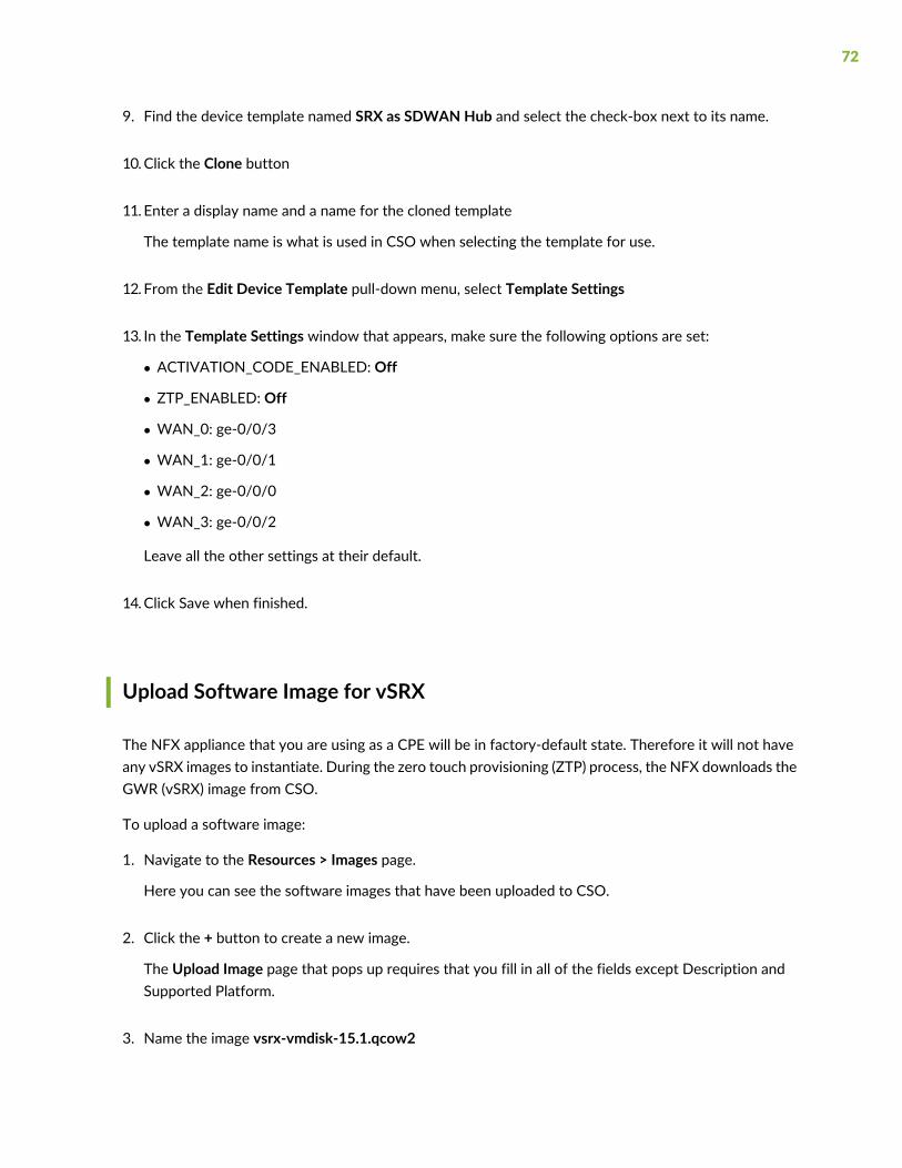
9. Find the device template named SRX as SDWAN Hub and select the check-box next to its name.
10.Click the Clone button
11. Enter a display name and a name for the cloned template
The template name is what is used in CSO when selecting the template for use.
12. From the Edit Device Template pull-down menu, select Template Settings
13. In the Template Settings window that appears, make sure the following options are set:
• ACTIVATION_CODE_ENABLED: Off
• ZTP_ENABLED: Off
• WAN_0: ge-0/0/3
• WAN_1: ge-0/0/1
• WAN_2: ge-0/0/0
• WAN_3: ge-0/0/2
Leave all the other settings at their default.
14.Click Save when finished.
Upload Software Image for vSRX
The NFX appliance that you are using as a CPE will be in factory-default state. Therefore it will not haveany vSRX images to instantiate. During the zero touch provisioning (ZTP) process, the NFX downloads theGWR (vSRX) image from CSO.
To upload a software image:
1. Navigate to the Resources > Images page.
Here you can see the software images that have been uploaded to CSO.
2. Click the + button to create a new image.
The Upload Image page that pops up requires that you fill in all of the fields except Description andSupported Platform.
3. Name the image vsrx-vmdisk-15.1.qcow2
72

4. Select VNF Image as the image type.
5. Click Browse and select the .qcow2 software image that you downloaded previously.
6. Select Juniper as the Vendor.
7. Select juniper-vsrx as the Family.
8. Fill in the Major Version Number, Minor Version Number, and Build Number as 15, 1, and X49-D161,respectively.
9. Click Upload. CSO displays a progress window as the file is uploaded.
Choose a Point of Presence (POP) for the Hub Site
A POP is a location within the service provider’s cloud in which PE routers and IPSec Concentrators arelocated. It is a regionally located access point through which customer sites gain access to hub devicesthat are placed within. The hubs are either data hubs, OAM hubs, or both. SPs often place POPs in theirnetwork so that they are geographically close to customer sites.
NOTE: The SP Administrator is the only onewith the privileges to create POPs. In a cloud-hostedCSO deployment, the SP Administrator links your tenant with an appropriate POP.
1. Navigate to the Resources > POPs page.
Here you can see a list of POPs available to you.
2. Make note of the POP name(s) and location(s) so that you can choose the appropriate one whenonboarding CPE devices.
73

Note Your Provider Hub Device
A provider hub device resides in a regional POP within the service provider’s network or cloud. Providerhub devices can be shared amongst multiple tenants through the use of virtual routing and forwarding(VRF) instances configured on the hub itself.
1. Navigate to the Resources > Cloud Hub Devices page.
Here you can see a list of all cloud hub devices, their POP, and site associations, status, model, serialnumber, and OS version.
2. Make note of the names of the Provider Hub devices available to you.
Create and Configure the Tenant’s Hub Site
In this section, we continue in the Customer Portal for your new tenant to create a provider hub site thatwill connect with the spoke site that we created in the previous section.
A provider hub site is the site on the SP’s network at which the provider hub device resides. The providerhub site is associated with a POP.
Ensure that you are on theResources > SiteManagement page in the Customer Portal of your new tenant.
1. From the Add pull-down menu on the Sites page, select Provider Hub Site
A new window, titled Add Provider Hub for <tenant-name>, appears.
2. Fill in the information requested in this window as follows:
• In the Configuration section, select the POP and Hub Device Name
The POP must exist and the hub device must be activated for it to show up in the list. The POP andHub device are provided by the SP Administrator. In the case of cloud-hosted CSO, this is JuniperNetworks.
3. Click OK when finished
74

Create and Configure a Spoke Site for the Tenant
In this section, we continue in the Customer Portal for the newly configured tenant in order to create anOn-Premise Spoke site.
This procedure begins in the Tenants window of the Administration Portal at the list of tenants.
1. Click on the name of the tenant that you just created
This will take you to the Customer Portal for that tenant. The Dashboard is displayed
2. Select Resources > Site Management link from the left-nav bar
3. In the Site Management window that appears, click the Add On-premise Spoke Site
A new window titled Add On-Premise Spoke Site for Tenant appears.
4. Fill out the information in the Site Information section.
5. In the Site Capabilities section, select the type of WAN and LAN capabilities you want for this site.
The available site capabilities are based on the tenant capabilities defined during tenant creation. Youcan choose one WAN capability in addition to one optional LAN capability.
For this example, choose only SD-WAN.
6. In the Configuration section, choose the appropriate Provider Hub from the pull-down menu.
7. Click Next
This brings up theWAN section.
8. Next to Device Series, select NFX 250 from the pull-down menu.
A horizontal list of device template boxes applicable to the NFX250 series devices appears.
9. Click the left (<) or right (>) arrow until you see the NFX250 as SD-WAN CPE box. Click on that box.
10. In the Device Information section:
• Fill in the Serial Number for the NFX250 device
• Leave Auto Activate selected
• For the Boot Image, select the NFX series software image that you previously uploaded to CSO.
The Boot Image tells CSO whether to update the device with a software image from the imagemanagement system or to use the image that exists on the device.
75

11. In theWAN Links section, select the Enable button next toWan_0
Fill in the following
• Link Type:MPLS
• Access Type: Ethernet
• Egress Bandwidth: 1000Mbps
• Click the > button next to Advanced Settings and fill in the following information:
• Provider:MPLS-Service-Provider
This can be any provider name, but it is a required field.
• Cost/Month: 1000
Use a realistic value for this cost per month. This number is used in SD-WAN link-switch calculations.
• Local Breakout: Off
For this example, leave the other settings at their default.
12. Select the Enable button next toWan_1
Fill in the following
• Type: Internet
• Access Type: Ethernet
• Egress Bandwidth: 25Mbps
Use the appropriate bandwidth number for your network. 25 is simply an example.
• Click the > button next to Advanced Settings and fill in the following information:
• Provider: Internet-Service-ProviderA
This can be any provider name, but is a required field.
• Cost/Month: 100
Use a realistic value for this cost per month. This number is used in SD-WAN link-switch calculations.
• Local Breakout: Off
For this example, leave the other settings at their default.
13.Click Next when finished
The window advances to the LAN section.
14. (Optional) Click the Add LAN Segment button
A new window appears titled Add LAN Segment
76

Fill in the following information in this window:
• Name: LAN2
This can be any name that makes sense in your deployment.
• VLAN ID: <Leave blank>
Enter a VLAN ID if required at the remote site. For this example, leave VLAN ID blank.
• Department: <Leave as Default>
In CSO, spoke site departments equate to security zones on the GWR. In this example, the Defaultsecurity zone will be used later when we create security policies. Creating multiple departments forthe spoke site creates multiple security zones with the same names on the GWR.
If you have departments set up already and the proper department is not shown, you can create oneby clicking on the Create Department link.
• Gateway Address/Mask: 10.0.2.1/24
Specify a unique and valid IPv4 address with subnet mask. This address will be the default gatewayfor endpoints in this LAN segment
• DHCP: Off
The NFX250 can provide DHCP server services for the remote LAN. For this example, leave DHCPset to off.
• CPE Ports: Select LAN_2 (ge-0/0/2) by clicking the check-box next to it.
• Click the -> button to move LAN_2 (ge-0/0/2) from the available list to the selected list
15.Click Save when finished
The Add LAN Segment window closes
16.Click Next
The window advances to the Summary section.
17.Review the Summary section
18.Click OK when you’re finished reviewing
A device activation window pops up and displays the progress of your site deployment.
NOTE: In the event of an error or delay, you can open a read-only SSH session to thedevice from CSO. This will allow you to troubleshoot connection or other issues.
77

Install License on Device
To install a license on a device, you use the Administration Portal
1. Navigate to Administration > Licenses > Device Licenses.
In the pop-up window that appears,
2. Click the check box next to the license file that you uploaded in step 3.
3. Click the Push License button at the upper-right part of the list and select Push.
The Push License window appears.
4. Select the name of the tenant that you created previously from the Tenant pull-down menu.
Your sites and devices appear under Sites and Devices.
5. Select the check box next to your tenant site to push the license to the CPE device at that site.
Install Application Signature
This step allowsthe CPE device to obtain the signature database needed for application identification.
To install an application signature:
1. Navigate to Adminstration > Signature Database
From the signature download you completed previously, you can now see theActive Database sectionhas the number of the downloaded database listed.
2. Click the Install on Device link under the Actions column.
In the new window that appears, you can elect to push the signatures to any device listed.
3. Select the check box next to the NFX250 device
4. Click OK
78

Add Firewall and NAT Policies to the Topology
In this section, we use the Customer Portal for your new tenant and create an intent-based firewall policythat blocks icmp-ping traffic.
1. In the Customer Portal for your tenant, navigate to Configuration > Firewall > Firewall Policy.
This brings up the Firewall Policy page. Here you can see a list of policies. You will see theDefault_FW_Policy which has 1 intent associated with it.
2. (Optional) Click the Default_FW_Policy link.
The page changes to show the intents associated with this firewall policy. You can see that the policyallows any traffic originating from any address in the trust zone to any address in the untrust zone. Toget back to the list of firewall policies, navigate to Configuration > Firewall > Firewall Policy
3. Click the Check-box next to Default_FW_Policy
4. Click the Deploy button
This brings up a Deploy window. Here you can select to run the policy deployment now or scheduleit to run later.
5. Click Deploy
Deployment progress bars appear as CSO deploys the policy. When it finishes, the Total Intents countincreases from 0 to 1.
The policy can be implemented at any time for any device within this tenant that works with zone-basedfirewall policies.
Add SD-WAN SLA-Based Steering Profiles and Policy
In this section, we use the Customer Portal to select an Path-Based Steering Profile and apply it to theSD-WAN Policy to specify that Microsoft Outlook traffic should pass over theWAN_0 overlay link ratherthan the default link, WAN_1.
1. Navigate to Configuration > SD-WAN > Path-Based Steering Profiles
2. Click the + to create a new profile
This brings up a Add PathProfile window.
79

In the new window, fill in the following information
• Name: <Enter a name for the profile, such as: Internet-Path
• Traffic Type Profile: INTERNET
• Path Preference: Internet
Priority value 1 is the highest priority. Higher priority profiles (lower numbers) take precedence overlower priority ones during SD-WAN events.
3. Click OK
This causes the window to close. The new policy shows in the list.
4. Navigate to Configuration > SD-WAN > SD-WAN Policy
This brings up the SD-WAN policy page which includes a list of all SD-WAN policies.
5. Click the + at the upper right part of the list to create a new policy
This brings up a policy builder with the Source section activated.
The Source defaults to All Sites.
The Application section defaults to Any.
Leave the source field at its default.
6. Click the + Select Destination
7. Type YouTube at the text-insertion point
This brings up a list of available applications.
8. Select YouTube from the list.
9. Click + Select Profile
This brings up a list of available profiles.
10. Select Internet-Path from the Path-Based Profiles [SLA] section of the list.
11.Click Save
This closes the builder window and shows the list of SD-WAN Policies.
12.Click the Deploy button
80

This brings up a Deploy window. Here you can select to run the policy deployment now or scheduleit to run later.
13.Click Deploy
Deployment progress bars appear as CSO deploys the policy. When it finishes, the Total Intents countincreases from 0 to 1.
Release History Table
DescriptionRelease
Starting with CSO Release 5.0.2, you can define your own custom application signatures foruse in SD-WAN policy. For more information regarding this optional step see Contrail ServiceOrchestration Administration Portal User Guide.
5.0.2
81

4CHAPTER
Hybrid WAN Deployment (uCPE)
Hybrid WAN (Distributed) Deployment Overview | 85
Hybrid WAN (Distributed) Deployment Architecture | 86
Your First Hybrid WAN (Distributed) Deployment | 88


Hybrid WAN (Distributed) Deployment Overview
This walkthrough highlights the steps, or workflows, that you need to complete in order to deploy a HybridWAN solution. We use an NFX250 Series device as the CPE and an SRX Series device as the Hub whichis located in the SP cloud. We indicate where, in the CSO GUI, you need to go to complete each step. Thedocument also provides some explanation of the choices that you need to make at each step. It assumesthat this is the first deployment you are attempting.
In the distributed deployment, customers access network services from a CPE device located at thecustomer’s site. These sites are called on-premise sites in this documentation. In the deployment workflowsused in the CSOGUI, this deployment is known asHybridWAN. Figure 33 on page 85 illustrates a simplifieddistributed deployment.
Figure 33: Simplified Hybrid WAN Deployment
g200
399
VNF on JuniperNFX Series Device
VNF
VNF
Initial configuration of the CPE device at the site is automated through the use of zero touch provisioning(ZTP) that is orchestrated through CSO. CSO also monitors the CPE device and its services, and can pushsoftware and configuration updates to the devices remotely, reducing operating expenses.
This deployment model is useful in environments where service delivery from the service provider’s cloudis costly. In fact, CSO has been designed to require only modest bandwidth, needing as little as 30kbpsfor probe and OAM traffic over Hybrid WAN connections where there are only a few sessions active.When AppQoe is involved, the bandwidth requirement increases to somewhere between 105kbps and2Mbps, depending on the number of sessions.
During ZTP operations, if new device images are needed, they can be downloaded as part of the ZTPprocess, or pre-staged on the device. In those circumstances, the bandwidth requirement increases to amaximum of 5Mbps only when device image download is needed. This makes these solutions applicableeven in cases where connection bandwidth is limited or noisy.
The HybridWAN deployment uses a CPE device such as an NFX Series Network Services platform or SRXSeries Services Gateway at the customer site and thus supports private hosting of network services at asite. The Hybrid WAN deployment can be extended to offer software defined wide area networking(SD-WAN) capabilities.
85

NOTE: If an SRX Series device is used as the CPE device at the customer site, it can not hostVNFs. It can still offer all of the built-in services inherent in an SRX Series device.
In the Hybrid WAN deployment model, there is typically only one path from the on-premise site back toheadquarters or the service provider cloud. The following sections describe the high-level architecture ofa Hybrid WAN deployment and provide a walkthrough of how to set up CSO for Hybrid WAN.
Hybrid WAN (Distributed) Deployment Architecture
In the Hybrid WAN deployment the Contrail Services Orchestration (CSO) software resides in the serviceprovider’s cloud, and is operated by the service provider in order to provide network services, hosted onCPE devices, at customer sites.
Figure 34 on page 86 shows a simple diagram of the Hybrid WAN solution. The cloud represents theservice provider network to which the customer site is connected.
Figure 34: Hybrid WAN Solutiong2
0039
9
VNF on JuniperNFX Series Device
VNF
VNF
As mentioned previously, the Hybrid WAN deployment makes use of on-premise CPE devices in order tolocalize the delivery of network services and provide gateway router (GWR) functionality. In this case, theJuniper Networks NFX Series or SRX Series devices act as the CPE devices.
In the case of NFX as CPE, the GWR function is provided by a built-in vSRX VNF and network servicesare hosted and provided from within the NFX that is located at the customer site. This makes the networkservices extremely responsive from the point of view of the customer LAN, while negating the need forcustomer traffic to traverse the WAN in order to access the services.
In the case of an SRX Series device as the managed CPE device, only services native to the SRX– firewall,NAT, and UTM, can be provisioned and managed at the customer site by CSO. Other services, such as
86

WAN optimization must be provisioned and managed separately from the SRX and cannot be managedby CSO.
In addition to the CPE devices, the Hybrid WAN solution also makes use of a provider edge (PE) router inthe service provider cloud. The PE router terminates IPSec tunnels and provides policy-based access tothe service provider’s MPLS network. The PE and CPE devices communicate over one or moreWAN linksand make use of MPLS/GRE or IPSec tunnels for secure transport. Supported device types for a HybridWAN deployment are shown in while the device roles and required software versions are shown inTable 9 on page 87.
Table 9: Hardware and Software Matrix for CPE Devices in a Hybrid WAN Deployment
Junos OS SoftwareRelease VersionModels SupportedPlatformRole
JunosOSRelease 16.1R3.00• MX960, MX480, or MX240 router witha Multiservices MPC line card
• MX80 or MX104 router with MultiservicesMIC line card
• OtherMX Series routers with aMultiservicesMPC or Multiservices MIC line card
See MPCs Supported by MX Series Routersand MICs Supported by MX Series Routersfor information aboutMX Series routers thatsupport Multiservices MPC and MIC linecards.
MX Series 3DUniversal EdgeRouter
PE Router andIPsecConcentrator(Hybrid WANdeploymentonly)
For NFX250: Junos OSRelease 15.1X53-D496
For NFX150: Junos OSRelease 18.3X85-D11
For SRX Series: Junos OSRelease 15.1X49-D172
For vSRX: Junos OS Release15.1X49-D172
• NFX250-LS1 device
• NFX250-S1 device
• NFX250-S2 device
• NFX150-S1 device
• NFX150-S1E device
• NFX150-C-S1 device
• NFX150-C-S1-AE/AA device
• NFX150-C-S1E-AE/AA device
• SRX300
• SRX320
• SRX340
• SRX345
• SRX4100
• SRX4200
• vSRX
• NFX SeriesNetworkServicesPlatforms
• SRX Seriesdevices
• vSRX on an x86server
CPE device
87

Selection of services, and some service management capabilities can be allocated to the customer by theservice provider using the CSOAdministration Portal. The customerwould then access the allowed servicesand management capabilities by using the Customer Portal.
CSOmanages the lifecycle of the VNFs hosted on theNFXCPE devices from creation in NetworkDesigner,through instantiation, deployment, and finally through replacement or retirement.
NOTE: Designer tools such as Network Designer are only available for on-premise deploymentsof CSO.
Your First Hybrid WAN (Distributed) Deployment
IN THIS SECTION
Modify Device Templates | 88
Add and Configure a New Tenant | 89
Add and Configure a Site for the Tenant | 90
Modify Device Templates
From this point on in this deployment example, we assume that you are logged in to CSO as an OpCoadministrator. The user name part of your credentials is an e-mail address that was used when your CSOaccount was set up. When an account is initially setup, CSO sends an e-mail to that address with a linkthat includes a one-time activation code. Clicking the link takes you to the CSO login page which thenprompts you to set a password.
In this section, we modify an existing device template so that it works for this example.
1. Enter the login credentials for the Administration Portal.
2. Navigate to Resources > Device Templates
3. Find the device template named NFX250 as Managed Internet CPE.
88

4. Select the check-box next to the template and then select Template Settings from the Edit DeviceTemplate pull-down menu.
A new window titled Template Settings appears
5. In the Template Settings window, ensure that the following things are set:
• ACTIVATION_CODE_ENABLED: ON
By requiring an activation code, a CPE device will not be allowed to communicate with CSO until thetenant has activated a site using the activation code. The value of the activation code will be set laterin the process.
• AUTO_DEPLOY_STAGE2_CONFIG: OFF
Stage 2 configurations are configurations that can be added to a device after the initial, stage 1,provisioning of the device. This setting prevents the automatic deployment of a stage 2 configuration.
• OOB_MGMT_ENABLED: OFF
This setting ensures that the jmgmt0 interface is not enabled on the NFX device. Since this is amanaged Internet service and the NFX device will be sitting on the customer’s premise, this mightbe a useful setting to prevent unwanted login by the tenant.
• WAN_0ge-0/0/11
Do not change any other settings.
6. Select Save when finished.
Add and Configure a New Tenant
In this section we use the Administrator Portal to add a tenant to CSO.
1. Select Tenants from the left-nav panel
2. Click theAdd Tenant button
If there are no tenants created yet, ’Add Tenant’ will be a button. If there are tenants, click the “+” tocreate a new tenant.
3. In the Add Tenant window that appears:
• Enter a name for your tenant such as Tenant1
• Fill in the Admin User information
89

• Select the check-boxes next to bothRoles in the Available section and click the arrow link to movethem to the Selected section
• The password expiry defaults to 180 days
You can set any value from 1 to 365 days.
• Click Next
• In the Deployment Info window, select the Hybrid WAN icon
• Click Next
The window advances to the Tenant Properties section. For this example, browse the Tenantproperties but do not make any changes
• Click Next
The window advances to the Summary section. Review the summary.
• Click OK
A pop-up message appears that tells you that the Add Tenant job was started. After some time, yournew tenant appears in the list of tenants.
Add and Configure a Site for the Tenant
In this section, we move to the Customer Portal for the newly configured tenant in order to create a site.
This procedure begins in the Tenants window of the Administration Portal, at the list of tenants.
1. Click on the name of the tenant that you just created
This will take you to the Customer Portal for that tenant. The Dashboard is displayed
2. Select Resources > Site Management link from the left-nav bar
3. In the Sites window that appears, click the Add On-Premise Spoke (Manual)
A new window titled Add On-Premise Spoke Site for <Tenant> appears.
4. Fill out the information in the Site Information section.
Enter a site name that makes sense, like: site1
If you fill in the address information, CSOwill use it to display the site onmaps on some of themonitoringpages.
5. Click Next
90

This brings up theWAN section.
6. Under Device Template, select the NFX250 from the Device Series pull-down menu.
This displays the device templates for NFX250 Series devices.
7. Select NFX250 as Managed Internet CPE
8. Fill out the information In the Device Information section
9. Disable Auto Activate
This enables the Activation Code field.
NOTE: If you leave Auto Activate enabled, CSO will attempt to connect with the deviceas soon as the site configuration is complete.
10. Enter an activation code for the NFX250.
This code must be entered when the device is powered-on for the first time in its final location.
NOTE: You cannot modify any settings for theWAN_0 interface because there are strictrequirements for this device template that theWAN_0must be an Internet-facing interface.
11.Click Next when finished
The window advances to the Summary
12.Review the Summary section
13.Click OK when you’re finished reviewing
You will see pop-up messages appear for site-creation job start and site-creation job finished.
NOTE: In the event of an error or delay, you can open a read-only SSH session to thedevice from CSO. This will allow you to troubleshoot connection or other issues.
91

5CHAPTER
Standalone Next-Generation Firewall(NGFW) Deployment
Next-Generation Firewall (NGFW) Deployment | 95


Next-Generation Firewall (NGFW) Deployment
IN THIS SECTION
NGFW Deployment Overview | 95
NGFW Deployment Architecture | 96
NGFW Deployment | 96
NGFW Deployment Overview
The NGFW deployment focuses on providing remote network security through the use of SRX SeriesNGFW devices as CPE at the spoke site; unlike the SD-WAN and Hybrid WAN deployments which focuson secure site-to-site connectivity and remote VNF deployment. A high-level view of the spoke site withNGFW is shown in Figure 35 on page 95.
Figure 35: NGFW Spoke Site
g300
529
Site
Next Generation Firewall
WAN Port
DHCPServer
LANLAN LANLAN
CSO
An NGFW deployment is carried out in the Customer Portal of CSO as a site deployment. The tenantunder which the site is deployed must have the NGFW service available. This service is included in thetenant configuration by the tenant administrator during tenant onboarding. The remainder of this document
95

provides a brief discussion of the architecture, and the steps that you need to perform in order to completea NGFW deployment in CSO.
NGFW Deployment Architecture
The architecture used in this example is described below.
The architecture for a cloud-hosted, CSO-managed NGFW deployment is very similar to any stand alonefirewall deployment as shown in Figure 35 on page 95. There is only one WAN port needed forcommunication with CSO. This port must get its IP address and gateway information from an availableDHCP server. The gateway must provide a path to the Internet so that the NGFW can communicate withJuniper’s redirect server.
CSO provisions the device and adds logging functionality. Optionally, default FW and NAT policies can beadded during the initial provisioning process. After provisioning the site administrator can push additionalGE, NAT, UTM, or IPS policies to the device.
Devicemonitoring is supported via the CSOGUIwhere you can view application and security logging data.
The remaining ports on the NGFW can be used for LAN communication at the site. Additionally, an EXSeries access switch can be added after the NGFW deployment. This addition allows for further LANmanagement within the site, including the ability to add CSO-managedMistWiFi access points to the site.
NGFW Deployment
The procedure you follow to complete this task varies slightly depending on whether you are in the roleof a CSO tenant administrator or OpCo administrator. A note is used where needed to account for thesevariances.
This procedure makes the following assumptions:
• You have already established your login credentials for CSO
• The tenant for which you are creating the NGFW site is called Example_Company, and has already beencreated
• The Example_Company tenant was added with NGFWWAN services capabilities
• There is a working DHCP server available from which the WAN port of the NGFW device will obtain:
• IP address
• Address of a gateway router that can route traffic to the Internet
96

If any of these things are not true, see Accessing Administration Portal, Accessing Customer Portal, orCreating a Single Tenant as appropriate.
The steps to deploy an NGFW site are as follows:
1. Login to CSO using your login credentials.
NOTE: If you are an OpCo administrator, navigate to Tenants in the left-nav bar andselect Example_Company from the list of tenants on the tenants page. If you are thetenant administrator, you will be placed in the Customer Portal for Example_Company
2. In the Customer Portal for Example_Company, Navigate to Resources > Site Management
The Sites page appears.
3. Click the Add button and select Add On-Premise Spoke (Manual) from the list of options
The Add On-Premise Spoke Site for Example_Company page appears.
4. In the Site Information section, give the site a name such as NGFW-Site1
5. In the Site Capabilities section, click the Next Gen Firewall icon
Depending on the configuration of the Example_Company tenant, there may be other icons available.Only select Next Gen Firewall for this example.
6. Click the > icon next to Address and Contact Information to expand this section
None of the fields are required, but adding address information for the site allows CSO to place an iconin the correct location for the site on maps on the monitoring page and show how it is linked to CSO.Without an address, CSO will place an icon at a default site.
7. Click the > icon next to Advanced Configuration
The two required fields, Name Server IP List and NTP Server are both pre-populated for you. Makechanges as needed for your network to any of the fields.
8. Click Next
The wizard advances to theWAN page.
9. In the Device Information section, fill in the serial number of the SRX device you are onboarding.
97

10.The Auto Activate button is turned on by default. Turn it off if you want to disable auto-activation anduse an activation code instead.
Auto-activation, if left on, begins immediately after this add spoke site procedure is completed.
11. The Zero Touch Provisioning (ZTP) button is turned on by default. Turn it off if you want to pre-stagethe device.
ZTP, if left on, begins immediately after the activation procedure, if enabled.
12. Select the appropriate In-Band Management port from the pull-down list
NOTE: In-Band Management refers to management traffic that uses a connection thatalso carries non-management traffic. In this case, the in-band management port is theWAN port over which the device communicates with both CSO and the Internet.
13. Select a firewall policy from the pull-down list
CSO has a built-in firewall policy called Default_Fw_Policy that is provided for you. This policy is azone-based policy intent that allows all traffic from any address in the trust zone to reach any addressin the untrust zone.
14. Select a NAT policy from the pull-down list
CSO has a built-in NAT policy called Default_NAT_Policy that is provided for you. This policy is aSource-NAT policy that translates the source IP address of any traffic originating in the trust zone tothe IP address of the trust-zone interface. ¯¯˘
15.Click Next
The wizard advances to the Summary page.
16.Review the configuration on the Summary page as shown in Figure 36 on page 99
98

Figure 36: NGFW Add Site Summary
The summary lists in text everything could be set in the wizard’s GUI.
NOTE: At the bottom of the summary page a Save JSON link is shown that allows youto download a JSON file of this site configuration. This JSON configuration can bemodifiedfor other sites so that they can be quickly imported without using the wizard workflow.
17.Click OK when satisfied, or click Back as needed to make any changes
If you need to edit anything, you can click the Edit links within the summary to go directly to that pageof the wizard.
The Site Activation wizard appears when you click OK.
18. If you left auto-activate turned on, the activation procedure begins at this point with the Site Activationpage appearing
If you turned off ZTP, you must copy the set commands from the Pre-Stage Device section of the SiteActivation wizard. If you left ZTP on, it will begin as part of the site activation wizard.
19. The Site Activationwindow proceeds through Prestage Device toDetect Device to Bootstrap Deviceand, finally to Provision Device
99

Each stage will report success as it completes its operation. The window can be closed at any point. Whilethe activation process is running, the Site Status column in the site list reports Activating and provides alink to View the activation wizard’s progress. The Site Status changes to Provisioned once all the stepsare successfully completed.
100

6CHAPTER
LAN Deployment
SD-LAN with EX Switch | 103


SD-LAN with EX Switch
IN THIS SECTION
LAN Deployment Overview | 103
SD-LAN Deployment | 104
LAN Deployment Overview
The SD-LAN deployment focuses on spoke site LAN connectivity using specific EX Series switches andVirtual Chassis (VC). Once deployed, you can manage the connected spoke site LANs through the EXswitch or VC. You can alsomanagemany aspects of the EX switch or VC itself. Figure 35 on page 95 showsa high-level view of an SD-LAN spoke site. It is important to note the Internet Gateway Device depictedin the diagram. The LAN switch at a spoke site must be deployed behind a router or CPE that is capableof routing traffic to CSO.
Figure 37: SD-LAN Spoke Siteg3
0034
8
CSO
Switch LAN1
LAN2Site
Internet Gateway Device
103

In addition to the SD-LAN deployment shown above, you can deploy EX Series access switches behindexisting CPE devices that act as the routers to allow the switch to communicate with CSO. You can deployEX Series LAN switches and VCs behind SRX Series and NFX250 Series CPE devices. You cannot deployan EX Series LAN switch or VC behind an NFX150 Series CPE device.
An SD-LAN deployment is performed in the Customer Portal of CSO as an on-premise site deployment.The tenant under which the site is deployed must have the LAN service available. This service is includedin the tenant configuration by the tenant administrator during tenant onboarding. The remainder of thisdocument provides the steps that you need to perform in order to complete an SD-LAN deployment inCSO.
SD-LAN Deployment
The procedure you follow to complete this task varies slightly depending on whether you are in the roleof a CSO tenant administrator or OpCo administrator. A note is used where needed to account for thesevariances.
This procedure makes the following assumptions:
• You have already established your login credentials for CSO
• The tenant for which you are creating the LAN site is called ExampleCo, and has already been created
• The ExampleCo tenant was added with LAN service capabilities
• If you are deploying a Virtual Chassis (VC) as the LAN switching device, the VC must be up and runningprior to beginning this procedure. You must have the serial number of the master switch in the VC.
If any of these things are not true, see Accessing Administration Portal, Accessing Customer Portal, orCreating a Single Tenant as appropriate.
The steps to deploy an SD-LAN site are as follows:
1. Login to CSO using your login credentials.
NOTE: If you are an OpCo administrator, navigate to Tenants in the left-nav bar andselect ExampleCo from the list of tenants on the tenants page. If you are the tenantadministrator, you will be placed in the Customer Portal for ExampleCo
2. In the Customer Portal for ExampleCo, Navigate to Resources > Site Management
The Sites page appears.
104

3. Click the Add button and select Add On-Premise Spoke (Manual) from the list of options
The Add On-Premise Spoke Site for ExampleCo page appears.
4. In the Site Information section, give the site a name such as LAN-Site1
5. In the Site Capabilities section, click the LAN icon
Depending on the configuration of the ExampleCo tenant, there may be other icons available. Onlyselect LAN for this example.
6. Click the > icon next to Address and Contact Information to expand this section
None of the fields are required, but adding address information for the site allows CSO to place an iconfor the site on maps on the monitoring page and show how it is linked to CSO.
7. Click the > icon next to Advanced Configuration
The two required fields, Name Server IP List and NTP Server are both pre-populated for you. Makechanges as needed for your network to any of the fields.
8. Click Next
The wizard skips past theWAN page to the LAN page.
9. In the Device Profile section, fill in the Device Name.
10. Select the appropriate Device Type from the pull-down menu
11. (Optional) Select the appropriate Device Model from the pull-down menu
12. In the Switch Details section, enter the Serial Number of the switch in the field.
13. The Auto Activate button is turned on by default. Turn it off if you want to disable auto-activation anduse an activation code instead.
If you left Auto Activate turned on, Skip to step 16.
14. (Optional) If you turned off Auto Activate, enter an activation code in the field that appears.
The code can be any combination of letters and numbers.
Remember this code.
105
15.The Zero Touch Provisioning (ZTP) button is turned off by default. Turn it on if the switch is upgradedto a JunosOS image versionwith support for Phone-Home-Client. If ZTP is disabled, youmust manuallycopy and paste the Stage-1 configuration (by using CLI) on to the switch.
ZTP, if left on, begins immediately after the activation procedure.
16. (Optional) Enter LAN information for the branch/spoke site
This optional step allows you to define where the remote site LANs are connected to the EX switch.You can define as many LANs as needed by following the next 5 steps.
a. Click the +
The Add LAN Segment window appears.
b. Enter a name for the LAN segment, such as LAN1, in the field provided
c. (Optional) Enter a VLAN ID for the LAN segment.
If no VLAN ID is needed, you can safely remove the pre-populated value from the field.
d. Select the switch ports to which the LAN segment is connected by clicking the Check-box next tothe port name and then clicking the right-arrow (->) between the Available and Selected lists.
Alternatively, you can select the Check-box for the desired port and then click the right-arrow (->)directly to the right of the port name.
e. Click Save when finished
You can add as many LAN segments as you need by repeating this procedure.
17.Click Next
The wizard advances to the Summary page.
18.Review the configuration on the Summary page
19.Click OK when satisfied, or click Back as needed to make any changes
If you need to edit anything, you can click the Edit links within the summary to go directly to that pageof the wizard.
If you left auto-activate turned on, the activation procedure begins at this point. The Site Activationpage appears. Skip to step 20.
106

If you turned off auto-activate, then your site appears in the list with a status of Configured. Go tonext step.
(Optional) If you turned off auto-activate, and are now ready to activate the site:
a. Click the site name link
This takes you to the site page for this site with the Overview tab highlighted.
b. Click the Devices tab
c. Click the Check-box next to the device name
The Stage1 Config button becomes active.
d. Click the Stage1 Config button
A new window appears containing the stage 1 configuration for this device.
e. Click the Copy to Clipboard button
f. Click OK
The window closes.
g. Using a console or SSH connection, install the copied configuration on the EX switch and commitit
Assuming that the required network connectivity is in place from the EX switch, the switch connectsback to CSO using an outbound SSH connection. When this connection is completed, the devicewill be activated in CSO; its status changes from Expected to Provisioned.
20. The Site Activationwindow proceeds through Prestage Device toDetect Device to Bootstrap Deviceand, finally to Provision Device
Each stage will report success as it completes its operation. The window can be closed at any point. Whilethe activation process is running, the Site Status column in the site list reports Activating and provides alink to View the activation wizard’s progress. After that, the Site Status changes to Provisioned once allthe steps are successfully completed.
NOTE: In the event of an error or delay, you can open a read-only SSH session to the devicefrom CSO. This will allow you to troubleshoot connection or other issues.
107

Once deployed, you can monitor and manage the switch or VC through the Customer Portal’s Switch PortOperational View.
108

7CHAPTER
Appendix A - Network FunctionVirtualization in Contrail ServiceOrchestration
Network Function Virtualization in the Contrail Service OrchestrationDeployments | 111
Number of Sites and VNFs Supported in Contrail Service Orchestration | 113
VNFs Supported by the Contrail Service Orchestration Solutions | 114


NetworkFunctionVirtualization in theContrail ServiceOrchestration Deployments
Network Function Virtualization (NFV) is a concept in which network functions traditionally performedby dedicated hardware devices are performed by software that runs on virtual machines in various networklocations. The virtual machines run software that performs traditional functions like routing, firewall, ornetwork address translation (NAT). These functions are known as virtual network functions (VNFs). InFigure 38 on page 111 the upper part of the diagram shows conventional physical network devices chainedtogether to provide network services. The lower part of the diagram shows how the same service chaincan be created from a pool of VNFs available on an NFX Series device.
Figure 38: Network Function Virtualization
g300
316
Local LAN
(NFX Series)x86-based Device
VNF Pool
VNFs in Path
NAT Device vSRXWAN Opt Router Brand XFirewall
NAT Device vSRX Router
WAN /Internet
Local LAN
NAT Device WAN /Internet
SRX SeriesFirewall
MX SeriesRouter
Juniper’s CSO solutions comply with European Telecommunications Standards Institute (ETSI) standardsfor lifecycle management of network service instances.
The Contrail SD-WAN Solution uses the following components for the Network Functions Virtualization(NFV) environment:
• For the Hybrid WAN and SD-WAN deployments:
• Network Service Orchestrator, together with Network Service Controller, provides ETSI-compliantmanagement of the life cycle of network service instances.
• Network Service Controller provides service-chaining and the VIM.
111

• The CPE device provides the NFV infrastructure (NFVI).
Other CSO components connect to Network Service Orchestrator through its REST API:
• Administration Portal, which you use to set up and manage your virtual network and customers througha graphical user interface (GUI).
Administration Portal offers role-based access control for administrators and operators. Administratorscan make changes; however, operators can only view the portal.
• Customer Portal, a GUI that your customers use to manage sites, CPE devices, and network services fortheir organizations.
Customer Portal offers role-based access control for administrators and operators. Administrators canmake changes; however, operators can only view the portal.
• Designer Tools:
• Configuration Designer, which you use to create configuration templates for virtualized networkfunctions (VNFs). When you publish a configuration template, it is available for use in ResourceDesigner.
• Resource Designer, which you use to create VNF packages. A VNF package consists of a configurationtemplate and specifications for resources. You use configuration templates that you create withConfiguration Designer to design VNF packages. When you publish a VNF package, it is available foruse in Network Service Designer.
• Network Service Designer, which you use to create a network service package. The package offers aspecified performance and provides one or more specific network functions, such as a firewall or NAT,through one or more specific VNFs.
NOTE: Designer Tools are only available in on-premise CSO deployments.
CSO solutions extend the NFV model through the support of physical network elements (PNEs). A PNEis a networking device in the deployment that you can configure through CSO, but not use in a servicechain. Configuration of the PNE through CSO as opposed to other software, such as Contrail or Junos OS,simplifies provisioning of the physical device through automation. Combining provisioning and configurationfor PNEs and VNFs provides end-to-end automation in network configuration workflows. An example ofa PNE is a vSRX device serving as a provider hub for the termination of IPsec and GRE data tunnels.
OSS/BSS applications andCSO components with OSS/BSS capabilities send requests to Network ServiceOrchestrator through its northbound RESTAPI. Network ServiceOrchestrator then communicates throughits southboundAPI to the northboundAPI of the appropriate, directly connected, component. Subsequently,each component in the deployment communicates through its southbound API to the northbound API ofthe next component in the hierarchy. Components send responses in the reverse direction.
112

Number of Sites and VNFs Supported in ContrailService Orchestration
Cloud-hosted CSO 5.0 supports up to 6000 sites and 2 VNFs for a Hybrid WAN deployment and up to6000 sites for a Hub and Spoke SD-WAN deployment.
An on-premise CSO deployment supports three environment types: small, medium, and large. The smallenvironment does not include any high availability features for the CSO platform itself, while medium andlarge deployments do support HA for the CSO platform.Table 10 on page 113 shows the number of sitesand VNFs supported for each environment.
Table 10: Number of Sites and VNFs Supported
Number of SitesSupported for a Huband Spoke SD-WANDeployment
Number of Sites and VNFsSupported for a DistributedDeployment
Number of VNFs Supported fora Centralized Deployment
DeploymentType
Up to 500Up to 500, 2 VNFs per site10 VNFsSmall
Up to 3500Up to 3500, 2 VNFs per site100 VNFs, 20 VNFs per Contrailcompute node
Medium
Up to 6000Up to 6000, 2 VNFs per site500 VNFs, 20 VNFs per Contrailcompute node
Large
Each environment has different requirements for:
• The number and specification of node servers and servers. SeeMinimum Requirements for Servers andVMs
• The number and specification of virtual machines (VMs). Provisioning VMs onContrail ServiceOrchestrationNodes or Servers
NOTE: For a cloud-hosted CSO deployment all of the node server and VM details are handledby Juniper Networks. The links above point to CSO 4.1 on-premise installation information.
113

VNFs Supported by theContrail ServiceOrchestrationSolutions
Contrail Service Orchestration (CSO) supports Juniper Networks and third-party VNFs listed inTable 11 on page 114.
Table 11: VNFs Supported by Contrail Service Orchestration
Deployment Model SupportNetwork Functions SupportedVersionVNF Name
Hybrid WAN and SD-WANdeployments supportsNAT, firewall, andUTM.
• Network Address Translation(NAT)
• Demonstration version of DeepPacket Inspection (DPI)
• Firewall
• Unified threat management(UTM)
vSRX KVMAppliance15.1X49-D123
Juniper NetworksvSRX
Hybrid WAN and SD-WANdeployments–NFX250 and NFX150platforms.
Firewall5.6.3Fortinet
Hybrid WAN and SD-WANdeployments–NFX250 and NFX150platforms.
Firewall16.04Single-leggedUbuntu
An on-premise version of CSO is not shipped with any VNFs. Immediately after installation you have toupload any desired VNFs to the CSO platform using the Administration Portal.
You can use VNFs in service chains and configure some settings for them in Network Service Designer.You can then view those network service configuration settings in the Administration Portal. Customerscan also configure some settings for the VNFs in their network services through Customer Portal. VNFconfiguration settings that customers specify in the Customer Portal override VNF configuration settingsspecified in Network Service Designer, which is not available in a cloud-hosted CSO deployment.
NOTE: Currently, SD-WAN deployments support only layer 2 (L2) service chains while HybridWAN deployments can support L2 and L3 service chains.
In a cloud-hosted deployment, CSOonly contains those VNFs installed by Juniper Networks’ administrators.Requests for additional VNFs must be made through your account manager and Professional Services.
114

8CHAPTER
Appendix B - Manual Staging of NFX
Install Junos Software onto NFX from USB Port | 117


Install Junos Software onto NFX from USB Port
This section details how to install Junos OS software version 15.1X53-D496.0 onto an NFX250 from aUSB drive. Doing this sets the device to the factory default state. We also perform some confirmationsteps and obtain the device’s serial number. This procedure is for an NFX250 device.
Before You Begin
In order for this procedure to succeed, you must have the following
• Physical access to the USB port of the NFX device
• A USB drive of at least 4GB containing the Junos OS Software image, 15.1X53-D496.0, inserted intothe USB port of the NFX
• Access to the console port of the NFX device (This can be physical access or access over a terminalserver.)
• A DHCP server that is reachable from the ge-0/0/11 interface of the NFX250. This DHCP server mustbe able to provide IP address, name server, and default gateway to the NFX upon request.
The following procedures contain comments that are added to clarify the steps that are discussed.
1. Ensure that the USB drive containing the Junos OS software image is inserted in the USB port of theNFX device.
This allows you to boot the NFX from the USB drive.
2. Access the NFX console either directly or using a terminal server.
You do not need to login; just ensure that you are actively connected.
3. Power off the NFX device.
4. Power on the NFX device.
5. Immediately return to the session that you have open to the console port of the nfx1 device.
From the console of the nfx1 device, press the ESC key every second until the following messageappears: Esc is pressed. Go to boot options.
117

NOTE: If you do not see this message in the console and the NFX appears to be bootingnormally, you need to wait for the boot to complete and then go back to step 1.
6. A menu appears after a brief time. Use the down arrow key to select Boot Manager, then press Enter.
7. When the Boot Manager menu appears, press Enter to boot from the USB00 drive.
8. When the GNU GRUB menu appears, use the up or down arrow keys to select Install Juniper Linuxwith secure boot support and then press Enter.
At this point, the NFX will install the software contained on the USB drive. Installation takes some time.You can keep your console connection active to watch the installation process.
The NFX is made up of multiple components that load and boot in a specific order. See NFX 250Overviewfor details. The PFE of the NFXmay take a fewminutes to complete the boot and allow the jsxe0 interfaceto obtain its address from DHCP.
You can login to the console of the NFX as root and confirm that the jsxe0 interface has received itsaddress using the following procedure:
1. Press Enter to refresh the login prompt
2. At the jdm login prompt, type root and press Enter.
NOTE: There is no password assigned to the root user at this point. For the purposes ofthis deployment exercise, do not set a root password at this time.
3. At the root@jdm:~# prompt, type cli and press Enter.
4. Type show interfaces jsxe0 and press Enter.
The jsxe0 interface has a number of logical interfaces used internally by the NFX for different purposes.You are looking for the jsxe0.0 logical interface. Confirm that the DHCP server has provided an addressin the proper range before continuing.
root@jdm:~# show interfaces jsxe0
Logical interface jsxe0.1 (Index 4)
Flags: Up
118

Input packets : 0
Output packets: 252
Protocol inet, MTU: 1500
Logical interface jsxe0.2 (Index 5)
Flags: Up
Input packets : 3
Output packets: 274
Protocol inet, MTU: 1500
Logical interface jsxe0.0 (Index 3)
Flags: Up
Input packets : 7097
Output packets: 8722
Protocol inet, MTU: 1500
Destination: 172.26.133.0/24, Local: 172.26.133.106,
Broadcast: 172.26.133.255
At this point, you can confirm that the DNS name server and default gateway are working by issuing theping command to some host on the Internet.
root@jdm:~ # cli
root@jdm:~ > ping www.juniper.net count 1
PING e1824.dscb.akamaiedge.net (23.223.165.73) 56(84) bytes of data.
64 bytes from a23-223-165-73.deploy.static.akamaitechnologies.com (23.223.165.73):
icmp_seq=1 ttl=56 time=2.67 ms
--- e1824.dscb.akamaiedge.net ping statistics ---
1 packets transmitted, 1 received, 0% packet loss, time 0ms
rtt min/avg/max/mdev = 2.670/2.670/2.670/0.000 ms
The last part of this procedure is to login to the Junos Control Plane (jcp) in order to obtain the deviceserial number which will be used later in the SD-WAN deployment.
root@jdm:~ > ssh vjunos0
Last login: Tue Jan 22 06:28:51 2019
--- JUNOS 15.1X53-D40.3 Kernel 32-bit FLEX
JNPR-10.1-20160217.114153_fbsd-builder_stable_10
At least one package installed on this device has limited support.
Run 'file show /etc/notices/unsupported.txt' for details.
root@:~ #cli
root> show chassis hardware
119

Hardware inventory:
Item Version Part number Serial number Description
Chassis DXXXXXXXXXX3
Pseudo CB 0
Routing Engine 0 BUILTIN BUILTIN RE-NFX250-S2
FPC 0 REV 04 650-066113 DXXXXXXXXXX3
CPU BUILTIN BUILTIN FPC CPU
PIC 0 REV 04 BUILTIN BUILTIN 10x10/100/1000 Base-T-2x1G
SFP-
Power Supply 0
Fan Tray 0 fan-ctrl-0 0, Front to Back
Airflow - AFO
Fan Tray 1 fan-ctrl-0 1, Front to Back
Airflow - AFO
The device serial number is listed on the Chassis line of the output. In this example, it is partly obscuredfor security purposes. Make note of the serial number for later use.
RELATED DOCUMENTATION
Building Blocks Used for Contrail Service Orchestration Deployments | 20
Hybrid WAN (Distributed) Deployment Overview | 85
SD-WAN Deployment Overview | 45
120