contributed by tan wee kiong this is slides taken from cisco certified network associate lesson...
TRANSCRIPT
Contributed byTan Wee Kiong
This is slides taken from Cisco Certified Network Associate Lesson Slides.Please do not distribute this around.This is only meant for reference.Hope this helps some understand better.There are also some extra information for those interested to know more.

No matter how you send your messages, no matter which physical medium you use, bandwidth is limited. This is due both to the laws of physics and to current technological advances.

•internetworking devices •type of data being transferred •topology •number of users •user's computer •server computer •power and weather-induced outages •and many other reasons.
Throughput usually refers to actual, measured, bandwidth, at a specific time of day, using specific internet routes, while downloading a specific file.
Some of the factors that determine throughput and bandwidth include the following:
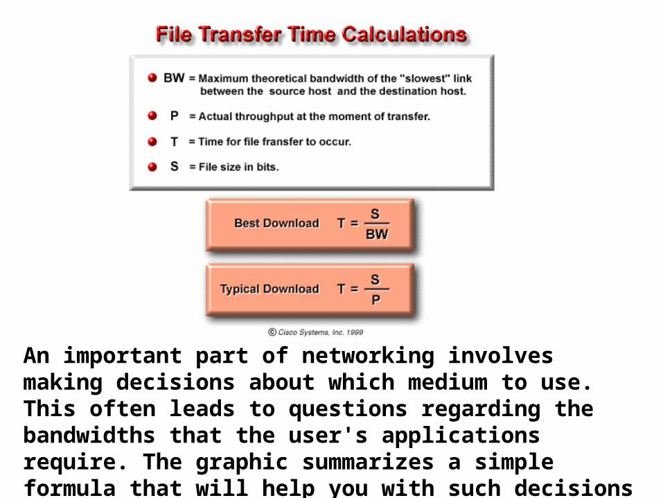
An important part of networking involves making decisions about which medium to use. This often leads to questions regarding the bandwidths that the user's applications require. The graphic summarizes a simple formula that will help you with such decisions

Protocol
• Protocol is a set of rules, or an agreement, that determines the format and transmission of data that make communication on a network more efficient.

7 layers of the OSI reference model
• Layer 7: Application
• Layer 6: Presentation
• Layer 5: Session
• Layer 4: Transport
• Layer 3: Network
• Layer 2: Data Link
• Layer 1: Physical
•All People Seem To Need Data Processing

The physical layer• Transmission of an unstructured bit stream
over a physical link between end systems.– Electrical, mechanical, procedural and functional
specifications– Physical data rate– Distances– Physical connector
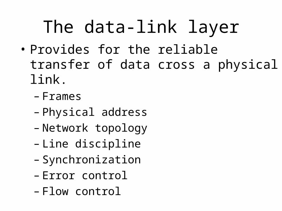
The data-link layer• Provides for the reliable transfer of data
cross a physical link.– Frames– Physical address– Network topology– Line discipline– Synchronization– Error control– Flow control

The network layer• Provides connectivity and path selection
between two host systems that may be located on geographically separated networks. – Packets– Virtual circuits– Route, routing table, routing protocol– Logical address– Fragmentation

The transport layer• Provides reliable, transparent transfer of
data over networks.– Segments, data stream, datagram– Connection oriented and connectionless– End-to-end flow control– Error detection and recovery– Segmentation & reassembly

The session layer• Establishes, manages, and terminates
sessions between two communicating hosts. – Sessions– Dialog– Conversations – Data exchange

The presentation layer• Ensures that the information that the
application layer of one system sends out is readable by the application layer of another system.– Format of data– Data structure– Data conversion– Data compression– Data encryption
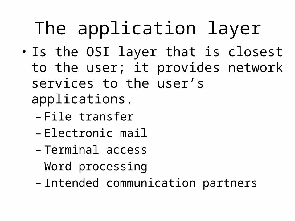
The application layer• Is the OSI layer that is closest to the user; it
provides network services to the user’s applications. – File transfer– Electronic mail– Terminal access– Word processing– Intended communication partners
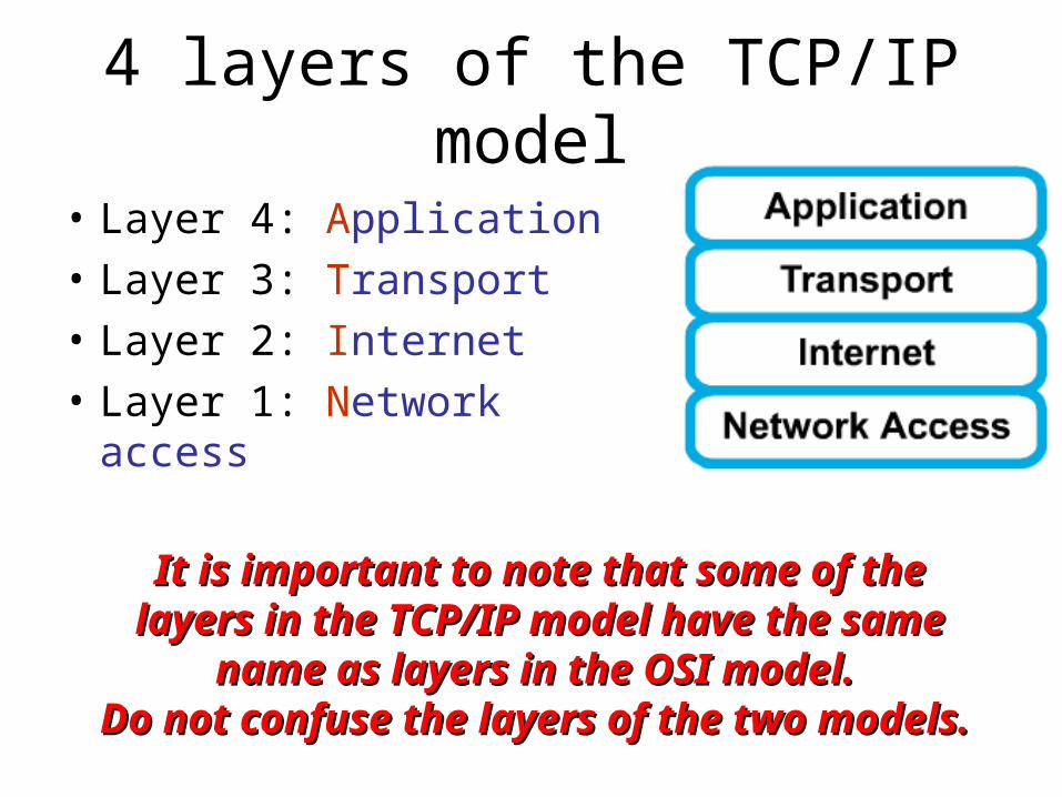
4 layers of the TCP/IP model
• Layer 4: Application
• Layer 3: Transport
• Layer 2: Internet
• Layer 1: Network access
It is important to note that some of the It is important to note that some of the layers in the TCP/IP model have the same layers in the TCP/IP model have the same
name as layers in the OSI model. name as layers in the OSI model. Do not confuse the layers of the two models. Do not confuse the layers of the two models.

The network access layer• Concerned with all of the issues that an IP
packet requires to actually make the physical link. All the details in the OSI physical and data link layers.– Electrical, mechanical, procedural and functional
specifications.– Data rate, Distances, Physical connector.– Frames, physical addressing.– Synchronization, flow control, error control.

The internet layer• Send source packets from any network on
the internetwork and have them arrive at the destination independent of the path and networks they took to get there. – Packets, Logical addressing.– Internet Protocol (IP).– Route , routing table, routing protocol.

The transport layer• The transport layer deals with the quality-
of-service issues of reliability, flow control, and error correction.– Segments, data stream, datagram.– Connection oriented and connectionless.– Transmission control protocol (TCP).– User datagram protocol (UDP).– End-to-end flow control.– Error detection and recovery.

The application layer• Handles high-level protocols, issues of
representation, encoding, and dialog control.
• The TCP/IP combines all application-related issues into one layer, and assures this data is properly packaged for the next layer. – FTP, HTTP, SMNP, DNS ...– Format of data, data structure, encode …– Dialog control, session management …

TCP/IP protocol stack

Comparing TCP/IP with OSI
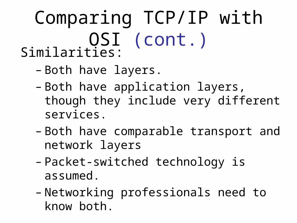
Comparing TCP/IP with OSI (cont.)
Similarities:– Both have layers.– Both have application layers, though they
include very different services.– Both have comparable transport and network
layers– Packet-switched technology is assumed.– Networking professionals need to know both.

Comparing TCP/IP with OSI (cont.)
Differences:– TCP/IP combines the presentation and session
layer issues into its application layer.– TCP/IP combines the OSI data link and
physical layers into one layer.– TCP/IP appears simpler because it has fewer
layers.– Typically networks aren't built on the OSI
protocol, even though the OSI model is used as a guide.
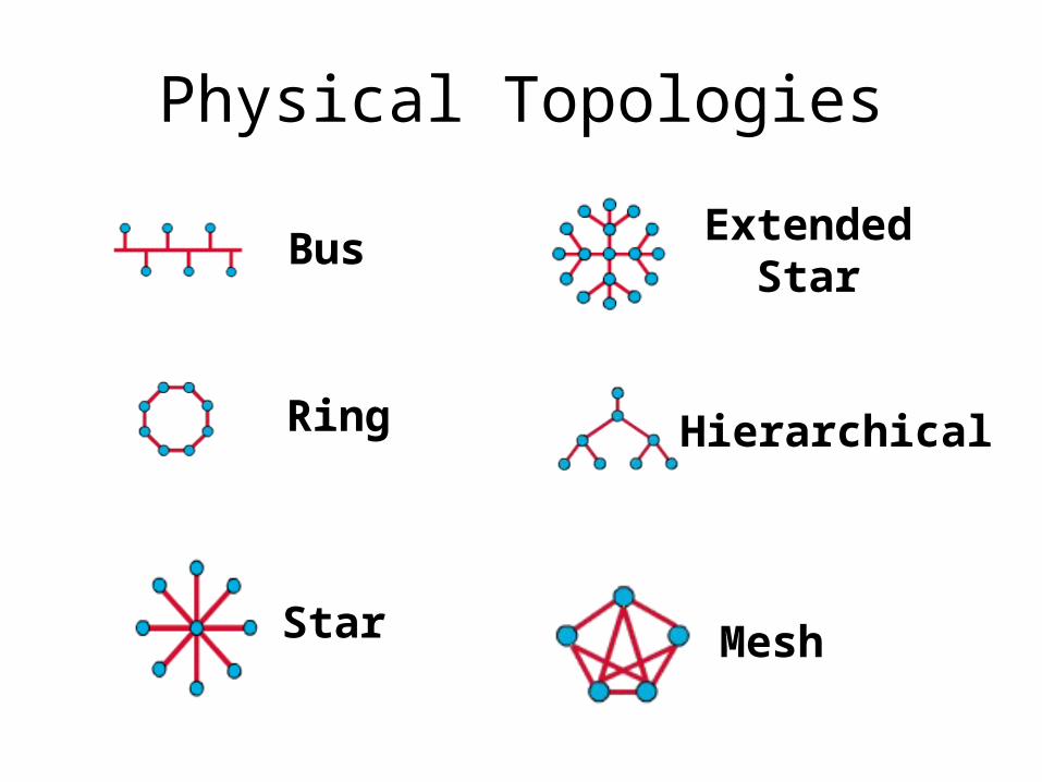
Physical Topologies
Bus
Ring
Star
ExtendedStar
Hierarchical
Mesh
Physical & Logical Topologies
• Physical topologies – Define the actual layout of the wire (media)
• Logical topologies – Define how the media is accessed by the
hosts

Physical Topologies
Bus
Ring
Star
ExtendedStar
Hierarchical
Mesh

Physical Topology: Bus
• Single backbone
• All hosts directly connected to backbone
• Each end of the bus must be properly terminated

Physical Topology: Ring
• No backbone
• A host is directly connected to each of its neighbors

Physical Topology: Star
• All devices connected to a central point
• Center of star is usually a hub or a switch

Physical Topology: Extended Star
• Connects individual star topologies together.
• At the center of the star is a hub or a switch.
• Extends the length and size of the network.

Physical Topology: Hierarchical
• Like the extended star except a computer controls traffic (not a hub or a switch).

Physical Topology: Mesh
• Each host has its own connection to every other host.
• Used in situations where communication must not be interrupted.

Technology: Token Ring
Token Ring
Token Passing
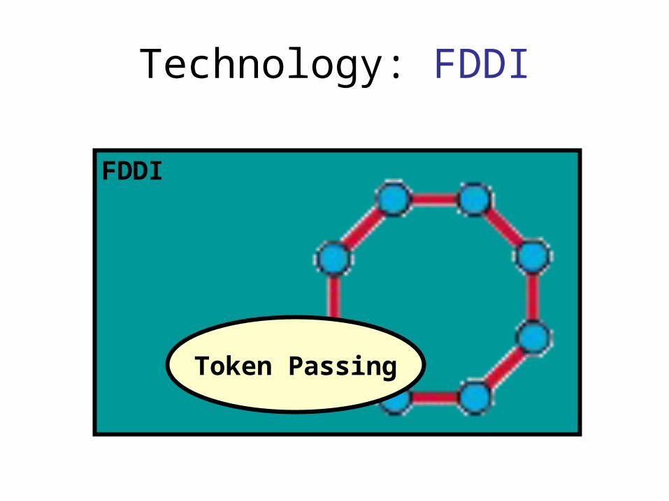
Technology: FDDI
FDDI
Token Passing

Technology: Ethernet
Ethernet
Broadcast
Noise (cont.)
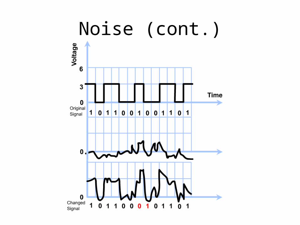
Noise (cont.)• Too much noise can corrupt a bit, thus
destroying the message.• Noise is unavoidable.• Kinds of noise:
– Thermal Noise.– Near end cross talk.– AC Power/Reference Ground Noise.– Electromagnetic Interference (EMI).– Radio Frequency Interference (RFI).

Signal modulation
• AM (amplitude modulation): the amplitude, or height, of a carrier sine wave is varied to carry the message.
• FM (frequency modulation): the frequency of the carrier wave is varied to carry the message.
• PM (phase modulation): the phase, or beginning and ending points of a given cycle, of the wave is varied to carry the message.

Binary encoding
• TTL: Transistor-Transistor logic
• NRZ-L: Non-Return to Zero-Level
• NRZI: Non-Return to Zero-Inverted
• NRZ-M: Non-Return to Zero-Mark
• Manchester Tx (Transmit)
• MLT3: Multi-Level Threshold-3
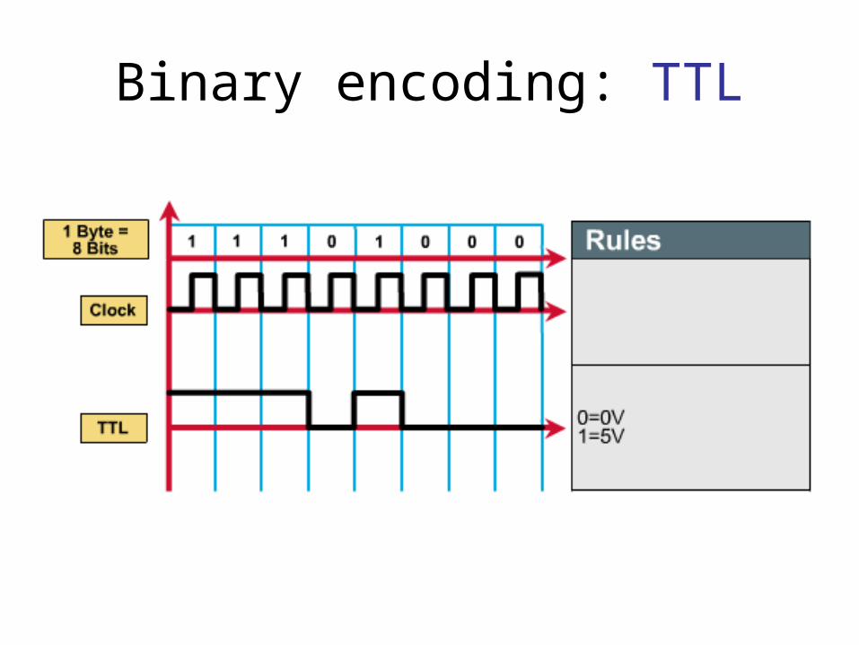
Binary encoding: TTL

Binary encoding: NRZ-L, I

Binary encoding: Manchester
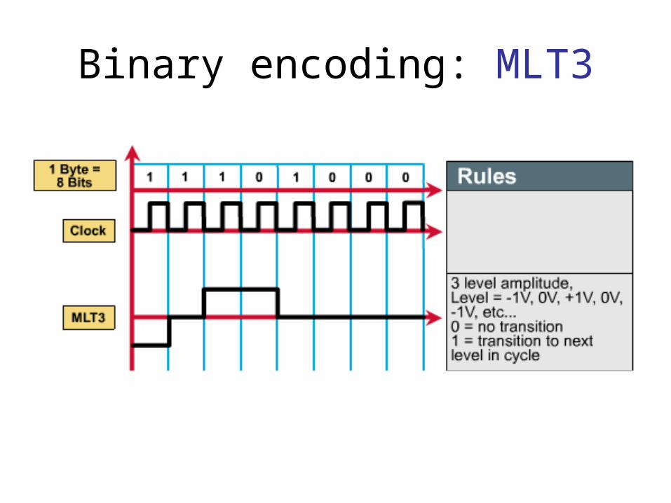
Binary encoding: MLT3

Binary encoding: Used
• Ethernet: – Manchester Tx+, Tx-
• Token-ring: – Differential Manchester
• Fast Ethernet: – MLT-3
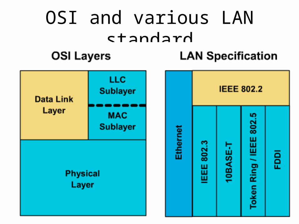
OSI and various LAN standard
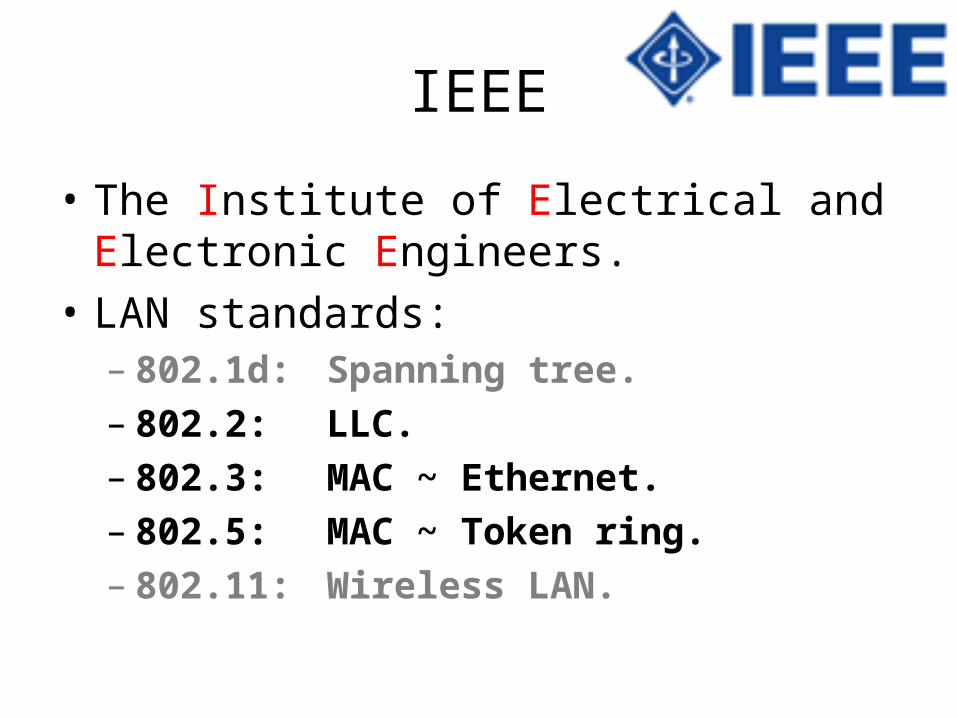
IEEE
• The Institute of Electrical and Electronic Engineers.
• LAN standards:– 802.1d: Spanning tree.– 802.2: LLC.– 802.3: MAC ~ Ethernet.– 802.5: MAC ~ Token ring.– 802.11: Wireless LAN.
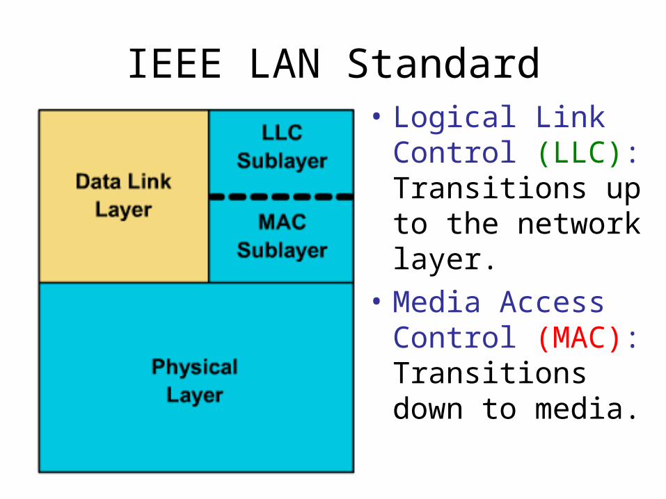
IEEE LAN Standard• Logical Link Control
(LLC): Transitions up to the network layer.
• Media Access Control (MAC): Transitions down to media.

Two Sub-layers WHY ?• LLC serves to communicate upward to
Network layer, independent of the specific LAN technology used and Upper layer.
• MAC serves to access and communicate downward to the technology-specific Physical layer.

MAC address format
The first six hexadecimal digits, which are administered
by the IEEE, identify the manufacturer or vendor.
The remaining six hexadecimal digits comprise the interface serial number.

Characteristics• Fiber Distributed Data Interface.• FDDI is popular as a campus backbone
technology.100 MbpsToken passingDual-ringFiber Optic CableTotal fiber length of 200KmStation distances up to 2Km

FDDI dual-ring (PR and SR)
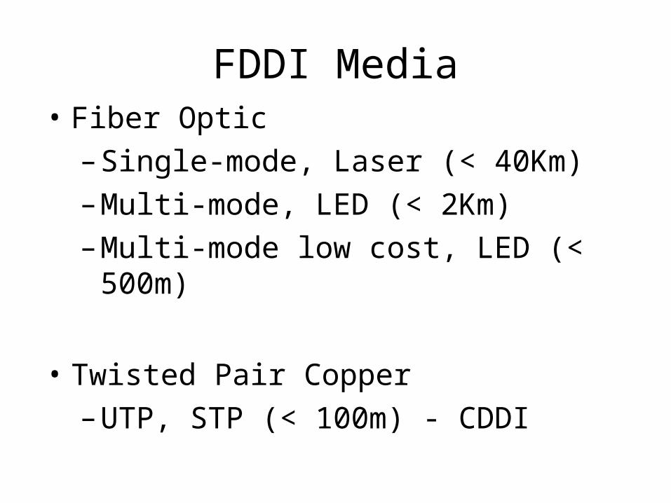
FDDI Media• Fiber Optic
– Single-mode, Laser (< 40Km)
– Multi-mode, LED (< 2Km)
– Multi-mode low cost, LED (< 500m)
• Twisted Pair Copper
– UTP, STP (< 100m) - CDDI

IP network address• Network layer addresses are 32 bits long.
• The are presented as four octets in dotted decimal format.
• The IP address has two components: Network ID and Host ID.
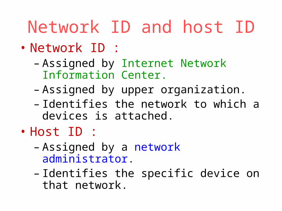
Network ID and host ID• Network ID :
– Assigned by Internet Network Information Center.
– Assigned by upper organization.– Identifies the network to which a devices is
attached.
• Host ID :– Assigned by a network administrator.– Identifies the specific device on that network.
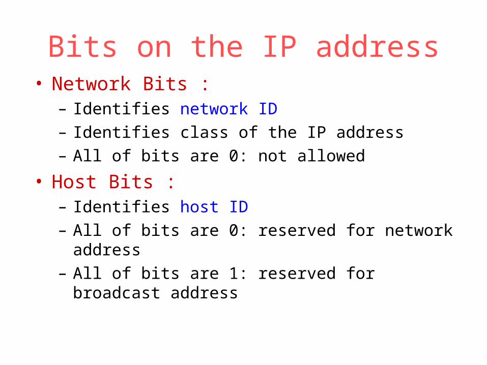
Bits on the IP address• Network Bits :
– Identifies network ID– Identifies class of the IP address– All of bits are 0: not allowed
• Host Bits :– Identifies host ID– All of bits are 0: reserved for network address– All of bits are 1: reserved for broadcast address
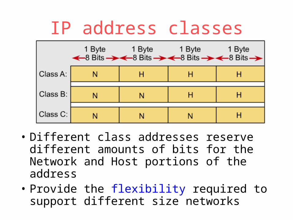
IP address classes
• Different class addresses reserve different amounts of bits for the Network and Host portions of the address
• Provide the flexibility required to support different size networks

IP address classes: Class A

IP address classes: Class A• The first bit of a Class A address is always 0.• The first 8 bits to identify the network part of the
address.• Possible network address from 1.0.0.0 to
127.0.0.0.• The remaining three octets can be used for the
host portion of the address.• Each class A network have up to 16,777,214
possible IP addresses.

IP address classes: Class B

IP address classes: Class B• The first 2 bits of a Class B address is always 10.• The first two octets to identify the network part of
the address.• Possible network address from 128.0.0.0 to
191.255.0.0.• The remaining two octets can be used for the
host portion of the address.• Class B network have up to 65,534 possible IP
addresses.

IP address classes: Class C
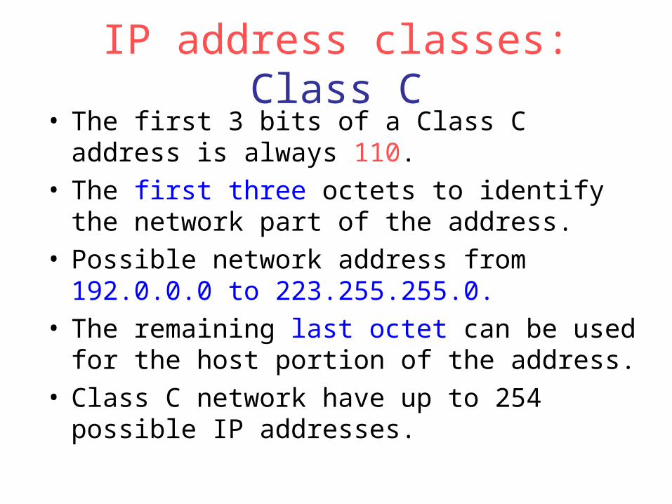
IP address classes: Class C• The first 3 bits of a Class C address is always
110.• The first three octets to identify the network part
of the address.• Possible network address from 192.0.0.0 to
223.255.255.0.• The remaining last octet can be used for the host
portion of the address.• Class C network have up to 254 possible IP
addresses.
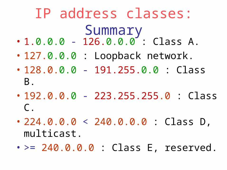
IP address classes: Summary• 1.0.0.0 - 126.0.0.0 : Class A.
• 127.0.0.0 : Loopback network.
• 128.0.0.0 - 191.255.0.0 : Class B.
• 192.0.0.0 - 223.255.255.0 : Class C.
• 224.0.0.0 < 240.0.0.0 : Class D, multicast.
• >= 240.0.0.0 : Class E, reserved.
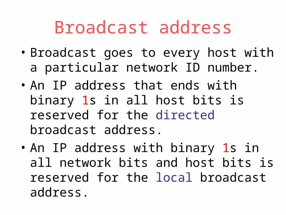
Broadcast address• Broadcast goes to every host with a
particular network ID number.
• An IP address that ends with binary 1s in all host bits is reserved for the directed broadcast address.
• An IP address with binary 1s in all network bits and host bits is reserved for the local broadcast address.
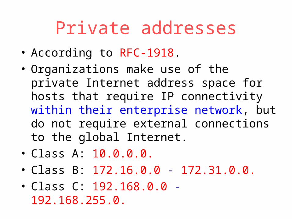
Private addresses• According to RFC-1918.• Organizations make use of the private Internet
address space for hosts that require IP connectivity within their enterprise network, but do not require external connections to the global Internet.
• Class A: 10.0.0.0.• Class B: 172.16.0.0 - 172.31.0.0.• Class C: 192.168.0.0 - 192.168.255.0.

Classification #2: IGP and EGP • Dynamic routes.• Interior Gateway Protocols (RIP, IGRP, EIGRP,
OSPF): – Be used within an autonomous system, a network of
routers under one administration, like a corporate network, a school district's network, or a government agency's network.
• Exterior Gateway Protocols (EGP, BGP):– Be used to route packets between autonomous systems.

IGPIGP
IGPIGP
IGP vs. EGP
EGPEGP

Classification #3: DVP and LSP• Distance-Vector Protocols (RIP, IGRP):
– View network topology from neighbor’s perspective.– Add distance vectors from router to router.– Frequent, periodic updates.– Pass copy of routing tables to neighbor routers.
• Link State Protocols (OSPF):– Gets common view of entire network topology.– Calculates the shortest path to other routers.– Event-triggered updates.– Passes link state routing updates to other routers.

RIP • Most popular.
• Interior Gateway Protocol.
• Distance Vector Protocol.
• Only metric is number of hops.
• Maximum number of hops is 15.
• Updates every 30 seconds.
• Doesn’t always select fastest path.
• Generates lots of network traffic.

IGRP and EIGRP • Cisco proprietary.• Interior Gateway Protocol.• Distance Vector Protocol.• Metric is compose of bandwidth, load,
delay and reliability.• Maximum number of hops is 255.• Updates every 90 seconds.• EIGRP is an advanced version of IGRP,
that is hybrid routing protocol.

OSPF • Open Shortest Path First.
• Interior Gateway Protocol.
• Link State Protocol.
• Metric is compose of cost, speed, traffic, reliability, and security.
• Event-triggered updates.
