contribution to solving an inherent problem when high ... · contribution to solving an inherent...
TRANSCRIPT

Journal of Materials Science and Engineering B 6 (5-6) (2016) 131-143 doi: 10.17265/2161-6221/2016.5-6.003
Contribution to Solving an Inherent Problem When High
Pressure Die-Casting Aluminium and its Alloys
Herbert Smetan
SMETAN Engineering GmbH, Siersburg, Germany
Abstract: The demands on ductility and fatigue strength of structural and chassis components are significantly higher than with other parts produced using cold-chamber-die-casting. Whereas, macroscopic oxide inclusions can be detected, classified as undesirable and removed from the production process by simple methods, the dispersed, ultrafine oxides which are more hidden are the so far underestimated source of extensive damage with regard to the ductility and fatigue strength of components produced in high-pressure-die-casting. Assuming that future applications of die-cast-components will increase demands even further, the author proposes an ultimate approach to solving these inherent problems by transferring experience from proven systems in the field of low-pressure-die-casting towards high-pressure-die-casting. In the currently dominating derivatives of the high-pressure die-casting method used for aluminium and its alloys, a great deal of effort is made to compensate for the symptoms of the more or less inherent disadvantages of very fast filling of the mould cavity. Basically, however, it must be assumed that most of the dispersed oxide-films are formed already at the stage of filling the aluminium into the shot-sleeve. This has led to a search for solutions in which the shot-sleeve is filled from below independent of evacuation of the mould cavity. As a result, various comparative studies have shown that components made by filling the mould cavity from below, combined with stronger evacuation of the cavity, produced the lowest amount of fine porosity in heat-treated parts. The author is convinced that the proposed concept of bottom-filling the slot sleeve under inert-gas-protection is ideally suited to producing high standard components of exceptional metallurgical quality. Combined with proven vacuum technology, die tempering and water-free spraying methods, it should ultimately be possible to achieve exceptionally high component properties.
Key words: Cast structural components, inherent limitations of HPDC, impact of oxide films on fatigue strength, creation of dispersed oxide films, concept for bottom-filling the slot sleeve.
1. Introduction
Independent of the ultimately successful solutions
towards future power train systems in private cars, the
manufacturers of construction elements made of
aluminium die-castings which may in future dominate
the field in light-weight bodywork and chassis parts –
still find themselves facing new challenges.
The demands on ductility and fatigue strength of
structural and chassis components are significantly
higher than with other parts produced using
cold-chamber die-casting. At the same time, inherent
die-casting problems are accepted both by the
traditional manufacturer and by the experienced user
Corresponding author: Herbert Smetan, Dipl. -Ing, research fields: material and foundry science and technology, manufacturing engineering.
of these components, full in the knowledge that the
potential available in the various aluminium foundry
alloys is not exploited in real components. Also, there
is a wide scatter in fracture strength, yield strength,
elongation and fatigue strength values i.e. values
which ultimately determine process capability are
locally very different and usually extremely low. Even
if the designer is able to compensate, by applying
additional safety margins in dimensioning, it is not
difficult for competitive materials and methods to
offset the potential weight advantage offered by
aluminium. In particular in the case of casting
methods, it should be questioned as to what ultimately
should be considered as the inherent limitations. The
author attempts here to do just that, both from the
practical stand point by examining the metallurgical
D DAVID PUBLISHING

Contribution to Solving an Inherent Problem When High Pressure Die-Casting Aluminium and its Alloys
132
aspects of aluminium foundry alloys and the material
requirements of a casting process.
2. Starting Point
Since 1971, the author has been engaged in various
positions and capacities as foundry and materials
specialist for suppliers of the global automotive
industry, including almost two decades leading an
international group of aluminium foundries which
specialise exclusively in the production of cylinder
heads and crankcases. In that period the basic question
was how it came about that, since the earliest days of
casting aluminium foundry alloys, it could be
accepted that the mechanical properties exhibited by
components remained significantly behind the actual
potential of these extremely capable but also
expensive materials, and that the values always
exhibited considerable scatter. Often, the more
demanding the alloy in question, the greater is the
discrepancy between the values obtained and those
that could be reached –for which reason hardly any
differences can be found in actual components. This
situation is reflected in the related standards and data
sheets. In contrast to ferrous casting materials, this
results in the users applying safety margins that
cannot be justified in any way for such a modern, light
weight construction material as aluminium and,
consequently, limits its wider use to a considerable
degree.
Essentially, the following points must be taken into
consideration:
In pure aluminium the shrinkage in volume
during solidification is 7% and in its alloys between
2.5 and 7%. On the other hand in ferrous alloys,
depending on the carbon content and graphite
formation, this amounts to only 0.6-3.2%.
In ferrous materials, because the density is three
times higher, the effective pressure at the interface
which promotes infiltration of residual melt into the
crystallising structure is significantly higher than that
of the aluminium foundry alloys.
The tendency to form more tenacious oxide skins
and oxide films, which often become dispersed
throughout the casting as folded bundles representing
detrimental interfaces in the structure. This is very
pronounced in aluminium foundry alloys and with few
exceptions other materials containing aluminium as an
additive - unique in industrial casting.
Another defect specific to aluminium is the
tendency for molten aluminium to take up hydrogen
and to precipitate this out during solidification mainly
in the form of finely dispersed spherical, gaseous
porosity at the grain boundaries and interfaces of the
eutectic phases.
The present day aluminium foundry alloys are
trusted to exhibit significant reserves in properties to
enable them to be used for an ever increasing range of
new products. This in turn places significantly
increased material-specific demands on these
components. Without question, successive,
step-by-step improvements both in the alloys
themselves and in the processing have enabled
improvements to be achieved, but these are
asymptotically approaching a process-specific limit.
Basically, because of their notch-like behaviour,
non-metallic discontinuities and material
heterogeneity have a very decisive influence on
properties under mechanical and thermal fatigue load
conditions. In that respect the dispersed oxide
impurities in the matrix of a component are extremely
detrimental. Any, even the briefest, interruption of the
oxide skin on molten aluminium during the complex
mould-filling process results in extremely thin oxide
films which become incorporated in the cast structure as
folded bundles and usually have an extremely negative
effect on the mechanical properties (Fig. 1) [1].
It is important to differentiate here, on the one hand,
between slowly growing oxide skins that form mainly
on the surface of aluminium melts in melting or
holding furnaces and can be incorporated in the
component as a result carelessness and, on the other
hand, oxide skins that form during the mould filling

Contribution to Solving an Inherent Problem When High Pressure Die-Casting Aluminium and its Alloys
133
(a)
(b) (c)
(d) (e)
Fig. 1 Principles of oxide formation on the surfaces of liquid aluminum alloys exposed to oxygen containing gases [1], (b) and (c) oxide formation during uncontrolled filling of the mould [1], (d) and (e) occlusion of oxide and air during uncontrolled filling of the mould [1].
process. The first type forms usually clusters of oxide
which are easy to recognise in the microstructure and
are usually conspicuous during crack detection. The
oxide formed during mould filling on the other hand
can become dispersed during that process and are not
detected using classical destructive or non-destructive
testing – also not even by means of sophisticated
metallographic methods of investigation. These
dispersed oxide films are hardly visible even to the
trained eye and can at best be detected using the

Contribution to Solving an Inherent Problem When High Pressure Die-Casting Aluminium and its Alloys
134
electron microscope.
Whereas, macroscopic oxide inclusions can be
detected, classified as undesirable and removed from
the production process, the dispersed, ultrafine oxides
which are more hidden are the source of extensive
damage. In the distant past, and repeatedly since then,
the author showed interest in the service life of cutting
tools employed for machining aluminium wheels
produced using low pressure die-casting and, as a rule,
excellent mould filling. Thereby, the cutting tool used
to machine wheels that had been cast from metal
melted in a medium frequency induction furnace
exhibited at most only a tenth of the service life of
those tools machining wheels from metal that had
been melted in a resistance heated crucible furnace.
The effect responsible for that was the same as with
the filling of the mould viz., the intensive movement
of the metal in the induction furnace breaks up the
oxide films on the surface of the melt and stirs in the
continuously, newly forming oxide films. As a result,
due to their very similar density, these oxide films
become dispersed throughout the molten metal and
cannot not be removed by the normal purification
processes used by die-casting foundries. This meant
that the trump card of aluminium viz., its ability to
provide protection against corrosion thanks to an
impermeable oxide layer, became its Achilles’ heel
when processed in the molten state.
Regardless of the nature of a discontinuity or
heterogeneity in the structure of an actual component,
their effect is defined basically by factors of shape,
length and size as well as inherent strength in relation
to the parent metal. In the case of alternating thermal
stresses, the difference in coefficients of thermal
expansion will also play a role.
Also the specific thermal conductivity of the
material will have an additional effect on the
resistance to thermal shock, because this causes a
change in the temperature gradient (this is mentioned
here only for sake of completeness). In this respect the
characteristic values for dynamic loading react much
more to discontinuities than do the values for
straightforward static loading. And, it is exactly these
dynamic loading values that are relevant for
construction design purposes. Basically, it should be
assumed that the strength of a material is usually
influenced more by its discontinuities than by the
characteristics of its matrix, for which reason it is not
helpful to introduce new alloys as long as we are far
from being able to exploit the potential of the existing
alloys. Even though attempts are made for various
applications to compensate for the inherent
disadvantages via high purity alloys, that should be
viewed simply for reasons of cost only as an
emergency solution.
In the past the author has always taken samples
from continuously casting ingots to illustrate the
potential of an aluminium foundry alloy with respect
to conventional values i.e. fracture strength, yield
strength, elongation and flexural fatigue strength, in
each case in comparison with the values used to
compare industrial casting methods. Admittedly this is
a demanding comparison and is stricter than the more
comparative measurement of a quality index normally
used to judge casting methods. Separately cast test
bars, still widely used for reference purposes, should
in the author`s opinion, be employed only to compare
the quality of a melt. These measurements have,
therefore, nothing to do with real components, the
properties of which are mostly influenced by process
effects.
Continuously cast ingots exhibit not only an
optimally solidified, uniform structure, but also the
ideal case with respect to inclusion of non-metallic
impurities. For that reason, when continuously casting
foil stock ingots, the oxide particles in the launder are
frequently measured in real time using the LIMCA
CM®-Method (Liquid Metal Cleanliness Analyzer)
by ABB [2], to achieve a melt free of dispersed oxides.
With similar goals in mind, the PoDFA®-Method
(Inclusion Identification and Quantification Analysis)
from ABB [2] is used in leading jobbing foundries for

Contribution to Solving an Inherent Problem When High Pressure Die-Casting Aluminium and its Alloys
135
quantitative assessment of oxide fines in melts. By
re-melting components, the so called Cold
PoDFA®-Method can also be used to judge the quality
of components by assessing the amount of fine,
dispersed oxide present. The fact that this method is
hardly ever used in foundries can be taken as an
indication of the low priority granted to the detection of
fine oxide inclusions in industrial practice.
Samples from actual components, produced using a
dynamic tilt casting method, were taken and used to
measure static strength values at room temperature
and fatigue strength values at 150 °C using various
aluminium foundry alloys in different heat treated
conditions (Table 1 and Fig. 2). Due to their
exemplary, low content of dispersed oxide films, the
values obtained significantly exceeded the values
regarded today as benchmarks for these alloys. The
principles involved here are described in detail by the
author elsewhere [3, 4] and in SMETAN engineering
Innovations Volume 1.
In die-casting, provided they are not dragged in
with the molten aluminium, these dispersed oxide
films are created during the actual mould filling,
especially during ladling. Even if the gating system
for gravity die-casting is designed according to the
parameters proposed by Friedrich Nielsen [5], oxide
films can be dispersed in particular by turbulence in
the pouring basin or at changes in direction at the
sprue – runner transition and thereafter. However, also
in the interior of the mould cavity, complex flow
patterns cause oxide films to be formed and stirred
into the molten metal [1]. In dynamic tilt casting,
freshly formed oxide films can be dispersed if the
molten metal is poured indiscriminately from a ladle
into the casting basin (Fig. 3).When this happens,
these oxide films become uniformly dispersed
throughout the component. This means that, if a melt
is already highly contaminated with fine, dispersed
oxide films in the casting basin, the significance of the
actual mould filling process is in fact less because, as
has been demonstrated in trials by the author, the
disadvantageous effect on the values of the material in
question increases exponentially already from an
extremely low concentration of such oxide particles.
Table 1 Strength values after various heat-treatments, obtained with actual components made from different aluminium casting alloys using dynamic tilt-casting.
Mechanical properties of various aluminium foundry alloys in various heat treatment conditions measured in real castings
At room temperature d0 = 5.0 mm Lt = 51.0 mm
AC-AlSi10MgCu AC-AlSi6Cu4 AC-AlSi7Cu3
RPO.2 Rm A5 RPO.2 Rm A5 RPO.2 Rm A5
MPa MPa % MPa MPa % MPa MPa %
As cast
Average 98 195 9.8 153 235 3.0 169 242 2.5
Conbustion chamber 101 192 8.4 163 239 2.8 178 249 2.5
Struts inbetween 92 197 12.0 143 239 3.3 161 243 2.8
Joint-face 101 197 9.0 153 226 3.0 168 233 2.2
T6W
Average 277 334 4.0 357 383 2.3 304 353 2.2
Conbustion chamber 272 326 4.4 347 384 2.2 299 351 1.0
Struts inbetween 280 345 4.0 393 393 2.7 312 366 2.6
Joint-face 278 331 3.5 332 371 2.1 302 343 2.1
T6A
Average 190 263 5.2 259 321 2.5 233 290 2.6
Conbustion chamber 194 264 5.0 263 327 2.7 233 300 2.4
Struts inbetween 189 266 6.0 266 322 2.4 239 293 2.4
Joint-face 187 259 4.5 248 314 2.3 227 276 2.9
T7A
Average 165 229 6.0 218 305 3.3 232 300 2.3
Conbustion chamber 168 229 5.5 222 312 3.5 234 306 2.5
Struts inbetween 166 233 6.5 224 311 3.2 241 307 2.1
Joint-face 161 225 6.0 209 293 3.3 220 286 2.2

Contribution to Solving an Inherent Problem When High Pressure Die-Casting Aluminium and its Alloys
136
Fig. 2 Fatigue strength values at elevated temperature obtained from actual cylinder heads in various aluminium casting alloys produced using a new tilt-casting method in comparison with conventional component values.
Fig. 3 Any interruption of the protective oxide skins on molten aluminium results in newly built, extremely thin oxide films.
If such grave differences, in particular in fatigue
strength and ductility, arise in gravity die-casting
components due to process-specific differences in
dispersed oxide films simply as a result of different
gating systems, all the more must be their effect in
pressure die-casting. In general the fatigue strength
and ductility values obtained by high pressure
die-casting lie significantly lower than those obtained
by gravity die-casting and take advantage, therefore,
to a much smaller degree of the potential in the
corresponding aluminium foundry alloys.
3. Specific Starting Points
In the currently dominating derivatives of the pressure
die-casting method used for aluminium and its alloys
(Fig. 4), a great deal of effort is made to compensate
for the symptoms of the more or less inherent
disadvantages of very fast filling of the mould cavity.

Contribution to Solving an Inherent Problem When High Pressure Die-Casting Aluminium and its Alloys
137
Fig. 4 Schematic representation of a die-casting unit with mould on a cold chamber die-casting machine for aluminium foundry alloys.
Table 2 Residual oxygen content in mould cavities as a function of different levels of vacuum, with and without flushing with nitrogen.
Residual oxygen content in mould cavities as a function of different levels of vacuum (with and without flushing with nitrogen)
Evacuation level of mould cavity 0% 10% 20% 30% 40% 50% 60% 70% 80% 90% 100%
O2 without N2-flushing 21% 19% 17% 15% 13% 11% 8% 6% 4% 2% 0%
O2 with N2-flushing 0% 0% 0% 0% 0% 0% 0% 0% 0% 0% 0%
In this connection customised standard electronic
real-time controls are employed to exercise a positive
influence on the millisecond filling of the mould cavity.
Also, using the simulation methods available today,
this filling process is optimised in such a way that
both the gating system and the systems forventingthe
cavity are designed and positioned in the best possible
manner.
Further, the mould cavity is very often connected to
a vacuum system and, depending on the air-tightness,
a larger or smaller negative pressure is formed before
the actual filling of the cavity. As the possible
negative pressure is, however, still far from a technical
vacuum, it can be assumed that the residual oxygen in
the cavity is sufficient to allow oxides to be formed
almost unhindered. Experience in vacuum metallurgy
supports this. The negative pressure created reduces
only the volume of gases trapped by the turbulent
filling process (Table 2).
Basically, however, it must be assumed that most of
the dispersed oxide films are formed already at the
stage of filling the aluminium into the shot sleeve
(Fig. 5). This filling is normally carried out using a
ladle or launder exposed to the open air and, in
traditional die-casting with the exception of the
accuracy of the quantity of metal fed to the shot
sleeve, is given little attention although it is an
essential step in the casting process. Further, it is
seldom that water and oil-based lubricant or
separating liquids are used sparingly at that stage, with
the result that – besides a dispersion of oxides – a
considerable amount of hydrogen is absorbed and
amorphous carbon is dispersed too (Fig. 6). For that
reason, the focus of the proposal made by the author
lies especially on this first process step.
4. Proposal for Avoiding Dispersed Oxide Films in Aluminium Pressure Die-Casting
In the past various proposals have been made to
reduce or eliminate this urgent problem by optimising
the feed of metal into the shot sleeve from above, or
by filling the shot sleeve from below. Whereas even

Contribution to Solving an Inherent Problem When High Pressure Die-Casting Aluminium and its Alloys
138
Fig. 5 Schematic representation of the filling of molten aluminium alloys into the shot sleeve of a cold chamber die-casting machine.
Fig. 6 Example for careless filling of the slot sleeve.
coverage with a protective gas during optimised,
low-turbulence feed of metal from above is able to
solve the problem of oxide formation only to a limited
degree, the filling from below by means of a feed tube
very often raises concerns from the point of machine
design. The author feels, however, that these
approaches could at least point to a method that is in
the interest of all die-casters producing ductile or
mechanically highly stressed components with a
certain amount of safety relevance. Various solutions
to filling the shot sleeve from below using a feed tube
can be found for conventional cold chamber die-casting
methods and for vertical squeeze casting machines in
the relevant technical literature. To date no other
solution of significant industrial consequence exists
except the company-specific Vacural-Process ®,
developed and patented by Müller Weingarten (now
Oskar Frech GmbH) and VAW Aluminium AG (now
Aleris) [6]. In the Vacural-Process ®, the evacuation of
the cavity and the shot sleeve is maintained throughout
the whole of the filling process.
As a result of this vacuum, the required amount of
metal is sucked via a feed tube out of the holding
furnace into the shot sleeve, and the air in the cavity as
well as the gases arising due to contact between the
melt and separating fluids with the cavity wall are
drawn off (Fig. 7). The amount of gases trapped in
castings made using this method is only a fraction of
that experienced with conventionally cast parts. Also
the smaller amount of pre-solidification in the shot
sleeve can be regarded as quality relevant.

Contribution to Solving an Inherent Problem When High Pressure Die-Casting Aluminium and its Alloys
139
Fig. 7 Principle of the Vacural-Process® [6].
On the one hand, however, filling from below via a
feed tube by evacuating the mould cavity and shot
sleeve depends very heavily on the air-tightness of the
parting lines between the die halves and between the
die and core sliders. On the other hand, it must be kept
in mind that, to be able to suck aluminium into the
shot sleeve a negative pressure of only 300 hPa is
sufficient. This is equivalent to an absolute pressure in
the mould cavity of around 700 hPa, which is still far
removed from a technical vacuum. As a result, the
mould cavity and the shot sleeve still contain
15Vol-%O2, which is sufficient to form dispersed
oxide films. Only a second evacuation step e.g. in the
course of further movement of the plunger, would
improve these conditions.
Likewise, however, components produced
experimentally via shot sleeve filling from below
using low pressure, have been shown to exhibit much
improved material properties. This has led to a search
for solutions in which the shot sleeve is filled from
below independent of evacuation of the mould cavity.
As a result, various comparative studies have shown
that components made by filling the mould cavity
from below, combined with stronger evacuation of the
cavity, produced the lowest amount of fine porosity in
the weld seam made using LASER welding. At the
same time components manufactured this way exhibit
much higher material properties, in particular
elongation values, than those achieved using
conventional high-pressure die-casting [7].
As before, it must be assumed that the amounts of
residual oxygen in the mould cavity and shot sleeve
are sufficient to cause oxidation of the surface of the
molten aluminium alloy which continually breaks up
during filling of the die cavity. Because of the
turbulence during high-pressure die-cast-specific
filling of the mould cavity, it must be assumed that the
melt takes up highly dispersed, filigree oxide films
and, de facto binds up the total amount of residual
oxygen in the cavity in the form of ultra-fine oxide
films that are then dispersed throughout the casting.
The Pore-Free Die-Casting-Process, patented already
in 1968, exploited exactly this situation by flooding
the mould cavity with gaseous oxygen and as a result,
creating a high vacuum chemically during the actual
filling of the mould [8].
From the perspective of experienced die-casting
experts, the problem of filling the shot sleeve from
below is that the shock waves resulting from actual
mould fillingshot are transmitted via the shot sleeve to
the feed tube, which makes it difficult to ensure
air-tightness in a process-reliable manner for a period
of time. Often, design-specific reasons are presented
to explain why this approach has not been able to
achieve industrialisation. As a rule, the improvements
in the various process steps of conventional mould

Contribution to Solving an Inherent Problem When High Pressure Die-Casting Aluminium and its Alloys
140
filling mentioned at the outset here have been able to
keep up with the steadily increasing demands of the
user, which is why the pressure for innovation in that
area has been bearable up to now.
Assuming that future applications of die-cast
components will increase demands even further, the
author proposes an ultimate approach to solving these
problems by transferring experience from proven
systems in the field of low-pressure die-casting to
high-pressure die-casting. In that connection, already in
the 70 s, the author developed a rapid change system
for process-capable coupling of low-pressure moulds to
low-pressure die-casting furnaces (Fig. 8a). In that
case the ceramic feed tube is attached outside the low
pressure die-casting furnace by means of a
compression seal fitting in a tool steel tube featuring a
spherical geometry at the contact face to the die. This
convex spherical surface at the die face is
accommodated by a concave spherical surface which
exhibits a slightly larger radius. As a result, this
connection is self-centering within a generous tolerance
range and provides a relatively robust seal, even when
there are axial deviations in angle, on a sealing face
that only requires a thin layer of graphite emulsion to
be applied regularly. This way it is possible, during
each cycle of the die-casting machine, to disconnect the
feed tube from the shot sleeve mechanically by way of
a short-stroke cylinder, which prevents the feed tube
from suffering the shock waves produced in the
system on casting. If the design details in the region of
the shot sleeve unit of a die-casting machine prevent
direct access with a telescopic feed tube, then this
problem could be solved by means of a shortened or
inclined feed tube. Also, modern insulation materials
offer the possibility of employing an intermediate
chamber, the net content of which is the amount of
metal required for one individual casting.
In this application the previous filling opening of
the shot sleeve can be fitted with a LASER
measurement system to measure the level of metal and
a LASER pyrometer to measure the temperature of the
metal, which enable further important parameters to
be used very precisely to control the process (Fig. 8b).
As the shot sleeve represents a hermetically sealed
system, gaseous nitrogen can be introduced into the
shot sleeve as a protective medium, which is then fed
into the mould during closing, thus expelling the air
from the whole of the mould cavity. Taking the
pressure-control which is employed as standard in
low-pressure die-casting, the level of the bath is
maintained just below the top of the feed tube between
each casting cycle. The feed tube is then docked onto
the shot sleeve by means of a short extension of the
telescope immediately prior to casting (Fig. 8c).
The surfaces at the interface between the feed tube
and the shot sleeve can be sprayed with a thin layer of
release agent or graphite emulsion.
Figs. 8d-8g show the sequence of mould filling
steps as part of the casting cycle. The docking of the
feed tube to the shot sleeve takes place at the same
time as the closing of the mould; the filling of the
shotsleeve starts from step 8d, whereby both the level
and temperature of the metal can be measured very
exactly as quality determining factors by means of
LASER devices, and also uses for control purposes.
As soon as the set level of metal is reached, the
plunger passes over the lower filling opening (Fig.
8e). As soon as this happens, the level of the metal in
the feed tube can be lowered, and subsequently the
feed tube itself as well, while the plunger advances
slowly. As soon as the feed tube has been uncoupled,
the ring-shaped sealing face can be sprayed with
release agent or graphite emulsion on both sides. This
is sufficient to keep these components functioning
properly within two maintenance cycles (Fig. 8f). The
actual shot takes place only at the moment after the
feed tube has been detached from the shot sleeve
(Fig. 8g). As the steps shown normally take place
parallel to the movement of the plunger, the entire
process takes place more or less in a time-independent
manner, as with conventional filling of the shot sleeve.
For maintenance and inspection purposes, the holding

Contribution to Solving an Inherent Problem When High Pressure Die-Casting Aluminium and its Alloys
141
(a) (b)
(c) (d)
(e) (f)
(g) (h)
Contribution to Solving an Inherent Problem When High Pressure Die-Casting Aluminium and its Alloys
142
Fig. 8 (a) Principle of a process- stable docking geometry for joining the feed tube to the shot sleeve of a die-casting machine, (b) between cycles, the shot sleeve is flooded with gaseous nitrogen and the melt maintained at the upper end of the feed tube, (c) at the cycle’s start the shot sleeve is continuously flushed with nitrogen and the feed tube docked onto the shot sleeve, (d) the melt is raised out of the feed tube, resulting in a protected low-turbulence filling of the shot sleeve, (e) when the plunger passes over the filling opening of the shot sleeve, the level of melt in the feed tube is lowered again, (f) when the plunger has passed the upper opening in the shot sleeve, the vacuum is activated in the mould, (g) the plunger is actuated according to a pre-set programme to implement the actual filling of the mould cavity and (h) for maintenance and inspection purposes the shot sleeve can be opened and the holding furnace withdrawn.
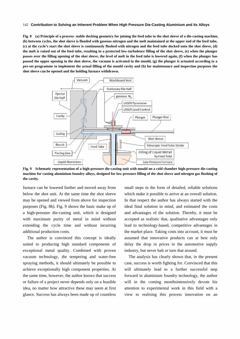
Fig. 9 Schematic representation of a high-pressure die-casting unit with mould on a cold chamber high-pressure die-casting machine for casting aluminium foundry alloys, designed for low pressure filling of the shot sleeve and nitrogen gas flushing of the cavity.
furnace can be lowered further and moved away from
below the shot unit. At the same time the shot sleeve
may be opened and viewed from above for inspection
purposes (Fig. 8h). Fig. 9 shows the basic make up of
a high-pressure die-casting unit, which is designed
with maximum purity of metal in mind without
extending the cycle time and without incurring
additional production costs.
The author is convinced this concept is ideally
suited to producing high standard components of
exceptional metal quality. Combined with proven
vacuum technology, die tempering and water-free
spraying methods, it should ultimately be possible to
achieve exceptionally high component properties. At
the same time, however, the author knows that success
or failure of a project never depends only on a feasible
idea, no matter how attractive these may seem at first
glance. Success has always been made up of countless
small steps in the form of detailed, reliable solutions
which make it possible to arrive at an overall solution.
In that respect the author has always started with the
ideal final solution in mind, and estimated the costs
and advantages of the solution. Thereby, it must be
accepted as realistic that, qualitative advantages only
lead to technology-based, competitive advantages in
the market place. Taking costs into account, it must be
assumed that innovative products can at best only
delay the drop in prices in the automotive supply
industry, but never halt or turn that around.
The analysis has clearly shown that, in the present
case, success is worth fighting for. Convinced that this
will ultimately lead to a further successful step
forward in aluminium foundry technology, the author
will in the coming monthsintensively devote his
attention to experimental work in this field with a
view to realising this process innovation on an
Contribution to Solving an Inherent Problem When High Pressure Die-Casting Aluminium and its Alloys
143
industrial scale.
References
[1] Campbell, J. 2013, Complete Casting Handbook, Elsevier.
[2] Brand Names of ABB Inc. Analytical Measurements, Quebec, Canada .
[3] Smetan, H. 2014. “Simply be Better is Enough- About the Simplicity of Casting.” Giesserei,01.
[4] Smetan, H., Rathner, T., Plank, K.H. 2014. “New, Innovative Casting Process for Production of High Performance Components Made of Aluminum Alloys and
its Application in Manufacturing.” Österreichische Giesserei Rundschau, 61.
[5] Nielsen, F. 1979. Gating and Feeding Principles. Giesserei-Verlag GmbH Düsseldorf.
[6] Cold-Chamber Vacural Technology by Oskar Frech GmbH + Co. KG Company Profile. Accessed July 2014. http://www.frech.com/produkte/kaltkammer/vacural-technologie.html.
[7] Kallien, L. 2008. University of Applied Sciences Aalen, Yearly Summary High Pressure Die Casting, Edition 45, Part 2: Technology, Giesserei 95, 05.
[8] Eck, S. E. and Radtke-Schrade, F. 1968. Pore-Free-Die-Casting, US-Patent No. 3,382,910.
Source of figures
Figs.1 and 3: Benno Leinen, Viscon Werbeagentur,
Eimersbergstraße 18, D-66787 Differten.
Fig. 2: John Campbell, Complete Casting Handbook 2013.
Fig. 7: Oskar Frech GmbH & Co KG, Lortzingstraße 56,
D-73614 Schorndorf.
All other figures: Herbert Smetan, SMETAN engineering
GmbH, Auf der Hardt 34, D-66780 Rehlingen-Siersburg.