contributions to meta-modeling tools and methods
TRANSCRIPT
Contributions to Meta-Modeling Tools and Methods
by
Adrian Pop
June 2005 ISBN 91-85299-41-3
Linköping Studies in Science and Technology Thesis No. 1162 ISSN 0280-7971
LiU-Tek-Lic-2005:17
ABSTRACT
Highly integrated domain-specific environments are essential for the efficient design of complex physical products. However, developing such design environments is today a resource-consuming error-prone process that is largely manual. Meta-modeling and meta-programming are the key to the efficient development of such environments.
The ultimate goal of our research is the development of a meta-modeling approach and its associated meta-programming methods for the synthesis of model-driven product design environments that support modeling and simulation. Such environments include model-editors, compilers, debuggers and simulators. This thesis presents several contributions towards this vision, in the context of the Modelica framework.
Thus, we have first designed a meta-model for the object-oriented declarative modeling language Modelica, which facilitates the development of tools for analysis, checking, querying, documentation, transformation and management of Modelica models. We have used XML Schema for the representation of the meta-model, namely, ModelicaXML. Next, we have focused on the automatic composition, refactoring and transformation of Modelica models. We have extended the invasive composition environment COMPOST to handle Modelica models described using ModelicaXML.
The Modelica language semantics has already been specified in the Relational Meta-Language (RML), which is an executable meta-programming system based on the Natural Semantics formalism. Using such a meta-programming approach to manipulate ModelicaXML, it is possible to automatically synthesize a Modelica compiler. However, such a task is difficult without the support for debugging. To address this issue we have developed a debugging framework for RML, based on abstract syntax tree instrumentation in the RML compiler and support of efficient tools for complex data structures and proof-trees visualization.
Our contributions have been implemented within OpenModelica, an open-source Modelica framework. The evaluations performed using several case studies show the efficiency of our meta-modeling tools and methods.
This work has been supported by the National Computer Science Graduate School (CUGS), the ProViking Graduate School, the SSF financed Research on Integrational Software Engineering (RISE) project and the Vinnova financed Semantic Web for Products (SWEBPROD) project. Also, we acknowledge the cooperation with Reasoning on the Web with Rules and Semantics (REWERSE) "Network of Excellence" (NoE) funded by the EU Commission and Switzerland within the "6th Framework Programme" (FP6), Information Society Technologies (IST).


Acknowledgements
...to Tzitzici, family, friends, supervisors, colleagues, and all the others: Thank You!
...to all the fish out there, beware!
Adrian Pop Linköping, June 3, 2005


i
Table of Contents
Chapter 1 Introduction.......................................................................................1 1.1 Background and Related Work................................................................2
1.1.1 Systems, Models, Meta-Models and Meta-Programs .........................2 1.1.2 Meta-Modeling and Meta-Programming Approaches ........................3 1.1.3 Component Models for Invasive Software Composition ....................5 1.1.4 The Modelica Language......................................................................8 1.1.5 Integrated Product Design and Development....................................10 1.1.6 Compiler Construction and Natural Semantics.................................11 1.1.7 Semantic Web and Description Logics .............................................14
1.2 Research topics ......................................................................................16 1.2.1 Design and Application of Meta-Modeling Methods .......................17 1.2.2 Methods and Tools for Debugging of Meta-Programs .....................17
1.3 Thesis Contributions..............................................................................18 1.4 Thesis Structure .....................................................................................19 1.5 Conclusions and Future Work ...............................................................24
1.5.1 Conclusions.......................................................................................24 1.5.2 Future work directions ......................................................................24
Chapter 2 ModelicaXML: A ModelicaXML Representation with Applications ..........................................................................................................27
2.1 Abstract..................................................................................................27 2.2 Introduction ...........................................................................................27 2.3 Related Work.........................................................................................29 2.4 Modelica XML Representation .............................................................29
2.4.1 The eXtensible Markup Language (XML)........................................30 2.4.2 ModelicaXML Example ...................................................................32 2.4.3 ModelicaXML Schema (DTD/XML-Schema) .................................34
2.5 ModelicaXML and XML tools..............................................................39 2.5.1 The Stylesheet Language for Transformation (XSLT) .....................39 2.5.2 The Query Language for XML (XQuery).........................................41 2.5.3 Document Object Model (DOM)......................................................42
2.6 Towards an Ontology for the Modelica Language ................................42 2.6.1 The Semantic Web Languages..........................................................43 2.6.2 The roadmap to a Modelica representation using Semantic Web Languages ......................................................................................................47
2.7 Conclusion and Future work..................................................................48 2.8 Acknowledgements ...............................................................................48

ii
Chapter 3 Composition of XML dialects: A ModelicaXML case study .......49 3.1 Abstract ..................................................................................................49 3.2 Introduction............................................................................................50 3.3 Background............................................................................................51
3.3.1 Modelica and ModelicaXML ............................................................51 3.3.2 Compost ............................................................................................53
3.4 COMPOST extension for Modelica.......................................................56 3.4.1 Overview ...........................................................................................56 3.4.2 Modelica Box Hierarchy ...................................................................57 3.4.3 Modelica Hook Hierarchy .................................................................58 3.4.4 Examples of composition and transformation programs ...................60
3.5 Conclusion and Future work ..................................................................63 3.6 Appendix................................................................................................63
Chapter 4 An Integrated Framework for Model-driven Product Design and Development Using Modelica ........................................................................65
4.1 Abstract ..................................................................................................65 4.2 Introduction and Related Work..............................................................65 4.3 Architecture overview............................................................................67 4.4 Detailed framework description.............................................................68
4.4.1 ModelicaXML...................................................................................68 4.4.2 Modelica Database (ModelicaDB) ....................................................69 4.4.3 FMDesign..........................................................................................70 4.4.4 The Selection and Configuration Tool ..............................................72 4.4.5 The Automatic Model Generator Tool ..............................................73
4.5 Conclusions and Future Work................................................................73 4.6 Acknowledgements................................................................................74 4.7 Appendix................................................................................................75
Chapter 5 The Modelica Standard Library as an Ontology for Modeling and Simulation of Physical Systems .....................................................................77
5.1 Abstract ..................................................................................................77 5.2 Introduction and Related Work..............................................................77 5.3 Modelica ................................................................................................78 5.4 Modelica Standard Library (MSL) ........................................................79
5.4.1 Overview of the ontology..................................................................79 5.4.2 Discussion on the Modelica Standard Library ..................................81 5.4.3 Example.............................................................................................82
5.5 Conclusions and Future Work................................................................84 5.6 Acknowledgements................................................................................84 5.7 Appendix................................................................................................84

iii
Chapter 6 Debugging Natural Semantics Specifications ...............................87 6.1 Abstract..................................................................................................87 6.2 Introduction ...........................................................................................88 6.3 Related Work.........................................................................................88 6.4 Natural Semantics and the Relational Meta-Language (RML) .............89
6.4.1 A short example of an RML specification ........................................90 6.4.2 The rml2c compiler and the runtime system.....................................92
6.5 Debugger Design and Implementation ..................................................93 6.5.1 Overview...........................................................................................94 6.5.2 Design Decisions ..............................................................................95 6.5.3 Instrumentation function ...................................................................96 6.5.4 Type reconstruction in the runtime system .......................................97 6.5.5 Debugger implementation.................................................................98
6.6 Debugger Functionality .........................................................................99 6.6.1 Starting the RML Debugging Subprocess....................................... 100 6.6.2 Setting/Deleting Breakpoints .......................................................... 100 6.6.3 Stepping and Running..................................................................... 101 6.6.4 Examining Data .............................................................................. 103 6.6.5 Additional commands ..................................................................... 105
6.7 The Data Value Browser ..................................................................... 106 6.8 The Post-Mortem Analysis Tool ......................................................... 108 6.9 Performance Evaluation ...................................................................... 109
6.9.1 Code growth.................................................................................... 109 6.9.2 The execution time.......................................................................... 110 6.9.3 Stack consumption .......................................................................... 110 6.9.4 Number of relation calls.................................................................. 111
6.10 Conclusions and Future Work ............................................................. 111 6.11 Acknowledgements ............................................................................. 111 6.12 Appendix ............................................................................................. 112
Chapter 7 Related research contributions .................................................... 113 7.1 Introduction ......................................................................................... 113 7.2 A Functionality Coverage Analysis of Industrially Used Ontology Languages ........................................................................................................ 113 7.3 Deriving a Component Model from a Language Specification: An Example Using Natural Semantics.................................................................... 114 7.4 A Portable Debugger for Algorithmic Modelica Code........................ 114 7.5 ModelicaDB – A Tool for Searching, Analyzing, Crossreferencing and Checking of Modelica Libraries ................................................................. 115 7.6 Towards Comprehensive Meta-Modeling and Meta-Programming Capabilities in Modelica.................................................................................... 115
Bibliography ........................................................................................................ 117

iv

v
Table of Figures
Figure 1-1. The Object Management Group (OMG) 4-Layered Model Driven Architecture (MDA)................................................................................4
Figure 1-2. Meta-Modeling and Meta-Programming dimensions. ............................5 Figure 1-3. Black-box vs. Gray-box (invasive) composition. Instead of
generating glue code, composers invasively change the components. ............................................................................................6
Figure 1-4. Invasive composition applied to hooks result in transformation of the underlying abstract syntax tree..........................................................7
Figure 1-5. MathModelica modeling and simulation environment. ..........................8 Figure 1-6. Integrated model-driven product design and development
framework. ............................................................................................10 Figure 1-7. The Semantic Web layered architecture................................................15 Figure 1-8. Thesis Structure.....................................................................................23 Figure 2-1. The program (root) element of the ModelicaXML Schema. ............. 35Figure 2-2. The definition element from the ModelicaXML Schema. ............ 36Figure 2-3. The component element from the ModelicaXML Schema. .............. 37Figure 2-4. The equation element from the ModelicaXML Schema.................. 37Figure 2-5. The algorithm element from the ModelicaXML Schema. .............. 38Figure 2-6. The expressions from ModelicaXML schema. .....................................39
...................................................................43Figure 2-7. The Semantic Web Layers. Figure 3-1. The layers of COMPOST......................................................................54 Figure 3-2. The XML composition. System Architecture Overview.......................57 Figure 3-3. The Modelica Box Hierarchy defines a set of templates for each
language structure. ................................................................................58 The Modelica Hook Hierarchy.Figure 3-4.
.......................................67
igure 5-1. Visual construction of models using MathModelica.............................81
.....83
.............................................................59 Figure 4-1. Design framework for product development. Figure 4-2. Modelica and the corresponding ModelicaXML representation........... 69Figure 4-3. FMDesign – a tool for conceptual design of products. .........................71 Figure 4-4. FMDesign information model...............................................................75 Figure 4-5. ModelicaDB meta-model. .....................................................................76 FFigure 5-2. DC-motor model. ..................................................................................82 Figure 5-3. DCMotorCircuit simulation with plot of input signal voltage
step and the flange angle. .................................................................

vi
Figure 6-1. The rml2c compiler phases. ................................................................92
..............94 Figure 6-3.
....107
...108
Figure 6-2. Tool coupling within the RML integrated environment with debugging. ...............................................................................
Using breakpoints. ...............................................................................101 Figure 6-4. Stepping and running...........................................................................102 Figure 6-5. Examining data....................................................................................103 Figure 6-6. Additional debugging commands. .......................................................105 Figure 6-7. Browser for variable values showing the current execution point
(bottom) and the variable value (top). .............................................Figure 6-8. When datatype constructors are selected, the bottom part presents
their source code definitions for easy understanding of the displayed values. ..............................................................................

Chapter 1 Introduction
Motto: Models..., models everywhere.
Meta-models model models Meta-MetaModels models Meta-Models.
Attempt at a Definition of the Term "meta-model" (www.metamodel.com): A meta-model is a precise definition of the constructs
and rules needed for creating semantic models.
Highly integrated domain-specific environments are essential for the efficient design of complex physical products. However, developing such design environments is today a resource-consuming error-prone process that is largely manual. Meta-modeling and meta-programming are the key to the efficient development of such environments.
The ultimate goal of our research is the development of a meta-modeling approach and its associated meta-programming methods for the synthesis of model-driven product design environments that support modeling and simulation. Such environments include model-editors, compilers, debuggers and simulators. This thesis presents several contributions towards this vision, in the context of the Modelica (Fritzson 2004 [39]) framework.
This chapter introduces the concepts of meta-models and meta-programming, and presents the object-oriented declarative modeling language Modelica, used for the modeling of complex physical systems. We also present the research issues addressed, the related research work, and outline the contributions of the thesis.

2 Chapter 1 Introduction
1.1 Background and Related Work
The research work in this thesis is cross-cutting several research fields, which we introduce in this section. Here we give a more detailed presentation of the specific background and related work of the several areas in which we address problems. After setting the scene, in the next section we present the thesis motivation and formulate the research topics we are addressing.
1.1.1 Systems, Models, Meta-Models and Meta-Programs
Understanding existing systems or building new ones is a complex process. When dealing with this complexity people try to break the large systems into manageable pieces. In order to experiment with systems people create models that can answer questions about specific system properties. As a simple example of a system we can take a fish; our mental model of a fish is our internal mind representation, experiences and beliefs about this system. In other words, a model is an abstraction of a system which mirrors parts or all its characteristics we are interested in. Models are created for various reasons from proving that a particular system can be built to understanding complex existing systems. Modeling – the process of model creation – is often followed by simulation performed on the created models. A simulation can be regarded as an experiment applied on a model.
Meta-modeling is still a modeling activity but its aim is to create meta-models. A meta-model is one level of abstraction higher than its described model.
• If a model MM is used to describe a model M, then MM is called the meta-model of M.
• Alternatively one can consider a meta-model as the description of the meaning (semantics) of concepts that are used in the underlying level to construct models (model families).
The usefulness of meta-models highly depends on the purpose for which they were created and what they attempt to describe. In general, a meta-model can be regarded as:
• A schema for data (here data can mean anything from information to programs, models, meta-models, etc) that needs to be exchanged, stored, or transformed.
• A language that is used to describe a specific process or methodology. • A language for expressing (additional) meaning (semantics) of existing
information, e.g. information present on the World Wide Web (WWW).
Thus, meta-models are ways to express and share some kind of knowledge that help in the design and management of models.
Background and Related Work 3
When the models are programs, the programs that manipulate them are called meta-programs and the process of their creation is denoted as meta-programming. As examples of meta-programming we can include program generators, interpreters, compilers, static analyzers, and type checkers. In general the meta-programs do not act on the source code directly but on a representation (model) of the source code, such as abstract syntax trees. The abstract syntax trees together with the meta-program that manipulates them can be regarded as a meta-model.
One can make a distinction between general purpose modeling and domain specific modeling for example physical modeling. General purpose modeling is concerned with expressing and representing any kind of knowledge, while domain specific modeling is targeted to specific domains. Lately, approaches that use general purpose modeling languages (meta-metamodels) to define domain specific modeling languages (meta-models) together with their environments have started to emerge. The meta-metamodeling methodology is used to specify such approaches.
Combining different models that use different formalisms and different levels of abstraction to represent aspects of the same system is highly desirable. Computer aided multi-paradigm modeling is a new emerging field that is trying to define a domain independent framework along several dimensions such as multiple levels of abstraction, multi-formalism modeling, meta-modeling, etc.
1.1.2 Meta-Modeling and Meta-Programming Approaches
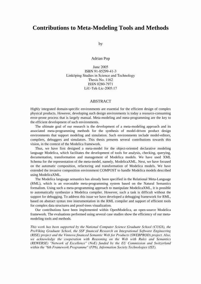
Hardly anyone can speak of general purpose modeling without mentioning the Unified Modeling Language (UML) (OMG [81]). UML is by far the most used specification language used for modeling. UML together with the Meta-Object Facility (MOF) (OMG [84]) forms the bases for Model-Driven Architecture (MDA) (OMG [83]) which aims at unifying the design, development, and integration of system modeling. As an example of this modeling paradigm we can consider the Model Driven Architecture (MDA) (OMG [83]) proposed by Object Management Group. The architecture has four layers, called M0 to M3 presented in Figure 1-1 and below:
• M3 is the meta-metamodel which is an instance of itself. • M2 is the level where the UML meta-model is defined. The concepts used
by the designer, such as Class, Attribute, etc., are defined at this level. • M1 is the level where the UML models reside. • M0 is the level where the actual user objects reside (the world).
An instance at a certain level is always an instance of something defined at one level higher. An actual object at M0 is an instance of a class defined at M1. The classes defined in UML models at M1 are instances of the Class concept defined at

4 Chapter 1 Introduction
M2. The UML meta-model itself is an instance of M3. Other meta-models that define other modeling languages are also instances of M3.
Figure 1-1. The Object Management Group (OMG) 4-Layered
Model Driven Architecture (MDA).
Within the MDA framework, UML Profiles are used to tailor the general UML language to specific areas (domain specific modeling).
Modeling environment configuration approaches similar to the UML Profiles, are present within the Generic Modeling Environment (GME) (Ledeczi et al. 2001 [63], Ledeczi et al. 2001 [64]) which is a configurable toolkit for creating domain-specific modeling and program synthesis environments. Here, the configuration is accomplished through meta-models specifying the modeling paradigm (modeling language) of the application domain.
Computer-aided Multi-paradigm Modeling and Simulation (CaMpaM) (Lacoste-Julien et al. 2004 [60], Lara et al. 2003 [61]) supported by tools such as the ATOM3 environment (A Tool for Multi-formalism and Meta-Modeling) (Vangheluwe and Lara 2004 [124]) is aiming at combining several dimensions of modeling (levels of abstractions, multi-formalisms and meta-modeling) in order to configure environments tailored for specific domains.
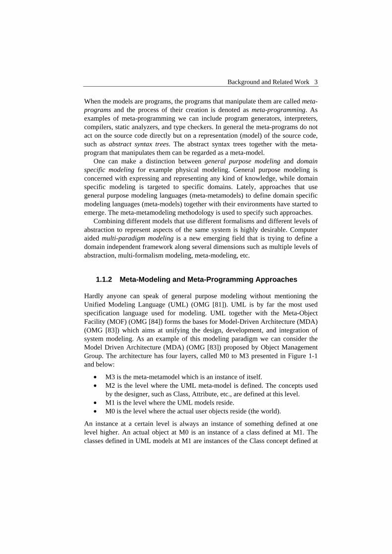
We have already described what meta-modeling and meta-programming are. From another point of view meta-modeling and meta-programming are orthogonal solutions to system modeling (Figure 1-2) that can be combined to achieve model definition and transformation at several abstraction levels
By using meta-programming is possible to achieve transformation between models or meta-models. The meta-models one level up can be used to enforce the correctness of the transformation. Translation and transformation between models
User Objects
Model
Meta-Model
Meta-MetaModel
Level M0
Level M1
Level M2
Level M3 Meta Object Facility (MOF)
The
Mod
elin
g S
pace
UML meta-model, e.g. Class, Interface, Attribute, etc concepts
The actual UML model
Wor
ld
User Objects, actual data
Background and Related Work 5
are highly desired as new models appear and solutions to system modeling require different modeling languages and formalisms together with their environments.
Meta-Modeling
MetaMeta-Model2
Figure 1-2. Meta-Modeling and Meta-Programming dimensions.
1.1.3 Component Models for Invasive Software Composition
The idea that software should be built from existing components appeared in the software community at the end of the 60s, first formulated by Douglas McIlroy (McIlroy 1968 [73]) and had a considerable influence in the software industry.
The most important result of dividing software into relatively independent and adaptable parts is the increased reusability in software development. "Reuse is the use of existing software components in a new context, either elsewhere in the same system or in another system" (Marciniak 1994 [68]). Programmers want a methodology that defines how to reintegrate previously created software into a new context of development, to create software systems from existing software rather than building them from scratch.
Software components are the basic units for software composition. They are designed to be composed; that is, their structure and behavior shall follow specific rules. "A software component is a software element that conforms to a component model and can be independently deployed and composed without modification according to a composition standard." (Heineman and Councill 2001 [50]).
Model1 Model2 ModelN...
Meta-Model1 Meta-Model2
Abs
trac
tion
...
Transformation Meta-Programming

6 Chapter 1 Introduction
A component model defines the external appearance of components that build a system. The component model defines the functionality of the components to be used in composition by explicitly describing component interfaces. A well-designed component model provides support for several important properties of its components, such as:
• Substitution: one component can be replaced by another that fulfills at least the same syntactic or semantic conditions.
• Adaptation: the ability to customize and configure components for different reuse contexts.
• Extension: when new system requirements appear, the extension of existing components should be possible.
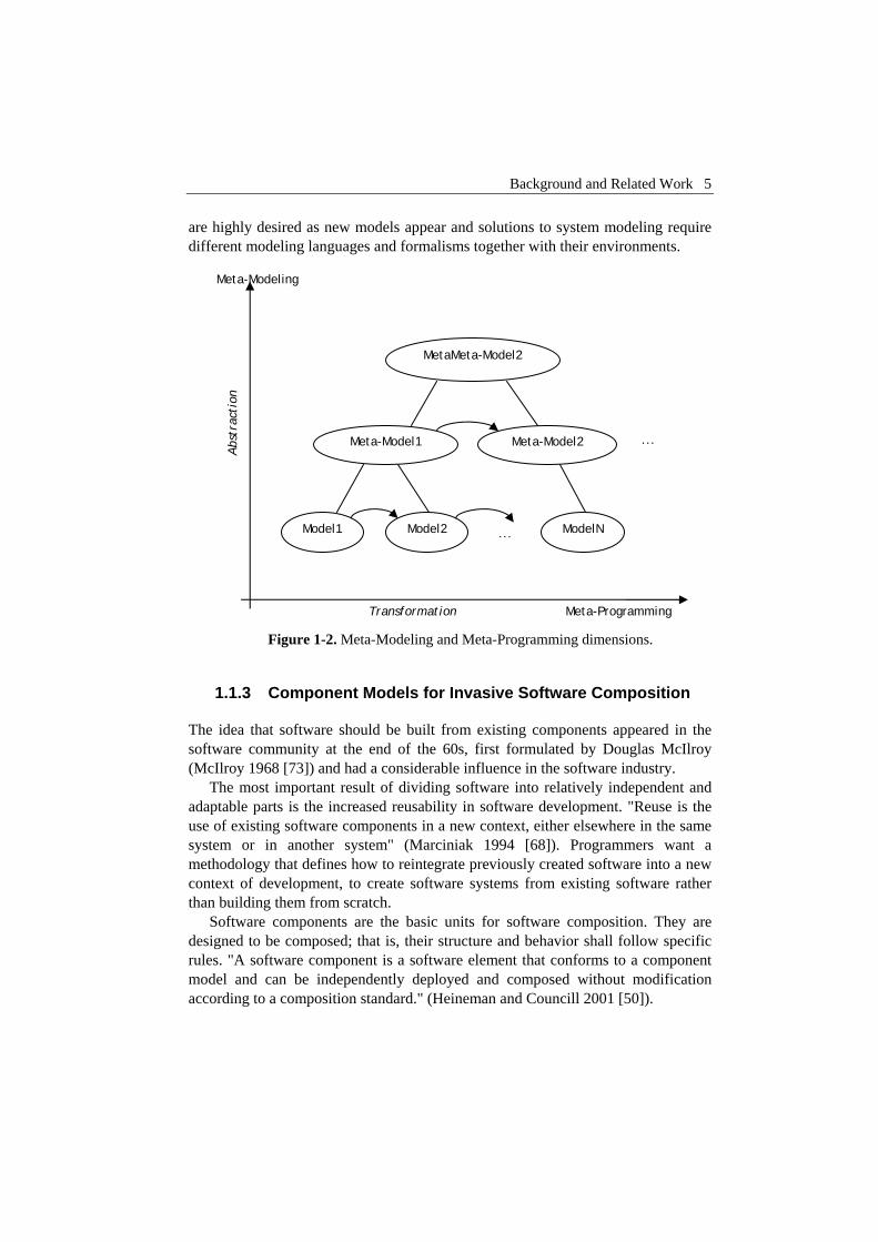
A component model is the core of a component system. In a typical component system, the component model describes components as black boxes, i.e., encapsulated binary code components with completely hidden implementations. The black-box composition method includes various transformations, like adaptation and glue code generation, which essentially compose black boxes without changing their actual content.
Figure 1-3. Black-box vs. Gray-box (invasive) composition. Instead of
generating glue code, composers invasively change the components.
However, in Chapter 3 of this thesis we consider components containing fragments, i.e., pieces of code. As in black-box systems, the contents of the components are hidden under a composition interface. This method is different from black-box composition because the composition operators can invasively change the
Background and Related Work 7
component fragments at predefined points of variability. This reuse abstraction is called grey-box composition and the composition of grey-box components is denoted as invasive software composition (see Figure 1-3).
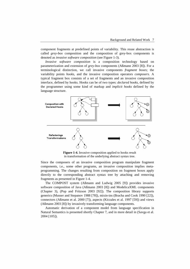
Invasive software composition is a composition technology based on parameterization and extension of grey-box components (Aßmann 2003 [8]). For a terminological distinction, we call invasive components fragment boxes; the variability points hooks, and the invasive composition operators composers. A typical fragment box consists of a set of fragments and an invasive composition interface, defined by hooks. Hooks can be of two types: declared hooks, defined by the programmer using some kind of markup and implicit hooks defined by the language structure.
Figure 1-4. Invasive composition applied to hooks result in transformation of the underlying abstract syntax tree.
Since the composers of an invasive composition program manipulate fragment components, i.e., some other programs, an invasive composition implies meta-programming. The changes resulting from composition on fragment boxes apply directly to the corresponding abstract syntax tree by attaching and removing fragments as presented in Figure 1-4.
The COMPOST system (Aßmann and Ludwig 2005 [9]) provides invasive software composition of Java (Aßmann 2003 [8]) and ModelicaXML components (Chapter 3), (Pop and Fritzson 2003 [92]). The composition library supports generics (Musser and Stepanov 1988 [78]), mixin-ins (Bracha and Cook 1990 [22]), connectors (Aßmann et al. 2000 [7]), aspects (Kiczales et al. 1997 [59]) and views (Aßmann 2003 [8]) by invasively transforming language components.
Automatic derivation of a component model from language specification in Natural Semantics is presented shortly Chapter 7, and in more detail in (Savga et al. 2004 [105]).

8 Chapter 1 Introduction
Using the Extensible Markup Language (XML) (W3C [113]), and the XML Schema (W3C [115]) to model abstract syntax trees (Attali et al. 2001 [10], Attali et al. 2001 [11], Badros 2000 [13], Schonger et al. 2002 [106]) of programming languages is becoming an interesting alternative for having easy access to the structure of programs (in our case models) without the need for a specific parser. We used this approach when designing and defining the meta-model for the Modelica language presented in this thesis. In order to compose and transform models defined by our meta-model we employ invasive software composition (Aßmann 2003 [8]), which is a grey-box component composition. To drive the composition we have designed a component model for our meta-model within the COMPOST system.
1.1.4 The Modelica Language
Modelica (Elmqvist et al. 1999 [33], Fritzson 2004 [39], Modelica-Association 1996-2005 [75], Tiller 2001 [109]) is an object-oriented language for declarative mathematical modeling of large and heterogeneous physical systems. For modeling with Modelica, commercial software products such as MathModelica (MathCore [69]) (Figure 1-5) or Dymola (Dynasim 2005 [30]) have been developed. Also open-source implementations like the OpenModelica system (Fritzson et al. 2002 [37], PELAB 2002-2005 [87]) are available.
Figure 1-5. MathModelica modeling and simulation environment.

Background and Related Work 9
The Modelica language has been designed to allow tools to generate efficient simulation code automatically, with the main objective of facilitating exchange of models, model libraries and simulation specifications. The definition of simulation models is expressed in a declarative manner, modularly and hierarchically. Various formalisms can be combined in the more general Modelica formalism. In this respect, Modelica has a multi-domain modeling capability which gives the user the possibility to combine electrical, mechanical, hydraulic, thermodynamic, etc., model components within the same application model. Compared with most other modeling languages available today, Modelica offers several important advantages from the simulation practitioner's point of view:
• Acausal modeling based on ordinary differential equations (ODE) and differential algebraic equations and discrete equations (DAE). There is also ongoing research to include partial differential equations (PDE) in the language syntax and semantics (Saldamli 2002 [102], Saldamli et al. 2005 [104], Saldamli et al. 2002 [103]).
• Multi-domain modeling capability, which gives the user the possibility to combine electrical, mechanical, thermodynamic, hydraulic etc., model components within the same application model.
• A general type system that unifies object-orientation, multiple inheritance, and generics templates within a single class construct. This facilitates reuse of components and evolution of models.
• A strong software component model, with constructs for creating and connecting components. Thus the language is ideally suited as an architectural description language for complex physical systems, and to some extent for software systems.
The language is strongly typed and there are no side effects of function calls. However, local assignments are allowed in the algorithmic part of the language. The reader of the thesis is referred to any of (Fritzson 2004 [39], Modelica-Association 1996-2005 [75], 2005 [76], Tiller 2001 [109]) for a complete description of the language and its functionality from the perspective of the motivations and design goals of the researchers who developed it. Those interested in shorter overviews of the language may wish to consult (Elmqvist et al. 1999 [33], Fritzson and Bunus 2002 [38], Fritzson and Engelson 1998 [36]).
In this thesis we develop tools for the management of the Modelica models based on meta-modeling and meta-programming approaches. We present a meta-model for the Modelica language structure, invasive composition of Modelica models and integration of Modelica-based modeling and simulation tools with product design tools. Ongoing research (Fritzson et al. 2005 [40]) plans to extend Modelica with meta-modeling and meta-programming features.

10 Chapter 1 Introduction
1.1.5 Integrated Product Design and Development
In the area of model-driven product design using modeling and simulation we focus on the integration of Modelica language with conceptual modeling tools based on Function-Means tree decomposition (Andreasen 1980 [3]).
Designing products is a complex process. Highly integrated tools are essential to help a designer to work efficiently. Designing a product includes early design phase product concept modeling and evaluation, physical modeling and simulation and finally the physical product realization (Figure 1-6). For physical modeling and simulation available tools provide advanced functionality. However, the integration of such tools with conceptual modeling tools is a resource consuming process that today requires large amounts of manual, and error prone work. Also, the number of physical models available to the designer in the product concept design phase is typically quite large. This has an impact on the selection of the best set of component choices for detailed product concept simulation.
To address these issues we have developed a framework (Chapter 4) for product development based on an XML meta-model (Chapter 2), (Pop and Fritzson 2003 [92]) of Modelica and its representation in a Modelica Database (Chapter 4 and 7), (Johansson et al. 2005 [56], Pop et al. 2004 [94]). The product concept design of the product development process is based on Function-Means tree decomposition and is implemented in the FMDesign component (Figure 1-6).
To provide flexibility of the product design framework we have addressed the composition and transformation of Modelica models in the COMPOST framework (Chapter 3), (Pop et al. 2004 [95]).
Figure 1-6. Integrated model-driven product design and development framework.

Background and Related Work 11
Our framework for model-driven product design and development has similarities with Schemebuilder (Bracewell and D.A.Bradley 1993 [21]). The Modelith framework (Johansson et al. 2002 [54], Larsson et al. 2002 [62]) also employs an XML-based model representation for transformation and exchange in physical system modeling.
However, our work is more oriented towards the design of advanced complex products that require systems engineering, and targeted to the simulation modeling language Modelica. The Modelica language has a more expressive power in modeling dynamic systems and system architectures, than many of the tools for systems engineering that are currently used. Also, meta-modeling and invasive software composition methods are considered for automatic model composition and configuration. Tight integration of conceptual modeling tools with modeling and simulation tools is proposed. For details on Systems Engineering, the reader is referred to the International Council on Systems Engineering Website (INCOSE 1990-2005 [53]).
1.1.6 Compiler Construction and Natural Semantics
Writing compilers (Aho et al. 1986 [1], Appel 1997 [4], 2002 [5], Muchnick 1997 [77]) for programming languages is an extremely complex process. One will have to consult the semantics of the language and then implement the compiler in some language of choice. This is a time consuming and error-prone activity. Another approach is to generate parts or the entire compiler from a formal specification (Clément et al. 1986 [26], Despeyroux 1984 [28]). Such approach is highly welcomed and is in the spirit of lexer and parser generators like Lex (Flex) (GNU 2005 [46]) and Yacc (Bison) (GNU 2005 [47]).
From this area we consider the compiler-compiler approach, which generates compilers from formal specifications of programming languages. In particular the work on Natural Semantics (Kahn 1988 [57]), which is a formalism for specifying many aspects of programming languages i.e. type systems, dynamic semantics, translational semantics, static semantics (Despeyroux 1984 [28], Glesner and Zimmermann 2004 [43]), etc. Natural Semantics is an operational semantics derived from the Plotkin (Plotkin 1981 [91]) structural operational semantics combined with the sequent calculus for natural deduction.
One can observe that meta-modeling and meta-programming are also used when constructing compilers:
• A program is a model. • A programming language is a meta-model. • Natural Semantics is a meta-programming formalism used to define the
semantics of meta-models.

12 Chapter 1 Introduction
The Relational Meta-Language (RML) (PELAB 1994-2005 [86], Pettersson 1995 [88], 1999 [90]) is a practical language for writing executable Natural Semantics specifications. The RML language is compiled to highly efficient C code by the rml2c compiler. In this way, large parts of a compiler can be automatically generated from their Natural Semantics specifications. RML has been successfully used at our department in teaching and for specifying and generating compilers from Natural Semantics for Java, Modelica (Fritzson et al. 2002 [37]), MiniML (Clément et al. 1986 [25]) and other languages.
There are few systems implemented that compile or interpret Natural Semantics. One of these systems is Centaur (Borras et al. 1988 [19]) with its implementation of Natural Semantics called Typol (Despeyroux 1984 [28], 1988 [29]). This system is translating the inference rules to Prolog. The RML system is a more efficient implementation of Natural Semantics, with a performance of the generated code that is several orders of magnitude better than Typol.
The RML system had no debugging facilities which made understanding and debugging of the large specifications a challenge. In this context we have developed a debugging framework for RML (Chapter 6), (Pop and Fritzson 2005 [97]) based on abstract syntax tree instrumentation in the RML compiler and support of efficient tools for complex data structures and proof-trees visualization.
A similar approach to debugging is used in debugging Standard ML (Tolmach and Appel 1995 [110]). The idea of having a proof explanation of the reasoning inference has its root in the debugging of deductive databases (Mallet and Ducassé 1999 [67]) and Description Logics reasoning algorithms explanation (McGuinness 1996 [71], McGuinness and Borgida 1995 [70], McGuinness and Silva 2003 [72]). A debugging framework for Natural Semantics can benefit from this work as it must be able to handle large proof-trees and complex data structures.
As a crash course in Natural Semantics and the Relational Meta-Language (RML) we give an example of a small expression (Exp) language and its realization in Natural Semantics and RML. A specification in Natural Semantics has two parts:
• Declarations of syntactic and semantic objects involved. • Groups of inference rules which can be grouped together into relations.
In our example language we have expressions built from numbers. The abstract syntax of this language is declared in the following way:
integers:
expressions (abstract syntax):
:: | 1 2 | 1 2 | 1* 2 | 1 / 2 |
v Int
e Exp v e e e e e e e e e
∈
∈ = + − −

Background and Related Work 13
The inference rules for our language are bundled together in a judgment in the following way (we do not present here the similar rules for the other operators.):
e => v
1 1 2 2 v1+v2 v31 2 3
(1)
(2) e v e ve e v
v v
⇒ ⇒ ⇒
+ ⇒
⇒
The RML modules have two parts, an interface comprising datatype declarations (abstract syntax) and the relation signatures that operate on such datatypes, followed by the declarations of the actual relations which group together rules and axioms. In RML, the Natural Semantics specification presented above is represented as follows:
module exp1: (* Abstract syntax of language Exp1 *) datatype Exp = INTconst of int | ADDop of Exp * Exp | SUBop of Exp * Exp | MULop of Exp * Exp | DIVop of Exp * Exp | NEGop of Exp relation eval: Exp => int end
(* Evaluation semantics of Exp1 *) relation eval: Exp => int = (* Evaluation of an integer node is the integer itself *) axiom eval(INTconst(ival)) => ival (* Evaluation of an addition node ADDop is v3, if v3 is the result of adding the evaluated results of its children e1 and e2. Subtraction, multiplication, etc, operators have very similar specifications. *) rule eval(e1) => v1 & eval(e2) => v2 & v1 + v2 => v3 ----------------------------------------------- eval( ADDop(e1, e2) ) => v3 rule eval(e1) => v1 & eval(e2) => v2 & v1 - v2 => v3 ----------------------------------------------- eval( SUBop(e1, e2) ) => v3

14 Chapter 1 Introduction
rule eval(e1) => v1 & eval(e2) => v2 & v1 * v2 => v3 ----------------------------------------------- eval( MULop(e1, e2) ) => v3 rule eval(e1) => v1 & eval(e2) => v2 & v1 / v2 => v3 ----------------------------------------------- eval( DIVop(e1, e2) ) => v3 rule eval(e) => v & -v => vneg ------------------------- eval( NEGop(e) ) => vneg end (* eval *)
A proof-theoretic interpretation can be assigned to this specification. We interpret inference rules as recipes for constructing proofs. We wish to prove that there is a value such that 1 2 holds for this specification. To prove this proposition we need an inference rule that has a conclusion, which can be instantiated (matched) to the proposition. The only proposition that matches is the second proposition, which is instantiated as follows:
v v+ ⇒
1 1 2 2 1 2
1 2
v v v v
v
⇒ ⇒ + ⇒
+ ⇒
v
To prove further, we need to apply the first proposition (axiom) several times, and we reach the conclusion. One can observe that debugging of Natural Semantics comprise proof-tree understanding and complex data type inspection.
1.1.7 Semantic Web and Description Logics
Recently, in the emerging Semantic Web area (Berners-Lee et al. 2001 [16], SemanticWebCommunity [107], W3C [121], [114]), languages to model ontologies (conceptualization of specific domains) are proposed as a way to add more semantic information (as meta-data) to the existing web data in order to render it usable to machine processing. Until now, the huge amount of information on the web has been designed only for human understanding and had no meaning (semantics) for machines.
The Semantic Web approach is to use meta-languages that markup the existing data on the web with a well-defined meaning in order to allow both machines and humans to process it. There is a vivid debate if ontologies are meta-models or not (Gaševic et al. 2004 [42]). At least from the point of view of knowledge representation and sharing, ontologies and meta-models are trying to tackle the same issues. The Semantic Web provides a common framework that allows data to
Background and Related Work 15
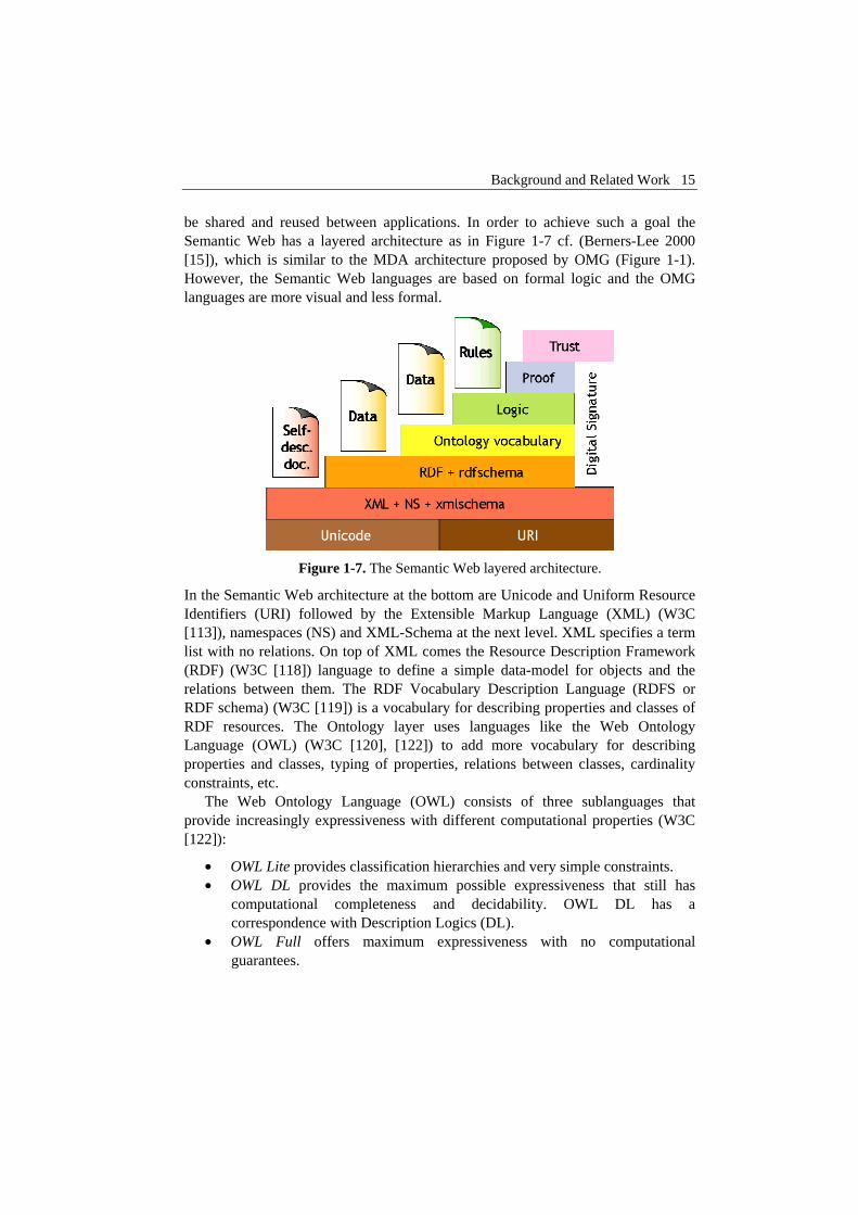
be shared and reused between applications. In order to achieve such a goal the Semantic Web has a layered architecture as in Figure 1-7 cf. (Berners-Lee 2000 [15]), which is similar to the MDA architecture proposed by OMG (Figure 1-1). However, the Semantic Web languages are based on formal logic and the OMG languages are more visual and less formal.
Figure 1-7. The Semantic Web layered architecture.
In the Semantic Web architecture at the bottom are Unicode and Uniform Resource Identifiers (URI) followed by the Extensible Markup Language (XML) (W3C [113]), namespaces (NS) and XML-Schema at the next level. XML specifies a term list with no relations. On top of XML comes the Resource Description Framework (RDF) (W3C [118]) language to define a simple data-model for objects and the relations between them. The RDF Vocabulary Description Language (RDFS or RDF schema) (W3C [119]) is a vocabulary for describing properties and classes of RDF resources. The Ontology layer uses languages like the Web Ontology Language (OWL) (W3C [120], [122]) to add more vocabulary for describing properties and classes, typing of properties, relations between classes, cardinality constraints, etc.
The Web Ontology Language (OWL) consists of three sublanguages that provide increasingly expressiveness with different computational properties (W3C [122]):
• OWL Lite provides classification hierarchies and very simple constraints. • OWL DL provides the maximum possible expressiveness that still has
computational completeness and decidability. OWL DL has a correspondence with Description Logics (DL).
• OWL Full offers maximum expressiveness with no computational guarantees.

16 Chapter 1 Introduction
On top of these ontology languages rules and logic are available to add application behavior.
Description Logics (DL) (Baader et al. 2003 [12], DescriptionLogicsWebsite [27]) is a family of formalisms for representing and reasoning with knowledge. DL is used to represent data and knowledge of the relations between individual objects and their grouping into classes. The DL reasoners (Haarslev et al. 2004 [49], Horrocks [51], W3C [123]) make deductions from a knowledge base of such description of classes and individuals. These deductions are targeted to detect inconsistencies, to classify (organize) the classes into sub-class hierarchies, and to classify individuals under appropriate concepts. DL has also been used to formalize UML models or check their consistency (Berardi et al. 2001 [14]).
In this thesis we discuss the benefits of using Semantics Web languages to construct a better Modelica meta-model in Chapter 2 (Pop and Fritzson 2003 [92]) and present a comparison between meta-models and ontologies in Chapter 5 (Pop and Fritzson 2004 [93]).
1.2 Research topics
Having introduced the related research areas, we present next our thesis goal and motivation, then formulate the two main problems we are addressing.
The ultimate goal of our research is the development of a meta-modeling approach and its associated meta-programming methods for the synthesis of model-driven design environments that support modeling and simulation. Such environments include model-editors, compilers, debuggers and simulators. This thesis presents several contributions towards this vision, in the context of the Modelica framework. To manage this bold vision we have divided it into sub-goals as follows:
• Flexible tool support for management of Modelica models, based on meta-modeling.
• Analysis, composition, refactoring and transformation of Modelica models. • Integration of product design tools with modeling and simulation tools. • Debugging at different levels of abstraction: models, meta-models and
meta-programs (Natural Semantics specifications). • The integration of Natural Semantics (RML) features into a unified
extended Modelica language.
The research work presented in this thesis addresses all these sub-goals of our vision at various depths.

Research topics 17
1.2.1 Design and Application of Meta-Modeling Methods
In this thesis we are interested in the design and application of meta-modeling methods for flexible integration of product design tools with modeling and simulation tools for the Modelica language.
The existing tools for mathematical modeling and simulation of physical systems for the Modelica language are only a small part of a wider picture. Modeling full systems requires integration of different modeling languages, model interoperability, and flexibility. Also, because the Modelica community provides a growing model-base, scalability issues within current tools will create problems of model management. Another issue is that these tools currently provide very little support for integration of their functionality in other modeling frameworks.
A solution for these issues would be a framework based on meta-modeling for Modelica models management with the following requirements:
• Easy and flexible access to model structure and information that would facilitate the creation of tools targeted to different needs than modeling and simulation, e.g. configuration, documentation, enforcing of company guidelines for modeling, etc.
• Means to configure models: composition, refactoring, and transformation (to Modelica or other modeling languages).
• Scalable model-repository search and querying facilities.
In this thesis we present the design and development of a framework that meets these requirements (Chapter 2 to Chapter 4).
1.2.2 Methods and Tools for Debugging of Meta-Programs
Another research topic of our thesis is the design and implementation of methods for debugging of meta-programs expressed as executable Natural Semantics specifications
Writing compilers for programming languages is an extremely complex process. One will have to consult the semantics of the language and then implement the compiler in some language of choice. This is a time consuming and error-prone activity. Another approach is to generate parts or the entire compiler from a formal specification. Such approach is highly welcomed and is in the spirit of lexer and parser generators.
The Relational Meta-Language (RML) system is used to implement the OpenModelica (Fritzson et al. 2002 [37], PELAB 2002-2005 [87]) compiler, a very large specification with: 43 modules, 57083 lines of code, 4054 relations and 132 data structures. Managing this complexity without tool support creates problems of understanding and has made bug fixing in the specification a challenge.

18 Chapter 1 Introduction
To address this problem we have designed and developed a debugging framework for the Relational Meta-Language (Chapter 6). While the debugger framework is far from being optimized, its first users gave us very positive feedback. The debugging approach is mature enough to handle large specification (~57000+ lines of code is our largest specification at the moment).
1.3 Thesis Contributions
In short, the main contributions of this thesis towards the ultimate goal of a general meta-modeling and meta-programming approach for the construction of integrated design environments are the following:
• The design of a meta-model for Modelica language that facilitates development of tools for analysis, checking, querying, documentation, transformation of Modelica models.
• Composition, refactoring and transformation of Modelica models based on a component model for invasive composition of Modelica language and a Modelica meta-model.
• Integration of model-driven product design and development tools with modeling and simulation tools.
• Debugging of meta-programs for programming language semantics specifications written in the Relational Meta-Language dialect of Natural Semantics.
In other words we contribute to the area of meta-modeling and meta-programming with methods and tools that efficiently address the design and usage of meta-models and the debugging of meta-programs.
This thesis is primarily based on the following articles and reports:
2003
1. Adrian Pop, Peter Fritzson: ModelicaXML:A Modelica XML Representation with Applications, In Proceedings of the 3rd International Modelica Conference (Modelica2003), November 3-4, 2003, Linköping, Sweden. (In Chapter 2)
2004
2. Adrian Pop, Ilie Savga, Uwe Aßmann, Peter Fritzson: Composition of XML dialects: A ModelicaXML case study, In Proceedings of the Software Composition Workshop (SC2004), affiliated with European Joint Conferences on Theory and Practice of Software (ETAPS'04), March 27 - April 4, 2004, Barcelona, Spain, Electronic Notes in Theoretical Computer
Thesis Structure 19
Science Volume 114, 17 January 2005, Pages 137-152, http://www.elsevier.com/locate/issn/15710661. (In Chapter 3)
3. Olof Johansson, Adrian Pop, Peter Fritzson: A functionality coverage analysis of industrially used ontology languages, In Proceedings of the Model Driven Architecture: Foundations and Applications (MDAFA2004), June 10-11, 2004, Linköping, Sweden. (In Chapter 7)
4. Adrian Pop, Olof Johansson, Peter Fritzson: An integrated framework for model-driven design and development using Modelica, In Proceedings of SIMS 2004, the 45th Conference on Simulation and Modeling, September 23-24, 2004, Copenhagen, Denmark. (In Chapter 4)
5. Adrian Pop, Peter Fritzson: The Modelica Standard Library as an Ontology for Modeling and Simulation of physical systems, Technical Report, 2004, http://www.ida.liu.se/~adrpo/reports. (In Chapter 5)
6. Ilie Savga, Adrian Pop, Peter Fritzson: Deriving a Component Model from a Language Specification:An Example Using Natural Semantics, Technical Report, 2004, http://www.ida.liu.se/~adrpo/reports. (In Chapter 7)
2005
7. Adrian Pop, Peter Fritzson: A Portable Debugger for Algorithmic Modelica Code, In Proceedings of the 4th International Modelica Conference (Modelica2005), March 7-9 , 2005, Hamburg-Harburg, Germany. (In Chapter 7)
8. Olof Johansson, Adrian Pop, Peter Fritzson: ModelicaDB - A Tool for Searching, Analyzing, Crossreferencing and Checking of Modelica Libraries, In Proceedings of the 4th International Modelica Conference (Modelica2005), March 7-9, 2005, Hamburg-Harburg, Germany. (In Chapter 7)
9. Peter Fritzson, Adrian Pop, Peter Aronsson: Towards Comprehensive Meta-Modeling and Meta-Programming Capabilities in Modelica, In Proceedings of the 4th International Modelica Conference (Modelica2005), March 7-9, 2005, Hamburg-Harburg, Germany. (In Chapter 7)
10. Adrian Pop, Peter Fritzson: Debugging Natural Semantics Specifications, submitted to The Sixth International Symposium on Automated and Analysis-Driven Debugging (AADEBUG 2005), March 2005. (In Chapter 6)
1.4 Thesis Structure
This thesis is structured as a collection of publications, preceded by an introductory chapter. In this section we give a short overview of each of the chapters in the thesis
20 Chapter 1 Introduction
and specify their origin. At the end of this section we also present visually in Figure 1-8 the overview of the structure of this thesis.
Chapters 2 to 6 are faithful reproductions of articles published in conferences and workshops. (We changed the formatting, the cross-references and the literature references were grouped together at the end of the thesis for easy lookup).
Chapter 7 presents short overviews of additional published research that is associated to this thesis work.
Chapter 1 presents a short introduction into the area of modeling, meta-modeling, and meta-programming. Related work and the background for our research work are also introduced here. The chapter presents the research topics we are addressing and our contributions. The conclusions of the thesis, highlights of our contributions and future work directions are presented in the last part of this chapter.
Chapter 2 introduces ModelicaXML, a meta-model for syntactic properties of the Modelica language. This meta-model is an alternative representation of the Modelica language structure in XML format. We show how this meta-model can facilitate the development of tools for querying, transformation, documentation, and analyses of Modelica models. The shortcomings of the proposed Modelica syntactic meta-model are investigated and we discuss how some of the Modelica semantics could be represented using languages and ontologies developed in the Semantic Web.
The ModelicaXML representation provides more functionality than a typical C++ class library implementing an AST representation of Modelica:
• Declarative query languages for XML can be used to query the XML representation.
• The XML representation can be accessed via standard interfaces like Document Object Model (DOM) (W3C [112]) from practically any programming language.
The uses of the ModelicaXML representation for Modelica models, combined with the power of general XML tools, ease the implementation of tasks such as:
• Analysis of Modelica programs (model checkers and validators). • Pretty printing (un-parsing). • Translation between Modelica and other modeling languages (interchange). • Query and transformation of Modelica models. • Documentation generation for models.
Although ModelicaXML captures the structured representation of Modelica source code, the semantics of the Modelica language cannot be expressed without implementing specific XML-based tools. To address this issue we have investigated the benefits of using languages developed in the Semantic Web community. We

Thesis Structure 21
believe that using such technology for Modelica models would enable several applications in the future:
• Models could be automatically translated between modeling tools. • Models could become autonomous (active documents) if they are packaged
together with the operational semantics from the compiler, and therefore, they could be simulated in a normal browser.
• Software information systems (SIS) could be more easily constructed for Modelica, facilitating model understanding and information finding. We consider adapting the approach described in (Welty 1995 [125]) to construct such a SIS for Modelica.
• Model consistency could be checked similar to (Berardi et al. 2001 [14]) using already implemented Description Logic (DL) reasoners i.e. Fact or Fact++ (Horrocks [51]), Racer (Haarslev et al. 2004 [49], W3C [123]), or our implementation. Using our implementation will give us the freedom to experiment with more language constructs and constraints.
• Certain models could be translated to and from the Unified Modeling Language (UML) (OMG [81]).
Chapter 3 presents how invasive composition, refactoring, and transformations can be performed on Modelica models by using the Modelica meta-model and a component model developed for the COMPOST composition framework. The design of the component model for the Modelica meta-model is presented and examples of composition and composition programs are given. This chapter also presents the invasive composition framework COMPOST and investigates how software composition and transformation can be applied to domain specific languages used today in modeling and simulation of physical systems. By extending the COMPOST concrete composition layer with a component model for Modelica, we provide composition and transformation of Modelica models.
Transformation and composition of Modelica models allows easy automatic change of models to fit context. Also, entire systems can be automatically generated, configured, and simulated using a composition language. Such a result gives the framework for product design presented in Chapter 4 a high flexibility and scalability.
Chapter 4 proposes an integrated framework for model-driven product design and development tools (using conceptual design based on Function-Means tree decomposition) with modeling and simulation tools. The Modelica Database component provides scalable querying and analysis facilities for Modelica models. The product concept design of the product development process is based on Function-Means tree decomposition and is implemented in the FMDesign component. The Modelica models are first translated to XML documents conforming to the ModelicaXML meta-model. Then these documents are used to

22 Chapter 1 Introduction
populate the Modelica Database. The goal of this framework is to provide automatic generation of models from product design specifications using a highly integrated set of tools. Another goal is to provide the designer with the possibility of selecting the best design choice, verified through (automatic) simulation of different implementation alternatives of the same product model. To have a flexible interaction among various tools of the framework the ModelicaXML representation of the Modelica language is used as middleware. For efficient searching in large repositories of simulation models the Modelica Database was designed.
As future work we want to explore the use of ontologies for product concept design and for the classification of the available component libraries. For this purpose the languages developed by the Semantic Web community will be used.
This framework is our test-bed for experimenting with novel techniques and methodologies in conceptual design.
Chapter 5 makes a comparison between Modelica Standard Library and ontologies. We discuss on how the features of the declarative Modelica language are contributing to the sharing and reuse of knowledge stored in domain specific libraries and compare this approach with the concept definition approach from ontologies. As an example we present the Modelica Standard Library that defines models in domains such as mechanical, electrical, etc.
Chapter 6 changes the focus of the thesis towards debugging of executable meta-programs used in the specification of programming language semantics. The chapter presents a debugging framework for debugging of Natural Semantics specifications written in the Relational Meta-Language (RML). The debugging strategy and the components of this framework are described in detail together with some usage experience of the debugger on large scale specifications.
Chapter 7 shortly presents additional articles published in cooperation with several authors that are associated with the research work of this thesis. The publications cover:
• Comparisons between industrially used ontology languages as Modelica, UML, and the RosettaNet technical dictionary (RosettaNet [100]).
• Automatic derivation of component models for programming languages that have a Natural Semantics meta-metamodel specified in RML.
• Debugging of Modelica algorithmic code extended with meta-modeling and meta-programming facilities.
• The design and usage of the Modelica Database (ModelicaDB) for storage and management of Modelica model repositories. The detailed UML meta-model for the Modelica Database is presented and use cases of the Modelica Database are discussed.
• The design of Meta-Modeling and Meta-Programming extensions proposed for the Modelica language.

Thesis Structure 23
Figure 1-8. Thesis Structure

24 Chapter 1 Introduction
1.5 Conclusions and Future Work
This last section of the introductory chapter presents our conclusions and our future work directions.
1.5.1 Conclusions
We have designed the ModelicaXML meta-model for Modelica language, which facilitates the development of efficient tools for analysis, checking, querying, documentation, transformation and management of Modelica models. We addressed the automatic composition, refactoring and transformation of Modelica models by extending the invasive composition environment COMPOST with a ModelicaXML component model.
We have integrated Modelica-based modeling and simulation tools with model-driven product design tools within a flexible framework that supports scalable model selection and configuration.
The Modelica language semantics has already been specified in the Relational Meta-Language (RML), which is an executable meta-programming system based on the Natural Semantics formalism. Using such a meta-programming approach to manipulate ModelicaXML, it is possible to automatically synthesize a Modelica compiler. However, such a task is difficult without the support for debugging. To address this issue we have developed a debugging framework for RML, based on abstract syntax tree instrumentation in the RML compiler and support of efficient tools for complex data structures and proof-trees visualization.
Our contributions have been implemented within OpenModelica, an open-source Modelica framework. The evaluations performed using several case studies show the efficiency of our meta-modeling tools and methods. As an overview, in the quest of our research goal, we have touched modeling, meta-modeling, component models for invasive software composition, integration of model-driven product design tool with modeling and simulation tools, debugging of meta-programs expressed in Natural Semantics (Relational Meta-Language). This thesis enters into the details of all these issues and presents several viable solutions.
1.5.2 Future work directions
With the research work presented in this thesis we have made important steps on the way to our research goal. However, our research work will continue along several directions we wish to point out in the following.
We have already started work on extending the Modelica language with Meta-modeling and Meta-programming features (Fritzson et al. 2005 [40]). Such features
Conclusions and Future Work 25
will enable the development of a Modelica compiler written in Modelica and expand the scope of the Modelica language to become a meta-modeling and meta-programming language. The automatic translation of the RML specification of the OpenModelica compiler to the extended Modelica has already been started and we hope that in the near future the Modelica community will contribute to the new compiler.
The debugging framework presented in this thesis has already been adapted to handle Modelica algorithmic code with the new meta-modeling extensions (Pop and Fritzson 2005 [96]). Debugging of the Modelica equation sections is already covered (Bunus 2002 [23], 2004 [24]), and we plan to integrate it with our algorithmic debugging to have a complete debugging framework for Modelica.
Building Natural Semantics and extended Modelica based tools for the Semantic Web with application to model-driven product design will certainly be another future direction of our research. As a starting point we wish to adapt RML to the Natural Semantics specifications of Description Logics (Borgida 1992 [18]).


Chapter 2 ModelicaXML: A ModelicaXML Representation with Applications
Adrian Pop, Peter Fritzson: ModelicaXML:A Modelica XML Representation with Applications, In Proceedings of the 3rd International Modelica Conference (Modelica2003), November 3-4, 2003, Linköping, Sweden
2.1 Abstract
This paper presents the Modelica XML representation with some applications. ModelicaXML provides an Extensible Markup Language (XML) alternative representation of Modelica source code. The language was designed as a standard format for storage, analysis and exchange of models. ModelicaXML represents the structure of the Modelica language as XML trees, similar to Abstract Syntax Trees (AST) generated by a compiler when parsing Modelica source code. The ModelicaXML (DTD/XML-Schema) grammar that validates ModelicaXML documents is introduced. We reflect on the software-engineering analyses one can perform over ModelicaXML documents using standard and general XML tools and techniques. Furthermore we investigate how we can use more powerful markup languages, like the Resource Description Framework (RDF) and the Web Ontology Language (OWL), to express some of the Modelica language semantics.
2.2 Introduction
The structure of a Modelica model can be derived from the source code representation, by using a Modelica compiler front-end (the lexical analyzer and the

28 Chapter 2 ModelicaXML: A ModelicaXML Representation with Applications
parser). The compiler front-end takes the source code representation and transforms it to
abstract syntax trees (AST), which are easier to handle by the rest of the compiler. As pointed out in (Badros 2000 [13]), a clear disadvantage of this procedure is the need of embedding a compiler front-end in every tool that needs access to the structure of the program. Writing such a front-end for an evolving and advanced language like Modelica is not trivial, even with the support of automated tools like Flex (GNU 2005 [46])/Bison (GNU 2005 [47]) or ANTLR (Parr 2005 [85]).
To overcome these problems, a standard, easily used, structured representation is needed. ModelicaXML is such a representation that defines a structure similar to abstract syntax trees using the XML markup language.
This representation provides more functionality than a typical C++ class library implementing an AST representation of Modelica:
• Declarative query languages for XML can be used to query the XML representation.
• The XML representation can be accessed via standard interfaces like Document Object Model (DOM) (W3C [112]) from practically any programming language.
The usages of the ModelicaXML representation for Modelica models, combined with the power of general XML tools, will ease the implementation of tasks like:
• Analysis of Modelica programs (model checkers and validators). • Pretty printing (un-parsing). • Translation between Modelica and other modeling languages (interchange). • Query and transformation of Modelica models.
Although ModelicaXML captures the structured representation of Modelica source code, the semantics of the Modelica language cannot be expressed without implementing specific XML-based tools. To address this issue we have investigated the benefits of using other markup languages like the Resource Description Framework (RDF) and the Web Ontology Language (OWL). These languages, developed in the Semantic Web Community (Berners-Lee et al. 2001 [16], SemanticWebCommunity [107], W3C [121]), are used to express semantics of data in order to be automatically processed by machines. We believe that using such technology for Modelica models would enable several applications in the future:
• Models could be automatically translated between modeling tools. • Models could become autonomous (active documents) if they are packaged
together with the operational semantics from the compiler, and therefore, they could be simulated in a normal browser.
• Software information systems (SIS) could more easily be constructed for Modelica, facilitating model understanding and information finding.

Related Work 29
• Model consistency could be checked using Description Logic (DL) (Baader et al. 2003 [12], DescriptionLogicsWebsite [27]).
• Certain models could be translated to and from the Unified Modeling Language (UML) (OMG [81]).
The paper is structured as follows: Related work is presented in Section 2.3. Modelica, XML and the ModelicaXML Document Type Definition (DTD) are discussed in Section 2.4. In Section 2.5 we present the software-engineering tasks one can perform on the ModelicaXML representation using XML tools and technologies. Section 2.6 investigates the use of RDF and OWL for representing semantics of Modelica models. Conclusions, future research directions and summary of the work are presented in Section 2.7.
2.3 Related Work
In the field of general programming languages, JavaML (Badros 2000 [13]) has been developed as structured representation of Java source code. JavaML emphasizes the power of such structured representation when leveraging XML tools. When it comes to domain specific modeling languages, there are several (Björn et al. 2002 [17], Freiseisen et al. 2002 [34], Larsson et al. 2002 [62]) approaches to specifying models in XML. These approaches deal with model transformation, exchange and management (regarding adaptation to already existing simulation tools) or with code generation from the intermediate XML representation to C++. Our interest focuses more on providing flexible and general software-engineering tooling support for the Modelica programmer. For this purpose the ModelicaXML is covering the full Modelica language (Fritzson 2004 [39], Modelica-Association 1996-2005 [75]), including algorithm sections and expression operators. Furthermore, we consider more powerful markup languages for defining some of the Modelica static semantics and we discuss future use of such Semantic Web technologies.
2.4 Modelica XML Representation
Modelica (Fritzson 2004 [39], Modelica-Association 1996-2005 [75]) is an object-oriented language used for modeling of large and heterogeneous physical systems. For modeling with Modelica, commercial software products such as MathModelica (MathCore [69]) or Dymola (Dynasim 2005 [30]) have been developed. However, there are also open-source projects like the OpenModelica Project (Fritzson et al. 2002 [37], PELAB 2002-2005 [87]). Our research is part of the OpenModelica

30 Chapter 2 ModelicaXML: A ModelicaXML Representation with Applications
Project and aims at providing a more flexible framework with the use of XML technologies.
In sub-section 3.1 we briefly introduce the concepts of XML and DTD and give an example of a Modelica model with its ModelicaXML representation.
2.4.1 The eXtensible Markup Language (XML)
The Extensible Markup Language (XML) (W3C [113]) is a standard recommended by the World Wide Web Consortium (W3C). XML is a simple and flexible text format derived from Standardized Generalized Markup Language (SGML) (W3C [114]). The XML language is widely used for information exchange over the Internet. The tools one can use for parsing, querying, transforming or validating XML documents have reached a mature state. Such tools exist both as open-source projects and commercial software products.
A small example of an XML document is shown below: <?xml version="1.0"?> <!DOCTYPE persons SYSTEM "persons.dtd"> <persons>
<person job="programmer"> <name>John Doe</name> <email> [email protected] </email> </person> ... <person job="manager"> <comment>Classified</comment> </person>
</persons>
An XML document is simply a text in which the information is marked up using tags. The tags are the names enclosed in angle brackets. For easy identification we show elements in bold face and attribute names in italics throughout the XML example. The information delimited by <persons> and </persons> tags is an XML element. As we can see, it can contain other elements called <person> that nests additional elements within itself.
The attributes are specified after the tag as an unordered name/value list of name="value" items. In our example, the attribute job with the value "programmer".
The first line states that this is an XML document. The second line express that an XML parser must validate the contents of the elements against the Document Type Definition (DTD) (W3C [113]) file, here named "persons.dtd". The DTD provides constraints for the contents much like grammars used for programming

Modelica XML Representation 31
languages. There are two criteria to be met in order for an XML document to be valid. First,
all the elements have to be properly nested and must have a start/end tag. Second, all the contents of all elements must obey their DTD grammar specifications.
We will define a DTD for the above example: <!-- the person.dtd file --> <!ENTITY % person-job-attribute "job(programmer|manager) #REQUIRED"> <!ELEMENT persons (person*)> <!ELEMENT person ((name+, email*) | comment+)> <!ATTLIST person project CDATA #IMPLIED &person-job-attribute;> <!ELEMENT name (#PCDATA)> <!ELEMENT email (#PCDATA)> <!ELEMENT comment (#PCDATA)>
The above DTD defines one entity, four elements, and one attribute list containing two attributes. The entities are underlined, bold is used for elements, and attributes are specified in italics.
The entity (ENTITY) declaration defines person-job-attribute as a text value that can be used anywhere inside the DTD and the XML document. The XML parser will replace the entity with its defined text where it is used. The principal element (ELEMENT) declared in DTD is persons and has zero or more elements person nested inside. The special characters inside the element definitions are "*" meaning: zero or more, "|" meaning: selection – either left side or right side, "+" meaning: one or more.
The attribute (ATTLIST) list defines two attributes for the person element: project and job.
The project attribute can contain character data (CDATA) and is optional (#IMPLIED). The job attribute can only have one of the two values, either "programmer" or "manager".
There is another XML document structure standard, called XML-Schema (W3C [115]), which is similar to DTD but is encoded in XML. This standard reconstructs all the capabilities of the DTD and extends them with: namespaces, context sensitivity, the possibility to define several root elements in the same schema, integrity constraints, regular expressions, sub-typing, etc. Tools for transforming XML-Schema representations from/to a DTD representation are available. We use the DTD variant in this example only because it is clearer than the too verbose XML-Schema.
One can consult the World Wide Web Consortium website (W3C [113], [115]) for more information regarding XML, DTD and XML-Schema.

32 Chapter 2 ModelicaXML: A ModelicaXML Representation with Applications
2.4.2 ModelicaXML Example
To introduce the Modelica XML representation, we give a Modelica example and show its corresponding representation as ModelicaXML.
Elements are in bold, attributes are in italic and entities are using underline throughout this section, except from Modelica keywords.
class SecondOrderSystem parameter Real a=1; Real x(start=0); Real xdot(start=0); equation xdot=der(x); der(xdot)+a*der(x)+x=1; end SecondOrderSystem;
For ease of presentation, a ModelicaXML document is split into several parts, each representing a more nested level. The ellipses from one level are detailed in the next level:
<?xml version="1.0" encoding="UTF-8"?> <!DOCTYPE program SYSTEM "ModelicaXML.dtd"> <program within="..."> <definition ident="SecondOrderSystem" restriction="class"> ... </definition> </program>
The root element is a Modelica program. The child elements of program are a sequence of definition elements and an optional within attribute (see Figure 2-1, sub-section 2.4.3 for schemata).
<definition ident="SecondOrderSystem" restriction="class"> <component>...</component> ... <equation>...</equation> ... </definition>
The definition element can have import, extends, elements, equation, or algorithm as sub-elements. In our case we only have component (i.e., variable) and equation sub-elements inside definition (see Figure 2-2, sub-section 2.4.3 for schemata).
<component ident="a" type="Real" variability="parameter" visibility="public"> <modification_equals> <real_literal value="1"/>

Modelica XML Representation 33
</modification_equals> </component> ... <component ident="x" type="Real" visibility="public"> <modification_arguments> <element_modification> <component_reference ident="start"/> <modification_equals> <real_literal value="0"/> </modification_equals> </element_modification> </modification_arguments> </component>
The first component (i.e., variable, see Figure 2-3, sub-section 2.4.3 for schemata) has the variability attribute set to "parameter" as in "parameter Real a=1;". The second component declaration (i.e., variable) in the example represents the "Real x(start=0);" line from our Modelica class. All components have the visibility attribute set to "public". The last component is similar to the second component and is not presented.
<equation> <equ_equal> <component_reference ident="xdot"/> <call> <component_reference ident="der"/> <function_arguments> <component_reference ident="x"/> </function_arguments> </call> </equ_equal> </equation>
Equations are enclosed in the equation element (see Figure 2-4, sub-section 2.4.3 for schemata)
The equation section of the SecondOrderSystem model describes two equations. The first equation is quite straightforward. Equality is represented by an equ_equal element with two elements inside. The right-hand side is a function call (using the call element) to a derivative and the left hand side is a component reference represented with the element with the same name. The second equation below is more complex. It has function calls represented using the call element, binary operations (see Figure 2-6, sub-section 2.4.3 for schemata) such as add, mul for addition (+) and multiplication (*). The component_reference elements denote variable references. For the function calls, the arguments are specified using the element function_arguments that can contain expressions, named arguments or for indices.

34 Chapter 2 ModelicaXML: A ModelicaXML Representation with Applications
<equation> <eq_equal> <add> <call> <component_reference ident="der"/> <function_arguments> <component_reference ident="xdot" /> </function_arguments> </call> <add> <component_reference ident="x"/> <mul> <component_reference ident="a"/> <call> <component_reference ident="der"/> <function_arguments> <component_reference ident="x" /> </function_arguments> </call> </mul> </add> </add> <integer_literal value="1"/> </equ_equal> </equation>
ModelicaXML Schemata are explained in the next sub-section.
2.4.3 ModelicaXML Schema (DTD/XML-Schema)
When designing the ModelicaXML representation we started from the Modelica grammar. We simplified the common cases to compact the XML representation without loss of information or structure. The Modelica DTD/XML-Schema has a rather close correspondence to the Modelica grammar with the following exceptions: attributes are used to make the XML representation more concise and the DTD/XML-Schema jumps over some non-terminals from the Modelica grammar to make the XML representation more compact.
The OpenModelica Project parser for Modelica source code, written in ANTLR (Parr 2005 [85]), was changed to output the ModelicaXML representation. There are many components in the OpenModelica Project that use the ANTLR Modelica parser. Using our ModelicaXML language such tools can be decoupled from this parser. One clear advantage of this approach is that only one parser is maintained and future Modelica language extensions or modifications could be easily integrated.
For presentation purposes we translated our first DTD implementation to XML-Schema using XML Spy (Altova 2005 [2]). The purpose of this translation was to

Modelica XML Representation 35
generate pictures from the XML-Schema. Also, another reason was to have schemata files in both formats for future use. Perhaps, the DTD variant will be discontinued in the future because the XML-Schema is more widely used now.
All elements from our schema have the optional attributes from the location entity (which are sline, scolumn, eline and ecolumn) and the info attribute, which can be used to store additional information. These location attributes are used to generate a mapping between key elements in our schema and the Modelica source code representation. In the following we present some of the important elements from the DTD/XML-Schema.
The content of our ModelicaXML root element, namely program is depicted in Figure 2-1. Inside the root element we can have none or several definition elements. The optional attribute within can be used inside a program element. The rounded corner boxes on the line connecting two elements can be sequence (like in Figure1) or choice (like in the bottom part of Figure 2).
Figure 2-1. The program (root) element of the ModelicaXML Schema.
The required attributes for definition are ident and restriction (which can have one of the "class", "model", "record", "block", "connector", "type", "package", or "function" values). Optional attributes are final, partial, encapsulated, replaceable, innerouter, visibility (one of "public", "protected" values) and string_comment.
The definition element is detailed in Figure 2-2. Presented in the picture at the bottom are the derived element (that handles constructs of the type "class X = Y;") and the enumeration element used to declare enumeration types. The upper part of Figure 2-2 shows the other allowed elements that can appear inside the definition element. All the elements in the upper part have the visibility attribute, taking one of the "public" or "protected" values. The visibility attribute values are stating the "public" or "protected" part from the Modelica source code. We can see that the definition element is recursive, which allows the declaration of classes inside classes.
The definition element can contain import, extends, external, equation, algorithm, annotation and component elements. The latter can use constrain element for handling statements like "type X=Y extends Z;".

36 Chapter 2 ModelicaXML: A ModelicaXML Representation with Applications
Figure 2-2. The definition element from the ModelicaXML Schema.
Component elements, with schemata presented in Figure 2-3, have attributes representing the Modelica type prefix (flow, variability and direction), and type name (type).
The name of the component is stored in the ident attribute. These attributes are important because one can query the ModelicaXML representation for a specific component having desired type and ident. How XML query languages can be used is explained in section 2.5.
The type_array_subscripts element and the array_subscripts element are expressing the fact that Modelica array subscripts can be declared either at the type level or at the component level.

Modelica XML Representation 37
Figure 2-3. The component element from the ModelicaXML Schema.
One can use the element modification_arguments to further modify the component. Comments for a component can be specified with the comment element. The elements modification_equals and modification_assign are used to modify the component; as sub-elements they can have Modelica expressions.
Figure 2-4. The equation element from the ModelicaXML Schema.

38 Chapter 2 ModelicaXML: A ModelicaXML Representation with Applications
An equation element, presented in Figure 2-4, can have initial as an attribute to state if it represents a Modelica initial equation.
The content and the structure of the equation element are closely following the definition from the Modelica Language Specification (Modelica-Association 1996-2005 [75]). The equ_connect element takes component references as arguments here, instead of connect references, as in the version 2.0 of the Modelica Language Specification.
The collapsed parts from the equ_if and equ_when elements are the Modelica expressions, detailed in Figure 2-6. The Modelica expressions are present in the collapsed parts of the algorithm elements alg_if and alg_when and alg_while.
Figure 2-5. The algorithm element from the ModelicaXML Schema.
The algorithm element is presented in Figure 2-5. We point out that the elements alg_break and alg_return are recently added statements of the algorithm section in the latest version (2.1) Modelica Language Specification.
The elements that can appear in ModelicaXML expressions can be found in Figure 2-6. These are binary operations, literals, component references, array constructions, array operators and logical operations.
The constructs from the ModelicaXML schemata not covered here, along with the full "modelicaXML.xsd" (the XML-Schema version) and "modelica-XML.dtd" (the DTD version), can be found at the OpenModelica Project website.

ModelicaXML and XML tools 39
Figure 2-6. The expressions from ModelicaXML schema.
2.5 ModelicaXML and XML tools
This section introduces various XML tools and explains their usage in conjunction with ModelicaXML. In the following, in different sub-sections we cover: the stylesheet language for transformation (XSLT) (W3C [116]), the query language for XML documents (XQuery) (W3C [117]) and the Document Object Model (DOM) (W3C [112]).
2.5.1 The Stylesheet Language for Transformation (XSLT)
XSL is a stylesheet language for XML. XSLT is the part of XSL that deals with transformation of XML documents.

40 Chapter 2 ModelicaXML: A ModelicaXML Representation with Applications
Using XSLT one can implement pretty printers (un-parsers) that can transform ModelicaXML back into Modelica source code. Alternative transformations could transform ModelicaXML into other general, modeling or markup languages (HTML, XHTML, etc). Transformers that translate other modeling languages (provided that they have an XML representation) into ModelicaXML can also be implemented with XSLT. Using XSLT and ModelicaXML, implementation of HTML documentation generators, similar with what the commercial software Dymola provides, becomes trivial. We cannot provide the HTML documentation generator here because of space reasons, but it will be included in the OpenModelica Project.
We illustrate the usage of XSLT with an example that transforms Modelica code. For this example we assume that Modelica code was already translated to ModelicaXML. After the transformation, one can output the Modelica code from the changed ModelicaXML representation using our "modelicaxml-
2modelica.xslt" stylesheet from the OpenModelica Project. Example of changing a component name, both in the declaration of the
component and in the component references: <xsl:stylesheet version="1.0 ..."> <!-- example of component rename --> <xsl:param name="comp_old_name"/> <xsl:param name="comp_new_name"/> <!-- we echo everything that is not a component or a component reference --> <xsl:template match="*|@*|text()"> <xsl:copy> <xsl:apply-templates select="*|@*|text()"/> </xsl:copy> </xsl:template> <!-- we match the old component and we output the new name --> <xsl:template match="component [@ident=$comp_old_name]"> <component ident="{$comp_new_name}"> <xsl:apply-templates/> </component> <!-- we match the old component reference and we output the new component name --> </xsl:template> <xsl:template match="component_reference [@ident=$comp_old_name]"> <component_reference ident="{$comp_new_name}"> <xsl:apply-templates/> </component_reference> </xsl:template> </xsl:stylesheet>

ModelicaXML and XML tools 41
The XSLT engine is using templates that match on the XML tree structure. The matching is performed by the XPath expression appearing as the value of the match attributes. By using xsl:apply-templates element we instruct the XSLT engine to apply the rest of the templates on the sub-tree that we already matched. When this stylesheet is applied on our SecondOrderSystem example from section 2.4.2 with the parameters "xdot" and "xdot_new" it will change the component name and all the component references of xdot to xdot_new.
XSLT can distinguish between components with the same name defined in different classes by the use of XPath expressions. To rename such occurrences we first match the class in which is defined and then the actual component. This applies for both declarations and component references.
A search-and-replace tool could perform this transformation, but such a tool has no knowledge about the context and it will replace even the occurrences appearing inside comments.
2.5.2 The Query Language for XML (XQuery)
XQuery is a query language similar with what SQL is for relational databases. Using XQuery, one can easily retrieve information from XML documents. The XQuery and XSLT are overlapping in some features, and our example could be implemented in XSLT also.
We give a short example of a query over our “SecondOrderSystem.xml” example from section 2.4.2. In words, “find all parameter components with type Real and show the initialization value”:
<table border="1"> { for $b in (document("SecondOrderSystem.xml")/*/ definition/component) where $b/@type = "Real" and $b/@variability="parameter" return <tr><td> { $b/@* } { $b/modification_equals } </td></tr> } </table>
We executed this query in the Qexo (GNU 2005 [44]) implementation of XQuery and the result in HTML is as follows:
<table border="1"> <tr><td> ident="a" type="Real"

42 Chapter 2 ModelicaXML: A ModelicaXML Representation with Applications
variability="parameter" visibility="public" <modification_equals> <real_literal value="1" /> </modification_equals> </td></tr> </table>
As expected, the attributes and the set value of the element corresponding to "parameter Real a=1;" from our Modelica example was returned as the answer.
Using XQuery, any types of queries can be asked about the Modelica model. This opens-up the possibility of easily debugging very large models. User interfaces can be implemented to hide the query building from the user. Static type checking can also be implemented as a series of queries on the model, but is not trivial, because the class hierarchy is not explicitly defined in XML.
XQuery uses XPath as sub-language to select the part of tree that matches the XPath expression. In our XML representation one can match an entire component having a specified ident attribute. The XPath language can be used to handle scooping.
2.5.3 Document Object Model (DOM)
The Document Object Model (DOM) (W3C [112]) is a standard interface that allows programs to access/update the content, structure and style of XML documents. DOM is similar with a general tree-management library.
There are open-source implementations for DOM APIs in Java, C, C++, Perl, Python and other programming languages.
Any Modelica tool written in various programming languages can use the DOM API to directly access/modify the ModelicaXML representation.
2.6 Towards an Ontology for the Modelica Language
This section investigates the possibility of using the markup languages Resource Description Framework (RDF) (W3C [118]), RDF Vocabulary Description Language (RDFS) (W3C [119]) and OWL (W3C [120], [122]) developed in the Semantic Web (Berners-Lee et al. 2001 [16], SemanticWebCommunity [107], W3C [121]) for development of a Modelica ontology.
An ontology is a description (like a formal specification of a program) of both the objects in a certain domain and the relationships between them. In the context of the Semantic Web there is a layered approach for specifying increasingly richer

Towards an Ontology for the Modelica Language 43
semantics for the upper layers as in Figure 2-7.
Figure 2-7. The Semantic Web Layers.
At the bottom, in top of Unicode and Uniform Resource Identifiers (URI) is XML, namespaces (NS) and XML-Schema. XML specifies a term list with no relations. On top of XML comes RDF to define a vocabulary and some relations. RDFS (RDF schema) defines a vocabulary for constructing RDF vocabularies.
The Ontology layer uses languages like OWL to define description logic relationships.
With ModelicaXML we are now only at the XML level! Using RDF we can express graphs and we can model inheritance relationships and place queries over this relation. This can be achieved easily with a smart parser. Using OWL we can place restrictions over relations and concepts and we can reason with inference using Description Logics.
2.6.1 The Semantic Web Languages
This sub-section briefly introduces the Semantic Web Languages: Resource Description Framework (RDF/RDFS) and Web Ontology Language (OWL).
We illustrate the use of Semantic Web Languages by taking a Modelica model and its representation in OWL.
class Body "Generic body" Real mass; String name; end Body; class CelestialBody "Celestial body" extends Body; constant Real g = 6.672e-11; parameter Real radius; end CelestialBody;

44 Chapter 2 ModelicaXML: A ModelicaXML Representation with Applications
CelestialBody moon(name = "moon", mass = 7.382e22, radius = 1.738e6); Body body_instance(name = "some body", mass = 7.382e22);
Our Modelica model has two classes (concepts) Body and CelestialBody the latter being a subclass of the former (by using "extends" statement).
The encoding in OWL is as follows: <?xml version="1.0" ?> <rdf:RDF <!-- namespaces declaration --> xmlns=".../inheritance.owl#" xmlns:modelica=".../inheritance.owl#" xml:base=".../inheritance.owl"> <owl:Ontology rdf:about= ".../inheritance.owl" /> <!-- define Body --> <owl:Class rdf:ID="Body"> <rdfs:label>Generic Body</rdfs:label>
</owl:Class> <!-- define mass -->
<owl:DatatypeProperty rdf:ID="mass"> <rdfs:domain rdf:resource="#Body"/> <rdfs:range rdf:resource="XMLSchema#float"/> </owl:DatatypeProperty> <!-- define name --> <owl:DatatypeProperty rdf:ID="name"> <rdfs:domain rdf:resource="#Body"/> <rdfs:range rdf:resource="XMLSchema#string"/> </owl:DatatypeProperty> <!-- define CelestialBody --> <owl:Class rdf:ID="CelestialBody"> <rdfs:label> Celestial Body </rdfs:label> <rdfs:subClassOf rdf:resource="#Body" /> <!-- cardinality restriction on the g constant: one and only one in CelestialBody --> <rdfs:subClassOf> <owl:Restriction> <owl:onProperty rdf:resource="#g"/>
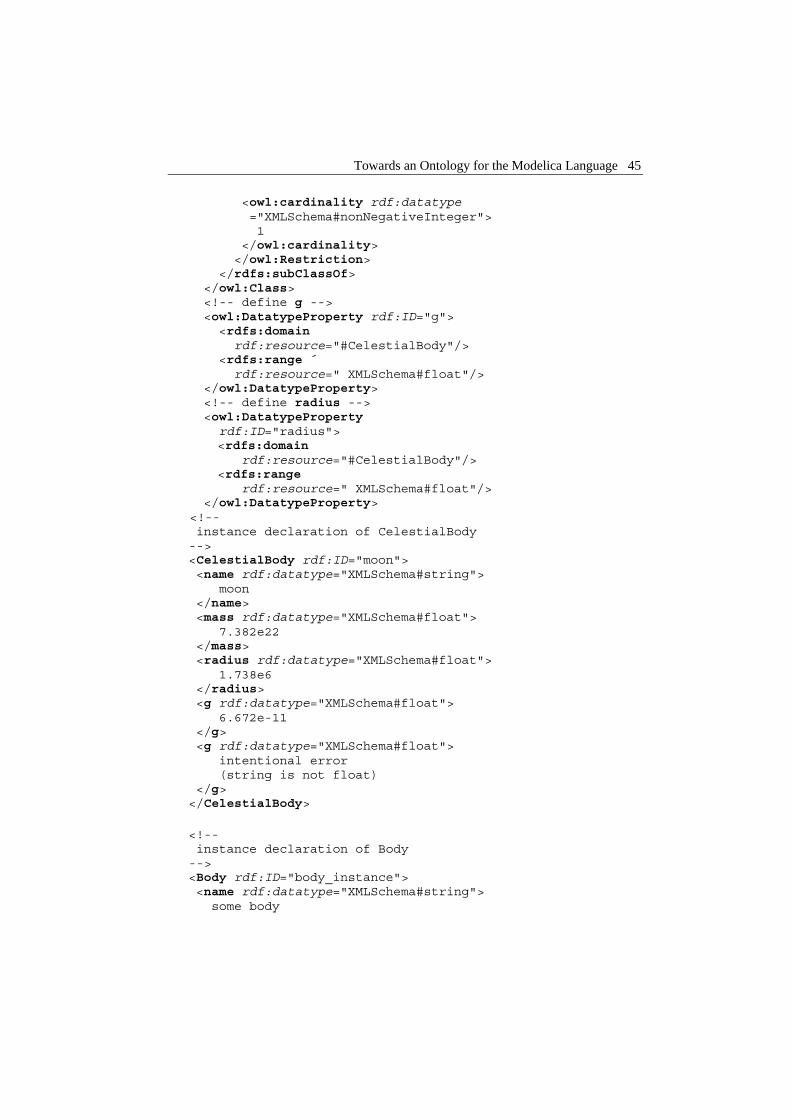
Towards an Ontology for the Modelica Language 45
<owl:cardinality rdf:datatype ="XMLSchema#nonNegativeInteger"> 1 </owl:cardinality> </owl:Restriction> </rdfs:subClassOf> </owl:Class> <!-- define g --> <owl:DatatypeProperty rdf:ID="g"> <rdfs:domain rdf:resource="#CelestialBody"/> <rdfs:range ´ rdf:resource=" XMLSchema#float"/> </owl:DatatypeProperty> <!-- define radius --> <owl:DatatypeProperty rdf:ID="radius"> <rdfs:domain rdf:resource="#CelestialBody"/> <rdfs:range rdf:resource=" XMLSchema#float"/> </owl:DatatypeProperty>
<!-- instance declaration of CelestialBody --> <CelestialBody rdf:ID="moon"> <name rdf:datatype="XMLSchema#string"> moon </name> <mass rdf:datatype="XMLSchema#float"> 7.382e22 </mass> <radius rdf:datatype="XMLSchema#float"> 1.738e6 </radius> <g rdf:datatype="XMLSchema#float"> 6.672e-11 </g> <g rdf:datatype="XMLSchema#float"> intentional error (string is not float) </g> </CelestialBody>
<!-- instance declaration of Body --> <Body rdf:ID="body_instance"> <name rdf:datatype="XMLSchema#string"> some body

46 Chapter 2 ModelicaXML: A ModelicaXML Representation with Applications
</name> <mass rdf:datatype="XMLSchema#float"> 7.382e22 </mass> <-- intentional error (Body does not have a radius) --> <radius rdf:datatype="XMLSchema#float"> 1.738e6 </radius> </Body>
</rdf:RDF>
In the OWL representation of the Modelica model we first define Body as being an owl:Class with "Generic body" as label. The attributes of Body, namely: mass and name are represented as owl:DatatypeProperty. The datatype is a binary relation having a range (type) and a domain (in our case the Body concept). As range we use the datatypes from XML-Schema, in our case, for mass we use "float" and for name we use "string".
The class CelestialBody is defined as owl:subclassOf the Body class according to the "extends" statement from our Modelica model. As an OWL feature in the definition of CelestialBody we show a local cardinality restriction placed on the g relation. This means that in the instances of CelestialBody, the g component has to appear exactly once. The representation of g or radius components is similar to the representation of mass or name.
The moon instance of the CelestialBody class sets the values of the components. We intentionally added the g component twice and with a wrong type. We also declare an instance of the Body class that has a radius component (which is an error).
To verify the model, our file: "inheritance.owl" was fed into an OWL Validator (Rager 2003 [99]).
The validator, as expected, reports the following errors:
• For the g component that has a string as value: “Range Type Mismatch. Use of this property implies that object is of type XMLSchema#float”.
• For the radius component in the body_instance declaration: ”Domain Type Mismatch. Use of this property implies that subject is of type #CelestialBody. Subject is declared type [Body]”
• For the moon instance: “Cardinality Violation. Resource #moon violates the cardinality restriction on class #CelestialBody for property #g. Resource has 2 statements with this property. Maximum cardinality is 1”.
The OWL language has more constructs than our example has covered. One can consult the OWL website (W3C [120], [122]) for more details.

Towards an Ontology for the Modelica Language 47
2.6.2 The roadmap to a Modelica representation using Semantic Web Languages
In the example above we have presented a small ontology that models our Modelica model, consisting of both classes and instances. With a clever parser, such ontologies could be generated from Modelica libraries and then used for composing Modelica models.
The roadmap to a Modelica representation in OWL has the following steps:
• Define an RDFS vocabulary for Modelica source code constructs. Such a vocabulary should include concepts like class, model, record, block, etc.
• Transform the Modelica libraries in their OWL representation using the above vocabulary.
• An OWL validator can then check the correctness of both the concepts and the instances of these concepts.
At the end of this roadmap we would have Modelica represented in OWL. The future benefits of such a representation were underlined in the Introduction section. Here, we briefly explain how they could be achieved.
2.6.2.1 The Autonomous Models
In the OpenModelica Project, the Modelica compiler is built from the formal specification (expressed in Natural Semantics (Kahn 1988 [57])) of the Modelica Language. This specification can be compiled to executable form using the Relational Meta-Language (RML) system (PELAB 1994-2005 [86], Pettersson 1995 [88], 1999 [90]). The rules from Natural Semantics could be translated to OWL or RuleML (RuleML [101]) and shipped together with the model. Using the rules from the model a normal browser could compile and simulate the Modelica model. We assume that the platform should have a C compiler.
2.6.2.2 The Software Information System (SIS)
Having the Modelica ontologies that model the source code one could use the approach detailed in (Welty 1995 [125]) and build the domain model of the problem. Merging them together would result in a Software Information System.
Using such a Software Information System, users can ask queries about the Modelica source code concepts (components, classes, etc) that are classified according to the domain model concepts of the problem.
2.6.2.3 Model consistency could be checked using Description Logic
Modelica models represented in OWL (Description Logics) can be fed into a reasoning tool like FaCT (Horrocks [51]) or Racer (Haarslev et al. 2004 [49]) for consistency checking.

48 Chapter 2 ModelicaXML: A ModelicaXML Representation with Applications
Moreover, such support would be of great help to the Modelica library designers that could formally check relevant properties of the class hierarchies.
The checks one can do using Description Logics on the Modelica OWL representation are the following:
• Ensure that the classes and the class hierarchy are consistent (ensure that a class can have instances and is not over-constrained).
• Find the explicit relations between classes, regarding for example sub-typing or equivalence.
2.6.2.4 Translation of Models to/from Unified Modeling Language (UML)
The UML language has its XML representation called XMI (OMG [82]). Translation from Modelica models conforming to a Modelica ontology to XMI could be possible using XSLT.
2.7 Conclusion and Future work
We have presented the ModelicaXML language and some applications of XML technologies. We have shown that there are some missing capabilities with such XML representation and we addressed some of them. We have presented a roadmap to an alternative representation of Modelica in OWL and the use of representation together with the Semantic Web technology.
As future work, we consider completing the ModelicaXML with the definition of all the intermediate steps representations from Modelica to flat Modelica and further to the code generation. This complete representation would allow various open-source tools to act at these formally defined levels, independent of each other. More information could be added in the future to such XML representation, like: model configuration, simulation parameters, etc.
Further insights in the direction of Semantic Web Languages and their use to express Modelica semantics are necessary. Compilation in both directions between OWL and the Relational Meta-Language (RML) is worth considering.
2.8 Acknowledgements
We would like to thank the anonymous reviewers for their valuable and insightful comments or suggestions.

Chapter 3 Composition of XML dialects: A ModelicaXML case study
Adrian Pop, Ilie Savga, Uwe Aßmann, Peter Fritzson: Composition of XML dialects: A ModelicaXML case study, In Proceedings of the Software Composition Workshop (SC2004), affiliated with European Joint Conferences on Theory and Practice of Software (ETAPS'04), March 27 - April 4, 2004, Barcelona, Spain, Electronic Notes in Theoretical Computer Science Volume 114, Pages 137-152, http://www.elsevier.com/locate/issn/15710661
3.1 Abstract
This paper investigates how software composition and transformation can be ap-plied to domain specific languages used today in modeling and simulation of physical systems. More specifically, we address the composition and transformation of the Modelica language. The composition targets the ModelicaXML dialect which is the XML representation of the Modelica language. By extending the COMPOST concrete composition layer with a component model for Modelica, we provide com-position and transformation of Modelica. The design of our COMPOST extension is presented together with examples of composition programs for Modelica.
Keywords: Composition of XML dialects, XML, Domain Specific Languages, Modelica, ModelicaXML, COMPOST

50 Chapter 3 Composition of XML dialects: A ModelicaXML case study
3.2 Introduction
Modelica (Elmqvist et al. 1999 [33], Fritzson 2004 [39], Modelica-Association 1996-2005 [75], Tiller 2001 [109]) is an object-oriented modeling language used for modeling of multi-domain (i.e. mechanical, electrical, electronic, hydraulic, etc) complex physical systems. Modeling with Modelica has a component-oriented approach where components can be connected together to form a complex system. To have access to the structure of a model, ModelicaXML (Pop and Fritzson 2003 [92]) has been developed as an XML representation (serialization) of Modelica language.
Commercial software products as MathModelica (MathCore [69]) and Dymola (Dynasim 2005 [30]) as well as open-source as OpenModelica System (Fritzson et al. 2002 [37], PELAB 2002-2005 [87]) can be used for modeling with the Modelica language. While all these tools have high capabilities for compilation and simulation of Modelica models, they:
• Provide little support for configuration and generation of components and models from external data sources (databases, XML, etc).
• Provide little support for security, i.e. protection of “intellectual property” through obfuscation of components and models.
• Do not provide automatic composition of models using a composition lan-guage. This would be very useful for automatic generation of models from various CAD products.
• Provide little support for library designers (no automatic renaming of com-ponents in models, no support for comparison of two version of the same component at the structure level, etc)
We address these issues by extending the COMPOST framework with a Modelica component model that acts on the ModelicaXML representation.
The use of XML technology for software engineering purposes is highly present in the literature today. The SmartTools system (Attali et al. 2001 [10], Attali et al. 2001 [11]) uses XML technologies to automatically generate programming environments specially tailored to a specific XML dialect that represents the abstract syntax of some desired language. The use of Abstract Syntax Trees represented as XML for aspect-oriented programming and component weaving is presented in (Schonger et al. 2002 [106]). The OpenModelica System (Fritzson et al. 2002 [37]) project investigates some transformations on Modelica code like meta-programming (Aronsson et al. 2003 [6]). The bases of uniform composition for XML, XHTML dialect and the Java language were developed in the European project Easycomp (EasyComp 2004 [31]). However, the possibilities of this framework can be further extended and tested by supporting composition for an advanced domain specific language like Modelica.

Background 51
The paper is structured as follows. The next section introduces Modelica, ModelicaXML, and COMPOST. Section 3.4 presents our COMPOST extension and its usage through various examples of composition and transformation programs for Modelica. Conclusion and future work can be found in Section 3.5. Section 3.6, the appendix, gives the ModelicaXML representation for some of the examples.
3.3 Background
In this section we briefly introduce the Modelica language and its XML repre-sentation: ModelicaXML, followed by a short description of the COMPOST framework.
3.3.1 Modelica and ModelicaXML
Modelica has a structure similar to the Java language, but with equation and algorithm sections for specifying behavior instead of methods. Also, in contrast to Java, where one would use assignment statements, Modelica is primary an equation-based language. Equations are more powerful than assignments because they do not specify a certain control and data flow direction. Since the flow direction is not explicitly specified, the Modelica classes are more reusable than the classes from traditional programming languages, which use assignment statements for which the data flow direction is always from the right to the left-hand side. We introduce Modelica by an example:
class HelloWorld "HelloWorld comment" Real x(start = 1); parameter Real a = 1; equation der(x) = -a*x; end HelloWorld;
In the example we have defined a class called HelloWorld,which has two components and one equation. The first component declaration (second line) creates a component x, with type Real. All Modelica variables have a start attribute, which can be initialized using a modification equation like (start = 1).
The second declaration declares a so called parameter named a, of type Real and set equal to an integer with value 1. The parameters are constant during simulation; they can be changed only during the set-up phase, before the actual simulation.
The software composition is not performed directly on the Modelica code, but instead, on an alternative representation of it: ModelicaXML (Pop and Fritzson

52 Chapter 3 Composition of XML dialects: A ModelicaXML case study
2003 [92]). As an example, the HelloWorld class translated to ModelicaXML would have the following representation:
<?xml version="1.0" encoding="UTF-8" standalone="no" ?> <!DOCTYPE modelica SYSTEM "modelica.dtd"> <program> <definition ident="HelloWorld" restriction="class" string_comment="HelloWorld comment"> <component visibility="public" type="Real"ident="x"> <modification_arguments> <element_modification> <component_reference ident="start"/> <modification_equals> <integer_literal value="1"/> </modification_equals> </element_modification> </modification_arguments> </component> <component visibility="public" variability="parameter" type="Real" ident="a"> <modification_equals> <integer_literal value="1"/> </modification_equals> </component> <equation> <equ_equal> <call> <component_reference ident="der"/> <function_arguments> <component_reference ident="x"/> </function_arguments> </call> <sub operation="unary"> <mul> <component_reference ident="a"/> <component_reference ident="x"/> </mul> </sub> </equ_equal> </equation> </definition> </program>
The translation of the Modelica into ModelicaXML is straightforward. The abstract syntax tree (AST) of the Modelica code is serialized as XML using the ModelicaXML format. ModelicaXML is validated against the modelica.dtd

Background 53
Document Type Definition (DTD) (W3C [113]). Using the XML representation for Modelica, generation of documentation, translation to/from other modeling languages can be simplified.
3.3.2 Compost
COMPOST is a composition framework for components such as code or document fragments, with special regard to construction time. Its interface layer called UNICOMP for universal composition provides a generic model for fragment components in different languages and different concrete component models. 1
Components are composed by COMPOST as follows. First, the components, i.e., templates containing declared and implicit hooks, are read from file. Then, a composition program in Java applies composition operations to the templates, and transforms them towards their final form. (The transformations rely on standard program transformation techniques.) After all hooks have been filled, the components can be pretty-printed to textual form in a file again. They should no longer contain declared hooks so that they can be compiled to binary form.
3.3.2.1 The notions of components and composition
Fragment-based composition with COMPOST (Aßmann and Ludwig 2005 [9]) is based on the observation that the features of a component can be classified in several dimensions. These dimensions are the language of the component, the model of the component, and abstract component features. The dimensions depend on each other and can be ordered into a layer structure of 5 layers (Figure 3-1):
1. Transformation Engine Layer. The most basic layer encapsulates knowl-edge about the contents of the components, i.e., about the concrete language of the component. Fragment-based component composition needs a transformation engine that transforms the representation of components (Aßmann 2003 [8]). For such transformation engines, COMPOST reuses external tools, such as the Java refactoring engine RECODER (Ludwig [66]). This transformation engine layer contains adapters between COMPOST and the external tools.
2. Concrete Composition Layer. On top of the pure fragment layer, this layer adds information for a concrete component model, e.g., Java fragment components, or ModelicaXML fragment components. Concrete composition constraints are incorporated that describe valid compositions, which can refer to the contents of the components. For instance, a constraint
1 COMPOST and its interface layer UNICOMP can also model runtime and other types of component models, which are not the subject of this paper.

54 Chapter 3 Composition of XML dialects: A ModelicaXML case study
could be defined that disallows to encapsulating a Java method component into another Java method component.
3. Time Specific Composition Layer. On this layer the time of the com-position is taken into account: static or runtime composition.
4. Abstract Composition Layer. In this layer, knowledge is modeled that does not depend on the concrete component language, or on the concrete component model. General constraints are modeled, for instance, that each component has a list of subcomponents, the component hierarchy is a tree, or composition expressions employ the same type of component, independently of the concrete type.
5. UNICOMP Interface Layer. The interfaces of the abstract composition layer have been collected into a separate interface layer, UNICOMP. This set of interfaces provides a generic fragment component model, from which different concrete component models can be instantiated.
Figure 3-1. The layers of COMPOST.
For COMPOST applications, UNICOMP hides underlying concrete information about the component model to a large extent. An application uses COMPOST in a similar way as a component framework with an Abstract Factory (Gamma et al. 1994 [41]). When a component is created, its concrete type is given to the COMPOST factory. However, after creation, the application only uses the UNICOMP generic interfaces. Hence, generic applications can be developed that

Background 55
work for different component models, but use generic composition operations. Already on the Abstract Composition Level, the following uniform operations for fragment components are available:
• Other uniform basic operations. COMPOST composition operators can address hooks and adapt them during composition for a context. As a basic set of abstract composition operators, copy, extend, and rename are available.
• Uniform parameterizations. Template processing works for completely different types of component models. After a semantics for composition points and bind operations has been defined, generic parameterization programs can be executed for template processing.
• Uniform extensions. The extension operator works on all types of com-ponents.
• Uniform inheritance. On the abstract composition layer COMPOST defined several inheritance operators that can be employed to share components, be it Java, or XML-based components. Inheritance is explained as a copy-and-extend operation, and both copy and extend operations are available in the most abstract layer.
• Uniform connection. COMPOST allows for uniform connection operations, as well for topologic as well as concrete connections (Aßmann 2003 [8]).
• Uniform aspect weaving. Based on these basic uniform operations, uniform aspect weaving operations (Karlsson 2003 [58]), can be defined.
The great advantage of the layer structure is that new component models, e.g., for XML languages, can be added easily as we show in this paper. In fact, COMPOST is built for extension: adding a new component model is easy, it consists of adding appropriate classes in the concrete composition levels, subclassing from the abstract composition level as we show in Section 3.4.
3.3.2.2 Composition Constraints
Each COMPOST layer contains constraints for composition. These constraints consist of code that validates components and compositions.
• Composite component constraints. A component must be composite, i.e., the composed system is a hierarchy of subsystems. A component is the result of a composite composition expression or a composition program.
• Composition typing constraints. Composition operations must fit to com-ponents and their composition points. For instance, a composer may only bind appropriate values to composition points (fragments to fragments, runtime values to runtime values), or use a specific extension semantics.
• Constraints on the content of components. For instance, for a Java com-position system, this requires that the static semantics of Java is modeled,

56 Chapter 3 Composition of XML dialects: A ModelicaXML case study
and that this semantics controls the composition. For an XML dialect, semantic constraints can be modeled, for instance, that all links in a doc-ument must be valid, i.e., point to a reasonable target. Our extended framework presented in this paper provides parts of the Modelica semantics in top of the ModelicaXML format.
With these constraints, it should be possible to type-check composition expressions and programs in the UNICOMP framework. Many of these constraints can be specified in a logic language, such as first order logic (Datalog) or OWL (W3C [122]), and can be generated to check objects on every layer.
3.3.2.3 Support for staged composition
COMPOST supports staged composition as follows. Firstly, the UNICOMP layer has been connected to the Component Workbench, the visual component editor of the VCF (Oberleitner and Gschwind 2002 [80]). Composition programs for fragment component models can be edited from the Component Workbench, and executed via COMPOST.
So far, a case study has been build for a web-based conference reviewing system that requires Java and XHTML composition. This paper shows how to compose Modelica components by using its alternative XML representation: ModelicaXML.
Secondly, COMPOST can be used to prepare components such that they fit into component models of stage 2 and 3. For instance, COMPOST connectors can prepare a Java class for use in CORBA context (Aßmann et al. 2000 [7]). They can also be used to insert event-emitting code, to prepare a class for Aspect-Oriented Programming.
3.4 COMPOST extension for Modelica
This section describes the Modelica component model. The architecture of our system is presented. Modelica Box and Hook hierarchies are explained. Finally, various composition programs are given as examples.
3.4.1 Overview
The architecture of the composition system is given in Figure 3-2. A Modelica parser is employed to generate the ModelicaXML representation. ModelicaXML is fed into the COMPOST framework where it can be composed and transformed. The result is transformed back into Modelica code by the use of a ModelicaXML unparser.
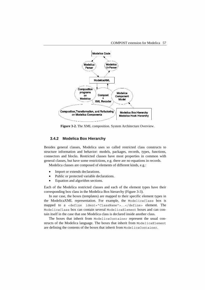
COMPOST extension for Modelica 57
Figure 3-2. The XML composition. System Architecture Overview.
3.4.2 Modelica Box Hierarchy
Besides general classes, Modelica uses so called restricted class constructs to structure information and behavior: models, packages, records, types, functions, connectors and blocks. Restricted classes have most properties in common with general classes, but have some restrictions, e.g. there are no equations in records.
Modelica classes are composed of elements of different kinds, e.g.:
• Import or extends declarations. • Public or protected variable declarations. • Equation and algorithm sections.
Each of the Modelica restricted classes and each of the element types have their corresponding box class in the Modelica Box hierarchy (Figure 3-3).
In our case, the boxes (templates) are mapped to their specific element types in the ModelicaXML representation. For example, the ModelicaClass box is mapped to a <define ident="ClassName">..</define> element. The ModelicaClass box can contain several ModelicaElement boxes and can con-tain itself in the case that one Modelica class is declared inside another class.
The boxes that inherit from ModelicaContainer represent the usual con-structs of the Modelica language. The boxes that inherit from ModelicaElement are defining the contents of the boxes that inherit from ModelicaContainer.

58 Chapter 3 Composition of XML dialects: A ModelicaXML case study
The boxes incorporate constraints derived from Modelica static semantics. For example, constraints specify that inside a ModelicaRecord is not allowed to have ModelicaEquationSections.
Figure 3-3. The Modelica Box Hierarchy defines
a set of templates for each language structure.
While these constraints in our case were specified in the Java code, a future extension will automatically generate these constraints from external specifications expressed in formalisms such as Document Type Definition (DTD) (W3C [113]), Web Ontology Language (OWL) (W3C [120], [122]) or Relational Meta-Language (RML) (PELAB 1994-2005 [86], Pettersson 1995 [88], 1999 [90]).
3.4.3 Modelica Hook Hierarchy
Implicit Hooks are fragments of Modelica classes that have specific meaning according to Modelica code structure and semantics. By using Hooks one can easily change/extract parts of the code. In the Modelica Hook Hierarchy presented in (Figure 3-4) only Implicit Hooks are defined for the Modelica code.
There is no need to define Declared Hooks especially for Modelica, because the XMLDeclaredHook already performs this operation. One can have an XML de-clared hook that extracts from the XML document the contents of an element with a specified tag, i.e., <extract ...>.
Hooks are used to configure parts of boxes. The XMLImplicitHook is specialized as ModelicaParameterHook or ModelicaModificationHook.
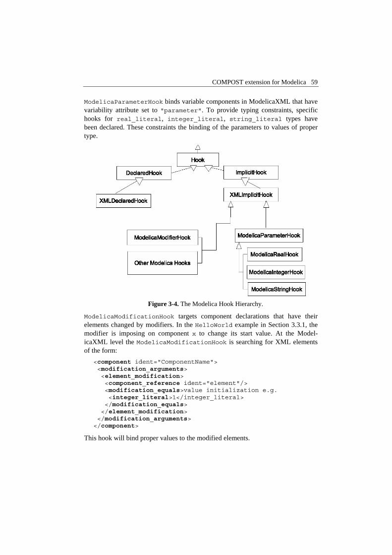
COMPOST extension for Modelica 59
ModelicaParameterHook binds variable components in ModelicaXML that have variability attribute set to "parameter". To provide typing constraints, specific hooks for real_literal, integer_literal, string_literal types have been declared. These constraints the binding of the parameters to values of proper type.
Figure 3-4. The Modelica Hook Hierarchy.
ModelicaModificationHook targets component declarations that have their elements changed by modifiers. In the HelloWorld example in Section 3.3.1, the modifier is imposing on component x to change its start value. At the Model-icaXML level the ModelicaModificationHook is searching for XML elements of the form:
<component ident="ComponentName"> <modification_arguments> <element_modification> <component_reference ident="element"/> <modification_equals>value initialization e.g. <integer_literal>1</integer_literal> </modification_equals> </element_modification> </modification_arguments> </component>
This hook will bind proper values to the modified elements.

60 Chapter 3 Composition of XML dialects: A ModelicaXML case study
Also, other types of implicit hooks can be specified like hooks for the left hand side or the right hand side of an equation hooks that change types of components, hooks that change the documentation part of a class declaration, etc.
3.4.4 Examples of composition and transformation programs
This subsection gives concrete examples on the usages of our framework. The examples are written in Java, but they could easily be performed using a tool that has visual abstractions for the composition operators. For presentation issues only the Modelica code is given in the examples below and their corresponding ModelicaXML representation is presented in Section 3.6.
3.4.4.1 Generic parameterization with type checking
To be able to reuse components into different contexts they should be highly configurable. Configuration of parameters in Modelica is specified in class definitions and can be modified in parameter declaration. The values can be read from external sources using external functions implemented in C or Fortran. In the example below we show how the parameters of a Modelica component can be configured using implicit hooks. Because we use Java, the parameter/value list can be read from any data source (XML, SQL, files, etc). The example is based on the following Modelica class:
class Engine parameter Integer cylinders = 4; Cylinder c[cylinders]; /* additional parameters, variables and equations */ end Engine;
Different versions of the Engine class can be automatically generated using a composition script. Also, the parameter values are type checked before they are bound to ensure their compatibility. The composition script is given below partially in Java, partially in pseudo-code:
ModelicaCompositionSystem cs = new ModelicaCompositionSystem(); ModelicaClass templateBox = cs.createModelicaClass("Engine.mo.xml"); /* read parameters from configuration file, XML or SQL */ foreach engine entry X { ModelicaClass engineX = templateBox.cloneBox().rename("Engine_"+X);
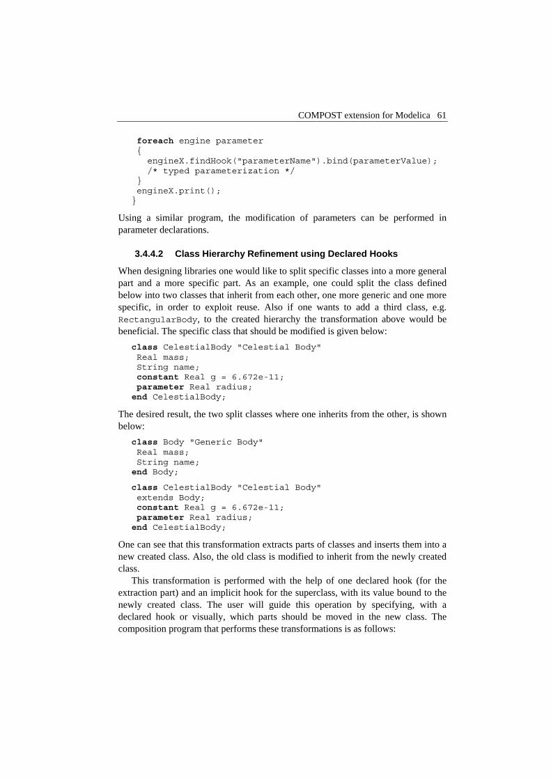
COMPOST extension for Modelica 61
foreach engine parameter { engineX.findHook("parameterName").bind(parameterValue); /* typed parameterization */ } engineX.print(); }
Using a similar program, the modification of parameters can be performed in parameter declarations.
3.4.4.2 Class Hierarchy Refinement using Declared Hooks
When designing libraries one would like to split specific classes into a more general part and a more specific part. As an example, one could split the class defined below into two classes that inherit from each other, one more generic and one more specific, in order to exploit reuse. Also if one wants to add a third class, e.g. RectangularBody, to the created hierarchy the transformation above would be beneficial. The specific class that should be modified is given below:
class CelestialBody "Celestial Body" Real mass; String name; constant Real g = 6.672e-11; parameter Real radius; end CelestialBody;
The desired result, the two split classes where one inherits from the other, is shown below:
class Body "Generic Body" Real mass; String name; end Body;
class CelestialBody "Celestial Body" extends Body; constant Real g = 6.672e-11; parameter Real radius; end CelestialBody;
One can see that this transformation extracts parts of classes and inserts them into a new created class. Also, the old class is modified to inherit from the newly created class.
This transformation is performed with the help of one declared hook (for the extraction part) and an implicit hook for the superclass, with its value bound to the newly created class. The user will guide this operation by specifying, with a declared hook or visually, which parts should be moved in the new class. The composition program that performs these transformations is as follows:

62 Chapter 3 Composition of XML dialects: A ModelicaXML case study
ModelicaCompositionSystem cs = new ModelicaCompositionSystem(); ModelicaClass bodyBox = cs.createClass("Body.mo.xml"); ModelicaClass celestialBodyBox = cs.createModelicaClass("Celestial.mo.xml"); ModelicaElement extractedPart = celestialBody.findHook("extract").getValue(); /* empty the hook contents */ celestialBody.findHook("extract").bind(null); bodyBox.append(extractedPart) bodyBox.print(); celestialBody.findHook("superclass").bind("Body"); /* or findSuperclass().bind("Body"); */ celestialBody.print();
Similar transformations can be used to compose Modelica models based on the interpretation of other modeling languages. During such composition some classes need to be wrapped to provide a different interface. For example, when there is only a force specified for moving a robot arm, but the available library of components only provides electrical motors that generate a force proportional to a voltage input.
3.4.4.3 Composition of classes or model flattening
Mixin composition of the entire contents of two or more classes into one another is performed when the models are flattened i.e. as the first operation in model obfuscation or at compilation time. The content of the classes composed below is not relevant for this particular operation. The composition program that encapsulates this behavior is as follows:
ModelicaCompositionSystem cs = new ModelicaCompositionSystem(); ModelicaClass resultBox = cs.createModelicaClass("Class1.mo.xml"); ModelicaClass firstMixin = cs.createModelicaClass("Class2.mo.xml"); ModelicaClass secondBox = cs.createModelicaClass("Result.mo.xml"); resultBox.mixin(firstMixin); resultBox.mixin(secondMixin); resultBox.print();
It first reads the two classes from files, creates a new result class and pastes the contents of the first classes inside the new class.

Conclusion and Future work 63
3.5 Conclusion and Future work
We have shown how composition on Modelica, using its alternative the Model-icaXML representation, can be achieved with a small extension of the COMPOST framework. While this is a good start, we would like to extend our work in the future with some additional features like:
• More composition operators and more transformations, i.e., obfuscation, symbolic transformation of equations, aspect oriented debugging of compo-nent behavior by weaving assert statements in equations, etc.
• Implementation of full Modelica semantics to guide the composition, based on the already existing Modelica compiler implemented in the OpenModelica System.
• Validation of the composed or transformed components with the OpenModelica compiler.
• Automatic composition of Modelica models based on interpretation of other modeling languages.
Modelica should provide additional constraints on composition, based on the domain knowledge. These constraints are specifying, for example, that specific components should not be connected even if their connectors allow it. We would like to further investigate how these constraints could be specified by library developers.
3.6 Appendix
CelestialBody in ModelicaXML format before transformation: <definition ident="CelestialBody" restriction="class" string_comment="Celestial Body"/> <component visibility="public" ident="mass" type="Real"/> <component visibility="public" ident="name" type="String"/> <component visibility="public" variability="constant" ident="g" type="Real"> <modification_equals> <real_literal value="6.672e-11"/> </modification_equals> </component> <component visibility="public" variability="parameter" ident="radius" type="Real"/> </definition>

64 Chapter 3 Composition of XML dialects: A ModelicaXML case study
CelestialBody and Body in ModelicaXML format after transformation: <definition ident="Body" restriction="class" string_comment="Generic Body"/> <component visibility="public" ident="mass" type="Real"/> <component visibility="public" ident="name" type="String"/> </definition>
<definition ident="CelestialBody" restriction="class" string_comment="Celestial Body"/> <extends type="Body"/> <component visibility="public" variability="constant" ident="g" type="Real"> <modification_equals> <real_literal value="6.672e-11"/> </modification_equals> </component> <component visibility="public" variability="parameter" ident="radius" type="Real"/> </definition>
The Engine class representation in ModelicaXML: <definition ident="Engine" restriction="class"> <component visibility="public" variability="parameter" type="Integer" ident="cylinders"> <modification_equals> <integer_literal value="4"/> </modification_equals> </component> <component visibility="public" type="Cylinder" ident="c"> <array_subscripts> <component_reference ident="cylinders"/> </array_subscripts> </component> </definition>

Chapter 4 An Integrated Framework for Model-driven Product Design and Development Using Modelica
Adrian Pop, Olof Johansson, Peter Fritzson: An integrated framework for model-driven design and development using Modelica, the 45th Conference on Simulation and Modeling (SIMS 2004), September 23-24, 2004, Copenhagen, Denmark.
4.1 Abstract
This paper presents recent work in the area of model-driven product development processes. The focus is on the integration of product design tools with modeling and simulation tools. The goal is to provide automatic generation of models from product specifications using a highly integrated set of tools. Also, we provide the designer with the possibility of selecting the best design choice, verified through (automatic) simulation of different implementation alternatives of the same product model. To have a flexible interaction among various tools of the framework an XML representation of the Modelica modeling language called ModelicaXML is used. For efficient search in a large base of simulation models the Modelica Database was designed.
4.2 Introduction and Related Work
Designing products is a complex process. Highly integrated tools are essential to help a designer to work efficiently. Designing a product includes early design phase

66 Chapter 4 An Integrated Framework for Model-driven Product Design
product concept modeling and evaluation, physical modeling and simulation and finally the physical product realization. For conceptual modeling and physical modeling and simulation available tools provide advanced functionality. However, the integration of such tools is a resource consuming process that today requires large amounts of manual, and error prone work. Also, the number of physical models available to the designer in the product concept design phase is typically quite large. This has an impact on the selection of the best set of component choices for detailed product concept simulation.
To address these issues we have integrated new product concept design tools with physical modeling and simulation tools in a framework for product design. In our proposed framework, the product concept design phase of the product development process is based on Function-Means tree decomposition (Andreasen 1980 [3]). This phase is implemented in a first version of a prototype tool called FMDesign, developed in cooperation with the Machine Design Group led by Petter Krus, IKP, Linköping University.
As an example of Function-Means tree decomposition we give a landing function in an airplane. This function can be represented by two different means: hydraulic landing gear or electric landing gear. Each of the two alternatives can be selected and configured to simulate its properties.
Starting from FMDesign tool, our integration work extends the framework in two ways:
• Providing a Selection and Configuration Tool that helps the designer to choose a specific implementation for the means in the function-means tree from a Modelica model/ component database. This tool also provides component configuration and has links to a Modelica standard based simulation environment for component editing.
• Providing an Automatic Model Generation Tool that helps the designer to choose the best implementation from different design choices by evaluation through simulation of automatically generated models of candidate product concepts. If the designer is not pleased with the results, he/she can either implement new models for the components that did not perform in the desired way or reiterate in the design process and choose other alternatives for implementing different functions in the product, or change the configuration parameters for models at deeper levels of detail.
The paper is structured as follows: The next section (section 4.3) presents an overview of our proposed framework. Section 4.4 enters in the details of the framework components and their interaction. Section 4.5 presents our conclusion and future work.
The presented system has similarities with the Schemebuilder tool (Bracewell and D.A.Bradley 1993 [21]) and Modelith framework (Johansson et al. 2002 [54], Larsson et al. 2002 [62]). However our work is more oriented towards the design of

Architecture overview 67
advanced complex products that require systems engineering, and targeted to the simulation modeling language Modelica, which to our knowledge has more expressive power in the areas of our research, than many tools for systems engineering that are currently widely used. For details on Systems Engineering, see (INCOSE 1990-2005 [53]).
4.3 Architecture overview
The architecture of our extended framework is presented in Figure 4-1. The entire product concept design process is iterative.
EngineeringDesign
System X
Product ConceptDesign Tool
(FMDESIGN)
Requirements Database
F1 M1a M1b M1c
F1a.1 F1a.2 F1a.3
ModelicaXMLGeneratedModels
Simulation Evaluation
Optimisation
Modelica Simulation Source code
MeansEvaluations
OperationCases
Product Concept Design Database
Reference Links
F = FunctionM = Means
Modelica Model Database
Selection and Configuration Tool
AutomaticModel
GeneratorTool
Figure 4-1. Design framework for product development.
Starting from requirements for a product the designer will use the FMDesign prototype for modeling alternative product concepts. The knowledge base for designing a product is organized into function-means trees. A function in the product can be realized by alternative means. A product concept is a set of means that document selected solution alternatives for implementing the functions in a product concept. Example of a function is "Actuator Power Supply", with means "Hydraulic Power Supply" or "Electrical Power Supply".

68 Chapter 4 An Integrated Framework for Model-driven Product Design
Means must be implemented by (physical) components arranged in a bill-of-material like tree of implementation objects.
One can roughly say that a means and its implementation are the same, but at different levels of detail. Implementation objects (not shown in the figure) may represent existing component products on the market or manufactured components. Implementation objects carry data that is important for the product concept design, and references to more detailed design information like CAD-drawings, simulation models etc. Some (physical components) may implement several means, like an aircraft wing that creates lift and stores fuel.
To map suitable simulation model implementations to a means, the designer would use the Modelica Database query facility provided by the Selection and Configuration Tool. This tool also provides configuration of the simulation components and uses the desired Modelica environment for component editing.
When the product concept design phase of the product is sufficiently complete, the designer can generate code for simulation from the implementation tree using the Automatic Model Generator Tool. The generator will output models (different versions for different product concepts) in ModelicaXML. From Modelica-XML the models are translated to Modelica to be simulated. The designer can review the simulation results in tools like MathModelica (MathCore [69]), Dymola (Dynasim 2005 [30]) or OpenModelica (Fritzson et al. 2002 [37], PELAB 2002-2005 [87]) and then selects (in FMDesign) the desired model alternative for the implementation. If the designer sees that some means do not perform in the desired way, a customized simulation model can be built, or a search conducted for more alternatives for that specific means.
4.4 Detailed framework description
In this section we present the tools from our proposed framework. Also, we briefly explain in each section how they interact.
4.4.1 ModelicaXML
Modelica (Fritzson 2004 [39], Modelica-Association 1996-2005 [75]) is an object-oriented language used for modeling of large and heterogeneous physical systems. For modeling with Modelica, commercial software products such as MathModelica (MathCore [69]) or Dymola (Dynasim 2005 [30]) have been developed. However, there are also open-source projects like the OpenModelica Project (Fritzson et al. 2002 [37], PELAB 2002-2005 [87]).
Modelica is translated to ModelicaXML (Pop and Fritzson 2003 [92]) using a Modelica parser (Figure 4-2).

Detailed framework description 69
Modelicacode
ModelicaXML
Modelica Parser
read
output
class Test "comment"
Real x;
Real xdot;
equation
xdot = der(x);
end Test;
<modelicaxml>
<definition ident= "Test"
comment="comment">
<component ident="x" type="Real"
visibility="public" />
<component ident="xdot" type="Real"
visibility="public" />
<equation>...</equation>
</definition>
</modelicaxml>
modelicaxml
definition
component
component
equation
Figure 4-2. Modelica and the corresponding ModelicaXML representation.
ModelicaXML represents an XML serialization of the Abstract Syntax Tree of the Modelica language obtained after the parsing. In our framework, ModelicaXML is used as an interchange format between the different design tools.
The advantages of having an alternative representation for Modelica in XML are:
• Flexible interaction and translation between different types of physical modeling languages and modeling tools. Also, easy generation of model documentation.
• Basic search and query functionalities over models. • Easy transformation and composition of models (Pop et al. 2004 [95]).
For more information on ModelicaXML the reader is referred to (Pop and Fritzson 2003 [92]) and (Fritzson 2004 [39]).
4.4.2 Modelica Database (ModelicaDB)
The features of the Modelica language and Modelica tools has made easy for designers to create models. Also, the Modelica community has a growing code-base. In order to cope with interoperability between Modelica and other modeling languages we first developed ModelicaXML. However, scalability and efficient

70 Chapter 4 An Integrated Framework for Model-driven Product Design
search features for XML require extensive skills in vendor specific products. To quickly get such features without taking on that huge learning effort, we have designed the Modelica Database (ModelicaDB).
The Modelica Database is populated with Modelica models and libraries by importing their ModelicaXML representation. The UML model of this database is presented in the appendix (section 4.7). For paper space reasons we use a somewhat customized compressed graphical representation of UML class diagrams, where inheritance is represented with a box between the class name and attributes box, where inherited super classes are preceded with a "->". For details on UML see (OMG [81]).
Here we briefly explain the most important structures. They are tightly coupled with the Modelica structure (Fritzson 2004 [39], Pop and Fritzson 2003 [92]):
• Modelica Repository: contains several Modelica Models. • Class: A class represents the fundamental model element from the Modelica
language. It can include several Component clauses, Equation and Algorithm statements. The component sections can be declared as public or protected in order to provide only the desired interface to the outer world. Specifying that the equation or algorithm sections are only active at the initialization phase they can be declared as initial.
• Component: used to define parameters, variables, constants, etc to be used inside a class.
• Equations and Algorithms are used to specify the desired behavior for a class.
In the product design framework the role of ModelicaDB is to provide searching and organization features of a large base of simulation models. This base grows with every product model developed or with the import of additional simulation models from other sources (i.e. the Modelica community). For example, if we want to obtain all the models that have certain parameter names we have to search in the database for all classes that have a component with the attribute variabilityPrefix set to "parameter" and have the specified name. These searches will be integrated in FMDesign using dialogs and completely transparent for the user.
4.4.3 FMDesign
The FMDesign (Figure 4-3) prototype tool helps the designer in creating product specifications using function-means trees.
The created product model is stored in a product design library for later reuse. Throughout the product concept design process the designer can use the existing concepts stored in the product design library in order to model the desired product.

Detailed framework description 71
A somewhat simplified meta-model of the information structure edited in FMDesign is presented as an UML class diagram in the appendix (section 4.7).
In the framework, FMDesign is the central front-end to specific components. FMDesign delegates searches in the ModelicaDB using the Selection and Configuration Tool and it uses the Automatic Model Generation Tool to generate the models for simulation.
Figure 4-3. FMDesign – a tool for conceptual design of products.
As we can see in Figure 4-3, the work area is divided into several parts:
• Products: Here products are created, deleted and selected. When a product is selected, the trees owned by it and described below, are displayed.
• Requirements Tree: in this view the requirements for a product can be specified.
• Function-Means Tree: in this view the designer can define the operation states, functions, their alternative means etc, of the selected product.
• Product Concepts: Allows creating, deleting and selecting product concepts. • Product Concept Tree: displays the currently selected Product Concept
Tree, and allows the user to select which means that will implement different functions in the product, using drag-drop. Selected means can be customized for the current product concept by overriding the default values for its design variables owned by a selected means.
• Implementation Tree: displays and provides functionality for editing one of many configurable Implementation Trees for the currently selected product concept. These implementation trees organize the implementation objects
72 Chapter 4 An Integrated Framework for Model-driven Product Design
that represent and refer to more detailed models of physical objects, functional models, simulation models, geometrical layout models etc, and organize them into trees that are useful for interfacing with tools later in the product development process.
We only use the Implementation Tree of type simulation to generate the Modelica simulation model for a product. The Implementation Tree of type geometrical can be used in the visualization of the product.
4.4.4 The Selection and Configuration Tool
The Selection and Configuration Tool extends the framework by adding integrated search capabilities in FMDesign. The tool is coupled with the Implementation Tree for a Product Concept. The designer uses the selection tool to search (query) the Modelica Database for desirable simulation components to implement a certain means. An implementation object in the simulation implementation tree represents the selected simulation component. Simulation component to means mapping reflects the various design choices made by the designer. In this way, the designer can experiment with different simulation component implementations at various level of detail for a specific means. When choosing alternatives for a specific means the designer has two possibilities: to browse the repository of simulation models classified according to physical concepts or to use the search dialog. The search dialog provides the following functionality:
• Textual/pattern search of components, search for a component in a specific physical domain, search for a component with specific parameters.
• Adding/deleting a product concept specific means to simulation component mapping where the simulation component is referred from an implementation object.
After building the means-component mappings the designer can choose to edit or configure components by using the configuration dialog that provides the following functionality:
• Set implementation component parameters or parameters ranges. • Edit the simulation component in the desired Modelica environment and use
the edited component, which is also automatically added to the Modelica Database.

Conclusions and Future Work 73
4.4.5 The Automatic Model Generator Tool
The Automatic Model Generator Tool provides the second extension of the framework.
The model generator tool has as input the Implementation Tree (Figure 4-3, lower right) of a product and as output the complete simulation model with the alternative design choices.
The automatic model generator traverses the Implementation Tree of a Product Concept and outputs ModelicaXML models by choosing the combination of selected components for means. The generated models are then translated to Modelica for means evaluation through simulation. To simulate the models, commercial tools like Dymola and MathModelica or the open-source OpenModelica (Fritzson et al. 2002 [37], PELAB 2002-2005 [87]) compiler can be used.
After the simulation of the generated models, the results are used as feedback for the designer. Using this feedback the designer can then choose the best-suited model, based on the simulation results.
4.5 Conclusions and Future Work
As future work we want to explore the use of ontologies for product concept design and for the classification of the available component libraries.
The languages developed by the Semantic Web (Berners-Lee et al. 2001 [16], SemanticWebCommunity [107], W3C [121], [120], [122]) community will be used. Research efforts based on this standard are integrating experience of many promising research areas, for instance declarative rules, which still lack a vendor neutral exchange formats for industrial applications. The semantic web standard lacks important functionality for quality assurance and other necessary functionality, which today is implemented in commercial products, but will open up for sharing of important research results with industry in collaborative environments. Also we would like to improve the Automatic Model Generator Tool by using parts of the composition and transformation framework described in (Pop et al. 2004 [95]).
In the future we want to provide automatic evaluation through simulation of the generated models based on the constraints collected from the Product's Requirement Tree.
74 Chapter 4 An Integrated Framework for Model-driven Product Design
4.6 Acknowledgements
The ProViking research program, created by the Swedish Foundation for Strategic Research supported this research through the project System Engineering and Computational Design (SECD). The National Computer Graduate School in Computer Science (CUGS) and Vinnova through the Semantic web for products (SWEBPROD) project.

Appendix 75
4.7 Appendix
Figure 4-4. FMDesign information model.

76 Chapter 4 An Integrated Framework for Model-driven Product Design
Figure 4-5. ModelicaDB meta-model.

Chapter 5 The Modelica Standard Library as an Ontology for Modeling and Simulation of Physical Systems
Adrian Pop, Peter Fritzson: The Modelica Standard Library as an Ontology for Modeling and Simulation of physical systems, Technical Report, 2004, http://www.ida.liu.se/~adrpo/reports.
5.1 Abstract
This paper presents the Modelica Standard Library, an ontology used in modeling and simulation of physical systems. The Modelica Standard Library is continuously developed in the Modelica community. We present parts of the Modelica Standard Library and show an example of its usage. Also, in this paper we focus on the comparison of Modelica, the language used to specify the Modelica Standard Library with other ontology languages developed in the Semantic Web community.
5.2 Introduction and Related Work
The Modelica Standard Library provides concepts (classes) from various physical domains that can be easily used to create models (new classes). Also, these new created models can be further re-used.
As related work we can mention the PhySys ontology and OLMECO library (Borst et al. 1997 [20]) for dynamic physical systems. The PhySys ontology
78 Chapter 5 MSL as an Ontology for Modeling and Simulation of Physical Systems
consists of three engineering ontologies formalizing conceptual viewpoints on physical systems: system layout, physical processes and descriptive mathematical relations. The PhySys ontology and the OLMECO library provide a similar framework as our work presented in (Pop et al. 2004 [94]) which is based on function-means decomposition of systems and Modelica components are associated with different means.
The paper is structured as follows: The next section shortly presents the Modelica language. Also, in this part we compare the Modelica language and the Web Ontology Language (OWL) (W3C [120], [122]) developed in the Semantic Web community (Berners-Lee et al. 2001 [16], SemanticWebCommunity [107], W3C [121]). Section 5.4 enters into the details of some parts of the Modelica Standard Library and shows an example of its usage. Section 5.5 presents conclusions and future work.
5.3 Modelica
Modelica (Elmqvist et al. 1999 [33], Fritzson 2004 [39], Modelica-Association 1996-2005 [75], Tiller 2001 [109]) is an object-oriented declarative language used for modeling of large and heterogeneous physical systems. The Modelica language is a new, revolutionizing approach to physical modeling area because is component-based and equation-based, which provide strong reuse (equations are more powerful than assignments because they do not specify control flow). Modelica has a general class concept in which documentation, attributes (components) and the class behavior can be stated. Modelica libraries (Hubertus 2002 [52], Modelica-Association 1996-2005 [75]) have detailed formal semantics based on algebraic, differential and difference equations. Modelica language provides constructs for building class documentation (both textual and icons), which can be used by tools to provide visual modeling. Also, in Modelica the connections between components are clearly specified with the use of connectors.
For modeling with Modelica, commercial software products such as MathModelica (MathCore [69]) or Dymola (Dynasim 2005 [30]) have been developed. However, there are also open-source projects like the OpenModelica Project (Fritzson et al. 2002 [37], PELAB 2002-2005 [87]). We briefly introduce the Modelica language by a short example:
class HelloWorld "Hello World Model" Real x(start = 1); parameter Real a = 1; equation der(x) = -a*x; end HelloWorld;

Modelica Standard Library (MSL) 79
The example defines a simple class with two attributes and one equation section. This simple model can be configured when used again in other models i.e. HelloWorld(a=3);
Comparison of provided functionality between Modelica, Unified Modeling Language (UML) (OMG [82], [81]) and RosettaNet (RosettaNet [100]) technical dictionary is discussed in (Johansson et al. 2004 [55]). The conclusion is that sharing and reuse of static engineering ontologies among these languages can be fully automated.
When comparing Modelica and the Web Ontology Language (OWL) developed in the Semantic Web we can outline the following:
• Classes are template-based in Modelica vs. classes are constructed from several primitives using logical connectors in OWL.
• In OWL relations between classes can be specified and additional constraints can be stated. Also reasoner tools provide the possibility of inferring new knowledge from existing facts.
• Both languages have multiple inheritance, subtyping and XML serialization (ModelicaXML (Pop and Fritzson 2003 [92]) for Modelica).
Modelica users and library developers would benefit from Semantic Web technologies and research work is in progress to adapt these to Modelica.
5.4 Modelica Standard Library (MSL)
In this section we shortly introduce the Modelica Standard Library (MSL) (Modelica-Association 1996-2005 [75]) and give a usage example. For space reasons we prompt the interested reader to the detailed description of the MSL, available at: http://www.modelica.org/libraries.shtml
5.4.1 Overview of the ontology
The ontology is structured into several sub-ontologies (packages): Modelica.Blocks - Input/Output blocks
This package provides input/ output blocks for building up block diagrams.
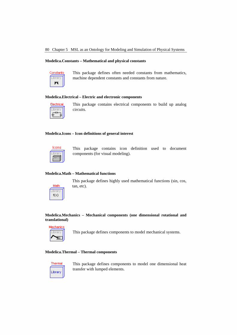
80 Chapter 5 MSL as an Ontology for Modeling and Simulation of Physical Systems
Modelica.Constants – Mathematical and physical constants
This package defines often needed constants from mathematics, machine dependent constants and constants from nature.
Modelica.Electrical – Electric and electronic components
This package contains electrical components to build up analog circuits.
Modelica.Icons – Icon definitions of general interest
This package contains icon definition used to document components (for visual modeling).
Modelica.Math – Mathematical functions
This package defines highly used mathematical functions (sin, cos, tan, etc).
Modelica.Mechanics – Mechanical components (one dimensional rotational and translational)
This package defines components to model mechanical systems.
Modelica.Thermal – Thermal components
This package defines components to model one dimensional heat transfer with lumped elements.

Modelica Standard Library (MSL) 81
Modelica.Siunits – SI-unit type definitions (according to ISO 31-1992)
This package provides predefined types such as Mass, Length, Time, etc, based on the international standards on units.
5.4.2 Discussion on the Modelica Standard Library
The features of the Modelica language and Modelica tools have made easy for designers to create models. The Modelica Standard Library provides a shared repository of components for reuse in different models. Tools like MathModelica (MathCore [69]) are using the Modelica Standard Library to help users visually pick and connect components into larger models as in Figure 5-1.
Figure 5-1. Visual construction of models using MathModelica.
From the left part of the Figure 5-1 the components of a MSL library can be dragged into the current model where they can be connected and further configured. Because the components are very generic and highly configurable they can be easily re-used in different models or different parts of the same model.
The library developers can impose certain weak restrictions on the use of the components to ensure that they cannot be misused. However, the Modelica
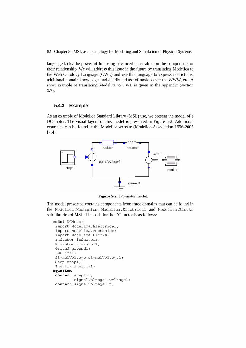
82 Chapter 5 MSL as an Ontology for Modeling and Simulation of Physical Systems
language lacks the power of imposing advanced constraints on the components or their relationship. We will address this issue in the future by translating Modelica to the Web Ontology Language (OWL) and use this language to express restrictions, additional domain knowledge, and distributed use of models over the WWW, etc. A short example of translating Modelica to OWL is given in the appendix (section 5.7).
5.4.3 Example
As an example of Modelica Standard Library (MSL) use, we present the model of a DC-motor. The visual layout of this model is presented in Figure 5-2. Additional examples can be found at the Modelica website (Modelica-Association 1996-2005 [75]).
Figure 5-2. DC-motor model.
The model presented contains components from three domains that can be found in the Modelica.Mechanics, Modelica.Electrical and Modelica.Blocks sub-libraries of MSL. The code for the DC-motor is as follows:
model DCMotor import Modelica.Electrical; import Modelica.Mechanics; import Modelica.Blocks; Inductor inductor1; Resistor resistor1; Ground ground1; EMF emf1; SignalVoltage signalVoltage1; Step step1; Inertia inertia1; equation connect(step1.y, signalVoltage1.voltage); connect(signalVoltage1.n,

Modelica Standard Library (MSL) 83
resistor1.p); connect(resistor1.n, inductor1.p); connect(signalVoltage1.p, ground1.p); connect(ground1.p, emf1.n); connect(inductor1.n, emf1.p); connect(emf1.rotFlange_b, inertia1.rotFlange_a); end DCMotor;
The connections between components are realized by the connect statement and can only be established between connectors of equivalent types. This ensures that only valid connections can be made between components.
A model definition can import several packages in order to use the classes defined in them. The packages can be extended through inheritance or specialized through redeclaration. The imports can be named (i.e. import
SI=Modelica.Siunits), qualified or unqualified (import everything). These features provide a detailed control over the imported definitions and help avoid name conflicts.
In this paper we focused more on the model design part and less on the simulation of the created models. For simulation the models are checked for correctness according to the Modelica static semantics, flattened and translated to highly efficient C code glued with numerical solvers. We simulate the DC-motor model and plot a few of its variables in Figure 5-3.
simulate(DCMotor,stopTime=25); plot({step1.y,inertia1.flange_a.tau})
0
-0.5
0.5
1.0
-1.0
1 5 10 15 20
Figure 5-3. DCMotorCircuit simulation with
plot of input signal voltage step and the flange angle.

84 Chapter 5 MSL as an Ontology for Modeling and Simulation of Physical Systems
5.5 Conclusions and Future Work
We have presented parts of the Modelica Standard Library (MSL) and showed how MSL is used when building models. We have also outlined the main similarities and differences between Modelica and other ontology languages (W3C [120], [122]) developed in the Semantic Web community.
As future work we would like to automatically construct an ontology translated from MSL into the Web Ontology Language (OWL). We can foresee that the structural part of the Modelica classes can be translated easily into OWL as we briefly show in the appendix (section 5.7). The non-trivial part would be to build the relationships between the translated concepts. Such relationships would require additional ontologies that provide concepts for system decomposition, physical processes, etc. These ontologies, combined with the Semantic Web technologies would add new functionality to Modelica tools like:
• Classifying new concepts (classes) and verifying models (i.e. that a model is coherent, etc)
• Imposing additional restriction over the models (i.e. an electric circuit must have a ground component, a car must have 4 wheels, etc)
• Expressing some of the Modelica static semantics directly in OWL (inheritance, subtyping, etc).
5.6 Acknowledgements
We would like to thank to all people in the Modelica community (Modelica-Association 1996-2005 [75]) who are actively involved in the development and maintenance of the Modelica Standard Library.
5.7 Appendix
In this section we show a simple example of how structural parts of Modelica could be translated into OWL. This kind of translation could be further augmented with additional constraints or information. Also, an OWL validator would be able to check such documents.
The following Modelica models and their translation into OWL are presented in the following:
class Body "Generic body" Real mass; String name; end Body;
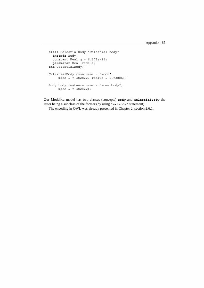
Appendix 85
class CelestialBody "Celestial body" extends Body; constant Real g = 6.672e-11; parameter Real radius; end CelestialBody; CelestialBody moon(name = "moon", mass = 7.382e22, radius = 1.738e6); Body body_instance(name = "some body", mass = 7.382e22);
Our Modelica model has two classes (concepts) Body and CelestialBody the latter being a subclass of the former (by using "extends" statement).
The encoding in OWL was already presented in Chapter 2, section 2.6.1.


Chapter 6 Debugging Natural Semantics Specifications
Adrian Pop, Peter Fritzson: Debugging Natural Semantics Specifications, submitted to the Sixth International Symposium on Automated and Analysis-Driven Debugging (AADEBUG 2005), March 2005.
6.1 Abstract
This paper presents the design, implementation and usage of a debugging framework for the Relational Meta-Language (RML) which is a language for writing executable Natural Semantics specifications. The language is successfully used at our department for writing large specifications for a range of languages like Java, Modelica, Pascal, MiniML etc. The RML system previously had no debugging facilities, which made it hard for programmers to debug their specifications. With this work we address these issues by providing a debugging framework for debugging high level Natural Semantics specifications in RML.
Categories and Subject Descriptors
D.2.5 [Testing and Debugging]. D.2.4 [Software/Program Verification]. D.3.4 [Programming Languages]:Processors—debuggers. D.3.2 [Programming Languages]: Language Classifications—applicative (functional) languages
General Terms: Debugging and Verification.
Keywords: Debugging, rule-based, logical functional languages, proof-trees.

88 Chapter 6 Debugging Natural Semantics Specifications
6.2 Introduction
No programming language environment can be considered mature if is not supported by a strong set of tools which include debugging and profiling. At our department we have developed a language called Relational Meta-Language (RML) (PELAB 1994-2005 [86], Pettersson 1995 [88], 1999 [90]) for writing Natural Semantics specifications.
The RML language is extensively used for teaching and writing large specifications for different languages like Java, Modelica, MiniML (Clément et al. 1986 [25]), Pascal, etc. Even if the RML language has a very short learning curve, the absence of debugging facilities previously created problems of understanding, debugging and verification of large specifications.
To overcome these issues a debugging framework for RML was designed and implemented. The debugger is based on abstract syntax tree instrumentation (program transformation) in the RML compiler and some runtime support. Type reconstruction is performed at runtime in order to present values of the user defined types. For inspecting complex variable values, an external data browser was implemented. Post mortem analysis is possible by recording parts of or the entire specification trace in an XML file, which can be queried using available XML tools (XML (W3C [113]), XQuery (W3C [117]), XPath and XSLT (W3C [116]), etc).
The paper is structured as follows: this section presents an introduction. The next section compares our work with existing research. Section 6.4 introduces Natural Semantics and the Relational Meta-Language (RML). The design and implementation of the debugger is the topic of section 6.5. The debugger functionality is presented using examples in section 6.6. The browser for variable values is presented in section 6.7. Section 6.8 describes shortly the post-mortem analyses one can describe on the recorded trace. In section 6.9 performance results of our debugger are presented. Conclusions and future work is the subject of section 6.10. Acknowledgements and references conclude the last two sections of the paper.
6.3 Related Work
As pointed out in (Liebermann 1997 [65]), the computer science community is constantly ignoring the debugging problem even tough the debugging phase of software development takes more than the overall development time. With our work we contribute to improving this state of affairs.
In lazy functional languages like Haskell the execution order is hard to understand. Partly for these reasons the Evaluation Dependence Tree (EDT) tree (Nilsson 1998 [79]) concept was proposed to help the understanding and debugging of the language. On the other hand, RML is a strict functional language where
Natural Semantics and the Relational Meta-Language (RML) 89
arguments are evaluated before the call and in this respect closer to Standard ML (Milner et al. 1997 [74]). Our work is related to the work done for Standard ML debugger (Tolmach and Appel 1995 [110], Tolmach 1992 [111]). We have not yet implemented time traveling, but this is one of our future work directions. General design ideas were inspired from (Pettersson 1998 [89]).
Using assertions and print statements for debugging was and unfortunately still is many programmers choice for debugging programs. Source code instrumentation (or program transformation) that changes the program code in order to facilitate debugging is an approach present approach in the literature (Fritzson et al. 1994 [35], Pope and Naish 2003 [98]).
Explanation of program execution in deductive systems like Deductive Databases (Mallet and Ducassé 1999 [67]) or Description Logic reasoners (McGuinness 1996 [71], McGuinness and Borgida 1995 [70], McGuinness and Silva 2003 [72]) has similarities with our RML debugger because they generate and analyze proof-trees (or derivation trees). RML is based on the style and visual layout of Natural Semantics and has a top-down left-right determinate search with local backtracking as proof procedure.
6.4 Natural Semantics and the Relational Meta-Language (RML)
Natural Semantics (Kahn [57]) is formalism for specifying many aspects of programming languages, e.g. type systems, dynamic semantics, translational semantics, static semantics, etc. Natural Semantics is an operational semantics derived from the Plotkin (Plotkin 1981 [91]) structural operational semantics combined with the sequent calculus for natural deduction.
The Relational Meta-Language (RML) (PELAB 1994-2005 [86], Pettersson 1995 [88], 1999 [90]), is a practical language for writing Natural Semantics Specifications. The RML language is compiled to highly efficient C code by the rml2c compiler. In this way, large parts of a compiler can be automatically generated from their Natural Semantics specifications.
From the features of the RML language we can mention: strong static typing, simple module system, type inference, pattern matching and recursion are used for control flow, types can be polymorphic.
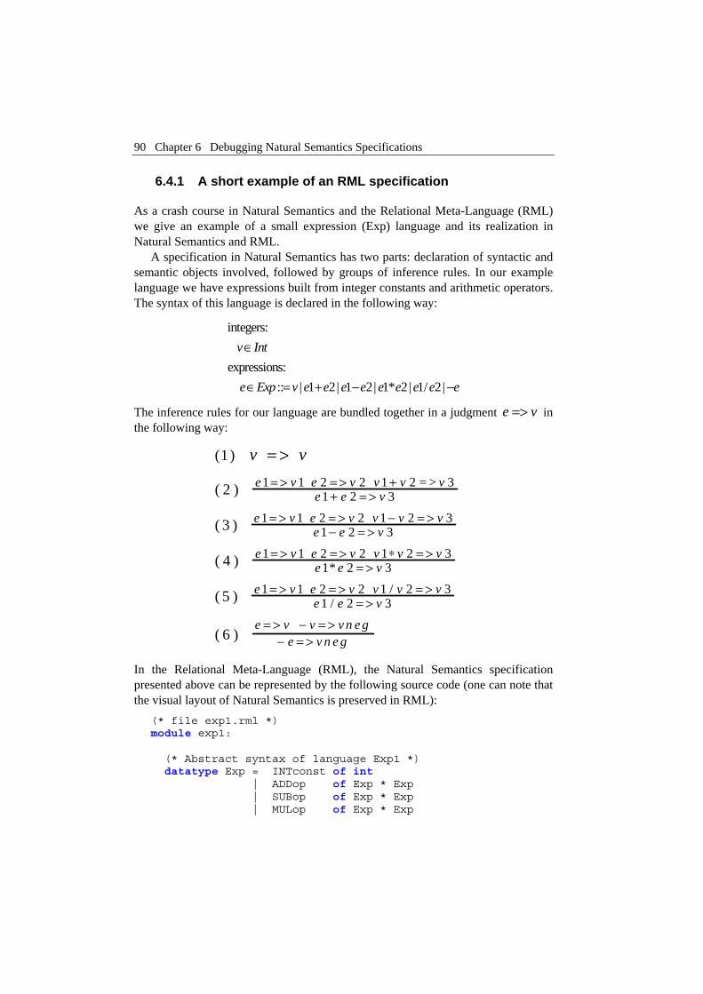
90 Chapter 6 Debugging Natural Semantics Specifications
v
6.4.1 A short example of an RML specification
As a crash course in Natural Semantics and the Relational Meta-Language (RML) we give an example of a small expression (Exp) language and its realization in Natural Semantics and RML.
A specification in Natural Semantics has two parts: declaration of syntactic and semantic objects involved, followed by groups of inference rules. In our example language we have expressions built from integer constants and arithmetic operators. The syntax of this language is declared in the following way:
integers: expressions: :: | 1 2| 1 2| 1* 2| 1/ 2|
v Int
e Exp v e e e e e e e e e
∈
∈ = + − −
The inference rules for our language are bundled together in a judgment in the following way:
e =>
1 1 2 2 1 2 = > 31 2 3
1 1 2 2 1 2 31 2 3
1 1 2 2 1 2 31* 2 3
1 1 2 2 1 / 2 31 / 2 3
(1 )
( 2 )
( 3 )
( 4 )
( 5 )
( 6 )
e v e v v v ve e v
e v e v v v ve e v
e v e v v v ve e v
e v e v v v ve e v
e v v v n e
v v= > = > +
+ = >
= > = > − = >− = >
= > = > ∗ = >= >
= > = > = >= >
= > − = >
= >
ge v n e g− = >
In the Relational Meta-Language (RML), the Natural Semantics specification presented above can be represented by the following source code (one can note that the visual layout of Natural Semantics is preserved in RML):
(* file exp1.rml *) module exp1: (* Abstract syntax of language Exp1 *) datatype Exp = INTconst of int | ADDop of Exp * Exp | SUBop of Exp * Exp | MULop of Exp * Exp

Natural Semantics and the Relational Meta-Language (RML) 91
| DIVop of Exp * Exp | NEGop of Exp relation eval: Exp => int end (* Evaluation semantics of Exp1 *) relation eval: Exp => int = (* Evaluation of an integer node *) axiom eval(INTconst(ival)) => ival (* Evaluation of an addition node ADDop * is v3, if v3 is the result of adding * the evaluated results of its children * e1 and e2 * Subtraction, multiplication, etc, * operators have very similar specs *) rule eval(e1) => v1 & eval(e2) => v2 & v1 + v2 => v3 ------------------------------------------------ eval( ADDop(e1, e2) ) => v3 rule eval(e1) => v1 & eval(e2) => v2 & v1 - v2 => v3 ------------------------------------------------ eval( SUBop(e1, e2) ) => v3 rule eval(e1) => v1 & eval(e2) => v2 & v1 * v2 => v3 ------------------------------------------------ eval( MULop(e1, e2) ) => v3
rule eval(e1) => v1 & eval(e2) => v2 & v1 / v2 => v3 ----------------------------------------------- eval( DIVop(e1, e2) ) => v3 rule eval(e) => v & -v => vneg -------------------------- eval( NEGop(e) ) => vneg end (* eval *)
The proof-theoretic interpretation is assigned to this specification. We interpret inference rules as recipes for constructing proofs.
6.4.1.1 Proof theoretic interpretation
We wish to prove that there is a value such that 1 2 holds for this specification. To prove this proposition, we need an inference rule that has a conclusion, which can be instantiated (pattern-matched) to the proposition. The only proposition (rule) that matches is the second one.
v v+ =>

92 Chapter 6 Debugging Natural Semantics Specifications
(2) 1 1 2 2 1 2 3
1 2=> => + =>
+ =>v v v v
vv
To prove further we need to apply the first proposition (here axiom) twice times and we reach the conclusion.
6.4.2 The rml2c compiler and the runtime system
The rml2c compiler is written in Standard ML ‘97 (Milner et al. 1997 [74]) using the Standard ML of New Jersey (SML/NJ) (SML/NJ-Fellowship 2004-2005 [108]) compiler. The compiler (Figure 6-1) uses several intermediate representations on which it makes extensive optimizations. The front-end generates ANSI-C code which is linked with the runtime system.
module Dump with “absyn.rml” relation dump: Absyn.Program => ()
Parse
RML AST Reordering Static Elaboration
Figure 6-1. The rml2c compiler phases.
FOL AST
Debugging Instrumentation
(Typecheck) RML AST to FOL
FOL to CPS via Pattern-Matching Compiler
CPS AST
CPS to Code
Code AST
Code to ANSI-C
ANSI-C Linking with the
RML runtime system
Executable

Debugger Design and Implementation 93
Immediately after parsing, the specification structure is saved in the RML Abstract Syntax Tree (AST). A reordering phase is performed in order to arrange the declarations in the correct order of dependencies. The static elaboration phase is performing type inference and it checks the program correctness. After the static elaboration phase the current RML AST representation is translated to FOL (a language similar to First Order Logic) representation. On this representation optimizations that improve determinism are applied and the result is translated to CPS (Continuation Passing Style) via a Pattern-Matching Compiler. Optimizations like constant and copy propagation and also inlining are applied to CPS. The CPS representation is translated to a low level imperative representation (Code) that has explicit memory management, data construction and control flow. In the last phase the Code is translated to ANSI-C. All these phases are depicted in Figure 6-1.
The RML system has two runtime systems: one for fast execution and one for profiling and some logging of the runtime internals.
6.5 Debugger Design and Implementation
The design of the debugger had the following requirements as starting points:
• Conventional debugger functionality (breakpoints, variable value inspections, call chain, stack trace, etc.)
• Inspection/printing of large values. • Type querying facilities for variables, relations, datatypes. • Special features for failure discovery (In RML, when a relation fails, the
entire specification can also fail. Because of this, is very important to have special functionality for discovering where and under what conditions such failure took place.)
• Modular design for easy integration with other tools and graphical user interfaces.
• Reuse of the existing rml2c compiler and runtime system.
These requirement specifications were driven by existing tool implementation (the rml2c compiler and the runtime system) and easy future extensions and integration. Also, extensive user knowledge and experience when writing RML specifications was used to derive the debugger requirements.
According to the requirements, the only changes of the rml2c compiler and runtime system to support debugging were:
• Addition of a new phase that instruments the RML AST with debugging nodes. This phase is triggered from a command line parameter.
• Small changes to the static elaboration phase to output a program database with names and types for all the language identifiers. This program database

94 Chapter 6 Debugging Natural Semantics Specifications
is used from external tools such as the RML Project Browser and the RML debugging runtime system to query for types of identifiers.
• Addition of a new runtime which has debugging functionality.
The new tools that were developed to aid the debugging task were the RML Data Browser, the Emacs Mode for RML debugging and the Post Mortem Analysis tool.
6.5.1 Overview
The RML integrated environment with debugging and the various interactions between the components are presented in Figure 6-2.
In the following we only describe the use of the toolbox with regards to debugging. The RML Project Browser is a navigator for RML specifications that ease the browsing of relations and datatypes.
Figure 6-2. Tool coupling within the RML integrated environment with debugging.
The rml2c compiler takes as input an RML specification. The specification is instrumented with debug nodes. Then, the normal compilation phases are applied until C code is generated. The generated C code is compiled and linked with the debugging runtime system. Also, the compiler dumps the program database at the end of static elaboration phase, after performing type inference.
rml2c compiler External Program Database
Linking with one of the
RML runtimes
ANSI-C
RML Project Browser
Emacs Mode for
RML Debugging
RML Data Value Browser
Execution Recording in
XML
Executable with
Debugging
module Dump with “absyn.rml” relation dump: Absyn.Program => () ...
Post Mortem Analysis Tool
Debugger Design and Implementation 95
When started, the executable reads in the program database and waits for user commands. This is a good time to set breakpoints using commands or helpers from Emacs Mode for RML Debugging. Then the execution can be resumed. At breakpoints one can print variable values directly in the standard output or they can be sent to the RML Data Value Browser for thorough inspection.
User commands are available in the debugger for recording of the execution in an XML trace. The XML trace can be analyzed post-mortem using XML tools. In this way, when a certain relation fails and generates the failure of the entire specification, one can understand when and why that happens by a post-mortem analysis of the execution trace.
6.5.2 Design Decisions
This section discusses the design decisions that were taken in the design process of our debugging tools.
6.5.2.1 Debugging Instrumentation
The RML compiler has several intermediate representations on which aggressive optimizations are applied. Because of this, debugging approaches that keep a mapping between intermediate representations and store reverse transformations of optimizations were out of the question. The best available approach was to apply debugging instrumentation at the RML AST level.
6.5.2.2 External program database
In order to present variable values using user-defined data structure one has to do type reconstruction at runtime. There were two possibilities of keeping a program database with the defined relations, variables, types and datatypes:
• Storing the needed information obtained after type inference in SML data structures and generating C code with this information in the Code to C phase of the compilation.
• Exporting the needed information to external files which can be read later by the runtime system.
We choose the second alternative because this kind of information is also useful in powerful RML IDE (which includes the RML Project Browser) that provides code assist (IntelliSense), displaying of types when hovering over variables and relations, pattern writing wizards, project browser, etc. We have already started to develop such IDE for RML and we will report on this work in a future article.

96 Chapter 6 Debugging Natural Semantics Specifications
6.5.2.3 External Data Value Browser
After implementing the printing of variable values to standard output it soon became apparent that for large values such displaying is unreadable. As an alternative we have implemented a very simple but practical value browser prototype. One nice feature: the browser provides immediate information about where tin the specification code each part of the data structure was defined. Future work on this prototype could provide new functionality i.e. for searching, and analyses of the variables.
6.5.2.4 Why not an interpreter?
Interpreters are good when one wants hands on development with fast feedback. However, they are quite slow, because optimizations cannot be applied if one wants to give a clear feedback to the user. Also, we already had the compiler. As a future project we will consider implementing an interpreter.
6.5.3 Instrumentation function
In this section we define the transformations that are performed by the instrumentation function over the RML AST. The instrumentation function is simple but very effective. In order to define this function we need to explain in more detail some parts of the RML language. The detailed RML specification can be found in (PELAB 1994-2005 [86], Pettersson 1995 [88], 1999 [90]).
RML modules have two parts: the interface specification (which defines the signatures that are to be exported from the current module) and the actual declaration of relations, private module types, datatypes, relations and global values. Clauses (rules and axioms) can be grouped together in relations. Rules have three parts: the matching pattern, premises, and results. Axioms are just rules without premises.
Premises (also called goals) can be of the following types:
Bindings let pat = exp
Unification var = exp Relation calls longIdentifier(expseq) => patseq
Negation not premise
Sequence premise & premise
Table 6-1. RML premise types. These constructs are swept for variables to be registered with the debugging runtime system.

Debugger Design and Implementation 97
Clauses (rules and axioms) have the following form: rule <premise> ------------------ var(pat) => result axiom var(pat) => result
Premises can be optional in rules or a sequence of premises. Axioms are just rules without premises.
The debugging instrumentation Instr function transforms only premises in the following way:
Instr(premise) = RML.register_in(parameters) & RML.debug(...) & premise & RML.register_out(results)
For a sequence of premises the result variables from last executed premise, together with the parameter of the next premise, are registered with the debugging framework. Then the debugger function RML.debug(...) checks for breakpoints, user commands or single-stepping. The debug function has as parameters the source filename, the line/column number of the premise, and the premise textual representation.
As one can see for each premise a sequence of three premises are generated. We could have got the live variables for a premise from the runtime system, but we use instead call premises that register these in/out variables. We used this approach because in the runtime system some variables are not present due to optimizations and also a mapping should have been kept that map existing source code variable names to positional parameters of relations. The parameters of variable registration functions are built by sweeping the premises for variables that appear in expressions or patterns.
6.5.4 Type reconstruction in the runtime system
The debugging runtime system is loading the program database files at startup and stores them in some internal structures. When the program is executed in the RML.debug(...) function the filename and the line/column position of the current execution point are known. With this knowledge and the name of the variable to be printed the program database information is searched for a rule that frames this point and contains the variable. The variable type is then retrieved.
The variable values are stored in the RML runtime heap as tagged pointers or immediate values. Immediate values are only integers. All other values are boxed and tagged. The tags contain information about the structure and elements of the values.

98 Chapter 6 Debugging Natural Semantics Specifications
Starting from the variable type and the variable pointer which was registered using the register_in/register_out functions the variable value is traversed. At the same time the variable type is unfolded and the new type components are mapped to the current variable components.
6.5.5 Debugger implementation
The implementation of the debugger follows the design closely.
6.5.5.1 The rml2c compiler addition
In the rml2c compiler we implemented the instrumentation phase as a separate Standard ML module that has as input the RML AST and as output the transformed RML AST with the debug nodes added. This additional phase is triggered by a command line parameter to the rml2c compiler. Also, the instrumentation can be applied selectively module or relation wise in order to instrument only the problematic parts of the specification and achieve a faster debugging execution.
In the static elaboration phase, after type inference is performed we saved the type information (that was normally discarded) in an identifier dictionary based on balanced search trees. At the end of the phase we write this information to the program database file in a flat format composed of: the identifier type, the file where it appears, the identifier, the line/column number and its type. A small portion of the program database file for our exp1.rml example specification is presented in the appendix (section 6.12).
6.5.5.2 The debugging runtime system
All the low-level runtime debugger functionality is implemented in C. The user commands are read by a command parser and the program database is read using another parser. The parsers are implemented using Flex (Lex) (GNU 2005 [46]) and Bison (Yacc) (GNU 2005 [47]) and the readline library (GNU 2005 [48]) (for history, command input handling, etc).
The program database is read and stored internally in the runtime as a list. An ordering phase is then performed to have the information indexed over module name (filename) and line number.
The RML.debug(...) relation is implemented also in C and uses the RML foreign function interface. The relation checks if a breakpoint was reached and in that case stops the execution, prints the next premise to be executed and waits for user commands. The relations RML.register_in("var_name", var, ...) and RML.register_out("var_name", var, ...) save the live variable information in internal arrays as (variable name, pointer to variable value) pairs.
Debugger Functionality 99
Only registered variables can be printed or sent to the external variable value browser.
The printing or sending of the variable values is realized by recursive functions that traverse both the value structure and the value type at the same time. The type of certain variable is retrieved from the program database information by matching the file, the name of the variable and the positional frame of the rule. These traversing and displaying functions take into consideration the printing depth, which is a debugger setting and can be changed using commands. Sockets are used when variable values are sent to the external browser.
6.5.5.3 The data value browser
The browser is implemented in Java to have the same high portability as the RML system. The browser waits to read variable value information from sockets and displays them in a tree structure constructed by using the traversal depth.
Syntax highlighting of RML files is performed by the browser, using a similar Emacs RML Mode style to keep the users on familiar grounds.
6.5.5.4 The Post-Mortem analysis tool
In this tool, at the moment we have only implemented a Failure analyzer that helps users understand where and why their specification failed. The analyzer is implemented in Java and replays the specification execution by navigation in the saved XML trace. One can stop, go back and forward in time, display variable values, etc. In general users start from the end of the execution and go back to where their specification failed.
The trace files can be quite large, in the order of several hundred megabytes. To overcome this problem we gave the users the possibility to configure the tracer using a small specification file that contains:
• Module, relation and/or rule to be traced. • Selection of variable names to include only their value in the trace.
This file is read by the tracer function and all the information is filtered accordingly. We plan to implement more analyses and automated debugging in the future.
Also, tuning of the specification data structures and its operational properties could be suggested by trace analysis.
6.6 Debugger Functionality
The Emacs RML debug mode is implemented as a specialization of the Grand Unified Debugger (GUD) interface (gud-mode) from Emacs (GNU 2005 [45]).

100 Chapter 6 Debugging Natural Semantics Specifications
Because the RML debug mode is based on the GUD interface, some of the commands have the same familiar key bindings.
The actual commands sent to the debugger are also presented together with GUD commands preceded by the RML debugger prompt: rmldb@>.
If the debugger commands have several alternatives these are presented using the notation:alt1|alt2. The optional command components are presented using notation: [optional].
In the Emacs interface: M-x stands for holding down the Meta key (mapped to Alt in general) and pressing the key after the dash, here x, C-x stands for holding down the Control (Ctrl) key and pressing x, <RET> is equivalent with pressing the Enter key and <SPC> with pressing Space key.
The next subsections present a debugging session on the RML example specification presented in subsection 6.4.1.
6.6.1 Starting the RML Debugging Subprocess
The command for starting the RML debugger under Emacs: M-x rmldb <RET> executable <RET>
6.6.2 Setting/Deleting Breakpoints
A part of a session using this type of commands is shown in Figure 6-3. The presentation of the commands follows.
To set a breakpoint on the line the cursor (point) is at: C-x <SPC> rmldb@> break on file:lineno|string <RET>
To delete a breakpoint placed on the current source code line (gud-remove): C-c C-d C-x C-a C-d rmldb@> break off file:lineno|string <RET>
Instead of writing break one can use alternatives br|break| breakpoint. Alternatively one can delete/display all breakpoints using:
rmldb@> cl|clear <RET> rmldb@> sh|show <RET>

Debugger Functionality 101
Figure 6-3. Using breakpoints.
6.6.3 Stepping and Running
To perform one step (gud-step) in the RML code: C-c C-s C-x C-a C-s rmldb@> st|step <RET> rmldb@> <RET>

102 Chapter 6 Debugging Natural Semantics Specifications
To continue after a step or a breakpoint (gud-cont): C-c C-r C-x C-a C-r rmldb@> ru|run <RET>
Examples of using these commands are presented in Figure 6-4.
Figure 6-4. Stepping and running.
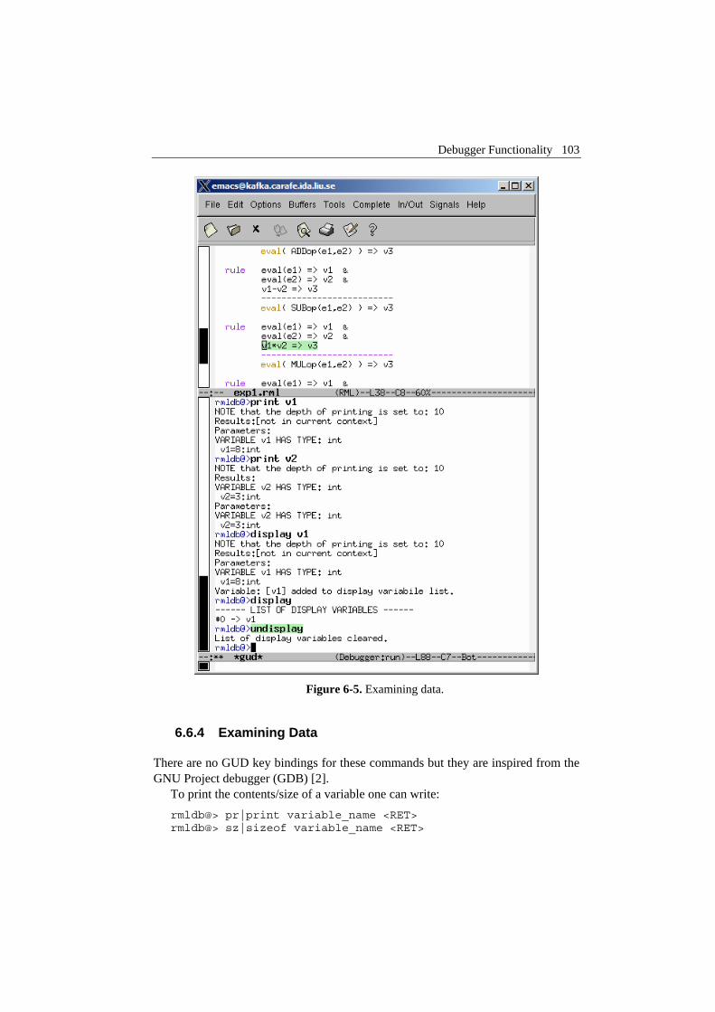
Debugger Functionality 103
Figure 6-5. Examining data.
6.6.4 Examining Data
There are no GUD key bindings for these commands but they are inspired from the GNU Project debugger (GDB) [2].
To print the contents/size of a variable one can write: rmldb@> pr|print variable_name <RET> rmldb@> sz|sizeof variable_name <RET>

104 Chapter 6 Debugging Natural Semantics Specifications
at the debugger prompt. The size is displayed in bytes. Variable values to be printed can be of a complex type and very large. One can
restrict the depth of printing using: rmldb@> [set] de|depth integer <RET>
Moreover, we have implemented an external data value browser written in Java called RMLDataViewer to browse the contents of such a large variable. To send the contents of a variable to the external viewer for inspection one can use the command:
rmldb@> bw|browse|gr|graph var_name <RET>
at the debugger prompt. The debugger will try to connect to the RMLDataViewer and send the contents of the variable. The external data browser has to be started a priori. If the debugger cannot connect to the external viewer within a specified timeout a warning message will be displayed. More about the external RMLDataViewer tool can be found in section 6.7.
If the variable which one tries to print does not exist in the current scope, a notifying warning message will be displayed.
Automatic printing of variables at every step or breakpoint can be specified by adding a variable to a display list:
rmldb@> di|display variable_name <RET>
Removing a display variable from the display list: rmldb@> un|undisplay variable_name <RET>
To print the entire display list or to remove all variables from it: rmldb@> di|display <RET> rmldb@> un|undisplay <RET>
Printing the current live variables (variables available in the scope): rmldb@> li|live|livevars <RET>
Instructing the debugger to print or to disable the print of the live variable names at each step/breakpoint:
rmldb@> [set] li|live|livevars on|off]<RET>
Figure 6-5 shows examples of some of these commands within a debugging session.

Debugger Functionality 105
6.6.5 Additional commands
Additional commands provide functionality for displaying the call chain, the stack contents, the runtime status, etc. A session using some of these commands is presented in Figure 6-6.
Figure 6-6. Additional debugging commands.
The stack trace can be displayed using:

106 Chapter 6 Debugging Natural Semantics Specifications
rmldb@> bt|backtrace <RET>
Because the contents of the stack can be quite large, one can print a filtered view of it:
rmldb@> fbt|fbacktrace filter_string <RET>
Also, one can restrict the numbers of entries the debugger is storing using: rmldb@> maxbt|maxbacktrace integer <RET>
Also, the call chain is available in the debugger. Similar commands as for the backtrace are available for call chain trace.
For displaying the status of the RML runtime: rmldb@> sts|stat|status <RET>
The status of the RML runtime comprises information regarding the garbage collector, allocated memory, stack usage, etc.
The current debugging settings can be displayed using: rmldb@> stg|settings <RET>
The settings printed are, i.e.: the maximum remembered stack entries, the depth of variable printing, the current breakpoints, the live variables, the list of the display variables and the status of the runtime system.
One can invoke the debugging help or exit the debugger by issuing: rmldb@> he|help <RET> rmldb@> qu|quit|ex|exit|by|bye <RET>
6.7 The Data Value Browser
The RMLDataViewer is a browser for variable values and a new addition to our debugging tools for RML. The need for such a tool became apparent when debugging specifications that use very large data structures (for example abstract syntax tree definitions for a certain language).
From the executable, at the debugging prompt one can invoke a browse command which sends the queried variable value for displaying in the external browser. The variable values can be limited in depth using set depth command. In this way only needed parts of the variable value are sent.
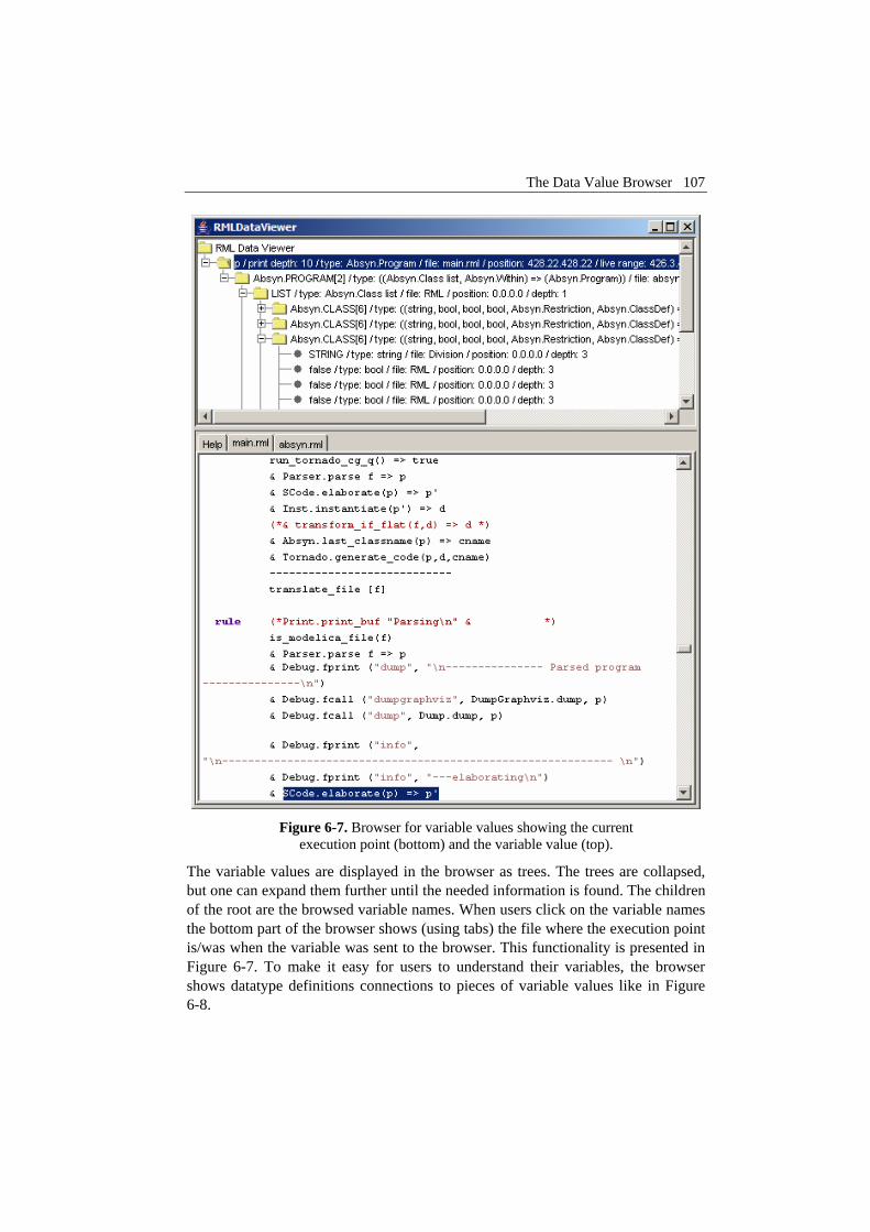
The Data Value Browser 107
Figure 6-7. Browser for variable values showing the current
execution point (bottom) and the variable value (top).
The variable values are displayed in the browser as trees. The trees are collapsed, but one can expand them further until the needed information is found. The children of the root are the browsed variable names. When users click on the variable names the bottom part of the browser shows (using tabs) the file where the execution point is/was when the variable was sent to the browser. This functionality is presented in Figure 6-7. To make it easy for users to understand their variables, the browser shows datatype definitions connections to pieces of variable values like in Figure 6-8.

108 Chapter 6 Debugging Natural Semantics Specifications
Figure 6-8. When datatype constructors are selected, the bottom part presents their source code definitions for easy understanding of the displayed values.
The screens were captured while debugging the OpenModelica (Fritzson et al. 2002 [37], PELAB 2002-2005 [87]) compiler specification and the variable value consists of the abstract syntax tree of the Modelica (Modelica-Association 1996-2005 [75]) language.
6.8 The Post-Mortem Analysis Tool
As pointed out in the debugger design and implementation, one can record parts of or the entire execution trace of the specification in an XML file. The trace can then be analyzed by tools that point out specific issues.

Performance Evaluation 109
In our post-mortem analysis environment we have developed a tool called Failure analyzer. The Failure analyzer is a replay debugger which is able to walk back and forth in time, display variable values, execution points, etc. When their specification fails the users can run this analyzer over the recorded trace, start from the end of the execution and go back and investigate where the execution has failed and why. This tool was very important for our users, because, for large specifications, is not trivial to understand where and why your specification failed.
The Failure analyzer tool is similar to the data value browser, but has buttons for navigation in time, setting/deleting breakpoints and displaying values.
6.9 Performance Evaluation
In this section we make performance evaluation of our debugging strategy on three real-world semantic specifications that define compilers for extended Pascal (petrol), a small functional language (MiniML (Clément et al. 1986 [25])) and a large Modelica compiler (OpenModelica). The first two specifications are part of the examples bundled with the RML system (PELAB 1994-2005 [86], Pettersson 1995 [88], 1999 [90]) and the Modelica compiler was implemented in the OpenModelica project (Fritzson et al. 2002 [37], PELAB 2002-2005 [87]) and is also available for download at the project address. The semantic specifications were compiled to two versions of executables one in release mode and one in debugging mode. The compilers were then used to compile programs and the compilation performance was measured.
We have tested the performance of our debugger on an Intel Pentium Mobile at 1.5Ghz with 480 MB of RAM memory. We compared code growth, execution time, stack consumption, and number of relation calls.
If we consider that a premise (one call) is executed in O(1) then the complexity of the call combined with the instrumentation will be O(number of variables from the premise)+O(premise)+O(call to the step function) which is a complexity in the order of the numbers of variables present in the specification.
6.9.1 Code growth
Table 6-2 below shows the additional number of lines of code added during code instrumentation. The code growth is between 1.3 and 1.7 which is quite limited. We can see that for very large specifications like the OpenModelica compiler the code grows less than for smaller specifications. The code growth was measured on the files obtained from the abstract syntax tree unparsing before and after the instrumentation. The comments were ignored.

110 Chapter 6 Debugging Natural Semantics Specifications
test/mode (debug/normal)
normal debug
petrol (1.63) 2513 4083 miniml (1.57) 1112 1747
OpenModelica (1.36) 57186 77961
Table 6-2. Size (#lines) without and with instrumentation.
6.9.2 The execution time
The execution time was also measured and the results are presented below.
test/mode (debug/normal)
normal (seconds)
debug (seconds)
petrol (24.63) 0.12 2.96 miniml (11.19) 6.14 68.71
OpenModelica (20.55) 0.20 4.11
Table 6-3. Running time without and with debugging.
Table 6-3 presents a performance evaluation of our debugger. As one can notice, the programs compiled in debug mode are between 10 and 25 times slower than the programs compiled without debugging. We find this very acceptable, as this is the first prototype and we can get more speedup from various optimizations we can apply to the debugging code. For the user, the delay times due to the added debugging code are practical. We can note also that very large specifications can be debugged without too much penalty.
6.9.3 Stack consumption
We have investigated the stack consumption needed during debugging versus the normal memory consumption. The results are summarized in Table 6-4.
test/mode
(debug/normal) normal (words)
debug (words)
petrol (1.19) 249 297 miniml (1.01) 8966 9126
OpenModelica (1.06) 1447 1543
Table 6-4. Used stack without and with debugging.
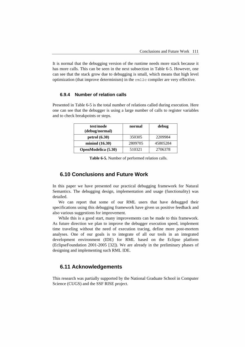
Conclusions and Future Work 111
It is normal that the debugging version of the runtime needs more stack because it has more calls. This can be seen in the next subsection in Table 6-5. However, one can see that the stack grow due to debugging is small, which means that high level optimization (that improve determinism) in the rml2c compiler are very effective.
6.9.4 Number of relation calls
Presented in Table 6-5 is the total number of relations called during execution. Here one can see that the debugger is using a large number of calls to register variables and to check breakpoints or steps.
test/mode
(debug/normal) normal debug
petrol (6.30) 350305 2209984 miniml (16.30) 2809705 45805284
OpenModelica (5.30) 510321 2706378
Table 6-5. Number of performed relation calls.
6.10 Conclusions and Future Work
In this paper we have presented our practical debugging framework for Natural Semantics. The debugging design, implementation and usage (functionality) was detailed.
We can report that some of our RML users that have debugged their specifications using this debugging framework have given us positive feedback and also various suggestions for improvement.
While this is a good start, many improvements can be made to this framework. As future direction we plan to improve the debugger execution speed, implement time traveling without the need of execution tracing, define more post-mortem analyses. One of our goals is to integrate of all our tools in an integrated development environment (IDE) for RML based on the Eclipse platform (EclipseFoundation 2001-2005 [32]). We are already in the preliminary phases of designing and implementing such RML IDE.
6.11 Acknowledgements
This research was partially supported by the National Graduate School in Computer Science (CUGS) and the SSF RISE project.

112 Chapter 6 Debugging Natural Semantics Specifications
6.12 Appendix
An excerpt from a program database file (saved as exp1.rdb) for our exp1.rml specification is given below. The first character defines the kind of the identifier: variable, type, datatype constructor or relation.
v: exp1.rml:16.24.16.27|range[16.3.16.38]|eval[ival:int] v: exp1.rml:28.25.28.26|range[24.3.28.35]|eval[e2:exp1.Exp] ... t: exp1.rml:3.12.3.14|exp1.Exp c: exp1.rml:6.21.6.25|exp1.MULop:(exp1.Exp,exp1.Exp) => exp1.Exp c: exp1.rml:7.21.7.25|exp1.DIVop:(exp1.Exp,exp1.Exp) => exp1.Exp c: exp1.rml:4.21.4.25|exp1.ADDop:(exp1.Exp,exp1.Exp) => exp1.Exp c: exp1.rml:3.21.3.28|exp1.INTconst:int => exp1.Exp c: exp1.rml:5.21.5.25|exp1.SUBop:(exp1.Exp,exp1.Exp) => exp1.Exp c: exp1.rml:8.21.8.25|exp1.NEGop:exp1.Exp => exp1.Exp r: exp1.rml:14.10.14.13|exp1.eval:exp1.Exp => int

Chapter 7 Related research contributions
7.1 Introduction
In this chapter we give short summaries of additional publications that complete (or bring more detail level) this thesis in the proposed research goal.
7.2 A Functionality Coverage Analysis of Industrially Used Ontology Languages
Olof Johansson, Adrian Pop, Peter Fritzson: A Functionality Coverage Analysis of Industrially Used Ontology Languages, In Proceedings of the Model Driven Architecture: Foundations and Applications (MDAFA2004), June 10-11, 2004, Linköping, Sweden.
In this article we compare three industrially used ontologies at the functionality level. Ontology development for engineering applications and domains is a time consuming negotiation and development process that takes years to complete, involving many domain experts and tool vendors that must agree. Once agreement is reached, an ontology serves as a common language that allows engineers and machines to share data and knowledge. The long term goal with this work is to share and reuse engineering ontologies amongst different programming languages and tools, and thus facilitate engineering system integration and automated sharing of huge amounts of engineering knowledge and product data.
The paper presents and compares ontology functionality using UML diagrams for the software design language UML 1.5, the mathematical modeling language Modelica 2.1, and e-business datadictionary RosettanNet technical dictionary 3.2. The conclusion is that static, structural ontologies and product data can be shared

114 Chapter 7 Related research contributions
amongst these languages using fully automated processes. However UML TaggedValues and Modelica Annotations or CommentStrings must be used in a standardized way for full roundtrips.
7.3 Deriving a Component Model from a Language Specification: An Example Using Natural Semantics
Ilie Savga, Adrian Pop, Peter Fritzson: Deriving a Component Model from a Language Specification:An Example Using Natural Semantics, Technical Report, 2004, http://www.ida.liu.se/~adrpo/reports.
Development of a component model for a given language is tedious, time-consuming, and error-prone. Moreover, many tasks of this process have to be repeated when modeling sets of related languages. In this paper, we propose to use the meta-modeling approach and for a given language to derive an invasive component model as its derived meta-model. The derivation of a component model then becomes a horizontal extension of the corresponding language meta-model. We argue that, in principle, any language construct can be made generic by a mapping to a generic element of its component model. Moreover, for extensible language constructs additional mappings can be provided to support extensible component constructs. Using this approach, a generic and extensible component model can be derived from a given language and used both for generic and view-based programming.
The presented approach provides significant automation support in the development of component models for arbitrary languages.
As an example, we show the derivation of a component model using a Natural Semantics specification for a given language. The specification is defined using the Relational Meta-Language (RML), which is an executable implementation of Natural Semantics.
7.4 A Portable Debugger for Algorithmic Modelica Code
Adrian Pop, Peter Fritzson: A Portable Debugger for Algorithmic Modelica Code, In Proceedings of the 4th International Modelica Conference (Modelica2005), March 7-9 , 2005, Hamburg-Harburg, Germany.
In this paper we present the first comprehensive debugger for the algorithmic subset of the Modelica language, which augments previous work in our group on

115
declarative static and dynamic debugging of equations in Modelica. This replaces debugging of algorithmic code using primitive means such as print statements or asserts which is complex, time-consuming, and error- prone.
The debugger is portable since it is based on transparent source code instrumentation techniques that are independent of the implementation platform.
The usual debugging functionality found in debuggers for procedural or traditional object-oriented languages is supported: setting and removing breakpoints, single-stepping, inspecting variables, back-trace of stack contents, tracing, etc.
7.5 ModelicaDB – A Tool for Searching, Analyzing, Crossreferencing and Checking of Modelica Libraries
Olof Johansson, Adrian Pop, Peter Fritzson: ModelicaDB - A Tool for Searching, Analyzing, Crossreferencing and Checking of Modelica Libraries, In Proceedings of the 4th International Modelica Conference (Modelica2005), March 7-9, 2005, Hamburg-Harburg, Germany.
This paper presents ModelicaDB, a tool that provides several kinds of queries on repositories of Modelica models.
The Modelica language has a growing user community that produce a large and increasing code base of models. However, the reuse of models within the Modelica community can be greatly hampered in the future if there are no tools to address a number of management issues (i.e. scalable searching, analyzing, crossreferencing, checking, etc) of such a large repository of models.
We try to address these issues by providing the Modelica community with a ModelicaDB database for storing models and services for querying this database to perform a wide range of model engineering tasks in a scalable fashion.
In the long-term, this work also aims at providing integration between Modelica tools and advanced product development processes that rely on database technology.
7.6 Towards Comprehensive Meta-Modeling and Meta-Programming Capabilities in Modelica
Peter Fritzson, Adrian Pop, Peter Aronsson: Towards Comprehensive Meta-Modeling and Meta-Programming Capabilities in Modelica, In Proceedings of the

116 Chapter 7 Related research contributions
4th International Modelica Conference (Modelica2005), March 7-9, 2005, Hamburg-Harburg, Germany.
The need for integrating system modeling with tool capabilities is becoming increasingly pronounced. For example, a set of simulation experiments may give rise to new data that are used to systematically construct a series of new models, e.g. for further simulation and design optimization. Using models to construct other models is called meta-modeling or meta-programming.
In this paper we present extensions to the Modelica language for comprehensive meta-programming, involving transformations of abstract syntax tree representations of models and programs. The extensions have been implemented and used in several applications, and are currently being integrated into the OpenModelica environment.
Bibliography
[1] Alfred V. Aho, Ravi Sethi, and Jeffrey D. Ullman, Compilers: Principles, Techniques, and Tools. 1986, Reading, MA, Addison-Wesley.
[2] Altova, XmlSpy System, Last Accessed: 2005, Altova, www: http://www.xmlspy.com/.
[3] Mogens Myrup Andreasen, Machine Design Methods Based on a Systematic Approach (Syntesemetoder på systemgrundlag). 1980, Lund Technical University, Lund, Sweden.
[4] Andrew W. Appel, Modern Compiler Implementation in Standard ML. 1997, New York, Cambridge, Cambridge University Press.
[5] Andrew W. Appel, Modern Compiler Implementation in Java 2nd Edition. 2002, Princeton University, New Jersey, Cambridge University Press.
[6] Peter Aronsson, Peter Fritzson, Levon Saldamli, Peter Bunus, and Kaj Nyström. Meta Programming and Function Overloading in OpenModelica. ed. Peter Fritzson, Proceedings of 3rd International Modelica Conference, November 3-4, 2003. Linköping, Modelica Association, p.: 431-440, www: http://www.modelica.org/events/Conference2003/
[7] Uwe Aßmann, Thomas Genßler, and Holger Bär. Meta-programming Grey-box Connectors. ed. R. Mitchell, Proceedings of International Conference on Object-Oriented Languages and Systems (TOOLS Europe), June, 2000. Piscataway, NJ, IEEE Press
[8] Uwe Aßmann, Invasive Software Composition. 2003, Springer-Verlag.
[9] Uwe Aßmann and Andreas Ludwig, COMPOST (The Software COMPOsition SysTem), Last Accessed: 2005, 1998-2003 Karlsruhe University, IPD Prof. Goos,1998-2003 Andreas Ludwig, 2001-2003 Uwe Aßmann,2001-2003

118
Linköpings Universitet, IDA, PELAB, RISE, www: http://www.the-compost-system.org/.
[10] Isabelle Attali, Carine Courbis, Pascal Degenne, Alexandre Fau, Didier Parigot, and Claude Pasquier. SmartTools: A Generator of Interactive Environments Tools. ed. Reinhard Wilhelm, Proceedings of International Conference on Compiler Construction (CC2001), April, 2001. Genova, Italy, www: http://www-sop.inria.fr/smartool/
[11] Isabelle Attali, Carine Courbis, Pascal Degenne, Alexandre Fau, Joël Fillon, Didier Parigot, Claude Pasquier, and Claudio Sacerdoti Coen. SmartTools: a development environment generator based on XML technologies, Proceedings of The XML Technologies and Software Engineering (ICSE'2001), 2001. Toronto, Canada, ICSE workshop proceedings, www: http://www-sop.inria.fr/smartool/
[12] Franz Baader, Diego Calvanese, Deborah McGuinness, Daniele Nardi, and Peter Patel-Schneider, Description Logics Handbook. 2003, New York, NY, Cambridge University Press.
[13] Greg Badros. JavaML: A Markup Language for Java Source Code, Proceedings of Proceedings of The 9th International World Wide Web Conference, May 15-19, 2000. Amsterdam, Nederlands
[14] Daniela Berardi, Diego Calvanese, and Giuseppe De Giacomo. Reasoning on UML Class Diagrams using Description Logics Based Systems, Proceedings of KI'2001 Workshop on Applications of Description Logics, 2001, CEUR Electronic Workshop Proceedings, www: http://ceur-ws.org/Vol-44/
[15] Tim Berners-Lee, Semantic Web, Last Accessed: 2005, www: http://www.w3.org/2000/Talks/1206-xml2k-tbl/.
[16] Tim Berners-Lee, James Hendler, and Ora Lassila, The Semantic Web, in Scientific American. 2001.
[17] Johansson Björn, Jonas Larsson, Magnus Sethson, and Petter Krus. An XML-Based Model Representation for model management, transformation and exchange, Proceedings of ASME International Mechanical Engineering Congress, November 17-20, 2002. New Orleans, USA
[18] Alex Borgida, From Type Systems to Knowledge Representation: Natural Semantics Specifications for Description Logics. International Journal of Intelligent and Cooperative Information Systems, 1992, p.: 93-126.
[19] Patrik Borras, Dominique Clement, Thierry Despeyroux, Janet Incerpi, Gilles Kahn, Bernard Lang, and Valérie Pascual. CENTAUR: The System. ed. P. Henderson, Proceedings of ACM SIGSOFT/SIGPLAN Software Engineering

119
Symposium on Practical Software Development Environments, February, 1988, vol. 24 of SIGPLAN, p.: 14-24
[20] Pim Borst, Hans Akkermans, and Jan Top, Engineering ontologies. International Journal of Human-Computer Studies, 1997. vol: 46, p.: 365-406.
[21] R.H. Bracewell and D.A.Bradley. Schemebuilder, A Design Aid for Conceptual Stages of Product Design, Proceedings of International Conference on Engineering Design, IECD'93, 1993. The Hague
[22] Gilad Bracha and W. Cook. Mixin-based inheritance, Proceedings of OOPSLA/ECOOP'90, October, 1990, ACM SIGPLAN Notices, p.: 303-311
[23] Peter Bunus, Debugging and Structural Analysis of Declarative Equation-Based Languages, Department of Computer and Information Science. 2002, Linköping University, Linköping, Licentiate Thesis.
[24] Peter Bunus, Debugging Techniques for Equation-Based Languages, Department of Computer and Information Science. 2004, Linköping University, Linköping, PhD Thesis.
[25] Dominique Clément, Joëlle Despeyroux, Thierry Despeyroux, and Gilles Kahn. A Simple Applicative Language: Mini-ML, Proceedings of the ACM Conference on Lisp and Functional Programming, August, 1986. also available as research report RR-529, INRIA, Sophia-Antipolis, May 1986.
[26] Dominique Clément, Jöelle Despeyroux, Thierry Despeyroux, Laurent Hascoet, and Gilles Kahn. Natural Semantics on the Computer. ed. K. Fuchi and M. Nivat, Proceedings of France-Japan AI and CS Symposium, ICOT, 1986. Japan, p.: 49-89, www: http://www.inria.fr/rrrt/rr-0416.html
[27] DescriptionLogicsWebsite, Description Logics, Last Accessed: 2005, maintained by Carsten Lutz, www: http://dl.kr.org/.
[28] Thierry Despeyroux. Executable Specification of Static Semantics. ed. Gilles Kahn, Proceedings of Semantics of Data Types, 1984. Berlin, Germany, Springer-Verlag, Lecture Notes in Computer Science, vol. 173, p.: 215-233
[29] Thierry Despeyroux, TYPOL: A Formalism to Implement Natural Semantics, INRIA, Sofia-Antipolis, Report: RR 94, 1988, www: http://www.inria.fr/rrrt/rt-0094.html.
[30] Dynasim, Dymola, Last Accessed: 2005, www: http://www.dynasim.se/.
[31] EasyComp, The EasyComp EU project website, Last Accessed: 2004, www: http://www.easycomp.org/.
120
[32] EclipseFoundation, Eclipse Development Platform, Last Accessed: 2005, www: http://www.eclipse.org/.
[33] Hilding Elmqvist, Sven Erik Mattsson, and Martin Otter. Modelica - A Language for Physical System Modeling, Visualization and Interaction, Proceedings of IEEE Symposium on Computer-Aided Control System Design, August 22-27, 1999. Hawaii, USA
[34] Wolfgang Freiseisen, Robert Keber, Wihelm Medetz, Petru Pau, and Dietmar Stelzmueller. Using Modelica for testing embedded systems, Proceedings of the 2nd International Modelica Conference, March 18-19, 2002. Munich, Germany, Modelica Association, www: http://www.modelica.org/events/Conference2002/
[35] Peter Fritzson, Mikhail Auguston, and Nahid Shahmehri, Using Assertions in Declarative and Operational Models for Automated Debugging. Journal of Systems and Software, 1994. vol: 25(3), p.: 223-232.
[36] Peter Fritzson and Vadim Engelson. Modelica, a general Object-Oriented Language for Continuous and Discrete-Event System Modeling and Simulation, Proceedings of 12th European Conference on Object-Oriented Programming (ECOOP'98), July 20-24, 1998. Brussels, Belgium
[37] Peter Fritzson, Peter Aronsson, Peter Bunus, Vadim Engelson, Levon Saldamli, Henrik Johansson, and Andreas Karstöm. The Open Source Modelica Project, Proceedings of the 2nd International Modelica Conference, March 18-19, 2002. Munich, Germany, Modelica Association, www: http://www.modelica.org/events/Conference2002/, Open Modelica System: http://www.ida.liu.se/~pelab/modelica/
[38] Peter Fritzson and Peter Bunus. Modelica, a General Object-Oriented Language for Continuous and Discrete-Event System Modeling and Simulation, Proceedings of 35th Annual Simulation Symposium, April 14-18, 2002. San Diego, California
[39] Peter Fritzson, Principles of Object-Oriented Modeling and Simulation with Modelica 2.1. 2004, Wiley-IEEE Press. 940 pages, ISBN:0-471-471631, Book home page: http://www.mathcore.com/drmodelica.
[40] Peter Fritzson, Adrian Pop, and Peter Aronsson. Towards Comprehensive Meta-Modeling and Meta-Programming Capabilities in Modelica, Proceedings of 4th International Modelica Conference, March 7-8, 2005. Hamburg, Germany, Modelica Association, www: http://www.modelica.org/events/Conference2005/

121
[41] Erich Gamma, Richard Helm, Ralph Johnson, and John Vlissides, Design Patterns: Elements of Reusable Object-Oriented Software. 1994, Reading, MA, Addison Wesley.
[42] Dragan Gaševic, Dragan Djuric, Vladan Devedžic, and Violeta Damjanovic. Approaching OWL and MDA Through Technological Spaces, Proceedings of 3rd UML Workshop in Software Model Engineering - WiSME2004, 2004, 2004. Lisbon, Portugal, www: http://www.metamodel.com/wisme-2004/
[43] Sabine Glesner and Wolf Zimmermann, Natural semantics as a static program analysis framework. ACM Transactions on Programming Languages and Systems (TOPLAS), 2004. vol: 26(3), p.: 510-577.
[44] GNU, Qexo - The GNU Kawa implementation of XQuery, Last Accessed: 2005, The Free Software Foundation, www: http://www.gnu.org/software/qexo.
[45] GNU, Emacs, The Grand Unified Debuger (GUD), Last Accessed: 2005, The Free Software Foundation, www: http://www.gnu.org/software/emacs/manual/html_node/Debuggers.html#Debuggers.
[46] GNU, Flex (a fast lexical analyser generator), Last Accessed: 2005, The Free Software Foundation, www: http://www.gnu.org/software/flex/.
[47] GNU, Bison (a general-purpose parser generator), Last Accessed: 2005, The Free Software Foundation, www: http://www.gnu.org/software/bison.
[48] GNU, The GNU Readline Library, Last Accessed: 2005, The Free Software Foundation, www: http://cnswww.cns.cwru.edu/php/chet/readline/rltop.html.
[49] Volker Haarslev, Ralf Möller, and Michael Wessel, RACER User’s Guide and Reference Manual, Last Accessed: 2005, www: http://www.sts.tu-harburg.de/~r.f.moeller/racer/.
[50] George T. Heineman and William T. Councill, Component-Based Software Engineering, ed. George T. Heineman and William T. Councill. 2001, Addison Wesley.
[51] Ian Horrocks, The FaCT System, Last Accessed: 2005, www: http://www.cs.man.ac.uk/~horrocks/FaCT/.
[52] Tummescheit Hubertus, Design and Implementation of Object-Oriented Model Libraries using Modelica, Depatment of Automatic Control. 2002, Lund University, Lund, PhD Thesis.

122
[53] INCOSE, International Council on System Engineering, Last Accessed: 2005, www: http://www.incose.org.
[54] Björn Johansson, Jonas Larsson, Magnus Sethson, and Petter Krus. An XML-Based Model Representation for Model Management Transformation and Exchange, Proceedings of ASME International Mechanical Engineering Congress, November 17-22, 2002. New Orleans, USA, LiTH-IKP-CR-562
[55] Olof Johansson, Adrian Pop, and Peter Fritzson. A Functionality Coverage Analysis of Industrially Used Ontology Languages, Proceedings of Model Driven Architecture: Foundations and Applications (MDAFA2004), June 10-11, 2004. Linköping, Sweden, www: http://www.ida.liu.se/~henla/mdafa2004
[56] Olof Johansson, Adrian Pop, and Peter Fritzson. ModelicaDB - A Tool for Searching, Analysing, Crossreferencing and Checking of Modelica Libraries. ed. Martin Otter, Proceedings of 4th International Modelica Conference, March 7-9, 2005. Hamburg-Harburg, Germany, Modelica Association, www: http://www.modelica.org/events/Conference2005/
[57] Gilles Kahn, Natural Semantics, in Programming of Future Generation Computers, ed. Niva M. 1988, Elsevier Science Publishers, North Holland. p. 237-258.
[58] Mattias Karlsson, Component-Based Aspect Weaving Through Invasive Software Composition, Department of Computer and Information Science. 2003, Linköping University, Linköping, Master's thesis.
[59] G. Kiczales, J. Lamping, A. Mendhekar, C. Maeda, C. Lopes, J. Loingtier, and J. Irwin. Aspect-oriented programming, Proceedings of ECOOP'97, 1997, Springer Verlag, Lecture Notes in Computer Science, vol. 1241, p.: 220-242
[60] Simon Lacoste-Julien, Hans Vangheluwe, Juan de Lara, and Pieter J. Mosterman. Meta-modelling hybrid formalisms. ed. Pieter J. Mosterman and Jin-Shyan Lee, Proceedings of IEEE International Symposium on Computer-Aided Control System Design, September, 2004. Taipei, Taiwan, IEEE Computer Society Press, Invited paper, p.: 65-70
[61] Juan de Lara, Esther Guerra, and Hans Vangheluwe. Meta-Modelling, Graph Transformation and Model Checking for the Analysis of Hybrid Systems. ed. J.L. Pfaltz, M. Nagl, and B. Böhlen, Proceedings of Applications of Graph Transformations with Industrial Relevance (AGTIVE 2003), 2003. Charlottesville, Virginia, USA., Lecture Notes in Computer Science 3062, pages 292 - 298. Springer-Verlag, 2004
[62] Jonas Larsson, Björn Johansson, Petter Krus, and Magnus Sethson. Modelith: A Framework Enabling Tool-Independent Modeling and Simulation,
123
Proceedings of European Simulation Symposium, October 23-26, 2002. Dresten, Germany
[63] Akos Ledeczi, Arpad Bakay, Miklos Maroti, Peter Volgyesi, Greg Nordstrom, Jonathan Sprinkle, and Gabor Karsai, Composing Domain-Specific Design Environments. Computer, 2001. vol: November, p.: 44-51.
[64] Akos Ledeczi, Miklos Maroti, Arpad Bakay, Gabor Karsai, Jason Garrett, Charles Thomason, Greg Nordstrom, Jonathan Sprinkle, and Peter Volgyesi. The Generic Modeling Environment, Proceedings of Workshop on Intelligent Signal Processing, May 17, 2001. Budapest, Hungary, www: http://www.isis.vanderbilt.edu/Projects/gme/
[65] Henry Liebermann, The Debugging Scandal and What To Do About It. Communications of the ACM, 1997. vol: 40(4), p.: 27-29.
[66] Andreas Ludwig, The RECODER Refactoring Engine, Last Accessed: 2005, www: http://recoder.sourceforge.net.
[67] Sarah Mallet and Mireille Ducassé. Generating deductive database explanations. ed. Danny De Schreye, Proceedings of International Conference on Logic Programming, November 29 - December 4, 1999. Las Cruces, New Mexico, MIT Press
[68] John J. Marciniak, Encyclopedia of software engineering. Vol. 1 A-N. 1994, New York, NY, Wiley-Interscience.
[69] MathCore, MathModelica, Last Accessed: 2005, MathCore, www: http://www.mathcore.se/.
[70] Deborah L. McGuinness and Alex Borgida. Explaining Subsumption in Description Logics, Proceedings of Fourteenth International Joint Conference on Artificial Intelligence, 1995
[71] Deborah L. McGuinness, Explaining Reasoning in Description Logics. 1996, Rutgers University, New Brunswick, PhD. Thesis.
[72] Deborah L. McGuinness and Paulo Pinheiro da Silva. Infrastructure for Web Explanations. ed. J. Mylopoulos, Proceedings of 2nd International Semantic Web Conference (ISWC2003), October, 2003. USA, Springer-Verlag, Lecture Notes in Computer Science (LNCS), vol. 2870, p.: 113-129
[73] M. Douglas (Malcolm) McIlroy. Mass produced software components, Proceedings of NATO Software Engineering Conference, 1968. Garmicsch, Germany, p.: 138-155

124
[74] Robert Milner, Mads Tofte, Robert Harper, and David MacQueen, The Definition of Standard ML - Revised. 1997, MIT Press.
[75] Modelica-Association, Modelica: A Unified Object-Oriented Language for Physical Systems Modeling, Language Specification 2.2, Last Accessed: 2005, www: http://www.modelica.org/.
[76] Modelica-Association, Modelica - A Unified Object-Oriented Language for Physical Systems Modeling - Tutorial and Design Rationale Version 2.0, Last Accessed: 2005, www: http://www.modelica.org/.
[77] Steven Muchnick, Advanced Compiler Design and Implementation. 1997, Morgan Kaufmann.
[78] D. Musser and A. Stepanov. Generic Programming, Proceedings of ISSAC:the ACM SIGSAM International Symposium on Symbolic and Algebraic Computation, 1988
[79] Henrik Nilsson, Declarative Debugging for Lazy Functional Languages, Deparment of Computer and Information Science. 1998, Linköping University, Linköping, PhD. Thesis.
[80] Johann Oberleitner and Thomas Gschwind, Composing distributed components with the Component Workbench. Lecture Notes in Computer Science (LNCS). Vol. 2596. 2002, Springer-Verlag.
[81] OMG, Unified Modeling Language (UML), Last Accessed: 2005, Object Management Group, www: http://www.omg.com/uml.
[82] OMG, CORBA, XML and XMI Resource Page, Last Accessed: 2005, Object Management Group, www: http://www.omg.org/xml/.
[83] OMG, Model Driven Architecture (MDA), Last Accessed: 2005, Object Management Group, www: http://www.omg.com/mda.
[84] OMG, Meta-Object Facility (MOF), Last Accessed: 2005, Object Management Group, www: http://www.omg.com/mof.
[85] Terence Parr, ANTLR Practical Computer Language Recognition and Translation, Last Accessed: 2005, www: http://www.antlr.org/book/.
[86] PELAB, Relational Meta-Language (RML) Environment, Last Accessed: 2005, Programming Environments Laboratory (PELAB), www: http://www.ida.liu.se/~pelab/rml.
[87] PELAB, Open Modelica System, Last Accessed: 2005, Programming Environments Laboratory, www: http://www.ida.liu.se/~pelab/modelica.

125
[88] Mikael Pettersson, Compiling Natural Semantics, Department of Computer and Information Science. 1995, Linköping University, Linköping, PhD. Thesis.
[89] Mikael Pettersson. Portable Debugging and Profiling, Proceedings of 7th International Conference on Compiler Construction, March 30 - April 3, 1998. Lisbon, Portugal, Springer-Verlag, Lecture Notes in Computer Science (LNCS), vol. 1383
[90] Mikael Pettersson, Compiling Natural Semantics. Lecture Notes in Computer Science (LNCS). Vol. 1549. 1999, Springer-Verlag.
[91] Gordon Plotkin, A structural approach to operational semantics, Århus University, Report: DAIMI FN-19, 1981
[92] Adrian Pop and Peter Fritzson. ModelicaXML: A Modelica XML representation with Applications, Proceedings of 3rd International Modelica Conference, November 3-4, 2003. Linköping, Sweden, Modelica Association, www: http://www.modelica.org/events/Conference2003/, ModelicaXML Tools: http://www.ida.liu.se/~adrpo/modelica/
[93] Adrian Pop and Peter Fritzson, The Modelica Standard Library as an Ontology for Modeling and Simulation of physical systems, Linköping University, 2004, Technical Report, www: http://www.ida.liu.se/~adrpo/reports.
[94] Adrian Pop, Olof Johansson, and Peter Fritzson. An Integrated Framework for Model-Driven Design and Development using Modelica. ed. Brian Elmegaard, Jon Sporring, Kenny Erleben, and Kim Sørensen, Proceedings of the 45th Conference on Simulation and Modelling (SIMS 2004), 23-24 September, 2004. Copenhagen, Danemark, www: http://www.scansims.org/sims2004/index.htm
[95] Adrian Pop, Ilie Savga, Uwe Aßmann, and Peter Fritzson. Composition of XML dialects: A ModelicaXML case study, Proceedings of Software Composition Workshop 2004, affiliated with ETAPS 2004, 3 April, 2004. Barcelona, Spain, Elsevier, Electronic Notes in Theoretical Computer Science (ENTCS), vol. 114, p.: 137-152, www: http://www.elsevier.com/locate/issn/15710661
[96] Adrian Pop and Peter Fritzson. A Protable Debugger for Algorithmic Modelica Code. ed. Martin Otter, Proceedings of 4th International Modelica Conference (Modelica2005), March 7-9, 2005. Hamburg-Harburg, Germany, Modelica Association, www: http://www.modelica.org/events/Conference2005/
[97] Adrian Pop and Peter Fritzson. Debugging Natural Semantics Specifications, Proceedings of Sixth International Symposium on Automated and Analysis-Driven Debugging, submitted., September 19-21, 2005. Monterey, California

126
[98] Bernard Pope and Lee Naish. Practical aspects of Declarative Debugging in Haskell 98, Proceedings of 5th ACM SIGPLAN International Conference on Principles and Practice of Declarative Programming, 2003. Uppsala, Sweden, p.: 230-240
[99] Dave Rager, OWL Validator, Last Accessed: 2005, www: http://owl.bbn.com/validator/#www.
[100] RosettaNet, RosettaNet Technical Dictionary, Last Accessed: 2005, www: http://www.rosettanet.org/.
[101] RuleML, The Rule Markup Initiative, Last Accessed: 2005, maintained by Harold Boley and Said Tabet, www: http://www.ruleml.org/.
[102] Levon Saldamli, PDEModelica - Towards a High-Level Language for Modeling with Partial Differential Equations, Department of Computer and Information Science. 2002, Linköping University, Linköping, Licentiate Thesis.
[103] Levon Saldamli, Peter Fritzson, and Bernhard Bachmann. Extending Modelica for Partial Differential Equations, Proceedings of 2nd International Modelica Conference, March. 18-29, 2002. Munich, Germany, Modelica Association, www: http://www.modelica.org/events/Conference2002/
[104] Levon Saldamli, Bernhard Bachmann, Peter Fritzson, and Hansjürg Wiesmann. A Framework for Describing and Solving PDE Models in Modelica. ed. Gerhard Schmitz, Proceedings of 4th International Modelica Conference, 2005. Hamburg-Harburg, Modelica Association, www: http://www.modelica.org/events/Conference2005/
[105] Ilie Savga, Adrian Pop, and Peter Fritzson, Deriving a Component Model from a Language Specification:an Example Using Natural Semantics, Linköping University, 2004, Techical Report, www: http://www.ida.liu.se/~adrpo/reports.
[106] Stefan Schonger, Elke Pulvermüller, and Stefan Sarstedt. Aspect-Oriented Programming and Component Weaving: Using XML Representations of Abstract Syntax Trees, Proceedings of Second Workshop on Aspect-Oriented Software Development (In: Technical Report No. IAI-TR-2002-1), February, 2002. Rheinische Friedrich-Wilhelms-Universität Bonn, Institut für Informatik III, p.: 59-64
[107] SemanticWebCommunity, Semantic Web Community Portal, Last Accessed: 2005, maintained by Stefan Decker and Michael Sintek, www: http://www.semanticweb.org/.
[108] SML/NJ-Fellowship, Standard ML of New Jersey, Last Accessed: March, 2005, www: http://www.smlnj.org/.
127
[109] Michael M. Tiller, Introduction to Physical Modeling with Modelica. 2001, Kluwer Academic Publishers.
[110] Andrew Tolmach and Andrew W. Appel, A debugger for Standard ML. Journal of Functional Programming, 1995. vol: 5(2).
[111] Andrew P. Tolmach, Debugging Standard ML. 1992, Princeton University, PhD. Thesis.
[112] W3C, Document Object Model (DOM), Last Accessed: 2005, World Wide Web Consortium (W3C), www: http://www.w3.org/DOM/.
[113] W3C, Extensible Markup Language (XML), Last Accessed: 2005, Word Wide Web Consortium (W3C), www: http://www.w3.org/XML/.
[114] W3C, Standard Generalized Markup Language (SGML), Last Accessed: 2005, World Wide Web Consortium (W3C), www: http://www.w3.org/MarkUp/SGML.
[115] W3C, XML Schema (XSchema), Last Accessed: 2005, Word Wide Web Consortium (W3C), www: http://www.w3.org/XML/Schema.
[116] W3C, The Extensible Stylesheet Language Family (XSL/XSLT/XPath/XSL-FO), Last Accessed: 2005, Word Wide Web Consortium (W3C), www: http://www.w3.org/Style/XSL.
[117] W3C, XML Query (XQuery), Last Accessed: 2005, Word Wide Web Consortium (W3C), www: http://www.w3.org/XML/Query.
[118] W3C, Resource Description Framework (RDF), Last Accessed: 2005, Word Wide Web Consortium (W3C), www: http://www.w3c.org/RDF.
[119] W3C, RDF Vocabulary Description Language (RDFS/RDF-Schema), Last Accessed: 2005, World Wide Web Consortium (W3C), www: http://www.w3.org/TR/rdf-schema/.
[120] W3C, Web Ontology Language (OWL), Last Accessed: 2005, Word Wide Web Consortium (W3C), www: http://www.w3.org/TR/2003/CR-owl-features-20030818/.
[121] W3C, Semantic Web, Last Accessed: 2004, World Wide Web Consortium (W3C), www: http://www.w3.org/2001/sw/.
[122] W3C, Web Ontology Language (OWL) Overview, Last Accessed: 2005, World Wide Web Consortium (W3C), www: http://www.w3.org/TR/owl-features/.

128
[123] W3C, OWL Implementations, Last Accessed: 2005, World Wide Web Consortium (W3C), www: http://www.w3.org/2001/sw/WebOnt/impls.
[124] Hans Vangheluwe and Juan de Lara. Domain-Specific Modelling with AToM3. ed. Juha-Pekka Tolvanen, Jonathan Sprinkle, and Matti Rossi, Proceedings of 4th OOPSLA Workshop on Domain-Specific Modeling, October, 2004. Vancouver, Canada
[125] Christopher Welty, An Integrated Representation for Software Development and Discovery. 1995, Rensselaer Polytechnic Institute, Troy, NY, PhD Thesis.