control and estimation of asynchronous machines using fuzzy...
TRANSCRIPT

5
Control and Estimation of Asynchronous Machines Using Fuzzy Logic
José Antonio Cortajarena, Julián De Marcos, Fco. Javier Vicandi, Pedro Alvarez and Patxi Alkorta
University of the Basque Country (EUITI Eibar), Spain
1. Introduction
In the conventional design of controllers, the first step is to obtain the model of the plant.
With the plant model, the controller is designed considering aspects such as stability,
dynamic response behaviour, performance against disturbances, etc. This type of controller
design is called model-based design.
An asynchronous machine is normally controlled using traditional PI or PID controllers. In
practice these conventional controllers are often developed via crude system models that
satisfy basic and necessary assumptions before being tuned by using established methods.
These techniques are traditionally solved using a mathematical model of the machine with
fixed parameters. However, in a real machine, the stator and rotor resistances are altered by
temperature and the inductances are altered by the magnetizing current values that change
for example when the machine is running in the flux weakening region or by an improper
detuning between the flux and torque producing currents. For these reasons, the induction
machine shows properties of nonlinear and time-varying systems. Parameter variations
degrade the system performance over the full range of motor operation and in extreme
conditions this can lead to instability (Vas, 1999). To solve this problem the controller
parameters have to be continuously adapted. This adaptation can be achieved using
different techniques such as MRAC or model reference adaptive control (Zhen & Xu, 1998),
sliding mode (Won & Bose, 1992), or self tuning PIDs (Astrom & Hagglung, 1996). For some
of these techniques the motor parameters and load inertia must be calculated in real time, so
there is a high processing requirement for the used processors.
In the model-based controller design process, heuristics also enters into the implementation and tuning of the final design. Consequently, successful controller design can in part be attributable to the clever heuristic tuning of a control engineer. An advantage of fuzzy control is that it provides a method of manipulating and implementing a human’s heuristic knowledge to control such a system (Zadeh, 1965).
Because the fuzzy logic approach is based on linguistic rules, the controller design does not need to use any machine parameters to make a controller adjustment, so the controller robustness is high (Li, 1998).
www.intechopen.com

Fuzzy Logic – Controls, Concepts, Theories and Applications
82
This chapter is composed of 5 sections. Section 2 begins with a mathematical description of the asynchronous machine. These equations are used to get the appropriate expressions and then use the adequate reference system to realize a good regulation of both asynchronous machines. Section 3 explains the used hybrid fuzzy controller. This hybrid controller will be used in all the applications and can be converted in a fuzzy controller cancelling the proportional term.
Section 4, explains the fuzzy control of the squirrel-cage motor using the indirect vector control strategy. Also, speed estimation for a sensorless control is implemented.
Section 5, explains the control strategy to control a double fed induction generator used mainly in wind turbines. Fuzzy control is implemented and tested in a real system.
Section 6, explains the fuzzy control robustness when the squirrel-cage motor is replaced for a new one with different parameters and when there is noise in the stator current measurement.
2. Induction machine model
The following equations describe the behaviour of the asynchronous machine in an arbitrary rotating reference frame.
,
, , ,s dq
s dq s s dq e s dq
dv R i j
dt
(1)
,, , ,
r dqr dq r r dq e r r dq
dv R i j
dt
(2)
and = , , ,s dq s s dq m r dq s m lsL i L i L L L (3)
and = , , ,r dq r r dq m s dq r m lrL i L i L L L (4)
3
2m
e rd sq rq sdr
LT P i i
L (5)
me L m
dT T J B
dt
(6)
Where dq are the axis of the arbitrary reference system. ,s dqv , ,s dqi and ,s dq are the stator
voltage, current and flux vectors. ,r dqv , ,r dqi and ,r dq are the rotor voltage, current and flux
vectors. r , e and m are the rotor electrical speed, arbitrary reference system speed, and
rotor mechanical speed. mL , sL and rL are the mutual, stator and rotor inductances. lsL and
lrL are the stator and rotor leakage inductances. sR and rR are the stator and rotor
resistances. eT and LT are the motor and load torque. J and B are the inertia of the system
and friction coefficient. 21 m r sL L L is the total leakage coefficient. P is the machine
pole pares and sl e r is the slip speed.
www.intechopen.com
Control and Estimation of Asynchronous Machines Using Fuzzy Logic
83
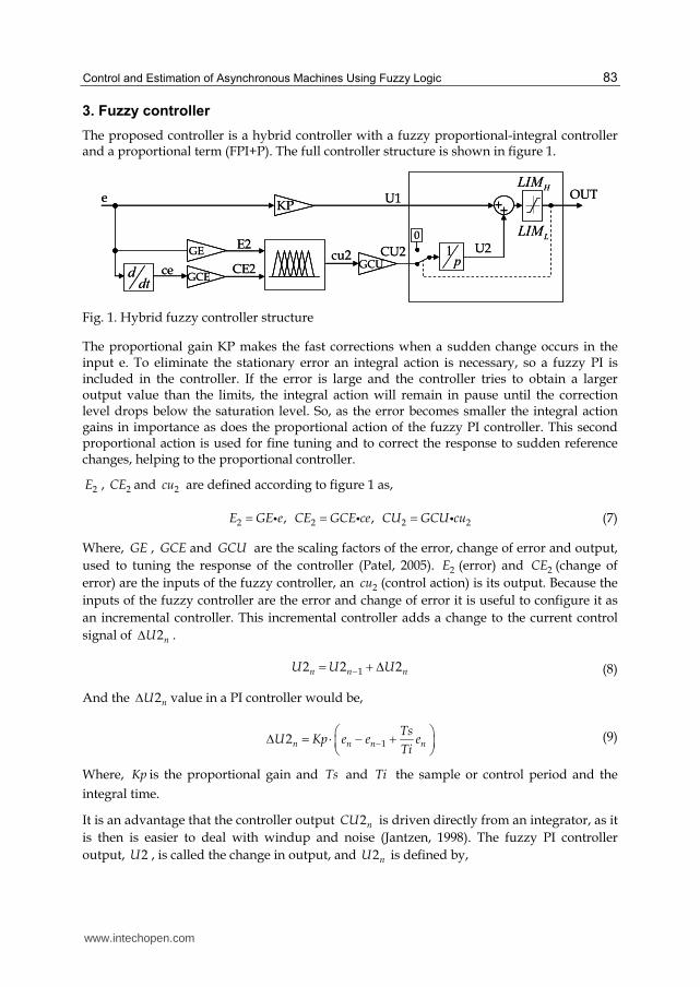
3. Fuzzy controller
The proposed controller is a hybrid controller with a fuzzy proportional-integral controller and a proportional term (FPI+P). The full controller structure is shown in figure 1.
KP
ddt
++
0
1p
GE
GCEGCUCE2ce
E2cu2 CU2
e U1
U2
OUTHLIM
LLIM
KP
ddt
++++
0
1p
GE
GCEGCUCE2ce
E2cu2 CU2
e U1
U2
OUTHLIM
LLIM
Fig. 1. Hybrid fuzzy controller structure
The proportional gain KP makes the fast corrections when a sudden change occurs in the input e. To eliminate the stationary error an integral action is necessary, so a fuzzy PI is included in the controller. If the error is large and the controller tries to obtain a larger output value than the limits, the integral action will remain in pause until the correction level drops below the saturation level. So, as the error becomes smaller the integral action gains in importance as does the proportional action of the fuzzy PI controller. This second proportional action is used for fine tuning and to correct the response to sudden reference changes, helping to the proportional controller.
2E , 2CE and 2cu are defined according to figure 1 as,
2 2 2 2, ,E GE e CE GCE ce CU GCU cu (7)
Where, GE , GCE and GCU are the scaling factors of the error, change of error and output,
used to tuning the response of the controller (Patel, 2005). 2E (error) and 2CE (change of
error) are the inputs of the fuzzy controller, an 2cu (control action) is its output. Because the
inputs of the fuzzy controller are the error and change of error it is useful to configure it as
an incremental controller. This incremental controller adds a change to the current control
signal of 2nU .
12 2 2n n nU U U (8)
And the 2nU value in a PI controller would be,
12n n n n
TsU Kp e e e
Ti (9)
Where, Kp is the proportional gain and Ts and Ti the sample or control period and the
integral time.
It is an advantage that the controller output 2nCU is driven directly from an integrator, as it
is then is easier to deal with windup and noise (Jantzen, 1998). The fuzzy PI controller
output, 2U , is called the change in output, and 2nU is defined by,
www.intechopen.com

Fuzzy Logic – Controls, Concepts, Theories and Applications
84
2 2n ii
U cu GCU Ts (10)
The integrator will add only if L n HLIM OUT LIM and 2 0icu . The value of
2cu according to the inputs is,
2 ,n n ncu f GE e GCE ce (11)
The function f is the fuzzy input-output map of the fuzzy controller. If it were possible to
take the function f as a linear approximation, considering equations (8-11), the gains related
to the conventional PI would be,
Kp GCE GCU (12)
1 GE
Ti GCE (13)
These relations had shown the importance of the scaling factors. High values of GE produce
a short rise time when a step reference is introduced but also a high overshot and a long
settling time could arise. The system may become oscillatory and even unstable. If GE is low
the overshot will decrease or disappear and the settling time increases. High values of GCE
have the same effect as small values of GE and vice versa.
High values of GCU originate a short rise time and overshot when a step reference is
introduced. If GCU is small the system gain is small and the rise time increases.
The global output value of the hybrid fuzzy controller is,
if
if
if
1 2
1 2
, 1 2
n H n n H
n L n n L
n
n n n n L n n Hi
OUT LIM U U LIM
OUT LIM U U LIM
OUT KP e f GE e GCE ce GCU Ts LIM U U LIM
(14)
The output of the controller is limited according to the maximum value of the hybrid fuzzy
controller, for example for a speed controller the limit will be the maximum admissible
torque and for the current controllers the limit will be the maximum admissible voltage of
the machine.
For a practical implementation of the fuzzy controllers on a DSP the fuzzy membership
functions of the antecedents and consequents are triangular and trapezoidal types because
the calculus complexity is lower than the calculus complexity when are used Gaussian or
Bell membership functions.
With the information of the plant model, the fuzzy sets and their linguistic variables are
defined for the antecedents and consequents. The control strategy has to be implemented
based on the engineer experience and if it is possible using simulation tools. The control
strategy is stored in the rule-base in the form If-Then and an inference strategy will be
chosen.
www.intechopen.com

Control and Estimation of Asynchronous Machines Using Fuzzy Logic
85
Then the system is ready to be tested to see if the closed-loop specifications are met. First
simulations will be carried analyzing the dynamic behaviour and the stability of the plant
and finally the adjustment will be tested and adjusted again in the real machine control
platform.
To get the rule-base of the controller the reference and feedback values are compared and
the control action is determined to correct the deviation between reference and feedback.
As an example, in the speed loop a positive increase of the speed error because the real
speed is lower than the reference, must force to the controller to increase their output or
torque reference, Te, to increase the machine speed as detailed in equation 6. Something
similar happens with the change of error; if the change of error is positive big, that means
that the machine is decelerating, then the controller has to increase the torque to reduce
the effect, so the controller has to produce a positive big output to increase the
electromagnetic torque.
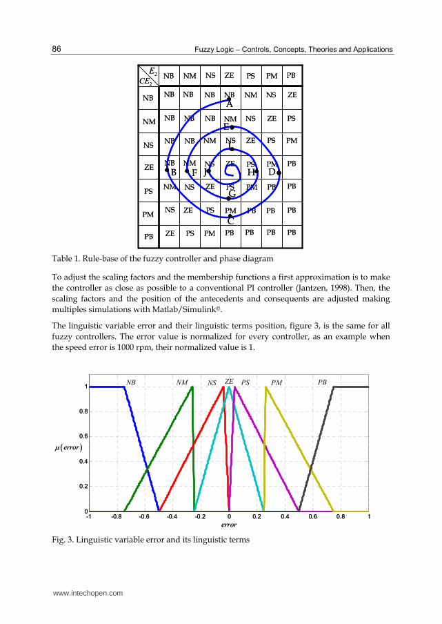
For another error and change of error combinations, the base-rule of table 1 applied to the
fuzzy controller shows a phase trajectory reducing the error as shown in figure 2. This is
valid for the speed, flux and current loops. The base-rule of table 1 characterizes the control
objectives and it is shown as a matrix with the phase trajectory superimposed. The dynamic
behaviour of the controller to make zero the error will depend on the antecedents and
consequents position, on the selected inference strategy, on the used defuzzification method
and on the scaling factors.
Reference
Feedback
2E
2CE
t
Reference
Feedback
2E
2CE
t
Fig. 2. Fuzzy controller phase diagram when used table 1
The meaning of the linguistic terms used in table I are: NB, negative big; NM, negative
medium; NS, negative small; ZE, zero; PS, positive small; PM, positive medium and PB,
positive big.
Table 1 indicates the use of 49 rules. The first is read as,
If 2E is Negative Big and 2CE is Negative Big Then 2cu is Negative Big
www.intechopen.com
Fuzzy Logic – Controls, Concepts, Theories and Applications
86
2CE2E NB NM NS ZE PS PM PB
NB
NM
NS
ZE
PS
PM
PB
NB NB NB NB NM NS ZE
ZE
ZE
ZE
ZE
ZE
ZE
NB
NB
NB
NM
NS
NS
NS
NS
NS
NM
NM
NM
NB
NB NB
PB
PB
PB
PB
PB
PB
PBPBPBPMPS
PBPM
PM
PM
PM
PS
PS
PS
PS
PS
A
B
C
D
E
F
G
H
I
J
2CE2E NB NM NS ZE PS PM PB
NB
NM
NS
ZE
PS
PM
PB
NB NB NB NB NM NS ZE
ZE
ZE
ZE
ZE
ZE
ZE
NB
NB
NB
NM
NS
NS
NS
NS
NS
NM
NM
NM
NB
NB NB
PB
PB
PB
PB
PB
PB
PBPBPBPMPS
PBPM
PM
PM
PM
PS
PS
PS
PS
PS
A
B
C
D
E
F
G
H
I
J
Table 1. Rule-base of the fuzzy controller and phase diagram
To adjust the scaling factors and the membership functions a first approximation is to make
the controller as close as possible to a conventional PI controller (Jantzen, 1998). Then, the
scaling factors and the position of the antecedents and consequents are adjusted making
multiples simulations with Matlab/Simulink©.
The linguistic variable error and their linguistic terms position, figure 3, is the same for all
fuzzy controllers. The error value is normalized for every controller, as an example when
the speed error is 1000 rpm, their normalized value is 1.
-1 -0.8 -0.6 -0.4 -0.2 0 0.2 0.4 0.6 0.8 10
0.2
0.4
0.6
0.8
1NB NM NS ZE PS PM PB
error
error
-1 -0.8 -0.6 -0.4 -0.2 0 0.2 0.4 0.6 0.8 10
0.2
0.4
0.6
0.8
1NB NM NS ZE PS PM PB
error
error
Fig. 3. Linguistic variable error and its linguistic terms
www.intechopen.com

Control and Estimation of Asynchronous Machines Using Fuzzy Logic
87
The linguistic variable change of error and their linguistic terms position, figure 4, is also the same for all fuzzy controllers. The change of error value is normalized for every controller.
-1 -0.8 -0.6 -0.4 -0.2 0 0.2 0.4 0.6 0.8 10
0.2
0.4
0.6
0.8
1 NB NM NS ZE PS PM PB
c error
c error
-1 -0.8 -0.6 -0.4 -0.2 0 0.2 0.4 0.6 0.8 10
0.2
0.4
0.6
0.8
1 NB NM NS ZE PS PM PB
c error
c error
Fig. 4. Linguistic variable change of error and its linguistic terms
The linguistic variable of the control action or consequent and the position of its linguistic
terms are shown in figure 5. The values are normalized, where a value of 20 in the real
control action is normalized to 1.
-1 -0.8 -0.6 -0.4 -0.2 0 0.2 0.4 0.6 0.8 10
0.2
0.4
0.6
0.8
1 NB NM NS ZE PS PM PB
Control action
Control action
-1 -0.8 -0.6 -0.4 -0.2 0 0.2 0.4 0.6 0.8 10
0.2
0.4
0.6
0.8
1 NB NM NS ZE PS PM PB
Control action
Control action
Fig. 5. Control action linguistic terms
In figure 6, the fuzzy controller surface can be seen. The used implication method is the
AND method or min (minimum), which truncates the output fuzzy set and as aggregation
the S-norm max (maximum) has been used. The used defuzzification method is the centroid
or center of gravity, equation 15.
www.intechopen.com

Fuzzy Logic – Controls, Concepts, Theories and Applications
88
T
oT
y yy
y
(15)
-1-0.5
00.5
1
-1
-0.5
0
0.5
1-1
-0.5
0
0.5
1
D a
cció
n d
e c
ontr
ol
control
action
c error error-1
-0.50
0.51
-1
-0.5
0
0.5
1-1
-0.5
0
0.5
1
D a
cció
n d
e c
ontr
ol
control
action
c error error
Fig. 6. Fuzzy controller surface
As it can be seen in figure 3 and 4, the linguistic variables are joined close to zero, showing a
higher sensibility in this area. For this reason the slope of the surface in figure 6 is high in a
surrounding area around the point (0,0,0).
4. Squirrel-cage machine control
A schematic diagram of the induction motor indirect vector control with the fuzzy PI + P
controllers is shown in figure 7. The scheme is obtained after operating with the machine
equations and using the rotor flux reference system as shown in figure 8.
DCV
speed
flux
torque
I magnetizing
d q
SVPWM
SVPWM*sV AS
BS
CS*sV
sI
r
a b c r
d q sI
Estimator
e
sdI
sqI
m*m
r
r
* r
r IM
sdI e s sqL I
m
e rd s sd
r
LL I
L
e
*
eT
eTK r
mP
DCV
speed
flux
torque
I magnetizing
d q
SVPWM
SVPWM*sV AS
BS
CS*sV
sI
r
a b c r
d q sI
Estimator
e
sdI
sqI
m*m
r
r
* r
r IM
sdI e s sqL I
m
e rd s sd
r
LL I
L
e
*
eT
eTK r
mP
Fig. 7. Squirrel cage control structure
The rotor flux reference system makes possible the control of the AC machine as a DC machine, allowing the control of the machine torque with the stator current q component and the flux with the d component of the same current as can be deducted from equations 2 to 6. A scheme showing these equations is shown in figure 9.
www.intechopen.com

Control and Estimation of Asynchronous Machines Using Fuzzy Logic
89
sI
sdIsqIr rd
d
q
er
sle
r rotor shaft
rotor fluxsI
sdIsqIr rd
d
q
er
sle
r rotor shaft
rotor flux
Fig. 8. Rotor flux reference system
1
1 r
r
LpR
sdImL
mI r
3
2
m
r
LPL
sqI eT 1
B pJ
LT
m
1
1 r
r
LpR
sdImL
mI r
3
2
m
r
LPL
sqI eT 1
B pJ
LT
m
Fig. 9. Torque, flux and speed control structure in the rotor flux reference system
The speed error is the input of a hybrid fuzzy controller and the output of FPI+P controller will generate the torque producing stator current component command Isq. The flux controller generates the flux producing stator current component Isd according to the flux-speed profile. Both currents are the input of two controllers to produce the stator voltages in the synchronous reference and then transformed to the stationary reference system to generate in the inverter the voltage vector for the motor.
The real platform to test the asynchronous motor and its main characteristics used also for the simulation purpose are shown in figure 10.
FPGA and signalconditioning
PC with DS1103
a , ,b ci i ia , ,b cu u u
dcu
3 380x V
6xPWM
LT
*
LT
mm
PMSM IM
FPGA and signalconditioning
PC with DS1103
a , ,b ci i ia , ,b cu u u
dcu
3 380x V
6xPWM
LT
*
LT
mm
PMSM IM
Rated speed
1440r.p.m.
Rated Torque 50Nm
Nominal current 14A
Frequency 50Hz
J = 0.038Kg*m2
B = 0.008Kg*m2/s
P = 2 pole-pairs
Rr = 0.57ΩRs = 0.81Ω
Lm = 0.117774H
Lr = 0.121498H
Ls = 0.120416H
Voltage 380V III-Y
Rated speed
1440r.p.m.
Rated Torque 50Nm
Nominal current 14A
Frequency 50Hz
J = 0.038Kg*m2
B = 0.008Kg*m2/s
P = 2 pole-pairs
Rr = 0.57ΩRs = 0.81Ω
Lm = 0.117774H
Lr = 0.121498H
Ls = 0.120416H
Voltage 380V III-Y
Fig. 10. Induction motor rig test and asynchronous motor main characteristics
www.intechopen.com

Fuzzy Logic – Controls, Concepts, Theories and Applications
90
The real system is based on a DS1103 board and is programmed using the software
Matlab/Simulink©. The board controls the IM inverter generating the SVPWM pulses
(dSPACE©, 2005). The speed is measured with a 4096 impulse encoder via a FPGA
connected to the DS1103 using the multiple period method (Cortajarena et al., 2006).
4.1 Torque or current control
As mentioned and shown in figure 9, the torque of the machine is controlled with the stator
current q component and the flux with the d component. The relation between the torque Te
and the stator current q component is,
3
2
Te
me r sq
r
K
LT P I
L
(16)
So first, torque and current magnetizing controllers will be adjusted. In a classical PI
controller the proportional term for a bandwidth of 2500 rad/s and a phase margin of 80º
with the machine parameters given in figure 10 is 0.05. For the adjustment of the hybrid
fuzzy controller KP will be 0.025, half of the proportional term in the PI. The scaling factors
adjusted after simulations for the current controllers are 150, 0.03GE GCE and
8GCU . The regulators maximum and minimum limits are ±310V, the maximum motor
phase voltage.
error
control
action
410x
change of error
error
control
action
410x
change of error
Fig. 11. Stator current q component controller fuzzy surface and trajectory after current step of figure 12
Figure 11 shows the hybrid fuzzy stator q current controller surface and the trajectory when
a step reference of -20 amperes is produced, and after 200 ms another step of 20 amperes as
shown in figure 12 is applied to the torque controller.
www.intechopen.com

Control and Estimation of Asynchronous Machines Using Fuzzy Logic
91
0.95 1 1.05 1.1 1.15 1.2 1.25-25
-20
-15
-10
-5
0
5
10
15
20
25
t(s)
Isq
0.95 1 1.05 1.1 1.15 1.2 1.25-20
-10
0
10
20
30
40
50
t(s)
Err
or
0.95 1 1.05 1.1 1.15 1.2 1.25-4
-3
-2
-1
0
1
2
3x 10
4
t(s)
Ch
ang
e o
f er
ror
Ref
Fdbk
Fig. 12. Stator current q component step reference and feedback, error for the step, and change of error
When the step reference is -20 amperes the feedback or real stator q current reaches the real value quickly, it takes 2 ms. The trajectory on the fuzzy surface for this step is the green line in the surface showing how the change of error and the error are decreasing to zero in about 2 ms. When the step reference goes from -20 to 20 amperes the feedback or real stator q current reaches the real value in 3 ms. The trajectory on the fuzzy surface for this step is the red line in the surface showing how the change of error and the error are decreasing to zero due to the value of the control action.
4.2 Speed and rotor flux control
Once the current loops have been adjusted, the speed and flux loops will be adjusted. As mentioned and shown in figure 9, the machine speed is regulated adjusting the torque command and the flux adjusting the stator current d component.
In a classical speed PI controller the proportional term for a bandwidth of 750 rad/s and a
phase margin of 80º with the machine parameters given in figure 10 is 0.5. For the adjustment
of the hybrid fuzzy controller KP will be 0.4, a little bit smaller than the proportional term in
the PI. The scaling factors adjusted after simulations for the speed controllers are
2, 0.01GE GCE and 300GCU . The regulators maximum and minimum limits are ±50
Nm, the maximum motor torque or a stator current q component of 20 amperes.
Figure 13 shows the hybrid fuzzy speed controller surface and the trajectory when a step reference from -1000 rpm to 1000 rpm and again to -1000 rpm as shown in figure 14 is applied to the speed controller.
When the step goes from -1000 to 1000 rpm the trajectory on the fuzzy surface for this step is the green line, showing how the change of error and the error are decreasing to zero in about 180 ms. When the step reference goes from 1000 to -1000 rpm the feedback or real speed reaches the real value in 180 ms. The trajectory on the fuzzy surface for this step is the red line, showing how the change of error and the error are decreasing to zero due to the value of the control action.
www.intechopen.com

Fuzzy Logic – Controls, Concepts, Theories and Applications
92
error
control
action
410x
change of error error
control
action
410x
change of error
Fig. 13. Speed controller fuzzy surface and trajectory after speed step of figure 14
0.6 0.8 1 1.2-1500
-1000
-500
0
500
1000
1500
t(s)
Spe
ed (
rpm
)
0.6 0.8 1 1.2-2500
-2000
-1500
-1000
-500
0
500
1000
1500
2000
2500
t(s)
Err
or
0.6 0.8 1 1.2-1.5
-1
-0.5
0
0.5
1
1.5x 10
4
t(s)
Ch
an
ge
of
err
or
Ref
Fdbk
Fig. 14. Speed step reference and feedback, error for the step, and change of error
When the change of error is high, the controller output is at its maximum limit, and when the change of error decreases the control action also decreases close to zero as it can be seen in the trajectory of figure 13. The error and change of error trajectory of the surface in figure 13 correspond to the values represented in figure 14. The control action contribution can be obtained from the fuzzy controller surface.
Figure 15 shows the response of the real asynchronous motor of figure 10 when a speed step
is applied to the machine and later a load torque of 40 Nm after 0.3 s. Three classes of speed
controllers are tested to see the response and compare them. A classical PI controller with a
750 rad/s and a phase margin of 80º, the adjusted hybrid Fuzzy PI + P controller and a
Fuzzy controller without the KP term and 2, 0.06GE GCE and 300GCU .
www.intechopen.com

Control and Estimation of Asynchronous Machines Using Fuzzy Logic
93
0 0.05 0.1 0.15 0.2 0.25 0.3 0.35 0.4100
200
300
400
500
600
700
Spe
ed (
rpm
)
0 0.05 0.1 0.15 0.2 0.25 0.3 0.35 0.4-5
0
5
10
15
20
25
30
t(s)
Isq
(A
)
Reference
FPI+P
PI
Fuzzy
FPI+P
Fuzzy
PI
Fig. 15. Top, speed step and response when PI, Fuzzy and Fuzzy PI + P controllers are used. Bottom, torque current controllers output
To compare the controllers, table 2 shows time domain specifications and performance
criteria, integrated absolute error (IAE), the integral of time-weighted absolute error (ITAE),
the integral of the square of the error, ISE, and the integral of time multiply squared error
(ITSE).
Delay time
Rise time
Settling time
% Overshoot
IAE ITAE ISE ITSE
PI 1.4ms 42ms 56ms 3 97470 6754 2.23e7 3.29e5
Fuzzy 3.2ms 77ms 80ms 0 1.28e5 7579 2.86e7 4.8e5
FPI+P 1.4ms 42ms 47ms 0 96270 6000 2.23e7 3.01e5
Table 2. Time domain specifications and performance criteria for three classes of controllers
Very similar results are obtained with the PI and FPI+P controllers, although according to
the performance criteria the hybrid fuzzy controller is slightly better. The worst controller is
the fuzzy controller as it is shown in table 2 and figure 15.
To check the control of the machine with the hybrid fuzzy controller the machine will be
forced to run at a speed higher than the nominal value. In such conditions the machine rotor
flux has to decrease because the inverter DC voltage can’t be higher, so the torque and stator
current q component relation is changing as shown in equation 16 and figure 9. This change
should be taken in consideration in a classical PI regulator. In the hybrid fuzzy controller the
adjustment done with the linguistic variables and the scaling factors shows that the control
works properly. In figure 16, the left signals correspond to the real signals obtained whit the
machine of the test rig and the right side signals are the simulated in the same conditions
than the real case. Because the speed is higher than nominal value, the flux decreases below
the nominal value, to do this the stator current d component decreases and increases when
www.intechopen.com

Fuzzy Logic – Controls, Concepts, Theories and Applications
94
the flux is increasing to the nominal value. The q component of the stator current related
with the torque increases when the machine is accelerating and decreases when the machine
decelerates.
The speed regulation in the flux weakening region is good, and real platform signals and simulations corroborate the hybrid fuzzy good performance.
The flux hybrid fuzzy controller scaling factors are 200, 20GE GCE and 100GCU . To
evaluate the flux regulation, the rotor flux reference and feedback values could be compared
in the flux weakening shown in figure 16. Both are very similar showing a very good flux
regulation and the flux controller output corresponds with the stator current d component
shown in the same figure.
0 0.2 0.4 0.6 0.8 1 1.2 1.4 1.6 1.8 20
1000
2000
3000
Sp
eed
(rp
m)
0 0.2 0.4 0.6 0.8 1 1.2 1.4 1.6 1.8 20.4
0.6
0.8
1
Ro
tor
flu
x (
Wb
)
0 0.2 0.4 0.6 0.8 1 1.2 1.4 1.6 1.8 2-20
0
20
Isd
q (
A)
0 0.2 0.4 0.6 0.8 1 1.2 1.4 1.6 1.8 2-20
0
20
t(s)
Is (
A)
0 0.2 0.4 0.6 0.8 1 1.2 1.4 1.6 1.8 20
1000
2000
3000
Sp
eed
(rp
m)
0 0.2 0.4 0.6 0.8 1 1.2 1.4 1.6 1.8 20.4
0.6
0.8
1
Roto
r flux (
Wb)
0 0.2 0.4 0.6 0.8 1 1.2 1.4 1.6 1.8 2-10
0
10
20
Isd
q (
A)
0 0.2 0.4 0.6 0.8 1 1.2 1.4 1.6 1.8 2-20
0
20
t(s)
Is (
A)
Ref
Fdbk
Ref
Fdbk
Isd
Isq
Isalfa
Isbeta
Ref
Fdbk
Ref
Fdbk
Isd
Isq
Isalfa
Isbeta
Fig. 16. Left, real machine signals, speed, flux and stator currents. Right, simulated signals
4.3 Speed estimation
There are in literature many techniques of sensorless control. The first group is based on the fundamental mathematical model of the machine, that is, the flux density distribution in the air gap is sinusoidal. All these models depend on the machine parameters so the accuracy of the estimators will depend on different manner of the precision of these parameters. It is not possible with these techniques to achieve a stable and precise operation at very low speed.
www.intechopen.com

Control and Estimation of Asynchronous Machines Using Fuzzy Logic
95
The second group of techniques is based on the anisotropic properties of the machine. Techniques like rotor slot ripple or main inductance saturation are used in this group.
From equations 2 and 4, considering rotor voltage zero, and after Laplace transformation of the respective space vectors the rotor flux will be,
, ,( ) ( )
1
mr dq s dq
r re r
r r
Lp i p
L Lp j
R R
(17)
Operating with equations 1 to 4 the next equation is obtained,
,
2,
, , ,
s dq
s dq m m rs s dq s r e s dq r r dq
r r r
vr
di L L RL v R R j i j
dt L L L
(18)
It can be seen the induced voltage from the rotor into the stator as ,s dqrv .
As the feeding voltage vector of the stator approaches zero frequency, the rotor speed
approaches zero. If the equation 18 is observed in the stationary reference frame, e =0, and
using equation 17, ,s dqrv is calculated when p→0,
2
, , ,20 0lim
r
m rs s s
pr
L Rvr vr i
L (19)
The equation 19 is independent of r when stator frequency is close to zero, so the
variations of rotor speed have no influence on the stator equation 18 and this makes
impossible to detect a speed variation on the stator current. So the mechanical speed of the
rotor becomes not observable. Instead of this, when the magnitude of the induced voltage
from the rotor into the stator is substantial, its value can be determined and the rotor state
variables are then observable. So, there will be a limitation for very low speed operation due
to the dc offset components in the measured stator currents and voltages.
The minimum stator frequency must be superior to zero to have an appropriate relation between induced voltage from the rotor into the stator and also to reduce the noise and parameters mismatch influence (Holtz, 1996).
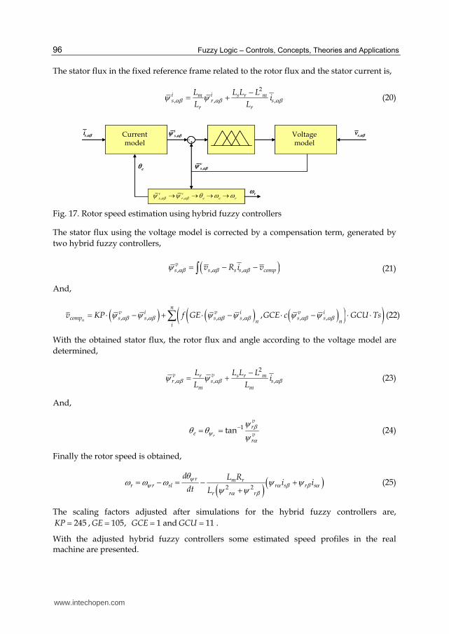
The rotor speed estimator used, figure 17, is based on the fundamental mathematical model of the machine. The rotor speed is obtained with the derivative of the rotor flux angle minus the slip speed, see figure 8. The precision of the estimator has a great dependence on motor parameters and at low speeds a small error (offset for example) in the stator voltage can suppose an estimation error.
The rotor flux estimator contains two models, the open loop current model, which is supposed to produce an accurate estimation at low speed range, and an adaptive voltage model for a medium high speed range of operation. The transition between both models is adjusted by two hybrid fuzzy controllers, reducing the problems due to stator resistance and pure integrators at low speed.
www.intechopen.com
Fuzzy Logic – Controls, Concepts, Theories and Applications
96
The stator flux in the fixed reference frame related to the rotor flux and the stator current is,
2
, , ,i im s r ms r s
r r
L L L Li
L L (20)
Current model
,si Voltage model
,sv, i
s
, v
s
, , v v
s r e e r
e
r
Current model
,si Voltage model
,sv, i
s
, v
s
, , v v
s r e e r
e
r
Fig. 17. Rotor speed estimation using hybrid fuzzy controllers
The stator flux using the voltage model is corrected by a compensation term, generated by
two hybrid fuzzy controllers,
, , ,vs s s s compv R i v (21)
And,
, , , , , ,,n
nv i v i v i
comp s s s s s sn n
i
v KP f GE GCE c GCU Ts (22)
With the obtained stator flux, the rotor flux and angle according to the voltage model are
determined,
2
, , ,v vr s r mr s s
m m
L L L Li
L L (23)
And,
1tanr
vr
e vr
(24)
Finally the rotor speed is obtained,
2 2
r m rr r sl r s r s
r r r
d L Ri i
dt L
(25)
The scaling factors adjusted after simulations for the hybrid fuzzy controllers are,
245KP , 105, 1GE GCE and 11GCU .
With the adjusted hybrid fuzzy controllers some estimated speed profiles in the real machine are presented.
www.intechopen.com

Control and Estimation of Asynchronous Machines Using Fuzzy Logic
97
Figure 18 shows three speed references when the machine is unloaded. The speed reference
of the left figure is a square signal from -1000 to 1000 rpm. The estimated speed is used as
feedback signal and for check purposes the measured or real speed is also shown. As can be
seen the real and estimated speeds are very similar. The speed reference of the middle figure
is sinusoidal and the reference, estimated and real signals are very similar, showing a good
regulation and speed estimation. The right figure shows a random speed reference crossing
during 2 seconds at a speed close to zero rpm, where the speed is poorly observable. The
reference, estimated and real signals are very similar even at zero speed for a short time.
0 0.5 1 1.5
-1000
-500
0
500
1000
t(s)
Spe
ed (
rpm
)
0 0.5 1 1.5-600
-400
-200
0
200
400
600
t(s)
Spe
ed (
rpm
)
0 2 4 6 8 10 12
-1000
-500
0
500
1000
t(s)
Spe
ed (
rpm
)
Ref
Real
Estim.
Ref
Real
Estim.
Ref
Real
Estim.
Fig. 18. Sensorless control for different speed references when the load torque is cero
0 0.2 0.4 0.6 0.8 1 1.2 1.4 1.6 1.8 2100
150
200
250
300
t(s)
Sp
eed
(rp
m)
0 0.2 0.4 0.6 0.8 1 1.2 1.4 1.6 1.8 2-20
0
20
40
60
t(s)
To
rqu
e (N
m)
0 0.2 0.4 0.6 0.8 1 1.2 1.4 1.6 1.8 2100
150
200
250
300
t(s)
Sp
eed
(rp
m)
0 0.2 0.4 0.6 0.8 1 1.2 1.4 1.6 1.8 2-60
-40
-20
0
20
t(s)
To
rqu
e (N
m)
Ref
Real
Estim.
Ref
Real
Ref
Real
Estim.
Ref
Real
Fig. 19. Sensorless control for 200 rpm and torque step loads of ±30Nm
Figure 19 shows the speed estimation when a load perturbation of ±30 Nm is applied to the
machine. There is an error between the real speed and the estimated speed when the
machine is loaded due to parameters mismatch.
www.intechopen.com

Fuzzy Logic – Controls, Concepts, Theories and Applications
98
5. Doubly fed induction generator control
A doubly fed induction generator (DFIG) vector control with the fuzzy PI + P controllers is shown in figure 20. The scheme is obtained after operating with the machine equations and using the stator flux reference system shown in figure 21.
d q
SVPWM
SVPWM*
rV AS
DFIG
rI rI
raI
rbI
e
*
rqI
rdI
rqI d q
a b c
*
rdI
*
rdV
*
rV
Park Clarke
rI
rV
DCV
BS
CS
Estimator
s
saI
sbI
saV
sbV
a b c
, s sI I
, Vs sV sI
sV
r
s
Uncoupling
*
rqV
e r r rqL I
e r r rdL I
, r r
*
r
*Q
s
Grid
P
Calculation
*
ratedP
**
min 0
s
s
V
V
s
s
I
I
wv
*
rwv
Pitch control
sV s
*P
Equ. 31
Equ. 30
sV
d q
SVPWM
SVPWM*
rV AS
DFIG
rI rI
raI
rbI
e
*
rqI
rdI
rqI d q
a b c
*
rdI
*
rdV
*
rV
Park Clarke
rI
rV
DCV
BS
CS
Estimator
s
Estimator
s
saI
sbI
saV
sbV
a b c
, s sI I
, Vs sV sI
sV
r
s
Uncoupling
*
rqV
e r r rqL I
e r r rdL I
, r r
*
r
*Q
s
Grid
P
Calculation
*
ratedP
**
min 0
s
s
V
V
s
s
I
I
wv
*
rwv
*
rwv
*
rwv
*
rwv
Pitch control
sV s
*P
Equ. 31
Equ. 30
sV
Fig. 20. DFIG control structure
d
q
rI
rI
rI
rdI
rqI
r
e
Reference system
fixed to the stator
Reference system
linked to the rotor
Reference system
linked to the s
s
se
r
s sqV V
d
q
rI
rI
rI
rdI
rqI
r
e
Reference system
fixed to the stator
Reference system
linked to the rotor
Reference system
linked to the s
s
se
r
s sqV V
Fig. 21. DFIG control reference systems
The converter Back to Back configuration provides to the DFIG the ability of reactive power control. Using the appropriate reference system it is possible to decouple the active and reactive power control by the independent control of the rotor excitation current. Due to the bi-directional power converter in the rotor side, the DFIG is able to work as a generator in
www.intechopen.com

Control and Estimation of Asynchronous Machines Using Fuzzy Logic
99
the sub-synchronous (slip speed is positive, s>0) and super-synchronous (slip speed is negative, s<0) operating area (Hansen et al., 2007).
When the reference system is linked to the stator flux, as it can be seen in figure 21, the
stator flux q component is zero, and when operating with equation 3 the next two equations
are obtained,
= s m
sd rds s
Li i
L L
(26)
=m
sq rqs
Li i
L (27)
This means that the stator current can be controlled with the rotor current. Taking into
account that the stator resistance is small, the stator flux can be considered constant and its
value is,
s
se
V (28)
The stator voltage d component is almost zero because the reference system is oriented
along the stator flux, so considering that the stator active and reactive power is,
and3 3
2 2s sd sd sq sq s sq sd sd sqP v i v i Q v i v i (29)
It can be obtained that,
3
2m
s e s rqs
LP i
L (30)
And,
3
2s m
s s rde s s
V LQ V i
L L (31)
Equations 30 and 31 showed that the stator active power is controlled with the q component
of the rotor current and the stator reactive power with the rotor current d component. In
figure 20 can be seen both hybrid fuzzy controllers to regulate the d and q rotor current
components.
The real platform to test the double feed induction generator and its main characteristics
used also for the simulation purpose are shown in figure 22.
The real system is based on a DS1103 board and is programmed using the software
Matlab/Simulink©. The board controls the inverters in a Back to Back configuration generating
the SVPWM pulses (dSPACE©, 2005). The grid connected inverter, is regulated keeping the DC
www.intechopen.com

Fuzzy Logic – Controls, Concepts, Theories and Applications
100
bus voltage constant. The speed of the DFIG is measured with a 4096 impulse encoder
connected to the DS1103 using the frequency method (Cortajarena et al., 2006).
First, the inner current loops are adjusted. The used hybrid fuzzy controller is the same as have been used in the squirrel cage machine. The scaling factors have been adapted after realizing multiple simulations and finally adjusted in the DFIG test rig.
FPGA and signalconditioning
PC with DS1103
sa
sb
sc
i
i
i
a , ,b cu u udcu
3 380x V
6xPWM
mm
PMSMDFIG
6xPWM
3 380x V
sa , ,sb sci i i
ga , ,gb gci i iga , ,gb gci i i
ra , ,rb rci i i
*m FPGA and signalconditioning
PC with DS1103
sa
sb
sc
i
i
i
a , ,b cu u udcu
3 380x V
6xPWM
mm
PMSMDFIG
6xPWM
3 380x V
sa , ,sb sci i i
ga , ,gb gci i iga , ,gb gci i i
ra , ,rb rci i i
*m
J = 0.045Kg*m2
B = 0.02Kg*m2/s
P = 2 pole-pairs
Rr = 0.275ΩRs = 0.325Ω
Lm = 0.0664H
Lr = 0.0678H
Ls = 0.0681H
Stator voltage 380V
Rotor voltage 190V
Frequency 50Hz
Rated current 14A
Rated Torque 50Nm
Rated speed 1440r.p.m.
J = 0.045Kg*m2
B = 0.02Kg*m2/s
P = 2 pole-pairs
Rr = 0.275ΩRs = 0.325Ω
Lm = 0.0664H
Lr = 0.0678H
Ls = 0.0681H
Stator voltage 380V
Rotor voltage 190V
Frequency 50Hz
Rated current 14A
Rated Torque 50Nm
Rated speed 1440r.p.m.
Fig. 22. DFIG rig test and its main characteristics
To test the performance of the hybrid fuzzy controller it will be compared to a conventional PI controller. In a classical PI controller the proportional term for a bandwidth of 3000 rad/s and a phase margin of 80º with the machine parameters given in figure 22 is 0.015. For both current controllers, the proportional term KP will be 0.015 and the scaling factors are
300, 0.025GE GCE and 0.2GCU . The regulators maximum and minimum limits are
±1, equivalent to ±310 V per phase in the rotor.
Figure 23 shows the hybrid fuzzy rotor q current controller surface and the trajectory when a step reference from 10 to 20 amperes is produced. The feedback or real rotor q current reaches the real value quickly, it takes around 3 ms.
The trajectory on the fuzzy surface for this step shows how the error is moving around the high slope where the error is close to zero. In table 3, the performances of two controllers are summarized. The hybrid fuzzy and the conventional PI have similar dynamic response, showing the fuzzy controller a better performance when IAE, ITAE, ISE and ITSE indexes are used to evaluate the performance.
In a DFIG control there are two operating regions depending on the wind speed. Below the machine rated power, the blade pitch angle is set to zero degrees to get the maximum power. When the wind speed is sufficiently fast to get power from the wind higher than the rated power, enters into the second region. In this region the blade pitch angle controller
www.intechopen.com

Control and Estimation of Asynchronous Machines Using Fuzzy Logic
101
regulates the output power modifying the pitch angle to get the rated power from the generator without damage it.
control
action
change of error
410x
error
control
action
change of error
410x
error
Fig. 23. Rotor current q component controller fuzzy surface and trajectory after current step of figure 24
0 0.5 1 1.56
8
10
12
14
16
18
20
22
24
26
t(s)
Irq
(A
)
0 0.5 1 1.5-15
-10
-5
0
5
10
15
t(s)
Irq
err
or
(A
)
0 0.5 1 1.5-4
-3
-2
-1
0
1
2
3x 10
4
t(s)
Ch
ang
e o
f Ir
q e
rro
r (A
)
Ref
Fdbk
Fig. 24. Rotor current q component step reference and feedback, error for the step, and change of error
Delay time
Rise Time
Settling time
% Overshoot
IAE ITAE ISE ITSE
PI 1.2ms 1.2ms 4ms 20 8413 4110 11576 5105
FPI+P 1ms 1ms 3.5ms 20 7925 3880 10200 4510
Table 3. Time domain specifications and performance criteria for two classes of controllers
The power transmitted to the hub of a wind turbine can be expressed as,
www.intechopen.com

Fuzzy Logic – Controls, Concepts, Theories and Applications
102
2 31
( , )2
turb p air wP C R v (32)
Where ρair, is the mass density of the air, R is the radius of the propeller, Cp is the power
performance coe4fficient, vw is the wind speed, β is the pitch angle and is the blade tip
speed ratio and is defined as,
pr
w
R
v
(33)
and ωpr is the angular velocity of the propeller.
The power performance coefficient Cp, used according to the tip speed ratio and the pitch
angle for the DFIG is shown in figure 25.
Tip speed ratio, Pitch angle,
pC
Tip speed ratio, Pitch angle,
pC
Fig. 25. Power performance coefficient depending on tip speed ratio and pitch angle
Figure 26 shows for a pitch angle of 0º the obtained power from the wind according to the
propeller speed. The black line indicates the maximum power and the propeller speed to get
this power from every wind speed. When the obtained power reaches the machine rated
power, the wind energy is wasted changing the pitch angle and getting the rated power.
For a known wind speed and using figure 26, the propeller optimum speed and the power
are obtained. Then, with equation 30 the rotor q component is determined as reference.
The inertia of the blades turned by the drive is large and a real pitch actuator has thus limited capabilities. Its dynamics are non-linear with saturation limits on pitch angle (usually from 0 to 30º) and pitching speed rate around 10º/s.
www.intechopen.com

Control and Estimation of Asynchronous Machines Using Fuzzy Logic
103
0 1 2 3 4 5 6 70
2000
4000
6000
8000
10000
wpr(rad/s)
Pow
er
(W)
4m/s
6m/s
8m/s
10m/s
11m/s
0º
Rated power
Wind speed
0 1 2 3 4 5 6 70
2000
4000
6000
8000
10000
wpr(rad/s)
Pow
er
(W)
4m/s
6m/s
8m/s
10m/s
11m/s
0º
0 1 2 3 4 5 6 70
2000
4000
6000
8000
10000
wpr(rad/s)
Pow
er
(W)
4m/s
6m/s
8m/s
10m/s
11m/s
0 1 2 3 4 5 6 70
2000
4000
6000
8000
10000
wpr(rad/s)
Pow
er
(W)
4m/s
6m/s
8m/s
10m/s
11m/s
0º
Rated power
Wind speed
Fig. 26. Obtained wind power for a pitch angle of 0º, depending on wind speed and propeller speed
The actuator is modelled in closed loop with saturation of the pitch angle and a pitch rate limitation. This closed loop configuration with integrator, gives similar result as a first order transfer function but with limitation of the pitch rate (Bindner, 1999). If the pitch reference angle is outside the lower and higher limits, the integrator output is prevented from growing indefinitely.
The pitch control diagram is shown in figure 27, where P is the DFIG real power, Pmax
DFIG is the maximum admissible power for the DFIG and P* is the active power reference.
Tip speed ratio, Pitch angle,
pC
Tip speed ratio, Pitch angle,
pC
maxDFIGP
PP
1
p
Tip speed ratio, Pitch angle,
pC
Tip speed ratio, Pitch angle,
pC
maxDFIGP
PP
1
p
1
p
Fig. 27. Pitch control diagram
The pitching speed rate is fixed to 10º/s, the pitch angle is limited from 0 to 30º, the KP
value and the scaling factors adjusted after simulations ensuring stability for the pitch
controller are 0.003KP , 400, 0.24GE GCE and 0.1GCU . The hybrid fuzzy
regulator maximum and minimum limits are 0 to 30º as pitch angle reference limit.
Figure 28 left, shows the response of the pitch control when a wind speed step from 9m/s to 13m/s is produced. The obtained total power from the wind at 9m/s is 3800w and when the wind speed power is higher than the fixed 7000w, the pitch angle starts the regulation to limit the total power. The figure to the right shows the same signals for a random speed profile. When the wind speed is lower than 10m/s the pitch angle is zero, and all wind power is converted in electric power, but when the speed is higher, the pitch angle is regulated limiting the maximum power returned to the grid.
www.intechopen.com

Fuzzy Logic – Controls, Concepts, Theories and Applications
104
0 0.2 0.4 0.6 0.8 1 1.2 1.4 1.6 1.8 28
10
12
14
t(s)
Win
d s
pee
d (
m/
s)
0 10 20 30 40 50 605
10
15
20
t(s)
Win
d s
pee
d (
m/
s)
0 0.2 0.4 0.6 0.8 1 1.2 1.4 1.6 1.8 2-8000
-6000
-4000
-2000
t(s)
P (
w)
0 10 20 30 40 50 60-10000
-5000
0
t(s)P
(w
)
0 0.2 0.4 0.6 0.8 1 1.2 1.4 1.6 1.8 20
5
10
t(s)
Pit
ch a
ng
le (
º)
0 10 20 30 40 50 600
5
10
15
t(s)
Pit
ch a
ng
le (
º)
P actual
P rated
P actual
P rated
Fig. 28. Fuzzy pitch control performance when a step of wind speed and a random wind speed profile are produced
6. Parameter variations
As it was commented into the introduction, the fuzzy logic approach is based on linguistic
rules, and the controller robustness is high. To verify the above, the squirrel-cage motor is
replaced by a different one. The motor parameters change and without realizing any
adjustment in the controllers the speed regulation is tested in a motor control with
conventional PI controllers and with the proposed hybrid fuzzy controllers. The new
motor parameters are: Rr=1.2 Ω, Rs=1.5 Ω, Lm=0.108 H, Lr=0.12 H, Ls=0.12 H, J=0.038
Kg*m2.
Figure 29 shows the speed of the machine when there is a big noise in the stator alfa and
beta components; in fact the noise is very high. The speed reference is 1000 rpm and a load
step of 40 Nm is applied to the new machine, without readjusting the controllers, at 0.5s.
The left figure shows the response of the machine controlled with PI controllers. The
performance of the system becomes wrong when the load changes after 0.5s, the system
becomes instable. Instead, in the right figure the motor is controlled with the hybrid fuzzy
controllers adjusted in section 4. When the load torque is applied to the machine the speed
regulation after that moment is correct. This is an example of the robustness of the fuzzy
controller compared with the conventional PI controllers when there is noise in the
measurements, in this case stator current measurement.
www.intechopen.com

Control and Estimation of Asynchronous Machines Using Fuzzy Logic
105
0 0.1 0.2 0.3 0.4 0.5 0.6 0.7 0.8 0.9 1-100
-50
0
50
100
t(s)
Stat
or
curr
ent
(A)
0 0.1 0.2 0.3 0.4 0.5 0.6 0.7 0.8 0.9 1-100
-50
0
50
100
t(s)
Stat
or
curr
ent
(A)
0 0.1 0.2 0.3 0.4 0.5 0.6 0.7 0.8 0.9 10
200
400
600
800
1000
t(s)
Spee
d (
rpm
)
0 0.1 0.2 0.3 0.4 0.5 0.6 0.7 0.8 0.9 10
200
400
600
800
1000
t(s)
Spee
d (
rpm
)
Ref
Real
Ref
Real
Fig. 29. Speed regulation when there is a big noise in the stator current measurement. A load step of 40Nm is applied to the machine at 0.5s. Left, PI controllers. Right, hybrid fuzzy controllers
7. Conclusions
Control of asynchronous machines can be made relatively simple if the machine is
understood as a DC machine. This is obtained making the appropriate transformations of
reference systems. The squirrel cage machine has been used as a motor and hybrid fuzzy
controllers have been used to control the speed of the machine. The performance has been
compared with classical PI and fuzzy controllers, showing a better performance. Also a
speed estimator has been implemented using two hybrid fuzzy controllers. The speed
sensor has been replaced for the speed estimator to get a sensorless system.
The control of the double feed induction generator used in wind turbines has been studied.
First the main control equations are presented and then, the rotor current controllers are
implemented with the hybrid fuzzy controllers. The performance is compared to
conventional PI controllers, showing a slightly better performance. Also pitch control is
realized to limit the maximum power obtained from the wind. The real system shows how
the controller limits the maximum power properly.
All the proposed controllers have been simulated and compared to the real system to
validate the systems model. With the checked models, the adjustments to guarantee the
stability and to get good performance are done. Then, all of simulated hybrid fuzzy
controllers have been implemented in the real platforms giving good results.
www.intechopen.com

Fuzzy Logic – Controls, Concepts, Theories and Applications
106
Also, the robustness of the controlled system with the hybrid fuzzy controllers is demonstrated, compared with the conventional control implemented with conventional PI regulators.
8. References
Astrom, K.J. ; Hagglung, T. (1996). Automatic tuning of PID controllers. The Control Handbook. A CRC Handbook Published in Cooperation with IEEE Press 1996 CRC Press, Inc. pp 817-846.
Bindner, H. (1999). Active Control : Wind Turbine Model. Riso-R-920(EN). Riso National Laboratory, Roskilde, Denmark.
Cortajarena, J.A. ; Marcos,J. ; Alkorta, P. ; Vicandi, F.J. ; Alvarez, P. (2006). System to study induction motor speed estimators. Proceedings of SAAEI06. Gijón.
dSPACE©, (2005). Real –Time Interface. Implementattion Guide. Experiment Guide. For Realese 5.0. GmbH Paderborn, Germany.
Hansen, A.D. ; Sørensen, P. ; Iov, F. ; Blaabjerg, F. (2007) Overall control strategy of variable speed doubly-fed induction generator wind turbine. Proc. of Wind Power Nordic Conference, Chalmers University of Technology, Göteborg, Sweden, pp. 1-7.
Holtz, J. (1996). Methods for Speed Sensorless Control of AC Drives. Sensorless Control of AC Motor Drives. IEEE Press,pp21-29.
Jantzen, J. (1998). Tuning of Fuzzy PID Controllers. Tech. report no 98-H-871 (fpid). Technical University of Denmark, Lyngby.
Li, W. (1998). Design of a hybrid fuzzy logic proportional plus conventional integral-derivative controller. IEEE. Trans. Fuzzy Syst., Vol. 6, no. 4, pp 449-463.
Patel, A.V. (2005). Simplest Fuzzy PI Controllers under Various Defuzzification Methods. International Journal Of Computational Cognition. Vol. 3, no. 1, pp 21-34.
Vas, P. (1999). Artificial-Intelligent-Based Elecrical Machines and Drives. Application of Fuzzy, Neural, Fuzzy-Neural, and Genetic-Algorithm-Based Techniques. Oxford University Press, Inc., ISBN 0 19 859397 X, New York.
Won, C.Y. ; Bose, B.K. (1992). An Induction Motor Servo System with Improved Sliding Mode Control. IEEE Conf. Proceedings of IECON’92, pp. 60-66.
Zadeh, L.A. (1965). Fuzzy sets. Information and Control, Vol. 8 pp 338-353. Zhen, L. ; Xu, L. (1998). Sensorless Field Oriented Control of Induction Machines Based on a
Mutual MRAS Scheme. IEEE Trans. on Indust. Electonics. Vol 45. no.5. pp 824-830.
www.intechopen.com

Fuzzy Logic - Controls, Concepts, Theories and ApplicationsEdited by Prof. Elmer Dadios
ISBN 978-953-51-0396-7Hard cover, 428 pagesPublisher InTechPublished online 28, March, 2012Published in print edition March, 2012
InTech EuropeUniversity Campus STeP Ri Slavka Krautzeka 83/A 51000 Rijeka, Croatia Phone: +385 (51) 770 447 Fax: +385 (51) 686 166www.intechopen.com
InTech ChinaUnit 405, Office Block, Hotel Equatorial Shanghai No.65, Yan An Road (West), Shanghai, 200040, China
Phone: +86-21-62489820 Fax: +86-21-62489821
This book introduces new concepts and theories of Fuzzy Logic Control for the application and development ofrobotics and intelligent machines. The book consists of nineteen chapters categorized into 1) Robotics andElectrical Machines 2) Intelligent Control Systems with various applications, and 3) New Fuzzy Logic Conceptsand Theories. The intended readers of this book are engineers, researchers, and graduate students interestedin fuzzy logic control systems.
How to referenceIn order to correctly reference this scholarly work, feel free to copy and paste the following:
José Antonio Cortajarena, Julián De Marcos, Fco. Javier Vicandi, Pedro Alvarez and Patxi Alkorta (2012).Control and Estimation of Asynchronous Machines Using Fuzzy Logic, Fuzzy Logic - Controls, Concepts,Theories and Applications, Prof. Elmer Dadios (Ed.), ISBN: 978-953-51-0396-7, InTech, Available from:http://www.intechopen.com/books/fuzzy-logic-controls-concepts-theories-and-applications/control-and-estimation-of-ac-induction-machines-using-fuzzy-logic-