control and performance evaluation of a flywheel energy-storage system associated to a ...
TRANSCRIPT
1074 IEEE TRANSACTIONS ON INDUSTRIAL ELECTRONICS, VOL. 53, NO. 4, AUGUST 2006
Control and Performance Evaluation of a FlywheelEnergy-Storage System Associated to a
Variable-Speed Wind GeneratorGabriel O. Cimuca, Christophe Saudemont, Benoît Robyns, Member, IEEE, and
Mircea M. Radulescu, Senior Member, IEEE
Abstract—The flywheel energy-storage systems (FESSs) aresuitable for improving the quality of the electric power deliveredby the wind generators and for helping these generators to con-tribute to the ancillary services. Supervisors must be used forcontrolling the power flow from a variable-speed wind generator(VSWG) to the power grid or to an isolated load. This paperinvestigates the control method and the energetic performances ofa low-speed FESS with a classical squirrel-cage induction machinein the view of its association to a VSWG. A test bench is developed,and experimental results are presented and discussed.
Index Terms—Efficiency, energy storage, induction machine,losses, low-speed flywheel, power-flow control, supervisory, windenergy conversion system.
I. INTRODUCTION
THE ENERGY can be stored as kinetic energy in a ro-tating mass, which is called a flywheel. The flywheel is
coupled to an electric generator that produces electricity whenbraking the flywheel. In the last years, flywheel energy-storagesystems (FESSs) have been rediscovered by the industrials dueto their advantages in comparison with other energy-storagesystems [1], [2].
FESSs have thus found a specific application for the electric-power quality as far as the voltage and frequency maintenancebetween the imposed limits are concerned. By virtue of theirhigh dynamics, long lifetime, and good efficiency, FESSs arewell suited for short-term storage systems, which are generallysufficient to improve the electric-power quality [1], [2]. In [3], asuitable method is developed to predict the ability of the energy
Manuscript received December 30, 2004; revised May 10, 2005. Abstractpublished on the Internet May 18, 2006. This work was supported in part by theRomanian Ministry of Education and Research. The test-bench developmentbenefited from the financial support of the Regional Council Nord-Pas deCalais, the FEDER, the Technological Research National Center of Lille,Forclum Ingenierie Verquin, Innovelect, and HEI.
G. O. Cimuca was with the Small Electric Motors and Electric Traction(SEMET) Group, Technical University of Cluj-Napoca, 400110 Cluj-Napoca1, Romania, and also with the Laboratoire d’Electrotechnique et d’Electroniquede Puissance de Lille (L2EP), Ecole des Hautes Etudes d’Ingénieur (HEI),59046 Lille Cedex, France. He is now with the Powertrain Department,Siemens VDO Automotive, Timisoara, Romania (e-mail: [email protected]).
C. Saudemont and B. Robyns are with the Laboratoire d’Electrotechniqueet d’Electronique de Puissance de Lille (L2EP), Ecole des Hautes Etudesd’Ingénieur (HEI), 59046 Lille Cedex, France (e-mail: [email protected]; [email protected]).
M. M. Radulescu is with the Small Electric Motors and Electric Traction(SEMET) Group, Technical University of Cluj-Napoca, 400110 Cluj-Napoca1, Romania (e-mail: [email protected]).
Digital Object Identifier 10.1109/TIE.2006.878326
storage to increase the penetration of the wind generators inthe power system. This paper shows that the most economicalenergy-storage system is the FESS, if the maximum storageperiod is 10 min. Moreover, for a 1-MW capacity wind turbine,the association with a 300-kW FESS involves a gain of about14 000 C per year in the extra revenue [3].
Flywheels are able to deliver a very high power, whichis limited only by the rating of the generators and powerelectronics. The response time is limited to a few milliseconds,and the number of charge and discharge cycles of a flywheelis constrained only by the efficiency of the electric and powerelectronic systems cooling. Friction with the surrounding airis the main cause of the loss for these storage systems. Low-speed flywheels with a speed up to 10 000 r/min are, therefore,contained in vessels filled with a helium to reduce the friction,and high-speed flywheels are kept in a vacuum. The standbylosses are considerable, but the in-out efficiency is very high.The lifetime depends on the bearings used. In the low-speedflywheels with up to 10 000 r/min, the bearings are commer-cially available products with many years of service life andeasy monitoring of their operation. A few hundred low-speedflywheels are used in Europe, e.g., for the uninterruptible powersupply (UPS) for Internet providers and special production ma-chinery. High-speed flywheels are used in transport applicationsbecause of their much lower weight. They offer little advantagein stationary applications [4].
Flywheels compete with the superconducting magneticenergy-storage systems in the applications requiring severalmegawatts for 1–2 s, and they also compete with batteries inthe applications where the backup time needs to be longerthan some 15 s [4]. One of the most popular flywheel UPSsis the Piller’s POWERBRIDGE system, available in the rangeof 250–1300 kW. The bigger system can deliver 1.1 MW for15 s and contains a low-speed flywheel with a maximumrotational speed of 3600 r/min (www.piller.com).
To emulate the possibility of wind generators to participatein the ancillary services, a generating system, which must beable to feed isolated loads or to be integrated in the networkincluding classical generators, is considered. The commutationbetween both cases corresponds to an islanding. The generatorsmust then work without an auxiliary source to contribute tothe generation/consumption balance and to set the adequatefrequency and voltage.
In order to reach these objectives, a variable-speed windgenerator (VSWG) coupled to the FESS has been considered.By using power electronics, the energy generation and storage
0278-0046/$20.00 © 2006 IEEE
CIMUCA et al.: CONTROL AND PERFORMANCE EVALUATION OF A FESS ASSOCIATED TO A VSWG 1075
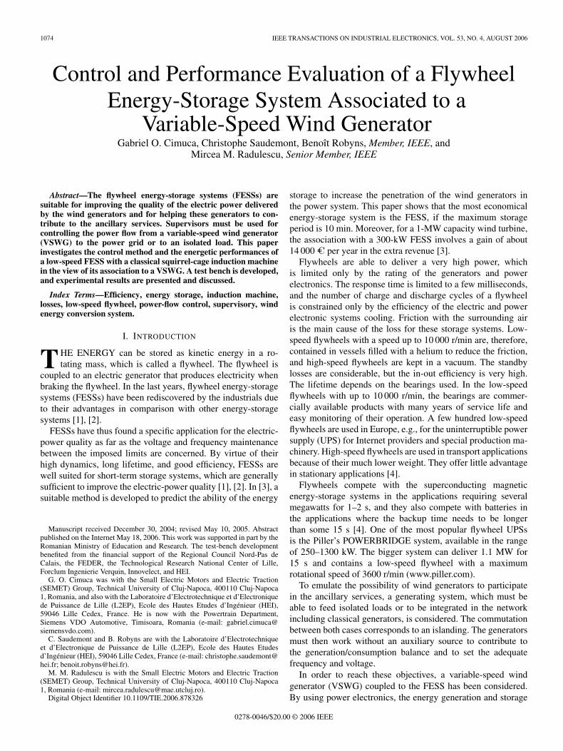
Fig. 1. VSWG–FESS assembly under study.
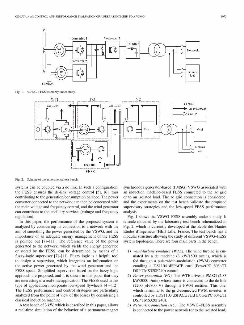
Fig. 2. Scheme of the experimental test bench.
systems can be coupled via a dc link. In such a configuration,the FESS ensures the dc-link voltage control [5], [6], thuscontributing to the generation/consumption balance. The powerconverter connected to the network can then be concerned withthe main voltage and frequency control, and the wind generatorcan contribute to the ancillary services (voltage and frequencyregulation).
In this paper, the performance of the proposed system isanalyzed by considering its connection to a network with theaim of smoothing the power generated by the VSWG, and theimportance of an adequate energy management of the FESSis pointed out [7]–[11]. The reference value of the powergenerated to the network, which yields the energy generatedor stored by the FESS, can be determined by means of afuzzy-logic supervisor [7]–[11]. Fuzzy logic is a helpful toolto design a supervisor, which integrates an information onthe active power generated by the wind generator and theFESS speed. Simplified supervisors based on the fuzzy-logicapproach are proposed, and it is shown in this paper that theyare interesting in a real-time application. The FESSs used in thistype of application incorporate low-speed flywheels [4]–[12].The FESS performance and control strategies are particularlyanalyzed from the point of view of the losses by considering aclassical induction machine.
A test bench of 3 kW, which is described in this paper, allowsa real-time simulation of the behavior of a permanent-magnet
synchronous generator-based (PMSG) VSWG associated withan induction machine-based FESS connected to the ac gridor to an isolated load. The ac grid connection is considered,and the experiments on the test bench validate the proposedsupervisory strategies and the low-speed FESS performanceanalysis.
Fig. 1 shows the VSWG–FESS assembly under a study. Itis scale modeled by the laboratory test bench schematized inFig. 2, which is currently developed at the Ecole des HautesEtudes d’Ingenieur (HEI) Lille, France. The test bench has amodular structure allowing the study of different VSWG–FESSsystem topologies. There are four main parts in the bench.
1) Wind-turbine emulator (WTE). The wind turbine is em-ulated by a dc machine (3 kW/1500 r/min), which isfed through a pulsewidth-modulation (PWM) converterentailing a DS1104 dSPACE card (PowerPC 603e/TIDSP TMS320F240) control.
2) Power generation (PG). The WTE drives a PMSG (2.83kW/3000 r/min) whose stator is connected to the dc link(2200 µF/800 V) through a PWM rectifier. This one,which is similar to the grid-connected PWM inverter, iscontrolled by a DS1103 dSPACE card (PowerPC 604e/TIDSP TMS320F240).
3) Network Connection (NC). The VSWG–FESS assemblyis connected to the power network (or to the isolated load)

1076 IEEE TRANSACTIONS ON INDUSTRIAL ELECTRONICS, VOL. 53, NO. 4, AUGUST 2006
Fig. 3. Photographs of the test bench.
through a PWM inverter, which is controlled always bythe DS1103 dSPACE card.
4) FESS. The squirrel-cage induction machine—IM (3 kW/1500 r/min), which is coupled to a flywheel (0.2 kg · m2),is powered by a DS1104 dSPACE card-controlled PWMconverter.
All the PWM converters have the same structure and areprovided with SEMIKRON insulated gate bipolar transistors(IGBTs) (1200 V/50 A). Control and measurement interfacesbetween converters, dSPACE cards and sensors make the pos-sible configuration changes.
Fig. 3 shows the test-bench pictures and allows identifyingits main components. Converter No. 4 is used for supplying thedc machine.
The developed test bench allows investigations of the grid-connected or isolated load-connected energy generation andstorage systems. Several grid connections can be thus consid-ered with a reference to the filter (L, LC, etc.) used, so thatthe different control strategies accounting for likely unbalancedenergy flows can be implemented.
In the next section, the FESS control strategy, two power-flow supervisors, and the FESS IM control are treated. Experi-mental results are presented in order to validate the theoreticalconcepts. Section III deals with a FESS performance evaluationby determining its losses and efficiency. Related simulation andexperimental results are presented. The design of a fuzzy-logicsupervisor is outlined in Appendix A, and the experimentalFESS main parameters are given in Appendix B.
II. CONTROL OF A FESS ASSOCIATED TO A VSWG
A. Control Strategy for the FESS
The wind generators are considered as negative charges forthe power grid, because they do not consume the electric energybut generate it without participating to the ancillary services. Itis well known that the wind speed is very fluctuant, and by this
Fig. 4. Graphic representation of the FESS control strategy.
reason, the wind generator will deliver a variable electric power.To overcome this drawback, two methods are available, i.e.,
1) acting on the mechanical system, e.g., using the pitch-or stall-controlled wind turbines in order to deliver aconstant power to the wind generator [13] and [14];
2) acting on the electric system, e.g., associating an energy-storage system with the wind generator in order toregulate the electric power delivered into the power grid[5]–[12].
The first method gives acceptable results when connectingthe wind generators at a strong power grid, but if the wind gen-erator supplies a weak grid or an isolated load, the power fluctu-ations can still be questionable. That is the reason for choosingthe second method in the power regulation. An energy buffer isneeded in order to make a good power regulation [5]–[12].
In this paper, the energy buffer consists of a FESS with aclassical squirrel-cage induction machine as is shown in Fig. 1.A PMSG is used as a VSWG.
Fig. 4 gives a graphic explanation of the control principle ofthe FESS. The FESS has two functions: 1) to regulate the dc-link voltage and 2) to regulate the power flow toward the mains.
To regulate the dc-link voltage, a PI voltage controller is usedand gives the value of the power ∆P required for maintainingthis voltage at the reference value VDCref . If Preg is the power

CIMUCA et al.: CONTROL AND PERFORMANCE EVALUATION OF A FESS ASSOCIATED TO A VSWG 1077
Fig. 5. Block diagram of the supervisor.
Fig. 6. Surface of the fuzzy-logic supervisor.
expected from the coupling VSWG–FESS assembly and Pwg,which is the active power generated by the VSWG, the refer-ence value of the active power exchanged between the FESSand the dc-link is determined by
Pref = Preg − Pwg − ∆P. (1)
B. FESS Power-Flow Supervisory
In [7] and [11], a fuzzy logic-based supervisor was proposedto control the FESS in association with the VSWG. The fly-wheel speed has a finite range of variation. The supervisorhas to compute the value of Preg from (1) in order to main-tain the flywheel speed between its limits. The inputs of thesupervisor are the filtered value of the generated power Pwgfand the flywheel speed Ω, respectively. Ideally, the Preg shouldbe identical with the Pwgf , but that means an infinite inertiaof the flywheel in order to hamper the overfulfillment of itsspeed limits. Therefore, the supervisor adapts the Preg valuein function of the Pwgf and the flywheel speed, respectively.The supervisor is schematized in Fig. 5 and fully described inAppendix A.
The fuzzy-logic supervisor was tested by a simulation witha MATLAB/Simulink, and the behavior of the FESS–VSWGsystem was satisfactory [7]. Unfortunately, the implementationof the fuzzy-logic supervisor on the DS 1104 dSPACE cardneeds a very big cycle period (900 µs), which alters the controlof the FESS electric machine. This was the reason for searchinga simplified supervisor in order to reduce the cycle period.
Fig. 6 shows the surface of the fuzzy-logic-supervisor repre-sentation. It can be approximated by the surface of Fig. 7 [11],which is empirically computed by
Preg = 0.63 · Pwgf + 0.52 · Ω − 0.17[p.u.]. (2)
Fig. 7. Surface of the simplified supervisor.
TABLE IPreg VALUES FOR THE CONSTANT-POWER SUPERVISOR
Fig. 8. Surface of the constant-power supervisor.
The parameters of (2) were chosen in order to keep thecorners of the approximated surface in Fig. 7 as closer aspossible to the four external corners of the fuzzy-logic surfaceof Fig. 6. By using this method, the better approximation of thefuzzy-logic surface can be obtained. The supervisor based on(2) was implemented on the DS 1104 dSPACE card. Hence, thecontrol of the FESS can be done during a shorter cycle period(200 µs).
With the simplified supervisor, the value of Preg is alwaysvariable due to the flywheel speed fluctuations. However, Pregis more smoothed than Pwg, but less smoothed than Pwgf .
1078 IEEE TRANSACTIONS ON INDUSTRIAL ELECTRONICS, VOL. 53, NO. 4, AUGUST 2006
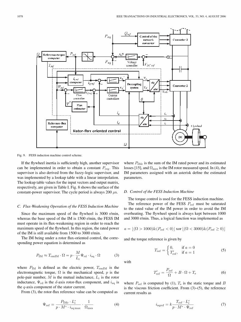
Fig. 9. FESS induction machine control scheme.
If the flywheel inertia is sufficiently high, another supervisorcan be implemented in order to obtain a constant Preg. Thissupervisor is also derived from the fuzzy-logic supervisor, andwas implemented by a lookup table with a linear interpolation.The lookup table values for the input vectors and output matrix,respectively, are given in Table I. Fig. 8 shows the surface of theconstant-power supervisor. The cycle period is always 200 µs.
C. Flux-Weakening Operation of the FESS Induction Machine
Since the maximum speed of the flywheel is 3000 r/min,whereas the base speed of the IM is 1500 r/min, the FESS IMmust operate in its flux-weakening region in order to reach themaximum speed of the flywheel. In this region, the rated powerof the IM is still available from 1500 to 3000 r/min.
The IM being under a rotor flux-oriented control, the corre-sponding power equation is determined as
PIM ≈ TemIM · Ω = p · MLr
Ψrd · isq · Ω (3)
where PIM is defined as the electric power, TemIM is theelectromagnetic torque, Ω is the mechanical speed, p is thepole-pair number, M is the mutual inductance, Lr is the rotorinductance, Ψrd is the d-axis rotor-flux component, and isq isthe q-axis component of the stator current.
From (3), the rotor-flux reference value can be computed as
Ψref =PIMr · L∗
r
p ·M ∗ · isqmax · 1Ωmes
(4)
where PIMr is the sum of the IM rated power and its estimatedlosses [15], and Ωmes is the IM rotor measured speed. In (4), theIM parameters assigned with an asterisk define the estimatedparameters.
D. Control of the FESS Induction Machine
The torque control is used for the FESS induction machine.The reference power of the FESS Pref must be saturated
to the rated value of the IM power in order to avoid the IMoverheating. The flywheel speed is always kept between 1000and 3000 r/min. Thus, a logical function was implemented as
a = (Ω > 1000)&(Pref < 0) xor (Ω < 3000)&(Pref ≥ 0)
and the torque reference is given by
Tref =
0, if a = 0T ′ref , if a = 1 (5)
with
T ′ref =
PrefΩ
+B · Ω + Ts (6)
where Pref is computed by (1), Ts is the static torque and Bis the viscous friction coefficient. From (3)–(5), the referencecurrent results as
isqref = kTref · L∗
r
p ·M ∗ · Ψref(7)

CIMUCA et al.: CONTROL AND PERFORMANCE EVALUATION OF A FESS ASSOCIATED TO A VSWG 1079
Fig. 10. Wind speed.
Fig. 11. Speed of the wind generator, without the FESS.
where k is an experimentally determined coefficient whosevalue depends on the IM’s operation modes, i.e.,
k =
0.95, if Pref ≥ 0 (motor)ΨrefΨr, if Pref < 0 (generator) (8)
where Ψr is the rated value of the IM rotor flux.The control scheme of the FESS induction machine is pre-
sented in Fig. 9. The torque control of the IM gives very goodresults and allows the FESS to control the dc-link voltage andthe power flow from the VSWG to the mains.
E. Experimental Results for the VSWG–FESS Assembly
Experiments were carried out to validate the developed su-pervisors and the control of the dc-link voltage by the FESS.The experiments prove that the FESS can control the dc-linkvoltage and the power flow from the generation system to thepower network or the isolated load.
The FESS can either smooth the power delivered into thepower network or control the power flow in order to deliver aconstant power into an isolated load (or into a weak grid). Theexperiments presented in this paper concern only the networkconnection of the VSWG–FESS assembly without consideringthe isolated-load feeding. As it can be seen in Fig. 9, thenetwork converter can also be controlled to deliver a reactivepower into the network, which is necessary to the VSWG–FESSassembly for contributing to the ancillary services.
Fig. 10 shows the wind speed, which was measured in thenorthern part of France, where a wind farm was installed. Thesewind-speed values were used to control the WTE. Fig. 11 showsthe speed of the VSWG, which is the same with the WTE speed,and Fig. 12 shows the power delivered to the power grid by theVSWG. As it can be shown in Fig. 12, the power grid receivesa variable power.
1) Power smoothing. Figs. 13–18 show how the simpli-fied supervisor operates in order to smooth the electricpower delivered into the network. Fig. 14 shows theregulated power given by the simplified supervisor Preg,
Fig. 12. Power delivered into the power network, without the FESS.
Fig. 13. Speed of the VSWG.
Fig. 14. Regulated power Preg.
Fig. 15. Electric power delivered into the power network.
Fig. 16. Flywheel speed.
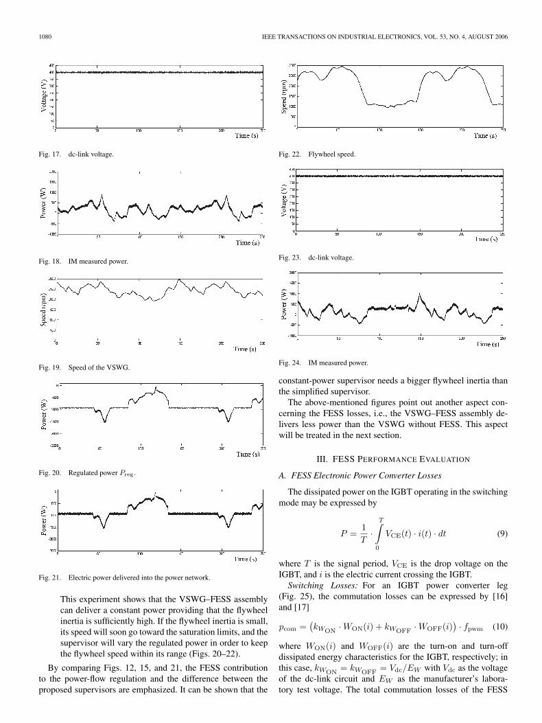
and the network receives a smoothed power (Fig. 15).The regulated power is more smoothed with respect tothe generated power and that involves the flywheel-speedvariations (Fig. 16). The dc-link voltage is well regulatedat 400 V by the FESS (Fig. 17). Fig. 18 shows themeasured power at the IM terminals.
2) Constant-power supervisor. Figs. 19–24 present the ex-perimental results with the constant-power supervisor. Ifthe wind generator supplies a weak grid or an isolatedload, it must be capable to deliver a constant power.
1080 IEEE TRANSACTIONS ON INDUSTRIAL ELECTRONICS, VOL. 53, NO. 4, AUGUST 2006
Fig. 17. dc-link voltage.
Fig. 18. IM measured power.
Fig. 19. Speed of the VSWG.
Fig. 20. Regulated power Preg .
Fig. 21. Electric power delivered into the power network.
This experiment shows that the VSWG–FESS assemblycan deliver a constant power providing that the flywheelinertia is sufficiently high. If the flywheel inertia is small,its speed will soon go toward the saturation limits, and thesupervisor will vary the regulated power in order to keepthe flywheel speed within its range (Figs. 20–22).
By comparing Figs. 12, 15, and 21, the FESS contributionto the power-flow regulation and the difference between theproposed supervisors are emphasized. It can be shown that the
Fig. 22. Flywheel speed.
Fig. 23. dc-link voltage.
Fig. 24. IM measured power.
constant-power supervisor needs a bigger flywheel inertia thanthe simplified supervisor.
The above-mentioned figures point out another aspect con-cerning the FESS losses, i.e., the VSWG–FESS assembly de-livers less power than the VSWG without FESS. This aspectwill be treated in the next section.
III. FESS PERFORMANCE EVALUATION
A. FESS Electronic Power Converter Losses
The dissipated power on the IGBT operating in the switchingmode may be expressed by
P =1T
·T∫0
VCE(t) · i(t) · dt (9)
where T is the signal period, VCE is the drop voltage on theIGBT, and i is the electric current crossing the IGBT.Switching Losses: For an IGBT power converter leg
(Fig. 25), the commutation losses can be expressed by [16]and [17]
pcom =(kWON
·WON(i) + kWOFF·WOFF(i)
) · fpwm (10)
where WON(i) and WOFF(i) are the turn-on and turn-offdissipated energy characteristics for the IGBT, respectively; inthis case, kWON
= kWOFF= Vdc/EW with Vdc as the voltage
of the dc-link circuit and EW as the manufacturer’s labora-tory test voltage. The total commutation losses of the FESS

CIMUCA et al.: CONTROL AND PERFORMANCE EVALUATION OF A FESS ASSOCIATED TO A VSWG 1081
Fig. 25. Structure of a power converter leg.
Fig. 26. Positive half period of the current waveform at the power-converterleg terminal.
three-phase bridge-type power converter are obtained by tre-bling pcom of (10).Conduction Losses: Fig. 26 shows the electric current at
one terminal of the power converter for a positive half period;the IGBT conduction periods TIGBT and of the diode TD arepresented for a PWM period TPWM. If the PWM frequencyis sufficiently high, it can be considered that for an electricalperiod, the cyclic ratio for a power converter leg is
ρ =12
+r · sin(θ + ϕ)
2=TIGBTTpwm
= TIGBT · fpwm (11)
where fpwm = 1/Tpwm, r denotes the modulation depth and ϕas the power factor. Some values for ρ are given in Fig. 27.
It should be noted that the dead time of the power converteris not considered in this study.
Therefore, the conduction periods of the IGBTs and diodesduring a PWM period are, respectively,
TIGBT =ρ
fpwm=
(12
+r · sin(θ + ϕ)
2
)· Tpwm (12a)
TD =1 − ρ
fpwm=
(12− r · sin(θ + ϕ)
2
)· Tpwm. (12b)
A sinusoidal shape of the current has been assumed byneglecting its overlapped waves, i.e., i = |Ik| sin θ [18]. More-over, the current is a supposed constant during the PWM period,and only the positive half period of the current is considered
Fig. 27. Waveforms of the voltage u, current i, and power P .
for the losses computation (for the second half period of thecurrent, the losses being the same).
The dissipated energy in the IGBT during one PWM periodand for an angle θ is given by
ETR = VCE · |Ik| sin θ ·(
12
+r · sin(θ + ϕ)
2
)· Tpwm (13)
where VCE is the voltage drop on the IGBT in the switch-on mode. The average dissipated power in the IGBT for anangle θ is
PTR = VCE · |Ik| sin θ ·(
12
+r · sin(θ + ϕ)
2
). (14)
Fig. 27 shows that the power has a double pulsation ascompared to the voltage or the current. Therefore, the averagedissipated power in the IGBT can be written as
PIGBT = VCE · |Ik| ·(
1π
+r · cosϕ
4
). (15)
In the same way, the diode conduction losses can bewritten as
PD = VD · |Ik| ·(
1π− r · cosϕ
4
)(16)
where VD is the voltage drop on the diode. Equations (15) and(16) determine the conduction losses for one leg of the powerelectronic converter. Hence, the total conduction losses of theFESS power converter are given by (17):
pcond = 3 · (PIGBT + PD) = 3 · |Ik|
·(VCE + VD
π+ r · cosϕ · VCE − VD
4
). (17)
By summing the commutation and conduction losses givenby (10) and (17), respectively, one obtains the total losses of theFESS power converter. The characteristics of the SKM 50 GB

1082 IEEE TRANSACTIONS ON INDUSTRIAL ELECTRONICS, VOL. 53, NO. 4, AUGUST 2006
Fig. 28. Equivalent diagram of the IM.
123 D IGBT module, which are provided by SEMIKRON, havebeen used in the simulation of the FESS power converter with aPWM frequency set at 8 kHz. This frequency has been chosenbecause of the dSPACE card.
B. FESS Electromechanical Losses
Stator copper losses of the IM are computed by using thestator resistance Rs and the park components of the statorcurrent
pJS = Rs · (i2sd + i2sq). (18)
Rotor copper losses for the IM can be written as the productof the IM electric power PIM and the slip s
pJR = s · PIM = s · (vsd · isd + vsq · isq). (19)
Iron losses are determined from the IM equivalent diagramof Fig. 28.
pFe = 3 · (Us · cosϕ−Rs · Is)2 + (Us · sinϕ)2
Rµ. (20)
It should be noted that (20) calculates the IM iron losses fora sinusoidal regime by neglecting the PWM losses.
Friction losses are determined as
pf = Ω · (Ts + Ω ·B). (21)
C. Simulation Results and Efficiency Estimation
According to the above established FESS losses equations,the simulations were performed in the MATLAB/Simulinkenvironment in order to determine the IM-based FESS effi-ciency. The scheme from Fig. 1 was simplified like it canbe shown in Fig. 29. With this scheme, the energy is takenfrom the power network to accelerate the flywheel, and thenthe flywheel is braked and returns its energy to the powernetwork. Accordingly, the FESS efficiency can be determinedeither for one operating (charging or discharging) mode or fora charge/discharge cycle (CDC).
To determine the FESS efficiency for a CDC, the simplestway is to estimate the energy by integrating the measuredpower. Therefore, the FESS efficiency is
ηFESS =∣∣∣∣Ed
Es
∣∣∣∣ · 100 (22)
where Es and Ed are the energy stored/delivered in/from theflywheel, respectively, both considered for one CDC.
Fig. 29. Block scheme of the system used to determine the FESS efficiency.
The FESS electric-power converter efficiency obtained fromsimulations in the MATLAB/Simulink was 97.5%. It should benoted that this efficiency concerns only the Converter 2 fromFig. 29. During the experiments, the measure of the current inthe dc link was very difficult because of the very fast variationsof the current. On the other hand, it was simpler to measurethe power at the alternative sides of the converters 2 and 3,respectively, and to determine the global efficiency of the dc-link power converter, i.e., coupling the two converters andthe dc link. Thus, the global efficiency of the dc-link powerconverter, which is determined by simulations, was about 95%.
For the IM-based FESS, the simulation results revealed anIM efficiency of about 90%. The efficiency for one CDC of theFESS was 77% at the dc-link side of the Converter 2 and 73%at the network side of the Converter 3.
D. Experimental Results and FESS Efficiency Determination
The scheme of Fig. 29 was implemented on the test bench,and experiments were carried out in order to determine theFESS efficiency.
By considering the energy at the IM terminals, the efficiencyof the IM plus flywheel can be determined. The FESS efficiencyis determined from the energies at the network-side terminals ofthe Converter 3 from Fig. 29. By comparing the energy at thenetwork side and the energy at the IM terminals, the efficiencyof the dc-link power converter can be determined [15].
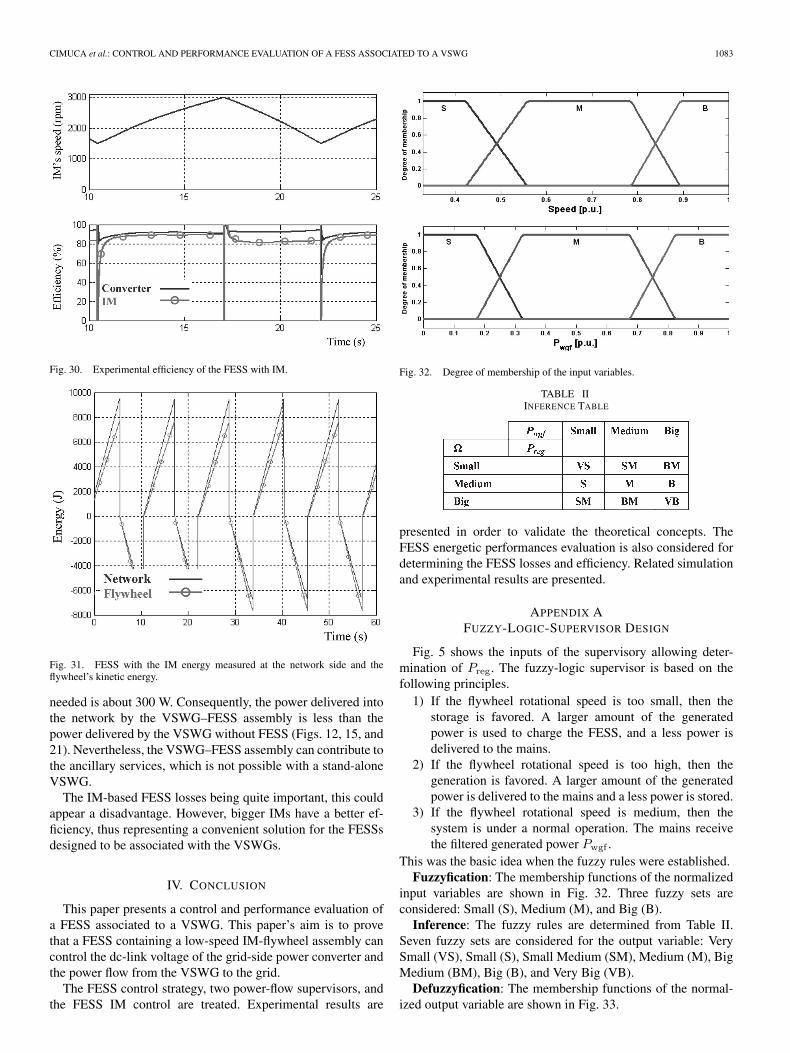
Fig. 30 presents the experimental results of the IM-basedFESS. It can be shown that the IM efficiency was 88% inthe rated-load (charging) mode and 81% in the generator (dis-charging) mode. The resulted dc-link power converter globalefficiency was 91% in charging and to 92% in dischargingoperation, respectively.
Fig. 31 shows the variations of the FESS energy and theflywheel energy for some CDCs of the IM-based FESS. Thepositive values of the energy are for the charging operationmode. This experiment allows the determination of the FESSefficiency for one CDC (or only for one operating mode of theFESS). Therefore, the experimentally obtained efficiency of theIM-based FESS for one CDC was about 71% (at the networkside of the Converter 3).
Figs. 18 and 24 show that the maximum IM measured poweris about 1 kW, but this is only for some seconds. The IM averagepower is around 0.5 kW. Hence, an IM of 0.75 kW would besufficient for the experimental FESS.
As the rated power of the IM under study is 3 kW, thisone will always operate under its rated power. This involvesa poor efficiency of the IM. Only for magnetizing it, the power
CIMUCA et al.: CONTROL AND PERFORMANCE EVALUATION OF A FESS ASSOCIATED TO A VSWG 1083
Fig. 30. Experimental efficiency of the FESS with IM.
Fig. 31. FESS with the IM energy measured at the network side and theflywheel’s kinetic energy.
needed is about 300 W. Consequently, the power delivered intothe network by the VSWG–FESS assembly is less than thepower delivered by the VSWG without FESS (Figs. 12, 15, and21). Nevertheless, the VSWG–FESS assembly can contribute tothe ancillary services, which is not possible with a stand-aloneVSWG.
The IM-based FESS losses being quite important, this couldappear a disadvantage. However, bigger IMs have a better ef-ficiency, thus representing a convenient solution for the FESSsdesigned to be associated with the VSWGs.
IV. CONCLUSION
This paper presents a control and performance evaluation ofa FESS associated to a VSWG. This paper’s aim is to provethat a FESS containing a low-speed IM-flywheel assembly cancontrol the dc-link voltage of the grid-side power converter andthe power flow from the VSWG to the grid.
The FESS control strategy, two power-flow supervisors, andthe FESS IM control are treated. Experimental results are
Fig. 32. Degree of membership of the input variables.
TABLE IIINFERENCE TABLE
presented in order to validate the theoretical concepts. TheFESS energetic performances evaluation is also considered fordetermining the FESS losses and efficiency. Related simulationand experimental results are presented.
APPENDIX AFUZZY-LOGIC-SUPERVISOR DESIGN
Fig. 5 shows the inputs of the supervisory allowing deter-mination of Preg. The fuzzy-logic supervisor is based on thefollowing principles.
1) If the flywheel rotational speed is too small, then thestorage is favored. A larger amount of the generatedpower is used to charge the FESS, and a less power isdelivered to the mains.
2) If the flywheel rotational speed is too high, then thegeneration is favored. A larger amount of the generatedpower is delivered to the mains and a less power is stored.
3) If the flywheel rotational speed is medium, then thesystem is under a normal operation. The mains receivethe filtered generated power Pwgf .
This was the basic idea when the fuzzy rules were established.Fuzzyfication: The membership functions of the normalized
input variables are shown in Fig. 32. Three fuzzy sets areconsidered: Small (S), Medium (M), and Big (B).
Inference: The fuzzy rules are determined from Table II.Seven fuzzy sets are considered for the output variable: VerySmall (VS), Small (S), Small Medium (SM), Medium (M), BigMedium (BM), Big (B), and Very Big (VB).
Defuzzyfication: The membership functions of the normal-ized output variable are shown in Fig. 33.

1084 IEEE TRANSACTIONS ON INDUSTRIAL ELECTRONICS, VOL. 53, NO. 4, AUGUST 2006
Fig. 33. Degree of membership of the output variable.
APPENDIX BFESS MAIN PARAMETERS
IM-plus-flywheel parametersNumber of poles 2p = 4.Stator resistance Rs = 0.76 Ω.Rotor resistance Rr = 0.76 Ω.Core-loss resistance Rµ = 293.3 Ω.Magnetizing inductance M = 77.67 mH.Leakage inductance Lσ = 7.30 mH.Stator inductance Ls = 81.32 mH.Rotor inductance Lr = 81.32 mH.Total leakage factor σ = 0.071.Rated current I = 10.9 A.FESS inertia J = 0.2085 kg · m2.Viscous friction coefficient B = 0.0011 N · m · s · rad−1.
dc-link parametersCapacity C = 2200 µF.Maximal voltage Vdcmax = 800 V.
Power converter parametersAll the power converters are provided by SEMIKRON and
are composed from a SKD 51/14 rectifier module, three SKM50 GB 123 D and one SKM 50 GAL 123 D IGBT moduleswhose parameters are fully given at http://www.semikron.com.
REFERENCES
[1] R. Hebner, J. Beno, and A. Walls, “Flywheel batteries come aroundagain,” IEEE Spectr., vol. 39, no. 4, pp. 46–51, Apr. 2002.
[2] R. G. Lawrence, K. L. Craven, and G. D. Nichols, “Flywheel UPS,” IEEEInd. Appl. Mag., vol. 9, no. 3, pp. 44–50, May/Jun. 2003.
[3] J. P. Barton and D. G. Infield, “Energy storage and its use with intermit-tent renewable energy,” IEEE Trans. Energy Convers., vol. 19, no. 2,pp. 441–448, Jun. 2004.
[4] EUR 19978 Brochure: “Energy Storage—A Key Technology for Decen-tralized Power, Power Quality and Clean Transport”, 2001, Luxembourg:Office for Official Publications of the European Communities. [Online].Available: www.cordis.lu/eesd/src/lib_misc.htm
[5] R. Cardenas, R. Pena, G. Asher, and J. Clare, “Control strategies for en-hanced power smoothing in wind energy systems using a flywheel drivenby a vector-controlled induction machine,” IEEE Trans. Ind. Electron.,vol. 48, no. 3, pp. 625–635, Jun. 2001.
[6] R. Cardenas, R. Pena, G. Asher, J. Clare, and R. Blasco-Giménez,“Control strategies for power smoothing using a flywheel driven by asensorless vector-controlled induction machine operating in a wide speedrange,” IEEE Trans. Ind. Electron., vol. 51, no. 3, pp. 603–614, Jun. 2004.
[7] L. Leclercq, B. Robyns, and J.-M. Grave, “Control based on fuzzy logicof a flywheel energy storage system associated with wind and dieselgenerators,” Math. Comput. Simul., vol. 63, no. 3–5, pp. 271–280, 2003.
[8] L. Leclercq, C. Saudemont, B. Robyns, G. Cimuca, and M. M. Radulescu,“Flywheel energy storage system to improve the integration of windgenerators into a network,” Electromotion, vol. 10, no. 4, pp. 647–652,2003.
[9] L. Leclercq, A. Kamagate, B. Robyns, and J.-M. Grave, “Modellingand simulation of a flywheel energy storage system associated with wind
and diesel generators,” in Proc. ICEM, Bruges, Belgium, Aug. 2002,pp. 25–28.
[10] L. Leclercq, A. Ansel, and B. Robyns, “Autonomous high power variablespeed wind generator system,” in Proc. EPE, Toulouse, France, Sep. 2003,CD-ROM.
[11] L. Leclercq, B. Robyns, and J. M. Grave, “Fuzzy logic based supervisorof a flywheel energy storage system associated with wind and dieselgenerators,” in Proc. 8th Int. Conf. Optimization Electr. and Electron.Equipments—OPTIM, Brasov, Romania, May 2002, vol. 2, pp. 441–446.
[12] F. Hardan, J. A. M. Bleijs, R. Jones, and P. Bromley, “Bi-directionalpower control for flywheel energy storage system with vector-controlledinduction machine drive,” in Proc. 7th Int. Conf. Power Electron. VariableSpeed Drives (IEE Conf. Publ. No. 456), Sep. 21–23, 1998, pp. 477–482.
[13] Danish Wind Industry Association. [Online]. Available: http://www.windpower.org/en/tour/wtrb/powerreg.htm
[14] S. Hurtado, G. Gostales, A. de Lara, N. Moreno, J. M. Carrasco,E. Galvan, J. A. Sanchez, and L. G. Franquelo, “A new power stabilizationcontrol system based on making use of mechanical inertia of a variable-speed wind-turbine for stand-alone wind-diesel applications,” in Proc.IEEE IECON 2002, Seville, Spain, Oct. 2002, pp. 3326–3331.
[15] G. Cimuca, M. M. Radulescu, C. Saudemont, and B. Robyns, “Perfor-mance analysis of an induction machine-based flywheel energy storagesystem associated to a variable-speed wind generator,” in Proc. 9th Int.Conf. Optimization Electr. and Electron. Equipments—OPTIM, Brasov,Romania, May 2004, vol. 2, pp. 319–326.
[16] T. Brückner and S. Bernet, “Investigation of a high-power three-levelquasi-resonant dc-link voltage-source inverter,” IEEE Trans. Ind. Appl.,vol. 37, no. 2, pp. 619–627, Mar./Apr. 2001.
[17] P. Bastiani, “Stratégies de commande minimisant les pertes d’un ensembleconvertisseur-machine alternative: Application à la traction électrique,”Ph.D. dissertation, Inst. Nat. des Sci. Appliquées de Lyon, Lyon, France,2001.
[18] C. Rivas and A. Rufer, “Comparaison des pertes des convertisseurspour systèmes de production d’énergie électrique à partir d’une pile àcombustible, Actes de 8ème Colloque,” in Proc. EPF, Lille, France,Nov. 29–Dec. 1, 2000, pp. 239–243.
Gabriel O. Cimuca received the M.S. degree fromthe Electrical Engineering Faculty, Technical Uni-versity of Cluj-Napoca, Cluj-Napoca, Romania, in2001, and the Ph.D. degree jointly from the Tech-nical University of Cluj-Napoca and the Ecole Na-tionale Superieure d’Arts et Metiers de Lille, France,in 2005, both in electrical engineering.
Between November 2001 and October 2005, hewas a Ph.D. student in the Electrical EngineeringFaculty, Technical University of Cluj-Napoca, Cluj-Napoca, Romania, and at Ecole Nationale Superieure
d’Arts et Metiers (ENSAM) de Lille, France. He worked within the Laboratoired’Electrotechnique et Electronique de Puissance (L2EP) de Lille, Lille, France,and was engaged in theoretical and experimental research on a flywheel energystorage system to be associated with a variable-speed wind generator. SinceMarch 2006, he has been with the Powertrain Department, Siemens VDOAutomotive, Timisoara, Romania. He is author or coauthor of 17 technicalpapers and reports.
Dr. Cimuca received the 3rd and 2nd Prize Awards at the Romanian High-School Competition in Electrotechnics in 1995 and 1996, respectively.
Christophe Saudemont received the Ph.D. degreein electrical engineering from the Science and Tech-nology University of Lille, Lille, France, in 1999.
Since 2001, he has been with the Depart-ment of Electrical Engineering, Ecole des HautesEtudes d’Ingenieur, Lille, France. Since 2002, hehas also been a Researcher with the Laboratoired’Electrotechnique et Electronique de Puissance deLille, Lille, France. His research interests includerenewable energies, decentralized electric energyproduction, and integration of dispersed renewable
energy sources.Dr. Saudemont is a member of the Société française des Electriciens et des
Electroniciens.

CIMUCA et al.: CONTROL AND PERFORMANCE EVALUATION OF A FESS ASSOCIATED TO A VSWG 1085
Benoît Robyns (M’96) was born in Brussels, Bel-gium, in 1963. He received the Ingénieur Civil Elec-tricien and Docteur en Sciences Appliquées degreesfrom the Université Catholique de Louvain, Louvain-la-Neuve, Belgium, in 1987 and 1993, respectively,and the Habilitation á Diriger des Recherches degreefrom the Université des Sciences et Technologies deLille, Lille, France, in 2000.
From 1988 to 1995, he was with the Laboratoryof Electrotechnics and Instrumentation, Faculty ofApplied Sciences, Catholic University of Louvain, as
an Assistant. Since 1995, he has been with the Department of Electrotechnics,Ecole des Hautes Etudes d’Ingénieur, Lille, France, where he is currentlythe Department Head. Since 1998, he has also been with the Laboratory ofElectrotechnics and Power Electronics of Lille, Lille, France, as a Researcher,where he is currently the Head of the Electrical Network and Energetic Systemsresearch team. He is the author and coauthor of more than 100 papers inthe fields of digital control of electrical machines, renewable energies, anddistributed generation.
Prof. Robyns is a member of the Société Franse des Electriciens et desElectroniciens, the Société Royale Belge des Electriciens, and the EuropeanPower Electronics Association.
Mircea M. Radulescu (M’94–SM’99) was born inCluj-Napoca, Romania, on September 4, 1954. Hereceived the Dipl.-Ing. degree (with honors) from theTechnical University of Cluj-Napoca, Cluj-Napoca,Romania, in 1978 and the Dr.-Ing. degree fromthe Polytechnic University of Timisoara, Timisoara,Romania, in 1993, both in electrical engineering.
In 1983, he joined the Faculty of Electrical Engi-neering, Technical University of Cluj-Napoca, wherehe is currently a Full Professor in the Department ofElectric Machines and the Head of the Small Electric
Motors and Electric Traction Group. He was an Invited Research Associate withthe Laboratoire d’Electromécanique et de Machines Electriques, Ecole Poly-technique Fédérale de Lausanne, Switzerland, during 1990-1991 and with theLaboratoire d’Electrotechnique de Grenoble, Institut National Polytechniquede Grenoble, France, during 1992-1993. He was an Invited Professor withHelsinki University of Technology, Finland, in 1997; Rheinisch-WestfälischeTechnische Hochschule Aachen, Germany, in 1999; the University of Akron,OH, in 1999 and 2001; the Université ‘Pierre et Marie Curie’ (Paris VI), France,in 2002; and the Université de Picardie ‘Jules Verne’ Amiens, France, in 2003.He is the author and coauthor of ten scientific monographs, multiauthor books,and textbooks, and of more than 100 published scientific papers in refereedtechnical journals and international conference and symposium proceedings.His teaching and research activities include computer-aided design of electro-mechanical devices; field analysis of electromagnetic structures; design andcontrol of small electric motors; actuators and mechatronic drives; design,control, and electromagnetic compatibility of electric traction systems; andferrohydrodynamics.
Prof. Radulescu is a Foundation Member of the Romanian Association ofSmall Electric Machines Builders, an Associate Editor of the internationalscientific quarterly ELECTROMOTION, and a Member of the InternationalSteering Committee of several conferences and symposia in the field of electricmotor drives and electric traction. His biography is listed in Who’s Who in theWorld (Editions 1997–1999) and Who’s Who in Romania (Edition 2002).