control and transfer switches . com . …...control and transfer switches multi-stage -versatile...
TRANSCRIPT

Control and Transfer Switches Multi-stage - versatile - reliable
The SBM Switch
-rotary, cam-operated, compact - for panel mounting only. Two electrica l ly separate and mechan ica l ly independent contacts per stage. These smal l , versati le switches mount c lose and wire easi ly on you r switchboard. Common types are warehouse stock.
The SB-1 Switch
-rotary, cam-operated , sl ightly larger than the SBM switch and capable of more design flex ib i l ity . Can be independently mounted and housed - Navy approved i n relevant appl ications. Many common types warehou sed .
The SB-9 Switch
-a heavier-duty switch than the SB-1 -for appl ications requir ing u nusua l ly high nu mbers of repetitive operations, but otherwise sim i lar in optional features and design capabi l ity.
The SB-10 Switch
-in add i tion to the rotary operation l ike the SB-1 switch, the SB-1 0 i s capable of opening and closing contacts with a lateral push or pu l l of the handle.
Application Information GET-6169
Prices- Handbook Sect. 7151
Instruction Book - GE H-2038
Renewal Parts- GEF-4167
Descriptive Literature- GEA-4746
Application Information GET-6169
Prices- Handbook Sect. 7151
Instruction Book - GE H-908
Renewal Parts- GE·F-2357
Descriptive Literature- GEA-4746
Application Information GET-6169
Prices- Handbook Sect. 7151
Instruction Book- GET-908
Renewal Parts- GEF-3481
Descriptive Literature- GEA-4746
Application Information GET-6169
Prices- Handbook Sect. 7151
Instruction Book- GEH-908
Renewal Parts- GEF-3482
Descriptive Literature- GEA-4746
0
0
0
www . El
ectric
alPar
tMan
uals
. com
www . El
ectric
alPar
tMan
uals
. com

This bul letin supplements its companion, G EA-4746G, to fu rn ish application and ordering information on b o t h s t a n d ard and non-standard contro l and transfer switches manufactured by General E lectric.
Many common appl ications, such as c i rcu i t breaker control , ammeter transfer, and the l i ke, occur again and aga in , and several standard circu its are i l l ustrated for each. Select one wh ich appl ies, and order the switch by number only . If the standard switch is satisfactory except for some minor exception, specify the exception along with the standard catalog n umber.
Introduction
If a standard m odel is not avai lable, fo l low the ordering instructions given in th is publ ication to specify exactly the functions you need. Use one of the fol l owing forms:
Form G E D-3933 - for SBM switches only.
Form G E D-3934 - for SB-1 , -9, - 1 0 switches.
Part 1 -Standard features. Part 2 - Optional features.
Pads of these forms are available to customers of the General Electric Co.
Contents
Cam Action and Li mitations (SBM, SB- 1 , -9, - 1 0)
Overlapping Contacts (SBM, SB- 1 , -9, - 1 0)
Removable Handles (SBM, SB- 1 , -9)
Temperature-meter Switches (SB- 1 )
Special Switch Outl ines . . . . . . .
Contact Diagrams for SBM Switches
Contact Diagrams for SB-1 Switches
Ordering Guide for SBM Switches .
Ordering Gu ide for SB- 1 , -9 , -1 0 Switches
Form G E D-3933, Specification Form , Type SBM Switches
Form G E D-3934, Part 1 . Specification Form, SB- 1 Switches, Standard Features
Form G E D-3934, Part 2. Specification Form, SB-1 Switches, Special Features
Field Modification Instructions for the Type SBM Control Switch
Nomenclature Guide, Type SB- 1 or SB-9 Switches . . . . . . . . .
Copyright © 1979, General Electric Company.
through their local sales office. Where stock is temporar i ly exhausted , copies may be made of the forms printed at the bac� of th is booklet.
Please note that this bul letin should be used with G EA-4746G , which contains descriptive information. Note also that all the earl ier versions, GEA-4746-A through -F, conta ined combinations of the materia l now revised and d ivided between G EA-4746 and GET-6 1 69. If you have been using a copy of one of the earl ier issues for reference, p lease obtain copies of the latest bu l letins.
Page
4
6
8
1 0
1 1
13
27
44
47
53
54
55
56
58
3 www . El
ectric
alPar
tMan
uals
. com
www . El
ectric
alPar
tMan
uals
. com

4
. Cam Action and Limitations
Fig. 1. Operating cam for SB-1, -9, and-10switches
FRONT VIEW, HANDLE IN 120'CLOCK POSITION
"c"OR CLOSING CAM FOR NQI CONTACT NOT SHOWN
Fig. 2. Composite vie w of contacts and cams
Fig. 3. Individual arrangements of cams in Fig. 2
CONT ACTS POSIT ION H AN DLE END 3 2
0-H-0-H-0 I I X
1 2 X X
Fig. 4. Contac t arrangement, back vie w
{BACK) VIEW
I
The operating cam of SB-1, -9, and - 1 0 switches is based on a 3 0-degree cut to each side of the center (F ig. 1) . A standard-profile cam w i l l fu l ly open or close a contact in 30 degrees, making or break ing 15 degrees from the fu l ly open or fu l ly c losed position. �
Fig. 2 is a composite view of contacts and cams assemb led on a stage of a switch. This figure shows that odd-numbered contacts are on the right side of the switch (viewed from the front ) , and are closed by the "C" cam . Even-numbered contacts are on the left side, and are closed by action of the "A" cam . Both contacts are opened by the "B" cam .
F ig . 4 is the contact diagram for � Fig. 2, with F ig. 3 showing the ind ividual arrangement of cams.
O n e cam l imitation must be considered when the switch rotates 18 0 degrees or more. R eferr ing to F ig . 3 , you see that when cam B is rotated 18 0 degrees, the sam e relationship occurs between the periphery of Cam B and the contact mechanism of Con-tact No. 1 as occu rred between the periphery and contact mechanism of Contact No . 2 before rotation; there-fore, whatever happens to one contact at any point in the switch rotation must happen to its companion contact in the same stage when the switch is rotated 180 degrees. Fig. 5 shows the #fl'i· diagram of an unworkab le and a correct arrangement.
When contacts on the same stage cannot be arranged to avoid this 18 0- d eg r ee cam l im itation, one contact per stage is used (See F ig. 6) . 0 n five-position switches, 37-1/2 degrees can be used instead of 45 degrees, to avoid this limitation.
SLIP CAMS
S lip cams increase the f lex ibi l ity of the switch. They al low a contact to be closed in the N O R MA L position after returning from either the CW or CCW position, and also to be open in the N O R MA L position after return ing from the opposite d i rection. This action is accompl ished by al lowing the cam to s l ip 45 degrees as shown in Fig. 7. Once the shaft actuates the cam , the shaft w i l l then s l ip 45 degrees in the opposite d irection without actuating the cam.
This type of action is common ly used for circuit-breaker control appl i cations. F ig. 8 shows a breaker control switch, M odel 16SB 1 82, which has sl ip action on Contacts 7 and 8 . With this s l ip action, there are some l i mitations. Three of these l imitations and how to avoid them are shown in Fig. 9. Limitation No. 1 does not apply to the SBM switch because of the independent cams for each contact.
www . El
ectric
alPar
tMan
uals
. com
www . El
ectric
alPar
tMan
uals
. com

Can� Action and Lin�itations (Cont"d.)
INCORRECT CORRECT CONTACTS POSITIONS (BACK VIEW) CONTACTS POSITIONS (BACK VIEW) I
HANDLE END 8 7 6 5 4 3 2 I HANDLE END 8 7 6 5 4 3 2 I * I 2 o-H-o o-H-o 3 4 o-H-o o-H--o 5 6 o-lkJ o-H-o 7 8 011-0 o-H·-o
I 2 3 4 5 6 7 8 X
X X
X X
X X
X
I 2 o-��-o o-1 ro 3 4 o-11-o e>-i f-o 5 6 o-11-0 o-1 ro 7 8 o-1 kJ o-1 1-0
I X 2 X 3 X 4 X 5 X 6 X 7 X 8 X
Fig. 5. Diagram of unworkable and correct arrangement
I CONTACTS POSITIONS (BACK VIEW
* 7 3
4 5
ESCUTCHEON (FRONT VIE W )
HANDLE END
C>-1�
1--o-11-o
o-1�
ro-11-o
I
4 5
8
8 7 6 5 4 3 X X
X X X X
X X X Fig. 6. Contact arrangement to meet cam limitations
2 I X
X
7 3
4 5
ESCUTCHEON (FRONT VIEW )
P O S I T IONS CO NTACTS
HANDLE END I 2 o-11-o rro ��14 o-1 1-0 5
o-1 '""' '"' J l �I l� 8 o-1 o-11-0
I 2 3 4 5
7 8
Norm Norm Close otter otter Trip
close trip
X X
X X X
X X
X X X X
Fig. 7. Diagram showing 45-degree slip action of cam Fig. 8. Breaker con trol switch model 16SB 1 82
( I NCORRECTl (INCORRECT) ( INCORRECT)
I 2 L I o-H-o o-11-0 1 2
2
(CORRECT) 2
I I o-lf-0---1 4
�� 4 L IMITA TI ON NO. I
2N IN I X X
X X
2N IN I X X
X X ( SB-1, 9 8 10 )
limitation No.1 (SB-1, -9 & -10)
SLIP
STANDARD
3 3N I 2 II o-!1-o o-li-o 12
(CORRECT l
I 2 ?-H--o o-H-<j 3 4 >11-0 01rc
L IMITATION NO.2
3 3N I 2 3 X 4 X
2N 2 I X X X X
2N 2 I X X X X X X X X X X
(S B M , S B -1 , 9 8 10) limitation No.2 ( SBM,SB1, -9 & -10)
I 2 II o-H-o o-H-0 12
2
( CORRECT) 2
I 2 I
CjH 1-0 o-t 1-0 2
� 4 3 f--0 o-H·-< 4
L IMITA TION NO.3
2N IN I X X
2N IN I X X X X
X X X X
( SBM, SB-1, 9810) limitation No.3 (SBM, SB-1, -9 & -10)
A slip contact and standard contact cannot be on the same stage, as shown in the top diagram.
A stage must be added and contacts split up, as shown in the bottom diagram, one contact per stage. (Does not apply to SBM)
On a 4-position pull-to-lock switch tht slip contact cannot be closed in the 2N and 2 positions (As shown in .the top diagram) without closing in position 1. To accomplish this a stage is added, and the contacts are connect in series as shown in the bottom diagram.
A contact cannot be closed in the normal after position without also closing in the position itself, as shown in the top diagram. To accomplish this, a stage must be added and the contacts set up as shown in the bottom diagram, with the contacts placed in series by jumpers. Jumpers required are shipped loose with the switch.
Fig. 9. Slip-cam limitations 5
www . El
ectric
alPar
tMan
uals
. com
www . El
ectric
alPar
tMan
uals
. com

GENERA L
Contacts o n Type S B switches are n o r ma l l y non-overlapping (breakb e f o r e - ma k e ) . This sequence i s i l l u strated in F i g . 1 0 wh ich shows that Contact No. 1 open s before Contact No. 2 closes, when turn ing from Position 1 to Position 2 . Another normal function i s i l l u strated by Contact No. 3, which i s shown closed in two adjacent posit ions (Positions 2 and 3) . When switch ing between these positions, the contact wi l l always remain c losed. There are some circu its where this action is not desired, such as switching current transformers to an ammeter. H ere, the contacts must o v e r l a p ( ma k e - b efo r e-break ) to prevent damaging the meter.
SBM SWITCH
To get this overlapping action on the contacts, 90 degrees between po s 1 t1ons is required . F igure 1 1 i l l ustrates an ammeter switch ( s imi lar to M odel 1 0AA009) with overlapping contacts. The overlapping action takes place in the intermediate positions (Posit ions 2, 4, 6, and 8) . The inter-
Overlapping Contacts
mediate position is identified by an "X" i n the block above this position i n the operating requ irement table. Contacts 1 and 2 are shown overlapping in the intermed iate Posit ions 4 and 6. Contact 2 i s shown mak ing in intermediate Position 4 before Contact 1 breaks, when go ing from Posit ion 3 ( O F F ) to Position 5 (PHASE 1 ) , and Contact 1 wil l make before Contact 2 breaks, when go ing from Position 5 to Posit ion 7.
F igure 1 2 i l l ustrates an ammeter switch for three independent current t r a n sf o r me r s ( similar to Model 1 0AA0 1 3 ) . This switch a l so has overlapping contacts and intermed iates at Positions 2, 4, 6, and 8; however, the overlapping action takes place between the intermed iate position and the actual posit ion . The "X" on th e l ine between the positions of the contacts identifies this action. When turning from Position 5 (PHASE I) to Position 7 (PHASE II), Contact 1 makes before Contacts 2 and 3 break. Also, Contact 2 and 3 break before Contacts 4 and 5 make, and Contacts 4 and 5 make before Contact 6 breaks. All this action takes place with in the 90
degrees between positions, by use of a specia l cam.
SB-1, -9, AND -10 SWITCHES
Basica l ly, the overlapping action i s the same as with the SBM switch, but it i s not l imited to posit ions wh ich are 90-degrees apart.
To get a make-before-break action, as shown in F ig . 1 3, a minimu m of 37% degrees between positions is requi red. To get a make-before-break as shown in F ig . 1 4 , a min i mu m of 60 degrees is requ i red . The flexibi l ity of the SB- 1 , -9, and - 1 0 switch a l lows the combination of 37% degrees and 60 degrees in the same switch to g ive you an ammeter switch which reads as many as six, independent, current transformers with either 1 or 2 O F F 's ( see F ig . 1 5) .
A specia l contact sequence wh ich requ i res a contact to close in adjacent positions, but to open momentari ly between them, i s shown by Contact 1 in F igure 1 6 . A min imum of 60 degrees between positions i s requ i red . When less than 60 degrees is requ i red , use two contacts in paral lel , as shown in F ig. 1 7.
CONTACTS POSITIONS F1g. 1 0. Typical non-overlapping HANDLE END 3 2 I (break-before-make) sequence
I 2 I X o-if-o o-if-o 2 X
�1-o 3 X X
INTER. POSITION
�711d51<3f<. I AMME TER
OFF
2
CONTACTS ODD EVEN
o-U--o o-H--o
�1--o �1--o
�1--o o-H--o
�1--o o-H-o
o-11--o o-11--o
8 I lx: 2 3 4 5 6 .X 7 X 8 9
Fig. 12. Overlapping contacts for SBM ammeter-type switch, with three independent circuits
POSITIONS 7 6 5 4 3 2 I X )( X X ht• rv
lo<:��o kX!, kx
)( ' X pc; tX
�-� be lfx IQV pc; �x; IOc �Xl�-
AMMETER OFF
2
AMME TER 2 3
INTER. POSITI O N *7*5*3*1 CONTACTS POSITIONS
ODD EVEN 8 7 6 5 4 3 2 I I X X X X X X X
o-j f-o o-j 1-o 2 X X X
<>-l 1-o o-11-o 3X X X X X X X 4 X X X 5 X X X X X X X o-H-o o-1 1-o 6 X X X
Fig. 1 1. Overlapping contacts for SBM ammeter-type switch connected at end of secondary
CONTACT S HANDLE END I 2
�t--o--lf-0 H�
3 I X 2 3 4 X
POSIT IONS Inter 2 Inter I
X X X X X
X X X X X
Fig. 13. Overlapping contacts for SB- 1 ammeter-type switch connected at end of secondary (two current transformers)
6
-
www . El
ectric
alPar
tMan
uals
. com
www . El
ectric
alPar
tMan
uals
. com

AMMETER 2
Overlapping Contacts (Cont'd.)
CONTACTS HANDLE END 3 *
�1-o-1� I X X 2
�� 3
��� 5 X X 6
!:.n--o 7
�1-o-1� 9 X 10 X X
�r-<> II X X
POSITIONS * * 2. * * * I X X X X X X
X X X X
X X X X X X X X X X X X
X X X X X X X
CONTACT S
Fig. 14. Overlapping contacts for SB- 1 ammeter-type switch, with three independent circuits
Fig. 15. Overlapping contacts for SB- 1 ammeter-type switch, with six independent circuits
POSI T IONS - BACK VIEW LL AMMETER
OFF HANDLE END * 6 * * * 5 * * * 4 * 3 *2 LL
I * 6 I 5 2
4 3 �f-y �.1 �rl �� ���� b;�-y ti� ��4j �r-<>---4� �.� r-l�
I 2 3 X X l2S 4 X X IX 5 6 7 8 9 X� X
10 X!6 X II 72 13 14X X X
X � X IX X X [2<( X IX IX X X X X IX
X X
,X. IX IX X !X IX X X X X X X lX X IX :X
IX X I><
* * * * ** * 0 IX �
X 12( X � � X X X IX X X X IX IX IX X IX IX IX }<. X X IX X X � X IX X I)< � X
IX XX X X XX XL<-_ X IX X iX XX X X X XX XX X IX X X X �X X
X X IX XX X
�rJ� 15X X X XX X X X XX IX X IX X X X X XX X I>< X IX 16� X XX IX IX J)< XX X IX IX X � X X X XX X X IX IX
CONTACT S HANDLE END
�� 3
1 � 4 o--i f-o 5
1 � 6 o--i -��
���
* 6 I X 3 4 5 6 7 8 X
J!Tt-n-l�
POSI TIONS * 5 * 4 * 3 *
X X X
X
X X
Fig. 1 7. Special contact sequence which requires one contact to be closed in every handle position, but to open momentarily when switching; however, when less than 60 degrees between positions is required, two contacts are connected in parallel
17 18�
2 * X
X
X�
I X
X
XX X
Fig. 16. Special con tact sequence which requires one contact to be closed in every handle position, but to open momentarily when switching
CONTACTS POSITION- B K.VIEW 8 2
7 3 6 4
5
HANDLE END
t-frr r� �� ��
8 7 I X 2 X 3 X 4 X
6 5 4 3 2 I X X X X X X
X X X X X X
7
www . El
ectric
alPar
tMan
uals
. com
www . El
ectric
alPar
tMan
uals
. com

8
To prevent operation of equ ipment by unauthorized persons, switches with removable handles are avai lab le. The handle i s keyed to a spec ific escutcheon, to be inserted and removed i n a designated pos1t10n . Handles can a l so be mutual ly keyed to other escutcheons, so that they are either i nterchangeable or non-interchangeable with other switches.
This feature is ava i lab le for SBM, SB-1, and S B-9 switches, but ordering procedu res d iffer .
SBM SWITCHES
Fig. 18. SBM switch keyed escutcheon with eight available keyway locations. Keyways 1-3-5 are shown
The keyed escutcheon on the SBM switch ( F ig. 18) has eight possi ble keyway locations. Three are normal ly used and are assigned by the factory. The choice is inf luenced by several factors:
a. If the han dle is to be interchangeable with that of another switch, the position in which each hand le is to be removeab le must be considered.
b. If the hand le is to be non-interchangeable, the keyways assigned to other removeable hand les in the same panel must be considered.
c. If no specia l instruction i s given by the customer when he orders, the factory wi l l assign keyways at random; if more than one SBM switch has a removable handle, they w i l l be keyed to be non-interchangeable.
A removable handle i s fu rn ished as a separate item, not with the switch i t operates, because i n some cases the single handle operates many switches. The handle i s keyed so that it w i l l fit t h r o u g h t h e k ey w a ys on the escutcheon in a specific posit ion.
When order ing a removable hand le, specify the type, the posit ion in wh ich it is to be removable, and the switch or switches it wil l be u sed with. The factory w i l l assign the handle. To
Removable Handles
TABLE 1 Nomenclature guide for SBM removable handles
1st 2nd 1 st 2nd 3rd 4th 5th Number Number Letter Letter No. No. No.
Handle R emovable Common Action of Escutcheon Type in Position Code R otation Keyways
1 = Knur led 1 w W= CW &CCW 1 1 1
2 =Oval thru L = CCW (specia l ) thru thru thru
3 =Pistol 8 R = CW ( specia l ) 8 8 8 gri p
Example 1: 21WW135
This oval handle has keys at positions wh ich , when it i s in position 1, or n ine o'clock , wi l l l i ne up with escutcheon keyways 1, 3, and 5. I t i s therefore removable in position 1.
identify SBM removable handles, see Table 1.
SB-1 & SB-9 SWITCH
The keyed escutcheon for the SB-1 & SB-9 switch is norma l ly furnished with three k eyways ( see F ig . 19) . The circumferent ial location of the k eyways wi l l vary, depending on the location, etc., in which the handle is to be removable. The location of the keyways i s assigned by the factory.
Table 2 gives a l i st of standard k eyed escutcheons and the proper removable handle for removing the handle in both the vertical ( 12 o'clock) position and 90
° ccw (9
o 'c l o c k ) p o s i t i o n . E sc u tcheons 6016164P-2 thru P-14 are used on switches if the throw does not exceed 90
° on either side of the vertical ( 12
o'clock ) position, and P-23, 24 and 25 are used when the throw does exceed this l imit .
0
0 0
Fig. 19. SB- 1 escutcheon for use with removable handle
Oval hand les 16SB1CC1 thru 32 are l i sted with d irection and degree of throw from the posit ions in which they are removable. The code l etters A thru Z in the left hand col u mn identify the escutcheons used on the basic un l i sted switches. """
Example : 16SB1AB300S�M 3Y, the 2nd form letter � identifies a keyed escutcheon 6016164P-3.
When a special keyed escutcheon is requ ired, different from any of those listed, the code letter "X" is used fo l lowed by the part number.
Example : 16SB1AB300SX34M2Y.
Al l keyed escutcheons wi l l now have the part number stamped at the bottom left hand corner instead of the code letters previously stamped at the bottom righthand corner. If the code letter or other indentification is desired, it wi l l be stamped at the bottom righthand corner by requ isition only (three c haracters maximum) . The 16SB1CC oval type removable handle wil l now have the form n u mber on ly sta mped on the lower face of the h andle. Those removable handles which have meta l shanks ( 6119745G ) wi l l have the group n u mber stamped _.. on the shank . When a switch with a keyed escutcheon for a removable handle is ordered , be sure to specify the position in which the handle is to be removable. I f an existing hand le wi l l be u sed, give the number of the ex isting hand le.
www . El
ectric
alPar
tMan
uals
. com
www . El
ectric
alPar
tMan
uals
. com
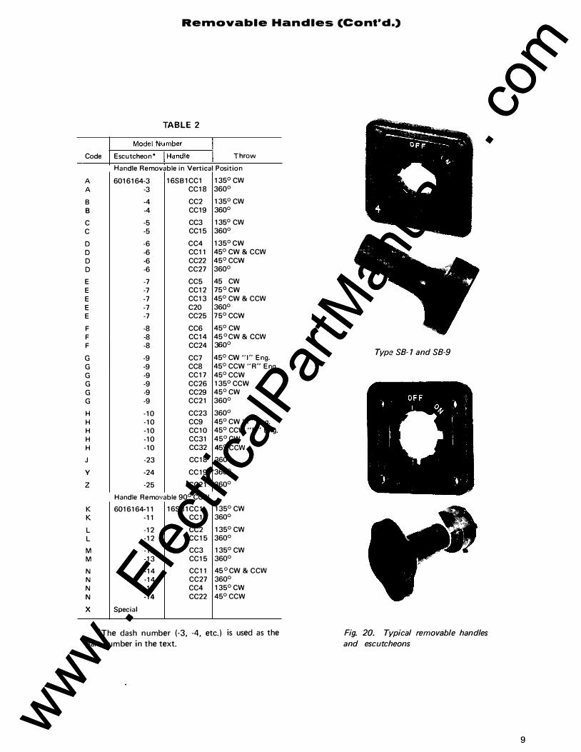
Removable Handles (Cont'd.)
TABLE 2
Code Escutcheon* Throw
Handle Removable in Vertical P osition
A 6016164-3 16SB1CC1 135° cw A -3 CC18 360°
B -4 CC2 135° cw B -4 CC19 360°
c -5 CC3 135° cw c -5 CC15 360°
D -6 CC4 135° CW
D -6 CC11 45° CW & ccw D -6 CC22 45° CCW D -6 CC27 360°
E -7 CC5 45 cw E -7 CC12 75° CW E -7 CC13 45° CW & ccw E -7 C20 360° E -7 CC25 75° CCW
F -8 CC6 45° CW F -8 CC14 45 ° CW & ccw F -8 CC24 360°
G -9 CC7 45° CW "I" Eng.
G -9 CC8 45° CCW "R" Eng.
G -9 CC17 45° CCW G -9 CC26 135° CCW G -9 CC29 45° CW
G -9 CC21 360°
H -10 CC23 360°
H -10 CC9 45° CW "I" Eng. H -10 CC10 45° CCW "R" Eng. H -10 CC31 45° CW H -10 CC32 45° ccw J -23 CC18 360°
y -24 CC19 360°
z -25 CC21 360°
Handle Removable 90° CCW
K 6016164-11 16SB1CC1 135° cw K -11 CC18 360°
L -12 CC2 135° cw L -12 CC15 360°
M -13 CC3 135° cw M -13 CC15 360°
N -14 CC11 45 ° CW & ccw N -14 CC27 360° N -14 CC4 135° CW
N -14 CC22 45° CCW
X Special
*The dash number (-3, -4, etc. ) is used as the part number in the text.
Type SB- 1 and SB-9
Fig. 20. Typical removable handles and escutcheons
9
www . El
ectric
alPar
tMan
uals
. com
www . El
ectric
alPar
tMan
uals
. com

Temperature-meter SlNitches
T emperature-meter switches are
fu rnished with pa l ladium contacts,
wh ich have a constant resistance
factor. This is necessary because
cal i brated leads are norma l ly u sed in a
temperature-meter circu it, and si lver
contacts wou ld resu lt in a variable
resistance factor and cause f luctu ation
in meter read ings.
Fig. 2 1 shows a temperatu re-meter switch, Model 1 6S B 1 CE52, read ing four RTD's, on a two-wire circu it w ith a TEST and an O F F posit ion. On a two-wire circu it, you can transfer up to seven coi l s w ith an O F F posit ion, or s ix coi l s with a TEST and an O F F posit ion.
Fig. 22 shows a Model 1 6S B 1 CE55 read ing three RTD's, on a three-wire
circuit with a TEST and an O F F
position. On a three-wire circu it, you
can transfer up to six coi l s with an
OF F position, or five coi l s with a
TEST and an O F F position . When it i s
required to transfer more RTD's than
the max imum for a given switch, two
switches with a removable hand le may
be used.
NO TE: FOR A DDITIONA L CONTA CT DIA GRAMS SEE PAGES 39 A ND 40.
TEST METER TEMPERAT URE METER Off �
T RANSFER SWITCH, � TRANSFERS T WO WIRES TO .r,.
,jo FOUR COILS, WITH T EST 8 OF F.
' 2 MODEL NO. 16S81CE52
CONT ACT S POSITIONS HANDLE END ... ... ... " " " :5 4 .. 3 £ 2 c
I II----()........ 2 0-1 1-o
3 4 0--jl ,... lf-o r 5 ,.../ 6 0-f. ........ 1-o 7 """"' ·� D-1 r 9 ,.../ 1 0 0--1 ...., 1-o I I 12 0-i r---0---t 1-o
T EST RESISTOR
I 2 3 X 4 X
5 6 X 7 8 X X X 9
10 X I I 12 X X X
4 3 2
X
X
... " - I .5
X
X
X X
DET EC TOR COILS IN M ACHINE
... " �
X
X
- ... Ill " .,_ 1- c
X X X X
-... 0 X
X
Fig. 2 1. Temperature meter switch, Model 16SB 1CE52
10
TEST METER T EMPERA T URE METER Off T RANSFER SWIT CH,
II) � ,., T RANSF ERS THREE WIRES TO THREE COILS, WI TH TEST 8 OF F
� ' MODEL NO. 16S81C E55
CONT ACT S POSIT IONS ... ... ... ... ... ... ... .. ! HANDLE END � .., � .., " .., � Ill .... 3 c: 2 c c:1 - j! ....
I 2 <>-11-<>-ll-0 3 4 0--1 r-<:>-1 1-0 5 6 0--i 1-<>-i 1-0 7 8 o1f-o-ii-O 9 10 ��1-6 II 12 o-1�1-0
c
I 2 3 4
5 6 7 8 X 9 10 X X I I
12 X X
c c c c 0 X
X X X X
X X X X X X
X X X X
X X X X
X X X X
115 V A-C SOURC E x---t Y---t
FUSES -o
A r-t-----, 80 co �I
T E S T or 2 RESISTOR L.......+--+-1n" '--'""' '""'�+----, '---+----+3:;,.�o · '-Jo-� �o-::4+-----.
,___+s::..:::.o r'\__. oo-:6+----n .----+7:--o� � -)-a-=+----.
a-
.-------+-'-'-� �0 � g*FII�"'++----.
AO <)C A;> �C 8 l B
3 2 I DETECTOR COILS IN M ACHINE
Fig. 22. Temperature meter switch, Model 16SB 1CE55
www . El
ectric
alPar
tMan
uals
. com
www . El
ectric
alPar
tMan
uals
. com

*ADD 1/4 TO A & B DIM. FOR LARGE COVER
NO. OF STAGES A* B *
1 5-1/16 7-7/16
2 5-13/16 8-15/16
3 6-9/16 10-7/16
4 7-5/16 11-15/16
5 8-1/16 13-7/16
6 8-13/16 14-15/16
7 9-9/16 16-7/16
8 10-5/16 17-15/16
9 11-1/16 19-7/16
10 11-13/16 20-15/16
11 12-9/16 22-7/16
12 13-5/16 23-15/16
13 14-1/16 25-7/16
14 14-13/16 26-15/16
15 15-9/16 28-7/16
16 16-5/16 29-15/16
Special Svvitch Outlines
Figure 23 and F igure 24 cover outl i nes of some special switches not included in G EA-4746G.
OUT L I NE
NOTE: ALL DIMENSIONS ARE IN INCHE S
�������- c ------------� PANEL DRILLING - FRONT VIEW
TWO SWITCH TANDEM SB-1
Crank oper. max. throw from vertical 45° Crank oper. max. throw from vertical 75° Gear-operated (360° rotation)
THREE SWITCH TANDEM SB-1
Crank oper. max. throw from vertical 45° Crank oper. max. throw from vertical 75° Gear-operated (360° rotation)
FOUR SWITCH TANDEM SB-1
Crank oper. max. throw from vertical 45° Crank oper. max. throw from vertical 75° Gear-operated (360° rotation)
c 6-3/4
8-1/4
7-1/2
10
11-1/2
11
13-1/4
14-3/4
14-1/2
D E F
1-3/4 7-1/2 3-1/4
2-1/2 9 3-1/4
2 8-1/4 3-1/2
5 10-3/4 3-1/4
5-3/4 12-1/4 3-1/4
5-1/2 11-3/4 3-1/2
5 14 3-1/4
5-3/4 15-1/2 3-1/4
5-1/2 15-1/4 3-1/2
a: w > 0 u _J _J <{ :2 (/) a: 0 lL
N
G
a: w > 0 u w l!) a: <{ _J a: 0 lL
� -c\1
(This data is subject to change without notice)
Fig_ 23_ Tandem-switch outline 1 1 www . El
ectric
alPar
tMan
uals
. com
www . El
ectric
alPar
tMan
uals
. com

1 2
Special SlNitch Outlines (Cont'd.)
"C"X2 � 16 WIDE ----+.W+
SB-switch with Yale Lock above the switch. For "A" and "8", use standard dimensions plus "0", depending on panel thickness.
SB-9 SWITCHES
STANDARD DIMENSIONS IN INCHES
STANDARD COVER 12 WIRES OUT TOP LARGE COVER
NO. OF AND 24WIRES 24 WIRES OUT STAGES OUT BOTTOM TOP AND BOTTOM
A B c A B c
1 4-718 8-318 5·118 8·518
2 5-518 9-718 5-718 10-118
3 6-318 11-318 6-518 11- 518
4 7-118 12-718 7-318 13-118
5 7-718 14-318 8 -118 14-518
6 8-318 15-718 8-7/8 16-118
7 9-318 17-318 9-518 17- 518
8 10-118 18-718 10-318 19-118
9 10-718 20-318 4 112 11-118 20-518
4 15116
10 11- 518 21-718 11-718 22-118
11 12-318 22-318 12-518 23-518
12 13-118 24-718 13 -318 25-118
13 13 -718 26-318 14-118 26-518
14 14-518 27-718 14-718 28-118
15 15-318 29-318 15-518 29-518
16 16-118 30-718 16-318 31-118
(This data is subject to change without notice)
Fig. 24. Dimensions, control switches with Yale Lock www . El
ectric
alPar
tMan
uals
. com
www . El
ectric
alPar
tMan
uals
. com

--
Fig. 25.
Fig. 26.
Fig. 27.
Fig. 28.
Fig. 29.
C o ntact D i a g ra m s for S BM Svvitch
VOLTMETER SWITCH,
double-pole, s ing le-throw,
Model No. IOAAOOI. Knurled handle.
VOLTMETER SWITCH,
double-pole, double-throw,
Model No. I OAA 002. Knurled handle.
VOLTMETER TRANSFER
SWITCH, three-phase,
transfers four wires
phase-to-neutral,
Model No. I OAA003. Knurled handle.
VOLTMETER SWITCH,
Phase-to-phase, or
phase.to-neutral,
Model No. IOAA004. Knurled handle.
VOLTMETER SWITCH,
four circuits, two wires,
Model No. I OAAOOS. Knurled handle.
VOLTMETER
OFF 01-
0
VOLTMETER
OFF ' <?
0
VOLTMETER
u_ u_ 0
2 ' .r
0
VOLTMETER
2-3 ,, ,f/
lL. lL. 0 0
VOLTMETER
2 ' .$ OFF 0 4
x in all contact diagrams denotes contacts closed
�ONTACTI HANDLE POSITIONS
END rm � ON OFF
<>lfoolr> X 12 X
ONTACTS POSITIONS HANDLE
END
§If � 1:;: 2 o I
"i�f:2 X O!r<biio 3 X
4 X
�ONTACTI POSITIONS HANDLE END I rsrnr- u_ � 3 2 I u_ 0
;;;pl�ol2 X 01�"11<> 13 X 14
ONTACTS HANDLE
END
:Ji5 8� I ?I fool
��� 12 3 14
ONTACTI HANDLE
END rsrnr-� '"ff'!r>12 <>jrh,fo 3
14 <>I if'1io 5
16 �I<> IB
_..., N "-' ' , ..._ "'"' -0 X
XX
lL. lL. 4 3 2 I 0
X X
X X
X X
Source
3
N 3 2 I
��----
3-phose 3-wlrP
4 3 2
�-
4
I Voltmeter I I
rf.o3
jumper to 1-2 when connecting
h 2!
d' 4?
I
swilch 3 ,P,4w.
3-phose, 4-wire {future alternate connection)
I Voltmeter I I
r I )6 2 b 3 h 4
J 5 f6 6 6 r 7 h sb l
1 3 www . El
ectric
alPar
tMan
uals
. com
www . El
ectric
alPar
tMan
uals
. com

Fig. 30.
Fig. 3 1.
Fig. 32
Fig. 33.
Fig. 34.
14
Contact Diagrams for SBM Svvitch
VOLTMETER TRANSFER
SWITCH, three-phase, trans
fers four wires phase-to-phase
and phase-to-neutral,
Model No. I OAA006. Knurled handle.
VOLTMETER SWITCH, two
three-phase, three-wire
circuits,
Model No. I OAA007. Knurled handle.
AMMETER TRANSFER SWITCH,
three CT's (connect at
end of secondary),
Model No. IOAAOOB. Knurled handle.
AMMETER TRANSFER SWITCH,
three CT's with off
(connect at end of secondary),
Model No. I OAA009. For wiring, see Fig. 32. Knurled hand le .
AMMETER TRANSFER SWITCH,
three independent circuits,
Model No. IOAAOIO. Knurled handle.
VOLTMETER OFF
"' /"' C\J
/
0
..;' OFF
VOLTMETER
AMMETER
2
0 UJ
AMMETER
OFF
t<l 0 2
AMM ETER
2 0 "'
x in all contact diagrams denotes contacts closed
�NTACTI HANDLE END 'l J i5 u. _, "'"" 8c;:; 3 2
u. I I 1"-lo "'"' -0 �<>I X
1 2 XXX � 3 X 14 t6"i 5 X X
L--� X
�NTACTI HANDLE END 3 2
:las _, ';':!:: _, (\jU. 8c;:; I I I I 1"-"'"' 0 "'"' -0 � �I<'"' X 2 XX bt671 13 X
:4 X �tool 5 X X
6 XX �i"oj 8 X
�NTAC� HANDLE END :las 8c;:; "'* N * -
fl toOl� X X X X 2 X X �tOOl 3 X X X X
4 X X X !,tOOl 5 X X X X
6 X X
�NT ACTS HANDLE END 'lli5 "-8c;:; *"' *"' *- "-*O
�t<R>i X X X X X X X X X X
�tOOl X X X X X X X X X X
�i<>j X X X X X X X X X X
ONTACTI HANDLE 3 2 END �r-G::i I"'* ** "'* **-�� 12
XX X X X X X X X X
�� 13 X X 14 X X X
p.,� 5 X X X 16 X X X X X X X X
llo� 7 X X X X X X 18 X X
�f<>. 19 X X
--voltmeter
9 'i' I ,--J '-- 3 2 I
u I I 6 6 2 3 6 6 4
5 ! 6 6 7 b b 8
www . El
ectric
alPar
tMan
uals
. com
www . El
ectric
alPar
tMan
uals
. com

Fig. 35.
Fig. 36.
Fig. 37.
Fig. 38.
C o ntact D i a g ra m s for S BM S w itch
AMMETER TRANSFER SWITCH,
two CT's
!connect at end of secondary!,
Model No. I OAAO I I. Knurled handle.
AMMETER T RANSFER SWITCH,
two CT's with off
(connect at end of secondary),
Model No. IOAA012. For wiring, see Fig. 35. Knurled handle.
AMMETER TRANSFER SWITCH,
three independent circuits
with off,
Model No. IOAA013. For wiring, see Fig. 34. Knurled handle.
AMMETER-VOLTMETER
TRANSFER SWITCH, three
phase, three wires phase-to
phase, plus three independent
current transformer circuits,
Model No. IOAA014. Knurled handle.
x in al l contact diagrams denotes contacts c l osed
AMM E T E R
2
0 (>J
AMMETE R
OFF
"' 0 2
AMM E T E R
OFF
2
A M M E T E R VOLT M ET E R
OFF
0
2
f-ONT ACTS HANDLE
END :j� 8� I"'* N * -
yM� X X �2 X X X X
.,� .3 X X 14 X X X X
ONTAC!5 HANDLE
END oU� "-8� *"' *N *- *)5
��� X X X X X �2 X X X X X
I&!� .3 X X X X X 14 X X X X X
p..ONTAC� HANDLE
END "-"-11� 8� "'* ** N* ** -*0
�� X X X X X X X X X X X X X X
1"!601 X X X X X X X X X P.,i601 X X X X X X X X X X X
J11j<)Oj X X X X X X
�lo H- X X X ...___
ON TACT'S , [ I : HANDLE END
§Tf-� * 3 * * pli&011<>12 bitoOI L�
l_4 Oi 1001 � 5 ' 16 X X X X ?I 10011<> X X X
.8 X X X biio .9 X X X
lr fOOi I 12 [�iooj X X 14
X X X X X
! l'i I I' ' I
X X X
I I I
"-"-*2'*'*'*1 *0 X X X X X X X X X X X X X X X X X X X X X rX X X X
X X X X X
X
X X X X
www . El
ectric
alPar
tMan
uals
. com
www . El
ectric
alPar
tMan
uals
. com

-
Fig. 39.
Fig. 40.
Fig. 4 1.
Fig. 42.
16
C o ntact D i a g ra m s for SBM Svvitch
DESCRIPTION ESCUTCHEON & CONTACT DIAGRAM '
AMMETER ON TACT'S VOLT METER HANDLE OFF END
rnrnr- "-AMMETER-VOLTMETER �� r<l 0 - G::. lf3 * * * 2 ** lfl TRANSFER SWITCH, three- X X phase, four wires phase-to- Jrt<501r X X J&t<501 X X neutral, p lus three independ-
2 X X X X X
ent current transformer c i rcuits, ofi<501 X X X X X X X Model No. !OAAO!S. 1�1<5011" X X X X X X X X
XXX Knurled handle. lbiio�lo I X X X
�flilr :2
AMMETER ONTAC� I VOLTMETER HANDLE AMMETER-VOLTMETER OFF END rsrn r- I I "-TRANSFER SWITCH, I "-r<l 0 - G::. * 3* 2lf llf O three-phase, three wires 1<501� X XXX X X phase-to-phase p lus X XX
2 fOb, X X
three current transformers XXX (connect at end of secondary), ��fl X X X X X XX
XXX Model No. !OA A0!6. X '" "" "' XX Knurled handle. l/ni<>oj� I X
X
AMMETER ONTAC!.S VOLTMETER HANDLE AMMETER-VOLTMETER
OFF END 11[5 "-TRAN SFER SWITCH, 8G:; "-"' 0 - * 3 * 2 lf I )f o
three-phase, four wi res � phase-to-neutra l , p lus X X X
2 rMl� X X three current transformers
(connect at end of secondary), X X X X X X X rM1 6 X X X Model No. !OA A0!7. ottfir 8
X Knurled handle. X
of� 1� 9 X
BREAKER CONTROL ON TACT'S HANDLE
...J 0 END CI RCUIT-BREAKER CONTROL ,« C( w« :!'a.
SWITCH, "'<- 0& ili5 <>:-
0 (" 8G:; a: Z >-Model No. 1 OAA 1 00. '"fjll X Pistol-grip handle. 12 X
��I � X X 14 X
Spri nq return
JL in all contact diagrams denotes contacts closed
WtflfNG OIAG.AM
N32 1
l
tJ
3 2 I
if. � �
N32 1
� � -!
"' ;! � �
0. � ;: E -+ .0 .... u com" ,ft Res1stor
� 4
Fuse
Operat inq + X
bus or - y
]A�me
;er]
I n I 66 2 b 3 rl 4 9
!s h 6 7 h 8 o-
l 9 6 6 6
[vol�meter
Ammeter I 0 0 �L I 67, 2 3 4 5 h 6
y 7 b 6:l 9 �··I
6 0 · I Voltmeter
I Ammeter Q Q ,--JL
I h 2
3 4 5 6 7 f6 8 ? 9 � tl
I Vo�m:ter I
"' £ u
! ! 0. 0 -+- o ..c �o-":� Res•stor
� Fuse
Clos1nq bus
T r 1ppmg bus
� � 0
u
I I j
+ X or - y + -
-
II''"
,. .
www . El
ectric
alPar
tMan
uals
. com
www . El
ectric
alPar
tMan
uals
. com

Fig. 43.
Fig. 44.
Fig. 46.
Fig. 47.
C o ntact D i a g ra m s fo r S BM S vv itc h
CIRCUIT -BREAKER CONTROL
SWITCH,
Model No. I OAA I 0 I. Pistol-grip handle.
TRIP SWITCH,
contacts normal ly open,
Model No. I OAA I 02. Pistol-grip handle.
TRIP SWITCH,
contacts normally closed,
Model No. IOAAI03. Pistol-grip handle.
C I RCUIT-BREAKER CONTROL
SWITCH for operating
two breakers,
Model No. I OAA 1 04. Pisto l-grip handle.
SWITCH SUBSTITUTE
for push-button station,
Model No. I OAA I 05. Pistol-grip handle.
BREAKER CONTROL
0
BREAKER C.ONTROL
BREAKER CONTROL
BREAKER CONTROL
BREAKER CONTROL
x ·,n o i l contact d i a g rams d enotes contacts closed
" u ..
ONTACTS § � HANDLE 0: 0: "' "'
� 9- ;; - + .c � u
END 1� $ � il i5 "' " ::> 0.. 0: � � 8G:; 0 z
<>ll<>jii<> X X ��fo X X X ol� X X ��-�1<>1 8 X X X X
Spnng return
ONTACT"5 HANDLE ...J
END 4 a.. " il i5 _ cr 8 G:; cr o f- Z
� � X 2 X
Spnng return
ONTACTS HANDLE ...J
END 4 " i l i5 ��� 8G:; F'� 2
X X Spnng return
ONTACTS HANDLE
END ...J w 4 liz (l) ::i; a_ o cr -8 � � a a: u z >-
lr �-<rr 2 X X X J �if' I 3 X X
4 X Closing coil 5
��!<> 5 X 6 X
ONTACTS HANDLE ...J
END ��� 0.. l§f!r-o cr -G:; o cr z >-
f'�lo X X 2 X X
biio 3 X Spnng return
" u
! .. � � 0
-+- ;::. u
--���T�np�p�,n�g7b�us�- + A l a r m bus
t
� 2 4
6
Tr ip coi l
Tr ip coi l
Closing coil
Contoctor coi l
17
www . El
ectric
alPar
tMan
uals
. com
www . El
ectric
alPar
tMan
uals
. com

Fig. 48.
Fig. 49.
Fig. 50.
Fig. 5 7.
1 8
C o ntact D i a g ra �n s for S BM Svvitch
CIRCUIT-BREAKER CONTROL
SWITCH,
Model No. I OAA I 06. Pistol-grip handle.
BRE AKER CONTROL D ,<:� C( ..._� Os<-" 0
ONTACTS HANDLE
END 'll i5 8 � jo1""'1 1 2
foi�<>i 1 3 14 foi�<>ifo 5
1 6
C I RCUIT-BREAKER CONTROL
SWITCH,
Model No. I OAA I 07. Pistol-grip handle.
BREAKER CONTROL �ONTAC!5 HANDLE
END
: l i5 8 �
o 'O d g' "' "' w w w � � � .. « a. d§ § �
X X
X X X X X X X Spr 1ng return
_J <( :l o._ 0: -_J Q il: Z f-X f-1�-<><>� ' 2 X
CIRCUIT -BREAKER CONTROL
SWITCH,
Model No. I OAA I 08. Pistol-grip handle.
BRtAKER CUN I ROL ONTACTS HANDLE
END :[i5 8 � foii<>o!Jo oi fool I<>
jo11-1Jo
C I RCUIT-BREAKER CONTROL
SWITCH,
Model No. I OAA I 09. Pistol-grip handle.
BREAKER CONTROL ONTACTS HANDLE
END
8 1 � foil-1 /oitoo1Jo joil-1fo jolfoo1fo
S p r 1 n g ret urn
0 "-d � "' "' w w � � .. .. .. .. :o :o a. "' � � u �
X X
X X X X
X X X X Spr1ng return
O il. d � � ffi 5 i :l :o a. -' § .. -o a: z f-
X X
X X X X X X X X X X X Spr1ng return
x in a l l contact diag rams denotes contacts c l osed
Fig. 52.
Fig. 53.
Fig. 54.
CIRCUIT-BREAKER CONTROL
SWITCH,
Model No. I OAA II 0. Pistol-grip handle.
BRE AKER CONTROL ONTACTI HANDLE
END 1l i5 8 � <>ltoo! Jo <>lfoo1fo jo11-1fo
jolfoo1fo
CIRCUIT-BREAKER CONTROL
SWITCH,
Model No. I OAA I l l . Pistol-grip handle.
g u
� W <t :1 a.
"" "' 0: u � f-X X X X
X X X X X
X X X X
Spnng return
BRE AKER CONTROL ONTACTS § � HANDLE
END 1li5 8 � f'11-1 /oitooi oi fool fo jolfo<>ifo �fooiJo I
CIRCUIT-BREAKER CONTROL
SWITCH,
Model No. I OAA 112. Pistol-grip handle.
BRE AKER CONTROL
,<:� 0 (1 ..... � <o& '<." 0
�NTACTI HANDLE
END
81� �fooi jolfoo1Jo jolfoo1fo /oifooifo joi Jool Jo I
.. .. "' "' w � $ :> :o a. c § � �
X X
X X X
X X X X
X X X X
X X X X
Spnnq return
o <o � .. U l-
� � ��� � :o :o a.
§ � � X
X X X X
X X X X
X X X X X X
X X SprmQ return
l'
www . El
ectric
alPar
tMan
uals
. com
www . El
ectric
alPar
tMan
uals
. com

Fig. 55.
Fig. 56.
Fig. 57.
C o ntact D i a g ra m s lor S B M S vvitch
CIRCUIT-BREAKER CONTROL
SWITCH,
Model No. I OAA 1 1 3 . Pistol-grip handle.
BREAKER CONTROL
CIRCUIT -BREAKER CONTROL
SWITCH,
Model No. I OAA 1 1 4 . Pistol-grip handle.
BREAKER CONTROL
<(-� D C � Zos c PULL 0 TO LOCK
CIRCUIT-BREAKER CONTROL
SWITCH,
Model No. I OAA 1 1 5 . Pistol-grip handle.
BREAKER CONTROL
D � C'<o "� s �
PULL 0 TO LOCK
CONTACT5 g !!. u l!' HANDLE ffi � END $ .. §!� � ::E £1: z � � <>1 1<>"1 X X �I<> oil<> X X X <>11<»11<> X X X X <>11<>oil<> X X X X >i l<>oito l
X X X X Spnng return
ONTACT5 "' u HANDLE '3
END ...J .. � 11� (/) ::; '!o j o a:: 8 c::; 0 0:: :::> u z 1- a.
<>ltooj jo 1 X X 12 X
., l<><>l � X X X 14 X X
Spnng ret urn
ONTACT5 9 u "' HANDLE � u
9 END w!:; � §I� ::E a. _, 0: � � f:i1 b-if<>o1 X X X fli"'ii" X X X X X X X �l<>oi X X X X
SprlnQ return
x in all contact diagra m s denotes contacts closed
Fig. 58.
Fig. 59.
Fig. 60.
CIRCUIT-BREAKER CONTROL
SWITCH,
Model No. I OAA 1 1 6. Pistol-grip handle.
BREAKER CONTROL
� o c<o -<.: s� PULL 0
TO LOCK
CONTACT"S HANDLE
END
§l� �l<>oil<> �l<>oijo �1<»11<>
CIRCUIT-BREAKER CONTROL
SWITCH,
Model No. I OAA 1 1 7. Pistol-grip handle.
BREAKER CONTROL ���u END
1 §1 � <>i f<>o1 1 � " � "'
-"
... -"·
CIRCUIT -BREAKER CONTROL
SWITCH,
Model No. I OAA 1 1 8 . Pistol-grip handle.
BREAKER CONTROL
� o c<o -<.: sc PULL 0
TO LOCK
CONTACT! HANDLE
END
§1� <>ltooj �I<> <>I jol!o<>llo �I<><>! to
dl� "' � � g � � 2 Q.. -'
2 �� X X X X X X X X X X X X X X X Spnnq re turn
I� lg ���� I� � � �1:5
"9 rn
Q O. "' d � g ffi "' t: � I? .. .. ...J SH� X X X X X X X X X X X X X X X X Sprin retyrn
1 9 www . El
ectric
alPar
tMan
uals
. com
www . El
ectric
alPar
tMan
uals
. com

-Fig. 6 1.
Fig. 62.
Fig. 63.
20
C o ntact D i a g ra m s for S BM Svvitch
Cl RCU IT -BREAKER CONTROL
SWITCH ,
Model No. 1 OAA 1 1 9 . Pistol-gr ip handle.
BREAKER CONTROL
<( D "�
PU LL 0 TO LOCK
r>NTACTS HANDLE
END
§[� <>1 �<>11<>1 � "1 1'><>11<> .3
1 4 ., , .. ,, 1 5
1 6 f>j�<>i\o 18
C l RCU IT -BREAKER CONTROL
SWITCH,
Model No. 1 OAA 1 20 . Pistol-gr ip handle.
BREAKER CONTROL
'< D � "
P UL L 0 TO LOCK
ONTACTS HANDLE
END
§!!,-� 1<>1�<>11<> 1 2 o<lo<>llo .3
1 4 f' �oi\o 5
1 6 <>ltoo1 to 1 8
C I R CU IT-BREAKER CONTROL
SWITCH,
Model No. 1 0A A 1 2 1 . Pistol-grip handle.
o a. " d � u "' "' g � w t: ::: 0 "' " " .... ,. � � j _j � "' a: :> � >- a. X X X X X X X X X X X X X X X X
Spr1n9 ret u r n
d a. " � u "' "' g w :o' 0 ... � � ....
<ll :o ,. a. ...J O tt: o: - ...J ...J o o O: =>
z z >- Cl.
X X X X X X X X X X X X X X X X X Spr1ng return
BREAKER CONTROL ONTAC!S o <e " � "' u U >- g HANDLE :$ D C} .._0 '
PU LL 0 TO LOCK
OS('
"' � END w � ... �
§!!,-"' " .. ,. :o a. ...J
...J "' "' _ ...J � :il l!: :> u :il f- Cl. <>1 �->11<> X
1 2 X <>I I<> <>I to .3 X X
1 4 X X <>1�<>1\o 5 X X X X
16 X X <>11<><>1\o X X
18 X X Spr1ng return
x in all contact diagrams denotes contacts closed
Fig. 64.
Fig. 65.
Fig. 66.
C IRCU IT-BREAKER CONTROL
SWITCH,
Model No. 1 OAA 1 22 . Pistol-grip handle.
BREAKER CONTROL ONTACTS " 9 HANDLE
<( D C' END "� <os<" :[ 1:5 P U L L 0 8 � TO LDCK �1'>�1- 2
I <>I I'> <>I I- 3 4 fi 1'><>1\o 5 6
ol too-1\o 8
CIRCU IT-BREAKER CONTROL
SWITCH,
Model No. 1 OAA 1 23. Pistol-g r ip handle.
0 .... Q. ...J _ ...J ...J a: ::> >- Q. X X X X X X X X X X X X X X X X X
pr1 nq return
BREAKER CONTROL ONTACTS d � " � HANDLE
D END <.,«-'<( c<o S(- : [ 1:5 PULL 0 8 �
TO LOCK <1�<>1 <>!�<>Ito �1'><>1\o fi�oi\o F1 fooi to I
C IRCU IT -BREAKER CONTROL
SWITCH,
Model No. 1 OAA 1 24 . Pistol-grip handle.
BREAKER CONTROL
D �«. c<o -<.: :S(-P U LL 0
TO LOCK
f:oNTAC!_S HANDLE
END
§[ � <>1 1<><>1 <>1 1<><>1 ol l<>oi fo <>lloojfo <>I 1<><>1 1<> I
� � ...J 0 "' " " ....
<ll :o :O Cl. -' O o: « - -' ...J o o il: =>
z z >- a. X X X X X X X X X X X X X X X X X X X X X
o !!. "' d � u :!> ffi 0 ...J t ::: 0 .. .. .... "' '" :o a. ...J O tt: "' - ...J
u :il :il l!: :> >- a. X X X X X X X X X X X X X X X X X X X X Sprmg r e u rn
www . El
ectric
alPar
tMan
uals
. com
www . El
ectric
alPar
tMan
uals
. com

-
Fig. 67.
Fig. 68.
Fig. 69.
Fig. 70.
C o ntact D i a g ra m s fo r S BM Svv itch
WATTMETER TRANSFER
SWITCH, two cu rrent coi ls ,
Model No. I OA A O I B. Knurled handle.
WATTMETER TRANSFER
SWITCH, three current coi ls,
Model No. 1 OAAO 1 9 . K nu rled handle .
WATTMETER TRANSFER
SWITCH, two current
and two potential coi ls,
Model No. I OAA020 . Knurled handle.
POWER-FACTOR SWITCH,
one or two cu rrent coi ls ,
Model No. 1 OAA02 1 . Knurled handle .
x i n a l l c o n tact d i a g r a m s d e n o t e s c o n t a c t s c l osed
WAT T M E TE R
O F F
0 0 z
W AT T M E T E R
O F F
0 0 z
WAT T M E T E R
O F F
0 0 z
P F S W I TC H
O F F
0 0 z
ONTAC� I HANDLE
END �� �1� z 8 r;:; o *
�iJO!to X 1 2 X X
l.ti<><>! 3 X X · 14 X X "i !AJ 5 x .x
1 6 X X
ONTACTS I i I HANDLE I .
END I I :[� "" 8 r;:; � *� X X if! toO-! I" 2 X X l <>i!o<>l 3 X X
4 X X <>�if! I 5 X X
1 6 X X l r�<>�to ·x x
1 8 X X I I.! I<> 19 X X
� XX � 1o o1 1 4 X X
;()NT ACT'S I i I HANDLE END I I � � � 61*1�1 8 , r;:;
fii<'Ojl" X X 1 2 XIX i " I<' 3 X X
S o u rce
3 2
Source 3 2 I
Sou rc e 3 2
Current Co i ls
Potent1al Co 1 l s
2 1 www . El
ectric
alPar
tMan
uals
. com
www . El
ectric
alPar
tMan
uals
. com

Fig. 7 1.
Fig. 72
Fig. 73.
Fig. 14.
22
C o ntact D i a g ra iTi s for S BM S vv itch
POWER-FACTOR SWITCH, one
current and two potential coi ls,
Model No. 1 0A A 022 . Knurled handle .
POWE R-FACTOR OR WATT
METER REVERS ING SWITCH,
Model No. J OAA023. Knurled handle.
GOVERNOR O R RHE OSTAT
MOTOR CONTROL SWITCH ,
Mode/ No. J OAA066 . Lever handle .
P F METER
O F F
0 0 z
W AT T M E T E R
0
GOV E R N O R
MOTOR CONTROL
MOTOR CONTROL SWITCH,
Mode/ No. J OAA067. Pistol-grip handle.
x i n all contact d iagrams denotes contacts closed
Ot·HACTS I I HANDLE
END I I
"l i z , c_
8 � z, ,u_ 0'* 0
l rtn1�< I X , X 2 X X IL� � to 3 X X , ot fo<>l fo 5 xjxj I 6 X X
ON TAW , I I HANDLE :�1 E ND �r- I c , l-1 o :
8] 6100:� r- c::. o< ,OOjtol2 X ' • X I � iO "' �" 3 ' . x
1 4 X 6i rl i>i fo 5 ' X 16 X ' <>� rl i>l r X , 1 8 X
�ONTAC� HANDLE
.J END ��� o i5 3: Cl: -
8 1 C::, O <t ....J ZI O::
frr&jto 2 � X X
fb; .OO. 3 X X 4 X X "' 'f' ' 5 X
6 X /o'thito X
8 X
ONTACTS J�: I HANDLE END
-;::;rzr- :;::1� c_l 0 w '"lo OI 8 c::, )di[z >-- 1 _ en
� � !" X 1 2 X X
---
L 1m ll swdch
Potential Cal ls
of wattmeter
Potenti a l Co i ls of Wattmeter
L1m1! SW I ICh
Lower
L l'rn 1 f SWitCh
"Ra 1se"
Current
Col i
Potential Coils
Pot. Trans .
Auto Trans
L•m" '�' R o • s e "
,
mot or 2 + ' S e r � e s m o t o r SW i fCh
"Low er" 3 4 - Jumpe rs shown d o t t e d
6 �7 furn 1shed w 1th sw1 !Ch T o be r e mo v e d f or
L 1 m 1 t 7 8 l h 1 s hook - u p SWI !Ch
" R " 0 1 5 e S h u n t motor
3 2 I
H-------1·s:0
www . El
ectric
alPar
tMan
uals
. com
www . El
ectric
alPar
tMan
uals
. com

Fig. 75.
Fig. 76.
Fig. 77.
Fig. 78.
C o ntact D i a g ra m s fo r S BM Svvitch
SYNCHRONIZ ING SWITCH,
machine-to-bus
with interlocks,
Model No. I OAA024 .
Removable oval handle,
Cot. No. 23WW I 4 5.
SYNCHRONIZING SWITCH,
running and incoming,
Mode / No. I OA A 02 5 .
Removable oval handle,
R c = 2 3Wl2 3 5 ,
I =-= 2 3 WR2 3 5 .
SYNCHRONIZ ING SWITCH
between machines without
potential transformers,
Model No. I OAA026 .
Removable oval handle,
Cot. No. 2 3 WW I 2 3 .
MOTOR CONTROL SWITCH
lor spl it-field motors,
Model No. I OAA065 .
Pistol-grip handle.
SYNCHRON I Z I NG
O FF
01-0
SYNCHRON IZ l N G
O F F
0
0
MOTOR CONTROL
c,'<-- <o �� �(; 0 -9
x in a l l contact d iagrams denotes contacts c l osed
ONTAC� fiANDLE
END rnrn� u.
?::; z u. 0 0
oJt<>ol i<' 1 2 X oJJooJfo I �
14
ONTAC� fiANDLE
END rnrn� u.
?::; u. I o R
oJ � i<' X 1 2 X
oj fo 3 X
O�HAC� I� I HANDLE
END .� I �� z <{ ' 8 � I ...J I i� R o� f-'1-l r X 2 ·X ' o� !A1 r 3 x
-� '! .X
�ONTAC� fiANDLE
END ...J O:: « w 81� � � 1:0 O <l ...J Z O::
joli<ll>j X [2 X Spring return
2-t���-------------------3·-+���-------------------
I �------------------------�� 2 �r-------------------�� 3 -+�--------------------��
Limit switch
" Lower "
L 1m it switch
u Raise II split f1eld motor
+
23 www . El
ectric
alPar
tMan
uals
. com
www . El
ectric
alPar
tMan
uals
. com

-
Fig. 79.
Fig. 80.
Fig. 8 1.
24
C o ntact D i a g ra m s for S B M Svv itch
B.
S I NGLE- OR DOU BLE-POLE
s ingle-throw,
Model No. 1 0 A A 0 2 7.
With spring return,
Model No. 1 0AA028 .
Oval handle.
�TAC� HANDLE
END OFF 0 � 0 81 � I� t:::
0
THREE- O R FOU R-POLE,
i ingle-throw,
Model No. 1 OAA029 .
Wi th spring return,
Model No. 1 0A A 030 .
Ova l handle.
fi�'1 X 1 2 X
f:<JNTACTS HANDLE
END ... O F F Q '} 0 81� Z Lo. offoo-j foi�"i
FIVE- O R S I X-POLE,
s ingle-throw,
Model No. 1 OAA03 1 .
With spring return,
Model No. 1 0A A 0 3 2 .
Oval handle.
O FF Clz, 0
f:oNTAC� HANDLE
END l[ i5 8 � �fool )a f>i fool �I<> olio
c .
u.. z u.. 0 0 X X X X X X
0 X 2 X 3 X 4 X
SEVEN- OR E IGHT- NINE- OR TEN-POLE, D. ELEVEN- OR TWELVE-
POLE, s ingle-throw, s ingle-throw, POLE, s ingle-throw, Mode/ No. 1 0A A 033. Mode/ No. 1 0A A 03 5 . Mode/ No. 1 0A A 0 3 7 . With spring return, With spring return, W i t h spring return, Model No. 1 OAA034 . Model No. 1 OAA036 . Model No. 1 OAA038 .
x i n a l l c o n tact d iagrams denotes contacts c l osed
Fig. 82
Fig. 83.
Fig. 84.
S INGLE-POLE, double
throw with off,
Model No. 1 OAA039 .
Wi th spring return,
Model No. 1 0A A 04 0 .
Oval handle.
�NTAC� HANDLE
END ... ... " OFF <?
0 8 1 � N O -
of� jo
DOU BLE-POLE, double-throw
with off,
Model No. 1 0A A 04 ! .
With spring return,
Model No. 1 0A A 0 4 2 .
Oval handle.
J 1 2 X
�TACTS HANDLE
END
X
... , OFF <? 0 §]� �� -
B.
lol�!o '2 X ��
TH REE-POLE, double-throw
with off,
Model No. 1 0A A 06 8 .
With spring return,
Model No. 1 O A A 043 .
Ova l handle.
�NTAC� HANDLE
END " OFF <? lli5 8 � 0 of�to "i�i" ��jo
c.
X X X
::3:: 4 X
... ... 0 -X
X X
X X
FOUR-POLE, double- FIVE-POLE, double-throw with off, throw with off, Model No. 1 0A A 044 . Model No. 1 0A A 04 6 . With spr ing retu rn, W i t h spring return, Model No. 1 0A A 045 . Model No. 1 0A A 0 4 7 .
D . S IX-POLE , doublethrow with off, Model No. 1 0A A 0 4 7 . W ith spring return, �,, Model No. 1 0A A 04c,
www . El
ectric
alPar
tMan
uals
. com
www . El
ectric
alPar
tMan
uals
. com

Fig. 85.
Fig. 86.
Fig. 87.
C o ntact D i a g ra m s fo r S B M S vv itch
S INGLE-POLE, double-throw,
Model No. J OAA050. Oval handle.
0
ONTACTS HANDLE
END
: ( i5 8 G:; N -
X oito<>l 2 X
DOU BLE-POLE, double-throw,
Model No. 1 0A A 05 1 . Oval handle.
f-ONT ACTS HANDLE
END
0 ':\i5 8 c;:; N -
X <>i tol>i i<' 1 2 X
THREE-POLE, double-throw,
Model No. J OA A 0 52 . Oval handle.
' <? 0
<>1 !01>1 1<' 3 14.
ONTACTS HANDLE
END
: \ i5 8 c;:;
X X
N -
X oi � i" 2 X oif� <>i � fo
B . FOUR-POLE, double-throw, Model No. J OAA053.
C. FIVE-POLE, double-throw, Model No. J OAA054.
j 4 5
16
X X
X X
D. S IX-POLE, double-throw, Model No. J OAA055.
E. SEVEN-POLE, double-throw, Model No. J OAA056.
x i n a l l confect d i a g ra m s denotes contacts c losed
Fig. 88.
Fig: 89.
Fig. 90.
S INGLE-POLE, three-throw,
Model No. 1 0A A 057. Oval handle.
ONTACTS HANDLE
END ' 2 -3 :(i5 0 8 c;:;
<>i to'>1 i<' 2 ..-, N -
X X
ol io 3 X �--
Sf NGLE-POLE, four-throw,
Model No. 1 0AA 058 . Oval handle.
3
S INGLE-POLE, five-throw,
Model No. J OAA 059. Oval handle .
'\. 3 9 - 0 ()>
ONTAC� HANDLE
END
1§1Ir-G:; loi tol>i i<' 1 2 <>i !Ol>1 io .3
4
ONTACTS HANDLE
END �l i5 8 c;:;
<>1!01>11" oi!Ol>11<> olio
" "' N -X X
X X
"' " "' N -
X X
X X
X
25 www . El
ectric
alPar
tMan
uals
. com
www . El
ectric
alPar
tMan
uals
. com

Fig. 9 1.
Fig. 92
Fig. 93.
26
C o ntact D i a g ra m s fo r S B M S \N itch
SINGLE-POLE, s ix-throw,
Model No. I OA A060.
Oval handle.
I <? 0 (JJ
c5' D< 5
ON TACT'S HANDLE
END : ji5 8 � '""" ol � fo y <>1 � 1<> 3
4 <>i i6bl i" 5 X
fi X
SINGLE-POLE, seven-throw,
Mode1 No. 1 0AA06 1 .
Oval handle.
S I NGLE-POLE, e ight-throw,
Model No. 1 0AA062 .
Ova l handle.
� I "" ..... 0 (JJ
c5' t> 5
ON TACT'S HANDLE
END 'll i5 8 � " "' <>i f¢l>j fo 12 <>l � fo 3
r4 <>i � fo 5
!; X
alto rx
ONTACTS HANDLE
END
:li5 8 � ., ,._
f,1�fo
�i6bll<> <>i�fo
ol fOOiio X X
" "'
X X
<() <f
X X
"' "'
X X
x in a l l c o n tact d iagrams denotes c o n tacts c l osed
94.
N -
X X
<') N -X
X X
Fig. 95.
" "' N -X
X X
X
DOUBLE-POLE, lour-throw,
Model No. I OAA063.
Ova l handle.
3
ON TACT'S HANDLE
END :!� 8 � <>I�
<>l�jo f,1��i oi��
DOUBLE-POLE, eig ht-throw,
Model No. 1 0AA064.
Oval handle.
" "'
X X
X X
�NT ACTS HANDLE
END
N -
X X
X X
l§rnr-� Ia: ,._ "' "' ��to
ol � io <>li6blfo
X X
oitJl>ll<> X X
<>1 1&1 I I <>1�1<> 1 2
oi tJl>l li X X
<>l t<lb1 to f5 X 16 X
" "' N -
X X
X X
X X
X X
www . El
ectric
alPar
tMan
uals
. com
www . El
ectric
alPar
tMan
uals
. com

C o ntact D i a g ra m s for S B -1 Svvitches
Fig. 96.
'ig. 97.
Fig. 98.
Fig. 99.
VOLTMETER SWITCH,
double-pole, s ingle-throw,
Model No. 1 6S8 I CA 1 .
Knurled handle.
VOLTMETER SWITCH,
double-pole, double-throw,
Model No. 1 6S8 1 CE27.
Knurled handle.
VOlTMETER SWITCH,
phase-to-phase or
phase-to-neutral,
Model No. 1 6S8 1 CF1 1 .
Knurled handle.
VOlTMETER SWITCH, three
phase, phase-to-phase,
phase-to-neutral,
Model No. 1 658 1 CF 1 6.
Knurled handle.
Fig. 100. VOLTMETER TRANSFER
SWITCH, three-phase,
four wires, phase-to-neutral,
Model No. 1 6S8 1 CF22.
Knurlc;d handle.
I I I I
I
x in all contact d i a g ra m s denotes contacts c l osed
VOLTM E T E R
OFF 0-z,
0
VOLTMETER
OFF ' <?
0
VOLTMETER
It 0 0
VOLTMETER
VOLTME T E R
2 ' ,f t 0 0
\ '
I I I I '
I
ONTACTS HANDLE
END
§ffi- '"-Zu.. 0<0 """ X
2 X
ONTACTS HANDLE I
END
if- � i 2 '0 I
� t-o-1!" 2 X X
� � !<> 3 X 4 X· ·
j>11ooj 1 2 X X 1.. � 3 X ., 4 X
�ON TACT'S HANDLE
END I ! "! l i5 81 � I - I'() (\I u.
3 2 1 � � � �
i.j,f X X
ONTACTS HANDLE
END
"! I i5 "' 81 � 3 2 I � 3 • 3
b,' 1 4 X X X
Source Vol;me
?
ter I I 6 6 26
Source 2 I Vo�tm eter I Source I
I I � � � 2 -
3
Vo lt Source meter
@� 3-phose 3- wire
Source N 3 2 I
� �� 3
N 3 2 I
4
Source Remove Vo l t
��']" Move this Jumper to 1-2 when connecting SWitCh 3<j>,4SW
Jump�r not furn1shed w1th switches
3-phos&, 4 - w�re (future a l ternate connect ion )
N
Voltmeter J I
.-+--+--o '
27 www . El
ectric
alPar
tMan
uals
. com
www . El
ectric
alPar
tMan
uals
. com

Fig. 101.
Fig. 102.
Co ntact D i a g ra m s to r S B-1 Svv itches
VOLTMETER TRANSFER
SWITCH, two three-phase,
three-wire circuits,
Model No. I 6S8 I CF23;
Knurled handle.
AMMETER TRANSFER SWITCH,
three independent circuits,
Model No. I 6S8 I CA 7 .
Knur led handle.
VOLTMETER
OFF I "0' /?
"! 0 N N ,;.
/ ,, "'
OFF
A MME TE R
2
0
ONTACTS I II I I HANDLE
; , I i END
I I
�- I ' ' I - 101N'�I_!roiNII.L.. , ,;, � � ��,;,1�1.:.. �11 8 r;:;
f"�! X X 1 2 X X
;'t\: � X X 1 4 X X I
'?"·�-� 5 :x 1 6 X .'�'r<ft rx-· ,x
ONTACTS I ' I I HANDLE I I
END I I I � I f5 I • I I i ' 8 1 G:; 3i*i*'* 2 *'*'*' I , ir-'1-<>--1 2
X X X X X X X X X X �31<> 3 X X ,.}1 • 5 x ' x x x : x .x x x �, f-o-1 1 6 X I X X !';�<> X X X :
,� :�. 9 X X X X IX X 'X X I X X �� I X X
3 2 I I Voltmeter I 3 2 I
I 2 3 4 1� :1
--------------------------�----------------------------�------------------------�
Fig. 1 03. AMMETER TRANSFER SWITCH,
three i ndependent circuits
with off,
Model No. I 658 1 CA I 5. F o r w i r i ng, see F i g.
1 02 . K n u r l ed h a n d l e .
AMMETER
{< 2 0� 0
0
ONTAC!_S I I HANDLE END 11* ':l z u. 8 � * 2 * :s I* I
flf-<>11<' 2 X X X X X X X X
� I<> 3
if!f-<>-lfo 5 X X X X X X X X 6 X
Jblt<> X
]yif-o-1 9 X X X X X X X X I X X J� io I X
�'
-------------------+--------------------+-------------------- """
Fig. 1 04.
28
AMMETER TRANSFER SWITCH,
(connect at end of secondary),
Model No. 1 6S8 1 CA I 8.
Knurled handle.
x in a l l contact diagrams denotes contacts c losed
AMMETER
2 '
0
ONTACTS HANDLE
END
:ji5 8 r;:; flf-<>1 f>ii-<>-i o1 ro1
3 * 2 * 1 X X X
X X X X X
X X X X X X
Source
3 2 A m meter
www . El
ectric
alPar
tMan
uals
. com
www . El
ectric
alPar
tMan
uals
. com

C o ntact D i a g ra m s for S B-1 Switches
- �$C:�IPTION E$CUTCMEON & CONTAC:T OlAGitA� WIJtl�� .. «?IAt;�M ,;?��tr _ ,, I" ' ' ", ' ' ' U � ,,
AMMETER ONTACTS
Fig. 105. AMMETER TRANSFER SWITCH, HANDLE 2 END three current transformers ' .) :l z "-with off "-
0 8 � 3 * 2 * I * � "-(connect at end of secondary),
0 �ro-1 X X X X X 1 2 X X X
Model No. 1 6S8 I CA 1 9. Oi r--o-1 3 X X X X X X For wiri ng, F ig.
1 4 X X X see 5 X X X X X X
1 04. K n u rled handle. fii-o-i 6 X X
AMMETER TRANSFER SWITCH, AMMETER raNT ACTS I Fig. 106. 2 HANDLE
two current transformers END ' .)
31�
with off :]t'i "-!connect at end of secondary),
"- 8 (;'; 2 * I I� � "- 0 0 lr1 1-0-1 r X X X X Model No. 1 658 I CA20. Lc X X X X X
For w i r i ng, see F i g . l �k>-1r 3 X X X X 1 4 X X X X 1 07. K n u rl ed h a n d l e .
Source AMMETER ONTACJ: 3 2 I Ammeter
AMMETER TRANSFER SWITCH, 2 HANDLE , , I Fig. 107. END I I <u two current transformers ' .) rmr- I I !I (connect at end of secondary), 0 (;'; 3'* 2 .* I ::: cti ! :t Model No. 1 6S8 1 CE25. lfl 1-0-1 X :X ' I> C> 4 1 2 x x x x : ll Knurled handle. ji>rk>1 3 X X tl 1 4 x x x x
-=-
Am�meter I AMMETER !cONTACTS Pes it ions Source I HANDLE 4 3 2 I OFF END 4 3 2 I
.. / �f1rf-<> � X X X 'ig. 108. AMMETER TRANSFER SWITCH, X X X
four independent c i rcuits j'i��l 3 X X X X X X X X x x x x X X plus off, 4 X X X X X x x x x x x x x x x :, +- �� 1 �-'!,. 6-11--o--J � X X X Model No. 1 6S8 1 CF I 7. � 6 X X r: Knurled handle. oi�f-<> ; X X X
X X
lr� J, , 9 X X X X X X X X X X X X f1a 1=-I X X X X X X X x x x x x x x Lf-7 1 l�f-o--1 " X X
91 12 X j o I I 12
7
x in all contact d i a g ra m s denotes contacts closed Ov ;.::.; J :--, : j() 29
rr�_s )_� � \
;:::;- ) www . El
ectric
alPar
tMan
uals
. com
www . El
ectric
alPar
tMan
uals
. com

Fig. 109.
Fig. 1 10.
Fig. 1 1 1.
30
C o ntact D i a g ra m s fo r S B-1 S w itches
AMMETER-VOLTMETER
TRANSFER SWITCH, three
phase, three wire, phase-to
phase plus three independent
current-transformer circuits,
Model No. 1 6S8 I CA2 1 .
Knurled handle.
AMMETER-VOLTMETER
TRANSFER SWITCH, three
phase, four-wire phase-to
neutral plus three independ
ent current-transformer circuits,
Model No. 1 658 I CA2 3 .
Knurled handle.
AMMETER-VOLTMETER
TRANSFER SWITCH,
three-phase, three-wire
phase-to-phase plus
three current transformers
(connect at end of secondary),
Model No. 1 658 I CA24.
Knurled handle.
AMMETER VOLTMETER
OFF
0
2
AMMETER VOLTMETER
OFF
0
2
AMMETER VOLTMETER
2 ' .1
t::: 0 0
x in a l l contact diagrams denotes contacts closed
ONTACTS I I I [ I � i I I HANDLE END
O i5 "-u.. 8 � I I i l l I
*13 1** *12!*i*l* l * o X X X X X ·X X X �I 2 X X X X X X X X X X X
�I . � 1 4
� " 5 1 6
�f<j '" I
� � I
�toi' 14
�I<> 15 18 <>1 8
ONTACTS HANDLE
END O i5 8 �
I X X X X X X
X X X X X X X X x � x x X X X X X X
X X X X X X I
X X X X X
X X X X X
I I II I ! I t I : II : I , I I I I ; ' I ' I I I I I
I i ' I I ' ! . I !"-* 31* * '* 2 i* '*f* I ��� X X x x x x x x X X �;, 2 X ' X X X x x x �X X 1X X
�;, ' 3 4 X X X L 5
6 X X X 'i"'r<j X X X X X IX
k I X X X <4to I I x x ·x
�- " 14
16 X
u'f-o-11 3 X X X X X X I' '4 X X X '
"'t<x>f X X T" X X X �f.-,.( I X X
X XJ2( 1X X X
X
I
X
3 2 I
� (� il
7
N 3 2 I
u fJ h_ tl 1
3 2 I
w .J
� l tl J_
L
7
I
IAmme�er
L
l � ":1 '---
5 �
n�l .I t t J 131 14
15 6 6 1 8
1 1 Vol;mebter I
IAmm�ter l L__
l� v-� :t ,, j r-'---n7 1 10
! I I 6 13 1 4 b
1 6 6
Vol :meter I
Ammeter _1_� ,...J L_
I b 2 3 .I 4
5 .I 6
7b l8
' 9 0 1 0
I I lvol:m:te r I
www . El
ectric
alPar
tMan
uals
. com
www . El
ectric
alPar
tMan
uals
. com

C o ntact D i a g ra m s f o r S B -1 S \N itches
Fig. 1 12. AMMETER-VOLTMETER
Fig. 1 13.
Fig. 1 14.
TRANSFER SWITCH,
three-phase, four-wire
phase-to-neutral plus
three cu rrent transformers
!connect at end of secondary),
Model No. 1 6SB 1 CA 2 5 .
Knurled handle.
AMMETER TRANSFER SWITCH,
six current transformers with off. (Connect ot end of secondary)
Model No. 1 6SB 1 CA28, Knurled handle.
AMMETER TRANSFER SWITCH,
six independent circuits plus off. Model No. 1 6SB1 CA29, Knurled handle.
AMMETER VO LTMETER
""-0
2 ' .I
0
ONTAC!5 I HANDLE END
' :ji5 u.
8 � 3 1* 2 f* I * � � 1-<>-1 X X X X
1 2 X X X �1-0-1 3 X X X X X X 4 X X X � 1-0-1 5
6 X �'jll 7 X
8 !>'e<l 9 X
A M M E T E R CONTACTS POS I TION · BACK V I E W
60 F F 1 5 0
4 3
A M M E T E R 60FF 1
5 0 2 4 3
2 HANDLE
I * 1$ END * 6 * 5 * 4 * 3 * 2 1! I .,2 I
1""1t"'f 2 �. 4] '"1_r 4
fll � 6 � �� in ,JO 9
!\, 12J 1 1 >1� I
x in all c o n tact diagrams denotes contacts closed
N 3 2 I
w h
�
Amme ter 9 9 � L
I I J 2 3 6 4
5 6 6 7 8 9
I Vol� m e t e r]
31 www . El
ectric
alPar
tMan
uals
. com
www . El
ectric
alPar
tMan
uals
. com

-
Fig. 1 15.
Fig. 1 16.
Fig. 1 1 7.
Fig. 1 18.
32
C o ntact D i a g ra m s fo r S B·t S lN itches
CIRCU IT-BREAKER CONTROL
SWITCH,
Model No. I 6S8 I 8 I. Pistol-g rip handle.
C IRCU IT-BREAKER CONTROL
SWITCH,
Model No. I 6S8 I 8 2 .
Pistol-grip handle.
C IRCUIT-BREAKER TR IP
SWITCH,
contacts normally open,
Model No_ I 6S8 1 83 .
Pisto l-grip handle.
C IRCU IT-BREAKER TR IP
SWITCH,
contacts normally closed,
Model No. 1 658 1 84 .
Pistol-g rip handle.
BREAKER CONTROL
BREAKER CONTROL
=
BREAKER CONTROL
0
BREAKER CONTROL
0
x in a l l contact diagrams denotes contacts c l osed
CONTACTo P0S 1 t 1 ons HANDLE
END Close Nor mol Tn p
��-<>r!-'o l X X
���� X X X
Spnng return
CONTACT' Pos 1 t 1ons HANDLE Nor'T'IOI Normal
END
I 2
�if -, . <>i ro
��
Close
�___L 3 X 4 X 5
""� "'� 7 X 8 X
otte� c l o s e
X X X
Spnng return
CONTACTS HANDLE END --' <t
�r- Q_ ::;; "" - 0: 0: 0 > >- z "" <>< H k> I X 2 X
otter rn p t r 1 p ---f--y X X
SPRING RETURN
ONTACTS HANDLE .J
END <t o.. :l; : 1 15 "' <r:o
8 � >- z
<>iH!o. 2 X 50r ina rAt rn
"' "" '1: "'
D
r: � " "'
- + .0
I
"' "' "' "" "" � 9- "' � "-0 S! ,= 0 - + - 0 ,= u I I Lamps* ' '
r: r: r: r: .:,! "' � � � "' i a. "' � -� i a. "' "' · - 0 "' � S! .0 � - .i::i 0 I- u - + - .0
! I
www . El
ectric
alPar
tMan
uals
. com
www . El
ectric
alPar
tMan
uals
. com

Fig. 1 19.
Fig. 120.
Fig. 12 1.
Fig. 122.
Co ntact D i a g ra m s for S B-t SlNitches
CIRCU IT-BREAKER CONTROL
SWITCH,
for operating two breakers,
Model No. I 658 I 86.
Pistol-g rip handle.
C IRCUIT-BREAKER CONTROL
SWITCH, substitute
for push-button station,
Mode/ No. I 658 I 87.
Pistol-grip handle.
CIRCU IT-BREAKER CONTROL
SWITCH,
Model No. I 658 I 89.
Pistol-grip handle.
C IRCUIT-BREAKER CONTROL
SWITCH,
Model No. I 658 I 8 I 0.
Pistol-grip handle.
BREAKER CONTROL
BREAKER CONTROL
BREAKER CONTROL D
BREAKER CONTROL
D C. /0
"'&
0
x in all contact diagrams denotes contacts closed
CONTACT� Positions HANDLE
END C l ose Normal Trip
y-if<> rro � X X _!_
��f<>4 X X X �r-l-1ro 6
X X
Spring return
CONTACTS Posi tions HANDLE
END Close Normal Trip
'(I I' • I X X t--I ro 2 X X 6.1� 3 X -� r----
Spring return
CONTACTS Positions HANDLE Normal Normal END Close 01�:� after Trip 1 tr1 p ' �H� � X
X ���� X X X <>f���i X X
X X Spnng return
PJNTAC"fS � 0. 8 HANDLE u "!: END ! .
., o �I e :J � "' E 8 G:;
0 c - o � .=. z
<>iHi" 1 2 X oi�<>j/<> 3 X X 1 4 X oi�<>li" 5 X X
1 6 X X <>i/O <>I I<' X X
18 X X Spnnq return
Closing coi l
0
I + C ( 5 6
TC f 0
Bel l alarm or recloser
Trip coil Trip coil Closing coi l
+
+
2<>--+-C_on_t_oc_tc:.or_ coi l
Closing relay
33 www . El
ectric
alPar
tMan
uals
. com
www . El
ectric
alPar
tMan
uals
. com

C o ntact D i a g ra m s for SB-1 Svvitches
-Fig. 123.
Fig. 124.
DllSCRIPTION ESCUTCHEON & . COI')ITACT DIAGRAM
CIRCU IT-BREAKER CONTROL
SWITCH,
Model No. 1 6S8 1 8 l l .
Pistol-gr ip handle.
BREAKER CONTROL
D
0
ONTACTS HANDLE 1
END i0 , Z �· E o..
8� � � .<> a : l j w U Z! h X I � � � ��[ Z�X+' ,_������
, 'Sonna return '------------'
CIRCU IT-BREAKER CONTROL
SWITCH,
Model No. 1 658 1 8 1 4 .
Pistol-grip handle.
BREAKER CONTROL
0
"'''" ('�
OS<? I 0
I I ONTACTS � � �r! : HANDLE
END wi� �� � � if- �: E : E a. u�� i£ 1�1
"< � "' � X 2 X
o. fc oqo 3 X X 4 X IX
op.o o. fo 5 X X 6 X X
::icr 1n return
Fig. 125. CIRCU IT-BREAKER CONTROL
SWITCH,
34
Mode/ No. 1 658 1 8 1 5 .
Pistol-gr ip handle.
BREAKER CONTROL ONTACTS I� c>� : I HANDLE E �� I
0
END w � � ! I o � � �: � � 1 '?-j 8 1 � u.� ��� �
Sor � n a return
x i n a l l c o n tact d i a g rams denotes contacts c l osed
Fig. 126.
Fig. 127.
Fig. 128.
C IRCU IT-BREAKER CONTROL
SWITCH,
Model No. I 6S8 1 8 1 6 .
Pistol-g r ip handle.
BREAKER CONTROL
CIRCU IT-BREAKE R CONTROL
SWITCH,
Mode/ No. 1 658 1 8 1 7.
Pistol-gr ip handle.
Sor na rebrn
o< io oi lo 5 X X X X
C I RCU IT-BREAKER CONTROL
SWITCH,
Mode/ No. J 658 1 B 1 8 .
Pistol-grip handle·.
www . El
ectric
alPar
tMan
uals
. com
www . El
ectric
alPar
tMan
uals
. com

-Fig. 129.
Fig. 130.
Fig. 13 1.
C o ntact D i a g ra m s f o r S B-1 S vv itches
CIRCUIT -BREAKER CONTROL
SWITCH,
Model No. 1 658 1 8 1 9 .
Pistol -grip handle.
BREAKER CONTROL
D , ,,Q C'; " Dst->
P u l l
0 to Lock
�ONTAC� HANDLE
END 0 z 8 ' � 1
oqo oj r 2 O< 'O o-< fo �
"' u _J '3
2 w "' <ll ::l; � :::: o a: _J Q <>= :::> u z >- a. X X X X X X X I
sor , n o return
C I RCU IT-BREAKER CONTROL
SWITCH,
Model No. 1 65 8 1 820.
Pistol-grip handle.
BREAKER CONTROL !
D �·,"Q. C) OS� Pul l 0
•o Lock
ONTAC'P- �·� I� HANDLE END
' t � 1.: ::: 1 £>! rmr- � � � � -1 �
El o o ,: , �1 U•z z H ll_
o< io ol !o 2 X X X
"' "' "' "' 3 X X X 1 4 x x x x
<>< 1<><>1 1<' 5 6 X X
S o n n n retu r n --
CIRCU IT-BREAKER CONTROL
SWITCH,
Model No. 1 658 1 82 1 .
Pisto l-grip handle.
BREAKER CONTROL
c
"''Q P J I I 0
to Lock
ONTAW ! ��='' 1 ; HANDLE l ;:; ; .:c l �� 1
END ���� 21 l o � �r- �H1 9 ; 1 8 � u � � � li
"'"'oil<' 2 X X X
01 � <>1 1<> 3 X X X 4 X '
<>11<><>11<> 5 X X , 6 X X
"' "'"' "' X X I B X X Sor 100 -r'Pturn
x in al l contact d iagrams denotes contacts c l osed
Fig. 132.
--
Fig. 133.
Fig. 134.
CIRCU IT-BREAKER CONTROL
Model No. 1 6S 8 1 822 .
Pistol-grip handle.
BREAKER CONTROL
0
-<,<'Q P u l l 0
to lock
'-ONTACTS HANDLE
END
8J� ��� I �) �� � El
� ��� =I "' ;;l e;, � �l u z
·z 'l-- a.. X "'"'"'!<> 1 2 X
o< f<Jo-1 � 1 3 X X 1 4 x x x x "'""''"'I � X X
X X <><to"'r X X
1 8 X X ' I Sor �na return
CIRCUIT-BREAKER CONTROL
SWITCH,
Model No. 1 6S 8 1 823 .
Pistol -grip handle.
BREAKER CONTROL
D
"''Q C'; os, Pu l l
ONTAC'P-HANDLE
END ..... rmr-"' "'"' �" 2
! : ; � ! 1 � 1 � ) �I
�111° 1 , 21 Gl § g � '31
, z z (l_ X
X X I , "'"
0 "' "' oi l<> 13 X. X X X
14 X X <>< lo oi fo 5
16 <>'to ol io 1 8
CIRCU IT-BREAKER CONTROL
SWITCH,
Model No. 1 658 1 824 .
Pistol-grip handle.
BREAKER CONTROL
D "\<..'Q P u l l
0 to Lock
ONTAC"f"!: HANDLE
END
'liZ 8 �
o< io oi !o 1 2 "'"'<>11<> 3
1 4 01tooifo 5
1 6 "' to oi l<> 1 8
X I X X X X X X
Sor�na ret
. ! l E I g. I � :: �I � ��� � .91 ��� �� a.:l 01�·�
·� �I
X X X x x x x
X X X X X X
X X X X
rn
Sor �na return
35 www . El
ectric
alPar
tMan
uals
. com
www . El
ectric
alPar
tMan
uals
. com

C ontact D i a g ra m s fo r S B - 1 S lN itches
Fig. 135.
Fig. 136.
Fig. 137.
CIRCU IT-BREAKER CONTROL
SWITCH,
Model No. 1 6SB I 825.
Pistol-grip handle.
C IRCUIT-BREAKER CONTROL
SWITCH,
Model No. 1 6S8 I 826.
Pistol-grip handle.
WATTMETER TRANSFER
SWITCH, three current coi ls ,
Model No. 1 6S8 I C8 1 3.
Knurled handle,
Model No. 1 6S8 I CFB. Removable oval handle,
Model No. 1 6S8 I CC6.
Fig. 138. WATTMETER TRANSFER
SWITCH, two current coi ls,
Model No. 1 6S8 1 C8 1 2.
Knurled handle,
Model No. 1 6S8 I CF7. Removable oval handle,
Model No. 1 6S8 I CC6.
BREAKER CONTROL
D ' ,,« c/o ' 6'<5'
Pu l l to Lock 0
BREAKER CONTROL
D Q C;
-<._<' Osc5> P u l l 0 to Lock
WATTMETER
OFF 0� 0
WATTMETER
OFF 0�
0
x in a l l contact diagrams denotes contacts closed
36
o!i<>olfo 5 X X X oit<>oJ fof±-12-x!2x-.--.--+-+-----l X X '
"5onn return
�' "txr· �rr----� -.l<>ojfo'2 X I
<>11<><>11<> � X X X � X
X X oi f<>ol I X X
:>1 nna ret' rn
r-ONTAC!S HANDLE
END ':[ z u. 8 � �*� fr!-0-1 X X 12 X X ,.., 1<><>1 3 X X
1 4 X X f1fj'� 5 x .x 16 ·X X l'f'�l X X 1 8 X X l &i f-o 9 X �
�NTACTS I HANDLE END
mr-[;:; ll" >-o1 to 1 2 11>1 <>�1</ 3
14 <>l r� 5
1 6
u. z u. 0 * 0 X X X X X X X X X X X X
Source
3 2 I
Source
3 2 I
www . El
ectric
alPar
tMan
uals
. com
www . El
ectric
alPar
tMan
uals
. com

Fig. 139.
Fig. 140.
Fig. 14 1.
Fig. 142.
Co ntact D i a g ra m s for S B-1 Svvitches
POWER-FACTOR OR WATT
METER REVERS I NG SWITCH,
Mode/ No. 1 6S8 I CA 1 0 .
Knurled handle,
Model No. 1 65 8 1 CB4. Engraved W-off-RVA.
WATTMETER TRANSFER
SWITCH, two current
and two potential coi ls,
Mode/ No. 1 658 1 CB 1 4 .
Knurled handle.
POWE R-FACTOR SWITCH, one
current and two potential coi ls ,
Mode/ No. 1 6SB 1 CA26 .
Knurled handle ,
Model No. 1 658 1 CF6.
Removable oval h a n d l e , Mod� No. 1 6S 8 1 CC5 .
POWER-FACTOR SWITCH,
one or two current coi ls,
Model No. 1 6SB 1 CA22 .
Knurled handle,
Model No. 1 6SB 1 CA 8 .
Removable oval handle,
Model No. 1 6SB 1 CCS.
WAT TMETER
0
WAT TMETER
OFF 01-0
P F M E T E R
0
P F METER
OFF O 1-0
x in a l l contact d iagrams denotes contacts c losed
ONTACTS HANDLE
END "
ilr- 2 ,_ <( w ::J _J o co �
"'M ' 1 2 X
X 3 X 'r' f'o-1 4 4 X 5 X <>, � ' ,6 X "1t'o-('1 8 X
X
ONTACTS HANDLE I
END I i � � z IL
8 � 2 IL o * o
X X if'f-0-1 2 X X I" "'"' 3 X X
14 XX
fl� 5 X X 6 f"too1 16
ONTACTS HANDLE
END
§If-�
XX XX XX
IL 2 IL o * o X X � H>-; 2 X X
K> .� X X r--- 5 XX � � 1 6 X • X
ONTACTS ! I HANDLE END w m-r-�
!?;� X X 1 2 x .x
�f<> 3 X X 14
Auto trans
Pot. t rons
Auto trans
3 2 I
jJ < fL r---�
�
3 2 I
Source 3 2
Potential co i ls of Wattmeter
I 2
1: ()-- 4 o- 6
7 8
Poten t 1 a l c o i l s o f Wa ttmeter
Current coi ls
r L LM�
I /, 2
4y 95 � 601
7 6 6 8�
Pot t ram
Auto tram
Pot t rons
Potent1al COl iS
Current COli
Potent1ol coils
37 www . El
ectric
alPar
tMan
uals
. com
www . El
ectric
alPar
tMan
uals
. com

C o ntact D i a g ra m s f o r SB-1 S\N itches
Fig. 143. SYNCHRON I Z I NG SWITCH,
machine-to-bus
with interlocks,
Model No. 1 658 1 CF9.
Removable oval handle,
Mode/ No . 1 6SB 1 CC7 .
Fig. 144. SYNCHRO N I Z ING SWITCH
between machines without
potential transformers,
Mode/ No. 1 6SB 1 CB 1 5 . Removable oval handles,
R = 7 6S B 1 CC8 ,
I = 1 6SB 1 CC7.
Fig. 145. SYNCH RONIZ ING SWITCH
between machines
with interlocks,
Model No. 1 658 1 CBS. Removable oval handles ,
R = 1 6SB 1 CC8 ,
I = 1 6S B 1 CC7.
Fig. 146. GOVERNOR OR RHEOSTAT
MOTOR CONTROL SWITCH
(spl it-field motors are stand
ard for most appl ications) ,
Model No. 7 658 1 A 1 . Radial handle.
! SYNC HROSCOPE '
I I
O F F 0�
0
I SYNCHROSC� I I
I SYNC HROSCOPE I I 0
GC:V E R NOR
x i n a l l contact d iagrams denotes contacts c l osed
38
ONTACTS I . ! HANDLE . I .
· � I END "' "lw wl::; en
§ [� " ?r;- r o o <r ..J , z a::
� H X X
1 2 X X
i>< f-.< • 3 X ' X
14 X X
r 'rl 5 X !
1 6 X
b-...,_, X '
1 8 X S p r 1 n g r e t u r n
1 �--�-------------2 -Hr-��----------3 -H�,_-+----------
� -----+------' (__� ..
L 1 m 1 1 s w i t c h
L 1 m 1 1 S W I I C h "Lower" t--t-+-1-::---,
L lm•t SWIICh "Ro1se"
L •m•t 't' R aBis e "
1mo t or 2 + 7
swtlch ' Lower" 3 4 - Jumpe r s s h o w n d o t t e d
6 f u r n 1 s h e d w 1 ! h s w 1 ! C h T a be r e moved f or
L 1 m i l 7 8 f h 1 s hook - u p swrtch Ra 1 s e' S h u n t motor
www . El
ectric
alPar
tMan
uals
. com
www . El
ectric
alPar
tMan
uals
. com

Fig. 741.
Fig. 748.
Fig. 149.
Co ntact D i a g ra m s for S B-1 Sw itches
MOTOR-CONTROL SWITCH
for split-field motors,
Mode/ No. 1 6SB 1 A A 1 .
Pistol-grip handle.
MOTOR CONTROL ONTACTS HANDLE
END
§W� � J -'
cr <I w ::;o <f) � 0: �I o o .J Z X O>Jt-<>-1 2 X
TEMPERATURE-METER TRANS
FER SWITCH, transfers two
wires to five coi ls and test,
Mode/ No. 1 6S B 1 CE33.
Knurled handle.
T E M P M E T E R ONTACTS HANDLE
T E S T END .., / §II� 0 "' 'IJ
"' 3 1 2
Spr 1ng r e t u r n
>--<f) * * "' * "' * N * - * � X
X >j l 3 X X X
>j l
>1 1
� I � lb.! I
TEMPERATURE-METER TRANS
FER SWITC H , transfers two
wires to three coi ls and test,
Model No. 1 6SB 1 CE2 8 .
Knurled handle.
4 5 6 7 8 I� I I 1 2 X
T E M P M E T E R ONTACTS HANDLE
T EST END
X X X X
X X X X
X X X X
X X X X
X X
I J l j ! I I j l ] I , I .1. � ' §II� "' 0 - I � * * H* I * N * I * - * * �
!>' X 2 2 ! , X
"'I-f 3 X X X 4 X X X ,
>j ljd 5 I X 6 ' X I
, t-b-11 7 X X X 8 X X X I
x in a l l contact d iagrams denotes contacts c l osed
Fig. 1 50.
Fig. 1 51.
TEMPERATURE-METER TRANS
FER SWITCH, transfers three
wires to three coi ls and test,
Mode/ No. 1 6SB 1 CE29 .
Knurled handle.
T E M P M E T E R ONTACTS HANDLE
T E S T END
"' 0 : [ i5 8 � * * "' *
2 �t-<>-1 �fo-1 �fo-1 �t-<>-1 P-11-<>-1 o1fo-l
TEMPERATURE-METER TRANS
FER SWITCH, transfers two
wires to four coi ls ,
with test and off,
Model No. 1 6SB 1 CE52 .
Wi th removable oval handle,
Mode/ No. 1 6SB 1 CC 1 9 .
With fixed knur led handle,
Mod� No. 1 6SB 1 Cf6 1 .
1 2 3 X 14 5 X
I I 1 2
T E M P M E T E R ONTACTS HANDLE
O F F -' END O i5
X
X X X
X X X
"" <J,/o 0 8 � * "' " "'
2 �!-<> 1 2 �I 3 X
14 � 5
X
I >--<f)
lt N * * - * * � X
X X X
X X X X X
X X X X
X X X
X X X
>--<f) ...
* N lt - * � .. ::, X
X X X
X X X X
X X X � X X X
� "'' •-1
I X I 1 2 X X X
X
X X X
39 www . El
ectric
alPar
tMan
uals
. com
www . El
ectric
alPar
tMan
uals
. com

Co ntact D i a g ra m s for S B -1 Svvitches
-Fig. 152.
Fig. 1 53.
Fig. 1 54.
DSSCRIPTIQ� l���TCHilQ� ,l : �" ' '·�.:: J.\1.t;�lt.AfJI i ; .. · ; .> . ; . • ; .;·.· ' .. . ... .. �::·• : .• ••• • ·· .. . t::; > ;
TEMPERATURE-METER TRANS-
FER SWITCH, transfers three
wi res to three coi l s ,
with tes t and off,
Model No. 1 6S B 1 CE55 .
Wi th removable ova l handle,
Cat . No. 1 6SB 1 CC 1 9 .
For fixed knurled handle,
Model No. 1 6SB 1 CE63.
T E M P M E T E R ONTACT5 HANDLE
O F F END -\ il i5 ,., rn 8 � * 0 <fl * * N l! -\
cO I �f<>-i!o X "'H X X X P.,H X X X
F1f<>-i X �f<>-j I X X X
I �f<>-j 1 2 X X X
TEMPERATURE-METER TRANS-
FER SWITCH, transfers two
wires to three coi ls ,
with test and off,
Model No. 1 6S B 1 CE57.
With removable oval handle ,
Cat . No. 1 6SB I CC I 9 .
For fixed knurled handle,
Model No. l 6SB 1 Cf62.
T E M P M ETER ONTACT5 HANDLE
O F F END ..-; �l i5 rn "> 0 � 8 � * "' * * N )!
cO I f>1ro.;!r< 1 2 X 3 >-1 1 4 X X X
>-�Hoi 5 6 X
>-irl>-11 7 8 X X X
TEMP METER POSI T I O N S CONTACTS 5 OFif EST HANDLE
>-<f) "-l! - * * w "->- * 0
X
X X X
X X X
X
X X X
X X X
>-<f) "-
,. _ * * � * 0
X X X X
X X X
- B A C K V I E W
!ir. 4 0 1 1 END lt 5 1t * 4111 lt lt 3 1t lt lt 2 lt lt lt l it It !I II'- It
3 2
TEMPERATURE METER TRANS· FER SWITCH, transfers three
wires to five coils and test,
Model No. J 658 1 CE66. Knurled handle.
I 2 I �1-<>-11-<> 2 ��� ! �1-o-l� 5 7 8 7 �f-o-!1-o a �f-o-l� I� I I 1 2 I I �fo-li-o 12 �1-<>11! �� 15 16 15 o.JJ-o-11-<> e �foo-l!! :a
!)(
x in a l l contact d iagra m s denotes contacts c losed
40
X
,·.1:1· ��··· . • ; •..
, .. JC.j::;;? '· ::':.';';' • ;; :: :;···�·"·· ::·
-, TEMP METER P OS I T I O N S B A C K V I E W CONTACTS Fig. 155.
5
OFF 6 TEST
0 I
4 2 3
H A N DLE E N D * 6 * !5 * 4 * 3 * 2 *
2 1-o-Ho� X
!TEMPERATURE METER TRANS 4Vfi 1-o-i f-ol .. X X FER SWITCH, transfers two ��� � jwires to six coils and test, jModef No. 1 658 1 CE67. 7 8 7 X o-11-o-i f-o I ts X I X
Knurled handle. ��--�� �� X I I � I t IX o-1 1--l 12 IX IX �H-o.o�l! 1 3 X 14 LX ��/! 15 I X XIX
16 X X X
Fig. 1 56. S INGLE- OR DOU BLE-POLE,
s ing le-throw,
Model No. 1 6SB 1 CG 1 .
With s pr ing return,
Model No. 1 6SB 1 CG2.
Oval handle.
ONTACT'i HANDLE
END O F F 01- 81�1 "-z u._ 0 0 0 ::J X jo<t<><>j ·12 X
Fig. 1 5Z THREE- OR FOUR-POLE,
s ing le throw,
Model No. l 6SB l CGJ.
With spr ing return,
Model No. l 6S B l CG4 .
Oval handle .
OIHAC� HANDLE
END OFF 01- o f5 "-8 � Z "-0 0
"1 1<><>1 1" X 11_ X ., � 3 X · 'f x
A . B. c . Fig. 1 58. F IVE- OR S IX-POLE, 7- OR 8-POLE, 9- O R 1 0-s ing le-throw, s ing le-throw, POLE,
Model No. 1 6S8 1 CG5. l 6S 8 1 CG7 . s ingle-throw,
With spring return, W / spr. ret., 1 6$8 l CG9.
Model No. 1 6$8 l CG6. 1 6$8 1 CGB. W / spr . ret.,
Oval handle. 1 6S 8 1 CG I 0 .
�NTACTI HANDLE
E ND OFF 01,- �r- "-z u._ 0 0
<>II<>�!" X X
jolto<>llo X X
oil<>o1io X X
1- �,.,,,. U) ... I * I!! * �
I X
l lC I 'x' )( X X I X
'- ��, "
.Alii
D . 1 1 - OR 1 :z..,llll POLE, 1 th •.
l 6SB l CG i l .
W / s pr. ret.,
l 6SB I CG I 2 .
"""!
www . El
ectric
alPar
tMan
uals
. com
www . El
ectric
alPar
tMan
uals
. com

Fig. 1 59.
Fig. 160.
Fig. 161.
Fig. 162
C o ntact D i a g ra m s for SB-1 Svvitches
S INGLE-POLE, double-throw
with off,
Model No. I 658 I CG I 3 .
With spring return,
Model No. I 658 I CG I 4 . Oval handle.
'-0 F F <?
0
�NT ACTS HANDLE
END
ili5 8 c::; u. u.
N O -
X <>1 M c X
Fig. 1 63. DOUBLE-POLE, double-throw,
Model No. 1 65 8 1 CG26.
Oval handle .
ONTACTS HANDLE
END
0 : 1 � 8 c::;
DIM(<> 2 X
jo;H .;I 4 X
B .
A. 4P-dt,
-
X
X
Fig. 164. THREE-POLE, double-throw,
Model No. 1 6S8 I CG2 7.
Oval handle.
1 6S 8 1 CG28 . c .
DOUBLE-POLE, double-throw
with off,
Model No. 1 658 1 CG 1 5.
With spr ing return ,
Model No. 1 6S8 1 CG 1 6. 2 Oval handle. 0
ONTACTS HANDLE
END OFF <? il � u. '- 8 c::; u. 0 N O -
f'l-<>1 X 12 X
f"Hto � X 1 4 X
A. B . c . THREE-POLE, 4P-dt, 5P-dt,
double-throw w / ofl, w / ofl,
with off, 1 6SB I GG 1 9 . I 6S8 1 CG2 1 .
Model No. I 6S8 1 CG 1 7 . W / s pr. ret . , W /spr . ret. ,
With spr ing return, 1 6SB I CG20. J 6SB 1 CG22 .
Model No . J 6S8 J CG J 8 .
Ova l handle.
ONTACTS HANDLE
END '- O FF -2 u.
u. 0 : 1 � 8 � 0 -<>i l-<>1
f'lr<>-1to <>l f<>-1 io
SI NGLE-POLE, double-throw,
Model No. I 6S8 I CG25.
Oval handle.
2 X ;I 1 4 X 5
1 6 X
ONTACTS HANDLE
END \ <? rm-r-0 N
<>1 H 2 X
X
X X
X
x in a l l contact d iagrams denotes contacts c l osed
D. 6P-dt,
w/ ofl,
I 6SB I CG23 .
W / spr . ret. ,
I 6S8 J CG24.
Fig. 165. SI NGLE-POLE, triple-throw,
Mode/ No. J 6S8 J CG32 .
Oval handle.
' 2 J 0
Fig. 166. S INGLE-POLE, four-throw,
Model No. J 68 I CGJJ.
Oval handle.
<l" 0 N 3
Fig. 167. SI NGLE-POLE, five-throw,
Model No. J 6S8 I CG34 .
Oval handle.
'1.- 3 9 - 0 (.}\
5 P-dt,
1 6S 8 1 CG29.
D . 6P-dt,
1 6S8 I CGJO. E . 7P-dt,
1 6S8 1 CG3 1 .
41 www . El
ectric
alPar
tMan
uals
. com
www . El
ectric
alPar
tMan
uals
. com

C o ntact D i a g ra m s for S B-1 Svvitches
Fig. 7 68. S I NGLE-POLE, s ix-throw,
Model No. 1 6S8 1 CGJS.
o,·al handle.
ON TACT! HANDLE
END
0 1/ � 8 r::; "' "' " "' N -
Fig. 169.
4 �f-o-1 1 2 <>11-<>-11<> 13
, 4 <>l f-o-1 5
1 6 X
S I NGLE-POLE, seven-throw,
Model No. 1 6S8 1 CG36.
Oval handle.
":> 4 s 'V 6'
ON TACT! HANDLE
END
X X
X X
I - 0 .., l§rnr-G:i " "' "' "
Fig. 1 70. S INGLE-POLE, eig ht-throw,
Model No. 1 6S 8 1 CGJ7.
Oval handle.
Fig. 1 71. S INGLE-POLE, 1 0-throw,
Model No. 1 6S 8 1 CGJ8.
Oval handle.
f>1"'i 1 2 X
fifv-lto 1 3 1 4 jon-o-11<>1�
<>I I<>
ONTACT! HANDLE
END l/ � 8 r:; <>if-oil<> 1 2 <>1 1-<>-1 1<> 3
14 <>IH 5
1 6 <>I H I<> I R X
�ONTACTS HANDLE
END
X X
X
" "' "'
X
X
X
X
<0 N -X
X X
" "' N -X
X
X
X
: / � 8 r::; '2 <1> ., ,.._ "' "' " '"'
<>I "'ito. 2 X fll-<>-1 ·� X <>1HI<> 5 X
X
f!Hi<> X
X
jo1H I<> I X
X
x in a l l c o n tact d iagrams denotes contacts c l osed
42
Fig. 1 72.
Fig. 1 73.
Fig. 1 14.
N -
X
X
S I NGLE-POLE, 1 2 -throw,
Mode/ No. 1 6S8 1 CGJ9.
Oval handle.
\'!- I 2 .::- ..y
ON TACT! HANDLE
END
Q 0 .to 6' v,
1/ � 8 r::; � = '2 <1> .,,,.._ fY 7 <!) <>lf'o-j 12
fi!-<>-1 [i f.ifv-1 5
i-'H
f>'f-<>-11<> , loiHto � 2 X
DOU BLE-POLE, four-throw,
Model No. 1 658 1 CG40.
Oval handle.
ONTACT! HANDLE
END o i Z
X
X
X X
X
8 i � <>I " N -
3 � H 1 2 !>'"""" ..2
1 4 � H 5
T6 x l>'e<>-1 J8 x
DOU BLE-POLE, s ix-throw,
Model No. 1 65 8 1 CG4 1 .
Oval handle.
ON TACT! HANDLE
END
0 � r-G:i "'
4 � f'oi [£ �1-0-< � �H 5
i>1H
<>1H I X f>1H I
12 X
X X
X X X
X
! I I I I "' " "' N -
X X
X X
X X
X X
X
X
"' "' " "' N -
X
X
X
X
X
X
www . El
ectric
alPar
tMan
uals
. com
www . El
ectric
alPar
tMan
uals
. com

Co ntact D i a g ra m s f o r S B -1 Switches
Fig. 175.
Fig. 1 76.
DOU BLE-POLE, e ight-throw,
Model No. 1 6SB 1 CG42 .
Oval handle.
DOU BLE-POLE, 1 2 -throw,
Model No. 1 6SB 1 CG43.
Oval handle.
Fig. 1 77. MOTOR CONTROL SWITCH,
Model No. 1 658 1 CG44.
Pistol-grip handle.
\'1- I 2 .:::- Jo Q 0 ..,. 6' v,
6' 7 "'
! MOTOR CONTROL I I c} O S;-- ' 0 c,"- .,�)"-1 0
x in a l l contact d iagrams denotes contacts c l osed
ONTACTS HANDLE
END :1 � 8 c: <D "'
<>H·<>-1 >-1 1-<>-1
>1 1-<>-1
!'"1-<>-1 �1-<>-1 I X �1-<>-1 I 1 2 X �1-<>-1 14 X �1-<>-1 .16 X
ONTACTS HANDLE
END mr-1: N -
<>1H 12 1>11-<>-1 3 1 4 1>1 1-<>-1 5 >1 1-<>-1 >1 1-<>-1 I >-1 1-<>-1 I 1 2 �1-<>-1 I
�r<>-1 I 16 �r<>-1 1 7 8 X �r<>-1 I
20 X f>H·o-J 21 22 X b-iH 23 24 X
"' "' " "' N -
X X X X X X X X X X
X X
"' "' <D r- "' "' " "' N -
X X X X X X X X X X , X X ' X X X X X
X X X
3 2 1
43 www . El
ectric
alPar
tMan
uals
. com
www . El
ectric
alPar
tMan
uals
. com

Ordering Guide for SBM Svvitches
Specification Form GE D-3933 has been designed for data-processing equ ipment and a lso to make it easier to fi l l out. Refer to F ig. 1 78 and proceed as fol lows to fi l l out the form:
CD F O R FACTORY USE O N L y (Blocks 9 through 1 8 )
These blocks are for factory use only, and shou ld be left blank.
@ CATAL O G N UM BER { Blocks 1 9 through 25)
This number is assigned at the factory and these blocks should be left blank.
@ A CTION
This part o f the form is b r o k e n i n t o five sections, detai led under the five fol lowing points (4-8 ) .
@ MAI NTAINED ALL POSITI ONS (Block 26)
®
®
44
Put an "X" in this b lock if a l l the positions are maintained, and put in a dash (-) if they are not maintained.
SPR I N G RET U R N F R OM CO UNTE R-CLOC KWISE POSIT IONS ( Blocks 27 and 28)
Put the number of the position the spring return action is from in B lock 27 and the position the spring return is to in B lock 28. Put in a dash when this action does not apply.
SPR I N G RET U R N F R O M C L O C KWISE POSIT IONS
(Blocks 29 and 30)
Put the number of the position the spring return action is from in B lock 29 and the position the spring retu rn is to in Block 30. Put in a dash when this action does not apply.
MAINTAINED POSITION WITH SPR I N G RET U R N ( Blocks 3 1 through 34)
When you have the combination of maintainecJ springreturn action, the maintained positions are put in these blocks,
G E N E R A L fl E L E C T R I C SPECIFICATION FORM TYPE SBM SWITCHES /"";\
Refer toGEA-4746 and GET-6169 for descriptive Information \lJ
YES..X 1 = K A NO•- I H OVAL = V B � S.R. FROM I S.R. FROM MA!Nt PULL � PISTOl GRIP= p c ® T ALL C-C.W. : t:��. POS. TO D LEVER : L
2 POSITIONS P:::o�-L�:�:� _ ��T"�' LOCK � ��0 : N �
MAINTAINED SPRING RETURN TO MATCH 58-1 - I
@ SBM SWITCH OPERATING REQUIREMENT TABLE � MARK INTER�DIATE PO 'ft_fp a;;'�T��w �
STANDARD- S I C TARGET = T : y NONE :. N I ESCUTCHEON C (SPECIAL) "' p : KEYWAYS � KEYED = R I (5 (mR REM. HOL) I N I
:- ;4-----=-·> r r r r r r I ARE REQUIRED :.{ P ON FROM O�u STANDARD ESC. CONTACTS OSITI S 5 4 �4 2 2 I (6 ., 000 EVEN 8 7 6 5 4 3 2 I � - , .� 1 e
01 � � 10 2 � I (
9-0l Z I :1 7 46 5
(41 48) 5 6, 10 01 �H--++-+--+--+-+--+--1 {49 56) 6
5 6 (57-64) 7
� 10 Oj � f--8+-+-H--+--+-+--+-1 S (6 B) POS. ESCUTCHEON ENGRAVING 6-8) 65 12l I I 0 9 16 I J � � .OJ i-=9+-H-+-+-+--+-+---II -:1+-+----1---+-+-+---+1--190 1,_'�:: -1- I -+-+- +-- - t--t--_ & 10 ';;,\ � 10 �
,�; =32)' I I I I ,!" I 1_
1 _ 1_
1 _ 1 _ 1 __ � 10 � 1 2 ,....,, I <» � 12 �,. I I - I -
I - I - I - I
-(41 "' 1 3 1 3 ,,.... I I :5! �:; � ko l4 14
(6 8) '�" - � - - - � - � - � - � -" (51-64) 16 15 1 51lliJ11 '5� _ I - - -
- - --$ al 01 � '?;\ 10 16 l 6 17-24
-1 I 1 +' I I � ! 7 (9 - 16) 18 ) 7 I ) 7 �32. -�
-�
-�
- - -=---� 01 ):;' � ]0 18 1 8 """' I I �' "' 19 1 9
17
" _ l _ l _l_ r_I_
T_H 19 20 1 01 1� ?lol 10 0 20 "'" I - 7 " I I 'T I I "fTo;;,� 1 8 7 6 5 4 3 2 I 6 5 4 3 2 I 8 -- - -
1- - - - 1 L:_vroP:::.__j STOP LOCATIONS --T.]\ STOP LOCATIO'JS 5-72 I I _j
TERMINAL LOCATION \l3f {MAX. 2 LINES, 8 LETTERS PER LINt.) � CK't DESIGNATION ENGRAVING, 22 LETTERS MAX. ool � 1 1 1
@����: I I I I I �o' @I 1 1 1 1 ! 1 � (9} li7' l..!...l.QJ2J I I 1 I I I I I TTTTI '{!) (80) @ 1 1 I l l 1 1 1 1 1 1
GENERAL ELECTRIC CO. • POWER SYSTEMS MANAGEMENT BUSINESS DEPT. • PHILADELPHIA, PA. 19142 GED-39331 -:. ...
Fig. 1 78. Specification form, Type SBM switches
starting with B lock 3 1 and the lowest position number. Put a dash in the blocks that remain .
NOTE: With maintained- and spring-return action, if Position 3 is being used, Position 3 is always a maintained position.
@ P U L L-TO-LOCK { Blocks 35 and 36)
When Pu l l-to-Lock is desired, the positions in which the handle is to be pu l led and locked are indicated in these blocks. A dash is indicated in both b locks when Pu l l -to- Lock is not desired.
@ HAND LES ( Block 37)
Select the proper code letter ( K, V, P, L or N) to identify the type of handle desired. I nd icate the appropriate letter in this block. The code letters A, B, C & D are used when a match ing Type SB-1 handle is requested.
NO TE: For removable-typehandle switches, the code "N" for none is used, since removable handles are furnished as a separate item and are not furnished with the switch. See "Removable-Handles" Section. www .
Elec
tricalP
artM
anua
ls . c
om
www . El
ectric
alPar
tMan
uals
. com

Ordering Guide tor SBM SlNitches (Cont'd.)
@) ESC UTCHEO NS (Block 38)
Select the proper code letter (S, T, N, P or R) for the desi red escutcheon, and put it in this block. When a keyed escutcheon is required for a removable handle, use the letter " R " and refer to Point 1 1 , " Escutcheon Keyways". It should be noted that code "P" is a special escutcheon. This code is used when Lamicoid escutcheons are req u i red . T h e d escr i ption " L a m i c o i d " must also be specified in "Special I nstructions" on the form as described in Point 1 7 .
@ ESC UTCHEO N KEYWAYS ( Blocks 39 through 43)
These blocks are used only when a keyed escutcheon (Code R) is specified. Three keyways are normal ly used, and information in these blocks is genera l ly assigned at the factory . See "Removable-Handles" Section.
@ I NTERMED IATE POSITI O NS (Blocks 44 through 51 )
The S B M switch has eight position locations, w ith 45 degrees between positions. When 9 0 -degree pos1t1oning is requ ired, the 45-degree position l o cation becomes an intermediate (non-feel ) position. An "X" in one of the eight blocks above the positions ind icates this position to be an intermediate position. See the section on " Ov e r I a p p i n g ( m ake-beforebreak) Contacts".
@ OPERATING REQUI REMENT TABLE - The vertical numbers 1 to 20 are the contact numbers. T h e horizontal numbers, 1 through 8, are the position locations.
Put an "X" in the block under the position in which you want that contact to close. I f that contact i s to b e open, leave the block blank. As the right of the table is sketch of a standard escutcheon, to aid in identifying the position locations on the switch.
When s l ip contacts are requ ired, use the table on the right showing Position locations 1 through 5 only (as indicated ) . Under Position 3, there are two columns (2 and 4) to show if a contact is to be closed in Position 3 only when coming from Position 2 or when coming from Position 4. Whatever contact action occurs in only Position 3 from 2 wi l l a lso occur in Position 2 and 1 (when used ) , and whatever contact action occurs in only a from 4 wil l a lso occur in Positon 4 and 5 (when used ) . Refer to "S l ip Li mitations" and how to overcome them before completing this part of the form.
If a contact is not a s l ip contact and you want it to close in Position 3, put an "X" in both columns under Position 3 .
@ STOP LO CATI ONS - At the bottom of the switch operating tables are Blocks number 1 through 8 and 1 through 6 w hich identify the stop locations. The stop locations are u nder the vertical l i nes between the positions.
Example: When using Positions 2, 3 and 4, circle stop location N umber 2 to show that the hand le is not to go to Position 1 from Position 2, and circle stop location N umber 5 to show that the hand le is not to go to Position 5 from Position 4. For 360-degree rotation, do not circle any stops.
@ C I R C U IT DESIG NATI ON ENG RAVIN G - Specify the c ircu it des ignation desired in the 22 blocks fol lowing the blocks marked 1 08 . A maximum of 22 characters can be specified.
@) ESC UTCHEO N ENG RAVI NG There are two l ines o f engraving ava i lable for each position ( 1 through 8 ) . and a maximum of eight characters per l ine. I f only one l i ne is required, use the top line.
I f a position is to be blank, w r i te ( " BLAN K") for that p o s i t i o n . W h e n a t arget escutcheon i s spec ified, leave Position 3 blank.
I f the entire escutcheon is to b e b l a n k , w r ite "BLAN K ESCUTCHEON" under "Special Instructions" ( Point 1 7 ) at the bottom of the form.
@ SPEC I A L I NST R U CT I O NS
There are four rows of blocks to be used for any special instructions, such as the handle p a i n t e d r e d , L a m i co i d escutcheon for thick panel, blank escutcheon, ju mpers, etc.
There are two types of Jumpers avai lable for the SBM switc h : Jumper 307V5 1 5 for contacts on the same stage, and Jumper 307V5 1 2 for ju mpering contacts on adjacent stages.
N O TE: . Jumpers are only furnished assembled, where required, on all standard listed switches. For unlisted switches, separate jumpers can be ordered.
EXAMPLES O F F I L LED-O UT
SPEC I F I CATI O N F O RMS
Fig. 1 79. A specification form for SBM switches, four-position, pull-tolock switch with pistol-grip handle, and standard escutcheon. Action is spring return from Positions 1 and 2 to Position 3, maintained action in Positions 3 and 4, With handle locked against turning when it is pulled out in Position 1. The handle will stay in position till it is pushed back to the "IN" position. Contacts 3, 4, 7, 8, 9 and 10 qre slip contacts. Note: Contacts in Position 1 do not change when the handle is pulled out. Under "Special Instructions, " 2 jumpers (307V51 5) are to be furnished loose with the switch.
Fig. 180. A specification form for a three-position, breaker-control switch with spring return from Position 2 to Position 3, and from Position 4 to Position 3, pistol-grip handle, and target escutcheon required for thick panel ( 1-inch or 1 - 1/2 inch) slip contacts 1, 2, 7, 8 and 9. Note that Position 3 is not engraved when a target escutcheon is used.
Fig. 181. A specification form for a four-position switch with maintained action, no handle, keyed escutcheon for removable handle with keys at Positions 2, 3, and 4, and 36(}degree rotation (no stops) using only Positions 1, 3, 5 and 7 (in termediates at Positions 2, 4, 6 and 8).
45 www . El
ectric
alPar
tMan
uals
. com
www . El
ectric
alPar
tMan
uals
. com

46
Ordering Guide for SBM SlNilches (Cont"d.)
G E N E R A L . E L E C T R I C
SPECIFICATION FORM TYPE SBM SWITCHES Refer to GEA-4746 end GET-811SI Ior O..crlpltve Jnlonnetlon
I I 'j I I '[ I I . CATALD::; NO. ]
GENERAL ELECTRIC CO. • POWER SYSTEMS MANAGEMENT BUSINESS DEPT. • PHILADELPHIA, PA. 19142
Fig. 1 80. Example of completed specification form
G E N E R A L . E L E C T R I C
SPECIFICATION FORM TYPE SBM SWITCHES Refer toGEA-4746 end GET-8189 tor deacrlpllve lnformetkln
I I ''j I I j I I CATALOG NO.
Fig. 1 79. Example of completed specification form
G E N E R A L . E LE C T R I C
SPECIFICATION FORM TYPE SIM SWITCIIIS Refer to GEA-4746 end OET-1111 for dHcllptln Information
�etrrrrrrr r r r r r , 1 I I ! I I I I I I I I I
I I i I ! I I I I I I I I !
I ''j I I j' I CATALOG NO.
STANQARD- S I C TARGET " T : y "-CCNE � N I ESCUTCHEON C (SPECIAL) " P : KEYWAYS \:,i KEYED � R 0 !•OR "l ... HOI..) N
GENERAL ELECTRIC CO. e POWER SYSTEMS MANAGEMENT BUSINESS DEPT. e PHILADELPHIA, PA. 19142
Fig. 1 8 1 . Example of completed specification form
www . El
ectric
alPar
tMan
uals
. com
www . El
ectric
alPar
tMan
uals
. com

Ordering Guide lor SB-t , -9 and -to Svvitches
The specificati on form for SB- 1 , -9, and - 1 0 switches, G E D-3934, is in two parts, as descri bed below. Part 1 (see F ig. 1 82) permits the easy specification of SB- 1 , -9, and - 1 0 switch contact a r ra n ge m e n ts , e scutcheons, handles, etc., inc luding the latera l action switch ing capabil ities of the SB- 1 0 switch . Part 2 (see Fig. 1 9 1 ) is for optional features, such as tandem mechanism, separate ly-mounted locks, etc.
CD POSITI ON L O CATI O N
I t i s important to select the proper position location to avoid certain l imitations which cou ld add to the cost of the switch . The handle-position location areas are shown front view, facing the handle. Select the d e s i red d e g rees between positions and mark the position nu mbers. Going in a c lockwise direction, Position 1 starts in the e x t r e m e c o u n t e r -c l oc k wise (CCW) position. When 360-d egree Position o'clock.
rotation is starts
required, at 1 2 : 00
® CO NTACT A R RAN GEMENT
Note: If lateral action is re-quired, Numbers
consult 1 1 and
instructions 12 before
completing this section.
The vertical colu mns on the left ( numberes 1 to 32) are the contacts. The position numbers should be marked in the top co lumn u nder "Handie Positions (back view)" . The term "back view" means that the positions are read from right-to- left for the contact arrangement only.
Refer to Fig. 1 83A. An "X" only under handle Position 1 and across from Contact 1 means that Contact 1 wil l only close when the handle is in Position 1 . An "X" u nder handle Pos itions 2 and 3 and across from Contact 2 means Contact 2 wi l l close when the handle is turned to Position 2 and rema in closed when turned to Position 3 (see "Cam Action and Limitations" before proceed ing) .
Refer to Fig . 1 838. An asterisk between the position numbers is used to indicate inter-
®
( B )
G E N E R A L . E LE CT R I C
SPECIFICATION FORM-PART 1 TYPE SB-1, -9 AND -10 SWITCHES Use GED-3934, Part 2 for special features Refer to GEA-4746 and GET-6169 for descriptive information
MARK HANDLE POS I0s (FRONT V I EW) ON SB- 10 SW I TCHES CONTACT ARRANGEMENT MARK LAT, STAGES 1(2)MARK "X" FOR CLOSED CONTACT � GJI� [!d W I TH A DOT. ( . ) 2
l CONTACTS HANDLE POS I T I ONS (BACK V I EW) HANDLE END 00.0 EVEN
-n- -H- I � B;J � � 2
-1 E3� � 3 4
-H- � 1- 5 6
� r- 1 1- 7 8 C I RCU IT PLATE! (4.ii)
-H- 1 � 9 ENGRAV I NG I D POS . ESCUTCHEOR" NGRAVI NG
1 1- -H- I I [ (4l 1 2
1 1- -1 � 1 3 1 4
-1 1- -1 1- I S 16
-1 1- -1 1- 1 7 I O_
-I I- -I I- 1 9 20
1 1- 1 1- 2 1 22
-I I- -1 r- 23 24
-I I- -I I- 25 2b
- n -I I- 27 28
-1 1- -1 1- 29 30
-1 1- -1 1- 3 1 32
BOTTOM TOP BOTTOM TERMINAL LOCAT I ON 0 ® ® ® ROTATING ACTMMII � � I COVEl (NEMA I ) D[ MA'iN'T�L POS I T I ONS D ---- --- --- - - - - - -- KNURLED D STANDARD D SPR l NG RETURN ACT I ON OR ROUND S . l\. FROM CCW POS . : S . R, FROM CW POS . OVAL D
TARGET D ''::'�P__<JS_ g _:r�g lF�O� P_tJS_ g __:op P I STOL GR I P D - - - --- -MA I NT . POS. [IT]] lEVER D �����. F�=NDLE 0 - - - - - -- - - - - - - - - REMOV. I N POS · -PULL TO LOCK I N POS . D ROUND D -------
RAOI AL D NONE D AU OUT BROW FOil SB-10 SPEC I AL ___
12 L . P I STOL GR I P D LATERAL ACTION /PANEL THI CKNESS NONE D ® NO ROTAT I ON WHEN I N OUT
SPE C I AL REMARKS Q9) MAINTA I N ING I N & OUT SPR ING RETURN TO I N OUT --PULL PUSH IN POS . TO CLOSE CONTACTS TO OPEN CONTACTS
{CROSS OUT THE ACT I ON WH I CH DOES NOT APPLY)
(SPEC I AL FEAT.URE FORM GED-3934 PT2 MAY BE USED W ITH TH I S FORH) GENERAL ELECTRIC CO. • POWER SYSTEMS MANAGEMENT BUSINESS DEPT. • PHILADELPHIA, PA. 19142
GED·3934B P ar t I . .. 12-7B I2MI
Fig. 1 82 Specification form, Type SB- 1, SB-9, and SB- 10 switches
mediate position to show the special contact action desired b e t w e e n t he d es i g n ated po s1t1ons. ( Refer to "Overlapping Contacts" ) . For specifying the contact arrangement with a s l ip action, see "Sl ip
3 * 2 * 1 o-j f-o o-li-o I I X X X
1 2 X X X X
Action" under "Cam Action and Limitations" .
0 CONTACT CONNECTIONS
Mark the contact connections desired for each stage i n the manner shown in F ig . 1 83C.
E L E C T R I CA L LY SEPARATE
E L E C T R ICA LLY SEPA RAT E W I T H COMMON TE R M I N A L
E L ECT R I C A L LY COMMON
o-u-o o-1 1-0
W I THOUT COMMON T ER M I NA L o-lf----lf-o FOR DOU B LE - BREAK ACT ION
( c )
Fig. 183. Notations to show contact arrangement and connections 47 www .
Elec
tricalP
artM
anua
ls . c
om
www . El
ectric
alPar
tMan
uals
. com
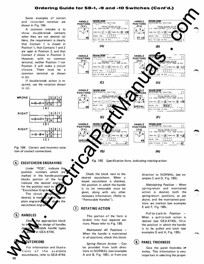
O rd e ri n g G u i d e for S B-t , -9 a n d -to S vvitch es (Co nt•d.)
Some examples of correct a n d i n c o r rect notation are shown in Fig . 1 84.
A common mistake is to s h o w d o uble-break contacts when they are not desired. (a ) Here, the requirement is clearly that Contact 1 is closed in Position 1 , that Contacts 1 and 2 are open in Posit ion 2, and that Contact 2 closes in Position 3. However, with no common termina l , neither Position 1 nor Position 3 wi l l make a circuit c l o sure. There must be a common term inal as shown in (b ) .
I f double-break action i s requ ired, use the notation shown in (c ) .
WRONG I�H�I�I:I 2H ( A l
RIGHT 1 ��� 1�1:1 2H ( 8 )
RIGHT I �H� I� I�I 2 1 ' 1 ( c )
Fig. 184. Correct and incorrect notation of contact connections.
@ ESC UTCHEO N EN G RAVI NG
U nder "POS", indicate the position numbers which are marked in the handle-position blocks portion of the form . I nd icate the desi red engraving for the position next to it under "Escutcheon E ngraving".
The circuit designation, if desired, is marked in the circuit plate engraving block above the escutcheon engraving.
® HAN D L ES
Check the appropriate block to indicate the design of handles desired. Avai lable hand le types are shown in G EA-4746.
® ESCUTCHEONS
48
For information and i l lustrat i o n s o f t h e a v a i l a b l e escutcheons, refer to GEA-4746.
HANDLE POSITIONS
( F.V.)
E HAN DLE
PO SITIONS (F.V.)
EJ HANDLE
POSITIONS ( F.V.)
� HANDLE
POSITIONS (F.V.)
1�4
SPECIAL
ROTATING ACTION MAINTAINED All POS I T I ONS 0
SPR I NG RETURN ACT I ON S . R.. FROM CCW P.OS . : s .f\ . FROM C'w' POS .
'�"_ P{)s_ � _ro_� l'�o� P{)s
_ � _:o� MAINT. PO$ . D:IIJ PULL TO LOCK IN POS , 0
(A}
ROTATING ACTMHt � M�I �T�I�E� �����0�5- - - - _Q I SPR I NG RETURN ACT I ON ]I
S , R . FROM CCW PO$ . : S . R.. FROM CW POS .
F�M_P..?_S_ � _ro_� lF�O� P..?_S_ g _:op
M:A I NT . POS . D:IIJ PULL TO LOCK IN POS. 0
(C)
ROTATifitG ACTION MA I NTAI NED ALL POS I T I ONS 0
SPR ING RETURN ACT I ON S . f\. FROM CCW POS. : S . R.. !="ROM CW POS .
F�"_P..?_S_ g _ro_ g lF�O� P()S_ � _:o�
MA I NT . POS . � PULL TO LOCK IN PO$. 0
(E) ROTATINC ACTION MAINTAINED ALL POS I T I ONS 0
SPR I NG RETURN ACT I ON S . R. FROM CCW POS. : S . R . FROM CW POS .
F�M_P..?_S_ � _TD_ l!llF�O� P..?_S_ � _:ol!J MA INT . POS . D:IIJ PU�L�;-L�C� �-;0-;.- - � - - -0
(G)
HANDLE POSITIONS
(F.V.) 2, 13/4 1 -...::::Jt.-.-5
37 1/2
HANDLE POSITIONS
( F.V.)
~
HANDLE POSITIONS
( F. V.) 2, 13/4 1 �5
SPECIAL
HANDLE POSITIONS
( F.V.)
�
ROTATIIIIC ACr. MAI NTA I NED ALL POS I T I ONS D
SPR ING RETURN ACT I ON S . R. FROM CCW POS . : s . � . FROM CW POS .
F�"_P�S-[]] _ro_ � lF�O� P()S_ � _:o�
MA I NT . POS . D:IIJ PULL TO LOCK IN POS . 0
(B)
IOTIJlliiC ACTION MA I NTAINED ALL POS I T I ONS 0
SPR I NG RETURN ACT I ON S . FL FROM CCW POS. : S . R FROM CW POS .
F'::'M_P..?_S_ g _ro_ g lF�O� P..?_S_ � _:o_0 MAINT . POS . D:IIJ PULL TO LOCK IN POS . 0
(D)
ROTIONC ACTION MA I NTAI NED ALL POS I T I ONS D
SPR I NG RETURN ACTION S . P.. FROM CCW POS. : S . � . FROM CW POS .
''::'"_P�S
-� _ro_@ lF�O� P()S_ � _:o�
MA I NT . PO$ . � PULL TO LOCK IN POS. D
(F) IOTITINC ACTION MA I NTA I NED ALL POS I T I ONS D
SPR I NG RETURN ACTION S . R . FROM CC\ol POS . : S . F L FROM C W POS .
''::'"_
P..?_s_ � _ro_@ l'�o� P{)s_ � _:o� MA I NT . POS . D:IIJ
(H)
Fig. 185. Specification form, indicating rotating action.
Check the block next to the desired escutcheon. When a keyed escutcheon is checked, the position in which the handle is to be removable must be given, a long with any other necessary information. ( Refer to " R emovable Handles" ) .
([) ROTATING A CTI O N
This portion o f the form is broken into four separate sections. Please refe r to Fig. 1 85.
Maintained All Positions When the handle is maintained in all positions, check this block.
Spring Return Action - Can be provided from both directions to N O RM A L (see examples A and 8, Fig. 1 85 ) . or from one
direction to N OR MA L (see examples C and 0 , F ig. 1 85).
Maintaining Position - When s p r ing-return and maintained action is desired, both the spring-retu rn posit io ns, as per above, and the maintained positions are marked (see examples E and F, Fig. 1 85) .
Pull-to-Lock-In Position When a pu l l -to-lock action is desired (see G EA-4746), fi l l- in the position in wh ich the handle is to be pulled and latch (see examples G and H , F ig. 1 85).
@ PAN E L THI C KN ESS
Give the panel thickness ir? inches. This information is very important in selecting the proper www .
Elec
tricalP
artM
anua
ls . c
om
www . El
ectric
alPar
tMan
uals
. com

Ordering G u i d e for S B -1 , -9 a n d -10 Svvitches (Cont"d.)
shaft and spacers, however it is frequently not specified. If the panel thick ness is not given, the switch wi l l be fu rnished for mounting on panels up to 3/ 1 6-inch thick. Most switches can be furn ished for mounting in panels up to two-inches th ick .
@ COVER (N EMA I )
The switch wi l l be furn ished with an extruded viny l cover wh ich meets N E MA I requ i rements. Switches with one to twelve top te rminals on the fixed-contact support assembly wi l l be furn ished with a sta ndard cover. Switches with 1 3 to 32 top terminals wi l l be furn ished with larger covers to a l low more room for the additional wires.
@ SPE CIAL R EMAR KS
This space is provided for any additional information which may be requ i red in the design of the switch. When GE D-3934, Part 2, is used with Part 1 , a notation should be made to indicate that both parts of the specif ication form have been used.
LATERAL CONTACT ACTI ON (SB-1 0 Switches oaly) Complete this section only
when order ing a Type SB- 1 0 Switch which has both lateral and rotary contacts. To identify the lateral stages, mark a dot in the designated blocks to the far left of the contact arrangement. (Maximu m : four lateral stages, two contacts per stage ) . Note : D o not put an " X " under the handle positions for these contacts. An " X " is used only for the rotary contacts. ( F ig . 1 86A) .
The actio n of the lateral contacts is described in the " Lateral Action" blocks. Refer to F ig . 1 868.
I f you want to prevent rotary act ion in one of the lateral positions (either I N or OUT),
®
ON S B - 10 SWI T C H E S CONTACT ARRANGEMENT MARK LAT . STAGES MARK "X" FOR C L O S E D CONTACT
W I TH A DOT . ( . ) j CONTACTS HANDLE POS I T I ON S (BACK V I EW)
HANDLE END ODD EVEN
� f- -H- I 2
� f- H 3 4
-H- � f- 5 6
� f- � f- 7 8
-n- -H· 9 1 0
( A)
FlU OUT BELOW FOR SB-10
LATERAL ACTION
@ ND ROTAT I ON WHEN I I N l OUT MA I NTA I N I NG I N & OUT S PR I NG RETURN TD I N OUT
PULL PUSH I N PDS . TO CLOSE CONTACTS TD DPEN CONTACTS
( C RO S S OUT THE ACT I ON WH I CH DDES NOT APPLY)
(8 }
OPERATIONS O F SB-10 SWITCHES
One Lateral Stage
Pull to open contacts 1 -2 .Maintaining or spring return in or out
Pull to close contacts 1-2 . . . . . Maintaining or spring return in or out
Two Lateral Stages
Pull to open contacts 1-4 .Maintaining or spring return i n or out
Pull to close contacts 1-4 . .Maintaining or spring return in or out
Pull to open contacts 1-2
and close 3-4 . . . . Maintaining or spring return i n or out
Three Lateral Stages
Pull to open contacts 1·6 . . . . . Maintaining or spring return in
Pull to close contacts 1-6 . . . Maintaining or spring return out
Pull to open contacts 1-4
and close 5-6 . . . Maintaining o r spring return in
Pull to open contacts 1-2
and close 3-6 . . . . Maintaining or spring return out
Four Lateral Stages
Pull to open contacts 1-8 . . . . . . . . Maintaining o r spring return i n
Pull t o close contacts 1-8 Maintaining or spring return out
Pull to open contacts 1-6
and close 7-8 .
Pull to open contacts 1-2
and close 3-8 .
Pull to open contacts 1 -4
and close 5-8 . .
. . . Maintaining or sprmg return 1 n
. . . Maintaining o r spring return out
. . Mainta ining or spring return in or out
Pull to open denotes the same contact action as push to close.
Pull to close denotes the same contact action as push to open.
( C ) Fig. 1 86. Notation for specifying Type SB- 1 0 switch action
cross out the other posit ion. I f you want rotary action in both the I N and OUT positions, cross out the word "NO" and add the designation "&" on the l i ne between the words " I N" and "OUT".
spring-return action when the lateral action is in the N O R M A L ( rotary spring released ) posit ion. The max imum nu mber of lateral contacts that can be provided to open with the lateral spring action is four.
If the handle is to be maintained in both the IN and OUT positions, cross out "Spring Re
turn To I N/OUT" . I f the handle is to spring return to either the IN or OUT position, cross out
the undesi red pos1t 1on and "Mainta in ing I N & OUT".
When rotary action is spring return, you can only have latera l
F i rst select the proper action ( Pu l l or Push) and write in the position in wh ich this acti<�n is to take place, then, wr ite in the contact number with the des i red contact action. Refer to F ig . 1 86C for the l ateral action avai lable. Refer to Fig. 1 87 for examp les.
49 www . El
ectric
alPar
tMan
uals
. com
www . El
ectric
alPar
tMan
uals
. com

I
I
I
50
Ordering Guide lor SB-t , -9 and -t o SlNitches (Cont'd.)
2 3 �
2 3
�
2
w 3
"' "' "' ..1 <( <( .... "' "' "' .... -----------------. � CONTACTS POSITIONS (BACK V IE W ) � HANDLE END 3 2 1 1 1 r 11 • 'o-il�o-tt-.6� FOR 0���7:fi�JAR����EE
0-I J-o<>·Ho ; :X _L_j_ L_ FILL OUT BELOW FOR SB-10
LATERAL ACTION
NO ROTAT I ON WHEN -ttt- I OUT MA I NTA I N I NG ( I N & OUT
PULL I � I I N POS . .a TO CLOSE CONTACTS � -� re SPErl eeu;rAe-,:s-
( C ROSS OUT THE ACT I ON WH I CH DOES NOT APPLY)
"' "' "' -' " .. .... 15 "' .... � CONTACTS POSITIONS (BACK VIEW) . HANDLE END 3 l 2 I I I l I l I I I I I • 1<>1 1-<>0-lf-4 f+ FoRDktmtfio�T :mwsEE
<>1 J-oo-1 1-<> 3 5 X 0-1 1-oo-l f<i 6
FILL OUT BELOW FOR SB-10
LATERAL ACTION
NO ROTAT I ON WH EN ..j,./11- I OUT MA I NTA I N I NG ( I N & OUT
PULL I � I I N POS . .2. TQ 6b96� 68�TA6Ti TO OPEN CONTACTS 1 - 2
-( C ROSS OUT THE ACT I ON WH I CH DOES NOT APPLY)
"' "' -' "' <! ;'! :5•(1) .... � CON TACTS POSITIONS (BACK VIE W ) o HANDLE E ND 4 3 2 I I o I� J-o<>1 rd FOR D1��7#fiO�TWL��E E
• 0-1 1-<><>i fo.t f<>o-j f-fi IX 7<>1 1-<><>1 � :><
FILL OUT BELOW FOR SB-10
LATERAL ACTION
NO ROTAT I ON WHEN I I N � MA I NTA I N i i� G ( I N & OUT)
� PUSH I I N POS . A'- L TO C LOSE CONTACTS 1-2 TO OPEN CONTACTS �- � ( C ROSS OUT THE ACT I ON WH I CH DOES NOT APPLY)
2 I � 3
I 8 2
7 * 6 4
5
1 2 I 2
" � 3 10 <
9 5
8 7 6
"' -� � " " .. .... "' "' .... � CONTACT POSITIONS (BACK V IEW I � HANDLE ENO 3 2 I 1 _l I • 1� 1-<>�1� f+ FOR LATERAL STAGES SEE
DESCRIPTION BELOW . it- i 1- 4 . -n- -I I- 6
7 i I -II- a x 9 i l- i l-
I !'X' lb..i J-oo-1 I I
I
FlU OUT BELOW FOR SB-10 ..-----LATERAL ACTION
�OTAT I ON WHEN � OUT MA I NTA I N I NG ( I N & OUT)
PULL 1 � 1 I N POS . .z. TO CLOSE CONTACTS .3 - ¥ .S-6 TO OPEN CONTACTS 1-2-
( C R03S OUT THE ACT I ON WH I CH DOES NOT M P �.oY)
"' _, !!! : � "' "' .... --� CONTACTS POSITIONS (BACK VIEW ) ; HANDLE END 8 7 6 5J4 3121 1 TIT-• I"" J-oo-lf.J r+ • 3<>-j )-oo-j � 4
50-l � f-0 6 o-1 �
O-l � .lll 9
i,..j �;T2
-mo;\\� tf, .. = ,:,
,
r 'x
- �t--1- -- 1---- '---· --- . -1-1- -
FlU OUT BELOW FOR SB-10
LATFRAL ACTION
NO RO rAT I ON WH EN
-- - -
� OUT
� l NG RETURN TO I I N I � P I ; LL-I�l i N POS . AIL TO CLOSE CONTACTS /-2 _":f - q. T8 QPI£11 6QtiTMlT5
( C ROSS OUT THE ACT I ON WH I CH DOES NOT APP L Y )
"' "' ;;#, � .. .... "' "' ....
POSITIONS-HANDLE NORMALLY � .. CONTACTS ..1 ; HANDLE END 12 I I 10 9 8 7 I 6 5 4 3 1 2 I . 1<>1 1-<>o-lf-i ff >---�f<><>-1� SEE BELOW
� 4
�f-:>-1 C>< :;>< -1-- -I-+-� 8 1'x 'X R X 'X IX
� � 9 :>< X X 1-o--i f<; T2
FlU OUT BELOW FOR SB·IO
LATERAL ACTION
NO ROTAT I ON WHEN I N �
S P R I NG RETURN TO I I N I � PULL I PUSH 1 1 N POS . ALL. TO CLOSE CONTACTS .:J-11 TO OPEN CONTACTS 1-2 ( C ROSS OUT THE ACT I ON WH I CH DOES NOT APPLY
Fig. 1 87. Specification form, indicating lateral action. (SB- 1 0 switches only).
-
www . El
ectric
alPar
tMan
uals
. com
www . El
ectric
alPar
tMan
uals
. com

Ordering Guide for SB-1 , -9 and -10 Switches ( Cont'd ) ��--- ------�-----��-�------��--- --
G E N E R A L . E L E C T R I C
SPECIFICATION FORM�PART I TYPE SB-1, -9 AND - 1 0 SWITCIHS Use GED-3934, Part 2 lor special features Refer to GEA-4746 and GET-61691or dncriPtlve lnforrnalion
�!IRK HAIWU POS i l i OI�S ( f ROtH V I E \/ )
±=� �------ �----� . - � � --�-
-�- --� ---·
- ---- ----
-
�
--- ·------- -
--- - --- �--��-�
(SPECIAL FEATURE f"ORM CED-39J4 PT2 MAY B£ USEO \o/ITH TH I S FORM)
GENERAL ELECTRIC CO. • POWER SYSTEMS MANAGEMENT BUSINESS DEPT. • PHILADELPHIA, PA. 19142
-
------------------------------------------------. G E N E R A L . E L E C T R I C
SPECIFICATION FORM�PART 1 TYPE SB-1, - 9 AND -10 SWITCHES
�::a��o0G3i!�i4a:���
o�:r.ae�=� ':r
td���rlpUve information
MI\RK HAIJQL£ POS I T I OIIS (FRQIIT V I t:\1\
--=�-�� - - ---
( S P E C I A L FEATURE FORM GED-3934 PTZ MA¥ BE USED \o/ITH TH I S FORM)
GENERAL ELECTRIC CO. • POWER SYSTEMS MANAGEMENT BUSINESS DEPT. • PHilADELPHIA, PA. 19142
Fig. 1 88. Example of completed specification form, calling for a 3-stage SB- 1 switch, 3-position, main tained action, pistol grip handle, standard cover, and panel thickness of 1/8 inch
G E N E R A L . E L E C T R I C
SPECIFICATION FORM�PART 1 TYPE SB-1, - 9 AND -10 SWITCHfS Use GED-39S4, Part 2 lor special features Refer to GEA-4746 and QET-61691or dncrlptlve information
CONTACT ARRANGEMENT I:::F;,:::;�1:' I I CONTACTS HIINOL£ POS I T IONS (BAC K V I E II )
���o��E�N
o f/ 7 (p f 4 g Z I I r>l t<'Oj f<> ; ' "'t<'<>l fC l I � H><>I "' 1 1 1" 1-oon� : pi 1-601 f') 6 ��· ,;
" " 1 1- :r 1 1- 1 1- :1 -H- -n- :7 i i- -H- '6 ����
' J ' 25 2 2 7 • 2 2) )0 l ' ) 2
GOTTOM TOP SOTTOH TERM I �AL LOCAl I Orr
HTATitCI IC'hDII - j1 1:IAIIDUS �L POS I T IONS � -� _ - - _ - - - - - - - - - - - - - K�IURlEO
SPRI IIG RtTUR:I ACTION S R . FRQI\�� CII POS OVA.L ' ' F��P�s
_Q _ro_Qlr�o� �s-g _:op IP r sroL G R I P
i'IA. I:H P O S . rr::o=J LEVER
PU�l -T; L-;;C;- � --;0-;- -=-=-=-=----= 0 ROUND
M�RK HllltOL£ POS I T IQijS (fRONT V I [II)
� � � � � � � [;] ""'' , _;'"" [MoPE S£t..£Croii�
ENGRAV ING - --I I ,_ ]-
�-+-- ---------?-� -� �� 7 rt _1-- --�
f-t--- ---
-
-
-�� �-
� STANDARD OR ROUND
D TARGET D 0 - - - - - - -0 ��:��. F�:NOLE 0
REMOV . I N POS._ 0 - - - - ---O
NONE 0
----
IT- CMI (NEMA I) �I
,:'="'c::"'=-.-H="=""'='"=c�>�O-----; IL . P I STOL G R I P 0 5_'_"_"_' ====-- �r----"""77-n,--, � D IPANE L T H I CKNESs�l
1IO ROTATION \o/ME1l
SPRI I IG HTURN TO PVLL PVSH I N P O S . TO C L O S E CONTACTS TO OPEN CONTACTS
(CROSS OUT THE A.CTION \o/HICH DOES NQT I\PPLY )
(SPECIAL FEATURE FORM GEO-J93� PT2 MAY BE USED W I T H T H I S FORM)
GENERAL ELECTRIC CO. • POW�R SYSTEMS MANAGEMENT BUSINESS DEPT. • PHILADELPHIA, PA. 19142
Fig. 190. Example of completed specification form, calling for a 5-stage, 8-position SB- 1 switch with maintained action, knurled handle, and 1/4 inch panel thickness
Fig. 1 89. Example of completed specification form calling for an 8-stage SB- 1 switch, 5-position, spring return action (both directions), oval handle, standard cover, and panel thickness of 1/8 inch
51 www . El
ectric
alPar
tMan
uals
. com
www . El
ectric
alPar
tMan
uals
. com

Ordering Guide tor SB- 1 , -9 and -10 Switches ( Cont'd ) @ SPEC IFY ING OPTI O NA L
FEAT U R ES ( G E D-3934, Part 2) Certain optional features are
avai lable with the SB- 1 , -9 and - 1 0 switches, but not necessar i ly to a l l of them. Determ ine whether the option you requ ire is avai lable with the type of switch you are spec ify ing, and check the appropriate b lock as described below. I nformation on these optional features is contained in G EA-4746. @ L O C K- IN HAN D L E
Specify the position or positions in which the handle is to lock. A l l locks wi l l be furn ished with two GE-75 keys, un less otherwise specified. @ SEPA RATE LY M O U NTED L O C K
S B switches are avai lable with a standard lock and key, or with a Kirk key-interlock system . Two keys are furn ished with each lock. Check the proper block . If K i rk key interlock is checked, fi l l out the co-ordination information. Be sure the panel thickness is given. The switch is furnished with the lock for mounting above the switch, as shown under standard mountings, and identified as Lock No.
1 . Complete the descri ption " Lock No. 1 locks and key is removable in Pos. _ _ _ ." I f mounting the lock above the switch is not feasib le, or when two locks (each lock ing in a d ifferent posit ion) a re required, the locks can be mounted to the right, to the left, or below the switch.
To identify the location, the locks are numbers 2, 3 and 4 under "Specia l Mounting". F i l l i n the lock number in the d es c r i ption below and the position in which each lock is to lock .
Coordination I nformation Required for Kirk I nterlock Scheme
To ensure a designated key change is furnished only to the c u sto m e r a n d e q u i p m e n t assigned, the fol lowing information is requ ired :
1 . U lti mate customer's name and address. A lso the su bstation or bui lding when required .
2. Purchase order of coord inating locks a l ready p laced.
52 I f we are the first to place the
-----G E N E R A L � E L E C T R I C @ SPECIFICATION FORM-PART 2 TYPE SB-1, ·9 AND ·10 SWITCHES
U1e with GE0-3934, Part 1 Refer to GEA-4746 and GET-6169 1or descriptive information ® ( .'-, H- 1 (111 'I ) f1'6') �H- l , 'I O H I 1J f
LOCK I N HANDLE [:i(rANDEM SWITCH I � HANDLE lOCKS AND KEY RE�OYABLE I M POS I TI O N _ _ _
SPEC I A L _
® ��-�RA��:y 1�UNT��K_ STANDARD LOCK �MD KEY 0 K I Rk kEY I N TERLOCk [J ( C OO R D I N A T I O N INFO- ( BELOW) MUST BE
COMPLET£0 '11\t EN k i Rk LOCK I S CHECkED)
PAIIEL THI CKIIESS _
STD. MJUNTI NG SPECI AL MJUNTI NG ·'-\ ' NO . I 110.2 MD- 3
. , 'Gi CD :;;: (J)Ha.�
L O C K M O , ! _ LOCKS A N D KEY REMOVABLE I N PO$.
LOCk NO,_ LOCkS AND KEY REMOVABLE I ll POS.
cOORDI NATION I NFO�ATINi RE(lJ I RED FOR K I RK I NTERLOCK SCHEME
I , ULTIMATE CUSTOMERS NAME &. ADDRESS
2 • PURCHASE ORDER OF COO ROlli ATIIIG LOC� S
J, COORD I N A T I N G I N FO. (�MOWN kEY 110, &. P R I N T } _
V E R T I CALLY MOUNTE D
HORI ZOMTALLY MOUNTED
L I Nk TANDEM (MAX. 75° THROW E I TH E R
0 S l OE O F CEIITER F'OS . )
GEAR TAIIOEM
ADO HAll OLE TO DES I R E D SWITCH AIIO SW, 110 . SW. 110. TO CORRESPOND WI TH SW. 110. OM SF'EC l f i CA T I O II FORM.P�- ( COIITACT ARRG'MT. F O RM ) . CROSS O U T T H E SWITCH WH I CH I S NOT RfQtiiREO. FOR ADD I T I ON A L SWITCHES, USE A SEF'AR.HE SHEET SHOW I N G nt E F'ROPER SWITCH ARRAIIGEMEIH.
( :oH· l OR � l
PULL TO TURN TURN I M F'OS. WHEN Ill
PULL I N F'OS. TO TURN TO POS.
PALL AD I � CONTACTS
[j 0 0 0
0
0 CHECk PROPER BLOCk AIIO COMPLETE R E QtJ I R EO I M FORIUTIOII. WR I TE MOllE WH E R E A P P L I C A B L E .
GENERAL ELECTRIC COMPANY POWER S Y STEMS MANAGEMENT BUSINESS DEPT .
PHILADELPHIA, PA. 1 9142
G E N E R A L fj E L E C T R I C
Fig. 191. Specification form, optional features
order, so state and we wi I I so advise on the purchase order that we wi l l place for the locks.
3. The drawings of any K i rk scheme a lready submitted or a copy of the drawing. I f the key c h a n ge h as a l re a d y been assigned, as on reorders, specify the key change number.
Be sure this information is complete and correct when placi ng the order.
@ TAN D EM SWITCH ES
When a switch with more than 1 6 stages is requ ired, two o r m o r e switches can be assembled in tandem, operating with one handle. The switches a r e n o r m a l l y m o u n t ed horizonta l ly , but can a lso be furn ished vertica l ly mounted . A l ink mechanism is normal ly furn ished when the throw on either side of the center position does not exceed 75 degrees. A gear me chanism is used when the throw exceeds 75 degrees. Show the location of the switches and handle on the sketch provided for up to four switches in t a n d e m . T he corresponding
switch numbers on the sketch should a lso be on the contactarrangement specification form . Draw in the handle to show its location, or specify the switch number on which the handle w i l l be mounted. When more than four switches, or a different arrangement, is required, use a separate sheet showing the proper switch arrangement.
@ PUL L-TO-T U R N
I f the handle is t o turn in the I N p o s it ion, i nd icate what positions or positions; i f it is not to turn in the I N position, write " none" . F i l l in the position the handle wi l l be pul led in, and s t a te to what position or positions you wi l l be turning to.
@ PAL L A D I U M CONTACTS Check this block if required .
Pal ladium contacts are ava i lable for temperature-meter switches ( s e e ' ' Te m pe r a t u re- m eter Switches") . I f for a special application where some of the contacts are pal lad ium, but not a l l , specify requirement in th is block or on the contact arrangement. www .
Elec
tricalP
artM
anua
ls . c
om
www . El
ectric
alPar
tMan
uals
. com

G E N E R A L tj E L E C T R I C
SPECIFICATION FORM TYPE SBM SWITCHES Refer to GEA-4746 and GET-6169 for descriptive information
(6-8) 9 I() I I 12 13 14 15 16 17 18 1 1 l o l 4 1 1 1 1 1 1 n n n Ill n
(19 25)
STAGES sroPSIPNLTHK.!sDPS!sHAF'TPos.IJMPRs;/RT 1 ! I I I I CATALOG NO.
L-----FOR FACTORY USE ONLY'---_J
I
A I I MAl NT. y S.R. FROM I S.R. FROM PULL
ALL c.c.w. I c.w. POS. TO I I 0 POSITIONS POSITIONS I POSITIONS W ITH LOCK N I SPR. REt I
I MAINTAINtD - - SPRING- RETURN- - -
37 n KNURLED = K : A
H OVAL = V 1 B � PISTOL GRIP= P I C D LEVER = L I L ROUND = : D E NONE = N I t S I
TO MATCH SB-1 -
38 D � I
STANDARD= S I TARGET = T : y NONE = N 1 (SPECIAL) = P I c
� I KEYED = R I (FOR REM. HDL.) I
N 1
39 40 41 42 43 I I I I I I
ESCUTCHEON KEYWAYS
SSM SWITCH OPERATING REQUIREMENT TABLE
- - - - - -I (44 -51) I
CONTACTS (6 -8) 000 EVEN
l 1 Joj 5 1 (9 -16)
2 I
(6-8)
1 1 1 0 1 6
$-8)
I I IO I 7
01 10 Oi 10 (17-24) (25 32)
3 4 01 ID �10 (33-40
(4 1 -48)
� 10 �!8 (49-56 (57-64)
1 8 01,r 01 10
65 - 72) (9-16)
9 10 Ol iO � 10 (1 7-
(25 32) I I • 1 2 01 fO Ol iO
(33- 40) (41 48)
13 14 01�_� 10 (57-64)
1 5 16 Oj 10 Ol iO ·c65 -72l
2 3 4 5 6 7 8 9 1 0 I I 1 2 1 3 1 4 1 5 1 6
(9 - 16) 18 1 7 1 7 Ol iO Oj 10 (17 -24)
(25 32l 1 9 20 Ol fO � lo ' <33 -40)
1 8 1 9 �0
MARK INTERMEDIATE POS. � I
POSITIONS 8 7 6 5 4 3 2 I
�n�� l l l 8 l 7 1 6 l 5 l 4 1 3 l 2 1 1 1 TOP ' L STOP LOCATIONS -1
TERMINAL LOCATION
USE ONLY WHEN � SLI P CONTACTS ARE REQUI RED �
13 FROM 1- STANDARD ESC. TARGET ESC. 5 4 2 I z 4 2 8
I
A 2 04
2 I 3
4 '---'----'
5 6 7
S (6-8) POS. ESCUTCHEON ENGRAVING
����-+-+� � 9 16 T I I I I I I 9 I - - - - - - - -
f--+---+-+---1--+--+-� 1 7-24 I I I I I I I 1 0 I I
1 2 1 3
��� I I I I I I I 2 - - - - - - - -3:r40 I I I I I I I 41-48 I I I I I I I
3 - - - - - - - -ks-56 I I I I I I I 5H4 I I I I I I I
1 4 4 - - - - - - - -1-+---+-----+--+-�-+-� C6-8l 65-72 I I I I I I I "--+--+--+--+--+---+-1-5jl!l.!l.!. 9 16 I I I I I I I
1----+---+---+-�-+---+-l�6 1 7�24 -
I -
I -
1 -
I -
I -
I -
l-
1 7 12s-� 1 I I I I I I f--+--+-+---+--+--+-� 6 - - - - - - - -l--�+--+--+--+-+l---j8 /:3:r4o I I I I I I J
41 -48 l I I l I I I 1 9 20
r 61 5 r 4 1 1 3 1 2 1 1 T f STOP LOCATIONS l
7 - - - - - - - -/49-56 I I I I I I I 57-64 I I I I I I I 8 - - - - - - - -165-72 I I I I I I I
(6 -Sl \9J CK'T. DESIGNATION ENGRAVING, 22 LETTERS MAX. �ol (MAX. 2 LINES, 8 LETTERS PER L INE_)
! 1 I o I a l l I I I I I I I I I I ! I I I I I I I I I I I (31)
(80) I I I I I I I l � (9) � =I =� =====================1 =1 ======================
(80) I I I I I I I I
GENERAL ELECTRIC CO., POWER SYSTEMS MANAGEMENT BUSINESS DEPT., 6901 ELMWOOD AVE., PHILADELPHIA, PA. 1 9142 GE0-39338 53
www . El
ectric
alPar
tMan
uals
. com
www . El
ectric
alPar
tMan
uals
. com

54
G E N E R A L fl E L E C T R I C
SPECIFICATION FORM-PART 1 TYPE SB-1 , -9 AND -10 SWITCHES Use GED-3934, Part 2 for special features Refer to GEA-4746 and GET-6169 for descriptive information
MARK HAN D L E PO S I T I ON S ( F RONT V I EW) ON S B - 1 0 S W I T C H E S MA R K LAT . STAG E S W I TH A DOT . ( . )
l CONTACTS HAN D L E E N D O D D E V E N
� r- � r- I
2
� f- 1 � 3 4
-H- � f- 5 6
CONTACT ARRAN G E MENT MAR K "X" FOR C LO S E O CONTACT
HANDLE POS I T I ON S ( BAC K V I E W) C?J � � � � � � �
� � � � 7 8
-H- -H- 9 1 0
� � � r- I I
1 2
� f- � � 1 3 1 4
-n- � f- 1 5 1 6
-i f- -i f- 1 7 1 8
� f- . � f- 1 9 20
� f- -i f- 2 1 2 2
--i f- � r- 2 3 2 4
-i f- � f- 2 5 2 6
-i f- -i f- 2 7 2 !l
-i f- -i f- 29 30
-i f- -i f- 3 1 3 2
BOTTOM TOP BOTTOM T E RM I NAL LO CAT I ON
ROTATING ACTION
MA I IHA I N E D A L L POS I T I ON S D - - - - - - - - - - - - - - - - - -SP R I N G R U U RiJ ACT I ON
S . R. F ROf-1 CCW POS . I S . R . FROM CW POS . I
F R0�1 Pos D To D l F ROM POS D roD �-- - - - - - - - - � - - - - - - - -
11A I NT . P OS . I I I I I t- - - - - - - - - - -P U L L TO L O C K I N POS .
FILL OUT BELOW FOR SB-10
LATERAL ACTION
IW ROT AT I ON WH E N I I N I OUT MA I NTA I N I N G ( I N & O U T ) S P R I IJ G R E T U RN TO I I N 1 OUT P U L L I P U S H I I N POS . TO C L O S E C ONTAC T S TO O P E N C ONTACT S
( C RO S S OUT THE ACT I ON WH I CH D O E S NOT APP L Y )
D
IIANOLES --KrW R L E D D OVAL D P I S T O L G R I P D L E V E R D ROUND 0 RAD I AL D L . P I STOL G R I P 0 N O N E D S P E C I AL REMARKS
C I RC U I T PLATE ' E NGRAV I NG POS . E S C UT C H E OI� E N G RA V I N G
ESCUTCHEON
STANDARD D OR ROUND
TARGET D 1- - - - - - - -K E Y E D FOR REMOV . HAN DLE D REMOV . I N POS . _
1- - - - - - - - -
NONE D SP E C I AL
I STAJIMRD COVER
I PAN E L T H I C K N E S S
{ S P E C I AL FEATURE FORM G E D - 39 3 4 PT2 MAY BE U S E D W I T H TH I S FORM)
(NEMA I ) � �
I
GENER AL ELECTRIC CO. • POWER SYSTEMS MANAGEM ENT BUSINESS DEPT. • PHILADELPHIA, PA. 19142 GED-3934B Part 1
-
www . El
ectric
alPar
tMan
uals
. com
www . El
ectric
alPar
tMan
uals
. com

SPECIFICATION FORM-PART 2 G E N E R A L �� E L E C T R I C
TYPE SB-1 I -9 AND - 10 SWITCHES Use with GED-3934, Part 1 Refer to GEA-4746 and GET-6169 for descriptive information
( SH- 1 OR CJ ) LCCK I N HANDLE 0
HAN DLE LOC K S AN D K EY REMO V A BL E I N PO S I T I ON _ _ _ _
SPEC I A L _ _ _ _ _ _ _ _ _ _ _ _ _ _ _ _ _ _ _ _ _ _ _ _
( SB- 1 . 9 OR 10 J
SEPARATELY �UNTED LOCK
STAN DAR D . LOCK AN D K EY D K I RK K EY I N TERLOCK c=) ( COO RD I N AT I ON I N FO. ( BELOW) MU ST BE
COMPLETED WH EN K I RK LOCK i S CH ECK ED )
P AN E L TH I CKN ESS _ __ _ _ _ _ _ _ _ _ _ _
STD. MJUN T I NG
CJ) NO. I
SPEC I AL MOUNT I NG
NO. 2 N O . 3
CD � CD W N O . �
0
LOCK NO. _ l _ LOCK S AN D KEY REMOV ABLE I N POS. _ _ _
LOCK NO. _ _ _ LOC K S KN D K EY REMO VABLE I N POS. _ _ _ _
COORD I-NAT I ON TNF0�1AfiON REQJ IRED -
- - - - -
FOR K I RK I NTERLOCK SCH �E
I . U L T I MATE CU S TOM ERS N AME & ADDRESS _ _ _ _ __ _ _ _
( SB- l . 9 OR 1 0 )
TAN OEM SW I TCH
V ER T I CALLY MOUNTED
HOR I ZON TAL LY MOUN TED
L I NK TAN DEM ( MAX. 7 5° TH ROW E I TH E R S I DE O F CENTE R POS. )
G EAR TAN D EM
ADD HANDLE TO D E S I R E D SWI TCH AND SW. NO. SW. NO. TO CO R R E SPON D W I TH SW. N O . ON
S P E C I F I CA T I ON FORM ..P-::.1 _ ( CON TACT A R R G 1 MT. FORM ) . C RO S S OUT THE SWI TCH WH I CH I S NOT RfQU I R EO. FOR ADD I TI ON A L SWI TCH ES, USE A SEPARATE SH E E T SHOW I N G TH E P ROPE R SWI TCH A R R ANGEM EN T.
( SB- 1 OR 9 ) PULL TO TURN
TU RN I N PO S. _ _ _ _ _ _ _ _ _ _ W H E N I N
D D D 0 0
0 PULL I N POS. _ _ _ _ _ _ _ _ _ TO TURN TO PO S. _ _ _ _
2 . PURCH ASE ORDER OF COO R D I N ATI N G LOC K S _ _ _ _ _ _
3 . COORD I N A T I N G I N FO. ( KN OWN K EY NO. & PR I N T }_ _ _ _
( SB- 1 , 9 OR 1 0 ) PALLAD I UM CONTACTS
G E D - 3 9 3 4 B Part 2
CHECK PROP E R BLOCK AN D COMPL ETE REQU I R E D I N FORMA T I ON . WR I TE NON E WH E R E APPL I CABLE.
G E N ERAL ELECT R I C CO M P A N Y P O W ER SYSTEMS M A N A G E M E NT B U SI N ES S D EPT .
P HILADELPHIA, PA. 1 91 4 2
G E N E R A L fj E L E C T R I C
D
55 www . El
ectric
alPar
tMan
uals
. com
www . El
ectric
alPar
tMan
uals
. com

FIELD MODIFICATION INSTRUCTIONS FOR THE TYPE SBM CONTROL SlNITCH
CASE I-INSPECTING SWITCH O N LY
When the SBM switch is ta ken apart for inspect ion pu rposes on ly and is to be reassemb led without modif ications, fol l ow th i s seq uence :
1 . Turn handle t o vertical ( 1 2 o 'clock posit io n ) .
2 . R emove handle and mounting screws.
3. R emove screws holding the front p late of posit ion ing cham ber .
4 . R emove adj u stable stops, noting rel ati on of the punch mark o n the o perating shaft . Th is punch mark shou ld be pointing towards the 90° ccw position (9 o 'clock location ) .
5 . R emove the sto p spacers and posit ioning whee l . The ba lance of the parts in the front part of the chamber sh o u ld be left i n tact * .
6 . U se a 5/ 1 6 " wrench t o loosen the tie bolts in the rear of the switch . Back off the bo lts on ly as far as n ecessary to loosen the posi t ion ing chamber from the balance of the assembly and remove chamber.
7 . Push tie bolts back up agai n st the rear barrier to keep the stages i ntact.
8. Turn o perat ing sh aft so th at pu nch mark is not facing the bottom vertical (6 o'clock) posit ion .
9 . Remove the f irst stage front barrier cover.
1 0 . Read the fo l lowing before re moving cams.
Note: Each stage houses two double-surface cams. The first controls the action of the even number contact while the second cam controls the odd number contact. One cam is distinguished from another by a number (1 to 22) on one surface of the cam.
*On a con trol switch with a spring re
turn feature there are no parts in the front
half o f the positioning chamber except the
stop cams and a thick spacer. The rear half
o f this chamber houses the torsion spring.
When the chamber is removed from the as
sembly the spring actuator, torsion spring
and spacer will be up against the fran t bar
rier plate of the first stage of con tacts. These parts should be removed and replaced
in order. The balance of the steps for dis
man tling and reassembly remain the same.
56
With this number the following letters appear in 45° intervals 8-C-D-E-F-G-H. On the reverse side of the cam there are eight letters in 4b intervals as follows: J-K-L-M-N-P-R-S.
1 1 . N ote the number of the cams as they are removed, jott ing down the letter on the cam wh ich passes over the pu nch mark on the o perat ing sh aft . Th e cam must be reassembled on the operating shaft w ith respect to th is letter and punch mark i n order t o obtain t h e same contact seq uence.
1 2 . The ba lance of parts i n any stage m ay be removed in any seq uence .
1 3. U n less the o perati n g shaft is to be changed there is no need to remove the tie bolts when fol lowing any of the above steps. These bolts should be k ept snug agai nst the rear barr ier to insu re proper reassem bly of the switch .
14. When reassembl ing fo l low a l l steps in reverse order.
CASE I I -CHAN G I N G CONTACT SE QUENCE
I f the S B M switch i s t o b e taken apart and the contact seq uence modif ied, fol low the steps o utl i ned in Case I . Omit step # 1 1 s ince the cam locations in most cases w i l l have to be changed to obta i n the necessary seq uence . The fo l lowing are i nst ructions necessary to select the n ew cams.
SET UP T HE F O L L OWI N G TABLE
I B M CO D E 1 2 4 1 2 4 1 2 CAM
POS I T I O N S 8 7 6 5 4 3 2 1 CODE
CON TACT #1 X X X X X X 2 7 3 #2 X X 0 6 0 #3 X X X X 3 0 5 #4 X 1 0 0
The fi rst l i n e indicates the SBM cod ing system . The second l ine corresponds to the e ight handle posit ions of the switch with posit ion #1 at the 9 o'clock l ocatio n and the balance of the positions in 45° intervals moving in a clockw ise rotatiQ n . Th e contact d ia gram shown above i n dicates a sequence for a two-stage fou r-contact
switch . R eferring to the segment on the right, contact #1 is shown closed in position #1 . D i rect ly above posit ion #1 i s the I B M Code 2. P l ace this n u m ber in the extreme left colu m n of the section marked Cam Code . In the next segment contact #1 is closed in posit ions 3 , 4 , 5; d i rectly above these posit ions a re the code n u m ber 1 , 2 and 4. Thei r sum is the second digit of the --., cam code . I n th e th i rd segment con-tact #1 is c losed in posit ions 7 & 8, the code n u m bers above th ese two posit ions are 1 & 2 . Their sum is the th ird dig it of the code n u m ber. It can be seen that contact #2 i s only closed in the second segment u nder positions 3 & 4 whose code is 2 & 4. There is no contact sequence in segments one a nd three so the fi rst and l ast d ig it of the contact's code n u mber w i l l be zero . Th e m idd le d ig it w i l l be 6 , the sum of codes 2 & 4 . The same method i s u sed to f ind the cam code for contact 3 & 4.
Now that the cam codes h ave been -� der ived , refer to the attached cam code sheets. One of these sheets is for the l eft-hand even n u mber contacts and the other for the r ight-hand odd n u m ber contacts.
The cam code for contact #3 is 305 . R efer to the Cam Code sheet for odd n umber contacts. Beside n u m ber 305 on cam and position is the l i st ing 1 4G . This means cam #14 should be placed on the switch operating sh aft so that the letter "G" passes over the punch mark . Th is w i l l provide the sequence for contact #3 as shown in the diagram.
F o r contact #4 the cam code i s 1 00 . Beside th is n u m ber o n the sheet '"""\. for left-hand even n u m ber co ntacts is the l i st ing 1 B . Cam #1 sh o u ld be placed on the o perat ing sh aft so that the letter " B " passes over the punch mark on the shaft. Th is w i l l provide the sequ ence for contact #4 as shown in the d iagram . The sa me proced u re shou ld be fo l lowed fo r con tacts #1 and 2 whose codes are 273 and 060 and whose l i st i ngs are 5F and 2C .
The switch can be n ow be reas- ·"'"""' sem bled by revers ing the steps l isted in Case I . Care m ust be exercised to make sure that the punch mark is returned to 9 o'clock posit ion before placing the stop cams. Th is automatica l ly www .
Elec
tricalP
artM
anua
ls . c
om
www . El
ectric
alPar
tMan
uals
. com

places the h andles in the 12 o'clock posit ion and insures a correct seq uence for the contacts.
tact seq uence. When a sl i p cam is requ ired to actu ate a sequence as contact #1 or #2 in the ta ble below,
22 K i s the cam code. When the se quence is to be as shown fo r contact #3, the cam code is 22D .
code sheets. R equests for ch anges of this type shou ld be referred back to the factory.
4 3 F R OM 2 One cam n ot covered by this se
quence is the s l ip cam for· breaker contro l switches.
Th is cam is n u m ber 22 and can on l y be mounted o n the operating shaft i n two locations for proper con-
Switches which req u ire a makebefore-break ( overlapping) seq uence req u i re specia l cams, o n ly when th ree i ntermed iate steps a re requ ired between each handle posit ion . They cannot be mod ified therefore b y using the
1
2
3 X
4 2
X X
X X
X
SBM SWITCH CAM CODE (ODD NUMBER CONTACTS)
c Contact Cam Contact Cam Contact Cam Contact Cam Contact Cam Contact Cam Contact Cam Contact Cam
Sequence & Sequence & Sequence & Sequence & Sequence & Sequence & Sequence & Sequence & Number Position Number Position Number Position Number Position Number Position Number Pos1t1on Number Position Number Position
- - - --- -- - - - - - - - - -- ---- - -- ----
000 040 l l 1 00 l K 1 40 2L 200 l J 240 3L 300 2K 340 6L
001 1 s 041 4L 1 0 1 3 K 1 4 1 7 L 2 0 1 2 J 241 l OJ 301 6K 341 1 3H
002 1 R 042 5L 1 02 4K 1 42 8L 202 3J 242 l l l 302 7K 342 1 4H
003 25 043 95 1 03 l OS 1 43 1 5H 203 6J 243 21 H 303 1 3G 343 6H
004 1 p 044 4P 1 04 5K 1 44 9L 204 4J 244 1 2 L 304 8K 344 1 5 L
005 35 045 1 25 1 05 1 1 K 1 45 20E 205 7J 245 1 6F 305 1 4G 345 7H
006 2R 046 8R 1 06 9R 1 46 1 8 E 206 l OR 246 1 7 F 306 1 5G 346 8H
007 65 047 1 5 5 1 07 2 1 G 1 47 9H 207 1 3 F 247 l OH 307 6G 347 2H
----- --- --- ---- - ---- - - - -------
0 1 0 I N 050 3N 1 1 0 4N 1 50 l OL 2 1 0 5J 250 1 1 N 3 1 0 9K 350 2 1 8
0 1 1 45 051 1 2N 1 1 1 1 2K 1 5 1 1 6H 2 1 1 BJ 251 1 7H 3 1 1 1 5K 3 5 1 1 08
0 1 2 3� 052 1 1 R 1 1 2 1 2 R 1 52 1 78 2 1 2 l l J 252 1 9 F 3 1 2 200 352 1 1 H
0 1 3 75 053 208 1 1 3 1 6E 1 53 1 2H 2 1 3 1 4 F 253 1 1 F 3 1 3 7G 353 3H
0 1 4 2 P 054 7P 1 1 4 8 P 1 54 1 5C 2 1 4 9 P 254 20H 3 1 4 1 8H 354 9C
0 1 5 l O P 055 1 6C 1 1 5 1 7 E 1 55 1 2C 2 1 5 1 5 F 255 1 2 F 3 1 5 8 G 355 4H
0 1 6 6R 056 1 4 0 1 1 6 1 5 R 1 56 80 2 1 6 2 1 F 256 1 1 0 3 1 6 9G 356 5H
0 1 7 1 3E 057 7E 1 1 7 l OG 1 57 4E 2 1 7 6 F 257 3F 3 1 7 2G 357 l H
---
020 1 M 060 2M 1 20 3M 1 60 6M 220 4M 260 7M 320 l OK 360 1 3A
021 5M 061 BM 1 2 1 l i M 1 6 1 1 4A 2 2 1 9J 261 1 5A 3 2 1 2 1 A 3 6 1 6A
022 4 R 062 9M 1 2 2 1 2M 1 62 1 5M 222 1 2 J 262 20F 322 1 6G 362 7A
023 BS 063 1 8 F 1 2 3 1 7G 1 63 BA 223 1 5J 263 9A 323 l OA 363 2A
024 3 P 064 I OM 1 24 I I P 1 64 2 1 C 224 1 2 P 264 1 6A 324 1 7A 364 I CC
025 1 1 5 065 1 7C 1 25 1 9 E 1 65 1 1 A 225 20C 265 1 2 A 325 1 1 G 365 3A
026 7R 066 1 50 1 26 20A 1 66 90 226 1 60 266 1 2 0 326 1 2 G 366 4A
027 1 4 E 067 BE 1 27 l i E 1 67 S E 227 7F 267 4 F 327 3G 367 l A
-- ----"---- ------- - -- - --- -----
030 2N 070 6N 1 30 7N 1 70 I J 8 230 BN 270 1 4 8 330 1 5 8 370 68
031 9N 071 I SN 1 3 1 20G 1 7 1 7 8 2 3 1 l BG 271 B8 3 3 1 98 371 2 8
032 I ON 072 2 1 0 1 32 1 6 8 1 72 1 00 232 1 70 272 1 1 8 332 1 2 8 372 38
033 1 5 E 073 9E 1 33 1 2 E 1 73 48 233 B F 273 S F 333 4G 373 1 8
034 6 P 074 1 3 C 1 34 1 4 C 1 74 6C 234 1 5 P 274 7C 334 8C 374 2C
035 2 1 E 075 I CE 1 35 I I C 1 75 3C 235 9F 275 4C 335 SG 375 I C
036 1 30 076 60 1 36 70 1 76 20 236 l Of 276 30 336 40 376 1 0
037 6E 077 2E 1 37 3E 1 77 1 E 237 2F 277 l f 337 I G 377
NOTE, When cam code specifies the use of cam 1 A, 2A, JA, etc., the number on the cam should pass over the punch mark on the operation skoft since the leHer "A" does not appear on the cams.
SBM SWITCH CAM CODE (EVEN NUMBER CONTACTS)
Contact Cam Contact Cam Contact Cam Contact Cam Contact Cam Contact Cam Contact Cam Contact Cam Sequence Sequence & Sequence & Sequence & Sequence & Sequence & Sequence & Sequence & Number Position Number Position Number Position Number PDsition Number Position Number Position Number Position Number Position
000 040 l C 1 00 1 B 1 40 2B 200 l A 240 3A 300 2A 340 6A
001 l H 041 4H 1 0 1 3 H 1 4 1 l OB 201 2H 241 7H 301 6H 341 1 3H 002 l G 042 sc 1 02 4G U2 98 202 3G 242 1 1 G 302 l OA 342 2 1 A
003 2G 043 BG 1 03 7G 1 43 l SK 203 6G 243 1 4 G 303 1 3G 343 6K 004 1 F 0 .. K 1 04 58 1 4 4 8 8 204 4f 244 1 2A 304 9A 344 1 5A
005 3 F 045 1 2 F 1 05 l l f 1 4 5 1 7H 205 l OH 145 1 6f 305 2 1 H 345 1 0J
006 2 F 046 9f 1 06 Bf 146 1 BC 206 7f 246 20C 306 I SJ 346 9J
007 6F 047 I S F 1 07 1 4 F 1 47 BJ 207 1 3 f 247 7J 307 6J 347 2J
0 1 0 1 E 050 3C 1 1 0 48 1 50 78 2 1 0 SA 250 I I A 3 1 0 BA 350 1 4 A
0 1 1 4E 051 1 2C 1 1 1 1 2H 1 5 1 1 6H 2 1 1 9H 2 5 1 20E 3 1 1 1 5H 351 7 L 0 1 2 3E 052 1 1 C 1 1 2 1 2 E 1 52 20G 2 1 2 l i E 252 1 9A 3 1 2 1 7G 352 1 1 M
0 1 3 l OG 053 1 7E 1 1 3 1 6E 1 5 3 1 2K 2 1 3 2 1 G 253 I l K 3 1 3 1 05 353 3K ou 2E 054 l OE I U 9E 1 54 1 5N 2 U B E 254 1 7C 3 1 4 1 8 8 354 8M 0 1 5 7 E 055 1 6C 1 1 5 208 1 55 1 2N 2 1 5 1 55 255 1 2 5 3 1 5 95 355 4L 0 1 6 6E 056 21 E 1 1 6 1 5E 1 56 9N 2 1 6 1 4 E 256 1 1 5 3 1 6 BS 356 55 0 1 7 1 3 E 057 l O P 1 1 7 75 1 57 45 2 1 7 65 257 3 5 3 1 7 2 5 357 I 5
020 1 0 060 2C 1 20 38 1 60 68 220 4A 260 I CC 320 7A 360 1 3A 0 2 1 50 061 9C 1 2 1 1 1 H 1 6 1 2 1 & 221 BH 261 1 5 L 3 2 1 1 4H 361 6L 022 40 062 8C 1 22 1 2 8 1 62 1 5 8 222 1 2 G 262 1 7A 322 1 6G 362 l OK 023 9G 063 1 80 1 23 200 1 63 9K 223 1 5G 263 BK 323 7K 363 2K 024 30 064 7C 1 24 1 1 8 1 64 1 4 8 224 1 2 0 264 1 6A 324 20F 364 7M 025 1 1 0 065 20H 1 25 1 9 8 1 65 l i N 225 1 7F 265 1 2 L 325 l l l 365 3L 026 l OF 066 1 5 P 1 26 1 70 1 66 BN 226 1 60 266 1 2 P 326 1 25 366 4M 027 2 1 F 067 9P 1 27 l l J 1 67 SN 227 l OR 267 4J 327 3J 367 l J
- -
030 20 070 6C 1 30 1 00 1 70 1 3 8 230 90 270 2 1 C 330 1 5M 370 6M 03 1 BD 071 1 5C 1 3 1 1 78 1 7 1 I OL 231 l BA 271 9L 331 B L 3 7 1 2L 032 70 072 1 4C I 1 32 1 6 8 1 72 7N 232 20A 272 1 1 p 332 1 2M 372 3M 033 1 5 R 073 BP 1 33 1 2 R 1 73 4N 233 9R 273 5P 333 4K 373 l K 034 60 074 1 3C 1 34 2 1 0 1 74 6N 234 1 50 274 I OM 334 9M 374 2M 035 1 40 075 7P I 1 35 1 1 R 1 75 3N 235 BR 275 4P 335 SR 375 1 L 036 1 30 076 6P I 1 36 I ON 1 76 2N 236 7R 276 3 P 336 4 R 376 1 M 037 6R 077 2P i 1 37 3 R 1 77 I N 237 2R 277 I P 337 1 R 377
------------------------ --- ---
NOTE, When cam code specifies the use of cam 1 A, 2A, 3A, etc., the number on the cam should pass over the punch mark on the operation shaft since the letter "A" does not appear on the cams.
-- - -- ---
W H E N USE D
1
22 K
X 22 K
22 D
57
www . El
ectric
alPar
tMan
uals
. com
www . El
ectric
alPar
tMan
uals
. com

1 6S B 1 o r
1 6SB9
Design
Type
Common
To All
S B- 1 & 9
Switches
T H E G U I D E B E LOW I S F O R U N L I ST E D S W I T C H E S W H I C H A R E N U M B E R E D AT T H E F A C T O R Y .
U S E I T O N LY A S A G U I D E T O I D E N T I F Y CATA L O G N U M B E R S A SS I G N E D B Y T H E F A CT O R Y .
1 &S B 1 or 9 N o m e n c latu re G u i d e t o U n l isted Svvitc h es
BAS I C SW I TCH *
2nd Basic 3 or 4 Digit N o .
CODE L E TTE R S * *
2nd Code 3rd Code
Letter Letter
SPEC I F I E D O N L Y W H E R E SPE C I A L F EATU R ES A R E R E QU I R E D . * *
1 st Basic Letter Cont. Develop· Style Spring R et . 1 st Code 4th Code
Letter- Type of ment. 1 st Code Escutcheon or N u mber Letter
No. of Stationary Factory Assign. Letter Specify M a i n t . � S'tYiT Stages Contacts N o . of Pos. E nclosure E ngraving Contacts Th ick ness Handle
A � 1 A & E - 1 00 � 9, 1 0 , 1 1 A � 2 � 1 /8 D � R o u nd
B � 2 A l l F 1 x ed & 1 2 P a s . Explosion 3 � 3 / 1 6 v ·604 7044- 1
c � 3 Contacts 200 = 2 Pas . Proof+ 4 = 1 /4 K � K n u r led
D � 4 T h u s 300 w � E tc . K -60 7 9 1 20 - 1
E � 5 0-1 f--0--1 1--0 & 3 Pos Watertight+ N u mbers L � Large
F � 6 B, K & F - 900 & Dusttight See Tab l e , Page 6 3 I nd1cate P1stol G r i p
G = 7 A l l F 1 x ed 400 = 4 Pos . p � N u mber o f K -6208 1 3 7 - 1
H � 8 Contacts 500 = 5 P o s . Oil-Fi l l ed+ O ne· P � Smal l
K = 9 T h u s 6 0 0 = 6 Pas. S = S i x t e e n t h s P 1 s t o l G r i p
L = 1 0 0-i r-o 0-i r-o 700 = 7 Pas . Standard of an I n c h K -60460 7 4 - 1
M = 1 1 C & G - 800 = 8 Pas. Cover 99 � N o R � R ad i a l
N = 1 2 A l l F 1 x ed OAOO � Spec i a l L = Panel V -604 7 0 4 3 · 1
p = 1 3 Contacts Large T h i c k ness V = Oval
R � 1 4 T h u s . Cover I n vo l ved K -60460 7 5 - 1
T = 1 5 o-l H f--0 M = Y = Om i t H a nd l e
u = 1 6 D , H & M - Fabricated E = Lever
M i s c . C o m b 1 n a - Metal + v ·62480 3 4 - 1
t 1 o n s of A , B , C , ( Large) W = Watertight+ E . F & G and D-Si otted M-64 1 1 824G-2 S i n g l e Contacts End Cove r + ( 1 /8) E xa m p l e : V1 = Vert. M-64 1 1 824G-3
0-! 1--0-1 1--0 Split (Std.)+ (1 /4)
� 1--1 1--0 . V2 = Vert. c = Corbin � 1-001 f-{) Split ( Lg. ) + Lock
� 1--0-1 H1 � Horiz
1--0-1 f--0 Split (Std.)+
H2 = Horiz
Split ( Lg. ) +
5th Code
Letter --
S 1 } Sequence
S2
S3 Latch•+
A I\ Rig ht""""+
A2
A3 Angle
A4 Drive
R 1 = Ratchet
Mech. for
CW Rot. Onl y +
R2 = Ratchet
Mech. for
CCW Rot. On l y t
P 1 -P 1 2 =
Pul l -to- Lock
H 1 to H 1 6 t
• Bas1c n u mber assi� ned by factory e n g 1 n eers o n l y to iden t 1 fy a spe c 1 a l contact a r rangement
• * S u f f i x added by factory eng1neers t o complete swi t c h to c u s t o m e r ' s spec i f , c a t 1 o n s
+This featu re is no l onger
avail able (obsolete) .
1 S 1 = L a t c h 1 n g 1n CW & CCW posit ions
S2 � W i l l prevent repeated CCW t h row
S3 = W 1 l l prevent repeated CW throw
tP a l l ad i u m contacts a r e avai lab l e ; H 1 d e signates a sing l e -stage s w itch , H2 a t w o-stag e , u p to H 1 6 f o r a
"" . .
l A A 1 = S w i t c h m o u n ted to the l e f t
A 2 = S w 1 t c h m o u n ted t o t h e r i g h t
A 3 � S w i t c h m ou n ted u p
A 4 = S w 1 t c h m oun ted down 1 6 -stage s w itch . """"""'�
58 www . El
ectric
alPar
tMan
uals
. com
www . El
ectric
alPar
tMan
uals
. com

S B-1 or SB-9 SB-1 SB-9 2 n d Form Letter 3rd Form Letter 3 rd Form Letter
c ESCUTCHEON SPRING RETURN AND MAINTAINING SPRING RETURN AND MAINTAINING
Escutcheon Typical Model Throw Code Description Code Description Code Number Handle No.
Handle Removable in Vertical Position Combination of Spring Return Maintaining Except
A 60 1 6 1 64-3 1 6SB 1 C C 1 1 3 5° c w a n d Maintaining Contact A S.R. from 4 5 ° CW to Normal
A - 3 C C 1 8 360° A S.R. from 4 5 ° CW to Normal
B S.R. from 4 5 ° C C W to Normal B -4 C C 2 1 3 5 ° cw
B S.R. from 4 5 ° C C W to Normal B -4 C C 1 9 3 60° c Same as A- See *
c -5 CC3 1 3 5 ° c w c S.R. from 4 5 ° CW to Normal 6 Same as 8 - Se e * (One Extra Sta g e ) D
c -5 C C 1 5 3 60°
D S.R. from 4 5 ° C C W Ia Normal 6 J S.R. from 7 5 ° CW to 4 5 ° CW & from 7 5 ° D -6 CC4 1 3 5° c w
( O n e Extra �lo g e ) C C W t o 4 5 ° C C W D -6 C C 1 1 4 5 ° cw & c c w c
D - 6 CC22 45° C C W E S.R. from 90° CW to Normal *Has 1 Extra Sta g e for Extra Spring D -6 CC27 360°
E -7 CC5 4 5 ° CW F S.R. from 90° C C W to Norm a l
E -7 CC 1 2 75° c w G S.R. from 90° CW to Normal 6 E -7 CC 1 3 4 5 ° cw & ccw E -7 CC20 360° (One Extra Sta g e ) Maintaining E -7 C C 2 5 7 5 ° C C W
H S.R. from 90° C C W to Normal D Ma i nta i n i n g Contact lor a l l 45° Positions M F -8 CC6 45° c w ( O n e Extra Sta ge)
F - 8 C C 1 4 45° CW & C C W K S.R. from 45° CW to Normal & N Ma i nta i n i ng Contact lor al l 30° Positions
F -8 CC24 3 60° (Two Extra Sta ges)
6 K Mainta i n ing Contact far 60° Positions G -9 CC7 45° CW "I" Eng. L S.R. from 4 5 ° C C W to Normal G -9 C C 8 4 5 ° C C W " R" Eng.
(Two Extra Stages) Maintain ing Contact far all 37 Y, 0 Positions G -9 C C 1 7 4 5 ° ccw v G -9 CC26 1 3 5 ° ccw G -9 CC29 4 5 ° c w M Maintaining Contacts L Ma intain ing Contact for a l l 75° Positions G -9 CC2 1 360°
Mainta i n ing Contact for Two Positions 90° E H - 1 0 C C 2 3 3 6 0 °
P u l l T o Lock Apart Arranged V H - 1 0 C C 9 45° CW "I" Eng. c H - 1 0 C C 1 0 45° CCW "R" Eng. p S.R. from 4 5 ° CW & C C W to Normal, F Mainta i n ing Contact lor Four Positions 90° H - 1 0 CC3 1 45° C W
Pull t o Lock in 4 5 ° C C W , Then Turn Apart Arranged + H - 1 0 C C 3 2 4 5 ° ccw
to 7 5 ° C C W & Pull to Lock
J - 2 3 (C 1 8 3 60° X Special R S.R. al l Positions Except When
y - 2 4 C C 1 9 3 60° locked, Pull Ia lock at 7 5 ° CCW
Spring Return
z - 2 5 C C 2 1 3 6.0° s S.R. far a l l Combin ations of 30°, 37 Y2°, 4 5 °,
Handle Removable-90° CCW Spring Return Only
60 , 7 5 °, 90° CW & CCW
K 60 1 6 1 64- 1 1 1 6SB 1 CC 1 1 3 5 ° c w s S.R. from al l Positions to Normal T Same as S-Se e *
K - 1 1 C C 1 8 3 60° S.R. from a l l Positions to NormaiD *Has 1 Extra Sta g e for Extra Spring T
L - 1 2 C C 2 1 3 5° C W , (One Extra Sta ge) l - 1 2 CC 1 9 360°
S.R. from a l l Positions Ia Normal6 Spring Return with Provision far Intermediate u M - 1 3 C C 3 1 3 5 ° c w (Two Extra Stages) Temporary Contact Position at the H a lf M - 1 3 C C 1 5 3 6 0 ° W a y Point.
N - 1 4 C C 1 1 4 5 ° cw & ccw u S-R.-90° CW & CCW Temp. Feel 30 ° & 6 0 ° N - 1 4 CC27 3 60° c N - 1 4 CC4 1 3 5 ° CW Abbreviations w S.R. from 90° CW or C C W or both N - 1 4 CC22 4 5 ° C C W
S.R. = Spring Return y S.R. from 60° CW or C C W or both Fixed Handle cw = Clockwise p 6 0 1 6 1 64-60 Pu l l to lock (Target) CCW = Counterclockwise z S.R. from 7 5 ° CW or C C W or both R 60 1 6 1 64- 1 5 Rou n d s 6 0 1 6 1 64 - 1 Standard Abbreviations T 6402 6 70G * Target Symbols u O m it Escutcheon 6 S.R. = Spring Return v Special Escutcheon = On e Extra Sta g e for
Removable Handle Torsion Spring. cw = Clockwise
w Omit Escutcheon & = Two Extra Stages for C C W = Counterclockwise 00) Speci a l Escutcheon Additional Torsion Springs. C'
* [Nu mber to be assigned.]
59
www . El
ectric
alPar
tMan
uals
. com
www . El
ectric
alPar
tMan
uals
. com