control equipment for the vibratory feeder industry … · · 2014-10-28vbt-6 super tuner...
TRANSCRIPT
The Arthur G. Russell Co., Inc. 750 Clark Ave. P.O. Box 237
Bristol, CT 06011-0237 Phone (860) 583-4109 Fax (860) 583-0686 www.arthurgrussel.com eMail: [email protected]
Operating Instructions
VBT-6 Super Tuner PRO-TOOL
MFS 6050_USA_4_2005
Con
trol E
quip
men
t for
the
Vib
rato
ry F
eede
r Ind
ustry
Operating Instructions VTB-6 Super Tuner
Technical safety instructions for the user This description contains the necessary information for the correct application of the product described below. It is intended for use by technically qualified personal. Qualified personnel are persons who, because of their training, experience and position as well as their knowledge of appropriate standards, regulations, health and safety requirements and working conditions, are authorized to be responsible for the safety of the equipment, at all times, whilst carrying out their normal du-ties and are therefore aware of, and can report, possible hazards (Definition of qualified employees according to IEC 364) Safety Instructions The following instructions are provided for the personal safety of operators and also for the protection of the described product and connected equipment.
Warning!
! Hazardous Voltage Failure to observe can kill, cause serious injury or damage
• Isolate from mains before installation or dismantling work, as well as for fuse changes or post installation
modifications. • Observe the prescribed accident prevention and safety rules for the specific application. • Before putting into operation check if the rated voltage for the unit conforms with the local supply voltage. • Emergency stop devices must be provided for all applications. Operation of the emergency stop must
inhibit any further uncontrolled operation. • The electrical connecting terminals must be covered! • Earth bonding must be tested for integrity after installation. Specified Use The units described herein are electrical controllers for installation in industrial plant. They are designed for controlling vibratory feeders.
1
Operating Instructions VTB-6 Super Tuner
2
Track control
t ON t OFF
Sensor
Feeder ON
OFF
ON
OFF
Soft Start Soft Stop
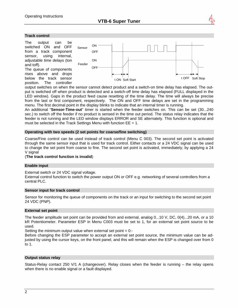
The output can be switched ON and OFF from a track component sensor, using internal, adjustable time delays (ton and toff). The queue of components rises above and drops below the track sensor position. The controller output switches on when the sensor cannot detect product and a switch-on time delay has elapsed. The out-put is switched off when product is detected and a switch-off time delay has elapsed (FULL displayed in the LED window). Gaps in the product feed cause resetting of the time delay. The time will always be precise from the last or first component, respectively. The ON and OFF time delays are set in the programming menu. The first decimal point in the display blinks to indicate that an internal timer is running. An additional “Sensor-Time-out“ timer is started when the feeder switches on. This can be set (30...240 sec.) to switch off the feeder if no product is sensed in the time out period. The status relay indicates that the feeder is not running and the LED window displays ERROR and SE alternately. This function is optional and must be selected in the Track Settings Menu with function EE = 1. Operating with two speeds (2 set points for coarse/fine switching)
Coarse/Fine control can be used instead of track control (Menu C 003). The second set point is activated through the same sensor input that is used for track control. Either contacts or a 24 VDC signal can be used to change the set point from coarse to fine. The second set point is activated, immediately; by applying a 24 V signal (The track control function is invalid) Enable input
External switch or 24 VDC signal voltage. External control function to switch the power output ON or OFF e.g. networking of several controllers from a central PLC. Sensor input for track control
Sensor for monitoring the queue of components on the track or an input for switching to the second set point 24 VDC (PNP). External set point
The feeder amplitude set point can be provided from and external, analog 0...10 V, DC, 0(4)...20 mA, or a 10 kR Potentiometer. Parameter ESP in Menu C003 must be set to 1, for an external set point source to be used. Setting the minimum output value when external set point = 0:- Before changing the ESP parameter to accept an external set point source, the minimum value can be ad-justed by using the cursor keys, on the front panel, and this will remain when the ESP is changed over from 0 to 1. Output status relay
Status-Relay contact 250 V/1 A (changeover). Relay closes when the feeder is running – the relay opens when there is no enable signal or a fault displayed.
Operating Instructions VTB-6 Super Tuner
Air valve output 24 VDC
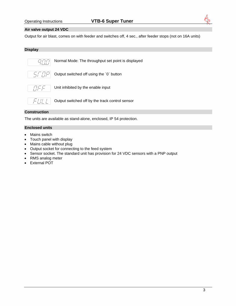
Output for air blast, comes on with feeder and switches off, 4 sec., after feeder stops (not on 16A units) Display
Normal Mode: The throughput set point is displayed Output switched off using the `0` button Unit inhibited by the enable input Output switched off by the track control sensor
Construction
The units are available as stand-alone, enclosed, IP 54 protection. Enclosed units
• Mains switch • Touch panel with display • Mains cable without plug • Output socket for connecting to the feed system • Sensor socket. The standard unit has provision for 24 VDC sensors with a PNP output • RMS analog meter • External POT
3
Operating Instructions VTB-6 Super Tuner
4
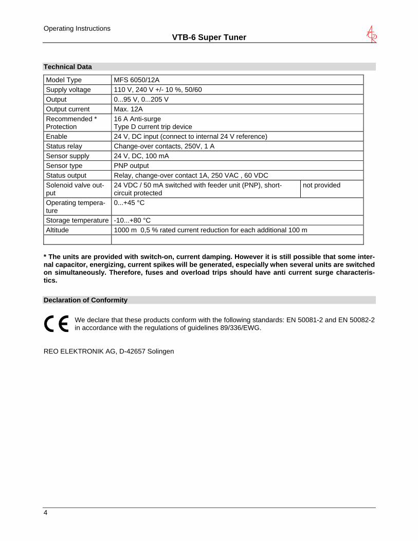
Technical Data
Model Type MFS 6050/12A Supply voltage 110 V, 240 V +/- 10 %, 50/60 Output 0...95 V, 0...205 V Output current Max. 12A Recommended * Protection
16 A Anti-surge Type D current trip device
Enable 24 V, DC input (connect to internal 24 V reference) Status relay Change-over contacts, 250V, 1 A Sensor supply 24 V, DC, 100 mA Sensor type PNP output Status output Relay, change-over contact 1A, 250 VAC , 60 VDC
not provided Solenoid valve out-put
24 VDC / 50 mA switched with feeder unit (PNP), short-circuit protected 0...+45 °C Operating tempera-
ture Storage temperature -10...+80 °C Altitude 1000 m 0,5 % rated current reduction for each additional 100 m
* The units are provided with switch-on, current damping. However it is still possible that some inter-nal capacitor, energizing, current spikes will be generated, especially when several units are switched on simultaneously. Therefore, fuses and overload trips should have anti current surge characteris-tics.
Declaration of Conformity
We declare that these products conform with the following standards: EN 50081-2 and EN 50082-2 in accordance with the regulations of guidelines 89/336/EWG.
REO ELEKTRONIK AG, D-42657 Solingen
Operating Instructions VTB-6 Super Tuner
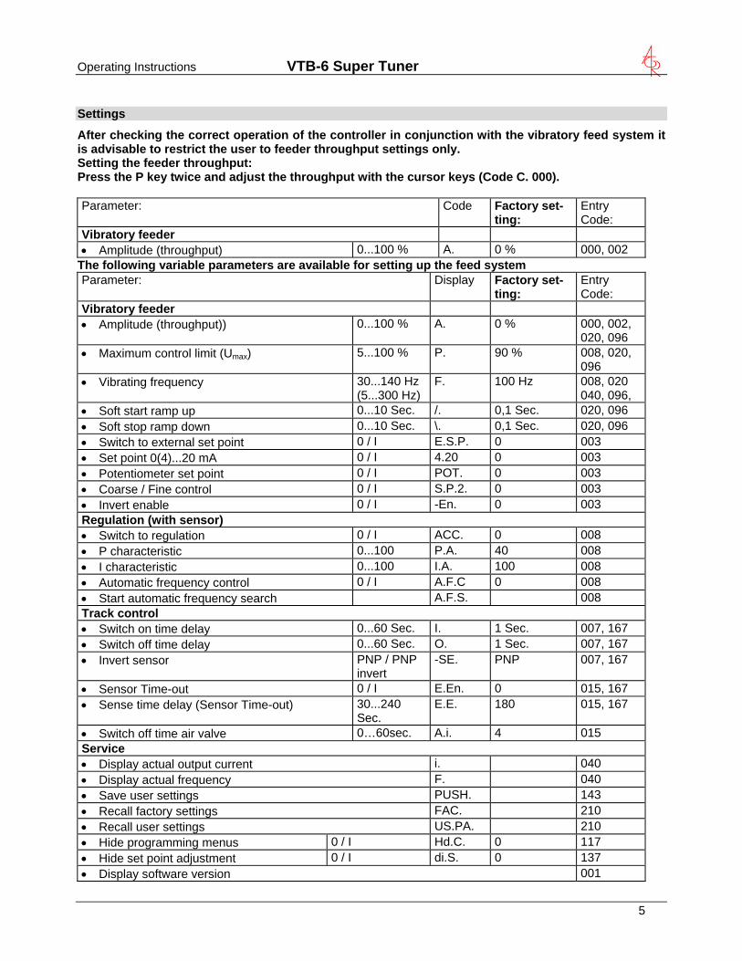
Settings
After checking the correct operation of the controller in conjunction with the vibratory feed system it is advisable to restrict the user to feeder throughput settings only. Setting the feeder throughput: Press the P key twice and adjust the throughput with the cursor keys (Code C. 000). Parameter: Code Entry
Code: Factory set-ting:
Vibratory feeder 0...100 % A. 0 % 000, 002 • Amplitude (throughput)
The following variable parameters are available for setting up the feed system Parameter: Display Entry
Code: Factory set-ting:
Vibratory feeder 0...100 % A. 0 % 000, 002,
020, 096 • Amplitude (throughput))
5...100 % P. 90 % 008, 020, 096
• Maximum control limit (Umax)
30...140 Hz(5...300 Hz)
F. 100 Hz 008, 020 • Vibrating frequency 040, 096,
0...10 Sec. /. 0,1 Sec. 020, 096 • Soft start ramp up 0...10 Sec. \. 0,1 Sec. 020, 096 • Soft stop ramp down 0 / I E.S.P. 0 003 • Switch to external set point 0 / I 4.20 0 003 • Set point 0(4)...20 mA 0 / I POT. 0 003 • Potentiometer set point 0 / I S.P.2. 0 003 • Coarse / Fine control 0 / I -En. 0 003 • Invert enable
Regulation (with sensor) 0 / I ACC. 0 008 • Switch to regulation 0...100 P.A. 40 008 • P characteristic 0...100 I.A. 100 008 • I characteristic 0 / I A.F.C 0 008 • Automatic frequency control A.F.S. 008 • Start automatic frequency search
Track control 0...60 Sec. I. 1 Sec. 007, 167 • Switch on time delay 0...60 Sec. O. 1 Sec. 007, 167 • Switch off time delay PNP / PNP invert
-SE. PNP 007, 167 • Invert sensor
0 / I E.En. 0 015, 167 • Sensor Time-out 30...240 Sec.
E.E. 180 015, 167 • Sense time delay (Sensor Time-out)
0…60sec. A.i. 4 015 • Switch off time air valve Service
i. 040 • Display actual output current F. 040 • Display actual frequency PUSH. 143 • Save user settings FAC. 210 • Recall factory settings US.PA. 210 • Recall user settings
0 / I Hd.C. 0 117 • Hide programming menus 0 / I di.S. 0 137 • Hide set point adjustment
001 • Display software version
5
Operating Instructions VTB-6 Super Tuner
6
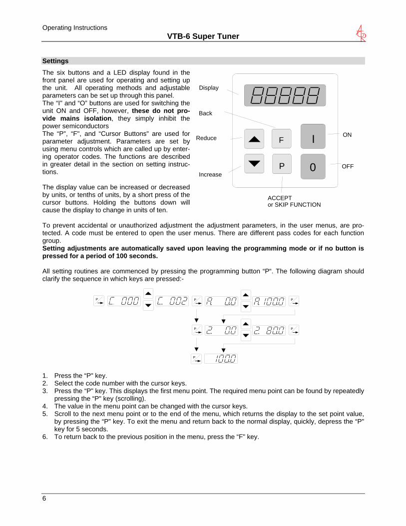
Settings
The six buttons and a LED display found in the front panel are used for operating and setting up the unit. All operating methods and adjustable parameters can be set up through this panel.
I
0P
FON
OFF
Display
ACCEPTor SKIP FUNCTION
Reduce
Increase
Back
The “I" and “O” buttons are used for switching the unit ON and OFF, however, these do not pro-vide mains isolation, they simply inhibit the power semiconductors The “P", “F", and “Cursor Buttons" are used for parameter adjustment. Parameters are set by using menu controls which are called up by enter-ing operator codes. The functions are described in greater detail in the section on setting instruc-tions. The display value can be increased or decreased by units, or tenths of units, by a short press of the cursor buttons. Holding the buttons down will cause the display to change in units of ten. To prevent accidental or unauthorized adjustment the adjustment parameters, in the user menus, are pro-tected. A code must be entered to open the user menus. There are different pass codes for each function group. Setting adjustments are automatically saved upon leaving the programming mode or if no button is pressed for a period of 100 seconds. All setting routines are commenced by pressing the programming button “P“. The following diagram should clarify the sequence in which keys are pressed:-
P P
P
P
P P
1. Press the “P" key. 2. Select the code number with the cursor keys. 3. Press the “P" key. This displays the first menu point. The required menu point can be found by repeatedly
pressing the “P" key (scrolling). 4. The value in the menu point can be changed with the cursor keys. 5. Scroll to the next menu point or to the end of the menu, which returns the display to the set point value,
by pressing the “P" key. To exit the menu and return back to the normal display, quickly, depress the “P" key for 5 seconds.
6. To return back to the previous position in the menu, press the “F" key.
Operating Instructions VTB-6 Super Tuner
Preliminary steps
• Check that the unit is correct for the local mains supply (rating plate information) and that it is correctly rated for the feed system.
• Connect the controller according to the connection diagram Important points
Using the control units described in this document, it is possible to adjust the feed system so that it runs at resonance. In this condition it is possible to obtain excessive output for a very low set point setting. Therefore extreme care should be taken to avoid causing damage to the drive coil, through hammering. !
In practice it is not possible to run at resonant frequency without accelerometer feedback because the system would be unstable and uncontrollable. The system must be set safely off resonance i.e. either above or below the natural frequency. Resonant frequency: Depending on the spring and mass design of the feeder system it is possible to have resonance at more than one frequency. These additional resonance points are multiples of the main fre-quency. For this reason in critical situations it is possible that the automatic frequency search will not find true resonance and in such cases the natural frequency must be determined manually. Operating frequency of the feeder coil It is possible that the current flowing through the coil will increase for a small frequency adjustment. This should be checked with a true RMS instrument for each new application as well as monitoring the coil for heat build-up. The coil should be designed for the correct operating frequency to prevent excessive current draw and the consequential overloading of the coil. Measurement of the output voltage and current The voltage and current cannot be measured with a regular instrument because the controller output uses an electronic inverter with a pulse width modulation signal. An effective measuring instrument such as a moving iron meter (analog) must be used. It is recommended that an analog instrument is used rather than an elec-tronic multi-meter which will give a misleading reading.
7
Operating Instructions VTB-6 Super Tuner
8
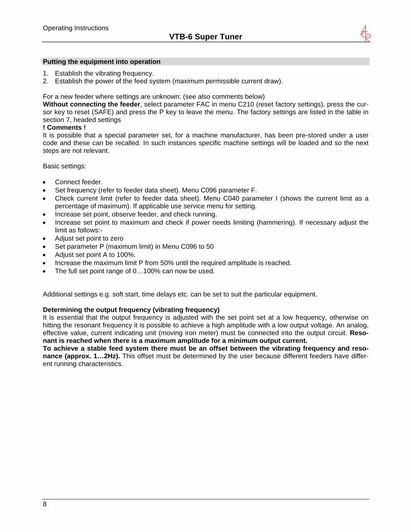
Putting the equipment into operation
1. Establish the vibrating frequency. 2. Establish the power of the feed system (maximum permissible current draw). For a new feeder where settings are unknown: (see also comments below) Without connecting the feeder, select parameter FAC in menu C210 (reset factory settings), press the cur-sor key to reset (SAFE) and press the P key to leave the menu. The factory settings are listed in the table in section 7, headed settings ! Comments ! It is possible that a special parameter set, for a machine manufacturer, has been pre-stored under a user code and these can be recalled. In such instances specific machine settings will be loaded and so the next steps are not relevant. Basic settings: • Connect feeder. • Set frequency (refer to feeder data sheet). Menu C096 parameter F. • Check current limit (refer to feeder data sheet). Menu C040 parameter I (shows the current limit as a
percentage of maximum). If applicable use service menu for setting. • Increase set point, observe feeder, and check running. • Increase set point to maximum and check if power needs limiting (hammering). If necessary adjust the
limit as follows:- • Adjust set point to zero • Set parameter P (maximum limit) in Menu C096 to 50 • Adjust set point A to 100%. • Increase the maximum limit P from 50% until the required amplitude is reached. • The full set point range of 0…100% can now be used. Additional settings e.g. soft start, time delays etc. can be set to suit the particular equipment. Determining the output frequency (vibrating frequency) It is essential that the output frequency is adjusted with the set point set at a low frequency, otherwise on hitting the resonant frequency it is possible to achieve a high amplitude with a low output voltage. An analog, effective value, current indicating unit (moving iron meter) must be connected into the output circuit. Reso-nant is reached when there is a maximum amplitude for a minimum output current. To achieve a stable feed system there must be an offset between the vibrating frequency and reso-nance (approx. 1…2Hz). This offset must be determined by the user because different feeders have differ-ent running characteristics.
Operating Instructions VTB-6 Super Tuner
Setting Instructions
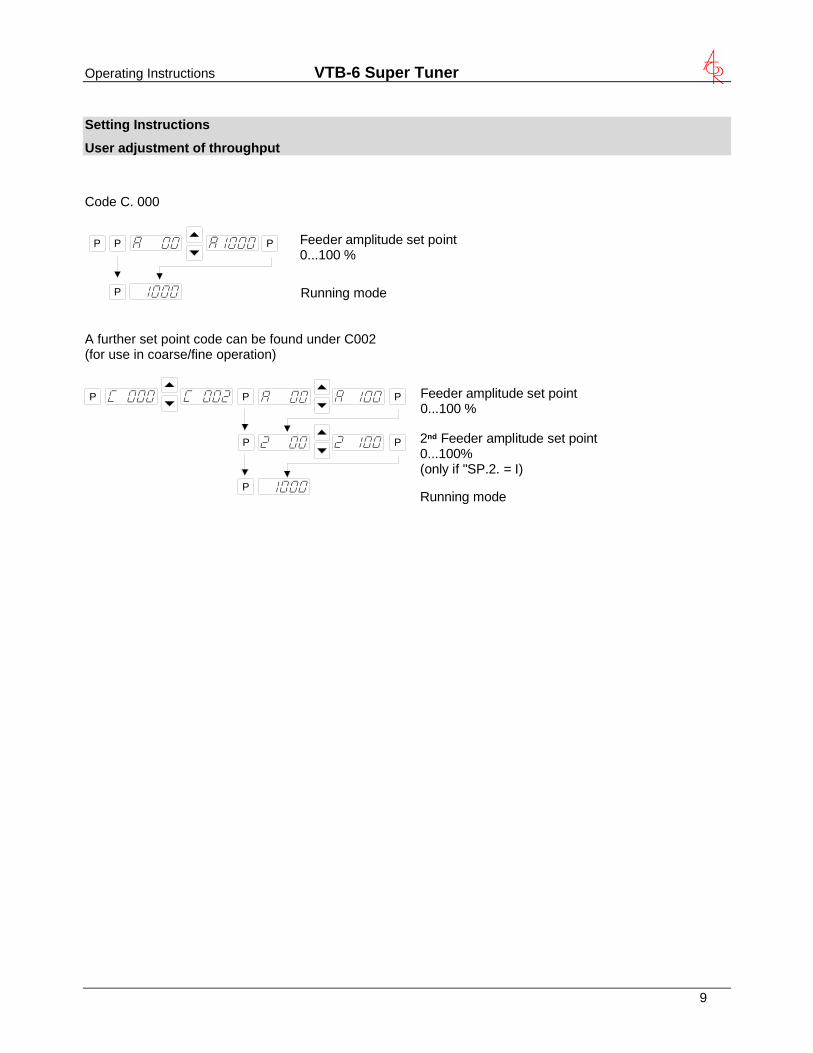
User adjustment of throughput
Code C. 000
Feeder amplitude set point0...100 %
Running mode
P P P
P
A further set point code can be found under C002 (for use in coarse/fine operation)
P P
P
P
P
P
Feeder amplitude set point0...100 %
2nd Feeder amplitude set point0...100%(only if "SP.2. = I)
Running mode
9
Operating Instructions VTB-6 Super Tuner
10
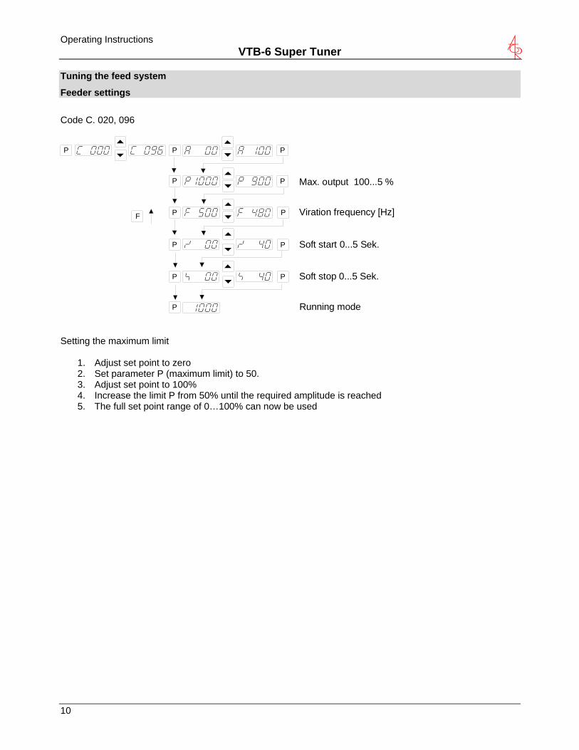
Tuning the feed system
Feeder settings
Code C. 020, 096
Soft start 0...5 Sek.
Soft stop 0...5 Sek.
Running mode
P P
P
P
P
P
P
P
P
P
P
P
F Viration frequency [Hz]
Max. output 100...5 %
Setting the maximum limit
1. Adjust set point to zero 2. Set parameter P (maximum limit) to 50. 3. Adjust set point to 100% 4. Increase the limit P from 50% until the required amplitude is reached 5. The full set point range of 0…100% can now be used
Operating Instructions VTB-6 Super Tuner
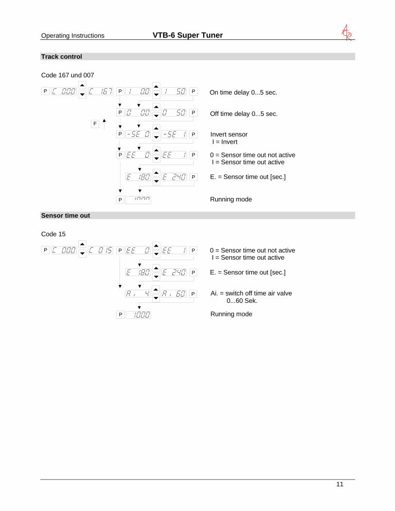
Track control
On time delay 0...5 sec.
Off time delay 0...5 sec.
Invert sensor I = Invert
Code 167 und 007
0 = Sensor time out not active I = Sensor time out active
E. = Sensor time out [sec.]
P P
P
P
P
P
P
P
P
P
F
Running modeP
Sensor time out
0 = Sensor time out not active I = Sensor time out active
E. = Sensor time out [sec.]
P P
P
Code 15
P
Running modeP
P Ai. = switch off time air valve 0...60 Sek.
11
Operating Instructions VTB-6 Super Tuner
12
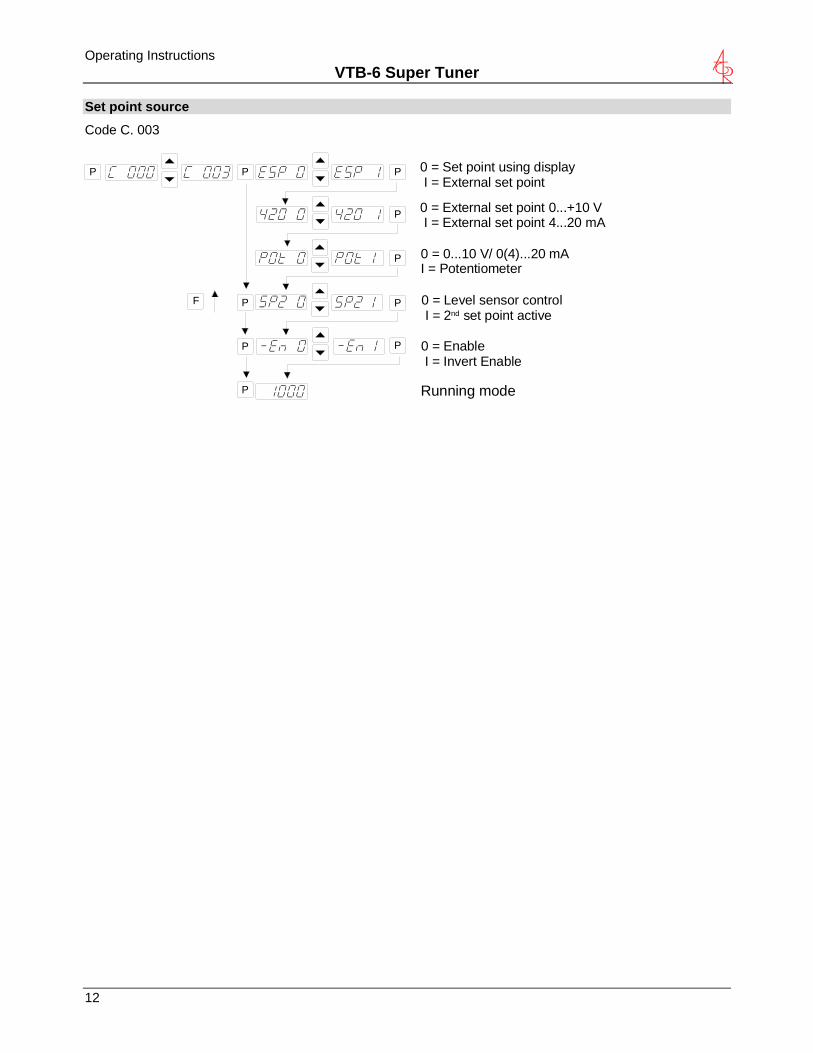
Set point source
Code C. 003
0 = Set point using display I = External set point
0 = External set point 0...+10 V I = External set point 4...20 mA
0 = Level sensor control I = 2nd set point active
0 = Enable I = Invert Enable
Running mode
P P P
P
P
P
P
P
P
F
0 = 0...10 V/ 0(4)...20 mAI = Potentiometer
P
Operating Instructions VTB-6 Super Tuner
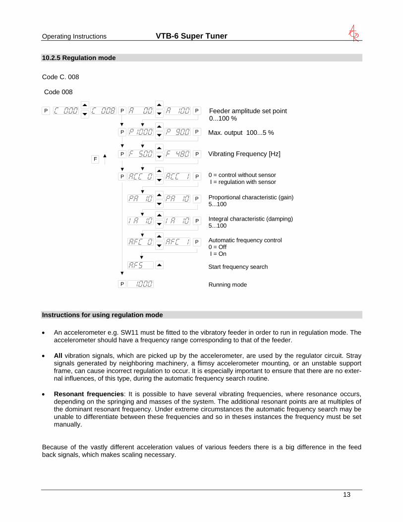
10.2.5 Regulation mode
Code C. 008 Code 008
Vibrating Frequency [Hz]
Max. output 100...5 %
P P
P
P
P
P
P
P
P
P
P
P
P
F
Feeder amplitude set point0...100 %
Proportional characteristic (gain)5...100
Start frequency search
Automatic frequency control0 = Off I = On
Integral characteristic (damping)5...100
0 = control without sensor I = regulation with sensor
Running mode Instructions for using regulation mode • An accelerometer e.g. SW11 must be fitted to the vibratory feeder in order to run in regulation mode. The
accelerometer should have a frequency range corresponding to that of the feeder. • All vibration signals, which are picked up by the accelerometer, are used by the regulator circuit. Stray
signals generated by neighboring machinery, a flimsy accelerometer mounting, or an unstable support frame, can cause incorrect regulation to occur. It is especially important to ensure that there are no exter-nal influences, of this type, during the automatic frequency search routine.
• Resonant frequencies: It is possible to have several vibrating frequencies, where resonance occurs,
depending on the springing and masses of the system. The additional resonant points are at multiples of the dominant resonant frequency. Under extreme circumstances the automatic frequency search may be unable to differentiate between these frequencies and so in theses instances the frequency must be set manually.
Because of the vastly different acceleration values of various feeders there is a big difference in the feed back signals, which makes scaling necessary.
13
Operating Instructions VTB-6 Super Tuner
14
Instructions for setting up the controller in regulation mode
Connect control unit Install sensor and connect to controller Determining the resonant frequency
Manual setting of the vibrating frequency It is essential that the output frequency is adjusted with the set point set at a low frequency, otherwise on hitting the resonant frequency it is possible to achieve a high amplitude with a low output voltage. An analog, effective value, current indicating unit (moving iron meter) must be connected into the output circuit. Reso-nant frequency is reached when there is a maximum amplitude for a minimum output current. Automatic frequency search • The feeder should be empty for a frequency search • Adjust the set point to zero • Select regulation mode (Menu C 008, Parameter ACC = I ) • The optimum frequency of the feeder is found, automatically, by initiating the frequency search (Menu C
008, Parameter A.F.S.). When this has been found the controller resets the set point back to its original value (0).
Optimization controller in regulation mode
Setting the control range 1. In Menu C. 096 set parameter P (Max Limit) to 50 % 2. Set A (Feeder throughput) to 100% 3. Increase limit P from 50% until the required maximum feeder throughput is achieved The full set point adjustment range of 0…100% can now be used Optimizing regulation: For unwanted feeder oscillation (hunting) or inadequate feedback regulation for load changes The response of the regulation circuit can be adjusted in menu C008 using the parameter PA (Proportional characteristic or circuit gain) and IA (Integral characteristic) In menu C008 reduce PA until the oscillations are reduced Parameter IA should be set to at 100 if possible
Operating Instructions VTB-6 Super Tuner
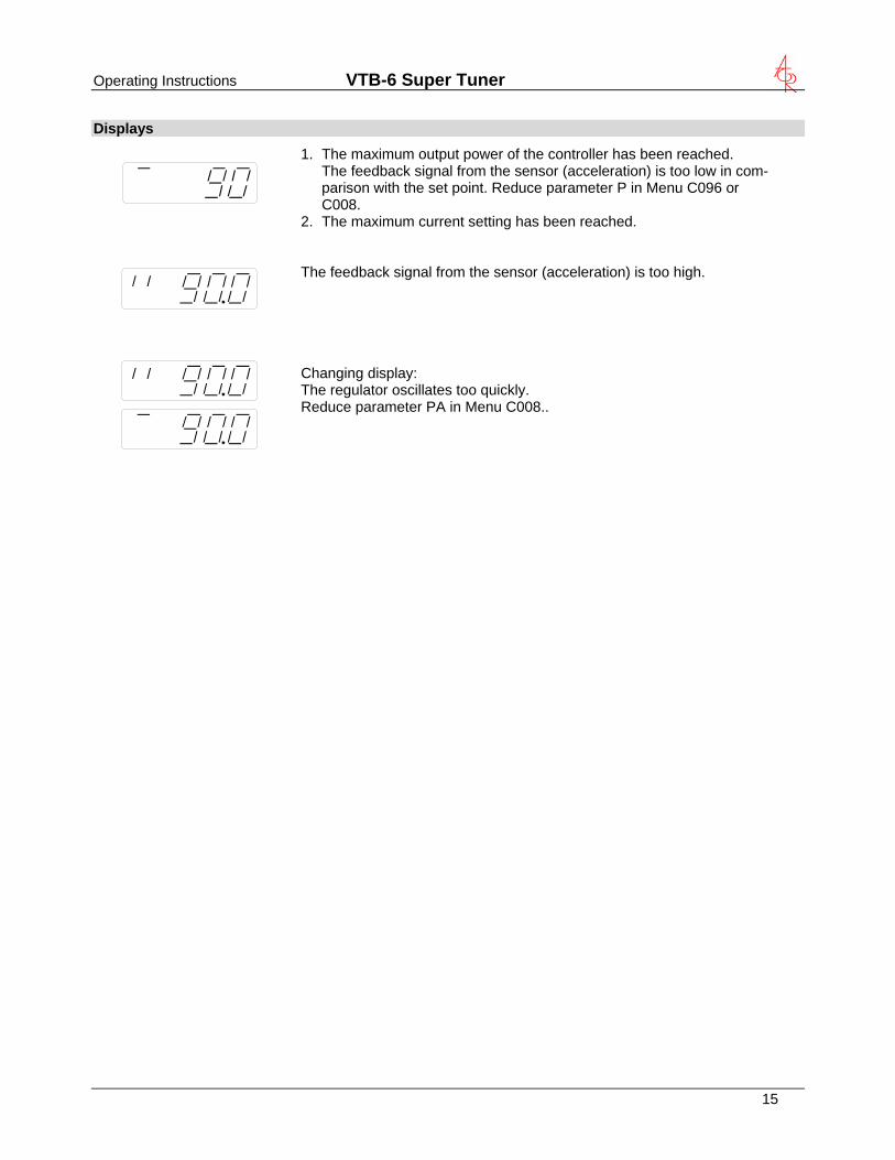
Displays
1. The maximum output power of the controller has been reached. The feedback signal from the sensor (acceleration) is too low in com-parison with the set point. Reduce parameter P in Menu C096 or C008.
2. The maximum current setting has been reached.
The feedback signal from the sensor (acceleration) is too high.
Changing display: The regulator oscillates too quickly. Reduce parameter PA in Menu C008..
15

Operating Instructions VTB-6 Super Tuner
16
Display actual current and frequency
Code C. 040
Running mode
P P
P
P Actual current (display only)
P P Actual frequency (display only)
Save selected parameters
Code C. 143
Save new parameters
Running mode
P P
P P
P Choose user parameter set
Recall user or factory settings
Code C. 210
Return to factorysettings
Return to usersettings
Running mode
P P
P
P
P
P
P P Choose user parameter set
Hide parameter menus
Code C. 117
I = Hide menus
Running mode
P P
P
P

Operating Instructions VTB-6 Super Tuner
Error messages / ERROR reset
Errors are indicated by an alternating code and ERROR display Overload limit Output level exceeded e.g. incorrect frequency setting, coil air-gap to wide. Short circuit trip Faulty coil, short circuit or defective cable.. Over voltage Supply voltage too high or back EMF from the coil at lower fre-quencies. Current spike limit Frequency set too low for installed coil or frequency altered too rapidly during setting up. Sensor fault (only when regulation mode is selected) Accelerometer not working or faulty. ERROR Reset through Menu C009 Sensor time out After sensor time out has elapsed ERROR Reset is achieved by pressing touch panel keys 0 or I during normal operation or by using Menu C009. In the event of an error check that this is not caused by incorrect wiring or cable faults. The error message, ERROR ACC, can also occur if regulation mode is chosen (in Menu C008) and an accelerometer is not con-nected, for example. Reset the error in the following manner:- ERROR RESET
P P
Clear Error
17
Operating Instructions VTB-6 Super Tuner
18
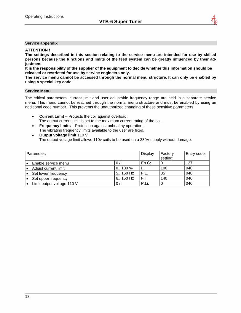
Service appendix
ATTENTION ! The settings described in this section relating to the service menu are intended for use by skilled persons because the functions and limits of the feed system can be greatly influenced by their ad-justment It is the responsibility of the supplier of the equipment to decide whether this information should be released or restricted for use by service engineers only. The service menu cannot be accessed through the normal menu structure. It can only be enabled by using a special key code. Service Menu
The critical parameters, current limit and user adjustable frequency range are held in a separate service menu. This menu cannot be reached through the normal menu structure and must be enabled by using an additional code number. This prevents the unauthorized changing of these sensitive parameters
• Current Limit – Protects the coil against overload. The output current limit is set to the maximum current rating of the coil.
• Frequency limits – Protection against unhealthy operation. The vibrating frequency limits available to the user are fixed.
• Output voltage limit 110 V The output voltage limit allows 110v coils to be used on a 230V supply without damage.
Parameter: Display Factory
setting: Entry code:
0 / I En.C: 0 127 • Enable service menu 0...100 % I. 100 040 • Adjust current limit 5...150 Hz F.L. 35 040 • Set lower frequency 6...150 Hz F.H. 140 040 • Set upper frequency 0 / I P.Li. 0 040 • Limit output voltage 110 V
Operating Instructions VTB-6 Super Tuner
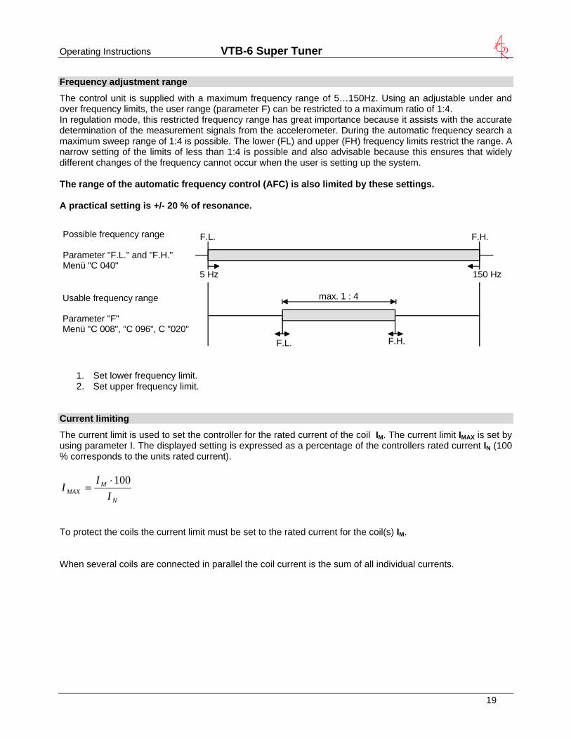
Frequency adjustment range
The control unit is supplied with a maximum frequency range of 5…150Hz. Using an adjustable under and over frequency limits, the user range (parameter F) can be restricted to a maximum ratio of 1:4. In regulation mode, this restricted frequency range has great importance because it assists with the accurate determination of the measurement signals from the accelerometer. During the automatic frequency search a maximum sweep range of 1:4 is possible. The lower (FL) and upper (FH) frequency limits restrict the range. A narrow setting of the limits of less than 1:4 is possible and also advisable because this ensures that widely different changes of the frequency cannot occur when the user is setting up the system. The range of the automatic frequency control (AFC) is also limited by these settings. A practical setting is +/- 20 % of resonance.
5 Hz 150 Hz
F.L. F.H.
F.L. F.H.
max. 1 : 4
Possible frequency range
Parameter "F.L." and "F.H."Menü "C 040"
Usable frequency range
Parameter "F"Menü "C 008", "C 096", C "020"
1. Set lower frequency limit. 2. Set upper frequency limit.
Current limiting
The current limit is used to set the controller for the rated current of the coil I . The current limit IM MAX is set by using parameter I. The displayed setting is expressed as a percentage of the controllers rated current IN (100 % corresponds to the units rated current).
N
MMAX I
II 100⋅=
To protect the coils the current limit must be set to the rated current for the coil(s) I . M When several coils are connected in parallel the coil current is the sum of all individual currents.
19
Operating Instructions VTB-6 Super Tuner
20
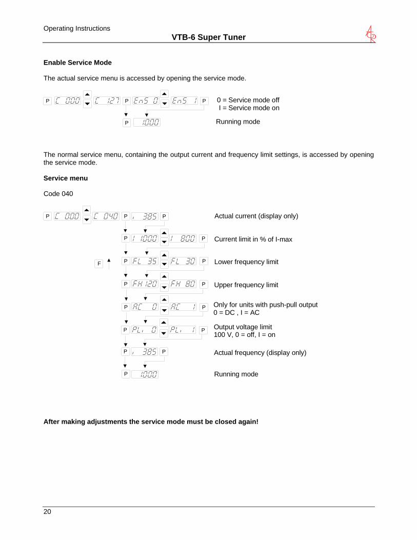
Enable Service Mode The actual service menu is accessed by opening the service mode.
0 = Service mode off I = Service mode on
P P
P
P
Running mode The normal service menu, containing the output current and frequency limit settings, is accessed by opening the service mode. Service menu Code 040
Upper frequency limit
Running mode
P P
P
P
P
P
P
P
P
P
Lower frequency limit
Current limit in % of I-max
Actual current (display only)
F
P P Actual frequency (display only)
Output voltage limit100 V, 0 = off, I = on
P P
P P Only for units with push-pull output0 = DC , I = AC
After making adjustments the service mode must be closed again!