control of pedestrian-induced vibrations of footbridges ... · control of pedestrian-induced...
TRANSCRIPT
CONTROL OF PEDESTRIAN-INDUCED VIBRATIONS OFFOOTBRIDGES USING TUNED LIQUID COLUMN DAMPERS
Michael REITERER1 & Franz ZIEGLER2
Institute of Rational Mechanics, Vienna University of Technology, Austria
Keywords: tuned liquid column damper, tuned mass damper, footbridges, pedestrian inducedvibrations
Abstract: In recently constructed footbridges unexpected lateral vibrations occurred due to alarge number of crossing pedestrians. To control and suppress these undesired vibrationssecondary passive damping devices, such as the conventional tuned mass damper (TMD),were installed to the bridge. In the present investigation it is proposed to apply a moreefficient and more economic type of damping device: the tuned liquid column damper(TLCD). A mechanical model of a coupled bridge/TLCD system is presented and analyzednumerically. The bridge is assumed to be a three degree-of-freedom (DOF) system.Furthermore, a small scale testing facility has been constructed in the laboratory of the TU-Institute. The experimental results are in good agreement with the theoretical predictions andindicate that TLCDs are effective damping devices for the control of pedestrian inducedvibrations of footbridges.
1 INTRODUCTIONTo mark the Millennium a new slender footbridge was built in London across the
river Thames. When the bridge was opened in June 2000, a large number of pedestrianscrossed the bridge, causing unexpected excessive lateral vibrations. Two days later thevibrations gave reason to close the bridge for the following 18 months. The extensive retrofitinvolved the use of fluid viscous dampers and conventional TMDs to increase the structuraldamping with a total cost of 10 million Euro, Dallard [1]. Similar problems emerged at theToda Park pedestrian cable-stayed bridge in Japan. When a sufficiently dense population ofpedestrians crossed the bridge, unexpected lateral vibrations occurred and made modificationsnecessary. To suppress the vibrations tuned liquid damper (TLD) were installed inside the boxgirder, as discussed in a paper by Fujino [2].
In the present investigation it is proposed to apply the more efficient and moreeconomic TLCD for suppressing pedestrian-induced vibrations of footbridges. The TLCDrelies on the motion of a liquid mass in a sealed tube to counteract the external motion, whilea built-in orifice plate induces turbulent damping forces that dissipate kinetic energy. Foroptimal tuning of TLCDs the natural frequency and equivalent linear damping coefficienthave to be chosen appropriately, likewise to the conventional TMDs, as given by Den Hartog[3]. The advantages of TLCDs over other types of damping devices are: simple tuning ofnatural frequency and damping, where the damping can be controlled by the opening angle ofthe built-in orifice plate, low cost of design and maintenance and a simple construction.Furthermore, the over-linear turbulent damping of the fluid motion increases the energydissipation rapidly in case of large vibration amplitudes of the liquid surface and contributesone more feature of superiority over conventional TMDs. 1 Dipl.-Ing. Michael REITERER, Research Assistant, Wiedner Hauptstr. 8 / E 201, A-1040 Vienna, Austria.Email: [email protected] Dr. Dr. h.c. Franz ZIEGLER, Professor, Head of Institute, Chairman of the Austrian Association of EarthquakeEngineering (OGE), Austria. Email: [email protected]

In order to study the damping effectiveness of optimally tuned TLCDs a detailedtheoretical and experimental investigation is carried out. Thereby, the nonlinear turbulentdamping of the fluid motion and a general plane motion of the TLCD is considered. Thebridge is assumed to be a three DOF system, where the interaction force and moment from theTLCD dynamics are assigned. It will be shown that optimally tuning of the TLCD to thefundamental frequency of the bridge, whose corresponding mode has a dominant horizontalresponse, similar to Londons Millenium Bridge, reduces the resonant peak of the first modeby 65%. Hence, the proposed TLCD turns out to be an effective damping device for theundesired pedestrian induced footbridge vibration.
2 MECHANICAL MODELBasically, the response of footbridges due to pedestrian excitation is a combination
of horizontal, vertical and rotational motions. The equations of motion for the complex hybridbridge/TLCD system are derived by a substructure synthesis method, which splits theproblem into two parts.
2.1 Substructure Separated TLCDIn a first step the TLCD is separated from the bridge and considered under combined
and assigned horizontal wt , vertical vt and rotational ϕ t excitations, as illustrated in Fig. 1.
Fig. 1 Separated TLCD under combined horizontal, vertical and rotational excitations
The TLCD parameters are the horizontal length of the liquid column B, the length of theliquid column in the inclined pipe section at rest H , i.e. the total length is B H+ 2 , theinclined and horizontal cross-sectional areas AH and AB, respectively, and the opening angleof the inclined pipe section π β π/ /6 2< < . The relative and incompressible flow of theliquid inside the pipe is described by the liquid surface displacement u . Furthermore, thereference point A is chosen symmetrically, whereby the absolute acceleration
vaA is separated
into the moving reference system,
va
a
a
w v
w vAA x
A z
t t t t
t t t t
˙ cos ˙ sin
˙ sin ˙ cos .,
,
=
=
−
+
ϕ ϕ
ϕ ϕ(1)
In Fig. 1 a closed piping system is assumed, thus the air inside the pipe is compressed orreleased, depending on the liquid surface displacement. Hence, a non negligible pressure

difference ∆p p p= −2 1 can built up on either side of the inclined pipe sections, whoseinfluence on the undamped circular natural frequency of the TLCD is defined in Eq. (4).Applying the modified Bernoulli equation along the relative non-stationary streamline in themoving frame and in an instant configuration, Ziegler [4, p. 497], yields the nonlinearparametric excited equation of motion of the TLCD,
˙ ˙ ˙ cos sin ˙ ,,,u u u
a
gu a g
BL A t
A z
AA x t+ + + −
= − −( ) +δ ω ϕ κ
ωκ ϕ κ2
2
2
2 1 2Ω
Ω (2)
where the geometry coefficients κ κ κ, , 1 2 and the effective length Leff of the liquid column
are defined by
κβ
κβ
κβ
=+
= =+
= +B H
L
H
L
B H
LL H
A
AB
eff eff effeff
H
B
2 2 221 2
cos,
sin,
cos, . (3)
The undamped circular natural frequency of the TLCD includes the air spring effect due tosealed tubes and is given by
ω βρ
Aeff eff
g
L
n p g
h= +
sin
/ ,
2 0 (4)
where n denotes the polytropic index, which is determined by the type of state change of thegas. For an adiabatic process of any two atomic gas n =1 4. whereas for a isothermal (slow)process n =1 0. . Any other process is in between those two extreme situations. Furthermore,p g0 , , ρ and heff denote the initial atmospheric pressure p Pa0
510= , the liquid density, e.g.
water ρ =1000 3kg m/ , the gravity constant and the effective height of the air spring, animportant design variable as it will directly influence the TLCD undamped circular frequency.In Eq. (2) the head loss coefficient δL due to turbulent losses along the relative streamline canbe controlled by the opening angle of the built-in orifice plate. The head loss coefficients ofstationary flowing fluids in relevant pipe elements are given e.g. in Idelchick [5].
The time variant stiffness parameter in Eq. (2) leads to parametric excitedoscillations and is caused by rotation and vertical excitation of the TLCD. Consequently,under special conditions of the lightly damped TLCD, the instability phenomenon ofparametric resonance occurs. Parametric resonance increases the TLCD vibration amplitudein an undesired manner and thus, the damping effectiveness of the optimally tuned TLCDmight get worse. However, in a recent paper by Reiterer and Ziegler [6] it is indicated thatdamping of the fluid motion strongly influences the occurrence of parametric resonance.Sufficiently high damping prevents parametric resonance. In the present investigation optimaltuning of the TLCD (tuned by frequency and equivalent linear damping) leads to asufficiently high fluid damping for the range of vertical excitation amplitudes considered andhence, no undesired worsening-effects are observed. It has to be mentioned that parametricresonance may also exist for the conventional pendulum type TMD, whose point ofsuspension moves vertically. In addition, the over-linear turbulent damping stabilizes theunstable motion and thus, limits the vibration amplitude of the TLCD. For the optimal designof the TLCD, which is shown in Section 4, the nonlinear turbulent damping term δL has to be
transformed to its equivalent linear expression ζA . Basically, the method of harmonic balance[4, p. 619] is used. Applying this method yields the equivalent linear viscous damping term
ζδπA
LU ,=
43
0 (5)
where U0 denotes the relative vibration amplitude of the liquid surface. Thereby, the value ofU0 is determined from numerical simulations of the linear system and commonly chosen asU U0 = max . Subsequently, optimal tuning of the TLCD adjusts only the circular naturalfrequency ωA and the equivalent linear viscous damping coefficient ζA .
In a second step, the interaction force and the interaction moment caused by theTLCD dynamics have to be determined. Conservation of moment renders the nonlinearinteraction force
vF in x' and z' direction of the moving reference system (acting on the fluid
body),
˙ ˙ ˙
˙ ˙ ˙ ˙
,v vF m a m
u uH
uu H u
u uH
u H u uu
f A f= +
−( ) + + +( )( )
− +( ) + − +( ) +( )
κ κ
κ κ
Ω Ω Ω
Ω Ω Ω
21
2 2
12 2 2 2
12
4
21
22 2
(6)
where Ω = ϕ t and ˙ ˙Ω =ϕ t denotes the angular velocity and angular acceleration. The geometrydependent coefficients of Eq. (6) are given by
κβ
κβ
=+
= = +B H
L
H
LL H
A
ABB
H
2 22
11
11
cos,
sin , . (7)
In Eq. (6) m A Lf H= ρ 1 defines the total fluid mass, and L1 is a length dependent from the
cross section, which becomes equal to Leff in case of A AH B= . Conservation of angular
momentum with respect to the accelerated reference point A , see Fig. 1, yields the nonlinearresultant interaction moments MAy (acting on the fluid body),
M m u a gH
H u a g
Bu u uu H
Ay f A z t A x t= − +( )+ +( ) −( )
−
− + +( )+
cos sin
˙ ˙ ˙ ˙ ,
, ,κ ϕ κ ϕ
κ κ κ
12 2
1 22
32
12
22Ω Ω Ω (8)
where the geometry coefficient κ3 due to rotation is given by
κ β31
2
2
3
3
23
13
4
32 8
= + + +
cos .
H
L
B
H
B
H
A
A
B
HB
H
(9)
Several nonlinearities show up in Eq. (6) and (8), which are considered in the overallnumerical simulation. Furthermore, the interaction moment MAy includes the additional

undesired moment from gravity, acting on the displaced center of fluid mass CF , see Fig. 1,which is always neglected in the theory of conventional TLCDs and TMDs.
2.2 Substructure Separated Bridge with Assigned Interaction Force and MomentIn this Section the equations of motion of the separated bridge with assigned
interaction force and moment from the TLCD dynamics are derived. Thereby, the bridge isassumed to be a three DOF system with its deformation, given by the horizontal displacementv , vertical displacement w and rotation ϑ , as indicated in Fig. 2.
Fig. 2 Separated three DOF bridge with assigned interaction forces and moment from theTLCD dynamics: F F My z Ax, , ; time periodic excitation forces: Fv , Fw ; center of stiffness
CS ; center of mass CM ; horizontal kv , vertical kw and torsional kϑ stiffness
The bridge is excited through the combined horizontal and vertical time periodic excitationforces Fv and Fw , respectively, which are acting in the center of stiffness CS . In the selectedmechanical model of the bridge, the reference point CS does not coincide with the center ofmass CM and thus, coupled bending and torsional motions are expected. Thereby, thecomponents of the distance between CM and CS are denoted by c and d , as shown in Fig. 2.Applying conservation of momentum and moment of momentum with respect to CS yieldsthe following nonlinear coupled equations of motion, where a small angle of rotation ϑ isassumed. In Eq. (10) the mass of the TLCD (without fluid) m m mT f= − is included in the
bridge mass M .

˙ ˙ ˙ ,
˙ ˙ ˙ ,
˙ ˙ ˙ ˙ ,
v d v vF
M
F
M
F
M
w c w wF
M
F
M
F
M
M
Icw
M
Idv
M
I
F
Iz I I
v v vv y z
w w ww y z
Ax yA C
− + + = + −
+ + + = + +
+ − + + = − =
ϑ ζ ϑ
ϑ ζ ϑ
ϑ ζ ϑ ϑϑ ϑ ϑ
2
2
2
2
2
2
Ω Ω
Ω Ω
Ω ΩMM
c M d M+ +2 2 .
(10)
ζ ζ ζϑv w, , are the linear viscous damping coefficients of the bridge, and Ω Ω Ωv w, , ϑ arethe corresponding uncoupled and undamped circular natural frequencies,
Ω Ω Ωvv
w
k
M
k
M
k
I= = = , , .ϑ
ϑϑ (11)
Furthermore, I denotes the mass moment of inertia with respect to CS , and zA is the verticaldistance between A and CS . The nonlinear interaction forces and moment, given in Eq. (6)and (8), are transformed with respect to the new reference point CS to main coordinates of thebridge,
F m a z u uH
uu H u
F m a z u uH
u H u
y f A y A
z f A z A
˙ ˙ ˙ ˙ ˙ ˙ ,
˙ ˙ ˙ ˙ ˙
,
,
= − +
+ −( )− + +( )( )
= − +
+ +( )+ − +( )
ϑ κ ϑ κ ϑ ϑ
ϑ κ ϑ ϑ κ
21
2 2
21
2 2 2
12
4
21
22 ˙ ˙ ,ϑ 2 2+( )
uu
M m u a z gH
H u a z g
Bu u uu H
Ax f A z A A y A ˙ ˙
˙ ˙ ˙ ˙ ˙ .
, ,= − − + + + + − + + −
− − + −
( )
( )( )
( )
κ ϑ κ ϑ ϑ
κ κ ϑ ϑ κ ϑ
21
2 2
1 22
32
12
22
(14)
where the acceleration aA of the previous reference point A in main coordinates and in caseof small angles of rotation ϑ is given by,
aa
a
v w
v wAA y
A z
˙ ˙
˙ ˙ .,
,
=
=
+
− +
ϑ
ϑ(15)
Finally, the equation of motion of the separated TLCD is transformed to the main coordinatesof the bridge,
˙ ˙ ˙˙ ˙ ˙
˙ ˙ ˙ ˙ ˙ .u u u
w
g
v
g
z
gu v w z g
BL A
A
AA+ + − + + −
= − − − + +[ ] −δ ω ϑ ϑ κ
ϑω
κ ϑ ϑ ϑ κ ϑ2 22
2
2 112
(17)
Substituting the transformed interaction forces and moment, Eq. (14) in Eq. (10), yieldstogether with Eq. (17) a set of four equations of motion for the unknown displacements v w, ,
the rotation ϑ , and the displacement of the liquid surface u . The performed numericalsimulations of the coupled bridge/ TLCD system are presented in the Section 4.
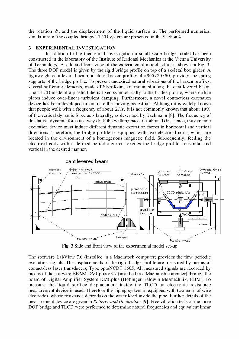
3 EXPERIMENTAL INVESTIGATIONIn addition to the theoretical investigation a small scale bridge model has been
constructed in the laboratory of the Institute of Rational Mechanics at the Vienna Universityof Technology. A side and front view of the experimental model set-up is shown in Fig. 3.The three DOF model is given by the rigid bridge profile on top of a skeletal box girder. Alightweight cantilevered beam, made of brazen profiles 4 900 20 50× / / , provides the springsupports of the bridge profile. To prevent undesired natural vibrations of the brazen profiles,several stiffening elements, made of Styrofoam, are mounted along the cantilevered beam.The TLCD made of a plastic tube is fixed symmetrically to the bridge profile, where orificeplates induce over-linear turbulent damping. Furthermore, a novel contactless excitationdevice has been developed to simulate the moving pedestrian. Although it is widely knownthat people walk with a frequency of about 2Hz , it is not commonly known that about 10%of the vertical dynamic force acts laterally, as described by Bachmann [8]. The frequency ofthis lateral dynamic force is always half the walking pace, i.e. about 1Hz . Hence, the dynamicexcitation device must induce different dynamic excitation forces in horizontal and verticaldirections. Therefore, the bridge profile is equipped with two electrical coils, which arelocated in the environment of a homogenous magnetic field. Subsequently, feeding theelectrical coils with a defined periodic current excites the bridge profile horizontal andvertical in the desired manner.
Fig. 3 Side and front view of the experimental model set-up
The software LabView 7.0 (installed in a Macintosh computer) provides the time periodicexcitation signals. The displacements of the rigid bridge profile are measured by means ofcontact-less laser transducers, Type optoNCDT 1605. All measured signals are recorded bymeans of the software BEAM-DMCplusV3.7 (installed in a Macintosh computer) through theboard of Digital Amplifier System DMCplus (Hottinger Baldwin Messtechnik, HBM). Tomeasure the liquid surface displacement inside the TLCD an electronic resistancemeasurement device is used. Therefore the piping system is equipped with two pairs of wireelectrodes, whose resistance depends on the water level inside the pipe. Further details of themeasurement device are given in Reiterer and Hochrainer [9]. Free vibration tests of the threeDOF bridge and TLCD were performed to determine natural frequencies and equivalent linear
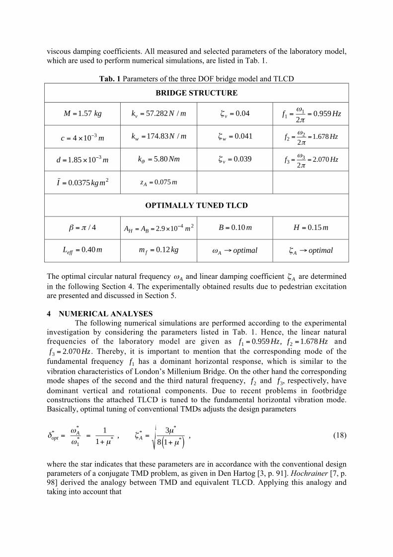
viscous damping coefficients. All measured and selected parameters of the laboratory model,which are used to perform numerical simulations, are listed in Tab. 1.
Tab. 1 Parameters of the three DOF bridge model and TLCD
BRIDGE STRUCTURE
M kg=1 57. k N mv = 57 282. / ζ v = 0 04. f Hz11
20 959= =
ωπ
.
c m= × −4 10 3 k N mw =174 83. / ζw = 0 041. f Hz22
21 678= =
ωπ
.
d m= × −1 85 10 3. k Nmϑ = 5 80. ζ v = 0 039. f Hz33
22 070= =
ωπ
.
I kgm= 0 0375 2. z mA = 0 075.
OPTIMALLY TUNED TLCD
β π= / 4 A A mH B= = × −2 9 10 4 2. B m= 0 10. H m= 0 15.
L meff = 0 40. m kgf = 0 12. ωA optimal→ ζA optimal→
The optimal circular natural frequency ωA and linear damping coefficient ζA are determinedin the following Section 4. The experimentally obtained results due to pedestrian excitationare presented and discussed in Section 5.
4 NUMERICAL ANALYSESThe following numerical simulations are performed according to the experimental
investigation by considering the parameters listed in Tab. 1. Hence, the linear naturalfrequencies of the laboratory model are given as f Hz f Hz1 20 959 1 678= =. , . andf Hz3 2 070= . . Thereby, it is important to mention that the corresponding mode of the
fundamental frequency f1 has a dominant horizontal response, which is similar to thevibration characteristics of Londons Millenium Bridge. On the other hand the correspondingmode shapes of the second and the third natural frequency, f2 and f3, respectively, havedominant vertical and rotational components. Due to recent problems in footbridgeconstructions the attached TLCD is tuned to the fundamental horizontal vibration mode.Basically, optimal tuning of conventional TMDs adjusts the design parameters
δωω µ
ζµ
µopt
AA
**
* **
*
* , ,= =
+=
+( )1
1
1
3
8 1(18)
where the star indicates that these parameters are in accordance with the conventional designparameters of a conjugate TMD problem, as given in Den Hartog [3, p. 91]. Hochrainer [7, p.98] derived the analogy between TMD and equivalent TLCD. Applying this analogy andtaking into account that
µκ µ
µ κµ*
, ,=
+ −( )=
2
21 1
m
Mf (19)
relates the optimal design parameters of the TMD to the corresponding values in thelinearized equation of motion of the TLCD. Substituting Eq. (5) in Eq. (2) gives,
δδ
µ κζ ζopt
optA opt A opt=
+ −( )= = =
*
, ,*
. , . .
1 10 943 0 127
2(20)
Thereby, the ratio of fluid mass mf to total bridge mass M is obtained from Tab. 1:
µ = 0 076. (i.e. about 8 %), and κ is defined in Eq. (3). The value of µ is higher than therecommended mass ratio µ = −0 5 3. % for real bridge structures. By means of the valueδopt = 0 943. , given in Eq. (20), the optimal natural frequency of the TLCD is determined,
f HzAA
opt . .= = =ωπ
δωπ2 2
0 9041 (21)
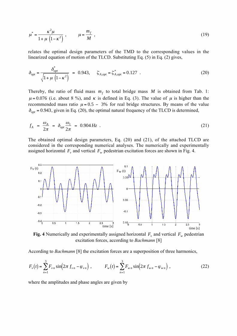
The obtained optimal design parameters, Eq. (20) and (21), of the attached TLCD areconsidered in the corresponding numerical analyses. The numerically and experimentallyassigned horizontal Fv and vertical Fw pedestrian excitation forces are shown in Fig. 4.
time [s]
Fv (t)
time [s]
Fw (t)
Fig. 4 Numerically and experimentally assigned horizontal Fv and vertical Fw pedestrianexcitation forces, according to Bachmann [8]
According to Bachmann [8] the excitation forces are a superposition of three harmonics,
F t F f F t F fv v n v n v nn
w w n w n w nn
( ) = −( ) ( ) = −( )= =
∑ ∑sin , sin ,2 21
3
1
3
π ϕ π ϕ (22)
where the amplitudes and phase angles are given by

F N F N F N
F N F N F N
v v v v v v
w v v w w w
1 2 3 1 2 3
1 2 3 1 2 3
0 14 0 034 0 15 5 3 5 0
0 10 0 023 0 024 0 2 2
= = = = = =
= = = = = =
. , . , . , / , / , ,
. , . , . , , / , / .
ϕ π ϕ π ϕ
ϕ ϕ π ϕ π
(23)
All numerical simulations are performed by the software Matlab 6.5. It is emphasized that thenonlinear turbulent damping term δL u u˙ ˙ in Eq. (2) is replaced by its equivalent linear one:2ζ ωA A u, which is obtained from the previous optimization process, Eq. (20). Thisapproximation is only valid when the criterion for preventing parametric resonance isfullfilled, given in Reiterer and Ziegler [7]. For this study the required equivalent linear fluiddamping to prevent parametric resonance at the critical vertical excitation frequency f fw A= 2is given by,
ζ ωA requ Av
g, . ,= =0 2 0 033 (24)
where v m0 0 01= . is selected according to the experimental result and ωA is given in Eq. (21).The required value ζA requ, .= 0 033 turns out to be much lower than the optimal one
ζA = 0 127. , given in Eq. (20), and thus, no undesired worsening effects on the optimaldamping characteristics of the attached TLCD are expected. The results obtained bynumerical simulation are presented and discussed in the following Section.
5 COMPARISON OF EXPERIMENTAL AND NUMERICAL RESULTSThe experimentally and numerically obtained steady state horizontal displacement v
of the bridge reference point CS with and without TLCD is shown in Fig. 5. Thereby, theexcitation frequencies of the combined horizontal and vertical periodic excitation forces Fv
and Fw , respectively, are assumed to be: f Hz f f f fv v v v v1 2 1 3 10 95 2 3= = =. , , andf Hz f f f fw w w w w1 2 1 3 11 90 2 3= = =. , , , i.e. the excitation frequency fv1 is close to the
fundamental natural frequency f1.
Experiment
v [mm]
0 10 30 4020
Numerical Simulation
20 30 40 50 60
time [s]
10
20
30
40
0
-10
-20
-30
-40
without TLCDwith TLCD
v [mm]
time [s]
Fig. 5 Experimentally and numerically obtained results of steady state horizontaldisplacement v of the bridge reference point CS with and without TLCD; combined
horizontal Fv and vertical Fw excitation forces
The light line represents the steady state vibration without TLCD and the heavy line showsthe reduced response due to the optimal tuned TLCD. The experimental and numerical resultsare in good agreement. Another important response parameter, the dynamic magnificationfactor (DMF) is shown in Fig. 6 for both experiment and numerical simulation. By inspection,

an excellent agreement is observed, and it can be seen that the installation of the optimaltuned TLCD reduces the resonant peak of the first mode of the bridge by 65% .
Experiment
0,7 0,9 1,1 1,25
1,4 1,8 2,2 2,52,1 2,7 3,3 3,75
1,4 1,8 2,2 2,502,8 3,6 4,4 5,0
4,2 5,4 6,6 7,75
excitation frequencies fv, fw [Hz]
fw1:fw2:fw3:
fv1:fv2:fv3:
DMF
without TLCDwith TLCD
Numerical Simulation
without TLCDwith TLCD
excitation frequencies fv, fw [Hz]
0,7 0,8 0,9 1,0 1,1 1,21,4 1,6 1,8 2,0 2,2 2,42,1 2,4 2,7 3,0 3,3 3,6
4,2 4,8 5,4 6,0 6,6 7,2
fw1:fw2:fw3:
fv1:fv2:fv3:
2,8 3,2 3,6 4,0 4,4 4,81,4 1,6 1,8 2,0 2,2 2,4
2,00
0,00
4,00
6,00
8,00
10,00
12,00
14,00DMF
65 % 65 %
Fig. 6 Experimental and numerical obtained result of the DMF; horizontal displacement v ;combined horizontal Fv and vertical Fw excitation forces
For the sake of completeness Fig. 7 shows the experimentally and numerically derived DMFof the bridge vertical displacement w .
Experiment
1,4 1,8 2,2 2,52,8 3,6 4,4 5,0
4,2 5,4 6,6 7,5
0,7 0,9 1,1 1,25
1,4 1,8 2,2 2,5
2,1 2,7 3,3 3,75
fw1:fw2:fw3:
excitation frequencies fv, fw [Hz]
fv1:fv2:fv3:
DMF
without TLCDwith TLCD
Numerical Simulation
1,4 1,6 1,8 2,0 2,2 2,42,8 3,2 3,6 4,0 4,4 4,84,2 4,8 5,4 6,0 6,6 7,2
excitation frequencies fv, fw [Hz]
0,7 0,8 0,9 1,0 1,1 1,2
2,1 2,4 2,7 3,0 3,3 3,6
fw1:fw2:fw3:
fv1:fv2:fv3:
1,4 1,6 1,8 2,0 2,2 2,4
DMF
without TLCDwith TLCD
Fig. 7 Experimental and numerical obtained result of the DMF; vertical displacement w;combined horizontal Fv and vertical Fw excitation force
Thereby, the combined horizontal and vertical time periodic excitation forces are sweepedwithin the frequency range of interest. Again, the experiment and numerical simulations are ingood agreement. Fig. 7 indicates that the attached TLCD has no or only a little influence onthe vertical displacement w within the range of vertical excitation amplitudes considered.

6 CONCLUSIONThe aim of this investigation was to study the reduction of undesired pedestrian
induced footbridge vibrations by an innovative passive damping device. It is proposed toinstall the more efficient and more economic tuned liquid column damper (TLCD) at discretesections along the bridge. A detailed theoretical and experimental investigation has beencarried out, considering nonlinear turbulent damping and a general plane motion of theTLCD. The equation of motion of the TLCD turns out to be time variant and hence, sensitiveto parametric resonance. The instability phenomenon of parametric resonance increases theliquid surface displacement in an undesired manner and hence, the performance of theattached TLCD might get worse. However, previous investigations indicate that optimaldamping of the fluid motion, which is higher than the natural one, is crucial in order toprevent parametric resonance. For this study the optimal damping coefficient turns out to beζA = 0 127. which is much higher than the required one ζA requ, .= 0 033 and thus, no undesired
worsening effects are observed. The bridge is assumed to be a three DOF system, whereby thenonlinear interaction forces and interaction moment from the TLCD dynamics are assigned.The TLCD is tuned to the fundamental frequency of the bridge, whose corresponding modehas a dominant horizontal response characteristic, similar to Londons Millenium Bridge. Thenumerically and experimentally obtained results are in good agreement and indicate the largedamping effect of the optimally tuned TLCD. It is shown that the attached TLCD reduces theresonant peak of the first mode by 65% . In conclusion the proposed TLCD turns out to be aneffective damping device for undesired pedestrian footbridge vibrations.
References[1] DALLARD ET. AL., The London Millenium Footbridge, The Structural Engineer, Vol. 79 / No. 22, (p. 17-33), 2001[2] NAKAMURA S. & FUJINO Y., Lateral Vibration on a Pedestrian Cable-Stayed Bridge, Structural Engineering International, (p. 295-300), Vol. 4, 2002[3] DEN HARTOG J. P., Mechanical Vibrations, Reprint of the 4th ed., McGrawHill, 1956[4] ZIEGLER F., Mechanics of Solids and Fluids, 2nd ed., Vienna New York, Springer, 1998[5] IDELCHICK, I. E., Handbook of Hydraulic Resistance, Coefficient of Local Resistance and Friction, Available from the U.S. Department of Commerce, Springfield, 1960[6] REITERER M. & ZIEGLER F., Combined Seismic Activation Of A SDOF-Building With A Passive TLCD Attached, in: Proc. 13th World Conference on Earthquake Engineering, Vancouver, B.C., Canada, Paper No. 226, (15 pages), 2004[7] HOCHRAINER M. J., Control of vibrations in civil engineering structures with special emphasis on tall buildings, Dissertation, Institut für Allgemeine Mechanik (E201), TU- Wien, A-1040 Wien, 2001[8] BACHMANN H. & AMMANN W., Vibrations in Structures Induced by Man and Machines, Structural Engineering Documents, International Association for Bridge and Structural Engineering (IABSE), 1987[9] REITERER M. & HOCHRAINER M.J., Parametric Resonance In Tuned Liquid Column Dampers: An Experimental Investigation, IAZ, 2004, in print.