control procedures for source document microfilm processing · 1 micrographic quality d-17 control...
TRANSCRIPT

1
Micrographic Quality D-17
Control Procedures for Source
Document Microfilm
Processing
With Image Optimization
Procedures for Diazo,
Vesicular and Silver
Microfilm Duplication
2
Table of contents
Introduction ....................................................................................................................................... 1
What is process control? ............................................................................................................... 1
Why use process control? ............................................................................................................. 1
Source document process control ...................................................................................................... 2
Elements of process control ........................................................................................................... 2
Control strips .................................................................................................................................. 2
Imagelink Pre-exposed control strips ............................................................................................ 2
Figure 1: Control strips examples ................................................................................................... 2
Sensitometer exposed control strips ............................................................................................. 2
Process control emulsion ...................................................................................................... 2
Densitometer ........................................................................................................................ 3
Process control charts .................................................................................................................... 3
Hydrometer ........................................................................................................................... 3
Source document process control procedures ................................................................................. 3
Establishing aims ............................................................................................................................. 3
Table 1: Process control setup for Imagelink Pre-exposed control strips .................................... 4
Figure 2: Daily process control aim examples .............................................................................. 5
Process control setup for crossing over control aim to a sensitometer control strip ................ 5
Daily checks ....................................................................................................................................... 6
Processing control limits ....................................................................................................... 6
Control limit ......................................................................................................................... 6
Specification limits .............................................................................................................. 6
Daily checks ................................................................................................................................... 6
Evaluating results ........................................................................................................................... 6
Resolution / contrast checks ......................................................................................................... 6
Diagnose and correct an out-of-control process .................................................................................... 7
Table 2: For general processing - all documents ..................................................................... 7
Table 3: For conventional processing - source documents .......................................................... 8
Crossing over new control strips ...................................................................................................... 9
Figure 3: Cross over using pre-exposed control strips or PCE (process control emulsion) ...... 9
Micrographic processing lab practices ................................................................................................. 10
Use, handling and storage of pre-exposed control strips .............................................................. 10
Using process control charts ....................................................................................................... 10
Figure 4: Example of a one-strip reading per plot ................................................................ 11
Densitometry ..................................................................................................................... 12
Proper use and calibration of a denistometer ...................................................................... 12
Methylene blue testing ............................................................................................................... 12
Safelights ...................................................................................................................................... 13
Chemical mixing and storage .................................................................................................... 13
Use of a hydrometer ........................................................................................................... 14
Figure 5: Hydrometer example ........................................................................................... 14
Micrographic fundamentals ................................................................................................... 14 Image capture .................................................................................................................... 14
Figure 6: Latent image example .................................................................................................. 14
i

1
Image development ..................................................................................................................... 15 Processing ................................................................................................................................... 15
Figure 7: Typical conventional image development process ...................................................... 15
Develop ............................................................................................................................. 15
Wash ............................................................................................................................................. 15
Fix.................................................................................................................................................. 15
Wash/rinse ................................................................................................................................... 15
Dry .................................................................................................................................... 15
Processing parameters………………………………………………………………………………………….. 16
Dwell time ......................................................................................................................... 16
Temperature ................................................................................................................................. 16
Dilution ............................................................................................................................. 16
Replenishment ............................................................................................................................. 16
Establishing processing parameters example ...................................................................... 16
Interaction of processing parameters ......................................................................................... 17
Other considerations…………………………………………………………………………………... 17
Wash water ........................................................................................................................ 17
Use of a stop bath .............................................................................................................. 17
Silver recovery ................................................................................................................... 17
Drying temperature ...................................................................................................................... 17
Image permanence ....................................................................................................................... 17
Image optimization procedures for diazo, vesicular and silver microfilm duplication…………………18
Diazo duplication ……………………………………………………………………………………….18 Image formation .................................................................................................................. 18
Vesicular duplication……………………………………………………………………………………18
Image formation .................................................................................................................. 18
Table 5: Optimizing diazo image quality procedures.................................................................19
Vesicular image optimization and control ……………………………………………… ..……...20
Figure 8: Establishing crossover aims for vesicular duplicates .............................................. 20
Silver duplication ………………………………………………………………………………………..21
Imagelink Direct Duplicating Microfilm .............................................................................. 21
Imagelink Direct Duplicating Intermediate Microfilm .......................................................... 21
Imagelink Duplicating Microfilm ........................................................................................ 21
Imagelink Duplicating Microfilm Positive Print 2440 ............................................................ 21
Processing of silver duplicating microfilm ......................................................................... 21
Figure 9: Direct duplicating and 2470 setups for establishing aims……………..……………22
Daily checks - Direct Duplicating Microfilm and Intermediate Microfilm... ........................... 22
Table 6: Intermediate microfilms - duplication guideline……………………………………….22
Print masters………………………………………………………………………………………..23
Establishing aims and daily checks - Imagelink Pos Duplicating Microfilm and 2440…..……….24
Figure 10: Pos and 2440 setup for establishing aims .................................................................. 24
Figure 11: Duplication tree……………………………………………………………………………..25
Duplication tree .......................................................................................................................................... 25
Process monitoring aids ................................................................................................................. 25

1
Introduction
What is process control?
Process control is defined as the method of predictability for captured images before they are
developed and repeatable results are obtained.
Process control procedures are based on utilizing known exposures, film and analytical tools that
are independent of production microfilmers so
daily adjustments can be made to the processor. These known exposures and film are known as
control strips. Control strips are the foundation of
process control procedures. This publication is
devoted to the outline of control procedures and
the use of control strips for source document
micrographic production. Also, an explanation of
micrographic and processing fundamentals,
control procedures and image optimization
procedures for diazo, vesicular and silver
duplicating microfilm is provided.
Computer Output Micrographics (COM) typically does not utilize process control strips.
Historically process control was utilized with COM when “full reversal” processing was used to
produce a negative image from the negative CRT
image in most COM recorders. Today, virtually all COM recorders utilize a direct image COM
film that will produce the desired negative image
by virtue of the film. Image quality in this
application is highly dependent on the COM
device and the film being used. This publication
will not cover the COM application. If process
control procedures are deemed necessary,
consult your local Imagelink Representative.
Why use process control?
Practicing process control procedures are the most important and critical element of the entire
micrographic process. In a processing environment where there are many variables
that can affect the quality of images, it is very important to have a method of monitoring these
variables. If this is not done, much time and money can be lost either re-microfilming or
troubleshooting processor operations.
From the initial capture of a document to the delivery of high quality micrographic images and
duplicates, the ability to consistently achieve the
same results hinges on understanding and
employing process control procedures. “It is
simple, it works and it saves a lot of time.”
The most basic and fundamental principal in micrographics is that; “All microfilm cameras and
duplicator exposure devices should be adjusted
to the processor. The processor should never be
adjusted or compensated to cameras. The
processor is the foundation of the entire
micrographic process.” Having a processor that
either varies or is adjusted to compensate for
exposure anomalies is the most common cause
of inconsistent and low quality images.
Typically, process control procedures are most important and used under the following situations:
- when a deep tank processor (tanks >5 gallons) is used
- chemicals are being mixed from a concentrate into a working solution
- microfilmed images are processed at a remote location or from many different cameras
- in a high production environment where many cameras are feeding one processor
Note: If a tabletop processor is being used with pre-mixed chemicals, such as the Imagelink
Archive Processor, not all of the procedures
outlined in this publication are applicable. The
Imagelink Archive Processor with Imagelink
Archive Chemicals is a system that is highly
dependable with very low variability. In this case,
there is only one variable (temperature) which will
affect the densities of captured images. However,
if chemicals are being mixed from a concentrate to
be used in these type processors, further care
must be taken to monitor the processor’s output.
For a basic understanding of image capture, development and the elements which comprise and affect processing and process control, refer
to the “Micrographic fundamentals” section of this publication.
2
Source document process control
Elements of process control
Control strips
Image development is the most critical stage of a photographic process. In order to produce high
quality images consistently, process control
strips are used to monitor the “activity” of a
processor. “Activity” refers to the state of all of
the processor’s variable parameters. A processor
can be considered to have high or low activity.
This will give some indication as to how dark or
light images may be when developed. In the “Micrographic fundamentals” section of this
publication, there is a discussion on these
parameters, and how they interact, constituting
“processor activity.”
The purpose of control strips is to provide an
image from a known exposure source that does
not vary and is from a source other than the
microfilmers that are producing production images. This will provide the means of
development predictability and help to monitor
the development activity of the processor without
the question of variability from microfilmed
documents.
When production image quality varies, control strips can validate immediately if the source of
the problem is from either the processor or
microfilmers.
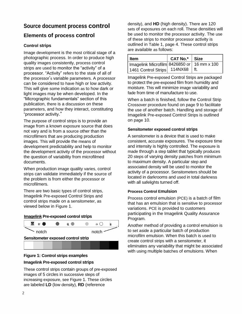
There are two basic types of control strips,
Imagelink Pre-exposed Control Strips and
control strips made on a sensitometer, as
viewed below in Figure 1.
Figure 1: Control strips examples
Imagelink Pre-exposed control strips
These control strips contain groups of pre-exposed
images of 5 circles in successive steps of
increasing exposure, see Figure 1. These circles
are labeled LD (low density), RD (reference
density), and HD (high density). There are 120
sets of exposures on each roll. These densities will
be used to monitor the processor activity. The use
of these strips to monitor processor activity is
outlined in Table 1, page 4. These control strips
are available as follows:
Item CAT No.* Size
Imagelink Microfilm
1461 Control Strips
8426850 or
114NX68
16 mm x 100
ft. Imagelink Pre-exposed Control Strips are packaged
to protect the pre-exposed film from humidity and
moisture. This will minimize image variability and
fade from time of manufacture to use.
When a batch is finished, follow the Control Strip
Crossover procedure found on page 9 to facilitate
the use of another batch. Handling and storage of Imagelink Pre-exposed Control Strips is outlined
on page 10.
Sensitometer exposed control strips
A sensitometer is a device that is used to make consistent, accurate exposures. The exposure time
and intensity is highly controlled. The exposure is
made through a step tablet that typically produces
20 steps of varying density patches from minimum
to maximum density. A particular step and
associated density will be used to monitor the
activity of a processor. Sensitometers should be
located in darkrooms and used in total darkness
with all safelights turned off.
Process Control Emulsion
Process control emulsion (PCE) is a batch of film that has an emulsion that is sensitive to processor
variations. PCE is provided to customers
participating in the Imagelink Quality Assurance
Program.
Another method of providing a control emulsion is
to set aside a particular batch of production
microfilm emulsion. When this batch is used to
create control strips with a sensitometer, it eliminates any variability that might be associated
with using multiple batches of emulsions. When
HD
Imagelink Pre-exposed control strips
notch notch
Sensitometer exposed control strip
RD LD 5092
3
this batch is finished, follow the control strip crossover procedure found on page 9 to use
another batch. “Handling and storage of
pre-exposed or process control emulsion” is
outlined on page 10.
Densitometer
Density is the cornerstone of micrographic processing. The successful use of control strips
depends upon accurate density readings. A
densitometer is a device that transmits light at a
known intensity through a density patch on
microfilm. The light transmitted is received by the
densitometer and the difference of the
transmitted light and the received light is
displayed as a numerical density reading. “Proper use and calibration of a densitometer” can be
found on page 12.
Process control charts
Maintaining a record of density readings from
process control strips is also a key element in proper process control procedures. The analysis
of this data is what provides a true understanding
of the activity or trends associated with a
particular processor. The use of a process control
chart is recommended, as this will provide a
graphic representation of the activity of a
processor. Trends, variations and problems can
be easily displayed and analyzed with the use of
these charts. The “Using process control charts” section can be found on page 10.
Hydrometer
A hydrometer is a device that measures the dilution
(ratio of chemical concentrate to water) of a
solution. Whenever water is added to a chemical,
the “density” of the solution changes in accordance with how much water is added. This density measurement is expressed as the “specific gravity”. This device can be useful to monitor the
dilution accuracy and variations of both the
developer and fixer. The use of a hydrometer is an
important element in a process control procedure
and problem resolution effort. The “Use of a hydrometer” is outlined on page 14.
Source document process control procedures
Establishing aims
A processing aim is the density of a particular sensitometer step or the RD value of Pre-
exposed Control Strips, which will be monitored.
This aim density indicates to an operator that
the processor will produce the same quality
images before production work is processed. If
the aim density varies outside of operating
parameters, steps must be taken by the operator
to get the processor “back in control” before
processing production work.
Establishing “initial aims” is performed for the following reasons:
implementing process control procedures
for the first time
converting to new type of processing chemicals and/or microfilm
a new processor is being put into service
completion of maintenance to a processor
which required the processor tanks to be
emptied
It should also be noted that when establishing initial aims, the following procedure should be
repeated for each processor and closely monitored
for 24 – 48 hours before final initial aim densities
are determined.

4
Table 1: Process control setup for Imagelink Pre-exposed control strips
1. Set processor parameters for Imagelink
Source Document Microfilms. The following parameters are for a deep tank processor (tanks > 5 gal). If a medium or tabletop
processor is used, refer to Imagelink Publication
D-30 for the appropriate parameters.
Suggested starting points: Dilution Specific Gravity
Developer 1:7 1.045 - 1.055
Fixer 1:3 1.080 - 1.105
Dwell Time 48 - 60 seconds
Temperature
C h e m i c a l s 8 5 0 1
W a s h W a t e r 8 0 0 4
Replenishment 16 mm 35 mm 105 mm
Developer 1.0 mL/f 2.0 6.0
Fixer 1.25 mL/ft 2.5 7.5
2. Process 5 pre-exposed control strip exposures.
3. Repeat step 2 multiple times.
4. Process 5 pre-exposed control strips,a
camera exposure step test, consisting of
resolution test targets, white paper and
samples of production documents. Refer to
Figure 2 on page 5.
5. Critique the quality of the documents. Find the
step test exposure that provides acceptable
production quality.
6. Perform an exposure test on all cameras to be used.
7. Repeat steps 1 through 5 for all processors to
be used.
Record the average of the 5 LD, RD, and HD densities. The RD value should be 1.0 to 1.15.
If it is not, adjustments to the dwell time or
temperature of the processor should be made.
The average RD value should be within .06 of each other for each run. When this can be
repeated 5 times, the processor is considered
to be in “initial control”.
Record the exposure setting that puts the white document at 1.0 to 1.15. This density DOES
NOT need to match the RD value.
When the quality is acceptable and the white document density is within tolerance:
the RD value becomes the control aim for
this processor
the white document density is now a reference
for the exposure of that particular camera
If the quality and document densities are unacceptable, make adjustments to the
exposure of the camera(s) to achieve
acceptable results. DO NOT adjust processing
parameters to a camera(s).

5
Process control setup for crossing over control aim to a sensitometer control strip
If a sensitometer is to be used to generate control strips, use the following procedure to cross over the control aim from pre-exposed control strips to sensitometer control strips.
1. Using process control emulsion, make 5 exposures with the sensitometer.
2. Splice together the sensitometer exposures with 5 pre-exposed control strips and process.
3. Make sure the RD value of the pre-exposed control strips is within tolerance.
4. Determine the step on the sensitometer control strip that has the closest density to the RD value
of the pre-exposed control strips without going over.
5. This step and density is now the process control aim.
6. Repeat this procedure 3 times and average the results.
Example:
In the following example, when the image quality of production, resolution and white document densities are acceptable, the daily process control aims are:
Pre-exposed control strips, RD value = .93
Sensitometer strips (PCE) = .87, step 10
IMAGELINK
Pre-exposed
Control Strips
Sensitometer control strips
using Process Control
Emulsion (PCE)
Exposures from
a camera
Figure 2: Daily process control aim examples
H D
=
.93
R D
Step 10 .87
L D
5 0 9 2
Resolution
Targets
White
Documents
Production
= .96

6
Daily checks
Processing control limits
Two sets of limits are used to monitor and control
the processor(s). There is a control limit and a
specification limit. Minor variations are inherent in film and processing and will be evidenced by the
fluctuation in density readings obtained from the
control strips. The two limits account for such
fluctuations and help to determine the appropriate
action to take when these limits are exceeded.
Control limit
The control limit is set at . 06 from the aim. If a
density point falls outside this limit, processor parameters should be checked. Processing can
continue in this condition as long as efforts are
being made to correct the variation.
Specification limits
The specification limit is set at .12 from the aim If
a density point falls outside this limit, processing
should STOP. In the event that this occurs,
process several control strips to validate the
reading in question.
Daily checks
It is recommended that the following
measurements be recorded once for every
eight hours of processing operation.
-Developer tank specific gravity
-Developer replenisher rate
-Wash water temperature (incoming to processor)
-Fixer tank specific gravity
-Fixer replenisher rate
The following should be performed no less than 3
times for every 8 hours of processing operation.
Typically, control strips are spliced to production
work since they are the first to be processed.
1. Record the following on the processor
control chart:
-Date and time
-Processor speed and/or dwell time -
Developer/water temperature
2. Using a sensitometer with process control
emulsion, make 5 exposures and process.
Five Imagelink Pre-exposed Control Strips
can be used separately or in conjunction with
the sensitometer control strips
3. Record the average of the control step of the sensitometer strip and/or the average of the
LD, RD and HD values of the Imagelink Pre-
exposed Control Strips on a process control
chart.
See Figure 4 on page 11 for a control chart with an example of recorded data.
Evaluating results
Immediately after each control strip has been processed, measure the density with a calibrated
densitometer. Read densities in the center of the
steps.
Within control limits: NO ACTION
Outside control limits: Check all processing
variables
Continue to process
Outside spec limits: STOP processing
Repeat control strip test.
Refer to the following tables to determine corrective actions that apply to certain symptoms.
After making any adjustment to the process, the
effect should be monitored with additional control
strips. The adjustment should be noted on the
process control chart.
Resolution / contrast checks
It is also recommended that, on a daily basis, as
part of both a process and image quality control
procedure, resolution targets be monitored from
production microfilmers and processors.
The recommended practice and method of
reading resolution targets is outlined in the ANSI Standard, ANSI/AIIM MS23-2004,
Microfilm of Documents, Operational Procedures/Inspection and Quality Control of
First-Generation Silver- Gelatin.

7
Diagnose and correct an out-of-control process
The following tables will help determine the corrective actions to apply given a certain symptom and
the applicable cause. First, review the "General Processing - All Documents", below, to determine if
any corrective action can be taken. If this doesn't solve the problem, go to the "Conventional
Processing - Source Documents", Table 3.
Table 2: For general processing - all documents
Symptom Possible Causes Corrective Action
Control strip RD and LD Densitometer 1. Check densitometer to be sure that it is properly
density value plots are miscalibration calibrated and zeroed.
outside of control limits 2. Reread the control strip densities to
eliminate reading error as a cause.
3. Examine the Daily Processing Record being kept for
the process to determine if a discrepancy is noted.
4. Process, dry, read and plot another control strip.
If this plots within control limits, it may be that the
readings of the first strip were a result of random
additive conditions. Resume processing.
5. If the second control strip confirms the out-of-
control condition, check your chemicals (specific
gravity), machine conditions (temperature, speed,
dwell time) and condition of the unprocessed
control strips.
6. If all previous checks fail to find the cause of
the out-of-control situation, check the following
table for conventional processing symptoms.
7. If all actions in the following table fails to bring
densities within tolerance, discard the developer
and developer replenisher and mix new solutions.
Follow the procedures in “Set up aim densities
and tolerances” in this document.
8. If necessary, the densitometer correlation strip
provided by the Imagelink Quality Assurance
Laboratory can be used to bring the
densitometer back into calibration.

8
Table 3: For conventional processing - source documents
Symptom Possible Causes Corrective action
LD & RD plots are
too high
• Over-development • Always check another control strip
before attempting correction
High values are repeated • Light Fog • Check handling and safelight after control strip checked • Excessive development time
and/or slow machine speed
conditions
• High development tempera-
ture
• Re-check all processing parameters;
make corrections to these controls
LD is elevated and RD • Check for contamination of • Dump the developer and after
may or may not be developer with fixer cleaning the tanks, replace the
affected • Check for fogging due to developer
unsafe darkroom lighting • Check darkroom lighting conditions
• Possible poor storage
of control strips
• Check storage conditions for
proper humidity levels
RD plot is too low • Short development time • Re-check all processing parameters
and adjust as necessary
• Low developer temperature • Too little or no replenishment
• Fixer contamination
• A processing parameter is
drifting
Control strip values plot within control limits temporarily, then begin to drift out of the control limits again
• Closely monitor all processing
parameters (temperature, speed,
dilution). Adjust as unnecessary.
Check specific gravity of developer.
9
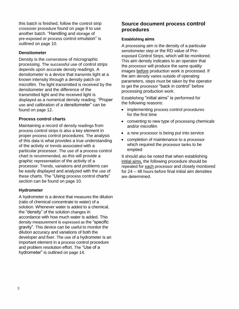
Crossing over new control strips
When a roll of control strips (either pre-exposed or PCE) is nearly exhausted, a new roll should be put
into use. Performing a crossover from the current
control strip batch in use is done because the new
batch of control strip emulsion will not produce
the same densities as the current batch. If a
crossover is not performed, the variations in densities from batch to batch could indicate an
erroneous error condition.
This procedure should be followed to correlate the new control strip density to the old.
1. With existing control strips or Process Control Emulsion, verify the processor is in control and meets current aims. Take corrective action if necessary.
2. Splice together 3 control strips or sensitometer
exposures of the current batch with 3 from the new and process.
3. Measure the density of the RD value of the pre-
exposed control strip or the aim step density of
the sensitometer exposure for both the new and
old strips.
4. Verify that the old batch is within tolerances. The new RD value or sensitometer aim step density is now the new control aim.
5. Perform steps 1 – 4 for each processor in use.
6. This crossover and new densities should be noted on the process control chart and/or a new
chart should be started for each processor.
Old New Old New
IMAGELINK Sensitometer Exposure on
Pre-exposed Process Control Emulsion
Control Strips (PCE)
Figure 3: Cross over using pre-exposed control strips or PCE (process control emulsion)
H D
R D
.93
L D
5 0 9 2
H D
New RD
Aim R D
___ .96
L D
5 0 9 2
New Reference
Aim _____ .89
Step 10
.87
10
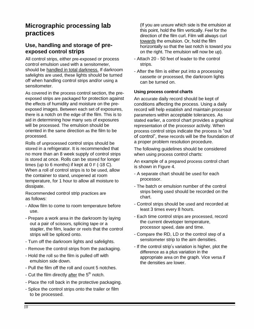
Micrographic processing lab practices
Use, handling and storage of pre- exposed control strips
All control strips, either pre-exposed or process
control emulsion used with a sensitometer,
should be handled in total darkness. If darkroom
safelights are used, these lights should be turned
off when handling control strips and/or using a
sensitometer.
As covered in the process control section, the pre-
exposed strips are packaged for protection against
the effects of humidity and moisture on the pre- exposed images. Between each set of exposures,
there is a notch on the edge of the film. This is to
aid in determining how many sets of exposures
will be processed. The emulsion should be
oriented in the same direction as the film to be
processed.
Rolls of unprocessed control strips should be stored in a refrigerator. It is recommended that
no more than an 8 week supply of control strips
is stored at once. Rolls can be stored for longer
times (up to 6 months) if kept at 0 F (-18 C).
When a roll of control strips is to be used, allow
the container to stand, unopened at room
temperature, for 1 hour to allow all moisture to
dissipate.
Recommended control strip practices are
as follows:
- Allow film to come to room temperature before
use.
- Prepare a work area in the darkroom by laying
out a pair of scissors, splicing tape or a
stapler, the film, leader or reels that the control
strips will be spliced onto.
- Turn off the darkroom lights and safelights.
- Remove the control strips from the packaging.
- Hold the roll so the film is pulled off with emulsion side down.
- Pull the film off the roll and count 5 notches.
- Cut the film directly after the 5th notch.
- Place the roll back in the protective packaging.
- Splice the control strips onto the trailer or film to be processed.
(If you are unsure which side is the emulsion at
this point, hold the film vertically. Feel for the
direction of the film curl. Film will always curl
towards the emulsion. Or, hold the film horizontally so that the last notch is toward you
on the right. The emulsion will now be up).
- Attach 20 - 50 feet of leader to the control
strips.
- After the film is either put into a processing
cassette or processed, the darkroom lights
can be turned on.
Using process control charts
An accurate daily record should be kept of
conditions affecting the process. Using a daily
record will help establish and maintain processor
parameters within acceptable tolerances. As stated earlier, a control chart provides a graphical
representation of the processor activity. When
process control strips indicate the process is “out of control”, these records will be the foundation of
a proper problem resolution procedure.
The following guidelines should be considered
when using process control charts:
An example of a prepared process control chart is shown in Figure 4.
- A separate chart should be used for each
processor.
- The batch or emulsion number of the control strips being used should be recorded on the
chart.
- Control strips should be used and recorded at least 3 times every 8 hours.
- Each time control strips are processed, record the current developer temperature,
processor speed, date and time.
- Compare the RD, LD or the control step of a
sensitometer strip to the aim densities.
- If the control strip’s variation is higher, plot the
difference as a plus variation in the appropriate area on the graph. Vice versa if
the densities are lower.

11
16mm Allen
Conventional Process Control Sheet Processor # Processor M-30
Low Density / D-min (LD)
Aim Density .03 + 0.02 –
0.02 –
.12 –
.06 – +
0 – – .06 –
.12 –
.20 –
Reference Density (RD) .20 –
Control Step
1.13 Aim Density .12
.10 –
+
___ 0 1.81 Aim Density
.10 –
.20 –
For Apr i l 1999
High Density (HD) month/year .20
Time
Proc Speed
Developer: Dev Temp
Water
Emulsion Batch
Date
Dwell Time*
Comments
4 6
a.m.
p.m.
4 7
a.m.
p.m.
4 8
a.m.
p.m.
4 8
a.m.
p.m.
4 10 a.m.
p.m.
4 11 a.m.
p.m.
4 12 a.m.
p.m.
4 13 a.m.
p.m.
4 14 a.m.
p.m.
4 15 a.m.
p.m.
4 16 a.m.
p.m.
4 17 a.m.
p.m.
4 18 a.m.
p.m.
4 19
a.m.
p.m.
420 a.m.
p.m.
4 21
4 22
a.m.
p.m.
4 22
a.m.
p.m.
4 23
a.m.
p.m.
4 24
a.m.
p.m.
4 25
a.m.
p.m.
4 26
a.m.
p.m.
4 28
a.m.
p.m.
a.m.
p.m.
a.m.
p.m.
a.m.
p.m.
a.m.
p.m.
a.m.
p.m.
a.m.
p.m.
a.m.
p.m.
a.m.
p.m.
96 96 96 96 96 96 96 96 96 96 96 96 96 96 96 96 90 96 96 96 96 96 96 48 48 48 48 48 48 48 48 48 48 48 48 48 48 48 48 48 48 48 48 48 48 48 86
0 86
0 90
0 86
0 86
0 86
0 86
0 86
0 86
0 86
0 86
0 86
0 86
0 86
0 86
0 86
0 90
0 90
0 86
0 86
0 86
0 86
0 86
0
840 84
0 84
0 84
0 84
0 84
0 84
0 84
0 84
0 84
0 84
0 84
0 84
0 84
0 84
0 84
0 84
0 84
0 84
0 84
0 84
0 84
0 84
0
8092 8092 8092 8092 8092 8092 8092 8092 8092 8092 8092 8092 8092 8092 8092 8092 8092 8092 8092 8092 8092 8092 8092
wro
ng
tem
pera
ture
wro
ng
spee
d
Developer Mix Ratio 1:7 Repl Rate 96 Fixer Mix Ratio 1:3 Repl Rate 120 Specific Gravity Range 1.045 - 1.055 mL/ft or mL/min Specific Gravity Range 1.080 - 1.105 mL/ft or mL/min
*Determined by timing film speed in the developer or equivalent size tank, top of rack roller-to-roller while running processor.
Figure 4: Example of a one-strip reading per plot

12
- When a control strip crossover is performed or
the processor is cleaned and re-filled with fresh
chemicals, this should be noted on the control
chart with a bold vertical line or a new chart should be started.
- When the aim is changed, start a new process
control chart. Process control charts are
available through EPM by ordering A-1630
for the Conventional Process Control Chart
(as shown in Figure 4) or a COM Process
Control Chart is available as A-1631.
Densitometry
The successful use of control strips depends upon accurate density readings. The densitometer used
must be capable of measuring densities with a
high degree of accuracy and repeatability. The
improper use and maintenance of a densitometer
can indicate erroneous processor conditions,
which could result in undue loss of production.
Proper use and calibration of a densitometer
Recommended densitometry practices are as follows:
- A densitometer should NOT be located in a darkroom.
- The densitometer should be turned on at the
beginning of the day and left on.
- The aperture being used should be the
appropriate size for the reduction ratio being
measured. As a general practice, the largest aperture that can be used for a given image
size provides the best average density of a
document or density patch.
- The densitometer-reading surface should be cleaned once a day with a lint free cloth, lightly
dampened with water.
- Follow the preventative maintenance schedule
provided by the manufacturer.
- Calibrate the densitometer at least once a day.
The densitometer should be calibrated with a
calibration density patch provided by the
manufacturer. If this is not available, a check
plaque such as the Kodak Transmission
Densitometer Check Plaque (CAT. No. 170-
1986), can be used. The density strip provided
by the EPM Quality Assurance Laboratory is a
correlation strip only. This strip is used to
correlate the density reading of the
densitometer to the densitometer in the EPM
Quality Assurance Lab.
- Check the zero of the densitometer before
each reading. Variability in readings can result
from operating the densitometer too hastily.
- Most densitometers require the densities to be
read with the emulsion side up and in the
center of the density patch being measured.
Methylene blue testing
The testing for residual thiosulfate (fixer) is a recommended practice to ensure processing is
performed to image permanence standards. This
test checks that the film is “fixed” and washed
correctly and no silver halide remains on the film which could “print up” over time and obliterate
information. This test procedure and associated
chemicals should never be performed or located near the processing lab area. These chemicals
are very photo-active and can cause severe
contamination of the processor if inadvertently
allowed to migrate into the developer or fixer by
physical contact or other means. If this occurs,
high D-min and/or high density spots will be
observed. The only cure for this is a complete
processor cleaning.
The Residual Thiosulfate level of microfilm is determined by the methylene blue test, which
conforms to the ANSI Standard, ANSI/NAPM
IT9.17-1993 (Photography - Determination of
Residual Thiosulfate and Other Related Chemicals
in Processed Photographic Material - methods
Using Iodine-Amylose, Methylene Blue and Silver
Sulfide.) It is an accurate method for measuring the amount of thiosulfate ion that remains in the
film after processing. See Table 4, page 19, for
instructions on how to do this test.
The amount of residual thiosulfate actually
determined to be present in the film is recorded as
described in Table 4. The clear (minimum density)
portions of the processed film are used for the
methylene blue test. The archival limit is <1.4 micrograms/cm2 S203= (i.e. 1.4 micrograms of
thiosulfate per square centimeter) as established
by ANSI/NAPM IT9.17-1993.

13
Safelights
Safelights are used as a common practice to
provide a safe working environment in either a
dark room or processing environment. The proper
use of safelights is a contributing practice to the production of high quality and consistent images.
The following chart outlines the proper use of
safelights for various microfilms.
Type of film Safelight Bulb*
IMAGELINK HQ,
HD,HS,FS, and
RA Microfilms
Kodak No. 3
Green Filter
7.5 watt
bulb, min.
6 to 8 feet
(1.8 to 2.4
meters)
Imagelink
Duplicating
Microfilms
Kodak No. 1
Red or No. 2
Dark Red Filter
15 watt
bulb, min.
4 feet (1.2
meters)
Imagelink
Direct
Duplicating
Kodak OA
Greenish
Yellow Filter
15 watt
bulb, min.
4 feet (1.2
meters)
Imagelink Diazo,
Vesicular Microfilms Can be used in room light
Imagelink
COM DR &
Ecopos
Microfilm
Kodak No.
1 Red Filter
15 watt
bulb, min.
4 feet (1.2
meters)
*distance from work surface
Chemical mixing and storage
Proper chemical mixing procedures are key
factors in obtaining desirable repeatable results. It
is often difficult to diagnose incorrect or
inconsistent mixed solutions, which may
increase production costs. For best results, follow these recommended practices:
° Mixing equipment that comes in contact with processing solutions should be made of
chemically inert materials. This includes
plumbing, mixing devices and processor filters.
° Always mix chemicals with filtered water at room temperature.
° A 5-micron size filter is recommended for
incoming water filtration. Water quality is very important for proper chemical mixing.
° For safety and proper mixing, implement-
mixing procedures that will add chemicals to
water, not water to chemicals. This reduces
the possibility of chemical concentrates from
splashing on clothes or operator’s skin.
° Thoroughly clean all mixing equipment with water immediately after use. This will prevent
cross contamination when the next solution is
mixed.
° If possible, use different mixing and filling equipment for developer and fixer.
° Provide dust covers for solution storage tanks.
° Whenever possible, protect solutions with floating lids in addition to dust covers.
These lids help to minimize oxidation and
evaporation.
° Check valves should be installed between the
processor and the replenisher unit to help
prevent discharge when either the processor
or replenishment unit is being serviced.
° Only mix and store enough working solution
that will be used in a 72 hour time period.
° All mixed solutions should be stored at room temperature, between 65 and 80 F. Storing
mixed solutions at either too high or low temperatures may cause the chemicals to
become inefficient and produce undesirable results.
° Always keep lids and caps of chemical
concentrate containers on tight and
avoid intermixing the caps or lids.
° Processing equipment must be free from corrosion and chemical deposits. Encrusted
deposits that accumulate can cause chemical contamination and scratches on processed
film. Deposits that are difficult to remove by conventional cleaning can be removed by
using the proper systems cleaner such as
Imagelink Developer System Cleaner (CAT
No. 150-0719) or Imagelink Microclean A (CAT No DC4NYJ1) Imagelink Microclean B
(CAT No DC4NYK3) and Kodak Fixer/Wash
System Cleaner (CAT No. 139-5110).

14
Use of a hydrometer
As stated in the overview section, a hydrometer is a device that measures the dilution (ratio of
chemical concentrate to water) of a solution, see
Figure 5. This measurement is expressed as the
“specific gravity”. This device can be useful to
monitor the dilution accuracy and variations of
both the developer and fixer. The hydrometer can
be used to check the specific gravity directly in
the processor tanks and the holding tanks of the
replenishment system.
Use a hydrometer with a graduated scale range of about 1.0 – 1.220
Turn off the processor recirculating pumps
Place the hydrometer in the processor tank or replenisher holding tank.
The hydrometer will bob and float. When the hydrometer settles, read the graduation at the
solution line to determine the specific gravity.
Solution can also be taken from the processor
tank or replenisher holding tank and put in a
graduated cylinder for reading
Wash off the hydrometer with water after each reading. This will avoid cross contamination.
Specific Gravity Aims
Mix ratio Microfilm Developer
Microfilm Fixer
1:3 n/a 1.085-1.105
1:7 1.045 - 1.055 n/a
Micrographic fundamentals
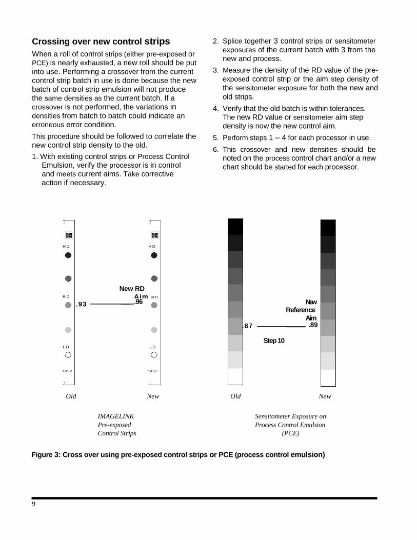
Image capture
As previously stated, image capture devices are adjusted to yield optimum image quality in accordance with the processor(s) that will be used
to develop the image. The function of microfilm
processing is to obtain an image that can be read,
duplicated and possibly copied and/or enlarged. It
is beneficial to have a basic understanding of how
the image is captured and developed.
Simply put, microfilming involves a subject
document, a light source, a lens, a shutter and film. During exposure, the shutter of a camera
opens to allow light to strike the film. Light is projected onto the document. The background of
the document is typically brighter and reflects much more light than the characters of the actual
image to be captured. The reflected light from the background of the document is reflected through
a reduction lens and onto the microfilm. The light that strikes the film turns the silver halide into
microscopic silver metallic specks, invisible to the human eye. So, in actuality, when a document is
microfilmed it is the background of the document that is being photographed. This image is
referred to as the “latent image”. Exposed, yet undeveloped.
1.00
1 .050
Figure 5: Hydrometer example
Exposed area
Latent Image
Reduction
Character "dark area"
Reflected Light
Document
Unexposed area
Background "white area"
Shutter/Aperture
IMAGELINK Microfilm
Light Source
Figure 6: Latent image example

15
Image development
When the microfilm is developed, the chemicals in the developer cause a chemical reaction. The
exposed silver halide (background) is amplified
and turns to black metallic silver, which is now
visible. The unexposed silver halide (characters)
is unaffected. The film is then put in a fixer bath.
Fixer is a chemical (thiosulfate) that dissolves
unexposed and undeveloped silver halide
(characters). The “optimizing” of an image is the
process of determining how much light to use,
which the background of the document will reflect. Therefore, when developed, there is a
“balance” between background density and character clarity.
Develop
Developer is a combination of chemicals that turn exposed silver halide crystals (latent image)
into visible black metallic silver.
Wash
The purpose of the wash is to stop the previous chemical reaction and to clean the film before
entering the next chemical bath.
Fix
Fixer is a chemical (thiosulfate) which dissolves
any undeveloped (unexposed) silver halide.
Wash/rinse
The purpose of the final wash/rinse is to remove
all remaining chemicals that may be left on the
film. This step is critical in achieving proper image permanence. If residual chemicals
remain on the film, the image can deteriorate
over time. (See Image permanence, page 17, for
more information.)
Dry
Proper drying of the film is important as it eliminates any remaining moisture on the film. If
the film is not dried properly, water spots may be
observed. Moisture can also cause the destruction
and/or removal of the emulsion during winding
and unwinding of the film. Figure 7: Typical conventional image development process
Processing
Processing is the development of the latent image
to acceptable standards and treating the film so
that the image will meet image permanence
standards. The processor is the device that will control the development process. Conventional
source document processing is primarily achieved by using two basic chemicals—developer and
fixer. The combined use of the chemicals, along
with water for washing and heat for drying, is what
comprises “processing”. A discussion of the
fundamental process by which most microfilm is
processed follows:
Processor Tanks
D W
F W
E A I A
V S X S
H H
Latent Image (background
exposure)
K Background Unexposed Areas
K

16
Processing parameters
Proper processing and process control is achieved by establishing and monitoring
processing parameters. The film manufacturer
specifies most parameters that will achieve
acceptable film production quality. The
combination of these parameters is often referred
to as "process activity". The activity refers to the
degree to which the film is developed, either high (fast) or low (slow) activity. These parameters are
defined as follows:
Dwell time
The amount of time required to transport the film through a chemical bath or processor tank. Film
manufacturers do not know the type or size of the
processor to be used. Therefore, the manufacturer
will specify the time (dwell) which is required for
proper development of a film. This dwell time will
be later translated into feet per minute according to the processor specifications of path length and
transport speed.
Temperature
The temperature of a chemical, specifically the
developer, will affect how quickly an image will be formed. The temperature cannot be too high or low, as it will directly affect image quality and
all other processor parameters.
Dilution
This is the ratio to which chemical concentrates are added to water. Dilution is expressed in terms
of ratios such as 1:7. This indicates the chemical is
diluted with 1 part concentrate to 7 parts water.
Replenishment
This is the process by which fresh chemical
"working solutions" (diluted) are added to the
appropriate chemical tank in a processor while processing film. The rate at which this is to be
done will be specified by the film manufacturer
and determined by the speed (dwell time) at
which the processor is operating.
Establishing processing parameters example
Use the specification chart provided by the
processor manufacturer to determine developer
and fixer, dwell times and temperature. The
formula below will determine the developer and
fixer replenishment rates (mL/min) by multiplying
transport speed (ft/min) (which is determined by
dividing the path length of the developer tank in feet by the dwell time in seconds and multiplying by
60; see example) and the appropriate processor
replenishment specification (mL/linear ft).
Transport Replenishment/ Replenishment
speed X ft of film = rate (ft/min) (mL/Lft) (mL/min*)
*1 mL/min = 1 cc/min
An example follows:
For processor: Allen M-70
Type of film: 16 mm Imagelink HQ
Dwell: 43 seconds
Dev Film Path: 154 feet
See chemical manufacturer specification table for:
Replenishment (Dev): 1 ml/ft
Replenishment (Fix): 1.25 ml/ft
Note: These are starting point parameters for a deep tank
processor, referred to in Table 1, page 4. For the
replenishment parameters for other deep tank, medium or
tabletop processors refer to the appropriate Imagelink
Dataletter.
Calculated transport speed:
= 215 feet / min
(transport speed)
= 215 mL / min (replenishment rate) Replenishment rate results:
215 feet x 1 = 215 mL/linear foot for developer 215 feet x 1.25 = 268 mL/linear foot for fixer
154 feet x 60 sec
43 sec 1 min
215 feet x 1.0 mL
min feet

17
Interaction of processing parameters
Each processing parameter directly affects image
quality and/or other parameters. The following
chart illustrates the interaction of the parameters.
Parameter: High Low
Dilution light image
(lower density)
dark image
(high D-min)
Temperature dark image
(high D-min)
(high background density)
light image
(low density)
Transport speed light image
(low D-max)
dark image
(high D-min)
Replenishment
Developer: unstable densities
Fixer: waste money
light image
"smoky" film
residual silver
Other considerations
Wash water
The wash water entering a processor should be
filtered and temperature controlled. Typically, the temperature of the wash water should be 50
F (20-
30 C) lower than the developer temperature. In
addition, the rate at which the water flows to the
processor should be monitored and maintained to
the processor manufacturer specifications.
Use of a stop bath
Although not commonly used, a stop bath can
also be used between developer and fixer. The function of the stop bath or rinse (when used) is to
stop development, prevent stains and help preserve the life of the fixing bath. When using an acid stop bath, a certain level of acidity should be maintained.
When Kodak Indicator Stop Bath (CAT No. 146- 4247 - 16 oz or 140-8731 - 1 gal) is used, its
condition can be checked easily because the bath
changes color when exhausted. By room light,
fresh bath is light yellow; it changes to purple-blue when exhausted.
Silver recovery
The recovery of silver from exhausted fixers or
replenishment overflows usually offers monetary savings and other benefits. For more detailed
information concerning silver recovery,.
Drying temperature
The film manufacturer specifies proper drying
temperature. Most processors provide the
capability to adjust the drying temperature. If
multiple film widths are used, the drying
temperature should be adjusted to the setting
that provides proper drying of the widest film.
Image permanence
Most of the film requirements for long-term
storage as recommended by ANSI and ISO
Standards cannot be controlled by the film
manufacturer. They are the responsibility of the
user storing the film. The residual thiosulfate level
of the processed film is the principal factor governed by processing. Satisfactory performance
requires that both fixing and washing be
adequate in order to prevent eventual staining or
image degradation.
If long-term storage is required, residual thiosulfate
levels should be determined by the methylene
blue method. For those who prefer not to do their
own testing, residual thiosulfate testing is available
through Eastman Park Micrographics.
If the pH of the tank solution is less than 4.0, check to see if the stop bath replenishment rate is
too high. If the pH is more than 5.0, check to see
if the replenishment rate is too low or if the
developer carry-over is higher than usual. If
replenishment and carry-over rates are correct,
check the pH of the replenisher solution.

18
Image optimization procedures
for diazo, vesicular and silver microfilm duplication
Diazo duplication
Image formation
Diazo microfilm is a polyester-based film that uses diazonium salts combined with colored
couplers to form a strongly colored dye. Diazo
microfilm is a sign maintaining film. A negative
appearing image is produced from a negative
appearing original. The diazo duplication process
employs a contact printing method. The emulsion
of the silver original is brought in contact with
the emulsion of the diazo microfilm. Ultraviolet light is projected through the base of the original
film. The clear area of the original (characters, D-
min) film passes the ultraviolet light to the diazo
microfilm. Where exposed to the ultraviolet light,
the diazonium salts decompose. When the diazo
film is subjected to heat and ammonia vapors,
the areas protected from ultraviolet light by the
background densities of the original image, will react and the dyes will be released forming the
strongly colored background. The areas where
the diazonium salts decomposed will not release
dyes and this becomes the D-min, or characters
of the diazo duplicate.
As with any development process, controlling the
variables is key to maintaining high image quality
on a consistent basis. See Table 5 for the
procedure on how to optimize the performance
of a diazo duplicator and control the image
development variables.
negative appearing fiche from a positive appearing COM master. Refer to Figure 8 for establishing
crossover aims for vesicular duplicates.
Vesicular duplication is also a contact printing
process. The emulsion of the silver original is brought in contact with the emulsion of the
vesicular film. Ultraviolet light is projected through the base of the original. The clear area of the
original film passes the ultraviolet light to the vesicular film. Where exposed to the ultraviolet
light, the diazonium salts decompose forming nitrogen. When exposed to heat, the plastic layer
softens. The nitrogen expands and forms microscopic bubbles (vesicles). These vesicles are
what create the image (density) by scattering light when projected on a screen. Where no ultraviolet
light hits the film, the film remains unchanged. This
area is “cleared out” causing D-min by re-
exposure to ultraviolet light.
Vesicular duplication
Image formation
Vesicular film is similar to diazo in that this film is
also a polyester-based film that utilizes diazonium
salts. In vesicular film, these salts are coated into
a plastic layer (polymer). Vesicular, however,
does not use dyes or require the use of ammonia
in the image formation process. Vesicular film is
typically used to create a positive appearing
duplicate from a negative appearing original.
Vesicular film is also used in COM to make

19
Table 5: Optimizing diazo image quality procedures
1. Evaluate image quality • D-min - characters clear, hazy, dim
of duplicate • Background density - Use a white document (target)
2. Evaluate background • Blue diazo is less susceptible to development temperature variations color (in a reader)
• For black or tonal diazo microfilms:
- Bluish appearance means temperature is too high
- Brown/sepia appearance means temperature is too low
- Green/yellow appearance means ammonia starvation
3. Temperature sensitive • Apply on diazo film and process strips can also be used
• After processing, read the greatest value temperature box which is darkened
4. Measuring true D-max • Cut an 8" piece of film from a fresh roll of raw film
• Feed 6" into the development chamber
• Allow film to develop 60 - 90 seconds
• D-max should be approximately 1.5 - 1.65 for black and blue
• D-max should be approximately 1.15 - 1.25 for tonal
5. Quantify machine • Record the time required to run a known length of film
speed - Use 100' or 215' roll of camera film
Length of film x 60 = feet /minute
seconds
6. Determining optimal • Duplicate a silver step wedge with known densities .05 - 2.0 (.15
machine speed increments) at various duplicator speeds
• The silver D-min (.05) should reproduce to < .07
• The .35 step should reproduce to .30 - .35 (D-max at optimal machine speed should be 90% of D-max measured in step 4)
6a. Determining optimal • Punch a hole in clear silver original
machine speed • Run the duplicator at normal duplicating speed and duplicate film
Alternate method: with hole
• "Printed D-min" inside of hole should be .01 less in density
than surrounding the hole
• If D-min inside of hole is greater, then reduce transport speed
to compensate for running too fast (low exposure)

20
Vesicular image optimization and control
Vesicular image optimization is systematic. The
only variables in this process are exposure and
heat. The process to establish and maintain
duplicate quality is relatively simple. Also, vesicular image optimization is dependent on the
subject matter and quality of the original image.
In any case, the following simple guidelines can
be useful:
1. Use production master film and perform an
exposure series on the vesicular duplicator.
2. Find the exposure setting that yields the optimum image quality for the application
being duplicated (either positive or negative).
Do this for all the different applications and
reduction ratios to be duplicated on a regular basis.
3. At this setting, duplicate a processed pre-
exposed control strip that falls within processing tolerances. Note the LD and
HD values. These will now become the
control aims for all the duplicators.
4. Duplicate a control strip on all the
duplicators to be used and adjust as
necessary. Repeat this procedure once each
day with a control strip from the processor
generating the Masters.
Note: Densities of vesicular film should be measured with a
densitometer in the projection mode.
Figure 8: Establishing crossover aims for vesicular duplicates

21
Silver duplication
Silver duplicating microfilm uses silver halide as the image formation component and is
constructed much like the camera microfilm used
in standard microfilmers. Silver duplicating
microfilm is used and preferred when the
following attributes are desired:
- very high quality images
- image permanence requirements that meet original silver microfilm Life Expectancy ratings
(LE-500)
- ability to control and manipulate original image polarity, contrast and resolution
- conversion of formats; 16 mm strips to fiche, 35 mm to 16 mm, etc.
- conversion of acetate-based film to polyester- based film
There are two basic types of silver duplicating microfilm — Direct Duplicating and Duplicating
(Print) Microfilm. The Direct Duplicating films
maintain the original image polarity (negative-to-
negative or positive-to-positive). The Print
Duplicating films reverse the original image
(negative-to-positive or positive-to-negative).
Although silver duplicating films function the same
as camera films, they are photographically much
slower and require much more light than typical camera films. Safelights can be used when
handling these films. The appropriate safelights for
these films are discussed on page 13 of this
publication.
Eastman Park Microgrphics offers four different
types of silver duplicating microfilms. Each has a
unique feature that provides high quality and
consistent duplicated images. When images are
duplicated on these films, the contrast of the
image increases in proportion with the contrast of
the duplicating film. Additionally, all Imagelink
Silver Duplicating Microfilms are processed with the same chemicals as Imagelink Camera
Negative Microfilms. However, the processor
conditions do vary from camera film parameters.
A discussion on processing these duplicating
microfilms is found below or refer to Imagelink
Dataletter D-32.
An overview of each duplicating microfilm follows:
Imagelink Direct Duplicating Microfilm
This direct duplicating film has contrast and speed
qualities that provide very high quality duplicates
from most camera film.
Imagelink Direct Duplicating Intermediate
Microfilm
When multiple copies of an original camera microfilm are required, an intermediate master is
used so that the original is protected from
becoming damaged in the duplication process.
This unique film is specially designed with physical and photographic qualities that provide
multiple copies with very high quality. If an
intermediate master is used that has contrast consistent with typical duplicating film, the
resulting image can become too high in contrast
with a loss of resolution. Direct Duplicating
Intermediate Microfilm is a very low contrast film
that enables the contrast of the distribution
duplicate to be closer to the original than if other
typical distribution direct duplicate microfilms
were used as an intermediate.
Imagelink POS Duplicating Microfilm
This film is typically used to make positive appearing images from negative appearing
masters or intermediates. Positive images are
preferred when viewing images with photographs
and when original image appearance is desired.
This film can also be used as an intermediate to
make negative appearing duplicates (negative-to- positive-to-negative), however this is not
recommended.
Imagelink Duplicating Microfilm Positive
Print x440
This film is used for the same purpose as the POS
duplicating film, however, it is lower contrast, faster speed, higher D-max and provides more of
a neutral image tone. This film is preferred when
either poor quality originals or documents with low contrast images require duplication.
Processing of silver duplicating microfilm
The processing parameters for silver duplicating
microfilm differ from the parameters for camera
film. These films use more photographic dyes
and require sufficient washing to remove them.
Therefore, it will require a longer dwell time (slower transport speed) to provide both proper

22
image development and washing. The
recommended dwell times for these films using
deep tank processing are as follows:
Type of microfilm Dwell time*
DD 2470 90 seconds
Pos x440 68 seconds
*These dwell times are recommended starting points only.
The processing parameters for silver duplicating
microfilm being used in a deep tank processor
differs from the parameters for camera negative
microfilms. A longer dwell time is used to provide
proper washing and removal of photographic
dyes. The recommended dwell times for deep tank processors are recommended starting points to
achieve similar photographic properties when
processed in a Imagelink Archive Processor. It
should be noted that when processing a high
volume of microfilms (>25, 30m rolls/day) in a
tabletop processor, increased wash water volume
and/or increased replenishment rates may be
required to reduce residual photographic dye
stain. Also, the developer and fixer tanks should
be cleaned and washed more frequently.
Shorter dwell times can be achieved by adjusting the duplicator exposure and transport speed. If
this is the case, establish LD and RD aims for this
setting using Imagelink pre-exposed or in-house
made control strips. In some cases, it is desired
to use the same processor settings as camera
microfilm. This can be done, however, once
desired processor settings are established. Both
microfilm camera and duplicator exposure
settings should be set to the processor’s
parameters.
Daily checks - Direct Duplicating Microfilm
and Imagelink Direct Duplicating Intermediate
Microfilm
1. Using Imagelink Pre-exposed Control Strips or a sensitometer exposure, ensure the processor activity is within aim tolerances. Do not use duplicating films with a sensitometer. Use a process control emulsion or equivalent. Make adjustments to processor parameters as necessary.
Note: If a different transport speed is used for
duplicating film, set the processor to this speed and
verify processor activity based established aims for this
setting. Make adjustments to processor parameters as
necessary.
Figure 9: Direct Duplicating Microfilm and Intermediate Microfilm setups for establishing aims

23
2. Using the control strip from step 1, duplicate the control strip and process.
3. Check the LD value (D-min) density values:
Direct Dupe: .10 .02 Intermediate: .20 .03
If these densities are not met, make adjustments
to the duplicator exposure until they are within tolerance.
4. Check that the LD, HD or sensitometer
control step densities are within established
control aim densities.
5. Repeat steps 1 – 4 for each duplicator
being used.
The following table, Table 6, is an example that
can aid in the determination of which Direct Duplicating Microfilm to use and to what density the D-min should be printed to, based on the original microfilm image quality.
Print masters
A print master is used when making multiple
duplicates of the original so that the original is
protected from damage in the duplication
process. Also, when an original is of poor quality,
a print master is used to manipulate the image
quality. Imagelink Direct Duplicating Intermediate
Microfilm Intermediate duplicating microfilm is a product designed specifically for this purpose. The
following guidelines, along with Table 6,
should be followed when making print
masters.
When duplicating images, the photographic
contrast of the image will always multiply by
the contrast rating of the duplicating film.
The D-min of the intermediate print master should always be higher than the D-min of the
original. Doing this puts the original image’s
photographic range in the controllable range
of the intermediate film.
The most basic and misunderstood principle
when using Imagelink Direct Duplicating
Microfilm is that exposures should be set to achieve the proper D-min and NOT to achieve
the same image background density of the
original image. Trying to “match background”
densities of the original will compromise the
Table 6: Intermediate microfilms - duplication guidelines
Orig
1N (original) background densities
Light Medium Dark
D-min between frames Film
< .85 D-min aim
.85 - 1.25 Film D-min aim
> 1.25 Film D-min aim
< .08 DD .11 to .13 Intermediate .18 to .22 Intermediate .14 to .18
.09 - .12 DD .13 to .15 Intermediate .18 to .22 Intermediate .14 to .18
.13 - .16 DD .15 to .17 Intermediate .18 to .22 Intermediate .16 to .20
.17 - .20 DD .17 to .19 Intermediate .22 to .24 Intermediate .18 to .22
.21 - .25 DD .19 to .21 Intermediate .26 to .30 Intermediate .20 to .24
NOTE: Use this chart to set the D-min aim when making an intermediate print master.

24
image quality of the ultimate duplicate. As
exposure is increased to bring background densities down, the D-min (characters) “bottom out” and start to bloom or become fat.
Remember, if the original is to be duplicated
and then destroyed, make a proper print
master and do not attempt to exactly replicate
the original.
Establishing aims and daily checks - Imagelink Duplicating Microfilm POS and x440
1. Using Imagelink Pre-exposed Control Strips or a sensitometer exposure, ensure the processor
activity is within aim tolerances. Do not use
duplicating film with a sensitometer. Use a
process control emulsion or equivalent. Make
adjustments to processor parameters, as
necessary.
Note: If a different transport speed is used for
duplicating film, set the processor to this speed
and verify processor activity based on
established aims for this setting. Make
adjustments to processor parameters as
necessary.
this setting. Make adjustments to processor
parameters as necessary.
Using the control strip from step 1 and production
work exposed and processed to the aims, perform
an exposure series on the duplicator and process.
2. The white document density will now be the density that produces the “printed D-min” on
these films. Look for the duplicator setting that
yields a D-min of .06 - .10 from the density of
the white document.
3. At the setting from step 3, critique the image quality of the characters and photographs. If
the image quality is acceptable, the RD and
LD (now D-max) values become the daily
control aims.
4. On a daily basis, duplicate and process a
control strip from a “stable” processor on each
duplicator. Make minor adjustments to the
duplicator exposure to bring the duplicated
control strip aims within tolerance.
In the example below:
Daily Duplicator aims:
Duplicated Control Strip LD aim: 1.4
Duplicated Control Strip RD aim: . 13
(at duplicator setting x)
Figure 10: POS and x440 setup for establishing aims
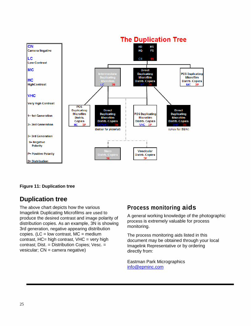
25
Figure 11: Duplication tree
Duplication tree The above chart depicts how the various
Imagelink Duplicating Microfilms are used to
produce the desired contrast and image polarity of
distribution copies. As an example, 3N is showing
3rd generation, negative appearing distribution copies. (LC = low contrast, MC = medium
contrast, HC= high contrast, VHC = very high
contrast; Dist. = Distribution Copies; Vesc. =
vesicular; CN = camera negative)
Process monitoring aids A general working knowledge of the photographic
process is extremely valuable for process monitoring.
The process monitoring aids listed in this
document may be obtained through your local
Imagelink Representative or by ordering directly from:
Eastman Park Micrographics [email protected]

26
Epminc.com
Kodak is a trademark of Eastman Kodak
Company
Imagelink is a trademark of Eastman
Park Micrographics