control solution accessories · control solution 01 draft energy estimation lats energy lats energy...
TRANSCRIPT

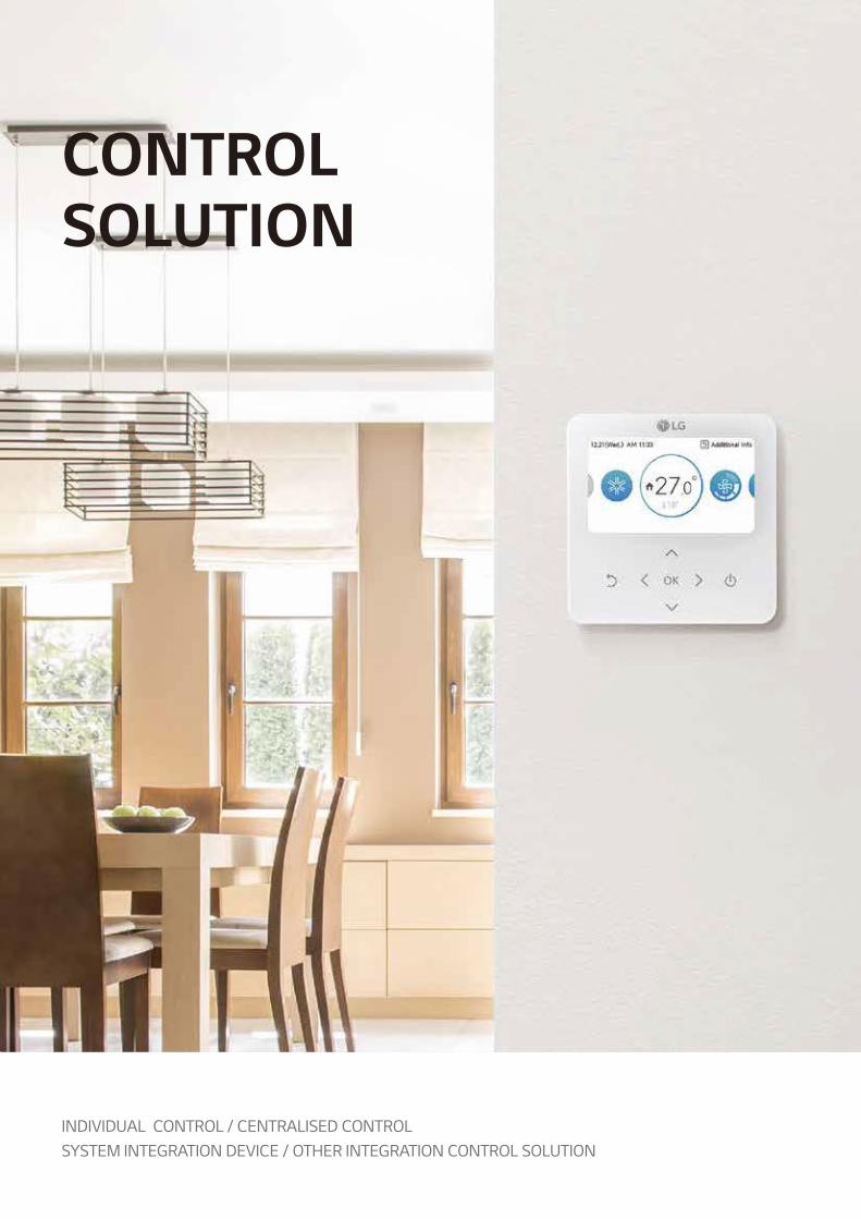
CON
TROL
SOLU
TION
1LG Multi V 5 Air Conditioners - Control Solution & Accessories
LG HVAC SOLUTION
INDOOR UNITS
CONTROL SOLUTION
ACCESSORIES

ENGINEERING CAPABILITY :HVAC TOOL & SUPPORT
From planning to service & maintenance and then to de-construction, an architectural project goes along many stages from the beginning to the end of its lifecycle. Along those stages, various engineering tools are applied to solve the diverse issues happening in each stage, with the most optimal solution possible. Due to the usage of such tools, buildings are effectively designed, built, supervised, and maintained throughout the lifecycle.Dedicated to provide exceptional HVAC engineering support, LG Electronics Air-Solution Business Unit offers several engineering tools and solutions focused on HVAC, during the overall lifecycle of a building, related to the three categories: I. Draft Energy Estimation, II. Model Selection & Design, and III. Installation Environment Simulation. Among them, the LATS* Program series has been developed to offer optimised tool for LG HVAC systems, providing our customers a fast, easy, and accurate way in everyday duties of Model-selection, Draft Energy Estimation & Designing, and many more.
* LATS : LG Air-conditioner Technical Solution
II
Model Selection & Design
I
Energy Estimation
III
InstallationEnvironment Simulation
LATSENERGY
LATSHVAC
LATS CADLATS REVIT
CFD
Planning01
Schematic Design02
Construction Design04
Design Development03
Construction05
Service & Maintenance06
2

CON
TROL
SOLU
TION
01 Draft Energy EstimationLATS EnergyLATS Energy program is a draft energy estimation program, self-developed by LG. This program helps estimate the draft energy usage and analyses the life cycle cost of LG VRF models during the early stage of a project.
02 Model SelectionLATS HVACLATS HVAC is an integrated model selection program of LG HVAC products, enabling an accurate and quick selection on the best model suitable to each sites. In addition to model selection, faster estimation on refrigerant piping diameter and additional refrigerant is possible, along with auto printing of reports.
04 Installation Environment SimulationCFD AnalysisCFD Analysis is applied in areas of estimating: indoor airflow and temperature distribution while operating VRF products, outdoor airflow distribution, and noise level. By running a simulation before construction, engineers estimate possible issues and find optimal solutions of malfunction that could occur after construction.
03 DesignLATS CADLATS CAD enables faster and a more accurate design of LG HVAC products. Moreover, it offers not only designing, but also quotation and installation review in order to minimise problems during installation processes.
LATS RevitLATS REVIT is developed to make 3D designing of LG HVAC products easier than the previous program. It enables engineers to check 3D images from designing stage and prevents possible issues of the installation stage.
3LG Multi V 5 Air Conditioners - Control Solution & Accessories

HOTEL
Hotel Room Solution
APARTMENT
Power Distribution Solution
54kW
36kW
24kW
Integration Solution
LG CONTROL SOLUTION
*2016 AC Manager 54

CON
TROL
SOLU
TION
SMALL BUILDING
Small Central Control Solution
RESIDENTIAL
Smart Individual Control Solution
· External Device
Lighting Pump Fan Temp. SensorCO2 Sensor
· Energy Management
3rd Party BMSService/Maintenance
OFFICE
Central Control Solution
CON
TROL
SOLU
TION
· Energy Management
3rd Party BMSService/Maintenance
OFFICE
Central Control Solution
SMALL BUILDING
Small Central Control Solution
RESIDENTIAL RESIDENTIAL
Smart Individual Control Solution
· External Device
Lighting Pump Fan Temp. SensorCO2 Sensor
MULTI V 5 offers a diverse range of effective control solutions that satisfy specific needs of each building and its user scene. These controlling systems are equipped with user friendly interface, flexible interlocking environment, energy management and smart individual controller for optimised controlling conditions and smart building management.
5LG Multi V 5 Air Conditioners - Control Solution & Accessories

8
10
20
31
40
LG HVAC CONTROL LINE-UP
INDIVIDUAL CONTROL
CENTRALISED CONTROL
SYSTEM INTEGRATION DEVICE
OTHER INTEGRATION CONTROL SOLUTION
10 - 63
CONTROL SOLUTION
66
74
MECHANICAL ACCESSORIES
PIPING ACCESSORIES
64 - 89
ACCESSORIES
INDEX
6
CON
TROL
SOLU
TION
CONTROL SOLUTION
INDIVIDUAL CONTROL / CENTRALISED CONTROLSYSTEM INTEGRATION DEVICE / OTHER INTEGRATION CONTROL SOLUTION

Individual Control Centralised ControlWired Remote Controller Wireless Remote
ControllerIndoor Unit
~ 32Indoor Unit
~ 128Indoor Unit
~ 8,192Premium Standard Simple
Standard III (White) AC Ez AC Smart IV AC Manager 5
PREMTA000 PREMTB100 PQRCVCL0QW PQWRHQ0FDB PQCSZ250S0 PACS4B000 PACM5A000
Standard II (White) AC Smart 5
PREMTB001 PQRCHCA0QW(Simple for Hotel)
PACS5A000
Wi-Fi controller Indoor Unit~ 64
Indoor Unit~ 256
LG Wi-Fi Modem AC Ez Touch ACP IV
For Indoor UnitPWFMDD200
PACEZA000 PACP4B000
LG Wi-Fi Modem ACP 5
For Indoor UnitLG-RC-WF-1
PACP5A000
For Indoor UnitLG-IR-WF-1
*AC Smart IV & AC Smart BACnet will be replaced by AC Smart 5*ACP IV & ACP BACnet will be replaced by ACP 5*KNX Gateway is provided by INTESIS
CONTROL SOLUTION
LG HVAC CONTROL LINE-UP
8

CON
TROL
SOLU
TION
Centralised Control Other Integration DeviceSystem Integration Device Indoor Unit
Outdoor Unit AHU KitFacility Integrator Gateway for Protocol PI-485 Dry Contact Control Accessory
PDI(Power Distribution Indicator) AC Smart BACnet PI-485 Group Control Wire
IO Module(Input / Output Module) Communication Kit
Premium (8port)PQNUD1S40
Standard (2port) PPWRDB000
PBACNA000 For SINGLE /MULTI / THERMA V
PMNFP14A1
Simple Dry ContactPDRYCB000
PZCWRCG3 Demand ControllerFor MULTI V IV/5
PVDSMN000
Return/Room Air controlPAHCMR000
ACS I/O Module(Input / Output Module) ACP BACnet
RemoteTemperature Sensor
Dry Contact forDemand Control Communication Kit
PEXPMB000 PQNFB17C0 For Indoor Unit (Air-Conditioner, ERV)
PHNFP14A0
2 Points Dry Contact(For Setback)PDRYCB400
PQRSTA0 Demand Controller for MULTI V III
PQDSBCDVM0
Discharge Air controlPAHCMS000
Chiller Option Kit ACP Lonworks Zone ControllerVariable Water Flow
Control kit Control kit
PCHILLN000 PLNWKB000 Dry Contact for ThermostatPDRYCB300
4 Zones by thermostat ABZCA
For MULTI V WATER IVPWFCKN000
PRCKD21E (~ 4 ODUs)PRCKD41E (~ 8 ODUs)
Modbus RTU Gateway LG Wi-Fi Modem
EEV Kit(Electronic Expansion Valve)
PMBUSB00A For ModbusPDRYCB500
For MULTI V WATER IIPRVCO
PRLK048A0 (~ 28 kW)PRLK096A0 (~ 56 kW)
KNX Gateway Low Ambient KitTXV Kit
(Thermal Expansion Valve)
LG-AC-KNX4LG-AC-KNX8
LG-AC-KNX16LG-AC-KNX64
For MULTI V IVPRVC2
PATX13A0E (22.4 ~ 44.8 kW)PATX20A0E (50.4 ~ 72.8 kW)
PATX25A0E (78.4 ~ 100.8 kW)PATX35A0E (106.4 ~ 128.8 kW)PATX50A0E (134.4 ~156.8 kW)
Cool / Heat Selector
PRDSBM
9LG Multi V 5 Air Conditioners - Control Solution & Accessories

INDIVIDUALCONTROL SOLUTION

CON
TROL
SOLU
TION
Standard III WiredRemote controller
Premium WiredRemote Controller
Standard II WiredRemote Controller
Simple Wired Remote Controller
Wireless Remote Controller
Wi-Fi Controller
Model Name PREMTA000 PREMTB100PREMTBB10
PREMTB001PREMTBB01
PQRCVCL0QWPQRCVCL0Q
PQRCHCA0QWPQRCHCA0Q
PQWRHQ0FDB PWFMDD200
On / Off • • • • • •
Mode Change • • • •* • •
Temperature Setting • • • • • •
Fan Speed Control • • • • • •
Auto Swing • • • •* • •
Vane Control(Louver Direction)
• • • •* • •
Additional Mode Setting • • • • • -
E.S.P(External Static Pressure)
• • • • - -
Reservation Weekly / Yearly Weekly / Yearly Weekly - Sleep, On / Off Weekly On / OffChild lock / Total Lock • • • • - -
Advanced Lock(on/off, mode, set point range)
• • Mode only - - -
Electric Failure Compensation • • • •* - •
Time Display • • • - - -
Filter Sign • • • - - •
Energy Monitoring** • • • - - •
2 Set Points Control • • - - - -
External Ports - DO 1 - - - -
Remote Controller Line Up
• Indoor unit needs to have functions requested by the controller* PQRCHCA0QW / PQRCHCA0Q doesn’t offer this function** LG centralised controller(available from AC Ez Touch or higher model) with PDI (PQNUD1S40 / PPWRDB000) installation is required for this function
11LG Multi V 5 Air Conditioners - Control Solution & Accessories
INDIVIDUAL CONTROL SOLUTION
LINE-UP

The Optimized Controller in MULTI V 5- Humidity sensor embedded- Comfort cooling setting- Smart Load Control setting- Outdoor unit low noise setting- Defrost mode setting
New Modern Design & Easy interface- Seamless design / Touch button- 4.3 inch Color LCD / Intuitive GUI
Features 1)
External Device On/Off- Customized Interlocking control with indoor status
2 Set Points control 2)
Multi Language supportEnglish, French, German, Spanish, Italian, Portuguese, Polish, Czech, Russian, Chinese
*It might not be indicated or operated at the partial product** This function is available for certain indoor unit type*** LG centralised controller(available from AC Ez Touch or higher model) with PDI (PQNUD1S40 / PPWRDB000) installation is required for this function1) Indoor unit needs to have functions requested by the controller2) 2 set points control works normally with MULT V Heat Recovery and Single Split Heat Pump. But in case of MULTI V Heat Pump, It may not work properly
Model Name PREMTB100
On / Off •
Fan Speed Control •
Temperature Setting •
Mode Change Cooling / Heating / Auto / Dehumidification / Fan
Additional Mode Setting* Plasma Purification / Energy-Saving Cooling / Robot Cleaning / Heater / Humidification / Comfort Cooling
Auto Swing •
Vane Control (Louver direction) •
E.S.P (External Static Pressure)** •
Reservation Simple / Sleep / On & Off timer / Weekly / Yearly / Holiday
Time Display •
Electric Failure Compensation •
Lock All / On & Off / Mode / Set temperature range
Filter Sign • (Remain time + Alarm)
Energy Management Check Energy Usage*** / Check Operation Time / Target Setting (Energy, Operation Time) / Time Limit Operation / Alarm Popup / Initialization Usage Data
Operation Status LED •
Indoor Temperature Display •
Indoor Humidity Display •
Display 4.3 inch TFT color LCD (480 x 272)
Size (W x H x D, mm) 120 x 120 x 16
Black light for Screen saver •
Home Leave 2 set points control
4.3 inch Color screen with a modern design
PREMTB100 (White)
INDIVIDUAL CONTROL SOLUTION
STANDARD III WIRED REMOTE CONTROLLER
12

CON
TROL
SOLU
TION
Fully Support MULTI V 5 functions Inside Dual SensingStandard III remote controller can do sensing both Temperature and Relative Humidity.
Comfort CoolingWithout cooling operation stopping, this function allows MULTI V 5 IDU to maintain operation at mild cooling mode.
External Device On/OffCustomised Interlocking Control User can make control scenario.example) When temperature is under 10 degree, turn on the external heater.
External Equipment ControlUser can turn on or off the external equipment
through contact point output.
Colorful IconStandard III remote controller is possible to express various colors.
Weekly / Monthly / Yearly Trend & Target Setting controlStandard III remote controller provides convenient trend & target graph for different period.
Easy Checking ScheduleStandard III remote controller provides clock type daily schedule.
Modern Design & Intuitive Interface
Cool Heat Dry Fan Auto
2 Set Points Control
Cooling set pointfor Unoccupied
Unoccupied
IndoorTemperature
OccupiedHeating Set Point
for Occupied
Cooling Set Point for Occupied
Heating Set Pointfor Unoccupied
Arrive at a room
Thermo-Off
Leave a room
Cooling Heating
Temperature
Time
Cooling
Heating
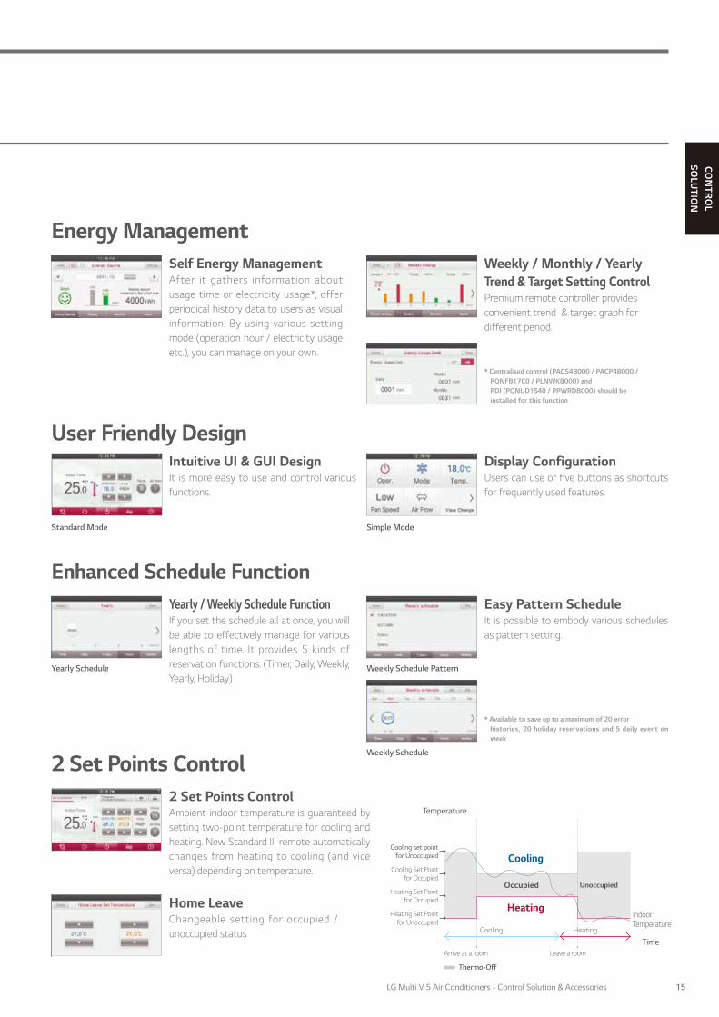
2 Set Points ControlAmbient indoor temperature is guaranteed by setting two-point temperature for coolingand heating. Standard III remote controller automatically changes from heating to cooling (and vice versa) depending on temperature.
Home LeaveChangeable setting for occupied / unoccupied status
13LG Multi V 5 Air Conditioners - Control Solution & Accessories

*It might not be indicated or operated at the partial product** This function is available for certain indoor unit type*** LG centralised controller(available from AC Ez Touch or higher model) with PDI (PQNUD1S40 / PPWRDB000) installation is required for this function**** For ceiling type duct4) Indoor unit needs to have functions requested by the controller5) 2 set points control works normally with MULT V Heat Recovery and Single Split Heat Pump. But in case of MULTI V Heat Pump, It may not work properly
Model Name PREMTA000 / PREMTA000A / PREMTA000B
On / Off •
Fan Speed Control •
Temperature Setting •
Mode Change Cooling / Heating / Auto / Dehumidification / Fan
Additional Mode Setting* Plasma Purification / Energy-Saving Cooling / Robot Cleaning / Heater / Humidification
Auto Swing •
Vane Control (Louver direction) •
E.S.P (External Static Pressure)** •
Reservation Simple / Sleep / On / Off / Weekly / Yearly / Holiday
Time Display •
Electric Failure Compensation •
Child Lock •
Filter Sign • (Remain time + Alarm)
Energy Management Check Energy Usage*** / Check Operation Time / Target Setting (Energy, Operation Time) / Time Limit Operation / Alarm Popup / Initialization Usage Data
Operation Status LED •
Indoor Temperature Display •
Wireless Remote Controller Receiver •****
Display 5 Inch TFT color LCD (480 x 272)
Size (W x H x D, mm) 137 x 121 x 16.5
Black Light for Screen Saver •
Home Leave 2 Set Points Control
Self-Management for Energy Saving- Time limit operation / Power consumption monitoring- Weekly / Monthly / Yearly trend tracking- Target alert alarm- Temperature range setting
Design with User’s Convenience- Full touch / Intuitive GUI (Graphic User Interface)- Main display simple mode / Touch buzzer
Features 4)
Improved Scheduling- Timer / Daily / Weekly / Yearly / Holiday
2 Set Points Control 5)
5 inch full touch screen with a premium design
PREMTA000
INDIVIDUAL CONTROL SOLUTION
PREMIUM WIRED REMOTE CONTROLLER
14
CON
TROL
SOLU
TION
Cooling set pointfor Unoccupied
Unoccupied
IndoorTemperature
OccupiedHeating Set Point
for Occupied
Cooling Set Point for Occupied
Heating Set Pointfor Unoccupied
Arrive at a room
Thermo-Off
Leave a room
Cooling Heating
Temperature
Time
Cooling
Heating
2 Set Points Control2 Set Points ControlAmbient indoor temperature is guaranteed by setting two-point temperature for cooling and heating. New Standard III remote automatically changes from heating to cooling (and vice versa) depending on temperature.
Home LeaveChangeable setting for occupied / unoccupied status
Enhanced Schedule FunctionYearly / Weekly Schedule FunctionIf you set the schedule all at once, you will be able to effectively manage for various lengths of time. It provides 5 kinds of reservation functions. (Timer, Daily, Weekly, Yearly, Holiday)
Yearly Schedule
* Available to save up to a maximum of 20 errorhistories, 20 holiday reservations and 5 daily event on week
Weekly Schedule
Easy Pattern ScheduleIt is possible to embody various schedules as pattern setting.
Weekly Schedule Pattern
Energy ManagementSelf Energy ManagementAfter it gathers information about usage time or electricity usage*, offer periodical history data to users as visual information. By using various setting mode (operation hour / electricity usage etc.), you can manage on your own.
Weekly / Monthly / Yearly Trend & Target Setting ControlPremium remote controller providesconvenient trend & target graph for different period.
* Centralised control (PACS4B000 / PACP4B000 / PQNFB17C0 / PLNWKB000) and PDI (PQNUD1S40 / PPWRDB000) should be installed for this function
User Friendly DesignIntuitive UI & GUI DesignIt is more easy to use and control various functions.
Standard Mode
Display ConfigurationUsers can use of five buttons as shortcuts for frequently used features.
Simple Mode
15LG Multi V 5 Air Conditioners - Control Solution & Accessories

Features1)
STANDARD II
* For ceiling type duct** LG centralised controller(available from AC Ez Touch or higher model) with PDI (PQNUD1S40 / PPWRDB000) installation is required for this function1) Indoor unit needs to have functions requested by the controller
Model Name PREMTB001
On / Off •
Fan Speed Control •
Temperature Setting •
Mode Change Cooling / Heating / Auto / Dehumidification / Fan
Additional Mode Setting Plasma Purification / Energy-Saving Cooling / Robot Cleaning / Heater / Humidification
Auto Swing •
Vane Control (Louver direction) •
E.S.P (External Static Pressure) •
Reservation Simple / Sleep / On / Off / Weekly / Holiday
Time Display •
Electric Failure Compensation •
Child Lock •
Filter Sign • (Remain time + Alarm)
Operation Status LED •
Indoor Temperature Display •
Wireless Remote Controller Receiver •*
Size (W x H x D, mm) 120 x 121 x 16
Blacklight •
Power Consumption Monitoring •**
Check Model Information •
Providing easy control of one or a group of indoor units with various functions
PREMTB001 (White)
INDIVIDUAL CONTROL SOLUTION
STANDARD II WIRED REMOTE CONTROLLER
16

CON
TROL
SOLU
TION
Features1)
Simple Simple for Hotel
* For ceiling type duct1) Indoor unit needs to have functions requested by the controller
Model Name PQRCVCL0QW PQRCHCA0QW
On / Off • •
Fan Speed Control • •
Temperature Setting • •
Mode Change Cooling / Heating / Auto / Dehumidification / Fan Only Changeable by Central Controller
Auto Swing • -
Vane Control (Louver direction) • -
E.S.P (External Static Pressure) • •
Electric Failure Compensation • -
Child Lock • •
Indoor Temperature Display • •
Wireless Remote Controller Receiver •* •*
Size (W x H x D, mm) 70 x 121 x 16 70 x 121 x 16
Blacklight • •
A simple way to control office or hotel systems in a compact design
SIMPLE
SIMPLE FOR HOTEL
PQRCVCL0QW (White)
PQRCHCA0QW (White)
INDIVIDUAL CONTROL SOLUTION
SIMPLE WIRED REMOTE CONTROLLER
17LG Multi V 5 Air Conditioners - Control Solution & Accessories

FeaturesModel Name PQWRHQ0FDB
On / Off •
Fan Speed Control •
Temperature Setting •
Mode Change Cooling / Heating / Auto / Dehumidification / Fan
Additional Mode Setting Plasma Purification / Energy-Saving Cooling / Robot Cleaning / Auto Dry
Auto Swing •
Vane Control (Louver direction) •
Reservation Sleep / On / Off
Indoor Temperature Display •
Sleep Mode Auto Max. 7 hours
Size (W x H x D, mm) 51.4 x 153 x 26
PQWRHQ0FDB
INDIVIDUAL CONTROL SOLUTION
WIRELESS REMOTE CONTROLLER
18

CON
TROL
SOLU
TION
Features
Overview
Model Name PWFMDD200
Size (W x H x D, mm) 48 x 68 x 14
Interfaceable Products Multi V Indoor unit 3)
Connection Type Indoor unit 1:1
Communication Frequency 2.4 GHz
Wireless Standards IEEE 802.11b/g/n
Mobile Application LG SmartThinQ(Android v4.1(Jellybean) or higher, iPhone iOS 9.0 or higher)
Optional Extension Cable PWYREW000 (10m extension)
Control LG air conditioners via using the internet devices as Android or iOS bases smartphones.
• Access LG air conditioner anytime and from anywhere with iOS or Android compatible devices
• LG’s exclusive Home Appliances control app(SmartThinQ) is available• Simple operation for various functions
- On/Off - Operation Mode - Current/Set Temperature- Fan Speed - Vane Control 2) - Reservation (Sleep, Weekly On/Off)- Energy Monitoring 1) - Filter Management - Error check
* Functionality may be different according to each IDU model* User interface of application shall be revised for its design and contents improvement* Application is optimized for smartphone use, so it may not be well functioning with tablet devices1) LG Centralised controller and PDI installation is required for this function2) Vane Control may not be possible according to the type of Indoor unit3) For the compatibility with Indoor unit, please contact regional office
* Search “LG SmartThinQ” on Google market or Appstore then download the app. * Internet service with Wi-Fi connection has to be available
Controlling& Monitioring
Reservation Energy Monitoring
Wi-Fi Modem
USB Wire
ThinQ Server
LG SmartThinQ
PWFMDD200
INDIVIDUAL CONTROL SOLUTION
LG WI-FI MODEM
19LG Multi V 5 Air Conditioners - Control Solution & Accessories

CENTRALISED CONTROL SOLUTION
20

CON
TROL
SOLU
TION
* This function is available for certain product
Central Controller Line Up
AC Ez Touch
AC Smart 5AC Smart IV
AC Ez
ACP 5ACP IV
AC Manager 5
Model Name PQCSZ250S0 PACEZA000 PACS5A000PACS4B000
PACP5A000PACP4B000 PACM5A000
Maximum number of units 32 64 128 256 8,192
Individual / Group Control • • • • •
Individual Controller Lock • • • • •
Error Check • • • • •
Slave Mode(Interlocking with higher level controller) • • • - -
Schedule Weekly Yearly Yearly Yearly Yearly
Remote Access - By client S/W Web Web Web
Emergency Stop & Alarm Display - • • • •
Power Consumption Monitoring (with PDI) - • • • •
Auto Changeover / Setback - • • • •
Temperature Limit - • • • •
Operation Time Limit - - • • •
Visual Navigation - - • • •
Operation Trend - - • • •
Interlock Control - - • • •
Virtual Group Control - - • • •
ODU Capacity Control* - - • • •
Energy Navigation (with PDI) - - • • •
ACS IO Module Interlocking - - • • •
BMS Integration (BACnet, Modbus protocol)
- - • (PACS5A000 only) • (PACP5A000 only) -
IPv6 Support - • • (PACS5A000 only) • (PACP5A000 only) -
CENTRALISED CONTROL SOLUTION
LINE-UP
21LG Multi V 5 Air Conditioners - Control Solution & Accessories

All-in-One solution for BMS integration up to 128 units via BACnet and Modbus protocol as well as its own smart management function with touch screen interface
PACS5A000
Features
Installation Scene
Model Name PACS5A000Size (W x H x D, mm) 253.2 x 167.7 x 28.9
Interfaceable Products MULTI V / ERV / ERV DX / Hydro kit / THERMA V / AHU kit / LG Chiller1)
Maximum number of units 128
Individual / Group Control On & Off / Mode / Temperature / Fan speed
Individual Controller Lock Temperature / Mode / Fan speed / All
Advanced Function Setting and Display 2) Comfort Cooling / ODU Low Noise / ODU Defrost Mode / Comfort Level display / CO
2 Level display (for ERV/ERV DX) / Night Time Free Cooling (for ERV/ERV DX)
Error Check •
Slave Mode (Interlocking with higher level controller) •
Schedule Weekly / Monthly / Yearly / Exception day
Web Access •
Emergency Stop & Alarm Display •
Power Consumption Monitoring (with PDI) •
Auto Changeover / Setback •
Temperature Limit •
Operation Time Limit •
Visual Navigation •
Operation Trend •
Interlock Control •
Virtual Group Control •
ODU Capacity Control •
Energy Navigation (with PDI) •
Daylight Saving Time •
ACS IO Module Interlocking Max. 9
External IO Port DI 2 / DO 2
BMS Integration 3) BACnet IP / Modbus TCP
IPv6 Support •
1) Chiller Option Kit(PCHLLN000) is required 2) It is only available in some products 3) For the detail point list, please refer to the installation manual
Internet
Remote access
• AHU Control Kit• AHU Comm. kit
(PAHCMS000)
OR
• MULTI V 5 • MULTI V IV• MULTI V III • MULTI V II
• MULTI V S• MULTI V Mini• MULTI V SPACE II
• MULTI V WATER IV
• MULTI V WATER II
• ERV• MULTI SPLIT• SINGLE SPLIT
CH2
CH1
ACS IO MODULE
• Appropriate PI485GW installation according to PDB is necessary
Ethernet
BMS
CENTRALISED CONTROL SOLUTION
AC SMART 5
22

CON
TROL
SOLU
TION
Features
Energy ManagementEnergy navigation function allows air conditioners operation to be managed under the monthly plan of energy usage. By analyzing present energy consumption and comparing with the plan, overuse of system operational costs can be prevented.
Device InterlockBuilding Facility can be interlocked with LG HVAC system on the automated control logic.
BMS IntegrationWithout additional device, AC Smart 5 provides BACnet/IP and Modbus TCP/IP interface for BMS(Building Management System) integration as well as its own management function.
Advanced Network Accessibility AC Smart 5 reflects the state of the art of network technology trend. IPv6(Internet Protocol version 6), which is the most recent version of the Internet Protocol, provides accessibility to the IPv6 compatible network environment. HTML5 makes the web access to AC Smart 5 easier and look good on all devices, especially for mobile.
Visualised ControlVisual navigation enables controlling and monitoring the unit on floor plan view for the intuitive management.
Operation TrendUnit’s operation status change in the past can be traced to help establishing reasonable operation plan of the site.
BACnet over IP
IPv6 Network
HTML5 web design
BMS
23LG Multi V 5 Air Conditioners - Control Solution & Accessories

PACEZA000
Smart management with 5 inch touch screen for small site
Internet
• MULTI V 5• MULTI V IV• MULTI V III• MULTI V II
• MULTI V S• MULTI V Mini• MULTI V SPACE II
• MULTI VWATER IV
• MULTI VWATER II
• ERV• MULTI SPLIT• SINGLE SPLIT
• Appropriate PI 485 should be used according to PDB
FeaturesModel Name PACEZA000Size (W x H x D, mm) 137 x 121 x 25
Interfaceable Products MULTI V / ERV / ERV DX / Hydro kit / THERMA V
Maximum number of units 64
Individual / Group Control On & Off / Mode / Temperature / Fan speed
Individual Controller Lock Temperature / Mode / Fan speed / All
Error Check •
Slave Mode (Interlocking with higher level controller) •
Schedule Weekly / Monthly / Yearly / Exception day
Remote Access By client S/W
Emergency Stop & Alarm Display •
Power Consumption Monitoring (with PDI) •
Auto Changeover / Setback •
Temperature Limit •
Operation History Error
ODU Low Noise1) •
Daylight Saving Time •
External IO Port DI 1
IPv6 Support •
1) It is only available in some products
Installation Scene
CENTRALISED CONTROL SOLUTION
AC EZ TOUCH
24

CON
TROL
SOLU
TION
Internet
Features
Energy ModeWhen using energy mode function, operation mode changes from cooling to fan or heating to off mode by force. (It is available only air conditioner and ‘on’ mode indoor unit)
Alarm IndicatorIt works when there are some errors or it’s time to change the filter. Users can respond immediately according to alarm indicator therefore HVAC system is monitored consistently.
PC AccessUsers can control each space efficiently through PC access.
Energy Statistics (with PDI)Statistics of operational status (time, power consumption) are provided to help make intelligent system operation decisions.
ScheduleSchedule control allows user to set the events in advance to maximise system performance. Also, by blocking unnecessary operation, it prevents a waste of energy.
Group / Individual ControlAccording to the situation, it can be controlled by group or each indoor unit. It is useful to monitor or control for the best fit of request.
*IPv6 supported
25LG Multi V 5 Air Conditioners - Control Solution & Accessories

PACS4B000
Large 10.2 inch touch screen with intuitive GUI (Graphic User Interface) allows easy control
Features
1) Chiller Option Kit (PCHLLN000) is required2) Assignment of public IP address is required to access central controller through internet please contact regional office to have detailed Internet connection configuration
Model Name PACS4B000Size (W x H x D, mm) 253.2 x 167.7 x 28.9
Interfaceable Products MULTI V / ERV / ERV DX / Hydro Kit / THERMA V / AHU Kit / LG Chiller 1)
Maximum number of units 128
Individual / Group Control On & Off / Mode / Temperature / Fan Speed
Individual Controller Lock Temperature / Mode / Fan speed / All
Error Check •
Slave Mode (Interlocking with Higher Level Controller) •
Schedule Weekly / Monthly / Yearly / Exception day
Web Access 2) •
Emergency Stop & Alarm Display •
Power Consumption Monitoring (with PDI) •
Auto Changeover / Setback •
Temperature Limit •
Operation Time Limit •
Visual Navigation •
Interlock Control •
Virtual Group Control •
ODU Capacity Control •
Energy Navigation (with PDI) •
Daylight Saving Time •
ACS IO Module Interlocking Max. 9
External IO Port DI 2 / DO 2
Installation Scene
• Appropriate PI 485 should be used according to PDB *AC Smart IV will be discontinued and replaced by AC Smart 5
CH1
Internet
• AHU Control Kit• AHU Comm. Kit
(PAHCMS000)
• ACS IO MODULE
OR
CH2
• MULTI V S• MULTI V Mini• MULTI V SPACE II
• MULTI VWATER IV
• MULTI VWATER II
• ERV• MULTI SPLIT• SINGLE SPLIT
• MULTI V 5• MULTI V IV• MULTI V III• MULTI V II
CENTRALISED CONTROL SOLUTION
AC SMART IV
26

CON
TROL
SOLU
TION
Easy to manage up to 32 indoor unit, including ERV with simple interface
PQCSZ250S0
FeaturesModel Name PQCSZ250S0Size (W x H x D, mm) 190 x 120 x 20
Interfaceable Products MULTI V / ERV / ERV DX
Display LED / LCD Display
Power DC 12V
Maximum number of units 32
Individual / Group Control On & Off / Mode / Temperature / Fan speed
Individual Controller Lock All
Error Check •
Slave Mode (Interlocking with higher level controller) •
Schedule Weekly
Installation Scene
• MULTI V 5• MULTI V IV• MULTI V III• MULTI V II
• MULTI V S• MULTI V Mini• MULTI V SPACE II
• MULTI VWATER IV
• MULTI VWATER II
• ERV• MULTI SPLIT• SINGLE SPLIT
• Appropriate PI 485 should be used according to PDB
CENTRALISED CONTROL SOLUTION
AC EZ
27LG Multi V 5 Air Conditioners - Control Solution & Accessories
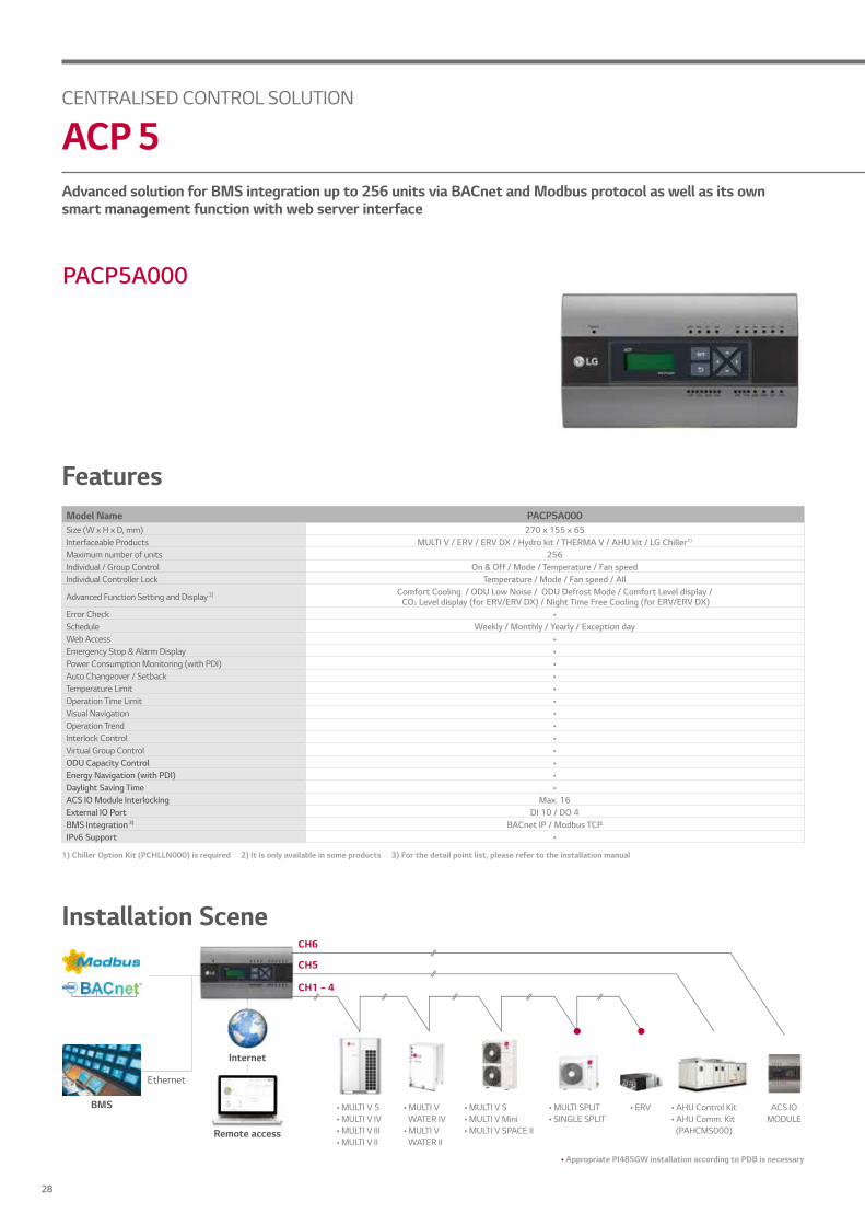
Advanced solution for BMS integration up to 256 units via BACnet and Modbus protocol as well as its own smart management function with web server interface
PACP5A000
FeaturesModel Name PACP5A000Size (W x H x D, mm) 270 x 155 x 65Interfaceable Products MULTI V / ERV / ERV DX / Hydro kit / THERMA V / AHU kit / LG Chiller1)
Maximum number of units 256Individual / Group Control On & Off / Mode / Temperature / Fan speedIndividual Controller Lock Temperature / Mode / Fan speed / All
Advanced Function Setting and Display 2) Comfort Cooling / ODU Low Noise / ODU Defrost Mode / Comfort Level display / CO2 Level display (for ERV/ERV DX) / Night Time Free Cooling (for ERV/ERV DX)
Error Check •Schedule Weekly / Monthly / Yearly / Exception dayWeb Access •Emergency Stop & Alarm Display •Power Consumption Monitoring (with PDI) •Auto Changeover / Setback •Temperature Limit •Operation Time Limit •Visual Navigation •Operation Trend •Interlock Control •Virtual Group Control •ODU Capacity Control •Energy Navigation (with PDI) •Daylight Saving Time •ACS IO Module Interlocking Max. 16External IO Port DI 10 / DO 4BMS Integration 3) BACnet IP / Modbus TCPIPv6 Support •
Installation Scene
1) Chiller Option Kit (PCHLLN000) is required 2) It is only available in some products 3) For the detail point list, please refer to the installation manual
Internet
Remote access
• AHU Control Kit• AHU Comm. Kit
(PAHCMS000)
• MULTI V 5• MULTI V IV• MULTI V III• MULTI V II
• MULTI V S• MULTI V Mini• MULTI V SPACE II
• MULTI VWATER IV
• MULTI VWATER II
• ERV• MULTI SPLIT• SINGLE SPLIT
CH1 ~ 4
CH5
CH6
• Appropriate PI485GW installation according to PDB is necessary
ACS IO MODULE
Ethernet
BMS
CENTRALISED CONTROL SOLUTION
ACP 5
28

CON
TROL
SOLU
TION
FeaturesModel Name PACM5A000*Size (W x H x D, mm) 270 x 155 x 65
Interfaceable Products MULTI V / ERV / ERV DX / Hydro kit / THERMA V / AHU kit / LG Chiller1)
Maximum number of units 8,192 (supports 32 ACP IV/5 or AC Smart IV/5)**
Individual / Group Control On & Off / Mode / Temperature / Fan speed
Individual Controller Lock Temperature / Mode / Fan speed / All
Error Check •
Schedule Weekly / Monthly / Yearly / Exception day
Web Access •
Emergency Alarm Display •
Power Consumption Monitoring (with PDI) •
Auto Changeover / Setback •
Temperature Limit •
Operation Time Limit •
Visual Navigation •
Operation Trend •
Interlock Control •
Virtual Group Control •
ODU Capacity Control •
Energy Navigation (with PDI) •
ACS IO Module Interlocking •
PACM5A000
Multiple ACP and AC Smart integration solution to manage multi sites up to 8,192 units as a single system
AC Manager
5
AC Manager
5
ScheduleFunction
EnergyManagement
OperationTrending Report
AutomaticE-mail Sending
*AC Manager 5 requires ACP IV/5 or AC Smart IV/51) Chiller Option Kit (PCHLLN000) is required
CENTRALISED CONTROL SOLUTION
AC MANAGER 5
29LG Multi V 5 Air Conditioners - Control Solution & Accessories

Control Kit Comm. KitExternal Device
• Appropriate PI 485 should be used according to PDB
Solution Overview
AC Ez Touch
ACS IO Module
PDI
Comm. Kit
Light Pump
Fan Etc
Dry Contact
BMS System
PACM5A000
PACS5A000
PACP5A000
CENTRALISED CONTROL SOLUTION
AC MANAGER 5
30
CON
TROL
SOLU
TION
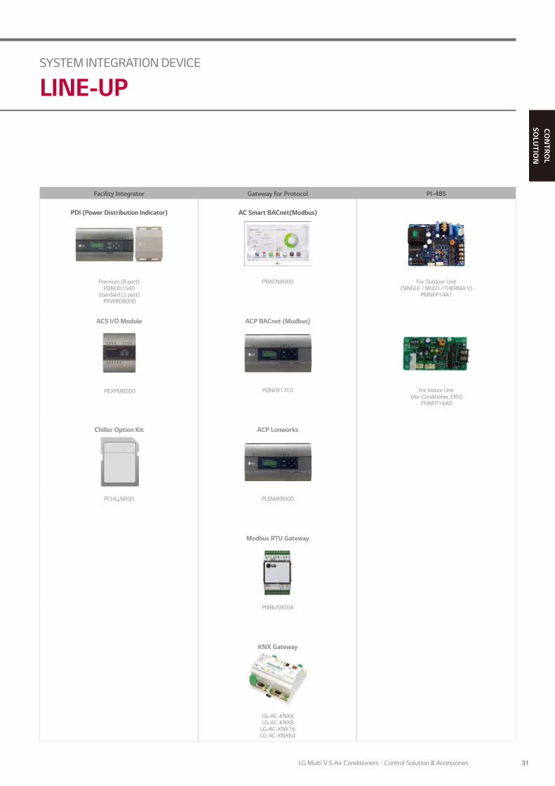
Facility Integrator Gateway for Protocol PI-485
PDI (Power Distribution Indicator) AC Smart BACnet(Modbus)
Premium (8 port)PQNUD1S40
Standard (2 port) PPWRDB000
PBACNA000 For Outdoor Unit(SINGLE / MULTI / THERMA V)
PMNFP14A1
ACS I/O Module ACP BACnet (Modbus)
PEXPMB000 PQNFB17C0 For Indoor Unit (Air-Conditioner, ERV)
PHNFP14A0
Chiller Option Kit ACP Lonworks
PCHLLN000 PLNWKB000
Modbus RTU Gateway
PMBUSB00A
KNX Gateway
LG-AC-KNX4LG-AC-KNX8
LG-AC-KNX16LG-AC-KNX64
SYSTEM INTEGRATION DEVICE
LINE-UP
31LG Multi V 5 Air Conditioners - Control Solution & Accessories

Pulse Signal Power In 3 phase 4 wire50Hz / 60Hz, 380V
RS485 (LGAP)
Watt Meter
Central Controller
PDI
Power Cable for 3 Phase 4 Wire
Communication Cable (2 Wire Shielded Cable)
Pulse Signal Wire
* Power cable and type could be different from this scene depending on the Outdoor unit’s specification* Measured power consumption could be different between PDI and Watt meter* Applicable Central Controller : ACP series (IV/5/BACnet/Lonworks), AC Smart series(IV/5/BACnet), AC Ez Touch
Combination : we recommend you to connect separated watt meter for Outdoor units to have correct power distribution value
PDI shows distributed power consumption of up to 128 indoor units
PremiumPQNUD1S40 (8 port)
StandardPPWRDB000 (2 port)
Features
Installation Scene
Model Name PQNUD1S40 PPWRDB000Size (W x H x D, mm) 270 x 155 x 65
Interfaceable Products Air conditioner, ERV DX
Maximum Number of Power Meters 8 2
Maximum Number of Units 128
Data Backup When Power Outage •
Power Input PDI : AC 24V, Transformer : AC 220-240V
SYSTEM INTEGRATION DEVICE
PDI (POWER DISTRIBUTION INDICATOR)
32

CON
TROL
SOLU
TION
Model Name Min. Max.
Analog Input
NTC 10k 0.68k Ω 177k Ω
PT 1000 803 Ω 1,573 Ω
Ni 1000 871.7 Ω 1,675.2 Ω
DC (Voltage) 0V 10V
DC (Current) 0mA 20mA
Analog Output - 0V 10V
Digital InputBinary Input(Non Voltage) - -
Digital Output Normal open - 30VAC / 30VDC, 2APACS4B000 PACP4B000 PACM5A000Number of Indoor Units 64 ~ 128 128 ~ 256 8,192
Max. I/O Points 130 238 1,260
Maximum Number of Node 9 16 -
* Maximum number of Indoor units may be reduced by increasing the number of I/O points.1) The type of UI (Universal Input) is selectable among Digital Input and Analog Input
Model Name PEXPMB000
Linkable Products
PACS4B000PACS5A000PACP4B000PACP5A000
Communication RS-485 1
I/O
Digital Input 3
Digital Output 3
Universal Input 1) 4
Analog Output 4
AC Smart IV/5 ACP IV/5or
PACM5A000 • Sensor / Valve / Actuator • Pump / Fan etc.
Fan AlarmLightingPUMP DDC
* D I : Digital Input, DO : Digital Output, UI : Universal Input, AO : Analog Output / Please contact our regional office to have connectable relay specification for analog output* The type of UI (Universal Input) is selectable among Digital Input and Analog Input
This module can be connected with ACP IV/5 or AC Smart IV/5 controller if additional I/O points such as DI/DO and AI/AO for 3rd party devices control and monitoring are needed.
PEXPMB000
Features
Installation Scene
SYSTEM INTEGRATION DEVICE
ACS I/O MODULE
33LG Multi V 5 Air Conditioners - Control Solution & Accessories

PBACNA000
* In case of using Modbus, the compatibility is different from BACnet. Refer to manual in detail.
Controlling Monitoring ItemsOn / Off Command On / Off Status
Operation Mode Setting Operation Mode Status
Fan Speed Setting Fan Speed Status
Lock Setting Lock Status
Air Flow Setting Air Flow Setting
Set Temperature Setting Set Temperature Status
- Current Space Temperature Status
- Error Status
User Mode Setting (for only ERV) User Mode Status (for only ERV)
- Accumulator Power Distribution Status
Upper Limit Temp. Setting Upper Limit Temperature Status
Low Limit Temp. Setting Low Limit Temperature Status
Mode Lock Setting Mode Lock StatusAC Operation Mode Setting
(ERV DX only)Air Conditioner Operation
Mode Status (ERV DX only)AC On / Off Command
(ERV DX only)Air Conditioner On / Off Status
(ERV DX only)
Features
Installation Scene
1) Assignment of public IP address is required to access central controller through internet.*AC Smart BACnet will be discontinued and replaced by AC Smart 5
• Appropriate PI 485 should be used according to PDB
Indoor unit : Max. 128 units (Air conditioner & Ventilation) / Indoor address : 00 ~ 7F
BMS system
Internet
Lighting control Utility controlRemote checking
CH2
CH1
1)
Backup operation
• AHU (Control Kit)• MULTI V 5• MULTI V IV• MULTI V III• MULTI V II
• MULTI V S• MULTI V Mini• MULTI V
SPACE II
• MULTI VWATER IV
• MULTI VWATER II
• ERV / ERV DX
• MULTI SPLIT• SINGLE SPLIT
• Process Ability- EHP Type : 128 units (Indoor / ERV / ERV DX / Hydro Kit / THERMA V)- AHU Control kit : Maximum 16 units
• Self installation verification function on touchscreen or using Internet (Web Server Included)- Setting gateway- Diagnosis of communication status on LG Air-conditioner network
• Modbus TCP Protocol Support• BTL Certified (B-ASC)• It offers a variety of functions as ACP which allows
the customer to efficiently control various types of equipment from the customer’s own Integration.
SYSTEM INTEGRATION DEVICE
AC SMART BACNET
34

CON
TROL
SOLU
TION
PQNFB17C0
* In case of using Modbus, the compatibility is different from BACnet. Refer to manual in detail.
Controlling Monitoring ItemsOn / Off Command On / Off Status
Operation Mode Setting Operation Mode Status
Fan Speed Setting Fan Speed Status
Lock Setting Lock Status
Air Flow Setting Air Flow Setting
Set Temperature Setting Set Temperature Status
- Current Space Temperature Status
- Error Status
User Mode Setting (for only ERV) User Mode Status (for only ERV)
- Accumulator Power Distribution Status
Upper Limit Temp. Setting Upper Limit Temperature Status
Low Limit Temp. Setting Low Limit Temperature Status
Mode Lock Setting Mode Lock StatusAC Operation Mode Setting
(ERV DX only)Air Conditioner Operation
Mode Status (ERV DX only)AC On / Off Command
(ERV DX only)Air Conditioner On / Off Status
(ERV DX only)
Features
* Please refer PDRYCB500 for Modbus RTU
• Process Ability- EHP Type : 256 units (Indoor / ERV / ERV DX / Hydro Kit / THERMA V)- AHU Control kit : Maximum 16 units
• Self installation verification function using internet (Web Server Included)- Setting gateway- Diagnosis of communication status on LG Air-conditioner network
• Modbus TCP Protocol Support• BTL Certified (B-ASC)• It offers a variety of functions as ACP which allows
the customer to efficiently control various types of equipment from the customer’s own Integration.
Installation Scene
1) Assignment of public IP address is required to access central controller through internet.*ACP BACnet will be discontinued and replaced by ACP 5
Appropriate PI 485 should be used according to PDB
Indoor unit : Max. 256 units (Air conditioner & Ventilation) / Indoor address : 00 ~ FF
BMS system
Internet
Lighting control Utility controlRemote checking
CH1 ~ 4
CH5
1)
Backup operation
• AHU (Control Kit)• MULTI V 5• MULTI V IV• MULTI V III• MULTI V II
• MULTI V S• MULTI V Mini• MULTI V
SPACE II
• MULTI VWATER IV
• MULTI VWATER II
• ERV / ERV DX
• MULTI SPLIT• SINGLE SPLIT
PACS4B000
SYSTEM INTEGRATION DEVICE
ACP BACNET GATEWAY
35LG Multi V 5 Air Conditioners - Control Solution & Accessories

Internet
PACS4B000
1)
Backup operation
Indoor unit : Max. 64 units (Air conditioner & Ventilation) / Indoor address : 00 ~ FFCH1 ~ 4
CH5
• AHU (Control Kit)• MULTI V 5• MULTI V IV• MULTI V III• MULTI V II
• MULTI V S• MULTI V Mini• MULTI V SPACE II
• MULTI V WATER IV
• MULTI V WATER II
• ERV• MULTI SPLIT• SINGLE SPLIT
BMS systemLighting control Utility controlRemote checking
PLNWKB000
Controlling Monitoring ItemsOn / Off Command On / Off Status
Operation Mode Setting Operation Mode Status
Fan Speed Setting Fan Speed Status
Lock Setting Lock Status
Air Flow Setting Air Flow Setting
Set Temperature Setting Set Temperature Status
- Current Space Temperature Status
- Error Status
- Accumulator Power Distribution Status
Upper Limit Temperature Setting Accumulator Power Distribution Status
Low Limit Temperature Setting Low Limit Temperature Setting
Mode Lock Setting Mode Lock Status
Peak Operation Ratio Setting Peak Operation Ratio Setting
All On / Off Setting -
- Total Accumulate Power Status
Features
Installation Scene
1) Assignment of public IP address is required to access central controller through internet. • Appropriate PI 485 should be used according to PDB
• Process Ability- EHP Type : 64 units (Indoor / ERV / Hydro Kit / THERMA V)- AHU Control kit : Maximum 16 units
• Connect to use Lonworks® protocol and LG air conditioner protocol.
• Self installation verification function using internet (Web Server Included)- Setting gateway- Diagnosis of communication status on LG Air-conditioner network
• It offers a variety of functions as ACP which allows the customer to efficiently control various types of equipment from the customer’s own Integration.
SYSTEM INTEGRATION DEVICE
ACP LONWORKS GATEWAY
36

CON
TROL
SOLU
TION
BMS BMS
Installation Scene
Providing Modbus RTU connection between LG Air conditioners and BMS
PMBUSB00A
Features
• Function- MODBUS RTU communication with MODBUS master controller - MODBUS RTU slave (RS485) / 9,600 bps- Applicable for MULTI V - Size (W*H*D) : 53.6 x 89.7 x 60.7- Max. 16 IDUs with single module / Max. 64 IDUs with 4 modules - Power : DC 12V
• Modbus Memory Map*
• Single moduleMax. 16 indoor units with a single module
• Multiple moduleMax. 64 indoor units with 4 modules in one Modbus communication line
Register Read Write Description Notes 00001 • • Operation 0 : Off / 1 : On
00002 • • Total Lock 0 : Unlock / 1 : Lock
00005 • • Auto Swing 0 : Manual / 1 : Auto
00006 • • Operation Mode Lock 0 : Unlock / 1 : Lock
00007 • • Fan Speed Lock 0 : Unlock / 1 : Lock
00008 • • Set Temperature Lock 0 : Unlock / 1 : Lock
10001 • - Error Alarm 0 : Normal / 1 : Error
10002 • - Thermo On / Off 0 : Thermo Off / 1 : Thermo On
30001 • - Error Code 0 ~ 255
30002 • - Pipe In Temperature Degrees C x 10
30003 • - Pipe Out Temperature Degrees C x 10
30004 • - Room Temperature Degrees C x 10
40001 • • Operation Mode 0 : Cooling / 1 : Dry / 2 : Fan / 3 : Auto / 4 : Heating
40002 • • Set Temperature Degrees C x 10
40003 • • Fan Speed 1 : Low / 2 : Medium / 3 : High / 4 : Auto
Modbus RTU
RS485(LGAP) RS485(LGAP)
Max. 16 outdoor units in one RS485(LGAP) line
Modbus RTU
SYSTEM INTEGRATION DEVICE
MODBUS RTU GATEWAY
37LG Multi V 5 Air Conditioners - Control Solution & Accessories

Specially designed to allow monitoring and bidirectional control of all the parameters and functionality of LG air conditioners from KNX installations
LG-AC-KNX4 / LG-AC-KNX8LG-AC-KNX16 / LG-AC-KNX64
Easy to use tool for the configuration of intesisBox, in a fast and effective way.It offers the maximum integration possibilities with a minimal knowledge required on the system to be integrated.
Link BoxEIB Configuration Software for IntesisBox® KNX serious
- Only needed during configuration.- One single tool for the configuration of the whole range of IntesisBox KNX series gateways.- Supplied with IntesisBox with no additional cost.- Configuration examples for all systems that can be integrated.- Mapping table editable using excel, allowing a simple and fast association of KNX Group
Addresses, exported from ETS, to IntesisBox’s datapoints.- Includes powerful and useful features for configuration, setup and troubleshooting.
LinkBoxEIBConfiguration software
- Easy installation, direct connection to all outdoor units (communication interface PMNFP14A1, when needed) and Heat recovering units (communication interface PHNFP14A0, when needed) throungh the RS485 Bus.
- Great integration flexibility. Using the supplied software LinkBoxEIB, a complete set of communication objects can be accessed.- Direct connection to KNX bus- Independent management of communications- Power supply : 9 to 24V DC or 24V AC- Standard DIN-Rail 6 modules enclosure- Maximum connection unit- LG Slave Central controller (for example, AC Smart) and PDI can be operated with KNX gateway.
Features
Model Name Max. Connection UnitsLG-AC-KNX4 4
LG-AC-KNX8 8
LG-AC-KNX16 16
LG-AC-KNX64 64
Installation Scene
(Only Neededfor Configuration)
ConfigurationSoftware
LinkBoxEIB(above 1.1.22)
RS232 RS485
IntesisBoxLG-AC-KNX4LG-AC-KNX8
LG-AC-KNX16LG-AC-KNX64
EIB Bus
• PDI• AC Smart IV • MULTI V 5• MULTI V IV• MULTI V III• MULTI V II
• MULTI V S• MULTI V Mini• MULTI V
SPACE II
• MULTI V WATER IV
• MULTI V WATER II
• ERV• MULTI SPLIT• SINGLE SPLIT
• Appropriate PI 485 should be used according to PDB 1) This product is provided by INTESIS.
SYSTEM INTEGRATION DEVICE
KNX GATEWAY 1)
38

CON
TROL
SOLU
TION
• Model Name : PHNFP14A0• Power : Connected with the Indoor Units• 1 for Each Indoor Unit - Indoor Unit (Air-Conditioner, ERV)
PI 485 converts LG air conditioner’s protocol to the RS485 protocol for the central controller
PMMFP14A1 / PHNFP14A0
• Model Name : PMNFP14A1• Power : Single Phase AC 220-240V 50/60Hz• 1 for Each Outdoor Unit - MULTI V MINI (ARUN40GS2A / ARUV40GS2A Only needs PI485) - SINGLE SPILIT - MULTI SPLIT - THERMA V
Features
* MULTI V PLUS II & MULTI V III & MULTI V IV series do not require any other PI 485 since these series have PI 485 in its outdoor unit PCB.
SYSTEM INTEGRATION DEVICE
PI 485
39LG Multi V 5 Air Conditioners - Control Solution & Accessories

40
OTHER INTEGRATION CONTROL SOLUTION

CON
TROL
SOLU
TION
Indoor UnitOutdoor Unit AHU Kit
Dry Contact Control Accessory
Simple Dry Contact Group Control Wire IO Module (Input / Output Module) Communication Kit
PDRYCB000 PZCWRCG3 PVDSMN000 PAHCMR000
2 Points Dry Contact Remote Temperature Sensor Dry Contact for Demand Control
PDRYCB400 PQRSTA0 PQDSBCDVM0 PAHCMS000
Dry Contact for Thermostat Zone Controller Variable Water Flow Control Kit Control Kit
PDRYCB300 ABZCA PWFCKN000 PRCKD21EPRCKD41E
For Modbus EEV Kit (Electronic Expansion Valve)
PDRYCB500 PRVCO PRLK048A0 / PRLK096A0
Low Ambient Kit TXV Kit (Thermal Expansion Valve)
PRVC2 PATX13A0E / PATX20A0EPATX25A0E / PATX35A0E
PATX50A0E
Cool / Heat Selector
PRDSBM
OTHER INTEGRATION CONTROL SOLUTION
LINE-UP
41LG Multi V 5 Air Conditioners - Control Solution & Accessories

PDRYCB000
Installation Scene
FeaturesModel Name PDRYCB000Contact Point 1 Contact Point
Contact Voltage Rating AC 220-240V
On / Off Control •
Error Alarm Output •
Operation On / Off Output •
Rotary Switch 1 (Set Temperature selection) -
Rotary Switch 2 (Operation Logic selection) -
Size (W x H, mm) 120 x 120
* Refer to each models PDB for applicable models. * Maximum operation AC : 3A* 4th generation indoor unit has 1 contact point function for On / Off control. But in case of using more function of Dry Contact besides On / Off control, Dry Contact is needed.
Connection between an indoor unit and external devices to control various functions
System Structure
CN - CC
Key Switch Lighting Sensor
Fire Alarm Timer MotionDetect Sensor
Door CheckSensor
Dry contact(Contact point linked
with outer part)
Signal Point
Contact Point Input
Operation On/Off Status
Error AlarmCN - CC
Indoor UnitPCB
OTHER INTEGRATION CONTROL SOLUTION
DRY CONTACT
42

CON
TROL
SOLU
TION
PDRYCB400
FeaturesModel Name PDRYCB400Contact Point 2 Contact Point
Contact Voltage Rating DC 5 ~ 12V / Non Voltage
On / Off Control •
Error Alarm Output •
Operation On / Off Output •
Rotary Switch 1 (Set Temperature selection) •
Rotary Switch 2 (Operation Logic selection) •
Size (W x H, mm) 120 x 120
* Refer to each models PDB for applicable models. * Maximum operation AC : 3A* 4th generation indoor unit has 1 contact point function for On / Off control. But in case of using more function of Dry Contact besides On / Off control, Dry Contact is needed.
Signal Point
Error Alarm
Contact Point Input 1
Contact Point Input 2
Operation On/Off Status
CN - CC
Indoor UnitPCB
Installation Scene2 inputs interworking Refrigerant leakage detection alarm
Leakage Alarm
Card key
Window Sensor
Card key Leakage DetectorCard keyCard key
CN - CC CN - CC
43LG Multi V 5 Air Conditioners - Control Solution & Accessories

Connection between an indoor unit and external devices to control various functions
CN - CC
Control Module
PDRYCB300
Installation Scene
FeaturesModel Name PDRYCB300Contact Voltage Rating DC 5 ~ 12V / Non Voltage
On / Off Control •
Mode Control •
Fan Speed Setting •
Thermo Off •
Error Alarm Output •
Operation On / Off Output •
Rotary Switch 1 (Set Temperature Selection) •
Rotary Switch 2 (Operation Logic Selection) •
Size (W x H, mm) 120 x 120
* Please contact our regional office to have full compatible room controller list
Signal Point
CN - CC
Indoor UnitPCB
Operation On/OffThermo On/OffOperation Mode (Fan/Heat/Cool)Fan Speed (Low/Middle/High)Operation On/Off StatusError Alarm
OTHER INTEGRATION CONTROL SOLUTION
DRY CONTACT
44
CON
TROL
SOLU
TION
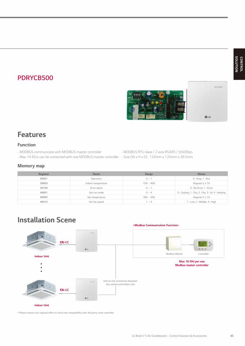
PDRYCB500
Installation Scene
Features
Register Name Range Notes00001 Operation 0 ··· 1 0 : Stop, 1 : Run
30003 Indoor temperature 100 ··· 400 Degrees C x 10
30100 Error alarm 0 ··· 1 0 : No Error, 1 : Error
40001 Set run mode 0 ··· 4 0 : Cooling, 1 : Dry, 2 : Fan, 3 : AI, 4 : Heating
40002 Set temperature 180 ··· 300 Degrees C x 10
40015 Set fan speed 1 ··· 3 1 : Low, 2 : Middle, 3 : High
* Please contact out regional office to check the compatibility with 3rd party room controller
CN-CC
CN-CC
<Modbus Communication Function>
Indoor Unit
One to one connection between dry contact and indoor unit
Indoor Unit
ControllerModbus Master
CN-CC
CN-CC
Max. 16 IDU per one Modbus master controller
. . .
Function- MODBUS communicate with MODBUS master controller - MODBUS RTU slave / 2 wire RS485 / 9,600bps- Max. 16 IDUs can be connected with one MODBUS master controller - Size (W x H x D) : 120mm x 120mm x 36.5mm
Memory map
45LG Multi V 5 Air Conditioners - Control Solution & Accessories
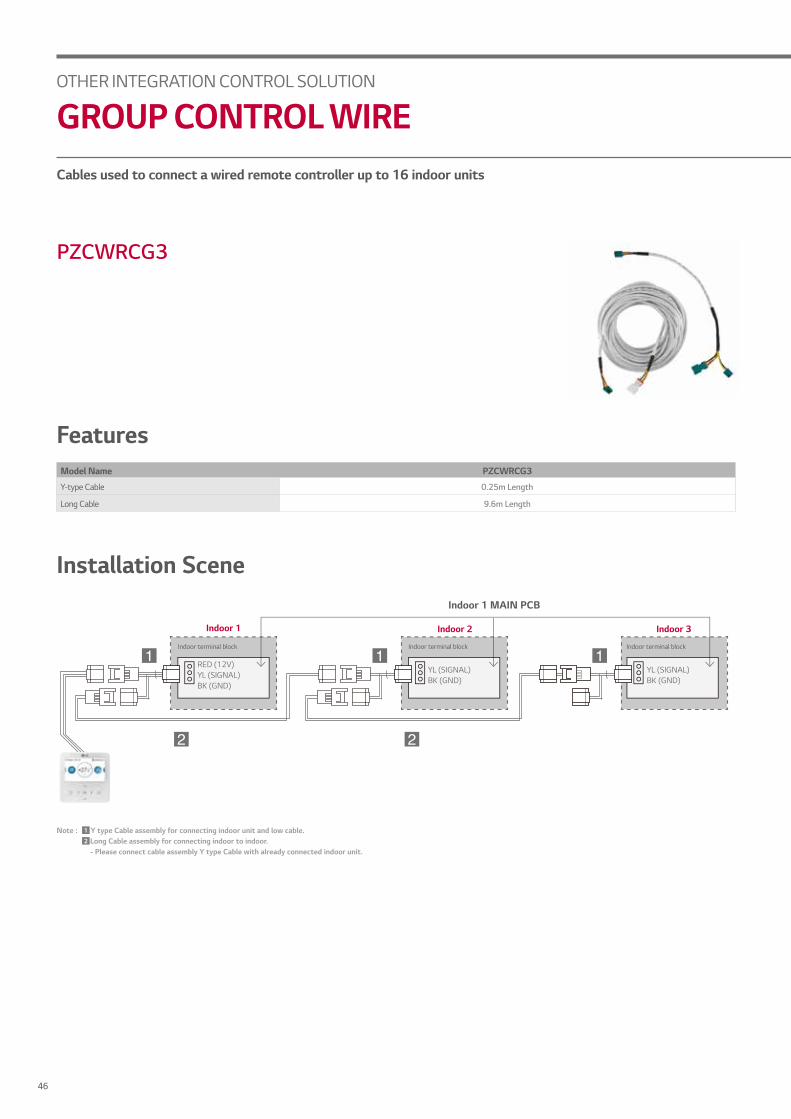
Cables used to connect a wired remote controller up to 16 indoor units
PZCWRCG3
FeaturesModel Name PZCWRCG3
Y-type Cable 0.25m Length
Long Cable 9.6m Length
Installation Scene
Indoor 1
Indoor 1 MAIN PCB
Indoor terminal block
RED (12V)YL (SIGNAL)BK (GND)
YL (SIGNAL)BK (GND)
YL (SIGNAL)BK (GND)
Indoor terminal block Indoor terminal block
Note : Y type Cable assembly for connecting indoor unit and low cable. Long Cable assembly for connecting indoor to indoor. - Please connect cable assembly Y type Cable with already connected indoor unit.
1
2
Indoor 2 Indoor 3
OTHER INTEGRATION CONTROL SOLUTION
GROUP CONTROL WIRE
46

CON
TROL
SOLU
TION
Sensor for detecting the room temperature
PQRSTA0
Features• It detects the exact room temperature instead of indoor unit’s air temperature sensor• Applied to Ceiling Mounted Cassette, Ceiling Concealed Duct, THERMA V and Hydro Kit• Extension cable (15m) is included
Installation Scene1. Wire to the control box in the indoor unit by removing the existing thermistor and connect the extension cable its place.2. Cut the extension cable to the appropriate length and connect the screw terminal of the remote sensor.
Indoor Unit
Remote Temperature Sensor
Wired RemoteController
Extension Cable
CN-ROOM
OTHER INTEGRATION CONTROL SOLUTION
REMOTE TEMPERATURE SENSOR
47LG Multi V 5 Air Conditioners - Control Solution & Accessories

Controls air conditioning in up to 4 zones by external thermostat
ABZCA
Zone Controlsub PCB
Indoor Unit(Duct Type)
ROOM1 ROOM2
ROOM3 ROOM4
Thermostat Temperature sensor
Temperature sensor Temperature sensor
Ceiling Concealed Duct
AC 24V
Zone controller
1
2
3
4
5
6
7
8
ROOM(External)THERMOSTAT #1
DamperOr Relay
ROOMTHERMOSTAT #2
DamperOr Relay
ROOMTHERMOSTAT #3
DamperOr Relay
ROOMTHERMOSTAT #4
DamperOr Relay
CN - ZONE
Features• Controls different zones (up to 4 zones) by external thermostat (AC a24V)
• Maintain proper air volume of each zone• Auto variation of dampers• Auto control of fan speed and On / Off operation
Models Applied• Ceiling Concealed Duct (refer to PDB for applicable models)
Wiring Diagram
OTHER INTEGRATION CONTROL SOLUTION
ZONE CONTROLLER
48

CON
TROL
SOLU
TION
Interface module between system air conditioner’s outdoor unit and external device
PVDSMN000
FeaturesFunction- Demand control - Low noise operation- Output outdoor or indoor unit operation status - Output error status
Description- IO Module is communication interface module for connection between MULTI V 5 and external IO (Input / Output Module) devices.
Part Description1) Digital Input Part (DI : Dry Contact Input)
• Demand control by contact input (3 Step)• Low Noise Operation input• Priority Setting input :
Setting the priority of demand control command (Capacity control for external signal from DDC vs Peak controlby LG Central controller)- Open : External signal has priority to central controller (Default) - Close : Central controller has priority to external signal
2) Analog Input Part (AI : DC 0 ~ 10V)• Demand control by analog input (10 Step)
3) Digital Output Part (DO : 250VAC, Max 1A)• Error status relay output• Operation status relay output • Valve control
Note : IO Module is not compatible for MULTI V III
Models Applied• MULTI V 5 • MULTI V IV• MULTI V WATER IV • MULTI V S
OTHER INTEGRATION CONTROL SOLUTION
IO MODULE
49LG Multi V 5 Air Conditioners - Control Solution & Accessories

Installation SceneDemand ControlProvides variable setting for demand control according to input method to reduce power consumption. This function supports 2 types of input signal : AI (0 ~ 10V, 10 Step) and contact signal (3 Step).
Range of Operation RateAI 0 ~ 10V : 0%, 40% ~ 100%
Contact signal (3 steps) : 0%, 40% ~ 80%
MULTI V 5
or
IO Module
Capacity Control with
Contact Signal (3 Points / 3 Steps)
DDC(Direct Digital Controller)
MULTI V WATER IV
Noise Level
Max 7 dB*
(dB)
MULTI V 5 IO Module
Contact Signal
DDC(Direct Digital Controller) Timer
or
* 8 HP model, Sound power level can be changed by outdoor unit operation status and low noise operation input signal.
Low Noise OperationTo reduce noise level , control outdoor unit’s fan speed by dry contact input.
MULTI V 5 IO Module
Refrigerant Leakage detection with Pump-downFor safety, IO module close refrigerant valve with Pump-down
2. Valve CloseLiquid Pipe
Gas Pipe
Gas Sensor
Gas Sensor
Alarm
Refrigerant
1. Sense the Gas3. Operation Stop
OTHER INTEGRATION CONTROL SOLUTION
IO MODULE
50

CON
TROL
SOLU
TION
Accessory developed for controlling the water flow
PWFCKN000 (MULTI V WATER IV)PRVC0 (MULTI V WATER II)
From Water Source
Flow control
valve
Flow control
valve Pressuresensor
Cooling T
ower
Inverter Pum
pV
ariable Water Flow
Control V
alve
Cooling T
ower
Inverter Pum
pV
ariable Water Flow
Control V
alve
Inverter pump
0 ~ 10V (Analog output)
Pump / Cooling Tower Controller
Cooling Tower
Inverter Pump Variable Water Flow Control Valve
Single Line
Water Flow Line
FeaturesFunction- Water pump or valve control (0 ~ 10V)- Minimum output voltage setting available- Operation, error output (250VAC, Max 1A)- Dry contact input and analog output for demand control- Digital output for operation, error status (250VAC, Max 1A)
Advantage- Water flow consumption reduction- Pump electricity consumption reduction- Including IO Module (Dry contact input, Analog input / output, Digital output)
: Using Dry contact and variable water flow control function simultaneously
Wiring Diagram
• Flow control valve : Regulates the flow or pressure of a fluid, normally responding to signals generated by independent devices.• Flow Meter : Measures mass flow rate of a fluid traveling through a tube. (The mass flow rate is the mass of the fluid traveling past a fixed point per unit time.)• Pressure Sensor : Measures the pressure.
OTHER INTEGRATION CONTROL SOLUTION
VARIABLE WATER FLOW CONTROL KIT
51LG Multi V 5 Air Conditioners - Control Solution & Accessories
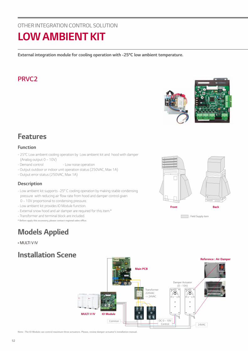
External integration module for cooling operation with -25°C low ambient temperature.
PRVC2
Front
: Field Supply item
Back
Note : The IO Module can control maximum three actuators. Please, review damper actuator’s installation manual.
Function- 25°C Low ambient cooling operation by Low ambient kit and hood with damper
(Analog output 0 ~ 10V)- Demand control - Low noise operation- Output outdoor or indoor unit operation status (250VAC, Max 1A)- Output error status (250VAC, Max 1A)
Description- Low ambient kit supports -25° C cooling operation by making stable condensing
pressure with reducing air flow rate from hood and damper control given 0 ~ 10V proportional to condensing pressure.
- Low ambient kit provides IO Module function.- External snow hood and air damper are required for this item.*- Transformer and terminal block are included.* Before apply this accessory, please contact regional sales office.
Main PCB
Reference : Air Damper
MULTI V IV IO Module
Transformer220VAC -> 24VAC
Damper Actuator(0 ~ 10V)
DC 0 ~ 10VControl
Common 24VAC
Models Applied• MULTI V IV
Installation Scene
Features
OTHER INTEGRATION CONTROL SOLUTION
LOW AMBIENT KIT
52

CON
TROL
SOLU
TION
Cooling, heating, or fan mode can be selected to prevent cooling and heating mixing errors during seasonal changes
Wiring Diagram
PRDSBM
Features• Indoor unit mode control without central controller• Select operation mode : Cooling, Heating, Fan mode• Mode lock for cooling & heating mixing error-proof during the change of season
* Communication line length can be maximum 300m, use Communication line as thick as 1.25mm
• Connect Terminals (1, 2, GND) on the back side of the outdoor drycontact to terminals (1, 2, GND) of outdoor as show below.
Models Applied• MULTI V 5 • MULTI V IV • MULTI V WATER S • MULTI V WATER II • MULTI V S • MUL TI V PLUS II, MULTI V PLUS • MULTI V SPACE II • MULTI V WATER IV • MULTI V MINI
Fan Mode
Coolingonly
Mode Change
<Outdoor Main PCB >
Push Button
Insert wire method
Push arrow direction
Insert wire to connector
Heatingonly
Shows field wiringConnected wiring
OTHER INTEGRATION CONTROL SOLUTION
COOL / HEAT SELECTOR
53LG Multi V 5 Air Conditioners - Control Solution & Accessories

A solution to connect LG’s high efficiency system to the DX coil of an air handling unit for the maximum energy savings
Specifications
Type Model
Combination
Description
Dimensions (mm)
Outdoor Unit
EEV Kit
TXV Kit
CentralisedController W H D
Communication kit
PAHCMR000 Multi V • • •
Return / room air temperature control by DDC or LG individual / centralised controller 300 300 155
Single Split - - •
PAHCMS000 Multi V • • •
Discharge air temperature control by DDC or LG individual / centralised controller 380 300 155
Single Split - - •
Control kitPRCKD21E Multi V - • • Max capacity 1~4 master outdoor unit 600 750 285
PRCKD41E Multi V - • • Max capacity 5~8 master outdoor unit 600 750 285
Communication & Control Kit
Type Model Capacity Range
Pipe Diameter (mm) Dimensions (mm)
Liquid(ODU)
Liquid(AHU)
Gas(ODU)
Gas(AHU) W H D
EEV Kit(ElectronicExpansion Valve)
PRLK048A0 2.6 ~ 28.0 kW 12.7 12.7 - - 217 404 83
PRLK096A0 33.6 ~ 56.0 kW 12.7 12.7 - - 217 404 83
TXV Kit(ThermalExpansion Valve)
PATX13A0E 22.4 ~ 44.8 kW 15.88 15.88 22.22 22.22 491 238 174
PATX20A0E 50.4 ~ 72.8 kW 15.88 22.22 28.58 28.58 491 238 174
PATX25A0E 78.4 ~ 100.8 kW 22.22 28.58 34.92 34.92 491 238 174
PATX35A0E 106.4 ~ 128.8 kW 28.58 34.92 41.3 41.3 491 238 174
PATX50A0E 134.4 ~ 156.8 kW 28.58 34.92 41.3 41.3 561 291 192
Expansion Valves
PAHCMR000 PAHCMS000 PRCKD21E / PRCKD41E PRLK048A0PRLK096A0
PATX13A0E / PATX20A0EPATX25A0E / PATX35A0EPATX50A0E
COMMUNICATION KIT CONTROL KIT EEV KIT TXV Kit (Thermal Expansion Valve)
OTHER INTEGRATION CONTROL SOLUTION
AHU KITS
54

CON
TROL
SOLU
TION
Communication Kit
HIGH ENERGY EFFICIENCYLG’s DX AHU solutions are capable of performing all indoor air conditioning tasks with success under all operating conditions thanks to their superior performance with high efficiency heat source system.
Solution benefits offer the following advantages:• High energy efficiency inverter system• Large range of expansion valves
: 3.6 ~ 56 kW EEV Kit, 22.4 ~ 156.8 kW TXV Kit• Connected to various heat sources
: MULTI V, MULTI V WATER, MULTI V S, SINGLE SPLIT
DIVERSE OPTIONS FOR CONTROLAHU communication kit can be connected to various control system such as LG individual/central controller and DDC*.It can be directly connected to DDC without separated controller, so DDC can receive product control and monitor information through contact signal or Modbus protocol.
• Direct wiring between DDC and AHU communication kit - Embedded Digital I/O and Analog Input - Modbus RTU protocol supported• LG Individual/Central controller supported - LG controller stand alone or combination with DDC
*DDC : Direct Digital Controller
EXPANDABLE SYSTEM DESIGNLG AHU system can be a suitable solution for various sites due to its application flexibility and wide range of line up with large capacity models. According to the required capacity, a single or multiple module combination is possible thanks to AHU communication kit’s modular design.
• Multiple module combination for large capacity AHU
LG Controller DDC by Contact signal DDC by Modbus
Central Controller
IndividualController
DDC
AI/DI/DO signal
AHU Kit AHU KitAHU Kit
DDC
Main module Comm. module Comm. module Comm. module
AHU MULTI V 5
MULTI V WATER IV MULTI V S SINGLE SPLIT
55LG Multi V 5 Air Conditioners - Control Solution & Accessories

Communication Kit ApplicationSmall Capacity with Single Split + Return / Room Air Temperature Control
Small Capacity with Single Split + Discharge Air Temperature Control
Note1) PI485(PMNFP14A1) is required for centralised controller2) In case of applying DDC with contact signal, discharge air temperature should be measured and controlled by DDC3) For more detail, please refer to the PDB
TE = Evaporator Temperature (Liquid Pipe / Gas Pipe)
TR = Return Air TemperatureTROOM = Room Air Temperature
Temp. SensorsComm. LineCentral Comm. Line to ODURef. Pipe
Control Option
TROOM
ROOM
TE
TR
AHU DX Coil
OR / AND
Centralised Controller1)SINGLE SPLIT
PAHCMR000 DDC(Modbus or Contact signal)
TE = Evaporator Temperature (Liquid Pipe / Gas Pipe)
TD = Discharge Air TemperatureTROOM = Room Air Temperature
Temp. SensorsComm. LineCentral Comm. Line to ODURef. Pipe
Control Option
TROOM
ROOM
TE
TD
AHU DX Coil
OR / AND
Centralised Controller 1)SINGLE SPLIT
PAHCMS000 DDC(Modbus or Contact signal 2))
OTHER INTEGRATION CONTROL SOLUTION
AHU KITS
56

CON
TROL
SOLU
TION
Communication Kit ApplicationSmall-Medium Capacity with MULTI V + EEV Kit + IDU + Return / Room Air Temperature Control
Small-Medium Capacity with MULTI V + EEV Kit + Discharge Air Temperature Control
Note1) Multiple EEV kits can be applicable with multiple DX Coils and PAHCMR000s2) In case of applying DDC with contact signal, discharge air temperature should be measured and controlled by DDC 3) For more detail, please refer to the PDB
TE = Evaporator Temperature (Liquid Pipe / Gas Pipe)
TR = Return Air TemperatureTROOM = Room Air Temperature
Temp. SensorsComm. LineCentral Comm. Line to ODURef. Pipe
TE = Evaporator Temperature (Liquid Pipe / Gas Pipe)
TD = Discharge Air TemperatureTROOM = Room Air Temperature
Temp. SensorsComm. LineCentral Comm. Line to ODURef. PipeComm. Line between modules
Control Option
TROOM
ROOM
TE2
TE1
TD
AHU DX Coil
OR / AND
Centralised Controller
PAHCMS000
PAHCMR000
DDC(Modbus or Contact signal 2))
Control Option
TROOM
ROOM
TE
TR
AHU DX Coil
OR / AND
Centralised Controller MULTI V
PAHCMR000 DDC(Modbus or Contact signal)
MULTI V
IDUs
EEV Kit 1)
57LG Multi V 5 Air Conditioners - Control Solution & Accessories

Communication Kit ApplicationLarge Capacity with MULTI V + TXV Kit + Return / Room Air Temperature Control
Large Capacity with MULTI V + TXV Kit + Discharge Air Temperature Control
Note1) TXV Kit should be connected with outdoor unit 1:12) In case of applying DDC with contact signal, discharge air temperature should be measured and controlled by DDC3) For more detail, please refer to the PDB
TE = Evaporator Temperature (Liquid Pipe / Gas Pipe)
TR = Return Air TemperatureTROOM = Room Air Temperature
Temp. SensorsComm. LineCentral Comm. Line to ODURef. Pipe
TE = Evaporator Temperature (Liquid Pipe / Gas Pipe)
TD = Discharge Air TemperatureTROOM = Room Air Temperature
Temp. SensorsComm. LineCentral Comm. Line to ODURef. Pipe
Control Option
TROOM
ROOM
TE
TR
AHU DX Coil
OR / AND
Centralised ControllerMULTI V
TXV Kit 1)
PAHCMR000 DDC(Modbus or Contact signal)
T
Control Option
TROOM
ROOM
TE
TD
AHU DX Coil
OR / AND
Centralised ControllerMULTI V
PAHCMS000 DDC(Modbus or Contact signal) 2)
T
OTHER INTEGRATION CONTROL SOLUTION
AHU KITS
58
CON
TROL
SOLU
TION
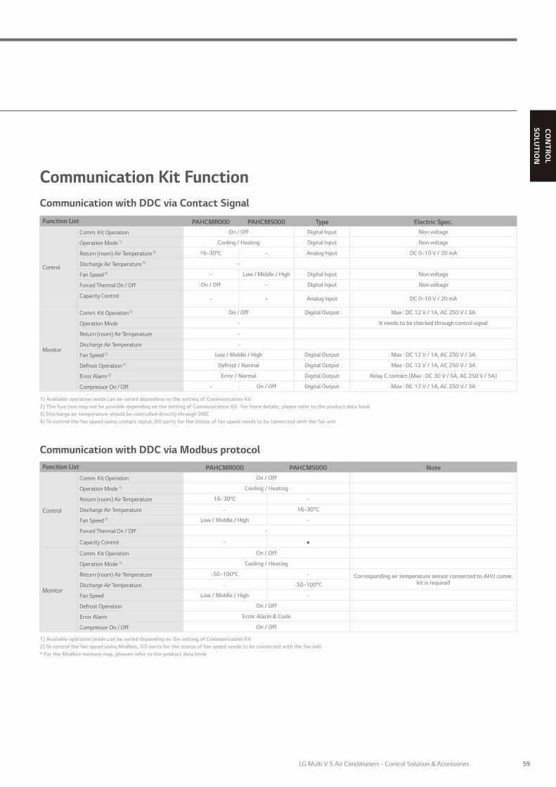
1) Available operation mode can be varied depending on the setting of Communication Kit2) This function may not be possible depending on the setting of Communication Kit. For more details, please refer to the product data book3) Discharge air temperature should be controlled directly through DDC4) To control the fan speed using contact signal, DO ports for the status of fan speed needs to be connected with the fan unit
1) Available operation mode can be varied depending on the setting of Communication Kit2) To control the fan speed using Modbus, DO ports for the status of fan speed needs to be connected with the fan unit* For the Modbus memory map, pleases refer to the product data book
Communication Kit FunctionCommunication with DDC via Contact Signal
Communication with DDC via Modbus protocol
Function List PAHCMR000 PAHCMS000 Type Electric Spec.
Control
Comm. Kit Operation On / Off Digital Input Non voltage
Operation Mode 1) Cooling / Heating Digital Input Non voltage
Return (room) Air Temperature 2) 16~30°C - Analog Input DC 0~10 V / 20 mA
Discharge Air Temperature 3) -
Fan Speed 4) - Low / Middle / High Digital Input Non voltage
Forced Thermal On / Off On / Off - Digital Input Non voltage
Capacity Control - • Analog Input DC 0~10 V / 20 mA
Monitor
Comm. Kit Operation 2) On / Off Digital Output Max : DC 12 V / 1A, AC 250 V / 3A
Operation Mode - It needs to be checked through control signal
Return (room) Air Temperature -
Discharge Air Temperature -
Fan Speed 2) Low / Middle / High Digital Output Max : DC 12 V / 1A, AC 250 V / 3A
Defrost Operation 2) Defrost / Normal Digital Output Max : DC 12 V / 1A, AC 250 V / 3A
Error Alarm 2) Error / Normal Digital Output Relay C contact (Max : DC 30 V / 5A, AC 250 V / 5A)
Compressor On / Off - On / Off Digital Output Max : DC 12 V / 1A, AC 250 V / 3A
Function List PAHCMR000 PAHCMS000 Note
Control
Comm. Kit Operation On / Off
Operation Mode 1) Cooling / Heating
Return (room) Air Temperature 16~30°C -
Discharge Air Temperature - 16~30°C
Fan Speed 2) Low / Middle / High -
Forced Thermal On / Off -
Capacity Control -
Monitor
Comm. Kit Operation On / Off
Operation Mode 1) Cooling / Heating
Return (room) Air Temperature -50~100°C - Corresponding air temperature sensor connected to AHU comm. kit is requiredDischarge Air Temperature - -50~100°C
Fan Speed Low / Middle / High -
Defrost Operation On / Off
Error Alarm Error Alarm & Code
Compressor On / Off On / Off
59LG Multi V 5 Air Conditioners - Control Solution & Accessories
1) Available operation mode can be varied depending on the setting of Communication Kit. For more details, please refer to the product data book2) This range may differ depending on the type of controller3) To control the fan speed using contact signal, DO ports for the status of fan speed needs to be connected with the fan unit* Control function is unavailable in case of using together with DDC via contact signal
1) AC Manager is an integrator, so the installation with AC Smart or ACP is required2) Set temperature range of this model shall be extended in the future* Dry contact for indoor unit(PDRYCB000/400/300/500) is not applied* For more details, please refer to the product data book
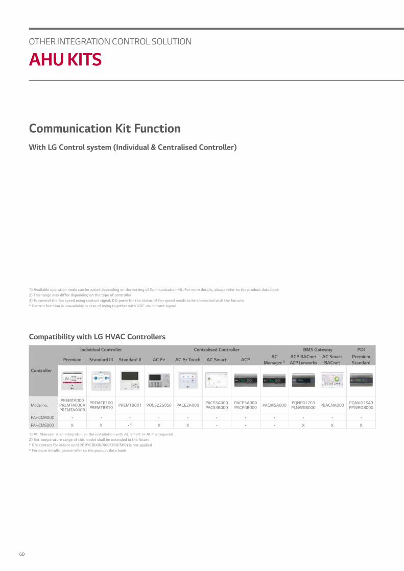
Communication Kit FunctionWith LG Control system (Individual & Centralised Controller)
Compatibility with LG HVAC Controllers
Controller
Individual Controller Centralised Controller BMS Gateway PDI
Premium Standard III Standard II AC Ez AC Ez Touch AC Smart ACP ACManager 1)
ACP BACnetACP Lonworks
AC SmartBACnet
PremiumStandard
Model no.PREMTA000
PREMTA000APREMTA000B
PREMTB100 PREMTBB10 PREMTB001 PQCSZ250S0 PACEZA000 PACS5A000
PACS4B000PACP5A000 PACP4B000 PACM5A000 PQNFB17C0
PLNWKB000 PBACNA000 PQNUD1S40 PPWRDB000
PAHCMR000 • • • • • • • • • • •
PAHCMS000 X X • 2) X X • • • X X X
OTHER INTEGRATION CONTROL SOLUTION
AHU KITS
60

CON
TROL
SOLU
TION
* Table of the outdoor unit compatibility is based on European regional model.When connecting outdoor units in other areas, please check whether they are compatible or not.
Communication Kit FunctionOutdoor Unit CompatibilityMulti V
Single Split
ModelMULTI V MULTI V WATER
5 IV III S IV II S
AHU ControllerPAHCMR000 • • • • • • •
PAHCMS000 • • • • • • X
* Capacities are based on the following conditions :- Cooling : Indoor 27°C(80.6°F) DB / 19°C(66.2°F) WB Outdoor 35°C(95°F) DB / 24°C(75.2°F) WB
Condensing temperature (tc) 46°C, Subcool (SC) 3 K, Evaporating temperature (te) 6°C, Superheat (SH) 5 K- Heating : Indoor 20°C(68°F) DB / 15°C(59°F) WB Outdoor 7°C(44.6°F) DB / 6°C(42.8°F) WB
Hot gas inlet temperature 70°C, Condensing temperature (tc) 46°C, Subcool (SC) 3 K- Piping Length : Interconnected Pipe Length = 7.5m- Difference Limit of Elevation (Outdoor ~ Indoor Unit) is zero
Expansion valves for MULTI V system
EEV KitPRLK096A0
PRLK048A0
Cooling (kW) 3.6 4.5 5.6 7.1 8.2 10.6 12.3 14.1 15.8 22.4 28 33.6 39.2 44.8 50.4 56
Heating (kW) 4 5 6.3 8 9.2 11.9 13.8 15.9 18 25.2 31.5 37.8 44.1 50.4 56.7 63
TXV Kit
PATX50A0E
PATX35A0E
PATX25A0E
PATX20A0E
PATX13A0E
Cooling (kW) 22.4 ~ 44.8 50.4 ~ 72.8 78.4 ~ 100.8 106.4 ~ 128.8 134.4 ~ 156.8
Heating (kW) 25.2 ~ 50.4 56.7 ~ 81.9 88.2 ~ 112.1 118.4 ~ 143.6 148.5 ~ 175.1
Standard Inverter (1-phase)
CapacityCooling kW 4.7 7.7 8.0 10.0 12.5 13.9 14.6
Heating kW 5.5 8.0 9.0 11.0 14.0 15.4 16.9
AHU KitPAHCMR000 • • • • • • •
PAHCMS000 • • • - - - -
Standard Inverter (3-phase)
CapacityCooling kW 10.0 12.5 13.9 14.6 19.0 23.0
Heating kW 11.0 14.0 15.4 16.9 22.4 27.0
AHU KitPAHCMR000 • • • • • •
PAHCMS000 - - - - • •
61LG Multi V 5 Air Conditioners - Control Solution & Accessories

List Required Specification Apply Location
Temperature Sensor - Power : AC 24V, Output signal : DC 0 ~ 10V- Temperature boundary : -50 ~ 50°C - Apply to MA, SA, RA
Temperature & Humidity Sensor- Power : AC 24V, Output signal : DC 0 ~ 10V- Temperature boundary : -40 ~ 70°C- Humidity boundary : 0 ~ 95% RH
- Apply to SA, RA, OA- Can not be applied to MA
Damper Actuator- Power : AC 24V, In/Output signal : DC 0 ~ 10V- Torque : 15 Nm, Operation time : 150sec.- Rotation angle : 90°
- Apply to OA, EA, MA damper
Difference Pressure Sensor (for Filter)- Power : AC 24V, Output signal : DC 0 ~ 10V * Boundary : 0 ~ 1000Pa- Switch type : Relay Open / Close
- Apply to filter
Static Pressure Sensor - Power : AC 24V, Output signal : DC 0 ~ 10V - Boundary : 0 ~ 1000pa - Apply to SA (for inverter control)
CO2 Sensor - Power : AC 24V, Output signal : DC 0 ~ 10V
- Boundary : 0 ~ 2000ppm - Apply to RA duct
Smoke Detection Sensor - Power : AC 24V, From : Contact point type - Apply to RA duct
List Required ItemHeating / Cooling SA / RA temperature sensor (or SA / RA temperature & humidity sensor)
Automatic Ventilation SA / RA temperature, CO2 sensor, Damper actuator (OA, EA, MA)
Energy Saving (Cooling Mode Only) SA temperature, OA / RA temp&humidity sensor, Damper actuator (OA, EA, MA)
Humidification SA temperature, RA temperature & humidity sensor, Humidifier
Inverter Fan Control SA / RA temperature, Static pressure sensor, Inverter driver for fan control
Filter Alarm Difference pressure sensor
Smoke Detecting Smoke detection sensor
Control Kit
RA : Return Air, EA : Exhaust Air, OA : Outdoor Air, SA : Supply Air, MA : Mix air (RA + OA)
Field Supplied Item
Note : Boundary of specification can be changed through LGAV software. However, please make a specification referring to the above table
OTHER INTEGRATION CONTROL SOLUTION
AHU KITS
62

CON
TROL
SOLU
TION
Various Control with Control kit – Multiple MULTI Vs + TXV Kits
Refrigerant Piping
Thermistor (Pipe Temp.)Communication Wire
Signal (DC 0 ~ 10V)Signal (On / Off)
Temperature Sensor- Return Air, Supply Air (Essential)- Mixed Air
Temp & Humidity Sensor- Return Air / Supply Air / Outdoor Air
Damper Actuator- Exhaust Air / Outdoor Air / Mixed Air
Differential Pressure Switch
Valve for Humidifier
CO2 Sensor
Smoke Detector
Fan- Supply / Return
Wired Remote Controller
Local Control Kit
Air Handling Unit Expansion Kit
Control Kit
63LG Multi V 5 Air Conditioners - Control Solution & Accessories

ACCESSORIES
MECHANICAL ACCESSORIES / PIPING ACCESSORIES


Stylish designed panels make more unique space by various applications
4 Way CassettePT-UQC / PT-UMC1
2 Way CassettePT-USC
1 Way Cassette (Grill Type)PT-UUC
Features• Independent vane operation uses separate motors, making it Possible to control all four vanes independently.• The detachable corner design makes it easy to adjust the hanger during installation and to check for leakages
in the drain connection pipe.
UnibodyShape
(No Inlet Line)620mm
620mm
Compact and Stylish Design• New 4 way cassette panel adapted unibody shape and matching with into the ceiling • Panel size is fit into the ceiling tile
Model name Suction Type Color(RAL) Gloss Weight
(kg)Dimension (mm) Applied model
W H D SINGLE SPLIT MULTI SPLIT MULTI V
4 WayPT-UQC Horizontal Grill Morning Fog (RAL 120-4) X 3.0 700 22 700 2.5 ~ 5.0kw 1.5 ~ 5.0kw 1.5 ~ 5.0kw
PT-UMC1 Horizontal Grill Morning Fog (RAL 120-4) X 5.6 950 25 950 7.1 ~ 15.0kw 7.1kw 7.1 ~ 14.0kw
2 Way PT-USC Grill Morning Fog (RAL 120-4) X 4.7 1,100 33 690 - - 5.0 ~ 7.1kw
1 Way PT-UUC Grill Noble White (RAL 110-1) O 4.6 1,100 34 500 - - 2.1 ~ 3.5kw
Specifications
MECHANICAL ACCESSORIES
CASSETTE PANEL
66

ACC
ESSORIES
Drains away condensed water
ABDPGPBDP9
Features• In some places where natural drainage is not possible, a drain pump is very useful to pump out condensed water
from indoor units.• Drain pump assembly (AC 220 ~ 240V, 50 / 60Hz)
Models Applied• Ceiling Concealed Duct (Refer to PDB for applicable models)
Accessory Model NameCeiling Concealed Duct (Refer to PDB for applicable models)
Product Model Drain Pump
SINGLE / MULTI SPLIT
H-INVERTER Included
Standard Inverter
CB**L Included
CM** / UM** ABDPG
UB70 / UB85 PBDP9
Compact Inverter ABDPG
MULTI V Included
ApplicationHigh head drain pump automatically drains water up to 700mm of drain-head height.It provides perfect solution for water drainage.
High Head Drain Pump
* Included in H-Inverter* Supplied as accessory for Standard Inverter (ABDPG/ PBDP9)
Drain Pipe Slope (1/50~1/100)
Fixture
450mm
300mm
700mm
Flexible Drain Hose
Drain pipe
MECHANICAL ACCESSORIES
DRAIN PUMP KIT
67LG Multi V 5 Air Conditioners - Control Solution & Accessories

CO2 sensor in ventilation system.
PES-C0RV0
Standard Wired Remote Controller
CO2 Sensor(PES-C0RV0)
Time (min)
1,000
0
2,500
WindowsClosed
WindowsClosed
WindowsOpen
WindowsOpen
CO2 (
ppm
)
ERV with CO2 Concentration Control
Installation Scene
Features
CO2 Sensor Reading ERV Fan Operation<500ppm Off
500 ~ 700ppm Low Speed
700 ~ 900ppm High Speed
>900ppm Super High Speed
• Specification• Applied Model : ERV, ERV DX• Function
- Supply Vottage : DV 12V 5%- Output : 0 ~ 5V
(Linear output, 1 ~ 2,000ppm CO2)- Accuracy : 30ppm 5% of reading
• DescriptionThe product is especially designed to detect CO2
concentration in ERV system.
• Operation Table
MECHANICAL ACCESSORIES
CO2 SENSOR
68

ACC
ESSORIES
AHCS100H0
Features• Specification
• Applied Model : ERV (Default), ERV DX (Optional)• Supply voltage : DV12V 5%• Output : 0.6 ~ 4.4V (Linear output, 240 ~ 1,760 ppm CO2)• Accuracy : 10% (2 days after installation)
• Description• The product is especially designed to detect CO• This model requires Standard III Wired Remote Controller for display
CO2 Sensor Reading ERV Fan Operation<500ppm Off
500 ~ 700ppm Low Speed
700 ~ 900ppm High Speed
>900ppm Super High Speed
• Operation Table
Time (min)
1,000
0
2,500
WindowsClosed
WindowsClosed
WindowsOpen
WindowsOpen
CO2 (
ppm
)
ERV with CO2 Concentration Control
Installation Scene
Standard III WiredRemote Controller
CO2 Sensor (AHCS100H0) Embedded inside of ERV
69LG Multi V 5 Air Conditioners - Control Solution & Accessories

R410A refrigerant leakage detector makes our space safer
PRLDNVS0
Features• This detector senses refrigerant leakage and when the refrigerant concentration exceeds 6,000ppm not only
it will stop indoor unit operation, but also it will give an alarm using buzzer and sensor LED.(The green and red LED lights blink simultaneously.)
• Alarm is “ON” over 6,000ppm has been maintained 5 seconds, and on the contrary to this, Alarm is “OFF” under 6,000ppm has been maintained 5 seconds.
• When the alarm of the refrigerant leak detector is switched on the user must ventilate until the alarm is disabled. • The detector has to be installed inside the room and it can be installed 300 ~ 500mm from floor.
Refrigerant Leakage
Senses Refrigerant Leakage
Stop Operation and Ring Alarm
1
2
3
Application
Parts Specifications
Sensor
Rated Voltage (V) DC 5.0 5%
Dimensions (W x H x D, mm) 31 x 44 x 20
Weight (g) 22
Detectable Refrigerant R410A
Detected Concentration (ppm) 0 / 6,000 Alarm Off / On
Operating Temperature Range (oC) -10 ~ 50
Preserved Temperature Range (oC) - 40 ~ 60
Average Power Consumption (mA) 35
Connecting Cable Cable Length (m) 10
Sensor Protective CoverDimensions of Front Plate (W x H x D, mm) 80 x 110 x 44.6
Dimension of Backplate (W x H x D, mm) 80 x 110 x 6.5
Specifications
MECHANICAL ACCESSORIES
REFRIGERANT LEAKAGE DETECTOR
70

ACC
ESSORIES
MULTI V EEV KIT is specially designed to reduce noise and make comfort environment
PRGK024A0
Note : If you don’t use EEV of same specification, Cooling (Heating) capacity may decrease.
Features• Decreasing noise level of Multi V Indoor units Easy installation
Application
Models Applied• Ceiling Cassette (up to 4.5kW) • Ceiling concealed duct (up to 5.6kW)• Wall mounted (up to 7.1kW) • Console (up to 4.5kW)• Floor Standing Unit (with case / without case) (up to 4.5kW)• Convertible (up to 3.6kW, Ceiling Suspended Type is not able to connect this Kit) * Fresh Air intake Unit is not able to connect this Kit
Outdoor Unit
Outdoor UnitEEV Kit
EEV Kit
Indoor unit
Indoor unit
Indoor Heat Exchanger
Fan
C / Box
ElectronicExpansion Valve
COMPHeat exchanger
Fan M
M
PipeWireRefrigerant flow (Cooling)Refrigerant flow (Heating)
MECHANICAL ACCESSORIES
EEV KIT
71LG Multi V 5 Air Conditioners - Control Solution & Accessories

IR RECEIVER can be connected to CCD where the customer wants to control by wireless remote controller
PWLRVN000
Features• Designed for wireless control to operate Ceiling concealed duct Operation of Indication lamp (3 colors) Self-diagnosis function
Models Applied• MULTI V Indoors (Ceiling concealed duct, Floor standing units)
Application
Note : Do not install both the IR Receiver and Wired Remote Controller. This may cause malfunctions.
Wired RemoteController IR Receiver
Wireless RemoteController(Standard)
MECHANICAL ACCESSORIES
IR RECEIVER
72

ACC
ESSORIES
EEV full close function in case of power cut
PRIP0
FeaturesIndependent Power Module is specially designed to close the Indoor EEV at power cut-Off.- Supply Voltage : DC 12V 50%
Models Applied• MULTI V Indoors
Power Plug
Power Plug
Main Switch
Main Switch
A/CSwitch
A/CSwitch
Switch BOX
Switch BOX
1st
1st
2nd
2nd
3rd
3rd
4th
3 Phase400V
1 Phase220V
Each room
Independent Power Module (Option)
Each room
Independent Power Module (Option)
Outdoor UnitOutdoor Unit
MECHANICAL ACCESSORIES
INDEPENDENT POWER MODULE
73LG Multi V 5 Air Conditioners - Control Solution & Accessories

Mechanical Accessories Line up and ApplicationModel name SINGLE SPLIT MULTI MULTI V RemarkY Branch and Header Branch (Synchro) • - - -
Branch Distributor (MULTI) - • - MULTI F DX systems
Y Branch and Branch Kit (MULTI) - • - MULTI F DX systems
New Heat Recovery Unit (Multi V) - - • MULTI V 5
Hear Recovery Unit (Multi V) - - •MULTI V 5 / MULTI V IV HR / MULTI V III HR
MULTI V S HR / MULTI V SYNC II / MULTI V SYNC MULTI V WATER IV HR / MULTI V WATER II HR
Y Branch and Header Branch (MULTI V) - - • Various type of MULTI V Series
SINGLE SPLIT MULTI SPLIT MULTI V
Y Branch and Header Branch(Synchro)
Branch Distributor Heat Recovery Unit
PMBD3620PMBD3630PMBD3640
PRHR022PRHR032PRHR042
Y Branch and Branch Kit New Heat Recovery Unit
2 UnitsPMUB11A
3 Units PMUB111A
4 UnitsPMUB1111A
2 UnitsPMBL3620PMBL5620
2 UnitsPMBL1203F0
PRHR023PRHR033PRHR043PRHR063PRHR083
Y Branch and Header Branch
PIPING ACCESSORIES
LINE-UP
74

ACC
ESSORIES
Refrigerant distribution channel
Features• Various Y Branch pipes of different capacities make installation easier• Y Branch and header branch for both gas and liquid are provided• Insulation material is also provided for covering the branches
Models Applied• H-inverter : 10.0 / 12.5 / 13.4kw• Standard inverter : 12.5 / 14.0 / 15.0 / 20.0 / 25.0kw
Gas Pipe Liquid Pipe
Application
2 Branch 3 Branch 4 Branch
Accessory Model NameModel name SINGLE SPLIT Remark2 Units PMUB11A 50:50 (1:1)
3 Units PMUB111A 33:33:33 (1:1:1)
4 Units PMUB1111A 25:25:25:25 (1:1:1:1)
a b c TypeA Ø15.88 (5/8) Ø19.05 (3/4) Ø25.4 (1) 1
B Ø9.52 (3/8)Ø12.7 (1/2)
Ø12.7 (1/2)Ø15.88 (5/8) - 2
C Ø6.35 (1/4) Ø9.52 (3/8) - 2
D Ø9.52 (3/8) Ø12.7 (1/2) - 2
2 UNITSPMUB11A
3 UNITSPMUB111A
4 UNITSPMUB1111A
PIPING ACCESSORIES
Y BRANCH AND HEADER BRANCH
75LG Multi V 5 Air Conditioners - Control Solution & Accessories

Effective way of distributing refrigerant
PMBD3620PMBD3630PMBD3640
Features• Distribution of refrigerant to various indoor units• 3 models (2, 3, 4 indoor units)• Consists of LEVs inside it• Controlling PCB inside the unit
• Internally insulated (Prevents any chances of drainage)• Flare joints for easy and clean installation• Compact design (Low height)• Flexible installation
Models Applied• MULTI F DX systems (Refer to PDB for applicable models)
Model Name PMBD3620 PMBD3630 PMBD3640Connectable Indoor Units Number of Indoor Units 1~2 1~3 1~4
Capacity (Btu/hr) 5k / 7k / 9k / 12k / 18k / 24k 5k / 7k / 9k / 12k / 18k / 24k 5k / 7k/9k / 12k / 18k / 24k
Casing Colour Paintingless Paintingless Paintingless
Power Source Ø / V / Hz 1 / 220-240 / 50 1 / 200-240 / 50 1 / 200-240 / 50
Power Consumption (W) 10 10 10
Running Current (A) 0.05 0.05 0.05
Dimensions (W x H x D) (mm) 302 x 143 x 252 302 x 143 x 252 302 x 143 x 252
Packing Dimensions (W x H x D) (mm) 422 x 202 x 300 422 x 202 x 300 422 x 202 x 300
Net Weight 4.8 4.9 5.0
Connecting CableIndoor Unit No. x mm² 4 x 0.75 4 x 0.75 4 x 0.75
Outdoor Unit No. x mm² 4 x 0.75 4 x 0.75 4 x 0.75
Piping Connection(Outdoor Unit)
liquid (mm) 9.52 9.52 9.52
Gas (mm) 19.05 19.05 19.05
Piping Connection(Indoor Unit)
Liquid (mm) 6.35 x 2 6.35 x 3 6.35 x 4
Gas (mm) 9.52 x 2 9.52 x 3 9.52 x 4
Parts
Hanger (EA) 4 4 4
Screw (EA) 8 8 8
Manual (EA) 1 1 1
Models Applied
Parts Included• BD (Banch Distributor) unit (1EA) • Brackets (4EA)• Screws (8EA) • Installation Manual (1EA)
PIPING ACCESSORIES
BRANCH DISTRIBUTOR DISTRIBUTOR BOX
76

ACC
ESSORIES
Refrigerant distribution channel
2 UNITSPMBL3620 / PMBL5620
2 UNITSPMBL1203F0
Features• Y Branch and Branch kit make Multi F DX installation easier• Y Branch and Branch kit for both gas and liquid are provided• Insulation material is also provided for covering the branches
Models Applied• MULTI F DX systems (refer to PDB for applicable models)
Parts Included• Y Branch for gas side and liquid side (1set) • Installation manual (1EA)
Application
Accessory Model Name(Unit : mm)
Model Name No. of Branch Distribution Units Applicable Model
SpecificationsGas Liquid
PMBL3620 2 units Only 3ø, 36k Btu/h
PMBL5620 2 units 1ø, 3ø
PMBL1203F0 3 units 1ø, 3ø
Ø 15.88 Ø 15.88
Ø 15.88
Ø 6.35 Ø 6.35
Ø 6.35
Ø 19.05 Ø 19.05
Ø 19.05
Ø 9.52 Ø 9.52
Ø 9.52
Ø 15.88 Ø 15.88
Ø 15.88
Ø 6.35 Ø 6.35
Ø 6.35
Ø 19.05 Ø 19.05
Ø 19.05
Ø 9.52 Ø 9.52
Ø 9.52
Ø 15.88 Ø 15.88
Ø 15.88
Ø 6.35 Ø 6.35
Ø 6.35
Ø 19.05 Ø 19.05
Ø 19.05
Ø 9.52 Ø 9.52
Ø 9.52
Ø 15.88 Ø 15.88
Ø 15.88
Ø 6.35 Ø 6.35
Ø 6.35
Ø 19.05 Ø 19.05
Ø 19.05
Ø 9.52 Ø 9.52
Ø 9.52
Ø 9.52Ø19.05 Ø 9.52Ø 9.52Ø19.05 Ø 9.52
PIPING ACCESSORIES
Y BRANCH AND BRANCH KIT MULTI F DX
77LG Multi V 5 Air Conditioners - Control Solution & Accessories

PRHR022 (2 branch Unit)PRHR032 (3 branch Unit)PRHR042 (4 branch Unit)
Features• Max. 32 indoor units can be connected (Max. 8 indoor units per branch)• It is easy to install due to the automatic search algorithm for piping detection• Subcooling cycle in HR unit makes the system efficiency maximum
Models Applied• MULTI V 5 • MULTI V IV Heat Recovery • MULTI V III Heat Recovery • MULTI V SYNC II • MULTI V SYNC • MULTI V WATER IV Heat Recovery• MULTI V WATER II Heat Recovery • MULTI V S Heat Recovery
Parts Included• HR unit (1EA) • Hanging bolts M10 or M8 (4EA) • Nut M8 or M10 (8EA)• Washers M10 (8EA) • Reducers
Model name PRHR022 PRHR032 PRHR042
Number of Branch EA 2 3 4
Maximum Connectable Capacity of Indoor Units (Per branch / unit) kW 16 / 32 16 / 48 16 / 58
Maximum Number of Connectable Indoor units per Branch EA 8 8 8
Nominal InputCooling kW 0.026 0.040 0.040
Heating kW 0.026 0.040 0.040
Net. Weight kg 18 20 22
Dimensions (W x H x D) mm 831 x 218 x 617 831 x 218 x 617 831 x 218 x 617
Pipingconnections
Indoor UnitLiquid mm (inch) 9.52 (3/8) 9.52 (3/8) 9.52 (3/8)
Gas mm (inch) 15.88 (5/8) 15.88 (5/8) 15.88 (5/8)
Outdoor Unit
Liquid mm (inch) 9.52 (3/8) 12.7 (1/2) 15.88 (5/8)
Low pressure mm (inch) 22.2 (7/8) 28.58 (11/8) 28.58 (11/8)
High Pressure mm (inch) 19.05 (3/4) 22.2 (7/8) 22.2 (7/8)
Power supply Ø / V / Hz 1 / 220-240 / 501 / 220 / 60
1 / 220-240 / 501 / 220 / 60
1 / 220-240 / 501 / 220 / 60
Specifications
PIPING ACCESSORIES
HEAT RECOVERY UNIT
78

ACC
ESSORIES
Convenient Free ZoningMULTI V Heat Recovery provides flexible control over individual zones for the user’s convenience
• Individual Control- Perfect individual control over spaces ventilation needed
• Zone Control- Max. of 8 indoor units can be connected for one branch- Max. of 32 indoor units can be connected for one HR unit- Same opeational model can be operated by indoor units
with zone control function installed
• Combination of Individual and Zoning Installations- Flexible piping design
• Save Product and Installation Cost
Reducers for Indoor Unit and HR Unit
[Zoning Control]
HR Unit
Zoning Control (Max Indoor Unit 8EA)
(Unit : mm)
Model Name Liquid High pressure Low pressure
Indoor Unit Reducer
HR Unit Reducer
PRHR022
PRHR032 / PRHR042
Office
Room
Kitchen
IT Room
79LG Multi V 5 Air Conditioners - Control Solution & Accessories

PRHR023 (2 Branch Unit)PRHR033 (3 Branch Unit)PRHR043 (4 Branch Unit)PRHR063 (6 Branch Unit)PRHR083 (8 Branch Unit)
Features• Max. 64 indoor units can be connected (Max. 8 indoor units per branch)• It is easy to install due to the automatic search algorithm for piping detection• Subcooling cycle in HR unit makes the system efficiency maximum
Models Applied• MULTI V 5 Heat Recovery
Parts Included• HR unit (1EA) • Hanging bolts M10 or M8 (4EA) • Nut M8 or M10 (8EA)• Washers M10 (8EA) • Reducers
Model name PRHR023 PRHR033 PRHR043 PRHR063 PRHR083Number of Branch EA 2 3 4 6 8
Maximum Connectable Capacity of Indoor Units (Per branch / unit) kW 17.5/35 17.5/52.5 17.5/69.5 17.5/69.5 17.5/69.5
Maximum Number of Connectable Indoor units per Branch EA 8 8 8 8 8
Nominal InputCooling kW 0.040 0.040 0.040 0.076 0.076
Heating kW 0.038 0.038 0.038 0.072 0.072
Net. Weight kg 18.5 20.3 22.0 28.3 31.8
Dimensions (W x H x D) mm 786 x 218 x 657 786 x 218 x 657 786 x 218 x 657 1,113 x 218 x 657 1,113 x 218 x 657
Pipingconnections
Indoor UnitLiquid mm (inch) 9.52 (3/8) 9.52 (3/8) 9.52 (3/8) 9.52 (3/8) 9.52 (3/8)
Gas mm (inch) 15.88 (5/8) 15.88 (5/8) 15.88 (5/8) 15.88 (5/8) 15.88 (5/8)
Outdoor Unit
Liquid mm (inch) 9.52 (3/8) 12.7 (1/2) 15.88 (5/8) 15.88 (5/8) 15.88 (5/8)
Low pressure mm (inch) 22.2 (7/8) 28.58 (11/8) 28.58 (11/8) 28.58 (11/8) 28.58 (11/8)
High Pressure mm (inch) 19.05 (3/4) 22.2 (7/8) 22.2 (7/8) 22.2 (7/8) 22.2 (7/8)
Power supply Ø / V / Hz 1 / 220-240 / 501 / 220 / 60
1 / 220-240 / 501 / 220 / 60
1 / 220-240 / 501 / 220 / 60
1 / 220-240 / 501 / 220 / 60
1 / 220-240 / 501 / 220 / 60
Specifications
PIPING ACCESSORIES
NEW HEAT RECOVERY UNIT
80

ACC
ESSORIES
Convenient Free ZoningMULTI V Heat Recovery provides flexible control over individual zones for the user’s convenience
• Individual Control- Perfect individual control over spaces ventilation needed
• Zone Control- Max. of 8 indoor units can be connected for one branch- Max. of 64 indoor units can be connected for one HR unit- Same opeational model can be operated by indoor units
with zone control function installed
• Combination of Individual and Zoning Installations- Flexible piping design
• Save Product and Installation Cost
Reducers for Indoor Unit and HR Unit
[Zoning Control]
HR Unit
Zoning Control (Max Indoor Unit 8EA)
(Unit : mm)
Model Name Liquid High pressure Low pressure
Indoor Unit Reducer
HR Unit Reducer
PRHR023
PRHR033PRHR043PRHR063 PRHR083
Office
Room
Kitchen
IT Room
81LG Multi V 5 Air Conditioners - Control Solution & Accessories

Improving Service WorkabilityCan inspect valves and PCBs under the product.(looking up at the product)
Conventional New
At least 450 mm of space is required to open the control cover and to inspect or repair the product.
min 450mm
The control cover can be opened(disassembled) in the downward direction. → Error code check and simple check & repair are possible.
Inspection door
Control Cover
Expansion of connection capacity• Expansion of connection capacity per port : (old) 15kW (new) 17kW• Expansion of total connectable capacity : (old) 60kW (new) 71.87kW
Previous Model New
4 ports
Max 60kW Max 71.87kW
8 ports
15kW / port 17kW / port
PIPING ACCESSORIES
NEW HEAT RECOVERY UNIT
82

ACC
ESSORIES
Easy Series ConnectionSeries connection can be installed without pipes crossing.
Series connectionin the same direction
Series connectionin the reverse direction
Crossedpiping
Reduce NoiseCooling Heating changeover noise improvement
Conventional New
13dBdB(A)
Conventional New
83LG Multi V 5 Air Conditioners - Control Solution & Accessories
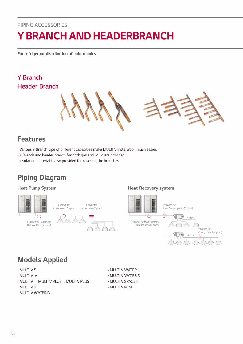
Y BranchHeader Branch
Features• Various Y Branch pipe of different capacities make MULTI V installation much easier.• Y Branch and header branch for both gas and liquid are provided.• Insulation material is also provided for covering the branches.
Models Applied• MULTI V 5 • MULTI V IV • MULTI V III, MULTI V PLUS II, MULTI V PLUS• MULTI V S• MULTI V WATER IV
Piping DiagramHeat Pump System
Y Branch for Heat Pump Outdoor Units (2 Pipes)
Y branch for indoor units (2 pipes)
Header for indoor units (2 pipes)
For refrigerant distribution of indoor units
HR unit
Y branch for Heat Recovery units (3 pipes)
Y branch for Zoning control (2 pipes)
HR unit
Y branch for Heat Recovery outdoor units (3 pipes)
Heat Recovery system
• MULTI V WATER II• MULTI V WATER S• MULTI V SPACE II• MULTI V MINI
PIPING ACCESSORIES
Y BRANCH AND HEADERBRANCH
84
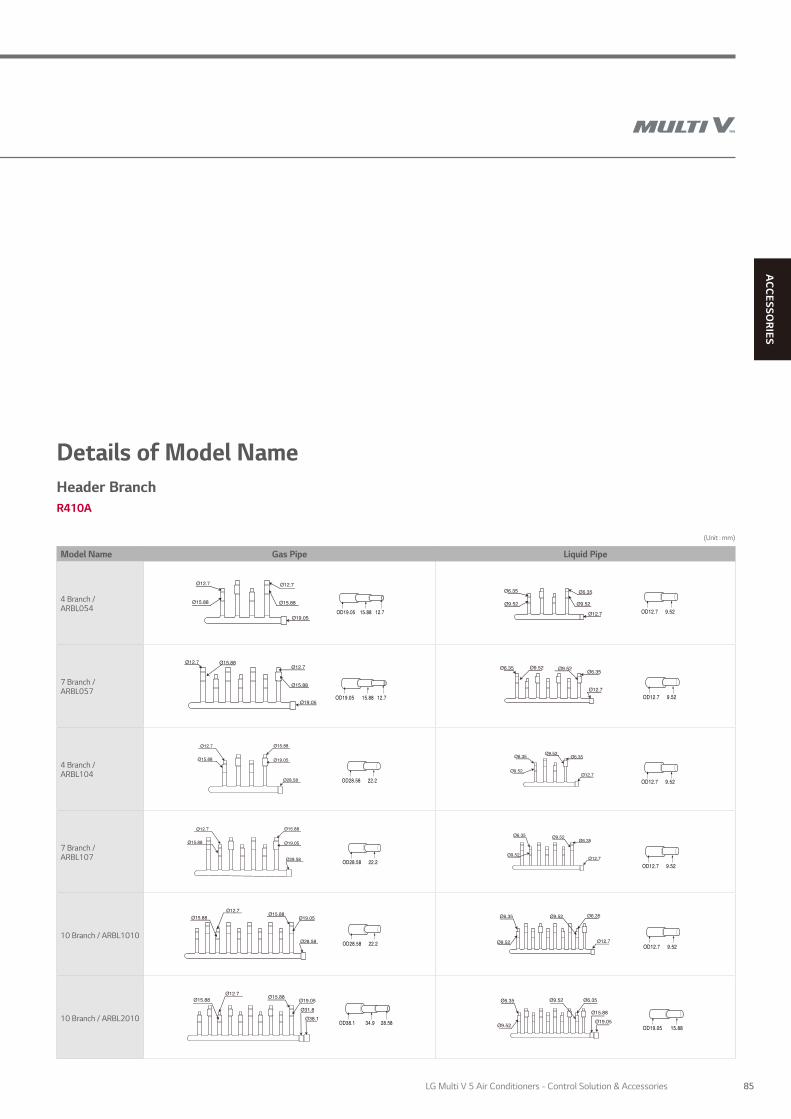
ACC
ESSORIES
Details of Model NameHeader BranchR410A
(Unit : mm)
Model Name Gas Pipe Liquid Pipe
4 Branch /ARBL054
7 Branch /ARBL057
4 Branch /ARBL104
7 Branch /ARBL107
10 Branch / ARBL1010
10 Branch / ARBL2010
85LG Multi V 5 Air Conditioners - Control Solution & Accessories

Y Branch pipe for connection of outdoor units
Heat PumpR410A MULTI V 5, MULTI V IV, MULTI V III, MULTI V WATER IV, MULTI V WATER II
3 Outdoor Units
Model Name High Pressure Gas Pipe Liquid Pipe
ARCNN31
Liquid Pipe High Pressure Gas Pipe
341
111
298
I.D.34.9I.D.41.3
I.D.28.58
I.D.44.5I.D.41.3O.D.34.9
O.D.41.3I.D.44.5I.D.53.98
I.D.22.2O.D.28.58I.D.34.9
111
130
416408
I.D.28.58 I.D.28.58
I.D.34.9
I.D.41.3 I.D.38.1 O.D.34.9
I.D.31.8I.D.22.2
I.D.28.58
I.D.34.9O.D.28.58I.D.22.2
O.D.41.3I.D.44.5I.D.53.98
I.D.22.2O.D.28.58I.D. 34.9
83
334281
I.D.15.88
I.D.19.05 I.D.19.05
I.D.12.7
I.D.22.2
I.D.28.58I.D.22.2O.D.19.05
O.D.22.2I.D.28.58I.D.31.8
I.D.19.05O.D.15.88
I.D.15.88 I.D.15.88
I.D.15.88
I.D.19.05 I.D.12.7
I.D.12.7
I.D.9.52
331
83
70
314
I.D.22.2 O.D.19.05
O.D.12.7 I.D.9.52
I.D. 19.05O.D.15.88
I.D. 19.05O.D.15.88
111
416408
I.D.28.58 I.D.28.58
I.D.34.9I.D.31.8I.D.22.2
I.D.28.58
I.D. 19.05I.D.22.2
O.D.28.58
O.D. 22.2 I.D. 19.05
334281
I.D.15.88
I.D.19.05 I.D.19.05
I.D.12.7
83I.D.22.2
I.D.22.2O.D.19.05
I.D.19.05O.D.15.88
I.D.28.58 O.D.22.2
I.D.12.7I.D.15.88
O.D.19.05
(Unit : mm)
2 Outdoor Units
Model Name High Pressure Gas Pipe Liquid Pipe
ARCNN21
Liquid Pipe High Pressure Gas Pipe
341
111
298
I.D.34.9I.D.41.3
I.D.28.58
I.D.44.5I.D.41.3O.D.34.9
O.D.41.3I.D.44.5I.D.53.98
I.D.22.2O.D.28.58I.D.34.9
111
130
416408
I.D.28.58 I.D.28.58
I.D.34.9
I.D.41.3 I.D.38.1 O.D.34.9
I.D.31.8I.D.22.2
I.D.28.58
I.D.34.9O.D.28.58I.D.22.2
O.D.41.3I.D.44.5I.D.53.98
I.D.22.2O.D.28.58I.D. 34.9
83
334281
I.D.15.88
I.D.19.05 I.D.19.05
I.D.12.7
I.D.22.2
I.D.28.58I.D.22.2O.D.19.05
O.D.22.2I.D.28.58I.D.31.8
I.D.19.05O.D.15.88
I.D.15.88 I.D.15.88
I.D.15.88
I.D.19.05 I.D.12.7
I.D.12.7
I.D.9.52
331
83
70
314
I.D.22.2 O.D.19.05
O.D.12.7 I.D.9.52
I.D. 19.05O.D.15.88
I.D. 19.05O.D.15.88
111
416408
I.D.28.58 I.D.28.58
I.D.34.9I.D.31.8I.D.22.2
I.D.28.58
I.D. 19.05I.D.22.2
O.D.28.58
O.D. 22.2 I.D. 19.05
334281
I.D.15.88
I.D.19.05 I.D.19.05
I.D.12.7
83I.D.22.2
I.D.22.2O.D.19.05
I.D.19.05O.D.15.88
I.D.28.58 O.D.22.2
I.D.12.7I.D.15.88
O.D.19.05
4 Outdoor Units
Model Name High Pressure Gas Pipe Liquid Pipe
ARCNN41
Liquid Pipe High Pressure Gas Pipe
341
111
298
I.D.34.9I.D.41.3
I.D.28.58
I.D.44.5I.D.41.3O.D.34.9
O.D.41.3I.D.44.5I.D.53.98
I.D.22.2O.D.28.58I.D.34.9
111
130
416408
I.D.28.58 I.D.28.58
I.D.34.9
I.D.41.3 I.D.38.1 O.D.34.9
I.D.31.8I.D.22.2
I.D.28.58
I.D.34.9O.D.28.58I.D.22.2
O.D.41.3I.D.44.5I.D.53.98
I.D.22.2O.D.28.58I.D. 34.9
83
334281
I.D.15.88
I.D.19.05 I.D.19.05
I.D.12.7
I.D.22.2
I.D.28.58I.D.22.2O.D.19.05
O.D.22.2I.D.28.58I.D.31.8
I.D.19.05O.D.15.88
I.D.15.88 I.D.15.88
I.D.15.88
I.D.19.05 I.D.12.7
I.D.12.7
I.D.9.52
331
83
70
314
I.D.22.2 O.D.19.05
O.D.12.7 I.D.9.52
I.D. 19.05O.D.15.88
I.D. 19.05O.D.15.88
111
416408
I.D.28.58 I.D.28.58
I.D.34.9I.D.31.8I.D.22.2
I.D.28.58
I.D. 19.05I.D.22.2
O.D.28.58
O.D. 22.2 I.D. 19.05
334281
I.D.15.88
I.D.19.05 I.D.19.05
I.D.12.7
83I.D.22.2
I.D.22.2O.D.19.05
I.D.19.05O.D.15.88
I.D.28.58 O.D.22.2
I.D.12.7I.D.15.88
O.D.19.05
PIPING ACCESSORIES
PIPING ACCESSORIES
86

ACC
ESSORIES
Heat RecoveryR410A MULTI V 5, MULTI V IV Heat Recovery, MULTI V III Heat Recovery, MULTI V WATER IV Heat Recovery, MULTI V WATER II Heat Recovery
3 Outdoor Units
Model Name High Pressure Gas Pipe Liquid Pipe Low Pressure Gas Pipe
ARCNB31
(Unit : mm)
2 Outdoor Units
Model Name High Pressure Gas Pipe Liquid Pipe Low Pressure Gas Pipe
ARCNB21
Low Pressure Gas Pipe Liquid Pipe High Pressure Gas Pipe
111
130
416408
I.D.28.58 I.D.28.58
I.D.34.9
I.D.41.3 I.D.38.1 O.D.34.9
I.D.31.8I.D.22.2
I.D.28.58
I.D.34.9O.D. 28.58I.D.22.2
I.D.34.9O.D.28.58I.D.22.2
134
415375
I.D.44.48 I.D.53.98 I.D.41.3
I.D.28.58
I.D.53.98I.D.44.5O.D.41.3
I.D.34.9O.D.28.58I.D.22.2
341
111
298
I.D.34.9I.D.41.3
I.D.28.58
I.D.44.5I.D.41.3O.D.34.9
O.D.41.3I.D.44.5I.D.53.98
I.D.22.2O.D.28.58I.D.34.9
111
130
416408
I.D.28.58 I.D.28.58
I.D.34.9
I.D.41.3 I.D.38.1 O.D.34.9
I.D.31.8I.D.22.2
I.D.28.58
I.D.34.9O.D.28.58I.D.22.2
O.D.41.3I.D.44.5I.D.53.98
I.D.22.2O.D.28.58I.D. 34.9
334281
I.D.15.88
I.D.19.05 I.D.19.05
I.D.12.7
83I.D.22.2
I.D.28.58I.D.22.2O.D.19.05
O.D.22.2I.D.28.58I.D.31.8
I.D.19.05O.D.15.88
I.D.15.88 I.D.15.88
I.D.15.88
I.D.19.05 I.D.12.7
I.D.12.7
I.D.9.52
331
83
70
314
I.D.22.2 O.D.19.05
O.D.12.7 I.D.9.52
I.D. 19.05O.D.15.88
I.D. 19.05O.D.15.88
125
I.D.41.3 O.D.34.9
341
111
298
I.D.34.9I.D.41.3
I.D.28.58
I.D.34.9O.D.28.58I.D.22.2
O.D.41.3I.D. 44.5I.D.53.98
O.D.34.9 I.D.28.58
111
416408
I.D.28.58 I.D.28.58
I.D.34.9I.D.31.8I.D.22.2
I.D.28.58
I.D. 19.05I.D.22.2
O.D.28.58
O.D. 22.2 I.D. 19.05
334281
I.D.15.88
I.D.19.05 I.D.19.05
I.D.12.7
83I.D.22.2
I.D.22.2O.D.19.05
I.D.19.05O.D.15.88
I.D.28.58 O.D.22.2
I.D.12.7I.D.15.88
O.D.19.05
4 Outdoor UnitsModel Name High Pressure Gas Pipe Liquid Pipe Low Pressure Gas Pipe
ARCNB41
Low Pressure Gas Pipe Liquid Pipe High Pressure Gas Pipe
111
130
416408
I.D.28.58 I.D.28.58
I.D.34.9
I.D.41.3 I.D.38.1 O.D.34.9
I.D.31.8I.D.22.2
I.D.28.58
I.D.34.9O.D. 28.58I.D.22.2
I.D.34.9O.D.28.58I.D.22.2
134
415375
I.D.44.48 I.D.53.98 I.D.41.3
I.D.28.58
I.D.53.98I.D.44.5O.D.41.3
I.D.34.9O.D.28.58I.D.22.2
341
111
298
I.D.34.9I.D.41.3
I.D.28.58
I.D.44.5I.D.41.3O.D.34.9
O.D.41.3I.D.44.5I.D.53.98
I.D.22.2O.D.28.58I.D.34.9
111
130
416408
I.D.28.58 I.D.28.58
I.D.34.9
I.D.41.3 I.D.38.1 O.D.34.9
I.D.31.8I.D.22.2
I.D.28.58
I.D.34.9O.D.28.58I.D.22.2
O.D.41.3I.D.44.5I.D.53.98
I.D.22.2O.D.28.58I.D. 34.9
334281
I.D.15.88
I.D.19.05 I.D.19.05
I.D.12.7
83I.D.22.2
I.D.28.58I.D.22.2O.D.19.05
O.D.22.2I.D.28.58I.D.31.8
I.D.19.05O.D.15.88
I.D.15.88 I.D.15.88
I.D.15.88
I.D.19.05 I.D.12.7
I.D.12.7
I.D.9.52
331
83
70
314
I.D.22.2 O.D.19.05
O.D.12.7 I.D.9.52
I.D. 19.05O.D.15.88
I.D. 19.05O.D.15.88
125
I.D.41.3 O.D.34.9
341
111
298
I.D.34.9I.D.41.3
I.D.28.58
I.D.34.9O.D.28.58I.D.22.2
O.D.41.3I.D. 44.5I.D.53.98
O.D.34.9 I.D.28.58
111
416408
I.D.28.58 I.D.28.58
I.D.34.9I.D.31.8I.D.22.2
I.D.28.58
I.D. 19.05I.D.22.2
O.D.28.58
O.D. 22.2 I.D. 19.05
334281
I.D.15.88
I.D.19.05 I.D.19.05
I.D.12.7
83I.D.22.2
I.D.22.2O.D.19.05
I.D.19.05O.D.15.88
I.D.28.58 O.D.22.2
I.D.12.7I.D.15.88
O.D.19.05
87LG Multi V 5 Air Conditioners - Control Solution & Accessories

Y Branch pipe for connection of outdoor units
Model Name Gas Pipe Liquid Pipe
ARBLN07121
ARBLN14521
I.D28.58
I.D31.8
I.D34.9O.D31.8
I.D28.58I.D31.8 O.D22.2
I.D22.2O.D19.05 I.D28.58
I.D19.05 I.D15.88
I.D12.7
I.D15.88I.D22.2
I.D19.05
I.D12.7 I.D15.88
I.D19.05
I.D15.88
I.D19.05
I.D12.7
I.D12.7
I.D19.05I.D15.88
I.D9.52O.D12.7 I.D6.35
I.D9.52O.D12.7
I.D38.1I.D41.3 O.D34.9I.D41.3
O.D38.1
I.D19.05O.D22.2 I.D15.88 I.D12.7
O.D15.88 I.D22.2O.D28.58 I.D19.05
I.D34.9 I.D41.3
I.D38.1
I.D38.1
I.D34.9
I.D28.58
I.D28.58
I.D22.2I.D34.9
Model Name Gas Pipe Liquid Pipe
ARBLN23220
(Unit : mm)
Model Name Gas Pipe Liquid Pipe
ARBLN01621
ARBLN03321
I.D9.52
I.D12.7
I.D9.52 I.D6.35
I.D12.7
I.D9.52
I.D12.7
I.D6.35
O.D19.05I.D 22.2 I.D 22.2
O.D19.05
I.D25.4
I.D28.58
I.D19.05I.D22.2 I.D15.88 I.D19.05
I.D12.7
I.D12.7I.D15.88
I.D19.05
I.D25.4
O.D19.05
I.D12.7O.D9.52
I.D9.52
I.D6.35
I.D9.52 I.D6.35
I.D. 9.52 I.D6.35
I.D12.7 I.D15.88
I.D12.7 I.D15.88I.D19.05O.D15.88
I.D15.88
I.D15.88
Heat Pump, Heat Recovery zone controlR410A MULTI V 5, MULTI V IV, MULTI V III, MULTI V PLUS II, MULTI V PLUS, MULTI V S, MULTI V MINI, MULTI V SPACE II, MULTI V WATER IV, MULTI V WATER S, MULTI V WATER II
PIPING ACCESSORIES
PIPING ACCESSORIES
88

ACC
ESSORIES
(Unit : mm)
Model Name High Pressure Gas Pipe Liquid Pipe Low Pressure Gas Pipe
ARBLB01621
ARBLB03321
ARBLB07121
ARBLB14521
Model Name High Pressure Gas Pipe Liquid Pipe Low Pressure Gas Pipe
ARBLB23220
I.D12.7 I.D15.88
I.D12.7 I.D15.88I.D19.05O.D15.88
I.D15.88
I.D12.7O.D9.52
I.D9.52
I.D6.35
I.D9.52 I.D6.35
I.D. 9.52 I.D6.35
O.D19.05I.D 22.2 I.D 22.2
O.D19.05
I.D25.4
I.D28.58
I.D19.05I.D22.2 I.D15.88 I.D19.05
I.D12.7
I.D12.7I.D15.88
I.D19.05
I.D25.4
O.D19.05
I.D9.52
I.D12.7
I.D9.52 I.D6.35
I.D12.7
I.D9.52
I.D12.7
I.D6.35
I.D28.58
I.D31.8
I.D34.9O.D31.8
I.D28.58
I.D31.8 O.D22.2
I.D22.2
O.D19.05 I.D28.58
I.D19.05 I.D15.88
I.D12.7
I.D15.88I.D22.2
I.D19.05
I.D12.7 I.D15.88
I.D19.05
I.D15.88
I.D19.05
I.D12.7
I.D12.7
I.D19.05I.D15.88
I.D9.52
O.D12.7 I.D6.35
I.D9.52
O.D12.7
I.D38.1
I.D41.3 O.D34.9I.D41.3O.D38.1
I.D19.05
O.D22.2 I.D15.88 I.D12.7
O.D15.88 I.D22.2
O.D28.58 I.D19.05
I.D34.9 I.D41.3
I.D38.1
I.D38.1
I.D34.9
I.D28.58
I.D28.58
I.D22.2I.D34.9
I.D.53.98
12
3
333
2 2
33
I.D.34.9 I.D31.8
I.D.28.58I.D.53.98 I.D.25.4 I.D.22.2
I.D.15.88I.D.19.05I.D12.7
X2 X2
175 100
12070
115
O.D.38.1 O.D.44.48O.D.44.48
O.D15.88 O.D.22. 2
O.D.28.58
I.D.44.48
I.D.44.48I.D.44.48
I.D41.3
I.D41.3
I.D38.1
I.D38.1 134
420
490
Heat RecoveryR410A MULTI V 5, MULTI V IV Heat Recovery, MULTI V III Heat Recovery, MULTI V WATER IV Heat Recovery, MULTI V WATER II Heat Recovery
2
3
332
I.D.22.2
I.D.22.2
I.D.15.88 I.D19.52I.D.12.7 I.D6.35O.D.19.05 O.D12.7
I.D.19.05 96
346379
110 110
I.D22.2I.D25.4I.D.25.4
I.D.25.4
I.D.19.05
X2
3
33
3
2
2
2
I.D34.9
I.D38.1
I.D19.05I.D15.88 I.D41.3 I.D38.1
I.D41.3
I.D19.05
O.D38.1 O.D34.9O.D22.2
O.D15.88
O.D28.58I.D12.7 I.D22.2
I.D.41.3 I.D38.1
I.D34.9 I.D22.2 125
471 517
120
120
13090
70
I.D28.58
I.D28.58
I.D34.9
89LG Multi V 5 Air Conditioners - Control Solution & Accessories

MEMO
90

91LG Multi V 5 Air Conditioners - Control Solution & Accessories

Find out morelg.com/au/commercial-air-conditioning