control system overview - fujitsu general america, inc
TRANSCRIPT

50
Remote Controls
Service & Monitoring
Simple Remote ControlUTY-RHRY
Withoutoperation mode
Withoperation mode
Wireless Remote ControlUTY-LNHU
Touch Remote ControlUTY-RNRUZ1
Wired Remote ControlUTY-RNKU
Simple Remote ControlUTY-RSRY
Service ToolUTY-ASGXZ1
SoftwareSoftware Web Monitoring SystemUTY-AMGXZ1
Indoor unit
Transmission line
USB adapter(Field supplied)
Outdoor unit
Web Monitoring Tool
VRF Network System SideMonitoring SideMonitoring Side
Internet
VRF Network System Side
For AII AIRSTAGETM series
pg. 53
pg. 55
pg. 55
pg. 55
pg. 56
Wi-fi INterface ModuleFJ-RC-WIFI-1NA
pg. 57
pg. 72pg. 70
USB adapter
*2
Internet
Indoor unit
Transmission line
Outdoor unit
Control system overview

51
VRF
Central Controllers
BMS Communication Options
USB Adaptor*2
System ControllerUTY-APGXZ1UTY-ALGXZ1(Lite edition)
Touch Panel ControllerUTY-DTGYZ1
BACnet® GatewayUTY-ABGXZ1
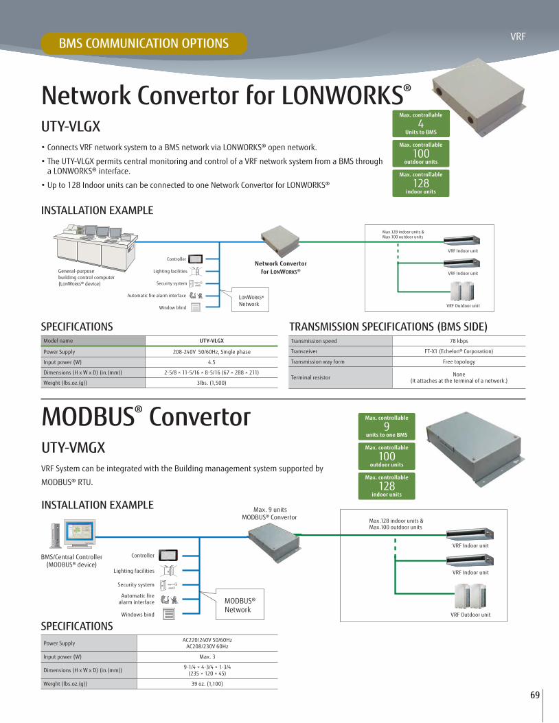
Network Convertor (BMS / LONWORKS®)UTY-VLGX
MODBUS® ConvertorUTY-VMGX
Central Remote ControllerUTY-DCGY
(Field supplied)
USB Adaptor*2
(Field supplied)
Software
Software
BMS/BAS
Accessories
Single splitSU MO TU WE TH FR SA
7
3 126 9 15 18 21
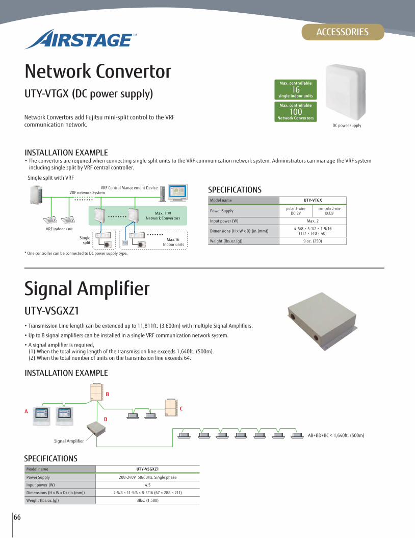
Network Convertor
UTY-VTGXDC power supply type
*1
*1. BMS/BAS: Building Management System / Building Automation System*2. USB Adaptor is U10 USB Network Interface of Echelon® Corporation.
Remote / Monitoring side
Internet
Signal AmplifierUTY-VSGXZ1
(
External Switch ControllerUTY-TERX
Card-key
(Field supplied)
IR Receiver UnitUTB-YWC
IR receiver UnitUTY-LRHYB1
pg. 62
pg. 59
pg. 61
pg. 68
BACnet® Gateway (Hardware)UTY-VBGX
pg. 68
pg. 69
pg. 69
pg. 66
pg. 67
pg. 56
pg. 56
pg. 66

52
REMOTES CONTROLLERS
ItemTouch Remote
Control
Wired RemoteControl
Simple RemoteControl
Simple Remote
Control*1
Wireless RemoteControl
Wi-fi Interface Module
Central Controller
TouchPanel
Controller
System Controller Lite
Software
System Controller
Software
Model name UTY-RNRUZ1 UTY-RNKU UTY-RSRY UTY-RHRY UTY-LNHU FJ-RC-WIFI-1NA UTY-DCGY UTY-DTGYZ1 UTY-ALGXZ1 UTY-APGXZ1
Max. controllable remote control groups 1 1 1 1 1 1 100 400 400 1600
Max. controllable indoor units 16 16 16 16 16 1 100 400 400 1600
Max. controllable groups - - - - 16 - 16 100 400 1600
Air c
ondi
tioni
ng c
ontr
ol fu
nctio
n
On / Off •*3 • • • • • • • • •Operation mode setting • • • - • • • • • •Fan speed setting • • • • • • • • • •Room temp. setting • • • • • • • • • •Room temp. set point limitation • - • • - • • • • •Test operation • • • • • • • • - -
Up/down air direction flap setting • • • • • • • • • •Right/left air direction flap setting • • - - • • • • • •Individual louver control • - - - - - - • - -
Group setting - - - - - - • • • •RC prohibition - - - - - - • • • •Anti freeze setting - - - - - • • • • •Set temp. auto return • • - - - • - - - -
Away setting • - - - - • - - - -
Economy mode setting • • - - • • • • • •Occupancy sensor control - - - - - - - - • •
Disp
lay
Error • • • • - • • • • •Defrosting • • • • - • • • • •Current time • • - - • • • • • •Day of week • • - - - - - • • •R.C. prohibition • • • • - - • • • •Cooling/heating priority • • • • - • • • • •Address display • • • • - - • • • •Room temp • - • • - • - - - -
Multi language • - - - - • • • • •Daylight Saving Time setting (Summer) • - - - - - • • • •Time zone setting - - - - - - - • - -
Name registration • - - - - • • • • •Backlight • - • • - • • • - -
2D floor layout / 3D building display - - - - - - - - - •
Tim
er
Schedule timerPeriod Week Week - - - Unlimited Week Year Year Year
On/Off, Temp, mode, times per day 8*3 *4 4 - - - Unlimited 20 20 144 144
On/off timer - • - - • • - - - -
Sleep timer - - - - • • - - - -
Program timer - - - - • • - - - -
Auto off timer • - - - - • - - - -
Day off • • - - - • • • • •Min. unit of timer setting (Minutes) 10 · 30 30 - - 5 - 10 10 10 10
Cont
rol
Status monitoring system - - - - - - • • • •Electricity charge apportionment - - - - - - - - •Error history • • - - - - • • • •Emergency stop - - - - - - •*2 •*2 - -
Remote management - - - - - • - - •Energy saving management - - - - - - - -
Low noise mode - - - - - - - • - -
Inte
rnet E-mail notification for malfunction - - - - - - - - • •
Key lock •Child lock - - - - •Password
setting
•Passwordsetting
•Passwordsetting
•Passwordsetting
•Passwordsetting
BMS
Third party Modbus communication - - - - - - - -
*1 “Operation mode” setting is not available for this model. *2 This function is available only through external input. control. *3 On / Off (Occupied / Unoccupied) *4 Mode deleted •: Supported : Optional function — : Not supported yet
Comparison Table of Remotes & Controllers
53
VRF
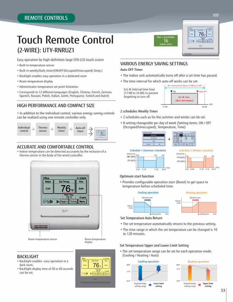
Touch Remote Control(2-WIRE): UTY-RNRUZ1
HIGH PERFORMANCE AND COMPACT SIZE• In addition to the individual control, various energy saving controls can be realized using one remote controller only.
VARIOUS ENERGY SAVING SETTINGSAuto OFF Timer
• The indoor unit automatically turns off after a set time has passed.
• The time interval for which auto off works can be set.
• 2 schedules such as for the summer and winter can be set.
• 8 setting changeable per day of week (Setting items: ON / OFF (Occupied/Unoccupied), Temperature, Time)
Optimum start function
temperature before scheduled time.
Set Temperature Auto Return
• The set temperature automatically returns to the previous setting.
• The time range in which the set temperature can be changed is 10 to 120 minutes.
Set Temperature Upper and Lower Limit Setting
• The set temperature range can be set for each operation mode. (Cooling / Heating / Auto)
ACCURATE AND COMFORTABLE CONTROL• Indoor temperature can be detected accurately by the inclusion of a
thermo sensor in the body of the wired controller.
BACKLIGHT• Backlight enables easy operation in a
dark room.• Backlight display time of 30 or 60 seconds
can be set.
Individualcontrol
Thermosensor timer
Auto off timer
Ex) At interval time hour (17:00 to 24:00) to prevent forgetting to turn off
Schedule 1 (Summer schedule)
Cooling operation
Cooling operation
Schedule 2 (Winter schedule)
Heating operation
Heating operation
Room temperature sensor Room temperature display
Set interval time hour (17:00 to 24:00)
Set off time
(30 to 240 minutes)
17:00 24:00
ON Auto OFF
OFF
80°F (26°C)
75°F (24°C)
ON
8:40 11:40 17:30 20:40
OFF OFF
Time
Setting temp.
77°F (25°C)
73°F (23°C)
ONSetting temp.
8:40 10:00 17:3015:30 20:40
OFF OFF
Time
Setting temp.
Operation start
Setting time Time Time
Setting temp.
Operation start
Setting time
Original temp.setting range
Lower limitsetting
88°F
77°F
64°FOriginal temp.setting range
Upper limitsetting
88°F
77°F
50°F
Max. controllable
indoor units16
• Built-in temperature sensor
• Built-in weekly/Daily timer(ON/OFF(Occupied/Unoccupied),Temp.)
• Backlight enables easy operation in a darkened room
• Room temperature display
• Administrator temperature set point limitation
• Corresponds to 12 different languages (English, Chinese, French, German, Spanish, Russian, Polish, Italian, Greek, Portuguese, Turkish and Dutch)
REMOTE CONTROLS

54
Displays setting status and Limitations
• The remote controller settings can be easily checked
EASY MAINTENANCEError History Display
• The errors that occur in the indoor unit or remote control are saved.
• A maximum of 32 error incidents can be saved.
SPECIFICATIONS
Uses non-polar 2-wire type
• The faulty wiring can be prevented by using non-polar 2-wire.
• Reduce errors and install time compared with manual addressing
SIMPLIFIED INSTALLATION
ADDITIONAL FUNCTIONSAway mode
• Cooling / Heating is automatically started when the room temperature reaches a setting temperature even if the indoor unit is off.
Daylight savings time (Summer Time)
• Provides Daylight Savings adjustment option for regions that uses it.
Name registration
• Indoor unit names can be registered in the remote control screen. This makes it easy to identify the indoor unit.
• Lock / unlock method: Push the ON/OFF button and the screen (4 seconds)
Model name UTY-RNRUZ1
Power source DC 12V
Input Power 4-3/4 × 4-3/4 × 13/16 (120 x 120 x 20.4)
Airflow Rate 8 (220)
DC12V is supplied by the indoor unit.
Automatically stop
Heat functionset
Room temp.
Automatically start
Setting temp.
In summer
Setback-Heat function operation
Setting temp.
Room temp.
Automatically stop
Cool function set
Automatically start
In winter
Setback-Cool function operation
OK OK
non-polar 2-wire
Y1 Y2 Y1 Y2
I.U. Y1 Y2 Y3 I.U. Y1 Y2 Y3
1 2 3 4
The appropriate indoor unitperforms the air blow and LED lamps blink.
UTY-RNRUZ1 cont'd
REMOTE CONTROLS

55
VRF
Simple Remote Control(2-WIRE) UTY-RSRY / UTY-RHRY (WITHOUT OPERATION MODE)
Max. controllable
indoor units16
VERTICAL LOUVER CONTROLOffers vertical louver movement control for ducted and cassette units.
Withoutoperation mode
Withoperation mode
ROOM TEMPERATURE SET POINT LIMITATIONThe Simple Remote Control can manage set point limitation in small buildings without the central controller requirement.
During Cooling During Heating88°F
77°F
64°F
88°F
77°F
50°F
Compact wired remote control unit provides access to basic functions
• Built-in temperature sensor
• Backlit display
• Equipped with Remote control prohibition
• Suitable for hotels, classrooms or offices as it is easily operated with no complex functions.
SPECIFICATIONSModel name UTY-RNKU UTY-RSRY UTY-RHRY
Power Supply DC 12V DC 12V DC 12V
Dimensions (H x W x D) (in.(mm)) 4-3/4 × 4-3/4 × 11/16 (120 × 120 × 18) 4-3/4 × 2-15/16 × 9/16 (120 × 75 × 14) 4-3/4 × 2-15/16 × 9/16 (120 × 75 × 14)
Weight (oz.(g)) 6 (160) 4 (120) 4 (120)
DC12V is supplied by the indoor unit.
Wired Remote Control (3-WIRE) UTY-RNKUThe room temperature can be controlled by detecting the temperature accurately from the built-in sensor
• Simple operation with Built-in Weekly / Daily Timer.
• Control up to 16 indoor units.
• Up to 2 wired remote controls can be connected to a single indoor unit.
Max. controllable
indoor units16
ACCURATE AND COMFORTABLEIndoor temperature can be detected accurately by the inclusion of a thermo sensor in the body of the wired controller.
This wired remote controller and the optional remote sensor allows flexibility in sensor location, suitable for all requirements.
Example of changing sensor:
BUILT-IN TIMERSA weekly timer with up to four different On/Off and temperature settings per day
SIMPLE INSTALLATION
Designed for flush mount or usage of standard electric box.Remote Sensor in the bedroom
Wired remotecontroller
Indoor unit
Remotesensor
The detecting pointcan be easily changed
Day Night
Displayed temperature is set temperature.
Wired Remote Controller in the living room
REMOTE CONTROLS
UTY-RSRY UTY-RHRY

56
Max. controllable
indoor units16
Selectable
daily timers4
ADDRESS SETTINGDuring installation, address setting can be performed using the Wireless Remote Control, thus eliminating manual switch setting.
Simple and sophisticated operations with a choice of 4 daily timers
• A single controller controls up to 16 indoor units.
ACCURATE AND COMFORTABLESelect from 4 different timer programs: On / Off / Program / Sleep
Program timer: The program timer operates the ON and OFF timer once within a 24 hour period.
Sleep timer: The sleep timer function automatically corrects the set temperature according to the time setting to prevent excessive cooling or heating during sleep hours.
EASY INSTALLATION AND OPERATION• Code selector switch prevents indoor unit mix-up. (Up to 4 codes
can be set.)
• Wide and precise transmitting range.
and wall mounted indoor units.
Transmission line
Outdoor unit
WirelessRemote Controller
Indoor unit
RB unit
Wireless Remote ControlUTY-LNHU
REMOTE CONTROLS
IR RECEIVER UNIT : UTB-YWCNecessary to control all duct types by Wireless Remote Control
IR RECEIVER UNIT : UTY-LRHYB1Cassette type indoor unit can be controlled with Wireless Remote Control
IR Receiver Unit
Duct type indoor unit
WirelessRemote Controller
WirelessRemote Controller IR Receiver Unit

57
VRF
For:CassettesDucted UnitsCeiling MountFloor/Ceiling Mount (Universal)Wall Mounted
WI-FI INTERFACE FOR VRFControl your fujitsu airstage VRF indoor unit from anywhere
HOW DOES IT WORK?
• The indoor units are controlled from a webpage or using an iOS or Android APP in a very intuitive way.
• A wired device installed near each unit controls its operation and
• A server in the cloud manages the whole process.
Local control
Standard Wi-Fi b/g/n router
Cloud System
From everywhere
IOS and Android APPS
Using any web browser
Remotely manage your VRF indoor unit using a smartphone, tablet or PC via the Internet.
FEATURES• Manages the VRF indoor unit using the iOS or Android app.
• Programs the indoor unit operation schedule.
• Offers access to several indoor unit settings including Mode, temperature set point, and much more.
• Offers early startup that brings the space to the desired set point before arriving.
• Also, offers delayed setback after leaving.
• Error reporting, available in several languages
Wi-fi Interface ModuleFJ-RC-WIFI-1NA
REMOTE CONTROLS

58
Enclosure UL Approval ABS (UL 94HB)
Dimensions 2-3/4 x 4-1/4 x 1-1/8 (70 x 108 x 28)
Weight 0.17 lbs (80g)
Color White
Power Supply 12V, 55mA Can be powered through indoor unit.
Mounting Wall
LED indicators 1 x Device status
Operating Temperature 32°F ~ 104°F (0°C ~ 40°C)
Operating humidity <93% HR, no condensation
RoHS conformity Compliant with RoHS directive (2002/95/CE).
• EN 60950-1 • EN 301489-1 v1.8.1 • EN 301489-17 v2.1.1
Type Indoor Unit Model Required Parts
Compact Wall Mounted (ASUA)7, 9, 12, 14RLAV Plug model:
K9707476019*7, 9, 12, 14TLAV
Wall Mounted (ASUB)18, 24RLAV Plub model:
K9709223017*18, 24TLAV
Compact Cassette (AUUA)7, 9, 12, 14, 18, 24RLAV
Built-in Low voltage terminal block
7, 9, 12, 14, 18, 24TLAV
Cassette (AUUB)18, 24, 30, 36RLAV18, 24, 30, 36TLAV
Floor/Ceiling (ABUA)12, 14, 18, 24RLAV12, 14, 18, 24TLAV
Ceiling (ABUA)30, 36RLAV30, 36TLAV
Slim Duct (ARUL)7, 9, 12, 14, 18RLAV7, 9, 12, 14, 18TLAV
Medium Static Pressure Duct (ARUM)24, 30, 36RLAV24, 30, 36TLAV
High Static Pressure Duct (ARUH)36, 48, 60RLAV36, 48, 60, 72, 96TLAV
Vertical Air Handler (ARUV) 12, 18, 24, 30, 36, 48, 60TLAV
*Plug included with indoor wall mount units
FJ-RC-WIFI-1NA cont'dCOMPATIBILITY FOR WIRED WI-FI MODULE
TECHNICAL FEATURES

59
VRF
Touch Panel Controller with Internet UTY-DTGYZ1
Max. controllable
indoor units400High visibility and easy operation via high resolution 7.5 inch TFT-LCD touch panel screen
• Controls up to 400 indoor units*• Provides Internet/LAN remote control and operation• Indoor units can be grouped for batch monitoring and setting• Schedules are programmable with up to 20 settings per day• Easy-to-understand Graphical User Interface (GUI)• Data can be transfered to USB for further analysis
• Large-sized 7.5-inch no-glare TFT color touch screen• Selectable 2 display types (Icon / List) in monitoring mode• Supports 7 different-languages ,English, Chinese, French, German, Spanish, Russian, Polish.
* For Heat Recovery network systems the limit is 320 indoor units, consult the D&T manual for
EASY MAINTENANCE• Flat touch screen is easily cleaned
• Non-glare coating on touch panel
• Easy-to-remove front cover
FUNCTIONS
2
2015
Restaurant
REMOTE MONITORING AND OPERATION FUNCTIONS• Internet/LAN remote monitoring and control of the VRF system using a web browser. (Operation status monitoring, Operation mode setting,
and Error history display)
• Automatically emails errors.
VRFnetwork systemOperation mode setting
Operation status monitoring
LANor
Internet
Error notification by E-mailTablet
PC
T bl t
EASY OPERATION• Easy-to-understand icon-driven Graphical User Interface (GUI)
pen by pressing the appropriate on-screen icon
• Up-to-date status display
monitoring, green for operational control
OPTIONAL: ELECTRICITY CHARGE APPORTIONMENTElectricity Charge Apportionment optional add-on USB drive can be added to help users be energy aware and help building owners apply sub-tenant billing.
• UTY-PTGXA must be ordered separately
CENTRAL CONTROLLERS

60
SPECIFICATIONSPower Supply 100-240V 50/60Hz, Single phase
Dimensions (H x W x D) (in.(mm)) 10-1/4 × 9-11/16 × 2-1/8 (260 × 246 × 54)
Weight (lbs.(g)) 5 (2150)
Interface Transmission / LAN / USB / EXT IN / EXT OUT / Reset SW
UP TO 400 INDOOR UNITS CAN BE CONTROLLED
Group A Group B
Emergency stop controlAir conditioner can be turned off through the external input control
It allows multiple indoor unit grouping
Emergency stop function
FUNCTION• Up to 400 indoor units can be controlled
• Multiple indoor units can be grouped and controlled
• Schedule timer function is standard (20 patterns per day)
• Emergency stop function(through the external input control)
• Temperature upper and lower limit setting
Individual control Flexible grouping
Schedule control Indoor units operation monitoring
AUTOMATIC CLOCK ADJUSTMENTThe time setting of each remote control can be set in batch automatically.
VERSATILITY• Emergency stop function: Air conditioner can be turned off through
the external input control
• The stored data can be transferred to USB port
• CSV format data edited by PC can be imported to Touch Panel Controller.
Data transfer availableby USB
EASY INSTALLATION• Touch Panel Controller does not require mounting an additional
power supply.
• No additional components are required for installation.
UTY-DTGYZ1 cont'd
CENTRAL CONTROLLERS

61
VRF
Central ControllerUTY-DCGY
• Individual control and monitor of up to 100 indoor units
• 5 inch TFT color screen
• User friendly view and easy operation
• External input / output contact
• Detachable power supply unit
• Corresponds to 7 different languages like English, Chinese, French, German, Spanish, Russian, Polish.
Max. controllable
indoor units100
Max. controllable
groups16
EASY INSTALLATION• The control panel and power supply unit can be installed
separately.
• For flexibility in installation, the control panel can be built into the wall or flush mounted.
FUNCTIONS• Diverse control of indoor units • Weekly timer
• Automatic clock adjustment • Error history
SPECIFICATIONSControl Panel Power Supply Unit
Power Supply DC 5V 100-240V, 50-60Hz, Single phase
Dimensions (H x W x D) (in.(mm)) 4-3/4 × 6-3/8 × 1 (120 × 162 × 25.7) 3-7/8 × 5-5/16 × 1-9/16 (99 × 135 × 39.2)
Weight (oz.(g)) 11 (308) 13 (355)
Packing List Control Panel / Power Supply Unit / Connecting cable, etc.
Group : Division A Group : Division B
Group : Hallway
Group : Division C
Group : 3F
Emergency stop function
Group : Tenant A Group : Tenant B Group : Tenant C
Group : 2F
SYSTEM OVERVIEW• It allows multiple indoor units grouping (Max.16 groups controlled)
• Interlock with external device
Control panel + Power supply unit
Control panel
Control panel
CeilingPower supply unit
Power supply unit
Wall
Wall
Setting pattern 1 Setting pattern 2
CENTRAL CONTROLLERS

62
System ControllerUTY-APGXZ1 Software System Controller provides the advanced integrated monitoring & control of
• Up to a maximum of 4 VRF network systems, 1600 indoor units, and 400 outdoor units can be controlled.
• In addition to air conditioning precision control function, central remote control, electricity charge calculation, schedule management, and energy saving functions are strengthened and building manager and owner needs are met.
Max. controllable
4
Max. controllable
outdoor units400
Max. controllable
indoor units1,600
System Controller LiteUTY-ALGXZ1 Software
System Controller Lite is designed for small and medium scale buildings.
• Controls up to a maximum of 1 VRF network system, 400 indoor units, and 100 outdoor units.
• In addition to air conditioning precision control function, a variety of management software add-ons are available as options to give customers a wide range of choice.
USER FRIENDLY VIEW AND OPERATION: The building can be viewed and controlled in a 3D
click-able perspective view. Four different views are available: site,
Indoor units can be freely grouped for simple batched control from a BMS tree menu. Grouping by hierarchal structure, such as by section, division or department is possible.
Site view
Building view
Floor view
List view
Properties can be shown using one of the four displays of site, building, floor, or list.
The floor layout drawing can be imported to easily make the settings for the actual building.
Site view List view
Floor view
Batched control of freelydefined groups
Click & Operate the whole building ! Click & Operate any specified unit(s)!
Click & Operate the unit !
The display is easily changed by pressing the button.
Batched control of freely selected units
Click & Operate the whole floor !
Click & Operate the whole floor !
Note: 2D floor layout / 3D building display are not available for System Controller Lite.
CENTRAL CONTROLLERS
Max. controllable
1
Max. controllable
outdoor units100
Max. controllable
indoor units400

63
VRF
ELECTRICITY CHARGE APPORTIONMENT Standard for System Controller Option for System Controller Lite UTY-PLGXA1
DIVERSE OPERATION MANAGEMENT & DATA MANAGEMENTSchedule management
• Annual schedules can be set for each remote control group / user defined group.
• Start / stop, operating mode, remote control prohibition, and temperature settings can be set up to 143 times per day at 10 minute intervals for up to 101 configurations for each remote controller group.
• Allows programming of special settings for holidays, including public holidays, for a complete year.
• Low noise operation of outdoor unit can be scheduled.
Diverse control of indoor unit
• Indoor unit operation state, operation mode, etc. are displayed
• Indoor unit start / stop and operation mode switching
• Room temperature set point limitation
Remote control prohibition
This prohibits changes to the operation mode, temperature, start/stop, etc.
The time setting of each controller can be set in batch automatically.
Errors provide popup messages, audible sound and e-mails. Errors for the past year are logged and can be reviewed later.
Database import/export
Imports/exports registration data, layout data, and image data.
Only the administrator can use this setting.
Operating & control record
Displays the history of operation status and control.
3Ø, 4 wire 400V, 50Hz
Signal transmission lineRB Unit
1Ø, 2wire 230V, 50Hz
System Controller
Outdoorunit
Tenant A-1 Tenant A-2 Tenant A-3
Tenant A-4 Tenant A-5 Tenant A-6
Tenant B-1 Tenant B-2 Tenant B-3
Tenant C-1 Tenant C-2 Tenant C-3
PowPoweP rdistribuibubutiontion
boardd
PowPoweP rdistribuibubutiontion
boardd
Electricity charges (air conditioning)Electric power company
3RD PARTY DEVICES CONNECTED BY MODBUS CAN BE CONTROLLED Standard for System Controller Option for System Controller Lite UTY-PLGXX2
When Modbus Adaptor (locally purchased) is connected to system controller PC, the devices connected to the Modbus can be centrally controlled.
Lighting facilities
Energy recovery ventilator system
Outdoor air unit system
Supply & Exhaust fanRemote I/O
Supported Modbus communication(Field supply)
System Controller(System Controller Lite)
Electricitymeter Electric power
company
VRF Network
Signal Line
conditioners of each tenant from the electricity charge for each month. With Electricity Charge Apportionment function, used energy apportionment ratio will be provided, calculating in detail the energy consumed by the units used by each tenant. This information is then used to calculate the charges for the electricity consumed for air conditioning by each tenant from the total electricity charges in the
The detailed calculation takes into consideration such things as unused rooms and nighttime electricity charges and shows them in a charges calculation sheet.
CENTRAL CONTROLLERS

64
System Controller may be used on site or remotely over various networks for remote central control. System Controller requires 2 software programs working together. VRF Controller runs on site and communicates with VRF system. VRF Explorer runs remotely and provides user interface and communicates with the VRF Controller. VRF Controller and VRF Explorer programs may run on a single PC or on different PCs. By using VRF Explorer software, one PC can perform central control of 10 VRF system sites with max. 20 buildings per site.
REMOTE MANAGEMENT STANDARD FOR SYSTEM CONTROLLER UTY-PEGXZ1, OPTION FOR SYSTEM CONTROLLER LITE UTY-PLGXR2
PEAK CUT OPERATIONTo control power consumption and load shedding, the system can be programmed to change the indoor unit set temperature, turn the indoor unit thermostat off, or take other measures to carefully control the amount of power consumed while maintaining comfort.
OUTDOOR UNIT CAPACITY SAVEOutdoor unit capacity save switches the outdoor unit capability upper limit to suppress power consumption during hot summers and cold winters by averaging the power saving effect of each refrigerant system. You can select from 50% or more of the capacity upper limit.
INDOOR UNIT ROTATION OPERATIONThe operation of indoor units can be automatically rotated within a group in accordance with the set annual schedule to reduce power consumption while maintaining comfort. The indoor unit operation stoppage rate can be selected.
A variety of energy saving operations can be set and managed depending on the season, weather, and time period. Excellent energy saving operation is performed while keeping users comfortable.
ENERGY SAVING MANAGEMENT OPTION FOR SYSTEM CONTROLLER UTY-PEGXZ1 , OPTION FOR SYSTEM CONTROLLER LITE UTY-PLGXR2
Remote central control and monitor
Building Management Company A (In charge of the day shift)
Building management company,management center, etc.
BuildingManagement Company B
(In charge of the night shift)
Security Company
Headquarters Management Center
A maximum of 10 locations, such as offices or factories
1 VRF Explorer can control or monitor up to 10 sites.
1 VRF Controller can be monitored from any number of VRF Explorers (Up to 5 simultaneous connections).
Office Management Center
VRF Explorer
VRF Explorer
VRF Explorer
VRF ExplorerVRF Explorer
VRF Explorer
VRF Controller
VRF Controller
On site central controlMax. 4 VRF network systems per site
VRF Explorer
VRF Controller
Central Monitoring Screenfor all Properties
Special Property Detailed Monitoring Screen
Internet
Energy saving graph data: This graph compares the electricity consumption with the previous month and previous year to make it easy to analyze the energy saving effect.
Energy Saving Management Main Screen
Forced thermostat off range
Target power consumption
Shows change in power consumption by time
Outdoor unit stop range
Ideal control line (Use of average power consumption)
Indoor unit rotation screenI d it t tiOutdoor unit capacity
control screend
Pow
er c
onsu
mpt
ion
Time
Outdoor unit capacity
upper limit
Hot day ofsummer
Cold day ofwinter
System Controller and System Controller Light (continued) Software
CENTRAL CONTROLLERS
65
VRF
PERSONAL COMPUTER SYSTEM REQUIREMENTS
FUNCTIONS SUMMARY
Model name System Controller System Controller Lite
Operating system
• Microsoft® Windows® 7 Home Premium (32-bit or 64-bit) SP1, Windows® 7 Professional (32-bit or 64-bit) SP1• Microsoft® Windows® 8.1 (32-bit or 64-bit), Windows® 8.1 Pro (32-bit or 64-bit)• Microsoft® Windows® 10 Home (32-bit or 64-bit), Windows® 10 Pro (32-bit or 64-bit)[Supported languages] English, Chinese, French, German, Russian, Spanish, and Polish
CPU Intel® CoreTM i3 2 GHz or higherMemory • 2 GB or more (for Windows Vista® and Windows® 7 [32-bit]) • 4 GB or more (for Windows® 7 [64-bit], Windows® 8.1, and Windows® 10)HDD 40 GB or more of free spaceDisplay 1024 x 768 or higher resolution
Interface
•Ethernet port (for getting access to the Internet using LAN) or Modem (for getting access to the Internet using Public Telephone Line)•USB ports (Maximum of 6 ports) (Required only for the Server PC that works as VRF Controller)- Maximum of 2 USB ports are required for WHITE-USB-KEY/WibuKey connection- Maximum of 4 USB ports are required for Echelon® U10 USB Network Interface* Maximum number of required USB port depends on the applicable system
configuration.
•Ethernet port (for getting access to the Internet using LAN) or Modem (for getting access to the Internet using Public Telephone Line)•USB ports (Maximum of 6 ports) (Required only for the Server PC that works as VRF Controller)- Maximum of 4 USB ports are required for WHITE-USB-KEY/WibuKey connection- 1 USB port is required for Echelon® U10 USB Network Interface* The maximum number of required USB port depends on the applicable system
configuration.Graphic accelerator Microsoft® DirectX® 9.0c compatibleSoftware Adobe® Reader® 9.0 or later•Personal computer that satisfies the following system requirements•Echelon® U10 USB Network Interface (Required for each VRF Network.)
Function TypeSystem controller System controller lite
UTY-APGXZ1 OptionUTY-PEGXZ1
UTY-ALGXZ1 OptionUTY-PLGXR2
OptionUTY-PLGXA2
OptionUTY-PLGXE2
OptionUTY-PLGXX2
System specification
Max. VRF networks supported 4 - 1 - - - -Max. indoor unit / remote controller groups per VRF network 400 - 400 - - - -Max. outdoor units per System controller 100 - 100 - - - -Max. indoor units / remote controller groups per System controller 1600 - 400 - - - -Max. outdoor units per System controller 400 - 100 - - - -
Sitesupervision
Multi site display 10 - 10 - - - -Number of building / 1 site 20 - - - - - -Number of floor per 1 site 200 - - - - - -Number of floor per 1 building 50 - - - - - -3D graphical layout view • - - - - - -2D graphical layout view • - - - - - -List display • - • - - - -Tree display • - • - - - -Group display • - • - - - -
Errormanagement
Error notification • - • - - - -Audible alarm • - • - - - -Error e-mail notification • - • - - - -
HistoryError history • - • - - - -Operation history • - • - - - -Control history • - • - - - -
Operationcontrol
Individualcontrol
On/Off • - • - - - -Operation mode • - • - - - -Room temperature • - • - - - -Fan speed • - • - - - -Air flow direction • - • - - - -Economy mode • - • - - - -Room temperature set point limitation • - • - - - -Test operation • - • - - - -Antifreeze • - • - - - -Outdoor unit low noise setting • •
Individual management
Remote control prohibition setting • - • - - - -Temperature upper and lower limit setting • - • - - - -Filter sign reset • - • - - - -
Other Memory operation • - • - - - -Pattern operation • - • - - - -
Schedule
Annual Schedule • - • - - - -Special day setting • - • - - - -On /off per day 72 - 72 - - - -On / off per week 504 - 504 - - - -Day off • - • - - - -Min. unit of timer setting (Minutes) 10 - 10 - - - -Low noise mode Weekly schedule • - • - - - -
Remotemanagemment
Remote monitoring • - - • - - -Remote operation control • - - • - - -Remote function setting • - - • - - -Web Remote Controller • - - • -
Electricitychargeapportionment
Apportionment charge/bill calculation • - - - • - -Tenant (block) setting • - - - • - -Common facilities apportionment setting • - - - • - -Rated power consumption allotment setting • - - - • - -Individual calculation at cooling and heating - •* - - • - -Electricity meter supported - • - - • - -
Energysavingmanagement
Indoor unit rotation - • - - - • -Peak cut control - • - - - • -Outdoor unit capacity save - • - - - • -Record of energy saving operation - • - - - • -Energy saving information - • - - - • -Power consumption monitor - • - - - • -Electricity meter supported • - - • -
External DeviceControl
Monitor • - - - - - •Control • - - - - - •Database import/export • - • - - - -
Others Automatic clock adjustment • - • - - - -Multi language 7 languages - 7 languages - - - -
••: Available. - : Not available. *:Power calculation application software is necessary, please contact the local Fujitsu representative.
For System controller For System controller Lite
System controllerOption
System Controller Lite
Option
Energy manager Remote access Electricity charge apportionment Energy saving Central Control
Model name UTY-APGXZ1 UTY-PEGXZ1 UTY-ALGXZ1 UTY-PLGXR2 UTY-PLGXA2 UTY-PLGXE2 UTY-PLGXX2WHITE-USB-KEY 1 1 1 1 1 1 1
Software protection key to be inserted in a USB slot running System Controller or System Controller Lite.System Controller or System Controller Lite may only run on a PC with WHITE-USB-KEY. However, WHITE-USB-KEY is not required for remote VRF Explorer software.
CENTRAL CONTROLLERS
66
Model name UTY-VTGX
Power Supply polar 3-wireDC12V
non-polar 2-wireDC12V
Input power (W) Max. 2
Dimensions (H x W x D) (in.(mm)) 4-5/8 × 5-1/2 × 1-9/16 (117 × 140 × 40)
Weight (lbs.oz.(g)) 9 oz. (250)
Model name UTY-VSGXZ1
Power Supply 208-240V 50/60Hz, Single phase
Input power (W) 4.5
Dimensions (H x W x D) (in.(mm)) 2-5/8 × 11-5/6 × 8-5/16 (67 × 288 × 211)
Weight (lbs.oz.(g)) 3lbs. (1,500)
UTY-VTGX (DC power supply)
Network Convertors add Fujitsu mini-split control to the VRF communication network.
INSTALLATION EXAMPLE• The convertors are required when connecting single split units to the VRF communication network system. Administrators can manage the VRF system
including single split by VRF central controller.
* One controller can be connected to DC power supply type.
Single split with VRF
Max. controllable
single indoor units16
Max. controllable
Network Convertors100
DC power supply
VRF Central Management DeviceVRF network System
VRF indoor unit
Singlesplit
Max.16Indoor units
Max. 100Network Convertors
Signal AmplifierUTY-VSGXZ1
(1) When the total wiring length of the transmission line exceeds 1,640ft. (500m). (2) When the total number of units on the transmission line exceeds 64.
INSTALLATION EXAMPLE
B
AD
Signal Amplifier
C
AB+BD+BC < 1,640ft. (500m)
SPECIFICATIONS
SPECIFICATIONS
ACCESSORIES

67
VRF
SPECIFICATIONSModel name UTY-TERX
Power Supply DC6.5 - 16V
Dimensions (H x W x D) (in.(mm)) 1-11/16 × 5-1/2 × 4-5/8 (43 × 140 × 117)
Weight (lbs.oz.(g)) 9 oz. (250)
DC12V is supplied by the indoor unit.
External Switch ControllerUTY-TERX
individually
Occupancy sensors can be used to setback temperature and fan speed when room is unoccupied. These setbacks are reverted when people come back to the room.
SAVE ! AUTORESTART
+2°C *Max. 30°CCooling/Dry
Heating
-4°C *Max. 16°C
Saving operation
Set temp.
Set temp.
Normal operation Normal operation
Judgment(Over 20 min.)
Air conditioner switching can be controlled by connecting other sensor switches
• In combination with a field supply Card-Key Switch or other sensor, the External Switch Controller allows control of the ON / OFF, Room temperature, Fan speed and Master control functions. This makes this product suitable for installations such as hotel rooms.
• Card-key or other sensor switches are available as a field supplied parts.
ACCESSORIES
Single Split SystemVRF System
External Switch Controller
Switch 1 Switch 1
Switch 2
SYSTEM OVERVIEW
On/Off •Off •Room temperature setting •
Fan speed setting •Operation mode setting •Prohibition setting •
FUNCTIONS

68
BMS COMMUNICATION OPTIONS
BACnet® Gateway (Hardware)
UTY-VBGXMax. controllable
1
Max. controllable
outdoor units32
Max. controllable
indoor units128
SPECIFICATIONSModel name UTY-VBGX
Number of controllable indoor units 128
Number of controllable refrigerant system 32
Number of controllable VRF network 1
Number of connectable Gateways / one VRF network 4
Model name UTY-VBGX
Power supply 208-240V 50/60Hz, single phase
Input power (W) 4
Dimensions (H x W x D) (in.(mm)) 10-1/4 × 2-5/16 × 5-11/16 (260 × 59 × 145)
Weight (lbs.oz.(g)) 39oz (6100)
INSTALLATION EXAMPLE
VRF Indoor unit
VRF Indoor unit
VRF Outdoor unit
BACnet® Gateway(Hardware)
BACnet®
Controller
Lighting facilities
Security system
Automatic fire alarm interface
Window blind
Max.128 indoor units & Max.32 outdoor units
BACnet® OperatorWorkstation (B-OWS)
• BACnet® Gateway connects a VRF system to a BMS via BACnet¬ IP.
• A maximum of 128 indoor units and 32 refrigerant systems can be connected to a single BACnet® Gateway.
• Compatible with BACnet® (ANSI / ASHRAE-135-2012) application specific controller (B-ASC).
• Compatible with BACnet®/IP over Ethernet.
BACnet® GatewayUTY-ABGXZ1 Software
Max. controllable
4
Max. controllable
outdoor units400
• Connect VRF network system to BMS via BACnet IP, a global standard for open networks.• A maximum of 1600 indoor units with 4 VRF network systems (a maximum of 400 indoor units & 100 outdoor units for one network
system) can be connected to one BACnet® Gateway.
• Compatible with BACnet®/IP over Ethernet.• Scheduling function, Alarm & Event functions as well as Electricity Change Apportionment function are provided in BACnet® Gateway.• Connection between VRF network system to personal computer is possible via small U10 USB interface. However, both U10 USB interface & personal computer
• Corresponds to 7 different languages, English, Chinese, French, German, Spanish, Russian, Polish.
Max. controllable
indoor units1,600
PERSONAL COMPUTER SYSTEM REQUIREMENTSModel name UTY-ABGXZ1
Operating system
• Microsoft® Windows® 7 Home Premium (32-bit or 64-bit) SP1, Windows® 7 Professional (32-bit or 64-bit) SP1• Microsoft® Windows® 8.1 (32-bit or 64-bit), Windows® 8.1 Pro (32-bit or 64-bit)• Microsoft® Windows® 10 Home (32-bit or 64-bit), Windows® 10 Pro (32-bit or 64-bit)Supported languages: English, Chinese, French, German, Russian, Spanish, and Polish
CPU Intel® CoreTM i3 2 GHz or higher
Memory • 2 GB or more (for Windows® 7 [32-bit])• 4 GB or more (for Windows® 7 [64-bit], Windows® 8.1 and Windows®10)
HDD 40 GB or more of free space
Display 1024 x 768 or higher resolution
Interface
• Ethernet port (for getting access to the Internet using LAN)• USB ports (Maximum of 5 ports) - 1 USB port is required for WHITE-USB-KEY connection - Maximum of 4 USB ports are required for Echelon® U10 USB Network Interface * Maximum number of required USB ports depends on the applicable system configurations.
Software Adobe® Reader® 9.0 or later
Optical drive DVD-ROM drive
69
VRFBMS COMMUNICATION OPTIONS
Max. controllable
units to one BMS9
Max. controllable
outdoor units100
Max. controllable
indoor units128
MODBUS® ConvertorUTY-VMGX VRF System can be integrated with the Building management system supported by
MODBUS® RTU.
INSTALLATION EXAMPLE
BMS/Central Controller(MODBUS® device)
VRF Indoor unit
VRF Indoor unit
VRF Outdoor unit
Max. 9 unitsMODBUS® Convertor
MODBUS® Network
Controller
Lighting facilities
Security system
Automatic fire alarm interface
Windows bind
Max.128 indoor units & Max.100 outdoor units
®
UTY-VLGX• Connects VRF network system to a BMS network via LONWORKS® open network.
• The UTY-VLGX permits central monitoring and control of a VRF network system from a BMS through a LONWORKS® interface.
• Up to 128 Indoor units can be connected to one Network Convertor for LONWORKS®
Max. controllable
Units to BMS4
Max. controllable
outdoor units100
Max. controllable
indoor units128
llable
MS
SPECIFICATIONS TRANSMISSION SPECIFICATIONS (BMS SIDE)Model name UTY-VLGX
Power Supply 208-240V 50/60Hz, Single phase
Input power (W) 4.5
Dimensions (H x W x D) (in.(mm)) 2-5/8 × 11-5/16 × 8-5/16 (67 × 288 × 211)
Weight (lbs.oz.(g)) 3lbs. (1,500)
Transmission speed 78 kbps
Transceiver FT-X1 (Echelon® Corporation)
Transmission way form Free topology
Terminal resistor None(It attaches at the terminal of a network.)
INSTALLATION EXAMPLE
VRF Indoor unit
VRF Indoor unit
VRF Outdoor unit
Network Convertorfor LONWORKS®
LONWORKS® Network
Controller
Lighting facilities
Security system
Automatic fire alarm interface
Window blind
Max.128 indoor units & Max.100 outdoor units
General-purposebuilding control computer(LONWORKS® device)
SPECIFICATIONSPower Supply AC220/240V 50/60Hz
AC208/230V 60Hz
Input power (W) Max. 3
Dimensions (H x W x D) (in.(mm)) 9-1/4 × 4-3/4 × 1-3/4(235 × 120 × 45)
Weight (lbs.oz.(g)) 39 oz. (1,100)

70
SERVICE & MONITORING
Service ToolUTY-ASGXZ1 Software
Max. Monitor and controll
Max. Monitor and controll
indoor units
outdoor units
400
100
REMOTE TECHNICAL SUPPORT & MAINTENANCEOn-site check screen can be shared with the skilled person in a remote location. When visiting for troubleshooting on-site, operation status can be shared in real time and get assistance easily.
Online chat function helps to support on-site staff.
MULTIPLE TREND GRAPH DISPLAY AND COMPARISON• Multiple graphs can be displayed in Service Tool depending on the
situation.
• Up tp two offline data files can be viewed and compared simultaneously
AUTOMATIC OPERATION CHECK FOR REFRIGERATION CYCLEAfter product installation, operation check can be performed automatically. Self-diagnosis function automatically judges whether each sensor value is normal, so the operation check work can be reduced. The diagnosis can also be output as a report.
Whether each sensor value is normal is judged automatically.
Discharge temperature normal value OKSuper heat volume normal value OKHigh pressure pipe normal value OKLow pressure pipe normal value OK…etc.
[Note] Use only as a guide and judge for yourself finally.
PERSONAL COMPUTER SYSTEM REQUIREMENTS
Operating system• Microsoft® Windows® 7 Professional (32-bit or 64-bit) SP1• Microsoft® Windows® 8.1 Pro (32-bit or 64-bit)• Microsoft® Windows® 10 Pro (32-bit or 64-bit)
CPU 1 GHz or higher
Memory • 1 GB or more (for Windows Vista®, Windows® 7 [32-bit], Windows® 8.1 [32-bit], and Windows® 10 [32-bit])• 2 GB or more (for Windows® 7 [64-bit], Windows® 8.1 [64-bit], and Windows® 10 [64-bit])
HDD 40 GB or more of free space
Display 1366 x 768 or higher resolution
Interface• 2 USB ports - 1 USB port is required for software protection key connection - 1 USB port is required for Echelon® U10 USB Network Interface
Software Internet Explorer® 11 or Microsoft Edge / Adobe® Reader® 9.0 or later
Packing List Quantity Application
WHITE-USB-KEY(Software protection key) 1 Software protection key to be connected to USB port on the Service Tool-installed PC.
These products runs only on a PC with WibuKey.
•Personal computer that satisfies the following system requirements•Echelon® U10 USB Network Interface – TP/FT-10 Channel (Model number: 75010R) (Required for each VRF Network.)
* The saved data can be displayed offline.However, the data saved by the following model cannot be displayed. • UTR-YSTB/UTR-YSTC (Service Tool) • UTR-YMSA (Web Monitoring Tool)
Off-site
Technical support Installer / Administrator
On-site
Internet
Extensive monitoring and analysis functions for installation and maintenance
• Operation status can be checked and analyzed to detect even the smallest abnormalities
• Offer secure remote monitoring and control
• Storage of data on system operation status on a PC allows access even from off site.
• Up to 400 indoor units (a single VRF network system) can be controlled and monitored for large scale buildings or hotels
• This software can be connected to any point of transmission line with USB adaptor (Locally purchased).

71
VRFSERVICE & MONITORING
1) System List
system in a list form.
2) Equipment Detail (Diagram)Displays the detail information for sensor values, electrical
here can be used along with the detail information in list form, to check the operation status of units and make detail analysis on the cause, in case an error occurs.
3) Equipment Detail (List)Displays the detail information for sensor values, electrical
The information here can be used along with the detail information in diagram form, to check the operation status of units and make detail analysis on the cause, in case an error occurs.
4) Operation HistoryThe indoor units or outdoor unit operation history can be recorded. The
5) Error HistoryDisplays the error information for each unit. The error information can sequentially be displayed up to 50 items as they occur starting with the latest error.
6) Remote File DownloadOperation and error history can be downloaded. User can choose which data download by specifying the system, unit and time frame.
7) Commissioning ToolDuring a test run, the outdoor unit/indoor unit sensor data can be saved for completing the commissioning report. After the end of test running, this data
A list of units connected to the VRF system network is displayed in network segments in tree form.
9) Remote SettingSetting of the indoor unit can be performed remotely.
10) System Time Setting Time of day setting, for all controllers in a system, can be performed simultaneously.
11) Software VersionThe software version of units are acquired and displayed.
12) Central ReleaseLimitations on individual indoor units can be released from the central controller (remote controller limit, temperature limit).
13) Model Name WriterA custom model name can be given for an indoor unit.
14) Error Memory ReaderWhen an error occurs in an indoor unit, the system records the operation
Note: To perform “Error Memory Reading”, the Service Tool must be connected directly to the corresponding outdoor unit. Refer to the Operation Manual of the Service Tool for detail.
15) Time Guard InformationData for determining maintenance schedule (integrated time for compressor, fan, etc.) for the indoor and outdoor units can be output to a
FUNCTIONS

72
SERVICE & MONITORING
Web Monitoring ToolUTY-AMGXZ1 Software
be supported indoor units
1,600 indoor unitscan be supported
41,600
WEB MONITORING SYSTEM
SUPPORT 4 VRF NETWORK SYSTEMSUSB adaptor (max. 4 adaptors per PC) permit, monitoring of up to 1,600 indoor units.
Suitable for large-scale buildings or hotels.
PERSONAL COMPUTER SYSTEM REQUIREMENTS
Operating system• Microsoft® Windows® 7 Professional (32-bit or 64-bit) SP1• Microsoft® Windows® 8.1 Pro (32-bit or 64-bit)• Microsoft® Windows® 10 Pro (32-bit or 64-bit)
CPU 1 GHz or higher
Memory • 1 GB or more (for Windows Vista®, Windows® 7 [32-bit], Windows® 8.1 [32-bit], and Windows® 10 [32-bit])• 2 GB or more (for Windows® 7 [64-bit], Windows® 8.1 [64-bit], and Windows® 10 [64-bit])
HDD 40 GB or more of free space
Display 1366 x 768 or higher resolution
Interface• USB port (for 10 USB Network Interface Max.4, Software protection key) • Either of the following interface is required for remote connection: - Internet using LAN: Ethement port is required
Software Internet Explorer® 11 or Microsoft Edge / Adobe® Reader® 9.0 or later
Packing list Quantity Application
WHITE-USB-KEY(Software protection key) 1 Software protection key to be connected to USB port on the Service Tool-installed PC.
These products runs only on a PC with WibuKey.
•Personal computer that satisfies the following system requirements•Echelon® U10 USB Network Interface – TP/FT-10 Channel (Model number: 75010R) (Required for each VRF Network.)
Indoor unit
Transmission line
USB adapter(Locally purchased)
Outdoor unit
Web Monitoring Tool
VRF Network System SideMonitoring Side
Internet
Indoor unitMax. 400
VRF NetworkSystem 2
Indoor unitMax. 400
VRF NetworkSystem 3
Indoor unitMax. 400
VRF NetworkSystem 4
Indoor unitMax. 400
VRF NetworkSystem 1
USB adaptors
Product features
• Troubleshooting is performed by monitoring each air conditioning unit remotely during periodical system checks.
• Error notification can be automatically transmitted to several locations using the internet.
• Requires a dedicated internet connection.
• Determination of an error occurrence can be made through error warnings and equipment status information obtained from a remote location.
• The monitoring data in a remote side can be optionally downloaded. And, this data can be displayed in offline mode of the service tool.
• Monitoring side computer is not required to install special software, requires only general web browser.

73
VRFDESIGN TOOLS
Design SimulatorEASY EQUIPMENT SELECTION, COMPLETE SELECTION OUTPUT, RELIABLE PROJECT MANAGEMENT
Design Simulator makes it easy to design and select equipment for complex building HVAC systems. The software output contains all important design data including: Equipment Schedule, Piping and Wiring Layout, etc. (all of the documentation needed to estimate a
will automatically select the outdoor unit and create the piping and wiring diagram. Design Simulator also checks all of the equipment information to ensure proper installation.
Software can be customized for any geographic location.
Select the model
Wiring / RemoteControl Diagram
Piping Length / Piping Diagram
Report Output
Step 1 Select the Indoor UnitStep 2
Select the Outdoor UnitStep 3 Step 4 Step 5
Step 7
• Units (US conventional / Metric) • Language Setting• Custom Database Function• Output Settings
Choose the model for each system. Choose the unit types and the conditions and the software will select the correct indoor unit. Indoor unit can also be selected manually.
Piping diagram is created automatically. As piping lengths are entered, system automatically calculates refrigerant charge.
Automatically creates the wiring diagram. Simple grouping functions create a custom wiring diagram for the project.
Design Simulator creates a project output with all of the project schedules and schematic drawings.
Using the Drag & Drop function, connect the indoor unit to the appropriate outdoor unit.
Setting
Select BMS Gateways and Central ControllersStep 6
Choose additional devices to meet the needs of the project.
Select the Outdoor Air UnitStep 2bIf desired, choose the "Outside Air Unit" option. Outside Air Units are selected based on required airflow.

74
Equipment selections and schedules can be output in standard industry file formats.
Software updates automatically with the latest product data.
Request for update
Latest information is transmitted
User side(PC) FTP server side (PC)• Word format • Excel format • Auto CAD format • 2D Data • 3D Data (RevitMep data)• Wiring and piping schematic drawings
• Maintains software integrity • Updates product information• Maintains software history
Output Auto Update
SOFTWARE REQUIREMENTS
Software Design Simulator
Operating System
System Requirements
Microsoft Windows Vista / 7 / 8
Hardware
Display
Software
CPU: Intel® Core™ i3 Processor 2GHz or higherMemory: 2GB or more (Windows® XP, Windows Vista®, Windows® 7 32-bit)4GB or more (Windows® 7 64-bit), HDD: 10GB or more of free space1024 x 768 dots or moreInternet Explorer 7.0 or laterAcrobat Reader 9.0 or laterMicrosoft Word 2003 / 2007 / 2010
Building Information Modeling (BIM)Fujitsu provides the Building Information Modeling (BIM) object models and contents for our VRF system to the architect, designer and contractor using Autodesk® Revit® technology .
REQUIRED SOFTWARE
• Autodesk® Revit® Architecture • RFA • Autodesk® Revit® MEP • Autodesk® Revit® Structure
DESIGN TOOLS
Product parameterPower sourceInput powerCapacity
Sound pressure levelDimensionsWeightConnection pipe diameterRefrigerantMaterial/Color
75
VRF
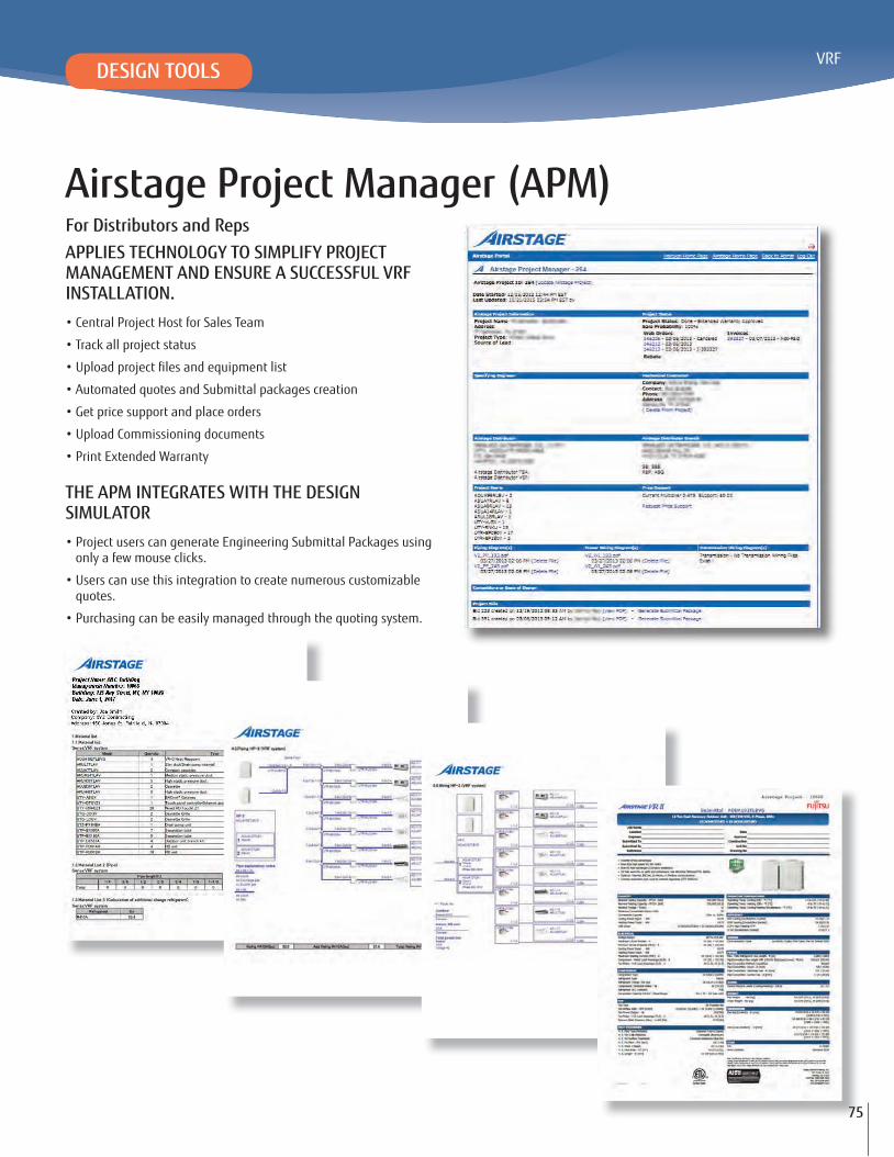
For Distributors and RepsAPPLIES TECHNOLOGY TO SIMPLIFY PROJECT MANAGEMENT AND ENSURE A SUCCESSFUL VRF INSTALLATION.• Central Project Host for Sales Team
• Track all project status
• Automated quotes and Submittal packages creation
• Get price support and place orders
• Upload Commissioning documents
• Print Extended Warranty
THE APM INTEGRATES WITH THE DESIGN SIMULATOR• Project users can generate Engineering Submittal Packages using
only a few mouse clicks.
• Users can use this integration to create numerous customizable quotes.
• Purchasing can be easily managed through the quoting system.
DESIGN TOOLS
75

76
Resources
Airstage Website (for building owners)
http://www.airstagevrf.com
A PLACE TO LEARN THE BASICSGo to airstagevrf.com to learn more about Fujitsu’s Airstage VRF products and programs such as:
Airstage Portal (for Engineers and Contractors)
https://portal.fujitsugeneral.com
A CENTRAL PLACE FOR PROJECT MEMBERS TO COORDINATEThe Airstage Portal provides a single source for all information for Fujitsu Airstage VRF Systems. From the Airstage Portal, all registered users have access to a wealth of information including manuals, technical information, diagrams, online training and more.
Who has access to the Portal?
• Engineers
• Contractors
• Fujitsu Distributors/Personnel
• Independent Airstage Sales Reps
To create a Portal account, go to http://portal.fujitsugeneral.com and click on “Register Now”.
AIRSTAGE PROJECT MANAGER (APM) ON THE FUJITSU PORTAL (for Reps and Distributors)
A PLACE TO SUPPORT PROJECTS ALL THE WAY TO COMPLETION
The APM ensures clear and effective communication between all members of the Fujitsu channel by applying technology to simplify project management and ensure a successful VRF installation. For access to the APM, contact your Airstage Rep. Here’s what you can do inside the APM:
• Manage your Fujitsu Airstage projects large and small.
• Create a project and track its progress from the design stage, to quote generation, order processing and deliverytracking to submittal and commissioning.
• Import equipment schedules from the Fujitsu Design
• Simulator as well as piping and wiring diagrams.
• Request and manage job pricing.
• Basic Product Overview
•
• Service & Support
• Locate a Contractor Distributor
• Contact Us
• Portal Login
• Case Studies
• Locate a Sales Rep