control tips - content.interlinebrands.com tips a robertshaw® ... 5500 series universal infinite...
TRANSCRIPT

C O N T R O L T I P S AROBERTSHAW®INFORMATIONALGUIDE
INFINITE CONTROL SWITCHESBACKGROUND – OPERATION – TROUBLESHOOTING
T H I S I S S U E
1
The Robertshaw® Controls Company hasmanufactured over 250,000,000 infinite controls. These switches are used widely for top burners on electric ranges. Because of their unique design, they have also been used in a variety of other applications and manufactured in many voltages, mounting and dial stem variations.Infinite switch controls and the 5500 Series Universal Infinite Uni-Kits are distributed for easy replacement of original equipment infinite controls. In addition, many brand specific Uni-Kits are available for replacement application needs.5500 Series Universal Infinite Uni-Kits include adapters for screw or palnut type mounting. Uni-Kitsare available with white dials, black dials or no dial and include a variety of dial adapters to allow the original equipment dial to be used. Uni-Kits have a patented, factory assembled dial shaft with easy break off grooves which can be snapped off to match various shaft lengths. Models are rated 15 amps at 120V AC, 208V AC and 240V AC resistive load. Infinite switches should not be applied where the ambient temperatures exceed 180°F. Complete specification, ordering information and cross reference data can be located in the Uni-Line Catalog. The Uni-Line Catalog is available online at www.invensyscontrols.com or you can obtain a printed copy from Sales or Customer Service. Installation instructions with a variety of wiring diagrams (including replacement of other brand infinite switches) are included with each Uni-Kit.
How the Model INF Infinite Control OperatesThe dial shaft of the Model INF turns clockwise or counterclockwise. It is equipped with three positive indexing positions: Hi-Off-Lo. In the Hi position, the Model INF control is energized continuously. At other settings it delivers the selected level of input under the control of a bimetal timer. A double-line disconnect is provided when the INF control is in the Off position. If the shaft does not turn easily, press down slightly on the knob as some Model INF controls include a Push-to-Turn safety feature. The permanent magnet provides for a snap action of the contacts (see diagram on page 2).The Model INF control contains a bimetal which regulates the running cycles. This bimetal has a resis-tance wire wrapped around it which is connected in parallel with the heating unit being controlled and is cycled in unison with the heating element. When the dial is turned to any On position, the cam follower moves out and allows the cycling contacts to close. This completes a circuit through the heating unit
5500-204 Uni-Kit
2
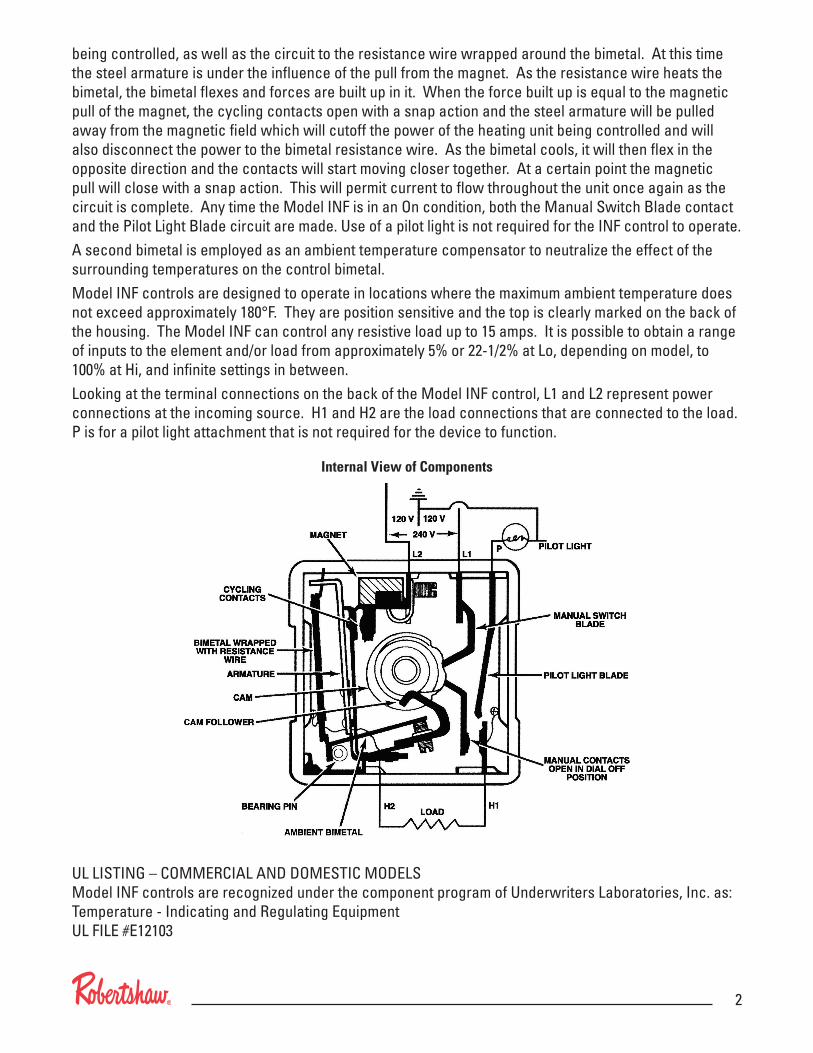
being controlled, as well as the circuit to the resistance wire wrapped around the bimetal. At this time the steel armature is under the influence of the pull from the magnet. As the resistance wire heats the bimetal, the bimetal flexes and forces are built up in it. When the force built up is equal to the magnetic pull of the magnet, the cycling contacts open with a snap action and the steel armature will be pulled away from the magnetic field which will cutoff the power of the heating unit being controlled and will also disconnect the power to the bimetal resistance wire. As the bimetal cools, it will then flex in the opposite direction and the contacts will start moving closer together. At a certain point the magnetic pull will close with a snap action. This will permit current to flow throughout the unit once again as the circuit is complete. Any time the Model INF is in an On condition, both the Manual Switch Blade contact and the Pilot Light Blade circuit are made. Use of a pilot light is not required for the INF control to operate.A second bimetal is employed as an ambient temperature compensator to neutralize the effect of the surrounding temperatures on the control bimetal.Model INF controls are designed to operate in locations where the maximum ambient temperature does not exceed approximately 180°F. They are position sensitive and the top is clearly marked on the back of the housing. The Model INF can control any resistive load up to 15 amps. It is possible to obtain a range of inputs to the element and/or load from approximately 5% or 22-1/2% at Lo, depending on model, to 100% at Hi, and infinite settings in between.Looking at the terminal connections on the back of the Model INF control, L1 and L2 represent power connections at the incoming source. H1 and H2 are the load connections that are connected to the load. P is for a pilot light attachment that is not required for the device to function.
Internal View of Components
UL LISTING – COMMERCIAL AND DOMESTIC MODELS Model INF controls are recognized under the component program of Underwriters Laboratories, Inc. as: Temperature - Indicating and Regulating Equipment UL FILE #E12103
3
Troubleshooting Model INF Infinite ControlsCAUTION: This device should be installed and tested by a qualified service technician with due regard for safety and code requirements. High electrical voltages may be present during testing and care should be exercised.
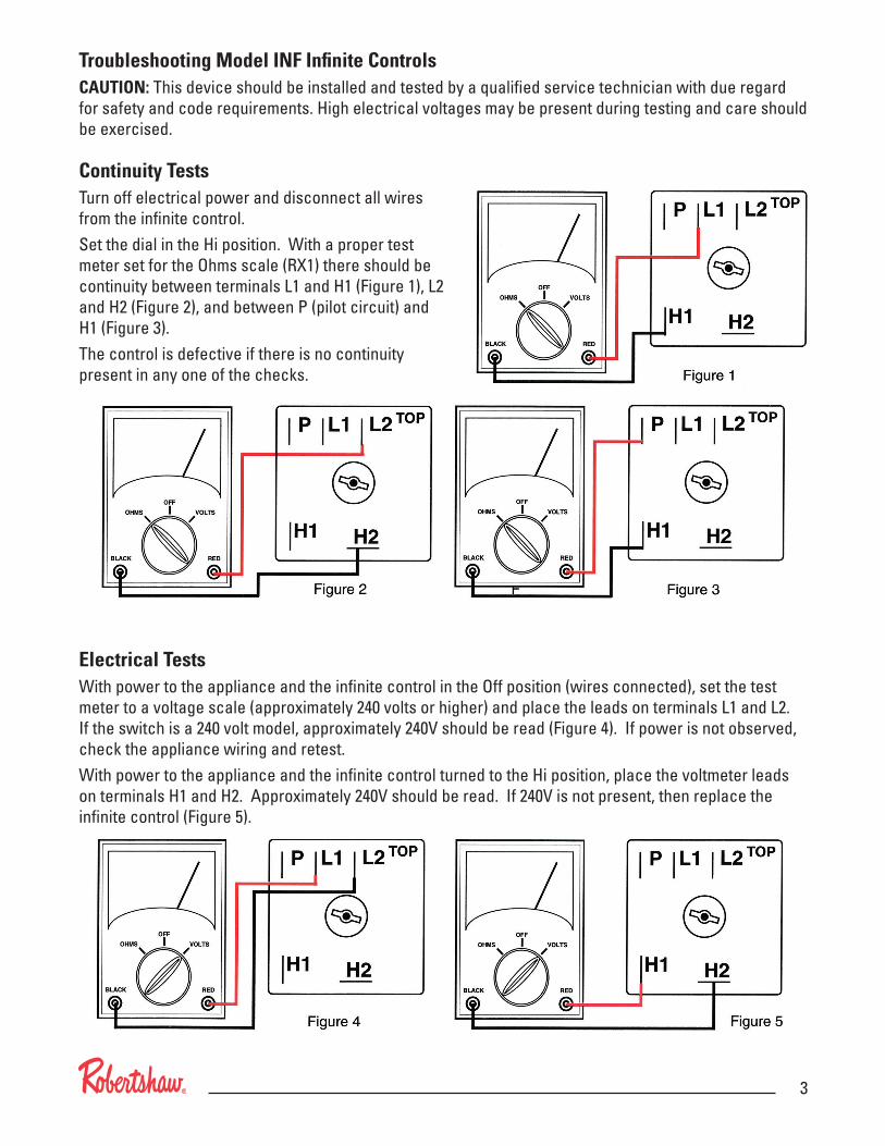
Continuity TestsTurn off electrical power and disconnect all wires from the infinite control.Set the dial in the Hi position. With a proper test meter set for the Ohms scale (RX1) there should be continuity between terminals L1 and H1 (Figure 1), L2 and H2 (Figure 2), and between P (pilot circuit) and H1 (Figure 3).The control is defective if there is no continuity present in any one of the checks.
Electrical TestsWith power to the appliance and the infinite control in the Off position (wires connected), set the test meter to a voltage scale (approximately 240 volts or higher) and place the leads on terminals L1 and L2. If the switch is a 240 volt model, approximately 240V should be read (Figure 4). If power is not observed, check the appliance wiring and retest.With power to the appliance and the infinite control turned to the Hi position, place the voltmeter leads on terminals H1 and H2. Approximately 240V should be read. If 240V is not present, then replace the infinite control (Figure 5).
191 E. North AvenueCarol Stream Illinois 60188 USACustomer Service Telephone 1.800.304.6563Customer Service Facsimile [email protected]
For Technical ServiceTelephone 1.800.445.8299Facsimile [email protected] 11/10 – 150-2160B
www.Uni-Line.comwww.InvensysControls.com©2010 Invensys Controls
Consult the Uni-Line®
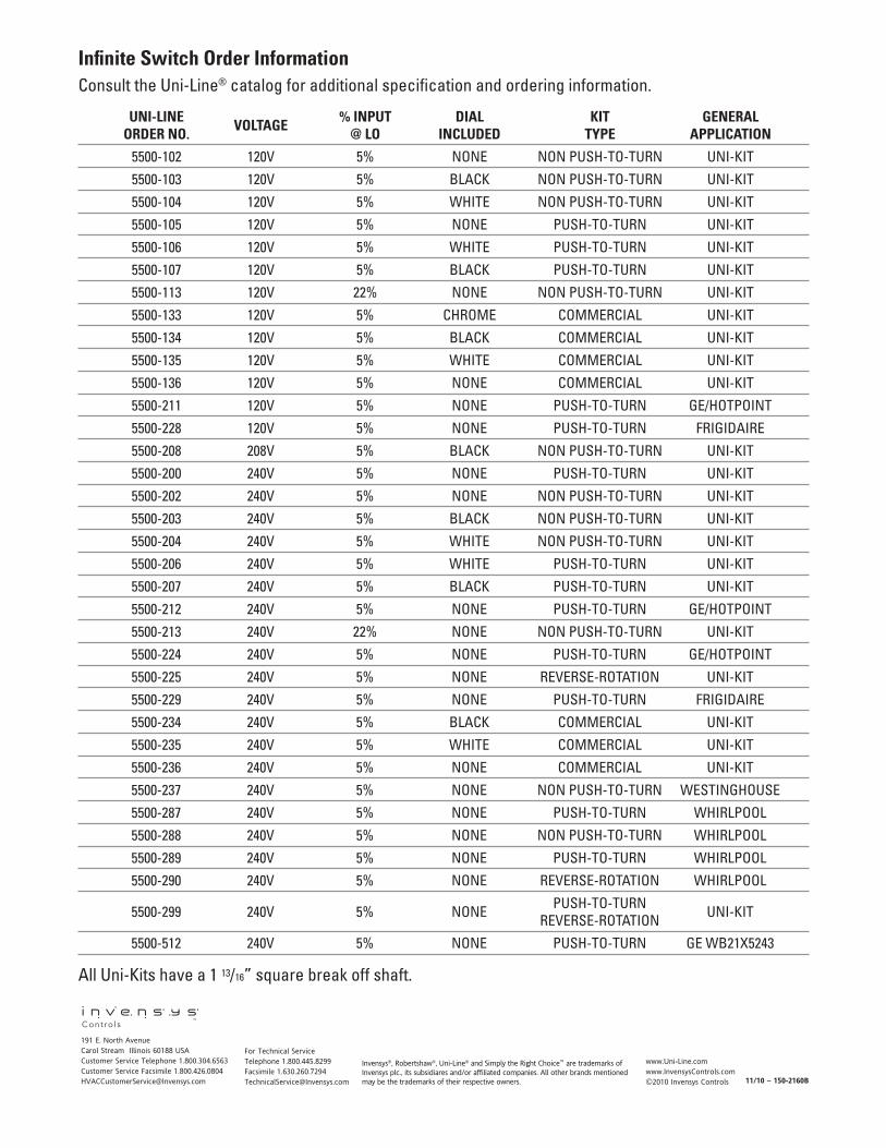
UNI-LINE VOLTAGE % INPUT DIAL KIT GENERAL ORDER NO. @ LO INCLUDED TYPE APPLICATION
5500-102 120V 5% NONE NON PUSH-TO-TURN UNI-KIT
5500-103 120V 5% BLACK NON PUSH-TO-TURN UNI-KIT
5500-104 120V 5% WHITE NON PUSH-TO-TURN UNI-KIT
5500-105 120V 5% NONE PUSH-TO-TURN UNI-KIT
5500-106 120V 5% WHITE PUSH-TO-TURN UNI-KIT
5500-107 120V 5% BLACK PUSH-TO-TURN UNI-KIT
5500-113 120V 22% NONE NON PUSH-TO-TURN UNI-KIT
5500-133 120V 5% CHROME COMMERCIAL UNI-KIT
5500-134 120V 5% BLACK COMMERCIAL UNI-KIT
5500-135 120V 5% WHITE COMMERCIAL UNI-KIT
5500-136 120V 5% NONE COMMERCIAL UNI-KIT
5500-211 120V 5% NONE PUSH-TO-TURN GE/HOTPOINT
5500-228 120V 5% NONE PUSH-TO-TURN FRIGIDAIRE
5500-208 208V 5% BLACK NON PUSH-TO-TURN UNI-KIT
5500-200 240V 5% NONE PUSH-TO-TURN UNI-KIT
5500-202 240V 5% NONE NON PUSH-TO-TURN UNI-KIT
5500-203 240V 5% BLACK NON PUSH-TO-TURN UNI-KIT
5500-204 240V 5% WHITE NON PUSH-TO-TURN UNI-KIT
5500-206 240V 5% WHITE PUSH-TO-TURN UNI-KIT
5500-207 240V 5% BLACK PUSH-TO-TURN UNI-KIT
5500-212 240V 5% NONE PUSH-TO-TURN GE/HOTPOINT
5500-213 240V 22% NONE NON PUSH-TO-TURN UNI-KIT
5500-224 240V 5% NONE PUSH-TO-TURN GE/HOTPOINT
5500-225 240V 5% NONE REVERSE-ROTATION UNI-KIT
5500-229 240V 5% NONE PUSH-TO-TURN FRIGIDAIRE
5500-234 240V 5% BLACK COMMERCIAL UNI-KIT
5500-235 240V 5% WHITE COMMERCIAL UNI-KIT
5500-236 240V 5% NONE COMMERCIAL UNI-KIT
5500-237 240V 5% NONE NON PUSH-TO-TURN WESTINGHOUSE
5500-287 240V 5% NONE PUSH-TO-TURN WHIRLPOOL
5500-288 240V 5% NONE NON PUSH-TO-TURN WHIRLPOOL
5500-289 240V 5% NONE PUSH-TO-TURN WHIRLPOOL
5500-290 240V 5% NONE REVERSE-ROTATION WHIRLPOOL
5500-299 240V 5% NONE PUSH-TO-TURN UNI-KIT REVERSE-ROTATION
5500-512 240V 5% NONE PUSH-TO-TURN GE WB21X5243
All Uni-Kits have a 1 13/16” square break off shaft.
Invensys®, Robertshaw®, Uni-Line® and Simply the Right Choice™ are trademarks of Invensys plc., its subsidiares and/or affiliated companies. All other brands mentioned may be the trademarks of their respective owners.