control using two manipulated parametersmodelingandcontrol.com/repository/twomanipcontrol.pdf ·...
TRANSCRIPT
©2006Fisher-Rosemount Systems, Inc.Slide 1- 1
Control Using Two Manipulated Parameters
Control Using Two Control Using Two Manipulated Parameters Manipulated Parameters
©2006Fisher-Rosemount Systems, Inc.Slide 1- 2
Process Control Introduction – Historic Perspective
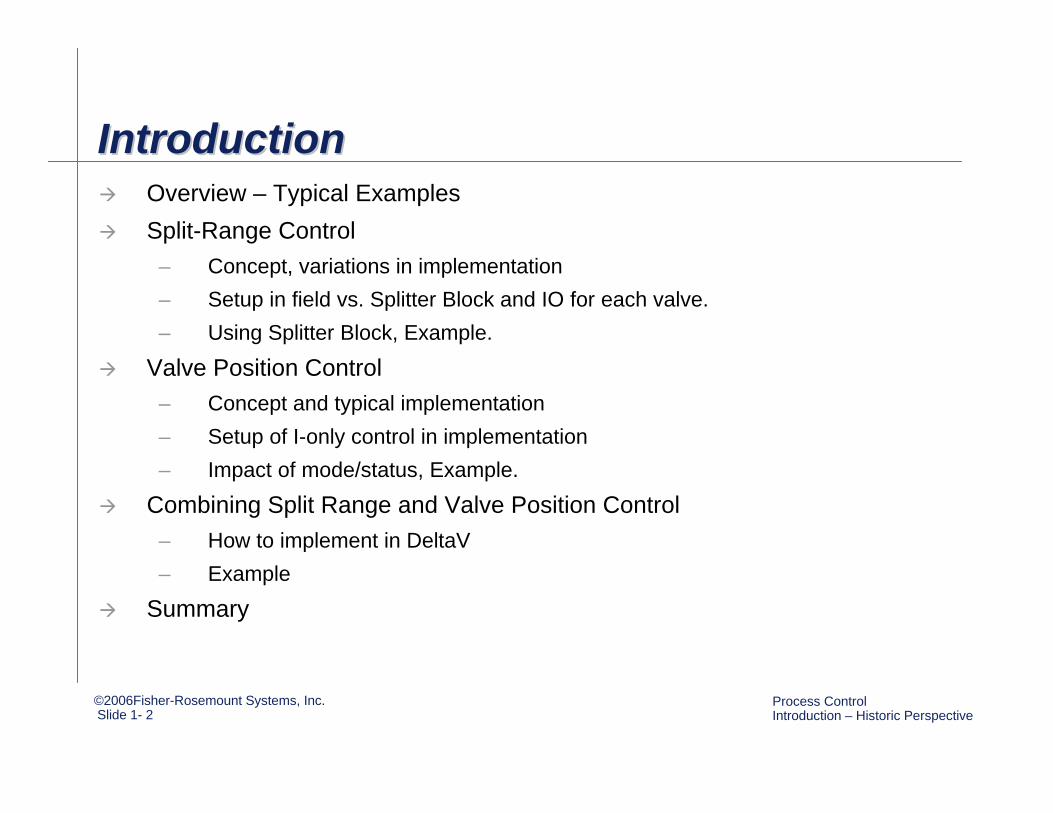
IntroductionIntroductionOverview – Typical ExamplesSplit-Range Control
– Concept, variations in implementation– Setup in field vs. Splitter Block and IO for each valve. – Using Splitter Block, Example.
Valve Position Control– Concept and typical implementation– Setup of I-only control in implementation – Impact of mode/status, Example.
Combining Split Range and Valve Position Control– How to implement in DeltaV– Example
Summary
©2006Fisher-Rosemount Systems, Inc.Slide 1- 3
Process Control Introduction – Historic Perspective
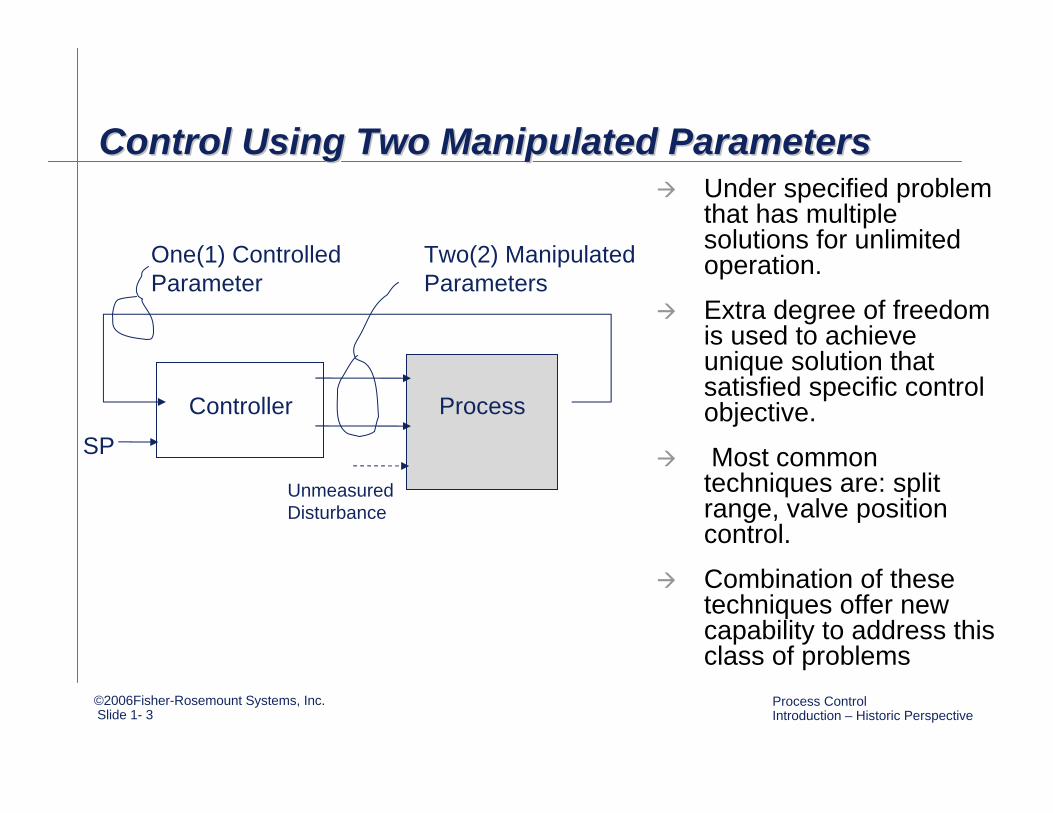
Control Using Two Manipulated ParametersControl Using Two Manipulated ParametersControl Using Two Manipulated ParametersUnder specified problem that has multiple solutions for unlimited operation.
Extra degree of freedom is used to achieve unique solution that satisfied specific control objective.
Most common techniques are: split range, valve position control.
Combination of these techniques offer new capability to address this class of problems
Controller Process
SP
Unmeasured Disturbance
One(1) Controlled Parameter
Two(2) Manipulated Parameters
©2006Fisher-Rosemount Systems, Inc.Slide 1- 4
Process Control Introduction – Historic Perspective
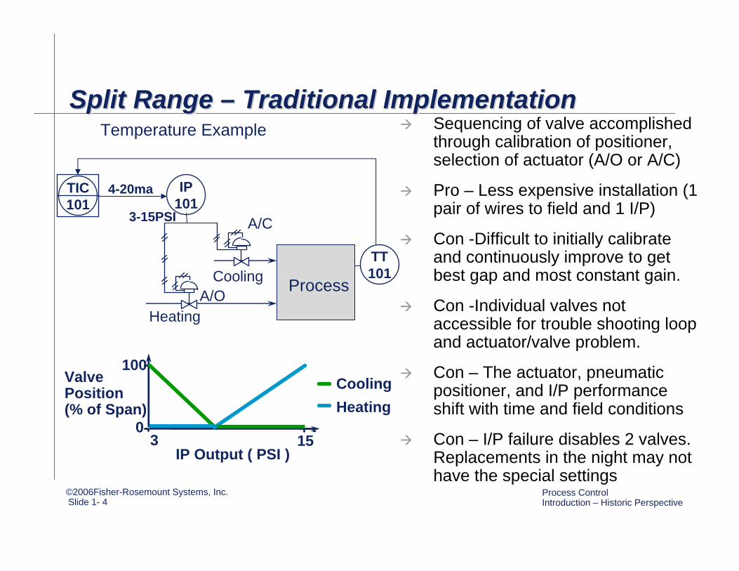
Split Range – Traditional Implementation Split Range Split Range –– Traditional Implementation Traditional Implementation Sequencing of valve accomplished through calibration of positioner, selection of actuator (A/O or A/C)
Pro – Less expensive installation (1 pair of wires to field and 1 I/P)
Con -Difficult to initially calibrate and continuously improve to get best gap and most constant gain.
Con -Individual valves not accessible for trouble shooting loop and actuator/valve problem.
Con – The actuator, pneumatic positioner, and I/P performance shift with time and field conditions
Con – I/P failure disables 2 valves. Replacements in the night may not have the special settings
IP101
TT101
TIC101
Process
Temperature Example
4-20ma
Heating
Cooling
3-15PSI
ValvePosition(% of Span)
IP Output ( PSI )153
0
100Cooling Heating
A/C
A/O
©2006Fisher-Rosemount Systems, Inc.Slide 1- 5
Process Control Introduction – Historic Perspective
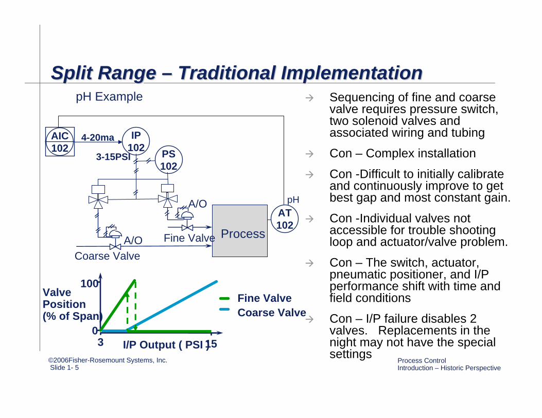
Split Range – Traditional ImplementationSplit Range Split Range –– Traditional ImplementationTraditional ImplementationSequencing of fine and coarse valve requires pressure switch, two solenoid valves and associated wiring and tubing
Con – Complex installation
Con -Difficult to initially calibrate and continuously improve to get best gap and most constant gain.
Con -Individual valves not accessible for trouble shooting loop and actuator/valve problem.
Con – The switch, actuator, pneumatic positioner, and I/P performance shift with time and field conditions
Con – I/P failure disables 2 valves. Replacements in the night may not have the special settings
IP102
AT102
AIC102
Process
pH Example
4-20ma
Coarse ValveFine Valve
3-15PSI
A/O
pH
ValvePosition(% of Span)
I/P Output ( PSI )1530
100Fine ValveCoarse Valve
A/O
PS102
©2006Fisher-Rosemount Systems, Inc.Slide 1- 6
Process Control Introduction – Historic Perspective
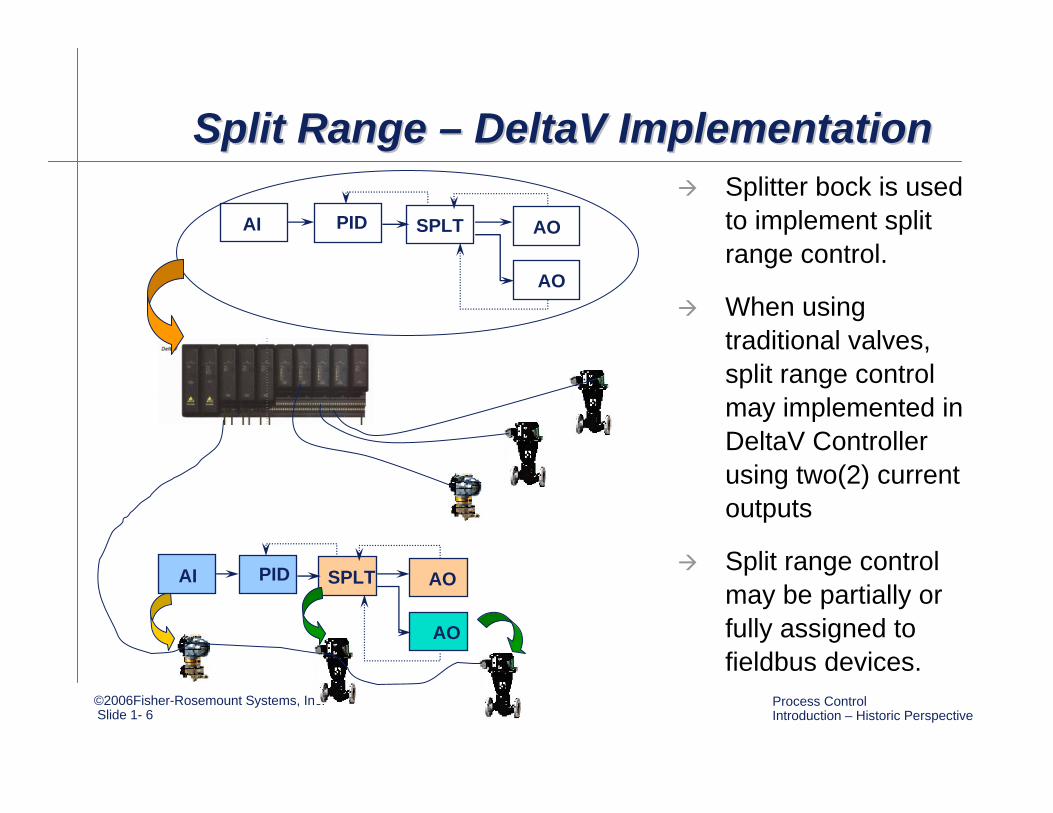
Split Range – DeltaV Implementation Split Range Split Range –– DeltaV Implementation DeltaV Implementation Splitter bock is used to implement split range control.
When using traditional valves, split range control may implemented in DeltaV Controller using two(2) current outputs
Split range control may be partially or fully assigned to fieldbus devices.
AI PID SPLT
AO
AO
AI PID SPLT
AO
AO
©2006Fisher-Rosemount Systems, Inc.Slide 1- 7
Process Control Introduction – Historic Perspective
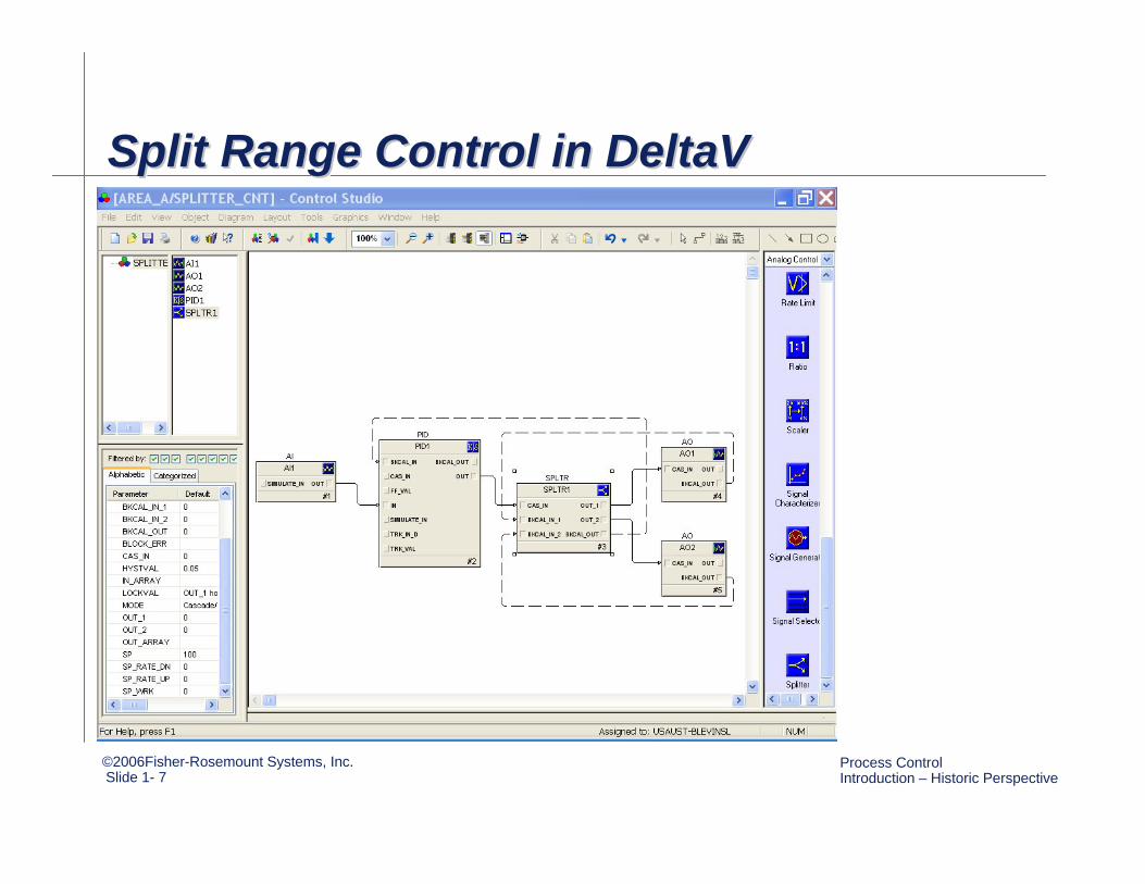
Split Range Control in DeltaVSplit Range Control in DeltaVSplit Range Control in DeltaV
©2006Fisher-Rosemount Systems, Inc.Slide 1- 8
Process Control Introduction – Historic Perspective
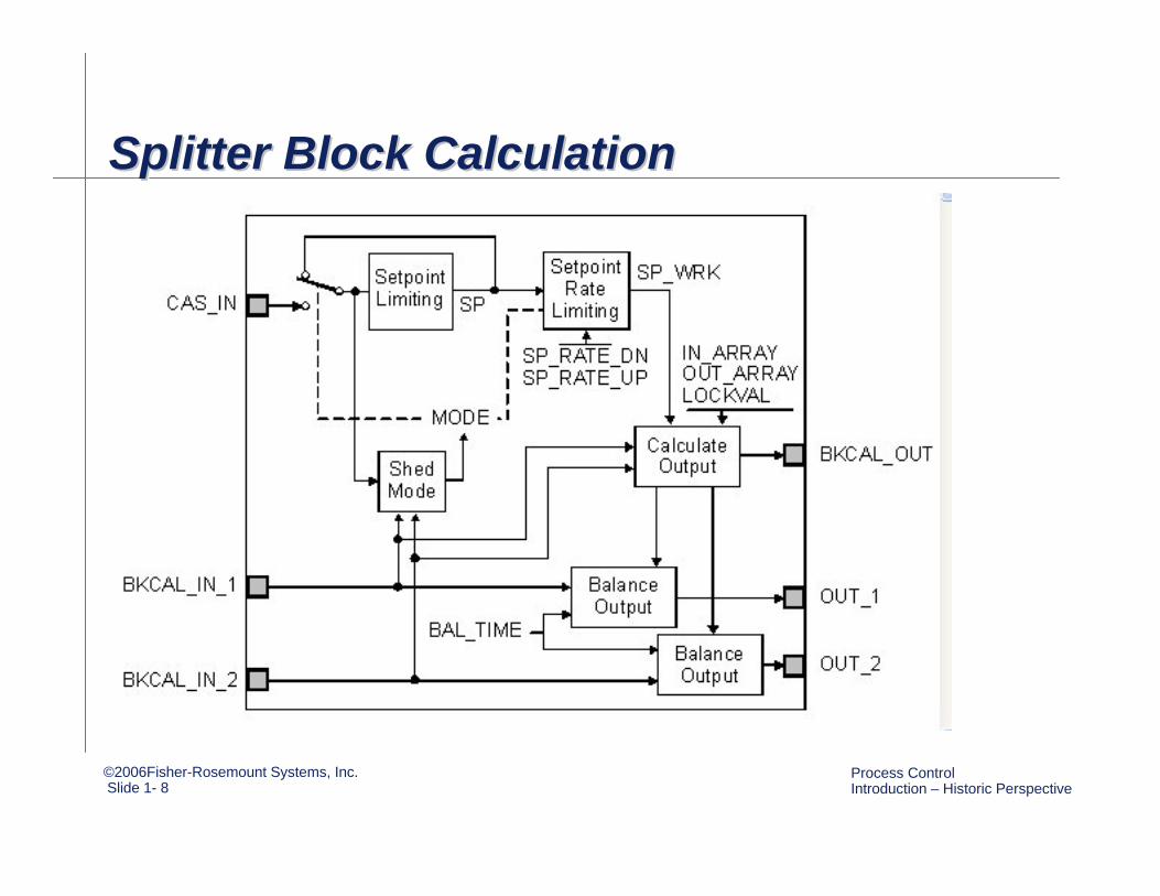
Splitter Block CalculationSplitter Block CalculationSplitter Block Calculation
©2006Fisher-Rosemount Systems, Inc.Slide 1- 9
Process Control Introduction – Historic Perspective
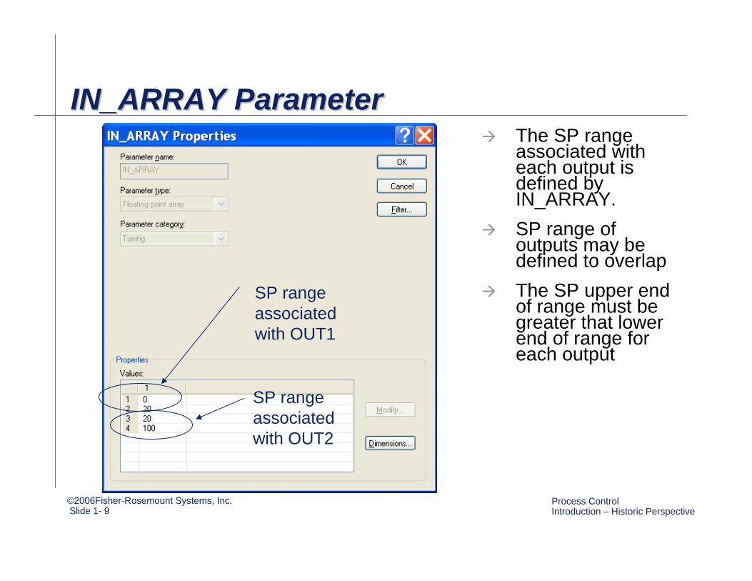
IN_ARRAY ParameterIN_ARRAY ParameterIN_ARRAY ParameterThe SP range associated with each output is defined by IN_ARRAY. SP range of outputs may be defined to overlapThe SP upper end of range must be greater that lower end of range for each output
SP range associated with OUT1
SP range associated with OUT2
©2006Fisher-Rosemount Systems, Inc.Slide 1- 10
Process Control Introduction – Historic Perspective
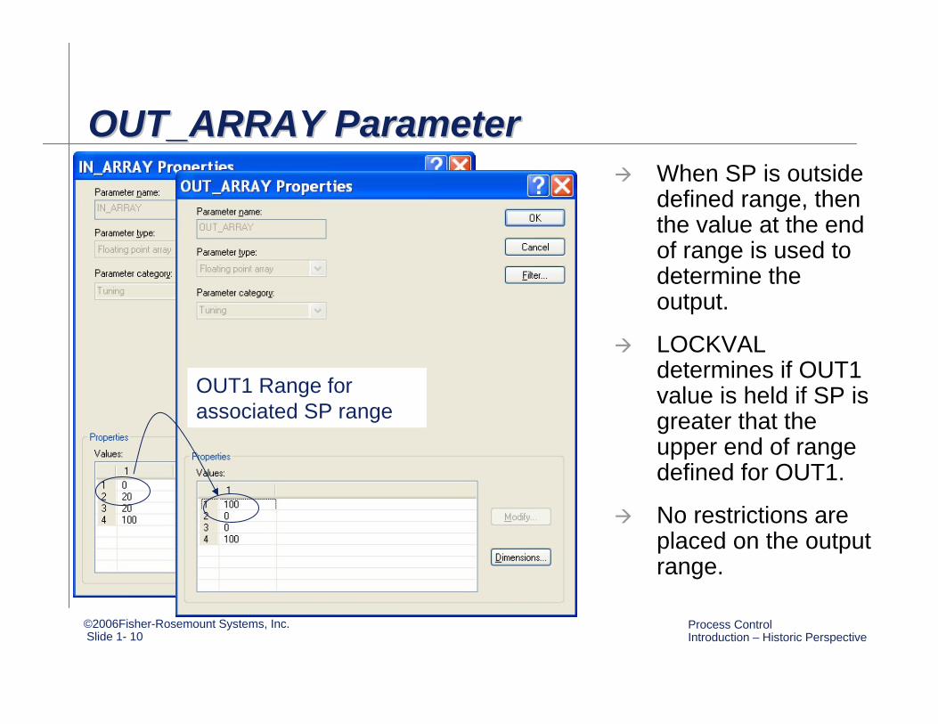
OUT_ARRAY ParameterOUT_ARRAY ParameterOUT_ARRAY ParameterWhen SP is outside defined range, then the value at the end of range is used to determine the output.
LOCKVAL determines if OUT1 value is held if SP is greater that the upper end of range defined for OUT1.
No restrictions are placed on the output range.
OUT1 Range for associated SP range
©2006Fisher-Rosemount Systems, Inc.Slide 1- 11
Process Control Introduction – Historic Perspective
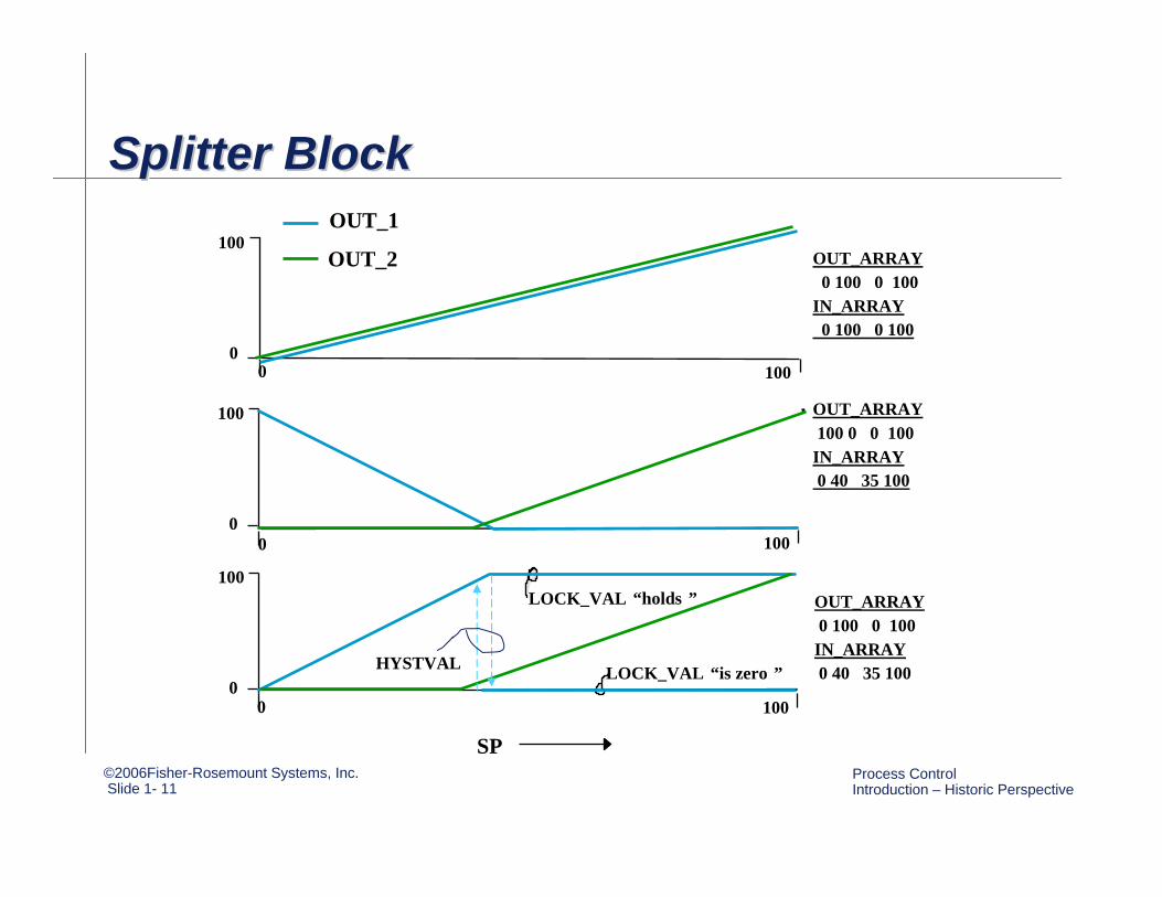
Splitter BlockSplitter BlockSplitter Block
SP
0 1000
100
0
100
0
100
100
100
0
0
OUT_1
OUT_2
LOCK_VAL “holds ”
LOCK_VAL “is zero ”
OUT_ARRAY0 100 0 100
IN_ARRAY0 100 0 100
OUT_ARRAY100 0 0 100IN_ARRAY0 40 35 100
OUT_ARRAY0 100 0 100IN_ARRAY0 40 35 100HYSTVAL
©2006Fisher-Rosemount Systems, Inc.Slide 1- 12
Process Control Introduction – Historic Perspective
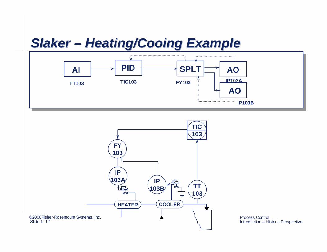
AI PID SPLT
AO
AO
IP103A IP
103B TT103
FY103
TIC103
COOLERHEATER
TT103 TIC103 FY103 IP103A
IP103B
Slaker – Heating/Cooing ExampleSlakerSlaker –– Heating/Cooing ExampleHeating/Cooing Example
©2006Fisher-Rosemount Systems, Inc.Slide 1- 13
Process Control Introduction – Historic Perspective
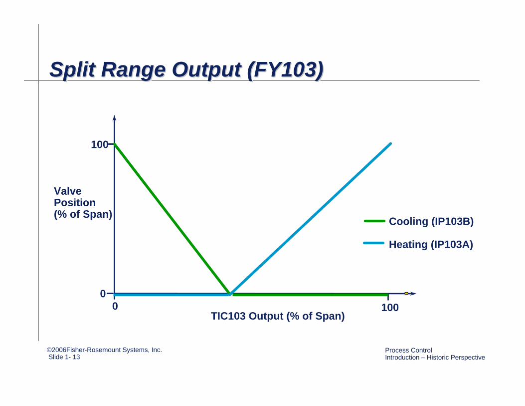
ValvePosition(% of Span)
TIC103 Output (% of Span)1000
0
100
Cooling (IP103B)
Heating (IP103A)
Split Range Output (FY103)Split Range Output (FY103)Split Range Output (FY103)
©2006Fisher-Rosemount Systems, Inc.Slide 1- 14
Process Control Introduction – Historic Perspective
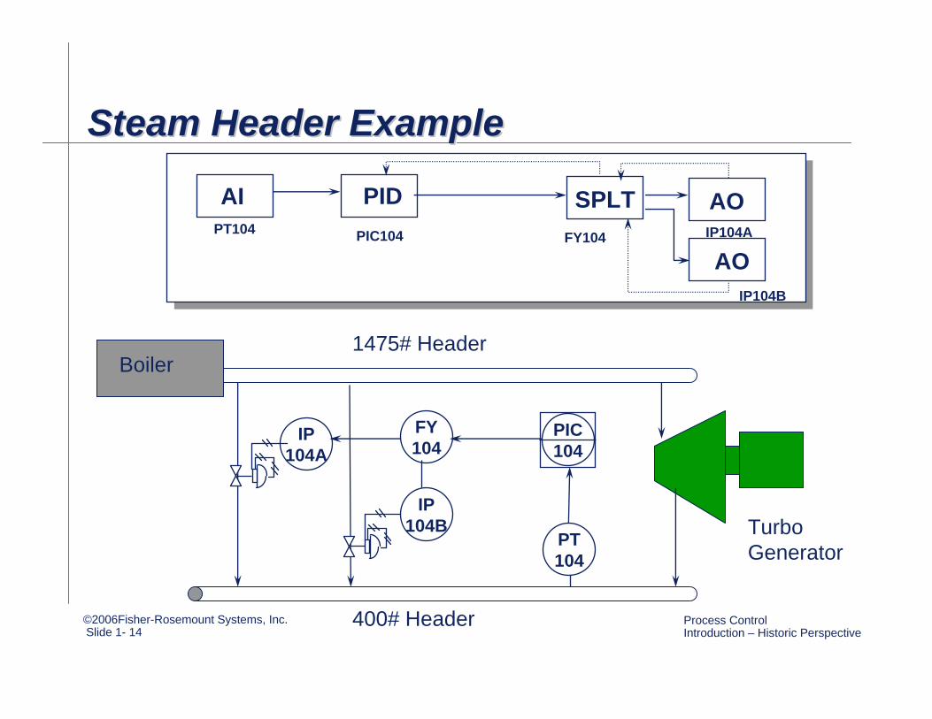
AI PID SPLT
AO
AO
IP104A
IP104B
PT104
FY104
PIC104
PT104 PIC104 FY104 IP104A
IP104B
Steam Header ExampleSteam Header ExampleSteam Header Example
400# Header
1475# HeaderBoiler
Turbo Generator
©2006Fisher-Rosemount Systems, Inc.Slide 1- 15
Process Control Introduction – Historic Perspective
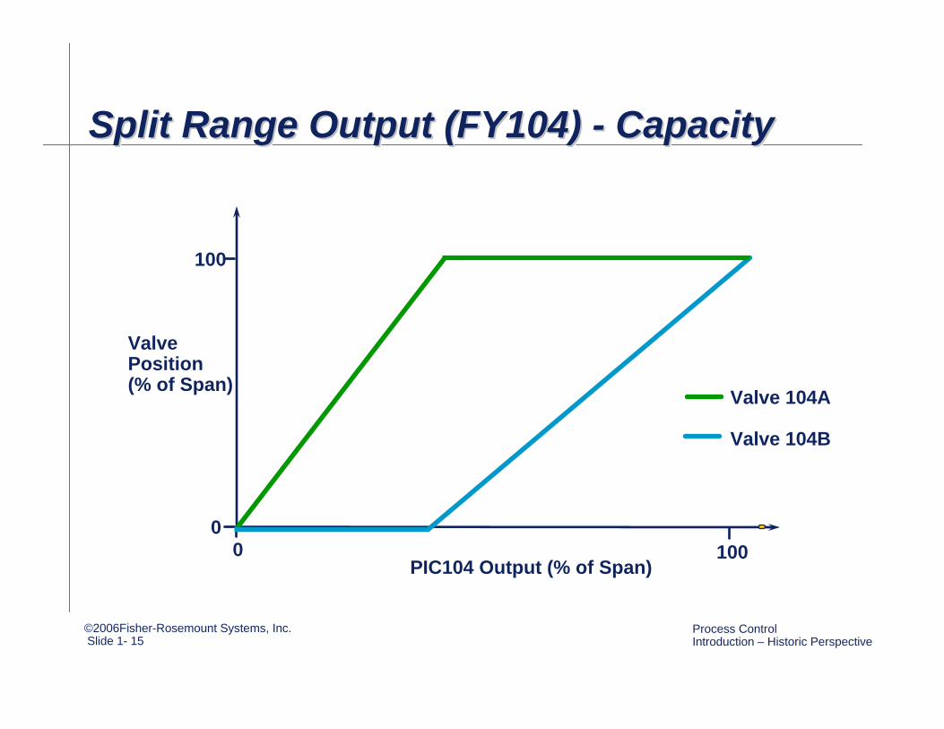
ValvePosition(% of Span)
PIC104 Output (% of Span)1000
0
100
Valve 104A
Valve 104B
Split Range Output (FY104) - CapacitySplit Range Output (FY104) Split Range Output (FY104) -- CapacityCapacity
©2006Fisher-Rosemount Systems, Inc.Slide 1- 16
Process Control Introduction – Historic Perspective
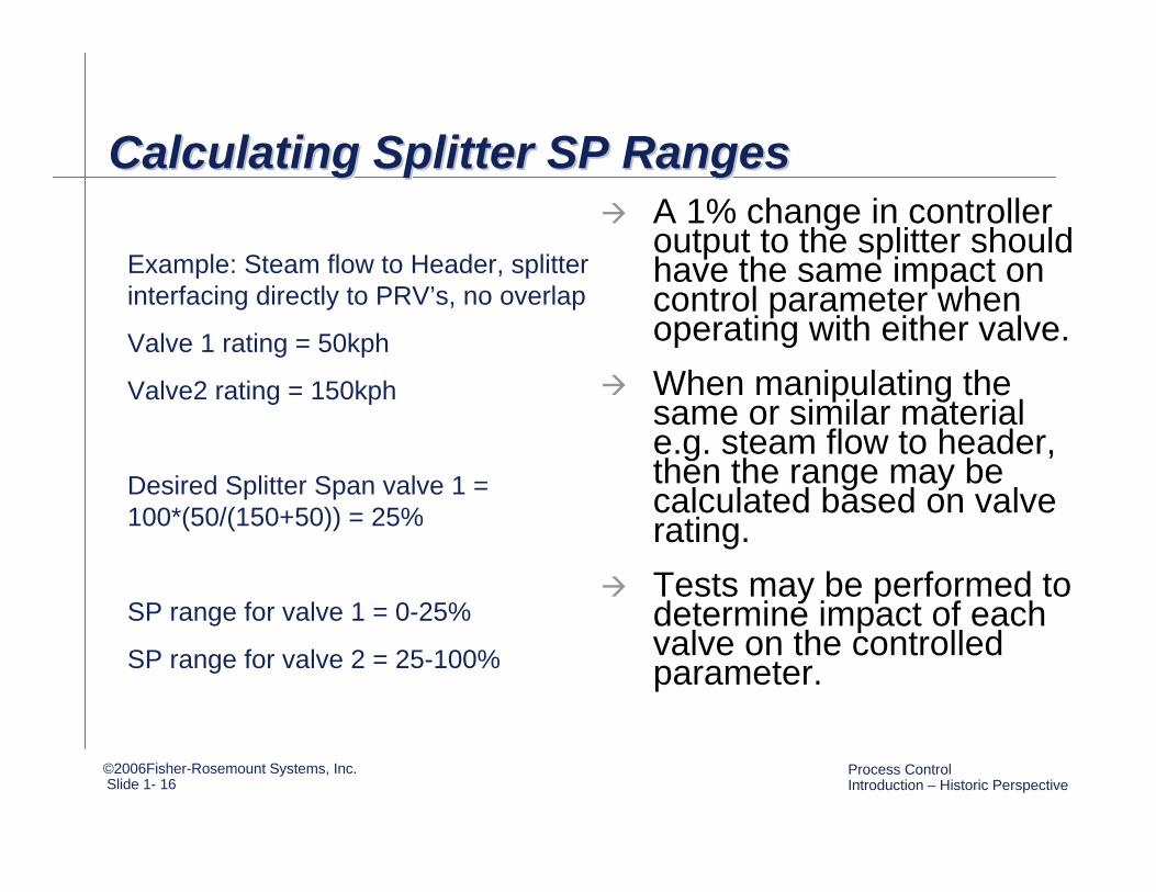
Calculating Splitter SP RangesCalculating Splitter SP RangesCalculating Splitter SP RangesA 1% change in controller output to the splitter should have the same impact on control parameter when operating with either valve.When manipulating the same or similar material e.g. steam flow to header, then the range may be calculated based on valve rating. Tests may be performed to determine impact of each valve on the controlled parameter.
Example: Steam flow to Header, splitter interfacing directly to PRV’s, no overlap
Valve 1 rating = 50kph
Valve2 rating = 150kph
Desired Splitter Span valve 1 = 100*(50/(150+50)) = 25%
SP range for valve 1 = 0-25%
SP range for valve 2 = 25-100%
©2006Fisher-Rosemount Systems, Inc.Slide 1- 17
Process Control Introduction – Historic Perspective
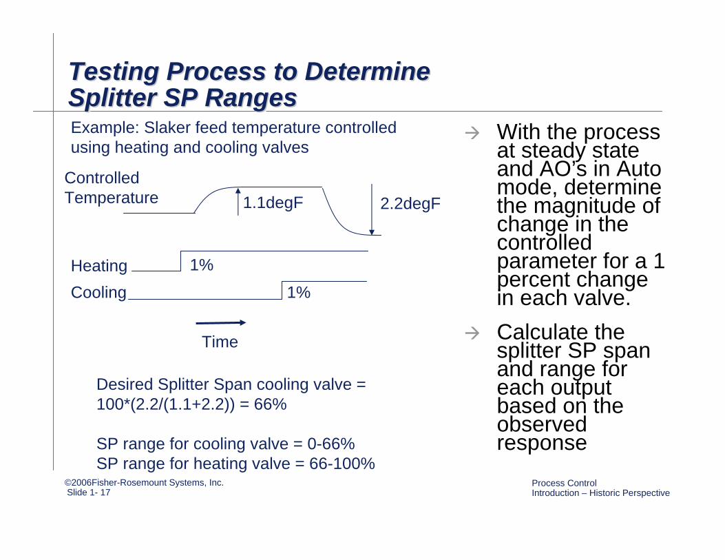
Testing Process to Determine Splitter SP RangesTesting Process to Determine Testing Process to Determine Splitter SP RangesSplitter SP Ranges
With the process at steady state and AO’s in Auto mode, determine the magnitude of change in the controlled parameter for a 1 percent change in each valve.Calculate the splitter SP span and range for each output based on the observed response
Time
CoolingHeating 1%
1%
1.1degF 2.2degF
Desired Splitter Span cooling valve = 100*(2.2/(1.1+2.2)) = 66%
SP range for cooling valve = 0-66%SP range for heating valve = 66-100%
Controlled Temperature
Example: Slaker feed temperature controlled using heating and cooling valves
©2006Fisher-Rosemount Systems, Inc.Slide 1- 18
Process Control Introduction – Historic Perspective
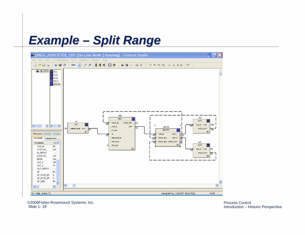
Example – Split RangeExample Example –– Split RangeSplit Range
©2006Fisher-Rosemount Systems, Inc.Slide 1- 19
Process Control Introduction – Historic Perspective
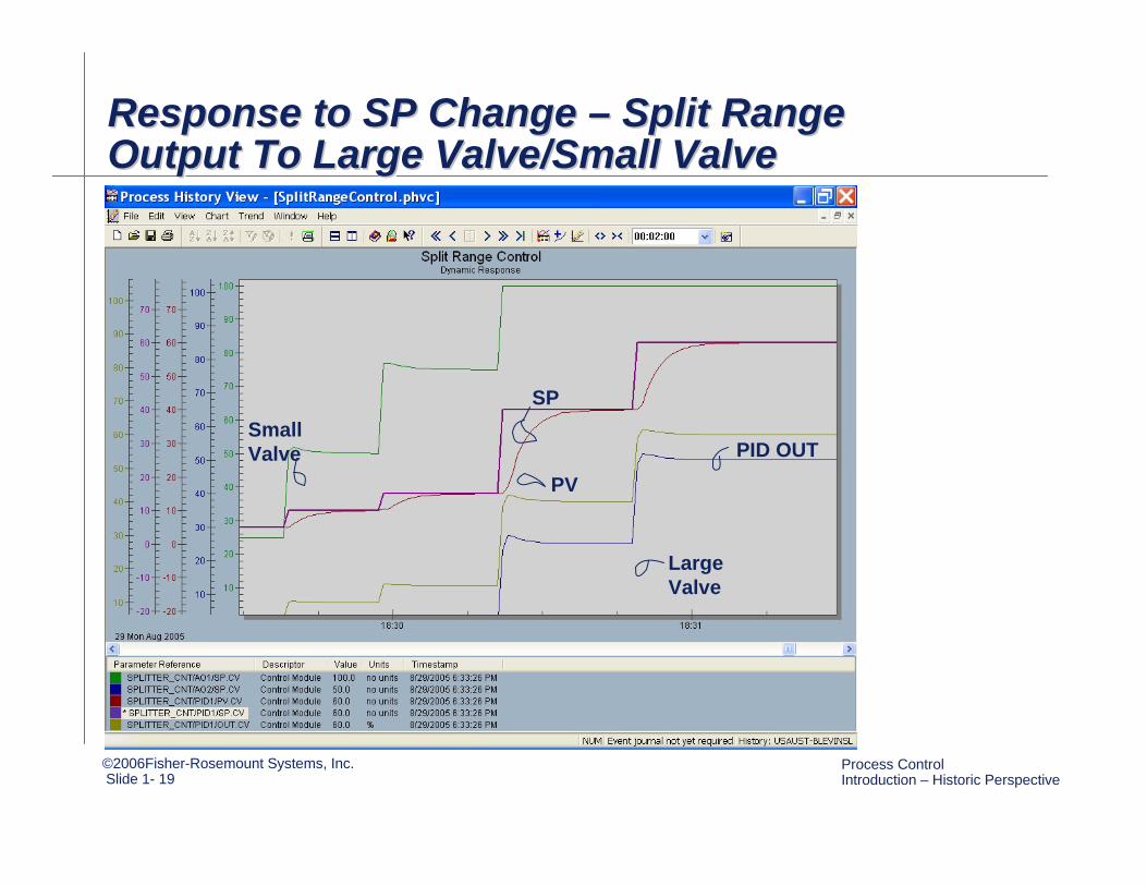
Response to SP Change – Split Range Output To Large Valve/Small ValveResponse to SP Change Response to SP Change –– Split Range Split Range Output To Large Valve/Small ValveOutput To Large Valve/Small Valve
Small Valve
Large Valve
PID OUT
SP
PV
©2006Fisher-Rosemount Systems, Inc.Slide 1- 20
Process Control Introduction – Historic Perspective
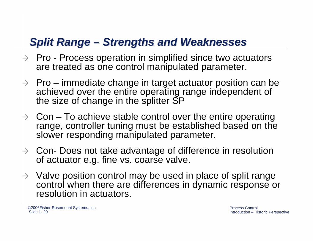
Split Range – Strengths and WeaknessesSplit Range Split Range –– Strengths and WeaknessesStrengths and WeaknessesPro - Process operation in simplified since two actuators are treated as one control manipulated parameter.
Pro – immediate change in target actuator position can be achieved over the entire operating range independent of the size of change in the splitter SP
Con – To achieve stable control over the entire operating range, controller tuning must be established based on the slower responding manipulated parameter.
Con- Does not take advantage of difference in resolution of actuator e.g. fine vs. coarse valve.
Valve position control may be used in place of split range control when there are differences in dynamic response or resolution in actuators.
©2006Fisher-Rosemount Systems, Inc.Slide 1- 21
Process Control Introduction – Historic Perspective
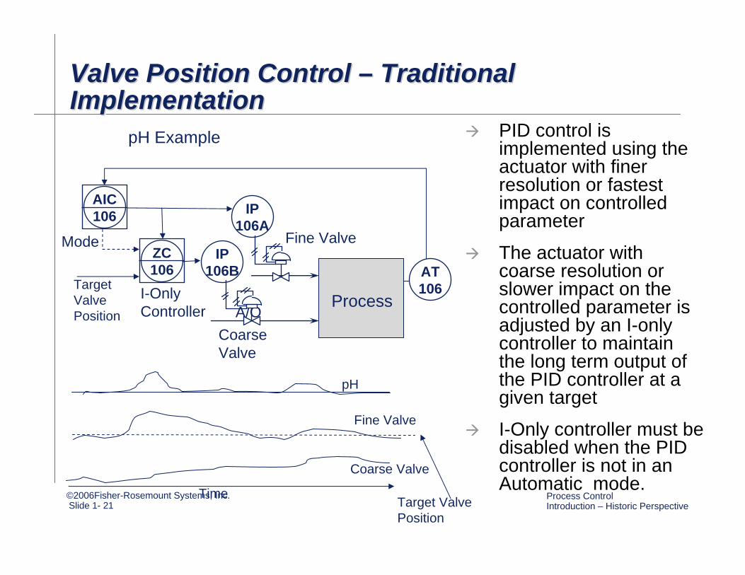
Valve Position Control – Traditional Implementation Valve Position Control Valve Position Control –– Traditional Traditional Implementation Implementation
IP106A
AT106
AIC106
Process
PID control is implemented using the actuator with finer resolution or fastest impact on controlled parameter
The actuator with coarse resolution or slower impact on the controlled parameter is adjusted by an I-only controller to maintain the long term output of the PID controller at a given target
I-Only controller must be disabled when the PID controller is not in an Automatic mode.
pH Example
Fine Valve
A/O
ZC106
IP106B
Coarse Valve
I-Only Controller
Mode
Target Valve Position
Time
pH
Fine Valve
Coarse Valve
Target Valve Position
©2006Fisher-Rosemount Systems, Inc.Slide 1- 22
Process Control Introduction – Historic Perspective
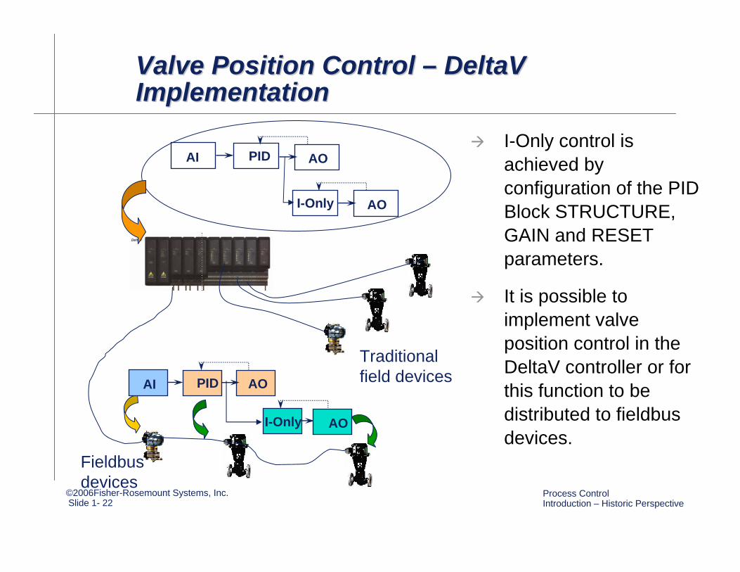
Valve Position Control – DeltaV Implementation Valve Position Control Valve Position Control –– DeltaV DeltaV Implementation Implementation
I-Only control is achieved by configuration of the PID Block STRUCTURE, GAIN and RESET parameters.
It is possible to implement valve position control in the DeltaV controller or for this function to be distributed to fieldbus devices.
AI PID AO
AI PID
AO
AO
I-Only AO
I-Only
Traditional field devices
Fieldbus devices
©2006Fisher-Rosemount Systems, Inc.Slide 1- 23
Process Control Introduction – Historic Perspective
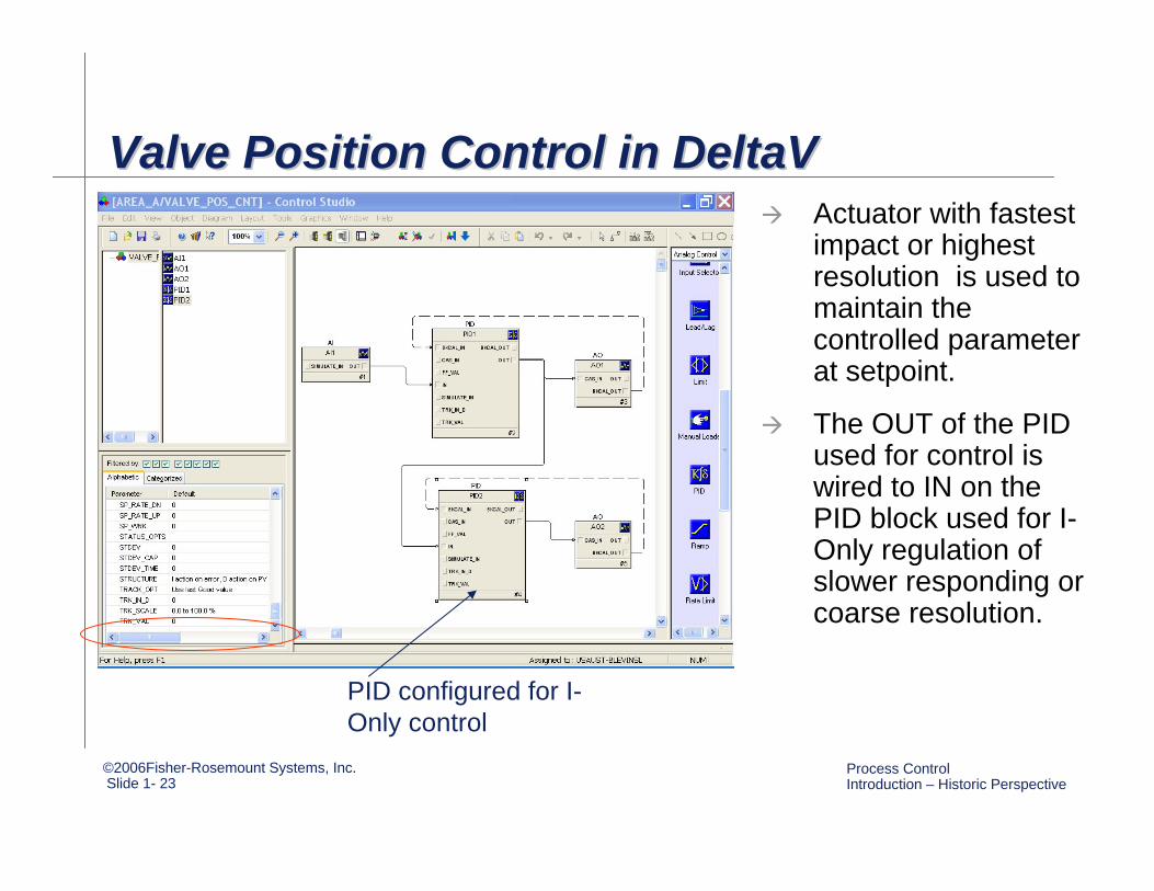
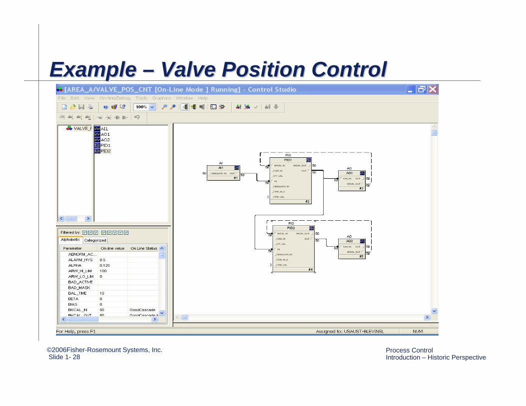
Valve Position Control in DeltaV Valve Position Control in DeltaV Valve Position Control in DeltaV Actuator with fastest impact or highest resolution is used to maintain the controlled parameter at setpoint.
The OUT of the PID used for control is wired to IN on the PID block used for I-Only regulation of slower responding or coarse resolution.
PID configured for I-Only control
©2006Fisher-Rosemount Systems, Inc.Slide 1- 24
Process Control Introduction – Historic Perspective
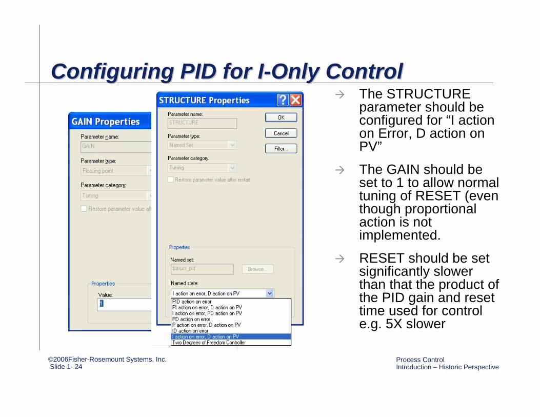
Configuring PID for I-Only ControlConfiguring PID for IConfiguring PID for I--Only ControlOnly ControlThe STRUCTURE parameter should be configured for “I action on Error, D action on PV”
The GAIN should be set to 1 to allow normal tuning of RESET (even though proportional action is not implemented.
RESET should be set significantly slower than that the product of the PID gain and reset time used for control e.g. 5X slower

©2006Fisher-Rosemount Systems, Inc.Slide 1- 25
Process Control Introduction – Historic Perspective
AI PID AO
IP107A
IP107B
FT107
FIC107
FT107 FIC107 IP107A
Precise Flow Using Big/Small ValvePrecise Flow Using Big/Small ValvePrecise Flow Using Big/Small Valve
ZC107
I-Only AOIP107B
ZC107

©2006Fisher-Rosemount Systems, Inc.Slide 1- 26
Process Control Introduction – Historic Perspective
Example -Boiler BTU DemandExample Example --Boiler BTU DemandBoiler BTU Demand
AI PID AOFT109B FIC109 IP109A
ZC109
I-Only AOIP109B
ZC109
FT109A
IP109B
FIC109
FT109B
IP109A
FY109
Low BTU – Waste Fuel
HI BTU Fuel Boiler
BTU Demand
AIFT109A
SUMFY109
©2006Fisher-Rosemount Systems, Inc.Slide 1- 27
Process Control Introduction – Historic Perspective
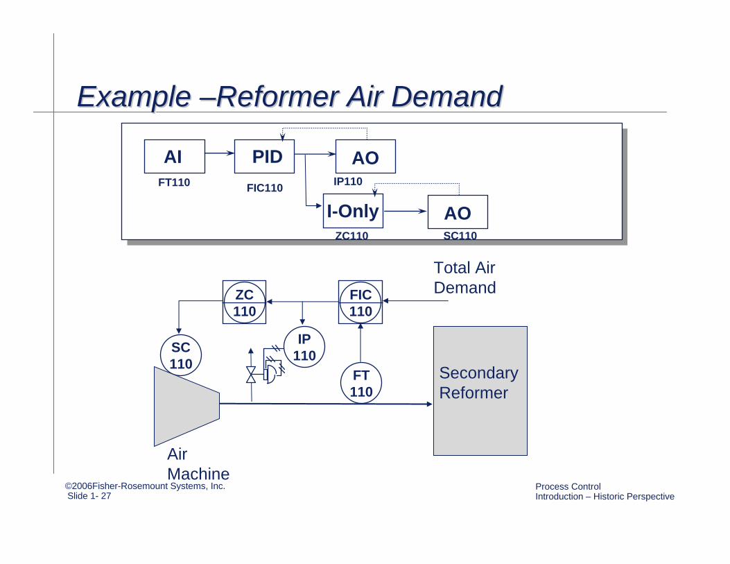
Example –Reformer Air DemandExample Example ––Reformer Air DemandReformer Air Demand
ZC110
AI PID AOFT110 FIC110 IP110
ZC110
I-Only AOSC110
FIC110
FT110
SC110
Air Machine
Secondary Reformer
Total Air Demand
IP110
©2006Fisher-Rosemount Systems, Inc.Slide 1- 28
Process Control Introduction – Historic Perspective
Example – Valve Position ControlExample Example –– Valve Position ControlValve Position Control
©2006Fisher-Rosemount Systems, Inc.Slide 1- 29
Process Control Introduction – Historic Perspective
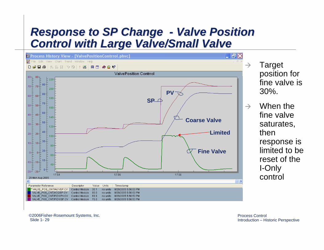
Response to SP Change - Valve Position Control with Large Valve/Small Valve Response to SP Change Response to SP Change -- Valve Position Valve Position Control with Large Valve/Small Valve Control with Large Valve/Small Valve
Target position for fine valve is 30%.
When the fine valve saturates, then response is limited to be reset of the I-Only control
Fine Valve
Coarse Valve
SPPV
Limited
©2006Fisher-Rosemount Systems, Inc.Slide 1- 30
Process Control Introduction – Historic Perspective
Valve Position Control – Strengths and WeaknessesValve Position Control Valve Position Control –– Strengths and Strengths and WeaknessesWeaknesses
Pro – Immediate control response is based on actuator with finest resolution and/or faster impact on controlled parameter.
Pro – Actuator with coarse resolution or slower impact on controlled parameter is automatically adjusted to maintain the output of the controller output long term at a specified operating point.
Con – The controller output may become limited in response to a large disturbance or setpoint change. For this case, the dynamic response becomes limited by the slower tuning of the I-only controller.
The features of split range control and valve position control may be combined to provide immediate response to large changes in demand while retaining the features of valve position control for normal changes.
©2006Fisher-Rosemount Systems, Inc.Slide 1- 31
Process Control Introduction – Historic Perspective
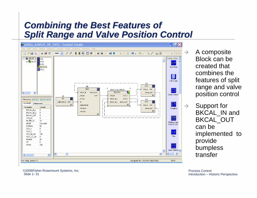
Combining the Best Features of Split Range and Valve Position ControlCombining the Best Features of Combining the Best Features of Split Range and Valve Position ControlSplit Range and Valve Position Control
A composite Block can be created that combines the features of split range and valve position control
Support for BKCAL_IN and BKCAL_OUT can be implemented to provide bumpless transfer
©2006Fisher-Rosemount Systems, Inc.Slide 1- 32
Process Control Introduction – Historic Perspective
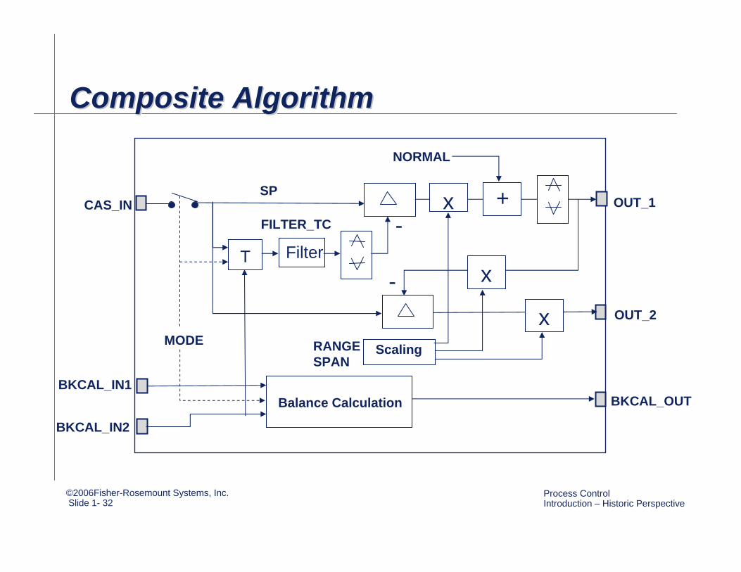
Composite AlgorithmComposite AlgorithmComposite Algorithm
Filter
CAS_IN
MODE
SP x +
x
x
T
ScalingRANGE SPAN
NORMAL
OUT_1
OUT_2
BKCAL_OUTBKCAL_IN1
BKCAL_IN2
Balance Calculation
-
-FILTER_TC

©2006Fisher-Rosemount Systems, Inc.Slide 1- 33
Process Control Introduction – Historic Perspective
Composite ImplementationComposite ImplementationComposite ImplementationParameters that must be configure are: FILTER_TC, SPAN (of SP), RANGE (of OUT1), and NORMAL (desired position )
The FILTER_TC should be configured similar to the reset time of the I-Only Controller that would be used for valve position control.
©2006Fisher-Rosemount Systems, Inc.Slide 1- 34
Process Control Introduction – Historic Perspective
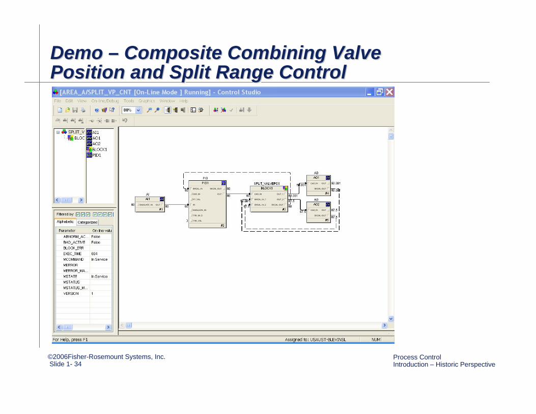
Demo – Composite Combining Valve Position and Split Range ControlDemo Demo –– Composite Combining Valve Composite Combining Valve Position and Split Range ControlPosition and Split Range Control

©2006Fisher-Rosemount Systems, Inc.Slide 1- 35
Process Control Introduction – Historic Perspective
Example: Response to SP Change Example: Response to SP Change Example: Response to SP Change For small changes in SP or load disturbance, the response is similar to that provided by valve position control
For large changes in SP or load disturbance, the immediate response is similar to split range control
SP, PV
OUT of PID
Fine Valve
Coarse Valve
Small change Large change
©2006Fisher-Rosemount Systems, Inc.Slide 1- 36
Process Control Introduction – Historic Perspective
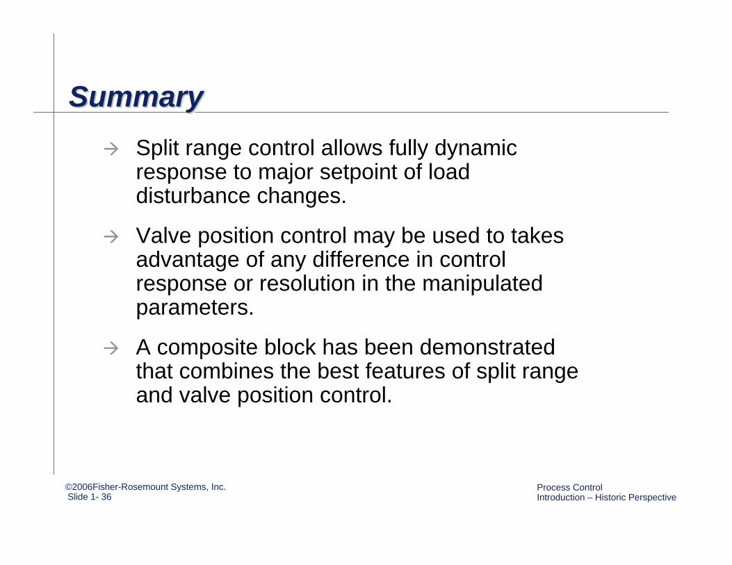
SummarySummarySummarySplit range control allows fully dynamic response to major setpoint of load disturbance changes.
Valve position control may be used to takes advantage of any difference in control response or resolution in the manipulated parameters.
A composite block has been demonstrated that combines the best features of split range and valve position control.