control volume analysis - memorial university of newfoundland · control volume analysis •...
TRANSCRIPT

Faculty of Engineering and Applied Science Memorial University of Newfoundland
St. John’s, Newfoundland, Canada
1
Control Volume Analysis
Faculty of Engineering and Applied Science Memorial University of Newfoundland
St. John’s, Newfoundland, Canada
2
Control Volume Analysis • Consider the control volume in more detail
for both mass and energy – open and closed systems – steady and transient analysis
• Control Volume – encloses the system or region of interest – can have multiple inlets/exits or none at all if it
is a closed system (as we have seen) – is important much like the free body diagram
Faculty of Engineering and Applied Science Memorial University of Newfoundland
St. John’s, Newfoundland, Canada
3
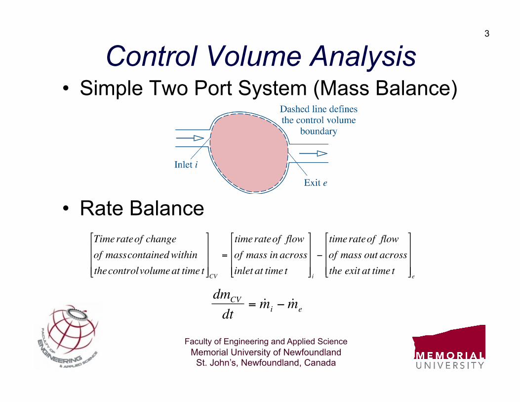
Control Volume Analysis • Simple Two Port System (Mass Balance)
• Rate Balance
€
Time rateof changeof masscontainedwithinthecontrolvolumeat time t
⎡
⎣
⎢ ⎢ ⎢
⎤
⎦
⎥ ⎥ ⎥ CV
=
time rateof flowof mass in acrossinlet at time t
⎡
⎣
⎢ ⎢ ⎢
⎤
⎦
⎥ ⎥ ⎥ i
−
time rateof flowof mass out acrossthe exit at time t
⎡
⎣
⎢ ⎢ ⎢
⎤
⎦
⎥ ⎥ ⎥ e
€
dmCV
dt= ˙ m i − ˙ m e

Faculty of Engineering and Applied Science Memorial University of Newfoundland
St. John’s, Newfoundland, Canada
4
Conservation of Mass • Extended to multiple inlet/exit control
volumes, we may write the balance as:
• If there are no inlets/exits, the the system is closed and we have:
€
dmCV
dt= ˙ m i
inlets∑ − ˙ m e
exits∑
€
dmCV
dt= 0 or mCV = Constant
Faculty of Engineering and Applied Science Memorial University of Newfoundland
St. John’s, Newfoundland, Canada
5
Conservation of Mass • If the system is under steady state then
the left hand side of the mass balance becomes:
or
• We will examine many problems involving steady and unsteady flow
€
dmCV
dt= 0
€
˙ m iinlets∑ = ˙ m e
exits∑
Faculty of Engineering and Applied Science Memorial University of Newfoundland
St. John’s, Newfoundland, Canada
6
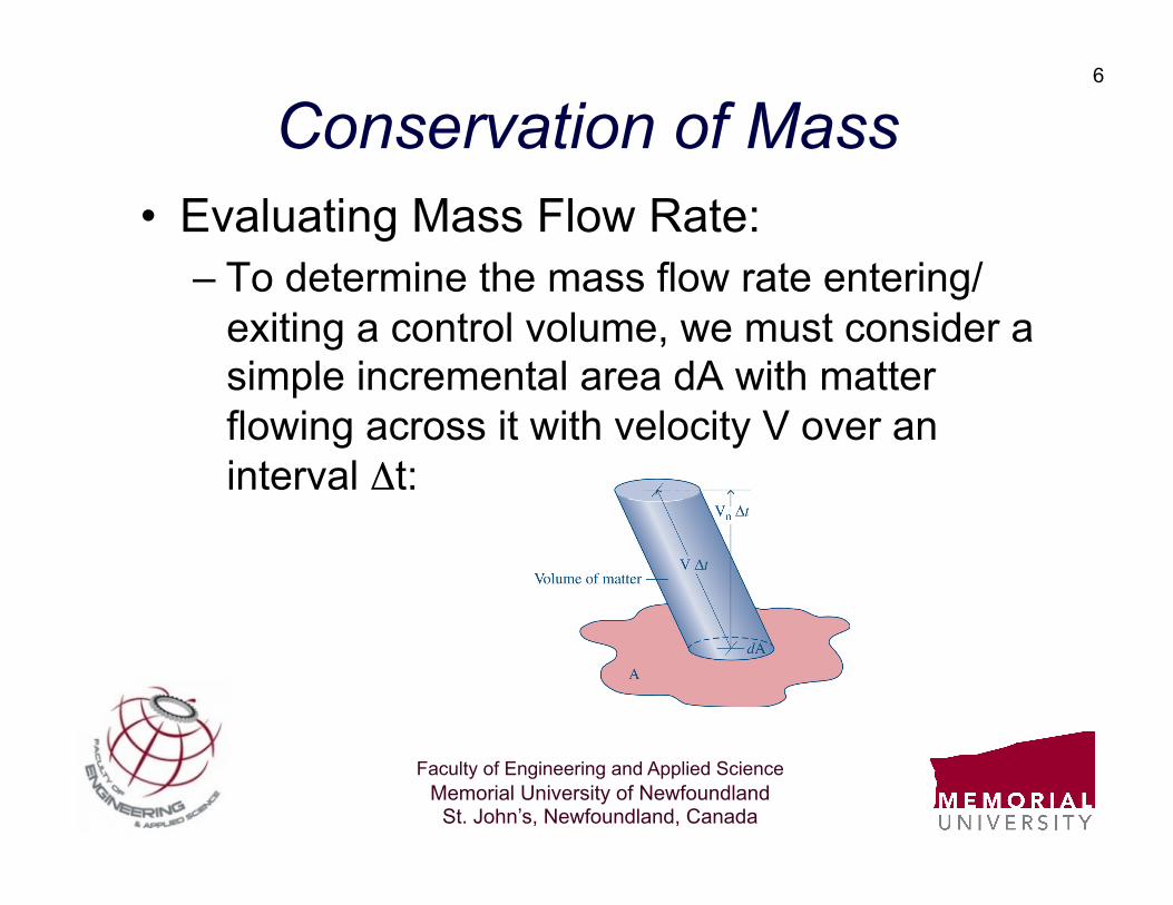
Conservation of Mass • Evaluating Mass Flow Rate:
– To determine the mass flow rate entering/exiting a control volume, we must consider a simple incremental area dA with matter flowing across it with velocity V over an interval Δt:
Faculty of Engineering and Applied Science Memorial University of Newfoundland
St. John’s, Newfoundland, Canada
7
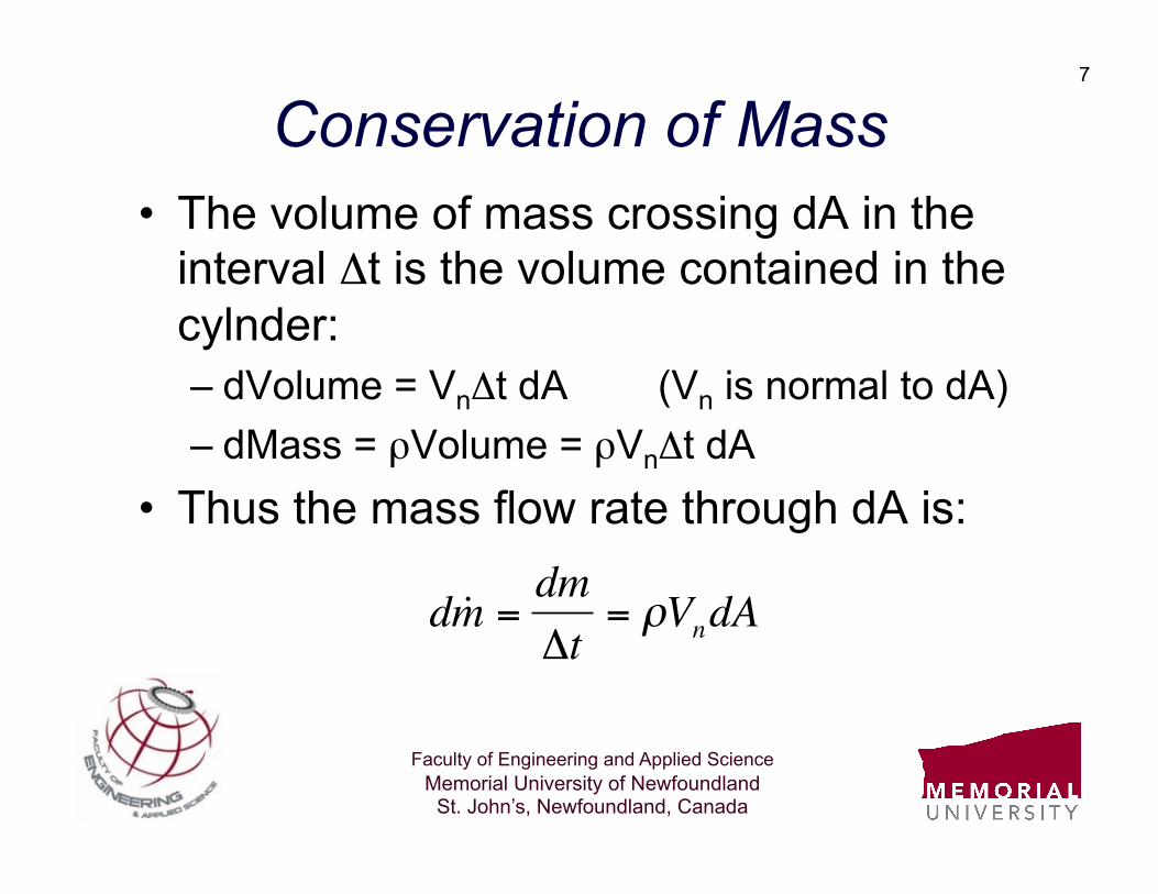
Conservation of Mass • The volume of mass crossing dA in the
interval Δt is the volume contained in the cylnder: – dVolume = VnΔt dA (Vn is normal to dA) – dMass = ρVolume = ρVnΔt dA
• Thus the mass flow rate through dA is:
€
d ˙ m = dmΔt
= ρVndA
Faculty of Engineering and Applied Science Memorial University of Newfoundland
St. John’s, Newfoundland, Canada
8
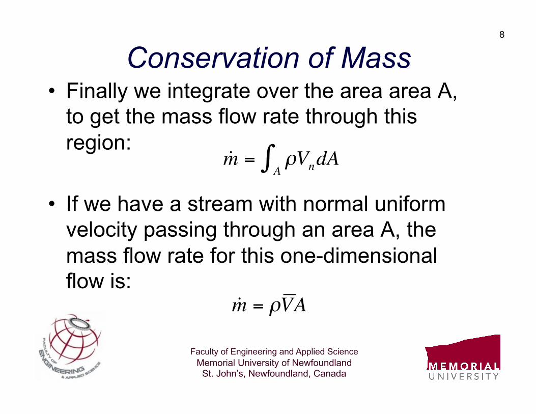
Conservation of Mass • Finally we integrate over the area area A,
to get the mass flow rate through this region:
• If we have a stream with normal uniform velocity passing through an area A, the mass flow rate for this one-dimensional flow is:
€
˙ m = ρVndAA∫
€
˙ m = ρV A

Faculty of Engineering and Applied Science Memorial University of Newfoundland
St. John’s, Newfoundland, Canada
9
Conservation of Mass • The Conservation of Mass equation for a
multiport control volume can then be taken as:
• This will be the starting point for all future analyses. We will then make assumptions as to steady/unsteady or open/closed. €
dmCV
dt= ρV A( )i
inlets∑ − ρV A( )e
exits∑
Faculty of Engineering and Applied Science Memorial University of Newfoundland
St. John’s, Newfoundland, Canada
10
Example - 1 • Steam enters a turbine through a pipe with
a 15 cm diameter. The inlet steam velocity is 90 m/s, and it has a pressure of 20 MPa and temperature of 600 C. The exit pipe has a diameter of 60 cm, and the exit pressure is 300 kPa and temperature of 150 C. Assuming steady state flow, calculate the mass flow rate through the turbine and the exit velocity.
Faculty of Engineering and Applied Science Memorial University of Newfoundland
St. John’s, Newfoundland, Canada
11
Example - 2 • An air compressor supplies air to a rigid tank that
has a volume of 4 m3. Initially the pressure and temperature of the air in the tank are 101 kPa and 35 C. The supply pipe is 7 cm in diameter and the feed velocity is steady at 12 m/s. The pressure and temperature of the air in the inlet pipe are 600 kPa and 35 C. Find: – Time rate of change of mass inside the tank – Mass of air added to the tank if the compressor stops when
pressure and temperature are 400 kPa and 55 C – Time the compressor is running to fill tank

Faculty of Engineering and Applied Science Memorial University of Newfoundland
St. John’s, Newfoundland, Canada
12
Conservation of Energy: First Law of Thermodynamics
Faculty of Engineering and Applied Science Memorial University of Newfoundland
St. John’s, Newfoundland, Canada
13
Introduction • The First Law of Thermodynamics states
that energy must be conserved, i.e. it can not be created or destroyed.
• The energy balance for a control volume follows a similar approach to that for Conservation of Mass, but has additional considerations.
• As before we will consider open and closed systems and steady/transient flows
Faculty of Engineering and Applied Science Memorial University of Newfoundland
St. John’s, Newfoundland, Canada
14
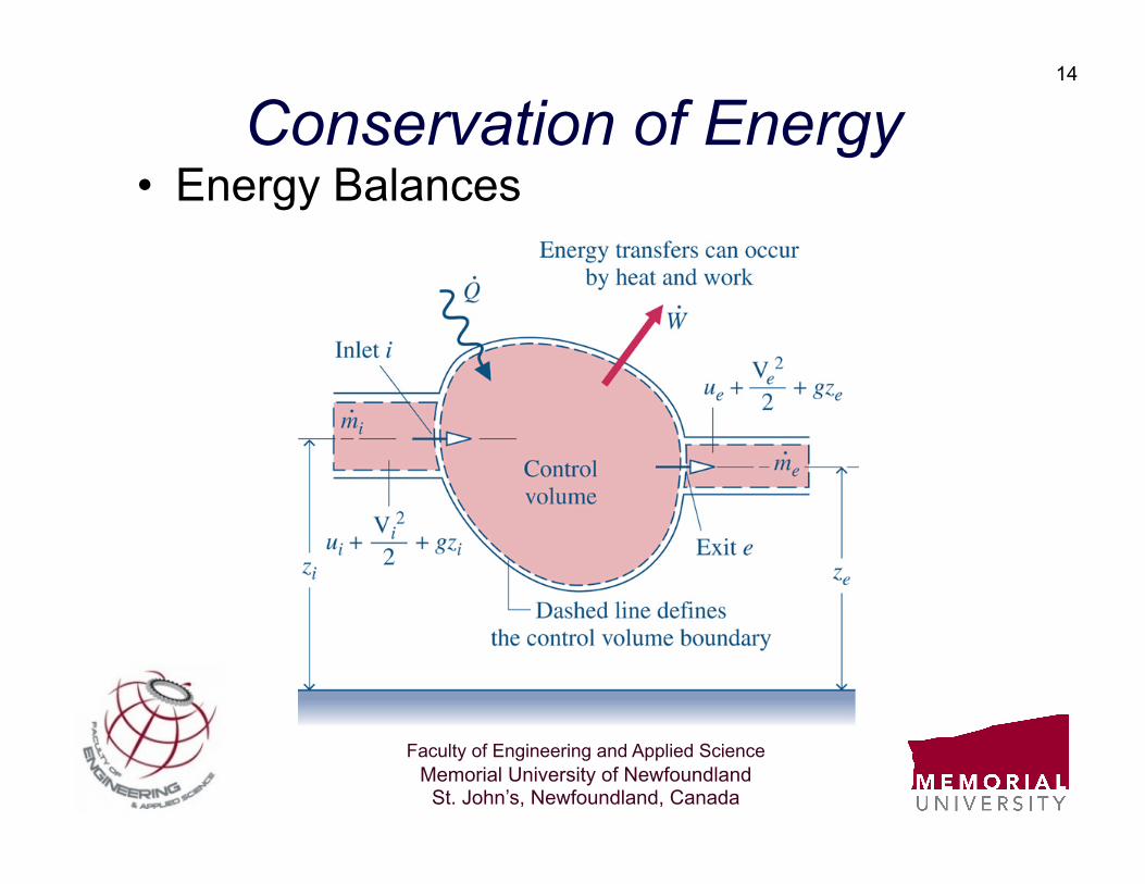
Conservation of Energy • Energy Balances

Faculty of Engineering and Applied Science Memorial University of Newfoundland
St. John’s, Newfoundland, Canada
15
Conservation of Energy • Rate Balance
• Referring to the figure we see that in equation form this becomes: €
time rateof changeof energy containedwithin thecontrolvolume at time t
⎡
⎣
⎢ ⎢ ⎢ ⎢
⎤
⎦
⎥ ⎥ ⎥ ⎥
CV
=
net rateof energytransferred inasheat transferat time t
⎡
⎣
⎢ ⎢ ⎢ ⎢
⎤
⎦
⎥ ⎥ ⎥ ⎥
˙ Q
−
net rateof energytransferredoutaswork at time t
⎡
⎣
⎢ ⎢ ⎢
⎤
⎦
⎥ ⎥ ⎥ ˙ W
+
net rateof energytransfer int o thecontrol volumeaccompanyingmassflow through ports
⎡
⎣
⎢ ⎢ ⎢ ⎢ ⎢ ⎢
⎤
⎦
⎥ ⎥ ⎥ ⎥ ⎥ ⎥
€
dECV
dt= ˙ Q − ˙ W + ˙ m i ui +
Vi2
2+ gzi
⎛
⎝ ⎜
⎞
⎠ ⎟ − ˙ m e ue +
Ve2
2+ gze
⎛
⎝ ⎜
⎞
⎠ ⎟

Faculty of Engineering and Applied Science Memorial University of Newfoundland
St. John’s, Newfoundland, Canada
16
Conservation of Energy • If the control volume contains multiple inlets/
exits then we may write:
• We must now consider what the work term really represents. At this point it is the net work transfer.
• It is more useful to account for this in more detail as there are different types of work.
€
dECV
dt= ˙ Q − ˙ W + ˙ m i
inlets∑ ui +
Vi2
2+ gzi
⎛
⎝ ⎜
⎞
⎠ ⎟ − ˙ m e
exits∑ ue +
Ve2
2+ gze
⎛
⎝ ⎜
⎞
⎠ ⎟
Faculty of Engineering and Applied Science Memorial University of Newfoundland
St. John’s, Newfoundland, Canada
17
Conservation of Energy • Since work is always done on or by a
control volume when matter flows across inlets/exits, it is convenient to separate work into two contributions: – work associated with fluid pressure – work associated with rotating shafts, boundary
displacement, etc • The former is referred to frequently as
“flow work”

Faculty of Engineering and Applied Science Memorial University of Newfoundland
St. John’s, Newfoundland, Canada
18
Conservation of Energy • Work due to fluid flow can be considered
if consider that pressure times area is a force, p*A, and force times velocity, F*V, is power (or work), thus:
• We will define the work term as:
€
˙ W = ˙ W CV + pe AeVeexits∑ − piAiVi
inlets∑
€
time rate of energytransfer by workdue to flow
⎡
⎣
⎢ ⎢ ⎢
⎤
⎦
⎥ ⎥ ⎥
= pAV
Faculty of Engineering and Applied Science Memorial University of Newfoundland
St. John’s, Newfoundland, Canada
19
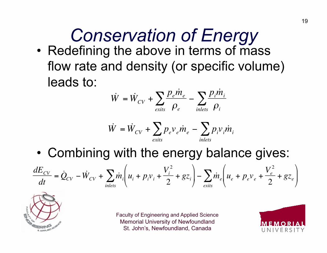
Conservation of Energy • Redefining the above in terms of mass
flow rate and density (or specific volume) leads to:
• Combining with the energy balance gives: €
˙ W = ˙ W CV +pe ˙ m eρeexits
∑ −pi ˙ m iρiinlets
∑
€
˙ W = ˙ W CV + peve ˙ m eexits∑ − pivi ˙ m i
inlets∑
€
dECV
dt= ˙ Q CV − ˙ W CV + ˙ m i
inlets∑ ui + pivi +
Vi2
2+ gzi
⎛
⎝ ⎜
⎞
⎠ ⎟ − ˙ m e
exits∑ ue + peve +
Ve2
2+ gze
⎛
⎝ ⎜
⎞
⎠ ⎟
Faculty of Engineering and Applied Science Memorial University of Newfoundland
St. John’s, Newfoundland, Canada
20
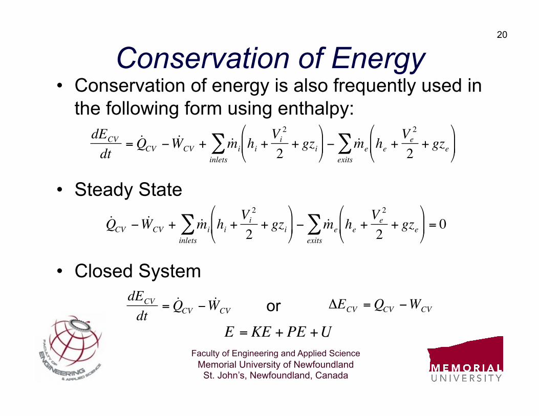
Conservation of Energy • Conservation of energy is also frequently used in
the following form using enthalpy:
• Steady State
• Closed System
€
dECV
dt= ˙ Q CV − ˙ W CV + ˙ m i
inlets∑ hi +
Vi2
2+ gzi
⎛
⎝ ⎜
⎞
⎠ ⎟ − ˙ m e
exits∑ he +
Ve2
2+ gze
⎛
⎝ ⎜
⎞
⎠ ⎟
€
˙ Q CV − ˙ W CV + ˙ m iinlets∑ hi +
Vi2
2+ gzi
⎛
⎝ ⎜
⎞
⎠ ⎟ − ˙ m e
exits∑ he +
Ve2
2+ gze
⎛
⎝ ⎜
⎞
⎠ ⎟ = 0
€
dECV
dt= ˙ Q CV − ˙ W CV
€
ΔECV =QCV −WCVor
€
E = KE + PE +U
Faculty of Engineering and Applied Science Memorial University of Newfoundland
St. John’s, Newfoundland, Canada
21
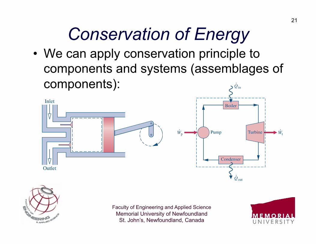
Conservation of Energy • We can apply conservation principle to
components and systems (assemblages of components):
Faculty of Engineering and Applied Science Memorial University of Newfoundland
St. John’s, Newfoundland, Canada
22
Example - 3 • Re-consider Example 1 earlier, but this
time determine the work done by the superheated steam passing through the turbine. Assume the turbine is insulated, such that there is no heat loss to the surroundings. Also, consider the effect of neglecting the kinetic energy.
Faculty of Engineering and Applied Science Memorial University of Newfoundland
St. John’s, Newfoundland, Canada
23
Example - 4 • A stream of liquid water at 300 kPa and
20 C is mixed with steam at 300 kPa and 250 C in an adiabatic mixing chamber. The steam has a flow rate of 90 kg/s and the mixture leaves at a pressure of 300 kPa. Determine the mass flow rate of the liquid entering the chamber and the mass flow rate of the mixture leaving the chamber.
Faculty of Engineering and Applied Science Memorial University of Newfoundland
St. John’s, Newfoundland, Canada
24
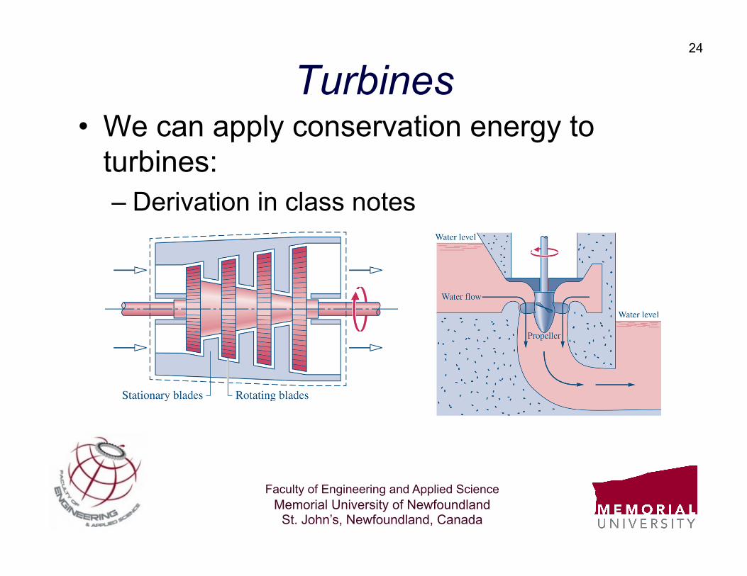
Turbines • We can apply conservation energy to
turbines: – Derivation in class notes
Faculty of Engineering and Applied Science Memorial University of Newfoundland
St. John’s, Newfoundland, Canada
25
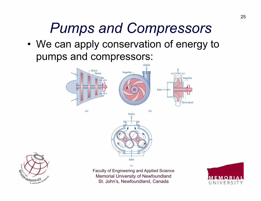
Pumps and Compressors • We can apply conservation of energy to
pumps and compressors:
Faculty of Engineering and Applied Science Memorial University of Newfoundland
St. John’s, Newfoundland, Canada
26
Example - 5 • A pump is used to raise water steadily at a
volume flow rate of 50 L/s through an elevation change of change of 100 m. The pump inlet has a diameter of 15 cm and the exit a diameter of 18 cm. The water is drawn from a supply at 20 C and is discharge to atmospheric pressure of 100 kPa. Assuming that the pump is well insulated and that frictional heating effects are small, and assuming that the exit temperature is approximately the same as the inlet, what is the power (work) required for this pump?
Faculty of Engineering and Applied Science Memorial University of Newfoundland
St. John’s, Newfoundland, Canada
27
Example - 6 • A compressor is used to compress
atmospheric air at 100 kPa and 20 C to a pressure of 1 MPa. The compressor loses approximately 10% of the energy input as work through heat loss to the surroundings. Air enters the compressor at 50 m/s though an inlet having a diameter of 10 cm and leaves at 120 m/s through an exit having a diameter of 2.5 cm. Determine the exit air temperature and the input power required to the compressor.

Faculty of Engineering and Applied Science Memorial University of Newfoundland
St. John’s, Newfoundland, Canada
28
Heat Exchangers • We can apply conservation of energy to
heat exchangers:
Faculty of Engineering and Applied Science Memorial University of Newfoundland
St. John’s, Newfoundland, Canada
29
Example - 7 • A heat exchanger is designed to use exhaust
steam from a turbine to heat air for space heating. Steam enters the heat exchanger with a flow rate of 1.2 kg/s a pressure of 200 kPa and a temperature of 200 C. The steam leaves the heat exchanger as a saturated vapor at 200 kPa. The air enters the heat exchanger at 20 C and 101 kPa with a flow rate of 3 kg/s, and leaves at a pressure of 101 kPa. Assuming that losses to the surroundings are negligible, calculate the exit air temperature.
Faculty of Engineering and Applied Science Memorial University of Newfoundland
St. John’s, Newfoundland, Canada
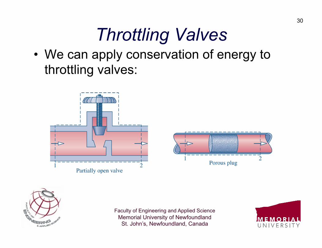
30
Throttling Valves • We can apply conservation of energy to
throttling valves:
Faculty of Engineering and Applied Science Memorial University of Newfoundland
St. John’s, Newfoundland, Canada
31
Example - 8 • A throttling valve is used in a refrigeration
system. Saturated liquid Refrigerant 22 at 10 bar is passed through a throttling valve and discharged at 1 bar. Determine the inlet and exit temperatures and the exit quality assuming that heat transfer and kinetic energy effects are negligible.

Faculty of Engineering and Applied Science Memorial University of Newfoundland
St. John’s, Newfoundland, Canada
32
Unsteady Processes • We will now consider two unsteady
thermodynamic processes: – Charging (filling) of a rigid vessel – Discharging (emptying) of a rigid vessel
• Apply conservation of mass and energy to each case develop expressions for each process: – Derivation in class notes
Faculty of Engineering and Applied Science Memorial University of Newfoundland
St. John’s, Newfoundland, Canada
33
Example - 9 • High pressure CO2 at 1.0 MPa and 57 C
enters an initially evacuated rigid tank. The gas stops flowing when the pressure in the tank reaches that of the supply line. Assuming that the process occurs quick enough so that heat transfer with the surroundings is negligible, determine the final temperature of the gas inside the vessel if the volume of the tank is 0.5 m3. How much mass entered the vessel?
Faculty of Engineering and Applied Science Memorial University of Newfoundland
St. John’s, Newfoundland, Canada
34
Example - 10 • Air at 5 bar and 25 C is discharged from a
vessel with a volume of 0.5 L. The gas stops flowing when the pressure in the vessel is reduced to 4.0 bar. Assuming that the process occurs quick enough so that heat transfer with the surroundings is negligible, determine the final temperature of the gas remaining inside the vessel. How much mass exited the vessel?
Faculty of Engineering and Applied Science Memorial University of Newfoundland
St. John’s, Newfoundland, Canada
35
Thermodynamic Cycles • We will now consider two fundamental
thermodynamic cycles – Simple steam (vapor) power cycle – Simple gas power cycle – Simple vapor refrigeration cycle
• Basic steps in a cycle analysis: – Establish the thermodynamic states at inlet/exit of
major components – Use energy/mass balances to close out the
analysis as required
Faculty of Engineering and Applied Science Memorial University of Newfoundland
St. John’s, Newfoundland, Canada
36
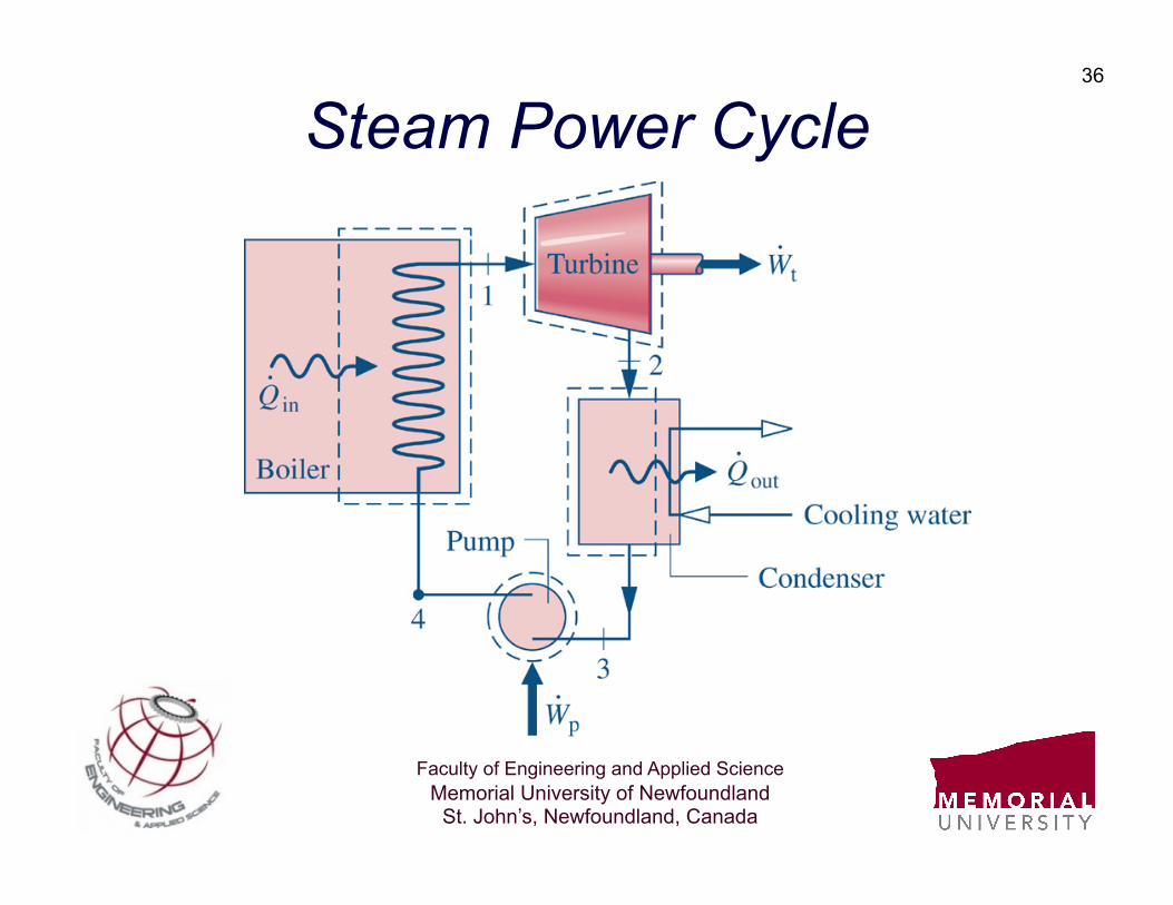
Steam Power Cycle
Faculty of Engineering and Applied Science Memorial University of Newfoundland
St. John’s, Newfoundland, Canada
37
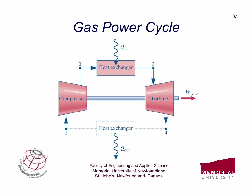
Gas Power Cycle
Faculty of Engineering and Applied Science Memorial University of Newfoundland
St. John’s, Newfoundland, Canada
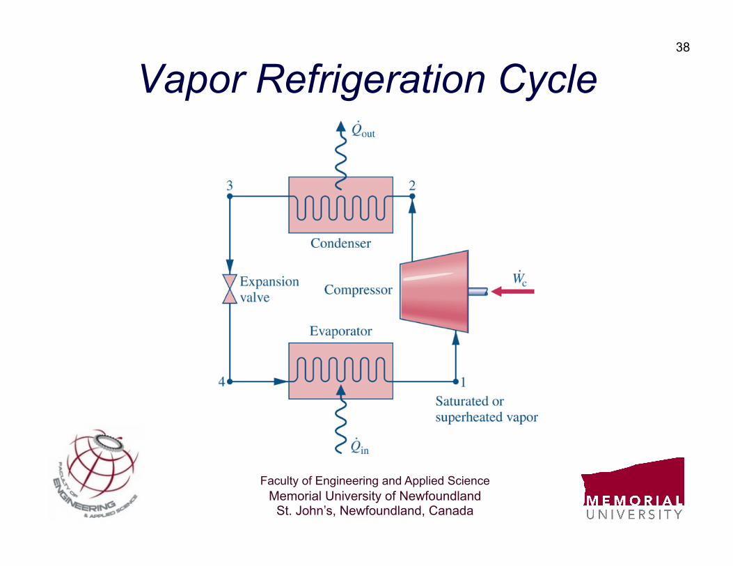
38
Vapor Refrigeration Cycle
Faculty of Engineering and Applied Science Memorial University of Newfoundland
St. John’s, Newfoundland, Canada
39
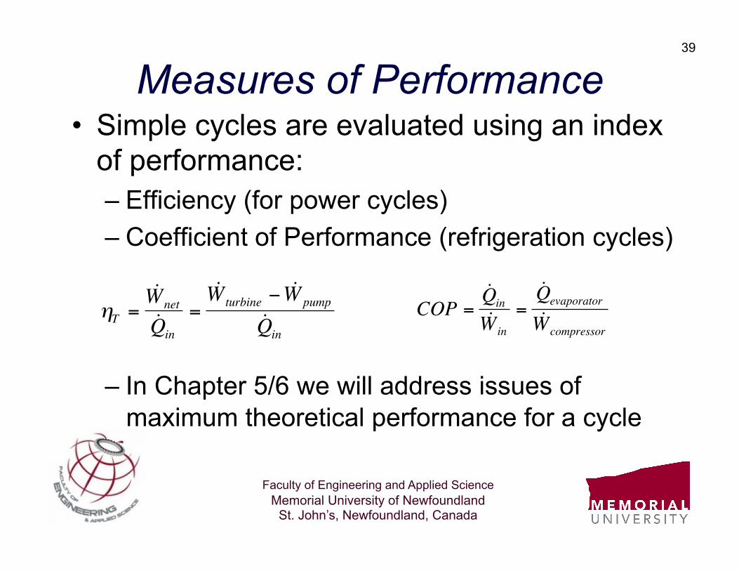
Measures of Performance • Simple cycles are evaluated using an index
of performance: – Efficiency (for power cycles) – Coefficient of Performance (refrigeration cycles)
– In Chapter 5/6 we will address issues of maximum theoretical performance for a cycle €
ηT =˙ W net˙ Q in
=˙ W turbine − ˙ W pump
˙ Q in
€
COP =˙ Q in˙ W in
=˙ Q evaporator
˙ W compressor
Faculty of Engineering and Applied Science Memorial University of Newfoundland
St. John’s, Newfoundland, Canada
40
Example - 11 • A simple steam cycle uses water as a working
fluid which circulates at 80 kg/s. The boiler pressure pressure is 6 MPa and the condenser pressure is 10 kPa. Steam enters the turbine at 600 C and is discharged with a quality of 0.85 at 10 kPa. Saturated liquid at 10 kPa, is discharged from the condenser. Determine the power developed by the cycle and the thermal efficiency.
Faculty of Engineering and Applied Science Memorial University of Newfoundland
St. John’s, Newfoundland, Canada
41
Example - 12 • Air at 100 kPa and 37 C enters an ideal
adiabatic compressor with a compression ratio of 10:1 and a mass flow rate of 10 kg/s. The high pressure air is then heated in a combustion process at constant pressure which raises its temperature to 1227 C. The hot gas is then expanded through a turbine to 100 kPa and leaves at 497 C. Determine the net power generated and the thermal efficiency for this cycle.
Faculty of Engineering and Applied Science Memorial University of Newfoundland
St. John’s, Newfoundland, Canada
42
Example - 13 • Refrigerant 22 enters the compressor of an
ideal refrigeration cycle with a flow rate of 15 m3/min, and is compressed from a saturated vapor at 1 bar to a pressure of 9 bar and temperature of 60 C. The refrigerant leaves the condenser as a saturated liquid and is expanded through a throttling valve to a pressure of 1.0 bar. Determine the compressor power, refrigeration capacity and coefficient of performance for the cycle.