controlador foxboro 762cna
TRANSCRIPT

762CNASINGLE STATION MICRO
®
Controller
Instruction MI 018-885February 1998

Foxboro, EXACT, I/A Series, and SINGLE STATION MICRO are registered trademarks of The Foxboro Company.
The Intelligent Automation People is a registered service mark of The Foxboro Company.
Copyright 1996-1998 by The Foxboro Company
All rights reserved
ii 762CNA Controller MI 018-885 February 1998
Contents
Figures vii
Tables ix
Preface xiiiSafety Considerations · xiiiOrganization · xiiiIntended Audience · xiiiHow to Use This Manual · xivUser Feedback · xv
1 Quick Check 1Seating the NOVRAM · 2Connecting to Power Source · 3Controller Display · 4Changing the Display · 6Reading Additional Information · 7Reading Additional Information (cont.) · 8Looking for More Information? · 8
2 Product Overview 11Description · 12Functional Block Diagram · 13Front Panel · 18
Display Functions · 18Display Functions (cont.) · 19Keypad Functions · 19
3 Installation 23Important Safety Precautions · 24
Shock Hazards · 24Explosion Hazards · 24
Unpacking · 24Controller Identification · 25Positioning Links · 26Installation Procedure · 27
Removing Input Range Resistors · 29Removing Input Range Resistors (cont.) · 30
Signal Wiring Guidelines · 30Connecting Wires to Terminals · 30Connecting Wires to Terminals (cont.) · 31Wiring to Controller · 31
Input Signal Wiring · 32Input Signal Terminal/Wire Designations · 32Analog Input Signal Wiring · 33Frequency Input Signal Wiring · 34Pulse Input Wiring · 36RTD and Contact Input Wiring · 37
Output Signal Wiring · 38Output Signal Terminal/Wire Designations · 38Output Signal Wiring Examples · 38
Serial Communication Wiring · 39Terminal/Wire Designations · 39Wiring to an RS-485 Interface · 39
Power Wiring · 40Accessory Equipment · 41
Optional Surge Suppressor · 41Optional Surge Suppressor (cont.) · 42RS-232/RS-485 Converter · 42Wiring · 43OPTO-22 Board Model AC24 Converter Card
· 45
4 Configuration 49Introduction · 50
Planning Your Configuration · 50Planning Your Configuration (cont.) · 51Implementing Your Configuration · 54Implementing Your Configuration (cont.) · 55Implementing Your Configuration (cont.) · 56
Common Configuration Functions · 58Security · 58Control Type and Tuning · 58Control Type and Tuning (cont.) · 59
MI 018-885 February 1998 762CSA Controller - Contents iii
Input Signals · 59Input Signals (cont.) · 60Input Signal Conditioning and Scaling · 60Output Signals · 62Display Features · 62Auto/Manual Control (A/M) · 63
Alarms · 64General Information · 64Forms of Alarms · 65Types of Alarms · 66Alarm Action · 70Configuring, Tuning, and Displaying Alarms
· 70Configuring, Tuning, and Displaying Alarms
(cont.) · 71Alarm Configuration Examples · 71
Alternate Station Configurations · 76Dual Controller · 76Cascade Controller · 76Auto Selector Controller · 78Auto/Manual Station · 79Indicator Station · 79
Additional Configuration Functions · 80Logic Gates · 81Calculations · 82Calculations (cont.) · 83Dynamic Compensation · 86Dynamic Compensation (cont.) · 87Totalizers · 89Totalizers (cont.) · 90Set Point · 91Set Point (cont.) · 92Set Point Limits · 93Ratio Control · 93Output Summing and Multiplying · 94Output Tracking · 94Split Range Output · 94Split Range Output (cont.) · 97Output Limits · 98Output Action · 99Output Upon Restart (STARTUP) · 99Output Reverse · 99Output Bargraph · 99Characterizers · 100Nonlinear Control · 100pH Display · 100Serial Communications · 101
Toggle · 102Batch Control · 103Integral Feedback · 103Rate of Change Alarms · 104
Configuration Copy Accessory · 105
5 Operation 109Functions · 110
Block Diagram · 110Controls and Indicators · 113
Keypad · 115Structure Diagrams · 115Modes of Operation · 116SET OPTUNE · 116NORMAL Mode Operation · 117
Entering a Passcode · 117Reading Values of Variables · 118Changing the Control Status · 121Changing Set Point, Output, and Variables · 121Changing Set Point, Output, and Variables
(cont.) · 122Changing Set Point, Output, and Variables
(cont.) · 123Displaying/Acknowledging Alarms · 123Changing Alarm Settings · 126Enabling/Disabling EXACT Tuning · 127Switching Faceplate Displays · 127Switching Modes · 127
Operation as an Auto/Manual Station · 128Operation as a 3-Variable Indicator Station · 129Operation as an Auto-Selector Station · 130Operation as a Cascade Control Station · 130Totalizer Operation · 131READ Mode Operation · 132
6 EXACT Tuning 135Technical Description · 136
Benefits of EXACT Tuning · 136EXACT Steps · 136EXACT Steps (cont.) · 137Determining Process Response (Pattern
Recognition) · 137Determining Process Response (cont.) · 138Calculating PID Values (STUN Algorithm)
· 138Calculating Initial Parameters (PTUN
Algorithm) · 140User-adjustable Parameters · 141
iv 762CNA Controller - Contents MI 018-885 February 1998
Using EXACT Tuning with 762C Controllers · 144Use of Structure Diagrams · 144Keys Used with EXACT · 145Responding to a ? Prompt · 145Configuring EXACT · 147Status Messages · 147Status Messages (cont.) · 148Messages — Read EXACT Pretune · 148Messages — Read EXACT Self-tune · 148Messages — Read EXACT Entries · 149
Tutorial Example · 150Tutorial Example (cont.) · 152Tutorial Example (cont.) · 153Tutorial Example (cont.) · 154EXACT Parameter Tables · 155
Parameter Limits and Values · 156
7 Calibration, Troubleshooting, Maintenance 159
Calibration · 160Frequency of Calibration · 160Calibration Equipment Accuracy · 160Calibration Connections · 160Calibration Procedures · 160Controller Range Conversion · 166Output 2 Selection · 172
Troubleshooting · 173Maintenance · 176
General Information · 176Removal and Replacement of Parts · 176
Appendix A - Specifications 183Functional Specifications · 183Physical Specifications · 186Operating and Storage Conditions · 187Electrical Safety Specifications · 187Performance Specifications · 188Optional Features and Accessories · 189
Appendix B - Configuration Worksheets 193Factory Preconfiguration Diagrams · 211
Appendix C - Structure Diagrams 237Structure Diagram 1 – READ · 239Structure Diagrams 2 and 3 · 240Structure Diagram 8 · 243
Appendix D - Parts List 247762CNA SINGLE STATION MICRO Controller
with Integral Power Supply Style AA*, DIN Panel Mounted · 247Model Code · 247
Dimensional Print 255
Appendix F - Functional Diagram 261
Glossary 267
Index 287
MI 018-885 February 1998 762CSA Controller - Contents v

vi 762CNA Controller - Contents MI 018-885 February 1998
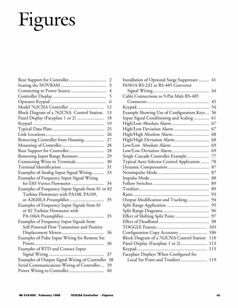
Figures
Rear Support for Controller................................ 2Seating the NOVRAM ....................................... 3Connecting to Power Source .............................. 4Controller Display .............................................. 5Operator Keypad ................................................ 6Model 762CNA Controller .............................. 12Block Diagram of a 762CNA Control Station. 13Panel Display (Faceplate 1 or 2) ....................... 18Keypad ............................................................. 19Typical Data Plate ............................................ 25Link Locations.................................................. 26Removing Controller from Housing................. 27Mounting of Controller.................................... 28Rear Support for Controller.............................. 28Removing Input Range Resistors ...................... 29Connecting Wires to Terminals........................ 30Terminal Identification..................................... 31Examples of Analog Input Signal Wiring .......... 33Examples of Frequency Input Signal Wiring
for E83 Vortex Flowmeter ............................ 34Examples of Frequency Input Signals from 81 or 82
Turbine Flowmeter with PA108, PA109, or A2020LA Preamplifier.............................. 35
Examples of Frequency Input Signals from 81 or 82 Turbine Flowmeter with PA-106A Preamplifier................................... 35
Examples of Frequency Input Signals from Self-Powered Flow Transmitter and Positive Displacement Meters .................................... 36
Examples of Pulse Input Wiring for Remote Set Points ........................................................... 36
Examples of RTD and Contact Input Signal Wiring ............................................... 37
Examples of Output Signal Wiring of Controller 38Serial Communications Wiring of Controller ... 39Power Wiring to Controller.............................. 40
Installation of Optional Surge Suppressor ......... 41F6501A RS-232 to RS-485 Converter
Signal Wiring................................................ 44Cable Connections to 9-Pin Male RS-485
Connector..................................................... 45Keypad.............................................................. 54Example Showing Use of Configuration Keys ... 56Input Signal Conditioning and Scaling ............. 61High/Low Absolute Alarm ................................ 67High/Low Deviation Alarm .............................. 67High/High Absolute Alarm............................... 68High/High Deviation Alarm ............................. 68Low/Low Absolute Alarm ................................ 69Low/Low Deviation Alarm................................ 69Single Cascade Controller Example................... 77Typical Auto Selector Control Application ....... 78Dynamic Compensation ................................... 87Nonimpulse Mode............................................ 87Impulse Mode................................................... 88Follow Switches ................................................ 89Totalizer............................................................ 89Ratio ................................................................. 93Output Modification and Tracking................... 94Split Range Application .................................... 95Split Range Diagrams........................................ 96Effect of Shifting Split Point ............................. 97Effect of Deadband ........................................... 98TOGGLE Feature........................................... 103Configuration Copy Accessory ........................ 106Block Diagram of a 762CNA Control Station 110Panel Display (Faceplate 1 or 2) ...................... 113Keypad............................................................ 115Faceplate Displays When Configured for
Local Set Point and Totalizer ...................... 119
MI 018-885 February 1998 762CSA Controller - Figures vii
Faceplate Displays When Configured for Workstation/Panel and Local/Remote Set Point and Totalizer............................... 120
Alarm Displays, High Alarm on Absolute Measurement (Level 1, Latched)................. 125
Flow Diagram for Enabling/Disabling EXACT Tuning ......................................... 127
3-Variable Indicator Station (Faceplate 1 or 2) 129Reading the Value of Totalizer Preset ............. 131Structure Diagram for READ
Mode Functions ......................................... 132Pattern Recognition Characteristics ................ 137STUN Algorithm State Diagram.................... 138Typical Process Response to Step Change in
Controller Output...................................... 140 Pretune States................................................ 141Maximum Wait Time (WMAX) .................... 142Period of Oscillation (T) ................................ 143Damping and Overshoot................................ 143Structure Diagram for EXACT ...................... 146General Flow Diagram for
Configuring EXACT.................................. 151
Structure Diagram 1 ....................................... 161Structure Diagram 2 ....................................... 162Terminal Connections for External Current
or Voltage Inputs ........................................ 163Terminal Connections for RTD Input
Calibration.................................................. 164Terminal Connections for Output Calibration 165Location of Input Range Resistors................... 166Addition of Input Range Resistors .................. 167RTD Printed Wiring Assembly ....................... 168Output 2 Jumper Location ............................. 172Location of Diagnostic Jumper........................ 174Controller Assembly Diagram ......................... 177Definition of Worksheet Contents ................. 194DIN Panel-Mounted Controller Assembly ..... 248Base Assembly ................................................ 250Electronics Module Assembly - Digital PWA . 251762CNA SINGLE STATION MICRO Controller ...................................................... 256Panel Cutout Dimensions .............................. 257
viii 762CNA Controller - Figures MI 018-885 February 1998
Tables
Keypad Functions.............................................. 7Link Locations................................................. 26Terminal and Wire designations for Input signal
Wiring......................................................... 32Output Signal Terminal and Wire Designations 38Serial Communications Terminal/Wire
Designations................................................ 39RS-232/RS-485 Converter Specifications ........ 42RS-485 Terminal Connections on
RS-232/485 Converter ................................ 43Content of Configuration Worksheet .............. 50Signal Distribution List ................................... 52Gate Input List ................................................ 53Keypad ............................................................ 54List of Characters............................................. 57Control Parameter Limits ................................ 58Alarm Configurations ...................................... 64High/Low alarms............................................. 67High/High Alarms........................................... 68Low/Low Alarms ............................................. 69Alarm Actions.................................................. 70Configuring Logic Gates.................................. 81Characters for Use in Calculations ................... 82Configuration of Serial Communication
Parameters ................................................. 101Effect of ∆/∇ Keys with R/L Not Configured. 121Operation of Remote/Local Controller
with Totalizer ............................................ 122Operation of Ratio Controller with Totalizer 123Keys Used with EXACT................................ 145
RD EXACT PTUNE..................................... 148RD EXACT STUN ....................................... 148Messages – RD EXACT ENT........................ 149EXACT Parameters........................................ 155EXACT Parameter Limits and Values ............ 156RTD Span Jumper Positions .......................... 168RTD Zero Elevation Jumper Positions........... 168RTD Temperature Difference Jumper
Positions .................................................... 169Output 2 Jumper Positions ............................ 172Diagnostics .................................................... 175Contact Input and Output Terminals ............ 175Fuses .............................................................. 178Functional Specifications — Standard Product 183Physical Specifications – Standard Product .... 186Operating and Storage Conditions ................. 187Electrical Classification .................................. 187Optional Features and Accessories.................. 189Signal Distribution List .................................. 195Gate Input List............................................... 195List of Characters ........................................... 196Characterization Curve Planning Table.......... 196Configuration Worksheets ............................. 197DIN Panel Mounted Controller
Assembly (Figure D-1) ............................... 249Base Assembly (Figure D-1) ........................... 250Digital PWA Portion of Electronics Module
Assembly (Figure D-3) ............................... 251Recommended Spare Parts Summary............. 251
MI 018-885 February 1998 762CSA Controller - Tables ix

x 762CNA Controller - Tables MI 018-885 February 1998

762C SINGLESTATION
MICROController
February 1998
Ð Preface • xiii Chapter 1 Quick Check • 1 Chapter 2 Product Overview • 11 Chapter 3 Installation • 23 Chapter 4 Configuration • 49 Chapter 5 Operation • 109 Chapter 6 EXACT Tuning • 135 Chapter 7 Calibration, Troubleshooting,
Maintenance • 159 Appendix A Specifications • 183 Appendix B Configuration Worksheets • 193 Appendix C Structure Diagrams • 237 Appendix D Parts List • 247 Appendix E Dimensional Print • 255 Appendix F Functional Diagram • 261 Glossary • 267 Index • 287
The Intelligent Automation People

xii 762CNA Controller MI 018-885 February 1998

MI 018-885 Februar
Preface
Safety ConsiderationsFoxboro products are designed and manufactured to minimize the risk of damage and injury to property and personnel. They meet or exceed applica-ble governmental and industry safety design standards. However, their safe use depends on proper installation, operation, and maintenance by you, the user. This manual provides you with the information needed for this. Please pay close attention to the portions of this manual that relate to safety.
OrganizationThis manual is designed to present in a single document all information about the 762C Controller needed by installers, process engineers, opera-tors, and maintenance personnel. A parts list is included in Appendix D and a dimensional print is included in Appendix E. The only additional docu-ment that may be needed for some installations is MI 018-888, Serial Com-munications Guide for 762C and 743CB Controllers, a reference intended primarily for programmers and software engineers.
Intended AudienceThis manual is intended for the following types of readers:• Process Operators• Process Engineers• Process Supervisors• Maintenance Personnel• Equipment Installers• Programmers/Software Engineers
y 1998 762CNA Controller - Preface xiii
How to Use This Manual
Process Operators
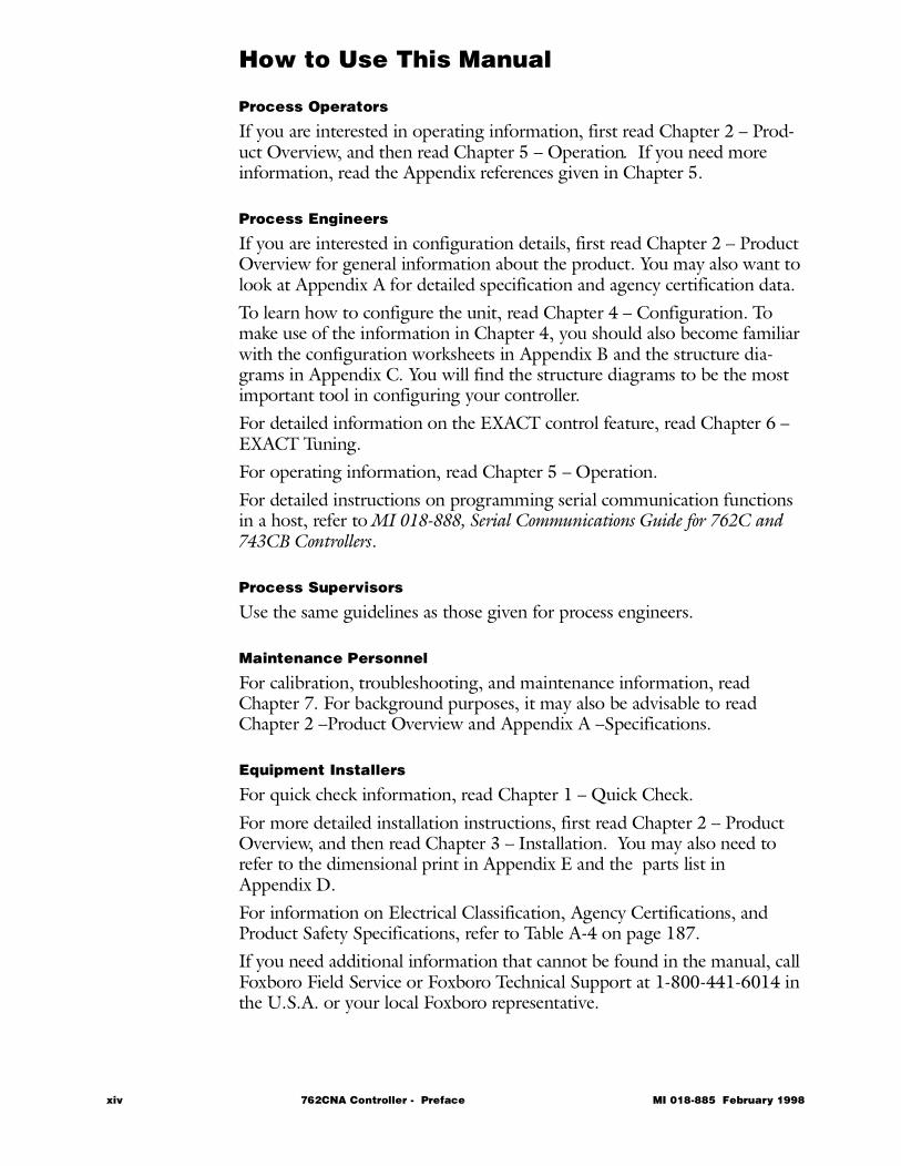
If you are interested in operating information, first read Chapter 2 – Prod-uct Overview, and then read Chapter 5 – Operation. If you need more information, read the Appendix references given in Chapter 5.
Process Engineers
If you are interested in configuration details, first read Chapter 2 – Product Overview for general information about the product. You may also want to look at Appendix A for detailed specification and agency certification data.To learn how to configure the unit, read Chapter 4 – Configuration. To make use of the information in Chapter 4, you should also become familiar with the configuration worksheets in Appendix B and the structure dia-grams in Appendix C. You will find the structure diagrams to be the most important tool in configuring your controller.For detailed information on the EXACT control feature, read Chapter 6 –EXACT Tuning.For operating information, read Chapter 5 – Operation.For detailed instructions on programming serial communication functions in a host, refer to MI 018-888, Serial Communications Guide for 762C and 743CB Controllers.
Process Supervisors
Use the same guidelines as those given for process engineers.
Maintenance Personnel
For calibration, troubleshooting, and maintenance information, read Chapter 7. For background purposes, it may also be advisable to read Chapter 2 –Product Overview and Appendix A –Specifications.
Equipment Installers
For quick check information, read Chapter 1 – Quick Check.For more detailed installation instructions, first read Chapter 2 – Product Overview, and then read Chapter 3 – Installation. You may also need to refer to the dimensional print in Appendix E and the parts list in Appendix D. For information on Electrical Classification, Agency Certifications, and Product Safety Specifications, refer to Table A-4 on page 187.If you need additional information that cannot be found in the manual, call Foxboro Field Service or Foxboro Technical Support at 1-800-441-6014 in the U.S.A. or your local Foxboro representative.
xiv 762CNA Controller - Preface MI 018-885 February 1998

Programmers/Software Engineers
Review Chapter 2 – Product Overview and the sections of Chapter 3 – Installation and Chapter 4 – Configuration that pertain to wiring and com-munications functions. Refer to MI 018-888, Serial Communications Guide for 762C and 743CB Controllers, for detailed descriptions of the controller protocol and communications functionality.
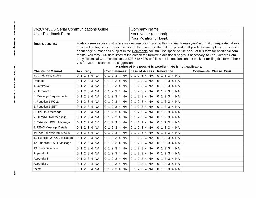
User FeedbackAfter you have had an opportunity to use this manual to install, configure, and operate the equipment, please fill out the user feedback form on the following page and return it to us.
MI 018-885 February 1998 762CNA Controller - Preface xv

xvi 762CNA Controller - Preface MI 018-885 February 1998
MI 0
18-8
85 F
ebru
ary 1
99
8 7
62
CN
A C
on
trolle
r - Pre
fac
e
xvii
________________________________________________________________________l. Please print information requested above, vided. If you find errors, please be specific n the back of this form for additional com-ages, if necessary, to The Foxboro Com-ons on the back for mailing this form. Thank
not applicable.Comments Please Print
‘
762C/743CB Serial Communications GuideUser Feedback Form
Company Name _________Your Name (optional) _____Your Position or Dept. ____
Instructions: Foxboro seeks your constructive suggestions for improving this manuathen circle rating scale for each section of the manual in the column proabout page number and subject in the Comments column. Use space oments. You may FAX both sides of the completed form with additional ppany, Technical Communications at 508-549-4380 or follow the instructiyou for your assistance and suggestions.
A rating of 0 is poor; 4 is excellent; NA isChapter of Manual Accuracy Completeness Ease of Access RelevanceTOC, Figures, Tables 0 1 2 3 4 NA 0 1 2 3 4 NA 0 1 2 3 4 NA 0 1 2 3 4 NA
Preface 0 1 2 3 4 NA 0 1 2 3 4 NA 0 1 2 3 4 NA 0 1 2 3 4 NA
1. Overview 0 1 2 3 4 NA 0 1 2 3 4 NA 0 1 2 3 4 NA 0 1 2 3 4 NA
2. Hardware 0 1 2 3 4 NA 0 1 2 3 4 NA 0 1 2 3 4 NA 0 1 2 3 4 NA
3. Message Requirements 0 1 2 3 4 NA 0 1 2 3 4 NA 0 1 2 3 4 NA 0 1 2 3 4 NA
4. Function 1 POLL 0 1 2 3 4 NA 0 1 2 3 4 NA 0 1 2 3 4 NA 0 1 2 3 4 NA
5. Function 1 SET 0 1 2 3 4 NA 0 1 2 3 4 NA 0 1 2 3 4 NA 0 1 2 3 4 NA
6. UPLOAD Message 0 1 2 3 4 NA 0 1 2 3 4 NA 0 1 2 3 4 NA 0 1 2 3 4 NA
7. DOWNLOAD Message 0 1 2 3 4 NA 0 1 2 3 4 NA 0 1 2 3 4 NA 0 1 2 3 4 NA
8. Extended POLL Message 0 1 2 3 4 NA 0 1 2 3 4 NA 0 1 2 3 4 NA 0 1 2 3 4 NA
9. READ Message Details 0 1 2 3 4 NA 0 1 2 3 4 NA 0 1 2 3 4 NA 0 1 2 3 4 NA
10. WRITE Message Details 0 1 2 3 4 NA 0 1 2 3 4 NA 0 1 2 3 4 NA 0 1 2 3 4 NA
11. Function 2 POLL Message 0 1 2 3 4 NA 0 1 2 3 4 NA 0 1 2 3 4 NA 0 1 2 3 4 NA
12. Function 2 SET Message 0 1 2 3 4 NA 0 1 2 3 4 NA 0 1 2 3 4 NA 0 1 2 3 4 NA
13. Error Detection 0 1 2 3 4 NA 0 1 2 3 4 NA 0 1 2 3 4 NA 0 1 2 3 4 NA
Appendix A 0 1 2 3 4 NA 0 1 2 3 4 NA 0 1 2 3 4 NA 0 1 2 3 4 NA
Appendix B 0 1 2 3 4 NA 0 1 2 3 4 NA 0 1 2 3 4 NA 0 1 2 3 4 NA
Appendix C 0 1 2 3 4 NA 0 1 2 3 4 NA 0 1 2 3 4 NA 0 1 2 3 4 NA
Index 0 1 2 3 4 NA 0 1 2 3 4 NA 0 1 2 3 4 NA 0 1 2 3 4 NA
xviii 762CNA Controller - Preface MI 018-885 February 1998
762C SINGLESTATION
MICROController
February 1998
Preface • xiii Ð Chapter 1 Quick Check • 1
Chapter 2 Product Overview • 11 Chapter 3 Installation • 23 Chapter 4 Configuration • 49 Chapter 5 Operation • 109 Chapter 6 EXACT Tuning • 135 Chapter 7 Calibration, Troubleshooting,
Maintenance • 159 Appendix A Specifications • 183 Appendix B Configuration Worksheets • 193 Appendix C Structure Diagrams • 237 Appendix D Parts List • 247 Appendix E Dimensional Print • 255 Appendix F Functional Diagram • 261 Glossary • 267 Index • 287
The Intelligent Automation People

2 762CNA Controller MI 018-885 February 1998
MI 018-885 Februar
1 Quick Check
The purpose of this chapter is to:• Verify that your controller is operating to factory specifications.• Introduce you to the basic controller functions.• Direct you to more detailed instructions.
The chapter is divided into the following major sections:• Seating the NOVRAM • 2 • Connecting to Power Source • 3 • Controller Display • 4 • Changing the Display • 6 • Reading Additional Controller Information • 7 • Looking for More Information? • 8
y 1998 762CNA Controller - 1 - Quick Check 1
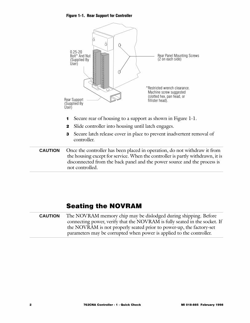
Figure 1-1. Rear Support for Controller
1 Secure rear of housing to a support as shown in Figure 1-1.2 Slide controller into housing until latch engages. 3 Secure latch release cover in place to prevent inadvertent removal of
controller.
CAUTION Once the controller has been placed in operation, do not withdraw it from the housing except for service. When the controller is partly withdrawn, it is disconnected from the back panel and the power source and the process is not controlled.
Seating the NOVRAMCAUTION The NOVRAM memory chip may be dislodged during shipping. Before
connecting power, verify that the NOVRAM is fully seated in the socket. If the NOVRAM is not properly seated prior to power-up, the factory-set parameters may be corrupted when power is applied to the controller.
Rear Support(Supplied ByUser)
0.25-20Bolt* And Nut(Supplied ByUser)
Rear Panel Mounting Screws(2 on each side)
*Restricted wrench clearance. Machine screw suggested (slotted hex, pan head, or fillister head).
2 762CNA Controller - 1 - Quick Check MI 018-885 February 1998
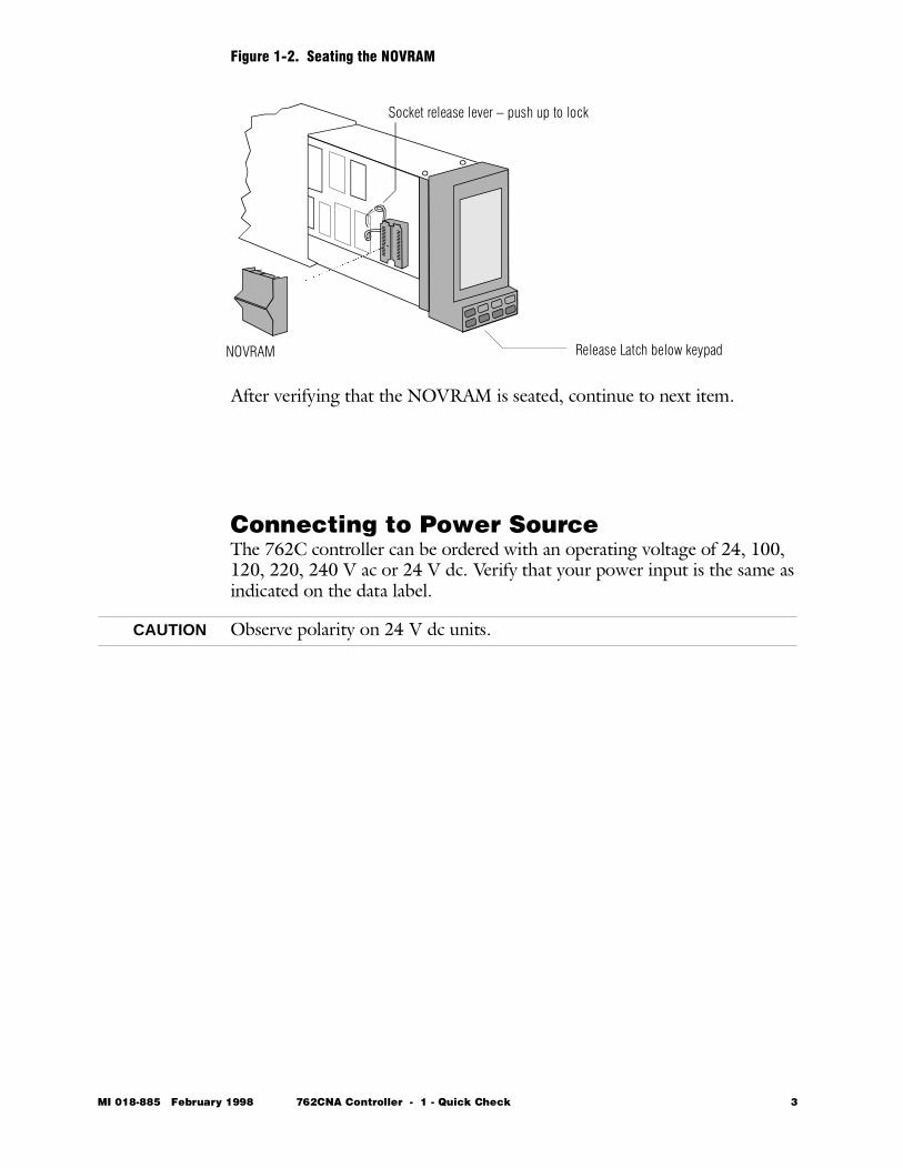
Figure 1-2. Seating the NOVRAM
After verifying that the NOVRAM is seated, continue to next item.
Connecting to Power SourceThe 762C controller can be ordered with an operating voltage of 24, 100, 120, 220, 240 V ac or 24 V dc. Verify that your power input is the same as indicated on the data label.
CAUTION Observe polarity on 24 V dc units.
NOVRAM Release Latch below keypad
Socket release lever – push up to lock
MI 018-885 February 1998 762CNA Controller - 1 - Quick Check 3
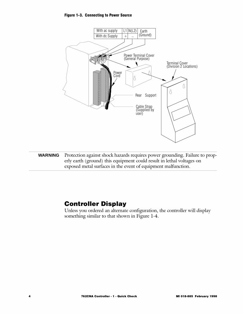
Figure 1-3. Connecting to Power Source
WARNING Protection against shock hazards requires power grounding. Failure to prop-erly earth (ground) this equipment could result in lethal voltages on exposed metal surfaces in the event of equipment malfunction.
Controller DisplayUnless you ordered an alternate configuration, the controller will display something similar to that shown in Figure 1-4.
Power Terminal Cover
PowerCord
With ac supplyWith dc Supply
L1+
N(L2)_
Earth(Ground)
Rear Support
Cable Strap(Supplied byuser)
(General Purpose)Terminal Cover(Division 2 Locations)
4 762CNA Controller - 1 - Quick Check MI 018-885 February 1998
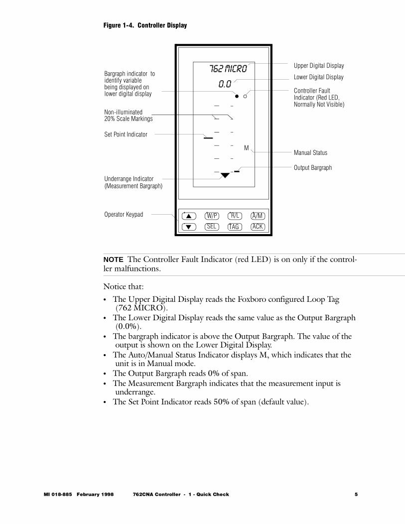
Figure 1-4. Controller Display
NOTE The Controller Fault Indicator (red LED) is on only if the control-ler malfunctions.
Notice that:• The Upper Digital Display reads the Foxboro configured Loop Tag
(762 MICRO).• The Lower Digital Display reads the same value as the Output Bargraph
(0.0%).• The bargraph indicator is above the Output Bargraph. The value of the
output is shown on the Lower Digital Display.• The Auto/Manual Status Indicator displays M, which indicates that the
unit is in Manual mode. • The Output Bargraph reads 0% of span.• The Measurement Bargraph indicates that the measurement input is
underrange.• The Set Point Indicator reads 50% of span (default value).
M
W/P R/L A/M
SEL TAG ACK
Upper Digital Display
Lower Digital Display
Manual Status
Bargraph indicator toidentify variablebeing displayed onlower digital display
Underrange Indicator
Operator Keypad
(Measurement Bargraph)
Set Point Indicator
Output Bargraph
Non-illuminated20% Scale Markings
Controller Fault Indicator (Red LED,Normally Not Visible)
0.0
762 MICRO
MI 018-885 February 1998 762CNA Controller - 1 - Quick Check 5

Changing the DisplayTo check out the panel display and to become familiar with the functions of the keypad (see Figure 1-5), exercise the keys as described below.
Figure 1-5. Operator Keypad
The W/P and R/L keys are configured in the OFF position and are not func-tional at this time. When configured, a W or P and an R or L appear on the display.
Using the A/M Key
The A/M key will transfer the controller between AUTO (A) and MANUAL (M). Try pressing the A/M key. Return to MANUAL before pro-ceeding. Notice that the bargraph indicator always moves over the Output Bargraph when you transfer the controller to Manual and that it moves over the Measurement Bargraph when you transfer to Auto.
Using the SEL Key
Try pressing the SEL key. Note that this causes the Digital Display to show the value for the Set Point Indicator, or the Measurement Bargraph, or the Output Bargraph, depending on the location of the bargraph indicator.
Manual Output
Press the SEL key to move the bargraph indicator to the Output Bargraph. You are now prepared to adjust the controller output and to read the values on the Output Bargraph and the Lower Digital Display.Increase the output by pressing the ∆ key. The Output Bargraph and the Lower Digital Display will read the value you select.To decrease the output, press the ∇ key.If you press/hold either the ∆ or the ∇ key while adjusting the manual out-put, the value changes at an accelerated rate that depends on the duration of the hold.It is not necessary to return the controller to the original values before pro-ceeding to the next step.
Adjusting the Set Point
Press the SEL to move the bargraph indicator over the set point. The Mea-surement and Set Point Indicator engineering unit labels are the same (PCT is factory default). Press the ∆ or ∇ keys to adjust the set point. Note the set point value (shown on the lower display) and its corresponding indicator change (each segment represents a 2% change in the value). Holding the key causes the value to change at a faster rate.
W/P R/L A/M
SEL TAG ACK
6 762CNA Controller - 1 - Quick Check MI 018-885 February 1998
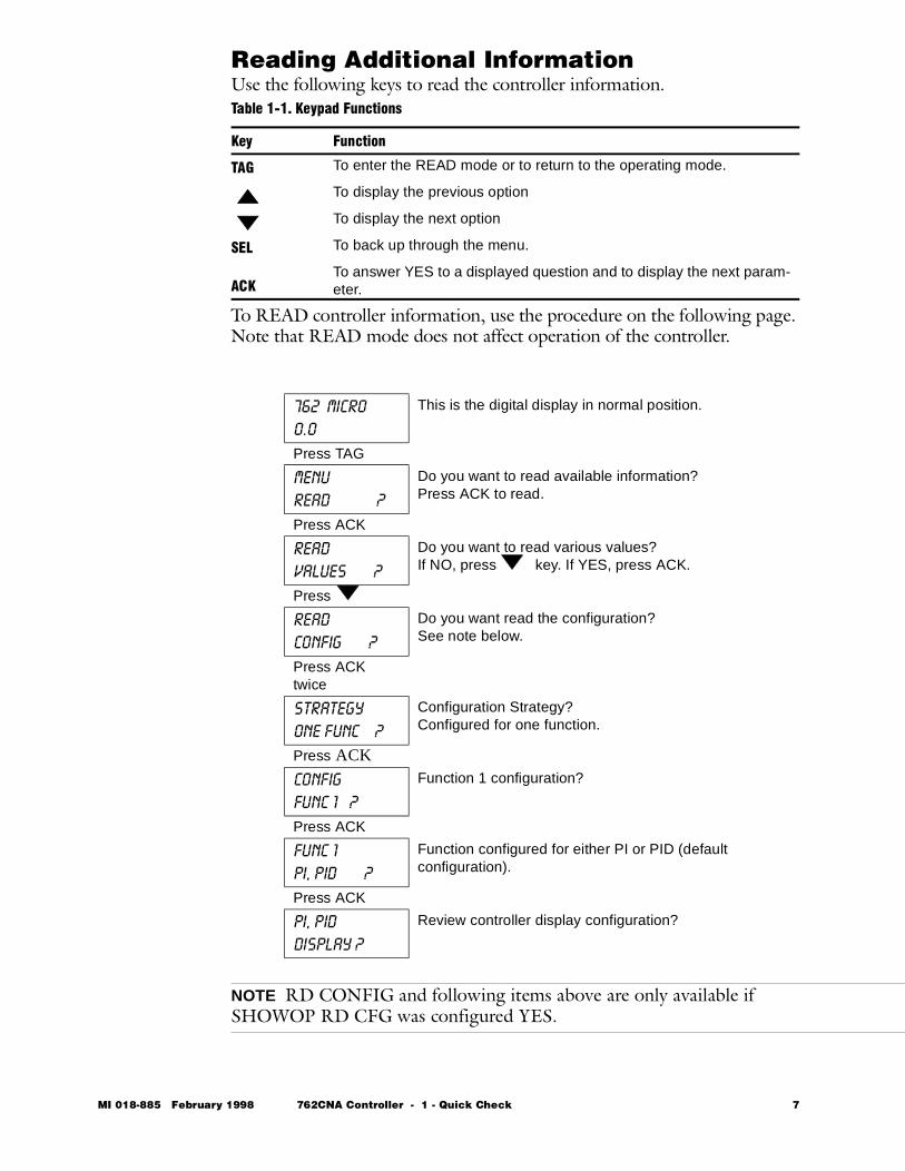
Reading Additional InformationUse the following keys to read the controller information.
To READ controller information, use the procedure on the following page. Note that READ mode does not affect operation of the controller.
NOTE RD CONFIG and following items above are only available if SHOWOP RD CFG was configured YES.
Table 1-1. Keypad Functions
Key Function
TAG To enter the READ mode or to return to the operating mode.
To display the previous option
To display the next option
SEL To back up through the menu.
ACKTo answer YES to a displayed question and to display the next param-eter.
762 MICRO
0.0
This is the digital display in normal position.
Press TAG
MENU
READ ?
Do you want to read available information?Press ACK to read.
Press ACK
READ
VALUES ?
Do you want to read various values?If NO, press key. If YES, press ACK.
Press
READ
CONFIG ?
Do you want read the configuration?See note below.
Press ACK twice
STRATEGY
ONE FUNC ?
Configuration Strategy?Configured for one function.
Press ACK
CONFIG
FUNC 1 ?
Function 1 configuration?
Press ACK
FUNC 1
PI, PID ?
Function configured for either PI or PID (default configuration).
Press ACK
PI, PID
=DISPLAY ?
Review controller display configuration?
MI 018-885 February 1998 762CNA Controller - 1 - Quick Check 7

Reading Additional Information (cont.)You can continue to read by pressing the ACK key. If you want to back up to a previous option, press the SEL key. Pressing the ∇ key repeatedly selects further options.
Return to NORMAL
To return to normal operation at any time, press the TAG key. Note that no changes can be made in the READ mode.This completes the checkout procedure to verify that you have a functional unit as shipped from our factory.
Looking for More Information?For more detailed information, refer to the following sections of this manual:For general installation information, refer to Chapter 3. For dimensional details, refer to Appendix E.For configuration instructions, refer to Chapter 4 and to Appendices B and C.For operating instructions, refer to Chapter 5.For calibration, troubleshooting and maintenance information, refer to Chapter 7. For replacement parts and accessories, refer to the parts list in Appendix D. For information on serial communications programming, refer to MI 018-888, Serial Communication Guide for 762C and 743CB Controllers.For information about specifications and agency certifications, refer to Appendix A. If you need additional help, please call the Foxboro Customer Service Cen-ter at 1-800-441-6014 in the U.S.A. or your local Foxboro representative.
8 762CNA Controller - 1 - Quick Check MI 018-885 February 1998

762C SINGLESTATION
MICROController
February 1998
Preface • xiii Chapter 1 Quick Check • 1
Ð Chapter 2 Product Overview • 11 Chapter 3 Installation • 23 Chapter 4 Configuration • 49 Chapter 5 Operation • 109 Chapter 6 EXACT Tuning • 135 Chapter 7 Calibration, Troubleshooting,
Maintenance • 159 Appendix A Specifications • 183 Appendix B Configuration Worksheets • 193 Appendix C Structure Diagrams • 237 Appendix D Parts List • 247 Appendix E Dimensional Print • 255 Appendix F Functional Diagram • 261 Glossary • 267 Index • 287
The Intelligent Automation People

10 762CNA Controller MI 018-885 February 1998

MI 018-885 Februar
2 Product Overview
This chapter is a summary of the general characteristics of the product. Detailed specifications can be found in Appendix .The chapter is divided into the following parts:• Description • 12 • Functional Block Diagram • 13 • Front Panel • 18 • Keypad Functions • 19
y 1998 762CNA Controller - 2 - Product Overview 11
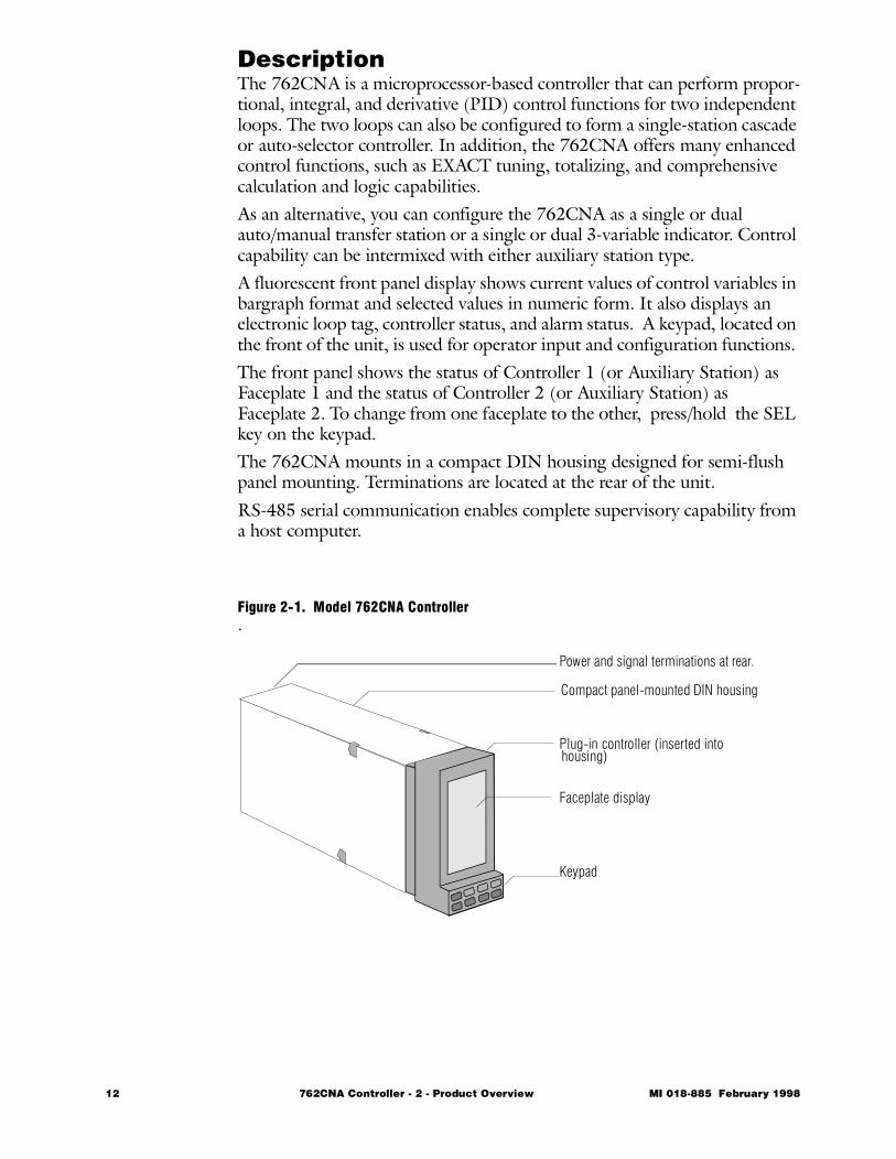
DescriptionThe 762CNA is a microprocessor-based controller that can perform propor-tional, integral, and derivative (PID) control functions for two independent loops. The two loops can also be configured to form a single-station cascade or auto-selector controller. In addition, the 762CNA offers many enhanced control functions, such as EXACT tuning, totalizing, and comprehensive calculation and logic capabilities.As an alternative, you can configure the 762CNA as a single or dual auto/manual transfer station or a single or dual 3-variable indicator. Control capability can be intermixed with either auxiliary station type.A fluorescent front panel display shows current values of control variables in bargraph format and selected values in numeric form. It also displays an electronic loop tag, controller status, and alarm status. A keypad, located on the front of the unit, is used for operator input and configuration functions. The front panel shows the status of Controller 1 (or Auxiliary Station) as Faceplate 1 and the status of Controller 2 (or Auxiliary Station) as Faceplate 2. To change from one faceplate to the other, press/hold the SEL key on the keypad.The 762CNA mounts in a compact DIN housing designed for semi-flush panel mounting. Terminations are located at the rear of the unit.RS-485 serial communication enables complete supervisory capability from a host computer.
Figure 2-1. Model 762CNA Controller.
Compact panel-mounted DIN housing
Plug-in controller (inserted into
Faceplate display
Keypad
housing)
Power and signal terminations at rear.
12 762CNA Controller - 2 - Product Overview MI 018-885 February 1998
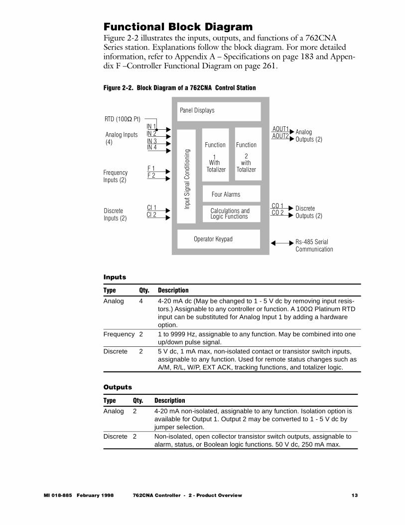
Functional Block Diagram Figure 2-2 illustrates the inputs, outputs, and functions of a 762CNA Series station. Explanations follow the block diagram. For more detailed information, refer to Appendix A – Specifications on page 183 and Appen-dix F –Controller Functional Diagram on page 261.
Figure 2-2. Block Diagram of a 762CNA Control Station
Inputs
Outputs
Type Qty. Description
Analog 4 4-20 mA dc (May be changed to 1 - 5 V dc by removing input resis-tors.) Assignable to any controller or function. A 100Ω Platinum RTD input can be substituted for Analog Input 1 by adding a hardware option.
Frequency 2 1 to 9999 Hz, assignable to any function. May be combined into one up/down pulse signal.
Discrete 2 5 V dc, 1 mA max, non-isolated contact or transistor switch inputs, assignable to any function. Used for remote status changes such as A/M, R/L, W/P, EXT ACK, tracking functions, and totalizer logic.
Type Qty. Description
Analog 2 4-20 mA non-isolated, assignable to any function. Isolation option is available for Output 1. Output 2 may be converted to 1 - 5 V dc by jumper selection.
Discrete 2 Non-isolated, open collector transistor switch outputs, assignable to alarm, status, or Boolean logic functions. 50 V dc, 250 mA max.
1 2
Function
Panel Displays
Function
Inpu
t Sig
nal C
ondi
tioni
ngFour Alarms
Calculations andLogic Functions
Operator Keypad
Analog Inputs (4)
Frequency Inputs (2)
Discrete Inputs (2)
Analog Outputs (2)
Discrete Outputs (2)
Rs-485 Serial Communication
RTD (100Ω Pt)
WithTotalizer Totalizer
with
AOUT1AOUT2
CI 1CI 2
CO 1CO 2
IN 1IN 2IN 3IN 4
F 1F 2
MI 018-885 February 1998 762CNA Controller - 2 - Product Overview 13
Input Signal Conditioning
Alarms
Calculations/Logic Functions
Type Description
Linear The conditioned signal is directly proportional to the input signal.Square Root The conditioned signal is proportional to the square root of the input
signal.Squared The conditioned signal is proportional to the square of the input sig-
nal.Characterizer 1 Signal conditioning modifies the input signal to match the character-
istics of a custom curve entered by the user (8 segments).Characterizer 2 Signal conditioning modifies the input signal to match the character-
istics of a second custom curve entered by the user (8 segments).Thermocouple (Transmitter)
Signal conditioning linearizes the display to match the characteris-tics of a standard thermocouple type (E, J, or K). For display pur-poses only.
RTD Signal conditioning linearizes the display to match the characteris-tics of a standard RTD type (IEC 100 or SAMA 100). For display purposes only.
Input Filter A second-order Butterworth filter may be assigned to any input.
Item Description
Quantity Four, assignable to any input or output signal or internal variable.Type 2-level (high/high, low/low, or high/low) with adjustable deadband.Form Can be configured to activate on Absolute Value, Deviation from a ref-
erence value, or Rate-of Change of a variable.Action Latching, nonlatching, or permissive. (Latching alarms require opera-
tor acknowledgment. Nonlatching alarms may be acknowledged but are self clearing when the alarm condition no longer exists. Permis-sive alarms do not require acknowledgment.)
Calculation Description
Boolean Logic Five single and five dual gates are available for logic computation. Each gate is configured by first selecting the logic and then selecting the source of each input. Inputs may be contact inputs, alarm output states, status indicator outputs, EXACT state, gate outputs, or three fixed states. (Refer to Table 4-3, Gate Input List, on page 53.) Gates 0 through 4 are single input gates user-configured as DIRECT or NOT (inverse logic). Gates 5 through 9 are dual input gates, each of which can be defined as: OR, NOR, AND, NAND, XOR, or XNOR.
Dynamic Compensation
Lead/lag, impulse, and deadtime calculations with user-adjustable Gain, Input Bias, Out Bias, and Deadtime.The result of a dedicated calculation function can be passed through a dynamic compensator, prior to signal distribution. The dynamic compensator provides lead/lag with an impulse option, and dead time functions, each with its individual follow switch. Functionally, dead time precedes lead/lag.Using the dynamic compensator and the follow switches, you can implement feedforward and other complex control applications easily and efficiently.
14 762CNA Controller - 2 - Product Overview MI 018-885 February 1998
Controller Selections (Functions 1 and 2)
Algebraic The 762CNA can perform up to three independent algebraic calcula-tions. Each may contain up to nine characters. The variables may include results of other calculation blocks, scaled and conditioned inputs, and other internal control signals. To configure an equation, enter one character at a time from the keypad, following the usual rules of algebra, and a few easy-to-learn rules.
Type Description
PID Proportional (P), Integral (I), and Derivative (D) algorithm is standard for both controllers. May be configured as P, I, PD, PI, or PID.
EXACT EXACT control, the Foxboro patented adaptive tuning system, is available on both control loops, subject to totalizer configuration con-straints.
Cascade With this configuration, the output of Controller 1 is the set point of Controller 2. Allows bumpless transfer between auto/manual and between remote/local set point modes.
Batch Either or both controllers can be configured for batch control, which prevents controller windup when the controlled process is shut down.
Auto Selector
The two controllers can be combined to provide a single auto-selected output that can be used for constraint or dual mode control. The choice of lower, higher, or logic-selected output is available. Feed-back signals prevent controller windup. You can configure one com-mon or two independent auto/manual functions.
Split Range The two 4-20 mA outputs can be driven from a single controller. This allows one measured variable to be controlled by two manipulated variables. A typical application is a temperature control system in which both the heating medium and the cooling medium are manipu-lated.
Remote or Local Setpoints
The set points of both controllers may be adjusted manually from the front panel keypad or automatically from a remote device. Each remote set point can be sourced to any signal in the Signal Distribu-tion List (see Table 4-2). The R/L key toggles between remote and local set point modes.
Panel or Workstation
Supervision of the controller can be local (Panel) or remote (Worksta-tion).
Other Nonlinear extender, measurement and set point tracking, output track-ing, output multiplication or summing, external feedback, external out-put limits. Dynamic compensation (lead/lag, impulse, deadtime) provides a capability for implementing feedforward and other advanced control algorithms. Bypass of the control algorithm by enabling the set point to manipulate the output directly.
Calculation Description
MI 018-885 February 1998 762CNA Controller - 2 - Product Overview 15
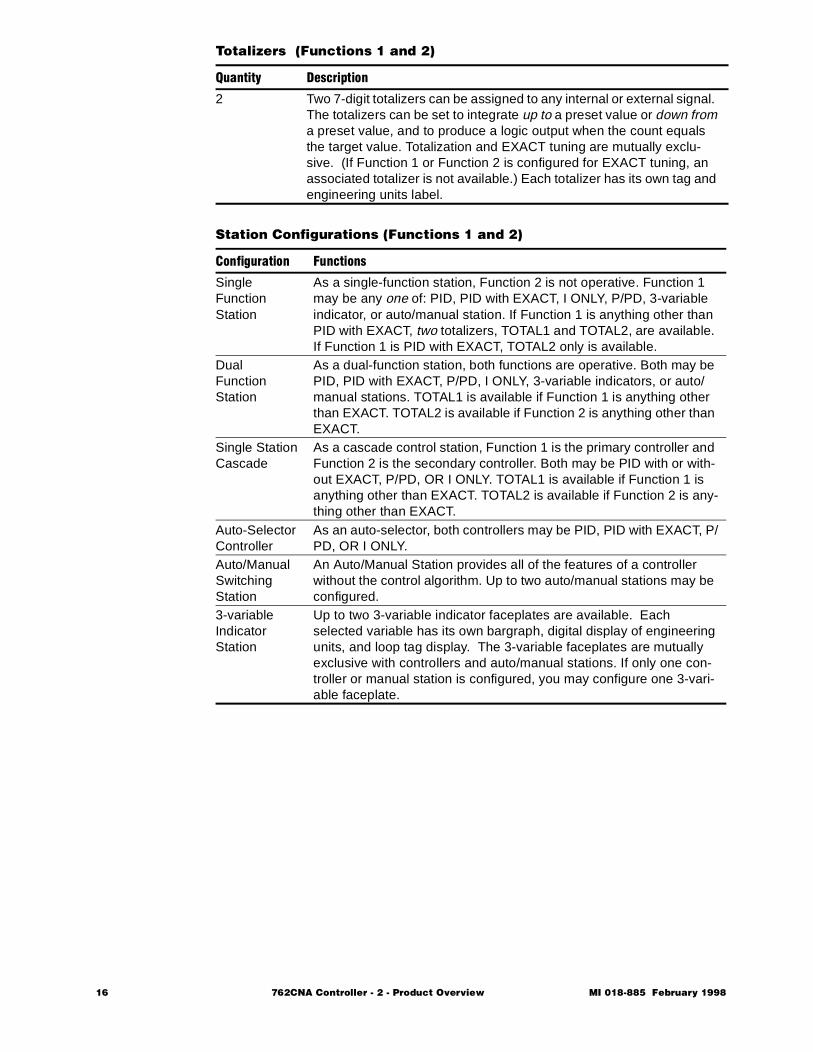
Totalizers (Functions 1 and 2)
Station Configurations (Functions 1 and 2)
Quantity Description
2 Two 7-digit totalizers can be assigned to any internal or external signal. The totalizers can be set to integrate up to a preset value or down from a preset value, and to produce a logic output when the count equals the target value. Totalization and EXACT tuning are mutually exclu-sive. (If Function 1 or Function 2 is configured for EXACT tuning, an associated totalizer is not available.) Each totalizer has its own tag and engineering units label.
Configuration Functions
SingleFunction Station
As a single-function station, Function 2 is not operative. Function 1 may be any one of: PID, PID with EXACT, I ONLY, P/PD, 3-variable indicator, or auto/manual station. If Function 1 is anything other than PID with EXACT, two totalizers, TOTAL1 and TOTAL2, are available. If Function 1 is PID with EXACT, TOTAL2 only is available.
Dual Function Station
As a dual-function station, both functions are operative. Both may be PID, PID with EXACT, P/PD, I ONLY, 3-variable indicators, or auto/manual stations. TOTAL1 is available if Function 1 is anything other than EXACT. TOTAL2 is available if Function 2 is anything other than EXACT.
Single Station Cascade
As a cascade control station, Function 1 is the primary controller and Function 2 is the secondary controller. Both may be PID with or with-out EXACT, P/PD, OR I ONLY. TOTAL1 is available if Function 1 is anything other than EXACT. TOTAL2 is available if Function 2 is any-thing other than EXACT.
Auto-Selector Controller
As an auto-selector, both controllers may be PID, PID with EXACT, P/PD, OR I ONLY.
Auto/Manual Switching Station
An Auto/Manual Station provides all of the features of a controller without the control algorithm. Up to two auto/manual stations may be configured.
3-variable Indicator Station
Up to two 3-variable indicator faceplates are available. Each selected variable has its own bargraph, digital display of engineering units, and loop tag display. The 3-variable faceplates are mutually exclusive with controllers and auto/manual stations. If only one con-troller or manual station is configured, you may configure one 3-vari-able faceplate.
16 762CNA Controller - 2 - Product Overview MI 018-885 February 1998
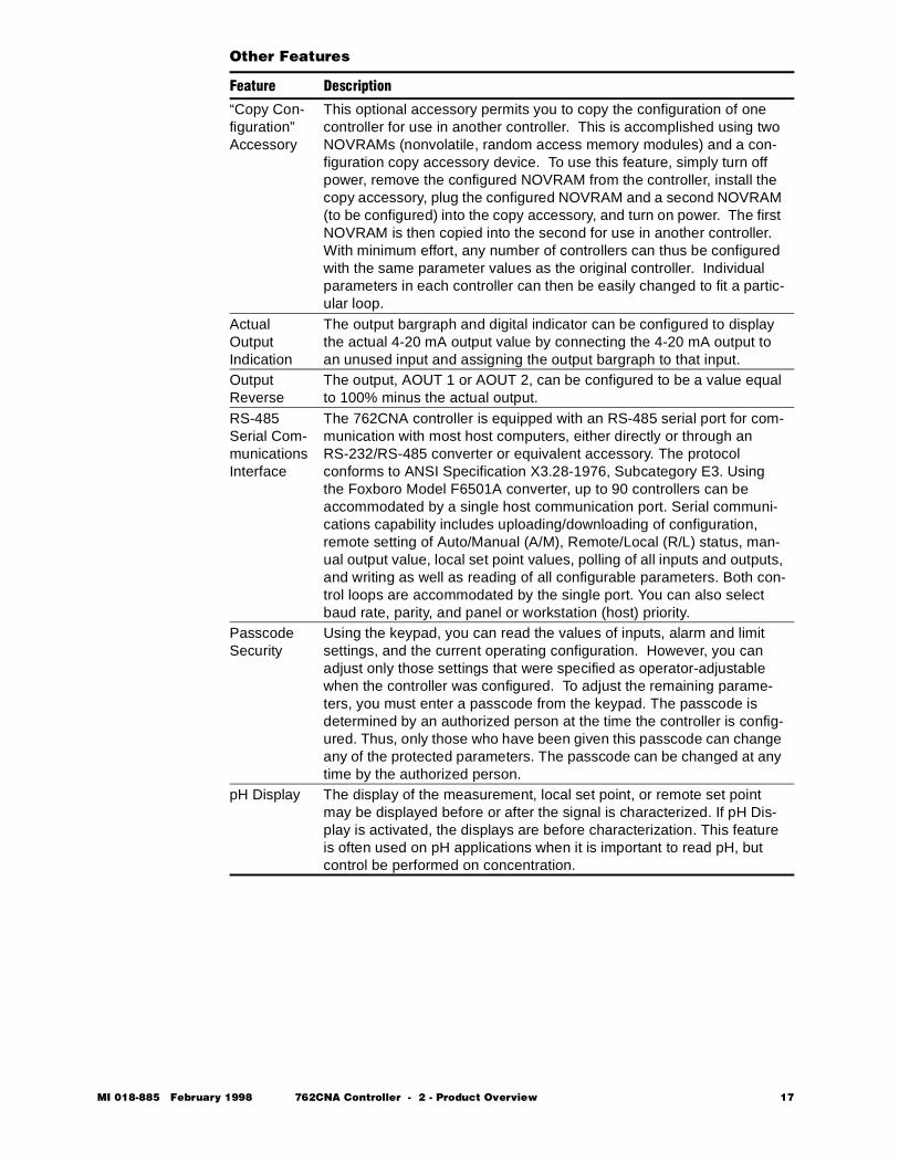
Other Features
Feature Description
“Copy Con-figuration” Accessory
This optional accessory permits you to copy the configuration of one controller for use in another controller. This is accomplished using two NOVRAMs (nonvolatile, random access memory modules) and a con-figuration copy accessory device. To use this feature, simply turn off power, remove the configured NOVRAM from the controller, install the copy accessory, plug the configured NOVRAM and a second NOVRAM (to be configured) into the copy accessory, and turn on power. The first NOVRAM is then copied into the second for use in another controller. With minimum effort, any number of controllers can thus be configured with the same parameter values as the original controller. Individual parameters in each controller can then be easily changed to fit a partic-ular loop.
Actual OutputIndication
The output bargraph and digital indicator can be configured to display the actual 4-20 mA output value by connecting the 4-20 mA output to an unused input and assigning the output bargraph to that input.
Output Reverse
The output, AOUT 1 or AOUT 2, can be configured to be a value equal to 100% minus the actual output.
RS-485 Serial Com-munications Interface
The 762CNA controller is equipped with an RS-485 serial port for com-munication with most host computers, either directly or through an RS-232/RS-485 converter or equivalent accessory. The protocol conforms to ANSI Specification X3.28-1976, Subcategory E3. Using the Foxboro Model F6501A converter, up to 90 controllers can be accommodated by a single host communication port. Serial communi-cations capability includes uploading/downloading of configuration, remote setting of Auto/Manual (A/M), Remote/Local (R/L) status, man-ual output value, local set point values, polling of all inputs and outputs, and writing as well as reading of all configurable parameters. Both con-trol loops are accommodated by the single port. You can also select baud rate, parity, and panel or workstation (host) priority.
Passcode Security
Using the keypad, you can read the values of inputs, alarm and limit settings, and the current operating configuration. However, you can adjust only those settings that were specified as operator-adjustable when the controller was configured. To adjust the remaining parame-ters, you must enter a passcode from the keypad. The passcode is determined by an authorized person at the time the controller is config-ured. Thus, only those who have been given this passcode can change any of the protected parameters. The passcode can be changed at any time by the authorized person.
pH Display The display of the measurement, local set point, or remote set point may be displayed before or after the signal is characterized. If pH Dis-play is activated, the displays are before characterization. This feature is often used on pH applications when it is important to read pH, but control be performed on concentration.
MI 018-885 February 1998 762CNA Controller - 2 - Product Overview 17
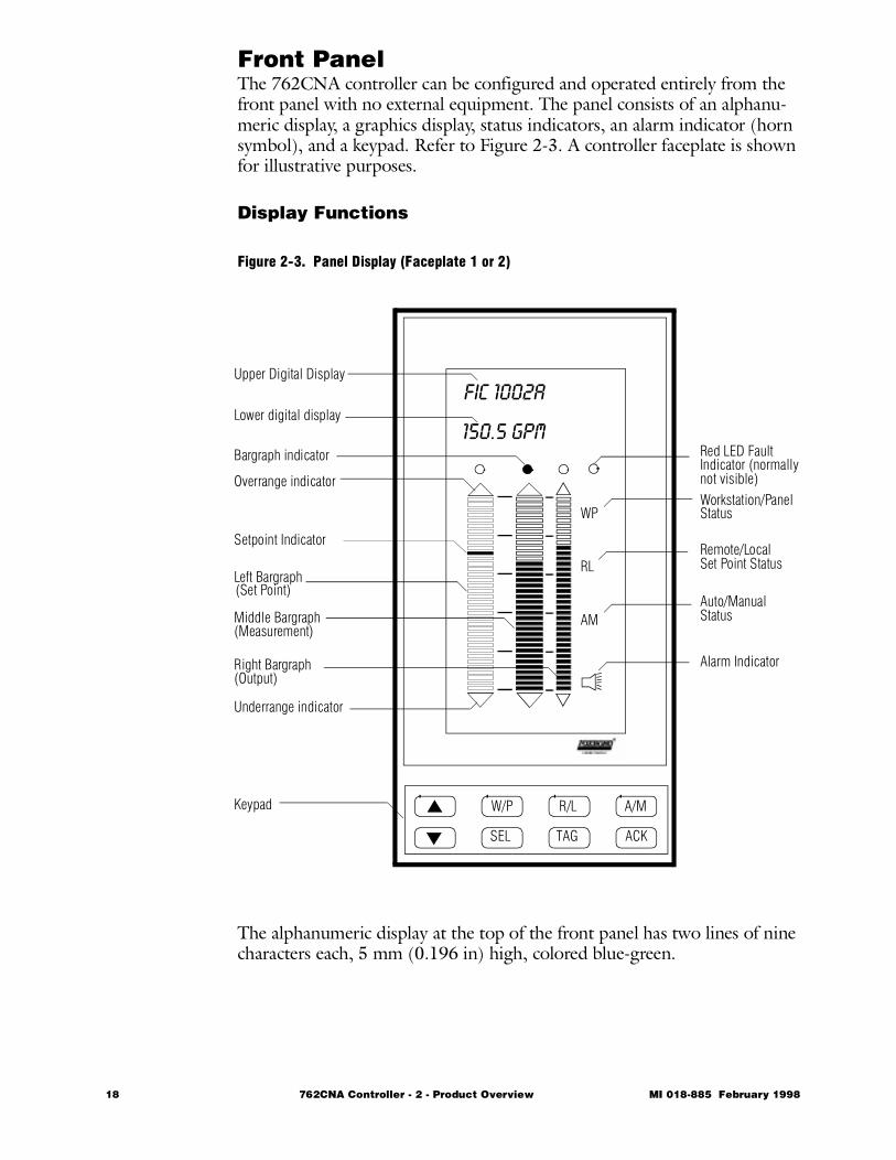
Front PanelThe 762CNA controller can be configured and operated entirely from the front panel with no external equipment. The panel consists of an alphanu-meric display, a graphics display, status indicators, an alarm indicator (horn symbol), and a keypad. Refer to Figure 2-3. A controller faceplate is shown for illustrative purposes.
Display Functions
Figure 2-3. Panel Display (Faceplate 1 or 2)
The alphanumeric display at the top of the front panel has two lines of nine characters each, 5 mm (0.196 in) high, colored blue-green.
WP
RL
AM
FIC 1002A
150.5 GPM
W/P R/L A/M
SEL TAG ACK
Overrange indicator
Upper Digital Display
Lower digital display
Bargraph indicator
Underrange indicator
Left Bargraph
Middle Bargraph
Right Bargraph
Workstation/Panel
Remote/Local
Auto/Manual
Alarm Indicator
Set Point Status
Status
Red LED FaultIndicator (normally
Keypad
Status
(Set Point)
(Measurement)
(Output)
not visible)
Setpoint Indicator
18 762CNA Controller - 2 - Product Overview MI 018-885 February 1998
Display Functions (cont.)The graphics display consists of three bargraphs, each having 50 segments (each 2% of full scale) plus a triangular pointer on top and bottom to indi-cate when the variable is either above or below the range of the display. The bars are 55.4 mm (2.18 in) long. The left and center bargraphs are 5 mm (0.196 in) wide, and the right bar graph is 2.5 mm (0.098 in). All are col-ored blue-green.The status characters (W/P, R/L, A/M) are 4 mm (0.157 in) high; the alarm symbol is 5 mm (0.196 in) high. The status characters are colored blue-green; the alarm symbol is red. The position of the bargraph indicator or “dot” identifies which variable is currently displayed on the Lower Digital Display. To move the indicator to the next position, press (short press) the SEL button.
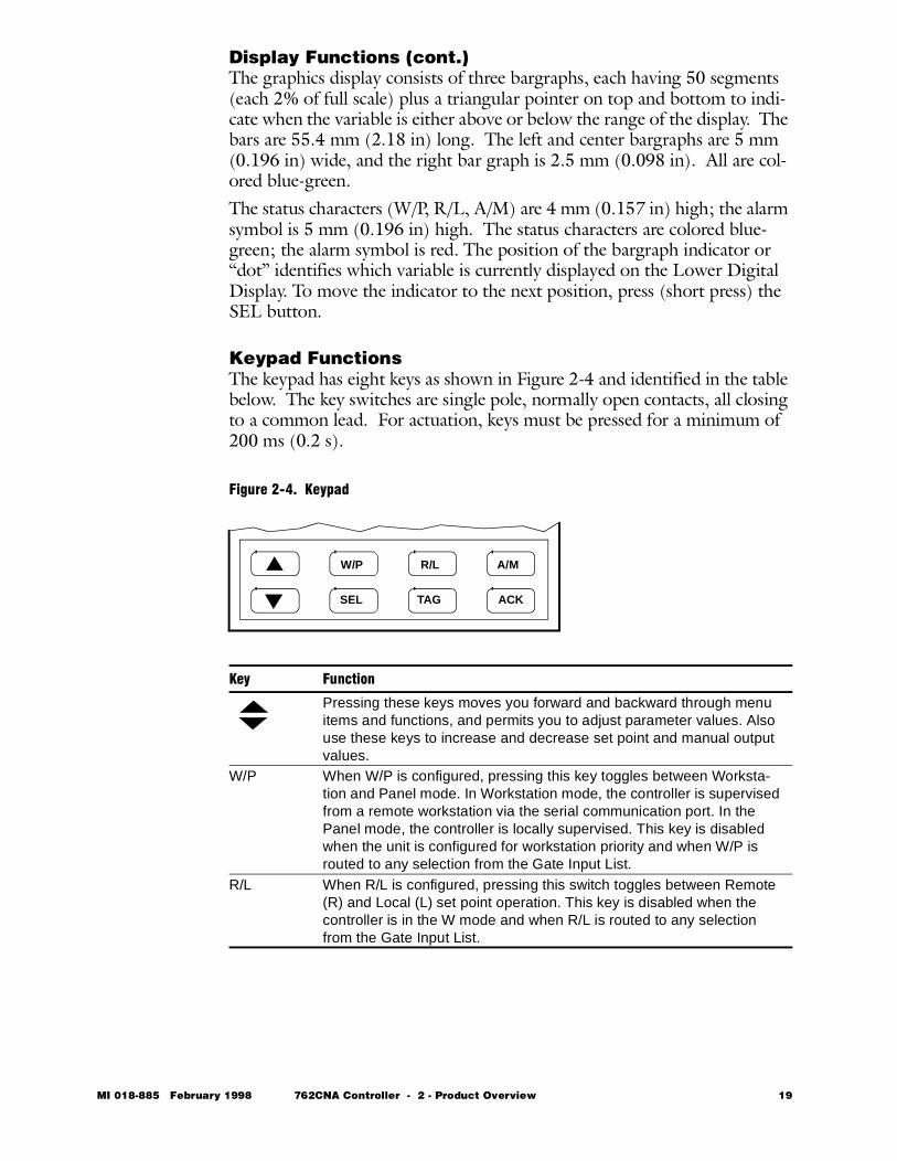
Keypad FunctionsThe keypad has eight keys as shown in Figure 2-4 and identified in the table below. The key switches are single pole, normally open contacts, all closing to a common lead. For actuation, keys must be pressed for a minimum of 200 ms (0.2 s).
Figure 2-4. Keypad
Key Function
Pressing these keys moves you forward and backward through menu items and functions, and permits you to adjust parameter values. Also use these keys to increase and decrease set point and manual output values.
W/P When W/P is configured, pressing this key toggles between Worksta-tion and Panel mode. In Workstation mode, the controller is supervised from a remote workstation via the serial communication port. In the Panel mode, the controller is locally supervised. This key is disabled when the unit is configured for workstation priority and when W/P is routed to any selection from the Gate Input List.
R/L When R/L is configured, pressing this switch toggles between Remote (R) and Local (L) set point operation. This key is disabled when the controller is in the W mode and when R/L is routed to any selection from the Gate Input List.
W/P R/L A/M
SEL TAG ACK
MI 018-885 February 1998 762CNA Controller - 2 - Product Overview 19
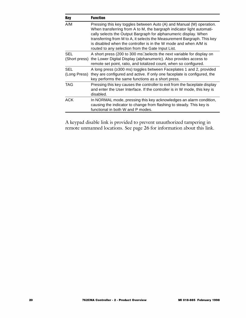
A keypad disable link is provided to prevent unauthorized tampering in remote unmanned locations. See page 26 for information about this link.
A/M Pressing this key toggles between Auto (A) and Manual (M) operation. When transferring from A to M, the bargraph indicator light automati-cally selects the Output Bargraph for alphanumeric display. When transferring from M to A, it selects the Measurement Bargraph. This key is disabled when the controller is in the W mode and when A/M is routed to any selection from the Gate Input List.
SEL(Short press)
A short press (200 to 300 ms) selects the next variable for display on the Lower Digital Display (alphanumeric). Also provides access to remote set point, ratio, and totalized count, when so configured.
SEL(Long Press)
A long press (≥300 ms) toggles between Faceplates 1 and 2, provided they are configured and active. If only one faceplate is configured, the key performs the same functions as a short press.
TAG Pressing this key causes the controller to exit from the faceplate display and enter the User Interface. If the controller is in W mode, this key is disabled.
ACK In NORMAL mode, pressing this key acknowledges an alarm condition, causing the indicator to change from flashing to steady. This key is functional in both W and P modes.
Key Function
20 762CNA Controller - 2 - Product Overview MI 018-885 February 1998

762C SINGLESTATION
MICROController
February 1998
Preface • xiii Chapter 1 Quick Check • 1 Chapter 2 Product Overview • 11
Ð Chapter 3 Installation • 23 Chapter 4 Configuration • 49 Chapter 5 Operation • 109 Chapter 6 EXACT Tuning • 135 Chapter 7 Calibration, Troubleshooting,
Maintenance • 159 Appendix A Specifications • 183 Appendix B Configuration Worksheets • 193 Appendix C Structure Diagrams • 237 Appendix D Parts List • 247 Appendix E Dimensional Print • 255 Appendix F Functional Diagram • 261 Glossary • 267 Index • 287
The Intelligent Automation People

22 762CNA Controller MI 018-885 February 1998

MI 018-885 Februar
3 Installation
This chapter provides all information necessary for installing the controller. It is divided into the following major sections:• Important Safety Precautions • 24 • Unpacking • 24 • Controller Identification • 25 • Positioning Links • 26 • Installation Procedure • 27 • Signal Wiring Guidelines • 30 • Input Signal Wiring • 32 • Output Signal Wiring • 38 • Serial Communication Wiring • 39 • Power Wiring • 40 • Accessory Equipment • 41
y 1998 762CNA Controller - 3 - Installation 23
Important Safety Precautions
Shock HazardsThis product operates from hazardous voltage power sources. Hazardous voltage points are labeled and/or covered within the enclosure. For your own safety, please observe these warnings and replace all protective covers after servicing.
Explosion HazardsCertain versions of this product are designed for use in Class I, Division 2 hazardous locations. If you have one of these versions, never connect or dis-connect power wiring or field wiring unless the area is known to be nonhaz-ardous. Doing this in the presence of an explosive gas-air mixture could result in an explosion.
Unpacking1 Remove the controller from its shipping container and check for
visible damage. 2 Remove the mounting brackets.3 Save the container until you determine that no shipping damage has
occurred. 4 If no damage is observed, proceed with installation. 5 If the controller has been damaged, notify the carrier immediately
and request an inspection report. Obtain a signed copy of the report from the carrier and contact Foxboro in the U.S.A. (Dept. 880 at 1-800-441-6014) or your local Foxboro representative.
24 762CNA Controller - 3 - Installation MI 018-885 February 1998
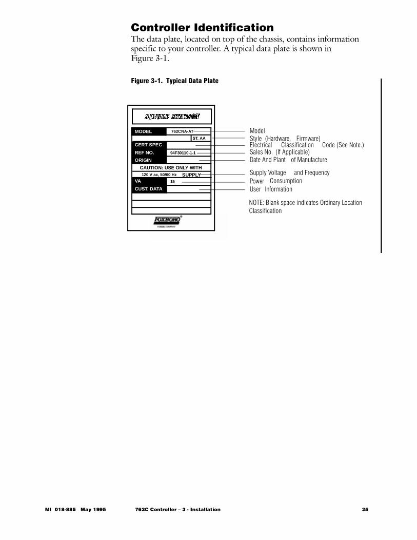
Controller IdentificationThe data plate, located on top of the chassis, contains information specific to your controller. A typical data plate is shown inFigure 3-1.
Figure 3-1. Typical Data Plate
ModelStyle (Hardware, Firmware)Electrical Classification Code (See Note.)Sales No. (If Applicable)Date And Plant of Manufacture
Supply Voltage and FrequencyPower ConsumptionUser Information
762CNA-AT
ST. AA
94F30110-1-1
CAUTION: USE ONLY WITH
SUPPLY120 V ac, 50/60 Hz
15
MODEL
CERT SPEC
REF NO.
ORIGIN
VA
CUST. DATA
NOTE: Blank space indicates Ordinary LocationClassification
MI 018-885 May 1995 762C Controller – 3 - Installation 25
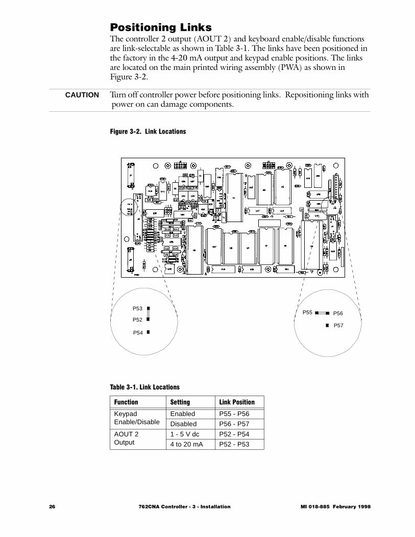
Positioning LinksThe controller 2 output (AOUT 2) and keyboard enable/disable functions are link-selectable as shown in Table 3-1. The links have been positioned in the factory in the 4-20 mA output and keypad enable positions. The links are located on the main printed wiring assembly (PWA) as shown inFigure 3-2.
CAUTION Turn off controller power before positioning links. Repositioning links with power on can damage components.
Figure 3-2. Link Locations
Table 3-1. Link Locations
Function Setting Link Position
KeypadEnable/Disable
Enabled P55 - P56
Disabled P56 - P57
AOUT 2Output
1 - 5 V dc P52 - P54
4 to 20 mA P52 - P53
P53
P52
P54
P56P55
P57
26 762CNA Controller - 3 - Installation MI 018-885 February 1998
Installation ProcedureThe controller is shipped in its housing, which mounts in a DIN panel cut-out. For exact cutout dimensions, refer to the Dimensional Print in Appendix E.
NOTE If you plan to use 1-5 V dc instead of 4-20 mA on some inputs, you will have to remove the 250Ω resistors across the selected input termi-nals. Although it is usually more convenient to do this before installing the housing in the panel, you may also do it after installation. Refer to “Removing Input Range Resistors” on page 29 for instructions.
CAUTION Be sure that installation complies with all applicable codes, safety regula-tions, and certification requirements. For product safety specifications, refer to Table A-4 on page 187.
The installation procedure is as follows:
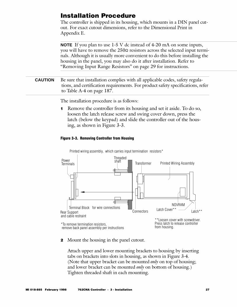
1 Remove the controller from its housing and set it aside. To do so, loosen the latch release screw and swing cover down, press the latch (below the keypad) and slide the controller out of the hous-ing, as shown in Figure 3-3.
Figure 3-3. Removing Controller from Housing
2 Mount the housing in the panel cutout.
Attach upper and lower mounting brackets to housing by inserting tabs on brackets into slots in housing, as shown in Figure 3-4. (Note that upper bracket can be mounted only on top of housing; and lower bracket can be mounted only on bottom of housing.) Tighten threaded shaft in each mounting.
NOVRAM
Latch**
**Loosen cover with screwdriver.
Transformer Printed Wiring AssemblyPowerTerminals
Printed wiring assembly, which carries input termination
ConnectorsTerminal Block for wire connections
Rear Supportand cable restraint
resistors*
Threadedshaft
*To remove termination resistors, remove back panel assembly per instructions
Press latch to release controller from housing.
Latch Cover**
MI 018-885 February 1998 762CNA Controller - 3 - Installation 27
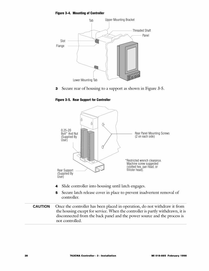
Figure 3-4. Mounting of Controller
3 Secure rear of housing to a support as shown in Figure 3-5.
Figure 3-5. Rear Support for Controller
4 Slide controller into housing until latch engages. 5 Secure latch release cover in place to prevent inadvertent removal of
controller.
CAUTION Once the controller has been placed in operation, do not withdraw it from the housing except for service. When the controller is partly withdrawn, it is disconnected from the back panel and the power source and the process is not controlled.
Panel
Lower Mounting Tab
Threaded Shaft
Upper Mounting BracketTab
SlotFlange
Rear Support(Supplied ByUser)
0.25-20Bolt* And Nut(Supplied ByUser)
Rear Panel Mounting Screws(2 on each side)
*Restricted wrench clearance. Machine screw suggested (slotted hex, pan head, or fillister head).
28 762CNA Controller - 3 - Installation MI 018-885 February 1998
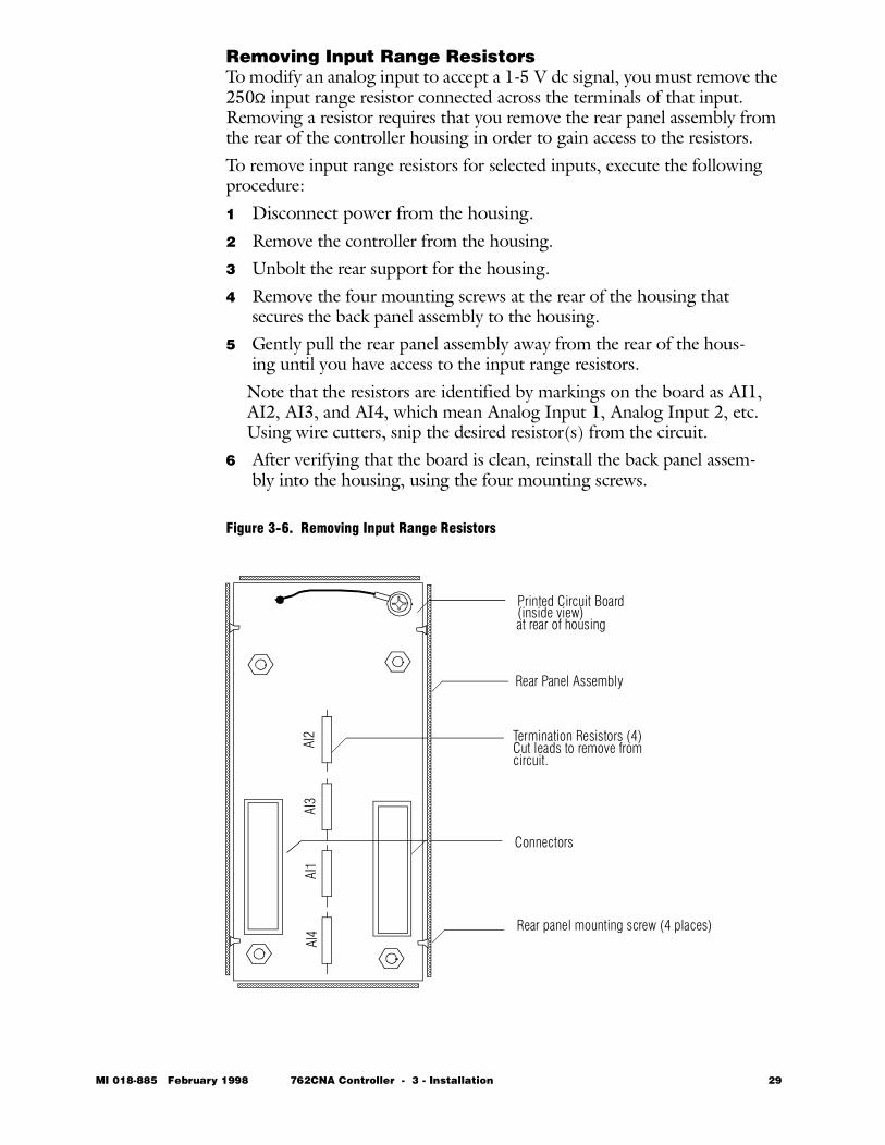
Removing Input Range ResistorsTo modify an analog input to accept a 1-5 V dc signal, you must remove the 250Ω input range resistor connected across the terminals of that input. Removing a resistor requires that you remove the rear panel assembly from the rear of the controller housing in order to gain access to the resistors. To remove input range resistors for selected inputs, execute the following procedure:1 Disconnect power from the housing.2 Remove the controller from the housing.3 Unbolt the rear support for the housing.4 Remove the four mounting screws at the rear of the housing that
secures the back panel assembly to the housing.5 Gently pull the rear panel assembly away from the rear of the hous-
ing until you have access to the input range resistors.Note that the resistors are identified by markings on the board as AI1, AI2, AI3, and AI4, which mean Analog Input 1, Analog Input 2, etc. Using wire cutters, snip the desired resistor(s) from the circuit.
6 After verifying that the board is clean, reinstall the back panel assem-bly into the housing, using the four mounting screws.
Figure 3-6. Removing Input Range Resistors
AI4
AI1
AI3
AI2 Termination Resistors (4)
Cut leads to remove fromcircuit.
Printed Circuit Board
at rear of housing(inside view)
Connectors
Rear Panel Assembly
Rear panel mounting screw (4 places)
MI 018-885 February 1998 762CNA Controller - 3 - Installation 29
Removing Input Range Resistors (cont.)
7 Bolt the housing to the rear mounting support.8 Slide the controller back into the housing, secure the latch release
cover, and re-connect power.
Signal Wiring GuidelinesCAUTION Except for the 4 to 20 mA isolated output module, all inputs, outputs, and
the transmitter power supply share a non-isolated, common, ungrounded reference line. This line will be normally connected to plant ground (or some other reference point) by external wiring schemes adopted by plant practices. In doing this, care must be exercised that such grounding shall only occur at a single point, and by single connection of “common” to the designated reference point (plant ground).
CAUTION Multiple connections of “common” lines to various grounding locations will result in ground loops and give rise to faulty unit operation. Similar prob-lems will occur if multiple grounding is made both at the 762CNA and at the receiver/transmitter locations.
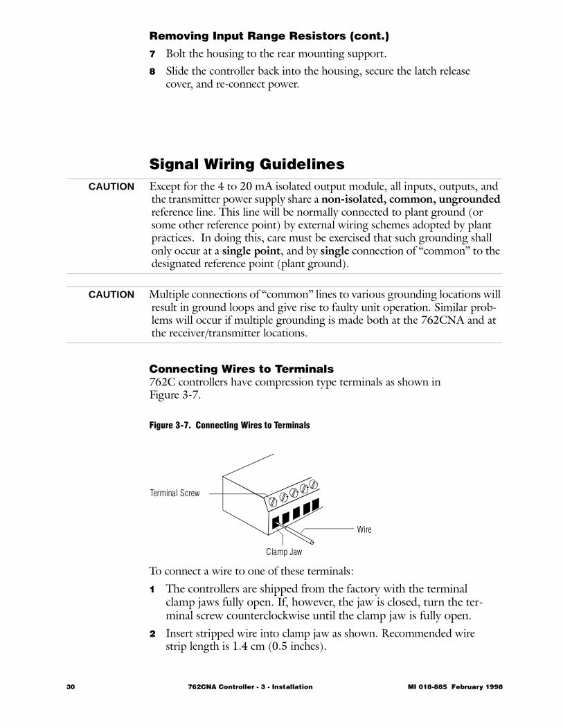
Connecting Wires to Terminals762C controllers have compression type terminals as shown inFigure 3-7.
Figure 3-7. Connecting Wires to Terminals
To connect a wire to one of these terminals:
1 The controllers are shipped from the factory with the terminal clamp jaws fully open. If, however, the jaw is closed, turn the ter-minal screw counterclockwise until the clamp jaw is fully open.
2 Insert stripped wire into clamp jaw as shown. Recommended wire strip length is 1.4 cm (0.5 inches).
Wire
Clamp Jaw
Terminal Screw
30 762CNA Controller - 3 - Installation MI 018-885 February 1998
Connecting Wires to Terminals (cont.)
3 Turn terminal screw clockwise to tighten clamp. 4 Verify that clamp grips only the metal wire and not the insulation.
Also verify that the wire is secured in place after tightening clamp. Recommended installation torque is 3.39 to 5.42 N-m (2.5 to 4.0 lb-in).
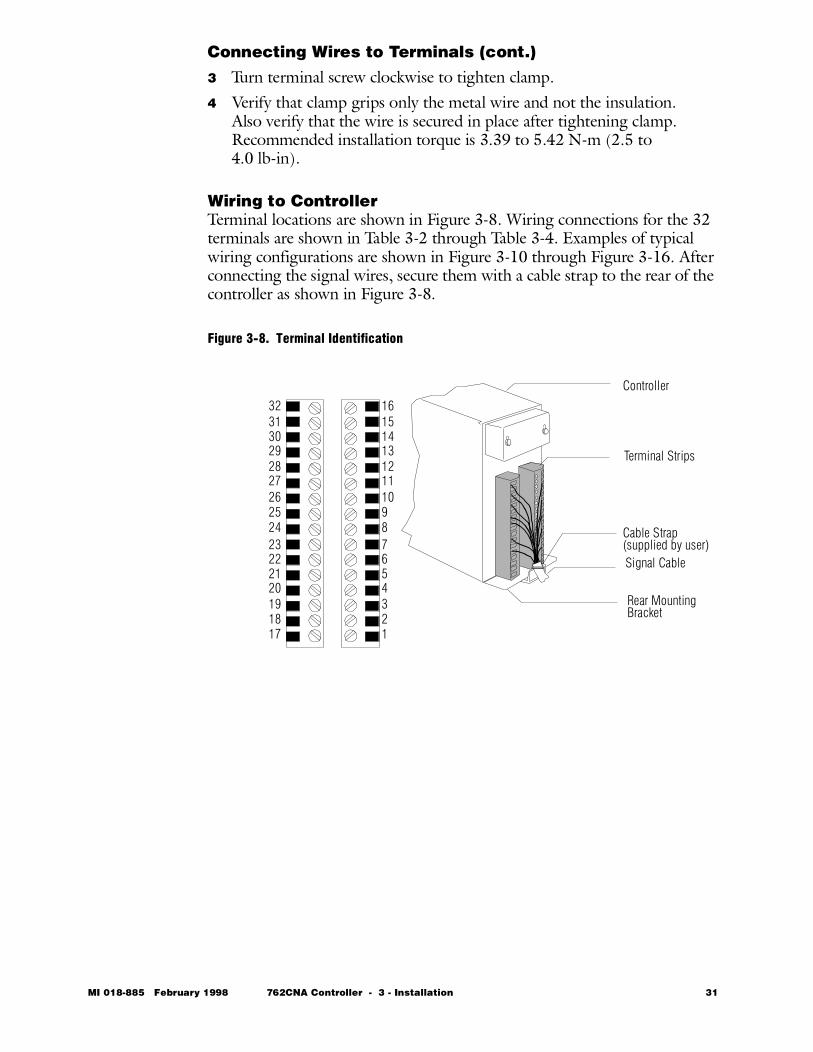
Wiring to ControllerTerminal locations are shown in Figure 3-8. Wiring connections for the 32 terminals are shown in Table 3-2 through Table 3-4. Examples of typical wiring configurations are shown in Figure 3-10 through Figure 3-16. After connecting the signal wires, secure them with a cable strap to the rear of the controller as shown in Figure 3-8.
Figure 3-8. Terminal Identification
Controller
Cable Strap
Signal Cable
Rear Mounting
(supplied by user)
1
1615141312111098765432
17
323130292827262524232221201918 Bracket
Terminal Strips
MI 018-885 February 1998 762CNA Controller - 3 - Installation 31
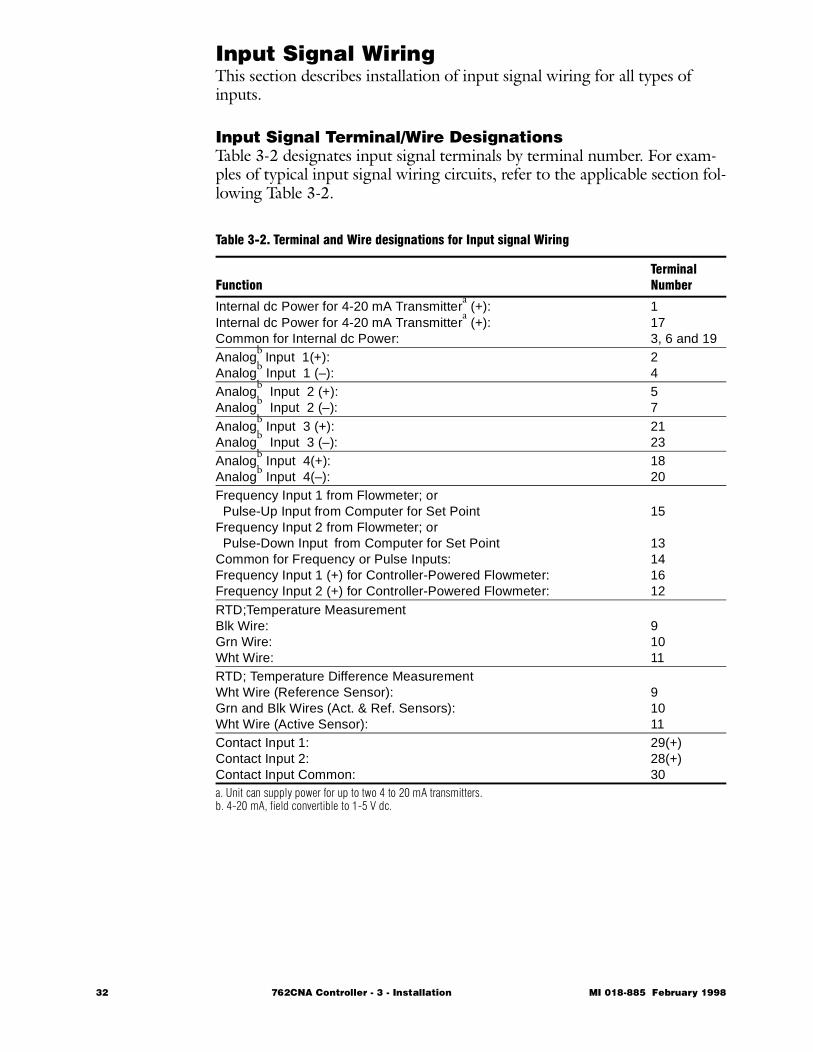
Input Signal WiringThis section describes installation of input signal wiring for all types of inputs.
Input Signal Terminal/Wire Designations Table 3-2 designates input signal terminals by terminal number. For exam-ples of typical input signal wiring circuits, refer to the applicable section fol-lowing Table 3-2.
Table 3-2. Terminal and Wire designations for Input signal Wiring
FunctionTerminal Number
Internal dc Power for 4-20 mA Transmittera (+):
Internal dc Power for 4-20 mA Transmittera (+):
Common for Internal dc Power:
1173, 6 and 19
Analogb
Input 1(+):Analog
b Input 1 (–):
24
Analogb Input 2 (+):
Analogb Input 2 (–):
57
Analogb Input 3 (+):
Analogb Input 3 (–):
2123
Analogb Input 4(+):
Analogb Input 4(–):
1820
Frequency Input 1 from Flowmeter; or Pulse-Up Input from Computer for Set PointFrequency Input 2 from Flowmeter; or Pulse-Down Input
from Computer for Set Point
Common for Frequency or Pulse Inputs:Frequency Input 1 (+) for Controller-Powered Flowmeter:Frequency Input 2 (+) for Controller-Powered Flowmeter:
15
13141612
RTD;Temperature MeasurementBlk Wire:Grn Wire:Wht Wire:
91011
RTD; Temperature Difference MeasurementWht Wire (Reference Sensor):Grn and Blk Wires (Act. & Ref. Sensors):Wht Wire (Active Sensor):
91011
Contact Input 1:Contact Input 2:Contact Input Common:
29(+)28(+)30
a. Unit can supply power for up to two 4 to 20 mA transmitters.b. 4-20 mA, field convertible to 1-5 V dc.
32 762CNA Controller - 3 - Installation MI 018-885 February 1998
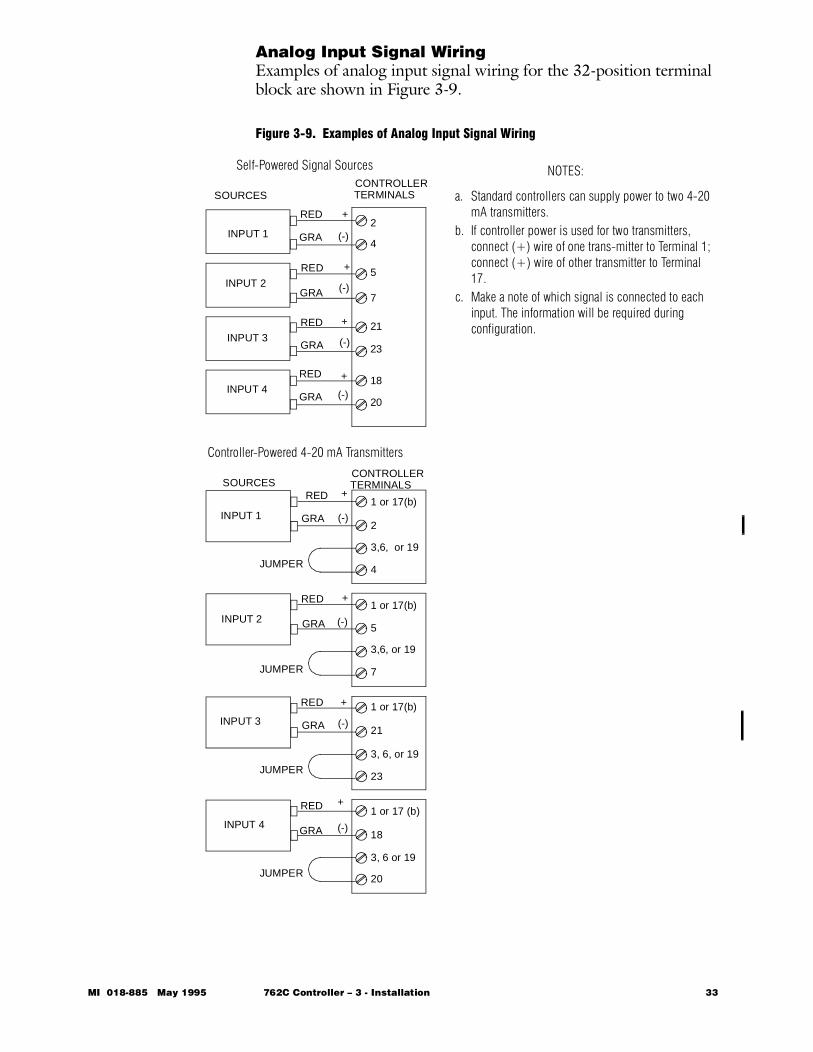
Analog Input Signal WiringExamples of analog input signal wiring for the 32-position terminal block are shown in Figure 3-9.
Figure 3-9. Examples of Analog Input Signal Wiring
Controller-Powered 4-20 mA Transmitters
Self-Powered Signal SourcesCONTROLLERTERMINALS SOURCES
SOURCESCONTROLLERTERMINALS
INPUT 1
INPUT 2
INPUT 3
INPUT 4
INPUT 1
INPUT 2
INPUT 3
INPUT 4
RED
GRA
RED
RED
RED
RED
RED
RED
RED
GRA
GRA
GRA
GRA
GRA
GRA
GRA
+
+
+
+
+
+
+
+
(-)
(-)
(-)
(-)
(-)
(-)
(-)
(-)
JUMPER
JUMPER
JUMPER
JUMPER
1 or 17(b)
2
3,6, or 19
4
1 or 17(b)
5
3,6, or 19
7
1 or 17(b)
21
3, 6, or 19
23
1 or 17 (b)
18
3, 6 or 19
20
2
4
5
7
21
23
18
20
NOTES:
a. Standard controllers can supply power to two 4-20 mA transmitters.
b. If controller power is used for two transmitters, connect (+) wire of one trans-mitter to Terminal 1; connect (+) wire of other transmitter to Terminal 17.
c. Make a note of which signal is connected to each input. The information will be required during configuration.
MI 018-885 May 1995 762C Controller – 3 - Installation 33
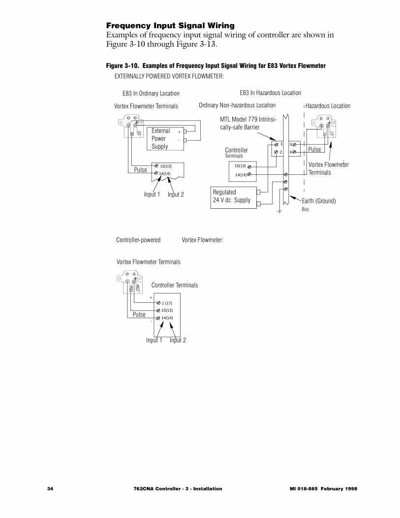
Frequency Input Signal WiringExamples of frequency input signal wiring of controller are shown in Figure 3-10 through Figure 3-13.
Figure 3-10. Examples of Frequency Input Signal Wiring for E83 Vortex Flowmeter
Controller Terminals
Vortex Flowmeter Terminals
EXTERNALLY POWERED VORTEX FLOWMETER:
Controller-powered Vortex Flowmeter:
E83 In Ordinary Location E83 In Hazardous Location
+
+ +
Pulse
Input 1
+
-
1 (17)
15(13)
14(14)
Input 2
A B
Vortex Flowmeter Terminals
External PowerSupply Controller
Terminals
Pulse14(14)
Input 1 Input 2
Ordinary Non-hazardous Location Hazardous Location
Vortex Flowmeter Terminals
MTL Model 779 Intrinsi-cally-safe Barrier
15(13)
14(14)
Regulated 24 V dc Supply Earth (Ground)
Bus
Pulse1
15(13)
2
3
4
+
-
--
34 762CNA Controller - 3 - Installation MI 018-885 February 1998
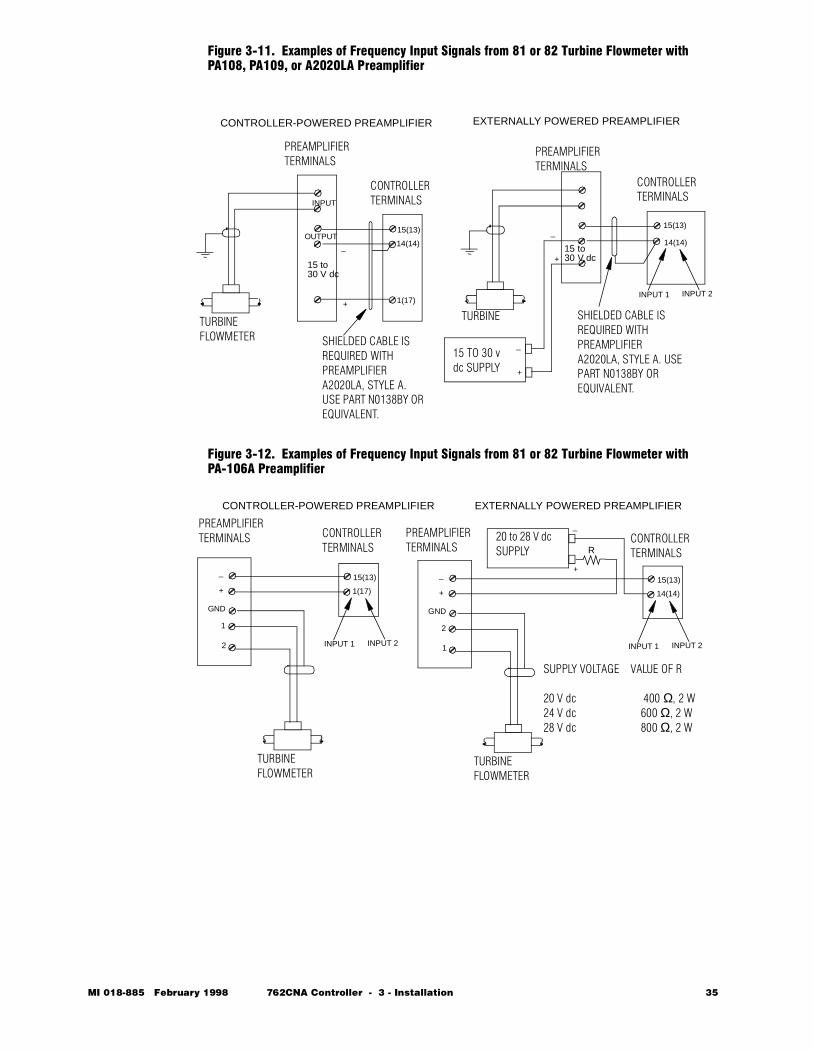
Figure 3-11. Examples of Frequency Input Signals from 81 or 82 Turbine Flowmeter with PA108, PA109, or A2020LA Preamplifier
Figure 3-12. Examples of Frequency Input Signals from 81 or 82 Turbine Flowmeter with PA-106A Preamplifier
15 TO 30 v dc SUPPLY
CONTROLLERTERMINALS
CONTROLLERTERMINALS
PREAMPLIFIERTERMINALS
TURBINE
15(13) 15(13)
14(14)
INPUT
OUTPUT
+
_ 14(14)
1(17)
TURBINE FLOWMETER
15 to30 V dc
SHIELDED CABLE IS REQUIRED WITH PREAMPLIFIER A2020LA, STYLE A. USE PART N0138BY OR EQUIVALENT.
SHIELDED CABLE IS REQUIRED WITH PREAMPLIFIER A2020LA, STYLE A. USE PART N0138BY OR EQUIVALENT.
PREAMPLIFIERTERMINALS
INPUT 1 INPUT 2
15 to30 V dc+
_
CONTROLLER-POWERED PREAMPLIFIER EXTERNALLY POWERED PREAMPLIFIER
+
_
20 to 28 V dc SUPPLY
EXTERNALLY POWERED PREAMPLIFIER
CONTROLLERTERMINALS
PREAMPLIFIERTERMINALS
15(13)
+
_
14(14)
TURBINE FLOWMETER
GND
2
1 INPUT 1 INPUT 2
R
+
_
SUPPLY VOLTAGE VALUE OF R
20 V dc 400 Ω, 2 W24 V dc 600 Ω, 2 W28 V dc 800 Ω, 2 W
CONTROLLERTERMINALS
PREAMPLIFIERTERMINALS
15(13)
+
_
1(17)
TURBINE FLOWMETER
CONTROLLER-POWERED PREAMPLIFIER
GND
1
2 INPUT 1 INPUT 2
MI 018-885 February 1998 762CNA Controller - 3 - Installation 35
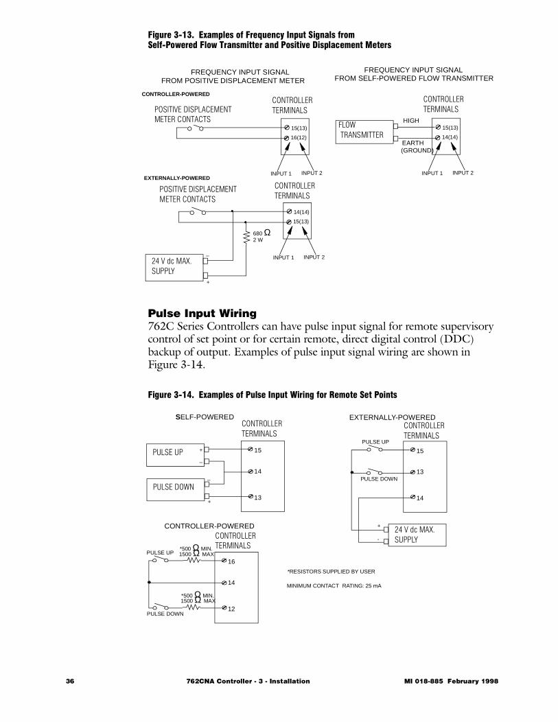
Figure 3-13. Examples of Frequency Input Signals from Self-Powered Flow Transmitter and Positive Displacement Meters
Pulse Input Wiring762C Series Controllers can have pulse input signal for remote supervisory control of set point or for certain remote, direct digital control (DDC) backup of output. Examples of pulse input signal wiring are shown in Figure 3-14.
Figure 3-14. Examples of Pulse Input Wiring for Remote Set Points
24 V dc MAX.SUPPLY
FREQUENCY INPUT SIGNAL
+
_
FROM SELF-POWERED FLOW TRANSMITTER
FLOW TRANSMITTER
CONTROLLERTERMINALS
15(13)
14(14)
INPUT 1 INPUT 2
HIGH
EARTH(GROUND)
CONTROLLERTERMINALS
15(13)
16(12)
INPUT 1 INPUT 2
CONTROLLER-POWERED
FREQUENCY INPUT SIGNALFROM POSITIVE DISPLACEMENT METER
POSITIVE DISPLACEMENT METER CONTACTS
CONTROLLERTERMINALS
14(14)
15(13)
INPUT 1 INPUT 2
EXTERNALLY-POWERED
POSITIVE DISPLACEMENT METER CONTACTS
680 Ω2 W
+
_
PULSE UP_
+
PULSE DOWN
+
_
CONTROLLERTERMINALS
15
14
13
CONTROLLERTERMINALS
16
14
12
PULSE UP
PULSE DOWN
*500 Ω MIN.1500 Ω MAX
CONTROLLERTERMINALS
15
13
14
PULSE UP
PULSE DOWN
SELF-POWERED
CONTROLLER-POWERED
EXTERNALLY-POWERED
MINIMUM CONTACT RATING: 25 mA
*RESISTORS SUPPLIED BY USER
24 V dc MAX.SUPPLY
+
-
*500 Ω MIN.1500 Ω MAX
36 762CNA Controller - 3 - Installation MI 018-885 February 1998
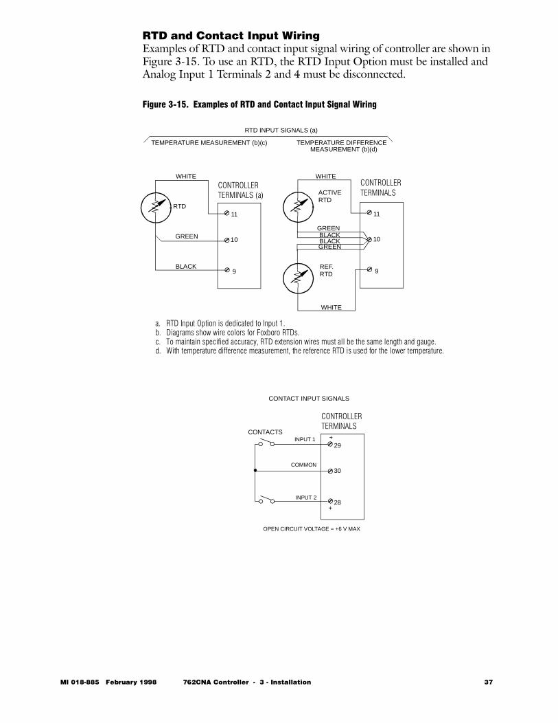
RTD and Contact Input WiringExamples of RTD and contact input signal wiring of controller are shown in Figure 3-15. To use an RTD, the RTD Input Option must be installed and Analog Input 1 Terminals 2 and 4 must be disconnected.
Figure 3-15. Examples of RTD and Contact Input Signal Wiring
CONTROLLERTERMINALS
29
30
28
OPEN CIRCUIT VOLTAGE = +6 V MAX
+
+CONTACTS
COMMON
INPUT 1
INPUT 2
CONTROLLERTERMINALS
11
10
9
CONTROLLERTERMINALS (a)
11
10
9
GREENBLACKBLACKGREEN
WHITE
WHITE
REF.RTD
ACTIVERTD
WHITE
GREEN
BLACK
RTD
TEMPERATURE MEASUREMENT (b)(c) TEMPERATURE DIFFERENCEMEASUREMENT (b)(d)
CONTACT INPUT SIGNALS
RTD INPUT SIGNALS (a)
a. RTD Input Option is dedicated to Input 1.b. Diagrams show wire colors for Foxboro RTDs.c. To maintain specified accuracy, RTD extension wires must all be the same length and gauge.d. With temperature difference measurement, the reference RTD is used for the lower temperature.
MI 018-885 February 1998 762CNA Controller - 3 - Installation 37
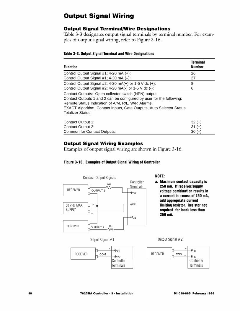
Output Signal Wiring
Output Signal Terminal/Wire Designations Table 3-3 designates output signal terminals by terminal number. For exam-ples of output signal wiring, refer to Figure 3-16.
Output Signal Wiring ExamplesExamples of output signal wiring are shown in Figure 3-16.
Figure 3-16. Examples of Output Signal Wiring of Controller
Table 3-3. Output Signal Terminal and Wire Designations
FunctionTerminal Number
Control Output Signal #1; 4-20 mA (+):Control Output Signal #1; 4-20 mA (–):
2627
Control Output Signal #2; 4-20 mA(+) or 1-5 V dc (+):Control Output Signal #2; 4-20 mA(-) or 1-5 V dc (-):
86
Contact Outputs: Open collector switch (NPN) output.Contact Outputs 1 and 2 can be configured by user for the following: Remote Status Indication of A/M, R/L, W/P, Alarms,EXACT Algorithm, Contact Inputs, Gate Outputs, Auto Selector Status, Totalizer Status.
Contact Output 1:Contact Output 2:Common for Contact Outputs:
32 (+)31 (+)30 (–)
ControllerTerminals
RECEIVER
+
RECEIVER
+
_26
27
32
30
31
COM
_
RECEIVER
+
_8
6COM
50 V dc MAX.SUPPLY
RECEIVER
OUTPUT 1
OUTPUT 2
_
Contact Output Signals
Output Signal #1 Output Signal #2
(a)
(a)
NOTE:a. Maximum contact capacity is
250 mA. If receiver/supply voltage combination results in a current in excess of 250 mA, add appropriate current limiting resistor. Resistor not required for loads less than 250 mA.
ControllerTerminals
ControllerTerminals
38 762CNA Controller - 3 - Installation MI 018-885 February 1998
Serial Communication WiringThis section describes installation of wiring for serial communication func-tions. Refer to “Serial Communications” on page 101 for important config-uration details. For detailed programming information, refer to MI 018-888, Serial Communication Guide for 762C and 743CB Controllers.
Terminal/Wire Designations Table 3-4 designates terminals for serial communications wiring by terminal number for a controller. For examples of serial communications wiring, refer to the next section. If controller has optional surge protection, see “Accessory Equipment” on page 41 for wiring details.
RS-485 is used for serial communication of measurement, set point, output, alarm, and status signals. Maximum num-ber of controllers that can be connected in a single loop is 30. Maximum accumulated cable length is 1.5 km (5000 ft).
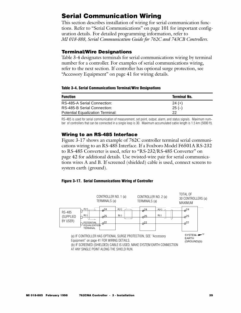
Wiring to an RS-485 InterfaceFigure 3-17 shows an example of 762C controller terminal serial communi-cations wiring to an RS-485 Interface. If a Foxboro Model F6501A RS-232 to RS-485 Converter is used, refer to “RS-232/RS-485 Converter” on page 42 for additional details. Use twisted-wire pair for serial communica-tions wires A and B. If screened (shielded) cable is used, connect screens to system earth (ground).
Figure 3-17. Serial Communications Wiring of Controller
Table 3-4. Serial Communications Terminal/Wire Designations
Function Terminal No.
RS-485-A Serial Connection:RS-485-B Serial Connection:Potential Equalization Terminal:
24 (+)25 (–)22
RS-485(SUPPLIED BY USER)
CONTROLLER NO. 1 (a)TERMINALS (a)
24
25
22POTENTIAL
CONTROLLER NO. 2 (a)TERMINALS (a)
24
25
22
TOTAL OF30 CONTROLLERS (a)MAXIMUM
24
25
22
A(+)
B(-)
A(+) A(+)
B(-) B(-)
SYSTEMEARTH(GROUND)(b)
(a) IF CONTROLLER HAS OPTIONAL SURGE PROTECTION, SEE “Accessory Equipment” on page 41 FOR WIRING DETAILS.(b) IF SCREENED (SHIELDED) CABLE IS USED, MAKE SYSTEM EARTH CONNECTION AT ANY SINGLE POINT ALONG THE SHIELD RUN.
EQUALIZATIONTERMINAL
MI 018-885 February 1998 762CNA Controller - 3 - Installation 39
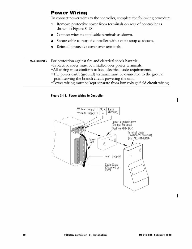
Power WiringTo connect power wires to the controller, complete the following procedure.
1 Remove protective cover from terminals on rear of controller as shown in Figure 3-18.
2 Connect wires to applicable terminals as shown.3 Secure cable to rear of controller with a cable strap as shown.4 Reinstall protective cover over terminals.
WARNING For protection against fire and electrical shock hazards:•Protective cover must be installed over power terminals.•All wiring must conform to local electrical code requirements.•The power earth (ground) terminal must be connected to the ground
point serving the branch circuit powering the unit.•Power wiring must be kept separate from low voltage field circuit wiring.
Figure 3-18. Power Wiring to Controller
Power Terminal Cover
PowerCord
With ac Supply
With dc SupplyL1+
N(L2)_
Earth(Ground)
Rear Support
Cable Strap(Supplied byuser)
(General Purpose)
Terminal Cover(Division 2 Locations)
(Part No.K0143AH)
(Part No.K0143DU)
40 762CNA Controller - 3 - Installation MI 018-885 February 1998
Accessory EquipmentThis section describes the installation of common accessory devices, such as a surge suppressor, an RS-232/RS-485 converter, and an Opto-22 con-verter.
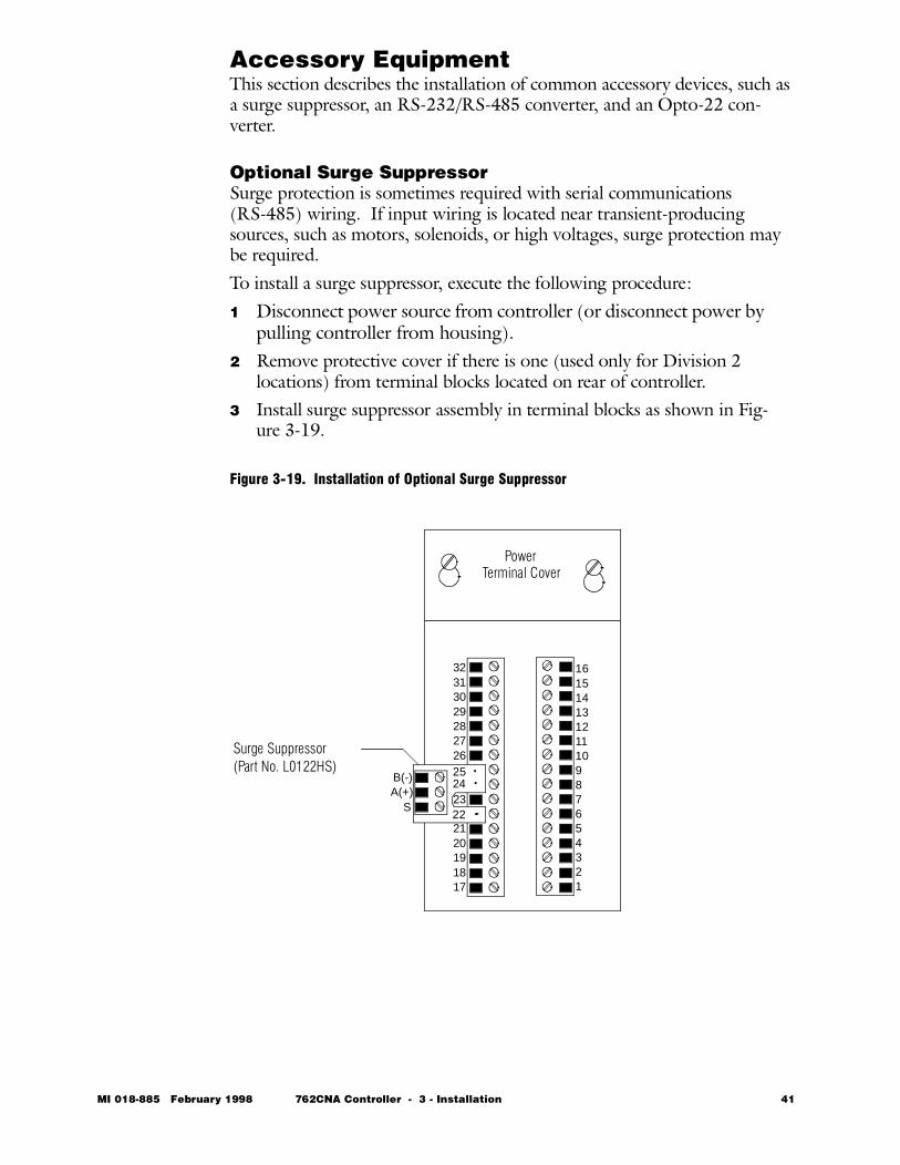
Optional Surge SuppressorSurge protection is sometimes required with serial communications (RS-485) wiring. If input wiring is located near transient-producing sources, such as motors, solenoids, or high voltages, surge protection may be required. To install a surge suppressor, execute the following procedure:1 Disconnect power source from controller (or disconnect power by
pulling controller from housing).2 Remove protective cover if there is one (used only for Division 2
locations) from terminal blocks located on rear of controller. 3 Install surge suppressor assembly in terminal blocks as shown in Fig-
ure 3-19.
Figure 3-19. Installation of Optional Surge Suppressor
16151413121110987654321
32313029282726252423222120191817
25 24
22
Terminal Cover
Surge Suppressor
B(-)A(+)
S
Power
(Part No. L0122HS)
MI 018-885 February 1998 762CNA Controller - 3 - Installation 41
Optional Surge Suppressor (cont.)
4 Connect wires referenced in Figure 3-17 to the corresponding termi-nals on the suppressor assembly. For input wiring to the surge sup-pressor, use twisted-wire pair.
Input Wiring to Surge Suppressor
1 Connect wires from RS-485 to terminals of surge suppressor as shown in Figure 3-19. Use twisted-wire pair.
2 If screened (shielded) cable is used, connect screen to system earth (ground).
RS-232/RS-485 ConverterThe Foxboro RS-232 to RS-485 Converter provides the interface between the RS-485 field-wiring (twisted-wire pairs) and the RS-232 communica-tions for the host computer, as shown in Table 3-5.
Table 3-5. RS-232/RS-485 Converter Specifications
Item Specification
Supply Voltage Limits
120, 220, or 240 V ac +10% and -15%. Supply voltage as specified in sales order.
Supply Frequency Limits
50 or 60 Hz; ±3 Hz.
Inputs Accepts up to three independent RS-485 twisted-wire pairs. Each pair can have up to thirty controllers connected to it.The other input is the RS-232 connection to the host computer.
Connections Terminal block for RS-485 twisted-wire pair terminations and 25-pin D-type connector for RS-232 cable.
42 762CNA Controller - 3 - Installation MI 018-885 February 1998
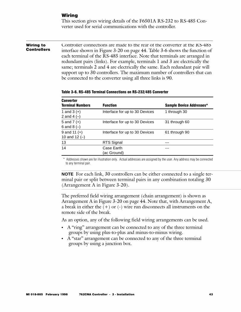
WiringThis section gives wiring details of the F6501A RS-232 to RS-485 Con-verter used for serial communications with the controller.
Wiring to Controllers
Controller connections are made to the rear of the converter at the RS-485 interface shown in Figure 3-20 on page 44. Table 3-6 shows the function of each terminal of the RS-485 interface. Note that terminals are arranged in redundant pairs (links). For example, terminals 1 and 3 are electrically the same; terminals 2 and 4 are electrically the same. Each redundant pair will support up to 30 controllers. The maximum number of controllers that can be connected to the converter using all three links is 90.
* Addresses shown are for illustration only. Actual addresses are assigned by the user. Any address may be connectedto any terminal pair.
NOTE For each link, 30 controllers can be either connected to a single ter-minal pair or split between terminal pairs in any combination totaling 30 (Arrangement A in Figure 3-20).
The preferred field wiring arrangement (chain arrangement) is shown as Arrangement A in Figure 3-20 on page 44. Note that, with Arrangement A, a break in either the (+) or (-) wire run disconnects all instruments on the remote side of the break.As an option, any of the following field wiring arrangements can be used. • A “ring” arrangement can be connected to any of the three terminal
groups by using plus-to-plus and minus-to-minus wiring.• A “star” arrangement can be connected to any of the three terminal
groups by using a junction box.
Table 3-6. RS-485 Terminal Connections on RS-232/485 Converter
ConverterTerminal Numbers Function Sample Device Addresses*
1 and 3 (+)2 and 4 (–)
Interface for up to 30 Devices 1 through 30
5 and 7 (+)6 and 8 (–)
Interface for up to 30 Devices 31 through 60
9 and 11 (+)10 and 12 (–)
Interface for up to 30 Devices 61 through 90
13 RTS Signal ---14 Case Earth
(ac Ground)---
MI 018-885 February 1998 762CNA Controller - 3 - Installation 43
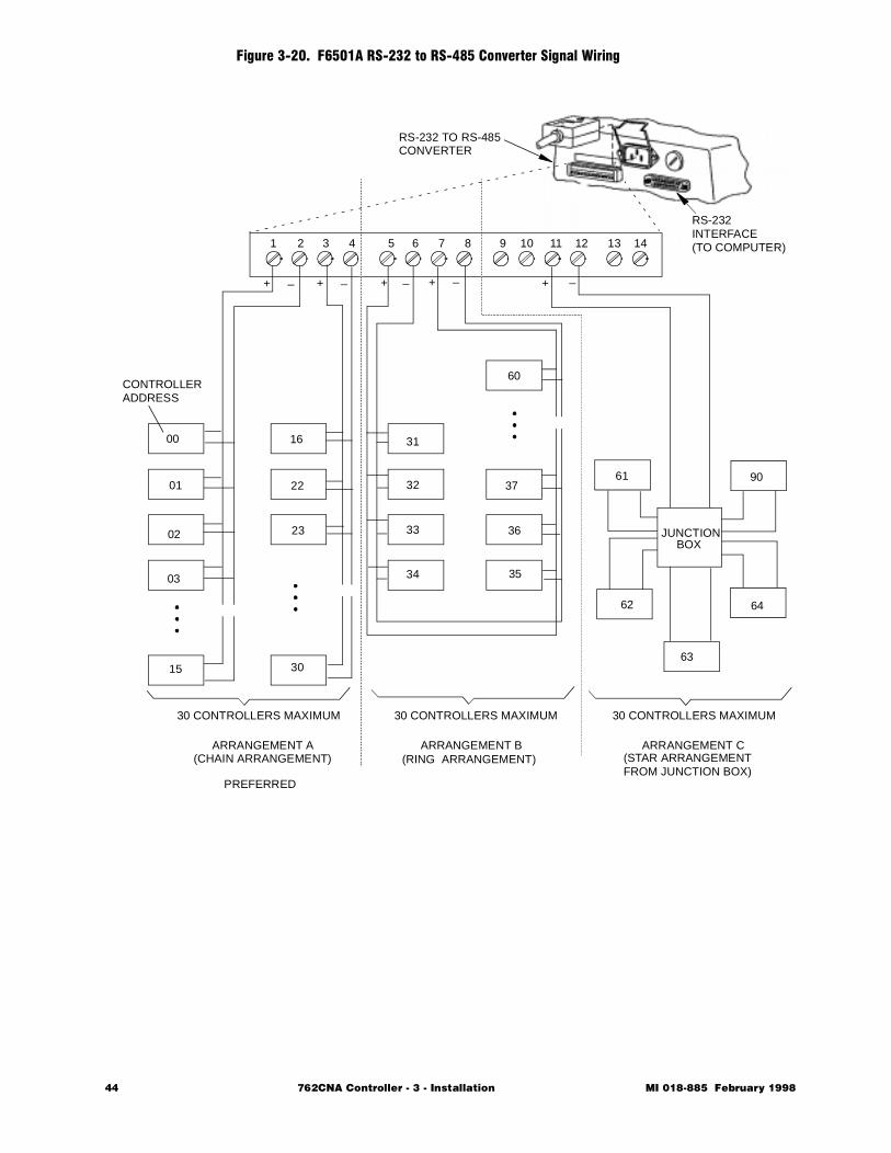
Figure 3-20. F6501A RS-232 to RS-485 Converter Signal Wiring
JUNCTIONBOX
1 2 3 4 5 6 7 8 9 10 11 12 13 14
+ _ + + + +_ _ _ _
00
01
02
03
15
16
22
23
30
31
32
33
34
60
37
36
35
61
62
63
90
64
30 CONTROLLERS MAXIMUM 30 CONTROLLERS MAXIMUM 30 CONTROLLERS MAXIMUM
ARRANGEMENT A(CHAIN ARRANGEMENT)
ARRANGEMENT B ARRANGEMENT C(RING ARRANGEMENT) (STAR ARRANGEMENT
FROM JUNCTION BOX)
CONTROLLERADDRESS
RS-232 TO RS-485CONVERTER
RS-232INTERFACE(TO COMPUTER)
PREFERRED
44 762CNA Controller - 3 - Installation MI 018-885 February 1998
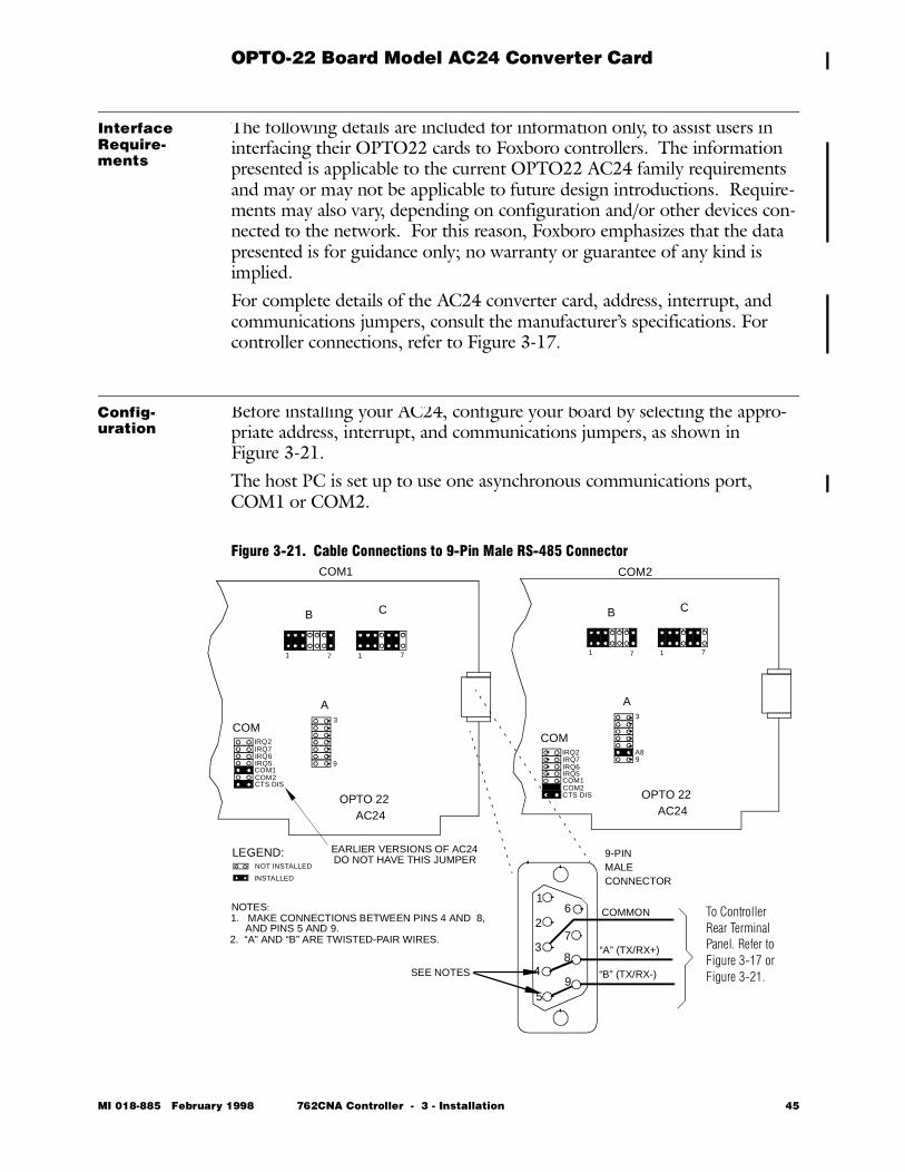
OPTO-22 Board Model AC24 Converter Card
Interface Require-ments
The following details are included for information only, to assist users in interfacing their OPTO22 cards to Foxboro controllers. The information presented is applicable to the current OPTO22 AC24 family requirements and may or may not be applicable to future design introductions. Require-ments may also vary, depending on configuration and/or other devices con-nected to the network. For this reason, Foxboro emphasizes that the data presented is for guidance only; no warranty or guarantee of any kind is implied.For complete details of the AC24 converter card, address, interrupt, and communications jumpers, consult the manufacturer’s specifications. For controller connections, refer to Figure 3-17.
Config-uration
Before installing your AC24, configure your board by selecting the appro-priate address, interrupt, and communications jumpers, as shown inFigure 3-21.The host PC is set up to use one asynchronous communications port, COM1 or COM2.
Figure 3-21. Cable Connections to 9-Pin Male RS-485 Connector
9-PINMALECONNECTOR
COMMON
“A” (TX/RX+)
“B” (TX/RX-)
1
2
3
4
5
6
7
8
9
B C
A
COM1
OPTO 22AC24
1 7 1 7
3
9
LEGEND:NOT INSTALLED
INSTALLED
B C
A
COM
COM2
OPTO 22AC24
1 7 1 7
3
9
EARLIER VERSIONS OF AC24DO NOT HAVE THIS JUMPER
SEE NOTES
NOTES:1. MAKE CONNECTIONS BETWEEN PINS 4 AND 8,
2. “A” AND “B” ARE TWISTED-PAIR WIRES. AND PINS 5 AND 9.
A8IRQ2IRQ7IRQ6IRQ5COM1COM2CTS DIS
COMIRQ2IRQ7IRQ6IRQ5COM1COM2CTS DIS
To Controller Rear Terminal Panel. Refer to Figure 3-17 or Figure 3-21.
MI 018-885 February 1998 762CNA Controller - 3 - Installation 45

46 762CNA Controller - 3 - Installation MI 018-885 February 1998

762C SINGLESTATION
MICROController
February 1998
Preface • xiii Chapter 1 Quick Check • 1 Chapter 2 Product Overview • 11 Chapter 3 Installation • 23
Ð Chapter 4 Configuration • 49 Chapter 5 Operation • 109 Chapter 6 EXACT Tuning • 135 Chapter 7 Calibration, Troubleshooting,
Maintenance • 159 Appendix A Specifications • 183 Appendix B Configuration Worksheets • 193 Appendix C Structure Diagrams • 237 Appendix D Parts List • 247 Appendix E Dimensional Print • 255 Appendix F Functional Diagram • 261 Glossary • 267 Index • 287
The Intelligent Automation People

48 762CNA Controller MI 018-885 February 1998
MI 018-885 Februar
4 Configuration
This chapter describes all configuration options and defines procedures for implementing them. If you have not yet read Chapter 2 - Product Overview, we suggest that you do so before proceeding.The chapter is divided into the following major sections:• Introduction • 50 • Common Configuration Functions • 58 • Alarms • 64 • Alternate Station Configurations • 76 • Additional Configuration Functions • 80 • Configuration Copy Accessory • 105
y 1998 762CNA Controller - 4 - Configuration 49
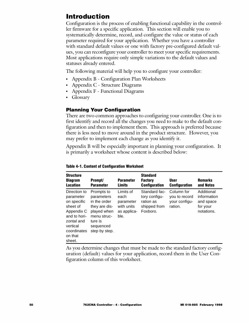
IntroductionConfiguration is the process of enabling functional capability in the control-ler firmware for a specific application. This section will enable you to systematically determine, record, and configure the value or status of each parameter required for your application. Whether you have a controller with standard default values or one with factory pre-configured default val-ues, you can reconfigure your controller to meet your specific requirements. Most applications require only simple variations to the default values and statuses already entered. The following material will help you to configure your controller:• Appendix B - Configuration Plan Worksheets• Appendix C - Structure Diagrams • Appendix F - Functional Diagrams• Glossary
Planning Your ConfigurationThere are two common approaches to configuring your controller. One is to first identify and record all the changes you need to make to the default con-figuration and then to implement them. This approach is preferred because there is less need to move around in the product structure. However, you may prefer to implement each change as you identify it.Appendix B will be especially important in planning your configuration. It is primarily a worksheet whose content is described below:
As you determine changes that must be made to the standard factory config-uration (default) values for your application, record them in the User Con-figuration column of this worksheet.
Table 4-1. Content of Configuration Worksheet
StructureDiagramLocation
Prompt/Parameter
ParameterLimits
StandardFactoryConfiguration
User Configuration
Remarksand Notes
Direction to parameter on specific sheet of Appendix C and to hori-zontal and vertical coordinates on that sheet.
Prompts to parameters in the order they are dis-played when menu struc-ture is sequenced step by step.
Limits of each parameter with units as applica-ble.
Standard fac-tory configu-ration as shipped from Foxboro.
Column for you to record your configu-ration.
Additional information and space for your notations.
50 762CNA Controller - 4 - Configuration MI 018-885 February 1998
Planning Your Configuration (cont.)Throughout the Configuration section of this instruction, you will find location designators (e.g., 2 - A3). These direct you to the parameter you are looking for in the structure diagram in Appendix C. In the example given, the 2 refers to the diagram beginning with Balloon 2 in the upper left corner. The designation A3 refers to map coordinates on that diagram.
NOTE Diagrams in Locations 2, 3, 6, and 7 are so simple that map coor-dinates are not used.
More detailed information on using the structure diagrams is located in the beginning of Appendix C.During configuration, you will need to access various signals such as inputs, outputs, measurements, set points, and calculated values. These are located in a Signal Distribution List which is in Location 6 in the structure and explained in Table 4-2 on page 52.You will also need to access alarms, gates, contact inputs, and other logic functions to initiate actions. These are located in the Gate Input List in Location 7 in the structure and explained in Table 4-3 on page 53.Appendix F provides a functional overview of the controller. It can be used with Appendix B, Configuration Worksheets, and Appendix C, Structure Diagrams, to select the product capability needed to match your applica-tion.
MI 018-885 February 1998 762CNA Controller - 4 - Configuration 51
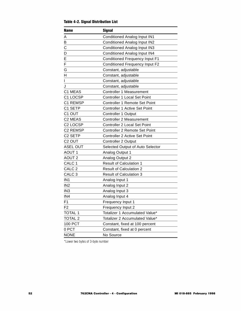
*Lower two bytes of 3-byte number
Table 4-2. Signal Distribution List
Name Signal
A Conditioned Analog Input IN1B Conditioned Analog Input IN2C Conditioned Analog Input IN3D Conditioned Analog Input IN4E Conditioned Frequency Input F1F Conditioned Frequency Input F2G Constant, adjustableH Constant, adjustableI Constant, adjustableJ Constant, adjustableC1 MEAS Controller 1 MeasurementC1 LOCSP Controller 1 Local Set PointC1 REMSP Controller 1 Remote Set PointC1 SETP Controller 1 Active Set PointC1 OUT Controller 1 OutputC2 MEAS Controller 2 MeasurementC2 LOCSP Controller 2 Local Set PointC2 REMSP Controller 2 Remote Set PointC2 SETP Controller 2 Active Set PointC2 OUT Controller 2 OutputASEL OUT Selected Output of Auto SelectorAOUT 1 Analog Output 1AOUT 2 Analog Output 2CALC 1 Result of Calculation 1CALC 2 Result of Calculation 2CALC 3 Result of Calculation 3IN1 Analog Input 1IN2 Analog Input 2IN3 Analog Input 3IN4 Analog Input 4F1 Frequency Input 1F2 Frequency Input 2TOTAL 1 Totalizer 1 Accumulated Value*TOTAL 2 Totalizer 2 Accumulated Value*100 PCT Constant, fixed at 100 percent0 PCT Constant, fixed at 0 percentNONE No Source
52 762CNA Controller - 4 - Configuration MI 018-885 February 1998
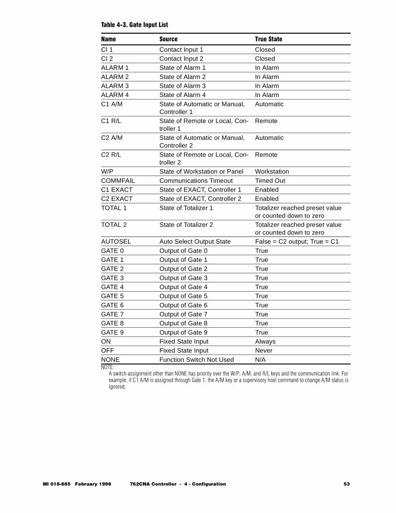
NOTE: A switch assignment other than NONE has priority over the W/P, A/M, and R/L keys and the communication link. For example, if C1 A/M is assigned through Gate 1, the A/M key or a supervisory host command to change A/M status is ignored.
Table 4-3. Gate Input List
Name Source True State
CI 1 Contact Input 1 ClosedCI 2 Contact Input 2 ClosedALARM 1 State of Alarm 1 In AlarmALARM 2 State of Alarm 2 In AlarmALARM 3 State of Alarm 3 In AlarmALARM 4 State of Alarm 4 In AlarmC1 A/M State of Automatic or Manual,
Controller 1Automatic
C1 R/L State of Remote or Local, Con-troller 1
Remote
C2 A/M State of Automatic or Manual, Controller 2
Automatic
C2 R/L State of Remote or Local, Con-troller 2
Remote
W/P State of Workstation or Panel WorkstationCOMMFAIL Communications Timeout Timed OutC1 EXACT State of EXACT, Controller 1 EnabledC2 EXACT State of EXACT, Controller 2 EnabledTOTAL 1 State of Totalizer 1 Totalizer reached preset value
or counted down to zeroTOTAL 2 State of Totalizer 2 Totalizer reached preset value
or counted down to zeroAUTOSEL Auto Select Output State False = C2 output; True = C1GATE 0 Output of Gate 0 TrueGATE 1 Output of Gate 1 TrueGATE 2 Output of Gate 2 TrueGATE 3 Output of Gate 3 TrueGATE 4 Output of Gate 4 TrueGATE 5 Output of Gate 5 TrueGATE 6 Output of Gate 6 TrueGATE 7 Output of Gate 7 TrueGATE 8 Output of Gate 8 TrueGATE 9 Output of Gate 9 TrueON Fixed State Input AlwaysOFF Fixed State Input NeverNONE Function Switch Not Used N/A
MI 018-885 February 1998 762CNA Controller - 4 - Configuration 53
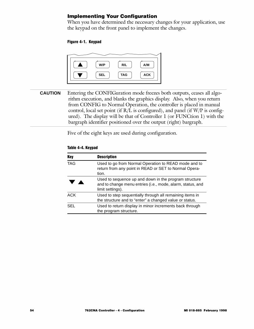
Implementing Your ConfigurationWhen you have determined the necessary changes for your application, use the keypad on the front panel to implement the changes.
Figure 4-1. Keypad
CAUTION Entering the CONFIGuration mode freezes both outputs, ceases all algo-rithm execution, and blanks the graphics display. Also, when you return from CONFIG to Normal Operation, the controller is placed in manual control, local set point (if R/L is configured), and panel (if W/P is config-ured). The display will be that of Controller 1 (or FUNCtion 1) with the bargraph identifier positioned over the output (right) bargraph.
Five of the eight keys are used during configuration.
W/P R/L A/M
SEL TAG ACK
Table 4-4. Keypad
Key Description
TAG Used to go from Normal Operation to READ mode and to return from any point in READ or SET to Normal Opera-tion.Used to sequence up and down in the program structure and to change menu entries (i.e., mode, alarm, status, and limit settings).
ACK Used to step sequentially through all remaining items in the structure and to “enter” a changed value or status.
SEL Used to return display in minor increments back through the program structure.
54 762CNA Controller - 4 - Configuration MI 018-885 February 1998
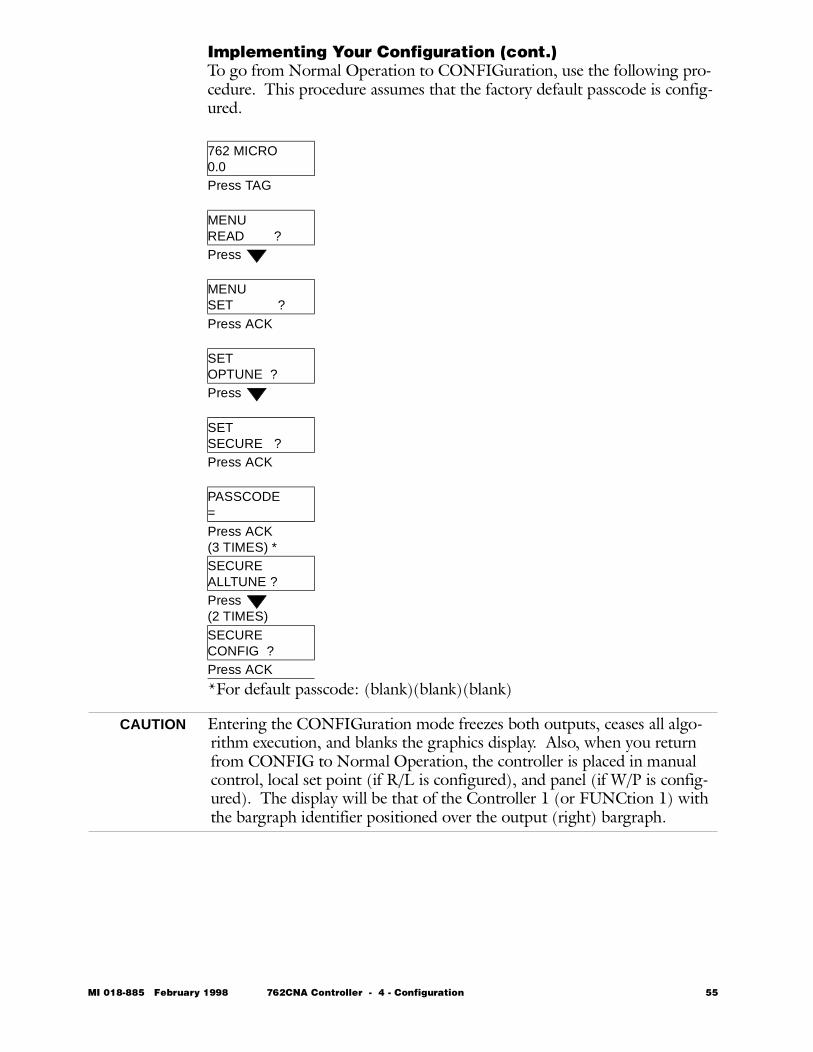
Implementing Your Configuration (cont.)To go from Normal Operation to CONFIGuration, use the following pro-cedure. This procedure assumes that the factory default passcode is config-ured.
*For default passcode: (blank)(blank)(blank)
CAUTION Entering the CONFIGuration mode freezes both outputs, ceases all algo-rithm execution, and blanks the graphics display. Also, when you return from CONFIG to Normal Operation, the controller is placed in manual control, local set point (if R/L is configured), and panel (if W/P is config-ured). The display will be that of the Controller 1 (or FUNCtion 1) with the bargraph identifier positioned over the output (right) bargraph.
762 MICRO0.0Press TAG
MENUREAD ?Press
MENU SET ?Press ACK
SETOPTUNE ?Press
SETSECURE ?Press ACK
PASSCODE=Press ACK(3 TIMES) *SECUREALLTUNE ?Press(2 TIMES)SECURECONFIG ?Press ACK
MI 018-885 February 1998 762CNA Controller - 4 - Configuration 55
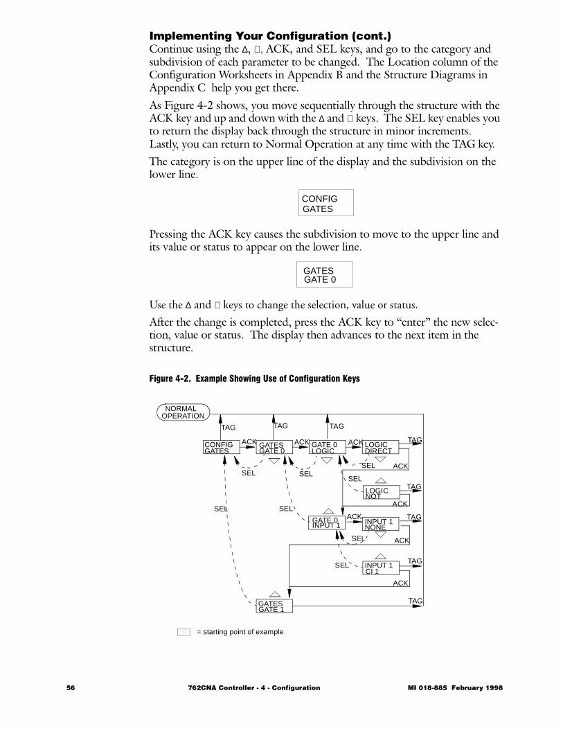
Implementing Your Configuration (cont.)Continue using the ∆, ∇, ACK, and SEL keys, and go to the category and subdivision of each parameter to be changed. The Location column of the Configuration Worksheets in Appendix B and the Structure Diagrams in Appendix C help you get there.As Figure 4-2 shows, you move sequentially through the structure with the ACK key and up and down with the ∆ and ∇ keys. The SEL key enables you to return the display back through the structure in minor increments. Lastly, you can return to Normal Operation at any time with the TAG key.The category is on the upper line of the display and the subdivision on the lower line.
Pressing the ACK key causes the subdivision to move to the upper line and its value or status to appear on the lower line.
Use the ∆ and ∇ keys to change the selection, value or status.
After the change is completed, press the ACK key to “enter” the new selec-tion, value or status. The display then advances to the next item in the structure.
Figure 4-2. Example Showing Use of Configuration Keys
CONFIGGATES
GATESGATE 0
NORMALOPERATION
CONFIGGATES
GATESGATE 0
GATESGATE 1
GATE 0LOGIC
GATE 0INPUT 1
LOGICDIRECT
LOGICNOT
INPUT 1NONE
INPUT 1CI 1
ACK ACK ACK
ACK
ACK
ACK
TAG
TAG
TAG
TAG
TAG
TAGTAGTAG
SEL
SEL
SELSEL
SELSEL
SEL
SEL
ACK
ACK
= starting point of example
56 762CNA Controller - 4 - Configuration MI 018-885 February 1998
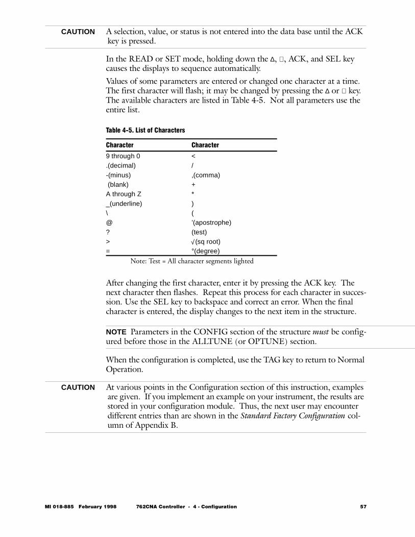
CAUTION A selection, value, or status is not entered into the data base until the ACK key is pressed.
In the READ or SET mode, holding down the ∆, ∇, ACK, and SEL key causes the displays to sequence automatically.Values of some parameters are entered or changed one character at a time. The first character will flash; it may be changed by pressing the ∆ or ∇ key. The available characters are listed in Table 4-5. Not all parameters use the entire list.
Note: Test = All character segments lighted
After changing the first character, enter it by pressing the ACK key. The next character then flashes. Repeat this process for each character in succes-sion. Use the SEL key to backspace and correct an error. When the final character is entered, the display changes to the next item in the structure.
NOTE Parameters in the CONFIG section of the structure must be config-ured before those in the ALLTUNE (or OPTUNE) section.
When the configuration is completed, use the TAG key to return to Normal Operation.
CAUTION At various points in the Configuration section of this instruction, examples are given. If you implement an example on your instrument, the results are stored in your configuration module. Thus, the next user may encounter different entries than are shown in the Standard Factory Configuration col-umn of Appendix B.
Table 4-5. List of Characters
Character Character
9 through 0 <.(decimal) /-(minus) ,(comma) (blank) +A through Z *_(underline) )\ (@ ’(apostrophe)? (test)> √ (sq root)= °(degree)
MI 018-885 February 1998 762CNA Controller - 4 - Configuration 57
Common Configuration FunctionsThis section contains the following subjects:• Security • 58 • Control Type and Tuning • 58 • Input Signals • 59 • Input Signal Conditioning and Scaling • 60 • Output Signals • 62 • Display Features • 62 • Auto/Manual Control (A/M) • 63
SecurityA PASSCODE enables you to prevent unauthorized personnel from chang-ing the configuration and those categories of values you choose to protect.The 762CNA Controller is shipped from the factory with a PASSCODE of three blanks. The passcode may be changed to three other characters. Any characters from Table 4-5 can be used. The configuration parameter to do this is NEWPASS. It is found in Location 5-C2 in the structure diagrams.After you enter the characters and press the ACK key, you are asked to enter them a second time as a verification (VERIFY). If the two entries match, the new passcode replaces the previous passcode.Under the configuration parameter SHOWOP (Location 2 in the structure diagrams), you can allow or prevent unauthorized personnel from changing the values of those parameters (TUNE C1, C1 LIMITS, TUNE C2, C2 LIMITS, ALARMS, CONSTS, TOTALS, RD CFG) that may be adjusted without the use of a PASSCODE (in OPTUNE). ACKnowledge YES for each parameter group that authorized personnel may adjust in OPTUNE. Note that SHOWOP categories displayed depend on whether the function is configured. For example, if neither totalizer is enabled, TOTALS does not appear under SHOWOP.
Control Type and TuningFor each controller, the standard algorithms are PI/PID, I, P/PD, and EXACT control. The factory default is PI/PID. If you select a different algorithm, you will need to configure a change. You can configure each of the two control FUNCtions at Location 5-A1 in the structure diagrams.Next determine your values for the algorithm selected. The parameter lim-its and the default configuration for Proportional (PF), integral (IF), and derivative (DF) control are as follows:Table 4-6. Control Parameter Limits
Parameter Limits Default
PF 1 and 8000% 200IF 0.01 and 200 minutes/repeat 2.0DF 0 and 100 minutes 0.0
58 762CNA Controller - 4 - Configuration MI 018-885 February 1998
Control Type and Tuning (cont.)Note that the PI and PID algorithms are grouped together as are the P and PD algorithms. To get PI or P, set DF to zero. To get PID or PD, set DF to a value.Set Point Lag (SP LAG), the ratio of lead to lag, can be configured between 0 and 1. Zero (0) means that no proportional gain is applied to the set point; all proportional gain is applied to the measurement. One (1) is used for a dominant deadtime process (delay). Typically, 0.2 is used for a domi-nant lag process. Details of EXACT parameters are discussed in Chapter 6 of this instruction manual. BYPASS causes the set point to go directly to output. Make a ON entry to enable bypass for Controller 1 at TUNE C1 and for Controller 2 at TUNE C2. The factory default is OFF. Both are at Location 4-A1 in the structure diagrams.
Input Signals
Analog Inputs
The 762CNA has four analog inputs (IN1, IN2, IN3, IN4). These inputs are 4-20 mA dc (through 250-ohm resistors). They can be changed to 1-5 V dc by removing the 250-ohm input termination resistors. One can be an RTD input. If you use an RTD input, you must configure it as IN1 and also have the RTD hardware option. IN1 through IN4 can be specified from the Signal Distribution List (Location 6 in the structure diagrams).
Frequency Inputs
The frequency/pulse inputs can be two 1 to 9999 Hz inputs or a pair of Pulse Up/Pulse Down inputs. Frequency rates below 1 Hz are cut off and ignored, producing the same results as inputs of 0 Hz. When configured as pulse inputs, F1 is the pulse up input and F2 is the pulse down input. The instantaneous difference between the pulse up and pulse down input is F2; the integrated difference is F1. F1 and F2 can be specified from the Signal Distribution List.In a pulse set point application (which emulates Foxboro 62HM control-lers), the following configuration entries must be made:
1 Select PULSED at FREQ I/P (Location 5-B2 in the structure dia-grams).
2 Configure the SET PT TYPE as R/L (Location 5-G1).3 Configure LOCTRK as ON (Location 5-H1).4 Configure SOURCE as CALC n (Location 5-H1).5 Configure CALC n as L+F (Location 5-C1). Signal F is the scaled
and conditioned version of F2.
MI 018-885 February 1998 762CNA Controller - 4 - Configuration 59
Input Signals (cont.)All analog or frequency input signals can be conditioned and scaled, charac-terized, or combined in a variety of calculations. These operations are dis-cussed later in this chapter.
Discrete Inputs
The controller also has two discrete (non-isolated contact or transistor switch) inputs, CI1 and CI2. You can use them, for example, to actuate remote status changes of auto/manual (A/M), remote/local (R/L), worksta-tion/panel (W/P), EXTernal ACKnowledge, tracking functions (MEAS-TRK and OUTTRK), and totalizer functions (HOLD and RESET). CI1 and CI2 are specified from the Gate Input List.
Input Signal Conditioning and ScalingEach of the analog and frequency inputs discussed above can be passed through a Butterworth FILTER adjusted for 0 to 10 minutes, then FOR-MATted as LINEAR, SQUARED, SQuare ROOTed, or CHARacterized over one of two selectable series of points. Lastly, an INBIAS may be applied before a GAIN and an OUTBIAS after the GAIN. The equation is:
See Figure 4-3 for a diagram representing the signal conditioning and scal-ing process.The order of these functions is reversed during configuration (i.e., OUT-BIAS, GAIN, INBIAS, FORMAT, and FILTER) at Location 5-B2 of the structure diagrams.Analog inputs IN1, IN2, IN3, and IN4 become signals A, B, C, and D after signal conditioning and scaling. Likewise, frequency inputs F1 and F2 become E and F.Four constants may be used, identified as G, H, I, and J. These may be adjusted through OPTUNE (if allowed) and ALLTUNE at Location 4-B2 of the structure diagrams.All conditioned inputs (A - F) and the constants (G - J) are available in the Signal Distribution List (Location 6).
FORMATted Input INBIAS+ ] GAIN×[ ) OUTBIAS+ Conditioned Input=
60 762CNA Controller - 4 - Configuration MI 018-885 February 1998
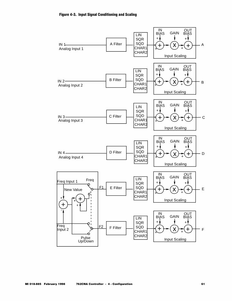
Figure 4-3. Input Signal Conditioning and Scaling
LINSQRSQD
CHAR1CHAR2
GAININ
BIASOUTBIAS
+
+
+
+
Input Scaling
LINSQRSQD
CHAR1CHAR2
GAININ
BIASOUTBIAS
+
+
+
+
Input Scaling
LINSQRSQD
CHAR1CHAR2
GAININ
BIASOUTBIAS
+
+
+
+
Input Scaling
LINSQRSQD
CHAR1CHAR2
GAININ
BIASOUTBIAS
+
+
+
+
Input Scaling
LINSQRSQD
CHAR1CHAR2
GAININ
BIASOUTBIAS
+
+
+
+
Input Scaling
LINSQRSQD
CHAR1CHAR2
GAININ
BIASOUTBIAS
+
+
+
+
Input Scaling
A
B
C
D
E
F
A Filter
B Filter
C Filter
D Filter
E Filter
F Filter
+
-
++
PulseUp/Down
F1
F2
Freq
New Value
IN 4
IN 1
IN 2
IN 3
Analog Input 1
Analog Input 2
Analog Input 3
Analog Input 4
Freq Input 1
FreqInput 2
+ +x
+ +x
+ +x
+ +x
+ +x
+ +x
++
MI 018-885 February 1998 762CNA Controller - 4 - Configuration 61
Output SignalsThe 762CNA has two analog output signals. AOUT1 is a 4 to 20 mA sig-nal into 500 ohms maximum. AOUT2 can be a 4 to 20 mA or 1 to 5 V dc, jumper selectable signal. You can configure either at Location 5-C2 in the structure diagrams to output a signal from the Signal Distribution List. Note, however, that certain configurations automatically assign the source of AOUT 1 and AOUT 2.The controller also has two discrete (non-isolated open collector transistor switch) outputs, CO1 and CO2. You can use them for status indication of A/M, R/L, W/P, and alarms. You can also configure them as the destination for any two of the Boolean gate outputs. Configuration is done at Location 5-C2 in the structure diagrams to output a signal from the Gate Input List.
Display Features
TAG The top line of the alphanumeric display can read a looptag of your choos-ing during normal operation mode. You can configure the TAGs for both the first and second controller to be up to a nine character ASCII text string. Enter the configuration at TAG in Location 5-E1 of the structure diagrams. Enter the TAG one character at a time as explained in “Implementing Your Configuration” on page 54.
Display Variable (in place of Looptag)
If an engineering variable is desired in place of a looptag, it may be config-ured at TOP LINE VARIABLE at Location 5-E1 in the structure diagrams. Enter its TYPE (LINEAR or TEMP), ENG UNiTS, range (URV and LRV), and SOURCE (from the Signal Distribution List). Thus, this func-tion provides a simple indication of any assigned SOURCE variable.
Measure- ment, Set Point Display (MEAS, SP)
In normal operation mode, the engineering scaled value of the measurement or set point, as identified by the Bargraph Identifier, is located on the sec-ond line of the alphanumeric display. Configure this display at MEAS, SP in Location 5-E2 by specifying its TYPE (LINEAR or TEMPerature), ENG UNiTS, and range (URV or LRV). If you select TEMPerature, spec-ify the SCALE as IEC 100 or SAMA 100 for an RTD input or T/C J, T/C K, or T/C E for a thermocouple input from a temperature transmitter. Also, specify the ENG UNiTS as DEG F or DEG C.
62 762CNA Controller - 4 - Configuration MI 018-885 February 1998
Auto/Manual Control (A/M)The controller can be placed in either an automatic (A) or manual (M) mode. This can be changed by the A/M key on the front of the controller if the controller is in panel mode (P) and if the function switch (A/M) is con-figured to NONE. A switch assignment other than NONE has priority over the A/M key. Auto or Manual control may be specified at Location 5-G2 under the following conditions:
STARTUP: A/M state upon application of power or restart after a power failure.FLUNK: A/M state upon loss of serial communications (when in Workstation
mode) between controller and host computer. Besides a choice of Auto or Manual, the configurator may also select the last status (LAST A/M) of control before serial communications was lost.
SWITCH: An entry from the Gate Input List here drives the specified SWITCH to change the controller operation from Auto to Manual or vice versa. A configuration of ON or to an entry from the Gate Input List whose logic is in the True state sets the control to the AUTO mode. Conversely, OFF or (False) sets the control to the MANUAL mode.
A switch assignment other than NONE has priority over the A/M key or the communication link; e.g., if A/M were assigned through Gate 1, then the A/M key or a supervisory host command to change A/M status would be ignored.
MI 018-885 February 1998 762CNA Controller - 4 - Configuration 63
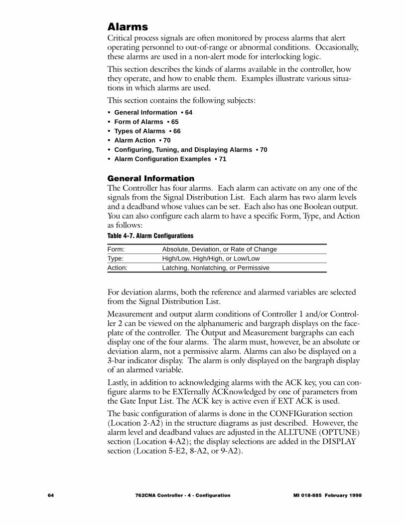
AlarmsCritical process signals are often monitored by process alarms that alert operating personnel to out-of-range or abnormal conditions. Occasionally, these alarms are used in a non-alert mode for interlocking logic.This section describes the kinds of alarms available in the controller, how they operate, and how to enable them. Examples illustrate various situa-tions in which alarms are used. This section contains the following subjects:• General Information • 64 • Form of Alarms • 65 • Types of Alarms • 66 • Alarm Action • 70 • Configuring, Tuning, and Displaying Alarms • 70 • Alarm Configuration Examples • 71
General InformationThe Controller has four alarms. Each alarm can activate on any one of the signals from the Signal Distribution List. Each alarm has two alarm levels and a deadband whose values can be set. Each also has one Boolean output. You can also configure each alarm to have a specific Form, Type, and Action as follows:
For deviation alarms, both the reference and alarmed variables are selected from the Signal Distribution List.Measurement and output alarm conditions of Controller 1 and/or Control-ler 2 can be viewed on the alphanumeric and bargraph displays on the face-plate of the controller. The Output and Measurement bargraphs can each display one of the four alarms. The alarm must, however, be an absolute or deviation alarm, not a permissive alarm. Alarms can also be displayed on a 3-bar indicator display. The alarm is only displayed on the bargraph display of an alarmed variable. Lastly, in addition to acknowledging alarms with the ACK key, you can con-figure alarms to be EXTernally ACKnowledged by one of parameters from the Gate Input List. The ACK key is active even if EXT ACK is used.The basic configuration of alarms is done in the CONFIGuration section (Location 2-A2) in the structure diagrams as just described. However, the alarm level and deadband values are adjusted in the ALLTUNE (OPTUNE) section (Location 4-A2); the display selections are added in the DISPLAY section (Location 5-E2, 8-A2, or 9-A2).
Table 4-7. Alarm Configurations
Form: Absolute, Deviation, or Rate of ChangeType: High/Low, High/High, or Low/LowAction: Latching, Nonlatching, or Permissive
64 762CNA Controller - 4 - Configuration MI 018-885 February 1998
Forms of AlarmsThere are three forms of alarms:• Absolute (ABS)• Deviation (DEV)• Rate of Change (ROC)
Absolute Alarms
An ABSolute alarm measures a variable relative to the zero process condi-tion; e.g., temperature measurement or level in a vessel. An ABSolute alarm has one input variable. This input is the monitored value that is compared with the configured alarm levels. When the attached monitored value exceeds the alarm level, an alarm condition occurs and the Boolean output associated with that alarm is set to True. In the case of Hi/Hi and Lo/Lo alarms (see “Types of Alarms” on page 66), the second alarm level (Level 1 for Hi/Hi, Level 2 for Lo/Lo) trips the Boolean output.Assign the input variable from the Signal Distribution List using the param-eter ATTACH at Location 5-B2 in the structure diagrams.
Deviation Alarms
A DEViation alarm monitors a process variable in relation to a reference variable. For example, you can use this form to determine how the mea-surement is performing in relation to the set point, or how “Flow 1” is per-forming in relation to “Flow 2”. A DEViation alarm has one input that is the monitored variable and one that is the reference variable. When the dif-ference between the two variables exceeds the configured alarm level, an alarm condition occurs and the Boolean output associated with that alarm is set to True.Select both monitored and reference variables from the Signal Distribution List. Assign the monitored variable using the parameter ATTACH and the reference variable using the parameter REF at Location 5-B2 in the struc-ture diagrams.
Rate of Change Alarm
Use a Rate-of-Change alarm when the change of a variable in an increment of time is important; i.e., the change in temperature per change in unit time in a reactor. Because of its infrequent use and greater complexity, the rate of change alarm is discussed in detail later in the “Additional Configuration Functions” section.
MI 018-885 February 1998 762CNA Controller - 4 - Configuration 65

Types of AlarmsThere are three types of alarms:• High/Low (HI/LO)• Low/Low (LO/LO)• High/High (HI/HI)Each alarm type uses a deadband (DB), a user adjustable parameter that prevents intermittent alarming when the monitored value hovers around the alarm levels.Examples of all alarm types are given on the following pages.
66 762CNA Controller - 4 - Configuration MI 018-885 February 1998
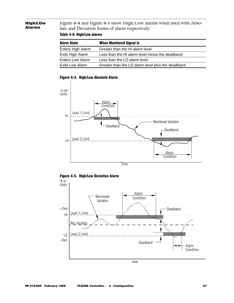
HIgh/LOw Alarms
Figure 4-4 and Figure 4-5 show High/Low alarms when used with Abso-lute and Deviation forms of alarm respectively.
Figure 4-4. High/Low Absolute Alarm
Figure 4-5. High/Low Deviation Alarm
Table 4-8. High/Low alarms
Alarm State When Monitored Signal Is
Enters High Alarm Greater than the HI alarm levelExits High Alarm Less than the HI alarm level minus the deadbandEnters Low Alarm Less than the LO alarm levelExits Low Alarm Greater than the LO alarm level plus the deadband
DeadbandDeadband
AlarmCondition
AlarmCondition
HI
LO Level 2 Limit
Level 1 Limit
Monitored Variable
% ORUnits
Time
TIME
% orUnits
+Dev.
-Dev.
AlarmCondition
Ref. Variable
MonitoredVariable
Deadband
Deadband
Level 2 Limit
Level 1 Limit
AlarmCondition
HI
LO
MI 018-885 February 1998 762CNA Controller - 4 - Configuration 67
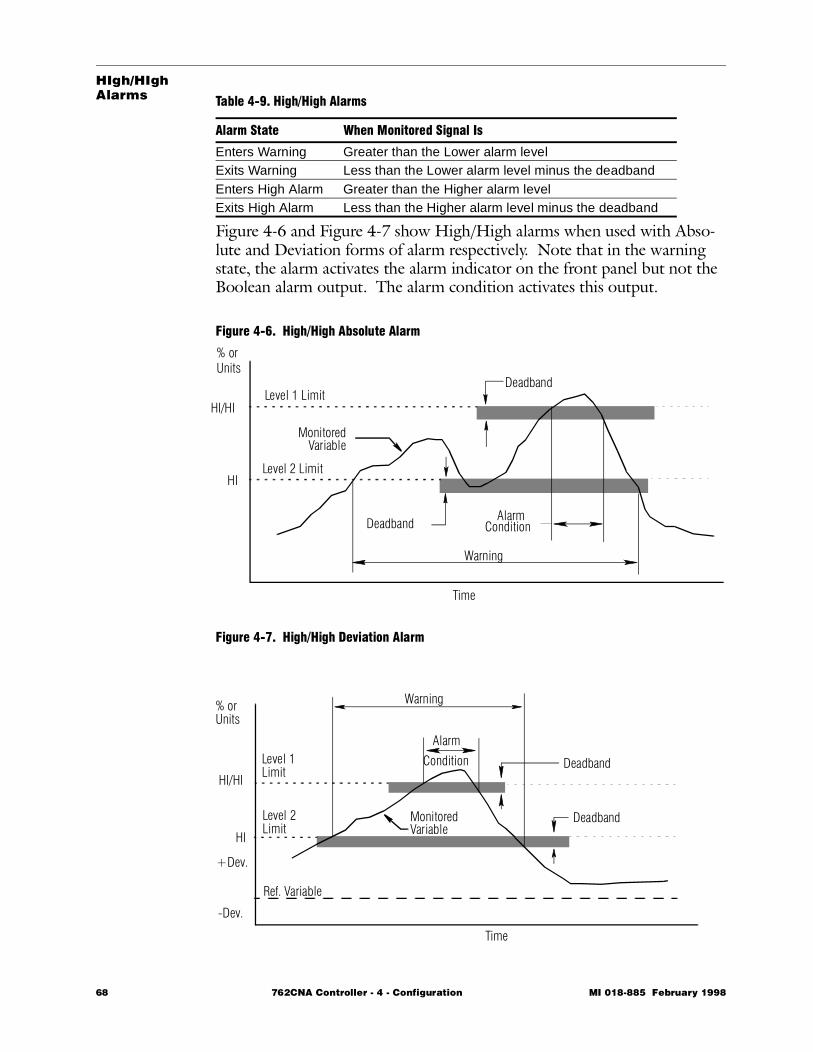
HIgh/HIgh Alarms
Figure 4-6 and Figure 4-7 show High/High alarms when used with Abso-lute and Deviation forms of alarm respectively. Note that in the warning state, the alarm activates the alarm indicator on the front panel but not the Boolean alarm output. The alarm condition activates this output.
Figure 4-6. High/High Absolute Alarm
Figure 4-7. High/High Deviation Alarm
Table 4-9. High/High Alarms
Alarm State When Monitored Signal Is
Enters Warning Greater than the Lower alarm levelExits Warning Less than the Lower alarm level minus the deadbandEnters High Alarm Greater than the Higher alarm levelExits High Alarm Less than the Higher alarm level minus the deadband
Level 1 Limit
Level 2 Limit
HI/HI
HI
Deadband
Deadband
Warning
AlarmCondition
MonitoredVariable
Time
% orUnits
Time
% orUnits
Condition
Alarm
Warning
Level 1Limit
Level 2Limit
MonitoredVariable
Ref. Variable
-Dev.
+Dev.
Deadband
Deadband
HI/HI
HI
68 762CNA Controller - 4 - Configuration MI 018-885 February 1998
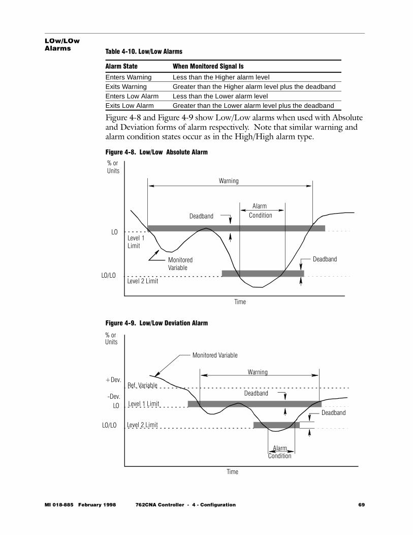
LOw/LOw Alarms
Figure 4-8 and Figure 4-9 show Low/Low alarms when used with Absolute and Deviation forms of alarm respectively. Note that similar warning and alarm condition states occur as in the High/High alarm type.
Figure 4-8. Low/Low Absolute Alarm
Figure 4-9. Low/Low Deviation Alarm
Table 4-10. Low/Low Alarms
Alarm State When Monitored Signal Is
Enters Warning Less than the Higher alarm levelExits Warning Greater than the Higher alarm level plus the deadbandEnters Low Alarm Less than the Lower alarm levelExits Low Alarm Greater than the Lower alarm level plus the deadband
Warning
AlarmCondition
Level 2 Limit
Level 1Limit
LO
LO/LO
Time
% orUnits
MonitoredVariable
Deadband
Deadband
Time
% orUnits
Level 1 Limit
Level 2 Limit
Ref. Variable+Dev.
-Dev.
Warning
AlarmCondition
Monitored Variable
Deadband
DeadbandLO
LO/LO
MI 018-885 February 1998 762CNA Controller - 4 - Configuration 69
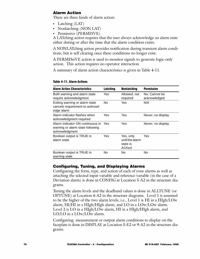
Alarm ActionThere are three kinds of alarm action:• Latching (LAT)• Nonlatching (NON LAT)• Permissive (PERMISVE)A LATching action requires that the user always acknowledge an alarm state either during or after the time that the alarm condition exists.A NONLATching action provides notification during transient alarm condi-tions, but is self clearing once these conditions no longer exist.A PERMISsiVE action is used to monitor signals to generate logic-only action. This action requires no operator interaction.A summary of alarm action characteristics is given in Table 4-11.
Configuring, Tuning, and Displaying AlarmsConfiguring the form, type, and action of each of your alarms as well as attaching the selected input variable and reference variable (in the case of a Deviation alarm) is done in CONFIG at Location 5-A2 in the structure dia-grams.Tuning the alarm levels and the deadband values is done in ALLTUNE (or OPTUNE) at Location 4-A2 in the structure diagrams. Level 1 is assumed to be the higher of the two alarm levels; i.e., Level 1 is HI in a HIgh/LOw alarm, HI/HI in a HIgh/HIgh alarm, and LO in a LOw/LOw alarm. Level 2 is LO in a HIgh/LOw alarm, HI in a HIgh/HIgh alarm, and LO/LO in a LOw/LOw alarm.Configuring measurement or output alarm conditions to display on the faceplate is done in DISPLAY at Location 5-E2 or 9-A2 in the structure dia-grams.
Table 4-11. Alarm Actions
Alarm Action Characteristics Latching Nonlatching Permissive
Both warning and alarm staterequire acknowledgment
Yes Allowed, not required
No; Cannot beacknowledged
Exiting warning or alarm statecancels requirement to acknowl-edge alarm
No Yes N/A
Alarm indicator flashes whenacknowledgment required
Yes Yes Never; no display
Alarm indicator ON continuous in warning or alarm state following acknowledgment
Yes Yes Never; no display
Boolean output is TRUE inalarm state
Yes Yes, only until the alarm state is ACKed
Yes
Boolean output is TRUE in warning state
No No No
70 762CNA Controller - 4 - Configuration MI 018-885 February 1998
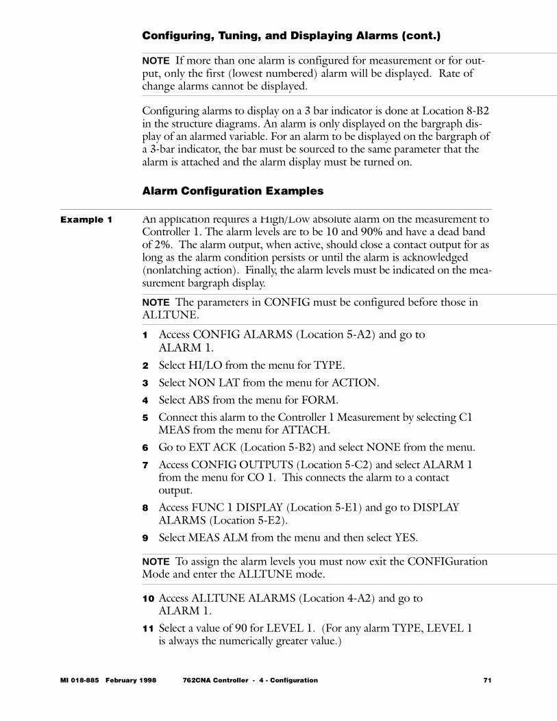
Configuring, Tuning, and Displaying Alarms (cont.)
NOTE If more than one alarm is configured for measurement or for out-put, only the first (lowest numbered) alarm will be displayed. Rate of change alarms cannot be displayed.
Configuring alarms to display on a 3 bar indicator is done at Location 8-B2 in the structure diagrams. An alarm is only displayed on the bargraph dis-play of an alarmed variable. For an alarm to be displayed on the bargraph of a 3-bar indicator, the bar must be sourced to the same parameter that the alarm is attached and the alarm display must be turned on.
Alarm Configuration Examples
Example 1 An application requires a High/Low absolute alarm on the measurement to Controller 1. The alarm levels are to be 10 and 90% and have a dead band of 2%. The alarm output, when active, should close a contact output for as long as the alarm condition persists or until the alarm is acknowledged (nonlatching action). Finally, the alarm levels must be indicated on the mea-surement bargraph display.
NOTE The parameters in CONFIG must be configured before those in ALLTUNE.
1 Access CONFIG ALARMS (Location 5-A2) and go to ALARM 1.
2 Select HI/LO from the menu for TYPE.3 Select NON LAT from the menu for ACTION.4 Select ABS from the menu for FORM.5 Connect this alarm to the Controller 1 Measurement by selecting C1
MEAS from the menu for ATTACH.6 Go to EXT ACK (Location 5-B2) and select NONE from the menu.7 Access CONFIG OUTPUTS (Location 5-C2) and select ALARM 1
from the menu for CO 1. This connects the alarm to a contact output.
8 Access FUNC 1 DISPLAY (Location 5-E1) and go to DISPLAY ALARMS (Location 5-E2).
9 Select MEAS ALM from the menu and then select YES.
NOTE To assign the alarm levels you must now exit the CONFIGuration Mode and enter the ALLTUNE mode.
10 Access ALLTUNE ALARMS (Location 4-A2) and go to ALARM 1.
11 Select a value of 90 for LEVEL 1. (For any alarm TYPE, LEVEL 1 is always the numerically greater value.)
MI 018-885 February 1998 762CNA Controller - 4 - Configuration 71
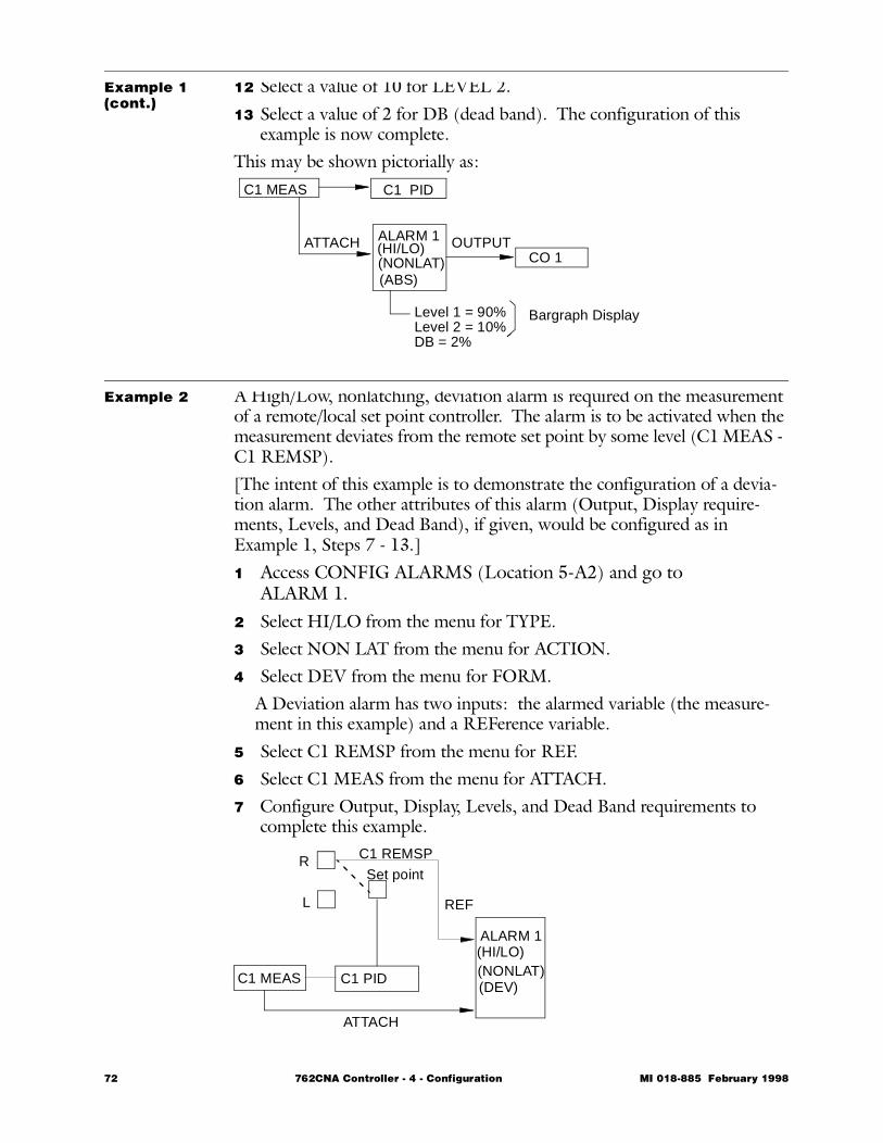
Example 1 (cont.)
12 Select a value of 10 for LEVEL 2.13 Select a value of 2 for DB (dead band). The configuration of this
example is now complete.This may be shown pictorially as:
Example 2 A High/Low, nonlatching, deviation alarm is required on the measurement of a remote/local set point controller. The alarm is to be activated when the measurement deviates from the remote set point by some level (C1 MEAS - C1 REMSP).[The intent of this example is to demonstrate the configuration of a devia-tion alarm. The other attributes of this alarm (Output, Display require-ments, Levels, and Dead Band), if given, would be configured as in Example 1, Steps 7 - 13.]1 Access CONFIG ALARMS (Location 5-A2) and go to
ALARM 1.2 Select HI/LO from the menu for TYPE.3 Select NON LAT from the menu for ACTION.4 Select DEV from the menu for FORM.
A Deviation alarm has two inputs: the alarmed variable (the measure-ment in this example) and a REFerence variable.
5 Select C1 REMSP from the menu for REF.6 Select C1 MEAS from the menu for ATTACH.7 Configure Output, Display, Levels, and Dead Band requirements to
complete this example.
C1 MEAS C1 PID
ALARM 1
(ABS)(NONLAT)(HI/LO)ATTACH OUTPUT
CO 1
Level 1 = 90%Level 2 = 10%DB = 2%
Bargraph Display
C1 PID
ALARM 1
(DEV)(NONLAT)(HI/LO)
R
L
C1 MEAS
Set point
REF
ATTACH
C1 REMSP
72 762CNA Controller - 4 - Configuration MI 018-885 February 1998
Example 3 The output state of a deviation alarm determines whether the EXACT state is ON or OFF and whether Contact Output 2 is open or closed.
NOTE For this example assume that ALARM 1 is the alarm in question and that its configuration has been completed. Further assume that Con-troller 1 has been configured to the point of selecting the TYPE of con-trol.
1 Access CONFIG FUNC 1 (Location 5-A1) and select EXACT.2 At EXACT SW in Location 5-G3, select ALARM 1 from the menu.
This selection means that EXACT is activated (turned ON) when ALARM 1 is in the alarm state.
3 Access CONFIG OUTPUTS (Location 5-C2) and select CO 2.4 Select ALARM 1 from the menu for CO 2. This selection means
that Contact Output 2 is closed when ALARM 1 is in the alarm state. The configuration of this example is now complete.
MI 018-885 February 1998 762CNA Controller - 4 - Configuration 73
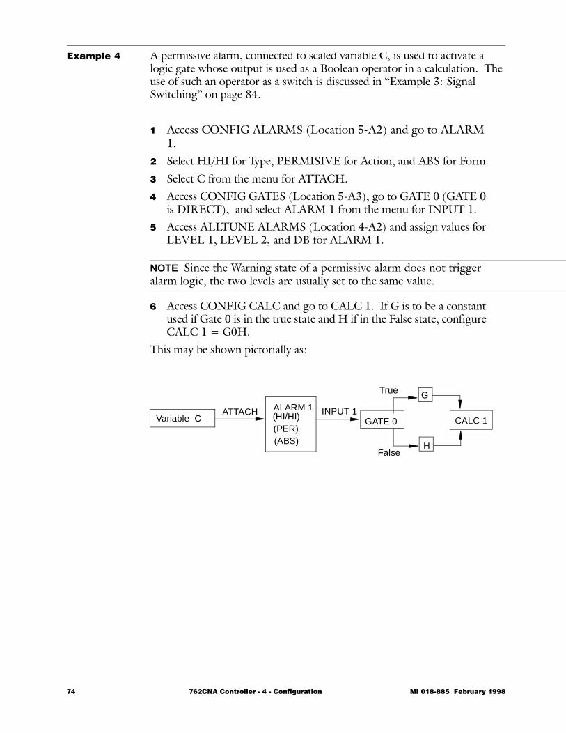
Example 4 A permissive alarm, connected to scaled variable C, is used to activate a logic gate whose output is used as a Boolean operator in a calculation. The use of such an operator as a switch is discussed in “Example 3: Signal Switching” on page 84.
1 Access CONFIG ALARMS (Location 5-A2) and go to ALARM 1.
2 Select HI/HI for Type, PERMISIVE for Action, and ABS for Form.3 Select C from the menu for ATTACH.4 Access CONFIG GATES (Location 5-A3), go to GATE 0 (GATE 0
is DIRECT), and select ALARM 1 from the menu for INPUT 1.5 Access ALLTUNE ALARMS (Location 4-A2) and assign values for
LEVEL 1, LEVEL 2, and DB for ALARM 1.
NOTE Since the Warning state of a permissive alarm does not trigger alarm logic, the two levels are usually set to the same value.
6 Access CONFIG CALC and go to CALC 1. If G is to be a constant used if Gate 0 is in the true state and H if in the False state, configure CALC 1 = G0H.
This may be shown pictorially as:
Variable CATTACH ALARM 1
(ABS)(PER)(HI/HI) GATE 0 CALC 1
G
H
INPUT 1
True
False
74 762CNA Controller - 4 - Configuration MI 018-885 February 1998
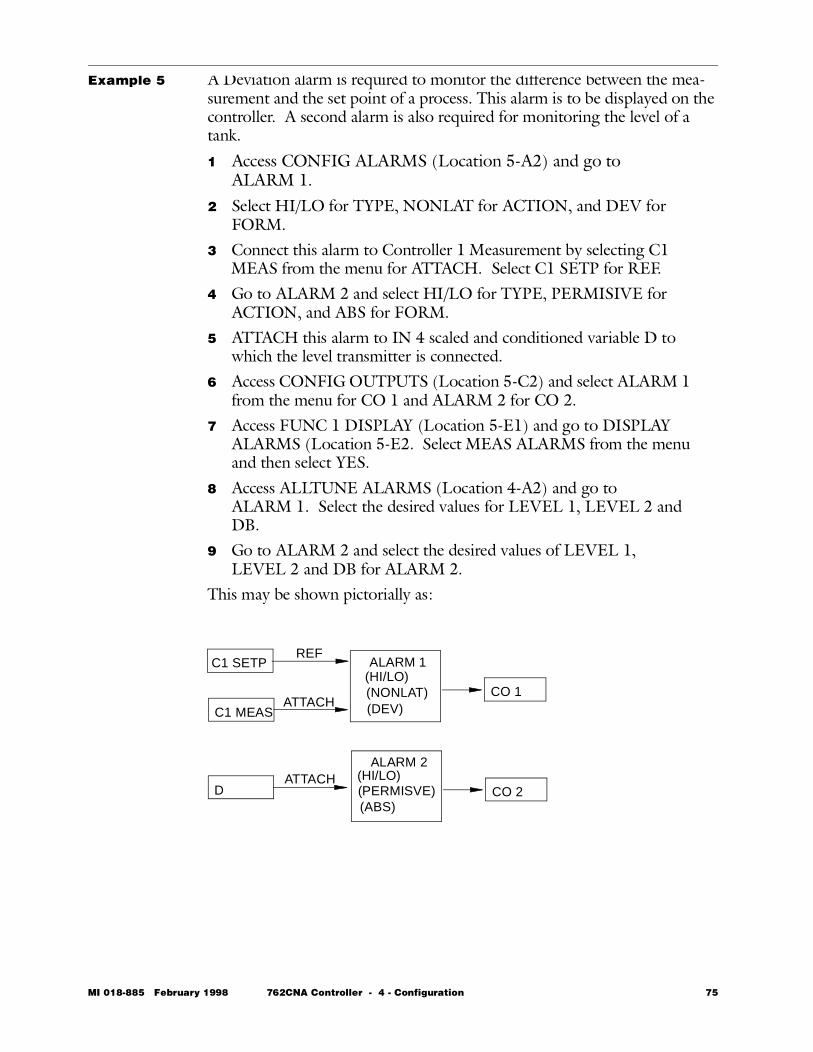
Example 5 A Deviation alarm is required to monitor the difference between the mea-surement and the set point of a process. This alarm is to be displayed on the controller. A second alarm is also required for monitoring the level of a tank.
1 Access CONFIG ALARMS (Location 5-A2) and go to ALARM 1.
2 Select HI/LO for TYPE, NONLAT for ACTION, and DEV for FORM.
3 Connect this alarm to Controller 1 Measurement by selecting C1 MEAS from the menu for ATTACH. Select C1 SETP for REF.
4 Go to ALARM 2 and select HI/LO for TYPE, PERMISIVE for ACTION, and ABS for FORM.
5 ATTACH this alarm to IN 4 scaled and conditioned variable D to which the level transmitter is connected.
6 Access CONFIG OUTPUTS (Location 5-C2) and select ALARM 1 from the menu for CO 1 and ALARM 2 for CO 2.
7 Access FUNC 1 DISPLAY (Location 5-E1) and go to DISPLAY ALARMS (Location 5-E2. Select MEAS ALARMS from the menu and then select YES.
8 Access ALLTUNE ALARMS (Location 4-A2) and go to ALARM 1. Select the desired values for LEVEL 1, LEVEL 2 and DB.
9 Go to ALARM 2 and select the desired values of LEVEL 1, LEVEL 2 and DB for ALARM 2.
This may be shown pictorially as:
C1 SETP
C1 MEAS
ALARM 1REF
ATTACHCO 1
(DEV)(NONLAT)(HI/LO)
D
ALARM 2ATTACH
CO 2(ABS)(PERMISVE)(HI/LO)
MI 018-885 February 1998 762CNA Controller - 4 - Configuration 75
Alternate Station ConfigurationsThis section contains the following subjects:• Dual Controller • 76 • Cascade Controller • 76 • Auto Selector Controller • 78 • Auto Manual Station • 79 • Indicator Station • 79
Dual ControllerYou can use the 762CNA as two controllers with independent control strat-egies. All control functions (P, I, PI, PD, PID, and EXACT) are available to each loop. Specify the STRATEGY as TWO FUNC at Location 5-B1 in the structure diagrams. Then configure the first loop in CONFIG FUNC 1 and the second loop at CONFIG FUNC 2, both at Location 5-A1 in the structure diagrams.
Cascade ControllerYou can also configure the 762CNA to operate as a cascade controller. As such, the output of Controller 1 (primary controller) is used as the set point or ratio input of Controller 2 (secondary controller). The configuration allows bumpless transfers between auto/manual modes and between remote/local set point modes. To configure the 762CNA as a cascade con-troller, specify the STRATEGY as CASCADE at Location 5-B1 in the struc-ture diagrams. Then configure the primary controller at FUNC 1 and the secondary controller at FUNC 2, both at Location 5-A1 in the structure diagrams.
Example A single station cascade controller is required as shown in Figure 4-10. As steam is drawn from the header, the pressure drops, reducing the flow to the heat exchanger and causing fluctuations in heated liquid temperature. By measuring the steam flow, the secondary controller can quickly adjust the steam flow to compensate for pressure fluctuations, thus minimizing the temperature variation seen in the heated fluid.
76 762CNA Controller - 4 - Configuration MI 018-885 February 1998

Example(cont.)
Figure 4-10. Single Cascade Controller Example
The primary is a temperature controller (RTD Option is used) and the sec-ondary is a flow controller. The integral feedback (INT FBK) to the pri-mary is the measurement of the secondary.For this example, start with configuration of STRATEGY to CASCADE. Next, configure the primary, then the secondary, and finally the inputs.1 Access CONFIG STRATEGY (Location 5-A1) and select CAS-
CADE from the menu.2 Access CONFIG FUNC 1 and go to DISPLAY (Location 5-E1).3 At this point you would configure MEAS, SP TYPE as TEMP, and
then the SCALE, ENG UNiTS, and range (URV and LRV), if given, in the example at Location 5-E2 and 5-E3.
4 Access CONFIG FUNC 1 and go to MEAS (Location 5-G2). Select LINEAR from the menu for FORMAT.
5 Select A from the menu for SOURCE. INPUT 1 must be used for an RTD and A is INPUT 1 after signal conditioning.
6 Access CONFIG FUNC 2 and go to DISPLAY (Location 5-E1).7 At MEAS, SP (Location 5-E2), go to TYPE and select LINEAR.8 Access CONFIG FUNC 2 and go to MEAS (Location 5-G2).
Select B from the menu for SOURCE. (Flow Measurement)9 Access CONFIG INPUTS and go to INPUTS A (Location 5-B2).10 Go to FORMAT and select LINEAR from the menu.11 Go to INPUTS B and repeat Step 10.This completes the configuration of the requirements given for this example.
TIC
FT
FICC2 MEAS
C2 REMSP
C1 OUT C1 MEAS
INT FBK
RTD
Heat Exchanger
Cold Liquid
Heated Liquid
Steam Header
MI 018-885 February 1998 762CNA Controller - 4 - Configuration 77
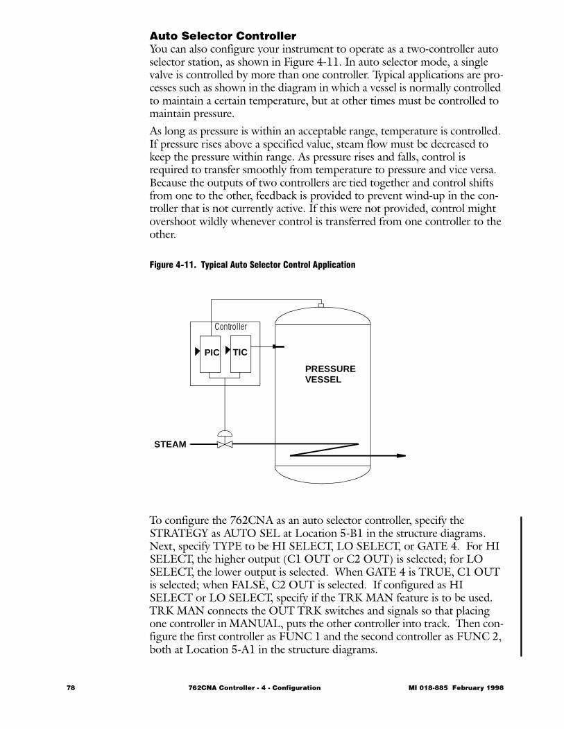
Auto Selector ControllerYou can also configure your instrument to operate as a two-controller auto selector station, as shown in Figure 4-11. In auto selector mode, a single valve is controlled by more than one controller. Typical applications are pro-cesses such as shown in the diagram in which a vessel is normally controlled to maintain a certain temperature, but at other times must be controlled to maintain pressure. As long as pressure is within an acceptable range, temperature is controlled. If pressure rises above a specified value, steam flow must be decreased to keep the pressure within range. As pressure rises and falls, control is required to transfer smoothly from temperature to pressure and vice versa. Because the outputs of two controllers are tied together and control shifts from one to the other, feedback is provided to prevent wind-up in the con-troller that is not currently active. If this were not provided, control might overshoot wildly whenever control is transferred from one controller to the other.
Figure 4-11. Typical Auto Selector Control Application
To configure the 762CNA as an auto selector controller, specify the STRATEGY as AUTO SEL at Location 5-B1 in the structure diagrams. Next, specify TYPE to be HI SELECT, LO SELECT, or GATE 4. For HI SELECT, the higher output (C1 OUT or C2 OUT) is selected; for LO SELECT, the lower output is selected. When GATE 4 is TRUE, C1 OUT is selected; when FALSE, C2 OUT is selected. If configured as HI SELECT or LO SELECT, specify if the TRK MAN feature is to be used. TRK MAN connects the OUT TRK switches and signals so that placing one controller in MANUAL, puts the other controller into track. Then con-figure the first controller as FUNC 1 and the second controller as FUNC 2, both at Location 5-A1 in the structure diagrams.
PRESSUREVESSEL
TICPIC
STEAM
Controller
78 762CNA Controller - 4 - Configuration MI 018-885 February 1998
Auto/Manual StationYou may also configure the 762CNA as one or two auto/manual transfer stations. If a controller or indicator is configured, only one auto/manual station is available. Configuring your instrument as an auto/manual station will enable you to manually select either an incoming signal or a manually-adjusted signal and send the results to a valve or other receiver. This allows you to interrupt a signal that is sourced from another device and manually take control of it. In addition, all of the supporting functions available in the controller (e.g., calculation blocks) are available in the auto/manual station.To configure the 762CNA as an auto/ manual station, specify the STRAT-EGY as ONE FUNC or TWO FUNC at Location 5-A1 in the structure diagrams. Then configure FUNC 1, FUNC 2, or both as A/M STN at Location 5-B1 in the structure diagrams. From there go to Location 9 to configure the details of your auto/manual station. Configure the set point display type to NONE to eliminate the normal controller set point function and bargraph.
NOTE Check the BIAS under OPTUNE or ALLTUNE, as it affects the output when in AUTO mode. For proper operation as an A/M Station, the BIAS should be set to zero.
Indicator StationYou can also use the 762CNA as one or two 3-variable indicators. Each variable has its own bargraph, digital engineering units, and loop tag. If a controller or auto manual station is configured, only one 3-variable indica-tor is available. To configure the 762CNA as a 3-variable indicator:1 Specify the STRATEGY as ONE FUNC or TWO FUNC at
Location 5-B1 in the structure diagrams.2 Configure FUNC 1, FUNC 2, or both as 3 BAR IND at
Location 5-B1 in the structure diagrams.3 Go to Location 8 to configure the details of each of the bargraphs of
your 3-variable indicator.4 Specify a 9-character loopTAG. If a blank TAG line is desired, then
blank entries must be made.5 Specify the TYPE of indication (LINEAR or TEMP), ENG UNiTS
and range (URV and LRV). If you select TEMPerature, specify the SCALE as IEC 100 or SAMA 100 for an RTD input or T/C J, T/C K, or T/C E for a temperature transmitter thermocouple input. Specify the ENG UNiTS as DEG F or DEG C.
6 Specify the SOURCE of the variable indicated from the Signal Dis-tribution List. A SOURCE selection of NONE blanks the respec-tive bargraph and its digital display.
7 Specify for each variable, whether or not alarms should be displayed at Location 8-B2. For an alarm to appear on a given bargraph, there must be an alarm ATTACHED to the SOURCE of that bargraph. Alarms are configured at Location 5-A2.
MI 018-885 February 1998 762CNA Controller - 4 - Configuration 79
Additional Configuration FunctionsThis section contains the following subjects:• Logic Gates • 81 • Calculations • 82 • Dynamic Compensation • 86 • Totalizers • 89 • Set Point • 91 • Set Point Limits • 93 • Ratio Control • 93 • Output Summing and Multiplying • 94 • Output Tracking • 94 • Split Range Output • 94 • Output Limits • 98 • Output Action • 99 • Output Upon Restart (STARTUP) • 99 • Output Reverse • 99 • Output Bargraph • 99 • Characterizers • 100 • Nonlinear Control • 100 • pH Display • 100 • Serial Communications • 101 • Toggle • 102 • Batch Control • 103 • Integral Feedback • 103 • Rate of Change Alarms • 104
80 762CNA Controller - 4 - Configuration MI 018-885 February 1998
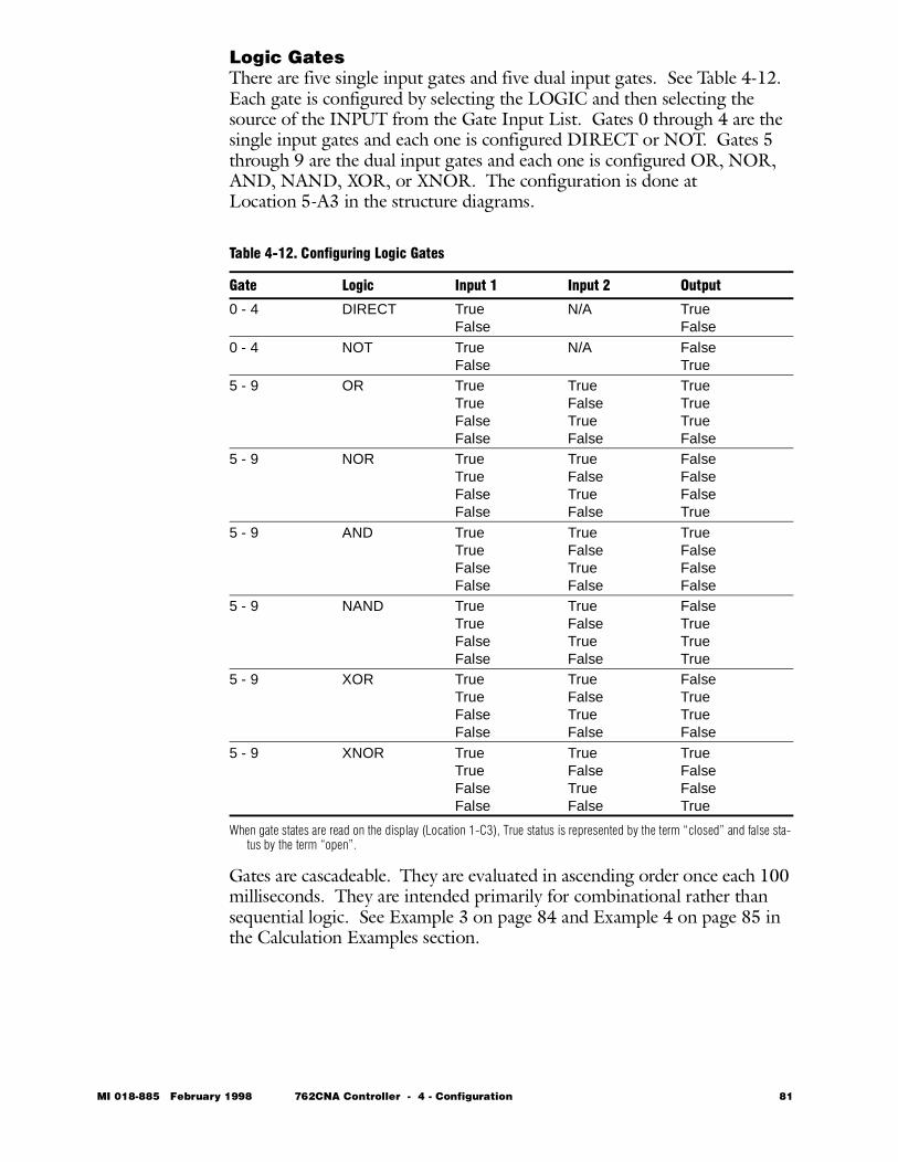
Logic GatesThere are five single input gates and five dual input gates. See Table 4-12. Each gate is configured by selecting the LOGIC and then selecting the source of the INPUT from the Gate Input List. Gates 0 through 4 are the single input gates and each one is configured DIRECT or NOT. Gates 5 through 9 are the dual input gates and each one is configured OR, NOR, AND, NAND, XOR, or XNOR. The configuration is done at Location 5-A3 in the structure diagrams.
When gate states are read on the display (Location 1-C3), True status is represented by the term “closed” and false sta-tus by the term “open”.
Gates are cascadeable. They are evaluated in ascending order once each 100 milliseconds. They are intended primarily for combinational rather than sequential logic. See Example 3 on page 84 and Example 4 on page 85 in the Calculation Examples section.
Table 4-12. Configuring Logic Gates
Gate Logic Input 1 Input 2 Output
0 - 4 DIRECT TrueFalse
N/A TrueFalse
0 - 4 NOT TrueFalse
N/A FalseTrue
5 - 9 OR TrueTrueFalseFalse
TrueFalseTrueFalse
TrueTrueTrueFalse
5 - 9 NOR TrueTrueFalseFalse
TrueFalseTrueFalse
FalseFalseFalseTrue
5 - 9 AND TrueTrueFalseFalse
TrueFalseTrueFalse
TrueFalseFalseFalse
5 - 9 NAND TrueTrueFalseFalse
TrueFalseTrueFalse
FalseTrueTrueTrue
5 - 9 XOR TrueTrueFalseFalse
TrueFalseTrueFalse
FalseTrueTrueFalse
5 - 9 XNOR TrueTrueFalseFalse
TrueFalseTrueFalse
TrueFalseFalseTrue
MI 018-885 February 1998 762CNA Controller - 4 - Configuration 81
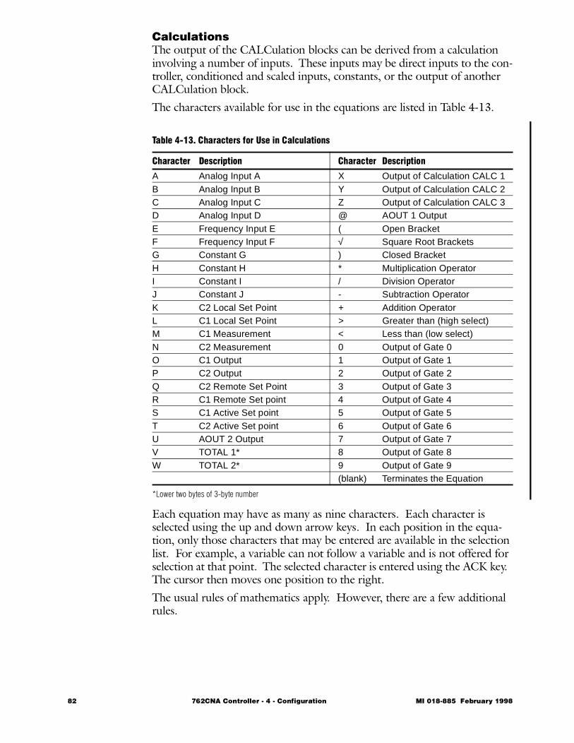
CalculationsThe output of the CALCulation blocks can be derived from a calculation involving a number of inputs. These inputs may be direct inputs to the con-troller, conditioned and scaled inputs, constants, or the output of another CALCulation block.The characters available for use in the equations are listed in Table 4-13.
*Lower two bytes of 3-byte number
Each equation may have as many as nine characters. Each character is selected using the up and down arrow keys. In each position in the equa-tion, only those characters that may be entered are available in the selection list. For example, a variable can not follow a variable and is not offered for selection at that point. The selected character is entered using the ACK key. The cursor then moves one position to the right.The usual rules of mathematics apply. However, there are a few additional rules.
Table 4-13. Characters for Use in Calculations
Character Description Character Description
A Analog Input A X Output of Calculation CALC 1B Analog Input B Y Output of Calculation CALC 2C Analog Input C Z Output of Calculation CALC 3D Analog Input D @ AOUT 1 OutputE Frequency Input E ( Open BracketF Frequency Input F √ Square Root BracketsG Constant G ) Closed BracketH Constant H * Multiplication OperatorI Constant I / Division OperatorJ Constant J - Subtraction OperatorK C2 Local Set Point + Addition OperatorL C1 Local Set Point > Greater than (high select)M C1 Measurement < Less than (low select)N C2 Measurement 0 Output of Gate 0O C1 Output 1 Output of Gate 1P C2 Output 2 Output of Gate 2Q C2 Remote Set Point 3 Output of Gate 3R C1 Remote Set point 4 Output of Gate 4S C1 Active Set point 5 Output of Gate 5T C2 Active Set point 6 Output of Gate 6U AOUT 2 Output 7 Output of Gate 7V TOTAL 1* 8 Output of Gate 8W TOTAL 2* 9 Output of Gate 9
(blank) Terminates the Equation
82 762CNA Controller - 4 - Configuration MI 018-885 February 1998
Calculations (cont.)1 To save space, if there is an open bracket with no associated closed
bracket, there is an implied closed bracket to the right of the right-most character. Similarly, if there is a closed bracket with no asso-ciated open bracket, there is an implied open bracket to the left of the leftmost character. For example, (A/B)*(D+H) has 11 char-acters and thus exceeds the limit of nine. This can be made accept-able by rewriting the equation as A/B)*(D+H.
2 A square root is treated like an open bracket during evaluation except that the square root is taken after evaluating the contents of the bracket. For example, in the expression A * √ (B + C), B is added to C, then the square root of the sum is taken and multiplied times A.
3 The left argument of a gate is selected in the True state and the right argument in the False state. For example, in the equation CALC 1 = A0B, CALC 1 = A if the output of Gate 0 is True but CALC 1 = B if the output of Gate 0 is False. Thus gates can perform switch func-tions.
4 The order of evaluation is:Contents of a bracket pair
All gates (switches) left to right
All selectors left to right
All multiplications and divisions left to right
All additions and subtractions left to right
The SEL key will move the cursor one position to the left. If the SEL key is pressed when the cursor is in the leftmost position, the equation entry is aborted. If in going back to make a change, the up or down arrow key is used to select a different category from the current selected character, the characters to the right of the cursor position are blanked.
Several examples are given below to help you understand how to configure this powerful function.
Example 1: Simple Math
A controller is used for pressure-temperature compensated head flow. The equation measurement = √hP/T applies. The head is INput 1; the pressure, INput 2; and the temperature, INput 3. Because the inputs and output are expressed in percent of range, a scaling factor, G, is required. Its value is set in ALLTUNE. To enter this, choose CALC 1 (or CALC 2 or CALC 3) to be the calcula-tion. The scaled INputs 1, 2, and 3 are A, B, and C respectively.
MI 018-885 February 1998 762CNA Controller - 4 - Configuration 83
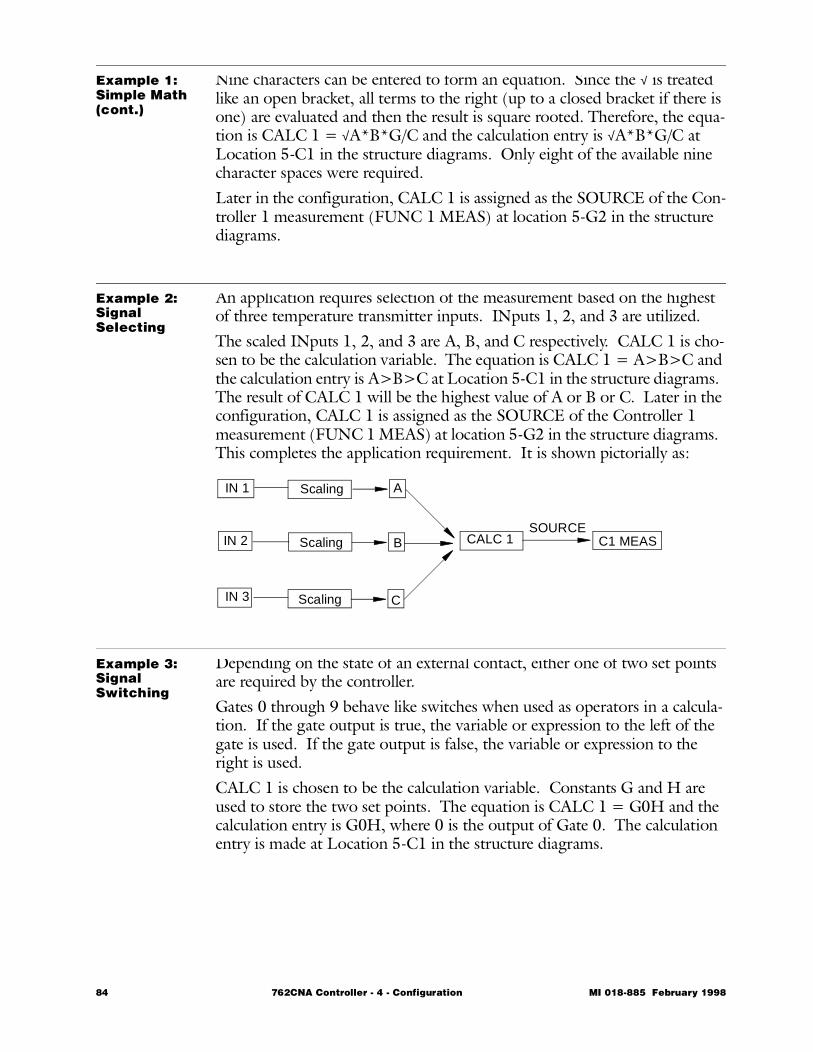
Example 1: Simple Math(cont.)
Nine characters can be entered to form an equation. Since the √ is treated like an open bracket, all terms to the right (up to a closed bracket if there is one) are evaluated and then the result is square rooted. Therefore, the equa-tion is CALC 1 = √A*B*G/C and the calculation entry is √A*B*G/C at Location 5-C1 in the structure diagrams. Only eight of the available nine character spaces were required.Later in the configuration, CALC 1 is assigned as the SOURCE of the Con-troller 1 measurement (FUNC 1 MEAS) at location 5-G2 in the structure diagrams.
Example 2: Signal Selecting
An application requires selection of the measurement based on the highest of three temperature transmitter inputs. INputs 1, 2, and 3 are utilized.The scaled INputs 1, 2, and 3 are A, B, and C respectively. CALC 1 is cho-sen to be the calculation variable. The equation is CALC 1 = A>B>C and the calculation entry is A>B>C at Location 5-C1 in the structure diagrams. The result of CALC 1 will be the highest value of A or B or C. Later in the configuration, CALC 1 is assigned as the SOURCE of the Controller 1 measurement (FUNC 1 MEAS) at location 5-G2 in the structure diagrams. This completes the application requirement. It is shown pictorially as:
Example 3: Signal Switching
Depending on the state of an external contact, either one of two set points are required by the controller.Gates 0 through 9 behave like switches when used as operators in a calcula-tion. If the gate output is true, the variable or expression to the left of the gate is used. If the gate output is false, the variable or expression to the right is used.CALC 1 is chosen to be the calculation variable. Constants G and H are used to store the two set points. The equation is CALC 1 = G0H and the calculation entry is G0H, where 0 is the output of Gate 0. The calculation entry is made at Location 5-C1 in the structure diagrams.
IN 1
IN 2
IN 3
A
B
C
CALC 1 C1 MEASSOURCE
Scaling
Scaling
Scaling
84 762CNA Controller - 4 - Configuration MI 018-885 February 1998
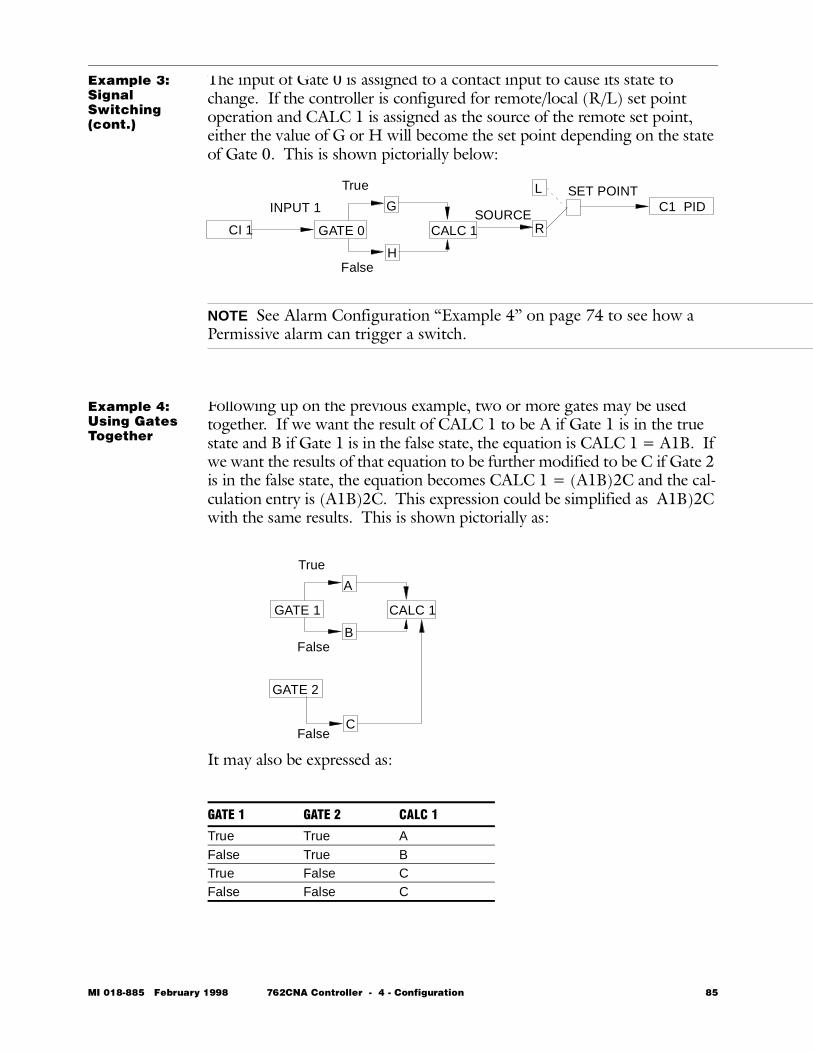
Example 3: Signal Switching(cont.)
The input of Gate 0 is assigned to a contact input to cause its state to change. If the controller is configured for remote/local (R/L) set point operation and CALC 1 is assigned as the source of the remote set point, either the value of G or H will become the set point depending on the state of Gate 0. This is shown pictorially below:
NOTE See Alarm Configuration “Example 4” on page 74 to see how a Permissive alarm can trigger a switch.
Example 4: Using Gates Together
Following up on the previous example, two or more gates may be used together. If we want the result of CALC 1 to be A if Gate 1 is in the true state and B if Gate 1 is in the false state, the equation is CALC 1 = A1B. If we want the results of that equation to be further modified to be C if Gate 2 is in the false state, the equation becomes CALC 1 = (A1B)2C and the cal-culation entry is (A1B)2C. This expression could be simplified as A1B)2C with the same results. This is shown pictorially as:
It may also be expressed as:
L
RSOURCE
C1 PIDG
H
CI 1 CALC 1
INPUT 1
GATE 0
SET POINTTrue
False
GATE 1 GATE 2 CALC 1
True True AFalse True BTrue False CFalse False C
A
B
CALC 1GATE 1
True
False
GATE 2
CFalse
MI 018-885 February 1998 762CNA Controller - 4 - Configuration 85
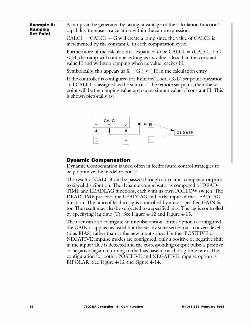
Example 5: Ramping Set Point
A ramp can be generated by taking advantage of the calculation function’s capability to reuse a calculation within the same expression.CALC1 = CALC1 + G will create a ramp since the value of CALC1 is incremented by the constant G in each computation cycle. Furthermore, if the calculation is expanded to be CALC1 = (CALC1 + G) < H, the ramp will continue as long as its value is less than the constant value H and will stop ramping when its value reaches H.Symbolically, this appears as X + G ) < ( H in the calculation entry. If the controller is configured for Remote/ Local (R/L) set point operation and CALC1 is assigned as the source of the remote set point, then the set point will be the ramping value up to a maximum value of constant H. This is shown pictorially as:
Dynamic CompensationDynamic Compensation is used often in feedforward control strategies to help optimize the model response.The result of CALC 3 can be passed through a dynamic compensator prior to signal distribution. The dynamic compensator is composed of DEAD-TIME and LEADLAG functions, each with its own FOLLOW switch. The DEADTIME precedes the LEADLAG and is the input of the LEADLAG function. The ratio of lead to lag is controlled by a user specified GAIN fac-tor. The result may also be subjected to a specified bias. The lag is controlled by specifying lag time (T). See Figure 4-12 and Figure 4-13.The user can also configure an impulse option. If this option is configured, the GAIN is applied as usual but the steady state settles out to a zero level (plus BIAS) rather than at the new input value. If either POSITIVE or NEGATIVE impulse modes are configured, only a positive or negative shift in the input value is detected and the corresponding output pulse is positive or negative (again returning to the bias baseline at the lag time rate). The configuration for both a POSITIVE and NEGATIVE impulse option is BIPOLAR. See Figure 4-12 and Figure 4-14.
+CALC 1
G
R
LH
C1 SETP
<+
86 762CNA Controller - 4 - Configuration MI 018-885 February 1998
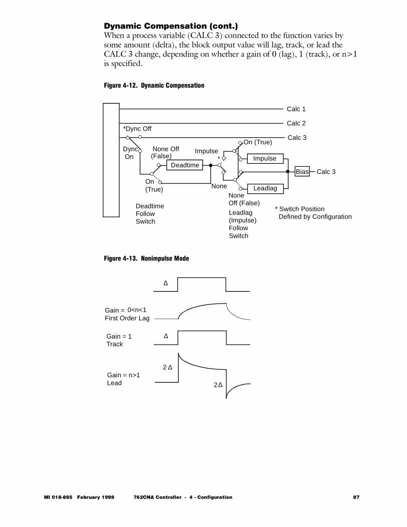
Dynamic Compensation (cont.)When a process variable (CALC 3) connected to the function varies by some amount (delta), the block output value will lag, track, or lead the CALC 3 change, depending on whether a gain of 0 (lag), 1 (track), or n>1 is specified.
Figure 4-12. Dynamic Compensation
Figure 4-13. Nonimpulse Mode
*Dync Off
Impulse
Leadlag
BiasDeadtime
Dync On
Impulse*
Calc 3
On (True)None Off(False)
NoneOn(True)
NoneOff (False)Deadtime
FollowSwitch
Leadlag(Impulse)FollowSwitch
* Switch Position
Calc 1
Calc 2
Calc 3
Defined by Configuration
∆
∆
∆2
2
Gain =First Order Lag
Gain = 1Track
Gain = n>1Lead
∆
0<n<1
MI 018-885 February 1998 762CNA Controller - 4 - Configuration 87
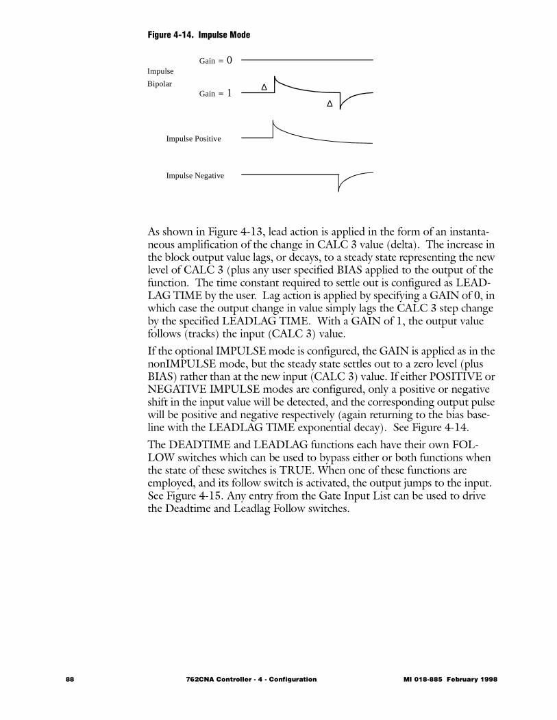
Figure 4-14. Impulse Mode
As shown in Figure 4-13, lead action is applied in the form of an instanta-neous amplification of the change in CALC 3 value (delta). The increase in the block output value lags, or decays, to a steady state representing the new level of CALC 3 (plus any user specified BIAS applied to the output of the function. The time constant required to settle out is configured as LEAD-LAG TIME by the user. Lag action is applied by specifying a GAIN of 0, in which case the output change in value simply lags the CALC 3 step change by the specified LEADLAG TIME. With a GAIN of 1, the output value follows (tracks) the input (CALC 3) value.If the optional IMPULSE mode is configured, the GAIN is applied as in the nonIMPULSE mode, but the steady state settles out to a zero level (plus BIAS) rather than at the new input (CALC 3) value. If either POSITIVE or NEGATIVE IMPULSE modes are configured, only a positive or negative shift in the input value will be detected, and the corresponding output pulse will be positive and negative respectively (again returning to the bias base-line with the LEADLAG TIME exponential decay). See Figure 4-14.The DEADTIME and LEADLAG functions each have their own FOL-LOW switches which can be used to bypass either or both functions when the state of these switches is TRUE. When one of these functions are employed, and its follow switch is activated, the output jumps to the input. See Figure 4-15. Any entry from the Gate Input List can be used to drive the Deadtime and Leadlag Follow switches.
Gain = 0
Gain = 1
Impulse Positive
Impulse
Bipolar
Impulse Negative
∆
∆
88 762CNA Controller - 4 - Configuration MI 018-885 February 1998
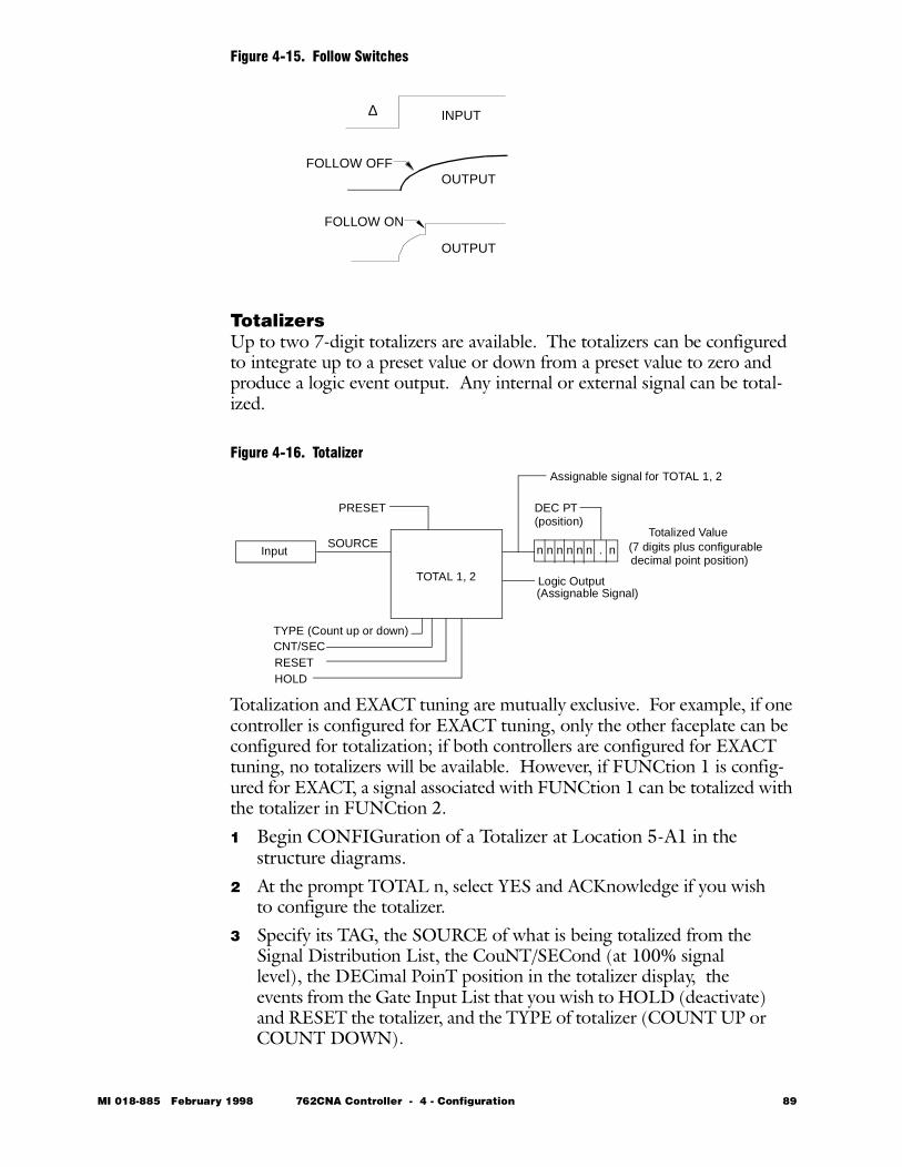
Figure 4-15. Follow Switches
TotalizersUp to two 7-digit totalizers are available. The totalizers can be configured to integrate up to a preset value or down from a preset value to zero and produce a logic event output. Any internal or external signal can be total-ized.
Figure 4-16. Totalizer
Totalization and EXACT tuning are mutually exclusive. For example, if one controller is configured for EXACT tuning, only the other faceplate can be configured for totalization; if both controllers are configured for EXACT tuning, no totalizers will be available. However, if FUNCtion 1 is config-ured for EXACT, a signal associated with FUNCtion 1 can be totalized with the totalizer in FUNCtion 2.
1 Begin CONFIGuration of a Totalizer at Location 5-A1 in the structure diagrams.
2 At the prompt TOTAL n, select YES and ACKnowledge if you wish to configure the totalizer.
3 Specify its TAG, the SOURCE of what is being totalized from the Signal Distribution List, the CouNT/SECond (at 100% signal level), the DECimal PoinT position in the totalizer display, the events from the Gate Input List that you wish to HOLD (deactivate) and RESET the totalizer, and the TYPE of totalizer (COUNT UP or COUNT DOWN).
∆
FOLLOW OFF
FOLLOW ON
INPUT
OUTPUT
OUTPUT
Input
TOTAL 1, 2
n n n n n n . nSOURCETotalized Value
PRESET
HOLDRESETCNT/SECTYPE (Count up or down)
Logic Output(Assignable Signal)
(7 digits plus configurabledecimal point position)
DEC PT(position)
Assignable signal for TOTAL 1, 2
MI 018-885 February 1998 762CNA Controller - 4 - Configuration 89
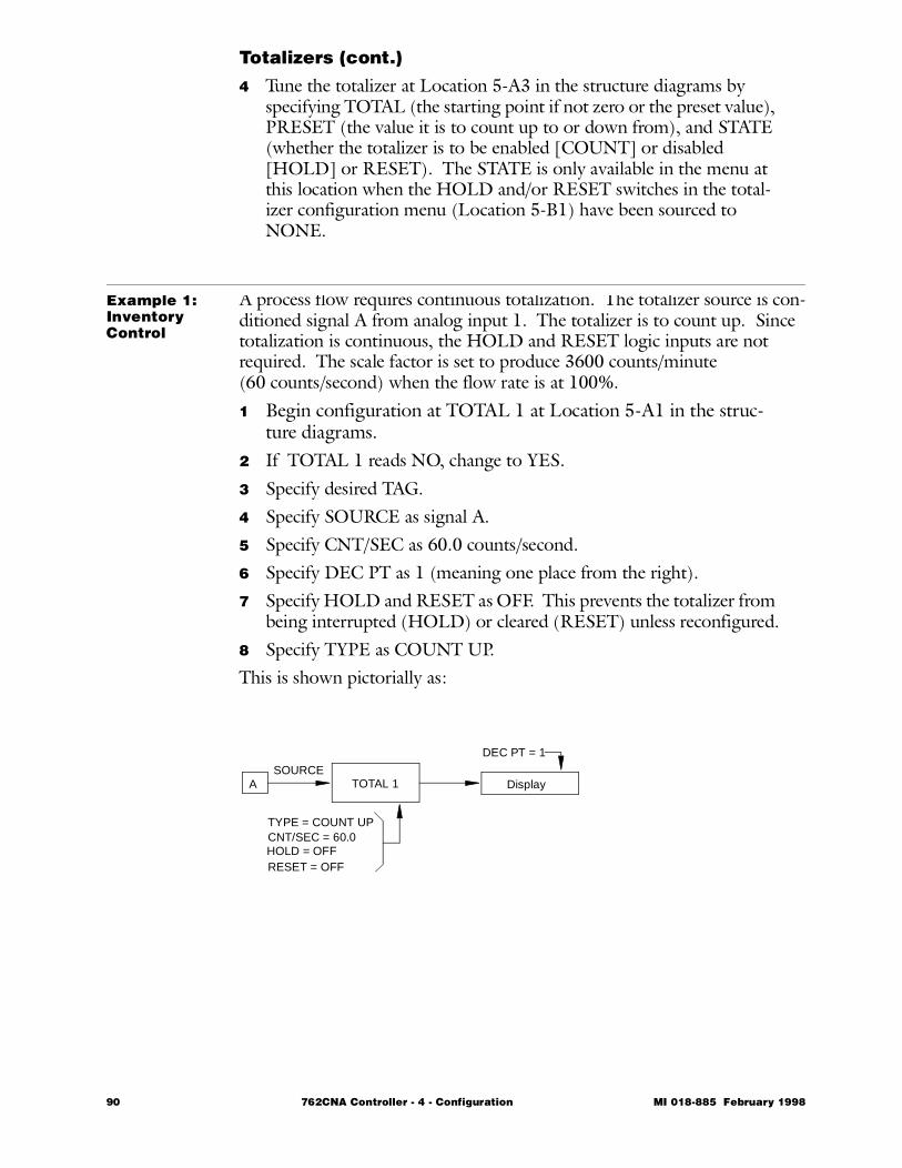
Totalizers (cont.)
4 Tune the totalizer at Location 5-A3 in the structure diagrams by specifying TOTAL (the starting point if not zero or the preset value), PRESET (the value it is to count up to or down from), and STATE (whether the totalizer is to be enabled [COUNT] or disabled [HOLD] or RESET). The STATE is only available in the menu at this location when the HOLD and/or RESET switches in the total-izer configuration menu (Location 5-B1) have been sourced to NONE.
Example 1: Inventory Control
A process flow requires continuous totalization. The totalizer source is con-ditioned signal A from analog input 1. The totalizer is to count up. Since totalization is continuous, the HOLD and RESET logic inputs are not required. The scale factor is set to produce 3600 counts/minute (60 counts/second) when the flow rate is at 100%.1 Begin configuration at TOTAL 1 at Location 5-A1 in the struc-
ture diagrams.2 If TOTAL 1 reads NO, change to YES.3 Specify desired TAG.4 Specify SOURCE as signal A.5 Specify CNT/SEC as 60.0 counts/second.6 Specify DEC PT as 1 (meaning one place from the right).7 Specify HOLD and RESET as OFF. This prevents the totalizer from
being interrupted (HOLD) or cleared (RESET) unless reconfigured.8 Specify TYPE as COUNT UP.This is shown pictorially as:
TOTAL 1A Display
HOLD = OFFRESET = OFF
SOURCE
TYPE = COUNT UPCNT/SEC = 60.0
DEC PT = 1
90 762CNA Controller - 4 - Configuration MI 018-885 February 1998
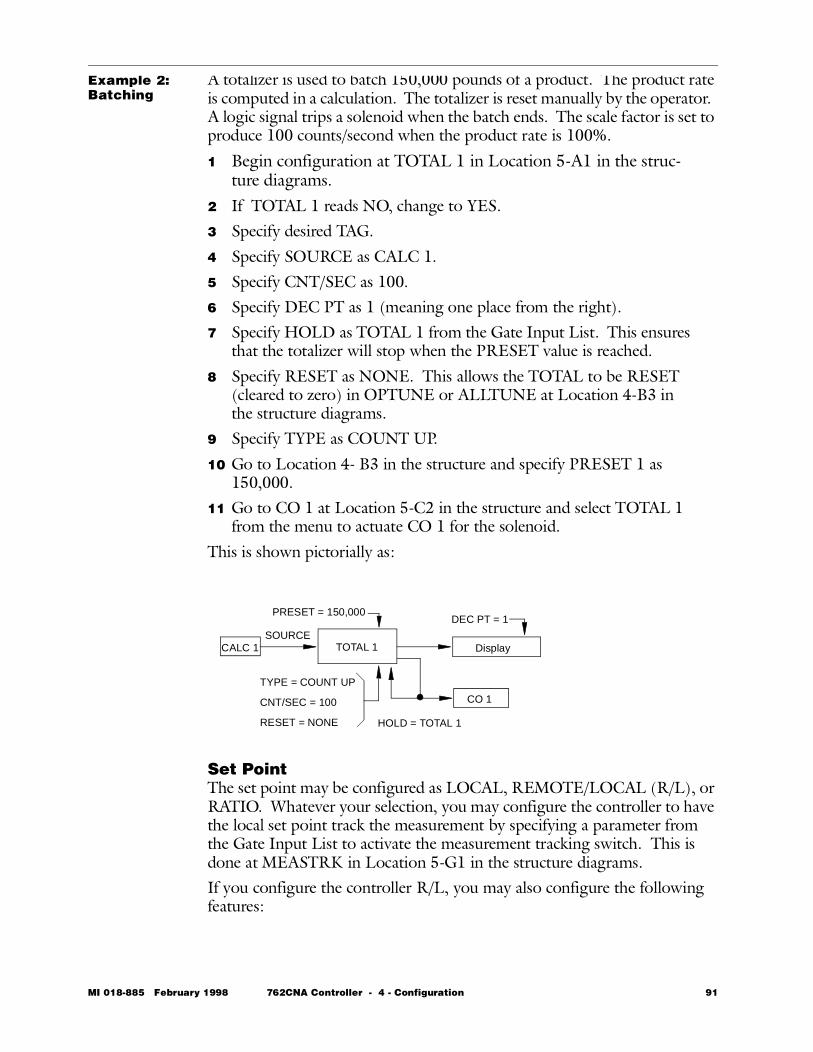
Example 2: Batching
A totalizer is used to batch 150,000 pounds of a product. The product rate is computed in a calculation. The totalizer is reset manually by the operator. A logic signal trips a solenoid when the batch ends. The scale factor is set to produce 100 counts/second when the product rate is 100%.
1 Begin configuration at TOTAL 1 in Location 5-A1 in the struc-ture diagrams.
2 If TOTAL 1 reads NO, change to YES.3 Specify desired TAG.4 Specify SOURCE as CALC 1.5 Specify CNT/SEC as 100.6 Specify DEC PT as 1 (meaning one place from the right).7 Specify HOLD as TOTAL 1 from the Gate Input List. This ensures
that the totalizer will stop when the PRESET value is reached.8 Specify RESET as NONE. This allows the TOTAL to be RESET
(cleared to zero) in OPTUNE or ALLTUNE at Location 4-B3 in the structure diagrams.
9 Specify TYPE as COUNT UP.10 Go to Location 4- B3 in the structure and specify PRESET 1 as
150,000.11 Go to CO 1 at Location 5-C2 in the structure and select TOTAL 1
from the menu to actuate CO 1 for the solenoid.This is shown pictorially as:
Set PointThe set point may be configured as LOCAL, REMOTE/LOCAL (R/L), or RATIO. Whatever your selection, you may configure the controller to have the local set point track the measurement by specifying a parameter from the Gate Input List to activate the measurement tracking switch. This is done at MEASTRK in Location 5-G1 in the structure diagrams.If you configure the controller R/L, you may also configure the following features:
TOTAL 1 Display
HOLD = TOTAL 1RESET = NONE
SOURCE
TYPE = COUNT UP
CNT/SEC = 100
DEC PT = 1
CALC 1
PRESET = 150,000
CO 1
MI 018-885 February 1998 762CNA Controller - 4 - Configuration 91
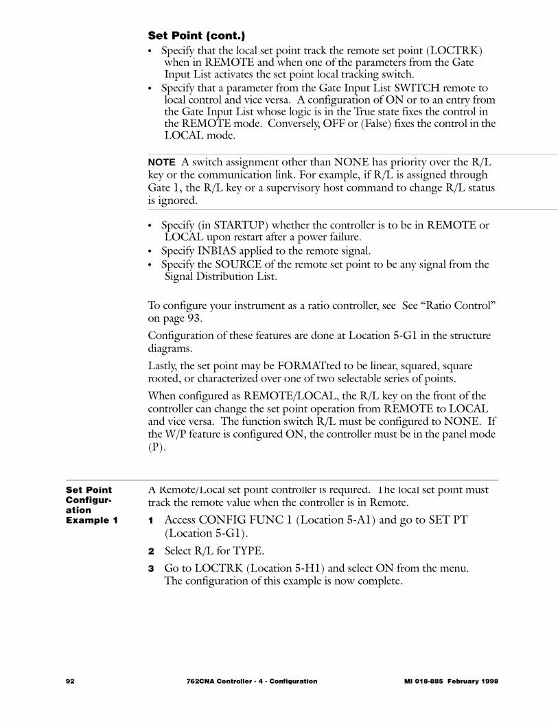
Set Point (cont.)• Specify that the local set point track the remote set point (LOCTRK)
when in REMOTE and when one of the parameters from the Gate Input List activates the set point local tracking switch.
• Specify that a parameter from the Gate Input List SWITCH remote to local control and vice versa. A configuration of ON or to an entry from the Gate Input List whose logic is in the True state fixes the control in the REMOTE mode. Conversely, OFF or (False) fixes the control in the LOCAL mode.
NOTE A switch assignment other than NONE has priority over the R/L key or the communication link. For example, if R/L is assigned through Gate 1, the R/L key or a supervisory host command to change R/L status is ignored.
• Specify (in STARTUP) whether the controller is to be in REMOTE or LOCAL upon restart after a power failure.
• Specify INBIAS applied to the remote signal.• Specify the SOURCE of the remote set point to be any signal from the
Signal Distribution List.
To configure your instrument as a ratio controller, see See “Ratio Control” on page 93.Configuration of these features are done at Location 5-G1 in the structure diagrams.Lastly, the set point may be FORMATted to be linear, squared, square rooted, or characterized over one of two selectable series of points.When configured as REMOTE/LOCAL, the R/L key on the front of the controller can change the set point operation from REMOTE to LOCAL and vice versa. The function switch R/L must be configured to NONE. If the W/P feature is configured ON, the controller must be in the panel mode (P).
Set Point Configur-ation Example 1
A Remote/Local set point controller is required. The local set point must track the remote value when the controller is in Remote.1 Access CONFIG FUNC 1 (Location 5-A1) and go to SET PT
(Location 5-G1).2 Select R/L for TYPE.3 Go to LOCTRK (Location 5-H1) and select ON from the menu.
The configuration of this example is now complete.
92 762CNA Controller - 4 - Configuration MI 018-885 February 1998
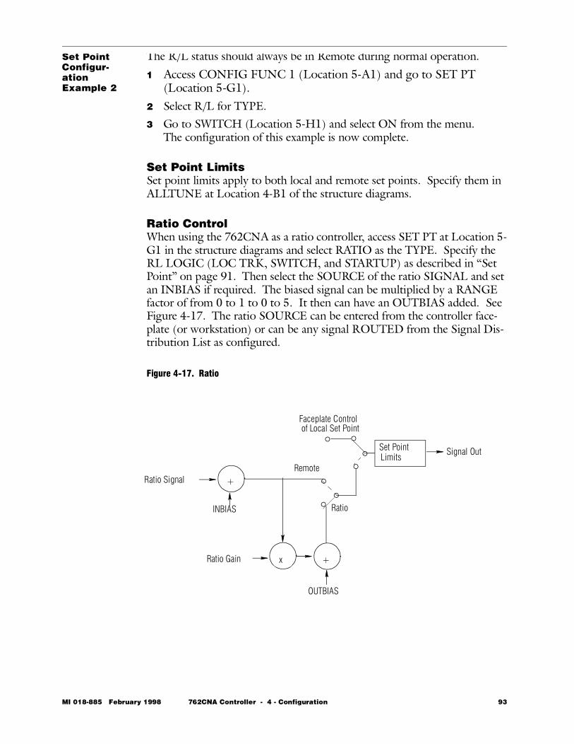
Set Point Configur-ation Example 2
The R/L status should always be in Remote during normal operation.
1 Access CONFIG FUNC 1 (Location 5-A1) and go to SET PT (Location 5-G1).
2 Select R/L for TYPE.3 Go to SWITCH (Location 5-H1) and select ON from the menu.
The configuration of this example is now complete.
Set Point LimitsSet point limits apply to both local and remote set points. Specify them in ALLTUNE at Location 4-B1 of the structure diagrams.
Ratio ControlWhen using the 762CNA as a ratio controller, access SET PT at Location 5-G1 in the structure diagrams and select RATIO as the TYPE. Specify the RL LOGIC (LOC TRK, SWITCH, and STARTUP) as described in “Set Point” on page 91. Then select the SOURCE of the ratio SIGNAL and set an INBIAS if required. The biased signal can be multiplied by a RANGE factor of from 0 to 1 to 0 to 5. It then can have an OUTBIAS added. See Figure 4-17. The ratio SOURCE can be entered from the controller face-plate (or workstation) or can be any signal ROUTED from the Signal Dis-tribution List as configured.
Figure 4-17. Ratio
Set PointLimits
INBIAS
OUTBIAS
Ratio Gain
Faceplate Controlof Local Set Point
Ratio Signal
Signal Out
+
+x
Remote
Ratio
MI 018-885 February 1998 762CNA Controller - 4 - Configuration 93
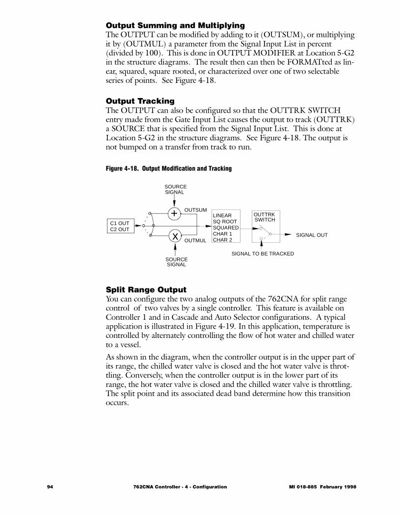
Output Summing and MultiplyingThe OUTPUT can be modified by adding to it (OUTSUM), or multiplying it by (OUTMUL) a parameter from the Signal Input List in percent (divided by 100). This is done in OUTPUT MODIFIER at Location 5-G2 in the structure diagrams. The result then can then be FORMATted as lin-ear, squared, square rooted, or characterized over one of two selectable series of points. See Figure 4-18.
Output TrackingThe OUTPUT can also be configured so that the OUTTRK SWITCH entry made from the Gate Input List causes the output to track (OUTTRK) a SOURCE that is specified from the Signal Input List. This is done at Location 5-G2 in the structure diagrams. See Figure 4-18. The output is not bumped on a transfer from track to run.
Figure 4-18. Output Modification and Tracking
Split Range OutputYou can configure the two analog outputs of the 762CNA for split range control of two valves by a single controller. This feature is available on Controller 1 and in Cascade and Auto Selector configurations. A typical application is illustrated in Figure 4-19. In this application, temperature is controlled by alternately controlling the flow of hot water and chilled water to a vessel. As shown in the diagram, when the controller output is in the upper part of its range, the chilled water valve is closed and the hot water valve is throt-tling. Conversely, when the controller output is in the lower part of its range, the hot water valve is closed and the chilled water valve is throttling. The split point and its associated dead band determine how this transition occurs.
LINEARSQ ROOTSQUAREDCHAR 1CHAR 2
OUTTRK SWITCH
SIGNAL TO BE TRACKED
SIGNAL OUT
+
xC1 OUTC2 OUT
SOURCESIGNAL
SOURCESIGNAL
OUTSUM
OUTMUL
94 762CNA Controller - 4 - Configuration MI 018-885 February 1998
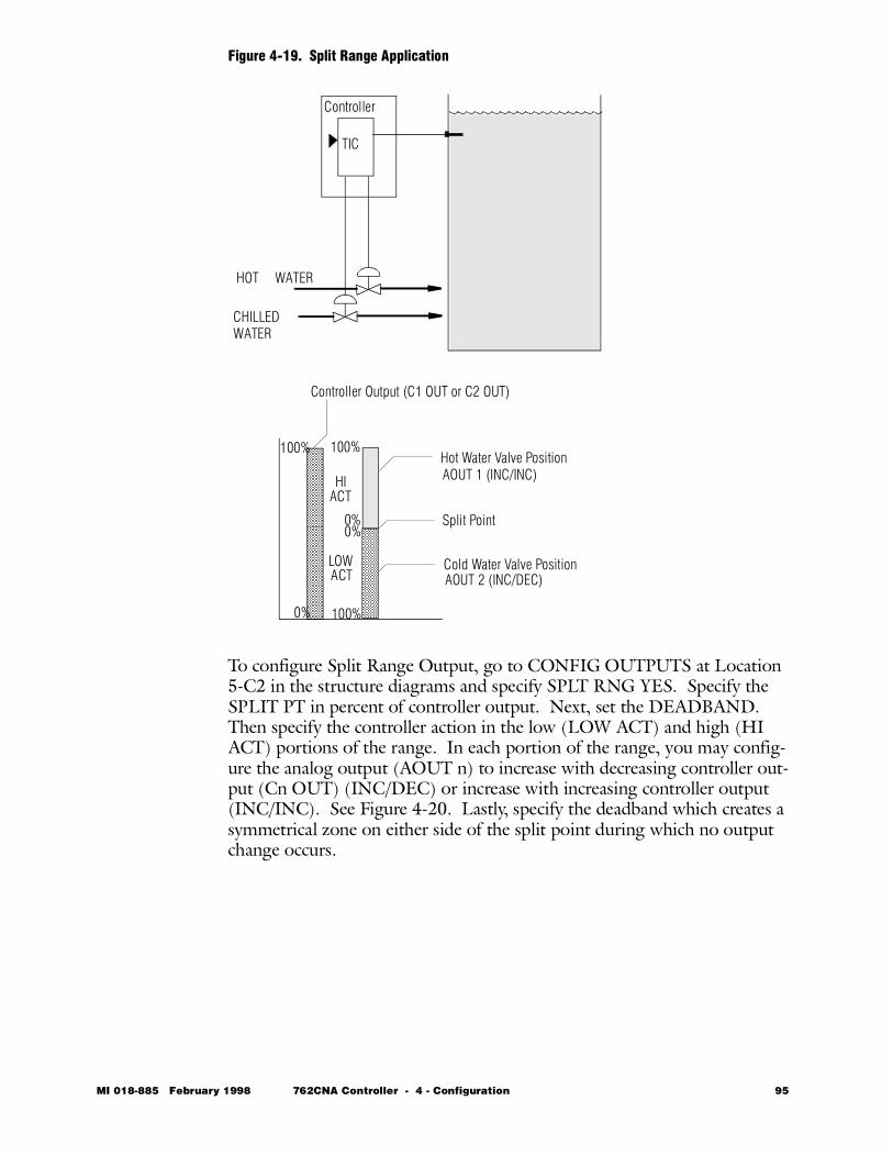
Figure 4-19. Split Range Application
To configure Split Range Output, go to CONFIG OUTPUTS at Location 5-C2 in the structure diagrams and specify SPLT RNG YES. Specify the SPLIT PT in percent of controller output. Next, set the DEADBAND. Then specify the controller action in the low (LOW ACT) and high (HI ACT) portions of the range. In each portion of the range, you may config-ure the analog output (AOUT n) to increase with decreasing controller out-put (Cn OUT) (INC/DEC) or increase with increasing controller output (INC/INC). See Figure 4-20. Lastly, specify the deadband which creates a symmetrical zone on either side of the split point during which no output change occurs.
TIC
Controller
CHILLEDWATER
HOT WATER
Controller Output (C1 OUT or C2 OUT)
Hot Water Valve Position
Cold Water Valve Position
0%
100% 100%
0%0%
100%
Split Point
AOUT 2 (INC/DEC)
AOUT 1 (INC/INC)HI
LOWACT
ACT
MI 018-885 February 1998 762CNA Controller - 4 - Configuration 95
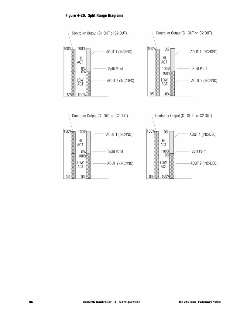
Figure 4-20. Split Range Diagrams
Controller Output (C1 OUT or C2 OUT)
0%
100% 100%
0%0%
100%
Split Point
AOUT 2 (INC/DEC)
AOUT 1 (INC/INC)
HI
LOWACT
ACT
Controller Output (C1 OUT or C2 OUT)
0%
100% 0%
100%100%
0%
Split Point
AOUT 2 (INC/INC)
AOUT 1 (INC/DEC)
HI
LOWACT
ACT
Controller Output (C1 OUT or C2 OUT)
0%
100% 100%
0%100%
0%
Split Point
AOUT 2 (INC/INC)
AOUT 1 (INC/INC)
HI
LOWACT
ACT
Controller Output (C1 OUT or C2 OUT)
0%
100% 0%
100%
100%
0%Split Point
AOUT 2 (INC/DEC)
AOUT 1 (INC/DEC)
HI
LOWACT
ACT
96 762CNA Controller - 4 - Configuration MI 018-885 February 1998
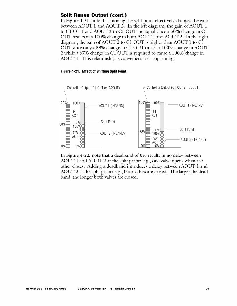
Split Range Output (cont.)In Figure 4-21, note that moving the split point effectively changes the gain between AOUT 1 and AOUT 2. In the left diagram, the gain of AOUT 1 to C1 OUT and AOUT 2 to C1 OUT are equal since a 50% change in C1 OUT results in a 100% change in both AOUT 1 and AOUT 2. In the right diagram, the gain of AOUT 2 to C1 OUT is higher than AOUT 1 to C1 OUT since only a 33% change in C1 OUT causes a 100% change in AOUT 2 while a 67% change in C1 OUT is required to cause a 100% change in AOUT 1. This relationship is convenient for loop tuning.
Figure 4-21. Effect of Shifting Split Point
In Figure 4-22, note that a deadband of 0% results in no delay between AOUT 1 and AOUT 2 at the split point; e.g., one valve opens when the other closes. Adding a deadband introduces a delay between AOUT 1 and AOUT 2 at the split point; e.g., both valves are closed. The larger the dead-band, the longer both valves are closed.
Controller Output (C1 OUT or C2OUT)
0%
100% 100%
0%100%
0%
Split Point
AOUT 2 (INC/INC)
AOUT 1 (INC/INC)
HI
LOWACT
ACT
Controller Output (C1 OUT or C2OUT)
0%
100% 100%
0%100%
0%
Split Point
AOUT 2 (INC/INC)
AOUT 1 (INC/INC)
HI
LOWACT
ACT
50%
33%
MI 018-885 February 1998 762CNA Controller - 4 - Configuration 97
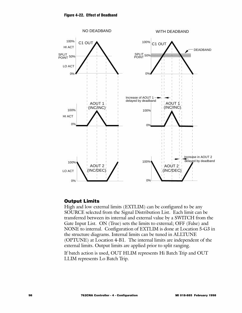
Figure 4-22. Effect of Deadband
Output LimitsHigh and low external limits (EXTLIM) can be configured to be any SOURCE selected from the Signal Distribution List. Each limit can be transferred between its internal and external value by a SWITCH from the Gate Input List. ON (True) sets the limits to external; OFF (False) and NONE to internal. Configuration of EXTLIM is done at Location 5-G3 in the structure diagrams. Internal limits can be tuned in ALLTUNE (OPTUNE) at Location 4-B1. The internal limits are independent of the external limits. Output limits are applied prior to split ranging.If batch action is used, OUT HLIM represents Hi Batch Trip and OUT LLIM represents Lo Batch Trip.
SPLIT
HI ACT
LO ACT
NO DEADBAND
C1 OUT
AOUT 1
AOUT 2
POINTSPLITPOINT
AOUT 1
AOUT 2
C1 OUT
WITH DEADBAND
HI ACT
LO ACT
(INC/INC)
(INC/DEC)
(INC/INC)
(INC/DEC)
100%
0%
100%
0%
100%
0%
100%
0%
100%
0%
100%
0%
50%50%
DEADBAND
Increase in AOUT 2delayed by deadband
Increase of AOUT 1delayed by deadband
98 762CNA Controller - 4 - Configuration MI 018-885 February 1998
Output ActionYou may configure the controller algorithm output (C1 OUT or C2 OUT) to increase with decreasing measurement (INC/DEC) or increasing mea-surement (INC/INC). This is done at ACTION in Location 5-G2 in the structure diagrams.
Output Upon Restart (STARTUP)The value of output upon restart (STARTUP) after a power loss can be con-figured to any value from 0% to 100% or the last value before the power loss occurred. This is done at OUTPUT STARTUP in Location 5-G3 in the structure diagrams.
Output ReverseThe output bargraph on the controller display is normally a direct indication of the output signal and the manipulated variable. Increasing the controller output raises the bargraph (and the corresponding digitally displayed value), increases the manipulated variable and usually, but not always, increases the process or measured variable.In some applications, a valve operator or positioner is selected for fail-safe or other reasons, where an increase in controller output actually decreases the manipulated variable. If not addressed, this can result in confusion when viewing the display, as well as improper implementation of high-low alarms and high-low limits.This can be easily compensated for, by first completely configuring the con-troller just as if the manipulated variable changed directly with the output, and then, as the last step, simply selecting YES for REVERSE in the OUT-PUTS, AOUT1/AOUT2 menu (Location 5-D2 in the structure diagrams). When configured in this manner, the output bagraph will rise and the manipulated variable will increase when the analog output decreases, thus providing the proper response with a reverse acting valve operator.
Output BargraphThe Output Bargraph causes any item from the Signal Distribution List (Location 6) to be displayed on the output (right) bargraph. This allows you to indicate a true (live) output. For example, the output from a valve position transmitter could be connected to an unused input which then could be displayed on the output bargraph. This feature is configured at OUTBAR in Location 5-E2 in the structure diagrams.
MI 018-885 February 1998 762CNA Controller - 4 - Configuration 99
CharacterizersCharacterization consists of one or two curves of 8 segments (9 points). Each curve may be assigned to any of the following signals:• Analog Input A, B, C, or D (Location 5-B2)• Frequency Input E or F (Location 5-B2)• Measurement of a Controller, MEAS (Location 5-G2)• Set point of a Controller, SET PT (Location 5-G1)• Nonlinear Controller, NONLIN (Location 5-G2)• Output of a Controller, OUTPUT (Location 5-G2)• Calculation, CALC (Location 5-C1)
NOTE Vertical slope of a curve is not allowed (for any one value of X there can be only one value of Y).
Entries may be expressed in whole numbers or to tenths of a whole number. The specification of the sequence of X, Y pairs is done at Location 5-D1.
Nonlinear ControlThe controller error (difference between measurement and set point) may be characterized over one of two selectable series of points at Location 5-G2 in the structure diagrams. This type of control is often used for difficult pH applications when the set point is not changed and when set as a deadzone for nonlinear filtering of error noise. See section immediately above for more information on Characterization.
pH DisplayThe display of the measurement, local set point, or remote set point may be displayed before or after the signal is characterized. If pH DISP is activated (ON) the displays are before characterization. This feature is often used on a pH application when it is important for the operator to read pH, but con-trol be performed on concentration. Specify this feature at Location5-E2 in the structure diagrams.
100 762CNA Controller - 4 - Configuration MI 018-885 February 1998
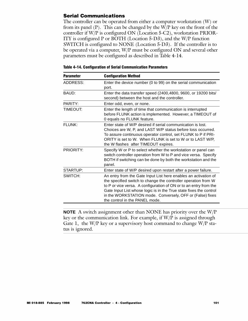
Serial CommunicationsThe controller can be operated from either a computer workstation (W) or from its panel (P). This can be changed by the W/P key on the front of the controller if W/P is configured ON (Location 5-C2), workstation PRIOR-ITY is configured P or BOTH (Location 5-D3), and the W/P function SWITCH is configured to NONE (Location 5-D3). If the controller is to be operated via a computer, W/P must be configured ON and several other parameters must be configured as described in Table 4-14.
NOTE A switch assignment other than NONE has priority over the W/P key or the communication link. For example, if W/P is assigned through Gate 1, the W/P key or a supervisory host command to change W/P sta-tus is ignored.
Table 4-14. Configuration of Serial Communication Parameters
Parameter Configuration Method
ADDRESS: Enter the device number (0 to 99) on the serial communication port.
BAUD: Enter the data transfer speed (2400,4800, 9600, or 19200 bits/second) between the host and the controller.
PARITY: Enter odd, even, or none.TIMEOUT: Enter the length of time that communication is interrupted
before FLUNK action is implemented. However, a TIMEOUT of 0 equals no FLUNK feature.
FLUNK: Enter state of W/P desired if serial communication is lost. Choices are W, P, and LAST W/P status before loss occurred. To assure continuous operator control, set FLUNK to P if PRI-ORITY is set to W. When FLUNK is set to W or to LAST W/P, the W flashes after TIMEOUT expires.
PRIORITY: Specify W or P to select whether the workstation or panel can switch controller operation from W to P and vice versa. Specify BOTH if switching can be done by both the workstation and the panel.
STARTUP: Enter state of W/P desired upon restart after a power failure.SWITCH: An entry from the Gate Input List here enables an activation of
the specified switch to change the controller operation from W to P or vice versa. A configuration of ON or to an entry from the Gate Input List whose logic is in the True state fixes the control in the WORKSTATION mode. Conversely, OFF or (False) fixes the control in the PANEL mode.
MI 018-885 February 1998 762CNA Controller - 4 - Configuration 101
Communi-cations Example
Serial communications will be used to supervise the controller at 2400 baud and with address number 6. The controller should FLUNK to manual and panel after a TIMEOUT of 10 minutes; that is, when the host has had no communication with the controller for over 10 minutes.
1 Access CONFIG FUNC 1 and go to A/M (Location 5-G2).2 Go to FLUNK and select M from the menu.3 Access CONFIG W/P at Location 5-C2 and select ON.4 Enter 06 in the ADDRESS block.5 Select 2400 from the menu for BAUD.6 Select EVEN, ODD, or NONE for PARITY as desired.7 Go to TIMEOUT and confirm that the factory-configured value of
10.00 minutes is still in place. Change value if necessary.8 Select P from the menu for FLUNK. The configuration of this
example is now complete.
ToggleIf TOGGLE is configured ON, the user may go from one of the User Inter-face modes (READ or SET) to the Normal Operation mode and return to the function from which the User Interface was exited using the TAG key. TOGGLE functions above and below the PASSCODE barrier. However, this feature is particularly useful if the function is after the PASSCODE.TOGGLE only applies if the controller is in PANEL (P) mode. Also, TOG-GLE defaults to OFF in a power failure.Lastly, if TOGGLE is configured and the user is in the firmware structure below the PASSCODE but wants to go to a section of the structure above the PASSCODE, he must do the following:1 Press a long TAG (more than 0.3 second). Display will read EXIT
PASS NO.2 Using an arrow key, change the NO to YES. Press ACK key. Dis-
play will show Normal Operation.3 Pressing the TAG key again will bring you to READ in the firmware
structure and not to the function from which the user interface was previously exited.
NOTE If NO is ACKnowledged in Step 2, the display will show Normal Operation. However, the next use of the TAG key will return you to the function from which the User Interface was exited.
Figure 4-23 expresses the Toggle feature pictorially. The configuration parameter ALARM 3 ACTION was selected arbitrarily for the example in this figure.
102 762CNA Controller - 4 - Configuration MI 018-885 February 1998
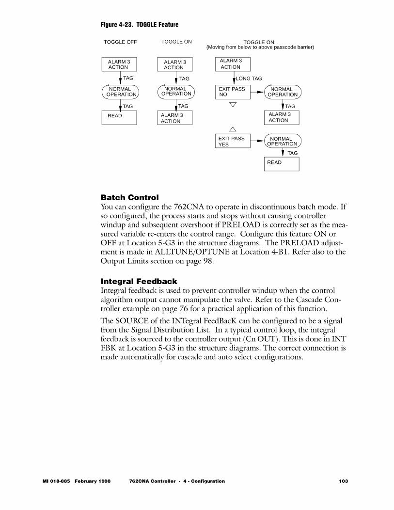
Figure 4-23. TOGGLE Feature
Batch ControlYou can configure the 762CNA to operate in discontinuous batch mode. If so configured, the process starts and stops without causing controller windup and subsequent overshoot if PRELOAD is correctly set as the mea-sured variable re-enters the control range. Configure this feature ON or OFF at Location 5-G3 in the structure diagrams. The PRELOAD adjust-ment is made in ALLTUNE/OPTUNE at Location 4-B1. Refer also to the Output Limits section on page 98.
Integral FeedbackIntegral feedback is used to prevent controller windup when the control algorithm output cannot manipulate the valve. Refer to the Cascade Con-troller example on page 76 for a practical application of this function.The SOURCE of the INTegral FeedBacK can be configured to be a signal from the Signal Distribution List. In a typical control loop, the integral feedback is sourced to the controller output (Cn OUT). This is done in INT FBK at Location 5-G3 in the structure diagrams. The correct connection is made automatically for cascade and auto select configurations.
ALARM 3ACTION
ALARM 3ACTION
NORMALOPERATION
TAG
TAG
TAG
TAG
NORMALOPERATION
READ ALARM 3ACTION
ALARM 3ACTION
EXIT PASSNO
EXIT PASSYES
NORMALOPERATION
NORMALOPERATION
READ
ALARM 3ACTION
LONG TAG
TAG
TAG
TOGGLE ONTOGGLE OFF TOGGLE ON(Moving from below to above passcode barrier)
MI 018-885 February 1998 762CNA Controller - 4 - Configuration 103
Rate of Change AlarmsA Rate of Change alarm is used when the change of a variable in an incre-ment of time is important; i.e., the change in temperature per change in unit time in a reactor. A Rate of Change alarm has one input variable. The alarm levels are entered in percent and referenced to time. The units are per-cent per minute. When the attached monitored variable exceeds the alarm level, an alarm condition occurs and the Boolean output associated with that alarm is set to True. The time interval for trip points is fixed at one minute; e.g., a level of 50% equals 50%/minute. The time between the alarm condi-tion and activation of the alarm is typically 5 to 10 seconds. It takes less time if the rate is way over the limit but longer if the rate is only slightly over the limit.The input variable is assigned from the Signal Distribution List using the parameter ATTACH at Location 5-B2 in the structure diagrams.Alarm levels and deadband have a different meaning for ROC alarms. For an ROC alarm, alarm levels and deadband are interpreted as percent change per minute. This may be thought of as an absolute alarm applied to dm/dt instead of to m, where dm/dt is the rate of change in percent per minute. The filter time is 6 seconds and dm/dt values are approximately 1% precise. A minimum of 5%/minute deadband should be used on ROC alarms. Lastly, Rate of Change alarms can not be configured for display.
104 762CNA Controller - 4 - Configuration MI 018-885 February 1998
Configuration Copy AccessoryA configuration copy accessory (Part L0122TU) is available from Foxboro. With this accessory, additional controllers can be configured to match an existing one without the need to go through the step-by-step configuration procedure previously described.Even if an exact duplicate configuration is not desired, the configuration copy accessory can still be used. If the configuration of the second control-ler is to be similar to the first, the first one can be copied and the copy then changed using the step-by-step procedures described in this Chapter. The procedure used to copy a configuration is as follows:1 Depress latch under front panel to withdraw controller. With-
draw controller several inches from housing (power is removed from unit).
2 Release the locking latch on the socket of the memory module (NOVRAM) and lift the module out of its socket. Identify this module so that it cannot be confused with the module to be config-ured.
3 Insert configuration copy accessory (See Figure 4-24) into this socket with ribbon cable toward front of controller and lock latch of socket.
4 Release both latches on copy accessory. Position configured memory module so that the key is on bottom and insert module into left side of accessory (labeled “ORIG”). Lock left accessory latch.
5 Insert unconfigured memory module similarly into right side of accessory (labeled “COPY”). Lock right accessory latch.
6 Reconnect power by sliding controller back into housing with rib-bon cable extending out the front of the housing. When lower dis-play shows value of engineering units, new memory module is configured. This takes only a few seconds.
7 Withdraw controller from housing. Release all three latches and remove the two modules and copy accessory.
8 Plug original and newly configured memory modules back into their controllers. Lock latches. Reinstall controllers into their housings.
9 Calibrate controller with newly configured memory module. See Chapter 7 of this instruction.
MI 018-885 February 1998 762CNA Controller - 4 - Configuration 105
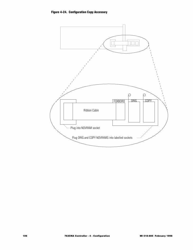
Figure 4-24. Configuration Copy Accessory
Ribbon Cable
FOXBORO ORIG COPY
Plug into NOVRAM socket
Plug ORIG and COPY NOVRAMS into labelled sockets
106 762CNA Controller - 4 - Configuration MI 018-885 February 1998
762C SINGLESTATION
MICROController
February 1998
Preface • xiii Chapter 1 Quick Check • 1 Chapter 2 Product Overview • 11 Chapter 3 Installation • 23 Chapter 4 Configuration • 49
Ð Chapter 5 Operation • 109 Chapter 6 EXACT Tuning • 135 Chapter 7 Calibration, Troubleshooting,
Maintenance • 159 Appendix A Specifications • 183 Appendix B Configuration Worksheets • 193 Appendix C Structure Diagrams • 237 Appendix D Parts List • 247 Appendix E Dimensional Print • 247 Appendix F Functional Diagram • 261 Glossary • 267 Index • 287
The Intelligent Automation People

108 762CNA Controller MI 018-885 February 1998
MI 018-885 Februar
5 Operation
The purpose of this section is to describe all features of the 762CNA Con-troller that are of interest to the process operator — how to read the dis-plays, how to operate the keys, and how to perform various operator functions.
The chapter is divided into the following major sections:• Functions • 110 • Controls and Indicators • 113 • Structure Diagrams • 113 • Modes of Operation • 116 • SET OPTUNE • 116 • NORMAL Mode of Operation • 117 • Operation as an Auto/Manual Station • 128 • Operation as a 3-variable Indicator Station • 129 • Operation as an Auto-Selector Station • 130 • Operation as a Cascade Control Station • 130 • Totalizer Operation • 131 • READ Mode Operation • 132
y 1998 762CNA Controller - 5 - Operation 109
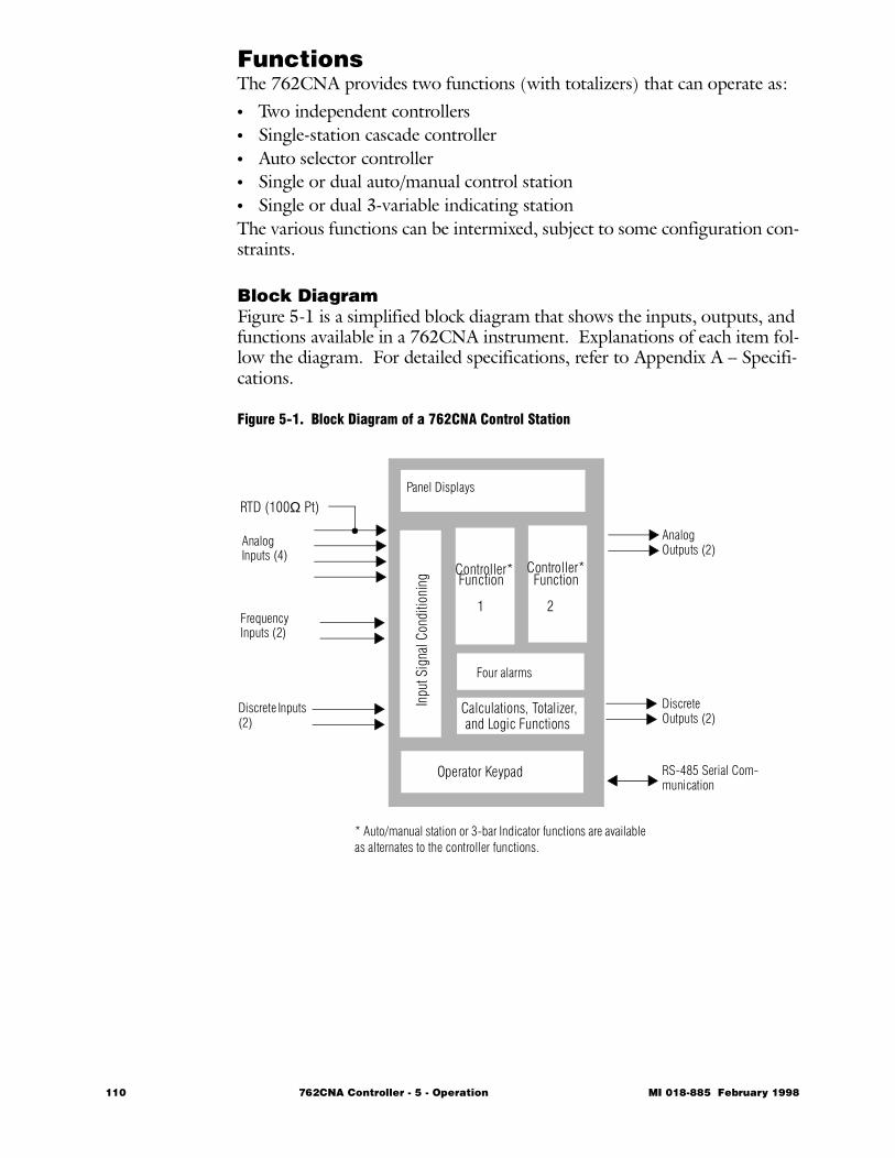
Functions The 762CNA provides two functions (with totalizers) that can operate as:• Two independent controllers• Single-station cascade controller• Auto selector controller• Single or dual auto/manual control station • Single or dual 3-variable indicating station The various functions can be intermixed, subject to some configuration con-straints.
Block DiagramFigure 5-1 is a simplified block diagram that shows the inputs, outputs, and functions available in a 762CNA instrument. Explanations of each item fol-low the diagram. For detailed specifications, refer to Appendix A – Specifi-cations.
Figure 5-1. Block Diagram of a 762CNA Control Station
1 2
Controller*
Panel Displays
Controller*
Inpu
t Sig
nal C
ondi
tioni
ng
Four alarms
Calculations, Totalizer,and Logic Functions
Operator Keypad
Analog Inputs (4)
Frequency Inputs (2)
Discrete Inputs (2)
Analog Outputs (2)
Discrete Outputs (2)
RS-485 Serial Com-munication
RTD (100Ω Pt)
* Auto/manual station or 3-bar Indicator functions are available as alternates to the controller functions.
Function Function
110 762CNA Controller - 5 - Operation MI 018-885 February 1998
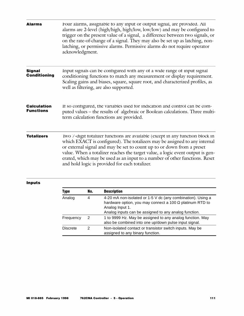
Alarms Four alarms, assignable to any input or output signal, are provided. All alarms are 2-level (high/high, high/low, low/low) and may be configured to trigger on the present value of a signal, a difference between two signals, or on the rate-of-change of a signal. They may also be set up as latching, non-latching, or permissive alarms. Permissive alarms do not require operator acknowledgment.
Signal Conditioning
Input signals can be configured with any of a wide range of input signal conditioning functions to match any measurement or display requirement. Scaling gains and biases, square, square root, and characterized profiles, as well as filtering, are also supported.
Calculation Functions
If so configured, the variables used for indication and control can be com-puted values – the results of algebraic or Boolean calculations. Three multi-term calculation functions are provided.
Totalizers Two 7-digit totalizer functions are available (except in any function block in which EXACT is configured). The totalizers may be assigned to any internal or external signal and may be set to count up to or down from a preset value. When a totalizer reaches the target value, a logic event output is gen-erated, which may be used as an input to a number of other functions. Reset and hold logic is provided for each totalizer.
Inputs
Type No. Description
Analog 4 4-20 mA non-isolated or 1-5 V dc (any combination). Using a hardware option, you may connect a 100 Ω platinum RTD to Analog Input 1.Analog inputs can be assigned to any analog function.
Frequency 2 1 to 9999 Hz. May be assigned to any analog function. May also be combined into one up/down pulse input signal.
Discrete 2 Non-isolated contact or transistor switch inputs. May be assigned to any binary function.
MI 018-885 February 1998 762CNA Controller - 5 - Operation 111
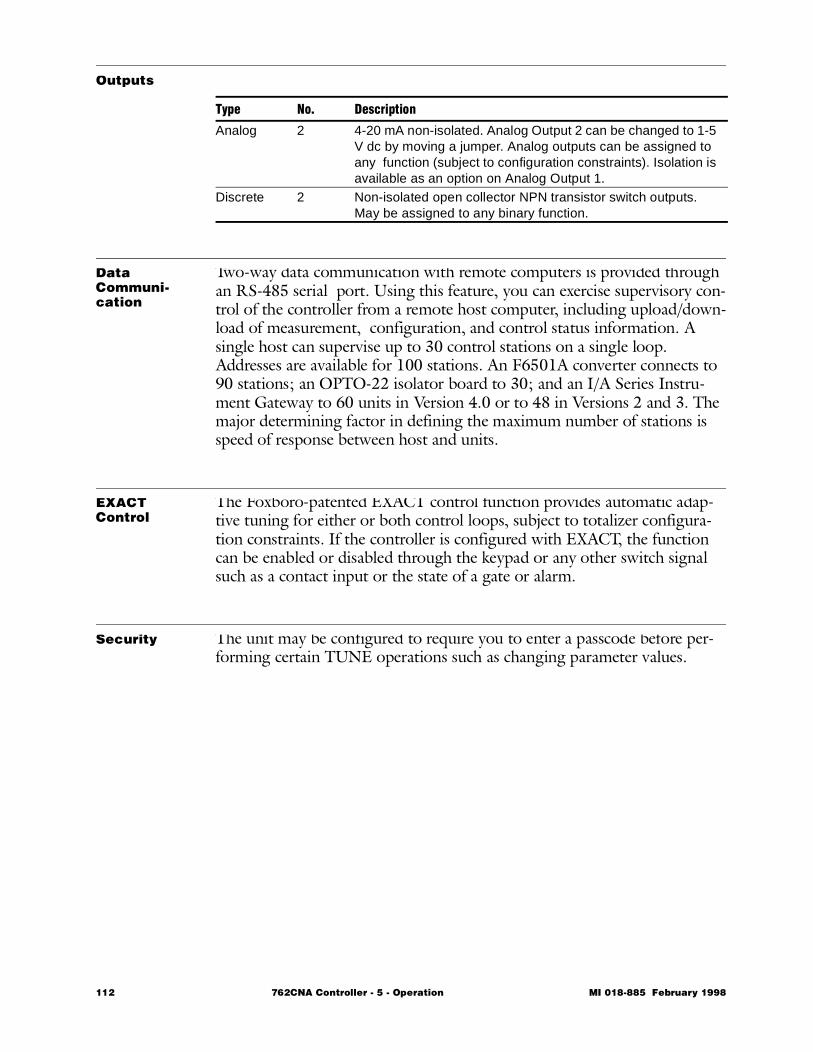
Outputs
Data Communi-cation
Two-way data communication with remote computers is provided through an RS-485 serial port. Using this feature, you can exercise supervisory con-trol of the controller from a remote host computer, including upload/down-load of measurement, configuration, and control status information. A single host can supervise up to 30 control stations on a single loop. Addresses are available for 100 stations. An F6501A converter connects to 90 stations; an OPTO-22 isolator board to 30; and an I/A Series Instru-ment Gateway to 60 units in Version 4.0 or to 48 in Versions 2 and 3. The major determining factor in defining the maximum number of stations is speed of response between host and units.
EXACT Control
The Foxboro-patented EXACT control function provides automatic adap-tive tuning for either or both control loops, subject to totalizer configura-tion constraints. If the controller is configured with EXACT, the function can be enabled or disabled through the keypad or any other switch signal such as a contact input or the state of a gate or alarm.
Security The unit may be configured to require you to enter a passcode before per-forming certain TUNE operations such as changing parameter values.
Type No. Description
Analog 2 4-20 mA non-isolated. Analog Output 2 can be changed to 1-5 V dc by moving a jumper. Analog outputs can be assigned to any function (subject to configuration constraints). Isolation is available as an option on Analog Output 1.
Discrete 2 Non-isolated open collector NPN transistor switch outputs. May be assigned to any binary function.
112 762CNA Controller - 5 - Operation MI 018-885 February 1998
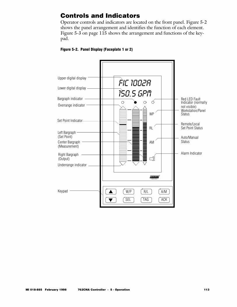
Controls and IndicatorsOperator controls and indicators are located on the front panel. Figure 5-2 shows the panel arrangement and identifies the function of each element. Figure 5-3 on page 115 shows the arrangement and functions of the key-pad.
Figure 5-2. Panel Display (Faceplate 1 or 2)
WP
RL
AM
FIC 1002A150.5 GPM
W/P R/L A/M
SEL TAG ACK
Overrange indicator
Upper digital display
Lower digital display
Bargraph indicator
Underrange indicator
Left Bargraph
Center Bargraph
Right Bargraph
Workstation/Panel
Remote/Local
Auto/Manual
Alarm Indicator
Set Point Status
Status
Red LED FaultIndicator (normally
Keypad
Status(Set Point)
(Measurement)
(Output)
not visible)
Set Point Indicator
MI 018-885 February 1998 762CNA Controller - 5 - Operation 113
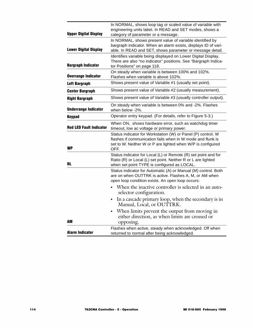
Upper Digital Display
In NORMAL, shows loop tag or scaled value of variable with engineering units label. In READ and SET modes, shows a category of parameter or a message.
Lower Digital Display
In NORMAL, shows present value of variable identified by bargraph indicator. When an alarm exists, displays ID of vari-able. In READ and SET, shows parameter or message detail.
Bargraph Indicator
Identifies variable being displayed on Lower Digital Display. There are also “no indicator” positions. See “Bargraph Indica-tor Positions” on page 118.
Overrange IndicatorOn steady when variable is between 100% and 102%. Flashes when variable is above 102%.
Left Bargraph Shows present value of Variable #1 (usually set point).
Center Bargraph Shows present value of Variable #2 (usually measurement).
Right Bargraph Shows present value of Variable #3 (usually controller output).
Underrange IndicatorOn steady when variable is between 0% and -2%. Flashes when below -2%.
Keypad Operator entry keypad. (For details, refer to Figure 5-3.)
Red LED Fault IndicatorWhen ON, shows hardware error, such as watchdog timer timeout, low ac voltage or primary power.
WP
Status indicator for Workstation (W) or Panel (P) control. W flashes if communication fails when in W mode and flunk is set to W. Neither W or P are lighted when W/P is configured OFF.
RL
Status indicator for Local (L) or Remote (R) set point and for Ratio (R) or Local (L) set point. Neither R or L are lighted when set point TYPE is configured as LOCAL.
AM
Status indicator for Automatic (A) or Manual (M) control. Both are on when OUTTRK is active. Flashes A, M, or AM when open loop condition exists. An open loop occurs:
• When the inactive controller is selected in an auto-selector configuration.
• In a cascade primary loop, when the secondary is in Manual, Local, or OUTTRK.
• When limits prevent the output from moving in either direction, as when limits are crossed or opposing.
Alarm Indicator Flashes when active, steady when acknowledged. Off when returned to normal after being acknowledged.
114 762CNA Controller - 5 - Operation MI 018-885 February 1998
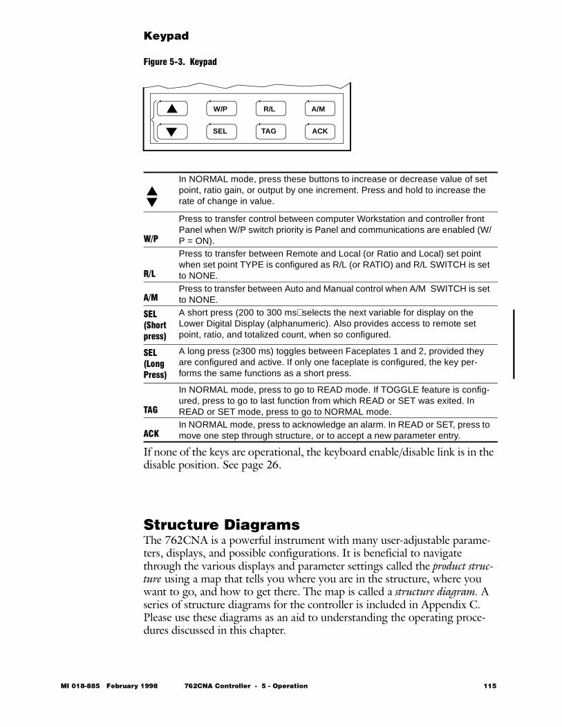
Keypad
Figure 5-3. Keypad
If none of the keys are operational, the keyboard enable/disable link is in the disable position. See page 26.
Structure DiagramsThe 762CNA is a powerful instrument with many user-adjustable parame-ters, displays, and possible configurations. It is beneficial to navigate through the various displays and parameter settings called the product struc-ture using a map that tells you where you are in the structure, where you want to go, and how to get there. The map is called a structure diagram. A series of structure diagrams for the controller is included in Appendix C. Please use these diagrams as an aid to understanding the operating proce-dures discussed in this chapter.
In NORMAL mode, press these buttons to increase or decrease value of set point, ratio gain, or output by one increment. Press and hold to increase the rate of change in value.
W/P
Press to transfer control between computer Workstation and controller front Panel when W/P switch priority is Panel and communications are enabled (W/P = ON).
R/L
Press to transfer between Remote and Local (or Ratio and Local) set point when set point TYPE is configured as R/L (or RATIO) and R/L SWITCH is set to NONE.
A/MPress to transfer between Auto and Manual control when A/M SWITCH is set to NONE.
SEL(Short press)
A short press (200 to 300 ms) selects the next variable for display on the Lower Digital Display (alphanumeric). Also provides access to remote set point, ratio, and totalized count, when so configured.
SEL(Long Press)
A long press (≥300 ms) toggles between Faceplates 1 and 2, provided they are configured and active. If only one faceplate is configured, the key per-forms the same functions as a short press.
TAG
In NORMAL mode, press to go to READ mode. If TOGGLE feature is config-ured, press to go to last function from which READ or SET was exited. In READ or SET mode, press to go to NORMAL mode.
ACKIn NORMAL mode, press to acknowledge an alarm. In READ or SET, press to move one step through structure, or to accept a new parameter entry.
W/P R/L A/M
SEL TAG ACK
MI 018-885 February 1998 762CNA Controller - 5 - Operation 115
Modes of OperationThe 762CNA operates in one of three modes:
This section of the manual describes NORMAL and READ modes of oper-ation. Refer to Section 4 – Configuration for detailed information on oper-ating in the SET mode.
SET OPTUNEThe operator can set parameters in ALLTUNE by first entering a passcode. He may also be permitted to adjust certain parameters in OPTUNE with-out entering a passcode. The parameter groups he can adjust are determined by the configuration of SHOWOP, which is described in Chapter 4 – Con-figuration. The various parameter groups that can be selected by SHOWOP are:• TUNE C1• C1 LIMIT• TUNE C2• C2 LIMIT• CONSTS• ALARMS• TOTALS• RD CFGThe steps necessary to perform the permitted SET OPTUNE functions can be determined by referring to Structure Diagram 4 on page 241.
Mode Description
NORMAL
In this mode, you can perform the usual configured functions such as reading values of variables, changing set points or output values, switching between auto and manual or remote and local, acknowledg-ing alarms, transferring between faceplates, etc.
READIn this mode, you can read the value and status of parameters, vari-ables, and if permitted, the current configuration.
SET
In this mode, you can change values of parameters that have been configured as operator-adjustable and, when past the passcode, val-ues of non-operator-adjustable parameters and the configuration.
116 762CNA Controller - 5 - Operation MI 018-885 February 1998

NORMAL Mode OperationWhen operating in NORMAL mode, you can:• Read values of the three variables displayed on the bargraphs and, if the
unit is so configured, read the values of remote and local set points and the present values of totalizers.
• Change control status (transfer between Workstation/Panel, Remote/Local, Ratio/Local, and Auto/Manual).
• Change set point or ratio in Auto and Manual, or change output in Manual, if the unit is configured to permit such changes.
• Display/acknowledge alarms.• Enable/disable EXACT tuning, subject to configuration constraints. • Switch from one faceplate display to the other.• Switch from NORMAL mode to READ and SET modes and return.• Initiate, hold, or reset totalizers, if so configured.
Entering a PasscodeThe unit will prompt you to enter an alphanumeric passcode before permit-ting you to perform certain restricted functions. The factory default is (blank)(blank)(blank), which can be entered by pressing ACK three times. (Refer to the structure diagrams in Appendix C for assistance in understand-ing the procedure described below.)To enter a passcode (starting in NORMAL mode):1 Press TAG. This places you in READ mode.2 Press ∆ to go to SET.3 Press ACK to go to OPTUNE.4 Press ∆ to go to SECURE.5 Press ACK to go to PASSCODE =. (With cursor under first digit
location, the digit flashes.)6 Press ∆ repeatedly (or press/hold) until first digit of your passcode is
displayed.7 Press ACK to accept first digit and move to next digit.8 Press ∆ repeatedly (or press/hold) until second digit of your passcode
is displayed.9 Press ACK to accept second digit and move to next digit.10 Repeat entry steps for next digit. When all digits have been entered correctly, the display shows ALLTUNE. You may now proceed with your SET operation.If the passcode is not accepted, the display shows the message, WRONG PASSCODE. Press TAG to return to normal operation and start over.
MI 018-885 February 1998 762CNA Controller - 5 - Operation 117

Reading Values of VariablesThe three bargraphs display the current values of the 3 variables – usually assigned to set point, measurement, and output. The bargraphs indicate 0 to 100% of full scale, with each display segment equal to 2% of full scale.To display the numerical value and measurement units of any one of the three variables on the lower line of the digital display, press the SEL key as many times as necessary to advance the bargraph indicator to the desired variable.
Bargraph Indicator Positions
You can identify which variable is being displayed by observing the position of the bargraph indicator. If the indicator is over a bargraph, that variable is currently displayed on the Lower Digital Display. Three indicator positions are always available for the bargraphs. In some sit-uations, however, four positions – three variables and one no-indicator – are available. In other situations, five positions – three variables and two no indi-cators – are available.
Position 4 Position 4, a no-indicator position, is used when the unit is configured for remote set point or ratio operation. In remote set point operation, when you use the SEL key to move the bargraph indicator to Position 4 (no indi-cator visible), the Lower Digital Display shows the value of the set point not currently in use. This means that if the controller is in local mode, the Lower Digital Display shows the value of the remote set point, the one not currently being used. Similarly, if the unit is in remote mode, the Lower Digital Dis-play shows the value of the local set point, which can be adjusted by the ∆ and ∇ keys. In both cases, the left bargraph shows the value of the set point currently in use. Note that the top line of the display is not affected.For situations in which you configure a local (no remote) set point plus a totalizer, the Lower Digital Display shows the current value of the totalizer when you move the bargraph indicator to Position 4 (no indicator visible).
Position 5 For situations in which you configure both a remote set point (or ratio) and a totalizer, a second no indicator position, Position 5, becomes available. Position 4 is then used for displaying the inactive set point value and Posi-tion 5 is used for displaying the totalizer value.To determine which set point is currently being used, note which symbol (R or L) is illuminated at the right of the panel. If the unit is configured for local set point only, the R/L indicators are not visible.For information on operation as a ratio controller, refer to Table 5-3 on page 123.Figure 5-4 on page 119 and Figure 5-5 on page 120 show faceplate displays as they appear under the various operating situations described above.The top line of the display for Position 5 is the totalizer tag which was con-figured in Location 5-B1 of the structure diagrams.
118 762CNA Controller - 5 - Operation MI 018-885 February 1998
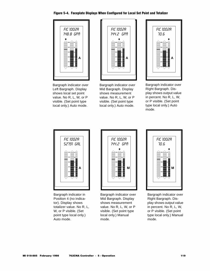
Figure 5-4. Faceplate Displays When Configured for Local Set Point and Totalizer
A
148.8 GPMFIC 1002A
A
144.2 GPMFIC 1002A
A
70.6 FIC 1002A
Bargraph indicator over Left Bargraph. Display shows local set point value. No R, L, W, or P visible. (Set point type local only.) Auto mode.
Bargraph indicator over Mid Bargraph. Display shows measurement value. No R, L, W, or P visible. (Set point type local only.) Auto mode.
Bargraph indicator over Right Bargraph. Dis-play shows output value in percent. No R, L, W, or P visible. (Set point type local only.) Auto mode.
A
52791 GAL
M
144.2 GPMFIC 1002A
M
70.6 FIC 1002A
Bargraph indicator in Position 4 (no indica-tor). Display shows totalizer value. No R, L, W, or P visible. (Set point type local only.) Auto mode.
Bargraph indicator over Mid Bargraph. Display shows measurement value. No R, L, W, or P visible. (Set point type local only.) Manual mode.
Bargraph indicator over Right Bargraph. Dis-play shows output value in percent. No R, L, W, or P visible. (Set point type local only.) Manual mode.
FIC 1002A
MI 018-885 February 1998 762CNA Controller - 5 - Operation 119
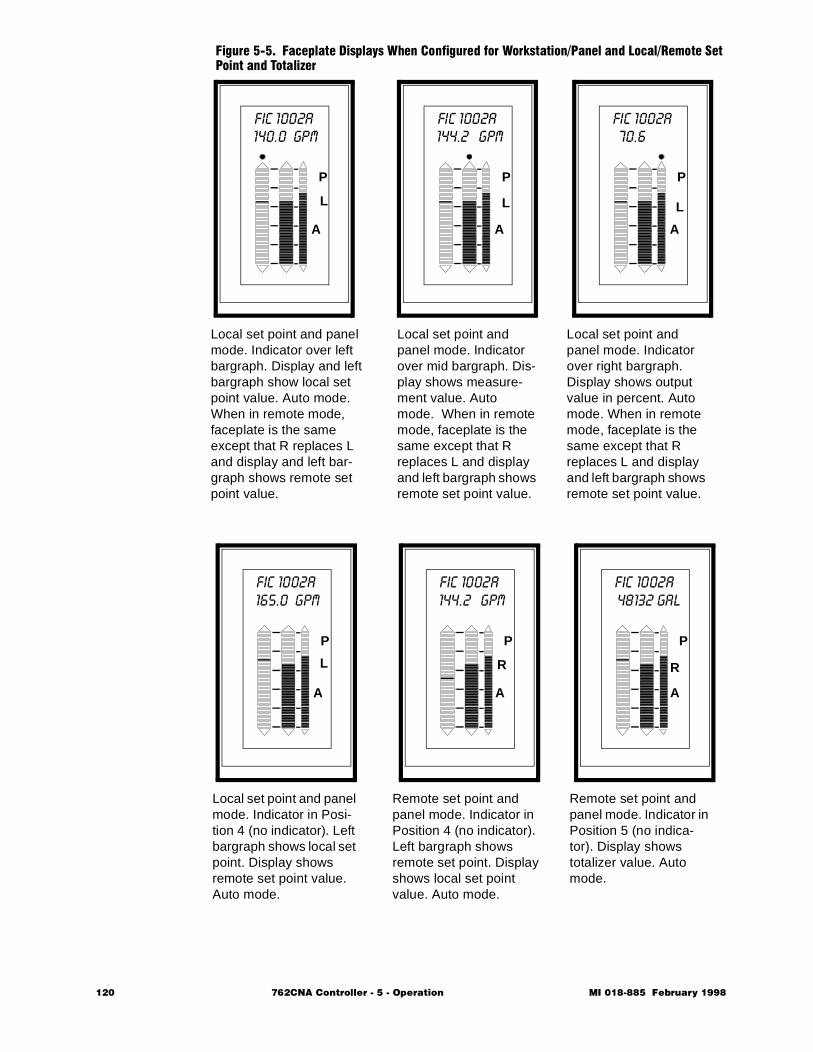
Figure 5-5. Faceplate Displays When Configured for Workstation/Panel and Local/Remote Set Point and Totalizer
P
A
140.0 GPMFIC 1002A
P
A
144.2 GPMFIC 1002A
P
A
70.6 FIC 1002A
Local set point and panel mode. Indicator over left bargraph. Display and left bargraph show local set point value. Auto mode. When in remote mode, faceplate is the same except that R replaces L and display and left bar-graph shows remote set point value.
P
A
165.0 GPM
P
A
144.2 GPMFIC 1002A
P
A
48132 GALFIC 1002A
Local set point and panel mode. Indicator in Posi-tion 4 (no indicator). Left bargraph shows local set point. Display shows remote set point value. Auto mode.
FIC 1002A
LLL
L R
Local set point and panel mode. Indicator over mid bargraph. Dis-play shows measure-ment value. Auto mode. When in remote mode, faceplate is the same except that R replaces L and display and left bargraph shows remote set point value.
Local set point and panel mode. Indicator over right bargraph. Display shows output value in percent. Auto mode. When in remote mode, faceplate is the same except that R replaces L and display and left bargraph shows remote set point value.
Remote set point and panel mode. Indicator in Position 4 (no indicator). Left bargraph shows remote set point. Display shows local set point value. Auto mode.
Remote set point and panel mode. Indicator in Position 5 (no indica-tor). Display shows totalizer value. Auto mode.
R
120 762CNA Controller - 5 - Operation MI 018-885 February 1998

Changing the Control StatusTo switch between Auto and Manual modes, press the A/M key. To switch between Remote and Local set points or between Ratio and Local modes, press the R/L key. For these keys to be active, their respective switches must be configured to NONE. Also, if serial communications are enabled, W/P must be configured to P.To switch between Workstation and Panel operation, press the W/P key. For this key to be active, W/P must be configured ON and W/P PRIORITY must be set to P or BOTH.All transfers except R/L are bumpless. R/L transfer is bumpless if LOCTRK is set. A/M, R/L, and W/P can be switched remotely via respective switches.
NOTE When the controller is placed in Manual, the bargraph indicator moves over the right bargraph (output). When placed in Auto, it moves over the middle bargraph (measurement).
Changing Set Point, Output, and VariablesTo increase or decrease local set point:
1 With controller in local mode, press SEL to select the bargraph display. If the indicator is not over the Left Bargraph, press SEL repeatedly until it is positioned over the Left Bargraph.
2 Press the ∆/∇ keys to change the value. To increase the rate of change in the value, press/hold the key.
Table 5-1 describes how the arrow keys affect controller variables with dif-ferent positions of the bargraph indicator in both automatic and manual modes, when R/L is not configured. Table 5-2 on page 122 defines similar functions when R/L and a totalizer are configured.Table 5-3 on page 123 defines operation in ratio mode.
Table 5-1. Effect of ∆/∇ Keys with R/L Not Configured
Auto/Manual Status
Indicator Above Bargraph
Variable Adjusted by ∆/∇ Keys Comments
Auto Any Bargraph Set PointManual Set Point Set Point Output will not
change.Measurement Output Set point will not
changeOutput Output Set point will not
change
MI 018-885 February 1998 762CNA Controller - 5 - Operation 121
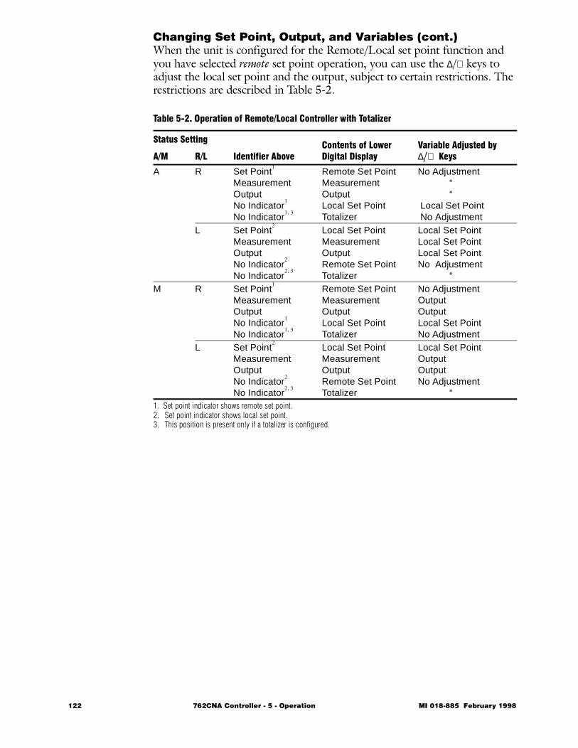
Changing Set Point, Output, and Variables (cont.)When the unit is configured for the Remote/Local set point function and you have selected remote set point operation, you can use the ∆/∇ keys to adjust the local set point and the output, subject to certain restrictions. The restrictions are described in Table 5-2.
1. Set point indicator shows remote set point.2. Set point indicator shows local set point.3. This position is present only if a totalizer is configured.
Table 5-2. Operation of Remote/Local Controller with Totalizer
Status Setting
Identifier AboveContents of Lower Digital Display
Variable Adjusted by ∆/∇ KeysA/M R/L
A R Set Point1
MeasurementOutputNo Indicator
1
No Indicator1, 3
Remote Set PointMeasurementOutputLocal Set PointTotalizer
No Adjustment “ “ Local Set Point No Adjustment
L Set Point2
MeasurementOutputNo Indicator
2
No Indicator2, 3
Local Set PointMeasurementOutputRemote Set PointTotalizer
Local Set PointLocal Set PointLocal Set PointNo Adjustment “
M R Set Point1
MeasurementOutputNo Indicator
1
No Indicator1, 3
Remote Set PointMeasurementOutputLocal Set PointTotalizer
No AdjustmentOutputOutputLocal Set PointNo Adjustment
L Set Point2
MeasurementOutputNo Indicator
2
No Indicator2, 3
Local Set PointMeasurementOutputRemote Set PointTotalizer
Local Set PointOutputOutputNo Adjustment “
122 762CNA Controller - 5 - Operation MI 018-885 February 1998

Changing Set Point, Output, and Variables (cont.)When the unit is configured for the Ratio/Local function and you have selected ratio operation, you can use the ∆/∇ arrow keys to adjust the local set point, output, and ratio gain, subject to certain restrictions. The restric-tions are described in Table 5-3.
1. Ratioed Variable is product of the ratio signal, ratio gain, and range.2. Set point bargraph shows ratioed variable.3. Set point bargraph shows local set point.4. This position is present only if a totalizer is configured.5. If ratio is sourced to faceplate and ratio gain is not cascaded from controller output.
Displaying/Acknowledging Alarms Alarm information (horn symbol alarm indicator) is displayed regardless of which faceplate is in use. If the unit is so configured, alarm points can be displayed in the bargraphs. Typical displays for an absolute measurement high/low alarm with alarm levels indicated are shown in Figure 5-6.
Table 5-3. Operation of Ratio Controller with Totalizer
Status SettingBargraph Identifier Position
Contents of Lower Digital Display
Variable Adjusted by ∆/∇ KeysA/M R/L
A R (Ratio) Set Point2
MeasurementOutputNo Indicator
2
No Indicator4
Ratioed Variable1
MeasurementOutputRatio GainTotalizer
Ratio Gain5
Ratio Gain5
Ratio Gain5
Ratio Gain5
No AdjustmentL (Local) Set Point
3
MeasurementOutputNo Indicator
3
No Indicator4
Local Set PointMeasurementOutputRatioed Variable
1
Totalizer
Local Set PointLocal Set PointLocal Set PointRatio GainNo Adjustment
M R (Ratio) Set Point2
MeasurementOutputNo Indicator
2
No Indicator4
Ratioed Variable1
MeasurementOutputRatio GainTotalizer
Ratio Gain5
OutputOutputRatio Gain
5
No AdjustmentL (Local) Set Point
3
MeasurementOutputNo Indicator
3
No Indicator4
Local Set PointMeasurementOutputRatioed Variable
1
Totalizer
Local Set PointOutputOutputRatio Gain
5
No Adjustment
MI 018-885 February 1998 762CNA Controller - 5 - Operation 123
High/High and Low/Low Alarms
Displays for high/high and low/low types of alarms are similar to those illus-trated for a high/low alarm except for different placement of the alarm points. With rate-of-change alarms, however, no indication appears on the bargraphs. When a rate-of-change alarm is active, only the alarm indicator on the faceplate flashes. When you press the ACK key to acknowledge the alarm, the Lower Digital Display shows the status of the latest active alarm. By pressing ACK repeatedly, you can cycle through the status of all alarms and the current value of the selected variable.
Latching Alarms
If a latching alarm condition occurs, the alarm indicator flashes until you press the ACK key. At this point, the alarm indicator goes out if the alarm condition has ended. If the condition persists, it changes from flashing to steady. The steady alarm indication continues as long as the alarm condition exists.
Non-latching Alarms
If a nonlatching alarm condition occurs, the alarm indicator flashes until you press the ACK key or the alarm condition ends. When the alarm is acknowl-edged, the alarm indicator stops flashing and becomes steady. When the alarm condition ends, the alarm indicator goes out.
Acknow-ledging Alarms
After you acknowledge an alarm, the condition causing the alarm is identi-fied by a flashing message in the lower line of the alphanumeric display. The message continues to flash as long as the alarm condition exists, or until you press the ACK key again. When you press the ACK key a second time, the message disappears and the value of the previously selected bargraph is again displayed.
Multiple Alarms
If more than one alarm condition exists, you can identify each condition in turn by pressing the ACK key repeatedly. After all active alarm conditions have been identified, the previously selected bargraph value is displayed. The alarm indicator, however, continues to be illuminated. You can again display the identifications of the alarm conditions by repeatedly pressing the ACK key. If an alarm condition no longer exists, it is removed from the alarm queue.
Audible Warning
Alarms may be assigned to one or two contact outputs to drive a horn bus. With a latching alarm, the alarm contact output resets when the alarm con-dition is ACKnowledged and the alarm condition returns to normal. With a nonlatching alarm, the alarm contact resets when the alarm condition is ACKnowledged or the alarm condition returns to normal, whichever is first. With a permissive alarm, no visual indication is provided. However, the alarm contact is active.In addition to connecting to a contact output, the boolean output of the alarm, can be used anywhere any other signal in the Gate Input List can be used.
124 762CNA Controller - 5 - Operation MI 018-885 February 1998
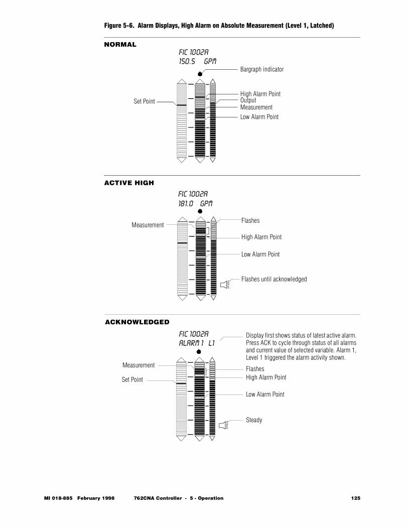
Figure 5-6. Alarm Displays, High Alarm on Absolute Measurement (Level 1, Latched)
ACTIVE HIGH
High Alarm PointSet Point Output
MeasurementLow Alarm Point
Bargraph indicator
Low Alarm Point
High Alarm Point
Flashes
Low Alarm Point
High Alarm PointFlashes
Steady
FIC 1002A150.5 GPM
181.0 GPM
ALARM 1 L1
FIC 1002A
FIC 1002A Display first shows status of latest active alarm. Press ACK to cycle through status of all alarms and current value of selected variable. Alarm 1, Level 1 triggered the alarm activity shown.
Measurement
NORMAL
ACKNOWLEDGED
Flashes until acknowledged
Measurement
Set Point
MI 018-885 February 1998 762CNA Controller - 5 - Operation 125
Changing Alarm SettingsIf you are authorized to do so, you can increase and decrease alarm settings from OPTUNE (Refer to the Structure Diagram on page 241). You can also do this from ALLTUNE if you have entered the passcode.To change the alarm setting for Alarm 1 Level 2, refer to Structure Diagram shown on page 241 and execute the following procedure:1 Starting in NORMAL mode, press TAG to go to READ, then ∇
to go to SET mode.2 If not configured for alarms to be present in OPTUNE, press ∇ to go
to SECURE. Then press ACK to display PASSCODE =?. Enter passcode and press ACK to move to ALLTUNE. Go to Step 4.
3 Press ACK to go to OPTUNE, if configured for alarms to be present in OPTUNE.
4 Press ACK to go to TUNE C1.5 Press ∇ repeatedly until display shows ALARMS.6 Press ACK to go to ALARM 1.7 Press ACK to go to LEVEL 1 =?.8 Press ∆/∇ keys to adjust LEVEL 1. Press ACK to enter setting.9 Press ACK to go to ALARM 1 LEVEL 2. The lower display will
show the current setting for ALARM 1 LEVEL 2.10 Press ∆/∇ keys to increase or decrease the LEVEL 2 setting. When
desired value is displayed, press ACK to accept the setting.11 Press ACK to go to ALARM DEADBAND.12 Press ∆/∇ keys to increase or decrease deadband. Press ACK to enter
setting.13 Press TAG to return to NORMAL operation.
126 762CNA Controller - 5 - Operation MI 018-885 February 1998
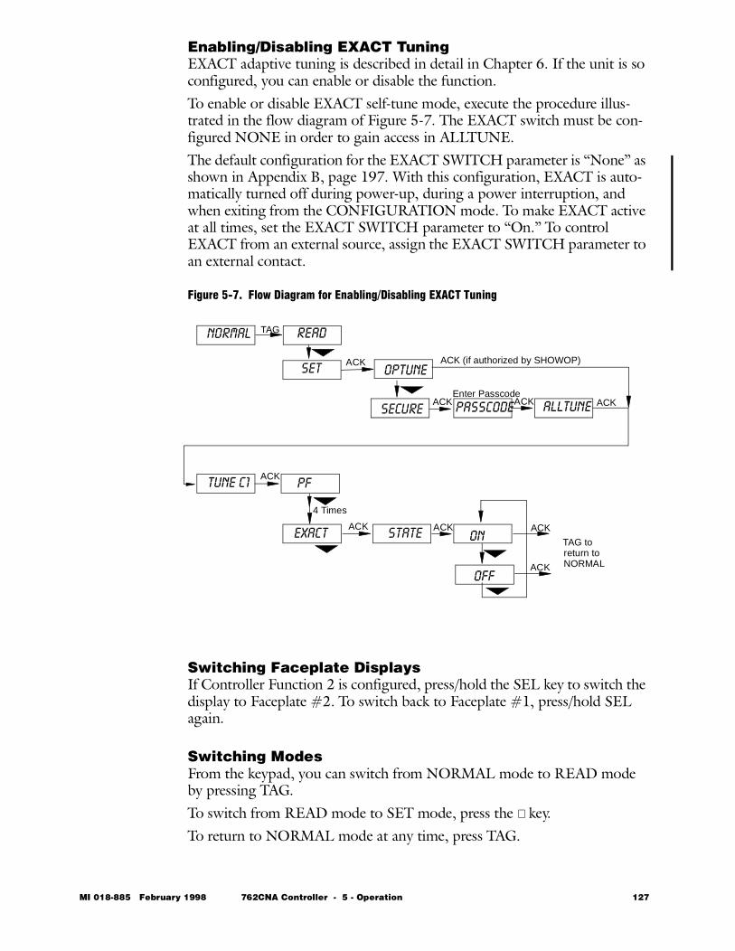
Enabling/Disabling EXACT TuningEXACT adaptive tuning is described in detail in Chapter 6. If the unit is so configured, you can enable or disable the function. To enable or disable EXACT self-tune mode, execute the procedure illus-trated in the flow diagram of Figure 5-7. The EXACT switch must be con-figured NONE in order to gain access in ALLTUNE.The default configuration for the EXACT SWITCH parameter is “None” as shown in Appendix B, page 197. With this configuration, EXACT is auto-matically turned off during power-up, during a power interruption, and when exiting from the CONFIGURATION mode. To make EXACT active at all times, set the EXACT SWITCH parameter to “On.” To control EXACT from an external source, assign the EXACT SWITCH parameter to an external contact.
Figure 5-7. Flow Diagram for Enabling/Disabling EXACT Tuning
Switching Faceplate Displays If Controller Function 2 is configured, press/hold the SEL key to switch the display to Faceplate #2. To switch back to Faceplate #1, press/hold SEL again.
Switching ModesFrom the keypad, you can switch from NORMAL mode to READ mode by pressing TAG. To switch from READ mode to SET mode, press the ∇ key. To return to NORMAL mode at any time, press TAG.
TAG
ACK
ACK ACK ACK
ACK
ACK ACK ACK
return toNORMAL
NORMAL READ
SET OPTUNE
SECURE PASSCODEEnter Passcode
TUNE C1
ALLTUNE
PF =
EXACT
4 Times
STATE ON
OFF
ACK (if authorized by SHOWOP)
ACK
TAG to
MI 018-885 February 1998 762CNA Controller - 5 - Operation 127

Operation as an Auto/Manual StationEither or both functions of the 762CNA can be configured as Auto/Manual Stations. When an A/M Station is configured, operation is essentially the same as when a controller is configured, except that no control algorithm is computed. This means that all features and configuration options other than a control algorithm are available for use.When in Auto mode, the output is equal to its configured source value. The measurement input is then displayed on the middle bargraph and the output on the right bargraph. The left bargraph displays an assigned value, if con-figured. Use the SEL key to view the value on the lower digital display. The factory default is a blanked bargraph.In Manual mode, the output is determined by use of the ∆/∇ keys as in a controller. If dual functions are configured, use the “Switching Faceplate Displays” procedure described on the previous page.
128 762CNA Controller - 5 - Operation MI 018-885 February 1998
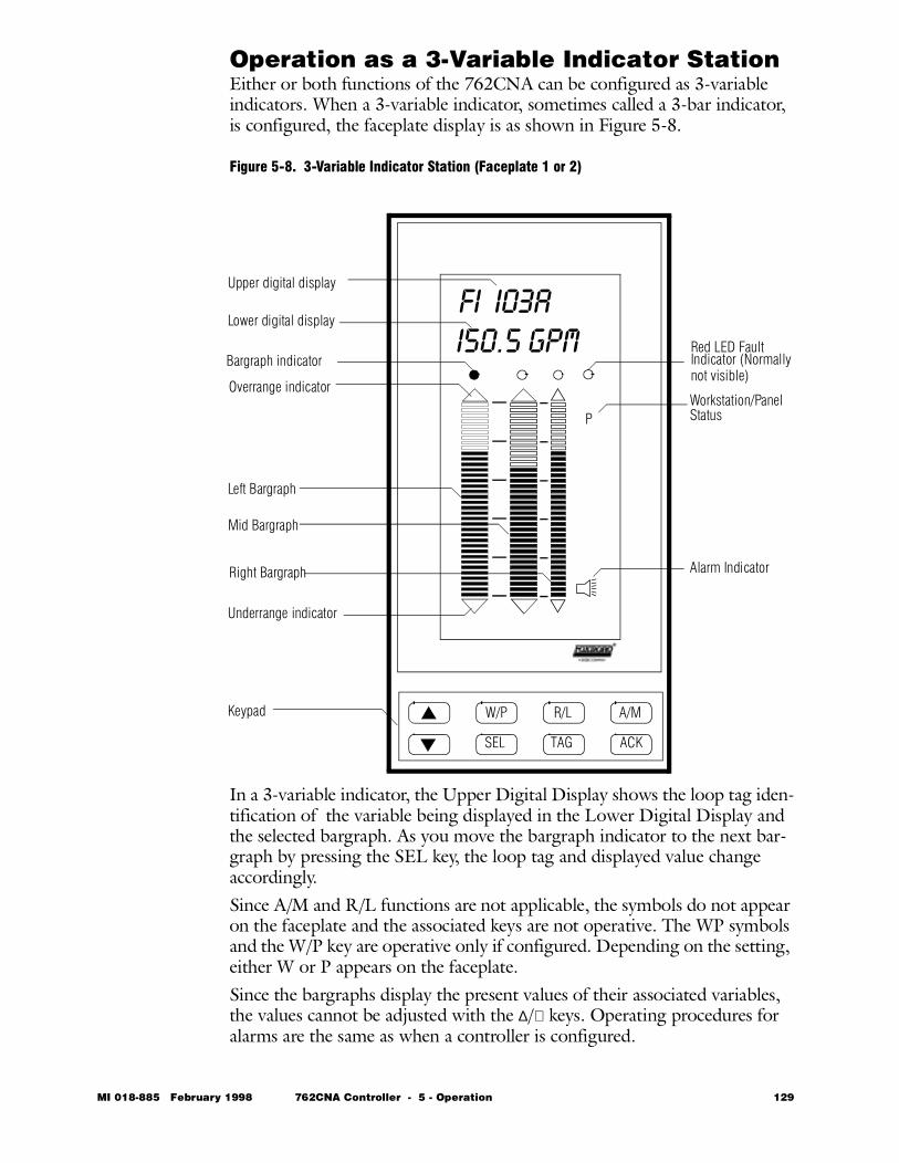
Operation as a 3-Variable Indicator StationEither or both functions of the 762CNA can be configured as 3-variable indicators. When a 3-variable indicator, sometimes called a 3-bar indicator, is configured, the faceplate display is as shown in Figure 5-8.
Figure 5-8. 3-Variable Indicator Station (Faceplate 1 or 2)
In a 3-variable indicator, the Upper Digital Display shows the loop tag iden-tification of the variable being displayed in the Lower Digital Display and the selected bargraph. As you move the bargraph indicator to the next bar-graph by pressing the SEL key, the loop tag and displayed value change accordingly. Since A/M and R/L functions are not applicable, the symbols do not appear on the faceplate and the associated keys are not operative. The WP symbols and the W/P key are operative only if configured. Depending on the setting, either W or P appears on the faceplate.Since the bargraphs display the present values of their associated variables, the values cannot be adjusted with the ∆/∇ keys. Operating procedures for alarms are the same as when a controller is configured.
P
W/P R/L A/M
SEL TAG ACK
Overrange indicator
Upper digital display
Lower digital display
Bargraph indicator
Underrange indicator
Left Bargraph
Mid Bargraph
Right Bargraph
Workstation/Panel
Alarm Indicator
Status
Red LED FaultIndicator (Normally
Keypad
FI I03A I50.5 GPM
not visible)
MI 018-885 February 1998 762CNA Controller - 5 - Operation 129
Operation as an Auto-Selector StationWhen the unit is configured as a single-station auto-selector, two controllers alternately control a single output. Control shifts smoothly from one to the other depending on how the loops are configured and operated. Selection can be high select, low select, or event-driven (via GATE 4). Feedback from the output is provided to prevent windup in the controller that is currently not selected for control.When viewing the faceplate of the unselected controller, the operator sees a flashing AM indicator.
Operation as a Cascade Control StationWhen the unit is configured as a single-station cascade control station, Con-troller 1 is configured as the primary controller and Controller 2 is the sec-ondary or slave controller. The output of Controller 1, therefore, is used as the remote set point or ratio gain for Controller 2. The output of Controller 2 controls the valve or other actuator.The AM status indicator flashes to indicate an open loop condition in a cas-cade primary loop when the secondary is in Manual, Local, or OUTTRK.
130 762CNA Controller - 5 - Operation MI 018-885 February 1998
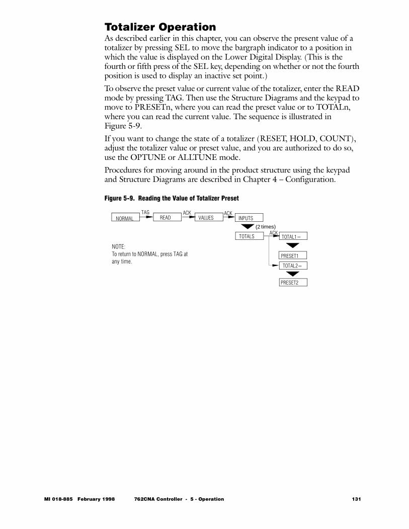
Totalizer OperationAs described earlier in this chapter, you can observe the present value of a totalizer by pressing SEL to move the bargraph indicator to a position in which the value is displayed on the Lower Digital Display. (This is the fourth or fifth press of the SEL key, depending on whether or not the fourth position is used to display an inactive set point.)To observe the preset value or current value of the totalizer, enter the READ mode by pressing TAG. Then use the Structure Diagrams and the keypad to move to PRESETn, where you can read the preset value or to TOTALn, where you can read the current value. The sequence is illustrated in Figure 5-9.If you want to change the state of a totalizer (RESET, HOLD, COUNT), adjust the totalizer value or preset value, and you are authorized to do so, use the OPTUNE or ALLTUNE mode. Procedures for moving around in the product structure using the keypad and Structure Diagrams are described in Chapter 4 – Configuration.
Figure 5-9. Reading the Value of Totalizer Preset
NORMAL READ
TOTALS TOTAL1=
PRESET1
VALUES
TOTAL2=
TAG ACK ACK
ACK
PRESET2
NOTE:To return to NORMAL, press TAG at any time.
(2 times)
INPUTS
MI 018-885 February 1998 762CNA Controller - 5 - Operation 131
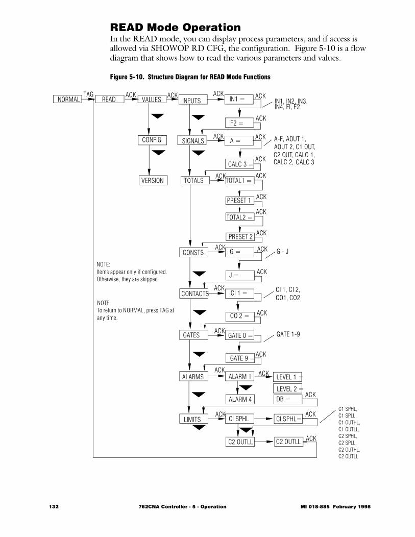
READ Mode OperationIn the READ mode, you can display process parameters, and if access is allowed via SHOWOP RD CFG, the configuration. Figure 5-10 is a flow diagram that shows how to read the various parameters and values.
Figure 5-10. Structure Diagram for READ Mode Functions
NORMAL READ
TOTALS TOTAL1 =
VALUES
TOTAL2 =
INPUTS
SIGNALS
CONSTS
CONTACTS
GATES
ALARMS
LIMITS
IN1 =
F2 =
A =
CALC 3 =
G =
J =
CI 1 =
CO 2 =
GATE 0 =
GATE 9 =
ALARM 1
ALARM 4
CI SPHL
C2 OUTLL
LEVEL 1 =
DB =
TAG ACK ACK
ACK
ACK
ACK
ACK
ACK
ACK
ACK
IN1, IN2, IN3,IN4, FI, F2
A-F, AOUT 1,
CI 1, CI 2,
AOUT 2, C1 OUT,C2 OUT, CALC 1,
LEVEL 2 =
NOTE:To return to NORMAL, press TAG at any time.
PRESET 2
ACK
ACK
G - J
GATE 1-9
CO1, CO2
ACK
ACK
ACK
ACK
ACK
ACK
ACK
ACK
CALC 2, CALC 3
ACK
ACK
ACK
PRESET 1
ACK
ACK
ACK
ACK
CI SPHL=
C2 OUTLL =
C1 SPHL,C1 SPLL, C1 OUTHL, C1 OUTLL, C2 SPHL, C2 SPLL, C2 OUTHL, C2 OUTLL
NOTE:Items appear only if configured. Otherwise, they are skipped.
CONFIG
VERSION
132 762CNA Controller - 5 - Operation MI 018-885 February 1998

762C SINGLESTATION
MICROController
February 1998
Preface • xiii Chapter 1 Quick Check • 1 Chapter 2 Product Overview • 11 Chapter 3 Installation • 23 Chapter 4 Configuration • 49 Chapter 5 Operation • 109
Ð Chapter 6 EXACT Tuning • 135 Chapter 7 Calibration, Troubleshooting,
Maintenance • 159 Appendix A Specifications • 183 Appendix B Configuration Worksheets • 193 Appendix C Structure Diagrams • 237 Appendix D Parts List • 247 Appendix E Dimensional Print • 255 Appendix F Functional Diagram • 261 Glossary • 267 Index • 287
The Intelligent Automation People

134 762CNA Controller MI 018-885 February 1998
MI 018-885 Februar
6 EXACT Tuning
This chapter describes the Foxboro patented EXACT adaptive tuning system, a feature of the 762CNA controller. The chapter is divided into the following major sections:• Technical Description • 136 • Using EXACT Tuning with 762C Controllers • 144 • Tutorial Example • 150 • Tables and Structure Diagrams • 155
y 1998 762CNA Controller - 6 - EXACT Tuning 135
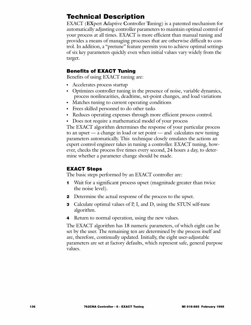
Technical Description EXACT (EXpert Adaptive Controller Tuning) is a patented mechanism for automatically adjusting controller parameters to maintain optimal control of your process at all times. EXACT is more efficient than manual tuning and provides a means of managing processes that are otherwise difficult to con-trol. In addition, a “pretune” feature permits you to achieve optimal settings of six key parameters quickly even when initial values vary widely from the target.
Benefits of EXACT TuningBenefits of using EXACT tuning are:• Accelerates process startup• Optimizes controller tuning in the presence of noise, variable dynamics,
process nonlinearities, deadtime, set-point changes, and load variations• Matches tuning to current operating conditions• Frees skilled personnel to do other tasks• Reduces operating expenses through more efficient process control.• Does not require a mathematical model of your processThe EXACT algorithm determines the response of your particular process to an upset — a change in load or set point — and calculates new tuning parameters automatically. This technique closely emulates the actions an expert control engineer takes in tuning a controller. EXACT tuning, how-ever, checks the process five times every second, 24 hours a day, to deter-mine whether a parameter change should be made.
EXACT StepsThe basic steps performed by an EXACT controller are:
1 Wait for a significant process upset (magnitude greater than twice the noise level).
2 Determine the actual response of the process to the upset.3 Calculate optimal values of P, I, and D, using the STUN self-tune
algorithm.4 Return to normal operation, using the new values.The EXACT algorithm has 18 numeric parameters, of which eight can be set by the user. The remaining ten are determined by the process itself and are, therefore, continually updated. Initially, the eight user-adjustable parameters are set at factory defaults, which represent safe, general purpose values.
136 762CNA Controller - 6 - EXACT Tuning MI 018-885 February 1998
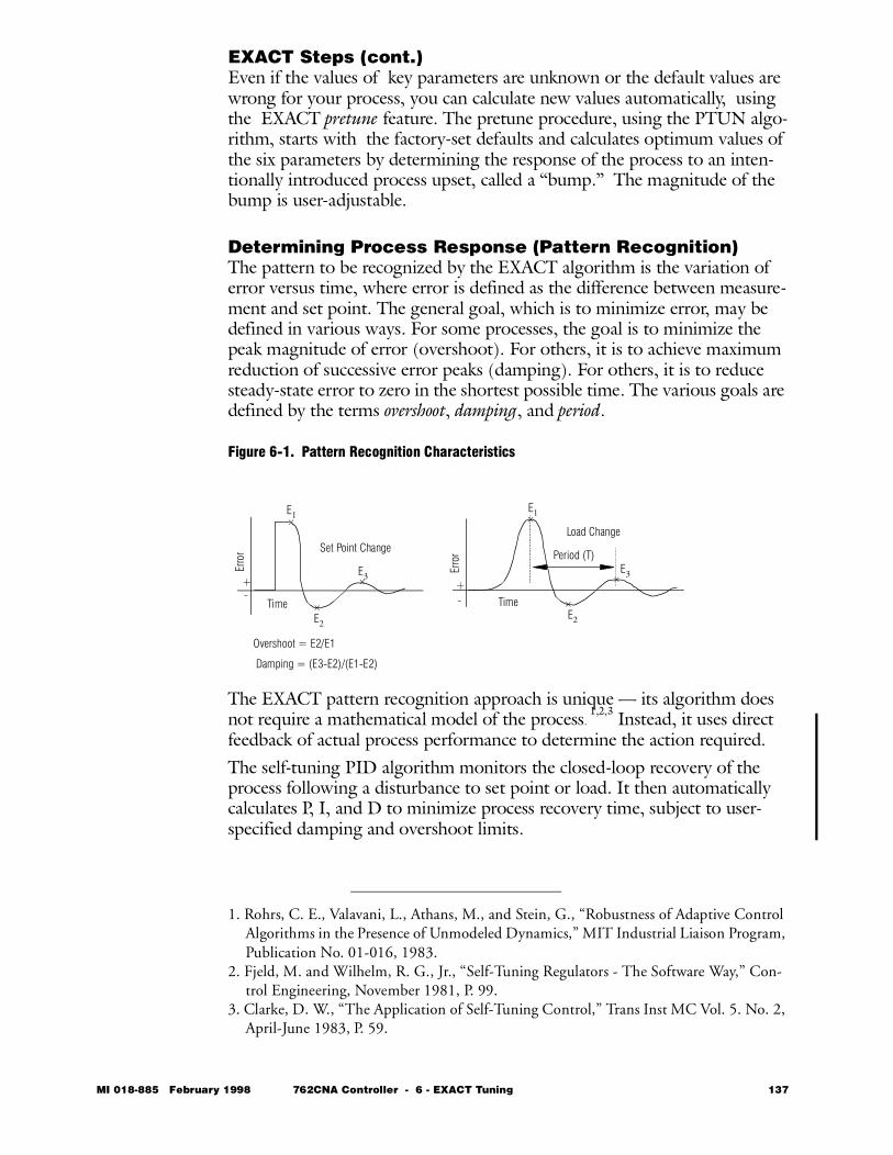
EXACT Steps (cont.)Even if the values of key parameters are unknown or the default values are wrong for your process, you can calculate new values automatically, using the EXACT pretune feature. The pretune procedure, using the PTUN algo-rithm, starts with the factory-set defaults and calculates optimum values of the six parameters by determining the response of the process to an inten-tionally introduced process upset, called a “bump.” The magnitude of the bump is user-adjustable.
Determining Process Response (Pattern Recognition)The pattern to be recognized by the EXACT algorithm is the variation of error versus time, where error is defined as the difference between measure-ment and set point. The general goal, which is to minimize error, may be defined in various ways. For some processes, the goal is to minimize the peak magnitude of error (overshoot). For others, it is to achieve maximum reduction of successive error peaks (damping). For others, it is to reduce steady-state error to zero in the shortest possible time. The various goals are defined by the terms overshoot, damping, and period.
Figure 6-1. Pattern Recognition Characteristics
The EXACT pattern recognition approach is unique — its algorithm does not require a mathematical model of the process.
1,2,3 Instead, it uses direct feedback of actual process performance to determine the action required. The self-tuning PID algorithm monitors the closed-loop recovery of the process following a disturbance to set point or load. It then automatically calculates P, I, and D to minimize process recovery time, subject to user-specified damping and overshoot limits.
1. Rohrs, C. E., Valavani, L., Athans, M., and Stein, G., “Robustness of Adaptive Control Algorithms in the Presence of Unmodeled Dynamics,” MIT Industrial Liaison Program, Publication No. 01-016, 1983.
2. Fjeld, M. and Wilhelm, R. G., Jr., “Self-Tuning Regulators - The Software Way,” Con-trol Engineering, November 1981, P. 99.
3. Clarke, D. W., “The Application of Self-Tuning Control,” Trans Inst MC Vol. 5. No. 2, April-June 1983, P. 59.
Set Point Change
E3
Time
Erro
r
Erro
r
Time
E3
E2
E1
E2
Period (T)
Load Change
+-
+-
Overshoot = E2/E1
Damping = (E3-E2)/(E1-E2)
E1
MI 018-885 February 1998 762CNA Controller - 6 - EXACT Tuning 137
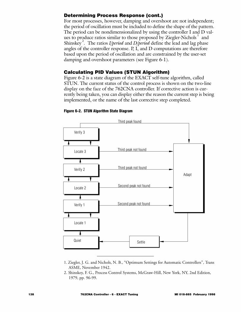
Determining Process Response (cont.)For most processes, however, damping and overshoot are not independent; the period of oscillation must be included to define the shape of the pattern. The period can be nondimensionalized by using the controller I and D val-ues to produce ratios similar to those proposed by Ziegler-Nichols
1 and Shinskey
2. The ratios I/period and D/period define the lead and lag phase angles of the controller response. P, I, and D computations are therefore based upon the period of oscillation and are constrained by the user-set damping and overshoot parameters (see Figure 6-1).
Calculating PID Values (STUN Algorithm)Figure 6-2 is a state diagram of the EXACT self-tune algorithm, called STUN. The current status of the control process is shown on the two-line display on the face of the 762CNA controller. If corrective action is cur-rently being taken, you can display either the reason the current step is being implemented, or the name of the last corrective step completed.
Figure 6-2. STUN Algorithm State Diagram
1. Ziegler, J. G. and Nichols, N. B., “Optimum Settings for Automatic Controllers”, Trans ASME, November 1942.
2. Shinskey, F. G., Process Control Systems, McGraw-Hill, New York, NY, 2nd Edition, 1979, pp. 96-99.
Third peak found
Third peak not found
Third peak not found
Second peak not found
Second peak not found
Verify 3
Locate 3
Verify 2
Locate 2
Locate 1
Verify 1
Quiet Settle
Adapt
138 762CNA Controller - 6 - EXACT Tuning MI 018-885 February 1998
LocatingPeak 1
In normal operation, set point and measurement are close to each other and the algorithm is in the QUIET state (error is too small to activate the self-tune algorithm). However, when a disturbance appears in the process that causes the error to exceed twice the noise band, the algorithm “wakes up” and begins to “watch” the error in anticipation of a peak. While waiting for the first peak, the state is defined as LOCATE 1. Once a peak occurs, the algorithm stores the magnitude of the peak and starts a timer to record the elapsed time to the next peak, which is defined as the period of oscillation.
Ziegler-NicholsMethod
Ziegler-Nichols developed a tuning procedure that involved adjusting I and D until I/period equals 0.5 and D/period equals 0.12. However, it has since been found that much better tuning and quicker convergence result when the ratios of I/period and D/period are changed by the algorithm. A process with a dominant deadtime requires smaller ratio values than one with a dominant lag. If the response is overdamped and distinct peaks are not found, I and D are adjusted by applying expert rules.
Verifying Peak 1
Before searching for Peak 2, the algorithm verifies that the first is a true peak (during the VERIFY 1 state). If a new extreme value occurs during this verification state, it then becomes the first peak and the timer is restarted.
Locating Peaks 2 and 3
After Peak 1 occurs and is verified, the algorithm uses the same method to locate and verify Peaks 2 and 3.
Damping, Overshoot, and Period
The peak information is then expressed in the previously-defined terms of “overshoot”, “damping”, “I/period”, and “D/period.” Validity is deter-mined for this information based upon the height of the peaks relative to the nominal noise band and the time between peaks relative to the period of a nominal damped sinusoid.When the loop is properly tuned, the values of P, I, and D remain essentially unchanged from disturbance to disturbance. However, if the disturbance changes shape or if the process changes, EXACT will automatically deter-mine new values.
CalculatingP, I, D
Up to this point, the controller is operating as a fixed parameter PID con-troller. However, it has observed the loop response to a disturbance. The algorithm then uses the response information to calculate new values of P, I, and D (during the ADAPT state). The first step in calculating new P, I, and D values uses the period information to set I and D directly and damping or overshoot error to adjust P. The interaction between P, I, and D, however, requires this algorithm to be slightly more sophisticated — P must be fur-ther adjusted to compensate for the changes in I and D values.
MI 018-885 February 1998 762CNA Controller - 6 - EXACT Tuning 139
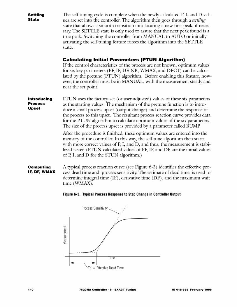
SettlingState
The self-tuning cycle is complete when the newly calculated P, I, and D val-ues are set into the controller. The algorithm then goes through a settling state that allows a smooth transition into locating a new first peak, if neces-sary. The SETTLE state is only used to assure that the next peak found is a true peak. Switching the controller from MANUAL to AUTO or initially activating the self-tuning feature forces the algorithm into the SETTLE state.
Calculating Initial Parameters (PTUN Algorithm)If the control characteristics of the process are not known, optimum values for six key parameters (PF, IF, DF, NB, WMAX, and DFCT) can be calcu-lated by the pretune (PTUN) algorithm. Before enabling this feature, how-ever, the controller must be in MANUAL, with the measurement steady and near the set point.
IntroducingProcess Upset
PTUN uses the factory-set (or user-adjusted) values of these six parameters as the starting values. The mechanism of the pretune function is to intro-duce a small process upset (output change) and determine the response of the process to this upset. The resultant process reaction curve provides data for the PTUN algorithm to calculate optimum values of the six parameters. The size of the process upset is provided by a parameter called BUMP.After the procedure is finished, these optimum values are entered into the memory of the controller. In this way, the self-tune algorithm then starts with more correct values of P, I, and D, and thus, the measurement is stabi-lized faster. (PTUN-calculated values of PF, IF, and DF are the initial values of P, I, and D for the STUN algorithm.)
ComputingIF, DF, WMAX
A typical process reaction curve (see Figure 6-3) identifies the effective pro-cess dead time and process sensitivity. The estimate of dead time is used to determine integral time (IF), derivative time (DF), and the maximum wait time (WMAX).
Figure 6-3. Typical Process Response to Step Change in Controller Output
Td = Effective Dead Time
Mea
sure
men
t
Process Sensitivity
Time
140 762CNA Controller - 6 - EXACT Tuning MI 018-885 February 1998
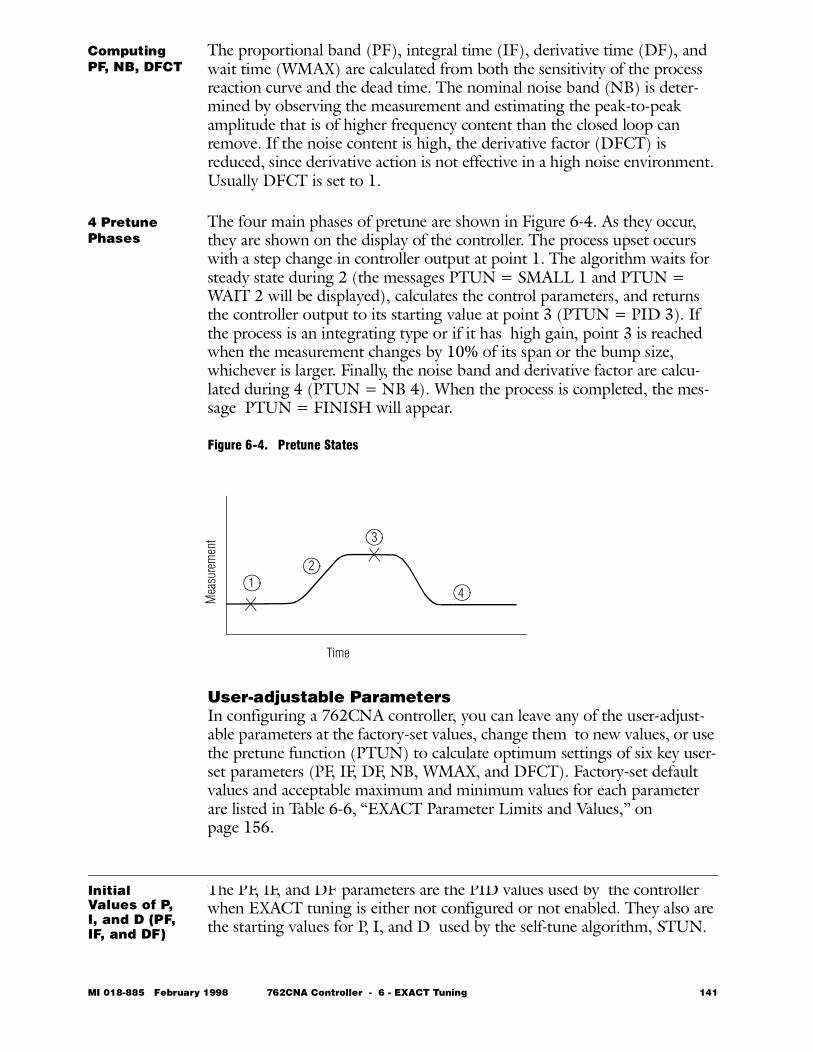
Computing PF, NB, DFCT
The proportional band (PF), integral time (IF), derivative time (DF), and wait time (WMAX) are calculated from both the sensitivity of the process reaction curve and the dead time. The nominal noise band (NB) is deter-mined by observing the measurement and estimating the peak-to-peak amplitude that is of higher frequency content than the closed loop can remove. If the noise content is high, the derivative factor (DFCT) is reduced, since derivative action is not effective in a high noise environment. Usually DFCT is set to 1.
4 Pretune Phases
The four main phases of pretune are shown in Figure 6-4. As they occur, they are shown on the display of the controller. The process upset occurs with a step change in controller output at point 1. The algorithm waits for steady state during 2 (the messages PTUN = SMALL 1 and PTUN = WAIT 2 will be displayed), calculates the control parameters, and returns the controller output to its starting value at point 3 (PTUN = PID 3). If the process is an integrating type or if it has high gain, point 3 is reached when the measurement changes by 10% of its span or the bump size, whichever is larger. Finally, the noise band and derivative factor are calcu-lated during 4 (PTUN = NB 4). When the process is completed, the mes-sage PTUN = FINISH will appear.
Figure 6-4. Pretune States
User-adjustable ParametersIn configuring a 762CNA controller, you can leave any of the user-adjust-able parameters at the factory-set values, change them to new values, or use the pretune function (PTUN) to calculate optimum settings of six key user-set parameters (PF, IF, DF, NB, WMAX, and DFCT). Factory-set default values and acceptable maximum and minimum values for each parameter are listed in Table 6-6, “EXACT Parameter Limits and Values,” on page 156.
Initial Values of P, I, and D (PF, IF, and DF)
The PF, IF, and DF parameters are the PID values used by the controller when EXACT tuning is either not configured or not enabled. They also are the starting values for P, I, and D used by the self-tune algorithm, STUN.
Time
Mea
sure
men
t
12
3
4
MI 018-885 February 1998 762CNA Controller - 6 - EXACT Tuning 141
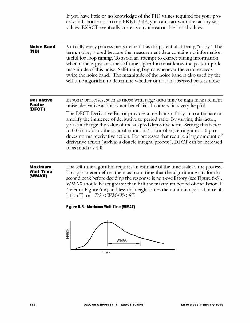
If you have little or no knowledge of the PID values required for your pro-cess and choose not to run PRETUNE, you can start with the factory-set values. EXACT eventually corrects any unreasonable initial values.
Noise Band (NB)
Virtually every process measurement has the potential of being “noisy.” The term, noise, is used because the measurement data contains no information useful for loop tuning. To avoid an attempt to extract tuning information when none is present, the self-tune algorithm must know the peak-to-peak magnitude of this noise. Self-tuning begins whenever the error exceeds twice the noise band. The magnitude of the noise band is also used by the self-tune algorithm to determine whether or not an observed peak is noise.
Derivative Factor (DFCT)
In some processes, such as those with large dead time or high measurement noise, derivative action is not beneficial. In others, it is very helpful.The DFCT Derivative Factor provides a mechanism for you to attenuate or amplify the influence of derivative to period ratio. By varying this factor, you can change the value of the adapted derivative term. Setting this factor to 0.0 transforms the controller into a PI controller; setting it to 1.0 pro-duces normal derivative action. For processes that require a large amount of derivative action (such as a double integral process), DFCT can be increased to as much as 4.0.
Maximum Wait Time (WMAX)
The self-tune algorithm requires an estimate of the time scale of the process. This parameter defines the maximum time that the algorithm waits for the second peak before deciding the response is non-oscillatory (see Figure 6-5). WMAX should be set greater than half the maximum period of oscillation T (refer to Figure 6-6) and less than eight times the minimum period of oscil-lation T, or T/2 <WMAX< 8T.
Figure 6-5. Maximum Wait Time (WMAX)
TIME
ERRO
R
WMAX
142 762CNA Controller - 6 - EXACT Tuning MI 018-885 February 1998
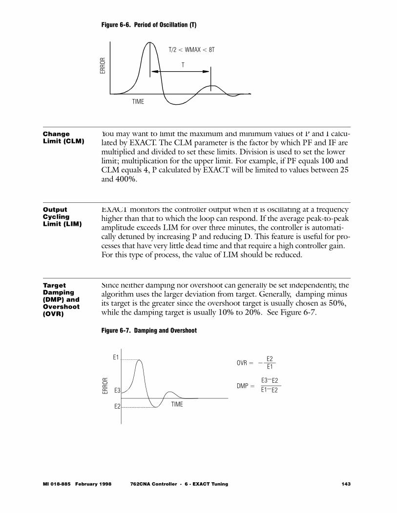
Figure 6-6. Period of Oscillation (T)
Change Limit (CLM)
You may want to limit the maximum and minimum values of P and I calcu-lated by EXACT. The CLM parameter is the factor by which PF and IF are multiplied and divided to set these limits. Division is used to set the lower limit; multiplication for the upper limit. For example, if PF equals 100 and CLM equals 4, P calculated by EXACT will be limited to values between 25 and 400%.
Output Cycling Limit (LIM)
EXACT monitors the controller output when it is oscillating at a frequency higher than that to which the loop can respond. If the average peak-to-peak amplitude exceeds LIM for over three minutes, the controller is automati-cally detuned by increasing P and reducing D. This feature is useful for pro-cesses that have very little dead time and that require a high controller gain. For this type of process, the value of LIM should be reduced.
Target Damping (DMP) and Overshoot (OVR)
Since neither damping nor overshoot can generally be set independently, the algorithm uses the larger deviation from target. Generally, damping minus its target is the greater since the overshoot target is usually chosen as 50%, while the damping target is usually 10% to 20%. See Figure 6-7.
Figure 6-7. Damping and Overshoot
TIMEER
ROR
T
T/2 < WMAX < 8T
TIME
ERRO
R
E1
E2
E3
OVR = E2
DMP = E3 E2
E1
E1 E2
MI 018-885 February 1998 762CNA Controller - 6 - EXACT Tuning 143
BUMP Parameter
The PTUN function uses the BUMP parameter to introduce a small pro-cess upset for generating data for input to STUN. The value entered deter-mines the magnitude and direction of the upset. The BUMP value, however, should not be so large that it drives the output off scale. For example, if the output is at 6% of scale, with the measurement steady and near the set point, a BUMP value of -8% would drive the output off scale (to -2%). Therefore, its value is automatically decreased to -6%. If the BUMP value is too small to activate the pretune algorithm, the error mes-sage PTUN = SMALL 1 will not disappear. In this case, the BUMP should be increased and PTUN rerun.
Using EXACT Tuning with 762C ControllersTable 6-5, “EXACT Parameters,” on page 155 defines the parameters used by EXACT. Table 6-6, “EXACT Parameter Limits and Values,” on page 156 defines limits and default values for each. In both tables, the parameters are listed in the same sequence in which they appear in the display.
Use of Structure DiagramsStructure diagrams illustrate graphically the sequence in which displays appear on the face of the 762CNA controller as you press various keys. A structure diagram is a map of the product structure that enables you to move easily from one parameter or display to another.To enter the structure from normal operating mode, press TAG. You can then move around within the structure by using ACK, SEL, and the ∆/∇keys. To leave the structure and return to normal operation, press TAG at any time.While you are in the structure (after pressing TAG), use ACK to accept a displayed value or to move to the right or to the next item in the diagram. Use SEL to step to the left or backward in minor increments. Use the ∆/∇keys to display a different value in a sequence or to move directly up or down to a different location in the structure. Key functions are described in more detail in Table 6-1.Figure 6-8, which is an excerpt from Structure Diagram 4 (see page 241), shows the part of the 762CNA configuration sequence that pertains to EXACT.
144 762CNA Controller - 6 - EXACT Tuning MI 018-885 February 1998
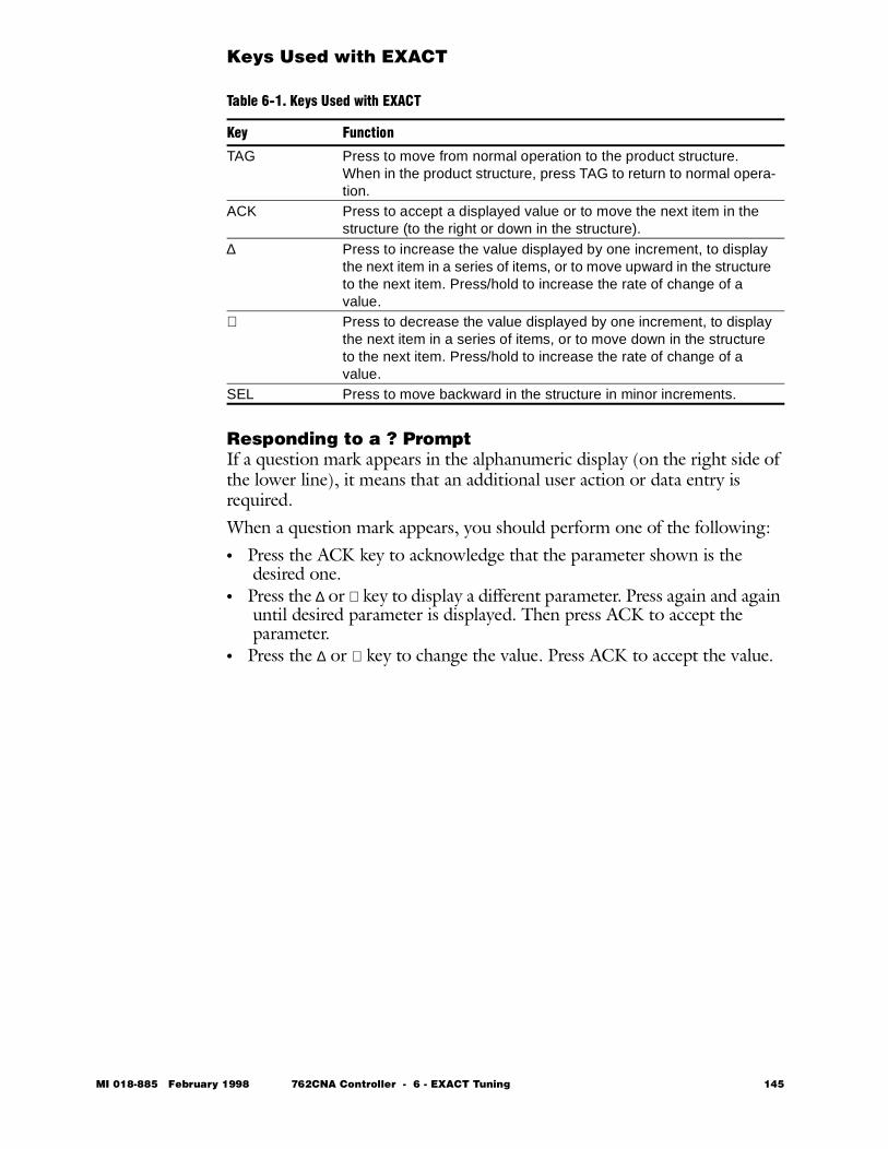
Keys Used with EXACT
Responding to a ? Prompt If a question mark appears in the alphanumeric display (on the right side of the lower line), it means that an additional user action or data entry is required. When a question mark appears, you should perform one of the following: • Press the ACK key to acknowledge that the parameter shown is the
desired one.• Press the ∆ or ∇ key to display a different parameter. Press again and again
until desired parameter is displayed. Then press ACK to accept the parameter.
• Press the ∆ or ∇ key to change the value. Press ACK to accept the value.
Table 6-1. Keys Used with EXACT
Key Function
TAG Press to move from normal operation to the product structure. When in the product structure, press TAG to return to normal opera-tion.
ACK Press to accept a displayed value or to move the next item in the structure (to the right or down in the structure).
∆ Press to increase the value displayed by one increment, to display the next item in a series of items, or to move upward in the structure to the next item. Press/hold to increase the rate of change of a value.
∇ Press to decrease the value displayed by one increment, to display the next item in a series of items, or to move down in the structure to the next item. Press/hold to increase the rate of change of a value.
SEL Press to move backward in the structure in minor increments.
MI 018-885 February 1998 762CNA Controller - 6 - EXACT Tuning 145
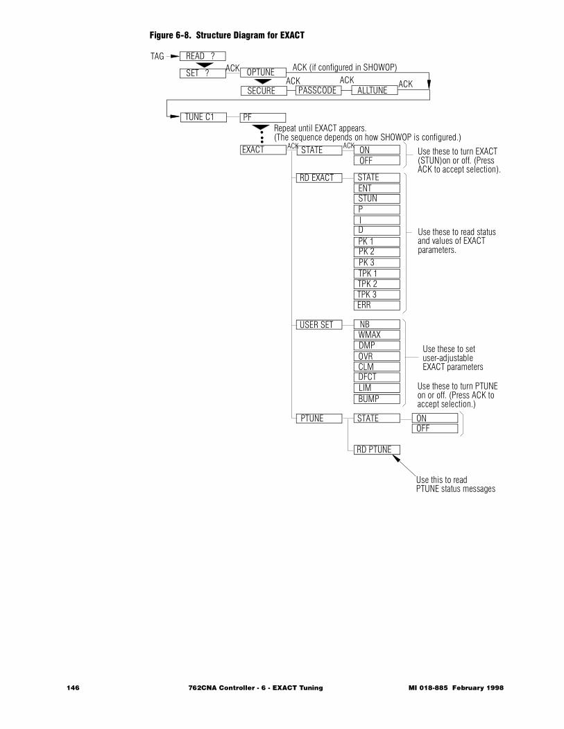
Figure 6-8. Structure Diagram for EXACT
ALLTUNE
TUNE C1
EXACT STATE
RD EXACT
USER SET
PTUNE STATE ONOFF
NBWMAXDMPOVRCLMDFCTLIMBUMP
ONOFF
STATEENTSTUNPIDPK 1PK 2PK 3TPK 1TPK 2TPK 3ERR
Use these to turn EXACT(STUN)on or off. (Press
Use these to read status
Use these to set user-adjustableEXACT parameters
Use these to turn PTUNEon or off. (Press ACK to
SET ?
READ ?TAG
ACK
ACK
RD PTUNE
Use this to readPTUNE status messages
OPTUNEACK ACK
SECURE PASSCODE
ACK (if configured in SHOWOP)
PF
•••
Repeat until EXACT appears.(The sequence depends on how SHOWOP is configured.)
ACK ACK
accept selection.)
ACK to accept selection).
and values of EXACTparameters.
146 762CNA Controller - 6 - EXACT Tuning MI 018-885 February 1998
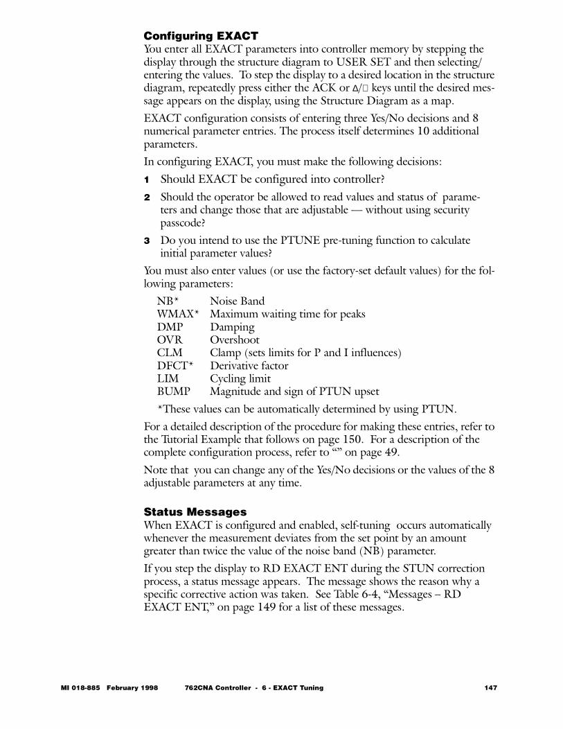
Configuring EXACT You enter all EXACT parameters into controller memory by stepping the display through the structure diagram to USER SET and then selecting/entering the values. To step the display to a desired location in the structure diagram, repeatedly press either the ACK or ∆/∇ keys until the desired mes-sage appears on the display, using the Structure Diagram as a map.EXACT configuration consists of entering three Yes/No decisions and 8 numerical parameter entries. The process itself determines 10 additional parameters.In configuring EXACT, you must make the following decisions: 1 Should EXACT be configured into controller?2 Should the operator be allowed to read values and status of parame-
ters and change those that are adjustable — without using security passcode?
3 Do you intend to use the PTUNE pre-tuning function to calculate initial parameter values?
You must also enter values (or use the factory-set default values) for the fol-lowing parameters:
NB* Noise BandWMAX* Maximum waiting time for peaksDMP Damping OVR Overshoot CLM Clamp (sets limits for P and I influences)DFCT* Derivative factorLIM Cycling limitBUMP Magnitude and sign of PTUN upset*These values can be automatically determined by using PTUN.
For a detailed description of the procedure for making these entries, refer to the Tutorial Example that follows on page 150. For a description of the complete configuration process, refer to “” on page 49. Note that you can change any of the Yes/No decisions or the values of the 8 adjustable parameters at any time.
Status MessagesWhen EXACT is configured and enabled, self-tuning occurs automatically whenever the measurement deviates from the set point by an amount greater than twice the value of the noise band (NB) parameter.If you step the display to RD EXACT ENT during the STUN correction process, a status message appears. The message shows the reason why a specific corrective action was taken. See Table 6-4, “Messages – RD EXACT ENT,” on page 149 for a list of these messages.
MI 018-885 February 1998 762CNA Controller - 6 - EXACT Tuning 147
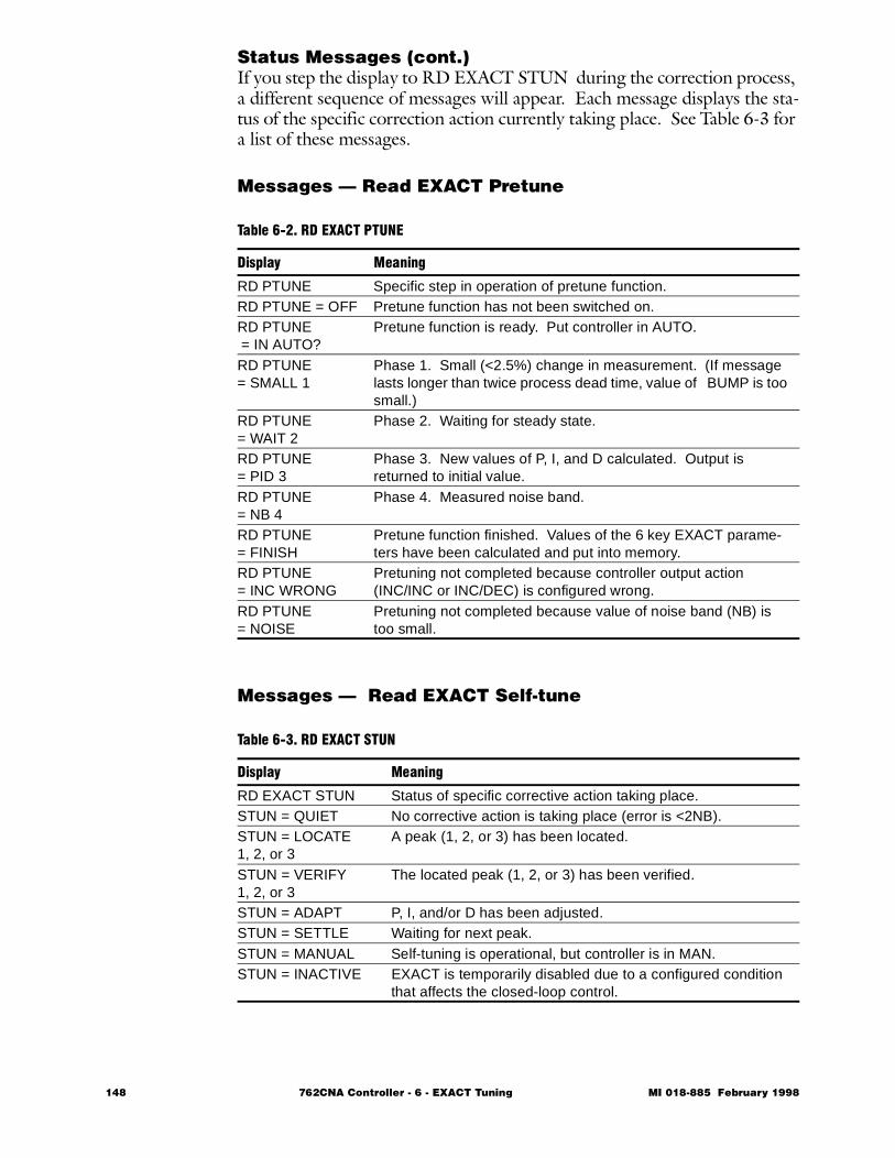
Status Messages (cont.)If you step the display to RD EXACT STUN during the correction process, a different sequence of messages will appear. Each message displays the sta-tus of the specific correction action currently taking place. See Table 6-3 for a list of these messages.
Messages — Read EXACT Pretune
Messages — Read EXACT Self-tune
Table 6-2. RD EXACT PTUNE
Display Meaning
RD PTUNE Specific step in operation of pretune function.RD PTUNE = OFF Pretune function has not been switched on.RD PTUNE = IN AUTO?
Pretune function is ready. Put controller in AUTO.
RD PTUNE= SMALL 1
Phase 1. Small (<2.5%) change in measurement. (If message lasts longer than twice process dead time, value of BUMP is too small.)
RD PTUNE= WAIT 2
Phase 2. Waiting for steady state.
RD PTUNE= PID 3
Phase 3. New values of P, I, and D calculated. Output is returned to initial value.
RD PTUNE= NB 4
Phase 4. Measured noise band.
RD PTUNE= FINISH
Pretune function finished. Values of the 6 key EXACT parame-ters have been calculated and put into memory.
RD PTUNE= INC WRONG
Pretuning not completed because controller output action (INC/INC or INC/DEC) is configured wrong.
RD PTUNE= NOISE
Pretuning not completed because value of noise band (NB) is too small.
Table 6-3. RD EXACT STUN
Display Meaning
RD EXACT STUN Status of specific corrective action taking place.STUN = QUIET No corrective action is taking place (error is <2NB).STUN = LOCATE1, 2, or 3
A peak (1, 2, or 3) has been located.
STUN = VERIFY1, 2, or 3
The located peak (1, 2, or 3) has been verified.
STUN = ADAPT P, I, and/or D has been adjusted.STUN = SETTLE Waiting for next peak.STUN = MANUAL Self-tuning is operational, but controller is in MAN.STUN = INACTIVE EXACT is temporarily disabled due to a configured condition
that affects the closed-loop control.
148 762CNA Controller - 6 - EXACT Tuning MI 018-885 February 1998
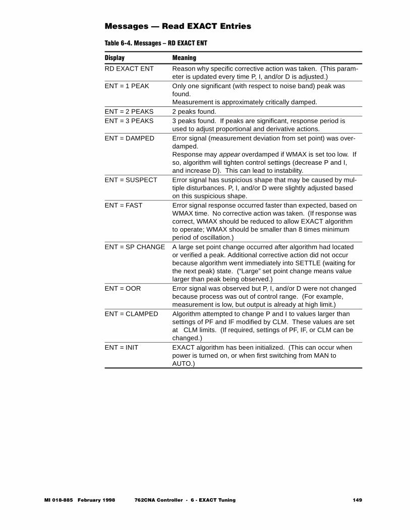
Messages — Read EXACT Entries
Table 6-4. Messages – RD EXACT ENT
Display Meaning
RD EXACT ENT Reason why specific corrective action was taken. (This param-eter is updated every time P, I, and/or D is adjusted.)
ENT = 1 PEAK Only one significant (with respect to noise band) peak was found. Measurement is approximately critically damped.
ENT = 2 PEAKS 2 peaks found.ENT = 3 PEAKS 3 peaks found. If peaks are significant, response period is
used to adjust proportional and derivative actions.ENT = DAMPED Error signal (measurement deviation from set point) was over-
damped.Response may appear overdamped if WMAX is set too low. If so, algorithm will tighten control settings (decrease P and I, and increase D). This can lead to instability.
ENT = SUSPECT Error signal has suspicious shape that may be caused by mul-tiple disturbances. P, I, and/or D were slightly adjusted based on this suspicious shape.
ENT = FAST Error signal response occurred faster than expected, based on WMAX time. No corrective action was taken. (If response was correct, WMAX should be reduced to allow EXACT algorithm to operate; WMAX should be smaller than 8 times minimum period of oscillation.)
ENT = SP CHANGE A large set point change occurred after algorithm had located or verified a peak. Additional corrective action did not occur because algorithm went immediately into SETTLE (waiting for the next peak) state. (“Large” set point change means value larger than peak being observed.)
ENT = OOR Error signal was observed but P, I, and/or D were not changed because process was out of control range. (For example, measurement is low, but output is already at high limit.)
ENT = CLAMPED Algorithm attempted to change P and I to values larger than settings of PF and IF modified by CLM. These values are set at CLM limits. (If required, settings of PF, IF, or CLM can be changed.)
ENT = INIT EXACT algorithm has been initialized. (This can occur when power is turned on, or when first switching from MAN to AUTO.)
MI 018-885 February 1998 762CNA Controller - 6 - EXACT Tuning 149
Tutorial ExampleThe following example describes the procedure for setting up and using EXACT tuning for achieving optimal control of a process loop. Before start-ing, you should decide the following:1 Do you want to use PTUN to generate initial parameter values?2 If not, do you want to use factory default values for all parameters or
do you want to enter your own values? If you want to enter your own values, please have them ready to enter when requested.
A flow chart of the functional steps in the procedure is illustrated in Figure 6-9. The detailed steps of the procedure follow the general flow diagram.
150 762CNA Controller - 6 - EXACT Tuning MI 018-885 February 1998
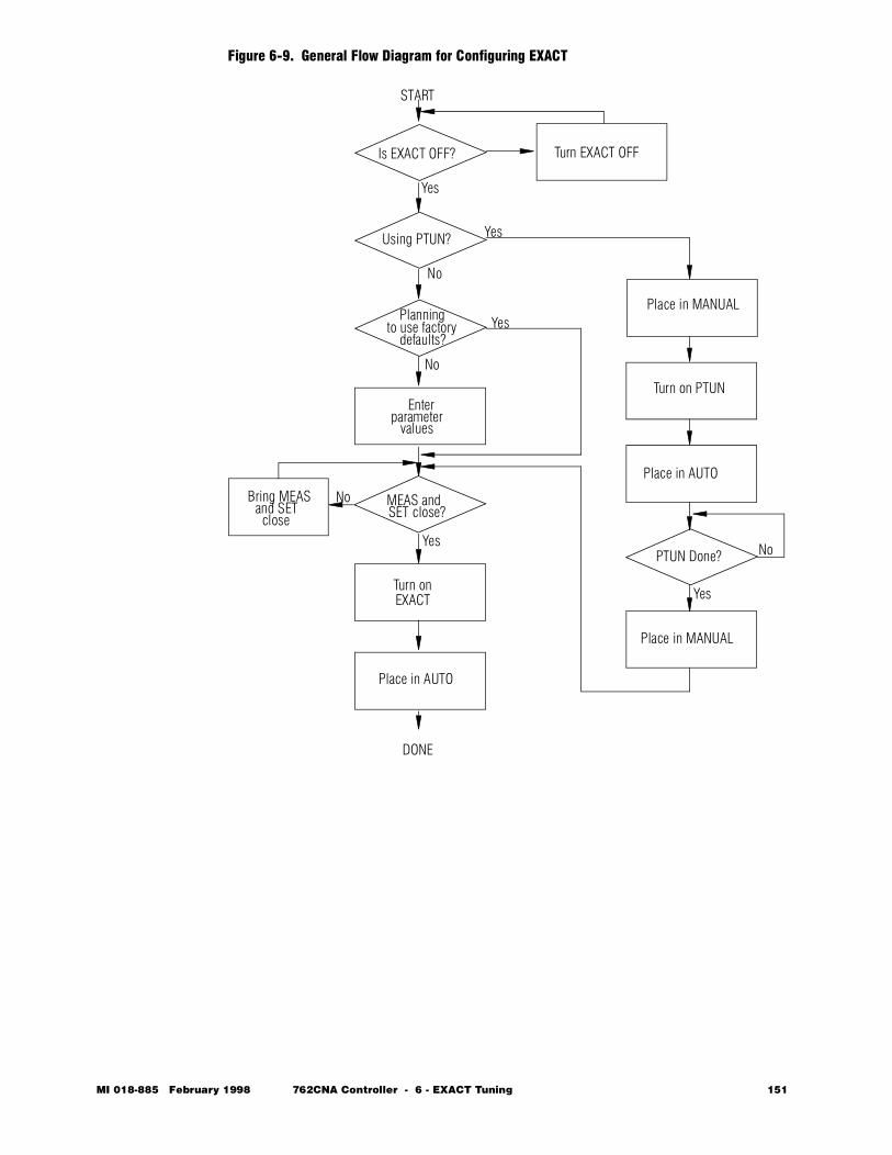
Figure 6-9. General Flow Diagram for Configuring EXACT
START
Is EXACT OFF? Turn EXACT OFF
Using PTUN? Yes
No
Yes
Planningto use factory
defaults?Yes
Enterparameter
values
MEAS andSET close?
Bring MEASand SETclose
Turn onEXACT
Place in AUTO
DONE
Place in MANUAL
Turn on PTUN
Place in AUTO
PTUN Done?
Place in MANUAL
No
No
YesNo
Yes
MI 018-885 February 1998 762CNA Controller - 6 - EXACT Tuning 151
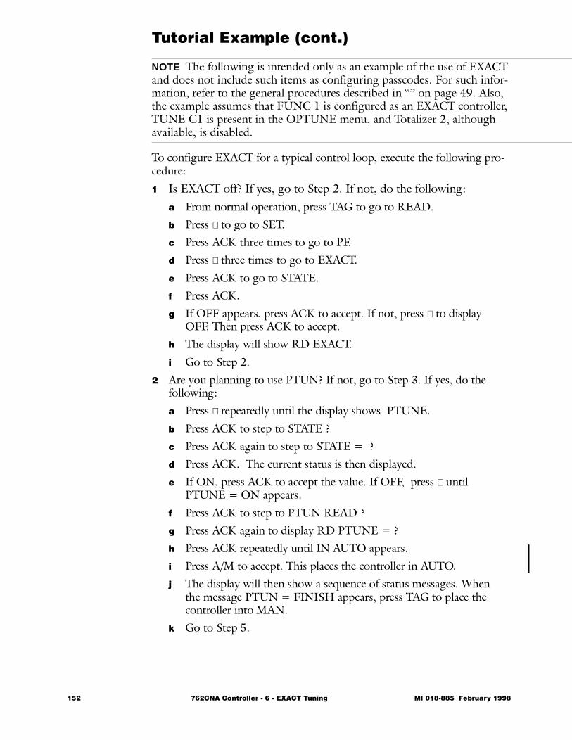
Tutorial Example (cont.)
NOTE The following is intended only as an example of the use of EXACT and does not include such items as configuring passcodes. For such infor-mation, refer to the general procedures described in “” on page 49. Also, the example assumes that FUNC 1 is configured as an EXACT controller, TUNE C1 is present in the OPTUNE menu, and Totalizer 2, although available, is disabled.
To configure EXACT for a typical control loop, execute the following pro-cedure:1 Is EXACT off? If yes, go to Step 2. If not, do the following:
a From normal operation, press TAG to go to READ.b Press ∇ to go to SET.c Press ACK three times to go to PF.d Press ∇ three times to go to EXACT.e Press ACK to go to STATE.f Press ACK. g If OFF appears, press ACK to accept. If not, press ∇ to display
OFF. Then press ACK to accept.h The display will show RD EXACT.i Go to Step 2.
2 Are you planning to use PTUN? If not, go to Step 3. If yes, do the following:a Press ∇ repeatedly until the display shows PTUNE.b Press ACK to step to STATE ?c Press ACK again to step to STATE = ?d Press ACK. The current status is then displayed. e If ON, press ACK to accept the value. If OFF, press ∇ until
PTUNE = ON appears.f Press ACK to step to PTUN READ ?g Press ACK again to display RD PTUNE = ?h Press ACK repeatedly until IN AUTO appears.i Press A/M to accept. This places the controller in AUTO.j The display will then show a sequence of status messages. When
the message PTUN = FINISH appears, press TAG to place the controller into MAN.
k Go to Step 5.
152 762CNA Controller - 6 - EXACT Tuning MI 018-885 February 1998
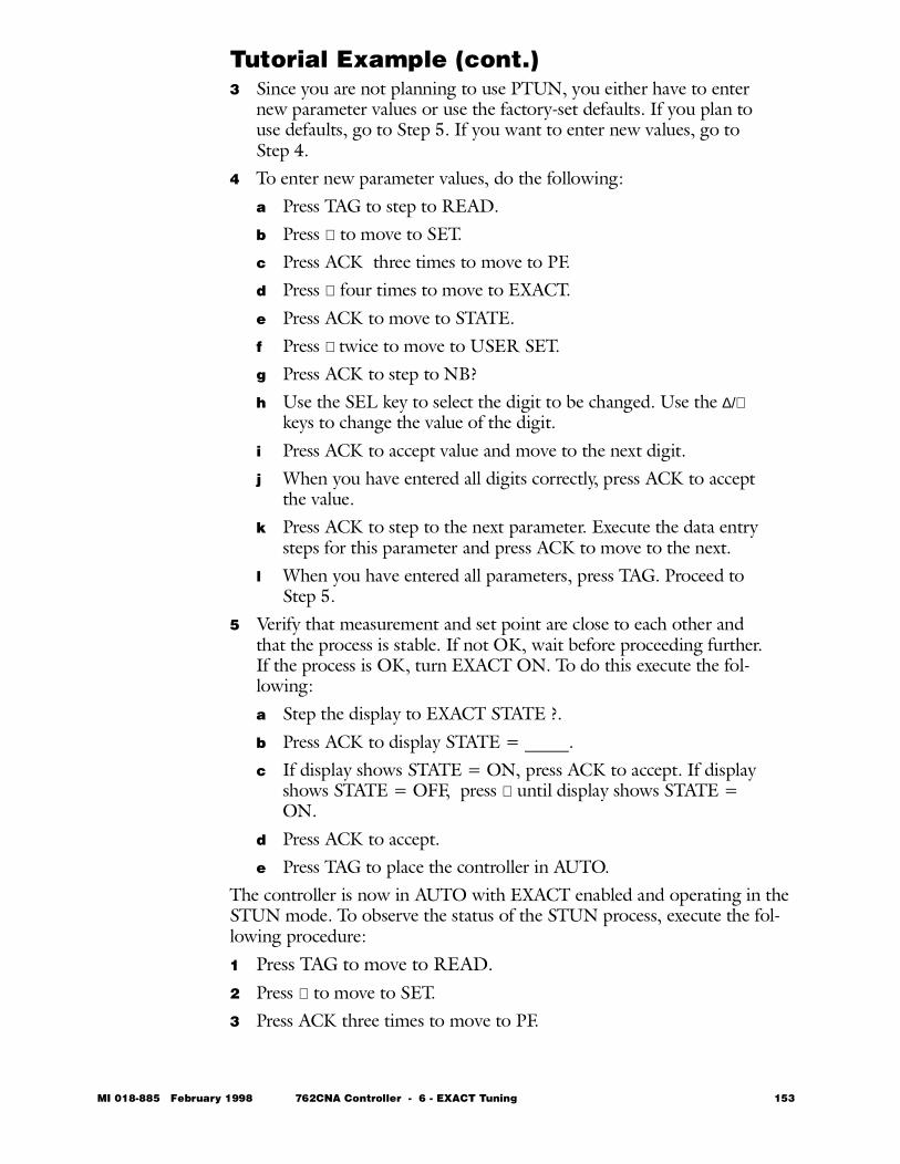
Tutorial Example (cont.)3 Since you are not planning to use PTUN, you either have to enter
new parameter values or use the factory-set defaults. If you plan to use defaults, go to Step 5. If you want to enter new values, go to Step 4.
4 To enter new parameter values, do the following: a Press TAG to step to READ.b Press ∇ to move to SET.c Press ACK three times to move to PF.d Press ∇ four times to move to EXACT.e Press ACK to move to STATE.f Press ∇ twice to move to USER SET.g Press ACK to step to NB?h Use the SEL key to select the digit to be changed. Use the ∆/∇
keys to change the value of the digit. i Press ACK to accept value and move to the next digit.j When you have entered all digits correctly, press ACK to accept
the value.k Press ACK to step to the next parameter. Execute the data entry
steps for this parameter and press ACK to move to the next.l When you have entered all parameters, press TAG. Proceed to
Step 5.5 Verify that measurement and set point are close to each other and
that the process is stable. If not OK, wait before proceeding further. If the process is OK, turn EXACT ON. To do this execute the fol-lowing:a Step the display to EXACT STATE ?.b Press ACK to display STATE = _____.c If display shows STATE = ON, press ACK to accept. If display
shows STATE = OFF, press ∇ until display shows STATE = ON.
d Press ACK to accept.e Press TAG to place the controller in AUTO.
The controller is now in AUTO with EXACT enabled and operating in the STUN mode. To observe the status of the STUN process, execute the fol-lowing procedure:1 Press TAG to move to READ.2 Press ∇ to move to SET.3 Press ACK three times to move to PF.
MI 018-885 February 1998 762CNA Controller - 6 - EXACT Tuning 153
Tutorial Example (cont.)4 Press ∇ four times to move to EXACT.5 Press ACK to move to STATE.6 Press ∇ to move to RD EXACT.7 press ACK to move to STATE.8 Press ∇ twice to move to STUN.9 Press ACK to display the current step (one of the messages shown in
Table 6-3).When the calculation process is complete, press TAG to return.
154 762CNA Controller - 6 - EXACT Tuning MI 018-885 February 1998
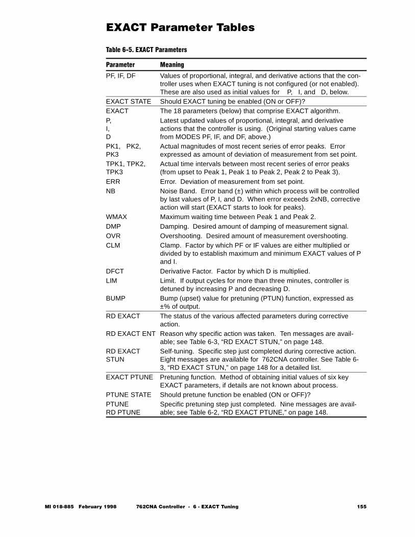
EXACT Parameter Tables Table 6-5. EXACT Parameters
Parameter Meaning
PF, IF, DF Values of proportional, integral, and derivative actions that the con-troller uses when EXACT tuning is not configured (or not enabled). These are also used as initial values for P, I, and D, below.
EXACT STATE Should EXACT tuning be enabled (ON or OFF)?EXACT The 18 parameters (below) that comprise EXACT algorithm.P, I, D
Latest updated values of proportional, integral, and derivative actions that the controller is using. (Original starting values came from MODES PF, IF, and DF, above.)
PK1, PK2, PK3
Actual magnitudes of most recent series of error peaks. Error expressed as amount of deviation of measurement from set point.
TPK1, TPK2, TPK3
Actual time intervals between most recent series of error peaks (from upset to Peak 1, Peak 1 to Peak 2, Peak 2 to Peak 3).
ERR Error. Deviation of measurement from set point.NB Noise Band. Error band (±) within which process will be controlled
by last values of P, I, and D. When error exceeds 2xNB, corrective action will start (EXACT starts to look for peaks).
WMAX Maximum waiting time between Peak 1 and Peak 2.DMP Damping. Desired amount of damping of measurement signal.OVR Overshooting. Desired amount of measurement overshooting.CLM Clamp. Factor by which PF or IF values are either multiplied or
divided by to establish maximum and minimum EXACT values of P and I.
DFCT Derivative Factor. Factor by which D is multiplied.LIM Limit. If output cycles for more than three minutes, controller is
detuned by increasing P and decreasing D.BUMP Bump (upset) value for pretuning (PTUN) function, expressed as
±% of output.RD EXACT The status of the various affected parameters during corrective
action.RD EXACT ENT Reason why specific action was taken. Ten messages are avail-
able; see Table 6-3, “RD EXACT STUN,” on page 148.RD EXACT STUN
Self-tuning. Specific step just completed during corrective action. Eight messages are available for 762CNA controller. See Table 6-3, “RD EXACT STUN,” on page 148 for a detailed list.
EXACT PTUNE Pretuning function. Method of obtaining initial values of six key EXACT parameters, if details are not known about process.
PTUNE STATE Should pretune function be enabled (ON or OFF)?PTUNERD PTUNE
Specific pretuning step just completed. Nine messages are avail-able; see Table 6-2, “RD EXACT PTUNE,” on page 148.
MI 018-885 February 1998 762CNA Controller - 6 - EXACT Tuning 155

Parameter Limits and Values
* After EXACT is configured, specify the parameters listed above. These parameters can also be specified in OPTUNE if the controller is so configured.
** Starting values of P, I, and D are same as PF, IF, and DF (at top of table). EXACT will then continually update these values.
*** PTUN STATE is normally OFF. When you start to use pretune function, you are prompted to turn it ON. After func-tion is completed, it automatically resets to OFF.
Table 6-6. EXACT Parameter Limits and Values
Parameter*
Parameter Limits
Default ValueUser ConfigurationMin Max
PF 1% 8000% 200%IF 0.01 min/rep 200 min/rep 2.00 min/repDF 0 min 100 min 0.0 minEXACTEXACT STATE ON OFF OFFEXACT P 1% 8000% ** ↑
| |
Values are determinedby process
| | | |↓
I 0.01 200 min **D 0 100 min **PK1 –102% +102%PK2 –102% +102%PK3 –102% +102%TPK1 <WMAXTPK2 WMAXTPK3 >WMAXERR –102% +102%NB 0.5% 30%WMAX 0.5 min 200 min 5 minutesDMP 0.1 1 0.2OVR 0 1 0.5CLM 1.25 100 10DFCT 0 4 1LIM 2% 80% 80%BUMP -50% +50% 8%RD EXACT RD EXACT ENT (10 messages) INIT (No Entry)RD EXACT STUN (11 messages) MANUAL (No Entry)EXACT PTUNEPTUNE STATEPTUNE RD PTUNE
ON or OFF (9 Messages)
OFF OFF
OFF***(No Entry)
156 762CNA Controller - 6 - EXACT Tuning MI 018-885 February 1998

762C SINGLESTATION
MICROController
February 1998
Preface • xiii Chapter 1 Quick Check • 1 Chapter 2 Product Overview • 11 Chapter 3 Installation • 23 Chapter 4 Configuration • 49 Chapter 5 Operation • 109 Chapter 6 EXACT Tuning • 135
Ð Chapter 7 Calibration, Troubleshooting, Maintenance • 159
Appendix A Specifications • 183 Appendix B Configuration Worksheets • 193 Appendix C Structure Diagrams • 237 Appendix D Parts List • 247 Appendix E Dimensional Print • 255 Appendix F Functional Diagram • 261 Glossary • 267 Index • 287
The Intelligent Automation People

158 762CNA Controller MI 018-885 February 1998

MI 018-885 Februar
7 Calibration, Troubleshooting, Maintenance
This chapter is divided into the following major sections: • Calibration • 160 • Troubleshooting • 173 • Maintenance • 176
y 1998 762CNA Controller - 7 - Calibration, Troubleshooting, Maintenance 159
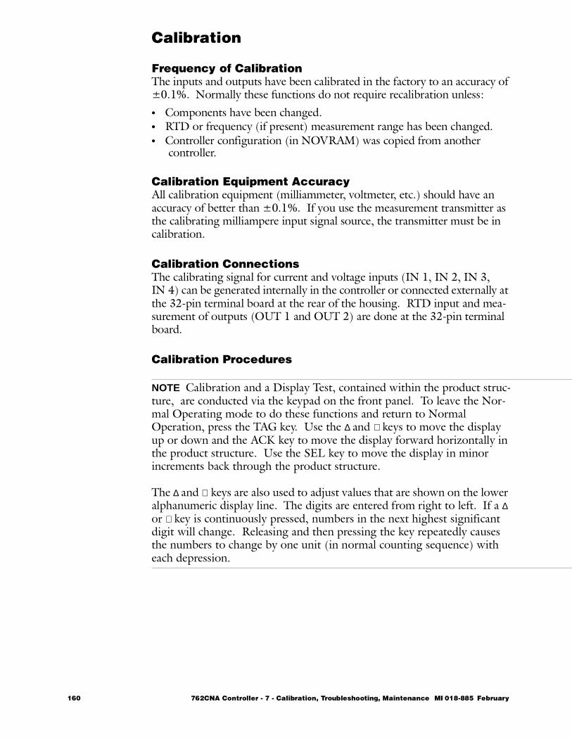
Calibration
Frequency of CalibrationThe inputs and outputs have been calibrated in the factory to an accuracy of ±0.1%. Normally these functions do not require recalibration unless:• Components have been changed.• RTD or frequency (if present) measurement range has been changed.• Controller configuration (in NOVRAM) was copied from another
controller.
Calibration Equipment AccuracyAll calibration equipment (milliammeter, voltmeter, etc.) should have an accuracy of better than ±0.1%. If you use the measurement transmitter as the calibrating milliampere input signal source, the transmitter must be in calibration.
Calibration ConnectionsThe calibrating signal for current and voltage inputs (IN 1, IN 2, IN 3, IN 4) can be generated internally in the controller or connected externally at the 32-pin terminal board at the rear of the housing. RTD input and mea-surement of outputs (OUT 1 and OUT 2) are done at the 32-pin terminal board.
Calibration Procedures
NOTE Calibration and a Display Test, contained within the product struc-ture, are conducted via the keypad on the front panel. To leave the Nor-mal Operating mode to do these functions and return to Normal Operation, press the TAG key. Use the ∆ and ∇ keys to move the display up or down and the ACK key to move the display forward horizontally in the product structure. Use the SEL key to move the display in minor increments back through the product structure.
The ∆ and ∇ keys are also used to adjust values that are shown on the lower alphanumeric display line. The digits are entered from right to left. If a ∆ or ∇ key is continuously pressed, numbers in the next highest significant digit will change. Releasing and then pressing the key repeatedly causes the numbers to change by one unit (in normal counting sequence) with each depression.
160 762CNA Controller - 7 - Calibration, Troubleshooting, Maintenance MI 018-885 February
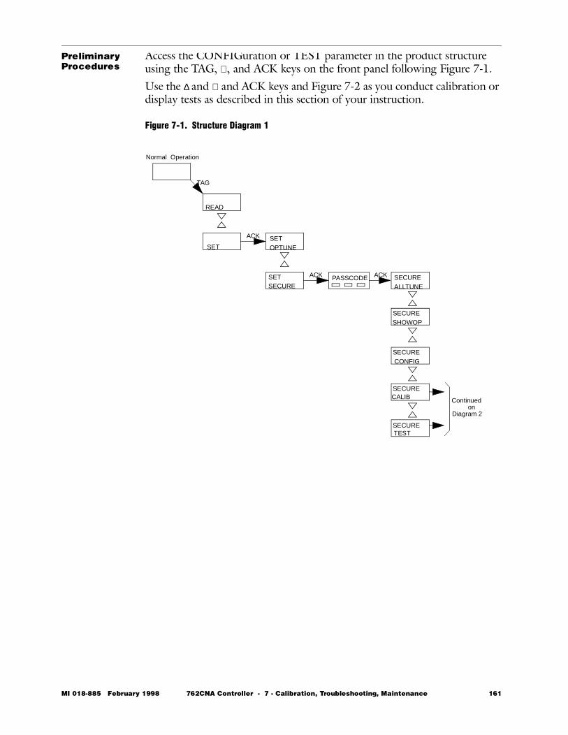
Preliminary Procedures
Access the CONFIGuration or TEST parameter in the product structure using the TAG, ∇, and ACK keys on the front panel following Figure 7-1.Use the ∆ and ∇ and ACK keys and Figure 7-2 as you conduct calibration or display tests as described in this section of your instruction.
Figure 7-1. Structure Diagram 1
Normal Operation
ACKACK
ACK
TAG
READ
SETSETOPTUNE
SETSECURE
PASSCODE SECUREALLTUNE
SECURESHOWOP
SECURECONFIG
SECURECALIB
SECURETEST
Continuedon
Diagram 2
MI 018-885 February 1998 762CNA Controller - 7 - Calibration, Troubleshooting, Maintenance 161
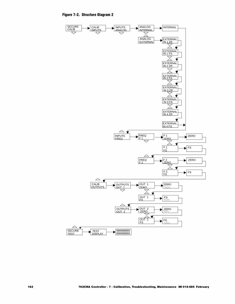
Figure 7-2. Structure Diagram 2
SECURECALIB
CALIBINPUTS
INPUTSANALOG
ANALOGINTERNAL
INTERNAL
ANALOGEXTERNAL
EXTERNAL
EXTERNAL
EXTERNAL
EXTERNAL
EXTERNAL
EXTERNAL
EXTERNAL
EXTERNAL
IN 1 ZR
IN 1 FS
IN 2 ZR
IN 2 FS
IN 3 ZR
IN 3 FS
IN 4 ZR
IN 4 FS
INPUTSFREQ
FREQF 1
FREQF 2
F 1ZERO
F 1FS
F 2
F 2
ZERO
FS
ZERO
FS
ZERO
FS
CALIBOUTPUTS
OUTPUTSOUT 1
OUTPUTSOUT 2
OUT 1ZERO
OUT 1FS
OUT 2
OUT 2
ZERO
FS
ZERO
FS
ZERO
FS
SECURETEST
TESTDISPLAY 888888888
888888888
162 762CNA Controller - 7 - Calibration, Troubleshooting, Maintenance MI 018-885 February
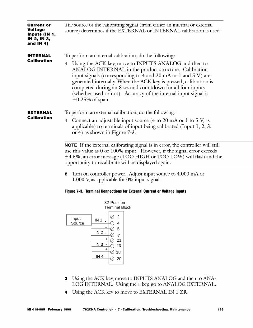
Current or Voltage Inputs (IN 1, IN 2, IN 3, and IN 4)
The source of the calibrating signal (from either an internal or external source) determines if the EXTERNAL or INTERNAL calibration is used.
INTERNAL Calibration
To perform an internal calibration, do the following:1 Using the ACK key, move to INPUTS ANALOG and then to
ANALOG INTERNAL in the product structure. Calibration input signals (corresponding to 4 and 20 mA or 1 and 5 V) are generated internally. When the ACK key is pressed, calibration is completed during an 8-second countdown for all four inputs (whether used or not). Accuracy of the internal input signal is ±0.25% of span.
EXTERNAL Calibration
To perform an external calibration, do the following:
1 Connect an adjustable input source (4 to 20 mA or 1 to 5 V, as applicable) to terminals of input being calibrated (Input 1, 2, 3, or 4) as shown in Figure 7-3.
NOTE If the external calibrating signal is in error, the controller will still use this value as 0 or 100% input. However, if the signal error exceeds ±4.5%, an error message (TOO HIGH or TOO LOW) will flash and the opportunity to recalibrate will be displayed again.
2 Turn on controller power. Adjust input source to 4.000 mA or 1.000 V, as applicable for 0% input signal.
Figure 7-3. Terminal Connections for External Current or Voltage Inputs
3 Using the ACK key, move to INPUTS ANALOG and then to ANA-LOG INTERNAL. Using the ∇ key, go to ANALOG EXTERNAL.
4 Using the ACK key to move to EXTERNAL IN 1 ZR.
Input Source
IN 1
IN 2
IN 3
IN 4
+
+
+
+
-
-
-
-
2
45
72123
18
20
32-PositionTerminal Block
MI 018-885 February 1998 762CNA Controller - 7 - Calibration, Troubleshooting, Maintenance 163
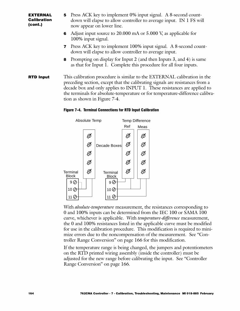
EXTERNAL Calibration(cont.)
5 Press ACK key to implement 0% input signal. A 8-second count-down will elapse to allow controller to average input. IN 1 FS will now appear on lower line.
6 Adjust input source to 20.000 mA or 5.000 V, as applicable for 100% input signal.
7 Press ACK key to implement 100% input signal. A 8-second count-down will elapse to allow controller to average input.
8 Prompting on display for Input 2 (and then Inputs 3, and 4) is same as that for Input 1. Complete this procedure for all four inputs.
RTD Input This calibration procedure is similar to the EXTERNAL calibration in the preceding section, except that the calibrating signals are resistances from a decade box and only applies to INPUT 1. These resistances are applied to the terminals for absolute-temperature or for temperature-difference calibra-tion as shown in Figure 7-4.
Figure 7-4. Terminal Connections for RTD Input Calibration
With absolute-temperature measurement, the resistances corresponding to 0 and 100% inputs can be determined from the IEC 100 or SAMA 100 curve, whichever is applicable. With temperature-difference measurement, the 0 and 100% resistances listed in the applicable curve must be modified for use in the calibration procedure. This modification is required to mini-mize errors due to the noncompensation of the measurement. See “Con-troller Range Conversion” on page 166 for this modification.If the temperature range is being changed, the jumpers and potentiometers on the RTD printed wiring assembly (inside the controller) must be adjusted for the new range before calibrating the input. See “Controller Range Conversion” on page 166.
Ref Meas
9
10
11
9
10
11
Decade Boxes
TerminalBlock
TerminalBlock
Absolute Temp Temp Difference
164 762CNA Controller - 7 - Calibration, Troubleshooting, Maintenance MI 018-885 February
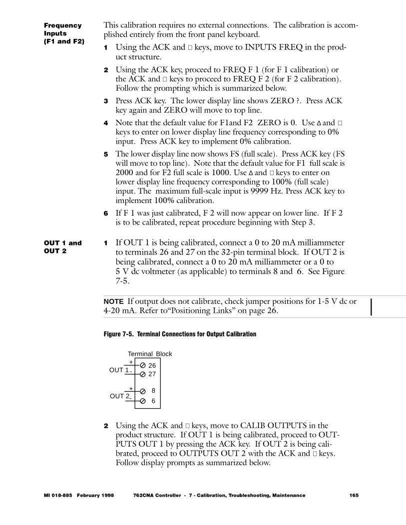
Frequency Inputs (F1 and F2)
This calibration requires no external connections. The calibration is accom-plished entirely from the front panel keyboard.1 Using the ACK and ∇ keys, move to INPUTS FREQ in the prod-
uct structure.2 Using the ACK key, proceed to FREQ F 1 (for F 1 calibration) or
the ACK and ∇ keys to proceed to FREQ F 2 (for F 2 calibration). Follow the prompting which is summarized below.
3 Press ACK key. The lower display line shows ZERO ?. Press ACK key again and ZERO will move to top line.
4 Note that the default value for F1and F2 ZERO is 0. Use ∆ and ∇ keys to enter on lower display line frequency corresponding to 0% input. Press ACK key to implement 0% calibration.
5 The lower display line now shows FS (full scale). Press ACK key (FS will move to top line). Note that the default value for F1 full scale is 2000 and for F2 full scale is 1000. Use ∆ and ∇ keys to enter on lower display line frequency corresponding to 100% (full scale) input. The maximum full-scale input is 9999 Hz. Press ACK key to implement 100% calibration.
6 If F 1 was just calibrated, F 2 will now appear on lower line. If F 2 is to be calibrated, repeat procedure beginning with Step 3.
OUT 1 and OUT 2
1 If OUT 1 is being calibrated, connect a 0 to 20 mA milliammeter to terminals 26 and 27 on the 32-pin terminal block. If OUT 2 is being calibrated, connect a 0 to 20 mA milliammeter or a 0 to 5 V dc voltmeter (as applicable) to terminals 8 and 6. See Figure 7-5.
NOTE If output does not calibrate, check jumper positions for 1-5 V dc or 4-20 mA. Refer to“Positioning Links” on page 26.
Figure 7-5. Terminal Connections for Output Calibration
2 Using the ACK and ∇ keys, move to CALIB OUTPUTS in the product structure. If OUT 1 is being calibrated, proceed to OUT-PUTS OUT 1 by pressing the ACK key. If OUT 2 is being cali-brated, proceed to OUTPUTS OUT 2 with the ACK and ∇ keys. Follow display prompts as summarized below.
2627
8
6OUT 2
OUT 1
Terminal+-
+
-
Block
MI 018-885 February 1998 762CNA Controller - 7 - Calibration, Troubleshooting, Maintenance 165
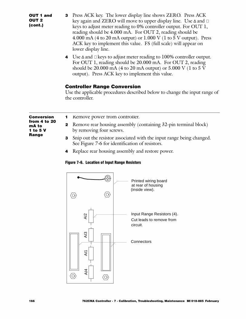
OUT 1 and OUT 2 (cont.)
3 Press ACK key. The lower display line shows ZERO. Press ACK key again and ZERO will move to upper display line. Use ∆ and ∇ keys to adjust meter reading to 0% controller output. For OUT 1, reading should be 4.000 mA. For OUT 2, reading should be 4.000 mA (4 to 20 mA output) or 1.000 V (1 to 5 V output). Press ACK key to implement this value. FS (full scale) will appear on lower display line.
4 Use ∆ and ∇ keys to adjust meter reading to 100% controller output. For OUT 1, reading should be 20.000 mA. For OUT 2, reading should be 20.000 mA (4 to 20 mA output) or 5.000 V (1 to 5 V output). Press ACK key to implement this value.
Controller Range ConversionUse the applicable procedures described below to change the input range of the controller.
Conversion from 4 to 20 mA to 1 to 5 V Range
1 Remove power from controller.2 Remove rear housing assembly (containing 32-pin terminal block)
by removing four screws.3 Snip out the resistor associated with the input range being changed.
See Figure 7-6 for identification of resistors.4 Replace rear housing assembly and restore power.
Figure 7-6. Location of Input Range Resistors
AI4
AI1
AI3
AI2 Input Range Resistors (4).
Cut leads to remove fromcircuit.
Connectors
Printed wiring boardat rear of housing(inside view).
166 762CNA Controller - 7 - Calibration, Troubleshooting, Maintenance MI 018-885 February
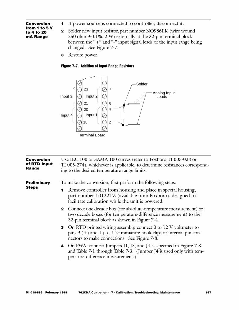
Conversion from 1 to 5 V to 4 to 20 mA Range
1 If power source is connected to controller, disconnect it.2 Solder new input resistor, part number NO986FK (wire wound
250 ohm ±0.1%, 2 W) externally at the 32-pin terminal block between the “+” and “-” input signal leads of the input range being changed. See Figure 7-7.
3 Restore power.
Figure 7-7. Addition of Input Range Resistors
Conversion of RTD Input Range
Use IEC 100 or SAMA 100 curves (refer to Foxboro TI 005-028 or TI 005-274), whichever is applicable, to determine resistances correspond-ing to the desired temperature range limits.
Preliminary Steps
To make the conversion, first perform the following steps:1 Remove controller from housing and place in special housing,
part number L0122TZ (available from Foxboro), designed to facilitate calibration while the unit is powered.
2 Connect one decade box (for absolute-temperature measurement) or two decade boxes (for temperature-difference measurement) to the 32-pin terminal block as shown in Figure 7-4.
3 On RTD printed wiring assembly, connect 0 to 12 V voltmeter to pins 9 (+) and 1 (-). Use miniature hook clips or internal pin con-nectors to make connections. See Figure 7-8.
4 On PWA, connect Jumpers J1, J3, and J4 as specified in Figure 7-8 and Table 7-1 through Table 7-3. (Jumper J4 is used only with tem-perature-difference measurement.)
2
45
7
18
20
21
23
Input 1
Input 2Input 3
Input 4
Analog InputLeads
Solder
Terminal Board
MI 018-885 February 1998 762CNA Controller - 7 - Calibration, Troubleshooting, Maintenance 167
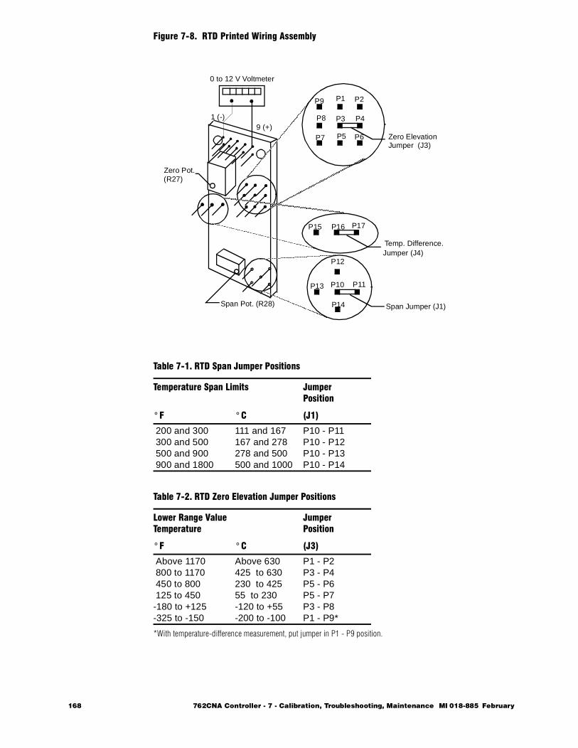
Figure 7-8. RTD Printed Wiring Assembly
*With temperature-difference measurement, put jumper in P1 - P9 position.
Table 7-1. RTD Span Jumper Positions
Temperature Span Limits JumperPosition
° F ° C (J1)
200 and 300 300 and 500 500 and 900 900 and 1800
111 and 167167 and 278278 and 500500 and 1000
P10 - P11P10 - P12P10 - P13P10 - P14
Table 7-2. RTD Zero Elevation Jumper Positions
Lower Range ValueTemperature
JumperPosition
° F ° C (J3)
Above 1170 800 to 1170 450 to 800 125 to 450-180 to +125-325 to -150
Above 630425 to 630230 to 42555 to 230-120 to +55-200 to -100
P1 - P2P3 - P4P5 - P6P5 - P7P3 - P8P1 - P9*
P1 P2
P3 P4
P5 P6P7
P8
P9
P15 P16 P17
P10 P11
P12
P13
P14
1 (-)9 (+)
Zero ElevationJumper (J3)
Temp. Difference.Jumper (J4)
Span Jumper (J1)
0 to 12 V Voltmeter
Span Pot. (R28)
Zero Pot. (R27)
168 762CNA Controller - 7 - Calibration, Troubleshooting, Maintenance MI 018-885 February
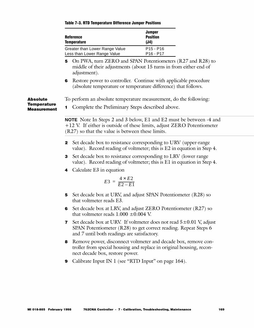
5 On PWA, turn ZERO and SPAN Potentiometers (R27 and R28) to middle of their adjustments (about 15 turns in from either end of adjustment).
6 Restore power to controller. Continue with applicable procedure (absolute temperature or temperature difference) that follows.
Absolute TemperatureMeasurement
To perform an absolute temperature measurement, do the following:
1 Complete the Preliminary Steps described above.
NOTE Note In Steps 2 and 3 below, E1 and E2 must be between -4 and +12 V. If either is outside of these limits, adjust ZERO Potentiometer (R27) so that the value is between these limits.
2 Set decade box to resistance corresponding to URV (upper-range value). Record reading of voltmeter; this is E2 in equation in Step 4.
3 Set decade box to resistance corresponding to LRV (lower range value). Record reading of voltmeter; this is E1 in equation in Step 4.
4 Calculate E3 in equation
5 Set decade box at URV, and adjust SPAN Potentiometer (R28) so that voltmeter reads E3.
6 Set decade box at LRV, and adjust ZERO Potentiometer (R27) so that voltmeter reads 1.000 ±0.004 V.
7 Set decade box at URV. If voltmeter does not read 5±0.01 V, adjust SPAN Potentiometer (R28) to get correct reading. Repeat Steps 6 and 7 until both readings are satisfactory.
8 Remove power, disconnect voltmeter and decade box, remove con-troller from special housing and replace in original housing, recon-nect decade box, restore power.
9 Calibrate Input IN 1 (see “RTD Input” on page 164).
Table 7-3. RTD Temperature Difference Jumper Positions
ReferenceTemperature
JumperPosition(J4)
Greater than Lower Range ValueLess than Lower Range Value
P15 - P16P16 - P17
E34 E2×
E2 E1–--------------------=
MI 018-885 February 1998 762CNA Controller - 7 - Calibration, Troubleshooting, Maintenance 169
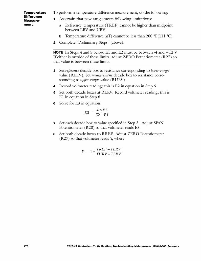
TemperatureDifference Measure-ment
To perform a temperature difference measurement, do the following:
1 Ascertain that new range meets following limitations:a Reference temperature (TREF) cannot be higher than midpoint
between LRV and URV.b Temperature difference (∆T) cannot be less than 200 °F(111 °C).
2 Complete “Preliminary Steps” (above).
NOTE In Steps 4 and 5 below, E1 and E2 must be between -4 and +12 V. If either is outside of these limits, adjust ZERO Potentiometer (R27) so that value is between these limits.
3 Set reference decade box to resistance corresponding to lower-range value (RLRV). Set measurement decade box to resistance corre-sponding to upper-range value (RURV).
4 Record voltmeter reading; this is E2 in equation in Step 6.5 Set both decade boxes at RLRV. Record voltmeter reading; this is
E1 in equation in Step 6.6 Solve for E3 in equation
7 Set each decade box to value specified in Step 3. Adjust SPAN Potentiometer (R28) so that voltmeter reads E3.
8 Set both decade boxes to RREF. Adjust ZERO Potentiometer (R27) so that voltmeter reads Y, where
E34 E2×
E2 E1–--------------------=
Y 1TREF TLRV–TURV TLRV–-------------------------------------+=
170 762CNA Controller - 7 - Calibration, Troubleshooting, Maintenance MI 018-885 February
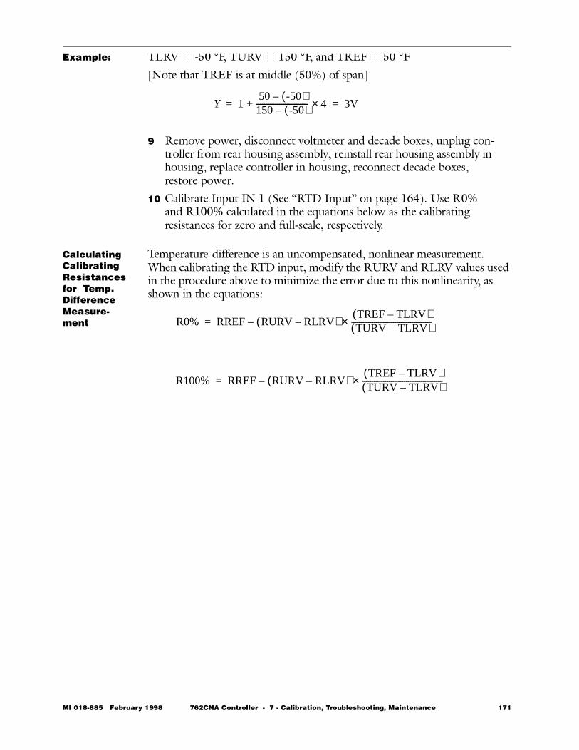
Example: TLRV = -50 °F, TURV = 150 °F, and TREF = 50 °F[Note that TREF is at middle (50%) of span]
9 Remove power, disconnect voltmeter and decade boxes, unplug con-troller from rear housing assembly, reinstall rear housing assembly in housing, replace controller in housing, reconnect decade boxes, restore power.
10 Calibrate Input IN 1 (See “RTD Input” on page 164). Use R0% and R100% calculated in the equations below as the calibrating resistances for zero and full-scale, respectively.
Calculating Calibrating Resistances for Temp. Difference Measure-ment
Temperature-difference is an uncompensated, nonlinear measurement. When calibrating the RTD input, modify the RURV and RLRV values used in the procedure above to minimize the error due to this nonlinearity, as shown in the equations:
Y 150 -50( )–150 -50( )–--------------------------- 4×+ 3V= =
R0% RREF RURV RLRV–( )TREF TLRV–( )TURV TLRV–( )------------------------------------------×–=
R100% RREF RURV RLRV–( )TREF TLRV–( )TURV TLRV–( )------------------------------------------×–=
MI 018-885 February 1998 762CNA Controller - 7 - Calibration, Troubleshooting, Maintenance 171
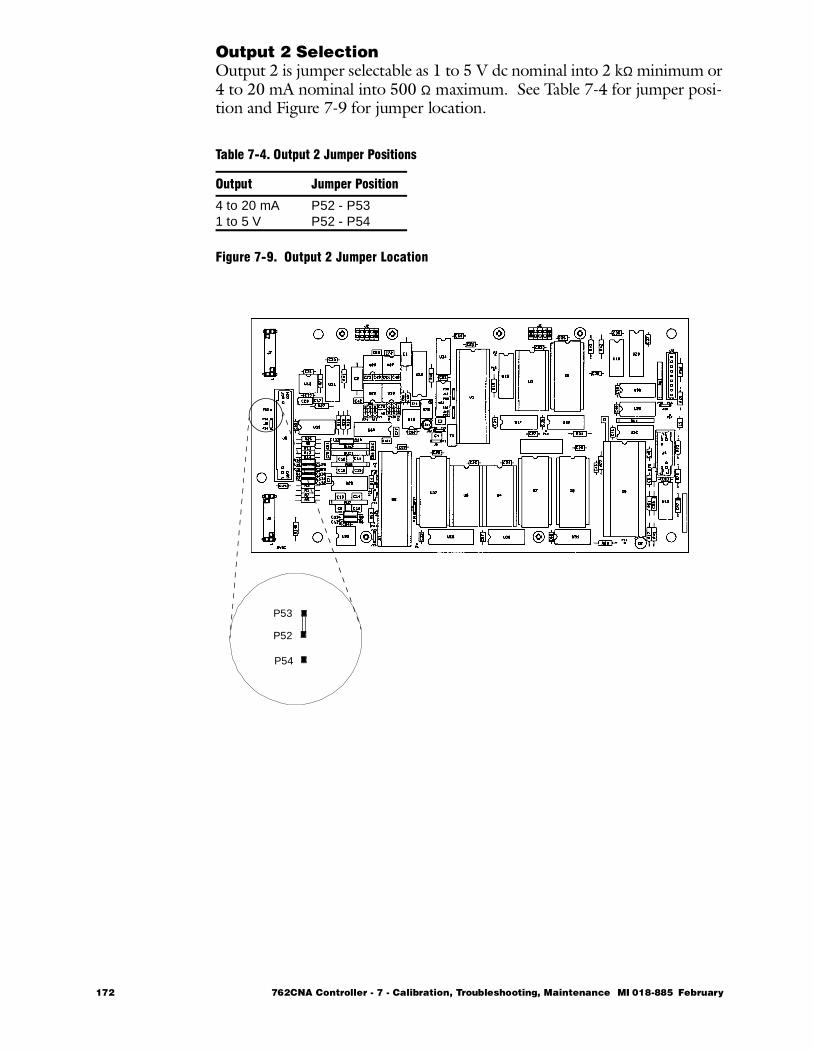
Output 2 SelectionOutput 2 is jumper selectable as 1 to 5 V dc nominal into 2 kΩ minimum or 4 to 20 mA nominal into 500 Ω maximum. See Table 7-4 for jumper posi-tion and Figure 7-9 for jumper location.
Figure 7-9. Output 2 Jumper Location
Table 7-4. Output 2 Jumper Positions
Output Jumper Position
4 to 20 mA1 to 5 V
P52 - P53P52 - P54
P53
P52
P54
172 762CNA Controller - 7 - Calibration, Troubleshooting, Maintenance MI 018-885 February
Troubleshooting
Test Display This TEST checks that all portions of the display can be illuminated. It is accessed by going to SECURE CALIB in the menu structure (SeeFigure 7-1) and pressing the ∇ key. The display will show SECURE TEST. Press the ACK key. The display will change to TEST DISPLAY. Press the ACK key again. If any segment of the display (except the controller fault indicator) is not illuminated, that segment is malfunctioning. Press ACK to return to Normal mode after the test.
Error Messages
Certain problems will generate error messages on the display. These mes-sages are described below:NOVRAM COPY FAIL: Copy function was not successfully executed. Make sure NOVRAMS and copy accessory are properly seated and try again.NOVRAM ALL FAIL*: Memory module failures. Both original (master) and copy failed.NOVRAM MSTR FAIL*: Memory module failure.WRONG NOVRAM*: Memory module is for a 760, 761, or other con-troller or contains corrupt data.*Replace NOVRAM if these errors occur.
Display Problems
Symptom: Display becomes unstable and flashes on and off.Possible Cause: Input voltage may have dropped below minimum level.Symptom: Display goes blank.Possible Cause: Input voltage may have dropped below minimum level.Symptom: Display blank and controller fault indicator flashes.Possible Cause: NOVRAM may not be properly seated or is damaged.
Configur-ation Problems
Compare the actual configuration of the parameter in question against the desired configuration as recorded on the Configuration Worksheet. If the worksheet is not available, place the NOVRAM in another controller. If the problem is present in the second controller, it is most likely a configuration problem. The copy accessory can often be used to save a corrupted NOVRAM. Copy a good NOVRAM onto the corrupted NOVRAM.If the controller oscillates when in automatic, and if the output and mea-surement stop oscillating when placed in manual, the controller may not be tuned properly.If the controller tuning parameters wind up when EXACT is configured and left on, switch EXACT off or the controller to manual and the output to a safe state.
MI 018-885 February 1998 762CNA Controller - 7 - Calibration, Troubleshooting, Maintenance 173
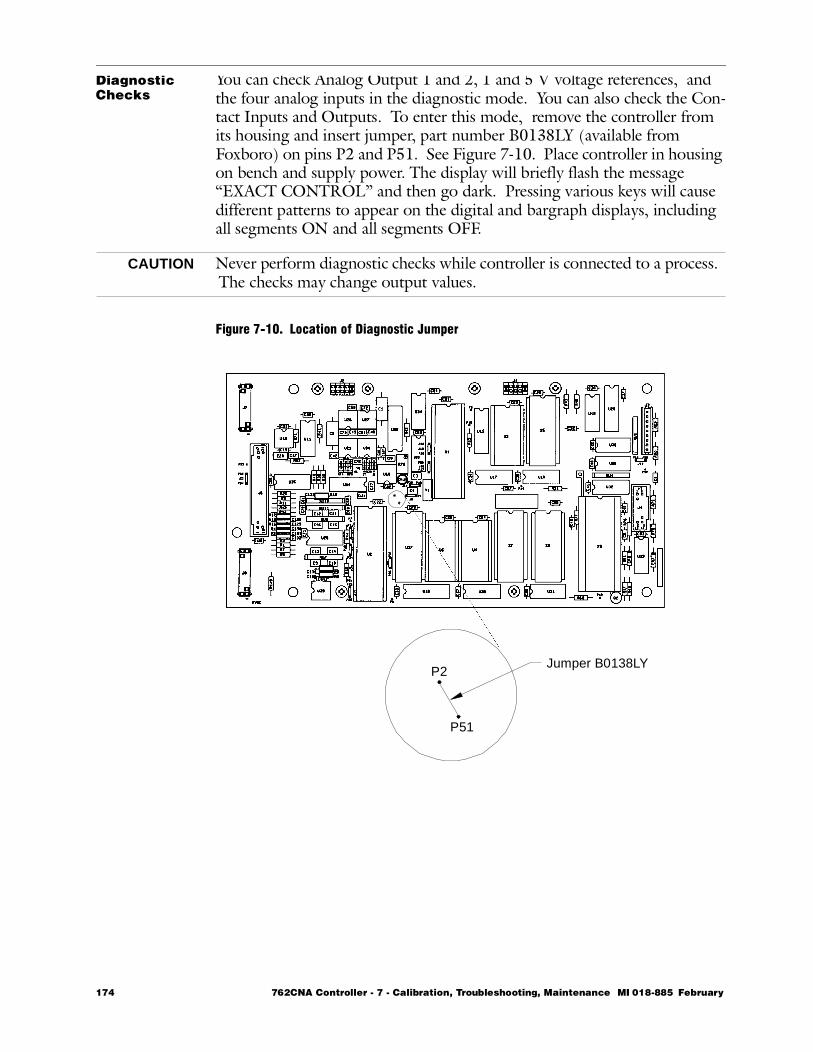
Diagnostic Checks
You can check Analog Output 1 and 2, 1 and 5 V voltage references, and the four analog inputs in the diagnostic mode. You can also check the Con-tact Inputs and Outputs. To enter this mode, remove the controller from its housing and insert jumper, part number B0138LY (available from Foxboro) on pins P2 and P51. See Figure 7-10. Place controller in housing on bench and supply power. The display will briefly flash the message “EXACT CONTROL” and then go dark. Pressing various keys will cause different patterns to appear on the digital and bargraph displays, including all segments ON and all segments OFF.
CAUTION Never perform diagnostic checks while controller is connected to a process. The checks may change output values.
Figure 7-10. Location of Diagnostic Jumper
P2
P51
Jumper B0138LY
174 762CNA Controller - 7 - Calibration, Troubleshooting, Maintenance MI 018-885 February
Diagnostic Checks (cont.)
Now that you are in the diagnostics mode, you can run eight diagnostic checks (one with each of the keys on the front panel). See Table 7-5. Read the current at Output 1 on a milliammeter connected at terminals 26(+) and 27(-) and the current or voltage (depending on the position of the out-put jumper) at Output 2 at terminals 8(+) and 6(-). If the current or volt-age reading does not match the expected value for the parameter being tested, there is a problem. The last four checks require an input. Connect inputs at terminals shown in Figure 7-3.
In the Diagnostic Mode, Contact Inputs are repeated to the Contact Out-puts. Contact Inputs and Outputs are connected at the terminals shown in Table 7-6.
Return to Normal Operating Mode by removing power from your bench housing, removing the diagnostic jumper, and replacing controller into its original housing.
Table 7-5. Diagnostics
Key Tested Parameter
∆ Full Scale(approx. 23 mA or 5.75 V)
∇ Zero (0 mA or 0 V)W/P 5 V Reference
(20 mA or 5 V)SEL 1 V Reference
(4 mA or 0 V)R/L Analog Input 4TAG Analog Input 3A/M Analog Input 1ACK Analog Input 2
Table 7-6. Contact Input and Output Terminals
Signal Terminal
CI 1CommonCI 2
293028
CO 1CommonCO 2
323031
MI 018-885 February 1998 762CNA Controller - 7 - Calibration, Troubleshooting, Maintenance 175
Maintenance
General InformationThe maintenance of the 762CNA Controller is limited to miscellaneous tests and checks, and replacement of the parts listed below. For part num-bers, see Appendix D.• Front panel assembly• NOVRAM and associated three memory chips (ROMs)• Transformer assembly• Rear panel assembly• Display Cable• RTD temperature measurement and output Isolation Boards• Surge Suppressor• Miscellaneous mechanical parts
WARNING This product has many components that have critical safety characteristics. Component substitution may impair the electrical safety of this equipment and its suitability for use in Class I, Division 2 hazardous locations. DO NOT substitute components. Replace components only with identical fac-tory supplied components.
Attempts by the user to repair the printed wiring assemblies could result in damage and voiding of the warranty. The recommended repair procedure is replacement of the printed wiring assembly (PWA) or return of the PWA to the factory for repair.It is recommended that the controller be removed from its housing to a ser-vice bench for replacement of parts.
Removal and Replacement of PartsFigure 7-11 is essentially self-explanatory in showing how parts are removed and reinstalled. Refer to the applicable sections immediately following for additional details.
176 762CNA Controller - 7 - Calibration, Troubleshooting, Maintenance MI 018-885 February
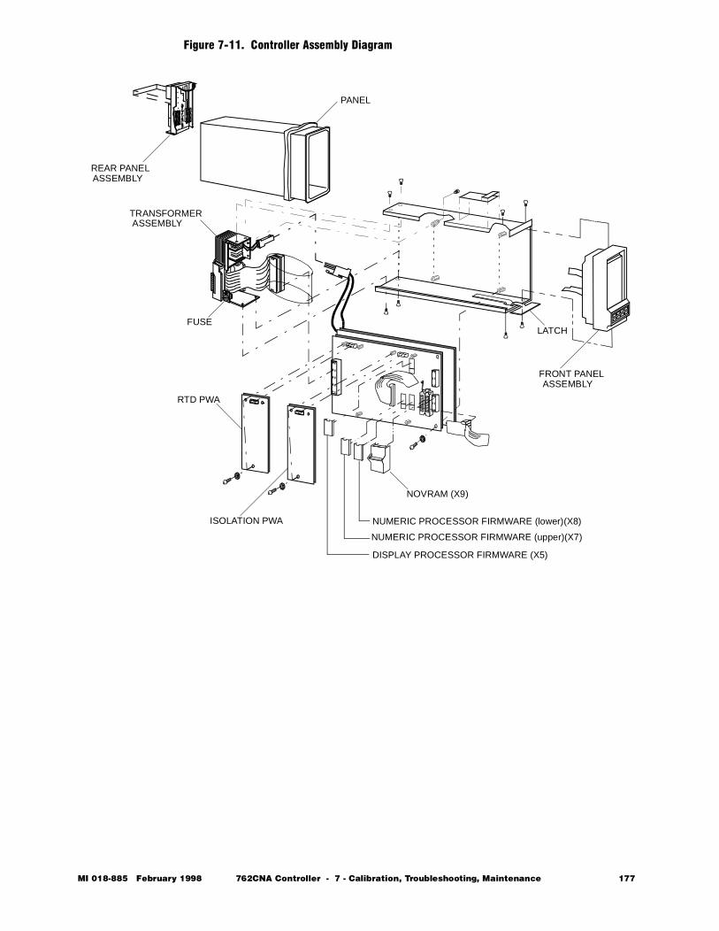
Figure 7-11. Controller Assembly Diagram
. . .
. . .
. . .
. . .
. . .
. . .
REAR PANELASSEMBLY
PANEL
TRANSFORMERASSEMBLY
FUSELATCH
RTD PWA
ISOLATION PWA
NOVRAM (X9)
FRONT PANELASSEMBLY
NUMERIC PROCESSOR FIRMWARE (lower)(X8)
NUMERIC PROCESSOR FIRMWARE (upper)(X7)
DISPLAY PROCESSOR FIRMWARE (X5)
MI 018-885 February 1998 762CNA Controller - 7 - Calibration, Troubleshooting, Maintenance 177
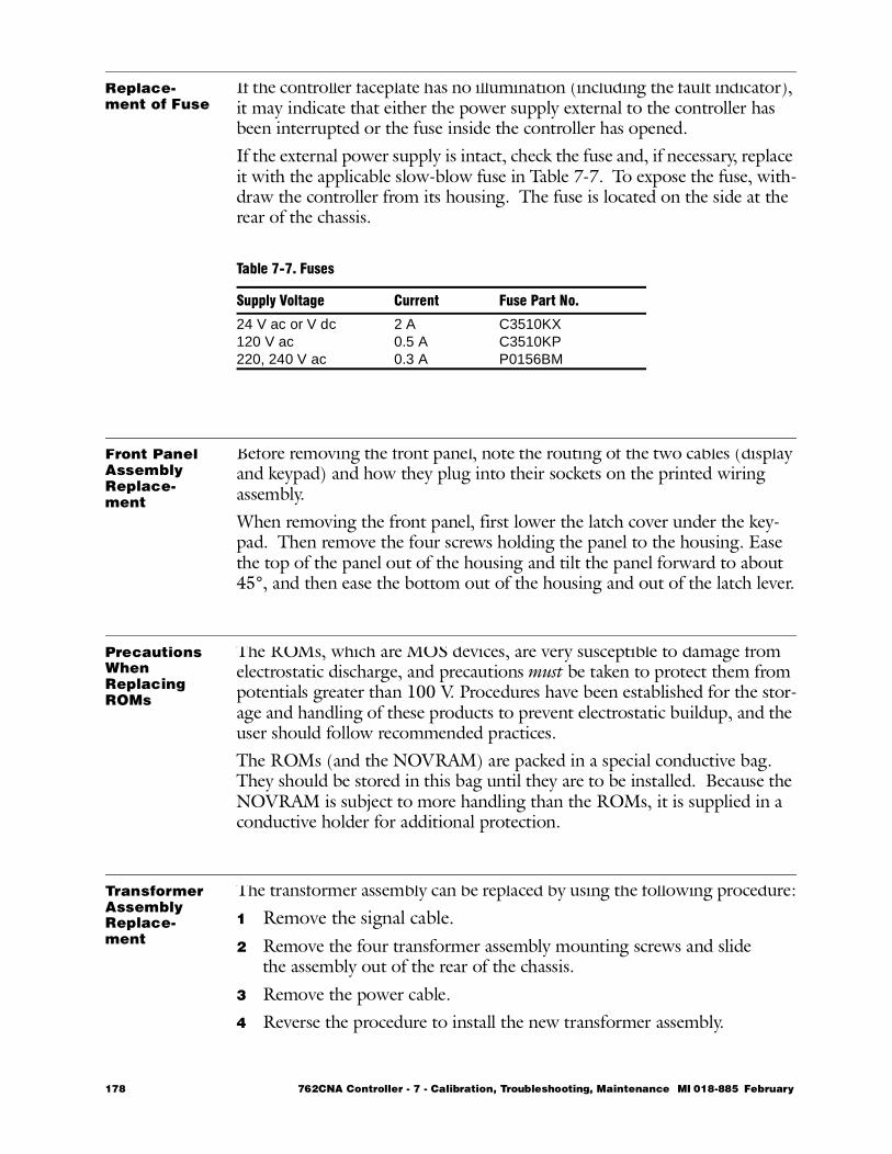
Replace-ment of Fuse
If the controller faceplate has no illumination (including the fault indicator), it may indicate that either the power supply external to the controller has been interrupted or the fuse inside the controller has opened.If the external power supply is intact, check the fuse and, if necessary, replace it with the applicable slow-blow fuse in Table 7-7. To expose the fuse, with-draw the controller from its housing. The fuse is located on the side at the rear of the chassis.
Front Panel Assembly Replace-ment
Before removing the front panel, note the routing of the two cables (display and keypad) and how they plug into their sockets on the printed wiring assembly.When removing the front panel, first lower the latch cover under the key-pad. Then remove the four screws holding the panel to the housing. Ease the top of the panel out of the housing and tilt the panel forward to about 45°, and then ease the bottom out of the housing and out of the latch lever.
Precautions When Replacing ROMs
The ROMs, which are MOS devices, are very susceptible to damage from electrostatic discharge, and precautions must be taken to protect them from potentials greater than 100 V. Procedures have been established for the stor-age and handling of these products to prevent electrostatic buildup, and the user should follow recommended practices.The ROMs (and the NOVRAM) are packed in a special conductive bag. They should be stored in this bag until they are to be installed. Because the NOVRAM is subject to more handling than the ROMs, it is supplied in a conductive holder for additional protection.
Transformer Assembly Replace-ment
The transformer assembly can be replaced by using the following procedure:1 Remove the signal cable.2 Remove the four transformer assembly mounting screws and slide
the assembly out of the rear of the chassis.3 Remove the power cable.4 Reverse the procedure to install the new transformer assembly.
Table 7-7. Fuses
Supply Voltage Current Fuse Part No.
24 V ac or V dc120 V ac220, 240 V ac
2 A0.5 A0.3 A
C3510KXC3510KPP0156BM
178 762CNA Controller - 7 - Calibration, Troubleshooting, Maintenance MI 018-885 February
RTD Input or Isolated Output PWA Replace-ment
These optional PWAs are installed side-by-side on the main component PWA (See Figure 7-11). Observe the following details when either option is a field installation:1 Remove jumper(s) from socket(s) of PWA being installed. Save
jumper(s) so it can be reinstalled later if option is to be removed.2 Plug PWA into its socket and insert mounting screws. Secure PWA
in place.
Replace-ment of Other Parts
The procedures to remove and reinstall other replaceable parts will be obvi-ous from Figure 7-11. Before removing a plug-in cable note its routing for correct reinstallation.
MI 018-885 February 1998 762CNA Controller - 7 - Calibration, Troubleshooting, Maintenance 179

180 762CNA Controller - 7 - Calibration, Troubleshooting, Maintenance MI 018-885 February

762C SINGLESTATION
MICROController
February 1998
Preface • xiii Chapter 1 Quick Check • 1 Chapter 2 Product Overview • 11 Chapter 3 Installation • 23 Chapter 4 Configuration • 49 Chapter 5 Operation • 109 Chapter 6 EXACT Tuning • 135 Chapter 7 Calibration, Troubleshooting,
Maintenance • 159 Ð Appendix A Specifications • 183
Appendix B Configuration Worksheets • 193 Appendix C Structure Diagrams • 237 Appendix D Parts List • 247 Appendix E Dimensional Print • 255 Appendix F Functional Diagram • 261 Glossary • 267 Index • 287
The Intelligent Automation People

182 762CNA Controller MI 018-885 February 1998
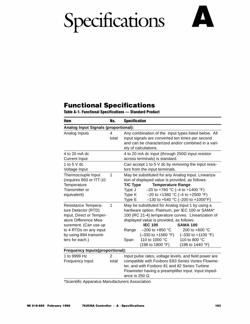
MI 018-885 Februar
A Specifications
Functional Specifications Table A-1. Functional Specifications — Standard Product
Item No. Specification
Analog Input Signals (proportional):Analog Inputs 4
totalAny combination of the input types listed below. All input signals are converted ten times per second and can be characterized and/or combined in a vari-ety of calculations.
4 to 20 mA dc Current Input
4 to 20 mA dc input (through 250Ω input resistor across terminals) is standard.
1 to 5 V dcVoltage Input
Can accept 1 to 5 V dc by removing the input resis-tors from the input terminals.
Thermocouple Input(requires 893 or ITT-10 Temperature Transmitter or equivalent)
1 May be substituted for any Analog Input. Lineariza-tion of displayed value is provided, as follows:T/C Type Temperature RangeType J –20 to +760 °C (–4 to +1400 °F)Type K –20 to +1380 °C (–4 to +2500 °F)Type E –130 to +540 °C (–200 to +1000°F)
Resistance Tempera-ture Detector (RTD) Input, Direct or Temper-ature Difference Mea-surement. (Can use up to 4 RTDs on any input by using 894 transmit-ters for each.)
1 May be substituted for Analog Input 1 by using a hardware option. Platinum, per IEC 100 or SAMA* 100 (RC 21-4) temperature curves. Linearization of displayed value is provided, as follows:
IEC 100 SAMA 100Range –200 to +850 °C 200 to +600 °C
(–330 to +1560 °F) (–330 to +1100 °F)Span 110 to 1000 °C 110 to 800 °C
(198 to 1800 °F) (198 to 1440 °F)Frequency Inputs(proportional):1 to 9999 HzFrequency Input
2 total
Input pulse rates, voltage levels, and field power are compatible with Foxboro E83 Series Vortex Flowme-ter, and with Foxboro 81 and 82 Series Turbine Flowmeter having a preamplifier input. Input imped-ance is 250 Ω.
*Scientific Apparatus Manufacturers Association
y 1998 762CNA Controller - A - Specifications 183
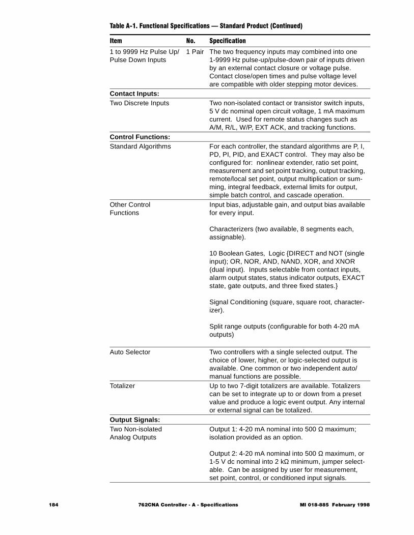
1 to 9999 Hz Pulse Up/ Pulse Down Inputs
1 Pair The two frequency inputs may combined into one 1-9999 Hz pulse-up/pulse-down pair of inputs driven by an external contact closure or voltage pulse. Contact close/open times and pulse voltage level are compatible with older stepping motor devices.
Contact Inputs:Two Discrete Inputs Two non-isolated contact or transistor switch inputs,
5 V dc nominal open circuit voltage, 1 mA maximum current. Used for remote status changes such as A/M, R/L, W/P, EXT ACK, and tracking functions.
Control Functions:Standard Algorithms For each controller, the standard algorithms are P, I,
PD, PI, PID, and EXACT control. They may also be configured for: nonlinear extender, ratio set point, measurement and set point tracking, output tracking, remote/local set point, output multiplication or sum-ming, integral feedback, external limits for output, simple batch control, and cascade operation.
Other Control Functions
Input bias, adjustable gain, and output bias available for every input.
Characterizers (two available, 8 segments each, assignable).
10 Boolean Gates, Logic DIRECT and NOT (single input); OR, NOR, AND, NAND, XOR, and XNOR (dual input). Inputs selectable from contact inputs, alarm output states, status indicator outputs, EXACT state, gate outputs, and three fixed states.
Signal Conditioning (square, square root, character-izer).
Split range outputs (configurable for both 4-20 mA outputs)
Auto Selector Two controllers with a single selected output. The choice of lower, higher, or logic-selected output is available. One common or two independent auto/manual functions are possible.
Totalizer Up to two 7-digit totalizers are available. Totalizers can be set to integrate up to or down from a preset value and produce a logic event output. Any internal or external signal can be totalized.
Output Signals:Two Non-isolated Analog Outputs
Output 1: 4-20 mA nominal into 500 Ω maximum; isolation provided as an option.
Output 2: 4-20 mA nominal into 500 Ω maximum, or 1-5 V dc nominal into 2 kΩ minimum, jumper select-able. Can be assigned by user for measurement, set point, control, or conditioned input signals.
Table A-1. Functional Specifications — Standard Product (Continued)
Item No. Specification
184 762CNA Controller - A - Specifications MI 018-885 February 1998
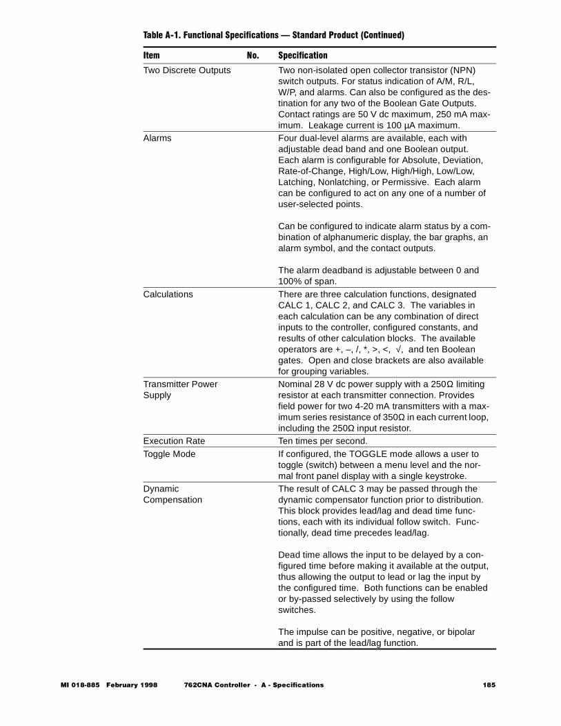
Two Discrete Outputs Two non-isolated open collector transistor (NPN) switch outputs. For status indication of A/M, R/L, W/P, and alarms. Can also be configured as the des-tination for any two of the Boolean Gate Outputs. Contact ratings are 50 V dc maximum, 250 mA max-imum. Leakage current is 100 µA maximum.
Alarms Four dual-level alarms are available, each with adjustable dead band and one Boolean output. Each alarm is configurable for Absolute, Deviation, Rate-of-Change, High/Low, High/High, Low/Low, Latching, Nonlatching, or Permissive. Each alarm can be configured to act on any one of a number of user-selected points.
Can be configured to indicate alarm status by a com-bination of alphanumeric display, the bar graphs, an alarm symbol, and the contact outputs.
The alarm deadband is adjustable between 0 and 100% of span.
Calculations There are three calculation functions, designated CALC 1, CALC 2, and CALC 3. The variables in each calculation can be any combination of direct inputs to the controller, configured constants, and results of other calculation blocks. The available operators are +, –, /, *, >, <, √, and ten Boolean gates. Open and close brackets are also available for grouping variables.
Transmitter Power Supply
Nominal 28 V dc power supply with a 250Ω limiting resistor at each transmitter connection. Provides field power for two 4-20 mA transmitters with a max-imum series resistance of 350Ω in each current loop, including the 250Ω input resistor.
Execution Rate Ten times per second.Toggle Mode If configured, the TOGGLE mode allows a user to
toggle (switch) between a menu level and the nor-mal front panel display with a single keystroke.
Dynamic Compensation
The result of CALC 3 may be passed through the dynamic compensator function prior to distribution. This block provides lead/lag and dead time func-tions, each with its individual follow switch. Func-tionally, dead time precedes lead/lag.
Dead time allows the input to be delayed by a con-figured time before making it available at the output, thus allowing the output to lead or lag the input by the configured time. Both functions can be enabled or by-passed selectively by using the follow switches.
The impulse can be positive, negative, or bipolar and is part of the lead/lag function.
Table A-1. Functional Specifications — Standard Product (Continued)
Item No. Specification
MI 018-885 February 1998 762CNA Controller - A - Specifications 185
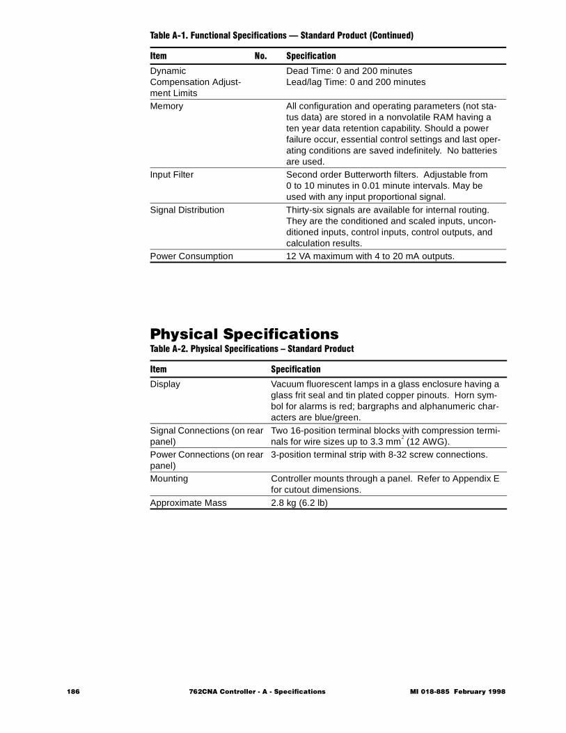
Physical Specifications
Dynamic Compensation Adjust-ment Limits
Dead Time: 0 and 200 minutesLead/lag Time: 0 and 200 minutes
Memory All configuration and operating parameters (not sta-tus data) are stored in a nonvolatile RAM having a ten year data retention capability. Should a power failure occur, essential control settings and last oper-ating conditions are saved indefinitely. No batteries are used.
Input Filter Second order Butterworth filters. Adjustable from 0 to 10 minutes in 0.01 minute intervals. May be used with any input proportional signal.
Signal Distribution Thirty-six signals are available for internal routing. They are the conditioned and scaled inputs, uncon-ditioned inputs, control inputs, control outputs, and calculation results.
Power Consumption 12 VA maximum with 4 to 20 mA outputs.
Table A-2. Physical Specifications – Standard Product
Item Specification
Display Vacuum fluorescent lamps in a glass enclosure having a glass frit seal and tin plated copper pinouts. Horn sym-bol for alarms is red; bargraphs and alphanumeric char-acters are blue/green.
Signal Connections (on rear panel)
Two 16-position terminal blocks with compression termi-nals for wire sizes up to 3.3 mm
2 (12 AWG).
Power Connections (on rear panel)
3-position terminal strip with 8-32 screw connections.
Mounting Controller mounts through a panel. Refer to Appendix E for cutout dimensions.
Approximate Mass 2.8 kg (6.2 lb)
Table A-1. Functional Specifications — Standard Product (Continued)
Item No. Specification
186 762CNA Controller - A - Specifications MI 018-885 February 1998

Operating and Storage Conditions
Electrical Safety Specifications
NOTE These controllers have been designed to meet the electrical safety descriptions listed in the table above. For detailed information or status of testing laboratory approvals/certifications, contact Foxboro.
Table A-3. Operating and Storage Conditions
Influence
Reference Operating Conditions
Normal Operating Condition Limits
Operative Limits
Transportation and Storage Limits
Ambient Tempera-ture
23±2°C(73±3°F)
-10 and +60°C(15 and 140°F)
-10 and +60°C *(15 and 140°F)
-40 and +70°C(-40 and +160°F)
Relative Humidity
50±10% 5 and 95%noncondensing
5 and 95%noncondensing
0 and 100%noncondensing
Supply Voltage
24,120,220 and 240 V ac, ±1%24 V dc, ±1%
V ac, +10, -15%V dc, +10, -15%
V ac, +15, -20%V dc, +10, -15%
NA
Supply Frequency
50/60 Hz, ±0.1 Hz
50/60 Hz, ±3 Hz
47 and 63 Hz NA
Vibration Negligible 5 and 200 Hz at an acceleration of 2.5 m/s/s
-- 10 m/s/s (1g) for 1 hour when in shipping con-tainer
Mechanical Shock
Negligible -- -- A 42-inch drop when in shipping container
*Lower operative limit extends to -20°C (-5°F) with Enclosure Heater option.
Table A-4. Electrical Classification
Testing Laboratory, Types of Protection, and Area Classification Application Conditions
Electrical SafetyDesign Code
CSA for use in Ordinary Locations.
Controllers without a hous-ing are not approved.
CS-E/CG-A
CSA for Class I, Division 2, Groups A, B, C, and D.
Controllers without a hous-ing are not approved. Tem-perature Code T5.
CS-E/CN-A
FM for Class I, Division 2, Groups A, B, C, and D.
Temperature Code T5.Controllers without a hous-ing are not approved.
CS-E/FN-A
MI 018-885 February 1998 762CNA Controller - A - Specifications 187
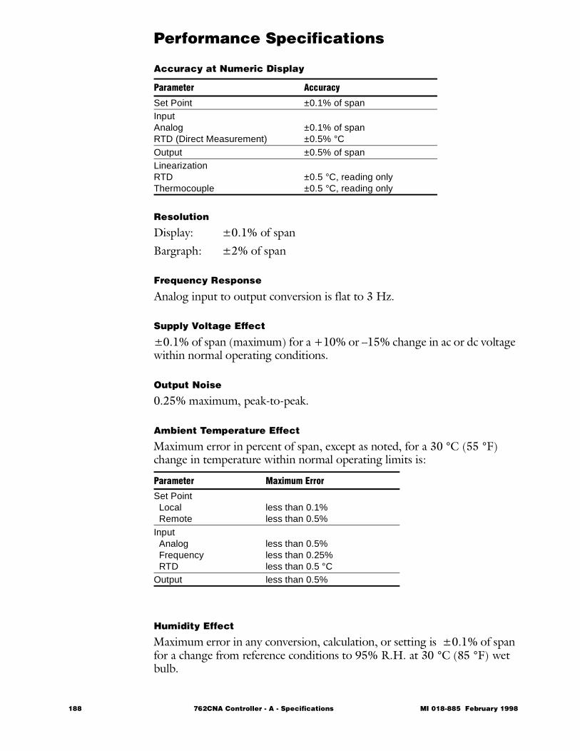
Performance Specifications
Accuracy at Numeric Display
Resolution
Display: ±0.1% of spanBargraph: ±2% of span
Frequency Response
Analog input to output conversion is flat to 3 Hz.
Supply Voltage Effect
±0.1% of span (maximum) for a +10% or –15% change in ac or dc voltage within normal operating conditions.
Output Noise
0.25% maximum, peak-to-peak.
Ambient Temperature Effect
Maximum error in percent of span, except as noted, for a 30 °C (55 °F) change in temperature within normal operating limits is:
Humidity Effect
Maximum error in any conversion, calculation, or setting is ±0.1% of span for a change from reference conditions to 95% R.H. at 30 °C (85 °F) wet bulb.
Parameter Accuracy
Set Point ±0.1% of spanInputAnalogRTD (Direct Measurement)
±0.1% of span±0.5% °C
Output ±0.5% of spanLinearizationRTDThermocouple
±0.5 °C, reading only±0.5 °C, reading only
Parameter Maximum Error
Set Point Local Remote
less than 0.1%less than 0.5%
Input Analog Frequency RTD
less than 0.5%less than 0.25%less than 0.5 °C
Output less than 0.5%
188 762CNA Controller - A - Specifications MI 018-885 February 1998
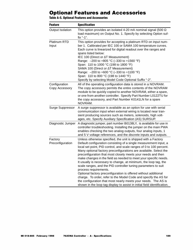
Optional Features and AccessoriesTable A-5. Optional Features and Accessories
Feature Specification
Output Isolation This option provides an isolated 4-20 mA nominal signal (500 Ω load maximum) on Output No. 1. Specify by selecting Option suf-fix “-1”.
Platinum RTD Input
This option provides for accepting a platinum RTD on input num-ber 1. Calibrated per IEC 100 or SAMA 100 temperature curves. Each curve is linearized for digital readout over the ranges and spans listed below:IEC 100 (Direct or ∆T Measurement)Range: –200 to +805 °C (–330 to +1560 °F)Span: 110 to 1000 °C (198 to 1800 °F)SAMA 100 (Direct or ∆T Measurement)Range: –200 to +600 °C (–330 to +1100 °F)Span: 110 to 800 °C (198 to 1440 °F)Specify by selecting Model Code Optional Suffix “-2”.
Configuration Copy Accessory
All of the operating configuration data is stored in a NOVRAM. The copy accessory permits the entire contents of the NOVRAM module to be quickly copied to another NOVRAM, either a spare, or one from another controller. Specify Part Number L0122TU for the copy accessory, and Part Number K0141LN for a spare NOVRAM.
Surge Suppressor A surge suppressor is available as an option for use with serial communication input when external wiring is located near tran-sient producing sources such as meters, solenoids, high volt-ages, etc. Specify Auxiliary Specification (AS) SURSUP.
Diagnostic Jumper A diagnostic jumper, part number B0138LY, is available for use in controller troubleshooting. Installing the jumper on the main PWA enables checking the two analog outputs, four analog inputs, 1 and 5 V voltage references, and the discrete inputs and outputs.
Factory Preconfiguration
Unless otherwise specified, the unit is shipped with a Factory Default configuration consisting of a single measurement input, a local set point, PID control, and scale ranges of 0 to 100 percent.Many optional factory preconfigurations are available. Select the preconfiguration that most closely meets your needs and then make changes in the field as needed to meet your specific needs. It usually is necessary to change, at minimum, the loop tag, the scale ranges, and the PID controller tuning parameters to suit process requirements.Optional factory preconfiguration is offered without additional charge. To order, refer to the Model Code and specify the AS for the configuration that most nearly meets your needs. The AS is shown in the loop tag display to assist in initial field identification.
MI 018-885 February 1998 762CNA Controller - A - Specifications 189

190 762CNA Controller - A - Specifications MI 018-885 February 1998

762C SINGLESTATION
MICROController
February 1998
Preface • xiii Chapter 1 Quick Check • 1 Chapter 2 Product Overview • 11 Chapter 3 Installation • 23 Chapter 4 Configuration • 49 Chapter 5 Operation • 109 Chapter 6 EXACT Tuning • 135 Chapter 7 Calibration, Troubleshooting,
Maintenance • 159 Appendix A Specifications • 183
Ð Appendix B Configuration Worksheets • 193 Appendix C Structure Diagrams • 237 Appendix D Parts List • 247 Appendix E Dimensional Print • 255 Appendix F Functional Diagram • 261 Glossary • 267 Index • 287
The Intelligent Automation People

192 762CNA Controller MI 018-885 February 1998
MI 018-885 Februar
B Configuration Worksheets
This appendix contains information that will help you configure your con-troller. Table B-5 contains the actual configuration worksheets. Figure B-1 defines the content of the worksheets. Tables B-1, B-2, B-3, and B-4 contain refer-ence data needed for making configuration entries.This appendix also contains diagrams of optional factory preconfiguration options that may have been specified. The Auxiliary Specification (AS) ref-erence code used to specify a preconfiguration option is initially displayed in the looptag position on the controller faceplate to assist you in initial field identification.
y 1998 762CNA Controller - B - Configuration Worksheets 193
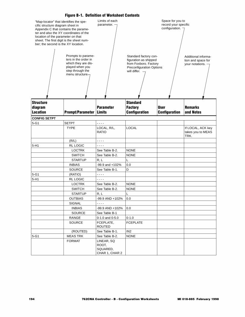
Figure B-1. Definition of Worksheet Contents
StructurediagramLocation Prompt/Parameter
ParameterLimits
StandardFactoryConfiguration
User Configuration
Remarksand Notes
CONFIG SETPT
5-G1 SETPT - - - -
TYPE LOCAL, R/L, RATIO
LOCAL If LOCAL, ACK key takes you to MEAS TRK.
(R/L) - - - -
5-H1 RL LOGIC - - - -
LOCTRK See Table B-2. NONE
SWITCH See Table B-2. NONE
STARTUP R, L L
INBIAS -99.9 and +102% 0.0
SOURCE See Table B-1. D
5-G1 (RATIO) - - - -
5-H1 RL LOGIC - - - -
LOCTRK See Table B-2. NONE
SWITCH See Table B-2. NONE
STARTUP R, L L
OUTBIAS -99.9 AND +102% 0.0
SIGNAL - - - -
INBIAS -99.9 AND +102% 0.0
SOURCE See Table B-1
RANGE 0-1.0 and 0-5.0 0-1.0
SOURCE FCEPLATE, ROUTED
FCEPLATE
(ROUTED) See Table B-1. IN2
5-G1 MEAS TRK See Table B-2. NONE
FORMAT LINEAR, SQ ROOT, SQUARED, CHAR 1, CHAR 2
Prompts to parame-ters in the order in which they are dis-played when you step through the menu structure.
Limits of each parameter.
Standard factory con-figuration as shipped from Foxboro. Factory
Space for you to record your specific configuration.
Additional informa-tion and space for your notations.
Preconfiguration Optionswill differ.
“Map-locator” that identifies the spe-cific structure diagram sheet in Appendix C that contains the parame-ter and also the XY coordinates of the location of the parameter on that sheet. The first digit is the sheet num-ber; the second is the XY location.
194 762CNA Controller - B - Configuration Worksheets MI 018-885 February 1998
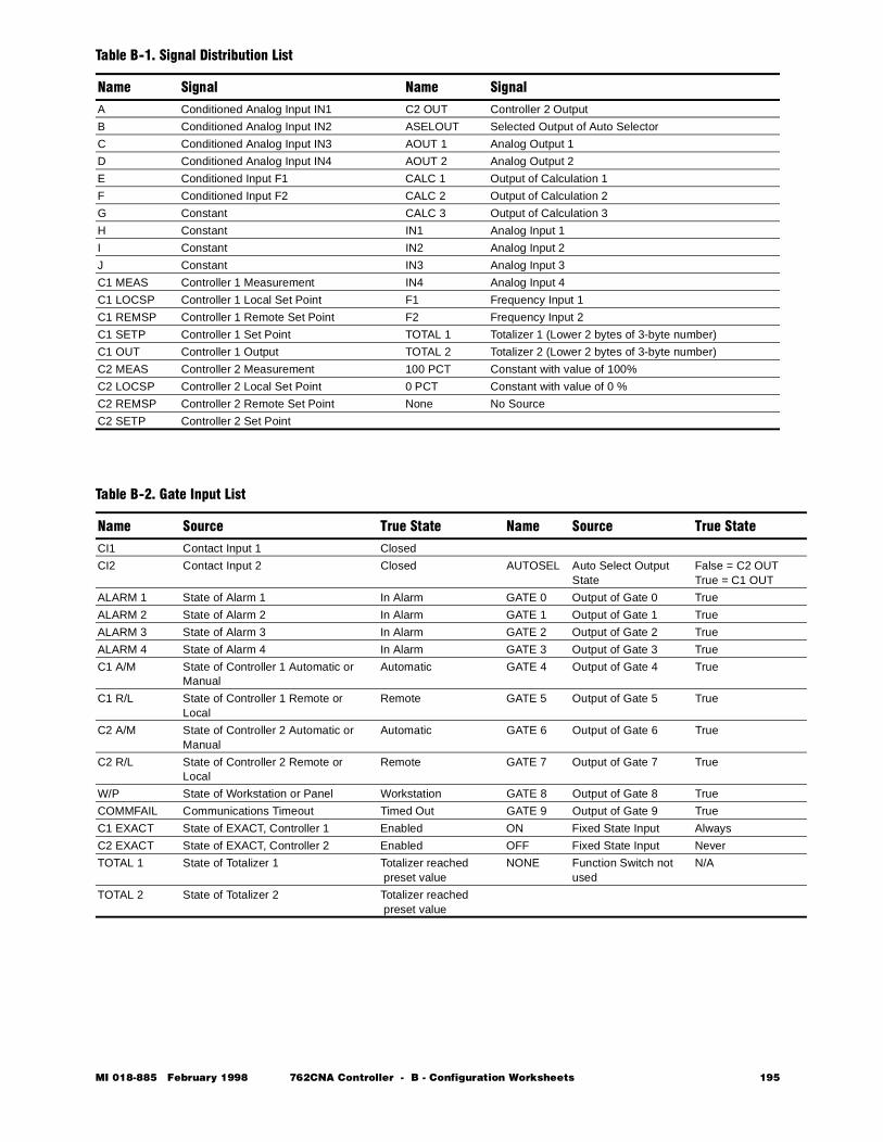
Table B-1. Signal Distribution List
Name Signal Name SignalA Conditioned Analog Input IN1 C2 OUT Controller 2 Output
B Conditioned Analog Input IN2 ASELOUT Selected Output of Auto Selector
C Conditioned Analog Input IN3 AOUT 1 Analog Output 1
D Conditioned Analog Input IN4 AOUT 2 Analog Output 2
E Conditioned Input F1 CALC 1 Output of Calculation 1
F Conditioned Input F2 CALC 2 Output of Calculation 2
G Constant CALC 3 Output of Calculation 3
H Constant IN1 Analog Input 1
I Constant IN2 Analog Input 2
J Constant IN3 Analog Input 3
C1 MEAS Controller 1 Measurement IN4 Analog Input 4
C1 LOCSP Controller 1 Local Set Point F1 Frequency Input 1
C1 REMSP Controller 1 Remote Set Point F2 Frequency Input 2
C1 SETP Controller 1 Set Point TOTAL 1 Totalizer 1 (Lower 2 bytes of 3-byte number)
C1 OUT Controller 1 Output TOTAL 2 Totalizer 2 (Lower 2 bytes of 3-byte number)
C2 MEAS Controller 2 Measurement 100 PCT Constant with value of 100%
C2 LOCSP Controller 2 Local Set Point 0 PCT Constant with value of 0 %
C2 REMSP Controller 2 Remote Set Point None No Source
C2 SETP Controller 2 Set Point
Table B-2. Gate Input List
Name Source True State Name Source True StateCI1 Contact Input 1 Closed
CI2 Contact Input 2 Closed AUTOSEL Auto Select Output State
False = C2 OUT True = C1 OUT
ALARM 1 State of Alarm 1 In Alarm GATE 0 Output of Gate 0 True
ALARM 2 State of Alarm 2 In Alarm GATE 1 Output of Gate 1 True
ALARM 3 State of Alarm 3 In Alarm GATE 2 Output of Gate 2 True
ALARM 4 State of Alarm 4 In Alarm GATE 3 Output of Gate 3 True
C1 A/M State of Controller 1 Automatic or Manual
Automatic GATE 4 Output of Gate 4 True
C1 R/L State of Controller 1 Remote or Local
Remote GATE 5 Output of Gate 5 True
C2 A/M State of Controller 2 Automatic or Manual
Automatic GATE 6 Output of Gate 6 True
C2 R/L State of Controller 2 Remote or Local
Remote GATE 7 Output of Gate 7 True
W/P State of Workstation or Panel Workstation GATE 8 Output of Gate 8 True
COMMFAIL Communications Timeout Timed Out GATE 9 Output of Gate 9 True
C1 EXACT State of EXACT, Controller 1 Enabled ON Fixed State Input Always
C2 EXACT State of EXACT, Controller 2 Enabled OFF Fixed State Input Never
TOTAL 1 State of Totalizer 1 Totalizer reached preset value
NONE Function Switch not used
N/A
TOTAL 2 State of Totalizer 2 Totalizer reached preset value
MI 018-885 February 1998 762CNA Controller - B - Configuration Worksheets 195
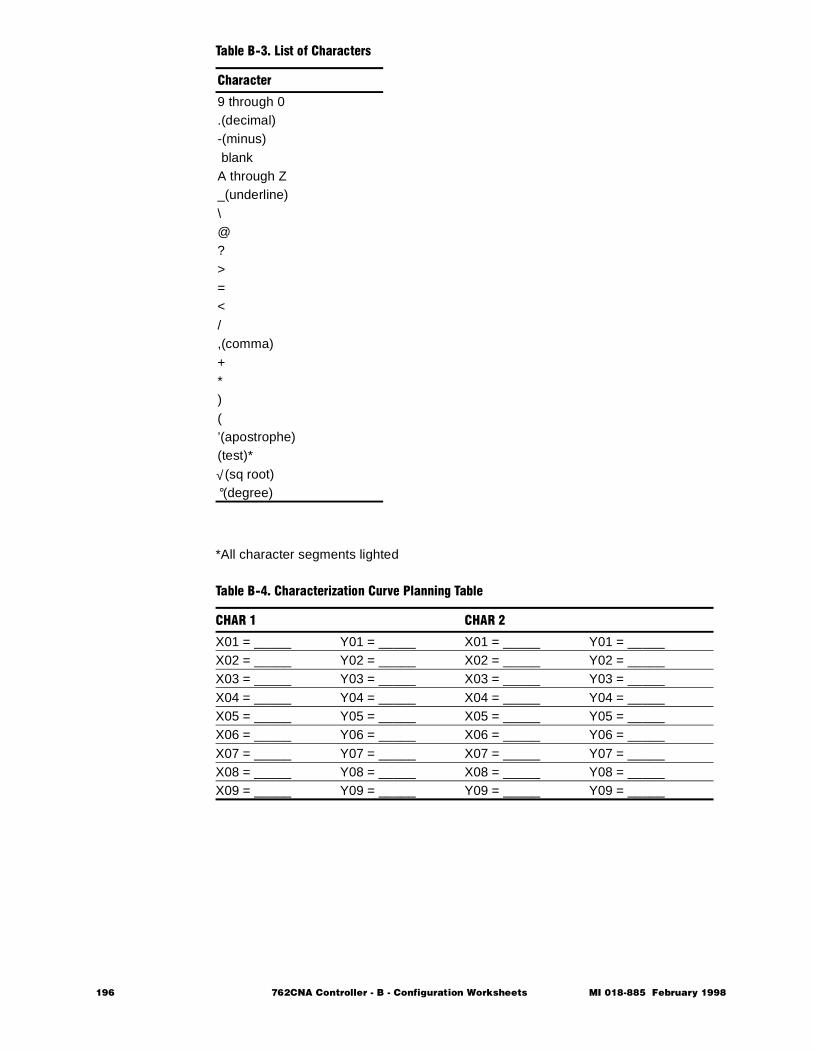
*All character segments lighted
Table B-3. List of Characters
Character
9 through 0.(decimal)-(minus) blankA through Z_(underline)\@?>=</,(comma)+*)(’(apostrophe)(test)*
√ (sq root)°(degree)
Table B-4. Characterization Curve Planning Table
CHAR 1 CHAR 2
X01 = _____ Y01 = _____ X01 = _____ Y01 = _____X02 = _____ Y02 = _____ X02 = _____ Y02 = _____X03 = _____ Y03 = _____ X03 = _____ Y03 = _____X04 = _____ Y04 = _____ X04 = _____ Y04 = _____X05 = _____ Y05 = _____ X05 = _____ Y05 = _____X06 = _____ Y06 = _____ X06 = _____ Y06 = _____X07 = _____ Y07 = _____ X07 = _____ Y07 = _____X08 = _____ Y08 = _____ X08 = _____ Y08 = _____X09 = _____ Y09 = _____ Y09 = _____ Y09 = _____
196 762CNA Controller - B - Configuration Worksheets MI 018-885 February 1998
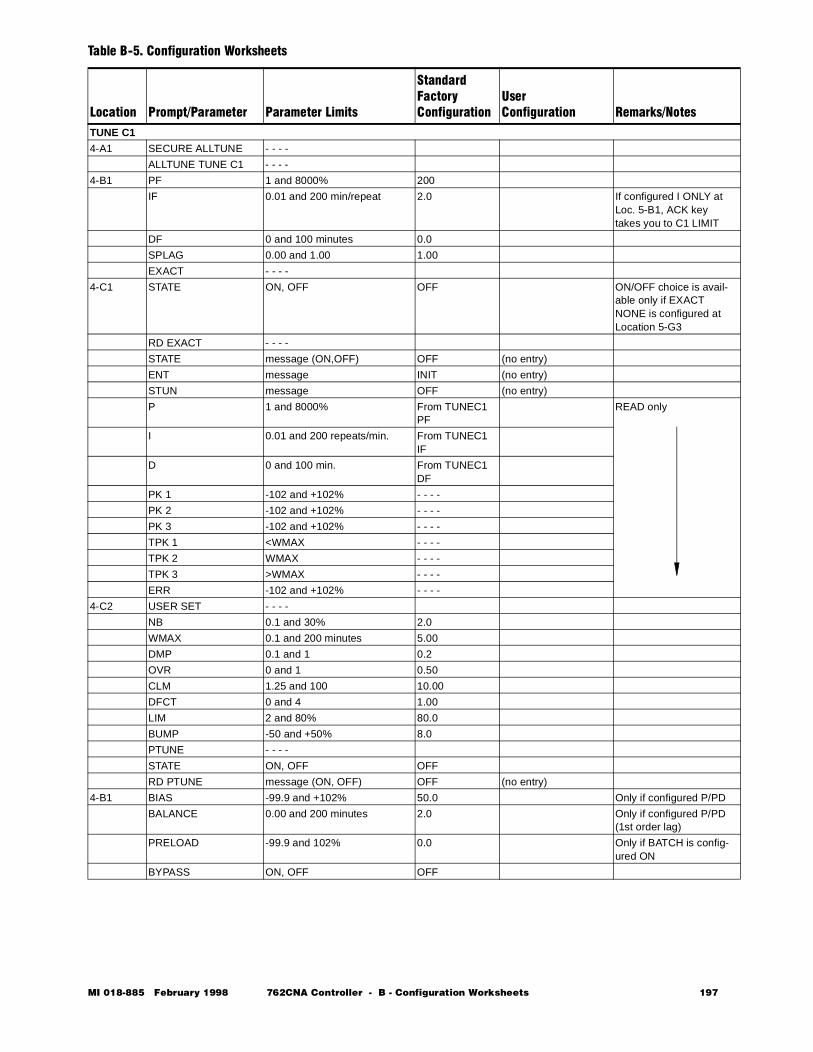
Table B-5. Configuration Worksheets
Location Prompt/Parameter Parameter Limits
StandardFactoryConfiguration
UserConfiguration Remarks/Notes
TUNE C1
4-A1 SECURE ALLTUNE - - - -
ALLTUNE TUNE C1 - - - -
4-B1 PF 1 and 8000% 200
IF 0.01 and 200 min/repeat 2.0 If configured I ONLY at Loc. 5-B1, ACK key takes you to C1 LIMIT
DF 0 and 100 minutes 0.0
SPLAG 0.00 and 1.00 1.00
EXACT - - - -
4-C1 STATE ON, OFF OFF ON/OFF choice is avail-able only if EXACT NONE is configured at Location 5-G3
RD EXACT - - - -
STATE message (ON,OFF) OFF (no entry)
ENT message INIT (no entry)
STUN message OFF (no entry)
P 1 and 8000% From TUNEC1 PF
READ only
I 0.01 and 200 repeats/min. From TUNEC1 IF
D 0 and 100 min. From TUNEC1 DF
PK 1 -102 and +102% - - - -
PK 2 -102 and +102% - - - -
PK 3 -102 and +102% - - - -
TPK 1 <WMAX - - - -
TPK 2 WMAX - - - -
TPK 3 >WMAX - - - -
ERR -102 and +102% - - - -
4-C2 USER SET - - - -
NB 0.1 and 30% 2.0
WMAX 0.1 and 200 minutes 5.00
DMP 0.1 and 1 0.2
OVR 0 and 1 0.50
CLM 1.25 and 100 10.00
DFCT 0 and 4 1.00
LIM 2 and 80% 80.0
BUMP -50 and +50% 8.0
PTUNE - - - -
STATE ON, OFF OFF
RD PTUNE message (ON, OFF) OFF (no entry)
4-B1 BIAS -99.9 and +102% 50.0 Only if configured P/PD
BALANCE 0.00 and 200 minutes 2.0 Only if configured P/PD(1st order lag)
PRELOAD -99.9 and 102% 0.0 Only if BATCH is config-ured ON
BYPASS ON, OFF OFF
MI 018-885 February 1998 762CNA Controller - B - Configuration Worksheets 197
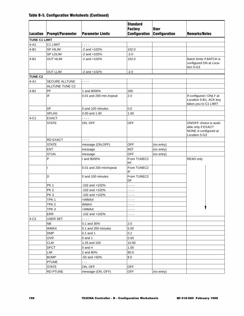
TUNE C1 LIMIT
4-A1 C1 LIMIT - - - -
4-B1 SP HILIM -2 and +102% 102.0
SP LOLIM -2 and +102% -2.0
4-B1 OUT HLIM -2 and +102% 102.0 Batch limits if BATCH is configured ON at Loca-tion 5-G3
OUT LLIM -2 and +102% -2.0
TUNE C2
4-A1 SECURE ALLTUNE - - - -
ALLTUNE TUNE C2
4-B1 PF 1 and 8000% 200
IF 0.01 and 200 min./repeat 2.0 If configured I ONLY at Location 5-B1, ACK key takes you to C1 LIMIT
DF 0 and 100 minutes 0.0
SPLAG 0.00 and 1.00 1.00
4-C1 EXACT - - - -
STATE ON, OFF OFF ON/OFF choice is avail-able only if EXACT NONE is configured at Location 5-G3
RD EXACT - - - -
STATE message (ON,OFF) OFF (no entry)
ENT message INIT (no entry)
STUN message OFF (no entry)
P I and 8000% From TUNEC2 PF
READ only
I 0.01 and 200 min/repeat From TUNEC2 IF
D 0 and 100 minutes From TUNEC2 DF
PK 1 -102 and +102% - - - -
PK 2 -102 and +102% - - - -
PK 3 -102 and +102% - - - -
TPK 1 <WMAX - - - -
TPK 2 WMAX - - - -
TPK 3 >WMAX - - - -
ERR -102 and +102% - - - -
4-C2 USER SET - - - -
NB 0.1 and 30% 2.0
WMAX 0.1 and 200 minutes 5.00
DMP 0.1 and 1 0.2
OVR 0 and 1 0.50
CLM 1.25 and 100 10.00
DFCT 0 and 4 1.00
LIM 2 and 80% 80.0
BUMP -50 and +50% 8.0
PTUNE - - -
STATE ON, OFF OFF
RD PTUNE message (ON, OFF) OFF (no entry)
Table B-5. Configuration Worksheets (Continued)
Location Prompt/Parameter Parameter Limits
StandardFactoryConfiguration
UserConfiguration Remarks/Notes
198 762CNA Controller - B - Configuration Worksheets MI 018-885 February 1998
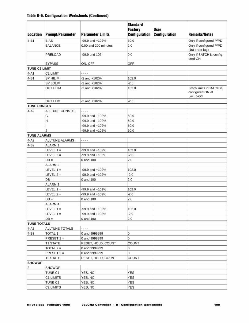
4-B1 BIAS -99.9 and +102% 50.0 Only if configured P/PD
BALANCE 0.00 and 200 minutes 2.0 Only if configured P/PD(1st order lag)
PRELOAD -99.9 and 102 0.0 Only if BATCH is config-ured ON
BYPASS ON, OFF OFF
TUNE C2 LIMIT
4-A1 C2 LIMIT - - - -
4-B1 SP HILIM -2 and +102% 102.0
SP LOLIM -2 and +102% -2.0
OUT HLIM -2 and +102% 102.0 Batch limits if BATCH is configured ON atLoc. 5-G3
OUT LLIM -2 and +102% -2.0
TUNE CONSTS
4-A2 ALLTUNE CONSTS - - - -
G -99.9 and +102% 50.0
H -99.9 and +102% 50.0
I -99.9 and +102% 50.0
J -99.9 and +102% 50.0
TUNE ALARMS
4-A2 ALLTUNE ALARMS - - - -
4-B2 ALARM 1
LEVEL 1 = -99.9 and +102% 102.0
LEVEL 2 = -99.9 and +102% -2.0
DB = 0 and 100 2.0
ALARM 2
LEVEL 1 = -99.9 and +102% 102.0
LEVEL 2 = -99.9 and +102% -2.0
DB = 0 and 100 2.0
ALARM 3
LEVEL 1 = -99.9 and +102% 102.0
LEVEL 2 = -99.9 and +102% -2.0
DB = 0 and 100 2.0
ALARM 4
LEVEL 1 = -99.9 and +102% 102.0
LEVEL 1 = -99.9 and +102% -2.0
DB = 0 and 100 2.0
TUNE TOTALS
4-A3 ALLTUNE TOTALS - - - -
4-B3 TOTAL 1 = 0 and 9999999 0
PRESET 1 = 0 and 9999999 0
T1 STATE RESET, HOLD, COUNT COUNT
TOTAL 2 = 0 and 9999999 0
PRESET 2 = 0 and 9999999 0
T2 STATE RESET, HOLD, COUNT COUNT
SHOWOP
2 SHOWOP - - - -
TUNE C1 YES, NO YES
C1 LIMITS YES, NO YES
TUNE C2 YES, NO YES
C2 LIMITS YES, NO YES
Table B-5. Configuration Worksheets (Continued)
Location Prompt/Parameter Parameter Limits
StandardFactoryConfiguration
UserConfiguration Remarks/Notes
MI 018-885 February 1998 762CNA Controller - B - Configuration Worksheets 199
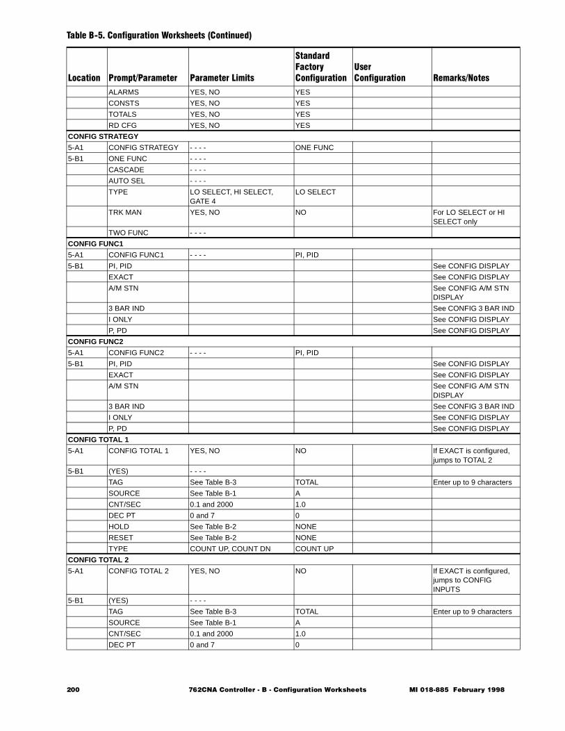
ALARMS YES, NO YES
CONSTS YES, NO YES
TOTALS YES, NO YES
RD CFG YES, NO YES
CONFIG STRATEGY
5-A1 CONFIG STRATEGY - - - - ONE FUNC
5-B1 ONE FUNC - - - -
CASCADE - - - -
AUTO SEL - - - -
TYPE LO SELECT, HI SELECT, GATE 4
LO SELECT
TRK MAN YES, NO NO For LO SELECT or HI SELECT only
TWO FUNC - - - -
CONFIG FUNC1
5-A1 CONFIG FUNC1 - - - - PI, PID
5-B1 PI, PID See CONFIG DISPLAY
EXACT See CONFIG DISPLAY
A/M STN See CONFIG A/M STN DISPLAY
3 BAR IND See CONFIG 3 BAR IND
I ONLY See CONFIG DISPLAY
P, PD See CONFIG DISPLAY
CONFIG FUNC2
5-A1 CONFIG FUNC2 - - - - PI, PID
5-B1 PI, PID See CONFIG DISPLAY
EXACT See CONFIG DISPLAY
A/M STN See CONFIG A/M STN DISPLAY
3 BAR IND See CONFIG 3 BAR IND
I ONLY See CONFIG DISPLAY
P, PD See CONFIG DISPLAY
CONFIG TOTAL 1
5-A1 CONFIG TOTAL 1 YES, NO NO If EXACT is configured, jumps to TOTAL 2
5-B1 (YES) - - - -
TAG See Table B-3 TOTAL Enter up to 9 characters
SOURCE See Table B-1 A
CNT/SEC 0.1 and 2000 1.0
DEC PT 0 and 7 0
HOLD See Table B-2 NONE
RESET See Table B-2 NONE
TYPE COUNT UP, COUNT DN COUNT UP
CONFIG TOTAL 2
5-A1 CONFIG TOTAL 2 YES, NO NO If EXACT is configured, jumps to CONFIG INPUTS
5-B1 (YES) - - - -
TAG See Table B-3 TOTAL Enter up to 9 characters
SOURCE See Table B-1 A
CNT/SEC 0.1 and 2000 1.0
DEC PT 0 and 7 0
Table B-5. Configuration Worksheets (Continued)
Location Prompt/Parameter Parameter Limits
StandardFactoryConfiguration
UserConfiguration Remarks/Notes
200 762CNA Controller - B - Configuration Worksheets MI 018-885 February 1998
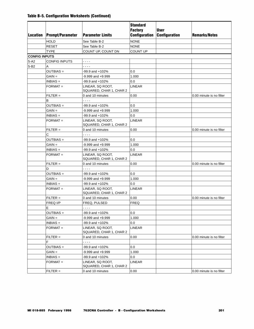
HOLD See Table B-2 NONE
RESET See Table B-2 NONE
TYPE COUNT UP, COUNT DN COUNT UP
CONFIG INPUTS
5-A2 CONFIG INPUTS - - - -
5-B2 A - - - -
OUTBIAS = -99.9 and +102% 0.0
GAIN = -9.999 and +9.999 1.000
INBIAS = -99.9 and +102% 0.0
FORMAT = LINEAR, SQ ROOT, SQUARED, CHAR 1, CHAR 2
LINEAR
FILTER = 0 and 10 minutes 0.00 0.00 minute is no filter
B - - - -
OUTBIAS = -99.9 and +102% 0.0
GAIN = -9.999 and +9.999 1.000
INBIAS = -99.9 and +102% 0.0
FORMAT = LINEAR, SQ ROOT, SQUARED, CHAR 1, CHAR 2
LINEAR
FILTER = 0 and 10 minutes 0.00 0.00 minute is no filter
C - - - -
OUTBIAS = -99.9 and +102% 0.0
GAIN = -9.999 and +9.999 1.000
INBIAS = -99.9 and +102% 0.0
FORMAT = LINEAR, SQ ROOT, SQUARED, CHAR 1, CHAR 2
LINEAR
FILTER = 0 and 10 minutes 0.00 0.00 minute is no filter
D - - - -
OUTBIAS = -99.9 and +102% 0.0
GAIN = -9.999 and +9.999 1.000
INBIAS = -99.9 and +102% 0.0
FORMAT = LINEAR, SQ ROOT, SQUARED, CHAR 1, CHAR 2
LINEAR
FILTER = 0 and 10 minutes 0.00 0.00 minute is no filter
FREQ I/P FREQ, PULSED FREQ
E - - - -
OUTBIAS = -99.9 and +102% 0.0
GAIN = -9.999 and +9.999 1.000
INBIAS = -99.9 and +102% 0.0
FORMAT = LINEAR, SQ ROOT, SQUARED, CHAR 1, CHAR 2
LINEAR
FILTER = 0 and 10 minutes 0.00 0.00 minute is no filter
F - - - -
OUTBIAS = -99.9 and +102% 0.0
GAIN = -9.999 and +9.999 1.000
INBIAS = -99.9 and +102% 0.0
FORMAT = LINEAR, SQ ROOT, SQUARED, CHAR 1, CHAR 2
LINEAR
FILTER = 0 and 10 minutes 0.00 0.00 minute is no filter
Table B-5. Configuration Worksheets (Continued)
Location Prompt/Parameter Parameter Limits
StandardFactoryConfiguration
UserConfiguration Remarks/Notes
MI 018-885 February 1998 762CNA Controller - B - Configuration Worksheets 201
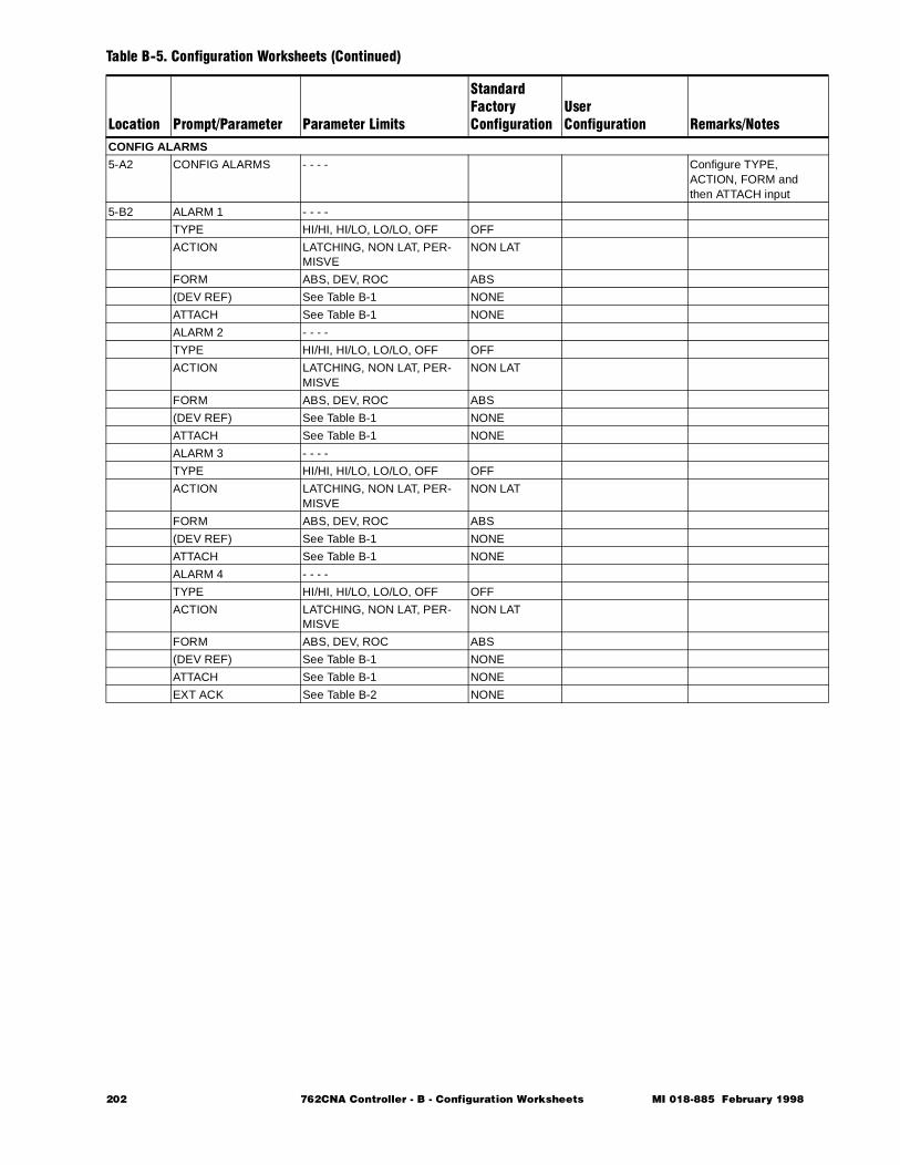
CONFIG ALARMS
5-A2 CONFIG ALARMS - - - - Configure TYPE, ACTION, FORM and then ATTACH input
5-B2 ALARM 1 - - - -
TYPE HI/HI, HI/LO, LO/LO, OFF OFF
ACTION LATCHING, NON LAT, PER-MISVE
NON LAT
FORM ABS, DEV, ROC ABS
(DEV REF) See Table B-1 NONE
ATTACH See Table B-1 NONE
ALARM 2 - - - -
TYPE HI/HI, HI/LO, LO/LO, OFF OFF
ACTION LATCHING, NON LAT, PER-MISVE
NON LAT
FORM ABS, DEV, ROC ABS
(DEV REF) See Table B-1 NONE
ATTACH See Table B-1 NONE
ALARM 3 - - - -
TYPE HI/HI, HI/LO, LO/LO, OFF OFF
ACTION LATCHING, NON LAT, PER-MISVE
NON LAT
FORM ABS, DEV, ROC ABS
(DEV REF) See Table B-1 NONE
ATTACH See Table B-1 NONE
ALARM 4 - - - -
TYPE HI/HI, HI/LO, LO/LO, OFF OFF
ACTION LATCHING, NON LAT, PER-MISVE
NON LAT
FORM ABS, DEV, ROC ABS
(DEV REF) See Table B-1 NONE
ATTACH See Table B-1 NONE
EXT ACK See Table B-2 NONE
Table B-5. Configuration Worksheets (Continued)
Location Prompt/Parameter Parameter Limits
StandardFactoryConfiguration
UserConfiguration Remarks/Notes
202 762CNA Controller - B - Configuration Worksheets MI 018-885 February 1998
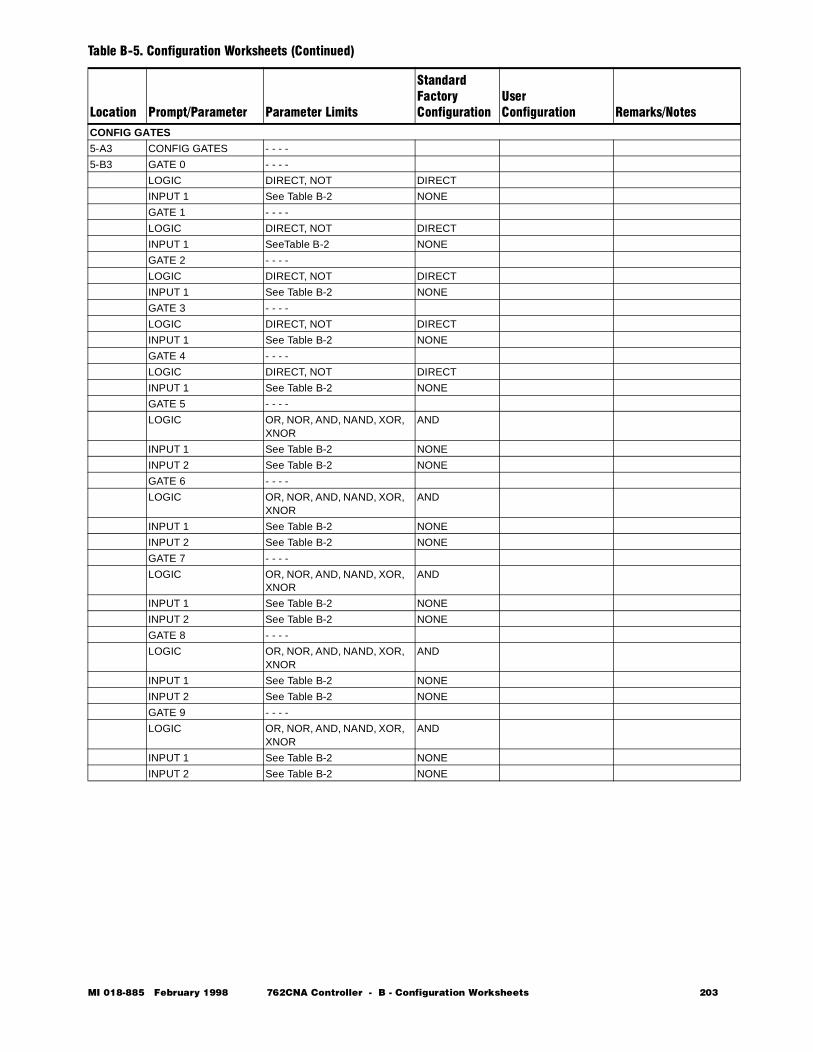
CONFIG GATES
5-A3 CONFIG GATES - - - -
5-B3 GATE 0 - - - -
LOGIC DIRECT, NOT DIRECT
INPUT 1 See Table B-2 NONE
GATE 1 - - - -
LOGIC DIRECT, NOT DIRECT
INPUT 1 SeeTable B-2 NONE
GATE 2 - - - -
LOGIC DIRECT, NOT DIRECT
INPUT 1 See Table B-2 NONE
GATE 3 - - - -
LOGIC DIRECT, NOT DIRECT
INPUT 1 See Table B-2 NONE
GATE 4 - - - -
LOGIC DIRECT, NOT DIRECT
INPUT 1 See Table B-2 NONE
GATE 5 - - - -
LOGIC OR, NOR, AND, NAND, XOR, XNOR
AND
INPUT 1 See Table B-2 NONE
INPUT 2 See Table B-2 NONE
GATE 6 - - - -
LOGIC OR, NOR, AND, NAND, XOR, XNOR
AND
INPUT 1 See Table B-2 NONE
INPUT 2 See Table B-2 NONE
GATE 7 - - - -
LOGIC OR, NOR, AND, NAND, XOR, XNOR
AND
INPUT 1 See Table B-2 NONE
INPUT 2 See Table B-2 NONE
GATE 8 - - - -
LOGIC OR, NOR, AND, NAND, XOR, XNOR
AND
INPUT 1 See Table B-2 NONE
INPUT 2 See Table B-2 NONE
GATE 9 - - - -
LOGIC OR, NOR, AND, NAND, XOR, XNOR
AND
INPUT 1 See Table B-2 NONE
INPUT 2 See Table B-2 NONE
Table B-5. Configuration Worksheets (Continued)
Location Prompt/Parameter Parameter Limits
StandardFactoryConfiguration
UserConfiguration Remarks/Notes
MI 018-885 February 1998 762CNA Controller - B - Configuration Worksheets 203
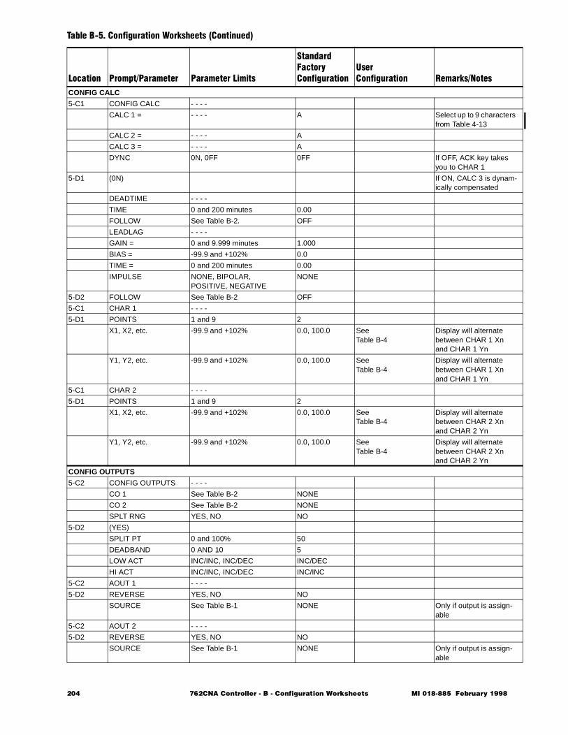
CONFIG CALC
5-C1 CONFIG CALC - - - -
CALC 1 = - - - - A Select up to 9 characters from Table 4-13
CALC 2 = - - - - A
CALC 3 = - - - - A
DYNC 0N, 0FF 0FF If OFF, ACK key takes you to CHAR 1
5-D1 (0N) If ON, CALC 3 is dynam-ically compensated
DEADTIME - - - -
TIME 0 and 200 minutes 0.00
FOLLOW See Table B-2. OFF
LEADLAG - - - -
GAIN = 0 and 9.999 minutes 1.000
BIAS = -99.9 and +102% 0.0
TIME = 0 and 200 minutes 0.00
IMPULSE NONE, BIPOLAR, POSITIVE, NEGATIVE
NONE
5-D2 FOLLOW See Table B-2 OFF
5-C1 CHAR 1 - - - -
5-D1 POINTS 1 and 9 2
X1, X2, etc. -99.9 and +102% 0.0, 100.0 See Table B-4
Display will alternate between CHAR 1 Xn and CHAR 1 Yn
Y1, Y2, etc. -99.9 and +102% 0.0, 100.0 SeeTable B-4
Display will alternate between CHAR 1 Xn and CHAR 1 Yn
5-C1 CHAR 2 - - - -
5-D1 POINTS 1 and 9 2
X1, X2, etc. -99.9 and +102% 0.0, 100.0 See Table B-4
Display will alternate between CHAR 2 Xn and CHAR 2 Yn
Y1, Y2, etc. -99.9 and +102% 0.0, 100.0 See Table B-4
Display will alternate between CHAR 2 Xn and CHAR 2 Yn
CONFIG OUTPUTS
5-C2 CONFIG OUTPUTS - - - -
CO 1 See Table B-2 NONE
CO 2 See Table B-2 NONE
SPLT RNG YES, NO NO
5-D2 (YES)
SPLIT PT 0 and 100% 50
DEADBAND 0 AND 10 5
LOW ACT INC/INC, INC/DEC INC/DEC
HI ACT INC/INC, INC/DEC INC/INC
5-C2 AOUT 1 - - - -
5-D2 REVERSE YES, NO NO
SOURCE See Table B-1 NONE Only if output is assign-able
5-C2 AOUT 2 - - - -
5-D2 REVERSE YES, NO NO
SOURCE See Table B-1 NONE Only if output is assign-able
Table B-5. Configuration Worksheets (Continued)
Location Prompt/Parameter Parameter Limits
StandardFactoryConfiguration
UserConfiguration Remarks/Notes
204 762CNA Controller - B - Configuration Worksheets MI 018-885 February 1998
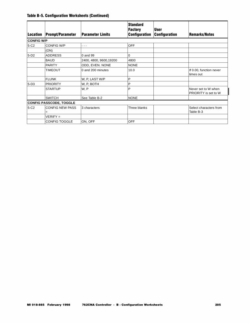
CONFIG W/P
5-C2 CONFIG W/P - - - OFF
(ON)
5-D2 ADDRESS 0 and 99 0
BAUD 2400, 4800, 9600,19200 4800
PARITY ODD, EVEN. NONE NONE
TIMEOUT 0 and 200 minutes 10.0 If 0.00, function never times out
FLUNK W, P, LAST W/P P
5-D3 PRIORITY W, P, BOTH P
STARTUP W, P P Never set to W when PRIORITY is set to W
SWITCH See Table B-2 NONE
CONFIG PASSCODE, TOGGLE
5-C2 CONFIG NEW PASS =
3 characters Three blanks Select characters from Table B-3
VERIFY =
CONFIG TOGGLE ON, OFF OFF
Table B-5. Configuration Worksheets (Continued)
Location Prompt/Parameter Parameter Limits
StandardFactoryConfiguration
UserConfiguration Remarks/Notes
MI 018-885 February 1998 762CNA Controller - B - Configuration Worksheets 205
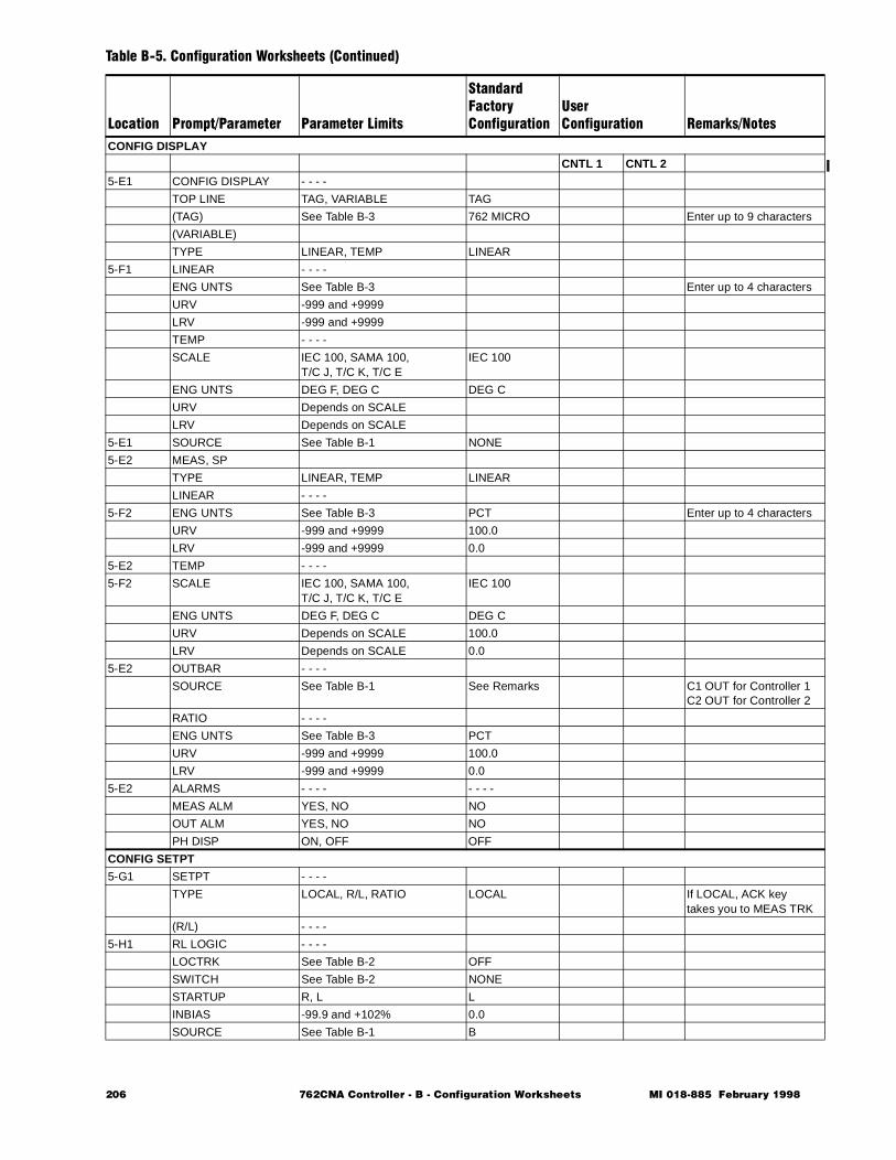
CONFIG DISPLAY
CNTL 1 CNTL 2
5-E1 CONFIG DISPLAY - - - -
TOP LINE TAG, VARIABLE TAG
(TAG) See Table B-3 762 MICRO Enter up to 9 characters
(VARIABLE)
TYPE LINEAR, TEMP LINEAR
5-F1 LINEAR - - - -
ENG UNTS See Table B-3 Enter up to 4 characters
URV -999 and +9999
LRV -999 and +9999
TEMP - - - -
SCALE IEC 100, SAMA 100, T/C J, T/C K, T/C E
IEC 100
ENG UNTS DEG F, DEG C DEG C
URV Depends on SCALE
LRV Depends on SCALE
5-E1 SOURCE See Table B-1 NONE
5-E2 MEAS, SP
TYPE LINEAR, TEMP LINEAR
LINEAR - - - -
5-F2 ENG UNTS See Table B-3 PCT Enter up to 4 characters
URV -999 and +9999 100.0
LRV -999 and +9999 0.0
5-E2 TEMP - - - -
5-F2 SCALE IEC 100, SAMA 100, T/C J, T/C K, T/C E
IEC 100
ENG UNTS DEG F, DEG C DEG C
URV Depends on SCALE 100.0
LRV Depends on SCALE 0.0
5-E2 OUTBAR - - - -
SOURCE See Table B-1 See Remarks C1 OUT for Controller 1C2 OUT for Controller 2
RATIO - - - -
ENG UNTS See Table B-3 PCT
URV -999 and +9999 100.0
LRV -999 and +9999 0.0
5-E2 ALARMS - - - - - - - -
MEAS ALM YES, NO NO
OUT ALM YES, NO NO
PH DISP ON, OFF OFF
CONFIG SETPT
5-G1 SETPT - - - -
TYPE LOCAL, R/L, RATIO LOCAL If LOCAL, ACK key takes you to MEAS TRK
(R/L) - - - -
5-H1 RL LOGIC - - - -
LOCTRK See Table B-2 OFF
SWITCH See Table B-2 NONE
STARTUP R, L L
INBIAS -99.9 and +102% 0.0
SOURCE See Table B-1 B
Table B-5. Configuration Worksheets (Continued)
Location Prompt/Parameter Parameter Limits
StandardFactoryConfiguration
UserConfiguration Remarks/Notes
206 762CNA Controller - B - Configuration Worksheets MI 018-885 February 1998
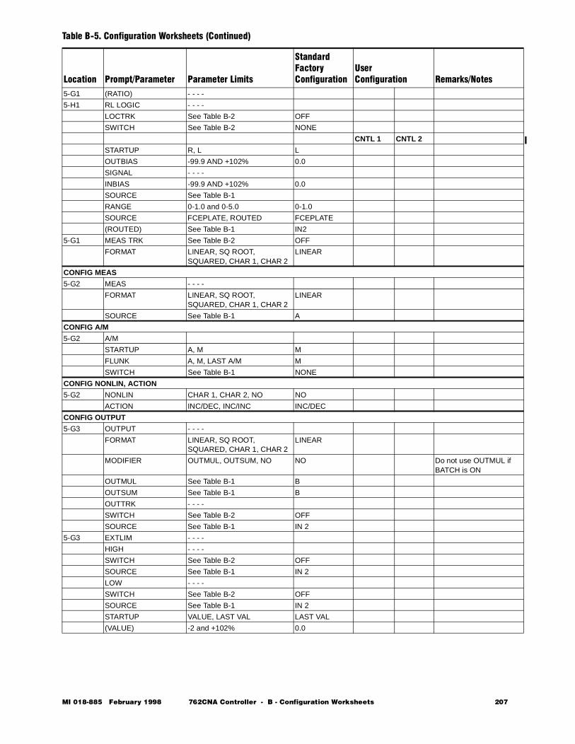
5-G1 (RATIO) - - - -
5-H1 RL LOGIC - - - -
LOCTRK See Table B-2 OFF
SWITCH See Table B-2 NONE
CNTL 1 CNTL 2
STARTUP R, L L
OUTBIAS -99.9 AND +102% 0.0
SIGNAL - - - -
INBIAS -99.9 AND +102% 0.0
SOURCE See Table B-1
RANGE 0-1.0 and 0-5.0 0-1.0
SOURCE FCEPLATE, ROUTED FCEPLATE
(ROUTED) See Table B-1 IN2
5-G1 MEAS TRK See Table B-2 OFF
FORMAT LINEAR, SQ ROOT, SQUARED, CHAR 1, CHAR 2
LINEAR
CONFIG MEAS
5-G2 MEAS - - - -
FORMAT LINEAR, SQ ROOT, SQUARED, CHAR 1, CHAR 2
LINEAR
SOURCE See Table B-1 A
CONFIG A/M
5-G2 A/M
STARTUP A, M M
FLUNK A, M, LAST A/M M
SWITCH See Table B-1 NONE
CONFIG NONLIN, ACTION
5-G2 NONLIN CHAR 1, CHAR 2, NO NO
ACTION INC/DEC, INC/INC INC/DEC
CONFIG OUTPUT
5-G3 OUTPUT - - - -
FORMAT LINEAR, SQ ROOT, SQUARED, CHAR 1, CHAR 2
LINEAR
MODIFIER OUTMUL, OUTSUM, NO NO Do not use OUTMUL if BATCH is ON
OUTMUL See Table B-1 B
OUTSUM See Table B-1 B
OUTTRK - - - -
SWITCH See Table B-2 OFF
SOURCE See Table B-1 IN 2
5-G3 EXTLIM - - - -
HIGH - - - -
SWITCH See Table B-2 OFF
SOURCE See Table B-1 IN 2
LOW - - - -
SWITCH See Table B-2 OFF
SOURCE See Table B-1 IN 2
STARTUP VALUE, LAST VAL LAST VAL
(VALUE) -2 and +102% 0.0
Table B-5. Configuration Worksheets (Continued)
Location Prompt/Parameter Parameter Limits
StandardFactoryConfiguration
UserConfiguration Remarks/Notes
MI 018-885 February 1998 762CNA Controller - B - Configuration Worksheets 207
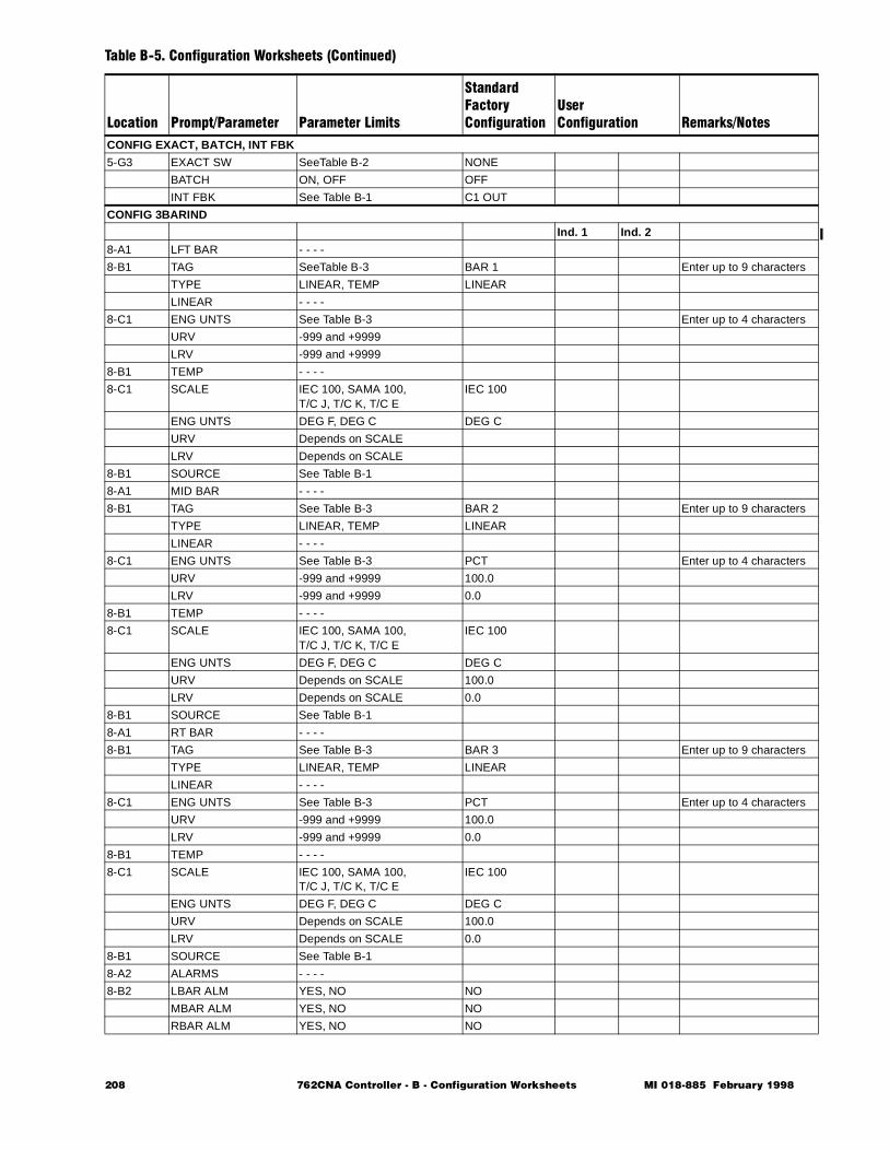
CONFIG EXACT, BATCH, INT FBK
5-G3 EXACT SW SeeTable B-2 NONE
BATCH ON, OFF OFF
INT FBK See Table B-1 C1 OUT
CONFIG 3BARIND
Ind. 1 Ind. 2
8-A1 LFT BAR - - - -
8-B1 TAG SeeTable B-3 BAR 1 Enter up to 9 characters
TYPE LINEAR, TEMP LINEAR
LINEAR - - - -
8-C1 ENG UNTS See Table B-3 Enter up to 4 characters
URV -999 and +9999
LRV -999 and +9999
8-B1 TEMP - - - -
8-C1 SCALE IEC 100, SAMA 100, T/C J, T/C K, T/C E
IEC 100
ENG UNTS DEG F, DEG C DEG C
URV Depends on SCALE
LRV Depends on SCALE
8-B1 SOURCE See Table B-1
8-A1 MID BAR - - - -
8-B1 TAG See Table B-3 BAR 2 Enter up to 9 characters
TYPE LINEAR, TEMP LINEAR
LINEAR - - - -
8-C1 ENG UNTS See Table B-3 PCT Enter up to 4 characters
URV -999 and +9999 100.0
LRV -999 and +9999 0.0
8-B1 TEMP - - - -
8-C1 SCALE IEC 100, SAMA 100, T/C J, T/C K, T/C E
IEC 100
ENG UNTS DEG F, DEG C DEG C
URV Depends on SCALE 100.0
LRV Depends on SCALE 0.0
8-B1 SOURCE See Table B-1
8-A1 RT BAR - - - -
8-B1 TAG See Table B-3 BAR 3 Enter up to 9 characters
TYPE LINEAR, TEMP LINEAR
LINEAR - - - -
8-C1 ENG UNTS See Table B-3 PCT Enter up to 4 characters
URV -999 and +9999 100.0
LRV -999 and +9999 0.0
8-B1 TEMP - - - -
8-C1 SCALE IEC 100, SAMA 100, T/C J, T/C K, T/C E
IEC 100
ENG UNTS DEG F, DEG C DEG C
URV Depends on SCALE 100.0
LRV Depends on SCALE 0.0
8-B1 SOURCE See Table B-1
8-A2 ALARMS - - - -
8-B2 LBAR ALM YES, NO NO
MBAR ALM YES, NO NO
RBAR ALM YES, NO NO
Table B-5. Configuration Worksheets (Continued)
Location Prompt/Parameter Parameter Limits
StandardFactoryConfiguration
UserConfiguration Remarks/Notes
208 762CNA Controller - B - Configuration Worksheets MI 018-885 February 1998
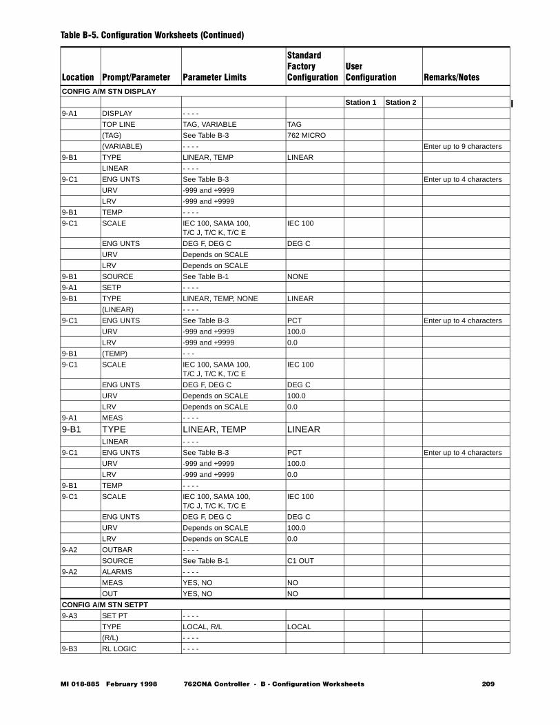
CONFIG A/M STN DISPLAY
Station 1 Station 2
9-A1 DISPLAY - - - -
TOP LINE TAG, VARIABLE TAG
(TAG) See Table B-3 762 MICRO
(VARIABLE) - - - - Enter up to 9 characters
9-B1 TYPE LINEAR, TEMP LINEAR
LINEAR - - - -
9-C1 ENG UNTS See Table B-3 Enter up to 4 characters
URV -999 and +9999
LRV -999 and +9999
9-B1 TEMP - - - -
9-C1 SCALE IEC 100, SAMA 100, T/C J, T/C K, T/C E
IEC 100
ENG UNTS DEG F, DEG C DEG C
URV Depends on SCALE
LRV Depends on SCALE
9-B1 SOURCE See Table B-1 NONE
9-A1 SETP - - - -
9-B1 TYPE LINEAR, TEMP, NONE LINEAR
(LINEAR) - - - -
9-C1 ENG UNTS See Table B-3 PCT Enter up to 4 characters
URV -999 and +9999 100.0
LRV -999 and +9999 0.0
9-B1 (TEMP) - - -
9-C1 SCALE IEC 100, SAMA 100, T/C J, T/C K, T/C E
IEC 100
ENG UNTS DEG F, DEG C DEG C
URV Depends on SCALE 100.0
LRV Depends on SCALE 0.0
9-A1 MEAS - - - -
9-B1 TYPE LINEAR, TEMP LINEARLINEAR - - - -
9-C1 ENG UNTS See Table B-3 PCT Enter up to 4 characters
URV -999 and +9999 100.0
LRV -999 and +9999 0.0
9-B1 TEMP - - - -
9-C1 SCALE IEC 100, SAMA 100, T/C J, T/C K, T/C E
IEC 100
ENG UNTS DEG F, DEG C DEG C
URV Depends on SCALE 100.0
LRV Depends on SCALE 0.0
9-A2 OUTBAR - - - -
SOURCE See Table B-1 C1 OUT
9-A2 ALARMS - - - -
MEAS YES, NO NO
OUT YES, NO NO
CONFIG A/M STN SETPT
9-A3 SET PT - - - -
TYPE LOCAL, R/L LOCAL
(R/L) - - - -
9-B3 RL LOGIC - - - -
Table B-5. Configuration Worksheets (Continued)
Location Prompt/Parameter Parameter Limits
StandardFactoryConfiguration
UserConfiguration Remarks/Notes
MI 018-885 February 1998 762CNA Controller - B - Configuration Worksheets 209
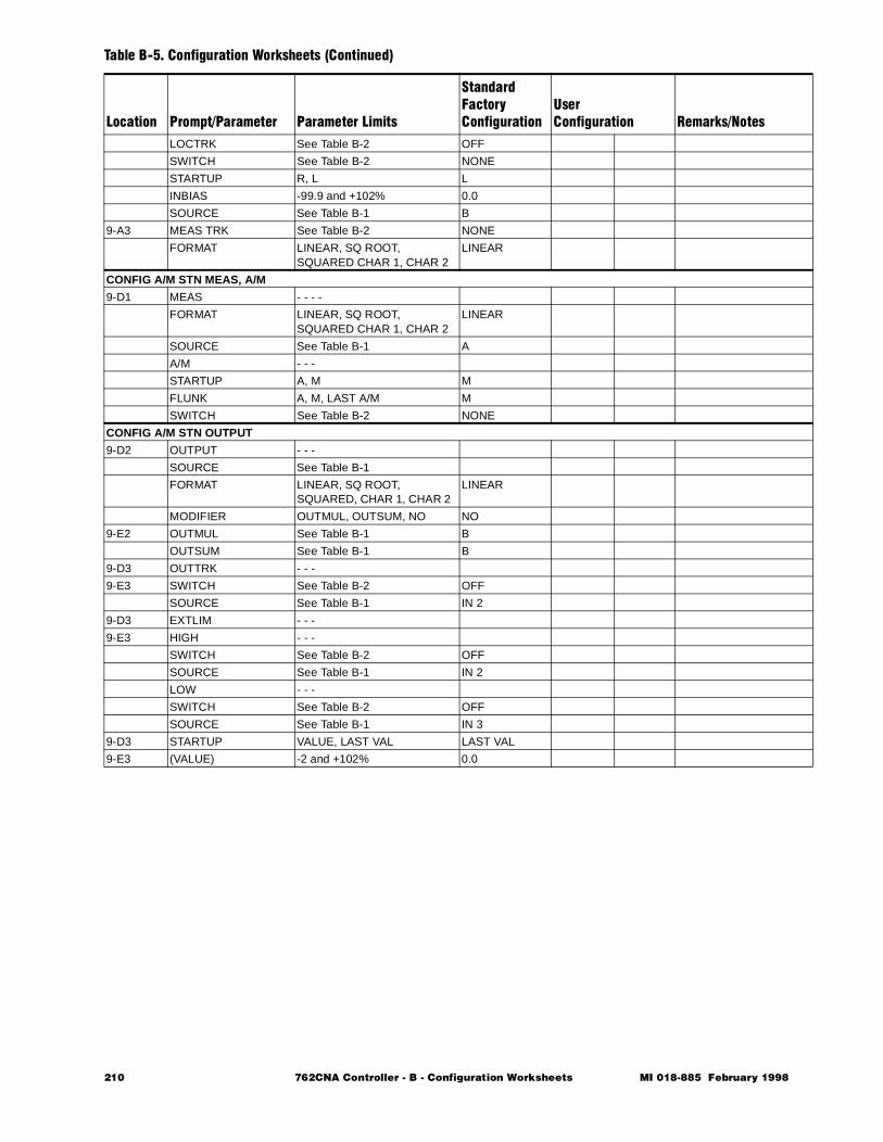
LOCTRK See Table B-2 OFF
SWITCH See Table B-2 NONE
STARTUP R, L L
INBIAS -99.9 and +102% 0.0
SOURCE See Table B-1 B
9-A3 MEAS TRK See Table B-2 NONE
FORMAT LINEAR, SQ ROOT, SQUARED CHAR 1, CHAR 2
LINEAR
CONFIG A/M STN MEAS, A/M
9-D1 MEAS - - - -
FORMAT LINEAR, SQ ROOT, SQUARED CHAR 1, CHAR 2
LINEAR
SOURCE See Table B-1 A
A/M - - -
STARTUP A, M M
FLUNK A, M, LAST A/M M
SWITCH See Table B-2 NONE
CONFIG A/M STN OUTPUT
9-D2 OUTPUT - - -
SOURCE See Table B-1
FORMAT LINEAR, SQ ROOT, SQUARED, CHAR 1, CHAR 2
LINEAR
MODIFIER OUTMUL, OUTSUM, NO NO
9-E2 OUTMUL See Table B-1 B
OUTSUM See Table B-1 B
9-D3 OUTTRK - - -
9-E3 SWITCH See Table B-2 OFF
SOURCE See Table B-1 IN 2
9-D3 EXTLIM - - -
9-E3 HIGH - - -
SWITCH See Table B-2 OFF
SOURCE See Table B-1 IN 2
LOW - - -
SWITCH See Table B-2 OFF
SOURCE See Table B-1 IN 3
9-D3 STARTUP VALUE, LAST VAL LAST VAL
9-E3 (VALUE) -2 and +102% 0.0
Table B-5. Configuration Worksheets (Continued)
Location Prompt/Parameter Parameter Limits
StandardFactoryConfiguration
UserConfiguration Remarks/Notes
210 762CNA Controller - B - Configuration Worksheets MI 018-885 February 1998
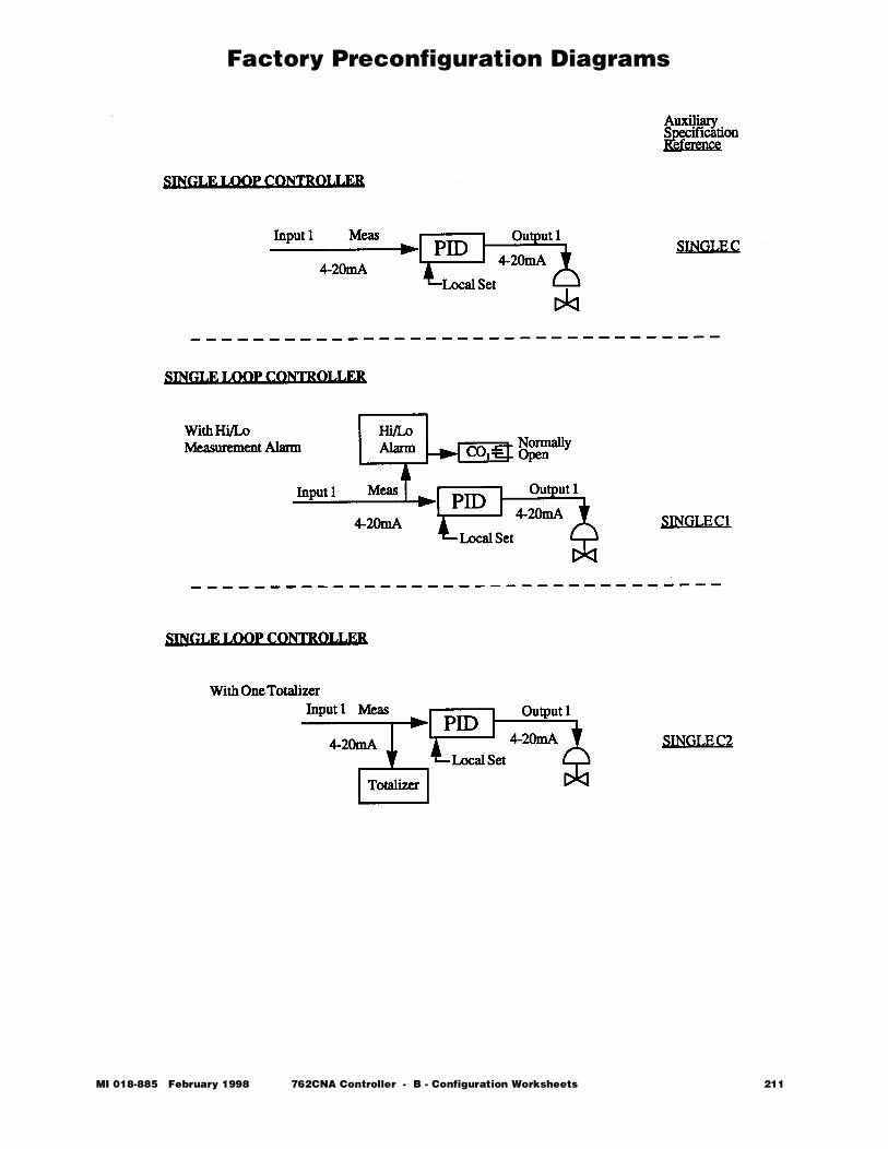
Factory Preconfiguration Diagrams
MI 018-885 February 1998 762CNA Controller - B - Configuration Worksheets 211
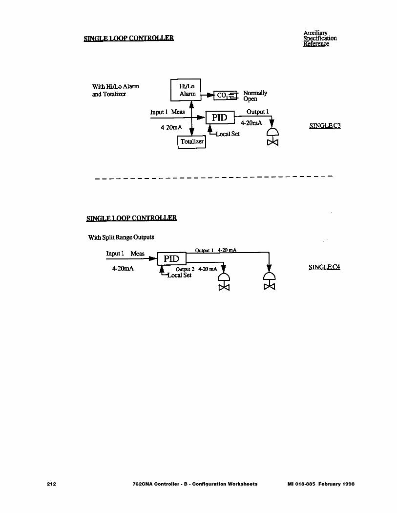
212 762CNA Controller - B - Configuration Worksheets MI 018-885 February 1998
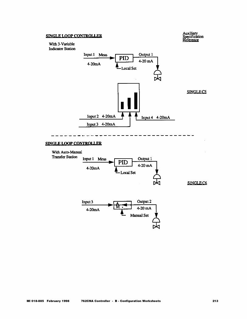
MI 018-885 February 1998 762CNA Controller - B - Configuration Worksheets 213
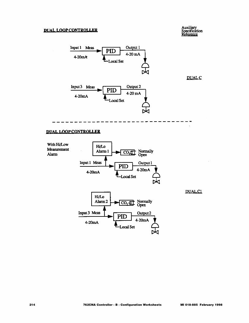
214 762CNA Controller - B - Configuration Worksheets MI 018-885 February 1998
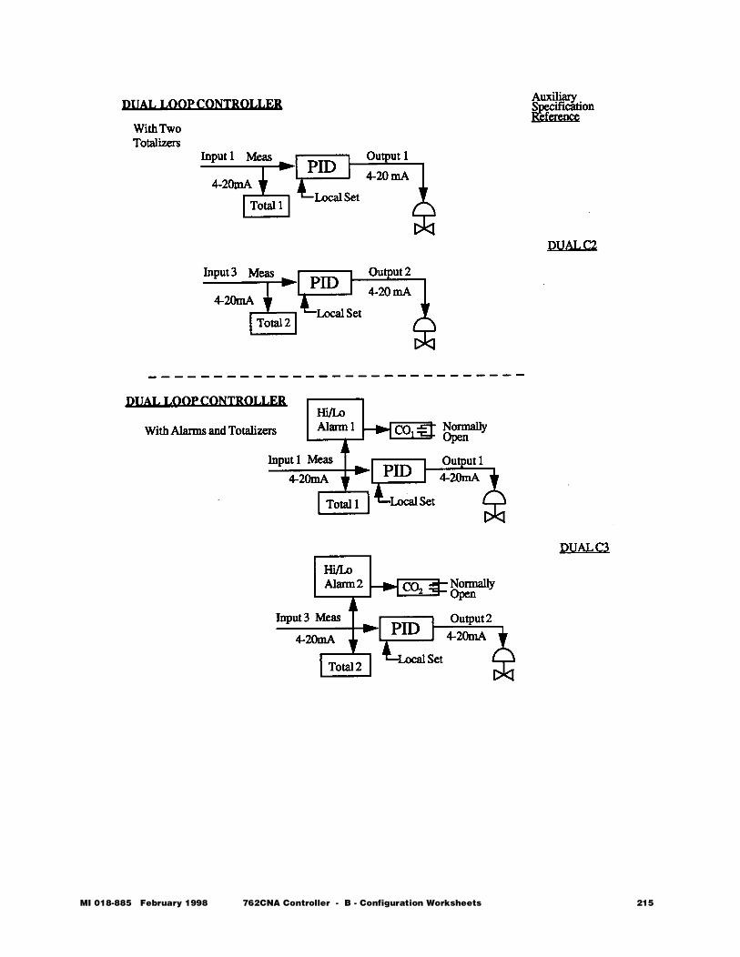
MI 018-885 February 1998 762CNA Controller - B - Configuration Worksheets 215
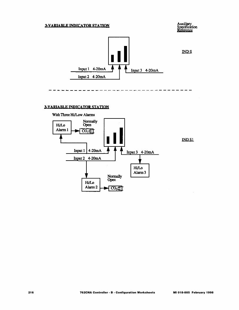
216 762CNA Controller - B - Configuration Worksheets MI 018-885 February 1998
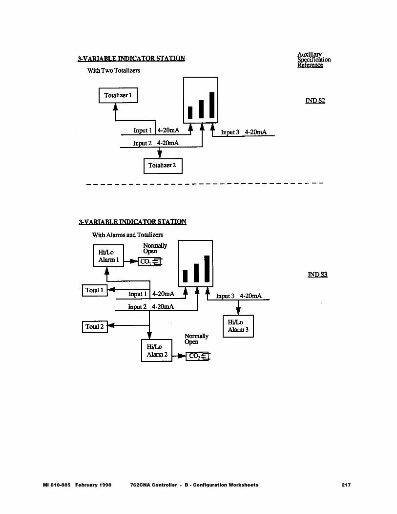
MI 018-885 February 1998 762CNA Controller - B - Configuration Worksheets 217
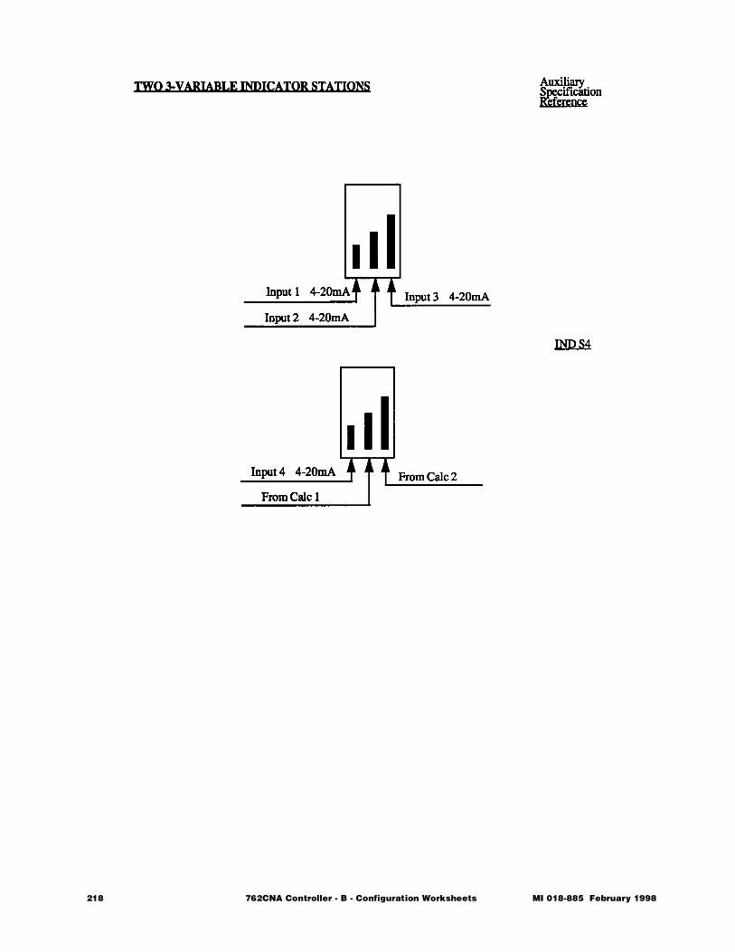
218 762CNA Controller - B - Configuration Worksheets MI 018-885 February 1998
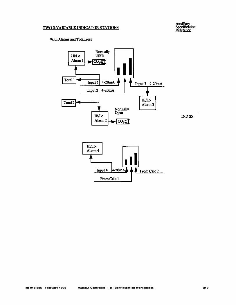
MI 018-885 February 1998 762CNA Controller - B - Configuration Worksheets 219
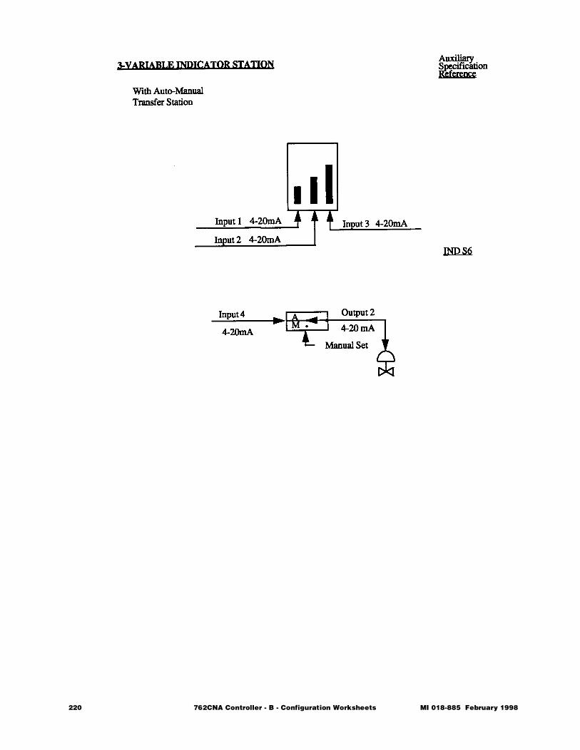
220 762CNA Controller - B - Configuration Worksheets MI 018-885 February 1998
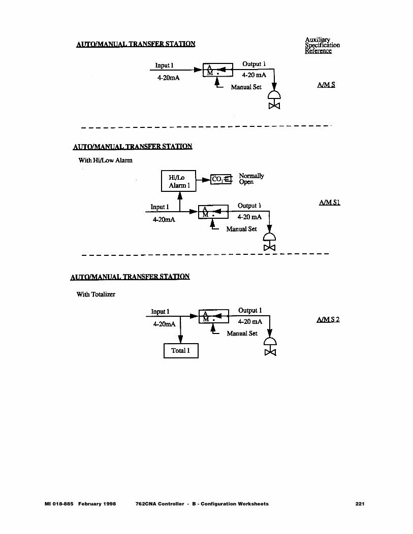
MI 018-885 February 1998 762CNA Controller - B - Configuration Worksheets 221
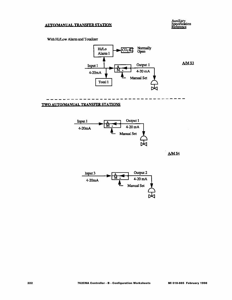
222 762CNA Controller - B - Configuration Worksheets MI 018-885 February 1998
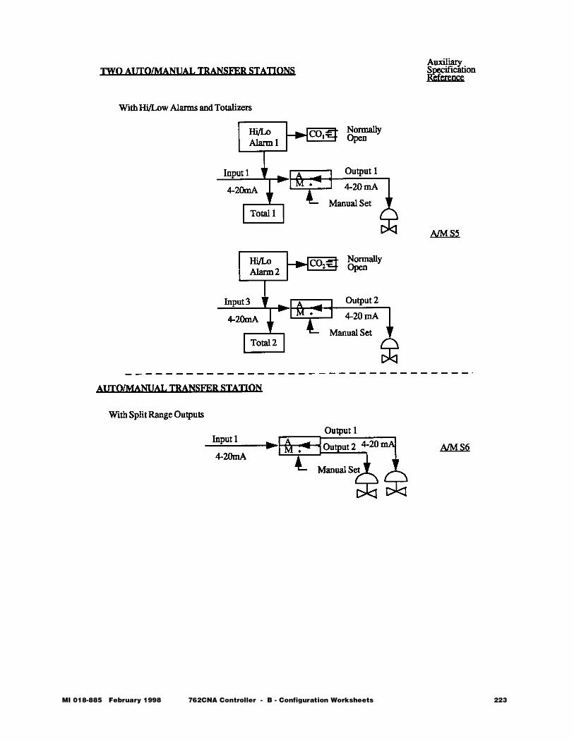
MI 018-885 February 1998 762CNA Controller - B - Configuration Worksheets 223
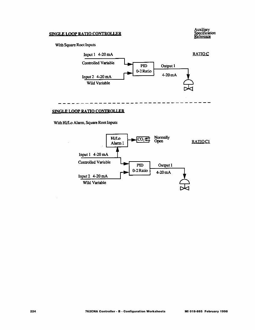
224 762CNA Controller - B - Configuration Worksheets MI 018-885 February 1998
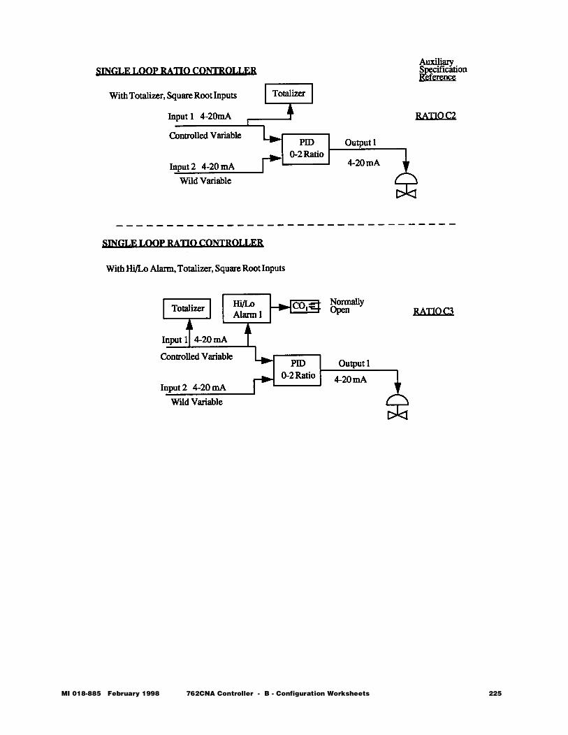
MI 018-885 February 1998 762CNA Controller - B - Configuration Worksheets 225
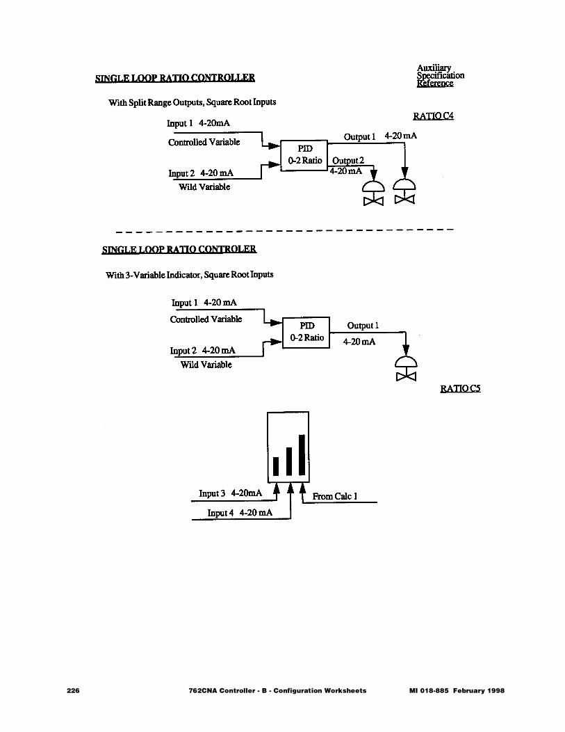
226 762CNA Controller - B - Configuration Worksheets MI 018-885 February 1998
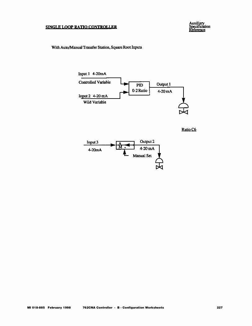
MI 018-885 February 1998 762CNA Controller - B - Configuration Worksheets 227

228 762CNA Controller - B - Configuration Worksheets MI 018-885 February 1998
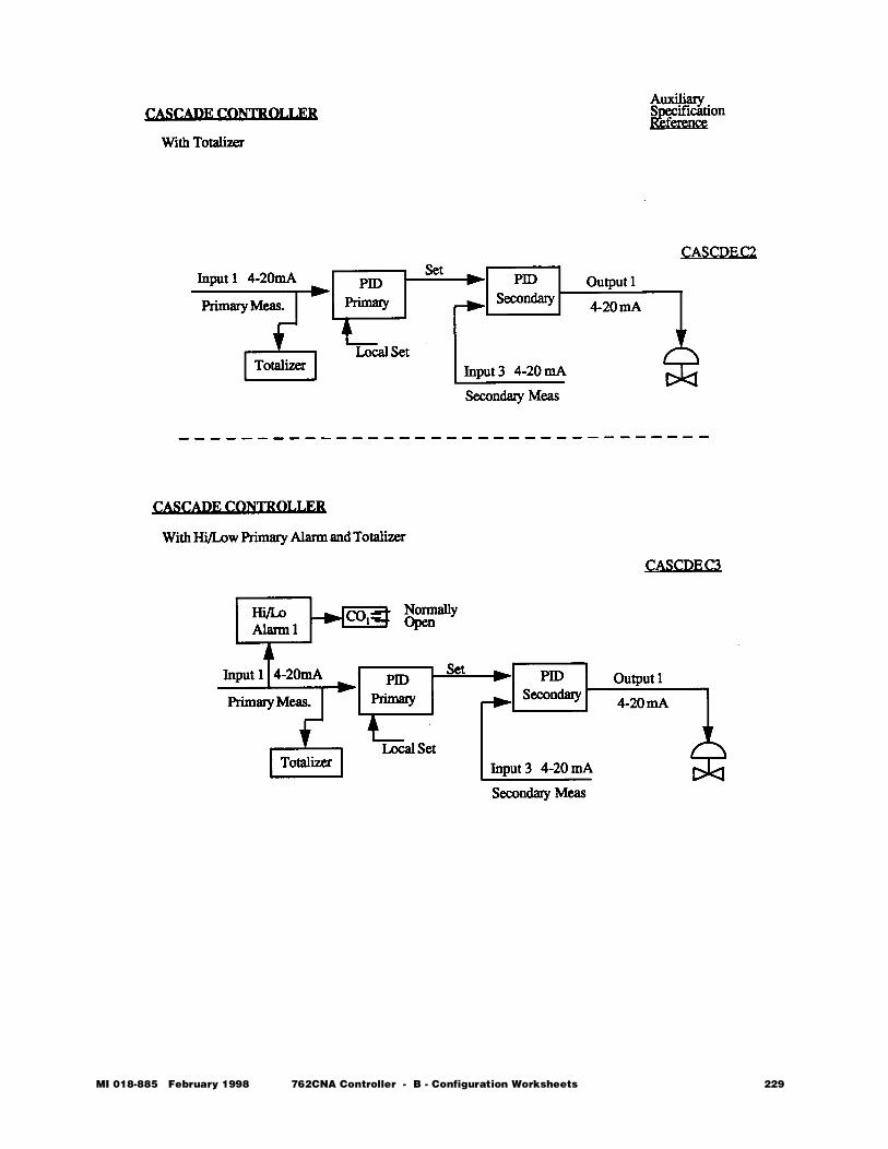
MI 018-885 February 1998 762CNA Controller - B - Configuration Worksheets 229
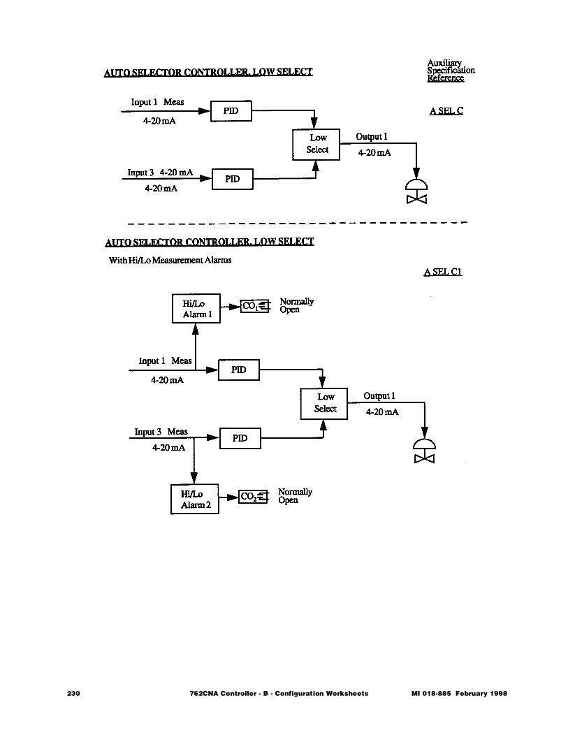
230 762CNA Controller - B - Configuration Worksheets MI 018-885 February 1998
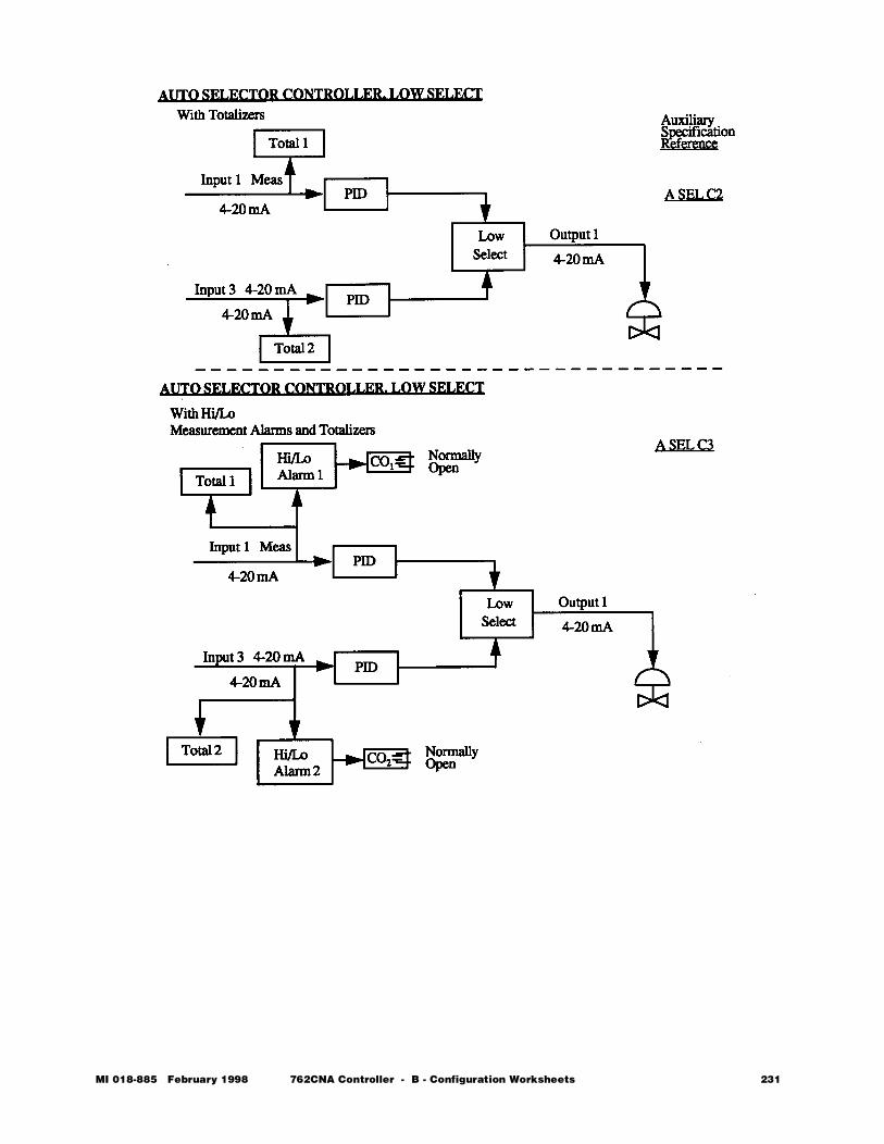
MI 018-885 February 1998 762CNA Controller - B - Configuration Worksheets 231
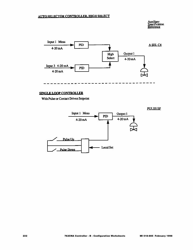
232 762CNA Controller - B - Configuration Worksheets MI 018-885 February 1998
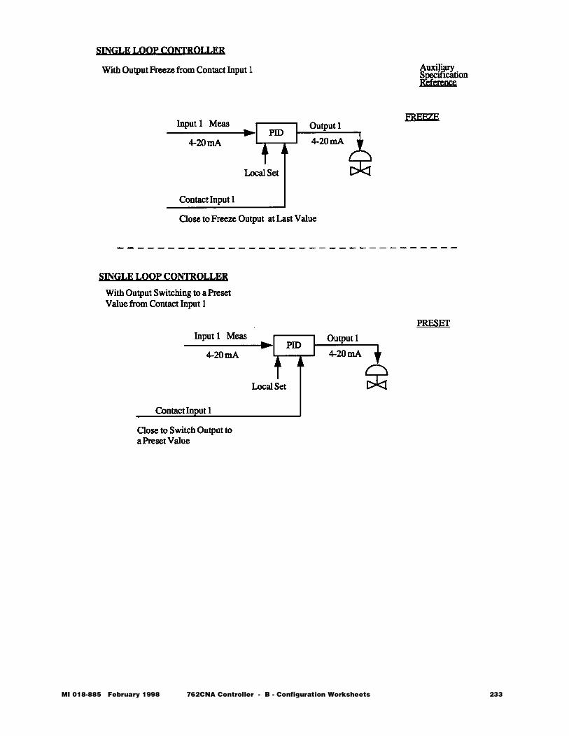
MI 018-885 February 1998 762CNA Controller - B - Configuration Worksheets 233

234 762CNA Controller - B - Configuration Worksheets MI 018-885 February 1998

762C SINGLESTATION
MICROController
February 1998
Preface • xiii Chapter 1 Quick Check • 1 Chapter 2 Product Overview • 11 Chapter 3 Installation • 23 Chapter 4 Configuration • 49 Chapter 5 Operation • 109 Chapter 6 EXACT Tuning • 135 Chapter 7 Calibration, Troubleshooting,
Maintenance • 159 Appendix A Specifications • 183 Appendix B Configuration Worksheets • 193
Ð Appendix C Structure Diagrams • 237 Appendix D Parts List • 247 Appendix E Dimensional Print • 255 Appendix F Functional Diagram • 261 Glossary • 267 Index • 287
The Intelligent Automation People

236 762CNA Controller MI 018-885 February 1998
MI 018-885 Februar
C Structure Diagrams
This appendix contains the structure diagrams for the 762C Controller. By following this appendix, you can locate the parameter you wish to read or change.• Access to the structure from Normal Operation is achieved by pressing
the TAG key. This brings you to the first item in the structure, READ.• The ∆ and ∇ keys move you vertically within a connected group of param-
eters in the diagram.• The ACK key moves you horizontally through a group of parameters and
then on to the next group.• The SEL key moves you back through the diagram in minor increments.
At various points in the diagrams you will find arrows and numbered bal-loons. These direct you to subsequent pages in the diagram. Also, some sec-tions are marked with an asterisk (*) with a note to repeat for a similar entry. This is done to keep the diagrams as brief as possible. Throughout the text of Chapter 4, Configuration and in Appendix B, Con-figuration Worksheets, you will find location designators (e.g., 5-B2). These direct you to the parameter you are looking for in the diagram. In the exam-ple given, the 5 refers to the diagram beginning with Balloon number 5 in the upper left hand corner (Structure Diagram 5). The designation B2 refers to map coordinates on that page. Therefore, a reference to configure ALARM 1 is 5-B2.
y 1998 762CNA Controller - C - Structure Diagrams 237
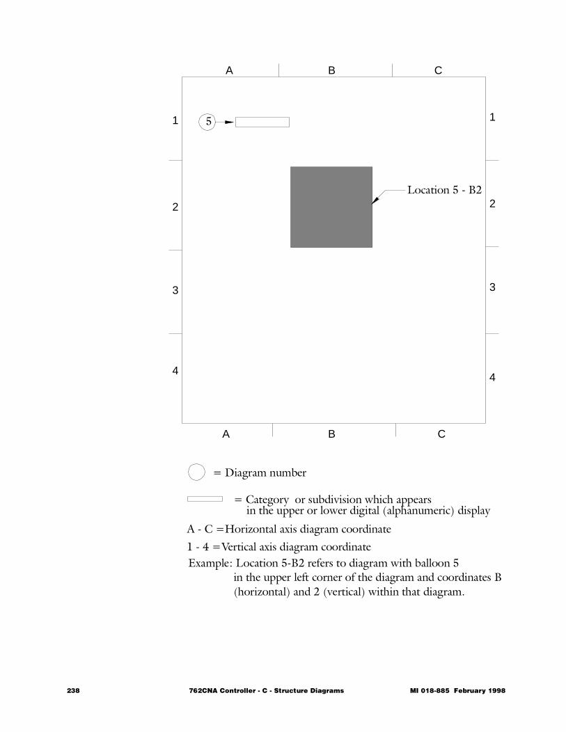
A B C
A B C
1
2
3
4
1
2
3
4
5
= Diagram number
= Category or subdivision which appears in the upper or lower digital (alphanumeric) display
A - C =Horizontal axis diagram coordinate1 - 4 =Vertical axis diagram coordinate Example: Location 5-B2 refers to diagram with balloon 5
in the upper left corner of the diagram and coordinates B(horizontal) and 2 (vertical) within that diagram.
Location 5 - B2
238 762CNA Controller - C - Structure Diagrams MI 018-885 February 1998
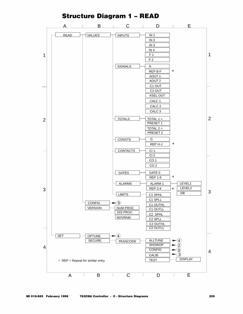
Structure Diagram 1 – READ
READ VALUES
TOTALS TOTAL 1 =PRESET 1
TOTAL 2 =PRESET 2
INPUTS
IN 4
F 1
F 2
A
REP B-F
AOUT 1
AOUT 2
C1 OUT
CALC 2
CALC 3
SIGNALS
CONSTS G
REP H-J
CONTACTS
CO 1
CO 2
GATES GATE 0
REP 1-9
ALARMS ALARM 1 LEVEL1
LEVEL2
DB
REP 2-4
A B C D E
LIMITS
C2 SPLL
C2 OUTLL
SET OPTUNESECURE PASSCODE ALLTUNE
SHOWOP
CONFIG
DISPLAY
VERSION
CONFIG
NUM PROCDIS PROC
NOVRAM
*
*
*
*
* REP = Repeat for similar entry
33
44
11
2 2
A B C D E
IN 1
IN 2
IN 3
CI 1CI 2
C1 SPHL
C1 SPLL
C1 OUTHLC1 OUTLL
C2 SPHL
TEST
C2 OUTHL
CALIB
C2 OUT
CALC 1
5
44253
ASEL OUT
MI 018-885 February 1998 762CNA Controller - C - Structure Diagrams 239
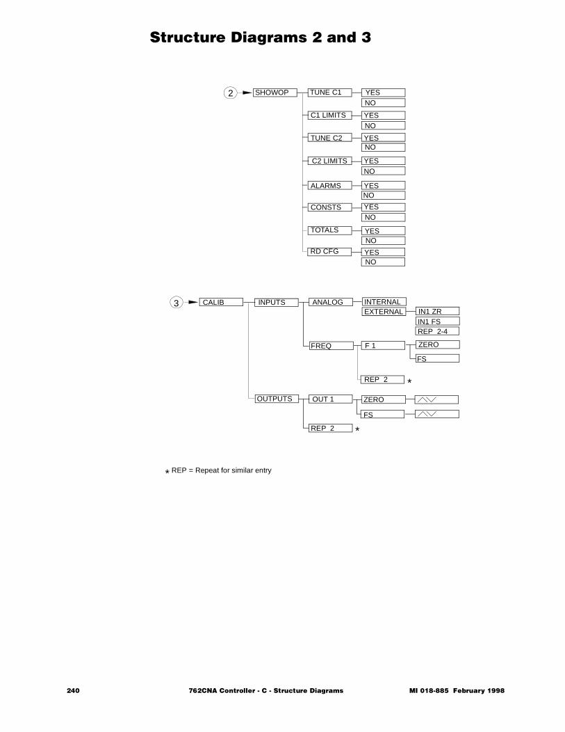
Structure Diagrams 2 and 3
SHOWOP TUNE C1
C1 LIMITS
TUNE C2
C2 LIMITS
ALARMS
CONSTS
TOTALS
YESNO
YESNO
YESNO
YESNO
YESNO
YESNO
YESNO
CALIB INPUTS
OUTPUTS
ANALOG
FREQ
OUT 1
REP 2
INTERNALEXTERNAL
F 1
FS
ZERO
IN1 ZRIN1 FSREP 2-4
ZERO
FS
REP 2
*
*
* REP = Repeat for similar entry
RD CFG YESNO
2
3
240 762CNA Controller - C - Structure Diagrams MI 018-885 February 1998
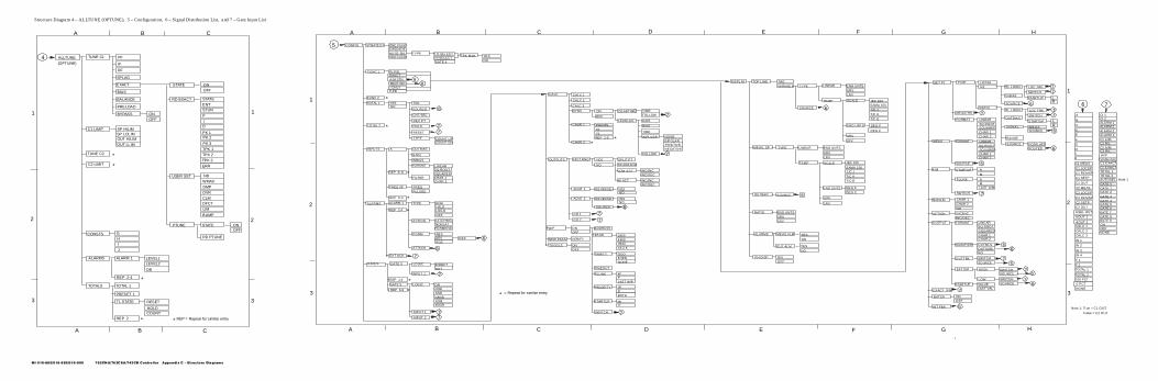
MI 018-885/018-889/018-900 762CN A/762CSA/743CB Controller Appendix C - Structure Diagrams
Structure Diagram 4 – ALLTUNE (OPTUNE), 5 – Configuration, 6 – Signal Distribution List, and 7 – Gate Input List
ALLTUNE TUNE C1 PF
IF
DF
SPLAG
EXACT STATE
BIAS
BALANCE
PRELOAD
BYPASS
C1 LIMIT SP HILIMSP LOLIMOUT HILIM
OUT LLIM
RD EXACT
USER SET
PTUNE
TUNE C2
C2 LIMIT
CONSTS G
HI
J
ALARMS ALARM 1
REP 2-4
LEVEL1LEVEL2
DB
STATE ONOFF
TOTALS
NB
WMAX
DMP
OVR
CLMDFCT
LIM
BUMP
ONOFF
STATE
ENTSTUN
P
ID
PK 1PK 2
PK 3
TPK 1
TPK 2
TPK 3
ERR
TOTAL 1
PRESET 1
T1 STATE
HOLDCOUNT
REP 2
*
*
**
2
3
2
3
A B C
A B
11
4(OPTUNE)
REP = Repeat for similar entry
*
RESET
RD PTUNE
ONOFF
REP E-F
PULSED
ALARMS ALARM 1
REP 2-4
EXT ACK
TYPE
ACTION
FORM
ATTACH
HI/HI
LO/LOOFF
LATCHINGNONLATPERMISVE
ABSDEVROC
REF
1
2
3
*
*
*
* = Repeat for similar entry
GATES GATE 0
REP 1-4
GATE 5
REP 6-9
LOGIC
INPUT 1
LOGIC DIRECTNOT
ORNORANDNANDXORXNOR
CALC CALC 1
CALC 2
CALC 3
DYNC ON
OFF
DEADTIME
LEADLAG
INPUT 1
INPUT 2
TIMEFOLLOW
GAIN
BIAS
TIME
IMPULSE
FOLLOW
NONEBIPOLARPOSITIVENEGATIVE
OUTPUTS
CO 1
CO 2
SPLT RNG
AOUT 2
YES
NO
SPLIT PT
LOW ACT
HI ACT
INC/INCINC/DEC
INC/DECINC/INC
W/P
NEW PASS
TOGGLE
ONOFF
ONOFF
VERIFY
ADDRESS
BAUD
PARITY
TIMEOUT
FLUNK
PRIORITY
STARTUP
SWITCH
24004800960019.2 K
ODDEVENNONE
WPLAST W/P
WPBOTH
WP
*
*
DEADBAND
CHAR 1
CHAR 2
POINTSX1Y1REP 2-9 *
*
DISPLAY TOP LINE TAGVARIABLE TYPE
SOURCE
LINEAR
TEMP
ENG UNTSURVLRV
SCALE IEC 100SAMA 100T/C JT/C KT/C E
DEG C
DEG FENG UNTS
URV
LRV
MEAS, SP TYPE LINEAR
TEMP
ENG UNTS
URVLRV
SCALE IEC 100
SAMA 100T/C JT/C KT/C E
ENG UNTS
URV
LRV
DEG FDEG C
OUTBAR SOURCE
RATIO ENG UNTSURVLRV
PH DISP ONOFF
ALARMS MEAS ALM
OUT ALM
YESNO
YES
NO
FUNC 2
CONFIG STRATEGY
FUNC 1
INPUTS
TOTAL 2
CASCADE
EXACT
P,PD
TOTAL 1NO
3BAR IND
FREQ
CHAR 1CHAR 2
SQUARED
TWO FUNC TRK MAN
YES
LO SELECT
ONE FUNC
PI,PID
TAG
CNT/SEC
RESET
COUNT UP
NO
AUTO SEL TYPEHI SELECT
A/M STN
HOLD
GATE 4
A
REP B-D
FREQ I/P
INBIAS
FILTER
LINEAR
I ONLY
YES
GAIN
FORMATSQ ROOT
SOURCE
DEC PT
TYPECOUNT DN
OUTBIAS
RATIO
SOURCE FCEPLATEROUTED
SET PT TYPE LOCALR/L RL LOGIC
INBIAS
SOURCE
SWITCH
STARTUP
MEASTRK
FORMAT LINEARSQ ROOTSQUAREDCHAR 1CHAR 2
MEAS FORMAT LINEARSQ ROOTSQUAREDCHAR 1CHAR 2
SOURCE
A/M STARTUP A
M
FLUNK AMLAST A/M
SW ITCH
NONLIN
ACTION
CHAR 1CHAR 2NO
INC/INC
INC/DECOUTPUT FORMAT
MODIFIER
OUTTRK
EXTLIM
EXACT SW
BATCH
INT FBK
LINEARSQ ROOTSQUAREDCHAR 1CHAR 2
OUTMULOUTSUMNO
SWITCHSOURCE
HIGH
LOW
SWITCHSOURCE
SWITCHSOURCESTARTUP VALUE
LAST VAL
ONOFF
A B
LOC TRK
RL LOGIC
RL
SW ITCH
STARTUP
LOC TRK
RL
INBIASSIGNALSOURCE
RANGE
OUTBIASA
B
C
DE
F
G
HIJ
C1 MEAS
C1 LOCSP
C1 REMSPC1 SETP
C1 OUT
C2 MEAS
C2 LOCSP
C2 REMSP
C2 SETPC2 OUT
AOUT 1
AOUT 2CALC 1
CALC 2CALC 3
IN 1
IN 2
IN 3IN 4
F 1
F 2TOTAL 1
TOTAL 2
CI 1CI 2ALARM 1ALARM 2ALARM 3ALARM 4C1 A/MC1 R/LC2 A/MC2 R/LW/P
COMM FAIL
C2 EXACTC1 EXACT
TOTAL 1TOTAL 2AUTOSEL GATE 0GATE 1GATE 2GATE 3GATE 4GATE 5GATE 6GATE 7GATE 8GATE 9ONOFFNONE
5
*
*
6
6
7
77
7
6
6
77
6777
6
6
6
7
66
76
76
76
7
6
Note 1
100 PCT0 PCTNONE
Note 1: True = C1 OUT;
98
6
77
7
REVERSE YESNO
SOURCE
A B C D E F G H
1
2
3
HGFEDCBA
6 7
False = C2 OUT
C
HI/LO
ASEL OUT7
7
6
7
7
AOUT 1 REVERSE YESNO

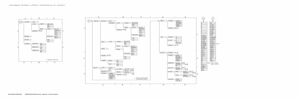
MI 018-885/018-889/018-900 762CN A/762CSA/743CB Controller Appendix C - Structure Diagrams
Structure Diagram 8 – 3-Bar Indicator, 9 – A/M Station, 6 – Signal Distribution List, and 7 – Gate Input List
DISPLAY TOP LINE TAG
VARIABLE TYPE LINEAR
TEMP
ENG UNTSURVLRV
SCALE IEC 100SAMA 100
T/C JT/C KT/C E
ENG UNTS
URV
LRV
DEG FDEG C
SETP
MEAS
ALARMS MEAS
OUT
YES
NO
YESNO
OUTBAR
*
* = Same as for SETP except
SOURCE
SET PT TYPE LOCALR/L
MEASTRK
FORMAT LINEARSQ ROOT
SQUAREDCHAR 1CHAR 2
MEAS FORMAT LINEAR
SQ ROOTSQUAREDCHAR 1CHAR 2
A/M
SOURCE
STARTUP A
M
FLUNK A
MLAST A/M
SWITCH
OUTPUT
FORMAT LINEARSQ ROOTSQUARED
CHAR 1CHAR 2
MODIFIER OUTMULOUTSUMNO
OUTTRK SWITCHSOURCE
EXTLIM HIGH
LOW
SWITCHSOURCE
SWITCHSOURCE
STARTUP VALUE
LAST VAL
RL LOGIC
INBIAS
SOURCE
SWITCH
STARTUP
LOC TRK
RL
SOURCE
89
6
6
7
7
7
6
7
6
66
76
76
7
6
AB
CDEFGHIJC1 MEASC1 LOCSPC1 REMSPC1 SETP
C1 OUTC2 MEASC2 LOCSPC2 REMSPC2 SETPC2 OUT
AOUT 1AOUT 2CALC 1
CALC 2CALC 3IN 1
IN 2IN 3IN 4
F 1F 2TOTAL 1
TOTAL 2
Note 1: True = C1 OUT;
CI 1CI 2ALARM 1ALARM 2
ALARM 3ALARM 4C1 A/MC1 R/LC2 A/MC2 R/LW/P
COMM FAIL
C2 EXACTC1 EXACT
TOTAL 1TOTAL 2AUTOSEL GATE 0GATE 1GATE 2
GATE 3GATE 4GATE 5GATE 6GATE 7GATE 8GATE 9ONOFFNONE
Note 1
6
6 7
NONE
100 PCT0 PCT
1
2
3
1
2
3
A B C D E
D ECBA
False = C2 OUT
LFT BAR
MID BAR
RT BAR
TAG
TYPE
SOURCE
LINEAR
TEMP
ENG UNTS
URVLRV
SCALE IEC 100
SAMA 100T/C JT/C KT/C E
ENG UNTS
URV
LRV
DEG FDEG C
ALARMS LBAR ALM
MBAR ALM
RBAR ALM
YESNO
YESNO
YESNO
*
*
2 2
A B C
11
* = Repeat for similar entry
A B C
6
ASEL OUT
TYPE LINEAR
TEMP
ENG UNTSURVLRV
SCALE IEC 100SAMA 100
T/C JT/C KT/C E
ENG UNTS
URV
LRV
DEG FDEG C
NONE
no type selection NONE


762C SINGLESTATION
MICROController
February 1998
Preface • xiii Chapter 1 Quick Check • 1 Chapter 2 Product Overview • 11 Chapter 3 Installation • 23 Chapter 4 Configuration • 49 Chapter 5 Operation • 109 Chapter 6 EXACT Tuning • 135 Chapter 7 Calibration, Troubleshooting,
Maintenance • 159 Appendix A Specifications • 183 Appendix B Configuration Worksheets • 193 Appendix C Structure Diagrams • 237
Ð Appendix D Parts List • 247 Appendix E Dimensional Print • 255 Appendix F Functional Diagram • 261 Glossary • 267 Index • 287
The Intelligent Automation People

246 762CNA Controller MI 018-885 February 1998

MI 018-885 Februar
D Parts List
NOTE Information in this Parts List is based on PL 009-136 dated 12/94.
762CNA SINGLE STATION MICRO Controller with Integral Power Supply Style AA*, DIN Panel Mounted
Model Code
NOTE To order parts, call Foxboro at 800-343-1198. (In Massachusetts, call 800-322-2322.)
* The second letter in the style is the firmware style.
762CNA = SINGLE STATION MICRO Controller, DIN Panel-Mounted with Integral Power Supply
Voltage–A = 120 V ac, 50/60 Hz–B = 220 V ac, 50/60 Hz–C = 240 V ac, 50/60 Hz–D = 24 V dc–E = 24 V ac, 50/60 Hz–J = 100 V ac, 50/60 Hz
HousingT = Terminal Block on Rear of HousingW = Controller Chassis Without Housing
Optional–1 = Output Isolation–2 = RTD Input
y 1998 762CNA Controller - D - Parts List 247
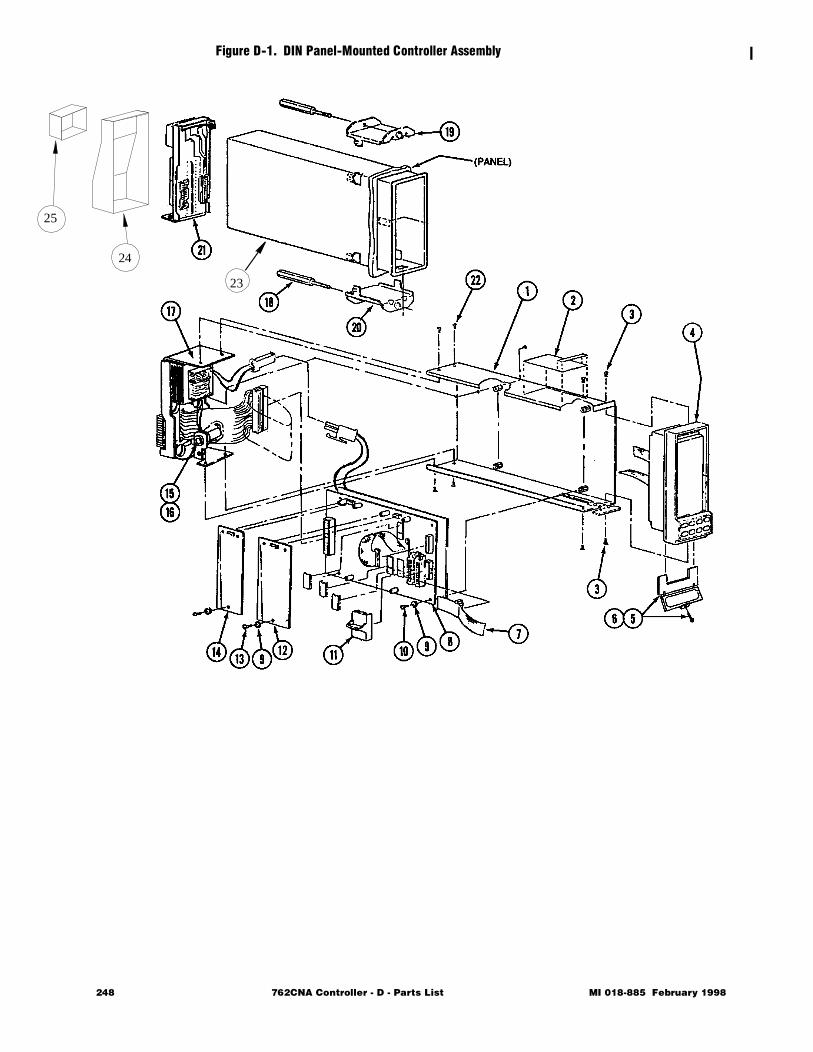
25
Figure D-1. DIN Panel-Mounted Controller Assembly
23
24
248 762CNA Controller - D - Parts List MI 018-885 February 1998
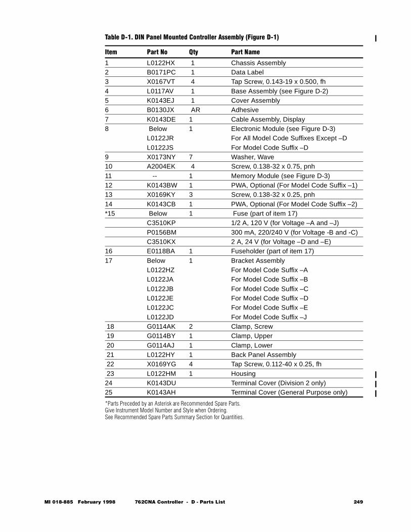
*Parts Preceded by an Asterisk are Recommended Spare Parts.Give Instrument Model Number and Style when Ordering.See Recommended Spare Parts Summary Section for Quantities.
Table D-1. DIN Panel Mounted Controller Assembly (Figure D-1)
Item Part No Qty Part Name
1 L0122HX 1 Chassis Assembly2 B0171PC 1 Data Label3 X0167VT 4 Tap Screw, 0.143-19 x 0.500, fh4 L0117AV 1 Base Assembly (see Figure D-2)5 K0143EJ 1 Cover Assembly6 B0130JX AR Adhesive7 K0143DE 1 Cable Assembly, Display8 Below 1 Electronic Module (see Figure D-3)
L0122JR For All Model Code Suffixes Except –DL0122JS For Model Code Suffix –D
9 X0173NY 7 Washer, Wave10 A2004EK 4 Screw, 0.138-32 x 0.75, pnh11 -- 1 Memory Module (see Figure D-3)12 K0143BW 1 PWA, Optional (For Model Code Suffix –1)13 X0169KY 3 Screw, 0.138-32 x 0.25, pnh14 K0143CB 1 PWA, Optional (For Model Code Suffix –2)*15 Below 1 Fuse (part of item 17)
C3510KP 1/2 A, 120 V (for Voltage –A and –J)P0156BM 300 mA, 220/240 V (for Voltage -B and -C)C3510KX 2 A, 24 V (for Voltage –D and –E)
16 E0118BA 1 Fuseholder (part of item 17)17 Below 1 Bracket Assembly
L0122HZ For Model Code Suffix –AL0122JA For Model Code Suffix –BL0122JB For Model Code Suffix –CL0122JE For Model Code Suffix –DL0122JC For Model Code Suffix –EL0122JD For Model Code Suffix –J
18 G0114AK 2 Clamp, Screw 19 G0114BY 1 Clamp, Upper 20 G0114AJ 1 Clamp, Lower 21 L0122HY 1 Back Panel Assembly 22 X0169YG 4 Tap Screw, 0.112-40 x 0.25, fh 23 L0122HM 1 Housing24 K0143DU Terminal Cover (Division 2 only)25 K0143AH Terminal Cover (General Purpose only)
MI 018-885 February 1998 762CNA Controller - D - Parts List 249
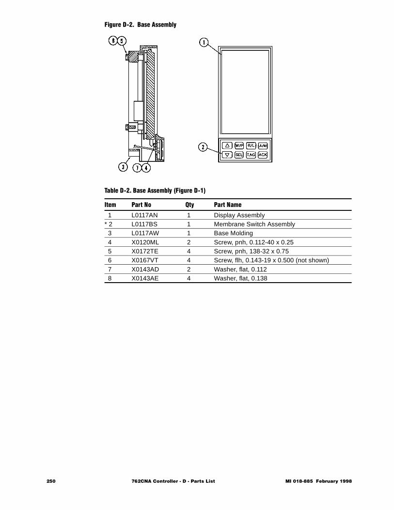
Figure D-2. Base Assembly
Table D-2. Base Assembly (Figure D-1)
Item Part No Qty Part Name
1 L0117AN 1 Display Assembly* 2 L0117BS 1 Membrane Switch Assembly 3 L0117AW 1 Base Molding 4 X0120ML 2 Screw, pnh, 0.112-40 x 0.25 5 X0172TE 4 Screw, pnh, 138-32 x 0.75 6 X0167VT 4 Screw, flh, 0.143-19 x 0.500 (not shown) 7 X0143AD 2 Washer, flat, 0.112 8 X0143AE 4 Washer, flat, 0.138
250 762CNA Controller - D - Parts List MI 018-885 February 1998
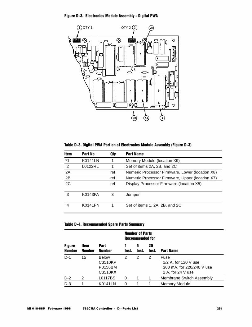
Figure D-3. Electronics Module Assembly - Digital PWA
Table D-3. Digital PWA Portion of Electronics Module Assembly (Figure D-3)
Item Part No Qty Part Name
*1 K0141LN 1 Memory Module (location X9) 2 L0122RL 1 Set of items 2A, 2B, and 2C 2A ref Numeric Processor Firmware, Lower (location X8) 2B ref Numeric Processor Firmware, Upper (location X7) 2C ref Display Processor Firmware (location X5)
3 K0143FA 3 Jumper
4 K0141FN 1 Set of items 1, 2A, 2B, and 2C
Table D-4. Recommended Spare Parts Summary
FigureNumber
ItemNumber
PartNumber
Number of Parts Recommended for
Part Name1Inst.
5Inst.
20Inst.
D-1 15 BelowC3510KPP0156BMC3510KX
2 2 2 Fuse 1/2 A, for 120 V use 300 mA, for 220/240 V use 2 A, for 24 V use
D-2 2 L0117BS 0 1 1 Membrane Switch AssemblyD-3 1 K0141LN 0 1 1 Memory Module
QTY 1 QTY 2
MI 018-885 February 1998 762CNA Controller - D - Parts List 251

252 762CNA Controller - D - Parts List MI 018-885 February 1998

762C SINGLESTATION
MICROController
February 1998
Preface • xiii Chapter 1 Quick Check • 1 Chapter 2 Product Overview • 11 Chapter 3 Installation • 23 Chapter 4 Configuration • 49 Chapter 5 Operation • 109 Chapter 6 EXACT Tuning • 135 Chapter 7 Calibration, Troubleshooting,
Maintenance • 159 Appendix A Specifications • 183 Appendix B Configuration Worksheets • 193 Appendix C Structure Diagrams • 237 Appendix D Parts List • 247
Ð Appendix E Dimensional Print • 255 Appendix F Functional Diagram • 261 Glossary • 267 Index • 287
The Intelligent Automation People

254 762CNA Controller MI 018-885 February 1998

MI 018-885 Februar
E Dimensional Print
NOTE Information in this appendix is based on DP 018-836 dated 10/94.
y 1998 762CNA Controller - E - 255
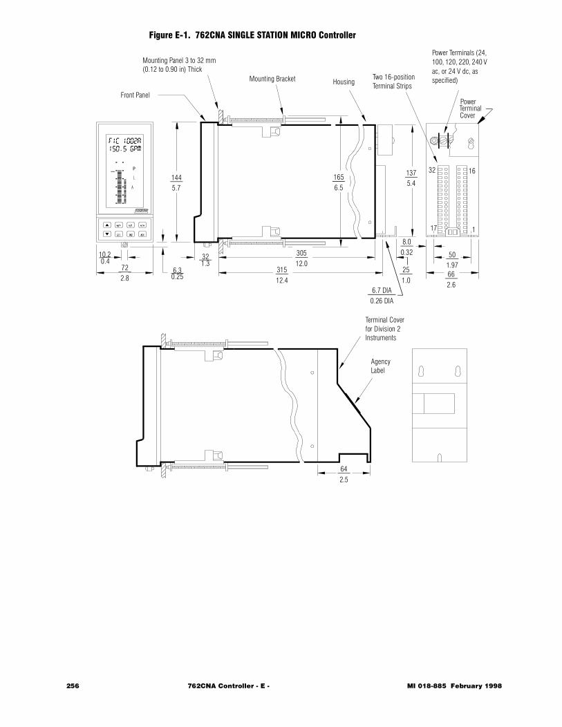
Figure E-1. 762CNA SINGLE STATION MICRO Controller
Mounting Panel 3 to 32 mm(0.12 to 0.90 in) Thick
Mounting Bracket HousingTwo 16-position Terminal Strips
Power Terminals (24, 100, 120, 220, 240 V ac, or 24 V dc, as specified)
Front Panel
TerminalCover
10.20.4
722.8
6.30.25
321.3
1445.7
1656.5
1375.4
30512.0
31512.4
6.7 DIA0.26 DIA
251.0
8.00.32 50
1.97662.6
642.5
Terminal Coverfor Division 2Instruments
AgencyLabel
17
32 16
1
Power
256 762CNA Controller - E - MI 018-885 February 1998
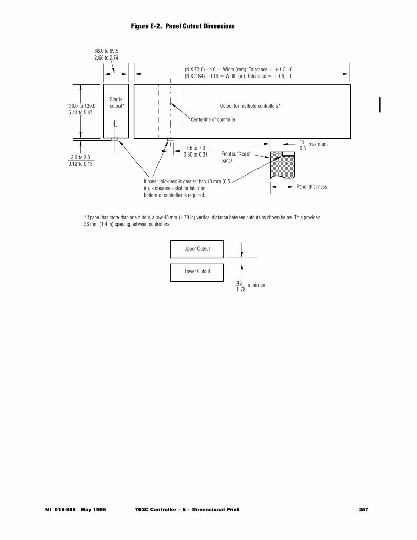
Figure E-2. Panel Cutout Dimensions
(N X 72.0) - 4.0 = Width (mm); Tolerance = +1.5, -0(N X 2.84) - 0.16 = Width (in); Tolerance = +.06, -0
68.0 to 69.52.68 to 2.74
138.0 to 139.05.43 to 5.47
Front surface of panel
If panel thickness is greater than 13 mm (0.5 in), a clearance slot for latch on bottom of controller is required.
130.5
maximum
Panel thickness
Cutout for multiple controllers*
Centerline of controller
7.6 to 7.90.30 to 0.31
Singlecutout*
3.0 to 3.30.12 to 0.13
c
*If panel has more than one cutout, allow 45 mm (1.78 in) vertical distance between cutouts as shown below. This provides 36 mm (1.4 in) spacing between controllers.
Upper Cutout
Lower Cutout
451.78
minimum
MI 018-885 May 1995 762C Controller – E - Dimensional Print 257

258 762CNA Controller - E - MI 018-885 February 1998

762C SINGLESTATION
MICROController
February 1998
Preface • xiii Chapter 1 Quick Check • 1 Chapter 2 Product Overview • 11 Chapter 3 Installation • 23 Chapter 4 Configuration • 49 Chapter 5 Operation • 109 Chapter 6 EXACT Tuning • 135 Chapter 7 Calibration, Troubleshooting,
Maintenance • 159 Appendix A Specifications • 183 Appendix B Configuration Worksheets • 193 Appendix C Structure Diagrams • 237 Appendix D Parts List • 247 Appendix E Dimensional Print • 255
Ð Appendix F Functional Diagram • 261 Glossary • 267 Index • 287
The Intelligent Automation People

260 762CNA Controller MI 018-885 February 1998

MI 018-885 Februar
F Functional Diagram
y 1998 762CNA Controller - F - Functional Diagram 261

262 762CNA Controller - F - Functional Diagram MI 018-885 February 1998
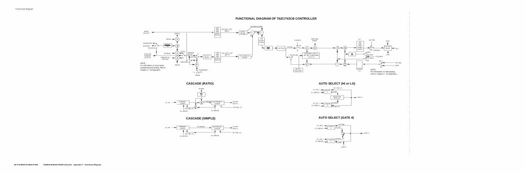
MI 018-885/018-889/018-900 762CN A/762CSA/743CB Controller Appendix F - Functional Diagram
Functional Diagram
SIG.DIST. LISTMEAS
SIG. DIST. L ISTSET PT
RANGE100
+
x
+
+
+
SET PT LIMITS
LINSQRSQD
CHAR1CHAR2
LINSQRSQD
CHAR1CHAR2
MEASSOURCE SIGNAL
INBIAS
FACEPLATE
ROUTED
CASCADEPRIMARYOUTPUT
OUTBIASRATIO
REMOTE SP SOURCE
INBIAS
MEASTRK
LOCTRK
R
L
+INCREMENT
CASCADE
REMOTE SET PT
NONE
NOTE: For information on input signal conditioning and scaling, refer to Chapter 4 – Configuration.
DERIVFILTER
SP LEAD/LAG FILTER
LINCHAR1CHAR2
100P ACTION + +
BATCH PRELOAD
INTEGRAL LAG (T)PD, AM: T=BALANCE
I, PID: T=I
+
PRETUNE BUMP
FILTERED DERIV
ERROR
PD,PIDAM
I
PID,PD,AMI
++
SOURCE
+ x
1100
LINSQRSQD
CHAR1CHAR2
OUTPUTLIMITS
OUTTRK
MANUAL100%
OUTMUL
OUTSUM
0%
SOURCELLIM
HLIM
OUTA
M
F( )
F( )INVERSE
PID, I
PD
INT FBK
BIAS
NOTE: For information on split ranging, refer to Chapter 4 – Configuration..
FUNCTIONAL DIAGRAM OF 762C/743CB CONTROLLER
x SECONDARY CONTR
1100
CASCADE (RATIO)
SIGNAL
C2 REMSPPRIMARY CONTR
INT FBK, C1
C1, MEAS1 C2, MEAS2
C1, SPC2 OUTAOUT 1
SECONDARY CONTR
CASCADE (SIMPLE)
C2 REMSPPRIMARY CONTR
INT FBK, C1
C1, MEAS1 C2, MEAS2
C1, SPC2 OUTAOUT 1
INT FBK, C2
INT FBK, C2
CONTR 1
C1, SP1
C1, MEAS1
INT FBK, C1
C1 OUT
AOUT 1
C2 OUT
INT FBK, C2
C2, SP2
C2, MEAS2CONTR
2
AUTO SELECT (HI or LO)
SELECTORHI or LO
CONTR 1
C1, SP1
C1, MEAS1
INT FBK
C1 OUT
1
0AOUT 1
C2 OUT
INT FBK
C2, SP2C2, MEAS2
CONTR 2
GATE 4
AUTO SELECT (GATE 4)


762C SINGLESTATION
MICROController
February 1998
Preface • xiii Chapter 1 Quick Check • 1 Chapter 2 Product Overview • 11 Chapter 3 Installation • 23 Chapter 4 Configuration • 49 Chapter 5 Operation • 109 Chapter 6 EXACT Tuning • 135 Chapter 7 Calibration, Troubleshooting,
Maintenance • 159 Appendix A Specifications • 183 Appendix B Configuration Worksheets • 193 Appendix C Structure Diagrams • 237 Appendix D Parts List • 247 Appendix E Dimensional Print • 255 Appendix F Functional Diagram • 261
Ð Glossary • 267 Index • 287
The Intelligent Automation People

266 762CNA Controller MI 018-885 February 1998
MI 018-885 Februar
G Glossary
This Glossary contains words that may appear on your display. Most are configuration parameters. However, messages related to EXACT control and those that indicate a problem with your controller are also included.
A A
IN 1 after signal conditioning, gain, and biases have been applied.
ABS
ABSolute alarm.
ACTION
OUTPUT INCreases with INCreasing measurement; OUTPUT INCreases with DECreasing measurement.
ACTION
LATCHING, NON LATching, or PERMISVE alarms.
ADDRESS
Device number (0 to 99) on serial communication port. A total of 30 can be used.
ALARM n
Alarm number 1 through 4.
ALARMS
CONFIGuration, tuning values (ALLTUNE), and DISPLAYing values of up to four alarms.
ALLTUNE
Sets values of TUNE, LIMITS, CONSTS, ALARMS, and TOTALS.
A/M
Auto/Manual.
A/M STN
Specifies Auto/Manual Station function in CONFIGuration.
y 1998 762CNA Controller - G - Glossary 267
Analog
Specifies an ANALOG CALIBration INPUT.
AND
AND gate.
AOUT 1, AOUT 2
Analog Output 1 or 2.
AUTOSEL
Logic output of Auto Selector; True = C1 OUT, False = C2 OUT.
ATTACH
Specifies signals from Signal Distribution List that will activate alarms.
AUTO SEL
Specifies the STRATEGY of using the controller as an AUTO SELector.
B B
IN 2 after signal conditioning, gain, and biases have been applied.
BALANCE
Time function used in P/PD controller.
BATCH
BATCH action function.
BAUD
Data transfer speed between host and controller.
BIAS
Output BIAS for P/PD controller.
BIPOLAR
In dynamic compensation (DYNC), a lead/lag (LLAG) IMPULSE that is both POSITIVE and NEGATIVE.
BOTH
Allows either the workstation or the panel to switch controller operation from W to P or vice versa.
BUMP
Parameter in EXACT configuration.
BYPASS
Routes the set point directly to the output, thus bypassing the control algo-rithm.
C C
IN 3 after signal conditioning, gain, and biases been applied.
Cn A/M
Auto/Manual function of Controller 1 or 2.
Cn EXACT
EXACT function of Controller 1 or 2.
268 762CNA Controller - G - Glossary MI 018-885 February 1998
Cn LIMITS
Protects access to set point and output LIMITS in SHOWOP.
Cn LOCSP
Local Set point of Controller 1 or 2.
Cn MEAS
Measurement signal of Controller 1 or 2.
Cn OUT
Output signal of Controller 1 or 2.
Cn OUTHL
Parameter to READ VALUE of High Output Limit of Controller 1 or 2.
Cn OUTLL
Parameter to READ VALUE of Low Output Limit of Controller 1 or 2.
Cn R/L
Remote/Local function of Controller 1 or 2.
Cn REMSP
Remote Set point of Controller 1 or 2.
Cn SETP
Active Set point of Controller 1 or 2.
Cn SPHL
Parameter to READ VALUE of High Set Point Limit of Controller 1 or 2.
Cn SPLL
Parameter to READ VALUE of Low Set Point Limit of Controller 1 or 2.
CALC, CALC n
Up to three CALCulations on a number of inputs to the controller.
CALIB
Allows CALIBration of controller.
CASCADE
Specifies the STRATEGY of using the controller as a CASCADE controller.
CHAR n
Up to 9-point (8-segment) CHARacterization of signal.
CI 1, CI 2
Contact Input 1 and 2.
CLM
Change Limit in EXACT configuration.
CNT/SEC
In totalizer, counts per second at 100% totalizing rate.
CO 1, CO 2
Contact Output 1 and 2.
MI 018-885 February 1998 762CNA Controller - G - Glossary 269
COMM FAIL
Logic signal in Gate Input List generated by serial communication failure.
CONFIG
Allows entering of controller CONFIGuration.
CONSTS
Constants G through J.
CONTACTS
Parameter to READ VALUE of contact inputs and outputs.
COUNT
Specifies STATE of Totalizer as Counting.
COUNT UP, DN
Specifies TYPE of Totalizer action, counting up or down from preset value.
D D
Derivative in EXACT configuration.
D
IN 4 after signal conditioning, gain, and biases have been applied.
DB
Deadband of alarms and split range.
DEADBAND
Deadband of split range.
DEADTIME
DEADTIME in Dynamic Compensation (DYNC).
DEC PT
Specifies DECimal PoinT position in the Totalizer display.
DEG C
Temperature in Celsius degrees.
DEG F
Temperature in Fahrenheit degrees.
DEV
DEViation alarm.
DF
Faceplate derivative value in ALLTUNE configuration.
DFCT
Derivative Factor in EXACT configuration.
DIRECT
Gate output is same as input.
DIS PROC
Identifies VERSION of the DISplay PROCessor firmware.
270 762CNA Controller - G - Glossary MI 018-885 February 1998
DISPLAY
Allows configuration of information that is to be presented on controller faceplate.
DMP
Maximum allowed damping in EXACT configuration.
DYNC
Dynamic Compensation consisting of DEADTIME, LEADLAG, and IMPULSE.
E E
F 1 after signal conditioning, gain, and biases have been applied.
ENG UNTS
Engineering Units.
ENT
Reason for particular action taken in EXACT tuning.
ENT - 1 PEAK
Message - only one significant (with respect to noise band) peak was found. Measurement is approximately critically damped.
ENT = 2 PEAKS
Message - two peaks found. If peaks are significant, response period is used to adjust proportional and derivative actions.
ENT = 3 PEAKS
Message - 3 peaks found. If peaks are significant, response period is used to adjust proportional and derivative actions.
ENT = DAMPED
Message - error signal (measurement deviation from set point) was over-damped. Response may appear overdamped if WMAX is set too low. If so, algorithm will tighten control settings. This can lead to instability.
ENT = SUSPECT
Message - error signal has suspicious shape that may be caused by multiple disturbances. P, I, and/or D were slightly adjusted based on this suspicious shape.
ENT = FAST
Message - error signal response occurred faster than expected, based on WMAX time. No corrective action was taken.
ENT = SP CHANGE
Message - a large set point change occurred after algorithm had located or verified a peak. Additional corrective action did not occur because algo-rithm went immediately into SETTLE (waiting for next peak) state.
ENT = OOR
Message - error signal was observed but P, I, and/or D were not changed because process was out of control range.
MI 018-885 February 1998 762CNA Controller - G - Glossary 271
ENT = CLAMPED
Message - algorithm attempted to change P and I to values larger than set-ting of PF and IF modified by CLM.
ENT = INIT
EXACT algorithm has been initialized.
ERR
Error parameter in EXACT configuration.
EVEN
EVEN PARITY.
EXACT
EXpert Adaptive Controller Tuning.
EXACT SW
Specifies an event from the Gate Input List to activate EXACT tuning.
EXIT PASS
Enables passage from below to above the PASSCODE when TOGGLE fea-ture is configured.
EXT ACK
Allows specification from Gate Input List of a parameter to EXTernally ACKnowledge an alarm.
EXTERNAL
Specifies EXTERNAL ANALOG INPUT in CALIBration.
EXTLIM
EXTernal LIMits of OUTPUT.
F F
F2 after signal conditioning, gain, and biases have been applied.
F1, F2
Frequency (pulse) inputs 1 and 2.
FCEPLATE
Panel faceplate as applied to mechanism to select source of ratio.
FILTER
FILTER time that can be applied to each input.
FLUNK
Loss of serial communication between controller and host to produce a specified action (in W of W/P mode).
FOLLOW
Switch used in Dynamic Compensation to bypass Deadtime and Leadlag functions.
FORM
ABSolute, DEViation, or Rate Of Change alarms.
272 762CNA Controller - G - Glossary MI 018-885 February 1998
FORMAT
Signal conditioning (LINEAR, SQUARED, SQ ROOT, CHAR).
FREQ
Specifies FREQuency for Calibration.
FREQ
FREQuency inputs as opposed to a pair of pulse up/pulse down inputs.
FREQ I/P
Two FREQuency or one pulse up/pulse down pair of inputs.
FS
Implements Full Scale CALIBration when FREQuency INPUT is used.
FUNC n
In CONFIGuration, specifies FUNCtion 1 or 2 of the instrument. Available functions include various controller types, A/M Station, and 3-Bar Indica-tor.
G G
One of four constants.
GAIN
Gain as applied to inputs and lead/lag function of dynamic compensation.
GATES, GATE n
Boolean GATE 0 through 9.
H H
One of four constants.
HI ACT
In HIgh (above split point) end of SPLIT RaNGe, specifies whether output increases with increasing or decreasing measurement.
HI SELECT
SELECTion of the HIgher output when using auto selector control.
HI/HI
High-High alarm.
HI/LO
High-Low alarm.
HOLD
Specifies an event from the Gate Input List to HOLD (disable) the Total-izer.
I I
Integral in EXACT configuration.
I
One of four constants.
I ONLY
Integral only controller.
MI 018-885 February 1998 762CNA Controller - G - Glossary 273
IEC 100
RTD using IEC 100 curve.
IF
Faceplate integral value in ALLTUNE configuration.
IMPULSE
A function of LEADLAG in Dynamic Compensation.
IN n
Analog INput 1 through INput 4.
IN BIAS
Bias functionally applied before GAIN on inputs. (Configured after GAIN). Also, bias applied to set point.
INC/DEC
Output INCreases with DECreasing measurement.
INC/INC
Output INCreases with INCreasing measurement.
INPUTS
Four analog and two frequency inputs.
INPUT n
Input to Boolean gate.
INTERNAL
Specifies INTERNAL ANALOG INPUT in CALIBration.
INT FBK
INTegral FeedBacK.
J J
One of four constants.
L L
Specifies Local control upon STARTUP after a power failure.
LAST A/M
Last status of A/M before serial communication was lost.
LAST W/P
Last status of W/P before serial communication was lost.
LAST VAL
The LAST VALue of the output before a power loss.
LATCHING
LATCHING alarm action.
LBAR ALM
Specifies display of Left BAR ALarM limits on a 3-Bar Indicator for SOURCE signal alarmed.
274 762CNA Controller - G - Glossary MI 018-885 February 1998
LEADLAG
Lead/lag in Dynamic Compensation (DYNC).
LEVEL 1
LEVEL 1 alarm value in ALLTUNE (or OPTUNE).
LEVEL 2
LEVEL 2 alarm value in ALLTUNE (or OPTUNE).
LFT BAR
LeFT BARgraph in a 3-Bar Indicator.
LIM
Output Cycling LIMit in EXACT configuration.
LIMITS
Parameter to READ set point and output LIMITS.
LINEAR
Linear variable in TOP LINE, MEAS SP, or 3 Bar Indicator display.
LINEAR
LINEAR conditioning; repeats input.
LO SELECT
SELECTion of the LOwer output when using auto selector control.
LOCAL
Provides configuration of LOCAL Set Point.
LOC TRK
Causes local set point to track remote set point.
LOGIC
Defines logic gate Boolean type.
LO/LO
Low-low alarm.
LOW
LOW EXTernal output LIMits.
LOW ACT
In Low end (below split point) of SPLIT RaNGe, specifies whether output increases with increasing or decreasing measurement.
LRV
Lower Range Value.
M MBAR ALM
Specifies display of Middle BAR ALarM limits on a 3-Bar Indicator for SOURCE signal alarmed.
MEAS
Provides access to signal conditioning and SOURCE of controllerMEASurement.
MI 018-885 February 1998 762CNA Controller - G - Glossary 275
MEAS
DiSPlay of the MEASurement in Auto/Manual Station.
MEAS ALM
Specifies display of the MEASurement ALarM.
MEAS, SP
The engineering scaled value of the variable identified by the Bargraph Identifier. It is located on the second line of the alphanumeric display.
MEAS TRK
MEASurement Tracking. Local set point tracks measurement.
MID BAR
MIDdle BARgraph in a 3-Bar Indicator.
MODIFIER
Modification of OUTPUT by adding it to (OUTSUM) or multiplying it by (OUTMUL) a parameter from the Signal Input List.
N NAND
NAND gate.
NB
Noise Band in EXACT tuning.
NEGATIVE
In dynamic compensation (DYNC), IMPULSE that is only NEGATIVE.
NEW PASS
Set NEW PASScode.
NO
No assignment; not used.
NONE
No signal in Signal Distribution List; Function switch not used in Gate Input List. Refer to various sections in this document for further descrip-tion.
NON LAT
NONLATching alarm action.
NONLIN
NONLINear curve, consisting of a number of x-y coordinate pairs, which is applied to controller error (Set Point - Measurement).
NOR
NOR gate.
NOT
Logic signal reversal.
NOVRAM
Identifies version of the NOVRAM configurator module.
276 762CNA Controller - G - Glossary MI 018-885 February 1998
NOVRAM ALL FAIL
Copy function failed; problem in both ORIG and COPY memory mod-ules.
NOVRAM COPY FAIL
Copy function failed; problem in (COPY) memory module.
NOVRAM MSTR FAIL
Copy function failed; problem in master (ORIG) memory module.
NUM PROC
Identifies VERSION of the NUMeric PROCessor firmware.
O ODD
ODD PARITY for serial communications.
OFF
Definition varies — Refer to various sections in this document.
ON
Definition varies — Refer to various sections in this document.
ONE FUNC
Specifies the STRATEGY of using the instrument as a single controller, auto/manual station, or 3-bar indicator.
OPTUNE
Allows OPerator TUNing of specified parameters as specified in SHOWOP.
OR
OR gate.
OUT n
Specifies OUTPUT during CALIBration.
OUT ALM
Specifies display of the OUTput ALarM.
OUT HLIM
Allows setting High LIMit of OUTput in ALLTUNE (or OPTUNE).
OUT LLIM
Allows setting Low LIMit of OUTput in ALLTUNE (or OPTUNE).
OUTBAR
Specifies signal to be displayed on the right bargraph (usually C1 OUT or C2 OUT).
OUTBIAS
Bias functionally applied after GAIN for inputs. (Configured before GAIN). Also, BIAS added to RATIO after GAIN has been applied.
OUTMUL
Provides OUTput MULtiplication; modified analog input is multiplied by controller output.OUTPUT REVERSE
MI 018-885 February 1998 762CNA Controller - G - Glossary 277
Reverses controller output to accommodate reverse acting valve operator.
OUTPUTS
Allows configuration of parameters relating to control output.
OUTSUM
Provides OUTput SUMming; modified analog input is added to controller output.
OUTTRK
Specifies that OUTput TRacK as source specified from the Signal Input List.
OVR
Overshoot in EXACT configuration.
P P
Proportional band in EXACT configuration.
P
Panel control.
PARITY
Error detection feature in serial communications.
PASSCODE
User-defined security access code. To configure a new passcode, see NEW PASS.
PD
Proportional plus Derivative controller.
PERMISVE
Permissive alarm action; No alarm display but Boolean logic is active.
PF
Faceplate proportional band value in ALLTUNE configuration.
PH DISP
Allows the local or remote set point to be displayed before or after the signal is characterized.
PI
Proportional plus Integral controller.
PID
Proportional plus Integral plus Derivative controller.
PK1, 2, 3
Peak Height in EXACT configuration.
POINTS
Total number of POINTS to be used with CHAR 1 or CHAR 2.
POSITIVE
In dynamic compensation (DYNC), IMPULSE that is only POSITIVE.
278 762CNA Controller - G - Glossary MI 018-885 February 1998
PRELOAD
In ALLTUNE, the PRELOAD of the BATCH feature.
PRESET1, 2
Specifies the number that Totalizer 1 or 2 is to count up to or down from.
PRIORITY
Allows selection of whether the workstation or panel can switch controller operation from W to P and vice versa.
PTUNE
Pretune state monitoring in EXACT configuration.
PULSE
One pair of pulse up/pulse down inputs as opposed to two frequency inputs.
R R
Specifies Remote control upon STARTUP after a power failure.
RANGE
Gain as applied to RATIO function.
RATIO
RATIO control.
RATIO
Specifies the details of the RATIO DISPLAY.
RBAR ALM
Specifies display of Right BAR ALarM limits on a 3-Bar Indicator for SOURCE signal alarmed.
RD EXACT
READ parameters in EXACT algorithm.
RD PTUNE
READ message relating to Pretune (PTUNE) function.
RD PTUNE = OFF
Message that Pretune function has not been switched on.
RD PTUNE = IN AUTO?
Message that Pretune function is ready. Put controller in AUTO.
RD PTUNE = SMALL 1
Message - small (2.5%) change in measurement. Phase 1. If message lasts longer than twice process dead time, value of BUMP is too small.
RD PTUNE = WAIT 2
Message - waiting for steady state. Phase 2.
RD PTUNE = PID 3
Message - new values of P, I, and D calculated. Output is returned to initial value. Phase 3.
MI 018-885 February 1998 762CNA Controller - G - Glossary 279
RD PTUNE = NB 4
Message - measured noise band. Phase 4.
RD PTUNE = FINISH
Message - Pretune function finished. Values of the 6 key EXACT parame-ters have been calculated and put into memory.
RD PTUNE = INC WRONG
Message - Pretuning not completed because controller action is configured wrong.
RD PTUNE = NOISE
Message - Pretuning not completed because value of noise band (NG) is too small.
READ
Allows operator to READ controller CONFIGuration and VALUES.
REF
REFerence variable in DEViation alarms.
RESET
Specifies an event from the Gate Input List to RESET the Totalizer.
R/L
Permits configuration of Remote Set Point.
RL LOGIC
Specifies the LOC TRK, SWITCHing, and STARTUP in Remote/Local set point and Ratio control.
ROC
Rate of Change alarm FORM.
ROUTED
The parameter used to route any signal from the Signal Distribution List to be the SOURCE of the RATIO function.
RT BAR
Right BAR in a 3-Bar Indicator.
S SAMA 100
RTD using SAMA 100 curve.
SCALE
RTD or Thermocouple curve (SCALE).
SECURE
Passcode protected category in SET mode.
SET
Allows user to enter CONFIGure and TUNE modes.
SET PT
Allows configuration of LOCAL set point, REMOTE set point, and RATIO.
280 762CNA Controller - G - Glossary MI 018-885 February 1998
SHOWOP
Allows selection of those parameters (TUNE, LIMITS, ALARMS, CONSTS, TOTALS) that may be adjusted (OPTUNE) without use of a PASSCODE. YES enables adjustment.
SIGNAL
Specifies INBIAS and SOURCE as applies to RATIO function.
SIGNALS
Parameter to READ VALUE of conditioned input, analog output, and CALCulation SIGNALS.
SOURCE
The SOURCE of EXTernal LIMits, output tracking (OUTTRK), MEA-Surement, and RATIO from the Signal Distribution List.
SP HILIM
Allows setting HIgh LIMit of Set Point in ALLTUNE (or OPTUNE).
SP LAG
Specifies Set Point LAG (ratio of lead to lag) in ALLTUNE (or OPTUNE).
SP LOLIM
Allows setting LOw LIMit of Set Point in ALLTUNE (or OPTUNE).
SPLIT PT
Specifies point of split (in percent) in SPLIT RNG.
SPLT RNG
One control algorithm is divided into two analog output ranges when YES is selected.
SET P
Display of the Set Point in an Auto/Manual Station.
SQUARED
Input SQUARED.
SQ ROOT
SQuare ROOT of input.
STARTUP
Allows status selection for A/M, R/L, and W/P upon restart after a power failure. Also allows selection of OUTPUT value to be a value from 0% to 100% or the LAST VALue of output before power loss.
STATE
EXACT (STUN) function is ON or OFF.
STATUS ENT
EXACT Message - reason why specific corrective action was taken. This parameter is updated every time P, I, and/or D is adjusted.
STATUS STUN
EXACT Message - status of specific corrective action taking place.
MI 018-885 February 1998 762CNA Controller - G - Glossary 281
STRATEGY
Specifies whether the instrument is to be used as a ONE FUNCTION instrument, TWO FUNCTION instrument, CASCADE controller, or AUTO SELECTOR controller.
STUN = QUIET
EXACT Message - no corrective action is taking place (error is <2NB).
STUN = LOCATE 1, 2, OR 3
EXACT Message - a peak (1, 2, or 3) has been located.
STUN = VERIFY 1, 2, OR 3
EXACT Message - the located peak (1, 2, or 3) has been verified.
STUN = ADAPT
EXACT Message - P, I, and/or D has been adjusted.
STUN = SETTLE
EXACT Message - waiting for next peak.
STUN = MANUAL
EXACT Message - self-tuning is operational, but controller is in MANual.
STUN = INACTIVE
EXACT Message - EXACT is temporarily disabled due to a configured con-dition that affects the closed-loop control.
STUN
Step being executed in EXACT tuning.
SWITCH
Configuration of one of the entries in the Gate Input List to act as a SWITCH.
T TAG
A TOP LINE display of up to a nine characters.
Tn STATE
Specifies the STATE (COUNT, RESET, or HOLD) of Totalizer 1 or 2.
T/C E, T/C J, T/C K
Thermocouple using type E, J, or K curve.
TEMP
TEMPerature display (RTD or Thermocouple).
TIME
Time in dynamic compensation (in minutes).
TIME OUT
Length of time in minutes that communication is interrupted before FLUNK action is implemented.
282 762CNA Controller - G - Glossary MI 018-885 February 1998
TOGGLE
Enables user to go from one of the User Interface modes (READ or SET) to the Normal Operation mode and return to the function from which the User Interface was exited using the TAG key.
TOP LINE
A nine character ASCII string or an engineering scaled variable with a units label.
TOTAL 1,2
In READ, displays the value of Totalizer 1 or 2.
TOTAL 1, 2
Specifies the CONFIGuration of TOTALizer 1 or 2.
TOTAL 1, 2
Totalizer status in Gate Input List and lower two bytes of totalizer value in Signal Distribution List.
TOTALS
Allows setting values for the Totalizers in ALLTUNE (or OPTUNE).
TPK1, 2, 3
Time to peak parameter in EXACT configuration.
TRK MAN
Specifies whether output tracking switches and signals of the two control-lers are common in an Auto Selector.
TUNE C1, 2
Allows TUNing the control mode of Controller 1 or 2.
TWO FUNC
Specifies the STRATEGY of using the instrument for TWO FUNCtions other than CASCADE and AUTO SELect
TYPE
Attributes that determine kind of controller.
TYPE
Type of alarms; High-high, High-low, or Low-low.
TYPE
Type of TOP LINE VARIABLE display, MEAS, SP display, 3-Bar Indicator display, and A/M Station display.
U URV
Upper Range Value.
USER SET
USER SET values in EXACT control.
MI 018-885 February 1998 762CNA Controller - G - Glossary 283
V VALUE
The VALUE (0 to 100%) of output upon restart (STARTUP) after a power loss.
VALUES
Allows operator to READ VALUES of various parameters.
VARIABLE
Variable input to the TAG DISPlay in place of an ASCII looptag.
VERIFY
VERIFY NEW PASScode.
W W
Workstation control.
WMAX
Maximum Wait Time in EXACT configuration.
W/P
Workstation/Panel.
WRONG NOVRAM
Memory module is for another model controller.
X X nn, Y nn
Values of x-y pair, in characterizer function.
XNOR
Exclusive-NOR gate.
XOR
Exclusive-OR gate.
Y YES
Feature used.
Z ZERO
Implements CALIBration of ZERO when FREQuency INPUT is used.
284 762CNA Controller - G - Glossary MI 018-885 February 1998

762C SINGLESTATION
MICROController
February 1998
Preface • xiii Chapter 1 Quick Check • 1 Chapter 2 Product Overview • 11 Chapter 3 Installation • 23 Chapter 4 Configuration • 49 Chapter 5 Operation • 109 Chapter 6 EXACT Tuning • 135 Chapter 7 Calibration, Troubleshooting,
Maintenance • 159 Appendix A Specifications • 183 Appendix B Configuration Worksheets • 193 Appendix C Structure Diagrams • 237 Appendix D Parts List • 247 Appendix E Dimensional Print • 255 Appendix F Functional Diagram • 261 Glossary • 267
Ð Index • 287
The Intelligent Automation People

286 762CNA Controller MI 018-885 February 1998
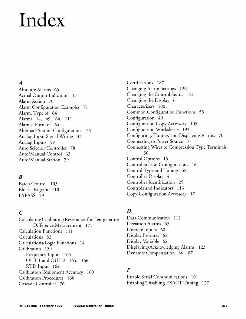
Index
AAbsolute Alarms 65Actual Output Indication 17Alarm Action 70Alarm Configuration Examples 71Alarm, Type of 64Alarms 14, 49, 64, 111Alarms, Form of 64Alternate Station Configurations 76Analog Input Signal Wiring 33Analog Inputs 59Auto Selector Controller 78Auto/Manual Control 63Auto/Manual Station 79
BBatch Control 103Block Diagram 110BYPASS 59
CCalculating Calibrating Resistances for Temperature
Difference Measurement 171Calculation Functions 111Calculations 82Calculations/Logic Functions 14Calibration 159
Frequency Inputs 165OUT 1 and OUT 2 165, 166RTD Input 164
Calibration Equipment Accuracy 160Calibration Procedures 160Cascade Controller 76
Certifications 187Changing Alarm Settings 126Changing the Control Status 121Changing the Display 6Characterizers 100Common Configuration Functions 58Configuration 49Configuration Copy Accessory 105Configuration Worksheets 193Configuring, Tuning, and Displaying Alarms 70Connecting to Power Source 3Connecting Wires to Compression Type Terminals
30Control Options 15Control Station Configurations 16Control Type and Tuning 58Controller Display 4Controller Identification 25Controls and Indicators 113Copy Configuration Accessory 17
DData Communication 112Deviation Alarms 65Discrete Inputs 60Display Features 62Display Variable 62Displaying/Acknowledging Alarms 123Dynamic Compensation 86, 87
EEnable Serial Communications 101Enabling/Disabling EXACT Tuning 127
MI 018-885 February 1998 762CSA Controller – Index 287
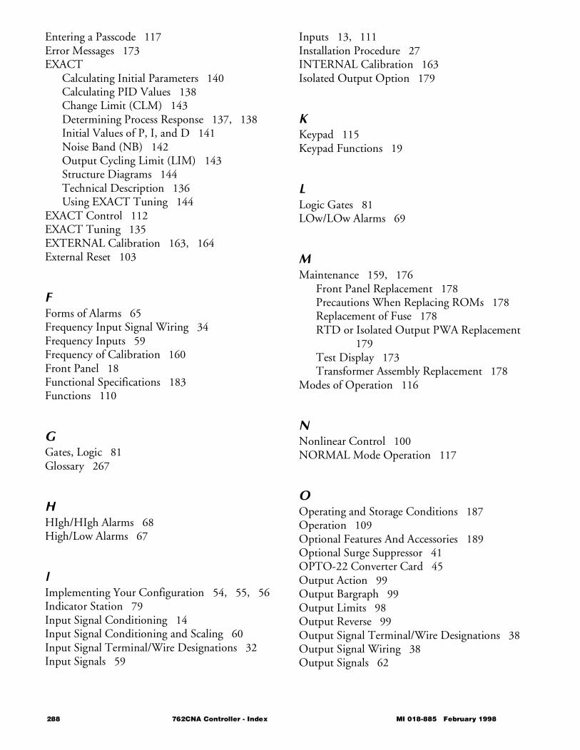
Entering a Passcode 117Error Messages 173EXACT
Calculating Initial Parameters 140Calculating PID Values 138Change Limit (CLM) 143Determining Process Response 137, 138Initial Values of P, I, and D 141Noise Band (NB) 142Output Cycling Limit (LIM) 143Structure Diagrams 144Technical Description 136Using EXACT Tuning 144
EXACT Control 112EXACT Tuning 135EXTERNAL Calibration 163, 164External Reset 103
FForms of Alarms 65Frequency Input Signal Wiring 34Frequency Inputs 59Frequency of Calibration 160Front Panel 18Functional Specifications 183Functions 110
GGates, Logic 81Glossary 267
HHIgh/HIgh Alarms 68High/Low Alarms 67
IImplementing Your Configuration 54, 55, 56Indicator Station 79Input Signal Conditioning 14Input Signal Conditioning and Scaling 60Input Signal Terminal/Wire Designations 32Input Signals 59
Inputs 13, 111Installation Procedure 27INTERNAL Calibration 163Isolated Output Option 179
KKeypad 115Keypad Functions 19
LLogic Gates 81LOw/LOw Alarms 69
MMaintenance 159, 176
Front Panel Replacement 178Precautions When Replacing ROMs 178Replacement of Fuse 178RTD or Isolated Output PWA Replacement
179Test Display 173Transformer Assembly Replacement 178
Modes of Operation 116
NNonlinear Control 100NORMAL Mode Operation 117
OOperating and Storage Conditions 187Operation 109Optional Features And Accessories 189Optional Surge Suppressor 41OPTO-22 Converter Card 45Output Action 99Output Bargraph 99Output Limits 98Output Reverse 99Output Signal Terminal/Wire Designations 38Output Signal Wiring 38Output Signals 62
288 762CNA Controller - Index MI 018-885 February 1998
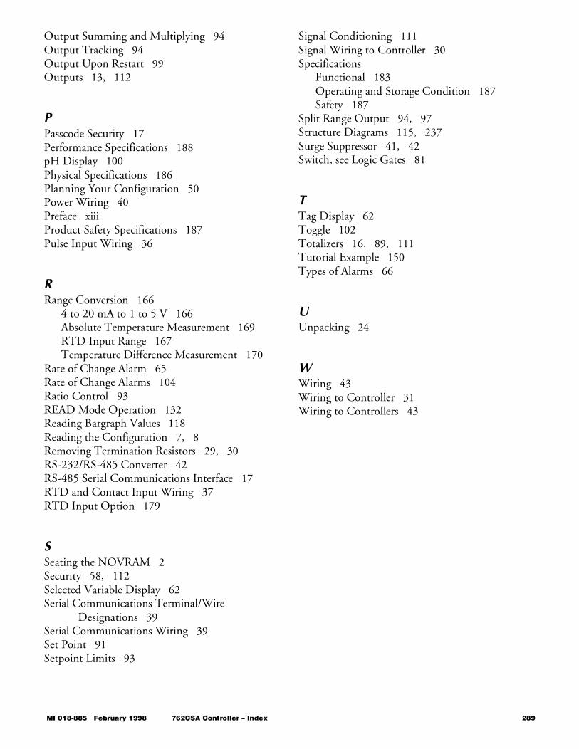
Output Summing and Multiplying 94Output Tracking 94Output Upon Restart 99Outputs 13, 112
PPasscode Security 17Performance Specifications 188pH Display 100Physical Specifications 186Planning Your Configuration 50Power Wiring 40Preface xiiiProduct Safety Specifications 187Pulse Input Wiring 36
RRange Conversion 166
4 to 20 mA to 1 to 5 V 166Absolute Temperature Measurement 169RTD Input Range 167Temperature Difference Measurement 170
Rate of Change Alarm 65Rate of Change Alarms 104Ratio Control 93READ Mode Operation 132Reading Bargraph Values 118Reading the Configuration 7, 8Removing Termination Resistors 29, 30RS-232/RS-485 Converter 42RS-485 Serial Communications Interface 17RTD and Contact Input Wiring 37RTD Input Option 179
SSeating the NOVRAM 2Security 58, 112Selected Variable Display 62Serial Communications Terminal/Wire
Designations 39Serial Communications Wiring 39Set Point 91Setpoint Limits 93
Signal Conditioning 111Signal Wiring to Controller 30Specifications
Functional 183Operating and Storage Condition 187Safety 187
Split Range Output 94, 97Structure Diagrams 115, 237Surge Suppressor 41, 42Switch, see Logic Gates 81
TTag Display 62Toggle 102Totalizers 16, 89, 111Tutorial Example 150Types of Alarms 66
UUnpacking 24
WWiring 43Wiring to Controller 31Wiring to Controllers 43
MI 018-885 February 1998 762CSA Controller – Index 289

ISSUE DATES JAN 1995 MAY 1995 FEB 1996 FEB 1998
Vertical lines to right of text or illustrations indicate areas changed at last issue date.
MB 100 Printed in U.S.A. 0298