controledge hc900 controller controlware specifications · gas compressibility calculations aga8...
TRANSCRIPT

ControlEdge HC900 Controller
Controlware Specifications
51-52-03-42, April 2018
Overview
ControlEdge HC900 Controller Controlware is the execution
environment, control algorithms and firmware infrastructure
programmed into the controller’s memory to allow users to
apply the product in process control applications.
Operation
A control strategy configuration in the ControlEdge HC900
controller consists of function blocks, or predefined
algorithms that get executed in a sequential manner during a
scan cycle. During controller configuration the user specifies
the quantity and type of function blocks needed for the
application.
Two scan engines (Fast and Normal) contain the specific
function blocks and the execution sequence to run its blocks.
Physical inputs are read at the start of each scan cycle, then
all function blocks are executed according to the execution
order, then physical outputs are updated. Due to their
nature, TPS, TPO and PPO functions have their physical
outputs updated during their execution.
The execution environment for the controller is based on two
deterministic execution cycles, one for fast logic type
operations and a second cycle for normal analog based
operations. Within these two fixed time cycle operations,
time is allocated by the system to execute other functions
such as communication tasks, and background diagnostic
checking. These tasks are assigned function block numbers
1 through 100 and may not be altered by the user. The
user’s configuration begins with function block number 101.
In order to maintain the deterministic operation of the
controller, time may be added to the scan cycles in fixed
increments based on the size and scope of the user’s
configuration. The maximum time required to execute the
user’s configuration is determined when a configuration is
loaded into the controller and does not change during on-
line operation.
The time needed to execute communications and other
background tasks is accounted for in the configuration timing
and does not impact the deterministic operation of the
controller.
For more information see specification sheets:
ControlEdge HC900 Controller 51-52-03-31
ControlEdge 900 Platform Modules 51-52-03-41
Designer Software 51-52-03-43
900 Control Station Operator Interfaces 51-52-03-46.
Controller Configuration
User configurations are permanently retained in flash memory
in the controller. In the event a PC configuration file is lost or
misplaced, it can be easily reconstructed using the upload
function of the Designer configuration software or via the 900
Control Station. Simply read the configuration from the
controller to exactly duplicate the original configuration,
including all text descriptions. In the event edits to a
controller’s configuration are required after the unit is in
operation, the on-line download function of the ControlEdge
HC900 Designer software allows configuration changes while
in the Run/Program mode, limiting process disturbances.
During power interruptions to the controller the dynamic
control status is retained in battery backed RAM memory. This
function minimizes process upsets during momentary power
interruptions and other discontinuous operation. If power is
lost and the battery is not available, the controller defaults to
the configuration stored in Flash memory and a cold start is
performed.
Function Block Attributes
The CPUs of the ControlEdge HC900 provide different
function block capacities to allow matching controller
performance to application needs. The C30 CPU provides up
to 400 function blocks, the C50 up to 2000, and the C70/C75
up to 5000 function blocks. Similar proportions apply to
available support items such as soft-wire connections and
page connectors.

Principal function blocks may be identified with tag names
and they have dedicated widgets provided in Honeywell
Station Designer/Control Station. All function blocks support
user-entered tags on their outputs.
Function blocks that define the operation of physical inputs
and outputs provide a failsafe state. The failsafe state will be
the state of the physical output resulting from a fault
condition. See ControlEdge HC900 Function Block Types
(page 5) for available failsafe actions. Function blocks that
depend on physical hardware for their operation have also a
fail output pin on the block that may be used in a control
strategy to trigger appropriate default operations. A fail pin
on a function block activates when the associated I/O
module fails or when communications to a module in a
remote rack fails. Validated Output function blocks provide
two additional fault monitoring pins. FBFAIL, stands for
Feedback Fail, and activates when the corresponding
INPUT channels fails, VFAIL, stands for Verification Fail,
and activates when the associated input does not match the
driven output. Voting INPUT function blocks also provide two
additional fault monitoring pins, SFAIL, stands for Source
Fail, it activates when one or more of the configured INPUT
channels fail, VFAIL activates when one or more of the
channels disagree. All of these validated function blocks
contain a disable pin that may be used to disable the
function block and its associated FAIL logic. The validated
I/O function blocks contain a restart pin that allows the user
to maintain the output and fault outputs until an OFF to ON
transition occurs. This is functionality is useful to maintain a
safe condition while repairs are being made.
Customizable memory allocation
The percentage of memory for recipes (Setpoint Profiles,
Setpoint Schedules, Sequences, Variable recipes) is
adjustable, allowing more space for recipes or for
configuration (i.e., function blocks), whichever is needed. For
details see ControlEdge HC900 Controller specification
51-52-03-31, section “Capacity.”
Advanced control and computational capability
A large assortment of analog and digital function blocks are
available to solve the most demanding control requirements.
Typical analog function blocks include totalizer, free-form
math, average, mass flow, function generator, periodic
timers based on real-time, carbon potential, RH, Dew Point,
signal selection, comparison, and many others.
These blocks may be configured to create control schemes
that precisely address the needs of your process.
Digital status outputs are also provided on many of the
analog function blocks to facilitate intelligent signal alarming
and default operation strategies. Typical logic function
blocks include AND, OR, XOR, NOT, Latch, Flip-flop, On/Off
Delay and Resettable timers, Counters, Free-form Boolean
logic and more. The execution of analog and digital
functions is seamlessly integrated into a single control
strategy in the controller.
Loop Control
The robust control loops of the ControlEdge HC900
Controller support configurations from simple PID to
interactive cascade, ratio, duplex, position proportioning and
three position step for motor positioning or custom control
strategies. Standard for every control loop is auto-tuning
using Honeywell’s performance proven Accutune III tuning
algorithm. A selectable “Fuzzy Logic” algorithm is also
provided for each loop to suppress unwanted process
setpoint overshoot. A soft start feature allows output rate
limiting for protection of a process load on startup or after
power failure.
Setpoint Scheduling
The scheduler function provides up to 8 ramp and soaks
outputs plus up to 8 soak only outputs that operate on a
common time base. The scheduler also supports up to 16
event digital outputs. Soak guarantee, jog to a segment and
nested looping features are also provided. Applications
include multi-zone diffusion furnaces, CVD furnaces, and
environmental chambers.
Logic
Logic programming may be used to implement more robust
and higher speed logic functions in the controller. The fast
scan program executes all inputs, outputs and function
blocks as fast as 10 milliseconds. The fast scan instruction
set includes 2, 4 and 8 input logic blocks with selectable
input inversion plus timers, triggers, latches, counters,
timers, math and other supporting functions. A Sequencer
function is also included with functionality beyond typical
drum sequencers.
Stage
Stage blocks may be configured to control the on and off
states of up to 4 outputs, for the control of processes such
as tank level. Interlocking between stages and between
multiple stage function blocks is available to guarantee
proper output sequencing.

Alternator
Alternator function blocks accept digital inputs and drive
digital outputs in an alternating sequence as determined by
the user. The user may select from 4 alternating styles:
Direct, Rotary, FOFO and Fixed.
AGA (American Gas Association)
The AGA function blocks are divided into two categories:
Gas Compressibility calculations AGA8 Detail (AGA8DL)
and Gross Method (AGA8GS) and Meter Calculations
(AGA3OM- Orifice, AGA7TM – Turbine, and AGA9UM –
Ultrasonic). In almost all configurations, a complete
calculation will consist of a compressibility calculation
followed by a meter calculation.
Calendar Event
The Calendar Event block compares user entered time and
date set points to the real-time clock to generate digital
status (one-shot) outputs that can be integrated into a
control strategy to activate time synchronized activities. The
setpoints of the block’s outputs are grouped into sets to
provide a convenient method to perform periodic changes.
Up to 5 setpoint groups are available for items such as
seasonal time changes. Up to 16 special days can be
designated which override the normal event processing on
that day. For example, selected outputs can be configured to
remain off on holidays.
Sequencers Example Sequence Control
The ControlEdge HC900
controller supports sequencer
function blocks, greatly
enhancing configuration of
sequence operations. Each
sequencer supports up to 16
digital outputs that may be
either on or off in each of 50
states e.g. PURGE, FILL,
HEAT, etc. The sequencer may
have up to 64 sequential steps
that activate the states of the
sequence. Steps of the
sequencer may be configured
to advance based on time, on
event (2 per step), or a manual
advance. A separate jog
function is also provided. The
function can also output an
analog value on a step basis.
The operational sequence for
the steps is retained in a
separate sequence file in the
memory of the controller that
may be selected on-demand
through a user interface or via a
recipe.
Outputs
Step
State State
Name
1 2 3 4 5 6 7 8 9 10 11 12 13 14 15 16
1 1 PURGE 1 0 0 1 0 1 0 0 0 1 1 0 1 0 1 1
2 5 AGITATE 1 0 1 0 1 0 1 0 0 1 1 0 1 0 1 1
3 2 FEED B 0 1 1 1 1 0 1 0 0 1 1 0 1 0 1 1
4 3 MIX 1 1 1 1 1 1 1 1 1 1 1 0 1 0 1 1
5 8 PREHEAT 0 0 0 1 0 0 1 0 0 1 1 0 1 0 1 1
64 50 STOP 0 0 0 0 0 0 0 0 0 0 0 0 0 0 0 1
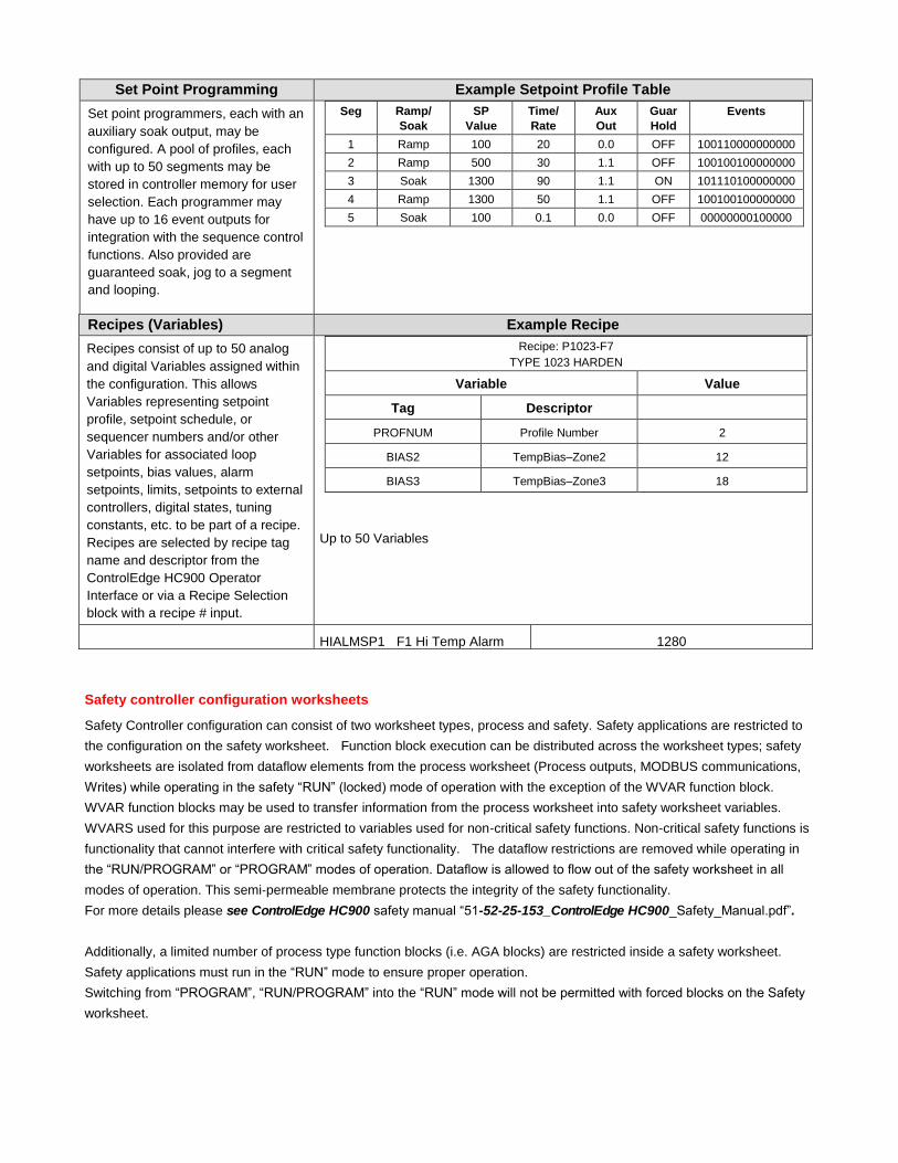
Set Point Programming Example Setpoint Profile Table
Set point programmers, each with an
auxiliary soak output, may be
configured. A pool of profiles, each
with up to 50 segments may be
stored in controller memory for user
selection. Each programmer may
have up to 16 event outputs for
integration with the sequence control
functions. Also provided are
guaranteed soak, jog to a segment
and looping.
Seg Ramp/
Soak
SP
Value
Time/
Rate
Aux
Out
Guar
Hold
Events
1 Ramp 100 20 0.0 OFF 100110000000000
2 Ramp 500 30 1.1 OFF 100100100000000
3 Soak 1300 90 1.1 ON 101110100000000
4 Ramp 1300 50 1.1 OFF 100100100000000
5 Soak 100 0.1 0.0 OFF 00000000100000
Recipes (Variables) Example Recipe
Recipes consist of up to 50 analog
and digital Variables assigned within
the configuration. This allows
Variables representing setpoint
profile, setpoint schedule, or
sequencer numbers and/or other
Variables for associated loop
setpoints, bias values, alarm
setpoints, limits, setpoints to external
controllers, digital states, tuning
constants, etc. to be part of a recipe.
Recipes are selected by recipe tag
name and descriptor from the
ControlEdge HC900 Operator
Interface or via a Recipe Selection
block with a recipe # input.
Recipe: P1023-F7
TYPE 1023 HARDEN
Variable Value
Tag Descriptor
PROFNUM Profile Number 2
BIAS2 TempBias–Zone2 12
BIAS3 TempBias–Zone3 18
Up to 50 Variables
HIALMSP1 F1 Hi Temp Alarm 1280
Safety controller configuration worksheets
Safety Controller configuration can consist of two worksheet types, process and safety. Safety applications are restricted to
the configuration on the safety worksheet. Function block execution can be distributed across the worksheet types; safety
worksheets are isolated from dataflow elements from the process worksheet (Process outputs, MODBUS communications,
Writes) while operating in the safety “RUN” (locked) mode of operation with the exception of the WVAR function block.
WVAR function blocks may be used to transfer information from the process worksheet into safety worksheet variables.
WVARS used for this purpose are restricted to variables used for non-critical safety functions. Non-critical safety functions is
functionality that cannot interfere with critical safety functionality. The dataflow restrictions are removed while operating in
the “RUN/PROGRAM” or “PROGRAM” modes of operation. Dataflow is allowed to flow out of the safety worksheet in all
modes of operation. This semi‐permeable membrane protects the integrity of the safety functionality.
For more details please see ControlEdge HC900 safety manual “51-52-25-153_ControlEdge HC900_Safety_Manual.pdf”.
Additionally, a limited number of process type function blocks (i.e. AGA blocks) are restricted inside a safety worksheet.
Safety applications must run in the “RUN” mode to ensure proper operation.
Switching from “PROGRAM”, “RUN/PROGRAM” into the “RUN” mode will not be permitted with forced blocks on the Safety
worksheet.

ControlEdge HC900 Function Block Types
I/O Blocks (F=Fast Scan Rate, N=Normal Rate)
Analog Input N Universal Analog Input, with table selection of input type. (For input types see
ControlEdge HC900 Controller Module Specification 51-52-03-41)
Filter – 1st order lag, 0 to 120 seconds
Bias – Input value adjust for calibration correction
Burnout – Off, Upscale, Downscale, Default Value
Warn Output – activates if thermocouple resistance > 100 ohms.
Input Disable –digital input when ON disables input, sets output to a defined
default
Bad Channel Detection – Optional selection to treat a sensor failure and
hardware fault the same.
Analog Input with Voting N Universal Analog Input, with table selection of input type. (For input types see
ControlEdge HC900 Controller Module Specification 51-52-03-41). AI-V differs
from AI in that multiple inputs (up to 3) may be specified, the values of the inputs
(whose channel has not failed) must match within 3% for the input value to be
considered good overall.
The block output pin reflects the first channel that is within the 3% tolerance.
This block contains three output status pins:
Fail PIN – reflects the highest failure level where the value of the block cannot
be determined. The Blocks Output will reflect the programmed failsafe value.
SFAIL – Stands for Source failure. This pin turns ON if a channel/module has
failed
VFAIL – Stands for Validation Failure. This pin turns ON if the SFAIL Pin is
OFF and one of the selected channels is outside the 3% tolerance band.
Monitoring the block directs the operator to the failure source.
Filter – 1st order lag, 0 to 120 seconds
Bias – Input value adjust for calibration correction
Bad Channel Detection – Optional selection to treat a sensor failure and a hardware fault as the same.
Disable Pin – Places the block output to the selected Failsafe value and turns the Output status pins OFF.
For safety configurations it is recommended that the channel inputs physical
source be from different input modules. This provides a means to correct the
failure achieving higher reliability. Additionally locating the modules on
independent racks increases availability to the highest level.
Analog Input RCJ N This block is used only for Thermocouples when the thermocouple Cold
Junction is in a remote location, i.e., NOT connected at the AI module. Cold
Junction compensation is performed using the value presented at the RCJ input,
which is a temperature value in degrees C of the remote junction and which will
come from another AI block. CJ compensation and linearization is performed in
the block producing a value in engineering units at the OUT pin. Fail status of
the AI block measuring the Remote CJ can be applied to the RSTAT pin. (i.e. if
the RCJ measurement Fails, the Thermocouple measurement fails)
Analog Output N Regulated analog output current
Input scaling in Engineering Units, Output scaling within 0 and 20 mA
Slew rate (rate of change in mA/sec.) definable, Fail output pin is ON when
output fail sensed.
Failsafe definable as High, Low, Hold or go to a user specified value

I/O Blocks (F=Fast Scan Rate, N=Normal Rate)
Analog output with Validation N Regulated analog output current with assignable feedback channel for output
validation.
Input scaling in Engineering Units, Output scaling within 0 and 20 mA Slew rate
(rate of change in mA/sec.) definable. The feedback channel range is fixed to
the output range with selection of the appropriate shunt (62.5, 100, 250, 500
ohms).
Failsafe definable as High, Low, Hold or go to a user specified value on the
Process worksheet. Failsafe value on the Safety worksheet is set to OFF.
This block contains three output status pins:
FAIL PIN – reflects the highest failure level where the value of the output may
be in error or the output modules loses communication to the controller. The
Blocks Output will reflect the programmed failsafe value and the physical
channel’s output will be driven to its configured Failsafe value.
FBFAIL PIN – Stands for Feedback failure. This pin turns ON if an assigned
input channel fails.
VFAIL PIN – Stands for Validation Failure. This pin turns ON if the FBFAIL Pin
is OFF and the assigned input channel is outside the 3% tolerance band.
Input Pins
Restart PIN – This Pin, if connected, releases the output from failsafe mode. A
transition from Low to High with error free inputs is required for the operation to
work. This provides a means to correct the failure and resume operation in a
safe controlled fashion.
Disable Pin – Places the block output to the selected Failsafe value and turns
the Output status pins OFF.
Digital Input (1) F, N Provides the digital status of a digital input point. The output status may be
inverted.
Failsafe definable as ON, OFF or Hold last state
Digital Input with Voting F,N Digital Input, with voting DI-V differs from AI-V in that multiple inputs (up to 3)
may be specified. Voting is achieved using a binary, On – OFF state.
The block output pin reflects vote of the majority of valid, no failures, input
channels. This block contains three output status pins:
Fail PIN – reflects the highest failure level where the value of the block cannot
be determined. The blocks output will reflect the programmed failsafe value.
SFAIL – Stands for Source failure. This pin turns ON if an assigned channel
has failed.
VFAIL – Stands for Validation Failure. This pin turns ON if the SFAIL Pin is
OFF and one of the assigned channels is in the minority.
Monitoring the block directs the operator to the failure source.
For safety configurations it is recommended that the channel inputs physical
source be from different input modules. This provides a means to correct the
failure achieving higher reliability. Additionally locating the modules on
independent racks increases availability to the highest level.
Digital Input (Up to 8 inputs) F, N Provides the digital status of the first or last 8 digital inputs of a 16 point input
card. The output status may be inverted.
Failsafe definable per input as ON, OFF or Hold last state
Digital Output (1) F, N Directs a digital status to a physical logic output. Output status may be inverted.
Failsafe definable as ON, OFF or Hold last state

I/O Blocks (F=Fast Scan Rate, N=Normal Rate)
Digital output with Validation N Digital output current with assignable feedback channel for output validation.
Two physical channels are configured in this block. One output channel and a
matching input type channel.
Failsafe definable as High, Low, or Hold on the Process worksheet.
Failsafe value on the Safety worksheet is set to Low.
This block contains three output status pins:
FAIL PIN – reflects the highest failure level where the state of the output may be
in error or the output modules loses communication to the controller. The
Blocks Output will reflect the programmed failsafe state and the physical
channels output will be driven to the configured Failsafe state.
FBFAIL PIN – Stands for Feedback failure. This pin turns ON if an assigned
input channel fails.
VFAIL PIN – Stands for Validation Failure. This pin turns ON if the FBFAIL Pin
is OFF and the remaining inputs do not agree.
Input Pins - Restart
PIN – This Pin, if connected, releases the output from failsafe mode. A
transition from Low to High with error free inputs is required for the operation to
work. This will provide a means to correct the failure and resume operation in
a controlled fashion.
Disable Pin – Places the block output to the selected Failsafe value and turns
the Output status pins OFF.
Digital Output (Up to 8 outputs) F, N Directs 8 digital statuses to 8 physical logic outputs of an 8 point output card or
to the first or last 8 physical logic outputs of a 16 point output card. Output status
may be inverted. Both fast logic (27 ms) and normal logic (500ms analog rate)
blocks available.
Failsafe definable per input as ON, OFF or Hold last states.
Time Proportioning Output
(applied to any PID output)
N Proportions the amount ON time and OFF time of a digital output.
Input scaling in engineering units
Cycle time—2 second to 120 seconds
Output minimum ON and OFF time—0 seconds to 15 seconds
Failsafe definable per input as ON, OFF or Hold last duty cycle

I/O Blocks (F=Fast Scan Rate, N=Normal Rate)
Position Proportional Output N A combination Input and Output function block that accepts position feedback
input and generates forward/reverse digital outputs.
Positions actuators with slidewire, current or voltage position feedback sensors.
Provides output pins for actuator position (0 to 100%), motor fail, and feedback
fail – automatically defaults to 3-position step on feedback fail.
Input scaling in engineering units
Actuator speeds from 12 to 300 seconds
Output limits – adjustable (between 0 and 100%)
Deadband – adjustable (0.5 to 5%)
Feedback filter – adjustable (0 to 3 sec.)
Feedback input types:
Slidewire 100 to 250 ohms ( requires AI card 900A01-0002)
Slidewire 250 to 1000 ohms (requires AI card 900A01-0002)
mA - 4 to 20mA
mA - 0 to 20mA
Voltage - 0 to 1V
Voltage - 0 to 5V
Feedback calibration – HC Designer, 1042 or 559 Operator Interfaces
Automatic, Semi-automatic, and Hand methods supported.
Failsafe – Hold last position.
Pulse Input F, N Reads a single input channel from a Pulse/Frequency/Quadrature input module.
It scales pulses from this input to user-configured engineering units. The scaling
typically represents a quantity or rate.
Pulse Output F, N Outputs a pulse train of user controllable duration. It controls a relay on a
Pulse/Frequency/Quadrature module.
Frequency Input F, N Used for measuring speed and flow rate. It reads a single frequency channel
from a Pulse/Frequency/Quadrature input module. The signal is ignored
(filtered) if it does not meet the selected pulse width/frequency range conditions.
Otherwise, the signal is scaled from the selected frequency span to the selected
output range in engineering units.
Quadrature Input F, N Measures/controls movement of an actuated device. A digital encoder
connected to the actuated device produces two channels (A and B) of square
waves, offset 90 degrees. The block measures by counting the waves’ rising
edges.
Universal IO Analog Input F,N Reads value of an UIO-Analog Input from a specified real I/O address
Please refer “51-52-25-109” manual for more details.
Universal IO Analog Output F,N Regulated analog output current
Please refer “51-52-25-109” manual for more details.
Universal IO Digital Input F, N Provides the digital status of a digital input point. The output status may be
inverted.
Please refer “51-52-25-109” manual for more details.
Universal IO Digital Output F, N Directs a digital status to a physical logic output. Output status may be inverted.
Please refer “51-52-25-109” manual for more details.

Control Loop Function Blocks (F=Fast Scan Rate, N=Normal Rate)
PID
N
PID algorithm includes:
Accutune III auto-tuning and selectable fuzzy logic overshoot suppression
PID A (normal) or PID B (only integral response to SP change) operation,
DUPA and DUPB operation which switches tuning constants for heat/cool
applications
Two sets of PID constants selectable via program control. Choice of Gain
or Proportional Band entry and Integral time or Repeats/minute entry
Setpoints—Two setpoint values or one value and one remote setpoint
Setpoint tracking – Local SP tracks PV or RSP on a RSP to LSP change
Setpoint limits, output limits, SP rate of change
Soft start for output rate limiting on startup or after power fail (not available
with output tracking)
Ratio and Local/Remote Bias selections for Ratio control applications
Feedforward input (scaled in % of output)
Back calculation output for Cascade operation (supplied to primary loop)
Output tracking to track a remote input (for backup applications)
Remote A/M, R/L mode switching and mode status outputs
Function block access to tuning constants for gain scheduling
Alarms—Two outputs with up to two high, low, or dev band conditions each
Inputs: PV, remote setpoint, feedforward, output track and track command,
ratio, bias, switch block connection, mode switch block connection, and back
calculations
Outputs: Control output, working setpoint, alarm status (2), Autotune indication,
mode status
PID for Carbon Potential
(displaces PID)
N
A combined carbon potential calculation and PID algorithm for controlling the
carbon potential of furnace atmospheres using a Zirconia probe input and
temperature input. Local/remote %CO adjustment, probe manufacturer
selection (4 selections), anti-sooting protection, Dewpoint calculation output,
and furnace factor adjustment is supported; probe burn-off configurable.
Consumes 1 loop.
PID with 3 Position Step Output N Motor position control without position sensing. Standard PID features with
addition of hysteresis (in %) and full stroke time (in sec.) entries for motor.
Forward and Reverse outputs specified within the block. Physical outputs
updated during block execution.
ON/OFF Control (displaces PID) N ON/OFF control algorithm with selectable hysteresis. Consumes 1 loop.
Loop Switch Inputs N Digital interface to control loops to initiate autotuning, change control action,
force bumpless transfer, select tuning set #1 and select tuning set #2. Connects
to PID (all) and ON/OFF block switch input.
Loop Mode Switch N Digital interface to control loops to select automatic or manual modes and/or
local or remote setpoint. Connects to all control loop types.
Mode Decoder (Mode Flags) N Decodes control loop mode status into a set of discrete (Boolean or digital)
mode flags. Outputs activate for states: Auto, Manual, Initialization Manual,
Local Override, Local Setpoint, Remote Setpoint
Write Tuning Constants N Automatically changes the GAIN, RATE, and RESET parameters of an internal
PID loop without operator interaction. A digital input controls changes.
Auto-Manual Bias
(for Boiler Control applications)
(displaces PID)
N Allows a manually adjusted output to be maintained on transfer to automatic by
applying bias to the input signal (from a Steam master to adjust participation of
boiler). Bias value is maintained as output value tracks input value changes.
Consumes 1 loop.

Setpoint Programmer and Recipe Function Blocks (F=Fast Scan Rate, N=Normal Rate)
Setpoint Programmer N Produces a setpoint output for a time-based ramp/soak profile that is loaded into
the block.
Inputs:
Process Variables, up to 3, to establish setpoint guarantee operation based on a
deviation band from setpoint. Profile Number (for auto-load of a profile # for next
run), New Starting Segment (uses a Set input to enter a new segment number).
Digital Inputs:
Enable (allows programmer to be operated), Set (to load a program or new start
segment), Start, Hold, Restart (from power failure, can allow slower ramp up to
previous SP to protect product), Reset, Advance, Jog (to a specified segment),
and Guarantee Hold (to synchronize with another programmer).
Outputs:
Setpoint value, segment number, program number, time remaining in segment,
time elapsed in segment, program elapsed time.
Digital Outputs:
Status (Ready, Running, Hold, Stopped), synchronize hold state, program state
Setpoint Program Events (up to
16 events per block)
N Provides up to 16 digital status outputs that may be ON or OFF on a per segment
basis. Inputs include program number, segment number, and program state
(READY, RUN, HOLD, GHOLD, or STOP) from setpoint program block from
program state output.
Setpoint Program Synchronizer N Used to synchronize the operation of two setpoint programs given the Run, Hold
and Reset signals from each program.
Recipe Block F,N Used to initiate loading of recipe values into a chosen set of controller variables
based on a recipe number. Inputs include recipe number and load command,
allowing remote recipe selection.
Setpoint Scheduler Function Blocks (F=Fast Scan Rate, N=Normal Rate)
Setpoint Scheduler
N Produces up to 8 ramp or soak setpoint outputs on a common single time base.
(See Scheduler description for details.)
Inputs:
Process variables, up to 8, to establish setpoint guarantee operation based on
deviation from setpoint. Schedule number is used for automatic schedule loading
and starting segment number allows first segment selection.
Digital inputs:
Dedicated input for connection to State Switch block output.
Outputs:
Up to 8 setpoint values, segment number, schedule number, time remaining in
segment, time elapsed in segment, schedule elapsed time.
Digital Outputs:
Dedicated output for connection to State Flags block input.
State Switch Block N Provides digital switch status inputs to the Scheduler block for Run, Hold, Reset,
Ghold, Advance and Jog.
State Flags Block N Accepts status output from the Scheduler block and provides digital output signals
for Run, Hold, Ghold, Ready and Stop.
Setpoint Scheduler Auxiliary
Output Block
N Provides up to 8 additional analog setpoint (soak only) values for each segment of
the schedule.
Inputs: Up to 8 process variables used for display.
Event Decoder N Provides up to 16 digital outputs that may be ON or OFF on a per segment basis.

Auxiliary Control Function Blocks (F=Fast Scan Rate, N=Normal Rate)
Lead Lag Signal Conditioner N Modifies an analog input value to include lead and lag time constants when a digital input is true. Lead time constant = 0 minutes to 99 minutes Lag time constant = 0 minutes to 99 minutes
Function Generator N Generates an output characteristic curve based on up to 11 configurable
“breakpoints” for input and output values.
High/Low Limiter F, N Limits an analog variable between high and low limit values. Provides separate
digital status outputs when high or low limit values are exceeded.
Rate (Velocity) Limiter F, N Limits the rate at which an analog variable can change when a logic input is ON.
Provides independent increasing and decreasing rate of change limit values.
Separate digital status outputs indicate when high or low rate limits are active.
Rate of Change F, N Provides an output value representing the rate of change value of the input in
units per minute. Output value is positive for increasing input values and
negative for decreasing input values. Two setpoint values and digital outputs
are provided to indicate excess increasing or decreasing rates of change or
insufficient increasing or decreasing rates of change.
Read Constant F, N Provides a read access to internal static parameters of selected blocks by Block
number and parameter index number.
Write Constant F, N Provides write access to internal static parameters of selected blocks by Block
number and parameter index number.
Write Variable F, N Provides a write of a value to a selected analog or digital variable number based
on the ON state of a digital input. Writes into the safety worksheet (Safety
controllers) are only configurable when the variable is enabled for non-critical
safety functions. When operating in Run-Locked/Safe Mode.
Track and Hold N Allows updating or holding the value of an analog input based on the state of a
digital input.
BCD Translator F, N Accepts up to 8 digital inputs in sequence and interprets the ON/OFF status of
the first 4 inputs as a BCD value between 0 and 9, and the second 4 digits as a
value between 10 and 90.
Digital Encoder N A 16 input block whose output is the decimal value of the number of ON inputs.
Digital Decoder N A block whose 16 outputs are the binary equivalent of the input’s decimal value.

Specific Application Principal Blocks (F=Fast Scan Rate, N=Normal Rate)
Device Control
(for Pump Control)
N Provides device control (pumps, etc) including Start, Stop, Feedback Delay
times along with feedback confirmation and failure check.
Stage N Accepts one or two analog variables and compares the values to high and low
setpoints for each of 4 stages per block. Outputs are digital signals that remain
ON after exceeding one setpoint until exceeding the second setpoint value for
the specific stage.
Ramp N Accepts an analog variable and re-scales the value to new, user specified units.
Up to 4 re-scale calculations may be configured per block. The re-scale
calculation that is currently active is controlled by digital inputs to the block.
Digital inputs may also be used to force the output to a high or low limit value.
Alternator N The alternator accepts up to 16 digital inputs and, on a one for one basis, turns
on up to 16 digital outputs as determined by a user specified alternating
sequence. Alternator sequences include:
Direct – Inputs are mapped to specific outputs.
Rotary – Outputs are managed on a Last ON/ First Off (LOFO) basis and the
mapped sequence indexes by one each time all of the outputs are off.
FOFO – First On, First Off alternates the outputs based on the sequence in
which the outputs were turned on. The first output to turn on is moved to the end
of the list once it turns off.
Fixed – The output sequence follows a user specified mapping sequence. A
manual advance causes the mapping sequence to index by one when enabled.
Both “make-before –break” and “break –before –make” selections are available
for the block with user specified time delays for output changes.
Signal Selector Function Blocks (F=Fast Scan Rate, N=Normal Rate)
High Selector/Low Selector F, N Provides the highest (high select) or lowest (low select) of two analog input
variables.
Switch F, N Output switches between two analog input values based on the status of a
digital input.
Bumpless Analog Transfer N Output switches between two analog input values based on the status of a
digital input. When switched, output ramps to the new value at a specified rate.
A rate value is available for each direction.
Rotary Switch F, N Single output is selected from up to 8 analog values based on the numerical
value of a select input (1 to 8).

Calculation Function Blocks (F=Fast Scan Rate, N=Normal Rate)
Compare F, N Compares one analog variable to a second analog variable and generates
separate digital outputs to indicate greater than, equal, or less than status.
Absolute Value F, N Provides an absolute value output for a single analog variable input.
Square Root F, N Output is the square root of a single analog variable input.
Mass Flow N Calculates the mass flow of gases when measuring flow using an orifice plate.
Output = Kg * sqrt((Kx * X + Bx) (Ky * Y + By)/(Kz * Z + Bz))
With inputs X = differential pressure Y = pressure, and Z = temperature.
A low flow cut-off feature provides a user-specified drop-off value below which
the output goes to zero.
Minimum – Maximum – Average
– Sum
N Accepts inputs from up to 6 analog variables and outputs analog variables
representing the highest value, lowest value, average value, sum, and standard
deviation. Removes bad inputs and provides an alarm output for deviations of
any variable outside user-specified standard deviation.
Negate F, N Accepts a single analog variable input and negates the output.
Totalize F, N Integrates an analog variable using a specified rate. Rate may be in units per
minute, hour, or day. A preset is provided to indicate when a specific quantity
has been accumulated. Separate enable and reset inputs are provided.
Deviation Compare N Compares up to 6 analog variables to deviation limits set around a 7th variable.
If any variable is outside the limits, a digital signal is provided.
Dewpoint N A Dewpoint PV derived from high temperature O2 sensor is supplied to a PID
function block for furnace Dewpoint control. Used in conjunction with other
blocks including a PID to generate more elaborate control strategies than that
provided by the carbon potential function block.
Continuous Average F, N Provides the average value of a single analog parameter for a user-specified
time period, plus the running average within the time period. Average value is
updated at the end of each sample period. Time periods to 1440.0 minutes are
supported. A hold input allows excluding samples from the average when
active.
Orifice Meter (AGA3) N Calculations for Orifice Metering – When connected to an AGA8 block, the input
value and multiple related parameters will be obtained from the AGA8 block.
The meter block will use this information to inherit the AGA8 block data for use
in the calculations.
Turbine Meter (AGA7) N Calculations for gas measurement by Turbine Meters – When connected to an
AGA8 block, the input value and multiple related parameters will be obtained
from the AGA8 block. The meter block will use this information to inherit the
AGA8 block data for use in the calculations.
Ultrasonic Meter (AGA8) N Calculations for gas flow measurements from multi-path Ultrasonic Meters –
When connected to an AGA8 block, the input value and multiple related
parameters will be obtained from the AGA8 block. The meter block will use this
information to inherit the AGA8 block data for use in the calculations.

Detail (AGA8) N The Detail method (AGA8DL) uses the gas analysis of up to 21 components.
From the gas analysis, the super-compressibility factor, gas density at flowing
and standard conditions, and gas relative density at standard conditions are
calculated for input into the AGA calculation for the meter type chosen.
Used when accurate gas analysis is available either via an on-line gas analyzer
or from laboratory measurements. The Detail method can handle up to 21 gas
components typically found in natural gas. If this information is available, the
Detail method is preferable, as accurate results are obtainable over a wider
range of conditions than the Gross method.
Gross (AGA8) N The Gross method (AGA8GS) is used to approximate natural gas by treating it
as a mixture of three components, equivalent hydrocarbon component, Nitrogen
and Carbon Dioxide. It is typically used for dry, sweet (no H2S) natural gas.
There are two methods used:
Gross Method 1 calculates the super-compressibility and gas density from
knowledge of the relative density, heating value and carbon dioxide, hydrogen
and carbon monoxide components.
Gross Method 2 calculates the super-compressibility and gas density from
knowledge of the relative density, Nitrogen, carbon dioxide, hydrogen and
carbon monoxide components.
The Gross Method only works over a limited range of conditions but requires
less instrumentation to implement.
HVAC Function Blocks (F=Fast Scan Rate, N=Normal Rate)
Relative Humidity N Calculates the relative humidity using wet bulb, dry bulb, and atmospheric
pressure inputs. Output may be in degrees Fahrenheit or Celsius.
Humidity and Enthalpy N Calculates the Absolute Humidity and Enthalpy based on the inputs for air
temperature, air relative humidity and barometric pressure.
Psychrometric N Accepts Temperature, relative Humidity and Barometric Pressure inputs and
calculates humidity ratio, enthalpy, dewpoint, wet bulb temperature and
absolute moisture. Calculations may be in Metric or English.
Math Function Blocks (F=Fast Scan Rate, N=Normal Rate)
Scale and Bias F, N Output = (K * X) + b with single analog variable input X.
Two and Four Input Math F, N Executes +, – or * on two or four analog variable inputs, / on two inputs.
Free Form Math N Calculates the result of a user-specified equation with double precision. The
block accepts up to 8 input signals (including Constants or Variables).
Operators include: +, -, , /, ^, and multiple levels of parentheses. Functions
include: absolute value, exp, ln, Log, neg, sqrt. Example: a*(sqrt(b+c))+d

Logic Function Blocks (F=Fast Logic Rate, N=Normal Rate)
AND, OR, XOR (2 inputs)
Boolean logic blocks
F, N Provides a digital status output based on the digital status of two digital inputs
for logic AND, OR, or XOR (exclusive OR) operations. Input status of each input
may be inverted.
AND, OR (4 and 8 inputs)
Boolean logic blocks
F, N Provides a digital status output based on the digital status of four or eight digital
inputs for logic AND or OR operations. Input status of each input may be
inverted.
NOT (Complement) F, N Inverts a logic input status.
Latch F, N Provides a digital output that turns ON when a digital input turns ON and
remains ON (latched) after the input goes OFF until an unlatch input turns ON.
Edge Detection Element
(One-shot) [Trigger]
F, N Provides an ON state of its output for one controller scan when a digital input
goes from OFF to ON.
Selectable Trigger F, N Provides selectable input conditions for triggering its digital output.
Toggle (Flip-Flop) F, N Provides an ON state output when a digital input goes from OFF to ON and the
previous state of the output was OFF, and an OFF state output when the digital
input goes from OFF to ON and the previous state of the output was ON. A
reset input holds the output OFF when the digital input is ON or active high.
Free Form Logic F, N Reads eight digital inputs and calculates the output based on specified Boolean
logic functions (e.g., AND, OR, NOT, etc.) and multiple levels of parentheses.
Example: (A*B)+C
Pushbutton F, N Provides a one-shot output based on an OFF to ON change of an operator
interface key action. Supports four pushbuttons per block.
Four Selector Switch N Provides up to 16 digital outputs in groups of four outputs each. Only one output
from each group may be ON at a time and when selected automatically turns
other outputs OFF. Simulates 4-position panel selector switches.
Sequencer F, N The sequencer function block controls the output statuses of up to 16 digital
outputs and one auxiliary analog output. Each combination of outputs
represents a “State” of the sequence such as Heat, Mix, or Cool, for example.
The function block supports up to 50 states.
The sequencer contains up to 64 steps. Each step enables a State, allowing for
a State to be designated for several steps.
Each State supports two digital events as inputs that can designate the end of
the associated step.
Time in seconds or minutes, a manual advance, or a digital event can be used
to terminate a sequencer step and cause the sequence to advance.
A pool of sequences, up to 64 steps each, may be stored in controller memory
for quick recall and assignment to any of the sequencers.
Hand/Off/Auto N Provides Hand-Off-Automatic outputs based on digital inputs emulating a
standard H-O-A panel switch

Counters/Timers Function Blocks (F=Fast Logic Rate, N=Normal Rate)
Resettable Timer F, N Provides a timing function based on an enable input. Elapsed time value is
provided as an output. A Preset value allows settings from 1 second to 999999
seconds. A digital output is ON when time value is equal to the preset. An
up/down digital input is provided to allow reverse timing from the preset value. A
pre-load value allows initiating the timer to a non-zero starting time.
Periodic Timer F, N Provides an ON state output for one controller scan cycle based on a specified
time period using the controller real-time clock. Periods may be monthly,
weekly, daily, or time period in a day.
Up/Down Counter F, N Counts the number of raising edge logic transitions on the input to the block up
to a preset value. When the preset value is reached a logic output is enabled. A
reset input resets the block. Value may be set to increase to the preset value or
decrease from the preset value (1–99999).
ON-Delay Timer F, N An OFF to ON change of the digital input is delayed on the block output by a
user-specified time (0.1 seconds to 999.9 seconds).
OFF-Delay Timer F, N An ON to OFF change of the digital input is delayed on the block output by a
user-specified time (0.1 seconds to 999.9 seconds).
ON/OFF Delay Timer F, N Programmable as either ON-Delay Timer or OFF-Delay Timer (above).
Calendar Event N The Calendar Event Block compares user-entered time-and-date setpoints to
the real-time clock to generate digital Event outputs. These Event outputs can
be integrated into a control strategy to activate time-synchronized activities.
Each Calendar Event block supports up to eight Event outputs.
In addition, the block allows you to configure up to five sets of time-and-date
setpoints, called Setpoint Groups. These Setpoint Groups can be used to
activate different sets of time-and-date setpoints to handle different conditions.
Each Calendar Event block supports five Setpoint Groups.
The block also allows you to configure up to 16 Special Days. On these Special
Days the Calendar Event Block will override its normal Event processing for a
24-hour period.
Real Time Clock N The Real Time Clock block provides outputs pins that you can access in your
configuration to make decisions based on the value of the controller’s Real Time
Clock value.
The RTC function block has the following dynamic outputs based on the value
of the real time clock of the controller: Seconds, Minutes, Hours, Day of Week,
Day of Month, Day of Year, Month, and Year.
Time and Date N Controls change between Daylight Saving and Standard time. Indicates when
controller time is in Daylight Saving. If the controller is using a network time
server, indicates if the connection to server has failed.

Alarm and Signal Monitoring Blocks (F=Fast Scan Rate, N=Normal Rate)
High Monitor F, N Accepts two analog values and provides a digital status output if the first input is
higher than the second input. A hysteresis adjustment is provided to prevent
output cycling.
Low Monitor F, N Accepts two analog values and provides a digital status output if the first input is
lower than the second input. A hysteresis adjustment is provided to prevent
output cycling.
Analog Alarm N The analog alarm block accepts an analog signal as a process variable and
compares it to a user-entered limit value (setpoint) to determine an alarm
condition. The setpoint may be entered by the user or be another analog signal
in the controller. Alarm actions may be high, low or high deviation, low deviation
or band deviation. For deviation alarming, a second analog signal provides the
reference and setpoints represent deviation from the reference. The alarm out-
put may be inverted to create normally active digital output. A user selection for
latching until acknowledged or automatically reset is provided. A user-specified
hysteresis value in the engineering units of the process variable is provided. An
on-delay time value up to 240 seconds is available to prevent momentary alarm
actions. A digital reset input is available to disable alarm actions.
System Monitor Block
(1 block for normal scan and 1
block for fast logic scan) – (does
not count against the maximum
block count)
F, N Provides system and start-up status outputs including:
Program scan cycle time
Newstart pulse (ON for one scan cycle after a “cold” start (reset))
Restart pulse (to activate a custom control action on power-up after power loss)
Two common alarm outputs – Active Unacknowledged (ON when at least
one alarm not acknowledged), Active alarm (ON when at least one alarm is
active), for assignment to digital outputs
Time off (the time that power has been off previous to restart)
Low Battery (alert to change battery without power shutdown)
Hardware OK (ON when all hardware including remote racks are OK)
Hi Temp (Cold Junction temperature exceeds limits on a rack)
Bad Block
Master Fail
Locked (controller toggle switch is in Run/Locked or Program position)
DS Limit (OI data storage has reached its alarm limit)
Reserve status of C70R CPU is active
IO Rack Monitor– (does not count
against the maximum block
count)
N One monitor block per rack, 12 racks maximum. Provides I/O module fault
status
Alarm Group (Up to 20 blocks) –
(do not count against the
maximum block count)
N Supports acknowledgement of a group of up to 12 alarms using a controller
digital signal to block, internal or external (for remote acknowledge). Each alarm
group consists of up to 12 alarms. Outputs include Unacknowledged alarm and
Active alarm states. The 30 blocks support up to 360 alarms.
Force Present N Output indicates the presence of any forced blocks in the controller. Input can
clear all forces and prevent new forces.
Redundancy Status N Used with redundant CPUs only, such as C75. The output pins indicate the
lead/reserve status of CPU A and CPU B. The input can force a failover
between CPUs.

Alarm and Signal Monitoring Blocks (F=Fast Scan Rate, N=Normal Rate) continued ..
Four Alarm with Hysteresis F, N Monitors four analog input values and performs up to four high or low alarm
comparisons against the PV input. Hysteresis settings for each alarm are used
to prevent output cycling.
Fault Monitor F, N Provides Control Application a means to take action on numerous fault
conditions. The reaction on detected faults is configurative depending on the
applications for which the ControlEdge HC900 is used. The FMON block has a
fault clear input pin used for clearing all the faults generated and a fault output
pin to display the selected diagnostic fail status. Each FMON function block
requires a rack number, module number and a corresponding diagnostic to be
selected during configuration, depending on the type of diagnostic group
selected
Configuration Access Status N Provides read access to configuration access status values including the
configuration file CRC (Cyclic Redundancy Check). The function block provides
pins to generate the number of times the configuration is downloaded to the
controller, number of times unauthorized TCP write is requested, number of
times the controller password is changed.
IO Module Monitor F,N Provides Control Application a means to take action on numerous fault
conditions. The reaction on detected faults is configurative depending on the
applications for which the ControlEdge HC900 is used. The IMM block has a
fault clear input pin used for clearing IO module faults generated and a fault
output pin to display the selected diagnostic fail status. Each IMM function block
requires a rack number, module number to display faults as outputs at module
level.
Communications Blocks (Peer to Peer) (F=Fast Scan Rate, N=Normal Rate)
PDE (Peer Data Exchange)
Control
N Interfaces to one ControlEdge HC900 peer device, accessed by controller
name, supporting 8 parameter read requests and 4 event-triggered writes.
Outputs may be given tag names for use in configuration strategy. Update rate
can be configured from 500 ms to 5 sec.
PDE Read N Expands Read access for designated ControlEdge HC900 peer to an additional
16 parameters.
PDE Write N Expands Writes to designated ControlEdge HC900 peer by an additional 8
parameters, each triggered on event.
Safety Peer Monitor N Interfaced to one ControlEdge HC900 peer device, accessed by controller
name, supporting peer connection and communication status. Failsafe timeout
and Failsafe action can be configured (This is supported for SIL variants from
versions 6.300 and above).
Safety Analog Import (Read) N Analog signal import (read) access for designated ControlEdge HC900 peer
(This is supported for SIL variants from versions 6.300 and above).
Safety Digital Import (Read) N Digital signal import (read) access for designated ControlEdge HC900 peer
(This is supported for SIL variants from versions 6.300 and above).

Modbus Slave NA Interface to one Modbus slave device, accessed by unit address (1 to 247),
supporting 4 parameter read requests and 4 event triggered writes. Outputs may
be given tag names for use in configuration strategy. Update rate is determined
by the system, with the fastest rate being 1000ms per cycle. Max. 32 Modbus
slave blocks per controller. A maximum of 1024 Modbus parameters for all
slaves are supported per controller.
When the serial port is used with the Modbus Master Advanced protocol (for
gateway applications), the fastest update rate is equal to the Normal Scan rate
of the controller (typically 100 ms per cycle). The master’s actual scan rate is
determined dynamically by the controller based on the following criteria.
-Number of slaves present on the serial link
-Serial port baud rate
-Maximum number of Modbus registers per transaction defined by the user
-Number of Modbus registers used in the configuration
-Number of transactions required per scan cycle
-User configured slave reply timeout
Modbus Read NA Expands Reads from Modbus Slave devices for Modbus Slave blocks to an
additional 16 parameters. Max. 32 Modbus devices.
Modbus Write NA Expands Writes of Modbus Slave blocks to Modbus Slave devices by an
additional 8 parameters, each triggered on event. Max. 32 Modbus devices.
Modbus/TCP Slave NA A communication function block allows the controller to act as a master device
and communicate with slave devices via the Ethernet port of the controller.
Requires one block per slave device, up to 32 devices maximum. Only one
block may be assigned to each slave device. It supports 4 read and 4 write
parameters plus provides digital indication of communication integrity.
Modbus/TCP Read NA This is a communication function block that expands the read capability of the
Modbus/TCP Slave function block to 16 additional data points. Multiple blocks
may be connected to the same Modbus/TCP Slave block.
The Modbus/TCP read block has no inputs and 16 outputs. Up to 16 registers
can be configured as the source of data for the outputs.
Modbus/TCP Write NA This is a communication function block that expands the write capability of the
Modbus/TCP Slave function block to 8 additional data points. Multiple blocks
may be connected to the same Modbus Slave block.
The Modbus write block has 8 inputs and no outputs. The Modbus destination
for each of the eight inputs can be configured. An enable pin lets the data value
be written once per scan.
The configuration data for each point will consist of: the address of the
destination device on the Modbus link, the register address of the desired data,
and the register type: Integer or Float.
XYR5000 Base Station NA Provides convenient setup method for accessing XYR5000 transmitter data from
XYR5000 Base Stations. Uses a ControlEdge HC900 serial port connection and
displaces the Modbus Slave port connection. Provides status of transmitter
communications to a base station.
Maximum of 1024 total parameters supported from up to 32 remote stations.
XYR5000 Transmitter NA The XYR 5000 transmitter function block operates in conjunction with the
XYR5000 Base Station to provide process variable and status information from
a single XRY5000 wireless transmitter. Up to 100 XYR5000 transmitter blocks
may be connected to a single XYR5000 Base Station function block.

XYR6000 Gateway NA The XYR6000 Gateway function block is used to provide access to one or more
XRY6000 transmitters from the ControlEdge HC900 controller. The number of
Gateways connected to a ControlEdge HC900 controller is not limited, but the
total number of parameters per controller is limited to 1024. XYR6000
Transmitter function blocks are connected to the output of the Gateway function
block to gain access to transmitter data.
XYR6000 Transmitter NA The XYR 6000 transmitter function block operates in conjunction with the
XYR6000 Gateway to provide process variable and status information from a
single XRY6000 wireless transmitter. The number of transmitter blocks
connected to a gateway is not limited, but the total number of parameters
requested from all Gateways is limited to 1024 parameters. The addressing in
the Transmitter function block is dependent on the content of the database
export file from the XYR6000 Wireless Builder configuration software.
Other Diagram Items (F=Fast Scan Rate, N=Normal Rate)
Analog Variable F, N Connects to a function block’s inputs and can be changed from the operator
interface or via serial communications addressing. May be enabled by the safety
application engineer for writes from the process worksheet into the safety
worksheet when used in a non-critical safety function while operating in the
"Run-Locked/ Safe".
Digital Variable F, N Connects to a function block’s inputs and can be changed from the operator
interface or via serial communications addressing. May be enabled by the safety
application engineer for writes from the process worksheet into the safety
worksheet when used in a non-critical safety function while operating in the
"Run-Locked/ Safe".
T (Text) F, N Allows descriptive data to annotate a specific area of a function block diagram to
be entered. Four font sizes, four colors, bold/italics/underline supported. Text
may be entered multi-line.
Soft Wire F, N For reference only. Soft-wiring method is to double click on a block pin and then
clicks on a destination pin to complete soft-wire (or click to change direction en
route to destination pin).
Connector F, N Connects tagged signals to function block inputs.
Other Diagram Items (F=Fast Scan Rate, N=Normal Rate)
Signal Tag F, N Allows a name to be assigned to a wire and accessed by the operator interface
or via serial communications. Signal Tag can be enabled for Safety Peer Export
to use it in peer controller configuration for SIL variants from version 6.300 and
above.
Numeric Constant F, N A user-specified constant value that can be connected to function block inputs.
Page Connector F, N Connects a signal from a worksheet page to another page and across
worksheets.

Alarms
An alarm may be assigned to any tag applied to a digital
status output of a function block. Each control loop has
two alarm status outputs, each corresponding to alarm
setpoints of various types (e.g. PV HI, Dev High/Low,
etc.). There are specialized alarm blocks for analog
alarms with hysteresis adjustment. An expanded function
analog alarm block also provides selection of alarm type,
an on delay, selective latching, and a disable input to
control when the alarm is active.
Alarm assignment is initiated by adding the digital tags to
an alarm group from a tag list. Alarm group blocks allow
alarm partitioning into groups of 12 alarms. The 30 alarm
group blocks allow up to 360 alarms to be defined.
Each group may be assigned an alarm acknowledge
function which permits external, panel acknowledge via a
digital input or via a serial communication write to an
internal Variable.
Alarms can be assigned a priority (one of 4 levels - Low,
Medium, High, and Emergency) for use in routing a topic
and 48 character alarm message electronically to any of
three locations via the e-mail of alarms feature, if selected
for an individual alarm. Alarm detection is an off-to-on or
on-to-off transition, selectable per alarm. The method of
acknowledgement is selectable per alarm; Manual Ack
selection requires user acknowledgement while Auto Ack
provides automatic acknowledgement on return to the
non-alarm state.
Assigned alarm group displays show alarm status and
permit group acknowledge of active alarms at the
operator interface. An alarm detail display is provided for
each alarm point which indicates the time and date of last
alarm occurrence and offers up to 48 characters of user-
specified text for alarm actions or notes. Alarms may also
be stored in a log file on the 900 Control Station. A
resettable, common alarm output is available from a
System block. This output can be directed to a DO or
intermediate logic. An acknowledgement from any source
can reset this output.
Events
Events are used for user alerts below an alarm priority (a
non-alarm process condition) and may be assigned to
any digital tag. Up to 64 digital tags may be added to an
event list and assigned to:
1. trigger an e-mail for the event condition sent to any
of up to 3 locations on occurrence,
2. be logged on the Control Station or
3. be displayed on the status line of the Control
Station on occurrence.
Any or all of these three assignments may be selected.
Event detection may be on an off-to-on or on-to-off
transition, selectable per event.
Communications
ELN Protocol - ELN is a communication protocol used
by the Designer software to exchange configuration and
dynamic data with the 900 Control Station.
Modbus TCP and Modbus RTU protocol - ControlEdge
HC900 Controllers communicate with host systems over
an Ethernet Network using Modbus TCP protocol or via
serial ports and Modbus RTU protocol. Modbus addresses
are pre-assigned to function block parameters and tagged
signals in the controller configuration this does not require
user setup when Honeywell’s fixed Modbus mapping is
selected. A listing of available Modbus parameters, by
address, is available via Designer software reports. For
interfaces that require controller data to be provided in a
unique sequence, or in a specific data format, the
ControlEdge HC900 controllers provides an array of 1000
Modbus registers that may be configured by the user.
Users may configure their own Modbus register mapping
by selecting the Custom Modbus Map if the configurations
require additional register access.
The address location of data in the array is determined
during configuration. Data formats for this function
include: Signed 16 bit, Unsigned 16 bit, Signed 32 bit,
Unsigned 32 bit, and float 32.

Profibus – The ControlEdge HC900 can access data
from Profibus slave devices using a Modbus-to-Profibus
gateway device attached to the serial port of the
controller. The gateway device is a Profibus Master on
the fieldbus network and a Modbus slave to the
ControlEdge HC900. The Profibus data is connected into
the control strategy using Modbus function blocks. This
application has been validated with a ProLinx 5104-MCM-
PDPM gateway (from ProSoft® Technology).
Ethernet Peer to Peer Communications - Peer data
communications between one ControlEdge HC900
controller and up to 32 other ControlEdge HC900
controllers is supported over Ethernet via UDP protocol
for safety and process data sharing. Both digital and
analog data exchange are supported using peer data
exchange function blocks.
Up to 1024 parameters between peer controllers is
supported. No specialized software is required to setup a
peer network.
Peer data can be given signal tag references for use in a
control or data acquisition strategy. Peer to peer data
interchange does not consume one of the controller’s
host connections.
Modbus RTU Master – The serial ports of ControlEdge
HC900 controllers may be setup as a Modbus Master on
a multi-drop network of devices, (one master per
controller). Modbus Slave function blocks are used to
specify the unit address of field devices and the data to
be exchanged. A maximum of 32 Modbus Slave function
blocks may be configured in a control strategy. Both read
and write data operations are supported.
Modbus Read and Modbus Write function blocks expand
the capability of a Slave block up to the maximum of 1024
parameters per controller.
Email alarming - ControlEdge HC900 alarms or events
can be individually configured to send an e-mail alarm (or
event) message to an e-mail address. Alarm priorities are
combined with individual alarm and event e-mail enable
selections to group messages to be sent. An email
message provides the following information:
From: Controller Name
Subject: (Configurable Text)
Body of E-mail:
Date & Time
Alarm or Event Tag Name
Alarm State
48 Character alarm or event text
Sequence of events(SOE) - SOE is a mechanism for
recording and determining the order (sequence) of digital
state changes (on DI channel).
Please refer “51-52-03-31” specification for more details.

For more information
To learn more about ControlEdge HC900 Controller, visit www.honeywellprocess.com
Or contact your Honeywell Account Manager
Process Solutions
Honeywell
1250 W Sam Houston Pkwy S Houston, TX 77042
Honeywell Control Systems Ltd Honeywell House, Skimped Hill Lane Bracknell, England, RG12 1EB
51-52-03-42 April 2018
2018 Honeywell International Inc.
Shanghai City Centre, 100 Jungi Road Shanghai, China 20061
www.honeywellprocess.com
Sales and Service For application assistance, current specifications, pricing, or name of the nearest Authorized Distributor, contact one of the offices below.
ASIA PACIFIC Honeywell Process Solutions,
(TAC) [email protected]
Australia Honeywell Limited Phone: +(61) 7-3846 1255 FAX: +(61) 7-3840 6481 Toll Free 1300-36-39-36 Toll Free Fax: 1300-36-04-70 China – PRC - Shanghai Honeywell China Inc. Phone: (86-21) 5257-4568 Fax: (86-21) 6237-2826
Singapore Honeywell Pte Ltd. Phone: +(65) 6580 3278 Fax: +(65) 6445-3033 South Korea Honeywell Korea Co Ltd Phone: +(822) 799 6114 Fax: +(822) 792 9015
EMEA Honeywell Process Solutions,
Phone: + 80012026455 or +44 (0)1344 656000
Email: (Sales)
or
(TAC)
AMERICA’S Honeywell Process Solutions,
Phone: (TAC) 1-800-423-9883 or 215/641-3610
(Sales) 1-800-343-0228
Email: (Sales)
or
(TAC)