controlled aeroelastic response and airfoil shaping using ... · controlled aeroelastic response...
TRANSCRIPT

Controlled Aeroelastic Response and Airfoil Shaping Using Adaptive Materials and Integrated Systems
a paper presented at
SPIE’s 1996 Symposium on Smart Structures and Integrated Systems
Jennifer L. Pinkerton Anna-Maria R. McGowan
Robert W. Moses Robert C. Scott Jennifer Heeg
Aeroelasticity Branch, NASA Langley Research Center Hampton, VA 2368 1-000 1
February 26-29, 1996 San Diego, CA
https://ntrs.nasa.gov/search.jsp?R=20040110811 2019-12-29T16:00:44+00:00Z

Controlled aeroelastic response and airfoil shaping using adaptive materials and integrated systems
Jennifer L. Pinkerton, Anna-Maria R. McGowan, Robert W. Moses, Robert C. Scott, Jennifer Heeg
Aeroelasticity Branch, NASA Langley Research Center Hampton, Virginia 23681-0001
ABSTRACT
This paper presents an overview of several activities of the Aeroelasticity Branch at the NASA Langley Research Center in the area of applying adaptive materials and integrated systems for controlling both aircraft aeroelastic response and airfoil shape. The experimental results of four programs are discussed: the Piezoelectric Aeroelastic Response Tailoring Investigation (PARTI); the Adaptive Neural Control of Aeroelastic Response (ANCAR) program; the Actively Controlled Response of Buffet Affected Tails (ACROBAT) program; and the Airfoil =DER Testing to Ascertain Characteristics (ATTACH) project. The PARTI program demonstrated active flutter control and significant rcductions in aeroelastic response at dynamic pressures below flutter using piezoelectric actuators. The ANCAR program seeks to demonstrate the effectiveness of using neural networks to schedule flutter suppression control laws. Th,e ACROBAT program studied the effectiveness of a number of candidate actuators, including a rudder and piezoelectric actuators, to alleviate vertical tail buffeting. In the ATTACH project, the feasibility of using Bin-Layer Composite-Uimorph Piezoelectric Qrivn and Sensor (THUNDER) wafers to control airfoil aerodynamic characteristics was investigated. Plans for future applications are also discussed.
Keywords: piezoelectric actuators, active controls, flutter suppression, subcritical response tailoring, buffet load alleviation, neural networks, airfoil shaping
1. INTRODUCTION
Since the Wright brothers’ first successful flight, designers have searched for ways to improve both the efficiency and performance of aircraft. Two key research areas that have arisen are controlling aircraft aeroelastic response and controlling airfoil shape. Historically, the use of passive techniques, such as increasing structural stiffness, mass balancing, or modifying geometry, has been the approach for preventing the onset of flutter, buffet, and other undesirable aeroelastic phenomena. The approach originally spawned by airfoil shaping research sought to achieve design-point airfoil camber control through the deflection of conventional wing control surfaces. Although these approaches have been effective, the passive solutions penalize aircraft designs by increasing both weight and cost while decreasing overall performance. However, utilization of existing control surfaces introduces no such additional penalties; thus, secondary applications for these devices have been sought. . When fuel economy became a more important design driver in the early 1970’s, aircraft designers expanded the airfoil shaping-:pplication of the control surfaces to improve the off-design performance of aircraft during the clean-wing phases of flight. more optimal aerodynamic shapes. active flutter suppression concepts that utilize conventional control surfaces. And more recently, use of these surfaces has been studied for alleviating buffeting. penalties associated with the passive techniques and provides flexibility since any method of control employed can be varied with configuration or flight condition.
One technique called flap scheduling used predetermined flap deflections at specific flight conditions to produce I During the past twenty years, considerable research has also been devoted to developing
4-7
8 For these latter applications, active use of control surfaces eliminates most of the
However, there are difficulties with using conventional control surfaces in such secondary applications. These include: (1) adequately addressing system redundancy, reliability, and maintainability, (2) avoiding compromising the control surface authority available to maneuver an aircraft, (3) obtaining adequate control effectiveness, and (4) not overshadowing performance improvements with increased complexity and structural weight. ’ Because of these concerns, alternatives to utilizing the aerodynamic control surfaces are being studied. The use of adaptive materials as control effectors is one such alternative.
Building upon the rich history of the conventional control surface research efforts discussed above and more recent accomplishments in the application of adaptive materials are four programs in the Aeroelasticity Branch at the NASA Langley Research Center (LaRC) that are attempting to advance the state-of-the-art in controlling both aeroelastic response and airfoil shape. One of these programs is the Piezoelectric Aeroelastic Response Tailoring Investigation (PARTI) program. To date,
1
most applications of adaptive materials to wing flutter suppression have focused on the use of piezoelectric materials. Results available from this application focus primarily on analytical study, with a few reports documenting experimental work. Weisshaar prclvides a summary of these efforts and a considerable reference list in reference 9. The PARTI program sought to validate and extend the results from such previous wing flutter suppression studies by being the first to wind-tunnel test a relatively large, multi-degree-of-freedom aeroelastic testbed.
The control of‘active flutter suppression systems is the focus of another research effort at NASA LaRC called the Adaptive Neural Control of Aeroelastic Response (ANCAR) program. At this time, numerous studies, like those discussed and referenced in reference 10, have been conducted on the use of neural networks; however, experiments applying this technology to the control of undesirable aeroelastic phenomena are limited. The ANCAR program seeks to experimentally demonstrate, for the first time ever, an adaptive neural-network-based flutter suppression system.
The application of adaptive materials to buffeting alleviation research is relatively recent. One of the first feasibility studies for this application was conducted by Heeg, et al. at NASA LaRC in a table-top wind tunnel. I ’ Another study at NASA LaRC, called the Actively Controlled Response of Buffet Affected Tails (ACROBAT) program, extended this application in 1995, seeking to demonstrate for the first time the effectiveness of using piezoelectric actuators in alleviating vertical tail buffeting at high angles of attack on a large-scale aircraft model.
Airfoil shapin,g studies incorporating adaptive materials began in the mid-1980’s. The first attempt at active aerodynamic shape control ‘was conducted by Crawley, Warkentin, and Lazarus and involved the use of piezoelectric actuators to generate twist and camber on the surface of a plate. capability of the available adaptive materials to create significant skin deflections. Although promising results have been obtained, man,y researchers have concluded that most adaptive materials lack the strength and out-of-plane displacement capability needed for this application. I 3 - l 5 However, another research effort at NASA LaRC, called the Airfoil THUNDER Testing to Ascertain Characteristics (ATTACH) project, has recently initiated the investigation of a new adaptive material for this application.
More recent studies, primarily analytical, have focused on assessing the
The purpose of this paper is to briefly present background information on piezoelectric adaptive materials and to highlight the progress, current status, and future plans of the four programs mentioned above: the Piezoelectric Aeroelastic Response Tailoring Investigation (PARTI), the Adaptive Neural Control of Aeroelastic Response (ANCAR) program, the Actively Controlled Response of Buffet Affected Tails (ACROBAT) program, and the Airfoil THUNDER Testing to Ascertain Characteristics (ATTACH) project.
For the purposies of this paper, the following definitions will be utilized. “Adaptive materials” are materials that alter their shapes when exposed to an external stimulus. When actuators made of these materials are embedded within or affixed to a host structure and then stimulated to create forces on that structure, the result is an “active structure.” An “adaptive structure,” or equivalently a “smart structure,” is then produced when an active structure is commanded by an adaptive control law, which may employ a neural network. l6 An “integrated system” is formed when a control effector (either an adaptive material or a control surface), host structure, sensor, and controller work together to achieve the same functional goal.
2. EXPERIMENTAL APPARATUS
2.1 Wind tunr&
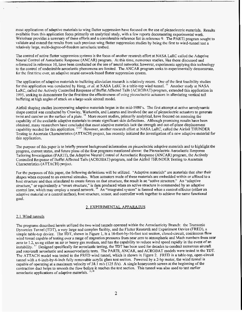
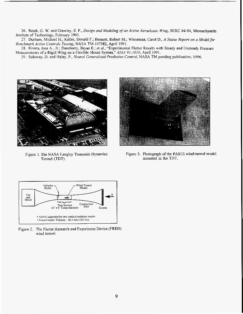
The programs described herein utilized the two wind tunnels operated within the Aeroelasticity Branch: the Transonic Dynamics Tunnel (TDT), a very large and complex facility, and the Flutter Research and Experiment Device (FRED), a simple table-top device. The TDT, shown in Figure 1, is a 16-foot-by-16-foot test section, closed-circuit, continuous flow wind tunnel capable of testing over a range of stagnation pressures from near zero to atmospheric and Mach numbers from near zero to 1.2, usiing either an air or heavy gas medium, and has the capability to reduce wind speed rapidly in the event of an instability. ” Designed specifically for aeroelastic testing, the TDT has been used for decades to conduct numerous aircraft and rotorcraft aeroelastic and aeroservoelastic tests. The PARTI, ANCAR, and ACROBAT models were tested in the TDT. The ATTACH model was tested in the FRED wind tunnel, which is shown in Figure 2. FRED is a table-top, open-circuit tunnel with a 6-inch-by-6-inch fully removable acrylic glass test section. Powered by a 2-hp motor, the wind tunnel is capable of operating at a maximum velocity of 38.1 m/s (125 Ws). A single honeycomb screen at the beginning of the contraction duct helps to smooth the flow before it reaches the test section. This tunnel was also used to test earlier aeroelastic applications of adaptive materials. ”*’’
2

2.2 Piezoelectric mater&
Piezoelectric materials, which develop a strain when subjected to an electric field and vice versa, are one of the most popular adaptive materials used today. Currently, these materials are divided into two groups, which differ by the direction that they are able to affect a host structure. The first group, commonly called strain actuators, exhibit an in-plane displacement capability. The second group is a new generation of actuators specifically designed to have an out-of-plane displacement capability.
The conventional configuration for an in-plane displacement piezoelectric actuator consists of a single piezoelectric wafer sandwiched between two electrodes. The relationship between an applied electric field and the corresponding behavior of a piezoelectric actuator is well documented. ‘6*18*19 Increased in-plane actuation can be obtained by several means, including grouping multiple wafers into multiple layers. An actuator possessing some out-of-plane displacement capability can also be created by stacking several of the in-plane piezoelectric wafers. 2o
Two of the new generation of piezoelectric actuators specifically designed to have an out-of-plane displacement capability are RAINBOW (Reduced And Internally Biased Oxide Wafer) Piezoelectric Driver and Sensor). Both devices have a monolithic structure and are pre-stressed during fabrication to set the direction of their displacement. RAINBOW, the first of these actuators to be developed, possesses 10 times the displacement capability of the in-plane actuators previously discussed. THUNDER, which was developed in house at NASA LaRC, exhibits an even larger displacement capability.
and THUNDER (Thin-Layer Composite-mimorph
2.3 Actuator selection methodolow
In general, the selection of an appropriate actuator for use with each program presented in this paper was based on four criteria: (1) bandwidth, (2) force, ( 3 ) displacement capability, and (4) ease of application. For flutter suppression and buffeting alleviation, bandwidth, force, and ease of application are the major criteria, and commercially available in-plane actuators suffice. However, for airfoil shaping, the driving criteria are force, displacement capability, and ease of application. Thus, out-of-plane displacement actuators, such as piezoelectric stacks, RAINBOW wafers, and THUNDER wafers, are typically used for this application.
3 . RESEARCH PROGRAMS
3.1 The Piezoelectric Aeroelastic Response Tailoring Investigation (PARTI) program
The Piezoelectric Aeroelastic Response Tailoring Investigation (PARTI) program was the first study in the area of aeroelastic control using adaptive materials to use a relatively large, multi-degree-of-freedom aeroelastic testbed. The PARTI program was a cooperative effort between the NASA Langley Research Center and the Massachusetts Institute of Technology. The objectives of this program were to demonstrate active control of aeroelastic response at subcritical speeds (conditions below the wing flutter speed) and wing flutter suppression using a large-scale aeroelastic wind-tunnel model with distributed piezoelectric actuators and to develop detailed experimental and analytical techniques. In this program, a wind-tunnel model was designed and fabricated, aeroservoelastic analyses were performed, and the model was ground and wind-tunnel tested in the TDT. As a result of this program, an extensive database of experimental information has been gathered that is instrumental in understanding the many issues associated with applying strain actuation technology to dynamic problems. The PARTI model was first tested in March 1994 to obtain basic flutter characteristics and transfer functions relating the model response to piezoelectric actuator input for various tunnel conditions. A closed-loop wind-tunnel test of the PARTI model was completed in November 1994. Preliminary results have been previously published regarding data collected during these tests. published. 24 Further discussion of wind-tunnel testing results and a discussion of experimental methodologies can be found in reference 25. The current paper will present a brief description of the PARTI model and wind-tunnel testing.
23 Analysis and design of several control laws along with preliminary test data have also been
3.1.1 Wind-tunnel model
The model is a five-foot long, high aspect ratio semi-span wing designed to flutter at low speeds to simplify aerodynamic analyses and wind-tunnel testing. The model consists of two primary structures: an exterior fiberglass shell used to obtain aerodynamic lift and an interior composite plate that contains the piezoelectric actuators and acts as the main load carrying member. The fully assembled model mounted in the TDT is shown in Figure 3. Figure 4 shows the interior construction of the model. The interior plate is composed of an aluminum honeycomb core sandwiched by graphite epoxy face sheets.
3

/-
The face sheets are of [-2Oo2/O0] laminate, referenced to the wing quarter-chord which is swept aft 30". The unsymmetric, unbalanced composite lay-up provides a static bendhwist coupling. The model has two additional components: a trailing- edge aerodynamic control surface and a wing-tip flutter-stopper device. The flutter-stopper tip-mass assembly was constructed as a safety device for wind-tunnel testing. Piezoelectric actuators cover the inboard 60% of the span of the internal composite plate and account for 7.3% of the total wing weight. Fifteen groups of piezoelectric actuator patches are adhered to the top and bottom of the interior plate. The actuators are configured to impart differential bending moments to the plate; however, the ply orientation of the graphite epoxy and the wing sweep angle make it possible for piezoelectric actuation to affect both the bending and torsion natural modes of the model. The piezoelectric patches were only used for actuation; ten strain gages and four accelerometers were used as sensors. The complete design of the PARTI model is documented by Reich and CrawIey. 26
3.1.2 Wind-tunnel testing
The PARTI model was ground tested and wind-tunnel tested during two entries in the TDT. Ground vibration tests were conducted to determine the dynamic characteristics of the model at zero-airspeed and to validate analytical models. Experimental flutter characteristics and open-loop time-history data at subcritical conditions were obtained during the first wind-tunnel test in March 1994. Time history data was acquired at several dynamic pressures by actuating each of the 15 groups of piezoelectric actuators individually as well as in five sets of several actuator groups. The open-loop data were used to construct state-space models for control law design, to examine the linearity of piezoelectric actuation, and to verify analytical models and techniques. A time domain system identification method was used to generate the state-space models from the time histories obtained during wind-tunnel testing. Using system identification, all of the PARTI model dynamics were fully captured using a math model with 120 states; however, state-space models with as little as 40 states were used as well. The open-loop data were also used to examine the linearity of piezoelectric actuation. Despite the presence of nonlinearities, the results indicate that superposition can be used to combine the responses of individual piezoelectric actuator groups. Furthermore, preliminary results show that there is a linear increase in model response with a linear increase in piezoelectric command voltage.
Twenty-eight control laws designed to increase flutter speed and reduce response at subcritical conditions were tested during the second wind-tunnel test. A variety of control law design techniques were used and both single-inputlsingle-output (SISO) and multi-input/multi-output (MIMO) control laws were designed utilizing up to five inputs and nine outputs. The PARTI model can be represented by up to 15 control outputs (1 5 groups of piezoelectric actuators) and 14 control inputs (1 0 strain gages and 4 accelerometers). However, several piezoelectric actuator groups receiving the identical output signal were considered as one control output. The most successful flutter suppression control law was also effective in reducing response at subcritical speeds, demonstrating a 12% increase in flutter dynamic pressure and a 75% reduction in the power spectral density of peak response at subcritical speeds as shown in Figures 5 and 6. This was a SISO control law that used all 15 piezoelectric actuator groups. Another SISO control law that used strain gage 4 for feedback and piezoelectric actuator groups 3,4, 6 ,7 , and 10 successfully increased flutter speed 8%.
The PARTI program successfully demonstrated active flutter suppression and reduced response at subcritical speeds using piezoelectric actuation on a five-foot span wind-tunnel model. Through this program, a number of issues associated with applying piezoelectric actuation to aeroelastic problems have been addressed; however, there exist several issues that require further study, some of which are planned as follow-on studies to the present research. These include an examination of scaling laws, power consumption, increasing control effectiveness through optimal actuator and sensor selection and placement, and the analytical development of state-space models.
3.2 AdaDtive Neural Control of Aeroelastic Response (ANCAR) Dromam
An important aspect in the development of a smart structure or integrated system is the corresponding development of an adaptive controller. The Adaptive Neural Control of Aeroelastic Response (ANCAR) program is a cooperative effort between NASA LaRC and McDonnell Douglas Aerospace to develop and demonstrate an integrated flutter suppression system that uses an adaptive neural network controller. The ANCAR program is comprised of three phases. Phases I and I1 use the LaRC Benchmark Active Controls Testing (BACT) wind-tunnel model. The Phase I objectives were to develop and demonstrate a hybrid control system that incorporated conventional control algorithms and neural networks to suppress flutter. Wind-tunnel testing for this phase took place in January 1995. The Phase I1 objectives are to develop and demonstrate an adaptive neural-network-based flutter suppression system during a January 1996 wind-tunnel entry. Phase I11 objectives are to combine the neural adaptive control system with an active structure like the PARTI model, Currently, wind-tunnel testing for this phase is scheduled for 1998. This section of the paper will focus on the results of Phase I and the plans for Phase 11.
4

3.2.1 BACT wind-tunnel mode I
The BACT model *' was originally developed as part of the Benchmark Models Program (BMP). *' The BMP was a NASA LaRC program that included a series of models which were used to study different aeroelastic phenomena and to validate aeroelastic, aeroservoelastic, and computational fluid dynamic methods in several wind-tunnel tests. Because the BACT model dynamics are well understood and it has control surfaces and relatively benign flutter mechanisms, it is an ideal testbed for initial testing of new control schemes, including neural-based systems.
The BACT model is depicted in Figure 7. The model is a rigid, rectangular wing with a NACA 0012 airfoil section. It is equipped with a trailing-edge control surface and upper- and lower-surface spoilers, all independently controllable. The model, shown in the figure, is attached to a mount system called the pitch-and-plunge apparatus (PAPA) that allows both pitch and plunge degrees-of-freedom. The model is extensively instrumented with pressure transducers and accelerometers to measure surface pressures and model dynamic response, and the mount system is instrumented with strain gages to measure normal force and pitching moment.
3.2.2 Phase I
The schematic for the Phase I neural network control system is shown in Figure 8. This is a hybrid control system that uses a neural network to gain schedule conventional control law parameters with varying Mach number and dynamic pressure. Figure 8 shows how the system was implemented. The neural network was trained to use Mach number and dynamic pressure as input and provide the coefficients of the control law as output. After conversion from continuous to discrete time, the control laws could be downloaded and run on a real time digital controller.
The neural network was trained by using fifty-six different state-space analytical models, each corresponding to a different combination of Mach number and dynamic pressure, which ranged from 0.3 to 0.9 and 75 psf to 250 psf, respectively. These models were used to generate fifty-six 3-zero and 4-pole, single-input/single-output control law designs, each optimized to achieve minimum RMS model response to tunnel turbulence. For each of the fifty-six control laws, there were 7 parameters that could be varied with Mach number and dynamic pressure, and a multi-layer perceptron neural network was trained with backpropagation to output these seven control law parameters as a function of Mach number and dynamic pressure. For comparison purposes, the same design strategy was used to generate a fixed-gain flutter suppression control law to provide the best possible performance over the whole flight envelope.
In the TDT, testing is accomplished easily and conveniently by frs t choosing a tunnel stagnation pressure and then varying drive motor RPM, which simultaneously changes Mach number and dynamic pressure. During Phase I testing, four different stagnation pressures were chosen, resulting in wide-ranging combinations of Mach number and dynamic pressure within the training space. Data was acquired at each of the four constant stagnation pressure conditions for the open-loop system, for the closed-loop fixed-gain system, and for the closed-loop neural-network-scheduled system. The RMS of the trailing edge accelerometer response for one of the stagnation pressures is shown in Figure 9. For this pressure, open-loop flutter occurs at a dynamic pressure of 161 psf. Here, the neural-network-scheduled system has the lowest response.
3.2.3 Phase I1
The goal of Phase I1 is to incorporate neural networks into adaptive flutter suppression systems. Unlike the Phase I controller, the Phase I1 neural systems will not use conventional control designs. Instead, they will adapt, on-line, to changing test conditions. A variety of adaptive neural-network-based systems will be tested during the January 1996 test. Several of the algorithms to be tested use a predictive control algorithm. Predictive control algorithms require generation of a math model for the system being controlled. Once the model is complete, the loop can be closed and a search or optimization algorithm can be used to select the control input commands that further minimize response over some time interval. In this application, a neural network is trained using experimental data acquired in the wind tunnel to create a neural model of the system that can be used to predict future responses to future control inputs. realization of predictive control is shown in Figure 10.
29 A neural network
This experimental study is investigating the use of neural networks for adaptive control of flutter with the BACT wind-tunnel model. During Phase I testing, a hybrid control system using a neural network to gain schedule conventional control law parameters was implemented for the first time, demonstrating slightly better flutter suppression than a fixed gain control system. Demonstration of an advanced neural network that can adapt to changing conditions is the goal for Phase 11.
5

3.3 The Activ elv Controlled Response of Buffet Affected Tails (ACRO BAT) p r m
The goal of the Actively Controlled Response of Buffet Affected Tails (ACROBAT) program was to demonstrate the feasibility of using active control for alleviating buffeting caused by leading edge extension (LEX) vortex burst. This phenomenon is shown in Figure 1 1. For this program, an existing 1/6-scale rigid full-span model of the F/A- 18 A/B aircraft was refurbished, and three new flexible and two new rigid vertical tails were fabricated. The model, shown in Figure 12, was tested during July 1995 and November 1995 with each of the new flexible tail surfaces at a Mach number of 0.09 in a test medium consisting of air at atmospheric pressure. The three flexible tails were fabricated from a l/S-inch thick aluminum plate and covered with balsa wood to produce the desired airfoil shape. The three flexible vertical tails used: (1) a rudder surface; (2) a tip vane configured with a slotted cylinder; 3) an embedded slotted cylinder; or (4) piezoelectric actuation devices. For the vertical tail with piezoelectric actuation, a hatch cover was incorporated in the design to cover the plate- mounted piezoelectric devices while maintaining the proper airfoil shape. The piezoelectric actuator arrangement itself, shown in Figure 13, consisted of three root actuators, two tip actuators, and two central actuators per side. Each of the tip and central actuators was comprised of two stacks of two layers of piezoelectric wafers, while each root actuator utilized two stacks offour layers for added effectiveness. The response of each flexible vertical tail was measured using a root bending strain gage and two tip accelerometers. Pressure transducers were surface mounted on both sides of all tails, excluding the tail with piezoelectric actuation.
3.3.1 Accomplishments
During the open-loop entry in July 1995, transfer functions were acquired for the response of the vertical tail to rudder (and buffet) inputs, to piezoelectric actuator (and buffet) inputs, to tip vane (and buffet) inputs, and to embedded cylinder (and buffet) inputs. Surface pressure data was also acquired. Based on the open-loop data, the rudder and the piezoelectric actuators appeared the most effective candidates. In addition to these open-loop measurements, several preliminary control laws were tested using the rudder, where in each case, the control law was designed using classical control methods. Data for several of these preliminary rudder-based control laws reduced the RMS response in the first bending mode by as much as 35%. This preliminary closed-loop result gave valuable insight into active buffeting alleviation for the November 1995 closed-loop entry. During the November entry, sixteen control laws were tested for the rudder while six control laws were tested for the piezoelectric actuators. Each control law reduced the power spectral density of the first bending mode by as much as 60% using gains well below the actuators’ physical limits. The results of one control law for the piezoelectric actuators are shown in Figure 14. Pressure measurements were acquired on both surfaces of the flexible and rigid vertical tails during numeraus open-loop and closed-loop conditions at various angles of attack.
The results of these wind-tunnel tests illustrate that buffeting alleviation of vertical tails can be accomplished using active control of the rudder or of piezoelectric actuators. A better understanding of control law design for active buffeting alleviation has been gained from this investigation. The pressure measurements offer insight into the flowfield around the tail during buffet. +
3.3.2 Future DlanS
Tests in the TDT to investigate potential adaptive control concepts for buffeting alleviation are planned for later this decade. In addition to wind-tunnel investigations, the United States Air Force (USAF) and NASA, through the auspices of The Technical Cooperative Program (TTCP), have initiated a collaborative buffeting alleviation study involving research organizations and industry from the United States, Australia, and Canada. The objective of this program is to ground test a full-scale F- 18 vertical tail that incorporates a buffeting alleviation system employing piezoelectric actuators. The ground tests are expected to be performed in Australia at the Aeronautical and Maritime Research Laboratory in Melbourne. Plans are to pursue a flight test demonstration of the concept at NASA Dryden Flight Research Center in 1999 if the ground test program proves successful.
3.4 Airfoil THUNDER Testing to Ascertain Characteristics (ATTACH) project
The Airfoil THUNDER Testing to Ascertain Characteristics (ATTACH) project was a feasibility study that focused on identifiing (1) the material characteristics, such as creep, hysteresis, and fatigue, and (2) the airfoil shaping effectiveness of the new THUNDER piezoelectric technology under aerodynamic loading. Characterization of the material behavior of THUNDER was the objective for Phase I, while Phase I1 examined its ability to reduce drag over an airfoil. The following sections present both the approach and preliminary findings of both phases of testing.
6

The testbed used for both phases of testing in the ATTACH project was the 0.25-inch thick, 1.5-inch wide, 5-inch long, generic, roughly-symmetric airfoil shown in Figure 15. This airfoil was supported by two 0.25-inch thick, IO-inch long sidewalls that extended through 85% of the length of the test section, creating a nearly two-dimensional flow condition. A single 1.5-inch wide, 2.5-inch long rectangular wafer of THUNDER was placed near the leading edge of the airfoil to act as the first half ofthe upper surface. To smooth the airfoiuwafer interface, a sheet of thin fiberglass material was wrapped over the upper surface of the airfoil/wafer combination and held in place by a flexible latex membrane. A photograph of the installed model is shown in Figure 16.
3.4.1 Phase I testing
The initial series of tests conducted during the ATTACH project were performed to identify the creep, hysteresis, and fatigue characteristics of a THUNDER wafer under aerodynamic loading. For this experiment, a total of 60 conditions were tested, consisting of combinations of the following parameters: five angles of attack (-2O, Oo, +2O, +4", + 6 O ) , four steady-state input voltages (-102 V, +lo2 V, -170 V, +170 V), and three tunnel velocities (wind-off, 20 m/s, 35 m/s).
The data obtained during this experiment conclusively identified the presence of both creep and hysteresis of the wafer under wind-on (loaded) and wind-off (unloaded) conditions. An example of wafer displacement in response to five cycles of applied voltage is shown in Figure 17. The test conditions were wind-off with the model at zero degrees angle of attack. In the figure, creep is characterized by the increasing positive (up) and negative (down) displacements exhibited by the wafer while under the constant applied voltages of +lo2 V, respectively. Hysteresis appears as the repeatable symmetric "loops," which in this case are: offset slightly due to creep. Figure 18 provides a comparison of the wafer displacement responses for the wind-off and 20 m/s conditions, again at zero degrees angle of attack. Creep and hysteresis are still apparent for the wind-on condition, but the presence of the flow contributes to smaller positive displacements (compared to wind-off) for the same applied voltage. Wafer displacements are smaller at lower tunnel velocities (not shown) and higher at higher angles of attack (also not shown).
During this phase of testing, the health of the wafer was frequently checked to gain a preliminary understanding of material fatigue. After two weeks of testing, the performance of the wafer began to noticeably degrade. During subsequent examination, no visible flaws were found, but a 33% drop in capacitance was discovered, and repoling returned the wafer to its full capabilities. Thus, similar to other piezoelectric adaptive materials, the performance of THUNDER appears to be a function of capacitance.
3.4.2 Phase I1 testing
With the objective of determining the ability of the THUNDER wafer to reduce drag over the airfoil, tests were conducted at the 40 wind-on conditions described above. For purposes of this feasibility study, it was assumed that variations in drag were directly proportional to velocity changes in the wake of the model. Comparisons of wake velocity for different test conditions, therefore, provided qualitative indications of the drag reducing potential of this piezoelectric actuator for this subscale model. Velocity measurements were taken by traversing a hot film anemometer velocity probe in 0.125-inch increments through the center of the test section sufficiently aft of the airfoil trailing edge to allow the wake to return to tunnel static pressure.
Results from this phase of testing were consistent with the results from Phase I. Velocity and angle of attack had the anticipated effect on drag. Positive applied voltages, which expanded the upper surface of the airfoil up to meet the flow, had the effect of reducing drag. Negative applied voltages produced the opposite effect. These results were obtained using only 32% of the maximum unloaded capability of the wafer. Thus, greater drag reductions would be expected if that percentage is increased.
The results of this research effort indicate that the new THUNDER actuator technology is a promising candidate for future airfoil shaping investigations. Despite decreases in the displacements of the wafer due to aerodynamic loading, noticeable drag reductions were obtained.
4. CONCLUDING REMARKS
This paper has presented brief descriptions of four innovative in-house research programs from the Aeroelasticity Branch at the NASA Langley Research Center. In these programs, adaptive materials and integrated systems are used for either active aeroelastic control or passive aerodynamic shape control. Active wing flutter suppression and reduction in wing response at speeds below flutter were demonstrated in the PARTI program using piezoelectric actuators. Demonstration of an integrated
7

flutter suppression system using adaptive neural network control is being studied through the ANCAR program. The ACROBAT program demonstrated reduced buffeting of the vertical tails of an F- 18 scale model using piezoelectric actuators and an active rudder. And the airfoil shaping potential of a new piezoelectric actuator technology called THUNDER was demonstrated in the ATTACH project.
5. REFERENCES
1 . Renken, J. H., “Mission - Adaptive Wing Camber Control Systems for Transport Aircraft,” AIAA-85-5006, AIAA
2. Szodruch, J. and Hilbig, R., “Variable Wing Camber for Transport Aircraft,” Progress in Aerospace Sciences, Vol.
3. Redeker, G.; Wichmann, G.; and Oelker, H. C., “Aerodynamic Investigations Toward an Adaptive Airfoil for a
4. Sandford, M. C.; Abel, I.; and Gray, D. L., Development and Demonstration of a Flutter Suppression System Using
5. Newsom, J. R. and Abel, I., Active Control of Aeroelastic Response, NASA TM-83179, July 1981. 6 . Waszak, M. R. and Srinathkumar, S., “Active Flutter Suppression: Control System Design and Experimental
3rd Applied Aerodynamics Conference, Colorado Springs, Colorado, October 14- 16, 1985.
25, pp. 297-328, 1988.
Transonic Transport Aircraft,” Journal of Aircraft, Vol. 23, No. 5, pp. 398-405, May 1986.
Active Controls, NASA TR R-450, December 1975.
Validation.” AIAA Pauer No. 91-2629. August 199 1 . v
7. Hwang, C.; Winther, B. A.; and Mills, G. R., Demonstration of Active Wing/Store Flutter Suppression Systems, AFFDL TR-78-65, June 1980.
8. Ashley, Holt; Rock, Stephen M.; Digumarthi, Ramarao; Chaney, Kenneth; and Eggers, Alfred J., Jr., Active Control for Fin Buffet Alleviation, WL-TR-93-3099, January 1994.
9. Weisshaar, T. A., “Aeroservoelastic Control with Active Materials - Progress and Promise,” Proceedings of the CEAS International Forum on Aeroelasticity and Structural Dynamics, Manchester UK, June 1995.
10. Lichtenwalner, P. F. and Little, G. R., “Adaptive neural control of aeroelastic response,’’ SPIE Vol. 27I7: Smart Structures and Integrated Systems, Publication pending.
1 1. Heeg, J.; Miller, J. M.; and Doggett, R. V., Attenuation of Empennage Buflet Response Through Active Control of Damping Using Piezoelectric Material, NASA TM- 107736, February 1993.
12. Crawley, E. F.; Warkentin, D. J.; et al., Feasibility Analysis of Piezoelectric Devices, MIT-SSL 5-88, Space Systems Laboratory, Massachusetts Institute of Technology, Cambridge, Mass., January 1988.
13. Leeks, Tamara J. and Weisshaar, Terrence A., “Optimization of unsymmetric actuators for maximum panel deflection control,” SPIE Vol. 2443: Smart Structures and Integrated Systems, pp. 62-74, San Diego, CA, February 27- March 3, 1995.
14. Weisshaar, Terrence A,, “Active Aeroelastic Tailoring with Advanced Materials,” 3 Ist Aircraft Symposium, pp. 34-45, Gifu, Japan, Nov. 10-1 1, 1993.
15. Layton, Jeffrey B., “An Analysis of Flutter Suppression Using Adaptive Materials Including Power Consumption,”
16. Weisshaar, T. A., “Aeroservoe~astic Control Concepts with Active Materials,” ASME International Mechanical AIAA-95-1191-CP, pp. 299-305, 1995.
Engineering Congress Exposition, Special Symposium on Aeroelasticity and FluidStructure Interaction Problems, Proceedings of the 1994 ASME Winter Meeting, November 1994.
17. The NASA Langley Transonic Dynamics Tunnel, LWP-799, September 1969. 18. Heeg. J., Analytical and Experimental Investigation of Flutter Suppression by Piezoelectric Actuation, NASA TP-
19. Crawley, Edward F. and Anderson, Eric H., “Detailed Models of Piezoceramic Actuation of Beams,” Journal of
20. Takahashi, Sadayuki., “Longitudinal Mode Multilayer Piezoceramic Actuators,” Ceramic Bulletin 65, The
2 1. Haertling, Gene H., “Rainbow Ceramics -- A New Type of Ultra-High-Displacement Actuator, ” American Ceramic
22. Hellbaum, Richard F., et al., Patent Application Number LAR15348- 1. 23. Heeg, J.; McGowan, A-M. R.; Crawley, E. F.; and Lin, C. Y., “The Piezoelectric Aeroelastic Response Tailoring
3241, March 1993.
Intelligent Material Systems and Structures, Vol. 1 ., pp. 4-25, January 1990.
American Ceramic Society, pp. 1 156-1 157, 1986.
Society Bulletin, Vol. 73, No. 1, pp. 93-96, January 1994.
Investigation: Analysis and Open-Loop Testing,” Proceedings of the CEAS International Forum on Aeroelasticity and Structural Dynamics, Manchester UK, June 1995.
Active Aeroelastic Wing,” Proceedings of the 36th AIAA/ASME/ASCE/AHS/ASC Structures, Structural Dynamics, and Materials Conference, New Orleans, LA, April 1995.
25. McGowan, Anna-Maria Rivas; Heeg, Jennifer; and Lake, Renee C., “Results From Wind-Tunnel Testing from the Piezoelectric Aeroelastic Response Tailoring Investigation,” Proceedings of the 1996 SDM Conference, Publication pending.
24. Lin, C . Y.; Crawley, E. F.; and Heeg, J., “Open-Loop and Preliminary Closed-Loop Results of a Strain Actuated
8
26. Reich, G. W. and Crawley, E. F., Design and Modeling of an Active Aeroelastic Wing, SERC #4-94, Massachusetts
27. Durham, Michael 14.; Keller, Donald F.; Bennett, Robert M.; Wieseman, Carol D., A Status Report on a Modeifor
28. Rivera, Jose A., Jr.; Dansbeny, Bryan E.; et al., “Experimental Flutter Results with Steady and Unsteady Pressure
29. Soloway, D. and Haley, P., Neural Generalized Predictive Control, NASA TM pending publication, 1996.
Institute of Technology, February 1993.
Benchmark Active Controls Testing, NASA TM- 107582, April 199 1 .
Measurements of a Rigid Wing on a Flexible Mount System,” AIM 9 / - f O / O , April 1991.
Figure 1. The NASA Langley Transonic Dynamics Tunnel (TDT).
Figure 3. Photograph of the PART1 wind-tunnel model mounted in the TDT.
Velocity Wind-Tunnel Probe Model
Test Section (6“ x 6” Cross-Section)
4 - Contraction Duct Screen
4irfoil supported by two vertical endplate inserts *‘Tunnel limits: Velocity - 38.1 m/s (125 ft/s) I
Figure 2. The Flutter Research and Experiment Device (FRED) wind tunnel.
9

Descnption of Supergroups
Supergroup Piezoelectnc Actuator (with group number)
8,11,12,14,15 - 2 9,10,13
1,2,3,4 - 3 n 4
1/4 Chord Swept 30"
Aerodynamic Shell Section
Figure 4. Drawing of the major components on the PARTI wind-tunnel model.
I 5 10 15 20 25 lo.'o t
Frequency ~
Figure 5 . Results of subcritical response tailoring: Power spectral density functions.
Mode 1 Mode2
Closed loop
frequency Natural Hz
.Y- 12%
0 1 I 50 60 70 76 80 85 90 100
Dynamic pressure psf
Figure 6. Comparison of natural frequency migration for open-loop and closed-loop systems.
10

I ,-
WACAM12
Acrclcrornctrn
Ai~cma _. .... .. . ..I *... ... -...... , lz,l Spailcn
b- :-\-e-, - c - ’-
Figure 7. BACT wind-tunnel model.
A.
L. W l S
Neural Network
t
Figure 10. Neural network realization of predictive control.
Figure 8. Neural-network-scheduled flutter suppression system.
Figure 1 1. Flow visualization of LEX core breakdown.
0.050
0.040
0.030 Trailing
Edge Acceleration 0*020
0.010 W s ) , g‘s
0
I Open-Loop d Wn-Loop Stable Unstable
0 Fixed-Gain Controller
A Neural-Network Scheduled Controller
120 140 160 180 200
Dynamic Pressure, psf
F :j 9. Comparison of neural-network-sc gain closed-loop systems and the
Figure 12. li6-scale F/A-18 A/B model installed in the TDT.

Figure 16. Photograph of the ATTACH model in FRED.
Figure 13. Piezoelectric actuator configuration.
PET1 Closed loop +
,,*----- --e 1.1) -
.:3 - PSD (at first
of root strain actuauon (normalized). (gain = 100) ,,,'
bending ,,s - ,,a'
' /'" /-,,--- frequency) Piezoelectric
E?/HZ 0' .'Z -
0 ' 20 26 30
Anele of attack. deerees
0.6
0.4
Displacement, mm 0
-0.4 -o.21 -0.6 I I I I I I I
-150 -100 -50 0 50 100 150 Applied
Voltage, V
Figure 14. Buffeting alleviation results second entry (November 1995): first bending mode.
Figure 17. Typical wafer displacement pattern in response to five cycles of applied voltage (+/- 102 V).
Generic 1 airfoil (symmetric)
Figure 15. ATTACH testbed.
0.8 r I 7 Initial Displacement
7 Final Displacement
0.6
0.4
0.2
mm 0
-0.2
Displacement,
-0.4 I I I I I I 1
Applied Voltaee. V
-150 -100 -50 0 50 100 150
Figure 18. Changes in wafer displacement due to aerodynamic loading.
12