controlled cavitation-cell interaction: trans-membrane ...cdohl/publication/pmb08.pdf · controlled...
TRANSCRIPT

1
Controlled cavitation-cell interaction: trans-membrane transport and viability studies
Rory Dijkink*, Séverine Le Gac #, Erwin Nijhuis§, Albert van den Berg#, István Vermes¶, André Poot§, and Claus-Dieter Ohl*, ||
*Physics of Fluids, Faculty of Science and Technology, University of Twente, PO Box 217, 7500 AE Enschede, The Netherlands. #BIOS The Lab-on-a-Chip group, Faculty of Electrical Engineering, Mathematics and Computer Science, MESA+ Institute for Nanotechnology, University of Twente, PO Box 217, 7500 AE Enschede, The Netherlands. §Polymer Chemistry and Biomaterials Group, Faculty of Science and Technology, University of Twente, PO Box 217, 7500 AE Enschede, The Netherlands. ¶Department of Clinical Chemistry, Medical Spectrum Twente Hospital Group, PO Box 50000, 7500 KA Enschede, The Netherlands. ||Division of Physics and Applied Physics, School of Physical and Mathematical Sciences, Nanyang Technological University, 637616 Singapore. Tel.: +65-6513-8039; Fax: +65-6794-1325; E-mail: [email protected] Keywords: cavitation, sonoporation, adherent cells, drug delivery, apoptosis

2
Summary Cavitation bubble dynamics close to a rigid surface gives rise to a rapid and transient fluid flow. A single bubble is created with a laser pulse at different stand-off distances from the rigid surface, where the stand-off distance γ is defined by γ = h / Rmax with h the initial distance and Rmax the maximum bubble radius. When the surface is covered with adherent cells, molecular delivery and cell detachment after single cavitation activity are observed at different locations. We find a maximum of cell detachment at a normalized stand-off distance of γ ~ 0.65. In contrast, the maximum of the molecular uptake is found when γ approaches 0. The single cavitation event has only little effect on the viability of cells in the non-detached area. We find apoptosis of cells only very close to the area of detachment and, additionally, the metabolism of the non-detached cells shows no pronounced difference compared to control cells according to an MTS assay. Thus, although the cavitation event is responsible for the detachment of cells, only few of the remaining cells undergo a permanent change.

3
Introduction The effect of continuous and weak wall shear stress on adherent cells and their biological pathways is well documented in literature [1]. For higher flow velocities in the bulk the wall shear stress increases and this eventually leads to the detachment and transport of cells with the flow. A transient and strong flow allows the exposure of cells to high levels of shear yet without their detachment. Recently, it was observed that this regime of short but high wall shear stress facilitates the uptake of non-membrane permeant molecules into the cells [2]. This finding might allow for developing strategies for the delivery of foreign and large molecules into cells. The necessary fast and transient flow is created with a cluster of vapor bubbles induced with an acoustic wave. By aiming the focused acoustic source close to a surface plated with adherent cells, bubbles can be generated in the vicinity of the cells. The bubbles expand rapidly within a few tens of microseconds to radii of 200μm and above [2]. During the accelerated shrinkage of the bubbles being close to the cell-supporting surface the fluid flow is concentrated into a jet directed towards this surface [3-5]. This jet flow impacts onto the surface and then spreads radially on top of the adherent cells. With increasing radial distance from the point of jet impact on the surface we find cell detachment, cell death, and molecular delivery. It is known that the size of the bubble and its distance from the boundary strongly affects the magnitude and duration of the flow close to the surface where the cells reside [4, 6]. Unfortunately, when vapor bubbles are nucleated with acoustic waves there is no control on the distance of the bubble with respect to the wall [7] and little on the number density and distance between bubbles [8]. The uncontrolled nature of this type of cavitation exposure to cells causes poor repeatability of the experiment. Thus, we were not able to quantify the molecular uptake and the viability of the cells after the bubble activity in our previous studies [2] with respect to the bubble dynamics. This experimental shortcoming is now solved by utilizing a laser pulse to create a single bubble [9] close to the adherent cells. The usage of a focused laser pulse allows for controlling the start of the bubble pulsation, its position, and its maximum size. This method enables parameter studies on the fluid dynamics and the effect on cells. In detail we report here on the radius of the cell detachment, cell morphology, molecular delivery, cell viability, and induction of apoptosis. All of the data presented are from well-controlled and repeatable experiments involving a single cavitation event. The work is organized as follows: firstly, the experimental set-up to generate and photograph single cavitation events is presented. Secondly, cell cultivation, staining, confocal laser microscopy, and the viability MTS assay are introduced. In the results section we give an overview on the details of the bubble dynamics and related flow phenomena. Subsequently, the cell-detachment area and the amount of molecular uptake as a function of the stand-off distance are discussed. This section is succeeded with biological relevant studies on cavitation-induced apoptosis and cell viability. In the discussion the origin and the importance of the high speed flow generated close to the boundary on the observed biological effects are emphasized.
4
Materials and Methods
Experimental set-up to create single cavitation bubbles Single millimeter sized cavitation bubbles are created by focusing pulsed laser light into a liquid. Therefore, we use an infrared Nd:YAG laser (New Wave Solo, Fremont, Ca, USA) at the fundamental wavelength of 1064 nm with a pulse duration of 7 ns and a pulse energy of approximately 16 mJ. The laser light enters a cuvette from the top through an aberration minimized lens system, see Fig. 1. The cuvette is filled with cell culture medium (Iscove’s modified Dulbecco’s medium, see below). The lens system is partly submerged and attached to a z-positioning stage. Thereby, the distance between the laser focus where the bubbles are created and the surface covered with adherent cells can be precisely adjusted. Adherent cells are plated onto the bottom surface of open 8-well plates arranged on a single microscope slide (µ-Slide 8 well, ibidi, Martinsried, Germany) which is submerged into the cuvette. This procedure allows, due to geometrical constraints, cavitation experiments in the central 4 wells while keeping the chamber slide submerged. The remaining outer wells are used as controls. All walls (cell culture chambers, bottom of the cuvette and its side walls) are transparent to facilitate visual control and recording. Therefore, the set-up is equipped with two cameras. A double frame camera (Sensicam QE double shutter, PCO, Kehlheim, Germany) allows viewing from the side as illustrated in Fig. 1 to record the position of the bubble with respect to the cell layer. The second camera, a digital 4 megapixel still camera, is connected to the camera port of the inverted microscope (Axiovert CF 40, Zeiss, Goettingen, Germany) supporting the cuvette, and is used for fluorescence imaging.
Cell culture and preparation for cavitation experiments Epidermal HeLa cells (derived from human cervix carcinoma) are grown in Iscove's modified Dulbecco's medium supplemented with 10% of fetal calf serum (FCS) and 1% antibiotic-antimycotic (all supplements are obtained from Invitrogen, Breda, The Netherlands). Cultures are performed in a humidified incubator with a temperature of 37°C and a CO2 level of 5%. Tissue culture equipment is purchased from Nalge Nunc (Fisher Scientific B.V, Landsmeer, The Netherlands). Prior to the experiments, cells were seeded into the 8-well plates and grown overnight in an incubator to allow attachment of the cells to the surface and subsequent to reach an exponentially growing cell population. When 80-90% cell confluency per well was obtained experiments were performed. The 8-well plate is gently submerged into the tank filled with serum-free and pre-heated culture medium.
Cell staining and imaging
Cell staining: Calcein We investigate cell membrane permeabilization using the small fluorescent molecule calcein (623 mol wt; maximum absorption at wavelength λexc= 490 nm and wavelength at maximum emission λem= 515 nm) (Merck, Darmstadt, Germany). Calcein at a

5
concentration of 1 mg/ml in medium is gently injected into the wells after the slide has been submerged into the non supplemented culture medium. After the cavitation experiment, the cells are thoroughly but also carefully washed with fresh medium to remove the remaining calcein which causes a high level of background fluorescence.
Three-dyes cell staining We study apoptosis using three cell staining dyes giving information on the cell state, namely TMRE (TetraMethylRhodamine Ethyl ester, perchlorate) (λexc= 550 nm; λem= 590 nm), Annexin V-Alexa Fluor 647 (λexc= 650 nm; λem= 665 nm) and YOPRO-1 (λexc= 491 nm; λem= 509 nm) (all from Molecular Probes, Invitrogen, Breda, The Netherlands). Cell staining is performed in a calcium-enriched medium (2.5 mM CaCl2) (calcium is required for binding of Annexin V to phosphatidylserine, PS) supplemented with the dyes at the concentrations of 300 nM, 0.5 % v/v and 500 nM for TMRE, Annexin V-Alexa Fluor 647 and YOPRO-1, respectively. We investigate two approaches (see Results section); (i) either we wash cells and add fresh culture medium supplemented with calcium and the dyes after the cavitation experiment or (ii) we perform the experiments in a calcium-enriched culture medium (the tank was filled with calcium-enriched but not supplemented culture medium) and add the dyes at the end of the experiment.
Fluorescence microscopy We use a microscope (Axiovert CF40, Carl Zeiss, Göttingen, Germany) with a 5x objective to photograph the calcein uptake. Fluorescence is excited with a mercury lamp (HBO 50, Carl Zeiss) and observed with an appropriate filter block (No. 09, Carl Zeiss, band pass BP excitation filter 450 nm < λ < 490 nm, long pass LP emission filter λ>510 nm).
Confocal laser scanning microscopy (CLSM) Confocal laser scanning microscopy is performed on a Zeiss LSM 510-meta system. Excitation and filters are as follows: TMRE, λexc= 543 nm, LP 560 nm; Alexa Fluor 647, λexc= 633 nm, LP 650 nm; YOPRO-1, λexc= 488 nm, BP 500 nm - 550 nm. A multi-track configuration is used in case of imaging with several dyes. Laser intensity is decreased to limit photo-bleaching; it is set at 5%, 4% and 10 % of the maximum for 488 nm, 543 nm, and 633 nm, respectively.
Image analysis The size of the bubble and its distance from the wall are determined from pictures taken during the maximum expansion with the side viewing camera. The size of the cell depleted area is measured with image processing techniques. For this, bright field illumination of the individual wells gave the best contrast. The position of the laser focus is determined from bright continuum emission of the plasma. The magnification of the picture is obtained from geometrical features of the individual plastic wells. Calcein uptake is measured from the fluorescent micrographs taken with a still color camera. After suitable image processing the area in each picture with positive cells (green fluorescent) and the average level of dye uptake as a function of the radial distance from

6
the projected laser focus are determined. Image processing is done with the MATLAB/IP toolbox (The Mathworks, Natick, MA, USA).
MTS assay Cell viability after exposure to a cavitation event is assessed through an MTS (3-(4,5-dimethylthiazol-2-yl)-5-(3-carboxymethoxyphenyl)-2-(4-sulfophenyl)-2H-tetrazolium, inner salt) assay. Directly following the cavitation experiment wells are washed. MTS is added according to the CellTiter 96 AQueos 96 proliferation assay protocol (Promega, WI, USA) 1 h before recording the absorbance. It should be noted that when the reagent is added without washing the wells (i.e. removing the medium where the experiment is performed) the redox reaction on which the MTS assay relies is hindered. This is thought to be due to a high amount of chemicals that are released in the medium due to cell lysis and necrosis upon exposure to the cavitation bubble. The MTS cell proliferation assay was performed 0, 2, 4 and 24 h after cavitation exposure. During this time the plates were incubated at 37°C and 1 h before recording the absorbance the MTS reagent was added. The MTS reagent is converted by dehydrogenase enzymes in metabolically active cells into soluble formazan whose absorbance is read at 492 nm using an automated Victor plate reader. This absorbance value is directly proportional to the amount of viable cells. Similar measurements are concomitantly conducted on control cells that have also undergone the same treatment, i.e. seeded in 8-well chambers, taken out of the incubator for a while, submerged into the same growth medium, but not exposed to cavitation bubbles.
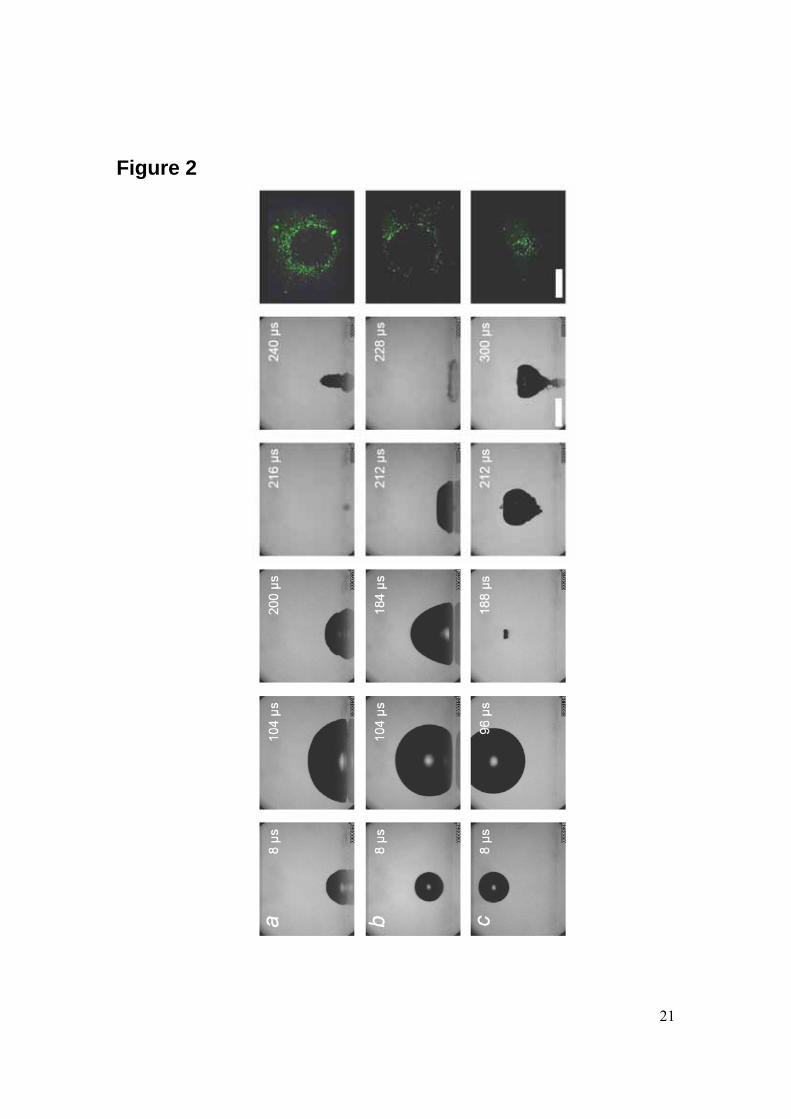
Results The usage of a laser to create single cavitation bubbles allows exposing adherent cells to a reproducible controlled flow. One of the important experimental parameters for the cavitation-cell interaction is the distance between the bubble center and the substrate on which the cells were grown. This so-called stand-off distance γ is defined by γ= h / Rmax where h is the initial distance of the bubble center to the wall and Rmax the maximum radius of the bubble. In the potential flow limit bubbles with the same stand-off distance exhibit similar dynamics. Three examples of the bubble dynamics for different stand-off distances are presented in Fig. 2. Here, the distance of the bubble nucleation point from the boundary is increased from top (Fig. 2a) to bottom (Fig. 2c) and for each distance 5 frames from a high speed sequence have been selected. Fig. 2a depicts a bubble very close, stand-off distance γ = 0.1, to the boundary which is at the lower part of the individual frames. Here, the bubble expands resembling nearly a hemisphere; it shrinks, and then collapses at about 200 µs after its creation. During re-expansion the bubble develops into a cigar shape upwards directed structure. When the bubble is created at some distance away from the boundary, see Fig. 2b with γ = 0.9, the upper side of the bubble again expands into a spherical shape, whereas the lower side facing the boundary is flattened. During shrinkage the bubble obtains an approximate triangular shape in projection and a jet flow is generated starting from the
7
top more curved part of the bubble and being accelerated towards the boundary. The jet flow is not visible in this sequence but responsible for the toroidal bubble in the last frame of the high-speed sequence of Fig. 2b. Here, after the impact and spreading of the jet flow, a vortex ring is generated, which stabilizes the re-expanding bubble into a torus. In contrast, the jet flow becomes, although indirectly, visible in the sequence at the largest stand-off distance γ = 2.0. The bubble expands and collapses almost spherically; yet again a thin and fast jet flow is created which is visualized by the shape of the re-expanding bubble on top of this jet flow. The jet flow causes the cusp shape at the lower bubble side, and the jet impacts around t = 300 µs on the surface. Additionally, the bubble moves towards the boundary and presumably, the second collapse of the bubble (not shown here) takes place on the boundary. It has been observed that detachment of cells occurs after the jet has impacted on the wall [2, 7] and that the cells are washed away during the radial spreading of the jet on the surface. Thus, it is expected that the velocity of the jet at impact is an important parameter for cell detachment. Further, it has been found that the detachment region continues to grow even after the bubble has ceased. It is very probable that the later detachment is caused by a vortex ring fed by the jet flow. From simple arguments the jet impact velocity must possess at least one global maximum between γ = 0 and γ = ∞: A bubble collapsing very far from the boundary will not develop a jet or the jet has died out before it reaches the wall. A bubble which expands as a hemisphere, γ = 0, will –due to symmetry reasons– not develop a jet flow. Indeed, the measurements of Philipp and Lauterborn [10] show a maximum impact velocity at a stand-off distance of γ ~ 0.7. Thus, as we assume that the detachment and the impact velocity of the jet are correlated we would expect a maximum in the detachment area for γ ~ 0.7 as well.
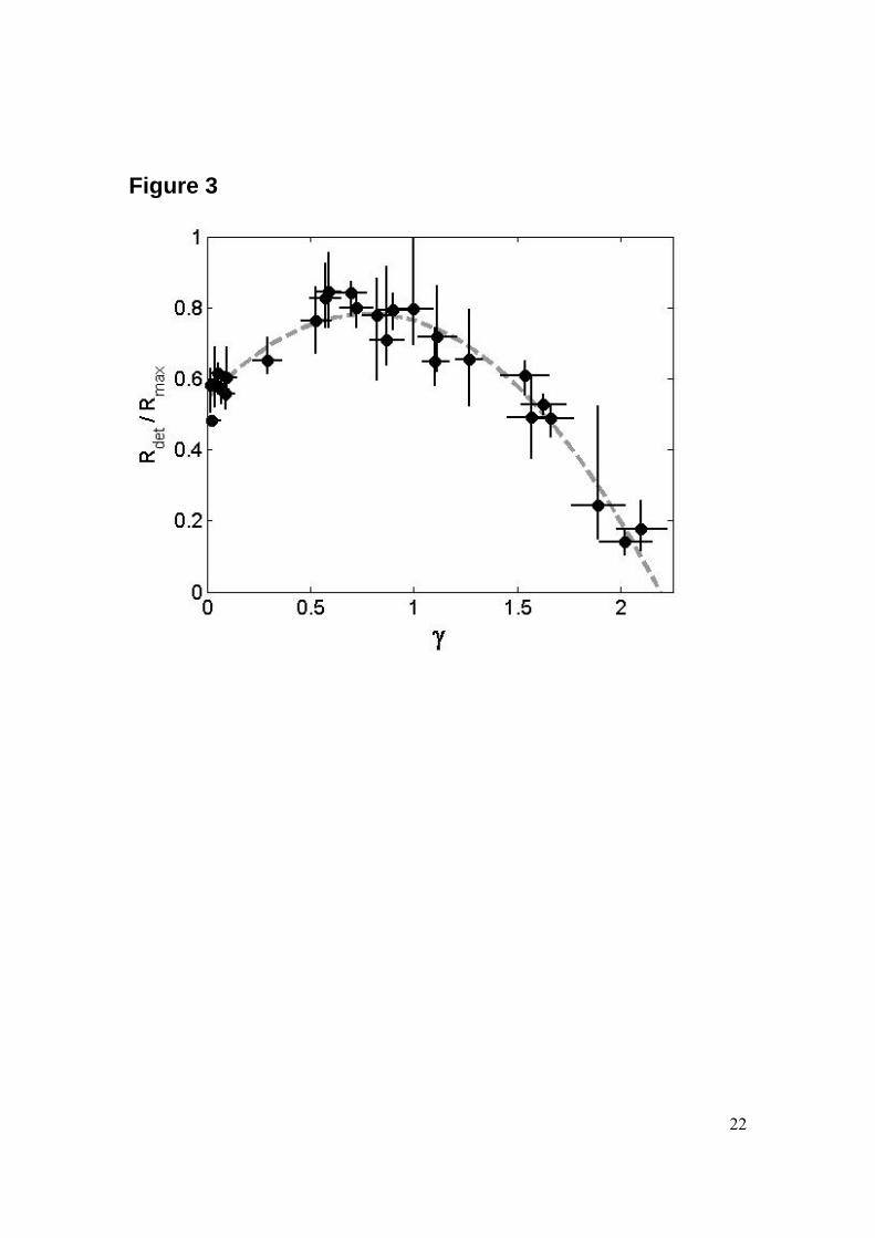
Area of cell detachment We find no cell detachment for stand-off distances larger than γ > 2.0. Therefore, the reported γ values in this work are limited to the range between 0 and 2.0. All the bubbles have an average maximum radius of 1.0 mm ± 15%. The three fluorescent micrographs in Fig. 2 illustrate the areas of cell detachment together with the high-speed sequence as a function of the stand-off distance. When the bubble is created far from the cell layer little or no cell detachment is observed. With decreasing distance the cell detachment area increases. Interestingly, the detachment area reaches a maximum at γ ~ 0.65, and then the area decreases again yet to a finite area as γ approaches 0. The reproducibility in this experiment is demonstrated by the scatter in the data points in Fig. 3 e.g., we achieve a reproducibility of the detachment radius of 10-20%. The radius of the detachment area for small stand-off distances is in the order of the maximum bubble radius Rmax, which is in agreement with the findings in our previous work [2]. Interestingly, both the detachment area and the impact velocity of the jet obtain a maximum at approximately the same stand-off distance of γ ~ 0.7. This agrees with the previous findings of Junge et al. [7] and Ohl et al. [2, 11] that the jet is responsible for a strong boundary layer flow able to detach the cells. Interestingly, detachment is still found for γ ~ 0 thus when no flow-focusing phenomenon is expected. Here, presumably the boundary layer breaks the

8
symmetry of the hemispherical inflow during the last collapse phase and a net flow from the top prevails which might be responsible for the observed cell detachment.
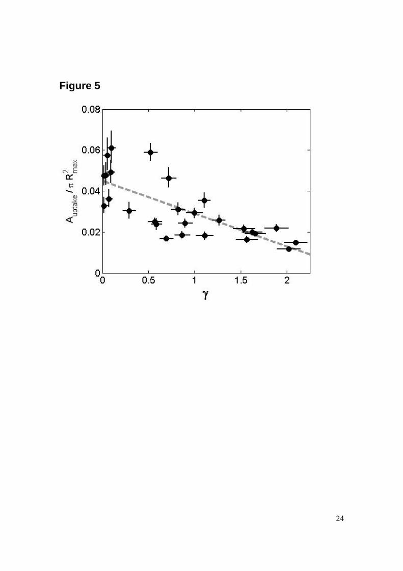
Molecular delivery into cells Next, we investigate the cavitation induced uptake of foreign molecules through the cell membrane. This uptake is probed with the fluorescent molecule calcein (623 Da, Stokes-radius 2-3 nm) which is added to the medium before the cavitation event. After cavitation exposure cells are carefully washed and the calcein uptake quantified with fluorescence microscopy. The patterns of molecular uptake for the three representative stand-off distances γ = 0.1, 0.9, and 2 are depicted besides the corresponding bubble series in Fig. 2. The green fluorescence originates from the interior (cytoskeleton) of the adherent HeLa cells. Thus, the laser induced cavitation bubble is able to porate the cell membrane very similar to shock-wave induced cavitation. From the pictures as shown in the right of Fig. 2 we quantify the uptake with two methods. For both of the methods the geometrical center of the uptake area is determined first and then the fluorescent intensity distribution is measured as a function of the radial distance while averaging over the angle. The radial distribution of the calcein uptake is shown in Fig. 4 for various stand-off distances. Please note that the height of each curve is rescaled e.g., their amplitude does not reveal the integrated intensity. Calcein positive cells are found on a ring surrounding the detachment area, i.e. uptake is found for cells being exposed presumably to the highest levels of wall shear stress while remaining attached. The width of the ring of calcein uptake varies with the stand-off distance: the closer the bubble is generated to the boundary the wider the ring of uptake. What is the optimum stand-off distance for molecular uptake? An answer to this question is given in Fig. 5 by plotting the total area of calcein fluorescence for various γ-values; this area is normalized by the cross-section of the bubble. Although the scatter of the data is large a clear trend is visible: with decreasing stand-off distance more cells show uptake. This negative trend is supported by a Spearman rank correlation coefficient of -0.77. Maximum uptake is found for bubbles closest to the cells, i.e. for γ = 0 and the uptake decreases with increasing distance. In contrast to the finding of a maximum of the detachment at γ ~ 0.65, we find monotonically increasing uptake when the bubble is created closer to the cells. The absolute value in Fig. 5 however should be read with care for a few reasons: firstly, not the whole cell is fluorescent but only some fraction of it. Secondly, though confluence is constant it is not taken into account in this measurement and last, low levels of fluorescence may be lost by applying a threshold in the image analysis. Thus, the number of cells affected can not be directly read from the area of uptake.
Cavitation induced cell death It is reported in Ohl et al. [2] that cell death (ethidium bromide positive cells) occurs at the edge of the detached region. The question remains whether cell death is necrosis or apoptosis-type and whether deep into the non detached cell layer late apoptosis is induced. Effects on cell viability and especially the induction of apoptosis have been reported for cancerous human lymphocytes exposed to cavitation bubbles driven with a continuous ultrasound wave [12].

9
Here, for the study of apoptosis fluorescent compounds are used and for quantitative analysis of cell metabolism an MTS assay is employed. For this study and the below reported MTS assay we fixed the stand-off distance of the bubble to γ ~ 1. The fluorescent staining agents for the apoptosis studies consist of a set of three apoptotic and viability markers which allow for detecting cell death and for distinguishing between apoptosis and necrosis. The first marker is a mitochondrial staining, TMRE (or TetraMethylRhodamine Ethyl ester, perchlorate) which is dependent on the inner mitochondrial membrane potential. Healthy cells are positive to TMRE, whereas they become TMRE-negative when entering apoptosis as a result of the depolarization of the inner membrane of the mitochondria. Later in the process of apoptosis, the phospholipid composition of the cell membrane changes, notably with the externalization of phosphatidylserine (PS) which is targeted by the second marker, Annexin V-Alexa Fluor 647 (13, 14). The third dye is a nuclear probe, YOPRO-1 that enters cells only after disruption of their membrane (in late stages of apoptosis). By using these three dyes, we can distinguish between viable cells (TMRE-positive), cells entering apoptotis (TMRE-negative), early apoptotic cells (Annexin V-positive) and late apoptotic cells (Annexin V and YOPRO-1 positive). In a first step, we wash cells after the cavitation experiment, place them in a calcium-enriched medium supplemented with the three dyes and image them using CLSM. Cells are found TMRE-positive both in the control samples and in the treated wells except close to the detachment area. In the zone surrounding the detachment area, cells are round-shaped and some of them start to detach. Moreover, cells in this area become positive to both Annexin V and YOPRO-1, indicating apoptosis. It is important to mention that dead cells that have detached from the surface and float in the medium are removed upon washing and replacing the medium. Not to loose the free-floating cells dying directly upon exposure to the bubble we decided to carry out a second series of experiments without washing the cells at the end of the cavitation experiment but by directly using calcium-enriched culture medium and to only add the three dyes after the cavitation experiment. As depicted in Fig. 6, the amount of cells positive to both Annexin V and YOPRO-1 increases and are randomly dispersed in the well, both on the detached area as well as above the viable cells, as these dead cells are free to move in the solution. Apoptosis is mainly detected at the border of the detachment area and not in cells further away. This is visible in Fig. 6 by the two-colored ring located around the detachment area detected by confocal microscopy. Using the same procedure (without washing) we image cells over time at one particular location at the border of the detachment area for 3 h (starting circa 30 min after the cavitation experiment) with a 10 min interval between pictures. Two confocal microscope images have been selected in Fig. 7 depicting the area 30 min and 3 h after the cavitation event. It shows the increasing number of apoptotic cells as time passes. At the beginning, Fig. 7 top, mainly Annexin V-positive cells are found, whereas the amount of YOPRO-1-positive cells increases in the first hours. The shape of the cells evolves as well, blebs become larger and hollow structures into which apoptotic cells leak appear, see Fig. 7 bottom. Both the morphology of the cells (eg. blebbing) and the consecutive staining with Annexin V and YOPRO-1 characterize these cells as apoptotic and not necrotic. In the case of necrosis the cell membrane and nucleus are permanently porated and cells
10
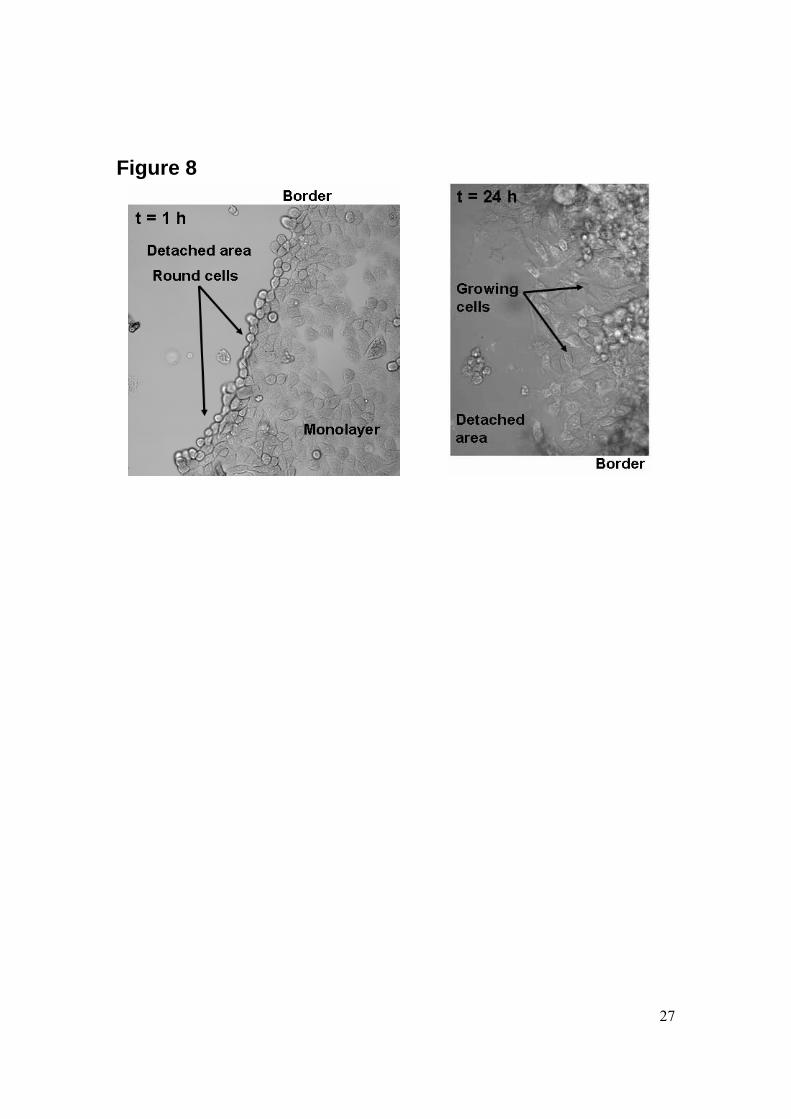
become simultaneously positive to Annexin V and YOPRO-1. Furthermore, necrosis is instantaneous and no cell blebbing, which is characteristic for apoptosis, takes place. We perform time–lapse imaging up to 24 h after the cavitation experiment. After 24 h, not significantly more dead cells are found (data not shown). Also, cells located close to the detachment area grow again and adopt a flat and stretched shape, which is demonstrated in Fig. 8. This indicates that cell growth is not inhibited by the cavitation event. In this figure cells located close to the detachment area are compared 1 and 24 h after cavitation exposure; the two pictures reveal that cells adopt a round shape just after the cavitation event whereas they reshape back to a monolayer flat morphology one day after the experiment. Longer monitoring of cell-viability is not feasible due to the limited size of the wells. In summary we see that cell death occurs by apoptosis and mainly close to the spot where the bubble is created. Moreover, cell death is observed within a few hours after the cavitation event but no further cellular changes are observed after 2-3 h.
Cell viability Viability of HeLa cells after their exposure to a single bubble is concomitantly assessed using an MTS assay over a time-window of 24 h so as to determine whether cells are functioning properly or whether they have been impaired by the cavitation event. This is compared to control samples, plated in similar microchambers but not submitted to a cavitation event. Fig. 9 presents the results as averaged values for formazan absorbance (for 4 independent samples) for both series of samples (treated and control) at 0, 2, 4 and 24 h. These values are corrected for the amount of cells in each well and therefore take into account the 5% loss of cells observed directly after the cavitation event (detachment area). These detached cells are removed by washing the samples prior to addition of the MTS reagent. From the data presented in Fig. 9 we can conclude that the overall viability of cells within two hours after exposure to a cavitation event is comparable to that observed in the control wells. A small decrease in cell viability (1-5 %) is subsequently observed for the treated samples (at 4 and 24 h); this can be explained with the apoptosis of cells in the direct vicinity of the detachment area. The incidence that a single cavitation bubble has on a monolayer of HeLa cells with respect to the cell viability is in good agreement with the data collected using CLSM techniques that show a small increase in apoptosis within a few hours following the cavitation event close to the location of bubble oscillation whereas the overall amount of dead cells remains constant at longer time-scales (e.g., 24 h). The initial lower abundance measured for formazan production, at t = 0, that shows a lower metabolic activity of cells just after the experiment for both the control and treated samples can be explained by the stress these cells have undergone: they have been taken out of the incubator and their medium has changed. After two hours, the cells have recovered as indicated by the higher metabolic activity.
Discussion
Regions in the monolayer of cell-bubble interaction After exposure to a cavitation bubble the monolayer of cells can be divided in four distinct regions. The first region is located directly below the center of the bubble and corresponds to the spot of jet impact and radial spreading. In this region cells are

11
suddenly detached. The second region is located around the detachment zone and consists of a 1-3 cell wide ring where cells die on a time-scale of 1-2 h. These cells have greatly experienced the jet-induced flow but they have yet not been detached, and as a result become porated in a permanent way, causing apoptosis. In an earlier study we found, when fixing the cells within a few minutes after the cavitation exposure, large pores in SEM pictures of those cells [2]. The third zone is composed of cells which are porated but to a lesser extent and in a transient way. This region is the area where viable drug delivery occurs. The fourth zone consists of the rest of the monolayer and is composed of cells which are unaffected by the cavitation event; they are located too far away from the bubble induced flow. We assume that the pore size and/or the number of pores in the membrane decrease with increasing distance of the cells from the bubble center. Cells located very close to the bubble (region 1 and 2) are literally perforated; they are lysed or die by apoptosis. Cells located in region 3 are also porated but pores are smaller or less frequent, and they enable the entry of foreign substances (region 3) or are too small for that. It might be possible to decide if either the number of pores or the size of the pores decreases with distance by using particles of different sizes with different fluorescent markers and evaluate their uptake pattern as a function of the distance from the jet impact.
Cell death As already mentioned, exposure to a cavitation event leads to cell death in given zones in the monolayer. Either immediate cell lysis or slow apoptotic death is observed 1-3 h after cavitation exposure in the first ring of cells around the detachment area. On a longer time-scale no further change is observed and remaining cells are observed to be viable and functioning properly according to the MTS assay. Moreover according to confocal studies cells in region 2 die by apoptosis and not by necrosis as indicated by the Annexin V-positive staining. This finding is similar with the reported cell death following ultrasound exposure with microbubbles [15]. However, it is not clear in the ultrasound experiments if similar but smaller scale bubble dynamics is present, see also van Wamel et al. [16]. Sonoporation leads to death of cells according to two mechanisms, either by lysis [17, 18] or apoptosis [19]. If in vivo cell killing is the goal, then apoptosis would be the preferred modality as fewer immune reactions are expected from the organism while cell lysis evokes an inflammatory response [20]. In our experiments, we observe apoptotic bodies floating in solution (data not shown); this demonstrates that cells are detached from the surface upon bubble expansion and collapse as suggested by Ohl and Wolfrum [21]. Yet, cell lysis can not be excluded especially for cells close to the stagnation point. Indeed, first attempts to carry out an MTS assay without washing have not been successful; our hypothesis is that the medium was full of chemicals released by cells and that these compounds hinder the redox reaction on which the MTS assay is based. Consequently, although cells die by apoptosis we cannot exclude lysis for cells from the detached area.
Correlation with wall shear stress exposure Our main assumption is that the cavitation-induced flow strains the adherent cells which leads to pore creation in their membranes and consequently to the uptake of molecules
12
from the surrounding fluid into the cell’s cytoplasm. Although this study does not reveal the dynamics of cell membrane straining, the obtained results are supported by this general picture of a fluid mechanical induced forcing of the cell membrane. The second observation, namely cell detachment, is found for bubbles collapsing close enough to the boundary, γ ≤ 2. A maximum of the detached area is found for γ = 0.65. Interestingly, it has also been reported that the highest jet impact velocities are occurring between 1 and 0.5 [10]. This finding suggests that detachment of the cells might be correlated with the impulsive flow from the spreading of the wall jet. Unfortunately, the fluid dynamics driven by the cavitation bubble is considerably more complex e.g., the bubble collapses multiple times, a translation of the bubble center towards the wall occurs, a long lasting vortex ring is created. Still, considering that the detachment is caused by the first and most violent jet impact we can give an estimate of the wall shear stress occurring. The fluid dynamics of the wall spreading jet has been studied using an analytical solution, the Glauert solution [22] for a steady and laminar wall jet. For the convenience of the reader we repeat here equation (7) of Ref. [2]):
4/1
11
3
0 216125
⎟⎟⎠
⎞⎜⎜⎝
⎛=⎟⎟
⎠
⎞⎜⎜⎝
⎛∂∂
== x
Fyu
y νρρντ , (1)
where the constant ( ) 43128/1 jetjet duF = allows an estimate of the wall shear stress at the border of the detached region. The variables and parameters in Eq. (1) are u the bulk velocity tangential to the wall, ρ the density of the liquid, ν the kinematic viscosity, and ujet and djet the speed and diameter of the jet, respectively. For γ = 0.65 with a jet velocity at impact of vjet = 70 m/s (see e.g., Fig. 3d Ref. [10]) and a jet diameter of 1/10 of the maximum bubble diameter Rmax = 1.0 mm the wall shear stress at the edge of the detached region (at 0.8 mm from the stagnation point) the Glauert solution predicts approximately 30 kPa for the wall shear stress. Although, this value seems very large it is of the same magnitude as reported by Rau et al. [18]. There, the wall shear stress estimated during the bubble expansion which causes cell lysis ranged between 60 kPa and 220 kPa. We want to mention that in both approaches [2, 18] a rigid wall with no slip is assumed and this overestimates the wall shear stress when the surface is covered with deformable cells. The number of cells showing molecular uptake increases with decreasing the stand-off distance, which is in contrast to the area of detached cells. Again, we expect that the wall shear stress is the important contribution to the trans-membrane transport. Yet, only cells in a certain range of exposure conditions show uptake. For too high or too long lasting shear, the cell will become detached and too little shear does not affect the cell membrane. Here, the results indicate that not only the jet but other flow features contribute to the pore formation. High levels of wall shear stress can be generated not only by the spreading jet flow, but also by the expanding/collapsing bubble interface –when the bubble is close enough to the boundary [18]. If we come back to the experiments conducted by Venugopalan’s and Vogel’s group [18, 23, 24], they report on cell lysis already occuring during the rapid expansion of the bubble. In this case a hemispherical bubble is created on top of the wall supporting the cells e.g., the bubble’s stand-off distance is about γ = 0. Yet, the mechanisms for bubble-cell interaction are similar: the bubble accelerates the fluid close to the boundary to a high velocity which leads to strong shear in the boundary layer where the cells reside.
13
The timing when the shear is generated is different: in the latter experiments by Venugopalan’s and Vogel’s group the explosive expansion and in our experiments and as reported by Ohl et al. [2] during the spreading of the jet. In summary the following scenario is suggested. When the bubble oscillates far from the boundary, γ > 2 approximately, the jet flow is too weak to create sufficient shear once it impacts on the boundary. In the intermediate regime, approximately 0.5 < γ < 2, the jet impacts with sufficient strength such that the radial spreading leads to the most important contribution. In this regime the bubble is too far from the boundary to harm the cell membrane by its rapid expansion. However, when the bubble is generated closer to the boundary, approximately 0 < γ < 0.5, the expansion (and presumably also the collapse) of the bubble dominates while the jet flow strength decreases and vanishes for γ ~ 0.

14
Conclusion and Outlook We have demonstrated drug delivery in a monolayer of HeLa cells by means of a single cavitation bubble created in close vicinity to the surface covered with cells. The findings are in agreement with our previous work [2], however now a more controlled and single bubble system is used. The advantage is that we have control over the position of the bubble with respect to the cells. The efficiency of the drug delivery process depends on the stand-off distance at which the bubble is created with respect to the wall: the closer the bubble to the wall the higher the yield, together with little cell loss by cell detachment. Moreover, the studies of cell fate and viability after exposure to a single cavitation event demonstrate that cells survive the cavitation event, although a small amount of cells located just at the border of the detachment area die by apoptosis within a few hours. This apoptotic ring is a few cells wide. The four regions of bubble-cell interaction are the result of a particular (time averaged) strength and a certain exposure duration. Thus one might ask if an optimum exposure condition exists for which viable trans-membrane transport can be achieved without inducing apoptosis. To answer this question, the measurements of the wall shear stress have to be conducted to obtain its magnitude and its function of time. With this knowledge possibly cells grown in microfluidic channels could be exposed to a mock flow field with similar wall shear stress features. Thereby, the flow induced drug delivery is optimized and made available for a larger number of cells. Because it is expected that the wall shear stress for uptake and apoptosis differs with cell type, it might be possible to differentiate between cells using different hydrodynamic exposure conditions.
Acknowledgements We thank Theo W. Driessen and Jelle Storteboom for help with the experiments. This work is funded by NWO (The Netherlands) through a VIDI grant.

15
References
1. Li, Y.J., J.H. Haga, and S. Chien. 2005. Molecular basis of the effects of shear stress on vascular endothelial cells. J. Biomech. 38:1949-1971.
2. Ohl, C.D., M. Arora, R. Ikink, N. de Jong, M. Verlsuis, M. Delius, and D. Lohse.
2006. Sonoporation from Jetting Cavitation Bubbles. Biophys. J. 91:4285-4295.
3. Blake, J.R., G.S. Keen, R.P. Tong, and M. Wilson. 1999. Acoustic cavitation: the fluid dynamics of non-spherical bubbles. Philos. Trans. R. Soc. Lond. A. 357:251–267.
4. Lindau, O., and W. Lauterborn. 2003. Cinematographic observation of the
collapse and rebound of a laser-produced cavitation bubble near a wall. J. Fluid Mech. 479: 327-348.
5. Zeff, B.W., B. Kleber, J. Fineberg, and D. Lathrop. 2000. Singularity in curvature
collapse and jet eruption on a fluid surface. Nature (27th January 2000) 407:401-404.
6. Brujan, E.A., G.S. Keen, A. Vogel, and J.R. Blake. 2002. The final stage of the
collapse of a cavitation bubble close to a rigid boundary. Phys. Fluids. 14:85–92.
7. Junge, L., C.D. Ohl, B. Wolfrum, M. Arora, and R. Ikink. 2003. Cell detachment method using shock-wave-induced cavitation. Ultrasound Med. Biol. 29:1769–1776.
8. Arora, M., C.D. Ohl, and D. Lohse. 2007. Effect of nuclei concentration on
cavitation cluster dynamics. J. Acoust. Soc. Am. 121:3432-3436.
9. Vogel, A., W. Lauterborn, and R. Timm. 1989. Optical and acoustic investigations of the dynamics of laser-produced cavitation bubbles near a solid boundary. J. Fluid. Mech. 206:299-338
10. Philipp, A., and W. Lauterborn. 1998. Cavitation erosion by single laser-produced
bubbles. J. Fluid Mech. 361:75-116.
11. Ohl, C.D., M. Arora, R. Dijkink, V. Janve, and D. Lohse. 2006. Surface cleaning from laser-induced cavitation bubbles. Appl. Phys. Lett. 89:074102.
12. Feril Jr., L.B., T. Kondo, Z. Cui, Y. Tabuchi, Q. Zhao, H. Ando, T. Misaki, H.
Yoshikawa, and S. Umemura. 2005. Apoptosis induced by the sonomechanical effects of low intensity pulsed ultrasound in a human leukemia cell line. Cancer Letters 221:145-152.

16
13. Vermes, I., C. Haanen, H. Steffensnakken, and C. Reutelingsperger. 1995. A novel assay for apoptosis—Flow cytometric detection of phosphatidylserine expression on early apoptotic cells using fluorescein-labeled annexin-V. J. Immunol. Methods 184:39 –51.
14. Le Gac, S., I. Vermes, and A. van den Berg. 2006. Quantum dots based probes
conjugated to annexin V for photostable apoptosis detection and imaging. Nano Lett. 6:1863-1869.
15. Feril Jr. L.B., T. Kondo, Q.L. Zhao, R. Ogawa, K. Tachibana, N. Kudo, S.
Fujimoto, S. Nakamura. 2003. Enhancement of ultrasound-induced apoptosis and cell lysis by echo-contrast agents. Ultrasound Med. Biol. 29:331-337.
16. van Wamel, A., K. Kooiman, M. Harteveld, M. Emmer, F.J. ten Cate, M.
Versluis, and N. de Jong. 2006. Vibrating microbubbles poking individual cells: Drug transfer into cells via sonoporation. J. Controlled Release 112:149-155.
17. Kondo, T., Y. Fukushima, H. Kon, and P. Riesz. 1989. Effect of shear stress and
free radicals induced by ultrasound on erythrocytes. Arch. Biochem. Biophys. 269:381-389.
18. Rau, K.R., P.A. Quinto-Su, A.N. Hellman, and V. Venugopalan. 2006. Pulsed
laser microbeam-induced cell lysis: time resolved imaging and analysis of hydrodynamic effects. Biophys. J. 91:317-329.
19. Ashush, H., L. A. Rozenszajn, M. Blass, M. Barda-Saad, D. Azimov, J. Radnay,
D. Zipori, and U. Rosenschein. 2000. Apoptosis induction of human myeloid leukemic cells by ultrasound exposure. Cancer Research 60:1014-1020.
20. Muoz-Pinedo, C., D.R. Green, and A. van den Berg. 2005. Confocal restricted
height imaging of suspension cells (CRISC) in a PDMS microdevice during apoptosis. Lab Chip 5:628-633.
21. Ohl, C. D., and B. Wolfrum. 2003. Detachment and sonoporation of adherent
HeLa-cells by shock wave-induced cavitation. Biochim. Biophys. Acta Gen. Subj. 1624:131–138.
22. Glauert, M. B. 1956. The wall jet. J. Fluid Mech. 1:625–643.
23. Vogel, A., P. Schweiger, A. Frieser, M. N. Asiyo, and R. Birngruber. 1990.
Intraocular Nd:YAG laser surgery: light-tissue interaction, damage range, and reduction of collateral effects. IEEE J. Quantum Electron. 26:2240–2260.

17
24. Rau, K.R., A. Guerra, A. Vogel, and V. Venugopalan. 2004. Investigation of laser-induced cell lysis using time-resolved imaging. Appl. Phys. Lett. 84:2940–2942.
18
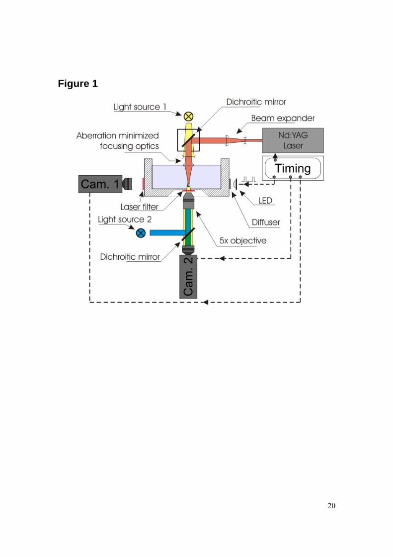
Figure Legends Figure 1: Experimental set-up used to generate single laser-induced cavitation bubbles close to adherent cells. The cavitation bubble is generated with an infrared laser pulse coming from the top into the medium-filled container and focused with a lens system. The upper dichroic mirror reflects the laser pulse but lets pass some light for illumination from the top. Cameras 1 and 2 record the bubble dynamics from aside and below, respectively. Side illumination is achieved with a bright light-emitting diode. Cells are grown in 8-well plates on a slide which is positioned on the transparent bottom of the container. An Hg lamp is also placed below the container for fluorescence measurements; this light source is used to excite the cells that have taken up a fluorescent dye. Figure 2: Series of frames showing the collapse of a cavitation bubble for various stand-off distances and illustrating the influence of the stand-off distance on the bubble oscillation regime and the calcein uptake (last picture on the right). (A) γ = 0.1, (B) γ = 0.9 and (C) γ = 2.0. Pictures are taken from the side using a high-speed camera (250kfps) starting from the creation of the bubble at time 8 μs. The rigid boundary is located at the bottom of the individual frames. The two bars both with a length of 1 mm display that both the frames from the high-speed recording and the fluorescence have the same magnification. Figure 3: Plot of the averaged non-dimensionalized radius Rdet/Rmax of the cell detachment area (πR2
det) as a function of the stand-off distance γ. The filled circles are individual experiments and the dashed line is a fitted parabola with a correlation coefficient of 0.95. The error in the detachment radius is obtained from the variations in the radius of the detached area along the circumference. The averaged maximum bubble radius is 1.0 mm ± 15%. Figure 4: Fluorescence intensity pattern as a function of the distance from the projected center of the bubble (normalized by the maximum radius of the bubble Rmax) for various stand-off distance values γ. For each stand-off distance the zero fluorescence baselines are vertical and the signal represents the integrated fluorescence signal averaged over the angle. In average the maximum bubble radius is 1.0 mm ± 15%. Figure 5: Plot of the measured area (normalized by the cross-section of the bubble at maximum radius, πRmax
2) with calcein uptake as a function of the stand-off distance γ. The error in the measured area of uptake was obtained by varying the threshold value during image analysis by ± 10% from. Additionally, we performed a rank correlation test (Spearman) which gives a correlation coefficient of -0.77, supporting the large negative correlation between the stand-off distance and the uptake area. The dashed line is linear least square fit to the data. The averaged maximum bubble radius is 1.0 mm ± 15%.
19
Figure 6: Reconstituted picture of the detachment area and its surrounding part, showing the four zones on the surface. Cells are stained with the set of three markers for detecting apoptosis after exposure to the cavitation bubble. TMRE (red) stains viable cells, while blue (Annexin V-Alexa Fluor 647) and green (YOPRO-1) stain dead cells. TMRE-positive cells are found everywhere in the monolayer but in the detached area (zone 1) and just around it (zone 2), where cells have been affected by the cavitation bubble. Annexin V- and YOPRO-1-positive cells are found floating in the medium above the monolayer and the detached area as well as the border of the detachment area (zone 2) where cells are dying at a slow time-scale. Figure 7: Two views from a time-lapse imaging sequence recorded at the border of the detachment area illustrating changes in cells and apparition of apoptosis as a result of the cavitation bubble induced flow. In both views the cells are stained with 3 dyes, TMRE, Alexa Fluor 647 (coupled to Annexin V) and YOPRO-1. The upper view was taken 30 min after exposing the cells to the cavitation event. At t = 30 min, there are a few dead cells at the center of the viewing area (enlarged in insert 2) and at the left (insert 1). After 2 h (data not shown), a new group of dead cells appear right to the center. Also blebbing structures, characteristic for apoptosis, appear on the cytoplasmic membrane in these three groups of cells. 3 h after the cavitation event the blebs become larger (inserts 1 and 2). Also DNA staining is shown by the bright spots illustrating the condensation of chromatin and fragmentation of the DNA inside the nucleus. Figure 8: Enlarged views of the border of the detachment area. Left: 1 h after exposure to the cavitation bubble the cells along the detachment area obtain presumably due to the loss of most of their focal adhesion points a rounded shape. Right: 24 h later, the cells grow again into the former cell-denuded area and posses a flat shape. Figure 9: Cell viability and metabolic activity assessed through a MTS assay. Samples were taken at t = 0, 2, 4 and 24 h for cells exposed to a cavitation bubble (gray) (at t = 0) and for control cells (white) that underwent the same treatment except from the exposure to a cavitation event. Data correspond to the absorbance intensity measured at 492 nm for the production of formazan by cells; these values have been averaged over 4 samples and are corrected for the amount of cells remaining in the wells (i.e. they take into account cell detachment following the cavitation event).
20
Figure 1
21
Figure 2
22
Figure 3

23
Figure 4
24
Figure 5

25
Figure 6

26
Figure 7
T = 30 minTMRE
YOPRO-1Annexin V-Alexa Fluor 647
27
Figure 8

28
Figure 9