controlled cooling of drop forged …imim.pl/files/archiwum/vol1_2011/11.pdfsion and chassis...
TRANSCRIPT

A R C H I V E S O F M E T A L L U R G Y A N D M A T E R I A L S
Volume 56 2011 Issue 1
DOI: 10.2478/v10172-011-0011-2
P. SKUBISZ∗, H. ADRIAN∗, J. SIŃCZAK∗
CONTROLLED COOLING OF DROP FORGED MICROALLOYED-STEEL AUTOMOTIVE CRANKSHAFT
KONTROLOWANE CHŁODZENIE ODKUWEK MATRYCOWYCH WAŁU KORBOWEGO DO SAMOCHODU
Certain aspects of determination of continuous cooling conditions directly after forging and their applicability to industrialconditions are discussed. On example of high-pressure-pump crankshaft problems concerning realization of drop forging ofmicroalloyed-steel forged shaft with thermomechanical treatment involving subsequent direct controlled cooling are presented.
The paper is focused on determination of both forging conditions and subsequent cooling parameters, which in combinationwith modelling of precipitation kinetics in the analysed steel allowed accomplishment of required final mechanical propertiesof the forged part. For the determined conditions of thermomechanical treatment experimental trials in industrial conditionswere carried out. Obtained in simulation pattern of continuous cooling was realized with a line consisting of six stages ofcontrolled rate of stirred air flow. Satisfactory level of mechanical properties, exceeding minimum of the assumed requirementswas reported, as well as uniform fine grained microstructure regardless of cross-sectional dimensions, meeting the requirementsof automotive industry.
Keywords: thermomechanical treatment, controlled cooling, drop forging, mechanical properties, numerical modelling,hardness, ductility
Przedstawiono niektóre zagadnienia dotyczące doboru warunków kontrolowanego chłodzenia odkuwek matrycowychbezpośrednio po kuciu i ich stosowalności w warunkach przemysłowych. Na przykładzie odkuwki wału korbowego pompywysokociśnieniowej samochodu osobowego przedstawiono próbę zastosowania obróbki cieplnoplastycznej z uwzględnieniemwarunków technologicznych jej realizacji dla odkuwek ze stali z mikrododatkami.
W pracy skupiono się na określeniu zarówno warunków kucia matrycowego, jak również parametrów bezpośredniegochłodzenia z temperatury kucia, co w połączeniu z modelowaniem kinetyki wydzielania pozwoliło na uzyskanie założonychfinalnych własności mechanicznych odkuwki. Dla określonych drogą modelowania numerycznego warunków obróbki ciepl-noplastycznej przeprowadzono weryfikację doświadczalną w warunkach przemysłowych, przy wykorzystaniu specjalnej liniido ciągłego chłodzenia, składającej się z kilku stref chłodzenia z kontrolowaną szybkością. Wykonane próby przemysłowezapewniły uzyskanie wymaganego poziomu własności mechanicznych i plastycznych odkuwki, a tym samym potwierdziłyzasadność przyjętych warunków technologicznych.
1. Introduction
Manufacture of structural elements for high-dutyapplications forces an incessant pursuit of good me-chanical properties without a negative impact oncost-effectiveness of production. The tendency of light-weight structure oriented design, attaining high perfor-mance triggers the needs for improvement of steels char-acterized by high strength, high yield stress, crack re-sistance and good weldability [1, 2]. This is especiallytrue for the automotive industry, where production ofhigh-duty parts, such as transmission systems, suspen-sion and chassis components or crankshafts induce eco-
nomical and environment friendly manufacture process.In fact, this can be accomplished by means of eitherthe development of new grades or improvement in thetechnology.
Direct cooling has become a commonly used al-ternative for traditional quenching-tempering method oftreatment of steel products, offering good combination ofstrength and ductility at significant costs savings, hencefinding increasing number of applications in automotiveapplications [3, 4]. Additions of alloying elements andcontrolled processing depending on a synergic combi-nation of plastic deformation and heat treatment is now
∗ AGH – UNIVERSITY OF SCIENCE AND TECHNOLOGY, FACULTY OF METALS ENGINEERING AND COMPUTER SCIENCE FOR INDUSTRY, 30-059 KRAKÓW, 30 MICKIEWICZA AV.,POLAND

94
a common way of reducing manufacturing costs to im-prove mechanical properties of a forged part [5, 6].
Efforts to introduce Nb into steel for hot-rolledsheets gave rise to development of important groupof microalloyed steel, important for technical and eco-nomical reasons [7]. Benefits of microadditions in steelwere fully revealed in High Strength Low Alloy steels(HSLA). Their final properties are provided directly afterdeformation process as a result of controlled cooling [8].Nowadays direct-cooled steel parts can attain typicallyferrite-pearlite, bainite, martensite or various types ofbainite-martensite structures [6]. These days controlledcooling is well implemented both for stationary process-es, such as rolling, and also for impression-die forg-ing of parts of relatively uniform cross-sections, but formore complex shapes of forgings, the control of criti-cal process parameters call for more considerations. Inorder to bring about proper run of transformation kinet-ics favourable distribution of thermo-mechanical para-meters before start of cooling must be provided, as wellas, appropriate rate of cooling in varying in dimensionssections of forged part.
The first tests of air-cooling directly fromhot-working temperature date back to the seventies,which resulted in producing so-called 1st generation mi-croalloyed steels. The most common steel of this group,49MnVS3 – a medium-carbon steel with vanadium ad-ditions, was used for manufacture of responsible compo-nents such as crankshafts. Despite relatively high level ofstrength, hardness of those steels was relatively low. Toincrease hardness silicon in content of 0,5% was addedand simultaneously carbon was reduced to 0,38÷0,27%.These additions were also to improve weldability andcastability. The decrease in strength was compensatedwith high manganium (>1%), with minor content of ni-trides and carbides forming elements. In following yearsnew steels group was developed, giving rise to so called2nd generation of microalloyed steels. Steel 38MnSiV5may be referred to as a representative of this group [3,4]. Since then, constant development in this field hasbeen witnessed, with steel precipitation hardened duringcontrolled cooling directly from the deformation tem-perature. Vast majority of application of these gradesinvolved hot-rolling processes, while forging processes,on account of more complex determination of processparameters, were not so common [9, 10].
These days “SiV” steels are produced, which ex-hibit high strength and hardness, as well as goodcrack resistance and weldability associated with low car-bon content. These are ferrite-perlite steels. Currently,contribution of products made of microalloyed steelsin well-developed countries reaches 50% of the totalamount of steel used in automotive industry and still an
ever-increasing tendency is observed [8]. It is estimatedthat utilization of these sort of steels with thermome-chanical processing in the manufacture of automotiveforged parts brought manufacture savings of about 20%.What is more, structural components of HSLA steel, ascompared to traditional structural steels, can bear thesame loads at smaller cross-sections.
To benefit from thermomechanical treatment (TMT)in a forging process some technological setbacks mustbe overcome. They arise from diversity of shapes andsizes of forged parts, which calls for the necessity ofdetermination unique forging and cooling process para-meters. Mechanical properties of forged parts made ofmicroalloyed steels are obtained by proper determina-tion of forging process conditions, such as preheatingtemperature, forging temperature, dwell time and timeof intervals between consecutive operations, as well ascooling conditions after drop forging operations. Anotherimportant issue is determination of preheating tempera-ture, which must provide good forgeability as to obtaindesired geometry at minimum number of blocker im-pressions and, on the other hand, appropriate tempera-ture from the microstructure standpoint; keeping some ofcarbides undissolved and preventing from grain growth[11].
The mechanical properties of forged componentsmade of microalloyed steels are obtained by proper de-termination of forging process conditions, such as pre-heating temperature, forging temperature, dwell time andtime of intervals between consecutive operations, as wellas cooling conditions after the forging operations havebeen completed. Another important issue is determina-tion of preheating temperature which must provide goodforgeability as to obtain desired geometry at minimumnumber of blocker impressions and, on the other hand,appropriate temperature from the microstructure stand-point; keeping some of carbides undissolved and pre-venting from grain growth.
As-forged material condition is reflected by the con-dition of microstructure resultant from strain distribu-tion and temperature gradients in the volume. The na-ture of the forging process itself introduces additionalvariables which contribute to possible nonuniformity ofobtained microstructure after forging. For complex parts,some sections significantly differ in thickness, causingboth nonuniform distribution of deformation and localincrease in strain rate, and in result, significant amountof deformation heat. Complex geometry produces a met-al flow pattern resulting in completely different time ofcontact of deformed metal with tool surface. Althoughthe temperature differences diminish during subsequentstages before cooling, such as trimming operation, in the

95
aftermath of the temperature and strain gradients, localdifferences of microstructure occur.
In the work, the possibility of utilization thermo-mechnaical treatment is investigated on the exampleof drop-forged high-pressure pump crankshaft of steel38MnSiVS6. To take advantage of the benefits offeredby combination of microalloyed steel application and uti-lization of heat attained after forging an estimation ofactual temperature profile and strain gradients in char-acteristic cross-sections of the part is necessary. For thisreason numerical calculations of the whole forging andcooling cycle is needed, which in combination with theknowledge of included in numerous literature sourcesdata on precipitation kinetics form a sort of input datafor controlled cooling process parameters.
2. Objective and assumptions
The subject of the work are issues associated withselection of conditions of controlled cooling and process
parameters which enable technological realization ofthe determined time-temperature-deformation regime indrop forging process with subsequent direct cooling. Theaim of the research was determination of forging processconditions, which in combination with theoretically esti-mated cooling rate, based on calculation of precipitationkinetics, would provide required final mechanical proper-ties of forged parts made of medium carbon microalloyedsteel.
Steel used in the study was to meet final propertiesrequirements typical of automotive high-pressure pumpcrankshaft that is: UTS 820 MPa, TYS 550 MPa, elon-gation 12% and area reduction at fracture 22%. For theneeds of experiment, special heat was cast. Detailedcomposition of the heat used in experiment, which isfurther referred to as 38MnSiVS6, is shown in Table 1.On account of diversified cross-sections and relativelysimple geometry allowing for one-stage forging, crank-shaft of geometry presented in Fig. 1 was selected to theresearch.
TABLE 1Chemical composition of the 38MnSiVS6 steel heat used in the experiment
Element C Si Mn P S V Al
Content, % 0.36 0.56 1.35 0.008 0.055 0.08 0.012
Fig. 1. Geometry and dimensions of the analysed crankshaft forging
Despite relative complexity in geometry of the part,varying in transverse dimensions (Fig. 1) it was assumedthat complete fill-up of die impression involve minimumforging stages and throughout the whole length of thepart length uniform degree of deformation in produced
in each of characteristic cross-section. Determination ofthe forging conditions was based on numerical calcula-tions of the forging process. Of fundamental importancehere was an estimation of appropriate start-of-forgingtemperature and the geometry of the billet, which in con-

96
nection with forging equipment kinematics would resultin determined temperature of end of forging. For easiercontrol of the temperature changes and temperature gra-dients on the cross-section due to cooling on tool andbetter reproducibility of samples, it was decided to usefinish-only die impression to complete the deformationin a single blow.
As the forged shaft was meant to undergo controlledcooling directly after forging, the key issue is to providefavourable course of cooling curves in each section of thepart by means of end-of-forging temperature and coolingrate. To obtain the required rate of temperature decreaseensuring thereby proper run of precipitation process, nu-merical modelling with use of finite element method wascarried out.
Also an investigation of process conditions whichaffect the mechanical properties after thermomechanicaltreatment were carried out by means of numerical sim-ulation, including both forging process and subsequentcooling. The investigation in the forging operations wasaimed at getting favourable distribution of deformationand temperature profile at the end stage of forging, toprovide optimal initial conditions of direct cooling. Witha use of obtained temperature and strain levels as in-put data multistage direct cooling was simulated to cuecooling curves pattern for transformation and precipita-tion kinetics. Hence, having obtained proper temperatureprofile after forging, cooling curves in the characteristiccross-sections of the forged part were plotted for vari-able cooling rates. In result, correlation between coolingrate in cross-sections concerned and calculated coolingmedium flow rate was obtained.
Designed time-temperature regime of direct coolingwas afterwards verified experimentally. The controlledcooling was realized in continuous manner in a spe-cial tube-alike cooling line containing six cooling zones,which made it possible to independently control coolingintensity in each of them in order to obtain unique tem-perature regime in consecutive cooling stages. Temper-ature measurement was done with pyrometers mountedat each of the cooling stations.
The process of impression-die forging to a degreegives some freedom of selection of process conditions.In aspect of thermomechanical treatment by direct cool-ing the most crucial parameters are resultant distribu-tions of temperature and strain. However, from techno-logical standpoint, the most suitable level of temperatureand/or amount of deformation often calls for additionalchanges, which are sometimes hard to accept on accountof forging process economy or machines capacity limi-tations.
For the analysed crankshaft the forging temperature(forging billet preheat) in traditional process involvingmedium carbon steel is normally held at about 1200◦C toprovide plasticity and tool life. However, working speedof used mechanical press of 0.5÷0.8 m/s produces ex-cessive amount of deformation heat in areas of largereduction. In conventional technology that makes littleproblem as final properties are formed with subsequentquenching-tempering (Q&T) heat treatment, contrary tomicroalloyed steel forging. Here, the initial billet temper-ature was reduced to 1050◦C. Lower temperature is moreconvenient in term of further cooling, as well as gettingcloser to recrystallization point provides finer austenitegrain to turn into ferrite or pearlite [10]. On the otherhand, decrease of forging start point results in load in-crease. Although convenient in the light of subsequentcooling, excessive lowering of temperature could bringabout the necessity of additional forging operation, there-fore further decrease in temperature will be obtained byrapid cooling with stirred air.
From the direct-air-cooled forged crankshafts speci-mens for mechanical testing were derived to measure ul-timate tensile strength, tensile yield stress, hardness andimpact strength, as well as metallographic investigation.
3. Numerical modeling
3.1. Modeling of forging operation
Numerical analysis with finite element method(FEM) was carried out with a commercial codeQform3D on assumption of visco-plastic model of de-formed body, rigid model of tools and three-dimensionalstate of deformation. Boundary conditions, as well as themechanical press characteristics were based on industrialconditions, predicted for experimental sampling,
To illustrate the levels of exit temperature and itsgradient in individual sections, in Fig. 2 transverse pro-files maps are presented for sections designated withA÷F.
As the results show, temperature profiles are fea-tured with temperature gradients, resulting in significantdifference between local extreme values. These extremetemperatures are located in the surface – minimum, andin the are of the flash gutter – maximum. However, itmust be said that such gradient are typical of forgingswith significant differences in transverse dimensions andtherefore its influence upon final properties must be ex-amined and minimized within subsequent cooling oper-ation.

97
Fig. 2. Temperature (b) and effective strain (c) distribution in characteristic cross-sections A–F of the crankshaft (a) forged in temperature1050◦C

98
Fig. 3. Transverse temperature profile in selected cross-sections (A and C) of the shaft forged at: a – 1200◦C, b – 1050◦C
Fig. 4. Temperature profile on longitudinal cross-section of the shaft forged at: a) 1200◦C, b)1050◦C

99
It was observed that relatively short dwell time andinsignificant differences in deformation degree broughtabout negligible temperature gradients. The biggest,20 degrees’ deformation-related temperature increasewas observed in the vicinity of the flash gutter, and thelowest temperature was noted at the bottom of a cavity,a mere 30 centigrade decrease.
Likewise, the largest deformations (Fig. 2 c), ascould be expected, are located in the flash area withsmall range of extension. Through the whole length prac-tically the same deformation is produced. The lowestvalue of effective strain is 0,7 (section C, Fig. 2 c).
To investigate the magnitude of temperature gradi-ents and effect of deformation heat dependent on thepreheating temperature, numerical calculations of theforging process for variable temperatures at 50 gradesintervals were carried out, up to the highest startingtemperature 1200 ˚C. The resultant temperature profilechanges produced for two distinct cross-sections are de-picted in Fig. 3, for two cases, 1200◦C (Fig. 3 a) and1050◦C (Fig. 3 b). How the increased initial billet tem-perature affects the temperature gradients on the length-wise cross-section in parting plane is shown in Fig. 4,which could predict variation in mechanical propertiesdistribution.
On the basis of numerical computations it was de-cided, that temperature of 1050◦C allows completion ofthe forging process in finisher-only die impression. Onthe strength of analysis of equivalent strain and tem-perature maps it can be concluded that the presentedone-stage forging technology provides distributions suit-able for utilization of continuous cooling directly afterforging. The obtained values of temperature after forgingform a guideline for selection of the preheating tempera-ture for further research. Based on this consideration, todetermine favourable cooling regime carbonitrides pre-cipitation kinetics was calculated.
3.2. Precipitation kinetics modeling
In high strength low alloy steels in order to controltheir microstructure and mechanical properties the addi-tion of microalloying elements, V, Nb and Ti is applied.These elements show high chemical affinity for inter-stitial elements, C and N and form carbides, MC, andnitrides, MN, in austenite and ferrite. Carbides and ni-trides are interstitial phases comprising fcc lattices. Thesimilarity of crystal structures enables them to show mu-tual solubility resulting in the formation of carbonitrides,M(C,N). The chemical composition of carbonitride de-pends on the temperature. In case of singular additionof microalloying element the chemical formula for car-bonitride is MCyN1−y. In steel the common element isAl, which show the chemical affinity for nitrogen and
forms nitride AlN. This compound has hexagonal crys-tal structure and precipitates independently of carboni-tride. Because the parameters of carbonitride precipi-tations (volume fraction, Vv, average radius, r) play animportant role in the controlling of the mechanical prop-erties of steel components after technological processes,such as heat treatment or thermo-mechanical treatment,the knowledge of these parameters is essential.
The mechanical properties of high strength low alloysteels with ferrite microstructure depend on the chemicalcomposition of steel and the microstructure parameters.The yield strength, Re, of ferrite of high strength lowalloy steel is described by equation [11]:
Re = Re0 +
i∑
1
kici + kyd−0.5 +10.8V 0.5
v
rln
r6.125 · 10−4
(1)where: Re0, ky are constants, ki, ci are strengthening co-efficients and concentrations of solute (mass %), d isgrain diameter and Vv, r are volume fraction and meanradius of precipitates. Thus the yield strength of microal-loyed steel is defined in terms of three strengtheningmechanisms: solution strengthening effects by dissolvedelements (ci), grain refinement effect (d) and dispersionstrengthening effect in terms of the real particle size, r,and volume fraction,Vv,.
Information concerning the content of carbonitridein steel can be obtained using the thermodynamic model[12-15]. The thermodynamic model enables to calculatethe chemical composition of austenite or ferrite as wellas the content and composition of carbonitride at giventemperature, T. In case of steel containing V and Almicroalloying additions the thermodynamic equilibriumconditions are described by system of following nonlin-ear equations system:
[Ala] · [Na] = KAlN (2)
lny KVC
[Va][Ca]+(1 − y)2 LCN
RT= 0 (3)
ln(1 − y)KVN
[Va][Na]+y2 LCN
RT= 0 (4)
Va=12f + (1 − f − fAlN)[Va] (5)
Ca=y2f + (1 − f − fAlN)[Ca] (6)
Na=1 − y
2f+
fAlN
2+ (1 − f − fAlN)[Na] (7)
Ala=fAlN
2+(1 − f − fAlN)[Ala] (8)
where symbols of elements without brackets, Xa, meantheir total contents in alloy in atomic fractions, in brack-ets [Xa] – atomic fraction of element dissolved in austen-ite, KMX – solubility product for binary compound MX

100
related to composition of austenite expressed in atomicfractions, f, fAlN – molar fraction of undissolved car-bonitride, VCyN1−y and aluminium nitride, AlN, R =gas constant = 8.314 J/mol.K. – 1 and LCN – parame-ter of interaction of Ti on solution C-N. According toGrieveson, [15] LCN = − 4260 J/mol.
Chemical composition of alloy is presented in mass% and available data for solubility products for binarycompounds, MX, are related to mass % of elements Mand X. For recalculation of mass % to atomic fractionsthe following equation was used:
Xa =X
100(X)∑
n(9)
where: X is mass % of element, (X) – atomic weightof element and Σn – number of moles of element X inmass unit. For recalculation of available common solu-bility product related to mass % to atomic fractions ofelements forming compound MX the following equationwas used:
KMX = [Ma] · [Xa] =10B− A
T
104(M)(X} (∑ n)2(10)
where A and B are common solubility product constants.To increase the accuracy of calculations, especially athigher alloying elements content it is necessary to con-sider the effect of austenite composition on chemical
activity of dissolved elements. This effect is describedby Wagner’s equation [16]:
ln (ai) = ln ([Xi]) +
n∑
j=1
εji
[X j
](11)
where ε ji – interaction of j-element dissolved in austen-
ite on activity of i-element. In this case in equation set(1)–(7) instead of atomic fractions, Mi, of element theirchemical activity a i must be used.
For analysis of thermodynamic equilibrium condi-tions the following solubility product data for binarycompounds VC [17], VN [17], AlN [17] were used:
lg ([Al] · [N]) = 1.79 − 7184T
(12)
lg ([V ] · [C]) = 6.72 − 9500T
(13)
lg ([V ] · [N]) = 3.63 − 8700T
(14)
The Wagner’s interaction parameters were used accord-ing to [14]. Results of calculations, using presented ther-modynamic model, of austenite composition ([V], [Al],[N]) as well as AlN and V(C,N) contents as functionsof temperature are presented in Fig. 5.
a)

101
b)
c)
Fig. 5. The relationships between: a) [V], [A]=f(T), [N]=f(T), c) Vv(AlN), Vv(V(C,N))=f(T)

102
a)
b)
Fig. 6. Numerically estimated cooling curves for: a) various air flow rates: 1- 0 m/s, 2 – 5 m/s, 3 – 10 m/s, 4 – 25 m/s, b) different transverselocation in section A
From Fig. 6c we can conclude, that in investigatedsteel during cooling from austenitising temperature pre-cipitation of carbonitride V(C,N) an aluminum nitrideoccur. The start precipitation temperature for V(C,N)is 1030◦C and for AlN – is 820◦C. During slow cool-ing all carbonitride will be precipitated in austenite at600◦C, giving volume fraction equal 0.27%. But in thetemperature range of 800÷600◦C will precipitate only0.03% of carbinitride. The precipitations of AlN contentwill increase with decreasing temperature to value of0.082%. In order to increase the dispersion strengthen-ing effect by carbonitride particles the higher coolingrate is required in order to decrease the temperature ofcarbonitrides precipitation and thus to decrease the sizeof particles. For sufficient cooling rate the precipitationwill occur in ferrite and these particles give strengthen-ing effect depending on the particle size, r, according toequation (1).
Applied thermodynamic model enables to calculatesome parameters which can be used for prediction of me-chanical properties of steel after technological process:chemical composition of austenite, volume fraction ofprecipitates. One of important parameter, size of par-ticles giving dispersion strengthening effect, r, is notavailable. For calculation of r as a function of coolingrate from austenitising temperature the kinetic model ofprecipitation process has to be used, which is under de-velopment.
3.3. Numerical modelling of continuous cooling
Numerical modelling was performed with com-mercial code TTSteel. On the basis of chemi-cal composition, grain size and accumulated strain,Temperature-Transformation-Time diagram for analysedsteel was plotted. To define transformation points cor-

103
responding to various cross-sectional locations, temper-ature changes in the volume was calculated with a useof FEM. For selected locations of greater importance,such as edge, surfaces or the core, cooling curves wereplotted. To attain the history of temperature changes, asan austenizing temperature, average temperature of endof forging was assumed.
As the direct cooling was to be carried out in con-tinuous cooling line, consisting of six cooling zones, theconcept of assumed time-temperature regime was to sim-ulate 40 sec cooling on air, standing for trimming opera-tion, and subsequent accelerated cooling with forced airto the range 600÷700◦C, followed by 120 sec interval, tohold isothermally at established temperature for precip-itation to occur and obtain fine-grained ferrite-pearlite.High cooling rate in ferrite range should prevent from ex-cessive grain growth, which may result in Widmansteat-ten plates [18] and also brings finer perlite. On the otherhand, high fraction of pearlite strongly influences impacttoughtness [19]. Rapid cooling simulation involved de-termination of favourable cooling rate by calculation ofappropriate air flow rate. Analysis involved variable airflow rate: 0, 3, 10 and 25 m/s. After preliminary calcula-tions it was concluded that for the geometry concerned itsuffices to use two cooling zones, the remaining switchedoff to cool the part slowly to ambient temperature.
Cooling curves of the whole cooling cycle for vari-able cooling rate with forced air in respect to transitionpoints are shown in figure 6 a), variations in coolingrate due to differences of heat transfer plotted for edge,surface and core of the shaft are presented in figure 6 b).
4. Industrial verification
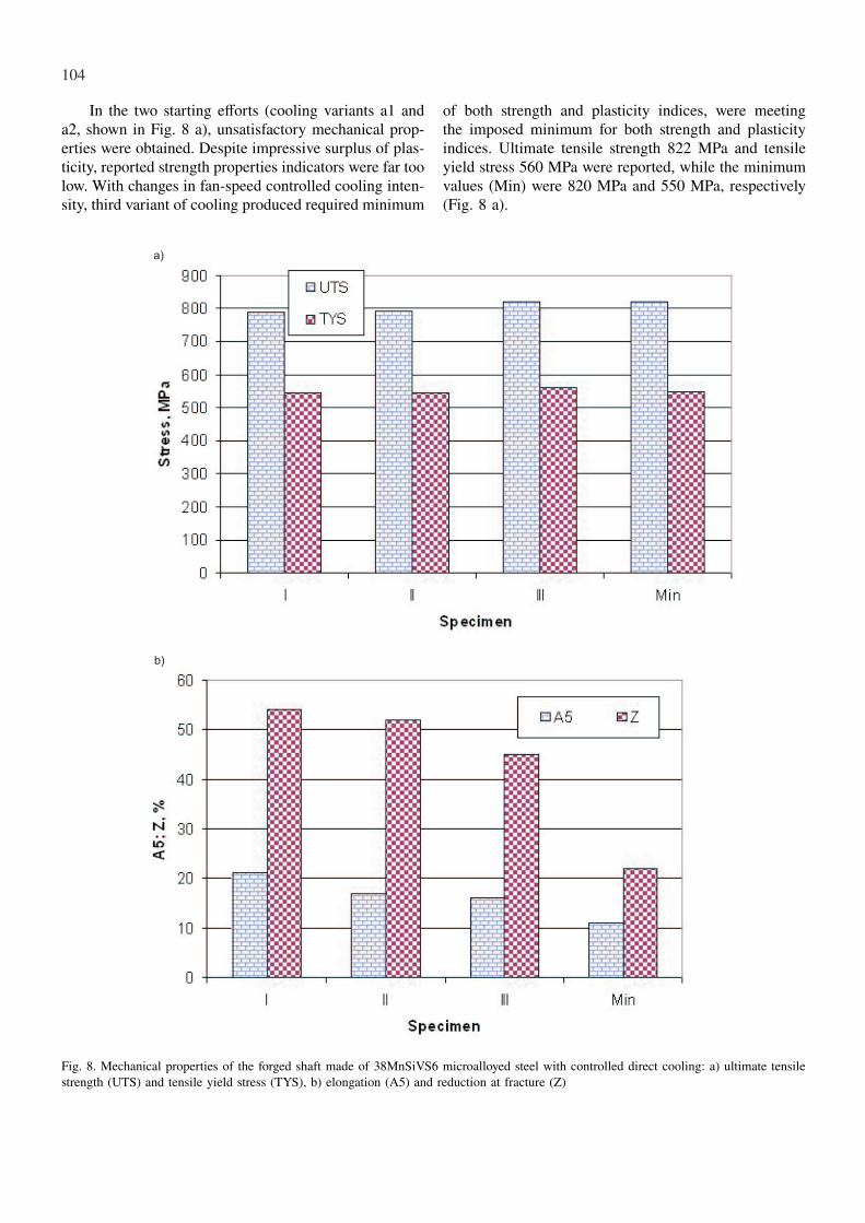
To verify the attitude of theoretical determination ofcooling conditions industrial trials were carried out. Theindustrial trials of controlled cooling was realized in aspecial tunnel-alike cooling line containing six coolingzones (S1÷S6), which made it possible for independentlycontrolled cooling intensity in each of them in order toobtain unique temperature regime in consecutive coolingstages. Temperature measurement was done with pyrom-eters mounted in each of the cooling station. In result ofinitial trials of eight computationally determined treat-ment cycles, three combinations of fan settings were se-lected, producing required course of temperature changesin consecutive zones (Fig. 7). For these variants speci-mens from the forgings were taken out and mechanicaltesting performed. The results of mechanical testing arepresented in figures 8 and 9.
Fig. 7. Temperature of the surface in consecutive zones: a1, a2, a3 – treatment cycles, O – start-of-cooling temperature, S1 ÷ S6 – coolingzones
104
In the two starting efforts (cooling variants a1 anda2, shown in Fig. 8 a), unsatisfactory mechanical prop-erties were obtained. Despite impressive surplus of plas-ticity, reported strength properties indicators were far toolow. With changes in fan-speed controlled cooling inten-sity, third variant of cooling produced required minimum
of both strength and plasticity indices, were meetingthe imposed minimum for both strength and plasticityindices. Ultimate tensile strength 822 MPa and tensileyield stress 560 MPa were reported, while the minimumvalues (Min) were 820 MPa and 550 MPa, respectively(Fig. 8 a).
a)
b)
Fig. 8. Mechanical properties of the forged shaft made of 38MnSiVS6 microalloyed steel with controlled direct cooling: a) ultimate tensilestrength (UTS) and tensile yield stress (TYS), b) elongation (A5) and reduction at fracture (Z)

105
Plasticity indices – area reduction at fracture andelongation at fracture for all of the variants were sig-nificantly higher than the required minimum. For thefirst and the second try it was threefold higher, reaching52÷54% (Fig. 8 b, a1 and a2). Next attempt broughtabout slight decrease in plasticity, nevertheless it stillformed a generous surplus over required level of 12% forelongation and 22% for reduction at fracture (Fig. 8 b,Min) reaching 16% and 24%, respectively (Fig. 8 b, a3).As such, it offers wide possibilities of further strengthimprovement for this chemistry.
Due to the tensile test specimen dimensions, tensiletesting resulted in a sort of an average through differ-ing in diameter sections of the forged part. As the ten-sile testing involved A5 specimens taken out from thecore zone of the forged part, the final strength proper-ties resulted from overall condition of the material inthe axis. To investigate how uniform the distribution ofmechanical properties really was, verifying numericallycalculated distribution of effective strain and tempera-ture, hardness measurements for selected locations in alengthwise cross-section were made. The measurementswere carried out for two parts, representing conventionalQ&T treatment and a3 cycle of TMT treatment, that is,
one with insufficient strength and the one that reachedrequired strength level. Measurements in five character-istic locations, designated in Fig. 9 with numbers from1 to 5, indicate several to a dozen percent discrepancies.As can be concluded from the maps of temperature pro-files in corresponding cross-sections (Fig. 5), those dif-ferences in hardness go along with cooling-rate relatedlocal temperature differences. For case “a” higher hard-ness in locations close to ends can be observed, whereasfor case “b” – in locations which represent the largestcross-sections.
Both strength properties and ductility are inextrica-bly related to obtained microstructure, therefore quanti-tative effects of controlled continuous cooling must beseen in grain size and morphology of structure compo-nents. Microstructure observed in the region of location1 is shown is shown in Fig. 10. Although differencesbetween particular cooling variants require more preciseanalysis, difference between grain structure after conven-tional Q&T (Fig. 10 a) and thermo-mechanical treatment(Fig. 10 b) are obvious. Both pearlite grains as well asferrite network developed in grain boundaries during di-rect cooling process are finely refined.
Fig. 9. Hardness measurement in locations 1÷5 in longitudinal cross-section of the crankshaft

106
Fig. 10. Microstructure of crankshaft produced in: a) forging and Q&T treatment, b) thermomechanical treatment with application of directcooling
5. Summary and conclusions
The results of presented study show large possibili-ties of control of final properties of forgings by means ofthermo-mechanical treatment in industrial practice. Keyissues in accomplishment of required level of final me-chanical properties of drop forgings are temperature anddeformation and their profiles at the end of forging oper-ation, as well as, subsequent cycle of direct cooling withappropriate cooling curves courses in particular. Both ofthem must fulfill unique requirements of precipitationkinetics for a given composition of steel.
Thermo-mechanical parameters of forging opera-tions, which are starting conditions for subsequent directcooling can be precisely determined with finite elementmethod modelling. As an output of the modelling the bil-let temperature, reduction, times and forging equipmentkinematics, which allow proper profiles of temperaturein forged part, are obtained. As far as cooling curvesare considered, to obtain their optimal course in everycross-section six cooling zones with independently con-trolled cooling rate were employed. Appropriate settingsensured required time-temperature regime during con-tinuous cooling directly after forging.
It can be concluded that air cooling with forcedair of about 20 m/s suffices to provide microstructureand mechanical properties typical of high-duty automo-tive forged parts. Despite differences in cooling curvesflow in the surface and the core of the shaft, as wellas those caused by varying cross-sectional dimensions,which brought about up to 18 HB hardness variation, itproduced UTS higher than 820 MPa and TYS 550 MPa.
Acknowledgements
Financial assistance of MNiSzW in the framework of17.17.110.963 agreement is acknowledged.
REFERENCES
[1] J. A d a m c z y k, Inżynieria wyrobów kutych ze stalikonstrukcyjnych mikrostopowych. Hutnik – WiadomościHutnicze. 11, 529-538 (1999).
[2] A.B. C o t a, F.E.G. O l i v e i r a, A.L. B a r b o s a[et al.], Microstructure and Mechanical Properties of aMicroalloyed Steel After Thermal Treatments. MaterialsResearch 6, 2, 116-121 (2003).
[3] K.W. W e g n e r, Werkstoffentwicklung fur Schmiede-teile im Automobilbau. ATZ AutomobiltechnischeZeitschrift 100, 12, 918-927 (1998).
[4] J. K n e l l e r [et al.], Steel’s Technical and Econom-ical Progress in the Production of Lighter and SmallerEngine Components. American Iron and Steel Institute,25 (2003).
[5] V. O l l i l a i n e n, W. K a s p r z a k, L. H o l a p p a,The effect of silicon, vanadium and nitrogen on the mi-crostructure and hardness of air cooled medium carbonlow alloy steels. Journal of Materials Processing Tech-nology, 134, 405-412 (2003).
[6] D.K. M a t l o c k, G. K r a u s s, J.G. S p e e r, Mi-crostructure and properties of direct-cooled microalloyforming steels. Journal of Materials Processing Technol-ogy 117, 324-328 (2001).
[7] A. N i e c h a j o w i c z, A. T o b o t a, Warm deforma-tion of carbon steel. Journal of Materials ProcessingTechnology 106, 123-130 (2000).
[8] M. J a h a z i, B. E g h b a l i, The influence of hotforging conditions on the microstructure and mechan-ical properties of two microalloyed steels. Journal ofMaterials Processing Technology 113, 594-598 (2001).
[9] J. S i ń c z a k, A. Ł u k a s z e k - S o ł e k, P. S k u -b i s z, S. B e d n a r e k, Kucie matrycowe odkuwkikołnierza z zastosowaniem obróbki cieplnoplastycznej.Hutnik – Wiadomości Hutnicze 3, 187-191 (2007).
[10] B.K. P a n i g r a h i, Bull. Mater. Sci. 24, 4, 361-371August 2001.
[11] T. G l a d m a n, The Physical Metallurgy of Microal-loyed Steels, The Institute of Materials, 1997.

107
[12] H. A d r i a n, Materials Science and Technology 8,406-420 (1992).
[13] H. A d r i a n, Proceedings of the International Confer-ence ”Microalloying’95”, ed. by M. Korchynsky, A.J.DeArdo, P. Repas i G. Tither, Pittsburgh, 285-307(1995).
[14] H. A d r i a n, Thermodynamic model for precipitationof carbonitrides in HSLA steels with an application tohardenability investigations, Ed. AGH, Kraków, 1995 (inPolish).
[15] P. G r i e v e s o n, Proc.Brit.Ceram. Soc. 8, 137 (1967).[16] C. W a g n e r, Thermodynamics of alloys, 1952, Read-
ing, MA Addison-Wesley.
[17] K. N a r i t a, Physical Chemistry of the Groups IVa(Ti,Zt), Va (V,Nb,Ta), Trans ISIJ 15, 145-152 (1975).
[18] K. C h a k r a b o r t y, A.B. C h a t t o p a d h y a y,A.K. C h a k r a b a r t i, A study on the grindability ofniobum microalloyed forging quality HSLA steels. Jour-nal of Materials Processing Technology 141, 404-410(2003).
[19] R. K u z i a k, T. B o l d, Y.W. C h e n g, Mictrostruc-ture Control of Ferrite-Pearlite High Strength Low Al-loy Steel Microalloy Additions. Journal of MaterialsProcessing Technology 53, 255-262 (1995).
Received: 20 August 2010.