controller access technical bulletin · 2015-06-05 · 6 controller access technical bulletin...
TRANSCRIPT

Technical BulletinIssue Date August 6, 2002
© 2002 Johnson Controls, Inc. www.johnsoncontrols.comCode No. LIT-6364013
Controller Access
Controller Access..................................................................................2
Introduction......................................................................................................... 2
Key Concepts...................................................................................................... 3
Direct Access .................................................................................................................... 3
RS-232 Application (DX Only)........................................................................................... 6
Auxiliary Access ................................................................................................................ 6
Connection Monitoring ...................................................................................................... 7
Stand-Alone NDM with a Passive Printer.......................................................................... 8
Stand-Alone NDM ............................................................................................................. 9
Companion/Facilitator System ........................................................................................ 10
Cable Connection............................................................................................................ 11
OWS Access ................................................................................................................... 11
Procedure Overview......................................................................................... 13
Detailed Procedures......................................................................................... 14
Connecting to a Remote NDM ........................................................................................ 14
Connecting to a Companion/Facilitator System with a Cable ......................................... 15
Connecting to a Remote NDM or Companion Site Using Auxiliary Accesswith a Modem.................................................................................................................. 17
Connecting to a Companion Site Using Auxiliary Access with a Cable .......................... 20
Disconnecting from a Site ............................................................................................... 20
Troubleshooting ............................................................................................... 21
Troubleshooting Chart..................................................................................................... 21

Controller Access Technical Bulletin2
Controller Access
IntroductionThis document describes the methods available to communicate to ourcurrent controller product line. You can communicate using directaccess, auxiliary access, or Operator Workstation (OWS) access.
Direct access allows software Configuration Tools to directlycommunicate with most controllers. Specific interface hardwaredevices convert PC RS-232 signals to either N2 (RS-485) or Zone Bussignal levels. N2 only converter devices are the MM-CVT101 andAS-TBL485. A Zone Bus only converter is the AS-CBLPRO-x. TheAS-CVTPRO connects to either the N2 Bus or Zone Bus.
The Auxiliary Access feature allows the user to access many of thecontrollers connected to a Metasys Companion orFacilitator™ system (Personal Computer [PC] or Panel) or a remoteN2 Bus monitored by a remote N2 Dialer Module (NDM). AuxiliaryAccess requires a modem or cable connection.
OWS access provides accessibility to devices connected to aMetasys Network Control Module (NCM).
Refer to the M-Tool Overview and Installation Technical Bulletin(LIT-693100) for more pass through information.

Controller Access Technical Bulletin 3
Key Concepts
Direct AccessDirect access allows Configuration Tools to connect to mostcontrollers on the N2 Bus using an MM-CVT101 or AS-TBL485.Connect to the Zone Bus using an AS-CBLPRO-x. Connect to eitherthe N2 Bus or Zone Bus using an AS-CVTPRO. The user can thenupload, download, and commission Application Specific Controllers(ASCs) [Variable Air Volume (VAV), Unitary (UNT), Air HandlingUnits (AHUs)], TC-9102 controllers, Variable Air Volume ModularAssembly (VMA) devices, and DX-9100 controllers.
N2 Bus Application (MM-CVT101 or AS-TBL485)Connect the PC to the controller N2 Bus, an MM-CVT101*, or anAS-TBL485. Configuration tool software communicates to a singlecontroller at one time or the software can scan the entire N2 Bus forlimited controller information.
* Windows 2000 and Windows NT operating systems do notwork with an MMCVT101.
You can also communicate directly to DX controllers by connectingthe PC’s RS-232 port to the DX controller’s RS-232 port with a nullmodem cable. (DX is the only controller with a built-in RS-232 port.In this case, do not use the converter. Only one master is allowed onthe N2 Bus at a time.)
IMPORTANT: You must disconnect the N2 Bus from thesupervisory system before connecting the CVT101 or AS-TBL485 to theN2 Bus.
Local2
9- or 25-pinRS-232 serial port
VAVController
UNTController
AHUController
N2 Bus
DX-9100Controller
TC-9102Controller
25-pin
Use 9-pin to 25-pinadapter if needed.
VMADevice
Figure 1: Direct Access Example (N2 Bus Application)
Note: For more information, see HVAC PRO User’s Manual.
Controller Access Technical Bulletin4
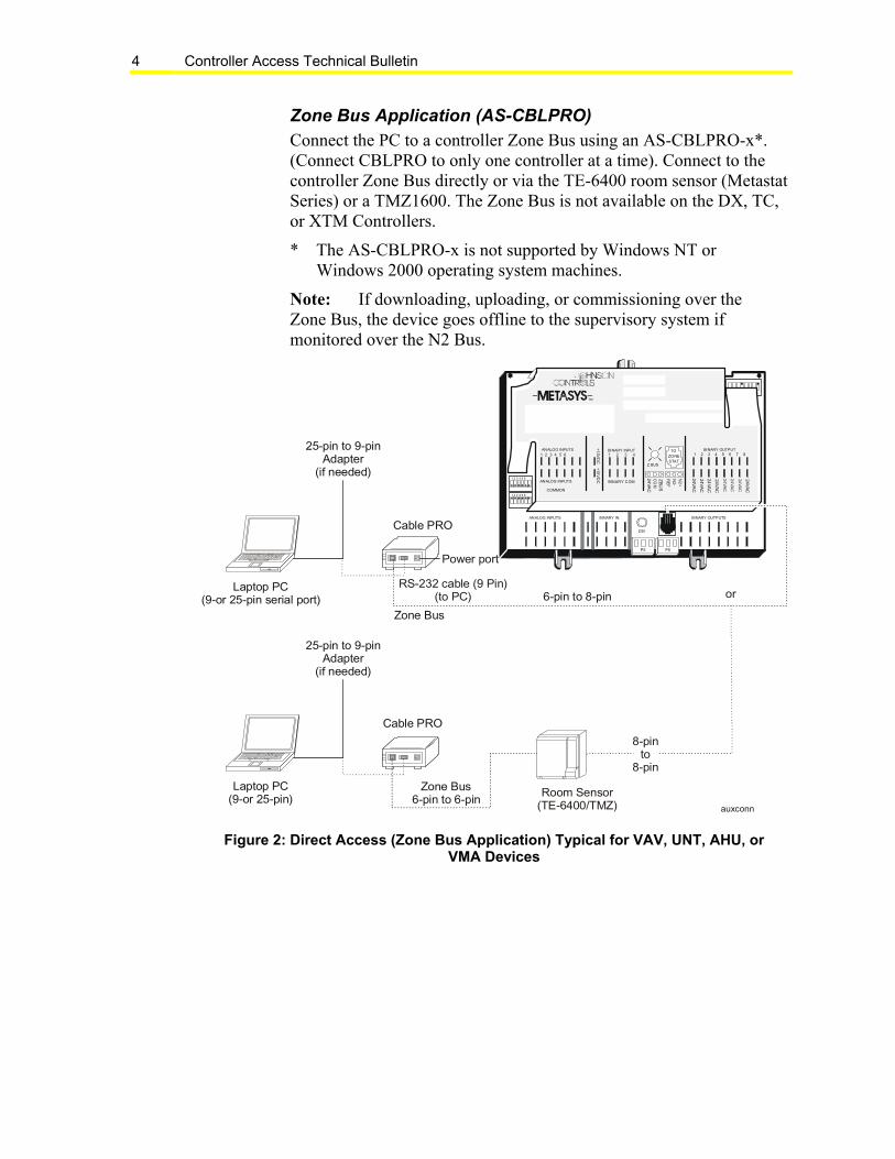
Zone Bus Application (AS-CBLPRO)Connect the PC to a controller Zone Bus using an AS-CBLPRO-x*.(Connect CBLPRO to only one controller at a time). Connect to thecontroller Zone Bus directly or via the TE-6400 room sensor (MetastatSeries) or a TMZ1600. The Zone Bus is not available on the DX, TC,or XTM Controllers.
* The AS-CBLPRO-x is not supported by Windows NT orWindows 2000 operating system machines.
Note: If downloading, uploading, or commissioning over theZone Bus, the device goes offline to the supervisory system ifmonitored over the N2 Bus.
Cable PRO
Laptop PC(9-or 25-pin)
25-pin to 9-pinAdapter
(if needed)
1 2 3 4 5 6 7 8
1 2 3 4 5 6
BINARY INANALOG INPUTS BINARY OUTPUTS
TM
BINARY INPUTANALOG INPUTS1 2 3 4 5 6 1 2 3 4
ANALOG INPUTS
COMMON
+1
5VD
C
TOZONESTAT
BINARY OUTPUT
24VA
C
1 2 3 4 5 6 7 8
+15
VD
C 24VA
C
RE
F
N2-
N2
+
24VA
CC
OM
ZB
US
Z BUS
DSI
P5 P6
1 2 3 4 5 6 24VA
C
24VA
C
24
VA
C
24
VA
C
24V
AC
24VA
C
BINARY COM
Cable PRO
Laptop PC(9-or 25-pin serial port)
Zone Bus6-pin to 6-pin
25-pin to 9-pinAdapter
(if needed)
auxconn
Zone Bus
6-pin to 8-pin
Room Sensor(TE-6400/TMZ)
Power port
RS-232 cable (9 Pin)(to PC)
8-pinto
8-pin
or
Figure 2: Direct Access (Zone Bus Application) Typical for VAV, UNT, AHU, orVMA Devices

Controller Access Technical Bulletin 5
N2 Bus or Zone Bus (MM-CVTPRO)Note: Do not connect the CVTPRO to both the N2 Bus and ZoneBus at the same time.
The CVTPRO connects to controllers via the N2 Bus or the Zone Bus(Figure 3). The CVTPRO supports multiple operating systems andoffers compatibility with Palm™ Personal Digital Assistants (PDAs).Refer to the Auxiliary Gear Technical Bulletin (LIT-6363080) formore information on CVTPRO connections and operating systemcompatibility.
Personal Computer (1)or
DB9 Port
TE-6x00/TMZ Room Sensor
RJ11 Jack,6-Pin
CompatibleController
Zone Bus RJ45 Jack,8 Pin
Zone Bus/N2 Bus
RJ11 Jack6-pin
F
IND
CA
LC ULATO
R
M
E NU
a b c d e 1 2
3 4 5
A
PP
LI
C AT
ION
S
Palm III, Palm VII device (1,2)
Palm V with Dock V PRO Adapter, or
Cvtschematic
External Power (3)
N2 BusN2 Bus Interface,4-Pin N2 Socket/
3-Pin N2 Plug with Tab
CVTPRO
Serial Port or
or
F
IND
CALCULATO
R
M
E N U
a b c d e 1 2 3
4 5
APP
LI
C AT
I ON
S
Palm m1xx or m5xx (with additional connectors)
DB9 Connector
Notes:1. Do not connect the CVTPRO to the Palm device and laptop/PC at the same time. 2. Unplug the Palm device from the CVTPRO when not in use (conserves battery power).3. The CVTPRO200-0 (European version) does not ship with an external power adapter.
Figure 3: CVTPRO Connections

Controller Access Technical Bulletin6
RS-232 Application (DX Only)Connect the PC to the DX serial port connection located on the DXbase with a null modem cable or a standard RS-232 cable (9-pin atDX) and a null modem adapter. This connection allowscommunication to a single DX-91x0 to perform download/upload(using the GX-9100) and commissioning of the DX and extensionmodules. The controller does not go offline if connected to the N2.
Rs232
PC
Null ModemAdaptor
RS-232
DX-91x0Controller
B/S
Figure 4: Direct Access (RS-232 Application)
Auxiliary AccessThe Auxiliary Access feature in the Configuration Tools programgroup allows the user to access controllers connected to aCompanion/Facilitator system or a remote N2 Bus being monitored bya remote NDM.
Auxiliary Access provides two methods of accessing these remotecontrollers:
• modem connection - the user dials out to remote controllersthrough a remote NDM or Companion/Facilitator system(Release 6.00 or later).
• cable connection - the user directly connects a PC to a remoteNDM or Companion/Facilitator system (Release 6.00 or later)without disconnecting the N2 Bus from the monitoring system atthe remote site.
Use either the modem or cable connection feature to upload,download, and commission controllers through the N2 Bus, with aCompanion/Facilitator system or NDM. For a Companion/Facilitatorsystem, the controller must be mapped into the Companion/Facilitatordatabase for this feature to work.
Note: The NDM and the Companion/Facilitator system do notsupport the VMA; therefore, Auxiliary Access does not support theVMA.
Controller Access Technical Bulletin 7
Modem ConnectionThe modem connection feature allows the user to dial out to remotecontrollers in three ways:
• to a stand-alone NDM with a passive printer
• to a stand-alone NDM
• to a remote Companion/Facilitator system
Modem connection requires a Hayes® compatible 9600 baud modemat the Configuration Tools PC and at the remote site.
Connection MonitoringDuring a valid remote connection, Auxiliary Access monitors theconnection periodically. If communications are interrupted, a dialogbox appears stating you must reconnect. The Auxiliary Access iconthen changes to the inactive state. To reconnect, see the Connecting toa Remote NDM or Companion Site Using Auxiliary Access with aModem section of this document.
Note: The Companion/Facilitator system disconnects AuxiliaryAccess after 60 seconds without communications.

Controller Access Technical Bulletin8
Stand-Alone NDM with a Passive PrinterIn a local passive printer application, a remote NDM initiates a call toa local printer to pass alarm information to the local site. To clear thesealarm conditions, use the modem connection feature to dial the remotesite to commission the controller in alarm. For more information, seethe N2 Dialer Module (NDM) Technical Bulletin (LIT-6363065).
TC9102
Power
R/ T
METAS YS
Local Modem
PC RunningAuxiliary Access
Remprint
Local Modem
Local Printer(Stand-alone)
Local Site
Remote Site
N2 Bus
Remote Modem VAVController
UNTController
AHUController
DX-9100Controller
TC-9102Controller
Figure 5: Using Auxiliary Access to Clear Alarms in a Passive PrinterApplication

Controller Access Technical Bulletin 9
Stand-Alone NDMAuxiliary access can dial a stand-alone remote network. In thisapplication, the NDM provides the modem connection to the network.
TC9102
Power
R/ T
METAS YS
Local Modem
PC RunningAuxiliary Access
Remprt2
N2 Bus
Remote Modem VAVController
UNTController
AHUController
DX-9100Controller
TC-9102Controller
Figure 6: Stand-Alone Remote Network

Controller Access Technical Bulletin10
Companion/Facilitator SystemIn the pass-through mode available with Companion/FacilitatorRelease 6.00 or later, use Configuration Tools software to directlyaccess controllers on the N2 Bus through a Companion system.Auxiliary access provides the connection link that utilizes thepass-through mode. With the modem connection feature, you initiate acall to the Companion system through a 9600 baud modem.
At the remote site, if you are using a Panel versionCompanion/Facilitator system with a PC running VT100 emulationsoftware, exit the emulation software, run Auxiliary Access software,and the cable connections do not change. After establishing connectionand passing verification codes between the Companion/Facilitatorsystem and Auxiliary Access which runs on the Configuration ToolsPC, the Companion/Facilitator system enters the pass-through mode.At this point, you can upload, download, or commission individualcontrollers on the N2 Bus using Configuration Tools software; thecontroller maintains full functionality. You must map the controllerinto the Companion/Facilitator database for this feature to work.
While in or out of the pass-through mode, the Companion/Facilitatorsystem maintains full network operations and communications,including keeping the controllers online. During Auxiliary Access, if acontroller resets, it goes offline to the Companion/Facilitator system.
Notes: Companion/Facilitator Release 6.02 or later must be able todownload an XT-9100 Extension Module connected toDX-9100 controllers through Companion/Facilitator system.
When using this feature on a Companion/Facilitator system,the supervisory system remains in control. Although thecontroller you are commissioning may be offline to thesupervisory system, the rest of the network is still processingcommands from the supervisory system. If you need theCompanion/Facilitator system to reissue manual or operatoroverride commands after commissioning, you must reset thecontroller.

Controller Access Technical Bulletin 11
PC RunningAuxiliary Access
BuildingAutomation
System
N2 Converter
or
PC Version
N2 Bus
VAVController
UNTController
AHUController
DX-9100Controller
TC-9102Controller
remprt3
Panel Version
Figure 7: Pass-Through Mode for a Companion/Facilitator PC or PanelConfiguration
Cable ConnectionThe cable connection feature is used to directly connect to thecommunications port of either a Companion/Facilitator system orNDM without having to disconnect the N2 Bus from the monitoringsystem at the remote site. You can upload, download, and commissionthe controllers through the monitoring system.
Note: Remote alarms, which have triggered a dial in a passiveapplication, cannot be cleared using this cable connection feature. Youmust dial using the modem connection feature of Auxiliary Access toclear alarms and enable the NDM to dial for subsequent alarms in thecontroller that caused the alarm.
OWS AccessNote: You must have Metasys Release 6.00 or later to runConfiguration Tools from the OWS. Metasys Release 9.00 or later isrequired to support object mapping to VMA devices.

Controller Access Technical Bulletin12
The Configuration Tools that support access to remote controllersfrom the Metasys OWS are HVAC PRO software,DX Commissioning, and NDM Configurator. You can access thesetools through the custom application menu or through ProgramManager. Metasys Release 7.01 or later includes System 91 supportfor DX Commissioning and TC-9102 controllers.
owsn2
OperatorWorkstation
N1 Local Area Network (LAN)
Network Control
Unit (NCU)
N2 Bus
VAVController
UNTController
AHUController
N2 Bus
DX-9100Controller
TC-9102Controller
VMADevice
Figure 8: OWS Access
Note: The Auxiliary Access feature is not functional while runningConfiguration Tools on the Metasys OWS.
For more information, see the HVAC PRO User’s Manual.

Controller Access Technical Bulletin 13
Procedure OverviewTable 1: Controller Access
To Do This Follow These Steps:Connect a Remote NDM. Turn off the modem. Disconnect the cable
from the modem. Connect your laptopcomputer to the cable on the NDM using a nullmodem cable. Use Configuration Tools tocommunicate with the remote controllersthrough the NDM. When finished, reconnectthe modem cable to the modem. Turn on themodem.
Connect aCompanion/Facilitator Systemwith a Cable.
Connect your laptop computer to theCompanion/Facilitator system using a nullmodem cable. Use Configuration Tools tocommunicate with the remote controllersthrough the Companion/Facilitator system.
Connect to a Remote NDM orCompanion Site UsingAuxiliary Access with aModem.
On the Windows Start menu selectPrograms > Configuration Tools > AuxiliaryAccess. Select the PC Port. Select Modem inthe Connection Type box. Enter the PhoneNumber. Click OK to confirm the modem setupstrings and to return to the Auxiliary Accessdialog box. Select the Connect Button toinitiate or restart the dial sequence.
Connect to aCompanion/Facilitator SiteUsing Auxiliary Access with aCable.
On the Windows Start menu selectPrograms > Configuration Tools > AuxiliaryAccess. Select the Port. Select Cable in theConnection Type box. Select the Connectbutton to establish the connection.
Disconnect from a Site. Single-click on the active Auxiliary Accesstaskbar to display the System menu. SelectDisconnect Site. Select Close. Select Yes toterminate the connection.
Controller Access Technical Bulletin14
Detailed Procedures
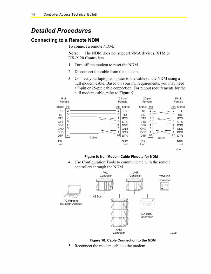
Connecting to a Remote NDMTo connect a remote NDM:
Note: The NDM does not support VMA devices, XTM orDX-9120 Controllers.
1. Turn off the modem to reset the NDM.
2. Disconnect the cable from the modem.
3. Connect your laptop computer to the cable on the NDM using anull modem cable. Based on your PC requirements, you may needa 9-pin or 25-pin cable connection. For pinout requirements for thenull modem cable, refer to Figure 9.
ndmend
Pin Signal
25-pinFemale
TDRDRTSCTSDSRGNDDCDDTR
RDTD
RTSCTSDSRGNDDCDDTR
Signal Pin
Cable
9-pinFemale
PCEnd
NDMEnd
Signal Pin
Cable
25-pinFemale
PCEnd
Pin Signal
25-pinFemale
TDRDRTSCTSDSRGNDDCDDTR
NDMEnd
TD
RDRTSCTSDSRGNDDCDDTR
23786514
234567820
234567820
234567820
Figure 9: Null Modem Cable Pinouts for NDM
4. Use Configuration Tools to communicate with the remotecontrollers through the NDM.
cable2
PC Running(Auxiliary Access)
TC9102
Power
R / T
M E T A S Y S
VAVController
UNTController
AHUController
N2 Bus
DX-9100Controller
TC-9102
Controller
Figure 10: Cable Connection to the NDM
5. Reconnect the modem cable to the modem.
Controller Access Technical Bulletin 15
6. Turn on the modem. If you configure the NDM with a local phonenumber, it dials the local site and report its online status as well asthe online status of the other controllers on the N2 Bus.
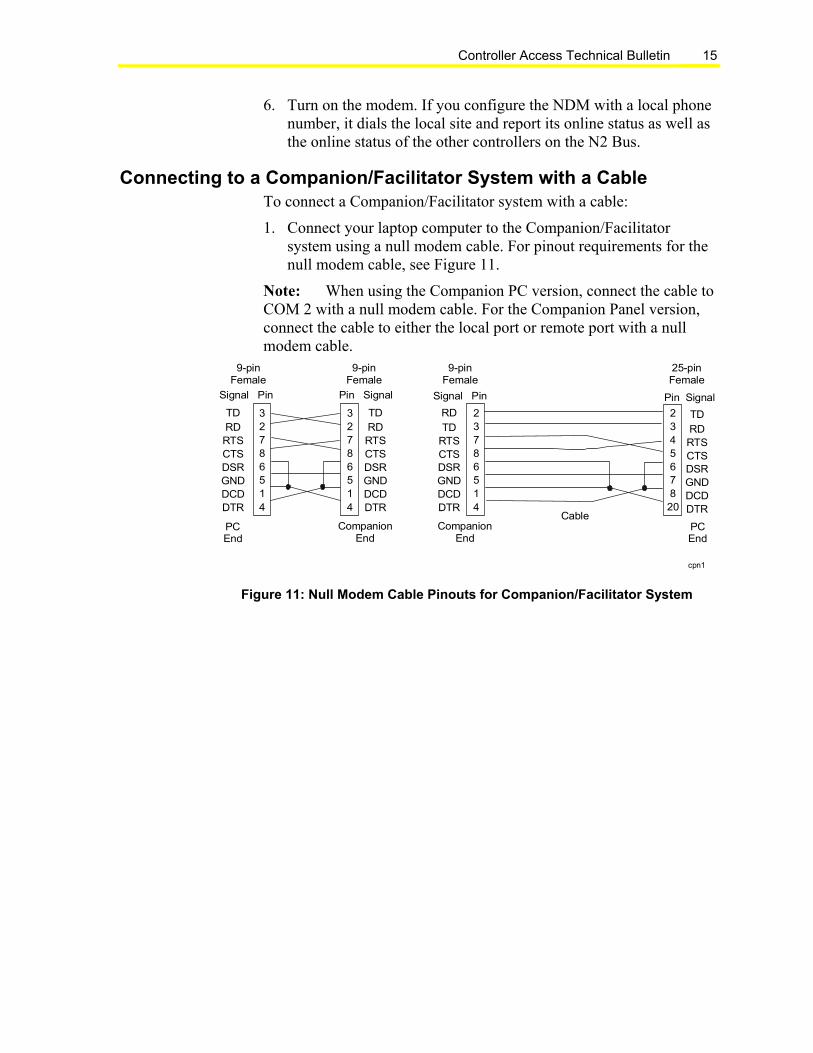
Connecting to a Companion/Facilitator System with a CableTo connect a Companion/Facilitator system with a cable:
1. Connect your laptop computer to the Companion/Facilitatorsystem using a null modem cable. For pinout requirements for thenull modem cable, see Figure 11.
Note: When using the Companion PC version, connect the cable toCOM 2 with a null modem cable. For the Companion Panel version,connect the cable to either the local port or remote port with a nullmodem cable.
234567820
23786514
32786514
cpn1
Pin Signal
TDRDRTSCTSDSRGNDDCDDTR
TDRDRTSCTSDSRGNDDCDDTR
Signal Pin
CompanionEnd
Pin Signal
TD
RDRTSCTSDSRGNDDCDDTR
RD
TDRTSCTSDSRGNDDCDDTR
Signal Pin
Cable
9-pinFemale
PCEnd
PCEnd
CompanionEnd
32786514
9-pinFemale
9-pinFemale
25-pinFemale
Figure 11: Null Modem Cable Pinouts for Companion/Facilitator System

Controller Access Technical Bulletin16
Converter(MM-CVT101-0)
cable1
or
Panel Version
PC Version
PC RunningAuxiliary Access
N2 Bus
VAVController
UNTController
AHUController
DX-9100Controller
TC-9102Controller
Building Automation
System
Null ModemCable
Null ModemCable
Figure 12: Cable Connection to Companion
2. Use Configuration Tools to communicate with the remotecontrollers through the Companion/Facilitator system.

Controller Access Technical Bulletin 17
Connecting to a Remote NDM or Companion Site Using AuxiliaryAccess with a Modem
To connect to a remote NDM or a Companion site using AuxiliaryAccess with a modem:
1. On the Windows Start menu select Programs > ConfigurationTools > Auxiliary Access. The Auxiliary Access dialog boxappears (Figure 13).
Figure 13: Auxiliary Access Dialog Box
Note: When you select Cable for the Connection Type, the PhoneNumber field and Modem Setup button are not used and, therefore,appear dimmed.
2. Select the PC Port.
3. Select Modem in the Connection Type box.
4. Enter the Phone Number. The previous, successful number isdisplayed as the default.
Note: If a modem other than a Hayes compatible application isused, the modem setup may need to change. If the setup is new or hasbeen modified, select the Modem Setup button to enter specificmodem initialization character strings. The Connect Remote Site -Modem Setup dialog box appears (Figure 14).

Controller Access Technical Bulletin18
Note: Default modem setup strings are provided for a standardHayes compatible modem. Refer to the Metasys Modems 2ResourcePage for details. The telephone number, port selections, connectiontimeout value, and modem setup strings are preserved as defaults forany subsequent dial commands. There is room for seven setup strings,a dialing prefix, and a connection timeout.
Figure 14: Default Modem Setup Strings
5. Figure 14 shows the default modem setup strings, which are sent tothe modem in the auxiliary dial application.
Controller Access Technical Bulletin 19
Table 2: Default Modem Setup Strings
String Description&F Recall factory settings.
E0 Disable character echo.
*L0 Low speaker volume.
N0 Lock in at speed specified in S37.
Q1 Disable result codes.
&C1 DCD tracks the carrier.
&D3 DTR signals a hard-reset of modem.
&S0 DSR is always active.
*S0 = 1 Answer after one ring.
*S8 = 4 Comma duration set at 4 seconds.
*S11 = 50 Used to increase dialing speed (tone only).
S37 = 9 Connect only at 9600 baud.
&Q0 = Force asynchronous communications.
* Only these parameters may be changed from default values. All other listedparameters require default values for proper connection.
6. Click OK to confirm the modem setup strings and to return to theAuxiliary Access dialog box.
7. Select the Connect button to initiate or restart the dial sequence, orselect the Cancel button to exit. Only one telephone number is inthe Auxiliary Access initialization file. If problems arise whilemaking a remote connection, an error message appears.
Notes: All Configuration Tools must use the same port used in theAuxiliary Access application.
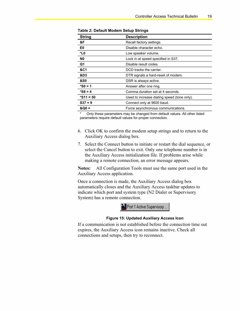
Once a connection is made, the Auxiliary Access dialog boxautomatically closes and the Auxiliary Access taskbar updates toindicate which port and system type (N2 Dialer or SupervisorySystem) has a remote connection.
Figure 15: Updated Auxiliary Access Icon
If a communication is not established before the connection time outexpires, the Auxiliary Access icon remains inactive. Check allconnections and setups, then try to reconnect.

Controller Access Technical Bulletin20
Connecting to a Companion Site Using Auxiliary Access witha Cable
To connect to a Companion site using Auxiliary Access with a cable:
1. On the Windows Start menu select Programs > ConfigurationTools > Auxiliary Access. The Auxiliary Access dialog boxappears (Figure 13).
2. Select the Port.
3. Select Cable in the Connection Type box. The Phone Number fieldand Modem Setup button are not required and appear dimmedwhen using the cable connection.
4. Select the Connect button to establish the connection, or select theCancel button to exit.
Note: Once a connection is made, the Auxiliary Access dialog boxautomatically closes and the Auxiliary Access taskbar updates toindicate the selected port (Figure 15) and supervisory system.
Disconnecting from a SiteThe disconnect can be initiated either manually or from fault detection.
1. Single-click on the active Auxiliary Access taskbar to display theSystem menu (Figure 16).
Figure 16: System Menu
2. Select Disconnect Site.
3. Select Close. This completes the disconnect and terminates theAuxiliary Access icon. A Disconnect Site Verification dialog boxappears.
4. Select Yes to terminate the connection. The termination interruptsany communication in progress. The Auxiliary Access iconchanges to the disconnected state on the screen and remains untilspecifically closed through the System menu.

Controller Access Technical Bulletin 21
Troubleshooting
Troubleshooting Chart
Table 3: Troubleshooting
Symptom Possible Cause ActionIncorrect modemconfiguration
Verify Auxiliary Access and NDMconfigurations for recommendedHayes Advanced Technology(AT) command strings
Cable between modem andNDM is not connected.
Verify cable connection betweenmodem and NDM.
No communication to remote NDM, eventhough Port (n) Active N2 Dialerindicates connection to NDM
NDM is turned off. Verify that NDM is turned on.
Verify Auxiliary Accessconfigurations to recommendedHayes AT command string.
Incorrect modemconfiguration
Verify supervisory systemmodem setup with Modem PROfor recommended local HayesAT command strings.
No cable connection and/orincorrect cableconfiguration betweenmodem and supervisorysystem.
Verify cable connection andconfiguration between modemand supervisory system.
Incorrect null modem cable Verify that the correct nullmodem cable is used as shownin Figure 9.
No communication to supervisorysystem. Port (n) Active N2 Dialer isindicated instead of Port (n) ActiveSupervisory System.
Note: If communication handshake tothe supervisory system (modem orcable connection) is incorrect, theport connection message defaultsto Port (n) Active N2 Dialer.
Remote supervisorysystem is turned off.
Verify that remote supervisorysystem is turned on.
ASC devices are offline tothe supervisory system.
Use VT-100 emulation to verifythat all ASC devices are online tothe supervisory system.
ASC hardware devices arenot mapped in thesupervisory system.
Use VT-100 emulation to verifythat all ASC hardware devicesare mapped in the supervisorysystem.
No communication to ASC devices,even though Port (n) Active SupervisorySystem indicates connection tosupervisory system.
N2 Bus problems See the ASC and N2 BusNetworking and TroubleshootingGuide (LIT-6363003) to verifyand resolve N2 Bus problem.
Controls Group507 E. Michigan StreetP.O. Box 423 www.johnsoncontrols.comMilwaukee, WI 53201 Printed in U.S.A.