controller - plcproducts.com · controller installation & programming 5 4 32 1 +-shld 1 2 34 5...
TRANSCRIPT

Controller Installation & Programming
54
32
1
+-
SHLD
12
34
5
UNIVERSALINPUTS
INFINET PORT
24VAC0.17A, 4VA 50/60HZ
L
IN1IN2
IN3IN4 RET

Andover Controls Corporation
2002, Andover Controls Corporation All Rights Reserved No part of this publication may be reproduced, read or stored in a retrieval system, or transmitted, in any form or by any means, electronic, mechanical, photocopying, recording, or otherwise, without prior written permission of Andover Controls Corporation. Produced in the United States of America. Infinity, Continuum and CyberStation are trademarks of Andover Controls Corporation. All other trademarks are the property of their respective owners. i2867 Installation & Programming Guide , Version: B February, 2002 Andover Controls part number: 30-3001-796 The information in this book is furnished for informational purposes only, is subject to change without notice, and should not be construed as a commitment by Andover Controls Corporation. Andover Controls Corporation, assumes no liability for any errors or inaccuracies that may appear in this document.
Andover Controls Corporation 300 Brickstone Square Andover, MA 01810 (978) 470-0555 fax: (978) 470-0946

i2867 Installation & Programming Guide
Radio Interference This equipment has been tested and found to comply with the limits for a Class A digital device,
pursuant to Part 15 of the FCC Rules. These limits are designed to provide reasonable protection
against harmful interference when the equipment is operated in a commercial environment. This
equipment generates, uses, and can radiate radio frequency energy and, if not installed and used in
accordance with the instructions in this manual, may cause harmful interference to radio
communications. Operation of this equipment in a residential area is likely to cause harmful
interference in which case the user will be required to correct the interference at his own expense.
Note This digital apparatus does not exceed the Class A limits for radio noise emissions from digital
apparatus set out in the Radio Interference Regulations of the Canadian Department of
Communications.
Avis Le présent appareil numérique n’émet pas de bruits radioélectriques dépassant les limites
applicables aux appareils numériques de la class A prescrites dans le Règlement sur le brouillage
radioélectrique édicté par le ministère des Communications du Canada.

Andover Controls Corporation

i2867 Installation & Programming Guide
Contents
Introduction...................................................................... 1
i2867 Module Characteristics ......................................... 2
Mechanical Installation.................................................... 3
Power Connection ........................................................... 6 Battery Connection & Replacement...........................................6 24VAC Connection .....................................................................8 Building Ground Requirements ...............................................10
Infinet Network Connection .......................................... 11
Input Connections ......................................................... 12 Universal Inputs........................................................................12 Input Wiring ..............................................................................12 Wiring Concerns.......................................................................13 Input Pull-up Resistor Selection ..............................................13 Measuring Temperature ...........................................................15 Measuring DC Voltages............................................................18 Sensing Contact Closures .......................................................19 Counting Pulsing Signals or Contact Closures ......................20
Output Connections ...................................................... 21 Digital Outputs (Form A) ..........................................................23 Tri-state Output.........................................................................24 Combining Form A Outputs as a Tri-state Output ..................24 Analog Voltage Output .............................................................25 Smart Sensor Interface.............................................................26
Programming ................................................................. 27 Configuration............................................................................27 Operation After Power Loss.....................................................27 I/O Point Assignments..............................................................39 Pre-Operation Checks ..............................................................40
Troubleshooting............................................................. 41

Andover Controls Corporation

i2867 Installation & Programming Guide 1
TCX 865
This manual describes the installation, and use of the i2867 Terminal Control Unit. This compact terminal control unit provides low-cost DDC control of package units, VAV boxes, unit ventilators, and other terminal unit applications with its versatile mix of inputs, outputs, plus an interface to Andover Controls' Smart Sensor Bus. The i2867 features combinations of universal inputs, Analog, Form A, and Tri-state outputs for flexible control configurations. The Infinet’s true peer-to-peer communications protocol provides the Infinity i2867 with the ability to instantly communicate with an Infinity network controller such as the Continuum NetController, as well as the entire network of Andover Infinet field controllers. Up to 254 i2867 controllers can be networked to one network controller.
54
32
1
+-
SHLD
12
34
5
UNIVERSALINPUTS
INFINET PORT
24VAC0.17A, 4VA 50/60HZ
L
IN1IN2
IN3IN4 RET

2 Andover Controls Corporation
i2867 Module Characteristics
The following lists the features included in the i2867 Controller Module:
• 4 Universal Inputs
• 1 Temperature Input/ Smart Sensor Bus Interface
• 5 Form A Triac Outputs
• 2 Analog Outputs (0-10V)
• 24VAC input power
• Infinet Interface
If You Are Upgrading From the TCX 867 The i2867 includes many advantages over the TCX867 and a few differences. The Triac output section of the i2867 is designed to provide low side switching. Before replacing a TCX867 with this product make sure that your outputs are wired as shown on page 23 of this manual.
If you are interfacing a Sensor Plus peripheral to the i2867, follow the directions given in the Sensor Plus documentation (version C or higher) to detect the activation of the override button. Do not use the procedure recommended for use with the TCX867.
Controller Limitations Using SX8000 Based Systems Plain English Programs Creating a program in the i2867 using the terminal interface that sets the digitalfilter attribute of a voltage input will save successfully into the SX database, however, it cannot be edited and saved. This is because the TCX867 Infinet I controller did not include the ability to use this attribute.
Outputs When you configure this controller using the SX8000 workstation, the TCX867 controller is selected. Although these controllers are similar in their input and output configurations, the TCX 867 used outputs 1 and 2 as a hardwired tri-state output while the i2867 includes the ability to separately address outputs 1 and 2. An error will occur if you try to configure output 1 or 2 as anything but a tri-state.
Flash Memory Backup The i2867 includes the ability to save the current configuration to on-board flash memory. This new capability includes several new system variables and operating modes. The SX8000, being an older software implementation, did not include any capability to handle these new features automatically like the CyberStation can. Therefore there are limitations when using the flash system in an SX8000 environment. Refer to the Operation/Programming section for specific instructions.

i2867 Installation & Programming Guide 3
Mechanical Installation The i2867 Controller module is mounted directly to a panel using screws. Mounting hardware is included as an integral part of the case design. Note: This equipment is intended for field installation within the enclosure of another product. The i2867 module plastic case is illustrated below:
The reset switch and various status indicators may be accessed by lifting the hinged door to the module as shown.
Connections to controlled/sensed equipment
Status Indicators
54
32
1
+-
SHLD
12
34
5
UNIVERSALINPUTS
INFINET PORT
24VAC0.17A, 4VA 50/60HZ
L
IN1IN2
IN3IN4 RET

4 Andover Controls Corporation
On the back of the module are locking mounting extensions. The design allows the module to be mounted directly to a panel using them as a bracket. A stand-off is molded into the locking extension. To mount the module, pull both extensions out until they click (locked position). Insert a screw through the standoff as shown below:
Locking Extension
Panel Mounting

i2867 Installation & Programming Guide 5
Overall Dimensions The overall dimensions of the i2867 module are as shown:

6 Andover Controls Corporation
Power Connection The i2867 Controller is operated via an individual external 24 Volt AC source. An internal power converter creates the necessary DC voltages to supply the microprocessor circuitry. Should the AC source be interrupted during operation, backup power for the internal controller state memory is provided by a coin-style 3 Volt Lithium battery. This battery can maintain back-up status for five years' worth of accumulated power failures and has a typical shelf life of at least ten years.
Battery Connection & Replacement To access the battery holder, the module cover must be removed and the electronics access cover must be removed. The cover is secured via two force fitting plastic tabs. To remove the access cover after the main cover is opened, gently pry the cover outward using your thumb and forefinger while lifting the cover. As shown below:
i2867 Installation & Programming Guide 7
BATTERY
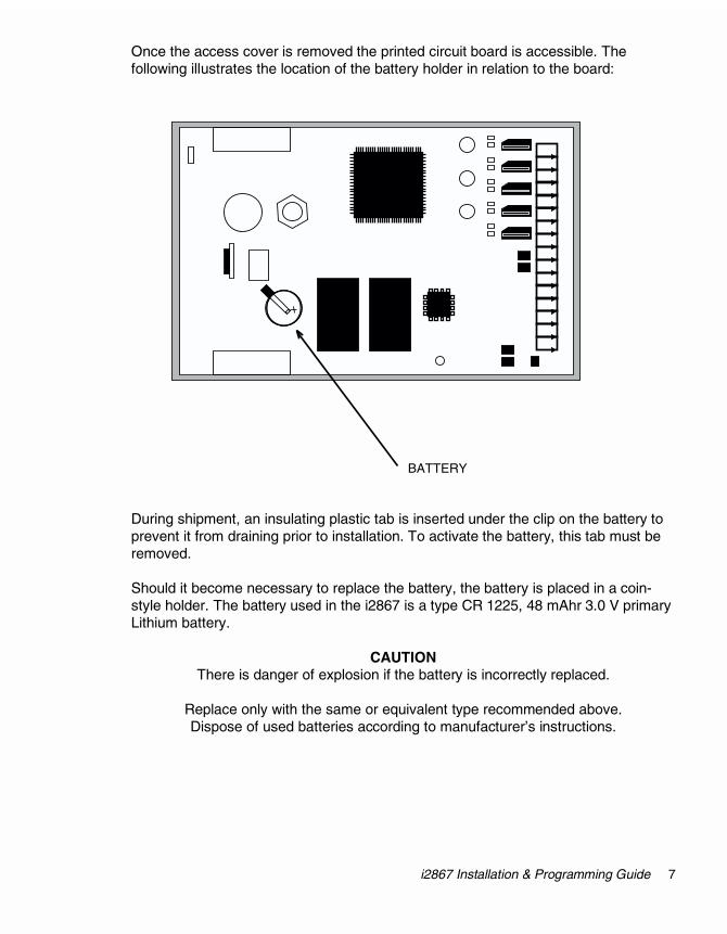
Once the access cover is removed the printed circuit board is accessible. The following illustrates the location of the battery holder in relation to the board: During shipment, an insulating plastic tab is inserted under the clip on the battery to prevent it from draining prior to installation. To activate the battery, this tab must be removed. Should it become necessary to replace the battery, the battery is placed in a coin-style holder. The battery used in the i2867 is a type CR 1225, 48 mAhr 3.0 V primary Lithium battery.
CAUTION There is danger of explosion if the battery is incorrectly replaced.
Replace only with the same or equivalent type recommended above. Dispose of used batteries according to manufacturer’s instructions.

8 Andover Controls Corporation
+-
INFINET PORT
5 4 3 2 1
54
32
1
+-
SHLD
12
34
5
UNIVERSALINPUTS
INFINET PORT
24VAC0.17A, 4VA 50/60HZ
L
IN1IN2
IN3IN4 RET
X2
X1
5 4 3 2 1
AC LinePower
24 VAC Step-DownTransformer Optional 39V Varistor
for extremely noisy environments
White orGreen
Black
i2867
Optional Varistorchoose a voltage rating appropriate to the
input voltage applied. i.e 130V or 250V
24VAC Connection The i2867 controller is powered by an external 24 VAC source. This power supply is connected via two terminals located on the Power/Communications connector. The unit should receive power from its own independent, 24 VAC +10% -15%, 50 or 60 Hz, 10 VA, un-switched circuit. The Power/Communications connector is located on the top of the module case (as viewed from the front) and consists of five pins. The signals within that connector are as follows:
PIN Function 5 24 VAC
4 (Earth GND)
3 Infinet Shield
2 Infinet -
1 Infinet +
Connect 24VAC as shown below:

i2867 Installation & Programming Guide 9
The 24 VAC connection consists of both terminals from the secondary of a power-line to 24 VAC transformer. Connection to the Controller is through push-on quick-disconnect screw type connector that is supplied with the Controller. The ground wire at the transformer should not exceed 12” in length and it must be connected to a good earth ground. The screw that connects the ground wire with earth ground shall have a green colored head that is hexagonal, slotted or both. Powering Multiple i2867 Controllers Unless all the i2867 controllers you intend to power are resident in the same cabinet, it is imperative that you use a separate transformer for each controller. When you attempt to power multiple remotely located controllers from a single power source the voltage drop caused by the current draw per controller (realize that the actuator may be using power from the controller as well) results in marginal operation and in most cases prevents proper communications between controllers.
Warning
Make sure that 24 VAC is not connected to the power cable while you are wiring the controller, or you could receive an electrical shock that is life-threatening.

10 Andover Controls Corporation
Building Ground Requirements Be sure that all equipment from Andover Controls is grounded to true Earth ground. True Earth ground protects the equipment from transients and other power surges in the area. We cannot guarantee that the controller system will operate as documented without a properly grounded installation.
An example of a sub-standard ground is a galvanized steel cold water pipe. As the pipe corrodes, it does not act as a true ground. The corrosion acts as an insulator, raising the potential of the pipe with respect to the ground. When lightning strikes in the area of the installation, it drastically changes the potential of the Earth. Since properly grounded Andover Controls units respond to changes in potential more rapidly than poorly grounded electrical systems, a poorly grounded building tries to reach ground through the Andover Controls system. The surge of current can destroy electronic components on the controller board. Surges of much lower potential than lightning also impact the reliability of the equipment. Inspecting the Ground Be sure to have your grounds inspected before you begin the installation process to be sure your municipality follows the National Electrical Code. Many municipalities do not follow the code and often have substandard electrical grounds.
Check your ground as follows:
Inspect the building power distribution panel for Earth-ground termination. If the ground termination is any of the following, it is not adequate and must be corrected:
Does not exist. Is connected to a corroded or galvanized pipe. Is connected using a small gauge wire (less than 14 AWG).
Be sure your Andover Controls cabinet is connected to the ground with a copper conductor that terminates at the distribution panel. Lightning Protection Although metal oxide varistors are built into the board to protect against power line transients, this protection is not sufficient to protect against lightning. Lightning arresters are required at each point where Infinet cables enter or exit a building. The following lightning arrester is recommended: Andover Controls # 01-2100-299, Two pair gas tube lightning arrester

i2867 Installation & Programming Guide 11
Infinet Network Connection The i2867 controllers include an interface to the Andover Controls proprietary Infinet network. Connection to the Infinet allows multiple controllers to communicate and be controlled by a larger ‘host’ controller. Connection to the Infinet requires access to an Infinet network cable. This cable consists of two wires and a shield. Infinet connections are done at the Power/Communications connector. To wire the Controller to the Infinet, follow the steps below: 1. Trim the outer jacket of the Infinet cable to reveal the internal wires.
2. Strip the insulation from the white* wire and loosen the screw at position 1.
3. Insert the stripped end of the white* wire into the pin 1 position (‘+’ receptacle) of the terminal block. Tighten the screw.
4. Strip the insulation from the black* wire and loosen the screw at position 2.
5. Insert the stripped end of the black* wire into the pin 2 position (‘-’ receptacle) of the terminal block. Tighten the screw.
6. Insert the shield wire into the pin 3 position (‘SHLD’ receptacle) of the terminal block. Tighten the screw.
* Wire colors are included for clarity. The colors of your cable may vary. However, make sure that all Infinet connections are consistent on their connections.
White (+)Black (-)
5 1234
Shield

12 Andover Controls Corporation
54321
Input Connections
Universal Inputs The i2867 Controller includes Andover Controls Universal Inputs that are unique in that they are software configurable to handle any one of a number of input types: Thermistor Voltage Digital/Counter
Input Wiring The actual input terminations are located on the bottom of the module. Connection is via a removable five-connection screw terminal plug. The signals within that connector are as follows:
PIN Function 1 IN1
2 IN2
3 IN3
4 IN4
5 RET (Common Return for all Inputs)
The inputs are labeled IN1 through IN4 and are followed by a connection labeled RET for the input signal return. Although there is only one return terminal (RET) supplied, it is recommended that a separate return wire be used for each input. All return wires should be crimped into one connection to the RET terminal.

i2867 Installation & Programming Guide 13
!
" # $
Wiring Concerns Do not remotely ground any part of the sensor wiring. Remote grounds connected to the i2867 return terminal could make the controller operate incorrectly or damage the equipment. The signal return is not true earth ground. It is an electronic reference point necessary to interpret the sensor properly.
It is recommended that you run input wiring in a conduit separate from AC power or output wiring and avoid long wiring runs.
For reliable input operation, follow these input wiring guidelines:
• Never lay wires across the surface of the printed circuit board.
• Wires should never be within 1 in. or 25 mm of any component on the printed circuit board.
• Use shielded input wire.
• Terminate the shield of the input wires at one end of the run only, preferably at the end where your controller is located.
• Be careful when stripping wire not to drop small pieces of wire inside the cabinet.
• Don’t run your input wiring in the same conduit with AC power.
• Don’t run your input wiring in the same conduit with your output wiring.
Caution Do not externally ground any input connected to the Controller. This may damage the unit. Signal return terminals are not connected to Earth Ground.
Input Pull-up Resistor Selection The i2867 inputs may be configured to include internal pull-up resistors. In some measuring instances it is desirable that there be no pull-up resistor. Instead of physically removing or cutting the resistor off the printed circuit board, the input module includes a pull-up resistor selection switch. When the switch is placed in the ‘enabled’ or ON position, the pull-up resistor is connected to the input line. When the switch is moved to the ‘disabled’ or OFF position, the pull-up resistor is removed from the circuit. The following is a schematic representation of the switch and its associated pull-up:

14 Andover Controls Corporation
Input Pull-up Resistor Switch Location The i2867 pull-up selection switch is located inside the plastic case, behind the status panel. You must remove the front of the case to access the location. To remove the front of the case, locate the small plastic tabs that hold the case halves together. Depress the tab on both sides and lift the case back as shown: Once you have accessed the board, the switch can be found as shown on the following diagram:
%%& ""!'()%"!*+
,
-.()% "()%

i2867 Installation & Programming Guide 15
Measuring Temperature (IN1 - IN4) All four of the i2867 inputs may be configured to sense temperature by configuring the controller’s inputs appropriately. This is done by setting the Electrical Type to either ACC Temp (DEG F) or ACC Temp (DEG C). Connect a resistive thermistor sensor to that input terminal. The following is a schematic representation of the connection: One lead connects to a numbered input terminal, the other to a return terminal.
When the input point is configured as a temperature input, the controller utilizes a look-up table to convert from a voltage reading to a temperature reading in degrees Fahrenheit or Celsius. To measure temperature, the pull-up resistor switch associated with this input must be enabled.
Caution Never apply a voltage to a thermistor—doing so alters the thermistor’s accuracy and reliability. In fact, it’s a good idea to replace any thermistor that has had any sort of voltage applied to it. Maximum Wire Runs for Thermistors To keep thermistor errors minimal, limit the length of wire runs to the maximum for the gauge wire you select. The following two pages include three tables that indicate the maximum length runs for wires of various gauges to keep errors within certain temperature limits when using thermistor elements.
IN x
RET
Thermistor

16 Andover Controls Corporation
Wire Gauges and Corresponding Maximum Runs for Sensing Temperatures Up to 70 °F (21 °C)
Gauge 1/2 °F (.28 °C) Error 1/4 °F (.14 °C) Error 1/10 °F (.06 °C) Error
#14 26,700 ft. 13,300 ft. 5,300 ft. 2.5 mm2 8150 m 4000 m 1600 m
#16 16,700 ft. 8,300 ft. 3,300 ft. 1.5 mm2 5120 m 2500 m 1000 m
#18 10,500 ft. 5,200 ft. 2,100 ft. 1.0 mm2 3200 m 1600 m 640 m
#20 6600 ft. 3,300 ft. 1,300 ft. 0.5 mm2 2000 m 1000 m 400 m
#22 4,100 ft. 2,000 ft. 800 ft. 0.35 mm2 1250 m 600 m 250 m
Wire Gauges and Corresponding Maximum Runs for Sensing Temperatures Up to 100 °F (38 °C)
Gauge 1/2 °F (.28 °C) Error 1/4 °F (.14 °C) Error 1/10 °F (.06 °C) Error
#14 12,600 ft. 6,300 ft. 2,500 ft.
2.5 mm2 3800 m 1900 m 760 m
#16 7,900 ft. 3,900 ft. 1,500 ft.
1.5 mm2 2400 m 1200 m 450 m
#18 5,000 ft. 2,500 ft. 1,000 ft.
1.0 mm2 1500 m 760 m 300 m
#20 3,100 ft. 1,500 ft. 600 ft.
0.5 mm2 950 m 450 m 180 m
#22 1,900 ft. 900 ft. 300 ft.
0.35 mm2 580 m 275 m 90 m

i2867 Installation & Programming Guide 17
Wire Gauges and Corresponding Maximum Runs for Sensing Temperatures Up to 150 °F (65 °C)
Gauge 1/2 °F (.28 °C) Error 1/4 °F (.14 °C) Error 1/10 °F (.06 °C) Error
#14 4,100 ft. 2,000 ft. 800 ft.
2.5 mm2 1250 m 600 m 240 m
#16 2,600 ft. 1,300 ft. 500 ft.
1.5 mm2 800 m 400 m 150 m
#18 1,600 ft. 800 ft. 300 ft.
1.0 mm2 500 m 240 m 90 m
#20 1,000 ft. 500 ft. 200 ft.
0.5 mm2 300 m 150 m 60 m
#22 600 ft. 300 ft. 100 ft. 0.35 mm2 180 m 90 m 30 m

18 Andover Controls Corporation
Measuring DC Voltages (IN1 - IN4) All four inputs may be configured to sense DC voltage by setting the Electrical Type to Voltage and connecting the input terminals to a DC voltage source within the range of the module’s input specifications. The following is a schematic representation of the connection: The plus lead connects to the numbered input terminal, the other to a return terminal. To measure voltage, the pull-up resistor switch associated with this input must be disabled.
Voltage Input Specifications
Voltage Range 0 to 5.115 V
Resolution 0.005 V
Accuracy +/–0.015 V
Input Impedance 10KΩ referenced to 5.120 V
Filtering Corner Frequency at 30 Hz, – 20db/decade
Calibration Permanent (factory)
IN x
RET
V
+
-

i2867 Installation & Programming Guide 19
Sensing Contact Closures (Digital) IN1 – IN5 Digital input points are designed to allow the monitoring of contact closures across an input (contact wired between the input and return). All five inputs can be configured as Digital Inputs.
To sense a digital input or contact closure, configure an input point with an Electrical Type of Digital. To sense contact closures, the pull-up resistor switch associated with this input must be enabled.
Note: When configuring a Digital point, there is a ‘Polarity’ attribute. If this attribute is enabled, readings are reversed: ‘On’ will occur when the contact is open, and ‘Off’ occurs when the contact is closed.
IN x
RET
ContactClosure

20 Andover Controls Corporation
Counting Pulsing Signals or Contact Closures
Counter inputs are designed to allow the monitoring of digital pulse trains or contact closures across an input just like digital inputs, but they accumulate a total of those closures and act like a counter. All four inputs can be configured as Counter Inputs. Interfacing is similar to a digital input, however, you set the Electrical Type attribute to Counter instead. To count signals or contact closures, the pull-up resistor switch associated with this input must be enabled. When using an input as a counter, you must take into account the frequency of the input signal being counted. Universal inputs do not allow for very high speed contact counting. This module allows counting up to a maximum of 4 Hz or 4 contact closures per second.
Minimum Pulse Width
The high period of the signal must be at least 125 milliseconds. The low period of the signal must be at least 125 milliseconds.

i2867 Installation & Programming Guide 21
Output Connections The i2867 Controllers include 5 Form A Triac outputs that can be used separately or be configured into Form K Tri-state outputs (2-max) with a free triac output remaining. Any two consecutive Triac outputs can be configured as a Form K output. Examples would be (OUT1 and OUT 2), (OUT3 and OUT4), (OUT2 and OUT3) and (OUT4 and OUT5). The Controller also includes 2 analog outputs. Note: When used with an Infinity network serviced by an SX8000 workstation, OUT 1 and OUT2 must be configured as a tri-state output. The SX8000 workstation assumes the i2867 is configured as an Infinet 1 TCX867 and therefore, these outputs cannot be used as separate triac outputs.
Output terminations are located on a sixteen-position removable screw terminal connector along the right side of the module.
54
32
1
+-
SHLD
12
34
5
UNIVERSALINPUTS
INFINET PORT
24VAC0.17A, 4VA 50/60HZ
L
IN1IN2
IN3IN4 RET
Output Terminations

22 Andover Controls Corporation
The outputs are grouped in pairs of two connector terminals per channel. Each Triac digital output presents a normally open single pole set of contacts.
The diagram below indicates where each output number is located in the terminal block. The Triac outputs are labeled ‘Digital Outputs’.
Connection Description
1. GND Form A Triac Output 2. OUT 1 3. GND Form A Triac Output 4. OUT 2 5. GND Form A Triac Output 6. OUT 3 7. GND Form A Triac Output 8. OUT 4 9. GND Form A Triac Output 10. OUT 5
11. RET Analog Outputs (0-10V) 12. OUT 6 13. OUT 7
14. RET Smart Sensor Bus Interface 15. IN 5 16. SPWR

i2867 Installation & Programming Guide 23
Digital Outputs (Form A Triacs) The i2867 includes five Form A Triac outputs. The following is a functional schematic representation of the connection:
These output contacts operate as a solid state relay. When the output is set to an ‘ON’ state, the contacts close allowing current to flow between the output terminals.
To use the Form A output in your system, configure an output point with an Electrical Type of Digital.
Output Rating: 0.5A, 24 VAC, (Cannot switch DC loads)
Output Accuracy: 0.1 sec. for Pulse Width Modulation (PWM) control
Output Protection: RC snubber on each output
Switching Loads with Triacs Although the Triac-based outputs provided with this unit appear as relay contacts in the schematics provided, they are actually solid-state switches that have limitations on the loads they can switch. AC vs. DC The first limitation is that they cannot be used with DC loads. A Triac switches AC only. Minimum Load Current The second limitation involves the minimum load current. In order for the Triac to switch it must have at least 30 ma of holding current from the load. If your load is less than 30 ma you can induce the required load by connecting a resistor across the load. Check the current draw specification on your field device, and if it does not meet this minimum, add a resistor in parallel with the device being driven sized to achieve the minimum loading. Use the following formulas to determine resistance and wattage: Resistance (ohms) = Voltage Power (Watts) = (Voltage)
2
Current Resistance

24 Andover Controls Corporation
Tri-State Output Adjacent outputs of the i2867 Controller module can be configured as Tri-state Triac outputs. The following is a schematic representation of a Tri-state output: In this example, Output 1 is the Tri-state output. The second output in a Tri-state pair is not addressable as a separate output. It is an integral part of the Tri-state circuit for Output 1.
Configure Output 1 with an Electrical Type of Tri-state.
Combining Form A Outputs as a Tri-State Output Adjacent output pairs:
OUT1 and OUT2 OUT2 and OUT3 OUT3 and OUT4 OUT4 and OUT5
can be combined to form a standard Tri-state output. The outputs are electrically connected as shown in the schematic for the built-in Tri-state output.
Configure the output point of the first point of a pair (i.e., OUT3 of the pair OUT3 and OUT4) with an Electrical Type of Tri-state.

i2867 Installation & Programming Guide 25
Analog Voltage Output The i2867 includes two Analog voltage outputs. Each voltage output is a ground-referenced signal with a range of 0-10VDC. The maximum output current is 5mA (2,000 ohms minimum load resistance). Ensure that the device being connected is either floating or at the same ground potential as the controller.
Configure the output point with an Electrical Type of Voltage.
Connect the device across the following terminals:
Although there is only one return terminal (RET) supplied, it is recommended that a
separate return wire be used for each output. All return wires should be crimped into one
connection to the RET terminal.
Note: The load resistance (of the external device) must be greater than or equal to 2 KΩ.

26 Andover Controls Corporation
Smart Sensor Bus Interface (IN5 & SPWR) The Smart Sensor is a room temperature sensor that includes an LCD or LED display and a 6-button programmable keypad.
The interface between the i2867 and the Smart Sensor Bus consists of three wires connected to the following positions on the sixteen-terminal output connector located on the right side of the Controller module:
14 RET 15 IN5 16 SPWR
The i2867 communicates with the display of the Smart Sensor device over a single wire (the SPWR connection).
The RET line is the return for both the communications line and the internal thermistor.
The IN5 signal is the active lead from the Smart Sensor thermistor and the keypad. It connects to the IN5 input to the i2867. Temperature readings and keypad activations from the Smart Sensor are read as Input 5.
Input 5 must be configured as a general Temperature input. The following illustrates the connection between the two units:

i2867 Installation & Programming Guide 27
Operation/Programming The i2867 Controller is a microcomputer that, along with the input and output circuitry, includes program memory and data memory. The hardware of the i2867 does nothing without being configured and programmed.
Key Concepts There are many concepts to learn; however, there are a few key ones that you need to understand before attempting to grasp the others. These key concepts are outlined below.
Workstation The user interacts with the system (either Continuum or Infinity) through a personal computer called the workstation. Workstation software called CyberStation or SX8000 is used to configure (set-up), program, monitor and operate the system.
Programming Programs in a BASIC-like language called Plain English are created on the workstation and downloaded to the controller where they run.
Configuration The configuration process is where the various settings for the controller are applied. Configuration information includes such things as the setting of each input type.
Points The control of equipment requires monitoring individual inputs and actuating individual outputs. In Infinity and Continuum systems, these discrete entities are referred to as ‘points’. You’ll see ‘output point’ or ‘input point’ referred to quite often.
In keeping with this tradition, internal places within a controller or workstation’s memory are also referred to as points. These software-based points may be temporary storage locations for set points or the memory location where the current date and time are stored.
Flash Memory Memory holds configuration data and the programs the controller uses during operation. Flash Memory is a kind of memory that has the ability to retain its contents even during a power failure. Flash does not require batteries to retain this information.
Database The information that describes the structure and operation of your building is stored in a software database. The values of each point in the system, the settings for limits, the configuration of the hardware and more are contained within this software structure.
The database is the key to the entire system.

28 Andover Controls Corporation
Configuration Process The controller is shipped from the factory with the operating system firmware pre-programmed into its program memory. This firmware allows the controller to communicate with a workstation so that it can be further configured and programmed to meet the requirements of its intended task.
Once the controller is physically installed at your site it must be configured and programmed. The following information is presented as an overview of the process. Detailed descriptions of configuration can be found in the Continuum Configurator’s Guide (for Continuum systems) or the Infinity SX8000 Programmer’s Guide.
After configuration, the new controller will be visible in the database tree shown in the workstation explorer window. The following screen shot illustrates the new controller after creation. This particular screen comes from a Continuum workstation: The i2867 is the controller named “New_controller”. As an Infinet II controller, its icon is different from an Infinet I controller.
The folders shown beneath the icon are made visible by clicking the small plus symbol next to the icon. These folders hold other programmable entities within the controller.
Magic Variables There are several “magic” variables that are used to set up the operation of the flash memory. On Continuum systems (v 1.5 or higher), these variables are automatically created as System Variables. On Infinity systems or earlier Continuum systems, these variables are manually created numerics.

i2867 Installation & Programming Guide 29
Controller Memory Infinet II controllers such as the i2867 have two distinct program memories. One is dedicated to the lower-level operation of the controller and the other holds user-defined items such as point data and Plain English programs. Flash Files The operating system area contains what is known as the controller’s operating system firmware. This memory is of the flash variety; it requires no power to retain its information. Periodically, newer versions of the operating system are released. You can find and download the latest version of the operating system from the Andover Controls Technical Support web site. These new versions consist of one or more “flash files”. Workstation software (Continuum CyberStation 1.5 or higher) includes provisions for you to upload these flash files directly to the controller. Application Memory Plain English programs and point data are stored in Application Memory. This memory is backed up with a battery to guard against power failure. The controller includes an extra Flash Memory for storing some of the Application data as well. This Flash Memory can be commanded to store the configuration data contained in the battery-backed memory as an extra insurance against loss. Advantages to Having the Application Data Flash Memory Initially it may seem redundant to include a flash memory along with battery-backed memory to hold application data. However, it is this redundancy that makes its addition attractive. Although it is unlikely that the battery will fail or that the data in that memory will become corrupted, it is an extra layer of protection for your configuration data to be able periodically to lock it into flash. Limitations of Flash Memory? Flash memory circuits are rated for a maximum of 100,000 write operations. You would not use flash memory for the main system RAM in your personal computer. Its inclusion in the controller is for storing completed configurations and a snapshot of data at a particular time. When used in this manner, the memory should last the lifetime of the product. To give you an idea of how many operations are available, consult the following examples: Write to flash Number of operations available 1 time per day 274 years 10 times per day 27 years If you’re really worried about exceeding the maximum number of writes, the controller includes an automatic software-based “circuit breaker” that warns you every 10,000 write operations.

30 Andover Controls Corporation
Start-up From Power Failure With so many memory options available to the controller for storing critical data, we thought it would be equally helpful to provide a few options for retrieving that data upon start-up from a power down condition. Although the controller has a default start-up mode, there are two other start-up sequences that you can choose. Possible Restart Conditions The following describes the three types of conditions a controller may encounter during a restart from a power failure:
Cold Start: The controller powers up from reset with no user objects or configuration in place.
Cool Start: The controller powers up from reset and restores the user configuration from Flash memory. It is assumed that a configuration was explicitly saved by the user at some point prior to power down. Point log data is not restored (with the exception of manual arrays on setpoints), Plain English programs are started at their beginning, and user points, whose SetPoint attribute has been set, have their values restored. Cool start can be thought of as a “self reload”.
Warm Start: The controller powers up from reset with a user configuration in place. The user configuration is that which was present in the controller and preserved due to the battery-backed memory when it was reset and/or power was lost. Point log data is preserved, Plain English programs are restarted at the same logical line that was being interpreted when the controller shut down, and all user points have their values restored. Warm start is functionally similar to an Infinet 1 warm start.
Overview of Available Restart Modes One of the settings during the controller definition phase of the configuration process is to determine the power restart mode. The following modes are available:
ACCWarmStartOnly The controller, upon recovery from reset, attempts a warm start; if that fails, proceeds with cold start.
ACCCoolStartOnly The controller, upon recovery from reset, attempts a cool start; if that fails, proceeds with cold start.
ACCWarmToCool The controller, upon recovery from reset, attempts warm start; if that fails, attempts a cool start; if that fails, proceeds with cold start. This is the default mode for the controller.

i2867 Installation & Programming Guide 31
Detailed Description of Restart Modes
Warm Start Only
Selected by:
Continuum System Variable: ACCRestartMode = ACCWarmStartOnly
Infinity Numeric: INFRestartMode = 0
In this mode, after a reset the controller examines the database in its internal RAM, attempts to correct any data corruption that may have been caused by an untimely reset/power loss, validates the database and attempts to use it if it is found to be valid.
• Point values (with the exception of input points) are restored.
• Input point values are purged and a fresh sample is obtained from the hardware before the Scanner runs.
• Output points are marked for hardware update such that their values will be refreshed to the hardware upon completion of the Scan (pulsed output values are assumed to have expired).
• All log data are retained.
• Plain English programs, that were running when the system went down, are re-started at the same logical line that was “CurrentLine” when the controller shut down. The Status, and State attributes are left unchanged. Line start times are left at whatever value they had when the controller went down and ts, tm, th, td will be incremented (from whatever value they had before power down) by the time delta imposed by the first time sync message after warm start. The elapsed time variables are actually computed values, hence their behavior is a side effect of the fact that the line start times are left unchanged.

32 Andover Controls Corporation
Cool Start Only
Continuum System Variable: ACCRestartMode = ACCCoolStartOnly
Infinity Numeric: INFRestartMode = 1
In this mode, the user database is backed-up to the User Backup Area of Flash memory upon user command only (manually). When the controller powers up after a reset, it examines the backup area in Flash memory, and if a valid backup is found, the data is restored to RAM. Certain portions of the data are re-initialized:
• Point values whose SetPoint attribute are TRUE have their values restored
• Input point values are purged and a fresh sample obtained from the hardware before the Scanner runs.
• Output points are purged.
• All automatic log data are purged
• Manual array data are retained for setpoint variables only.
• The CurrentLine attribute of Plain English programs is set to its first line. The program is run ONLY if the AutoStart attribute is TRUE. The State attribute is restored and its value observed.
Warm to Cool
Continuum System Variable: ACCRestartMode = ACCWarmToCool
Infinity Numeric: INFRestartMode = 2
In this mode, the user database is backed-up to the User Backup Area of Flash memory only when the user specifically requests a backup. When the controller powers-up after a reset, it examines the database in RAM, attempts to correct any data corruption that may have been caused by an untimely reset/power loss, validates the database (against things like bad pointers etc.) and attempts to use it if it is found to be valid. If this fails, it examines the User Backup Area of Flash memory, and if a valid backup is found then data is restored to RAM (cool start).

i2867 Installation & Programming Guide 33
Setting the Restart Mode On Continuum Systems:
When you define the controller using the Continuum CyberStation, a system variable called ACCRestartMode is automatically created in the controller. Through the explorer, open the System Variables folder and open the ACCRestartMode variable.
In the editor window you select the desired mode from the three modes previously mentioned.
On Infinity Systems:
Defining the controller on an Infinity system using the SX8000 requires you to manually create a numeric variable: INFRestartMode. After creation you need to set this variable as follows: Mode Set INFRestartMode to:
Warm Start Only 0
Cool Start Only 1
Warm To Cool 2

34 Andover Controls Corporation
Flash Memory Backup Variables and Tools With the restart mode set to CoolStartOnly or WarmTo Cool, you have the option of backing up your database to the internal Application Flash Memory. There are several status variables that can be monitored to determine the current state of the information in the flash area. StatusFlash Indicates the state (empty, full or failure) of the Flash
memory device. In this case “full” indicates that a valid database is present.
StatusBackup Indicates the operational state (backup needed, backup
done, backup in progress, etc.) of the memory. It also includes provisions to initiate a backup operation.
FlashWRCount Stores a running tally of the number of write operations
performed on the flash memory. There are two features that prevent loss of operations: Flash Circuit Breaker Prevents you from unintentionally performing more write
operations than the flash memory allows. Automatic Notification of Backup Needed Visual indication in the Continuum Explorer of the need to
backup a controller.

i2867 Installation & Programming Guide 35
Using the StatusFlash Variable The StatusFlash variable indicates the current state (empty, full or failure) of the Flash memory device. The controller stores status information into this variable. On Continuum Systems:
A system variable called ACCStatusFlash is automatically created when the controller is defined.
ACCStatusFlash can have the following values:
ACCFlashEmpty There is no valid database in Flash memory
ACCFlashValid There is a valid database in Flash memory
ACCFlashFailure An error was encountered while trying to perform a backup to Flash. In this state, the data in flash is unusable
On Infinity Systems:
A numeric called INFStatusFlash must be manually created prior to its use.
INFStatusFlash can have the following values:
0 (zero) There is no valid database in Flash memory
1 There is a valid database in Flash memory
2 An error was encountered while trying to perform a backup to Flash. In this state, the data in flash is unusable

36 Andover Controls Corporation
Using the StatusBackup Variable The StatusBackup variable indicates the operational state (backup needed, backup done, backup in progress, etc.) of the memory. It is also used to initiate a backup operation. The controller stores status information into this variable and the user initiates a manual backup operation through this variable. Note: The CyberStation (v 1.5 or higher) user interface includes the ability to command a flash backup as well as the method presented below. On Continuum Systems:
A system variable called ACCStatusBackup is automatically created when the controller is defined.
ACCStatusBackup, when used as an indicator, can have the following values:
ACCBackupDone A backup to Flash memory has been successfully completed, or the controller has not been configured.
ACCBackupNeeded A configuration item has changed value since the last successful backup to Flash memory.
ACCBackupInProgress A backup to Flash memory operation is underway. Note: The database is available on a read-only basis during the backup operation.
ACCBackupDisabled The database has been saved to Flash memory 10,000 times and the user has attempted further backup operations without re-setting the Flash Circuit Breaker (see BackupEnable). For as long as this condition persists, further backup operations are disabled.
ACCBackupInactive The system has been placed in WarmStartOnly mode and therefore, Flash user backup area is not available for use.
ACCStatusBackup, when used to initiate a backup can have the following values:
ACCBackupEnable A command from the user. This allows you to override the Flash Circuit Breaker and perform further backup operations. Further backup operations will be uninhibited until an additional 10,000 Flash write cycles have been incurred.
ACCBackupNow A command from the user. This causes the system to initiate a backup of the current database to Flash memory.

i2867 Installation & Programming Guide 37
Using the StatusBackup Variable (continued)
On Infinity Systems:
A numeric called INFStatusBackup must be manually created prior to its use.
INFStatusBackup, when used as an indicator can have the following values:
0 (zero) A backup to Flash memory has been successfully completed.
1 A configuration item has changed value since the last successful backup to Flash memory.
3 A backup to Flash memory operation is underway. Note: The database is available on a read-only basis during the backup operation.
4 The database has been saved to Flash memory 10,000 times and the user has attempted further backup operations without re-setting the Flash Circuit Breaker (see BackupEnable). For as long as this condition persists, further backup operations are disabled.
6 The system has been placed in WarmStartOnly mode and therefore, Flash user backup area is not available for use.
IMPORTANT NOTE: You must use the command line to write to the INFStatusBackup variable. Do not use the editor window in the SX8000, CyberStation or the terminal interface within a CX to initiate a backup operation.
INFStatusBackup, when used to initiate a backup can have the following values:
5 A command from the user. This allows you to override the Flash Circuit Breaker and perform further backup operations. Further backup operations will be uninhibited until an additional 10,000 Flash write cycles have been incurred.
2 A command from the user. This causes the system to initiate a backup of the current database to Flash memory.

38 Andover Controls Corporation
Using the FlashWRCount Variable The FlashWRCount variable Stores a running tally of the number of write operations performed on the flash memory. The controller stores the count information into this variable. On Continuum Systems:
A system variable called ACCFlashWRCount is automatically created when the controller is defined.
On Infinity Systems:
A numeric called INFFlashWRCount must be manually created prior to its use.

i2867 Installation & Programming Guide 39
I/O Point Assignments The i2867 can be programmed using the following point assignments: Function Input Point Assignment Electrical Type Input 1 1 * see note 1 Input 2 2 * see note 1 Input 3 3 * see note 1 Input 4 4 * see note 1 Input 5 5 * see note 2 Function Output Point Assignment Electrical Type Output 1 1 * see note 3 Output 2 2 * see note 3 Output 3 3 Digital, Tri-State Output 4 4 Digital, Tri-State Output 5 5 Digital, Tri-State Output 6 6 Voltage Output 7 7 Voltage * Note 1: valid E-Types are:
Voltage ACC_TEMP_DEGF ACC_TEMP_DEGC Digital Counter
* Note 2: valid E-Types are: Digital ACC_TEMP_DEGF ACC_TEMP_DEGC
* Note 3: valid E-Types are: When using CyberStation: Digital, Tri-State When using SX8000: Tri-State only

40 Andover Controls Corporation
Pre-Operation Checks 1. Make sure the internal battery is present and the protective tab is removed.
2. Make sure the 24VAC power is wired properly. Check to be sure that both wires have been connected.
3. Make sure the controller has a true earth ground.
4. Make sure you have used the proper cables and wires at correct lengths.
5. Make sure the Infinet cables and shields has been properly wired.
Initial Power-Up 1. Enable the AC power source (or close the power connection). The controller starts
automatically. If the controller has been off, outputs remain off. If you have pressed the internal RESET button, outputs turn off.
2. The CPU indicator flashes five times per second during normal operation.
3. If the CPU indicator flashes two times per second, the CPU has failed an internal test. In this case, recheck your connections and contact your Andover Controls representative. Indicators are located on the Access Panel found behind the module door.

i2867 Installation & Programming Guide 41
FUSE
Troubleshooting
CPU Indicator Is Not Blinking If the CPU indicator is not blinking then the unit is not operating. This could be due to the loss of primary AC power or other internal disfunction.
Check that 24VAC is available and connected properly to the power terminals. This can be done using a multimeter reading the voltage across the 24VAC and GND terminals.
If power appears to be OK, remove power and all other connections from the unit. The fuse within the unit may have failed. To access the fuse the controller housing itself must be disassembled. The housing consists of two pieces that are snapped together.
Follow the illustrations below to open the housing and gain access to the fuse area of the printed circuit board: Remove the plug-in power fuse component and check it for continuity with an Ohm meter. If the fuse is blown, replace it with a similar 2 Amp fuse (it resides in a socket). After replacement, take care re-mounting the cover.
Depress tabs found on bothsides of the case

42 Andover Controls Corporation
Unit Appears Functional But Is Not Responding To CX Controller If the CPU indicator is blinking normally chances are that the unit is operational. However, in that the i2867 is a programmable unit, it is possible that there is a programming problem. Monitoring Infinet Activity Infinet communications can be monitored simply by observing the status of the TD (transmit) and RD (receive) LED indicators viewable from the Access Panel. During Infinet communications, both of these LEDs should show activity. One Input or Output Appears to Be Dysfunctional If the CPU indicator is operating and other inputs/outputs are operating properly there could be two reasons for the failure: • The Input or Output has been damaged. In this case contact an Andover
Controls representative for assistance.
• If this is the first time using the controller, perhaps the program controlling the input/output is not correct. Re-check your program.
Internal Reset Button Should the controller appear to be non responsive and all other attempts to revive it fail, try pressing the Reset button. The button is located behind the Access Panel.
Restart Switch behind panel

i2867 Installation & Programming Guide 43
To access the button, the module cover must be opened and the electronics access cover must be removed. The access cover is secured via two force fitting plastic tabs. To remove the access cover after the main cover is opened, gently pry the cover outward using your thumb and forefinger while lifting the cover. As shown below:

44 Andover Controls Corporation

I2867 Installation & Programming Guide

30-3001-796 i2867 Installation & Programming Guide Rev B