controller optimisation, ag 0100 · optimisation procedures must be carried out in observance of...
TRANSCRIPT

EN AG 0100
Controller Optimisation Guideline for AC motors - CFC Closed-Loop

Controller Optimisation – Guideline for AC motors - CFC Closed-Loop
2 AG 0100 EN-3216
Pos: 3 /Appli kationen/[AG 0100] R egler optimi erung ASM - CFC Closed-Loop/0. Pr olog/D okumentation - Versionsliste [AG 0100] @ 5\mod_1400484697119_388.docx @ 132290 @ @ 1
Documentation Title: AG 0100 Order – No.: 6047502 Series: SK 200E, SK 500E FI series: SK 200E, SK 210E, SK 220E, SK 230E,
SK 205E, SK 215E, SK 225E, SK 235E, SK 520E, SK 530E, SK 535E,SK 540E, SK 545E
FI types: SK 2xxE-250-112-O ... SK 2xxE-750-112-O (0.25 - 0.75 kW, 1 ~ 100 - 120 V, output 3 ~ 230 V)
SK 2xxE-250-123-A ... SK 2xxE-111-123-A (0.25 - 1.1 kW, 1 ~ 220 - 240 V)
SK 2xxE-250-323-A ... SK 2xxE-112-323-A (0.25 - 11.0 kW, 3 ~ 220 - 240 V) 1
SK 2xxE-550-340-A ... SK 2xxE-222-340-A (0.55 - 22.0 kW, 3 ~ 380 - 500 V) 2
SK 5xxE-250-112-O ... SK 5xxE-750-112-O (0.25 - 0.75 kW, 1~ 115 V, output 3~ 230 V)
SK 5xxE-250-323- ... SK 5xxE-221-323- (0.25 - 2.2 kW, 1/3 ~ 230 V)
SK 5xxE-301-323- ... SK 5xxE-182-323- (3.0 - 18.0 kW, 3 ~ 230 V)
SK 5xxE-550-340- ... SK 5xxE-163-340- (0.55 - 160.0 kW, 3 ~ 400 V)
1) Size IV (5.5 – 11.0 kW) only in the versions SK 2x0E 2) Size IV (11.0 – 22.0 kW) only in the versions SK 2x0E
Version list Title, Date
Order number Version Remarks
AG 0100, Nov. 2014
6047502 / 4714 1.0 First edition, based on the manuals BU 0200 GB / 2314, BU 0210 GB / 2509, BU 0500 GB / 1013, BU 0505 GB / 1013, BU 0510 GB / 3911
AG 0100, April 2015
6047502 / 1615 1.0 Revised edition, based on the manuals BU 0500 GB / 0715, BU 0505 GB / 0715 • General corrections • Adaptation of various parameters
AG 0100, August 2016
6047502 / 3216 1.1 Revised edition, based on the revised manual BU 0200 GB / 1216 • General corrections and structure modifications • Further sections implemented
Table 1: Version list AG 0100 Pos: 6 /Allgemei n/Allgemei ngültige Modul e/H erausgeber @ 0\mod_1325779078002_388.docx @ 5270 @ @ 1
Publisher Getriebebau NORD GmbH & Co. KG Getriebebau-Nord-Straße 1 • 22941 Bargteheide, Germany • http://www.nord.com/ Fon +49 (0) 45 32 / 289-0 • Fax +49 (0) 45 32 / 289-2253
Pos: 7 /Appli kationen/0 Pr olog/0.2 Allgemeine Hi nweise @ 3\mod_1376473126903_388.docx @ 85905 @ 555 @ 1

General information
AG 0100 EN-3216 3
General information Copyright
Getriebebau NORD GmbH & Co. KG, all rights reserved
Copying, editing or communication of the content of this documents either as a whole or in part is prohibited without the explicit permission of Getriebebau NORD GmbH & Co. KG.
Right of modification
NORD GmbH & Co. KG reserves the right to amend the contents of the application descriptions at any time without prior notice.
Completeness and correctness
This application description is not binding and does not claim to be complete with regard to the structure and parameterisation of components.
Every care has been taken to ensure that the contents of this application description are correct. However, in case of deviations between the application description and other documentation (e.g. Manuals) the content of the other documentation has priority.
NOTICE Application
This application example is only valid in combination with the operating instructions of the respective frequency inverters and technology options. This is an essential prerequisite for the availability of all the relevant information required for the safe commissioning of the frequency inverter. Pos: 8 /Appli kationen/0 Pr olog/0.1 H aftungsausschluss @ 3\mod_1376467602238_388.docx @ 85881 @ @ 1
Exclusion of liability This application document is an aid for the installation and parameterisation of an application with NORD products. The description is based on an example for a specific application and can be used as orientation for comparable applications.
As this is an example, Getriebebau NORD GmbH & Co. KG does not accept any liability for injury or material damages and does not grant any warranty, either explicitly or implicitly with regard to the information contained in this application description. Pos: 9 /Appli kationen/[AG 0100 - AG 0101] allgemeing ültige M odul e/Allgemei n gültige Dokumente und Ü berschriften/Hinweis zum Leitfaden [Ü 1 ohne Nr.] @ 7\mod_1433917662424_388.docx @ 223620 @ @ 1

Controller Optimisation – Guideline for AC motors - CFC Closed-Loop
4 AG 0100 EN-3216
Information about this guide Pos: 10 /Appli kationen/[AG 0100 - AG 0101] allgemeingül tige M odule/Allgemein g ültige D okumente und Überschriften/Hi nweis zum Leit faden @ 7\mod_1433917701116_388.docx @ 223651 @ 555555 @ 1
This application guide is primarily intended for planners as well as commissioning and service personnel, who are familiar with the use and function of electronic drive technology (motors and frequency inverters) from Getriebebau NORD. The guide is a recommendation for the step-by-step commissioning and parameterisation of the individual controller and function settings as well as the procedure for optimisation of the drive unit or controller.
The information and recommendations relate to currently available drive units and control components or controller settings, preferably standard products from Getriebebau NORD. The guide refers to current drive technology software and hardware versions, which were valid at the time of publication of this guide. Optimisation procedures must be carried out in observance of the current manuals and drive technology data sheets. The versions of the manuals and technical data sheets may differ.
Information and explanations for the use of this application guide are given below.
Structure symbols
Individual section areas and application steps are provided with the following structure symbols in order to provide "familiar" users with graphical or quicker orientation:
Identification Meaning
Step 1
The Step (1, 2, etc.) serves to provide "familiar" users with a quicker overview for the use of the guide. In places, the steps can also be used as cross-references, or as hyperlinks, see 1.3 "Overview (schematic procedure)".
Information
The Information indicates that the following is only stated as information for the corresponding area of the section and provides the user with detailed or helpful additional information.
Instructions
The Instructions indicate that in the following, the user is required to take action, e.g. for parameterisation, testing or optimisation.
Information & instructions
Information & Instructions indicate that in the following, helpful additional information as well as the requirement for action by the user is described.
Fig. 1: List of structure symbols
Cross-references and hyperlinks
For quicker and easier use of the guide, cross-references are prefixed with a symbol . With a mouse click on the cross-reference - see 10.1 "Manuals" the user can directly access the appropriate section, information or the relevant document.
In addition, hyperlinks (e.g.M7000 Electric Motors) are used, with which the user can directly access the relevant manual, data sheet, contact partner, etc. on the Getriebebau NORD homepage..

Information about this guide
AG 0100 EN-3216 5
User symbols
By means of certain hand symbols, etc. the user is presented with important indications of additional information, curves and the objective of the optimisation of the controller.
Observance and indication of important additional information
Definition and objective of the optimisation to be made
Partial success for an optimised curve for optimisation of controllers
Objective of an optimum curve for the optimisation of the controller
Fig. 2: List of user symbols
Symbols
Indication of further information Automatic parameter change Change to manual parameterisation Check the display * Footnotes / deviations, e.g. device types
[V] Unit of the parameter value [-01] Array No. 1 Function No. / Value
1 = Off Description of function, the function number corresponds to the name of the function
Fig. 3: List of symbols
Parameters
The indication of individual parameters has been selected so that parameters which are shown in "bold" type, e.g. Motor list P200 indicate their relevance within a section. If the parameter is not written in "bold" type, e.g. Weak field limit P320, this is only subordinate information, or is not explained further.
Due to certain configurations, the parameters are subject to certain conditions. The relevant / used explanation symbols are listed below:
Parameter No. [-Array] Name [Unit] Factory
setting Setting
related to parameter set (P1, ... , P4)
MOTOR DATA/ CHARACTERISTIC CURVE PARAMETERS NORD motor Third party motor
P240 (P) EMF voltage PMSM [V] 0 0 341 0 296
P241 [-01] Inductance PMSM (d axis) [mH] 20 20 22.6 20 24.3
P241 [-02] Inductance PMSM (q axis) [mH] 20 20 45.9 20 24.3

Controller Optimisation – Guideline for AC motors - CFC Closed-Loop
6 AG 0100 EN-3216
Parameter number
Parameters (P) depend on parameter sets, see Parameter P100, Supervisor parameters (S) depend on the setting, see Parameter P003
Array value and description of the array parameter
Parameter text: Name / meaning of NORD CON display text
Parameter unit
Default value (factory setting) of parameter
Parameter setting for NORD motors
Parameter setting for third party motors
Usage symbols, see Symbols
Fig. 4: List of parameter indications
Names of parameters and functions
In the following, for example, a parameter is described with its name, number and with the corresponding selected function (number and name):
Motor list P200 with selection of the function 109 = 3.0 kW 400 V 100T2/4
Parameter name
Parameter number
Function number
Description of function / Name of function or NORD CON display text
Fig. 5: Overview of names of parameters and functions === Ende der Liste für Textmar ke Copyright ===

Overview for experienced user
AG 0100 EN-3216 7
Overview for experienced user === Ende der Liste für Textmar ke Inhaltsverzeichnis ===
1 Introduction ............................................................................................................................................... 14 1.3 Overview (schematic procedure) ..................................................................................................... 19
2 Hardware .................................................................................................................................................... 22 2.2 Asynchronous motors (ASM) ........................................................................................................... 23 2.3 Frequency inverter - motor assignment ............................................................................................ 23
3 Basic Commissioning ............................................................................................................................... 28 3.1 Operating display settings ................................................................................................................ 28 3.2 Motor data ........................................................................................................................................ 29
3.2.1 NORD – Motor type plates / Data sheet ............................................................................. 32 3.2.2 Motor identification ............................................................................................................. 33
3.3 Adjusting the slip compensation ....................................................................................................... 35 3.4 Optimisation of motor data ............................................................................................................... 35
3.4.1 NORD motors ..................................................................................................................... 35 3.5 Incremental encoder (IG) ................................................................................................................. 36
3.5.1 Parameterisation of encoders (IG) ...................................................................................... 36 3.5.5 Activating the speed control................................................................................................ 40
3.6 Absolute encoder (AG) ..................................................................................................................... 41 3.6.1 Parameterisation of CANopen encoders (absolute encoders) ............................................ 41 3.6.2 Parameterisation of the CANopen interface ....................................................................... 42
4 Current control .......................................................................................................................................... 46 4.1 Further settings ................................................................................................................................ 47 4.2 NORD CON ..................................................................................................................................... 48
4.2.1 Remote control ................................................................................................................... 48 4.2.2 Oscilloscope ....................................................................................................................... 49
4.3 Torque and field current controller ................................................................................................... 52 4.3.3 Criteria ................................................................................................................................ 54
4.4 Optimisation procedure .................................................................................................................... 55 5 Speed control ............................................................................................................................................ 58
5.1 Further settings ................................................................................................................................ 58 5.2 NORD CON ..................................................................................................................................... 60
5.2.1 Remote control ................................................................................................................... 60 5.2.2 Oscilloscope ....................................................................................................................... 61
5.3 Speed controller ............................................................................................................................... 63 5.3.3 Criteria ................................................................................................................................ 66
5.4 Optimisation procedure .................................................................................................................... 66 6 Position control ......................................................................................................................................... 69
6.1 Further settings ................................................................................................................................ 72 6.2 NORD CON ..................................................................................................................................... 74
6.2.1 Control ................................................................................................................................ 74 6.2.2 Oscilloscope ....................................................................................................................... 76 6.2.3 Device overview ................................................................................................................. 77
6.4 Position controller............................................................................................................................. 78 6.4.1 Parameterisation of the travel measurement system .......................................................... 79 6.4.2 Activating the position control ............................................................................................. 79 6.4.3 Positioning .......................................................................................................................... 79 6.4.5 Criteria ................................................................................................................................ 82
6.5 Optimisation procedure .................................................................................................................... 83

Controller Optimisation – Guideline for AC motors - CFC Closed-Loop
8 AG 0100 EN-3216
7 Slip compensation .................................................................................................................................... 85
7.1 Further settings ................................................................................................................................ 86 7.2 NORD CON ..................................................................................................................................... 87
7.2.1 Remote control ................................................................................................................... 87 7.2.2 Oscilloscope ....................................................................................................................... 88 7.2.3 Device overview ................................................................................................................. 89
7.3 Slip compensation ............................................................................................................................ 90 7.3.2 Criteria ................................................................................................................................ 92
7.4 Optimisation procedure .................................................................................................................... 92 8 Weak field controller ................................................................................................................................. 94
8.1 Further settings ................................................................................................................................ 97 8.2 NORD CON ..................................................................................................................................... 99
8.2.1 Remote control ................................................................................................................... 99 8.2.2 Oscilloscope ....................................................................................................................... 99
8.3 Weak field controller ....................................................................................................................... 101 8.3.3 Criteria .............................................................................................................................. 103
8.4 Optimisation procedure .................................................................................................................. 103 9 Parameter lists......................................................................................................................................... 106
9.1 Basic Commissioning ..................................................................................................................... 106 9.2 Current control ............................................................................................................................... 107 9.3 Speed control ................................................................................................................................. 108 9.4 Position control .............................................................................................................................. 109 9.5 Slip compensation .......................................................................................................................... 110 9.6 Weak field control........................................................................................................................... 111
Table of Contents
AG 0100 EN-3216 9
Pos: 12 /Allgemein/Steuermodul e/Inhaltsverzeichnis @ 0\mod_1317978518480_388.docx @ 4078 @ @ 1
Table of Contents === Ende der Liste für Textmar ke Inhaltsverzeichnis ===
1 Introduction ............................................................................................................................................... 14 1.1 Introduction to controller optimisation............................................................................................... 16 1.2 Field-orientated control .................................................................................................................... 17
1.2.1 No load current calculation ................................................................................................. 18 1.3 Overview (schematic procedure) ..................................................................................................... 19
2 Hardware .................................................................................................................................................... 22 2.1 System components......................................................................................................................... 22 2.2 Asynchronous motors (ASM) ........................................................................................................... 23 2.3 Frequency inverter - motor assignment ............................................................................................ 23 2.4 Encoder resolution selection ............................................................................................................ 24 2.5 Selection of the incremental encoder (IG) ........................................................................................ 24 2.6 Selection of absolute encoders ........................................................................................................ 26
3 Basic Commissioning ............................................................................................................................... 28 3.1 Operating display settings ................................................................................................................ 28 3.2 Motor data ........................................................................................................................................ 29
3.2.1 NORD – Motor type plates / Data sheet ............................................................................. 32 3.2.2 Motor identification ............................................................................................................. 33 3.2.3 Schematic circuit diagram .................................................................................................. 34
3.3 Adjusting the slip compensation ....................................................................................................... 35 3.4 Optimisation of motor data ............................................................................................................... 35
3.4.1 NORD motors ..................................................................................................................... 35 3.5 Incremental encoder (IG) ................................................................................................................. 36
3.5.1 Parameterisation of encoders (IG) ...................................................................................... 36 3.5.2 Encoder connection (IG) ..................................................................................................... 38 3.5.3 Function test of rotary encoders (IG) .................................................................................. 39 3.5.4 Incremental encoder (IG) with zero track ............................................................................ 39 3.5.5 Activating the speed control................................................................................................ 40
3.6 Absolute encoder (AG) ..................................................................................................................... 41 3.6.1 Parameterisation of CANopen encoders (absolute encoders) ............................................ 41 3.6.2 Parameterisation of the CANopen interface ....................................................................... 42 3.6.3 Connection of CANopen encoders (absolute encoder) ...................................................... 43 3.6.4 Function test of CANopen encoders (absolute encoders) .................................................. 44
4 Current control .......................................................................................................................................... 46 4.1 Further settings ................................................................................................................................ 47 4.2 NORD CON ..................................................................................................................................... 48
4.2.1 Remote control ................................................................................................................... 48 4.2.2 Oscilloscope ....................................................................................................................... 49
4.3 Torque and field current controller ................................................................................................... 52 4.3.1 Current control P components ............................................................................................ 53 4.3.2 Current control I components ............................................................................................. 53 4.3.3 Criteria ................................................................................................................................ 54
4.4 Optimisation procedure .................................................................................................................... 55 5 Speed control ............................................................................................................................................ 58
5.1 Further settings ................................................................................................................................ 58 5.2 NORD CON ..................................................................................................................................... 60
5.2.1 Remote control ................................................................................................................... 60 5.2.2 Oscilloscope ....................................................................................................................... 61
5.3 Speed controller ............................................................................................................................... 63 5.3.1 Speed control P component ............................................................................................... 65 5.3.2 Speed controller I component ............................................................................................. 65 5.3.3 Criteria ................................................................................................................................ 66
5.4 Optimisation procedure .................................................................................................................... 66

Controller Optimisation – Guideline for AC motors - CFC Closed-Loop
10 AG 0100 EN-3216
6 Position control ......................................................................................................................................... 69
6.1 Further settings ................................................................................................................................ 72 6.2 NORD CON ..................................................................................................................................... 74
6.2.1 Control ................................................................................................................................ 74 6.2.2 Oscilloscope ....................................................................................................................... 76 6.2.3 Device overview ................................................................................................................. 77
6.3 Function test of rotary encoders (IG) ................................................................................................ 78 6.4 Position controller............................................................................................................................. 78
6.4.1 Parameterisation of the travel measurement system .......................................................... 79 6.4.2 Activating the position control ............................................................................................. 79 6.4.3 Positioning .......................................................................................................................... 79 6.4.4 Position control P component ............................................................................................. 81 6.4.5 Criteria ................................................................................................................................ 82
6.5 Optimisation procedure .................................................................................................................... 83 7 Slip compensation .................................................................................................................................... 85
7.1 Further settings ................................................................................................................................ 86 7.2 NORD CON ..................................................................................................................................... 87
7.2.1 Remote control ................................................................................................................... 87 7.2.2 Oscilloscope ....................................................................................................................... 88 7.2.3 Device overview ................................................................................................................. 89
7.3 Slip compensation ............................................................................................................................ 90 7.3.1 Slip compensation value ..................................................................................................... 92 7.3.2 Criteria ................................................................................................................................ 92
7.4 Optimisation procedure .................................................................................................................... 92 8 Weak field controller ................................................................................................................................. 94
8.1 Further settings ................................................................................................................................ 97 8.2 NORD CON ..................................................................................................................................... 99
8.2.1 Remote control ................................................................................................................... 99 8.2.2 Oscilloscope ....................................................................................................................... 99
8.3 Weak field controller ....................................................................................................................... 101 8.3.1 P component of the weak field controller .......................................................................... 102 8.3.2 I component of the weak field control ............................................................................... 103 8.3.3 Criteria .............................................................................................................................. 103
8.4 Optimisation procedure .................................................................................................................. 103 9 Parameter lists......................................................................................................................................... 106
9.1 Basic Commissioning ..................................................................................................................... 106 9.2 Current control ............................................................................................................................... 107 9.3 Speed control ................................................................................................................................. 108 9.4 Position control .............................................................................................................................. 109 9.5 Slip compensation .......................................................................................................................... 110 9.6 Weak field control........................................................................................................................... 111
10 Further documentation ........................................................................................................................... 112 10.1 Manuals ......................................................................................................................................... 112 10.2 Technical Information / Data Sheets .............................................................................................. 112
10.2.1 TIs – Incremental encoder (IG) ......................................................................................... 112 10.2.2 TIs - CANopen absolute encoder (AG) ............................................................................. 113 10.2.3 TIs - Options / Accessory components ............................................................................. 113
11 Appendix .................................................................................................................................................. 114 11.1 Abbreviations ................................................................................................................................. 114

List of illustrations
AG 0100 EN-3216 11
Pos: 14 /Allgemein/Steuermodul e/Abbildungsverzeichnis @ 0\mod_1317978515699_388.docx @ 3917 @ @ 1
List of illustrations === Ende der Liste für Textmar ke Abbildungsverzeichnis ===
Fig. 1: List of structure symbols ............................................................................................................................... 4 Fig. 2: List of user symbols ...................................................................................................................................... 5 Fig. 3: List of symbols .............................................................................................................................................. 5 Fig. 4: List of parameter indications ......................................................................................................................... 6 Fig. 5: Overview of names of parameters and functions .......................................................................................... 6 Fig. 6: Current controller ........................................................................................................................................ 14 Fig. 7: Speed controller ......................................................................................................................................... 14 Fig. 8: Position control ........................................................................................................................................... 15 Fig. 9: Field weakening control .............................................................................................................................. 15 Fig. 10: Control loop .............................................................................................................................................. 16 Fig. 11: Current vector diagram ............................................................................................................................. 17 Fig. 12: Standard incremental encoders ................................................................................................................ 24 Fig. 13: Standard CANopen encoders ................................................................................................................... 26 Fig. 14: Example of motor type plate ..................................................................................................................... 29 Fig. 15: Example of a data sheet ........................................................................................................................... 30 Fig. 16: NORD motor (IE2) Data Sheet SK 112MH/4 ............................................................................................ 32 Fig. 17: RJ45 WAGO connection module .............................................................................................................. 43 Fig. 18: Control value curves ................................................................................................................................. 46 Fig. 19: NORD CON .............................................................................................................................................. 48 Fig. 20: Remote control of the current controller, setpoint and enabling ................................................................ 48 Fig. 21: Remote control of the current controller, setpoint and enabling ................................................................ 49 Fig. 22: Oscilloscope settings for trigger and scan rate / scan duration ................................................................. 49 Fig. 23: Resolution settings for the time axis, comment examples ........................................................................ 49 Fig. 24: Legend / Meaning of measurement functions ........................................................................................... 50 Fig. 25: Oscilloscope channel settings for the three measurement values ............................................................ 50 Fig. 26: Start the scope recording .......................................................................................................................... 50 Fig. 27: Initialisation phase of scope recording ...................................................................................................... 51 Fig. 28: Short circuit measurement of SK 200E frequency inverter ....................................................................... 55 Fig. 29: Curve for the P component of the current control ..................................................................................... 56 Fig. 30: Curve for the I component of the current controller .................................................................................. 57 Fig. 31: Remote control of the speed controller, setpoint and enabling ................................................................. 60 Fig. 32: Oscilloscope settings for trigger and scan rate / scan duration ................................................................. 61 Fig. 33: Resolution settings for the time axis, comment examples ........................................................................ 61 Fig. 34: Oscilloscope channel settings for the four measurement values .............................................................. 61 Fig. 35: Start the scope recording .......................................................................................................................... 62 Fig. 36: Example of an optimised speed controller curve ...................................................................................... 63 Fig. 37: Example with an excessive P component of the speed controller ............................................................ 64 Fig. 38: Curve for the P component of the speed control ...................................................................................... 67 Fig. 39: Curve for the I component of the speed control ........................................................................................ 68 Fig. 40: Position control movement profile ............................................................................................................. 71 Fig. 41: Standard control view ............................................................................................................................... 74 Fig. 42: Control of the speed controller, setpoint and enabling .............................................................................. 74 Fig. 43: Control of position control, control bits left setpoint position 0, right setpoint position 1 ........................... 75 Fig. 44: Oscilloscope settings for trigger and scan rate / scan duration ................................................................. 76 Fig. 45: Resolution settings for the time axis, comment examples ........................................................................ 76 Fig. 46: Oscilloscope channel settings for the four measurement values .............................................................. 76 Fig. 47: Start the scope recording .......................................................................................................................... 77 Fig. 48: Position control device overview, display settings .................................................................................... 77 Fig. 49: Overview of position control devices, display selection ............................................................................ 77 Fig. 50: Example of an optimised position controller curve .................................................................................... 80 Fig. 51: Example with P component of the position control too small (left) and too high (right) ............................. 81 Fig. 52: Curve for the P component of the position control .................................................................................... 83 Fig. 53: Remote control of slip compensation, setpoint and enabling .................................................................... 87 Fig. 54: Oscilloscope settings for trigger and scan rate / scan duration ................................................................. 88 Fig. 55: Resolution settings for the time axis, comment examples ........................................................................ 88 Fig. 56: Oscilloscope channel settings for the four measurement values .............................................................. 88 Fig. 57: Start the scope recording .......................................................................................................................... 89 Fig. 58: Slip compensation device overview, display settings ............................................................................... 89 Fig. 59: Slip compensation device overview, display selection .............................................................................. 89

Controller Optimisation – Guideline for AC motors - CFC Closed-Loop
12 AG 0100 EN-3216
Fig. 60: Diagram for optimum current / slip compensation .................................................................................... 90 Fig. 61: Example of optimised slip compensation .................................................................................................. 91 Fig. 62: Example with the slip compensation set too high (right) and too low (left)................................................ 91 Fig. 63: Slip compensation curve ........................................................................................................................... 93 Fig. 64: Control value curves ................................................................................................................................. 95 Fig. 65: Control value curves with long acceleration ramp .................................................................................... 95 Fig. 66: Remote control of the weak field control, setpoint and enabling ............................................................... 99 Fig. 67: Oscilloscope settings for trigger and scan rate / scan duration ............................................................... 100 Fig. 68: Resolution settings for the time axis, comment examples ...................................................................... 100 Fig. 69: Oscilloscope channel settings for the four measurement values ............................................................ 100 Fig. 70: Start the scope recording ........................................................................................................................ 100 Fig. 71: Example of an optimised weak field controller curve .............................................................................. 101 Fig. 72: Example with an excessive I component of the weak field controller ..................................................... 102 Fig. 75: Parameter list for basic commissioning .................................................................................................. 106 Fig. 76: Parameter list for optimised current control ............................................................................................ 107 Fig. 77: Parameter list for optimised current and speed control........................................................................... 108 Fig. 78: Parameter list for optimised current, speed and position control ............................................................ 109 Fig. 79: Parameter list for optimised current, speed, position control and slip compensation .............................. 110 Fig. 80: Parameter list for all optimised controllers, plus weak field controller ..................................................... 111

List of tables
AG 0100 EN-3216 13
Pos: 16 /Allgemein/Steuermodul e/Tabellenverzeichnis @ 0\mod_1317978519199_388.docx @ 4124 @ @ 1
List of tables === Ende der Liste für Textmar ke Tabellenverzeichnis ===
Table 1: Version list AG 0100 .................................................................................................................................. 2 Table 2: Flow chart for procedure .......................................................................................................................... 21 Table 3: System components ................................................................................................................................ 22 Table 4: Standard incremental encoders ............................................................................................................... 25 Table 5: Standard absolute encoders .................................................................................................................... 26 Table 6: SK 2xxE interface connection to the system bus ..................................................................................... 43 Table 7: Manuals ................................................................................................................................................. 112 Table 8: TIs – Incremental encoder (IG) .............................................................................................................. 112 Table 9: TIs - CANopen absolute encoder (AG) .................................................................................................. 113 Table 10: Options and accessory components .................................................................................................... 113 Pos: 19 /Appli kationen/[AG 0100 - AG 0101] allgemeingül tige M odule/1. Ei nlei tung/Ei nleitung [Ü 1] @ 7\mod_1431930768335_388.docx @ 219789 @ 1 @ 1
Controller Optimisation – Guideline for AC motors - CFC Closed-Loop
14 AG 0100 EN-3216
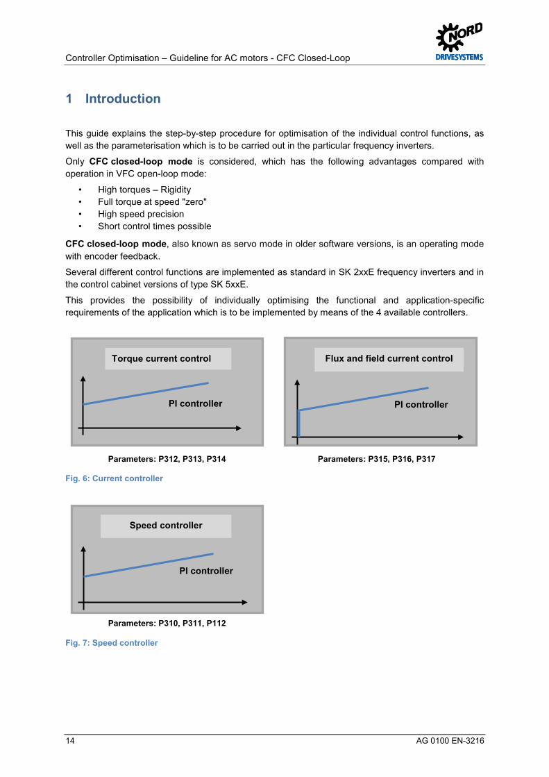
1 Introduction Pos: 20 /Appli kationen/[AG 0100] R egleropti mi erung ASM - CFC Cl osed- Loop/1. Einl eitung/Einl eitung @ 5\mod_1400491203953_388.docx @ 132318 @ @ 1
This guide explains the step-by-step procedure for optimisation of the individual control functions, as well as the parameterisation which is to be carried out in the particular frequency inverters.
Only CFC closed-loop mode is considered, which has the following advantages compared with operation in VFC open-loop mode:
• High torques – Rigidity • Full torque at speed "zero" • High speed precision • Short control times possible
CFC closed-loop mode, also known as servo mode in older software versions, is an operating mode with encoder feedback.
Several different control functions are implemented as standard in SK 2xxE frequency inverters and in the control cabinet versions of type SK 5xxE.
This provides the possibility of individually optimising the functional and application-specific requirements of the application which is to be implemented by means of the 4 available controllers.
Parameters: P312, P313, P314 Parameters: P315, P316, P317
Fig. 6: Current controller
Parameters: P310, P311, P112
Fig. 7: Speed controller
PI controller
Flux and field current control Torque current control
PI controller
Speed controller
PI controller

1 Introduction
AG 0100 EN-3216 15
Parameter: P611
Fig. 8: Position control
Parameters: P318, P319, P320
Fig. 9: Field weakening control
This guide for the optimisation of controllers uses the description for a decentralised SK 200E-401-340-A frequency inverter in combination with a 4.0 kW NORD asynchronous motor (ASM) using NORD CON oscilloscope recordings.
The correct connection of the components to the control and power terminals, as well as further information about the functions used can be obtained from the relevant manuals, see 10.1 "Manuals".
If the different names (e.g. connection terminals, parameter structure) are taken into account, this guide can also be used analogously for other performance levels of the decentralised SK 2xxE and ≥ SK 520E control cabinet frequency inverter types. Pos: 25 /Appli kationen/[AG 0100 - AG 0101] allgemeingül tige M odule/1. Ei nlei tung/Vor wort zur Regler opti mier ung [Ü 2] @ 7\mod_1431934227827_388.docx @ 220138 @ 2 @ 1
PI controller
Weak field controller
P controller
Position control
Controller Optimisation – Guideline for AC motors - CFC Closed-Loop
16 AG 0100 EN-3216
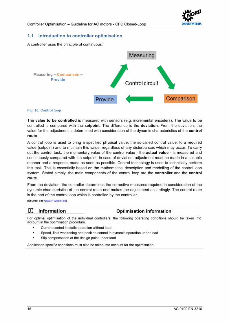
1.1 Introduction to controller optimisation Pos: 26 /Appli kationen/[AG 0100] R egleropti mi erung ASM - CFC Cl osed- Loop/1. Einl eitung/Vor wort zur R egleropti mi erung @ 5\mod_1400586860785_388.docx @ 133508 @ @ 1
A controller uses the principle of continuous:
Measuring – Comparison – Provide
Fig. 10: Control loop
The value to be controlled is measured with sensors (e.g. incremental encoders). The value to be controlled is compared with the setpoint. The difference is the deviation. From the deviation, the value for the adjustment is determined with consideration of the dynamic characteristics of the control route.
A control loop is used to bring a specified physical value, the so-called control value, to a required value (setpoint) and to maintain this value, regardless of any disturbances which may occur. To carry out the control task, the momentary value of the control value - the actual value - is measured and continuously compared with the setpoint. In case of deviation, adjustment must be made in a suitable manner and a response made as soon as possible. Control technology is used to technically perform this task. This is essentially based on the mathematical description and modelling of the control loop system. Stated simply, the main components of the control loop are the controller and the control route.
From the deviation, the controller determines the corrective measures required in consideration of the dynamic characteristics of the control route and makes the adjustment accordingly. The control route is the part of the control loop which is controlled by the controller. (Source: see www.rn-wissen.de)
Information Optimisation information For optimal optimisation of the individual controllers, the following operating conditions should be taken into account in the optimisation procedure.
• Current control in static operation without load • Speed, field weakening and position control in dynamic operation under load • Slip compensation at the design point under load
Application-specific conditions must also be taken into account for the optimisation. Pos: 32 /Appli kationen/[AG 0100 - AG 0101] allgemeingül tige M odule/1. Ei nlei tung/Fel dorientierte R egel ung [Ü2] @ 7\mod_1431934327112_388.docx @ 220169 @ 2 @ 1

1 Introduction
AG 0100 EN-3216 17
1.2 Field-orientated control Pos: 33 /Appli kationen/[AG 0100] R egleropti mi erung ASM - CFC Cl osed- Loop/1. Einl eitung/Feldorienti erte Reg elung @ 5\mod_1401974004349_388.docx @ 136092 @ @ 1
To begin with, some information about the motor model or field oriented control, also known as current vector control, in the frequency inverter.
In a rotor flux-oriented ASM model the 3-phase currents and voltages are converted to vectors which are comprised of the components "d" and "q".
The following diagram shows the orientation of the current vector to the magnetisation current Isd (rotor flux orientation) in the vector diagram.
Fig. 11: Current vector diagram
Is: Line motor current (≈ Nominal current) [A] Isd Flux-forming current (magnetisation current (≈ no load current)) [A] Isq: Torque-forming current (torque current (≈ rotor current) [A]
The current components Isd (flux-forming current, magnetisation current / ≈ Actual field current P721) and Isq (torque-forming current, ≈ Actual torque current P720) are normal to each other. Is is the total line current (≈ Actual current P719).
The following simplified relationships result in association with this:
𝑰𝑰𝒔𝒔 = (𝑰𝑰𝒔𝒔𝒔𝒔² + 𝑰𝑰𝒔𝒔𝒔𝒔²)
In the basic speed range, up to the rated frequency ISD = I0 = No load current.
Is: Line motor current (P203 / ≈ P719) [A] Isq: Torque-forming current or rotor current (≈ P720) [A] Isd: Flux-forming current or no load current (P209 / ≈ P721) [A]
If the flux-forming current / no load current is not known, it is automatically calculated by the frequency inverter and entered in the parameter No Load Current P209 Pos: 35 /Appli kationen/[AG 0100] R egleropti mi erung ASM - CFC Cl osed- Loop/1. Einl eitung/Leerlaufs trom Berechnung @ 5\mod_1402388883257_388.docx @ 136382 @ 3 @ 1

Controller Optimisation – Guideline for AC motors - CFC Closed-Loop
18 AG 0100 EN-3216
1.2.1 No load current calculation The No Load Current P209 is calculated with the following formula:
𝑰𝑰𝒔𝒔𝒔𝒔 = 𝑰𝑰𝟎𝟎 = 𝑰𝑰𝒏𝒏𝒏𝒏𝒏𝒏 ∙ 𝐬𝐬𝐬𝐬𝐬𝐬𝝋𝝋
Isd: Flux-forming current (Display ~P721) [A] I0: No load current (≈ P209) [A] Inom: Nominal motor current or line motor current (≈ P203) [A] cos φ: Motor cos phi (≈ P206) / Efficiency [-]
Therefore also:
𝑴𝑴 ≈ 𝚽𝚽 ∙ 𝑰𝑰𝒔𝒔𝒔𝒔 ≈ 𝚽𝚽 ∙ 𝑰𝑰𝒔𝒔 ∙ 𝐜𝐜𝐜𝐜𝐬𝐬𝝋𝝋 M: Torque [Nm] Φ: Magnetic flux [Wb] Is: Line motor current (Display ~P719) [A] Isq: Torque-forming current or rotor current (≈ P720) [A] cos φ: Motor cos phi (P206) / Efficiency [-]
In other words, if Isq increases, the torque M must also increase.
Information Torque M The torque M increases (theoretically) in the ratio of 𝐼𝐼𝑠𝑠𝑠𝑠
𝐼𝐼sqNom if, as agreed, the magnetic flux is constant.
Isq: Torque-forming current or rotor current [A] 𝑰𝑰𝒔𝒔𝒔𝒔𝒏𝒏𝒏𝒏𝒏𝒏: Torque-forming current under nominal conditions [A] Pos: 41 /Appli kationen/[AG 0100 - AG 0101] allgemeingül tige M odule/1. Ei nlei tung/Überblick (schematische Vorgehensweise) [Ü 2] @ 7\mod_1432017345551_388.docx @ 220670 @ 2 @ 1

1 Introduction
AG 0100 EN-3216 19
1.3 Overview (schematic procedure) Pos: 42 /Appli kationen/[AG 0100] R egleropti mi erung ASM - CFC Cl osed- Loop/1. Einl eitung/Ü ber blick (schemati sche Vorg ehensweise) @ 5\mod_1400504090154_388.docx @ 132496 @ @ 1
Step Description of procedure / Optimisation procedure Documentation / Section Further information
"Step 1"
Hardware
Manual BU 0200 Manual BU 0500 Manual BU 0505
2 "Hardware"
Setup and connection
– Installation and connection work – Power and control terminals – DIP switches – Motor connection ( check Y /) – Frequency inverter ↔ Assignment of asynchronous
motor – Encoder resolution selection – Selection of encoder system (IG / AG) – Selection of encoder type: Data for incremental and /
or absolute encoders, universal encoders
"Step 2"
Basic commissioning / Motor data
NORD CON – Manual BU 0000
Manual BU 0200 Manual BU 0500 Manual BU 0505
3.2 "Motor data"
Parameterisation according to motor list, type plate and data
sheet
– NORD CON parameterisation – Modification of operating displays – Selection of motor manufacturer or motor data – Motor list, motor type plate or data sheet
(contact the motor manufacturer if necessary) – Motor data / Characteristic curve parameter
(P2xx) – NORD- motor or third party motor parameter
identification (P220) (identification RS or identification motor)
– Stator resistance (P208), check display – Adjust slip compensation (P212)
"Step 3"
Incremental encoder (IG)
Manual BU 0200 Manual BU 0500 Manual BU 0505
3.5 "Incremental encoder
(IG)"
Parameterisation, connection and commissioning
– Incremental encoder data – Control parameter (P3xx) – Incremental encoder (P301) – Encoder with zero track – Sync. 0-pulse (P335) – Control terminals (P420 [-01] ... [-03]) – Connection, see Technical Data Sheet – Function test of IG rotary encoder – Speed feedback / Servo mode (P300)

Controller Optimisation – Guideline for AC motors - CFC Closed-Loop
20 AG 0100 EN-3216
Absolute encoder (AG)
Manual BU 0210 Manual BU 0510
3.6 "Absolute encoder (AG)"
Parameterisation, connection and commissioning
– CANopen combined absolute encoder with incremental encoder
– Absolute encoder data – Additional parameter (P5xx) and positioning
parameter (P6xx) – Encoder resolutions (P605) – Set CANopen parameters (P514 & P515) – Connection, see Technical Data Sheet – Function test for CANopen AG encoders
"Step 4"
Current control
4 "Current control"
Torque current controller (P312, P313, P314) Field current controller (P315, P316, P317)
– Adjust Absolute mini. Freq. (P505) – Adjust Flux delay (P558) – NORD CON Remote control – NORD CON Oscilloscope trigger, scan time, channel
settings, etc. – Torque current controller P (P312) – Torque current controller I (P313) – Field current controller P (P315) – Field current controller I (P316)
"Step 5"
Speed control
5 "Speed control"
Speed controller (P310, P311)
– Acceleration time (P102) – Jog frequency (P113) – Flux delay (P558) standard value – NORD CON Remote control – NORD CON Oscilloscope trigger, scan time, channel
settings, etc. – Speed Ctrl P (P310) – Speed Ctrl I (P311)
"Step 6"
Position control / Positioning
Manual BU 0210 Manual BU 0510
6 "Position control"
Position controller (P611)
– Activate position controller (P600) – Travel sensor system (P604 [01] & [02] & [03]) – Setpoint specification & setpoint mode (P610) – Positioning parameters (P607 to P609 & P612) – Positions (P613 [01] to [63]) – NORD CON Control – NORD CON device overview
trigger, scan time, channel settings, etc. – Position controller P (P611)

1 Introduction
AG 0100 EN-3216 21
"Step 7"
Slip compensation
7 "Slip compensation"
Slip compensation (P212)
– Jog frequency (P113) – NORD CON Remote control – NORD CON device overview as necessary – NORD CON Oscilloscope trigger, scan time, channel
settings, etc. – Operate the motor under normal operating conditions
/ at the operating point under the nominal load – Optimise Slip compensation (P212) by minimising
current
Information Operation in the weak field range For applications with operation in the weak field range the weak field controller should always be optimised as the last optimisation step of the weak field controller!
"Step 8"
Field weakening control
8 "Weak field controller"
Weak field controller (P318, P319, P320)
– Acceleration time (P102) – Maximum frequency (P105) – Jog frequency (P113) – NORD CON Remote control – NORD CON Oscilloscope trigger, scan time, channel
settings, etc. – P-Weak (P318) – I-Weak (P319)
Table 2: Flow chart for procedure
DANGER! Danger to life
The correctness of each individual commissioning step must be checked with a function test. Suitable precautions must be taken to prevent damage to the system or danger to persons if the system behaves incorrectly (e.g. brake control for lifting equipment, mechanical coupling of parallel drives, etc.) Pos: 46 /Appli kationen/[AG 0100 - AG 0101] allgemeingül tige M odule/2. H ardware/H ardware [Ü 2] @ 7\mod_1431930821993_388.docx @ 219820 @ 1 @ 1

Controller Optimisation – Guideline for AC motors - CFC Closed-Loop
22 AG 0100 EN-3216
2 Hardware Pos: 47 /Appli kationen/[AG 0100 - AG 0101] allgemeingül tige M odule/Str uktur module/Schritt 1 @ 7\mod_1434978549333_388.docx @ 227629 @ @ 1
Step 1
Pos : 48 /Appli kationen/[AG 0100 - AG 0101] allgemeingül tige M odule/Str uktur module/Infor mation @ 7\mod_1434979005376_388.docx @ 227948 @ @ 1
Information
Pos : 49 /Appli kationen/[AG 0100] R egleropti mi erung ASM - CFC Cl osed- Loop/2. H ardware/Har dwar e @ 5\mod_1401198154896_388.docx @ 134528 @ @ 1
The factory settings of frequency inverters supplied by Getriebebau NORD are pre-programmed with the default setting for standard applications with 4 pole asynchronous motors (ASM) with the same voltage and power. For use with motors with other powers or number of poles, the data from the type plate or data sheet of the motor must be entered.
In principle, the frequency inverters are operable in this configuration and can be further configured according to the requirements of the application,. This includes settings such as the encoder system, ramp times and interfaces and possibly the bus system configuration.
Configuration can be carried out to a limited extent with the integrated DIP switches (see 10.1 "Manuals").
Information Configuration via DIP switch
Mixing of DIP switch configuration and (software) parametrisation should be avoided. DIP switch settings for the frequency inverter have priority over parameter settings. Pos: 51 /Appli kationen/[AG 0100 - AG 0101] allgemeingül tige M odule/2. H ardware/Sys temkomponenten [Ü 2] @ 7\mod_1431931354744_388.docx @ 220099 @ 2 @ 1
2.1 System components Pos: 52 /Appli kationen/[AG 0100] R egleropti mi erung ASM - CFC Cl osed- Loop/2. H ardware/Systemkomponenten @ 5\mod_1400504056734_388.docx @ 132472 @ @ 1
For this guide, a 4 kW frequency inverter / motor combination was used for the test setup.
Number Designation Nominal ratings
1 Frequency inverter SK200E SK 200E-401-340-A 1 SK 200E connection unit SK TI4-2-200-3 1 4.0 kW, IE2 motor (ASM), 4 pole SK 112MH/4 TF IG22 1 Incremental encoder IG KU 10-30 V HTL IG22 / Resolution 2048 pulses 1 External brake resistor, 400 Ω, 100 W SK BRE4-1-400-100
Table 3: System components
With these system components, examples of the individual optimisations of the controllers are illustrated in the following sections on the basis of NORD CON oscilloscope images.
Information Version status Due to software updates, the parameters described in this guide may differ from those in the firmware version for the frequency inverter which is used. Because of this, care should be taken that both the current NORD CON version and the firmware version (see Software version parameter P707) correspond to that of the frequency inverter. Pos: 57 /Appli kationen/[AG 0100] R egleropti mi erung ASM - CFC Cl osed- Loop/2. H ardware/Asynchronmotoren (ASM) [Ü 2] @ 11\mod_1460368823842_388.docx @ 316964 @ 2 @ 1

2 Hardware
AG 0100 EN-3216 23
2.2 Asynchronous motors (ASM) Pos: 58 /Appli kationen/[AG 0100] R egleropti mi erung ASM - CFC Cl osed- Loop/2. H ardware/Asynchronmotoren (ASM) @ 11\mod_1460368803595_388.docx @ 316929 @ @ 1
Asynchronous motors (ASM) from Getriebebau NORD are specified according to the standard IEC 60034-30:2008 and can be operated both from the mains as well as by frequency inverters.
At present, Getriebebau NORD supplies asynchronous motors with the efficiency classes IE1, IE2 and IE3 in a power range from 0.12 kW to 160 kW.
All asynchronous motors from Getriebebau NORD are approved for operation with frequency inverters. However, at present on the motor data for efficiency class IE1 synchronous motors are stored in the frequency inverters. I.e. only IE1 asynchronous motors may be parameterised with Motor list P200! Third party motors and Getriebebau NORD IE2 and IE3 asynchronous motors, must be parameterised manually by the user.
Information Third party motors Asynchronous motors or brands from other manufacturers (i.e. so-called third party motors) can be operated by frequency inverters manufactured by Getriebebau NORD.
If necessary all frequency inverter – asynchronous motor combinations for third party motor operation should be technically checked in advance by Getriebebau NORD! Pos: 61 /Appli kationen/[AG 0100 - AG 0101] allgemeingül tige M odule/2. H ardware/Fr equenzumrichter - Motor Zuordnung [Ü 2] @ 7\mod_1431944081340_388.docx @ 220240 @ 2 @ 1
2.3 Frequency inverter - motor assignment Pos: 62 /Appli kationen/[AG 0100] R egleropti mi erung ASM - CFC Cl osed- Loop/2. H ardware/Frequenzumrichter - Asynchr onmotor Zuor dnung @ 7\mod_1431944154898_388.docx @ 220341 @ @ 1
Asynchronous motors can be operated with both decentralised frequency inverters from the SK 2xxE series, as well as by the control cabinet version SK 5xxE with all performance levels.
The selected allocation of the frequency inverter to the asynchronous motor is primarily made according to the power and the current.
Frequency inverter power ≥ Nominal motor power Nominal frequency inverter current ≥ Nominal motor current
NOTICE Drive unit load
The assignment of asynchronous motors to the particular frequency inverters applies for operation up to the nominal speed.
Higher speeds and overloads require special planning or consultation with Getriebebau NORD.
Failure to comply with this may cause damage to the motor or the gear unit due to impermissible loads on the components.
Information Third party motors In principle, asynchronous motors from Getriebebau NORD can be operated with frequency inverters from other manufacturers. However, the customer is responsible for the success of commissioning. Also, the performance of the motor, or the achievement of efficiencies which correspond to the efficiency classifications IE1, IE2, etc. depends on the frequency inverter and its function and settings. Pos: 64 /Appli kationen/[AG 0100 - AG 0101] allgemeingül tige M odule/2. H ardware/Auslegung Drehgeber Aufl ösung [Ü 2] @ 7\mod_1433427213057_388.docx @ 222310 @ 2 @ 1

Controller Optimisation – Guideline for AC motors - CFC Closed-Loop
24 AG 0100 EN-3216
2.4 Encoder resolution selection Pos: 65 /Appli kationen/[AG 0100 - AG 0101] allgemeingül tige M odule/2. H ardware/Auslegung Drehgeber Aüfl ösung @ 7\mod_1433426836884_388.docx @ 222278 @ @ 1
For the correct selection of the rotary encoder with regard to the maximum resolution, the maximum limiting frequency should be taken into account using the following rule-of-thumb:
𝒇𝒇max × 𝟔𝟔𝟎𝟎𝒏𝒏max
= 𝑬𝑬𝒏𝒏𝑬𝑬𝒏𝒏𝒔𝒔𝑬𝑬𝑬𝑬 𝑬𝑬𝑬𝑬𝒔𝒔𝒏𝒏𝒓𝒓𝒓𝒓𝒓𝒓𝒓𝒓𝒏𝒏𝒏𝒏
205000 [𝐻𝐻𝐻𝐻] × 60 [𝑠𝑠]nmax [rpm]
≥ Encoder resolution "[Pulse numbermax]"
205000 [𝐻𝐻𝐻𝐻] × 60 [𝑠𝑠]1500 [rpm]
= 8200 8200 ≥ 8192 Pulses Encoder resolution (nmax = 1500 rpm)
205000 [𝐻𝐻𝐻𝐻] × 60 [𝑠𝑠]3000 [rpm]
= 4100 4100 ≥ 4096 Pulses Encoder resolution (nmax = 3000 rpm)
fmax: maximum limiting frequency for digital inputs [Hz] nmax: maximum speed of motor [rpm]
All standard encoders defined by Getriebebau NORD, i.e. the recommended encoder systems and types enable "safe" operation within a very wide adjustment range (e.g. 0 to 100 Hz). I.e. the minimum Pulse numbermin has already been taken into account with regard to encoder resolution.
Pos: 66 /Appli kationen/[AG 0100 - AG 0101] allgemeingül tige M odule/2. H ardware/Auswahl Inkr ementaldr ehg eber (IG) [Ü 2] @ 7\mod_1435051508120_388.docx @ 228438 @ 2 @ 1
2.5 Selection of the incremental encoder (IG) Pos: 67 /Appli kationen/[AG 0100 - AG 0101] allgemeingül tige M odule/2. H ardwareAuswahl Inkremental drehgeber (IG) @ 5\mod_1407742539679_388.docx @ 146754 @ @ 1
The correct selection, parameterisation and connection of an HTL- incremental encoder (IG) to a decentralised SK 2xxE frequency inverter as well as a TTL incremental encoder or sine wave encoder (e.g. SIN/COS encoder) to an SK 53xE or SK 54xE control cabinet frequency inverter are described in greater detail in previous or further sections.
Various encoders with a cable length of 1.5 m are defined as standard incremental encoders by Getriebebau NORD:
Fig. 12: Standard incremental encoders
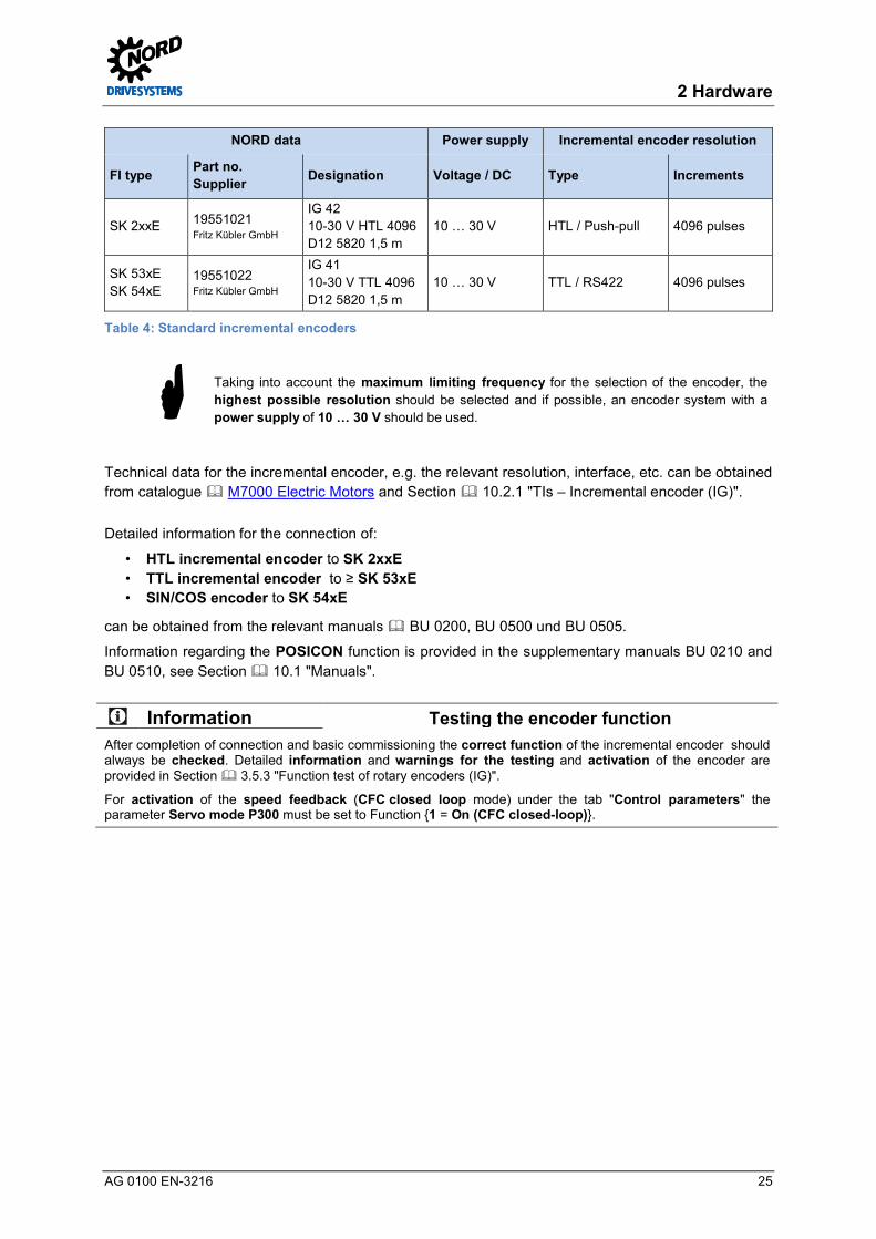
2 Hardware
AG 0100 EN-3216 25
NORD data Power supply Incremental encoder resolution
FI type Part no. Supplier Designation Voltage / DC Type Increments
SK 2xxE 19551021 Fritz Kübler GmbH
IG 42 10-30 V HTL 4096 D12 5820 1,5 m
10 … 30 V HTL / Push-pull 4096 pulses
SK 53xE SK 54xE
19551022 Fritz Kübler GmbH
IG 41 10-30 V TTL 4096 D12 5820 1,5 m
10 … 30 V TTL / RS422 4096 pulses
Table 4: Standard incremental encoders
Taking into account the maximum limiting frequency for the selection of the encoder, the highest possible resolution should be selected and if possible, an encoder system with a power supply of 10 … 30 V should be used.
Technical data for the incremental encoder, e.g. the relevant resolution, interface, etc. can be obtained from catalogue M7000 Electric Motors and Section 10.2.1 "TIs – Incremental encoder (IG)".
Detailed information for the connection of:
• HTL incremental encoder to SK 2xxE • TTL incremental encoder to ≥ SK 53xE • SIN/COS encoder to SK 54xE
can be obtained from the relevant manuals BU 0200, BU 0500 und BU 0505.
Information regarding the POSICON function is provided in the supplementary manuals BU 0210 and BU 0510, see Section 10.1 "Manuals".
Information Testing the encoder function After completion of connection and basic commissioning the correct function of the incremental encoder should always be checked. Detailed information and warnings for the testing and activation of the encoder are provided in Section 3.5.3 "Function test of rotary encoders (IG)".
For activation of the speed feedback (CFC closed loop mode) under the tab "Control parameters" the parameter Servo mode P300 must be set to Function 1 = On (CFC closed-loop). Pos: 68 /Appli kationen/[AG 0100 - AG 0101] allgemeingül tige M odule/2. H ardware/Auswahl Absol utwertdr ehg eber (AG) [Ü 2] @ 7\mod_1435051589005_388.docx @ 228469 @ 2 @ 1
Controller Optimisation – Guideline for AC motors - CFC Closed-Loop
26 AG 0100 EN-3216
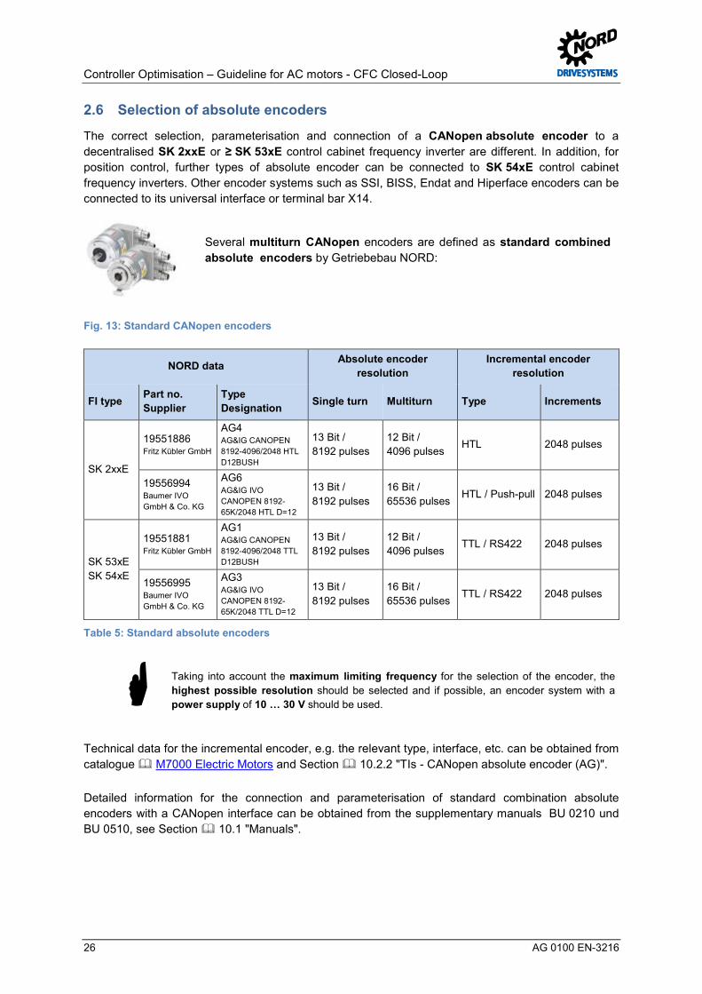
2.6 Selection of absolute encoders Pos: 69 /Appli kationen/[AG 0100 - AG 0101] allgemeingül tige M odule/2. H ardwareAuswahl Absolutwertdrehgeber (AG) @ 5\mod_1407413591878_388.docx @ 146662 @ @ 1
The correct selection, parameterisation and connection of a CANopen absolute encoder to a decentralised SK 2xxE or ≥ SK 53xE control cabinet frequency inverter are different. In addition, for position control, further types of absolute encoder can be connected to SK 54xE control cabinet frequency inverters. Other encoder systems such as SSI, BISS, Endat and Hiperface encoders can be connected to its universal interface or terminal bar X14.
Several multiturn CANopen encoders are defined as standard combined absolute encoders by Getriebebau NORD:
Fig. 13: Standard CANopen encoders
NORD data Absolute encoder resolution
Incremental encoder resolution
FI type Part no. Supplier
Type Designation Single turn Multiturn Type Increments
SK 2xxE
19551886 Fritz Kübler GmbH
AG4 AG&IG CANOPEN 8192-4096/2048 HTL D12BUSH
13 Bit / 8192 pulses
12 Bit / 4096 pulses
HTL 2048 pulses
19556994 Baumer IVO GmbH & Co. KG
AG6 AG&IG IVO CANOPEN 8192-65K/2048 HTL D=12
13 Bit / 8192 pulses
16 Bit / 65536 pulses
HTL / Push-pull 2048 pulses
SK 53xE SK 54xE
19551881 Fritz Kübler GmbH
AG1 AG&IG CANOPEN 8192-4096/2048 TTL D12BUSH
13 Bit / 8192 pulses
12 Bit / 4096 pulses
TTL / RS422 2048 pulses
19556995 Baumer IVO GmbH & Co. KG
AG3 AG&IG IVO CANOPEN 8192-65K/2048 TTL D=12
13 Bit / 8192 pulses
16 Bit / 65536 pulses
TTL / RS422 2048 pulses
Table 5: Standard absolute encoders
Taking into account the maximum limiting frequency for the selection of the encoder, the highest possible resolution should be selected and if possible, an encoder system with a power supply of 10 … 30 V should be used.
Technical data for the incremental encoder, e.g. the relevant type, interface, etc. can be obtained from catalogue M7000 Electric Motors and Section 10.2.2 "TIs - CANopen absolute encoder (AG)".
Detailed information for the connection and parameterisation of standard combination absolute encoders with a CANopen interface can be obtained from the supplementary manuals BU 0210 und BU 0510, see Section 10.1 "Manuals".
2 Hardware
AG 0100 EN-3216 27
NOTICE Installation of rotary encoders
It is essential that the combination absolute encoder (single and multiturn with integral incremental track) is mounted on the end of the motor shaft.
Other types of absolute encoder (e.g. Type AG1 / Part no. 19551881 / Kübler Type 8.5888.0421.2102. S010.K014) must not necessarily be mounted on the end of the motor shaft.
In this case, the speed ratio in the frequency inverter must be parameterised with the aid of the Ratio P607 and the Reduction Ratio P608. Otherwise, inaccuracy of the speed (incremental track) and / or the position control may result.
For an absolute encoder, the encoder system must be parameterised in the Parameter Travel measurement system P604, and the corresponding resolutions / pulse numbers and the encoder type (Single or Multiturn) must be parameterised in the parameter Absolute encoder P605.
For detailed information, please refer to the relevant manual for the frequency inverter, see 10.1 "Manuals" or Section 3.6.1 "Parameterisation of CANopen encoders (absolute encoders)".
Information Activating the position control For positioning / position control (CFC Closed Loop mode) the position control must be activated with the parameter Position control P600 or the required function (selection of ramp type) must be parameterised in the tab "Positioning parameters". For further details of activation of the position control, see 6.4.2 "Activating the position control". Pos: 75 /Appli kationen/[AG 0100 - AG 0101] allgemeingül tige M odule/3. Gr undi nbetriebnahme/Gr undinbetriebnahme [Ü 1] @ 7\mod_1431930880787_388.docx @ 219851 @ 1 @ 1

Controller Optimisation – Guideline for AC motors - CFC Closed-Loop
28 AG 0100 EN-3216
3 Basic Commissioning Pos: 76 /Appli kationen/[AG 0100 - AG 0102] allgemeingül tige M odule/Str uktur moduleSchrit t 2 @ 7\mod_1434978697929_388.docx @ 227692 @ @ 1
Step 2
Pos : 77 /Appli kationen/[AG 0100 - AG 0101] allgemeingül tige M odule/Str uktur module/Infor mation @ 7\mod_1434979005376_388.docx @ 227948 @ @ 1
Information
Pos : 78 /Appli kationen/[AG 0100] R egleropti mi erung ASM - CFC Cl osed- Loop/3. Grundi nbetri ebnahme/Grundi nbetri ebnahme @ 5\mod_1400509373683_388.docx @ 133040 @ @ 1
If the frequency inverter is not in the state as delivered, a reset of all parameters should generally be carried out via the parameter Factory Setting P523 before basic commissioning is carried out. This parameter can be found under the tab "Additional Parameters".
All parameters which are not explicitly mentioned in this guide should therefore be left in the factory or default setting. For more detailed information, please refer to the relevant manual for the frequency inverter, see 10.1 "Manuals".
Information Parameterisation Other application-specific settings, e.g. Deceleration time P103 (Brake reaction time P107 and Brake delay off P114) are not described in this guide and must be adjusted independently by the user! For optimisation of the controller only the Acceleration time P102, for the speed control, and the Deceleration time P103, need to be adjusted.
Some other parameters, e.g. Absolute mini. freq. P505 and the Flux delay P558, must be changed for the particular controller optimisation in order to obtain meaningful scope images.
After completion of the individual controller optimisations these parameters must be re-adjusted according to the particular requirements of the application.
Pos: 81 /Appli kationen/[AG 0100 - AG 0101] allgemeingül tige M odule/3. Gr undi nbetriebnahme/Betri ebsanzeig e Ei nstellungen [Ü2] @ 7\mod_1432016400233_388.docx @ 220639 @ 2 @ 1
3.1 Operating display settings Pos: 82 /Appli kationen/[AG 0100 - AG 0101] allgemeingül tige M odule/Str uktur module/H andl ungsanweisung @ 7\mod_1434979210308_388.docx @ 227979 @ @ 1
Instructions
Pos : 83 /Appli kationen/[AG 0100 - AG 0101] allgemeingül tige M odule/3. Gr undi nbetriebnahmeBetriebsanzeige Ei nstellungen @ 8\mod_1436185628917_388.docx @ 230906 @ @ 1
For optimisation of the relevant controller, the following two parameters must be checked or set in advance.
Parameter No. [-Array] Name [Unit] Factory
setting Setting
related to parameter set (P1, ... , P4)
OPERATING DISPLAYS
P001 Select of disp.value 0* 0 2 (Setpoint frequency [Hz])
P003 Supervisor-Code 1 ** 1 3 (all parameters visible) only for SK 2xxE
* 0 corresponds to the actual frequency [Hz]
** 1 corresponds to all parameters visible except P3xx / P6xx
In general, optimisation of the speed and position controllers should be made in dynamic operation under load conditions with specification of a setpoint. Because of this, the Select of disp.value P001 should be changed from the function 0 = Actual frequency to 2 = Setpoint frequency. The setpoint frequency is displayed in [Hz].

3 Basic Commissioning
AG 0100 EN-3216 29
In contrast, optimisation of the current controller should be made in static operation without load and without specification of a setpoint.
Information Supervisor-Code The tabs Control Parameters P3xx and Positioning P6xx are only enabled and therefore made visible for decentralised SK 2xxE frequency inverters by means of Supervisor-code P003 3 = all parameters visible. In the NORD CON display, all tabs are always visible.
For control cabinet SK 5xxE frequency inverters all tabs are enabled or displayed in the factory setting 1 = all parameters visible. Pos: 87 /Appli kationen/[AG 0100 - AG 0101] allgemeingül tige M odule/3. Gr undi nbetriebnahme/Motor daten [Ü2] @ 7\mod_1431951290559_388.docx @ 220373 @ 2 @ 1
3.2 Motor data Pos: 89 /Appli kationen/[AG 0100 - AG 0102] allgemeingül tige M odule/Str uktur module/Infor mation & H andl ungsanweisung @ 7\mod_1434981091960_388.docx @ 228011 @ @ 1
Information & instructions
Pos : 90 /Appli kationen/[AG 0100] R egleropti mi erung ASM - CFC Cl osed- Loop/3. Grundi nbetri ebnahme/M otordaten @ 5\mod_1400586645909_388.docx @ 133439 @ @ 1
The windings of an asynchronous motor (ASM) can be connected in 2 ways (Y / ) depending on the mains voltage. Depending on the circuit, the asynchronous motor can be operated with or without a frequency inverter on different mains connections (including 230 V, 50 Hz and 400 V, 50 Hz) and therefore usually has several different V/f characteristic curves.
Fig. 14: Example of motor type plate
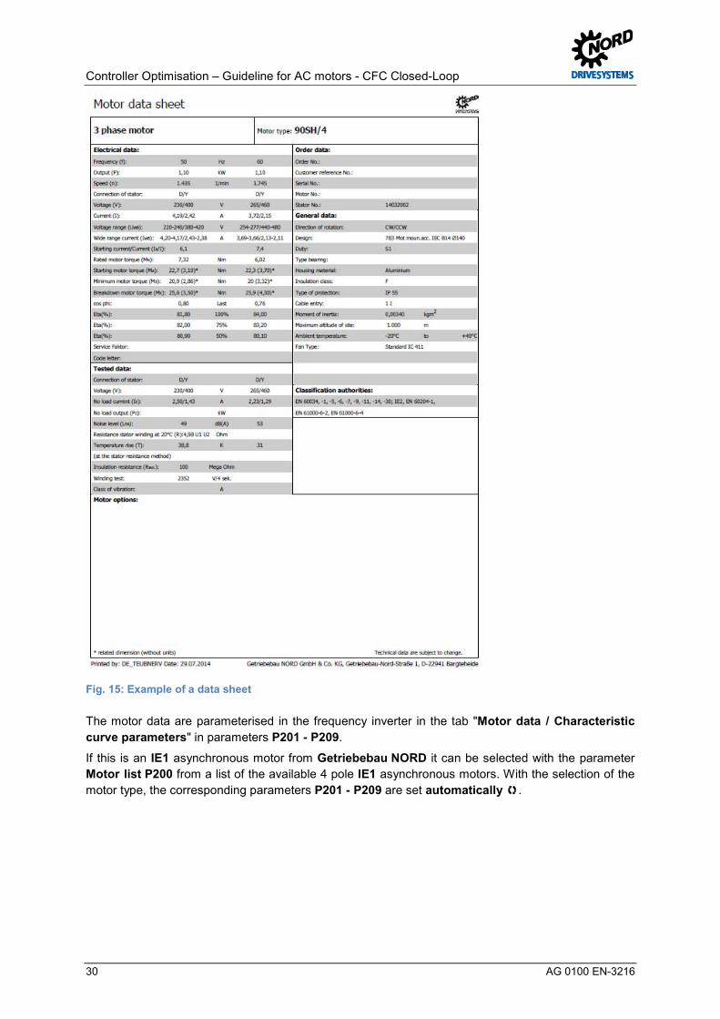
Controller Optimisation – Guideline for AC motors - CFC Closed-Loop
30 AG 0100 EN-3216
Fig. 15: Example of a data sheet
The motor data are parameterised in the frequency inverter in the tab "Motor data / Characteristic curve parameters" in parameters P201 - P209.
If this is an IE1 asynchronous motor from Getriebebau NORD it can be selected with the parameter Motor list P200 from a list of the available 4 pole IE1 asynchronous motors. With the selection of the motor type, the corresponding parameters P201 - P209 are set automatically .
3 Basic Commissioning
AG 0100 EN-3216 31
Information NORD motor data The motor data which are saved in the frequency inverter are only for IE1 asynchronous motors and IE4 synchronous motors manufactured by Getriebebau NORD. The values have been calculated from the specific data sheets for the motor or the details on the type plate.
If the motor is e.g. an IE2 asynchronous motor or an asynchronous motor from a different manufacturer, the motor data obtained from the type plate on the motor or from the manufacturer's data sheet can be used.
After entry of the motor data the No load current P209 is always calculated automatically (from the values Nominal current P203 and Motor cos phi P206).
Parameter No. [-Array] Name [Unit] Factory
setting Setting
related to parameter set (P1, ... , P4)
MOTOR DATA/ CHARACTERISTIC CURVE PARAMETERS NORD IE2 motor
P200 (P) Motor list 0 0 (leave as set), as IE2 motor
P201 (P) Nominal frequency [Hz] 50.0* 50.0
P202 (P) Nominal speed [rpm] 1445* 1445 1440
P203 (P) Nominal current [A] 8.3* 8.3 8.02
P204 (P) Nominal voltage [V] 400* 400 (leave as set)
P205 (P) Nominal power [kW] 4* 4 (leave as set)
P206 (P) Cos phi 0.8* 0.8 0.83
P207 (P) Star Delta con. 1* 1 (leave as set)1 (1 = delta)
P208 (P) Stator resistance [Ω] 3.44* 3.44 3.25 (measured)
P209 (P) No load current [A] 4.4* 4.4 (calculated)
P220 (P) Par.-identification 0 0 1 (Identification RS)
*) dependent on FI power or P200 / P220
The Stator resistance P208 should always be measured and set with the automatic stator resistance measurement and should then be checked, see Par.-identification P220 and the function 1 = Identification RS.
Information Stator resistance The measured value or the value to be entered for the Stator resistance P208 of a line (if this is available) should always be relative to an ambient temperature of approx. 20 °C. Pos: 96 /Appli kationen/[AG 0100] R egleropti mi erung ASM - CFC Cl osed- Loop/3. Grundi nbetri ebnahme/N ORD - M otoren M otortypenschild / D atenblatt @ 11\mod_1460377028402_388.docx @ 317149 @ 35 @ 1 In den Parametern P201 bis P0

Controller Optimisation – Guideline for AC motors - CFC Closed-Loop
32 AG 0100 EN-3216
7
3.2.1 NORD – Motor type plates / Data sheet The motor data can be obtained from the motor type plate, see 3.2 "Motor data" and / or the manufacturer's data sheet. The manufacturer's motor data should be parameterised accordingly in the tab "Motor data / Characteristic curve parameters".
NORD motors
In general only the motor data for IE1 asynchronous motors should be selected by means of the motor type via the parameter Motor list P200, e.g. function 34 = 4.0 kW 400 V.
Fig. 16: NORD motor (IE2) Data Sheet SK 112MH/4

3 Basic Commissioning
AG 0100 EN-3216 33
If a NORD motor is not selected with the aid of the parameter Motor list P200, the motor data must be parameterised according to the type plate or from the data sheet. Getriebebau NORD IE2 and IE3 asynchronous motors and third party motors must always be parameterised manually by the user.
Pos: 100 /Appli kati onen/[AG 0100] Regl eropti mier ung ASM - CFC Cl osed-Loop/3. Gr undi nbetriebnahme/Motor en-Identifi kation @ 7\mod_1431954275725_388.docx @ 220476 @ 35 @ 1
3.2.2 Motor identification If the motor data is not known, or no type plate is available, there is the possibility of automatically determining the necessary motor data using a motor identification.
However, to do this, the motor data for the parameters:
• Nominal frequency P201 • Nominal speed P202 approx. values, as this depends on the number of pole pairs (2 / 4) • Nominal voltage P204 • Nominal power P205 • Star Delta con. P207
must be known to the user and parameterised in the frequency inverter under the tab "Motor data / Characteristic curve parameters".
NOTICE IE2 Motor data
As a 4-pole IE2 asynchronous motor has been used in this guide, selection or the pre-setting of the motor data (P2xx) must not be made with function 34 = 4.0 kW, 400 V via the parameter Motor list P200!
Otherwise the calculation of the ASM model will be based on "incorrect" motor data values.
Par.-identification P220
With the parameter Par.-identification P220 there is the possibility of obtaining some of the motor data automatically from the frequency inverter. With many ASMs better drive characteristics are enabled or obtained with the measured motor values.
Information Parameter identification SK 5xxE With SK 5xxE frequency inverters, for the Par.-identification P220 the function 2 = Identification motor is only possible for frequency inverter / motor combinations ≤ 7.5 kW (for 400 V) or. ≤ 4.0 kW (for 230 V).
For SK 5xxE applications ≥ 11.0 kW the function 2 = identification motor is not approved.
For decentralised SK 2xxE frequency inverters thefunction 2 = identification motor is possible for the entire power range.
The Par.-identification P220 must be carried out when the motor is cold (15 °C ≥ TMotor ≤ 25 °C) .
The following two functions can be selected:
• Function 1 Identification RS :
For the Identification RS only the Stator resistance P208 is determined by multiple measurements.
• Function 2 identification motor:
With identification motor all of the other parameters (P202, P203, P206, P208, P209) for asynchronous motors are only determined when the motor is at a standstill.

Controller Optimisation – Guideline for AC motors - CFC Closed-Loop
34 AG 0100 EN-3216
Information Stator resistance value After the measurement is complete, the determined stator resistance value is entered or displayed automatically in the parameter Stator resistance P208 .
In case of "incorrect" resistance values, the setting for the “Star Delta con. P207” and the motor connection in the connection terminal box should be checked. Pos: 102 /Appli kati onen/[AG 0100 - AG 0101] allgemei ngültige Modul e/Str ukturmodul e/Infor mation @ 7\mod_1434979005376_388.docx @ 227948 @ @ 1
Information
Pos : 103 /Appli kati onen/[AG 0100] Regl eropti mier ung ASM - CFC Cl osed-Loop/3. Gr undi nbetriebnahme/Ersatzschaltbild @ 5\mod_1401791541294_388.docx @ 134751 @ 3 @ 1
3.2.3 Schematic circuit diagram In general, all of the data which are necessary for control are calculated from the details on the type plate ( 3.2 "Motor data"). The required data refer to the data in the schematic circuit diagram (SCD) for the ASM.
For the Par.-identification P220 calculation of the motor data is based on measurement signals for the SCD data.
To some extent, the data from the schematic circuit diagram (SCD) which are required for control depend on the temperature (motor and ambient temperature). A correction of the values at higher motor temperatures is made automatically by the controller. If the stator resistance is measured at higher ambient temperatures or only after longer operation of the motor "incorrect"starting values for the automatic temperature correction result.
Information Displayed measurement values If the motor data are determined with the Par.-identification P220 and Function 2 = identification motor it is then possible to display these values in NORD CON or with a ParameterBox.
In the "Operating Displays" tab the corresponding values form the schematic circuit diagram which are to be displayed after the frequency inverter is enabled can be selected under the parameter Select of disp.value P001.
On the other hand, values calculated from the type plate data and data from the schematic circuit diagram can not be displayed via selection from the Motor list P200. Pos: 105 /Appli kati onen/[AG 0100] Regl eropti mier ung ASM - CFC Cl osed-Loop/3. Gr undi nbetriebnahme/Schl upfkompensati on anpassen [Ü2] @ 7\mod_1431955233551_388.docx @ 220508 @ 2 @ 1

3 Basic Commissioning
AG 0100 EN-3216 35
3.3 Adjusting the slip compensation Pos: 106 /Appli kati onen/[AG 0100 - AG 0101] allgemei ngültige Modul e/Str ukturmodul e/H andlungsanweisung @ 7\mod_1434979210308_388.docx @ 227979 @ @ 1
Instructions
Pos : 107 /Appli kati onen/[AG 0100] Regl eropti mier ung ASM - CFC Cl osed-Loop/3. Gr undi nbetriebnahme/Schl upfkompensati on anpassen @ 5\mod_1400586799521_388.docx @ 133485 @ @ 1
In the ASM model which is used for pre-control. The stator frequency which is required for a particular speed is determined with an equation. The precision of this depends on the rotor time constant tR.
The rotor time constant tR greatly depends on the temperature. If this is inaccurately tracked in the ASM model due to temperature drift, errors in the "pre-controlled" stator frequency result.
This effect can be compensated for with the Slip compensation P212. The slip compensation therefore improves the pre-control of the motor model.
Information Slip compensation P212 The 100 % factor setting should initially be reduced in advance to a guide value of 80 % for asynchronous motors.
After completion of the controller optimisation the motor can be operated at the operating point or in nominal load operation and the Slip compensation P212 can then be optimised
Parameter No. [-Array] Name [Unit] Factory
setting Setting
related to parameter set (P1, ... , P4)
MOTOR DATA/ CHARACTERISTIC CURVE PARAMETERS
P212 (P) Slip compensation [%] 100 100 → 80
The optimisation or correct setting of the slip compensation P212 is described in detail in Section 7.3 "Slip compensation". Pos: 109 /Appli kati onen/[AG 0100 - AG 0101] allgemei ngültige Modul e/3. Grundinbetriebnahme/Opti mier ung M otordaten [Ü 2] @ 7\mod_1431955832864_388.docx @ 220539 @ 2 @ 1
3.4 Optimisation of motor data Pos: 110 /Appli kati onen/[AG 0100 - AG 0101] allgemei ngültige Modul e/Str ukturmodul e/H andlungsanweisung @ 7\mod_1434979210308_388.docx @ 227979 @ @ 1
Instructions
Pos : 112 /Appli kati onen/[AG 0100] Regl eropti mier ung ASM - CFC Cl osed-Loop/3. Gr undi nbetriebnahme/NORD - Motor en @ 11\mod_1460367594281_388.docx @ 316894 @ 3 @ 1 In den Parametern P201 bis P07
3.4.1 NORD motors The motor data are only implemented in the motor list of the system software of the two frequency inverter series SK 2xxE and SK 5xxE for Getriebebau NORD IE1 asynchronous motors, see Parameter Motor list P200.
Optimisation of the specific motor data for Getriebebau NORD IE1, IE2 and IE3 asynchronous motors is only necessary, or must be carried out by the user in exceptional cases. In general, this applies for all NORD motors (e.g. field test drive units, special versions, etc.), which are not included in the Motor list P200.
For special applications, special motors and in case of application problems, we recommend that you contact the Service department of Getriebebau NORD. Pos: 117 /Appli kati onen/[AG 0100 - AG 0101] allgemei ngültige Modul e/3. Grundinbetriebnahme/Inkr emental drehgeber (IG) [Ü 2] @ 7\mod_1432014870412_388.docx @ 220608 @ 2 @ 1

Controller Optimisation – Guideline for AC motors - CFC Closed-Loop
36 AG 0100 EN-3216
3.5 Incremental encoder (IG) Pos: 118 /Appli kati onen/[AG 0100 - AG 0101] allgemei ngültige Modul e/Str ukturmodul e/Schrit t 3 @ 7\mod_1434978694045_388.docx @ 227660 @ @ 1
Step 3
Pos : 119 /Appli kati onen/[AG 0100 - AG 0101] allgemei ngültige Modul e/Str ukturmodul e/Infor mation & H andlungsanweisung @ 7\mod_1434981091960_388.docx @ 228011 @ @ 1
Information & instructions
Pos : 120 /Appli kati onen/[AG 0100 - AG 0101] allgemei ngültige Modul e/3. GrundinbetriebnahmeInkr ementaldr ehg eber (IG) @ 5\mod_1401801238324_388.docx @ 134871 @ @ 1
For the speed feedback, incremental encoders (IG) are usually used, which convert the rotary movement into electrical signals (TTL or HTL). Incremental encoders both with and without zero tracks can be used.
Three different encoder resolutions (1024, 2048 and 4096) are available as standard Getriebebau NORD encoders. As the default rotary encoder, a resolution of 4096 pulses (pulses/rotation) is pre-set at the factory in the frequency inverter. Technical data for the incremental encoder, e.g. the relevant connections can be obtained from catalogue M7000 Electric Motors.
NOTICE Installation of rotary encoders
The incremental encoder must be mounted on the end of the motor shaft. Otherwise, inaccuracy of the speed and / or the position control may result. Pos: 121 /Appli kati onen/[AG 0100 - AG 0101] allgemei ngültige Modul e/Str ukturmodul e/H andlungsanweisung @ 7\mod_1434979210308_388.docx @ 227979 @ @ 1
Instructions
Pos : 122 /Appli kati onen/[AG 0100 - AG 0101] allgemei ngültige Modul e/3. GrundinbetriebnahmePar ametrierung Drehgeber (IG) @ 5\mod_1400586722895_388.docx @ 133462 @ 35 @ 1
3.5.1 Parameterisation of encoders (IG) For connection of the incremental encoder to the control terminals of decentralised SK 2xxE frequency inverters, adjustment of the parameterisation of the digital inputs DIN2 and DIN3 is required via the parameters digit inputs P420 [-02] and [-03]. The connection of an IG with a zero track via DIN1 must be parameterised via the parameter Digital inputs P420 [-01], for further details see 3.5.2 "Encoder connection (IG)".
For control in CFC Closed-Loop mode (servo mode) it is essential that speed control with speed measurement is enabled via an incremental encoder (IG). In the "Control parameters" tab, the parameter Servo mode P300 with the function 1 = On (CFC Closed-Loop) is available for this.
Information Enabling of control parameters For decentralised SK 2xxE frequency inverters, the Control parameters P3xx tab is enabled with the parameter P003 Supervisor-Code 3 = all parameters visible
For the control cabinet frequency inverters SK 53xE and SK 54xE the tab is enabled as the default in the factory settings.
The corresponding pulse number / resolution for the encoder system must be parameterised in the parameter Incremental encoder P301, taking the appropriate prefix (note the installation position) into account.
Parameter No. [-Array] Name [Unit] Factory
setting Setting
related to parameter set (P1, ... , P4)
Speed control
P300 (P) Servo mode 0 (Off = VFC Open-Loop)
Refer to 3.5.5 "Activating the speed control"
P301 Incremental encoder 6* 6 5 (2048 pulses)
* 6 corresponds to 4096 pulses

3 Basic Commissioning
AG 0100 EN-3216 37
Incremental encoder (IG) with zero track
For applications with an incremental encoder with a zero track, the offset between the zero pulse and the actual rotor position "0" must be set manually in the parameter Encoder offset PMSM P334.
Parameter No. [-Array] Name [Unit] Factory
setting Setting
related to parameter set (P1, ... , P4)
Speed control
P334 (S) Encoder offset PMSM [rev] 0.000 0 0.491 *
P335 ** Sync. 0-pulse ** 0 See 3.5.4 "Incremental encoder (IG) with zero track"
*For the value, see on the label in the motor terminal box
* Parameter P335 Sync. 0-pulse encoders are only available for SK 54xE
Details of the parameters Encoder offset PMSM P334 and Sync. 0-pulse P335 can be obtained from Section 10.1 "Manuals". Pos: 124 /Appli kati onen/[AG 0100 - AG 0101] allgemei ngültige Modul e/3. GrundinbetriebnahmeAnschl uss Dr ehg eber (IG) @ 5\mod_1401101666318_388.docx @ 134054 @ 355 @ 1

Controller Optimisation – Guideline for AC motors - CFC Closed-Loop
38 AG 0100 EN-3216
3.5.2 Encoder connection (IG) Connection of the incremental encoder to the control terminals of the frequency inverter is different for the two frequency inverter series SK 2xxE and SK 5xxE and requires appropriately modified parameterisation. The connection of an incremental encoder with a zero track is also different for the two frequency inverters.
SK 2xxE
For decentralised SK 2xxE frequency inverters, connection of the incremental encoder (HTL) is made exclusively via the two digital inputs DIN2 (Terminal 22) and DIN3 (Terminal 23). In the "Control terminals" tab in parameter Digital inputs P420 [-02] and [-03] these must be switched to the function 0 = No function.
Parameter No. [-Array] Name [Unit] Factory
setting Setting
related to parameter set (P1, ... , P4)
CONTROL TERMINALS
P420 [-01] Digital inputs (DIN1) 1 1 → 43 (only for IG with zero track)
P420 [-02] Digital inputs (DIN2) 2 2 → 0
P420 [-03] Digital inputs (DIN3) 4 4 → 0
If the incremental encoder is connected and the Digital inputs DIN2 and DIN3 are not parameterised to the function 0 = No function there will be a "clicking" noise when the drive unit is enabled!
Connection of incremental encoders with a zero trackmay only be made to Digital input 1 (DIN1). Only the signal + zero track is connected to Terminal 21 (DIN1).
In the parameter Digital inputs P420 [-01], by selecting the function 43 = 0-track HTL encoder DI1, the starting behaviour of the synchronisation of the rotor position is specified.
SK 520E to SK 535E
Connection of the incremental encoder (TTL) for control cabinet frequency inverters of performance levels ≥ SK 520E is made via the terminal bar X6 (Terminals 51 … 54).
Connection of incremental encoders with a zero track is only made to the Universal encoder interface, terminal bar X14, terminals 63 (Signal CLK-) and 64 (Signal CLK+) in the case of SK 540E and SK 545E control cabinet frequency inverters.
Information Power supply Encoder systems with a suitable power supply (10 V to 30 V) should be planned and used.
The technical data can be obtained from catalogue M7000 Electric Motors or from the data sheets 10.2.1 "TIs – Incremental encoder (IG)". Pos: 126 /Appli kati onen/[AG 0100 - AG 0101] allgemei ngültige Modul e/3. GrundinbetriebnahmeFunktionsprüfung Drehgeber (IG) @ 5\mod_1401101670698_388.docx @ 134078 @ 3 @ 1

3 Basic Commissioning
AG 0100 EN-3216 39
3.5.3 Function test of rotary encoders (IG) After completion of connection and basic commissioning the correct function of the incremental encoder (IG) should always be checked.
The prefix (+ or - pulse numbers) depends on the installation position of the incremental encoder on the motor shaft. For example, if the direction of rotation of the IG does not correspond to the direction of rotation of the frequency inverter (recommended specification: positive values = clockwise rotation) a negative pulse number must be set in the Incremental encoder P301.
Information Checking the encoder speed To check the correct selection of the Incremental encoder P301 the parameter Speed encoder P735 is available in the "Information Parameters" tab.
For the function test of the parameterised encoder function, the motor can be enabled e.g. with a setpoint of 10 Hz depending on the Nominal frequency P201, e.g. 50 Hz or 70 Hz in clockwise rotation. With this, for a 4-pole motor the parameter Speed encoder P735 should have a value of approx. 300 rpm.
However, the value for the Speed encoder P735 may vary according to the application, as the setting for the Maximum frequency P105 parameter and the selected setpoint source must also be taken into account.
Parameter No. [-Array] Name [Unit] Factory
setting Setting
related to parameter set (P1, ... , P4)
INFORMATION, read only
P735 Speed encoder approx. 300 rpm Pos: 127 /Appli kati onen/[AG 0100 - AG 0101] allgemei ngültige Modul e/3. GrundinbetriebnahmeInkr ementaldr ehg eber (IG) mit N ullspur @ 6\mod_1430815306720_388.docx @ 215070 @ 35 @ 1 In den Parametern P201 bis P07
3.5.4 Incremental encoder (IG) with zero track With the SK 54xE, the zero track of an incremental encoder is only evaluated if no universal encoder is connected to the universal encoder interface, terminal bar X14. Refer to 3.5.2 "Encoder connection (IG)" for further details.
The zero track of an incremental encoder can be used to determine either the
• Zero rotor position of the synchronous motor or the PMSM
The parameter Regulation PMSM P330 must be set to either the function • 0 = Voltage-controlled or • 1 = Test signal method if an incremental encoder is used..
For IE4 synchronous motors manufactured by Getriebebau NORD, the encoder offset between the d-axis of the rotor and the zero pulse is measured and documented with a "rpm" and "°" label in the terminal box. For further details, refer to P334 Encoder offset PMSM 3.5.1 "Parameterisation of encoders (IG)".
or for the synchronisation of the
• Zero point (reference point) of the incremental encoder.
The following parameters are available for synchronisation of the zero pulse of the incremental encoder.

Controller Optimisation – Guideline for AC motors - CFC Closed-Loop
40 AG 0100 EN-3216
Sync. 0-pulse P335
Various functions can be selected for synchronisation:
• Function 0 = Sync. off
Synchronisation is disabled or switched off and corresponds to the factory setting.
• Function 1 = Sync rotor pos. PMSM
Synchronisation of the rotor position of a PMSM, i.e. a synchronous motor is enabled or switched on.
• Function 2 = Sync. reference pos.
Synchronisation of the reference point for positioning applications (POSICON) is enabled or switched on.
• Function 3 = Sync. PMSM + pos.
Both the synchronisation of the rotor position of a PMSM / synchronous motor as well as the reference point for positioning applications (POSICON) is enabled or switched on.
Pos: 128 /Appli kati onen/[AG 0100 - AG 0101] allgemei ngültige Modul e/3. GrundinbetriebnahmeDr ehzahlregel ung akti vi eren @ 5\mod_1401801846691_388.docx @ 134894 @ 3 @ 1
3.5.5 Activating the speed control For activation of the speed feedback (CFC Closed-Loop mode), under the tab "Control parameters" the parameter Servo mode P300 must be set to Function 1 = On (CFC Closed-Loop).
CAUTION Servo mode activation
This setting should only be made after the check of the direction of rotation of the incremental encoder has been successfully completed.
Otherwise, unexpected movements (wrong direction of rotation) may result. This may cause both material damage as well as injuries to persons
Parameter No. [-Array] Name [Unit] Factory
setting Setting
related to parameter set (P1, ... , P4)
Speed control
P300 (P) Servo mode 0 (Off = VFC Open-Loop) 0 → 1 (On = CFC Closed-Loop)
Pos: 129 /Appli kati onen/[AG 0100 - AG 0101] allgemei ngültige Modul e/3. Grundinbetriebnahme/Absol utwertdrehgeber ( AG) [Ü2] @ 7\mod_1432019892090_388.docx @ 220841 @ 2 @ 1

3 Basic Commissioning
AG 0100 EN-3216 41
3.6 Absolute encoder (AG)
Pos : 130 /Appli kati onen/[AG 0100 - AG 0101] allgemei ngültige Modul e/Str ukturmodul e/Infor mation & H andlungsanweisung @ 7\mod_1434981091960_388.docx @ 228011 @ @ 1
Information & instructions
Pos : 131 /Appli kati onen/[AG 0100 - AG 0101] allgemei ngültige Modul e/3. Grundinbetriebnahme/Absol utwertdrehgeber ( AG) @ 7\mod_1435066504466_388.docx @ 228500 @ @ 1
For the speed feedback a combined absolute encoder (AG) with a separate incremental track (IG track) which as a measurement sensor converts the rotary movement into electrical signals (TTL or HTL) can also be used. Both CANopen absolute encoders, as well as various universal encoders can be used.
Four different encoder types with 13 Bit single turn resolution (8192) as well as 12 Bit (4096) or 16 Bit (65536) multiturn resolution are available as standard Getriebebau NORD encoders. A pulse number of 2048 (pulses/rotation) is used as the standard resolution of the incremental track and is pre-set at the factory in the frequency encoder. Technical data CANopen absolute encoders, e.g. the relevant connections can be obtained from catalogue M7000 Electric Motors.
NOTICE Installation of rotary encoders
It is essential that the combination absolute encoder (single and multiturn with integral incremental track) is mounted on the end of the motor shaft.
Other types of absolute encoder (e.g. Type AG1 / Part no. 19551881 / Kübler Type 8.5888.0421.2102. S010.K014) must not necessarily be mounted on the end of the motor shaft.
In this case, the speed ratio in the frequency inverter must be parameterised with the aid of the Ratio P607 and the Reduction Ratio P608. Otherwise, inaccuracy of the speed (incremental track) and / or the position control may result. Pos: 132 /Appli kati onen/[AG 0100 - AG 0101] allgemei ngültige Modul e/Str ukturmodul e/H andlungsanweisung @ 7\mod_1434979210308_388.docx @ 227979 @ @ 1
Instructions
Pos : 133 /Appli kati onen/[AG 0100 - AG 0101] allgemei ngültige Modul e/3. GrundinbetriebnahmePar ameterier ung CAN open Drehgeber (AG) @ 5\mod_1407847143029_388.docx @ 146952 @ 3 @ 1
3.6.1 Parameterisation of CANopen encoders (absolute encoders) For control in CFC closed loop mode (servo mode), for a CANopen standard combined absolute encoder (AG) with an additional incremental track (IG) it is essential that the speed control with speed measurement is enabled. In the "Control parameters" tab, the parameter Servo mode P300 with the function 1 = On (CFC Closed-Loop) is available for this.
For an encoder system with incremental signals, the corresponding pulse number / resolution must be parameterised in the parameter Incremental encoder P301, taking the appropriate prefix (note the installation position) into account.
Parameter No. [-Array] Name [Unit] Factory
setting Setting
related to parameter set (P1, ... , P4)
Speed control
P300 (P) Servo mode 0 (Off = VFC Open-Loop) 0 → 1 (On = CFC Closed-Loop)
P301 Incremental encoder 6* 6 → 5 (2048 pulses)
* 6 corresponds to 4096 pulses
For the position detection of the position controller with a standard combination encoder with a CANopen interface (see Section 2.6 "Selection of absolute encoders"), several parameters must be set under the "Positioning" tab for position detection by the position controller.
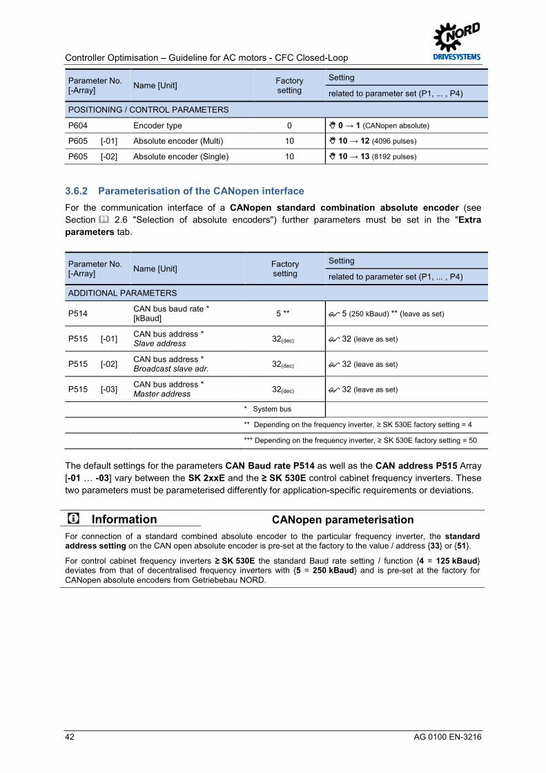
Controller Optimisation – Guideline for AC motors - CFC Closed-Loop
42 AG 0100 EN-3216
Parameter No. [-Array] Name [Unit] Factory
setting Setting
related to parameter set (P1, ... , P4)
POSITIONING / CONTROL PARAMETERS
P604 Encoder type 0 0 → 1 (CANopen absolute)
P605 [-01] Absolute encoder (Multi) 10 10 → 12 (4096 pulses)
P605 [-02] Absolute encoder (Single) 10 10 → 13 (8192 pulses) Pos: 134 /Appli kati onen/[AG 0100 - AG 0101] allgemei ngültige Modul e/3. GrundinbetriebnahmePar ameterier ung CAN open Schnittstelle ( AG) @ 5\mod_1409566412946_388.docx @ 148784 @ 3 @ 1
3.6.2 Parameterisation of the CANopen interface For the communication interface of a CANopen standard combination absolute encoder (see Section 2.6 "Selection of absolute encoders") further parameters must be set in the "Extra parameters tab.
Parameter No. [-Array] Name [Unit] Factory
setting Setting
related to parameter set (P1, ... , P4)
ADDITIONAL PARAMETERS
P514 CAN bus baud rate * [kBaud] 5 ** 5 (250 kBaud) ** (leave as set)
P515 [-01] CAN bus address * Slave address 32(dec) 32 (leave as set)
P515 [-02] CAN bus address * Broadcast slave adr. 32(dec) 32 (leave as set)
P515 [-03] CAN bus address * Master address 32(dec) 32 (leave as set)
* System bus
** Depending on the frequency inverter, ≥ SK 530E factory setting = 4
*** Depending on the frequency inverter, ≥ SK 530E factory setting = 50
The default settings for the parameters CAN Baud rate P514 as well as the CAN address P515 Array [-01 … -03] vary between the SK 2xxE and the ≥ SK 530E control cabinet frequency inverters. These two parameters must be parameterised differently for application-specific requirements or deviations.
Information CANopen parameterisation For connection of a standard combined absolute encoder to the particular frequency inverter, the standard address setting on the CAN open absolute encoder is pre-set at the factory to the value / address 33 or 51.
For control cabinet frequency inverters ≥ SK 530E the standard Baud rate setting / function 4 = 125 kBaud deviates from that of decentralised frequency inverters with 5 = 250 kBaud and is pre-set at the factory for CANopen absolute encoders from Getriebebau NORD. Pos: 135 /Appli kati onen/[AG 0100 - AG 0101] allgemei ngültige Modul e/3. GrundinbetriebnahmeAnschl uss C AN open Drehgeber (AG) @ 5\mod_1407846646103_388.docx @ 146898 @ 355 @ 1

3 Basic Commissioning
AG 0100 EN-3216 43
3.6.3 Connection of CANopen encoders (absolute encoder) The connection and the necessary 24 V power supply of the CANopen absolute encoders is different for the frequency inverter series SK 2xxE and SK 5xxE.
SK 2xxE
Direct connection to the relevant bus option with system bus interface to the terminals:
Terminal Designation Function Information
44 VO / 24 V 24 V supply 40 GND / 0 V 0 V supply 77 SYS H System bus + SYS H / (CAN High) 78 SYS L System bus - SYS l / (CAN Low) Shield via large-area earthing using the EMC cable connector
Table 6: SK 2xxE interface connection to the system bus
For detailed information regarding the connection of a CANopen absolute encoder to an SK 2xxE please refer to the supplementary manual BU 0210 and the manual BU 0200, see Section 10.1 "Manuals".
SK 53xE and SK 54xE
An optional RJ45 WAGO connection module (Part No. 278910300) is available for connection of the external power supply of the CANopen absolute encoder of SK 53xE and SK 54xE for frequency encoder applications.
Detailed information for the connection of a CANopen absolute encoder to a frequency inverter ≥ SK 530E and to the RJ45 WAGO connection manual can be obtained from the supplementary manual BU 0510 and the manuals BU 0500 or BU 0505, see Section 10.1 "Manuals".
Fig. 17: RJ45 WAGO connection module Pos: 136 /Appli kati onen/[AG 0100 - AG 0101] allgemei ngültige Modul e/3. GrundinbetriebnahmeFunktionsprüfung CAN open Dr ehg eber (AG) @ 5\mod_1407847234061_388.docx @ 146976 @ 35 @ 1

Controller Optimisation – Guideline for AC motors - CFC Closed-Loop
44 AG 0100 EN-3216
3.6.4 Function test of CANopen encoders (absolute encoders) After completion of connection and basic commissioning the correct function of the CANopen absolute encoder (AG) should always be checked.
Information CANopen status The CANopen status of the absolute encoder interface and the frequency inverter can be evaluated or checked with the parameter CANopen status P748 under the tab "Information Parameters".
Further CANopen participants (nodes / addresses) may possibly be connected to the CANopen field bus, so that the assignment of double addresses or different Baud rates etc. may have been parameterised.
Parameter No. [-Array] Name [Unit] Factory
setting Setting
related to parameter set (P1, ... , P4)
INFORMATION, read only
P748 [-01] CANopen status * [hex] Check display of CANopen status
* System bus
The parameter CANopen state P748 shows the status of the CANbus /CANopen in bit-coded form, i.e. therefore the state of CANopen MNT For detailed information, please refer to the relevant manual for the frequency inverter, see 10.1 "Manuals".
Procedure
For both the function test of the CANopen encoder as well as for commissioning of the position control, it is recommended that a set procedure is followed.
CAUTION Servo mode activation
Ensure that the Emergency Stop and safety circuits are functional! For lifting gear applications, prior to switching on for the first time measures must be taken to prevent the load from falling. In addition, for the load take-up, the parameters Brake reaction time P107 and Brake delay off P114 should be optimised after the optimisation of the speed controller.
Otherwise, unexpected movements (wrong direction of rotation) may result. This may cause both material damage as well as injuries to persons
1 Commission the axis without position control
After the input of all parameters the drive unit should first be commissioned without control of the position or speed. For this the speed control must be switched off in the parameter Servo mode P300 with the function 0 = Off (VFC Open-Loop) and the parameter Position control P600 and the function 0 = Off.
2 Commissioning the speed controller
This step may be omitted if no speed control is required or if an incremental encoder is used. Otherwise the Servo mode P300 should be switched to 1 = On (CFC Closed-Loop)

3 Basic Commissioning
AG 0100 EN-3216 45
Information Servo mode If the motor only runs at a slow speed with a high current consumption after activation of the Servo mode P300 with the function 1 = On (CFC Closed-Loop), there is usually an error in the wiring or the parameterisation of the incremental encoder connection. The most frequent cause is an incorrect assignment of the direction of rotation of the motor to the counting direction of the encoder.
The optimisation of the speed control is optimised after commissioning of the position control, as the behaviour of the position control circuit can be influenced by changes to the speed control parameters.
3 Commissioning the position controller
After setting parameter Encoder type P604 and Absolute encoder P605 it must be checked whether the actual position is correctly detected. The actual position is displayed in the parameter actual position P601. The value must be stable and become larger if the motor is switched on with rotation to the right enabled. If the value does not change when the axis is moved, the parameterisation and the encoder connection must be checked. The same applies if the displayed value for the actual position jumps although the axis has not moved.
4 Specify and move to the setpoint position
After this a setpoint position in the vicinity of the actual position should be specified and moved to by enabling the drive unit.
Information Testing the absolute encoder function The encoder position of the absolute encoder can be checked with the parameter Actual position P601 using NORD CON. If the direction of action of the absolute encoder is not correct, i.e. after being enabled, the axis moves away from the setpoint position instead of towards it, this indicates an incorrect assignment between the direction of rotation of the motor and the direction of rotation of the encoder. In this case, there is the possibility of changing this by a negative input of the speed ratio value in the parameter Ratio P607.
Under the "Positioning Parameters" tab, using the parameter Encoder type P604, the corresponding encoder system is parameterised for detection of the actual position value.
The direction of effect of the absolute encoder, i.e. the prefix (+ or - pulse numbers) depends on the installation position of the incremental encoder on the motor shaft. For example, if the direction of rotation of the incremental encoder does not correspond to the direction of rotation of the frequency inverter (recommended specification: positive values = clockwise rotation) a negative pulse number must be set in the Incremental encoder P301.
Parameter No. [-Array] Name [Unit] Factory
setting Setting
related to parameter set (P1, ... , P4)
POSITIONING / CONTROL PARAMETERS
P601 actual position [rev] --- Check display
P602 Actual Ref. Pos. [rev] --- Check display
P603 Curr. position diff. [rev] --- Check display
P604 Encoder type 0 0 1 (CANopen absolute)
P607 [-02] Ratio (absolute encoder) 1
P608 [-02] Reduction Ratio (absolute encoder) 1
If the function test is complete and the detection of the actual position operates correctly, the position controller can be optimised according to the following procedure, see 6 "Position control". Pos: 142 /Appli kati onen/[AG 0100 - AG 0101] allgemei ngültige Modul e/4. Str omregel ung/Str omregel ung [Ü1] @ 7\mod_1431930921610_388.docx @ 219882 @ 1 @ 1

Controller Optimisation – Guideline for AC motors - CFC Closed-Loop
46 AG 0100 EN-3216
4 Current control Pos: 144 /Appli kati onen/[AG 0100 - AG 0101] allgemei ngültige Modul e/Str ukturmodul e/Schrit t 4 @ 7\mod_1434978702419_388.docx @ 227724 @ @ 1
Step 4
Pos : 145 /Appli kati onen/[AG 0100 - AG 0101] allgemei ngültige Modul e/Str ukturmodul e/Infor mation @ 7\mod_1434979005376_388.docx @ 227948 @ @ 1
Information
Pos : 146 /Appli kati onen/[AG 0100 - AG 0101] allgemei ngültige Modul e/4. Str omregel ungStromr egel ung @ 5\mod_1400587108784_388.docx @ 133577 @ 5 @ 1
The current control is comprised of two different PI controllers:
• Torque current controller (P312, P313, P314) • Field current controller (P315, P316, P317)
These are divided into parameters P312 / P315 for the P component and parameters P313 / P316 for an I component. In addition, two further "limit parameters" P314 or P317 complete the particular controller. These are used to limit the maximum voltage range ( 10.1 "Manuals").
Information Controller values The settings for the P component and the I component of the particular controller should always have the same setting, i.e. P312 = P315 and P313 = P316. The limit parameters P314 or P317 are not considered in further detail in this guide!
The following diagrams show several control curves / transient responses which occur after a sudden change of the setpoint for various PI controllers.
Diagram 1
Selected P component too small
Diagram 2
P component optimised and I component selected too small
Diagram 3
P and I component optimal
Diagram 4
P component optimised and I component selected too large
Fig. 18: Control value curves

4 Current control
AG 0100 EN-3216 47
The various control curves, where the setpoint is shown in RED and the actual value is shown in GREEN, describe the dynamic curve for the transient response, which is set via the individual control parameters (P and I component) of the controller.
It is recommended that the following optimisation steps are performed to systematically adjust a current controller.
Overview of the optimisation procedure
• Set the I component to a low value
• Increase the P component from the standard value in e.g. 50 % increments until no further rapid increase of the actual value (Flux current ~P721) can be achieved. A curve as shown in Diagram 2 results.
• This is followed by an increase of the I component in e.g. 20 % / ms increments until an overshoot of approx. 3 to 5 % is achieved. Diagram 3 shows the optimised curve, whereby in this diagram, the overshoot is slightly exaggerated for clarity.
Diagram 1 shows the curve if the P components is selected too small. In contrast Diagram 4 shows the curve for the actual value when the I component is set too large. In this case, the I component should be gradually reduced to set a curve as shown in Diagram 3.
The aim is to optimise the curve for the Flux current ~P721 with the "correct" settings of the P and I components. The practical implementation for optimisation of a current controller is described in Section 4.4 "Optimisation procedure".
Pos: 151 /Appli kati onen/[AG 0100 - AG 0101] allgemei ngültige Modul e/Allgemei n gül tige Ü berschriften/Wei ter e Ei nstellungen [Ü2] @ 7\mod_1432029630965_388.docx @ 220873 @ 2 @ 1
4.1 Further settings Pos: 153 /Appli kati onen/[AG 0100 - AG 0101] allgemei ngültige Modul e/Str ukturmodul e/H andlungsanweisung @ 7\mod_1434979210308_388.docx @ 227979 @ @ 1
Instructions
Pos : 154 /Appli kati onen/[AG 0100] Regl eropti mier ung ASM - CFC Cl osed-Loop/4. Stromr egelung/Wei ter e Ei nstellungen @ 5\mod_1401720469456_388.docx @ 134695 @ @ 1
For optimisation of the current controller, it is essential that the following parameters are set in advance.
Parameter No. [-Array] Name [Unit] Factory
setting Setting
related to parameter set (P1, ... , P4)
ADDITIONAL PARAMETERS
P505 (P) Absolute mini. freq. [Hz] 2.0 2.0 → 0.0
P558 (P) Flux delay [ms] 1 1 → 0
Before starting the scope recording and enabling the drive unit, the setpoint must always be set to 0 % (0 Hz).
Pos: 157 /Appli kati onen/[AG 0100 - AG 0101] allgemei ngültige Modul e/Allgemei n gül tige Ü berschriften/NORD CON [Ü 2] @ 7\mod_1432029689942_388.docx @ 220904 @ 2 @ 1

Controller Optimisation – Guideline for AC motors - CFC Closed-Loop
48 AG 0100 EN-3216
4.2 NORD CON Pos: 158 /Appli kati onen/[AG 0100 - AG 0101] allgemei ngültige Modul e/Str ukturmodul e/Infor mation & H andlungsanweisung @ 7\mod_1434981091960_388.docx @ 228011 @ @ 1
Information & instructions
Pos : 159 /Appli kati onen/[AG 0100] Regl eropti mier ung/4. Str omregel ung/N ORD C ON @ 5\mod_1403614271863_388.docx @ 137968 @ @ 1
NORD CON should be used for programming, operation and optimisation of the controllers. Optimisation of the controllers for NORD frequency inverters can be performed with this parameterisation and control software. The oscilloscope function provides e.g the possibility to assess the particular optimisation steps on the basis of several scope recordings. Further information about the latest version can be found under the following link: NORD CON The functions Remote Control and Control as well as the Device Overview are available for control of the frequency inverter.
Fig. 19: NORD CON
Detailed information about the various functions, e.g. interface configuration, operation, oscilloscope settings, etc. can be found in the NORD CON Manual BU 0000, see 10.1 "Manuals". Pos: 160 /Appli kati onen/[AG 0100 - AG 0101] allgemei ngültige Modul e/4. Str omregel ungFernbedi enen @ 5\mod_1403610553540_388.docx @ 137894 @ 3 @ 1
4.2.1 Remote control The following setting must be made in the Remote Control screen to optimise the current controller before starting the scope recordings.
Leave the setpoint at 0 %, i.e. leave the setpoint frequency at 0 Hz
Alternative display possibility
Press the Enable button
Fig. 20: Remote control of the current controller, setpoint and enabling

4 Current control
AG 0100 EN-3216 49
New display in NORD CON
Fig. 21: Remote control of the current controller, setpoint and enabling
Information Remote Control display The display in the Remote Control screen may vary for different NORD CON settings and versions. E.g. the Remote Control screen is displayed differently for SK 5xxE frequency inverters. Pos: 162 /Appli kati onen/[AG 0100 - AG 0101] allgemei ngültige Modul e/4. Str omregel ungOszilloskop @ 5\mod_1401721458835_388.docx @ 134719 @ 3 @ 1
4.2.2 Oscilloscope The following settings should be made under the two tabs Recording or Channel Settings of the NORD CON Oscilloscope Function before starting the oscilloscope recordings. The settings and graphic displays in the illustrations may differ according to the frequency inverter types, versions and software status.
Set Trigger to Enable
Set the scan rate to 0.25 ms → Scan duration 50 ms Note The scan rate should be selected so that it corresponds to the scope recordings in the illustrations in Section <dg_ref_source_inline>Optimierungsablauf</dg_ref_source_inline>!
Fig. 22: Oscilloscope settings for trigger and scan rate / scan duration
Fig. 23: Resolution settings for the time axis, comment examples

Controller Optimisation – Guideline for AC motors - CFC Closed-Loop
50 AG 0100 EN-3216
Various types are available for selection of the measuring values which are to be recorded. Depending on the controller, the "unfiltered" (~P7xx / with approx. 250 µs) and the "filtered" (≈P7xx / with approx. 50 ms) values should be set for the oscilloscope recordings.
Fig. 24: Legend / Meaning of measurement functions
Information Oscilloscope recordings To obtain a better depiction of the measurement values, in this guideline the colours in the channel settings for the particular measurement values have been modified for the oscilloscope settings.
For the use of the application guide it would be generally advantageous if during the optimisations / oscilloscope- recordings which are carried out (e.g. for the current, speed, position controllers, etc.) the identical settings are selected for the colour and resolution of the measurement values which are to be displayed.
Fig. 25: Oscilloscope channel settings for the three measurement values
Press the Start button
Fig. 26: Start the scope recording
Information Initialisation After pressing the start button, the initialisation phase of the oscilloscope recording begins. This is indicated with the indicator light. Because of this, enabling must only be carried out after completion of the initialisation phase for the oscilloscope recording.
Completion of the initialisation phase is indicated with a colour change.

4 Current control
AG 0100 EN-3216 51
Fig. 27: Initialisation phase of scope recording Pos: 167 /Appli kati onen/[AG 0100 - AG 0101] allgemei ngültige Modul e/4. Str omregel ung/Momenten- und Feldstromr egler [Ü 2] @ 7\mod_1432029738130_388.docx @ 220935 @ 2 @ 1
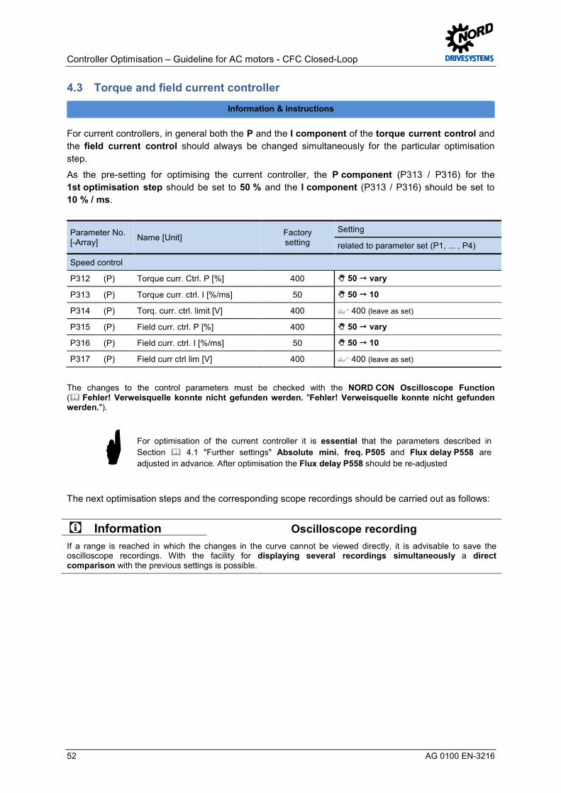
Controller Optimisation – Guideline for AC motors - CFC Closed-Loop
52 AG 0100 EN-3216
4.3 Torque and field current controller Pos: 169 /Appli kati onen/[AG 0100 - AG 0101] allgemei ngültige Modul e/Str ukturmodul e/Infor mation & H andlungsanweisung @ 7\mod_1434981091960_388.docx @ 228011 @ @ 1
Information & instructions
Pos : 173 /Appli kati onen/[AG 0100] Regl eropti mier ung ASM - CFC Cl osed-Loop/4. Stromr egelung/Momenten- und Fel dstr omregler @ 5\mod_1400586993304_388.docx @ 133531 @ @ 1
For current controllers, in general both the P and the I component of the torque current control and the field current control should always be changed simultaneously for the particular optimisation step.
As the pre-setting for optimising the current controller, the P component (P313 / P316) for the 1st optimisation step should be set to 50 % and the I component (P313 / P316) should be set to 10 % / ms.
Parameter No. [-Array] Name [Unit] Factory
setting Setting
related to parameter set (P1, ... , P4)
Speed control
P312 (P) Torque curr. Ctrl. P [%] 400 50 vary
P313 (P) Torque curr. ctrl. I [%/ms] 50 50 10
P314 (P) Torq. curr. ctrl. limit [V] 400 400 (leave as set)
P315 (P) Field curr. ctrl. P [%] 400 50 vary
P316 (P) Field curr. ctrl. I [%/ms] 50 50 10
P317 (P) Field curr ctrl lim [V] 400 400 (leave as set)
The changes to the control parameters must be checked with the NORD CON Oscilloscope Function ( Fehler! Verweisquelle konnte nicht gefunden werden. "Fehler! Verweisquelle konnte nicht gefunden werden.").
For optimisation of the current controller it is essential that the parameters described in Section 4.1 "Further settings" Absolute mini. freq. P505 and Flux delay P558 are adjusted in advance. After optimisation the Flux delay P558 should be re-adjusted
The next optimisation steps and the corresponding scope recordings should be carried out as follows:
Information Oscilloscope recording If a range is reached in which the changes in the curve cannot be viewed directly, it is advisable to save the oscilloscope recordings. With the facility for displaying several recordings simultaneously a direct comparison with the previous settings is possible. Pos: 175 /Appli kati onen/[AG 0100] Regl eropti mier ung ASM - CFC Cl osed-Loop/4. Stromr egelung/P- Anteil e Stromr egler @ 5\mod_1401807371901_388.docx @ 134918 @ 3 @ 1
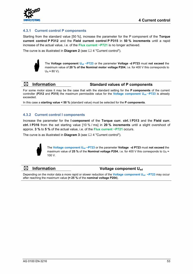
4 Current control
AG 0100 EN-3216 53
4.3.1 Current control P components Starting from the standard value [50 %], increase the parameter for the P component of the Torque current control P P312 and the Field current control P P315 in 50 % increments until a rapid increase of the actual value, i.e. of the Flux current ~P721 is no longer achieved.
The curve is as illustrated in Diagram 2 (see 4 "Current control").
The Voltage component Usd ~P723 or the parameter Voltage -d P723 must not exceed the maximum value of 20 % of the Nominal motor voltage P204, i.e. for 400 V this corresponds to UN ≈ 80 V).
Information Standard values of P components For some motor sizes it may be the case that with the standard setting for the P components of the current controller (P312 and P315) the maximum permissible value for the Voltage component Usd ~P723 is already exceeded.
In this case a starting value < 50 % (standard value) must be selected for the P components. Pos: 177 /Appli kati onen/[AG 0100] Regl eropti mier ung ASM - CFC Cl osed-Loop/4. Stromr egelung/I- Anteile Stromregl er @ 5\mod_1401807465709_388.docx @ 134941 @ 3 @ 1
4.3.2 Current control I components Increase the parameter for the I component of the Torque curr. ctrl. I P313 and the Field curr. ctrl. I P316 from the set starting value [10 % / ms] in 20 % increments until a slight overshoot of approx. 3 % to 5 % of the actual value, i.e. of the Flux current ~P721 occurs.
The curve is as illustrated in Diagram 3 (see 4 "Current control").
The Voltage component Usd ~P723 or the parameter Voltage -d P723 must not exceed the maximum value of 25 % of the Nominal voltage P204, i.e. for 400 V this corresponds to UN ≈ 100 V.
Information Voltage component Usd Depending on the motor data a more rapid or slower reduction of the Voltage component Usd ~P723 may occur after reaching the maximum value (≈ 25 % of the nominal voltage P204). Pos: 179 /Appli kati onen/[AG 0100 - AG 0101] allgemei ngültige Modul e/4. Str omregel ungKriteri en @ 5\mod_1404208366058_388.docx @ 139559 @ 3 @ 1

Controller Optimisation – Guideline for AC motors - CFC Closed-Loop
54 AG 0100 EN-3216
4.3.3 Criteria The following criteria should be noted for optimisation of the field weakening control:
The aim is to optimise the curve for the Flux current ~P721 with the "correct" settings of the P and I components.
• Keep the rise time of the Flux current ~P721 to a minimum • Aim for a maximum overshoot of 3 – 5 % of the Magnetisation current ~P721 • Only allow an amplitude of the Voltage component Usd ~P723 which does not
exceed 20 % or 25 % of the Nominal voltage P204
Information Optimisation steps The step widths stated for control optimisation may differ depending on the application. Furthermore, the step widths can be selected even finer for the final optimisation steps. Pos: 182 /Appli kati onen/[AG 0100 - AG 0101] allgemei ngültige Modul e/Allgemei n gül tige Ü berschriften/Opti mi erungsablauf [Ü2] @ 7\mod_1432029832970_388.docx @ 220967 @ 2 @ 1

4 Current control
AG 0100 EN-3216 55
4.4 Optimisation procedure Pos: 183 /Appli kati onen/[AG 0100 - AG 0101] allgemei ngültige Modul e/Str ukturmodul e/H andlungsanweisung @ 7\mod_1434979210308_388.docx @ 227979 @ @ 1
Instructions
Pos : 184 /Appli kati onen/[AG 0100] Regl eropti mier ung ASM - CFC Cl osed-Loop/4. Stromr egelung/Opti mi erungsablauf @ 5\mod_1401197988384_388.docx @ 134504 @ @ 1
Information Short circuit detection It is possible that an oscillation may occur at the start of the curve. This oscillation occurs with frequency inverters with an integrated "automatic short circuit detection".
This has no effect on the optimisation of the current controller.
Automatic short circuit measurement for SK 200E frequency inverter, 4.0 kW asynchronous motor (IE2)
Legend Field setpoint vs. Weak field Flux current ~P721 Voltage component ~P723
Fig. 28: Short circuit measurement of SK 200E frequency inverter
The following illustrations show the optimisation process for the current controller using the example of a 4.0 kW asynchronous motor with efficiency class IE2 on the basis of individual oscilloscope recordings.

Controller Optimisation – Guideline for AC motors - CFC Closed-Loop
56 AG 0100 EN-3216
Legend Field setpoint vs. Weak field Flux current ~P721 Voltage component ~P723 Step 1. "P" scope recording 2. "P" scope recording
Parameter settings
P312 / P315 = 50 % P313 / P316 = 10 % / ms
P312 / P315 = 100 % P313 / P316 = 10 % / ms
Step 6. "P" scope recording 7. "P" scope recording
Parameter settings
P312 / P315 = 300 % P313 / P316 = 10 % / ms
P312 / P315 = 350 % P313 / P316 = 10 % / ms
Step 8. "P" scope recording 11. "P" scope recording
Parameter settings
P312 / P315 = 400 % P313 / P316 = 10 % / ms
P312 / P315 = 600 % P313 / P316 = 10 % / ms
Fig. 29: Curve for the P component of the current control
Starting point P component P iti "
P component
P component far too high
P component too high
P component
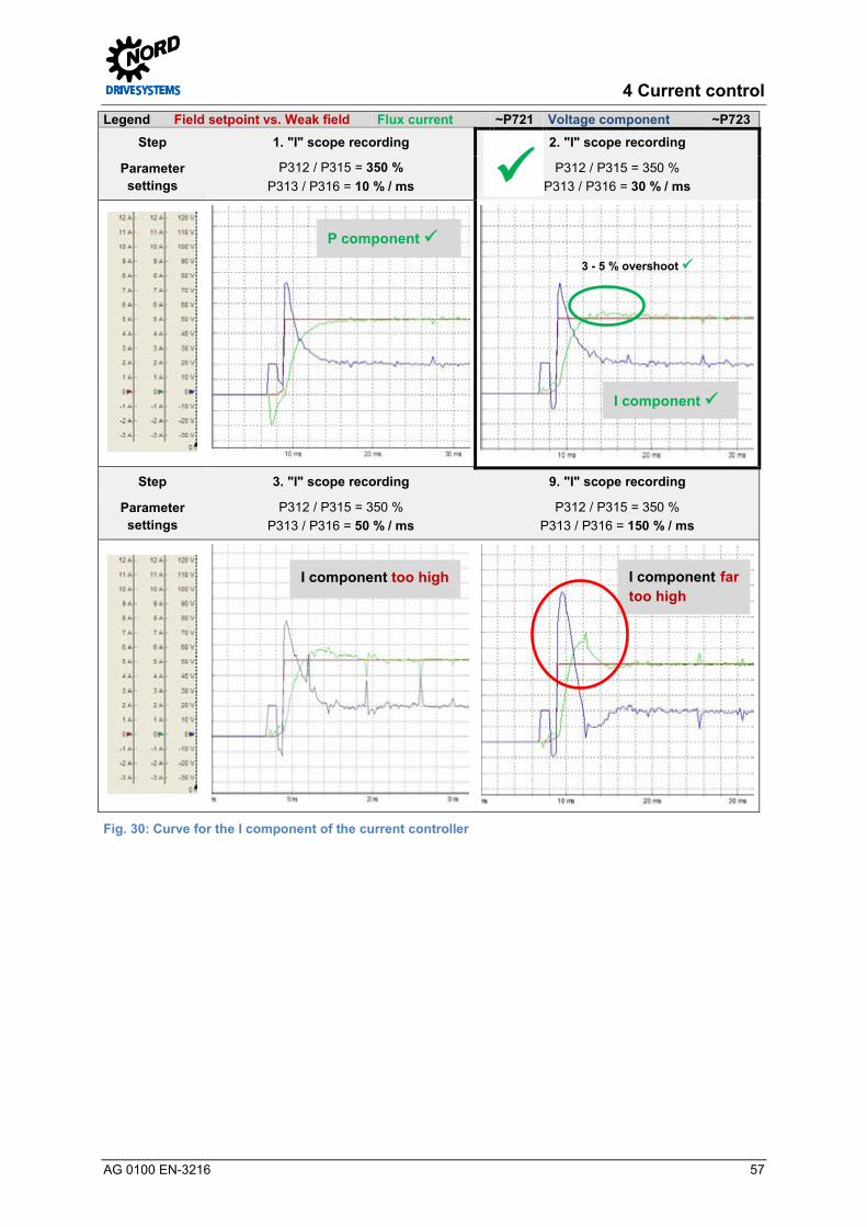
4 Current control
AG 0100 EN-3216 57
Legend Field setpoint vs. Weak field Flux current ~P721 Voltage component ~P723 Step 1. "I" scope recording 2. "I" scope recording
Parameter settings
P312 / P315 = 350 % P313 / P316 = 10 % / ms
P312 / P315 = 350 % P313 / P316 = 30 % / ms
Step 3. "I" scope recording 9. "I" scope recording
Parameter settings
P312 / P315 = 350 % P313 / P316 = 50 % / ms
P312 / P315 = 350 % P313 / P316 = 150 % / ms
Fig. 30: Curve for the I component of the current controller Pos: 194 /Appli kati onen/[AG 0100 - AG 0101] allgemei ngültige Modul e/5. Drehzahlreg elung/Drehzahlreg elung [Ü 1] @ 7\mod_1431930963044_388.docx @ 219913 @ 1 @ 1
3 - 5 % overshoot
I component
I component too high I component far too high
P component

Controller Optimisation – Guideline for AC motors - CFC Closed-Loop
58 AG 0100 EN-3216
5 Speed control Pos: 196 /Appli kati onen/[AG 0100 - AG 0101] allgemei ngültige Modul e/Str ukturmodul e/Schrit t 5 @ 7\mod_1434978705685_388.docx @ 227756 @ @ 1
Step 5
Pos : 197 /Appli kati onen/[AG 0100 - AG 0101] allgemei ngültige Modul e/Str ukturmodul e/Infor mation @ 7\mod_1434979005376_388.docx @ 227948 @ @ 1
Information
Pos : 198 /Appli kati onen/[AG 0100] Regl eropti mier ung/5. Dr ehzahlregel ung/Drehzahlreg elung @ 5\mod_1401969536339_388.docx @ 135900 @ 5 @ 1
The speed controller is a PI controller and comprises the two following parameters.
• Speed controller (P310, P311)
The parameter Speed Ctrl P P310 influences the P component of the controller. For the I component the parameter Speed Ctrl I P311 is available.
It is recommended that the following optimisation steps are performed to systematically adjust the speed controller for constant loads.
Overview of optimisation procedure
• Set the I component to a low value
• Set the P component to a low value and e.g. increase in 50 % increments until the Torque current ~P720 has a curve which is as rectangular as possible. The Speed encoder ~P735 should have a linearly increasing curve.
• This is followed by the increase of the I component in e.g. 5 % / ms increments, in order to further optimise the rectangular curve of the Torque current ~P720. This optimisation causes a slight overshoot of the speed.
The aim is to optimise the curve for the Torque current ~P720 with the "correct" settings of the P and I components. The practical implementation for optimisation of a speed controller is described in Section 5.4 "Optimisation procedure".
Pos: 200 /Appli kati onen/[AG 0100 - AG 0101] allgemei ngültige Modul e/Allgemei n gül tige Ü berschriften/Wei ter e Ei nstellungen [Ü2] @ 7\mod_1432029630965_388.docx @ 220873 @ 2 @ 1
5.1 Further settings Pos: 201 /Appli kati onen/[AG 0100 - AG 0101] allgemei ngültige Modul e/Str ukturmodul e/H andlungsanweisung @ 7\mod_1434979210308_388.docx @ 227979 @ @ 1
Instructions
Pos : 202 /Appli kati onen/[AG 0100] Regl eropti mier ung ASM - CFC Cl osed-Loop/5. Drehzahlr egelung/Wei ter e Eins tell ungen @ 5\mod_1401969537297_388.docx @ 135924 @ 5 @ 1
For optimisation of the speed controller, it is essential that the following two parameters are set in advance.
Parameter No. [-Array] Name [Unit] Factory
setting Setting
related to parameter set (P1, ... , P4)
ADDITIONAL PARAMETERS
P558 (P) Flux delay [ms] 1 0 1 (back to standard)
The ramp time must be set under the "Basic Parameters" tab in the parameter Acceleration time P102.
5 Speed control
AG 0100 EN-3216 59
Parameter No. [-Array] Name [Unit] Factory
setting Setting
related to parameter set (P1, ... , P4)
BASIC PARAMETERS
P102 (P) Acceleration time [s] 2.0 2.0 0.08 *
P113 (P) Jog frequency [Hz] 0.0 0.0 35
* Notice: this is set without load in the example
Information Brake applications For applications with a brake, the parameter Brake reaction time P107 as well as the Brake delay off P114 must be parameterised for the optimisation of the controller.
Otherwise a fault message will occur, as the drive goes into fault status due to the applied brake.
Information Setpoint / Weak field range Optimisation of the speed controller must be performed below the weak field range ( 8 "Weak field controller")!
Because of this, the setpoint specification must be matched to the design range (50 Hz / 87 Hz / 100 Hz – curves). For a standard design according to the 50 Hz characteristic curve the setpoint (frequency) should be approx. 70 % ≈ 35 Hz.
For applications with an extended operating point (87 Hz or 100 Hz characteristic curve) a setpoint (frequency) in the range of approx. 70 - 80 % (i.e. 61 - 70 Hz or 70 - 80 Hz) must be specified. The weak field range for this application therefore begins above approx. 45 Hz.
The setting for the Acceleration time P102 must be selected so that if possible, the Torque current ~P720 achieves 50 % - 100 % of the nominal current P203 (see type plate / nominal motor current) with the optimisation.
Setting of the Torque current ~P720 (Isq) sollte mit Hilfe der NORD CON Oszilloskop Funktion vorgenommen werden.
Before starting the oscilloscope recording and enabling the drive unit, the setpoint must be set to a value of approx. 70 - 80 % of the Nominal frequency P201 (50 Hz). I.e. in this example (4.0 kW frequency inverter / motor combination) a setpoint frequency of approx. 35 - 40 Hz must be specified.
Calculation of the torque current
The Torque current ~P720 (Isq) which is to be achieved is calculated according to the formula:
𝑰𝑰𝒔𝒔𝒔𝒔 = (𝑰𝑰𝒔𝒔² − 𝑰𝑰𝒔𝒔𝒔𝒔²)
In the basic speed range, up to the rated frequency Isd = I0 = no load current. Is: Line motor current (Display ~P203) [A] Isq: Torque-forming current or rotor current (≈ P720) [A] Isd: Flux-forming current or no load current (P209 / ≈ P721) [A]
For further information regarding the calculation please refer to Section 1.2 "Field-orientated control"

Controller Optimisation – Guideline for AC motors - CFC Closed-Loop
60 AG 0100 EN-3216
Pos: 204 /Appli kati onen/[AG 0100 - AG 0101] allgemei ngültige Modul e/Allgemei n gül tige Ü berschriften/NORD CON [Ü 2] @ 7\mod_1432029689942_388.docx @ 220904 @ 2 @ 1
5.2 NORD CON Pos: 205 /Appli kati onen/[AG 0100 - AG 0101] allgemei ngültige Modul e/Str ukturmodul e/Infor mation & H andlungsanweisung @ 7\mod_1434981091960_388.docx @ 228011 @ @ 1
Information & instructions
Pos : 206 /Appli kati onen/[AG 0100 - AG 0101] allgemei ngültige Modul e/Allgemei n gül tige Ü berschriftenNORD C ON [Kurzfassung] @ 5\mod_1403614918300_388.docx @ 137991 @ @ 1
Further information about the settings can be obtained from Section 4.2 "NORD CON" and the following. Pos: 207 /Appli kati onen/[AG 0100] Regl eropti mier ung ASM - CFC Cl osed-Loop/5. Drehzahlr egelung/Fernbedi enen @ 5\mod_1403614155380_388.docx @ 137944 @ 3 @ 1
5.2.1 Remote control The following setting must be made in the Remote Control screen to optimise the speed controller before starting the scope recordings.
Set the setpoint to 70 %, i.e.set the setpoint frequency to 35 Hz
Use the + value or the - value button
Press the OK button to save the frequency as the jog frequency in P113
Press the Enable button
Steps and are not required if a jog frequency has been parameterised.
Fig. 31: Remote control of the speed controller, setpoint and enabling Pos: 209 /Appli kati onen/[AG 0100] Regl eropti mier ung ASM - CFC Cl osed-Loop/5. Drehzahlr egelung/Oszilloskop @ 10\mod_1455023754476_388.docx @ 289502 @ 3 @ 1

5 Speed control
AG 0100 EN-3216 61
5.2.2 Oscilloscope The following settings should be made under the two tabs Recording or Channel Settings of the NORD CON Oscilloscope Function before starting the oscilloscope recordings. The settings and graphic displays in the illustrations may differ according to the frequency inverter types, versions and software status.
Set Trigger to Enable
Set the scan rate to 5 ms → Scan duration 1 s → Scan rate depending on the run up time which is set Note The scan rate should be selected so that it corresponds to the scope recordings in the illustrations in Section 5.4 "Optimisation procedure"!
Fig. 32: Oscilloscope settings for trigger and scan rate / scan duration
Fig. 33: Resolution settings for the time axis, comment examples
Fig. 34: Oscilloscope channel settings for the four measurement values

Controller Optimisation – Guideline for AC motors - CFC Closed-Loop
62 AG 0100 EN-3216
Press the Start button Note Note the initialisation phase, see the illustrations in Section Fehler! Verweisquelle konnte nicht gefunden werden. "Fehler! Verweisquelle konnte nicht gefunden werden."
Fig. 35: Start the scope recording Pos: 211 /Appli kati onen/[AG 0100 - AG 0101] allgemei ngültige Modul e/5. Drehzahlreg elung/Drehzahlregler @ 7\mod_1432040250905_388.docx @ 221030 @ 2 @ 1
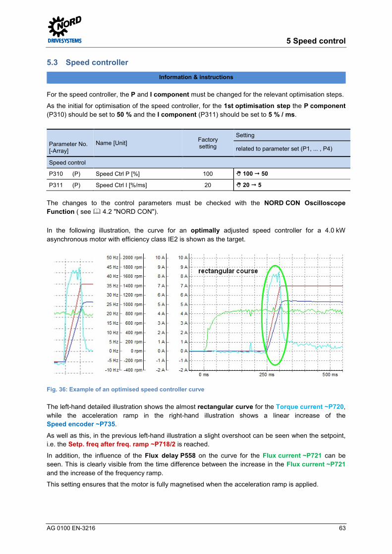
5 Speed control
AG 0100 EN-3216 63
5.3 Speed controller Pos: 212 /Appli kati onen/[AG 0100 - AG 0101] allgemei ngültige Modul e/Str ukturmodul e/Infor mation & H andlungsanweisung @ 7\mod_1434981091960_388.docx @ 228011 @ @ 1
Information & instructions
Pos : 213 /Appli kati onen/[AG 0100] Regl eropti mier ung ASM - CFC Cl osed-Loop/5. Drehzahlr egelung/Drehzahlr egler @ 5\mod_1401969538622_388.docx @ 135972 @ @ 1
For the speed controller, the P and I component must be changed for the relevant optimisation steps.
As the initial for optimisation of the speed controller, for the 1st optimisation step the P component (P310) should be set to 50 % and the I component (P311) should be set to 5 % / ms.
Parameter No. [-Array]
Name [Unit] Factory setting
Setting
related to parameter set (P1, ... , P4)
Speed control
P310 (P) Speed Ctrl P [%] 100 100 50
P311 (P) Speed Ctrl I [%/ms] 20 20 5
The changes to the control parameters must be checked with the NORD CON Oscilloscope Function ( see 4.2 "NORD CON").
In the following illustration, the curve for an optimally adjusted speed controller for a 4.0 kW asynchronous motor with efficiency class IE2 is shown as the target.
Fig. 36: Example of an optimised speed controller curve
The left-hand detailed illustration shows the almost rectangular curve for the Torque current ~P720, while the acceleration ramp in the right-hand illustration shows a linear increase of the Speed encoder ~P735.
As well as this, in the previous left-hand illustration a slight overshoot can be seen when the setpoint, i.e. the Setp. freq after freq. ramp ~P718/2 is reached.
In addition, the influence of the Flux delay P558 on the curve for the Flux current ~P721 can be seen. This is clearly visible from the time difference between the increase in the Flux current ~P721 and the increase of the frequency ramp.
This setting ensures that the motor is fully magnetised when the acceleration ramp is applied.

Controller Optimisation – Guideline for AC motors - CFC Closed-Loop
64 AG 0100 EN-3216
The display of the required rectangular form of the Torque current ~P720 curve during the acceleration ramp may differ, as the curve results from the requirements specific to the application.
The following illustration shows the form of the curve of the P component of the speed encoder is set too high. The value of the Speed control P P310 which is too high results in oscillation of the Torque current ~P720.
Fig. 37: Example with an excessive P component of the speed controller
The next optimisation steps and scope recordings should be carried out as follows:
Information Oscilloscope recording If a range is reached in which the changes in the curve cannot be viewed directly, it is advisable to save the oscilloscope recordings. With the facility for displaying several recordings simultaneously a direct comparison with the previous settings is possible. Pos: 215 /Appli kati onen/[AG 0100] Regl eropti mier ung ASM - CFC Cl osed-Loop/5. Drehzahlr egelung/P-Anteil Drehzahlregler @ 5\mod_1402565516619_388.docx @ 136450 @ 3 @ 1

5 Speed control
AG 0100 EN-3216 65
5.3.1 Speed control P component Increase the parameter for the P component in 50 % increments until the curve for the Torque current ~P720 is as rectangular as possible. The Speed encoder ~P735 should have a linearly increasing curve.
The curve is as illustrated in the second illustration (see 5.3 "Speed controller").
The upper adjustment limit of the Speed Ctrl P P310 is reached, when a further increase of the P component does not result in a better shape of the curve in the sense of a rectangular shape. A setting of the P component which is too high can cause oscillations of the Torque current ~P720 as well as in the Speed encoder ~P735.
Once the P component has been determined, in operation, the controller must be slowly run down from the setpoint frequency (e.g. 35 Hz) to 0 - 3 Hz. It must be checked that during the brake ramp the torque current ~P720 remains free from oscillations. Among other things, this is used to test whether the P component is set correctly for all speeds. If the P component is set too high for a selected speed (setpoint specification), this is apparent from oscillations in the Torque current ~P720 and an associated production of noise "scratching noise" during operation or during the movement profile.
Pos: 217 /Appli kati onen/[AG 0100] Regl eropti mier ung ASM - CFC Cl osed-Loop/5. Drehzahlr egelung/I- Anteil Dr ehzahlregler @ 5\mod_1402577369506_388.docx @ 136650 @ 3 @ 1
5.3.2 Speed controller I component Beginning from the set starting value [5 % / ms] increase the I component in small increments (e.g. 5 %) until an approximately rectangular curve results for the act. torque current ~P720.
Information I component increment If the application has a high inertial mass (relative to the inertia of the motor), the increment should not exceed > 5 % / ms.
If the ratio Janw / JMotor is small, the increase of the I- component can be performed in larger increments.
The selected increment for the increase of the I component should be in the range from 5 to 20.
As a result of the increase of the I component there is a slight overshoot of the Speed encoder ~P735. If the I component is set too high the rectangular form of the Torque current ~P720 will be distorted upward to the left.
The curve is according to that in the scope recording for Step 6: "I" scope recording 5.4 "Optimisation procedure".
Once the I component has been determined, in operation, the controller must be slowly run down from the setpoint frequency (e.g. 35 Hz) to 0 - 3 Hz. It must be checked that during the brake ramp the Torque current ~P720 remains free from oscillations. Among other things, this is used to test whether the I component is set correctly for all speeds. If the PI component is set too high for a selected speed (setpoint specification), this is apparent from oscillations in the Torque current ~P720 and an associated production of noise "scratching noise" during operation or during the movement profile.
Pos: 219 /Appli kati onen/[AG 0100 - AG 0101] allgemei ngültige Modul e/5. Drehzahlreg elungKriteri en @ 5\mod_1404208496122_388.docx @ 139582 @ 3 @ 1

Controller Optimisation – Guideline for AC motors - CFC Closed-Loop
66 AG 0100 EN-3216
5.3.3 Criteria The following criteria should be noted for optimisation of the field speed controller:
The aim is to optimise the curve for the Torque current ~P720 taking the criteria into account, with the "correct" settings of the P and I components.
• The curve for the Speed encoder ~P735 should be linear and free from oscillations
• No, or slight oscillation (approx.. 3 – 5 %) when the setpoint of the Speed encoder ~P735 is reached during optimisation of the I component
• Rectangular form of the Torque current ~P720 in the acceleration phase • No oscillations in the curve for the Torque current ~P720 after completion of
the acceleration phase • No "scratching noises" when the drive unit is in operation
During operation there may be a "scratching noise", which is primarily apparent in applications with drive units ≥ 3 kW If noises are produced, the P or also the I component should be reduced.
Information Optimisation steps The step widths stated for control optimisation may differ depending on the application. Furthermore, the step widths can be selected even finer for the final optimisation steps. Pos: 234 /Appli kati onen/[AG 0100 - AG 0101] allgemei ngültige Modul e/Allgemei n gül tige Ü berschriften/Opti mi erungsablauf [Ü2] @ 7\mod_1432029832970_388.docx @ 220967 @ 2 @ 1
5.4 Optimisation procedure Pos: 235 /Appli kati onen/[AG 0100 - AG 0101] allgemei ngültige Modul e/Str ukturmodul e/H andlungsanweisung @ 7\mod_1434979210308_388.docx @ 227979 @ @ 1
Instructions
Pos : 236 /Appli kati onen/[AG 0100] Regl eropti mier ung ASM - CFC Cl osed-Loop/5. Drehzahlr egelung/Opti mi erungsablauf @ 5\mod_1401969540933_388.docx @ 136068 @ @ 1
The following illustrations show the optimisation process for the speed controller using the example of a 4.0 kW asynchronous motor with efficiency class IE2 on the basis of individual scope recordings.
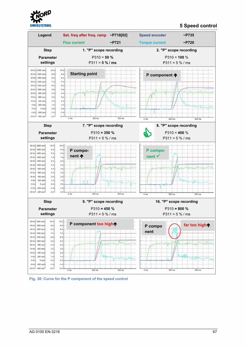
5 Speed control
AG 0100 EN-3216 67
Legend Set. freq after freq. ramp ~P718[02] Speed encoder ~P735
Flux current ~P721 Torque current ~P720
Step 1. "P" scope recording 2. "P" scope recording
Parameter settings
P310 = 50 % P311 = 5 % / ms
P310 = 100 % P311 = 5 % / ms
Step 7. "P" scope recording 8. "P" scope recording
Parameter settings
P310 = 350 % P311 = 5 % / ms
P310 = 400 % P311 = 5 % / ms
Step 9. "P" scope recording 16. "P" scope recording
Parameter settings
P310 = 450 % P311 = 5 % / ms
P310 = 800 % P311 = 5 % / ms
Fig. 38: Curve for the P component of the speed control
Starting point P component
P compo-nent
P compo-nent
P component too high P component
far too high

Controller Optimisation – Guideline for AC motors - CFC Closed-Loop
68 AG 0100 EN-3216
Legend Set. freq after freq. ramp ~P718[02] Speed encoder ~P735
Flux current ~P721 Torque current ~P720
Step 1. "I" scope recording 2. "I" scope recording
Parameter settings
P310 = 400 % P311 = 5 % / ms
P310 = 400 % P311 = 10 % / ms
Step 5. "I" scope recording 6. "I" scope recording
Parameter settings
P310 = 400 % P311 = 25 % / ms
P310 = 400 % P311 = 30 % / ms
Step 7. "I" scope recording 30. "I" scope recording
Parameter settings
P310 = 400 % P311 = 35 % / ms
P310 = 400 % P311 = 150 % / ms
Fig. 39: Curve for the I component of the speed control Pos: 239 /Appli kati onen/[AG 0100 - AG 0101] allgemei ngültige Modul e/6. Lagereg elung/Lager egelung [Ü 1] @ 7\mod_1431931000798_388.docx @ 219944 @ 1 @ 1
Starting point I component
I component I component
I component too high I component far too high

6 Position control
AG 0100 EN-3216 69
6 Position control Pos: 241 /Appli kati onen/[AG 0100 - AG 0101] allgemei ngültige Modul e/Str ukturmodul e/Schrit t 6 @ 7\mod_1434978709941_388.docx @ 227788 @ @ 1
Step 6
Pos : 242 /Appli kati onen/[AG 0100 - AG 0101] allgemei ngültige Modul e/Str ukturmodul e/Infor mation @ 7\mod_1434979005376_388.docx @ 227948 @ @ 1
Information
Pos : 243 /Appli kati onen/[AG 0100 - AG 0101] allgemei ngültige Modul e/6. Lagereg elungLagereg elung @ 5\mod_1402039391529_388.docx @ 136294 @ 55 @ 1
The position control can be used in combination with an encoder to provide a high precision positioning drive. Usually, various encoder systems e.g. incremental encoders or absolute encoders are used to provide speed feedback. These are used as measurement transducers, which convert the rotary movements and positioning data (position) into electrical signals.
The choice of the encoder system depends on the requirements of the application. This includes the following characteristics, such as:
• Encoder type: Absolute or incremental encoder • Encoder type (TTL, HTL, combination, single-, multiturn) / resolution • Application type (angle measurement, linear travel measurement) • Connection method, interface drivers, filed bus system, with cable or plug-in • Construction and mounting type (flange, shaft, hollow shaft, torque support, etc.) • Electronic features (power supply, output drivers, etc.) • Ambient conditions (protection type, temperature, ATEX, etc.)
Information Encoder selection HTL incremental encoders (IG) as well as CANopen absolute encoders (AG) can be used for decentralised SK 2xxE frequency encoders. TTL incremental encoders and CANopen absolute encoders can be used for control cabinet frequency inverters ≥ SK 530E.
In addition, for performance level SK 540E, SIN/COS encoders and other absolute encoder types such as Hiperface, Endat, SSI and BiSS encoders can be connected to its universal encoder interface.
For detailed information regarding the particular encoder types, please refer to the relevant supplementary manual POSICON Positioning Control, see BU 0210 or BU 0510 10.1 "Manuals".
The following features and integrated frequency inverter functions are available for positioning control:
• Programmable position memory - For SK 2x5E there are 63 absolute positions - For SK 53xE there are 63 absolute positions - For SK 54xE there are 252 absolute positions
• Positions are also maintained with "severe" load fluctuations • Time-optimised and safe travel up to the target position by means of path calculation function • In addition to travelling to absolute positions, up to 4 step lengths (so-called position
increments) can be stored in the frequency inverter. • Positions can also be saved in a control unit and specified via an appropriate field bus
interface (e.g. CANopen) • The positions can be transferred to the frequency inverter via a field bus interface
Controller Optimisation – Guideline for AC motors - CFC Closed-Loop
70 AG 0100 EN-3216
NOTICE Power supply
Only encoder types with a 10 - 30 V supply may be used for frequency inverter applications.
For the POSICON positioning function, additional parameters (P6xx) which are required for the position control are available under the Positioning tab as a separate menu group.
Information Enabling POSICON For decentralised SK 2xxE frequency inverters the Positioning tab is enabled with the parameter Supervisor-Code P003 3 = All parameters visible.
For SK 530E control cabinet frequency inverters the Positioning tab P6xx is enabled as the default in the factory settings.
Application information
• The positioning function / configuration and control of the frequency inverter as well as the specification of the position setpoint can be made via the
- Digital inputs - Bus IO In Bits - USS protocol or a field bus system (e.g. PROFIBUS DP, CANopen etc.)
• Position detection can be performed with incremental or absolute encoders • Switch-over from speed control and position control (positioning) using parameter switch-
over • Synchronisation functionality between master and slave drives (one or more) using the
integrated system bus interface • Endless axis function (Modulo axes) for turntables and similar applications (this controls an
endless axis) with optimised path. The drive unit turns clockwise or anticlockwise according to the required position.
For example, the frequency inverter is controlled using a specified position described by positions which are saved in the frequency inverter. In this example, the specification of the position and enabling of the drive unit is implemented via the BUS IO In bits. An incremental encoder (IG) or a standard CANopen combination absolute encoder as well as other types of rotary encoder (only ≥ SK 540E) can be used for the encoder system.
It is recommended that the following optimisation steps are performed to systematically adjust a position controller:
Information Application notes for brake resistor An external brake resistor was used for the optimisation of the position control described in this guide, see 2.1 "System components". The selection of an internal or external brake resistor for the SK 2xxE results from the application requirements.

6 Position control
AG 0100 EN-3216 71
Overview of optimisation procedure
• Select the encoder system and parameterise it accordingly • Connect the encoder system and test the function • Select and parameterise the interface for the setpoint or position specification • Set the acceleration and braking ramps, i.e. Acceleration time P102 and Deceleration
time P103 • Selection / Specification of the setpoint or target position
• Set the P component to a small value and e.g. increase this in 10% increments until the speed curve is as linear as possible for the Speed encoder =P735. In this case, a limit due to the brake ramp / Deceleration time (P103) should be apparent and effective.
• If the P component is set too high, this is apparent from oscillations of the Speed encoder =P735 in the actual position when braking. In addition there is an overshoot of the Torque current ~P720 in this range. In this case, the P component must be reduced again.
Fig. 40: Position control movement profile
For detailed information regarding the movement profile or the parameters which have to be set, please refer to the relevant supplementary manual POSICON Positioning Control (BU 0210 or BU 0510 see 10.1 "Manuals"). In addition, the relevant parameters are described in Sections 6.4 "Position controller" and 6.4.3 "Positioning".
The aim is to obtain the optimum curve of the movement profile with the "correct" setting of the P component. The Speed encoder ~P735 should follow the braking ramp and should not pass over the setpoint position. The practical implementation for optimisation of a position controller is described in Section 6.5 "Optimisation procedure".
Pos: 245 /Appli kati onen/[AG 0100 - AG 0101] allgemei ngültige Modul e/Allgemei n gül tige Ü berschriften/Wei ter e Ei nstellungen [Ü2] @ 7\mod_1432029630965_388.docx @ 220873 @ 2 @ 1

Controller Optimisation – Guideline for AC motors - CFC Closed-Loop
72 AG 0100 EN-3216
6.1 Further settings Pos: 246 /Appli kati onen/[AG 0100 - AG 0101] allgemei ngültige Modul e/Str ukturmodul e/H andlungsanweisung @ 7\mod_1434979210308_388.docx @ 227979 @ @ 1
Instructions
Pos : 247 /Appli kati onen/[AG 0100] Regl eropti mier ung ASM - CFC Cl osed-Loop/6. Lager egel ung/Weiter e Eins tell ung en @ 5\mod_1404986150741_388.docx @ 140044 @ @ 1
For optimisation of the position controller, the following two parameters must be set in advance. Some of the setting are listed here in order to illustrate the control, position specification and position selection with BUS IO In Bits or the USS interface. However, this may differ according to the application.
Information Application information The ramp times for the Acceleration time P102, the Deceleration time P103 and the setpoint specification (required speed) result from the requirements of the application. For use of the slow movement function at the end of a positioning procedure, the minimum frequency P104 must be taken into account. This is used during slow movement.
The ramp time must be set under the "Basic Parameters" tab in the parameter Acceleration time P102 and Deceleration time P103.
Parameter No. [-Array] Name [Unit] Factory
setting Setting
related to parameter set (P1, ... , P4)
BASIC PARAMETERS
P102 (P) Acceleration time [s] 2.0 2.0 0.3 *
P103 (P) Deceleration time [s] 2.0 2.0 0.3 *
P104 (P) Minimum frequency [Hz] 0.0 0.0 … **
CONTROL TERMINALS
P480 [-11] Funct. Bus I/O In Bits Bit 8 Bus control word 0 0 55 (Bit 0 position (increment) array)
ADDITIONAL PARAMETERS
P509 Source Control Word 0 0 2 (USS)
P510 [-01] Source Setpoints Source main setvalue 0 (Auto) 0 (leave as set) ***
P510 [-02] Source Setpoints Source 2nd setpoint 0 (Auto) 0 (leave as set) ***
* To be set according to the specific application (Notice: in this example without load)
** To be set according to the specific application (Note: only relevant for slow running / Pos. Window P612)
*** Leave P510 Source main setvalue at the factory setting (0 = Auto)
Information Setpoint and position specification The setpoint specification and the setting of the Position Control P600 should correspond to the design range (50 Hz / 87 Hz / 100 Hz characteristic curves).
For optimisation of the position control, the setpoint should be selected according to the application requirements! For the SK 200E frequency inverter / motor combination (4.0 kW) and the supply voltage of 400 V (50 Hz) described in this guide, the function 2 = Lin. ramp (setpoint frequency) is set and a specified setpoint of e.g. 45 % is selected.

6 Position control
AG 0100 EN-3216 73
Optimisation of the position control should be made with the aid of the NORD CON oscilloscope function.
Before starting the scope recording and enabling the drive unit, the setpoint is set to 45 % I.e. in this example (frequency inverter 4.0 kW / motor combination 4.0 kW) a setpoint frequency of 22.5 Hz is specified. It should be noted that the setpoint position "0" is used as the first specified position. From this, it follows that as the second setpoint position "10", in parameter Position P613, only the array [-01] is to be parameterised!
Pos: 249 /Appli kati onen/[AG 0100 - AG 0101] allgemei ngültige Modul e/Allgemei n gül tige Ü berschriften/NORD CON [Ü 2] @ 7\mod_1432029689942_388.docx @ 220904 @ 2 @ 1

Controller Optimisation – Guideline for AC motors - CFC Closed-Loop
74 AG 0100 EN-3216
6.2 NORD CON Pos: 250 /Appli kati onen/[AG 0100 - AG 0101] allgemei ngültige Modul e/Str ukturmodul e/Infor mation & H andlungsanweisung @ 7\mod_1434981091960_388.docx @ 228011 @ @ 1
Information & instructions
Pos : 251 /Appli kati onen/[AG 0100 - AG 0101] allgemei ngültige Modul e/Allgemei n gül tige Ü berschriften/NORD CON [Kurzfassung] @ 5\mod_1403614918300_388.docx @ 137991 @ @ 1
Further information about the settings can be obtained from Section 4.2 "NORD CON" and the following. Pos: 252 /Appli kati onen/[AG 0100] Regl eropti mier ung ASM - CFC Cl osed-Loop/6. Lager egel ung/Steuern @ 5\mod_1404986153559_388.docx @ 140092 @ 3 @ 1
6.2.1 Control The following setting must be made in the Control screen to optimise the position controller before starting the scope recordings.
By pressing the button in the "Standard" view, the control screen changes to the "Detail" view.
Fig. 41: Standard control view
Fig. 42: Control of the speed controller, setpoint and enabling
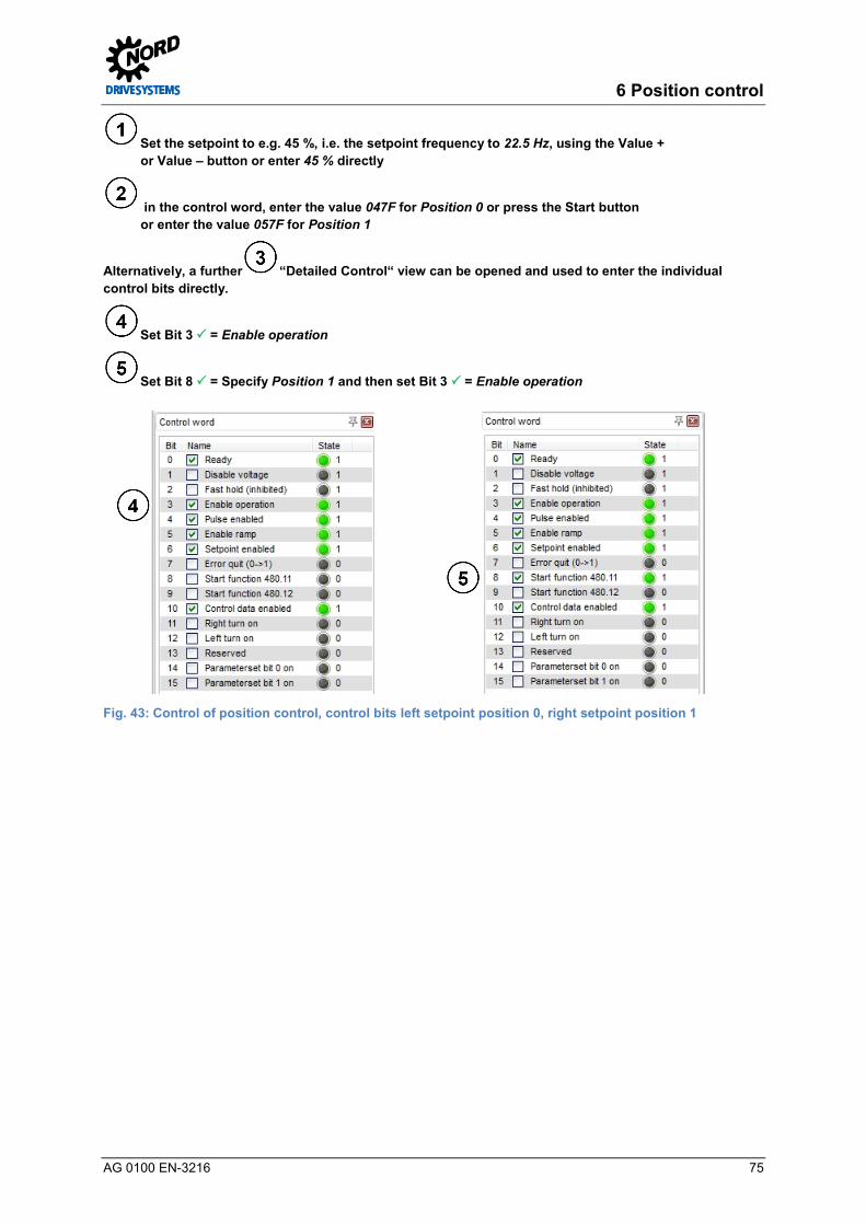
6 Position control
AG 0100 EN-3216 75
Set the setpoint to e.g. 45 %, i.e. the setpoint frequency to 22.5 Hz, using the Value + or Value – button or enter 45 % directly
in the control word, enter the value 047F for Position 0 or press the Start button or enter the value 057F for Position 1
Alternatively, a further “Detailed Control“ view can be opened and used to enter the individual control bits directly.
Set Bit 3 = Enable operation
Set Bit 8 = Specify Position 1 and then set Bit 3 = Enable operation
Fig. 43: Control of position control, control bits left setpoint position 0, right setpoint position 1 Pos: 254 /Appli kati onen/[AG 0100 - AG 0101] allgemei ngültige Modul e/6. Lagereg elungOszilloskop @ 5\mod_1404986154645_388.docx @ 140116 @ 3 @ 1
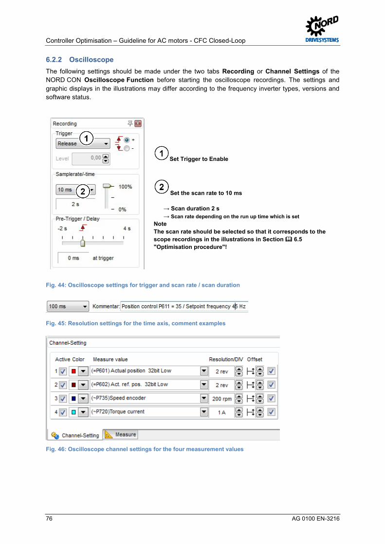
Controller Optimisation – Guideline for AC motors - CFC Closed-Loop
76 AG 0100 EN-3216
6.2.2 Oscilloscope The following settings should be made under the two tabs Recording or Channel Settings of the NORD CON Oscilloscope Function before starting the oscilloscope recordings. The settings and graphic displays in the illustrations may differ according to the frequency inverter types, versions and software status.
Set Trigger to Enable
Set the scan rate to 10 ms → Scan duration 2 s → Scan rate depending on the run up time which is set Note The scan rate should be selected so that it corresponds to the scope recordings in the illustrations in Section 6.5 "Optimisation procedure"!
Fig. 44: Oscilloscope settings for trigger and scan rate / scan duration
Fig. 45: Resolution settings for the time axis, comment examples
Fig. 46: Oscilloscope channel settings for the four measurement values

6 Position control
AG 0100 EN-3216 77
Press the Start button Note Note the initialisation phase, see the illustrations in Section Fehler! Verweisquelle konnte nicht gefunden werden. "Fehler! Verweisquelle konnte nicht gefunden werden."
Fig. 47: Start the scope recording Pos: 255 /Appli kati onen/[AG 0100 - AG 0101] allgemei ngültige Modul e/6. Lagereg elungGeräteübersicht @ 6\mod_1413473004059_388.docx @ 160463 @ 3 @ 1
6.2.3 Device overview The course of positioning can be observed with the following settings of the three display possibilities in the NORD CON Device Overview function.
Setpoint position 1 reached Setpoint position 0 is being approached
Fig. 48: Position control device overview, display settings
Set Display 1 to actual position, set Display 2 to Act. Ref. Pos.
Set Display 3 to Curr. position diff.
Fig. 49: Overview of position control devices, display selection Pos: 256 /Appli kati onen/[AG 0100 - AG 0101] allgemei ngültige Modul e/Allgemei n gül tige D okumente und Ü berschriften/Funktionsprüfung Drehgeber ( IG/AG) [Ü2] @ 9\mod_1444037103123_388.docx @ 248293 @ 2 @ 1

Controller Optimisation – Guideline for AC motors - CFC Closed-Loop
78 AG 0100 EN-3216
6.3 Function test of rotary encoders (IG) Pos: 257 /Appli kati onen/[AG 0100 - AG 0101] allgemei ngültige Modul e/Str ukturmodul e/Infor mation & H andlungsanweisung @ 7\mod_1434981091960_388.docx @ 228011 @ @ 1
Information & instructions
Pos : 258 /Appli kati onen/[AG 0100 - AG 0101] allgemei ngültige Modul e/Allgemei n gül tige Ü berschriftenFunkti onspr üfung Dr ehg eber (IG/AG) @ 5\mod_1409237445205_388.docx @ 148733 @ @ 1
For incremental and absolute encoders, e.g. a CANopen standard combined absolute encoder (AG) with integrated incremental signal track (IG) the function or the detection of the direction of rotation should be checked.
Further information for the function test of the incremental encoder on the relevant frequency encoder is provided in Section 3.5.3 "Function test of rotary encoders (IG)".
In addition, it is advisable to maintain a certain sequence for the commissioning of the CANopen encoder or the function test of the position control. Refer to 3.6.4 "Function test of CANopen encoders (absolute encoders)" for further details. Pos: 259 /Appli kati onen/[AG 0100 - AG 0101] allgemei ngültige Modul e/6. Lagereg elung/Lager egler [Ü 2] @ 7\mod_1432044110039_388.docx @ 221061 @ 2 @ 1
6.4 Position controller Pos: 260 /Appli kati onen/[AG 0100 - AG 0101] allgemei ngültige Modul e/Str ukturmodul e/Infor mation & H andlungsanweisung @ 7\mod_1434981091960_388.docx @ 228011 @ @ 1
Information & instructions
Pos : 261 /Appli kati onen/[AG 0100] Regl eropti mier ung/7. Lagereg elung/Lager egler @ 5\mod_1404986156597_388.docx @ 140140 @ @ 1
For the position controller, the P component must be changed for the relevant optimisation steps.
The 1st optimisation step step for optimising the position controller can be started with the standard setting for the P component (P611).
Parameter No. [-Array] Name [Unit] Factory
setting Setting
related to parameter set (P1, ... , P4)
POSITIONING
P611 P Pos. Control [%] 5 5 (leave at standard)
The changes to the positioning parameters must be checked with the NORD CON Oscilloscope Function ( see 4.2 "NORD CON").
In addition, depending on the application, further positioning parameters, e.g. position, ramp criteria, travel measurement system, etc. must also be set.
NOTICE Position control
In case of a different setting of the position control P600 from the function 0 = Off, it is essential that under the "Basic Parameters" tab, the factory setting 0 =Voltage disable is parameterised in the parameters Ramp smoothing P106 and that in the Disconnection mode P108, the function 1 = Ramp down is parameterised.
This should always be taken into account before setting or parameterising the position control. For positioning, four different variants (functions) are available for the Position Control P600.
For position detection by the position control with a standard combination absolute encoder with a CANopen interface (see Section 2.6 "Selection of absolute encoders"), several parameters must be set under the "Positioning" tab for position detection by the position controller. Pos: 262 /Appli kati onen/[AG 0100 - AG 0101] allgemei ngültige Modul e/6. Lagereg elung/Parametri erung Weg meßsystem @ 8\mod_1436173557644_388.docx @ 230782 @ 3 @ 1

6 Position control
AG 0100 EN-3216 79
6.4.1 Parameterisation of the travel measurement system For the selection of the travel measurement system or position detection with encoder feedback (CFC Closed-Loop mode), several parameters must be set in the "Positioning tab according to the encoder system which is used.
For detailed information, please refer to the relevant manual for the frequency inverter, see 10.1 "Manuals" or 3.6.1 "Parameterisation of CANopen encoders (absolute encoders)". Pos: 263 /Appli kati onen/[AG 0100 - AG 0101] allgemei ngültige Modul e/6. Lagereg elung/Lager egelung akti vi eren @ 8\mod_1436172382249_388.docx @ 230718 @ 3 @ 1
6.4.2 Activating the position control For activation of the position control or position detection with encoder feedback (CFC Closed-Loop mode) in the "Positioning" tab, the parameter Position control P600 must be set to the function 2 = lin. Ramp (setfreq.).
CAUTION Enabling of position control
This setting should only be made after the check of the direction of rotation of the encoder has been successfully completed.
Otherwise, unexpected movements (wrong direction of rotation) may result. This may cause both material damage as well as injuries to persons
Parameter No. [-Array] Name [Unit] Factory
setting Setting
related to parameter set (P1, ... , P4)
POSITIONING
P600 (P) Position Control 0 (Off) 0 2 (lin. Ramp (max.freq.)) *
* To be set according to the specific application. Note : refer to
the information for position control 6.4 "Position controller" Pos: 264 /Appli kati onen/[AG 0100 - AG 0101] allgemei ngültige Modul e/6. Lagereg elungPositioni erung @ 9\mod_1444044294342_388.docx @ 248356 @ 3 @ 1
6.4.3 Positioning For positioning or position control, further parameters are available under the "Positioning" tab, which must be set by the user according to the specific application.
Parameter No. [-Array] Name [Unit] Factory
setting Setting
related to parameter set (P1, ... , P4)
POSITIONING
P600 (P) Position Control 0 (Off) see 6.4.2 "Activating the position control"
P601 actual position [rev] ---
P602 Actual Ref. Pos. [rev] ---
P603 Curr. position diff. [rev] ---
P604 Encoder type 0 see 3.6.1 "Parameterisation of CANopen encoders (absolute encoders)"
P605 [-01] Absolute encoder (Multi) 10 see 3.6.1 "Parameterisation of CANopen encoders (absolute encoders)"
P605 [-02] Absolute encoder (Single) 10 see 3.6.1 "Parameterisation of CANopen encoders (absolute encoders)"
P607 [-01] Ratio (Incremental Enc) 1
P607 [-02] Ratio (Absolute encoder) 1
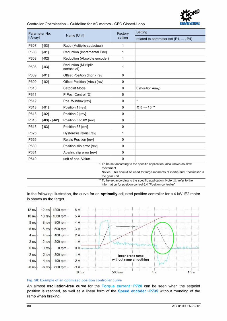
Controller Optimisation – Guideline for AC motors - CFC Closed-Loop
80 AG 0100 EN-3216
Parameter No. [-Array] Name [Unit] Factory
setting Setting
related to parameter set (P1, ... , P4)
P607 [-03] Ratio (Multiplic set/actual) 1
P608 [-01] Reduction (Incremental Enc) 1
P608 [-02] Reduction (Absolute encoder) 1
P608 [-03] Reduction (Multiplic set/actual) 1
P609 [-01] Offset Position (Incr.) [rev] 0
P609 [-02] Offset Position (Abs.) [rev] 0
P610 Setpoint Mode 0 0 (Position Array)
P611 P Pos. Control [%] 5
P612 Pos. Window [rev] 0 *
P613 [-01] Position 1 [rev] 0 0 → 10 **
P613 [-02] Position 2 [rev] 0
P613 [-03] - [-62] Position 3 to 62 [rev] 0
P613 [-63] Position 63 [rev] 0
P625 Hysteresis relais [rev] 1
P626 Relais Position [rev] 0
P630 Position slip error [rev] 0
P631 Abs/Inc slip error [rev] 0
P640 unit of pos. Value 0
* To be set according to the specific application, also known as slow movement Notice: This should be used for large moments of inertia and "backlash" in the gear unit.
** To be set according to the specific application. Note : refer to the
information for position control 6.4 "Position controller"
In the following illustration, the curve for an optimally adjusted position controller for a 4 kW IE2 motor is shown as the target.
Fig. 50: Example of an optimised position controller curve An almost oscillation-free curve for the Torque current ~P720 can be seen when the setpoint position is reached, as well as a linear form of the Speed encoder ~P735 without rounding of the ramp when braking.
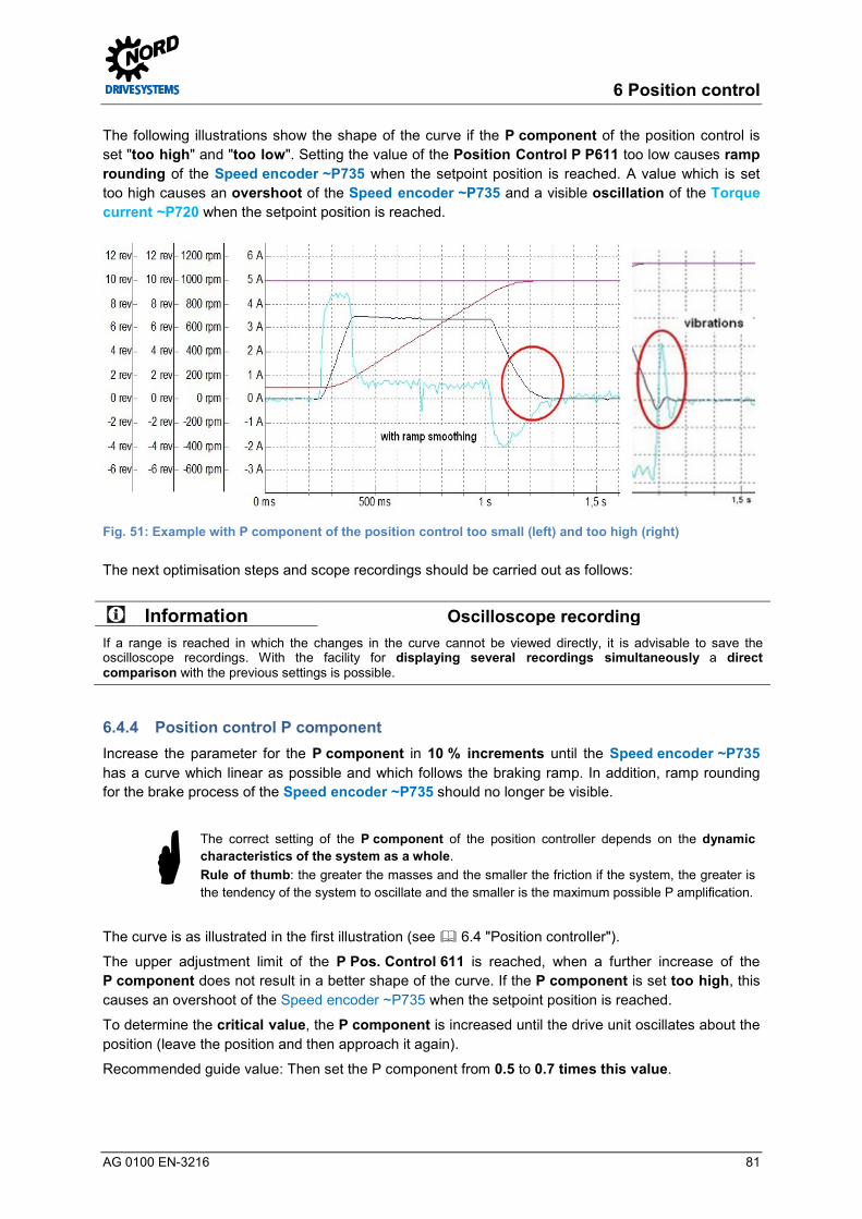
6 Position control
AG 0100 EN-3216 81
The following illustrations show the shape of the curve if the P component of the position control is set "too high" and "too low". Setting the value of the Position Control P P611 too low causes ramp rounding of the Speed encoder ~P735 when the setpoint position is reached. A value which is set too high causes an overshoot of the Speed encoder ~P735 and a visible oscillation of the Torque current ~P720 when the setpoint position is reached.
Fig. 51: Example with P component of the position control too small (left) and too high (right)
The next optimisation steps and scope recordings should be carried out as follows:
Information Oscilloscope recording If a range is reached in which the changes in the curve cannot be viewed directly, it is advisable to save the oscilloscope recordings. With the facility for displaying several recordings simultaneously a direct comparison with the previous settings is possible. Pos: 265 /Appli kati onen/[AG 0100 - AG 0101] allgemei ngültige Modul e/6. Lagereg elungP-Anteil Lag eregler @ 5\mod_1407413320580_388.docx @ 146614 @ 3 @ 1
6.4.4 Position control P component Increase the parameter for the P component in 10 % increments until the Speed encoder ~P735 has a curve which linear as possible and which follows the braking ramp. In addition, ramp rounding for the brake process of the Speed encoder ~P735 should no longer be visible.
The correct setting of the P component of the position controller depends on the dynamic characteristics of the system as a whole. Rule of thumb: the greater the masses and the smaller the friction if the system, the greater is the tendency of the system to oscillate and the smaller is the maximum possible P amplification.
The curve is as illustrated in the first illustration (see 6.4 "Position controller").
The upper adjustment limit of the P Pos. Control 611 is reached, when a further increase of the P component does not result in a better shape of the curve. If the P component is set too high, this causes an overshoot of the Speed encoder ~P735 when the setpoint position is reached.
To determine the critical value, the P component is increased until the drive unit oscillates about the position (leave the position and then approach it again).
Recommended guide value: Then set the P component from 0.5 to 0.7 times this value.
Controller Optimisation – Guideline for AC motors - CFC Closed-Loop
82 AG 0100 EN-3216
For POSICON applications with a subordinate speed control (Servo Mode P300 1 = ON ( CFC closed-loop) use of a setting which deviates from the standard setting of the speed control is usually to be recommended for applications with large masses. For the P component of the speed control a value of 100 to 150% should be set in the parameter Speed Ctrl P P310. As the I component in the parameter Speed Ctrl I P311, a value of between 3 % / ms and 5 % / ms has proved to be effective.
Pos: 266 /Appli kati onen/[AG 0100 - AG 0101] allgemei ngültige Modul e/6. Lagereg elungKriterien @ 5\mod_1404986163580_388.docx @ 140236 @ 3 @ 1
6.4.5 Criteria The following criteria should be noted for optimisation of the field position controller:
The aim is to optimise the curve for the Torque current ~P720 taking the criteria into account, with the "correct" setting of the P component.
• The curve for the Speed encoder ~P735 should be linear and follow the braking ramp • No overshoot of the Speed encoder ~P735 when the setpoint position is reached • No ramp rounding of the Speed encoder ~P735 during braking or in the braking ramp • No oscillation of the Torque current ~P720 should be evident when the setpoint position is
reached
Information Optimisation steps The step widths stated for control optimisation may differ depending on the application. Furthermore, the step widths can be selected even finer for the final optimisation steps. Pos: 267 /Appli kati onen/[AG 0100 - AG 0101] allgemei ngültige Modul e/Allgemei n gül tige Ü berschriften/Opti mi erungsablauf [Ü2] @ 7\mod_1432029832970_388.docx @ 220967 @ 2 @ 1

6 Position control
AG 0100 EN-3216 83
6.5 Optimisation procedure Pos: 268 /Appli kati onen/[AG 0100 - AG 0101] allgemei ngültige Modul e/Str ukturmodul e/H andlungsanweisung @ 7\mod_1434979210308_388.docx @ 227979 @ @ 1
Instructions
Pos : 269 /Appli kati onen/[AG 0100] Regl eropti mier ung ASM - CFC Cl osed-Loop/6. Lager egel ung/Optimi erungsablauf @ 5\mod_1404986160680_388.docx @ 140212 @ @ 1
The following illustrations show the optimisation process for the position controller using the example of a 4.0 kW asynchronous motor with efficiency class IE2 on the basis of individual scope recordings.
Legend Actual position 32bit Low =P601 Speed encoder ~P735
Act. ref. pos. 32bit Low =P602 Torque current ~P720
Step 1. "P" scope recording 2. "P" scope recording
Parameter settings P611 = 5 % P611 = 15 %
Step 3. "P" scope recording 4. "P" scope recording
Parameter settings P611 = 25 % P611 = 35 %
Step 5. "P" scope recording 9. "P" scope recording
Parameter settings P611 = 45 % P611 = 85 %
Fig. 52: Curve for the P component of the position control
Starting point
P component too high
P component
P component P component
P component far too high

Controller Optimisation – Guideline for AC motors - CFC Closed-Loop
84 AG 0100 EN-3216
Pos: 283 /Appli kati onen/[AG 0100] Regl eropti mier ung ASM - CFC Cl osed-Loop/7. Schl upfkompensi erung/Schl upfkompensierung [Ü 1] @ 7\mod_1431931030484_388.docx @ 219975 @ 1 @ 1
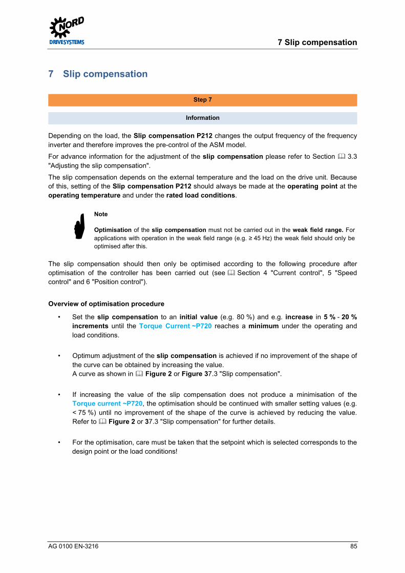
7 Slip compensation
AG 0100 EN-3216 85
7 Slip compensation Pos: 284 /Appli kati onen/[AG 0100 - AG 0101] allgemei ngültige Modul e/Str ukturmodul e/Schrit t 7 @ 7\mod_1434978715730_388.docx @ 227820 @ @ 1
Step 7
Pos : 285 /Appli kati onen/[AG 0100 - AG 0101] allgemei ngültige Modul e/Str ukturmodul e/Infor mation @ 7\mod_1434979005376_388.docx @ 227948 @ @ 1
Information
Pos : 286 /Appli kati onen/[AG 0100] Regl eropti mier ung ASM - CFC Cl osed-Loop/7. Schl upfkompensi erung/Schl upfkompensierung @ 5\mod_1401797741633_388.docx @ 134776 @ 5 @ 1
Depending on the load, the Slip compensation P212 changes the output frequency of the frequency inverter and therefore improves the pre-control of the ASM model.
For advance information for the adjustment of the slip compensation please refer to Section 3.3 "Adjusting the slip compensation".
The slip compensation depends on the external temperature and the load on the drive unit. Because of this, setting of the Slip compensation P212 should always be made at the operating point at the operating temperature and under the rated load conditions.
Note Optimisation of the slip compensation must not be carried out in the weak field range. For applications with operation in the weak field range (e.g. ≥ 45 Hz) the weak field should only be optimised after this.
The slip compensation should then only be optimised according to the following procedure after optimisation of the controller has been carried out (see Section 4 "Current control", 5 "Speed control" and 6 "Position control").
Overview of optimisation procedure
• Set the slip compensation to an initial value (e.g. 80 %) and e.g. increase in 5 % - 20 % increments until the Torque Current ~P720 reaches a minimum under the operating and load conditions.
• Optimum adjustment of the slip compensation is achieved if no improvement of the shape of the curve can be obtained by increasing the value. A curve as shown in Figure 2 or Figure 37.3 "Slip compensation".
• If increasing the value of the slip compensation does not produce a minimisation of the Torque current ~P720, the optimisation should be continued with smaller setting values (e.g. < 75 %) until no improvement of the shape of the curve is achieved by reducing the value. Refer to Figure 2 or 37.3 "Slip compensation" for further details.
• For the optimisation, care must be taken that the setpoint which is selected corresponds to the design point or the load conditions!

Controller Optimisation – Guideline for AC motors - CFC Closed-Loop
86 AG 0100 EN-3216
The objective is to achieve a minimum Torque current ~P720 under nominal load conditions with the "correct" setting of the slip compensation. The practical implementation for optimisation of the slip compensation is described in Section 7.4 "Optimisation procedure".
Pos: 291 /Appli kati onen/[AG 0100 - AG 0101] allgemei ngültige Modul e/Allgemei n gül tige D okumente und Ü berschriften/Weiter e Eins tell ungen [Ü2] @ 7\mod_1432029630965_388.docx @ 220873 @ 2 @ 1
7.1 Further settings Pos: 292 /Appli kati onen/[AG 0100 - AG 0101] allgemei ngültige Modul e/Str ukturmodul e/H andlungsanweisung @ 7\mod_1434979210308_388.docx @ 227979 @ @ 1
Instructions
Pos : 293 /Appli kati onen/[AG 0100] Regl eropti mier ung ASM - CFC Cl osed-Loop/7. Schl upfkompensi erung/Wei ter e Eins tell ungen @ 5\mod_1412068715206_388.docx @ 152094 @ @ 1
For optimisation of the slip compensation, all of the parameters for • the relevant optimisation of the controller (see previous Section ) must be optimised • all other parameters must be set according to the specific requirements for the application.
Information Application information All parameters which are to be set in advance, as well as the setpoint specification (required speed) result from the application requirements. When setting the Acceleration time P102, care must be taken that the frequency inverter does not enter the current limit (Warning C004 = Overcurrent measured).
For applications with operation in the weak field range the weak field controller should always be optimised as the last optimisation step of the weak field controller after optimisation of the slip compensation.
Parameter No. [-Array] Name [Unit] Factory
setting Setting
related to parameter set (P1, ... , P4)
BASIC PARAMETERS
P113 (P) Jog frequency [Hz] 0.0 0.0 40.0
Adjustment of the slip compensation should be carried out using observation of the Torque current =P720) e.g. with the aid of the NORD CON oscilloscope function.
Before starting the scope recording and enabling the drive unit, the setpoint must be set to a value which corresponds to the requirements of the application or the designed operating point. I.e. in this example (frequency inverter 4.0 kW / motor combination 4.0 kW) a setpoint frequency of approx. 40 HZ must be specified.
Pos: 295 /Appli kati onen/[AG 0100 - AG 0101] allgemei ngültige Modul e/Allgemei n gül tige D okumente und Ü berschriften/N ORD CON [Ü 2] @ 7\mod_1432029689942_388.docx @ 220904 @ 2 @ 1
7 Slip compensation
AG 0100 EN-3216 87
7.2 NORD CON Pos: 296 /Appli kati onen/[AG 0100 - AG 0101] allgemei ngültige Modul e/Str ukturmodul e/Infor mation & H andlungsanweisung @ 7\mod_1434981091960_388.docx @ 228011 @ @ 1
Information & instructions
Pos : 297 /Appli kati onen/[AG 0100 - AG 0101] allgemei ngültige Modul e/Allgemei n gül tige D okumente und Ü berschriften/N ORD CON [Kurzfassung] @ 5\mod_1403614918300_388.docx @ 137991 @ @ 1
Further information about the settings can be obtained from Section 4.2 "NORD CON" and the following. Pos: 298 /Appli kati onen/[AG 0100] Regl eropti mier ung ASM - CFC Cl osed-Loop/7. Schl upfkompensi erung/Fernbedi enen @ 5\mod_1412068803899_388.docx @ 152238 @ 3 @ 1
7.2.1 Remote control The following setting must be made in the Remote Control screen to optimise the slip compensation before starting the scope recordings.
Set the setpoint to 80 %, i.e.set the setpoint frequency to 40 Hz
Use the + value or the - value button
Press the OK button to save the frequency as the jog frequency in P113
Press the Enable button
Steps and are not required if a jog frequency has been parameterised.
Fig. 53: Remote control of slip compensation, setpoint and enabling Pos: 300 /Appli kati onen/[AG 0100] Regl eropti mier ung ASM - CFC Cl osed-Loop/7. Schl upfkompensi erung/NORD CON Oszill oskop @ 5\mod_1412068718081_388.docx @ 152166 @ 3 @ 1

Controller Optimisation – Guideline for AC motors - CFC Closed-Loop
88 AG 0100 EN-3216
7.2.2 Oscilloscope The following settings should be made under the two tabs Recording or Channel Settings of the NORD CON Oscilloscope Function before starting the oscilloscope recordings. The settings and graphic displays in the illustrations may differ according to the frequency inverter types, versions and software status.
Set Trigger to Enable
Set the scan rate to 20 ms → Scan duration 4 s → Scan rate depending on the application type which is set Note The scan rate should be selected so that it corresponds to the scope recordings in the illustrations in Section 7.4 "Optimisation procedure"!
Set the start of recording e.g. to 4 sec after the trigger, i.e. for lifting equipment after the acceleration phase and for movement applications during the acceleration phase.
Fig. 54: Oscilloscope settings for trigger and scan rate / scan duration
Fig. 55: Resolution settings for the time axis, comment examples
Fig. 56: Oscilloscope channel settings for the four measurement values
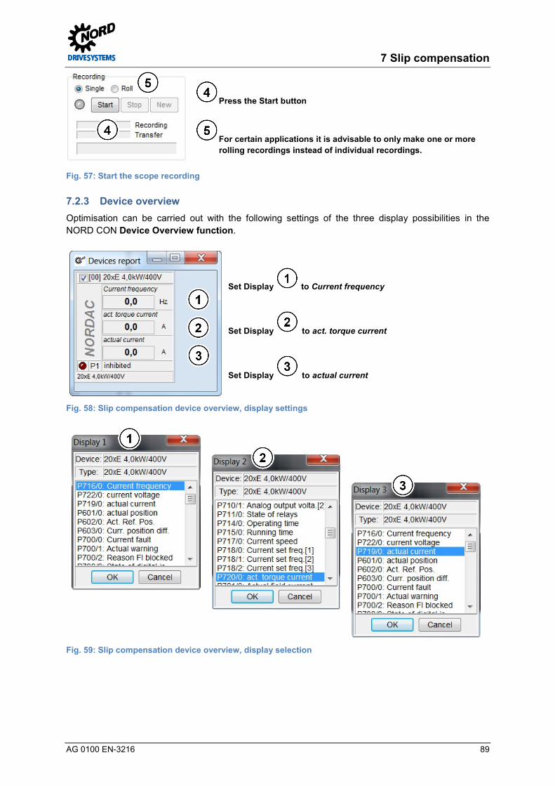
7 Slip compensation
AG 0100 EN-3216 89
Press the Start button
For certain applications it is advisable to only make one or more rolling recordings instead of individual recordings.
Fig. 57: Start the scope recording Pos: 301 /Appli kati onen/[AG 0100] Regl eropti mier ung ASM - CFC Cl osed-Loop/7. Schl upfkompensi erung/Ger äteübersicht @ 6\mod_1413455233174_388.docx @ 155442 @ 3 @ 1
7.2.3 Device overview Optimisation can be carried out with the following settings of the three display possibilities in the NORD CON Device Overview function.
Set Display to Current frequency
Set Display to act. torque current
Set Display to actual current
Fig. 58: Slip compensation device overview, display settings
Fig. 59: Slip compensation device overview, display selection Pos: 303 /Appli kati onen/[AG 0100] Regl eropti mier ung ASM - CFC Cl osed-Loop/7. Schl upfkompensi erung/Schl upfkompensation [Ü 2] @ 7\mod_1432046820271_388.docx @ 221092 @ 2 @ 1

Controller Optimisation – Guideline for AC motors - CFC Closed-Loop
90 AG 0100 EN-3216
7.3 Slip compensation Pos: 305 /Appli kati onen/[AG 0100 - AG 0101] allgemei ngültige Modul e/Str ukturmodul e/Infor mation & H andlungsanweisung @ 7\mod_1434981091960_388.docx @ 228011 @ @ 1
Information & instructions
Pos : 306 /Appli kati onen/[AG 0100] Regl eropti mier ung ASM - CFC Cl osed-Loop/7. Schl upfkompensi erung/Schl upfkompensation @ 5\mod_1412068953450_388.docx @ 152314 @ @ 1
For slip compensation, the slip compensation is changed for the particular optimisation steps.
As the initial for optimisation of the slip compensation, for the 1st optimisation step the slip compensation is set to 80 % in the parameter Slip compensation P212.
Parameter No. [-Array] Name [Unit] Factory
setting Setting
related to parameter set (P1, ... , P4)
MOTOR DATA/ CHARACTERISTIC CURVE PARAMETERS
P212 (P) Slip compensation [%] 100 80 optimal
With constant load, the Slip compensation P212 must be optimised until the Torque current ~P720 is at a minimum.
If the slip compensation is not optimised, this results in a higher current consumption by the drive unit for the same load conditions. Optimisation should always be carried out under nominal load operation and at the designed operating conditions (operating mode, operating temperature, load conditions etc.)!
The following diagram / illustration shows the optimum setting for the Slip compensation P212:
Fig. 60: Diagram for optimum current / slip compensation
The changes to the slip compensation must be checked with the NORD CON Oscilloscope Function ( 4.2 "NORD CON").

7 Slip compensation
AG 0100 EN-3216 91
In the following illustration, the curve for an optimally adjusted slip compensation for a 4.0 kW asynchronous motor with efficiency class IE2 is shown as the target.
Fig. 61: Example of optimised slip compensation
The optimum curve for the Torque current ~P720 at the operating point for a lifting equipment application under nominal load conditions is illustrated.
The following illustrations show the shape of the curve if the slip compensation is set "too high" and "too low". In the case of a lifting equipment application (lifting a load), a value for the Slip compensation P212 which is set too high or too low causes and increased Torque current ~P720 or an increase in the current consumption of the motor.
Fig. 62: Example with the slip compensation set too high (right) and too low (left)
The next optimisation steps and scope recordings should be carried out as follows:
Controller Optimisation – Guideline for AC motors - CFC Closed-Loop
92 AG 0100 EN-3216
Information Oscilloscope recording If a range is reached in which the changes in the curve cannot be viewed directly, it is advisable to save the oscilloscope recordings. With the facility for displaying several recordings simultaneously a direct comparison with the previous settings is possible. Pos: 308 /Appli kati onen/[AG 0100] Regl eropti mier ung ASM - CFC Cl osed-Loop/7. Schl upfkompensi erung/Wer t Schl upfkompensati on @ 5\mod_1412077973773_388.docx @ 152338 @ 3 @ 1
7.3.1 Slip compensation value Increase or decrease the parameter for Slip compensation in e.g. 5 %, 10 % or 20 % increments until the Torque current =P720 during movement applications, or in the case of lifting equipment applications, after the acceleration ramp reaches a minimum.
The curve is as illustrated in the first Illustration ( 7 "Slip compensation").
The optimum setting of the Slip compensation P212 is achieved, when a further increase or decrease of the value does not result in a better shape of the curve (in the sense of the minimum current). A value which is set "too low" or "too high” always causes an increase of the Torque current =P720. Pos: 310 /Appli kati onen/[AG 0100] Regl eropti mier ung ASM - CFC Cl osed-Loop/7. Schl upfkompensi erung/Kriterien @ 5\mod_1412068743081_388.docx @ 152190 @ 3 @ 1
7.3.2 Criteria The following criteria should be noted for optimisation of the slip compensation:
The objective is to achieve a minimum Torque current ~P720 under nominal load conditions with the "correct" setting of the slip compensation.
• For movement applications, the curve for the Torque current ~P720 during, or in the case of lifting equipment application, after the acceleration ramp under nominal load should always reach a minimum
• The curve for the Flux current ≈P721 should also be analysed and should not show any abnormalities
Information Optimisation steps The increments stated for slip optimisation may differ depending on the application. Furthermore, the increments can be selected even finer for the final optimisation steps. Pos: 312 /Appli kati onen/[AG 0100 - AG 0101] allgemei ngültige Modul e/Allgemei n gül tige D okumente und Ü berschriften/Opti mi erungsablauf [Ü 2] @ 7\mod_1432029832970_388.docx @ 220967 @ 2 @ 1
7.4 Optimisation procedure Pos: 313 /Appli kati onen/[AG 0100 - AG 0101] allgemei ngültige Modul e/Str ukturmodul e/H andlungsanweisung @ 7\mod_1434979210308_388.docx @ 227979 @ @ 1
Instructions
Pos : 314 /Appli kati onen/[AG 0100] Regl eropti mier ung ASM - CFC Cl osed-Loop/7. Schl upfkompensi erung/Opti mi erungsablauf @ 5\mod_1412068743695_388.docx @ 152214 @ @ 1
The following illustrations show the optimisation process for the slip compensation using the example of a 4.0 kW asynchronous motor with efficiency class IE2 on the basis of individual scope recordings.

7 Slip compensation
AG 0100 EN-3216 93
Legend Set. freq after freq. ramp ~P718[02] Speed encoder ~P735
Torque current ~P720 Actual current =P719
Step 1. Scope recording 2. Scope recording
Parameter settings P212 = 80 % P212 = 100 %
Step 3. Scope recording 4. Scope recording
Parameter settings P212 = 120 % P212 = 60 %
Step 5. Scope recording 6. Scope recording
Parameter settings P212 = 90 % P212 = 95 %
Fig. 63: Slip compensation curve Pos: 317 /Appli kati onen/[AG 0100 - AG 0101] allgemei ngültige Modul e/8. Fel dschwächeregel ung/Fel dschwächeregel ung [Ü 1] @ 7\mod_1431931064441_388.docx @ 220006 @ 1 @ 1
Starting point Value
Value
Value far too small Value far too high
Value
Controller Optimisation – Guideline for AC motors - CFC Closed-Loop
94 AG 0100 EN-3216
8 Weak field controller Pos: 319 /Appli kati onen/[AG 0100 - AG 0101] allgemei ngültige Modul e/Str ukturmodul e/Schrit t 8 @ 7\mod_1434978719982_388.docx @ 227852 @ @ 1
Step 8
Pos : 320 /Appli kati onen/[AG 0100 - AG 0101] allgemei ngültige Modul e/Str ukturmodul e/Infor mation @ 7\mod_1434979005376_388.docx @ 227948 @ @ 1
Information
Pos : 321 /Appli kati onen/[AG 0100] Regl eropti mier ung ASM - CFC Cl osed-Loop/8. Feldschwächer egelung/Feldschwächer egelung @ 5\mod_1402039383531_388.docx @ 136270 @ 5 @ 1
The weak field controller is a PI controller and comprises the following three parameters.
• Weak field controller (P318, P319, P320)
The parameter P-Weak P318 is for the P component. The parameter I-Weak P319 must be used for the I component. In addition the "limiting parameter” Weak Border P320 completes the weak field controller. This parameter is used to specify the speed / voltage range in which the controller weakens the field.
Information Weak field range The weak field range depends on several factors. These include the:
• Mains voltage • Motor (type and power) • Frequency inverter (type and size) • Load
For the SK 200E frequency inverter / motor combination (4.0 kW) and the supply voltage of 400 V (50 Hz) described in this guide, the weak field range begins at about ≥ 45 Hz.
IE4 motors should not be operated in the weak field range!
Field weakening is performed if the voltage can no longer increase proportionally to the speed. In this case the maximum output voltage is reached and the Voltage components Ud and Uq are limited. Due to the limitation of the Voltage component Usd ~P723 or the parameter Voltage -d P723 the field is weakened. The weak field control is only effective in the weak field range.
The behaviour of the system in the transition to the weak field range is less favourable than vice versa, because of which the optimisation must be made when the speed is increased.
The following diagrams show several control curves / transient responses which occur after a sudden change of the setpoint for various weak field controllers. Only the various aspects for optimisation of the Flux current ≈P721 are illustrated.

8 Weak field controller
AG 0100 EN-3216 95
Diagram 1
Selected P component too small
Diagram 2
P component optimised and I component selected too small
Diagram 3
P and I component optimal
Diagram 4
P component optimised and I component selected too large
Fig. 64: Control value curves
The various control curves, where the setpoint is shown in RED and the actual value is shown in GREEN, describe the dynamic curve for the transient response, which is set via the individual control parameters (P and I component) of the controller.
In the diagrams above, the curves for the control values are shown with short acceleration ramps (short acceleration times). For longer acceleration times, the curves for the magnetisation current deviate as shown in Diagram 5. No curves with severely reducing and then increasing amplitude of the magnetisation current occur.
Diagram 5
Optimum selection of the P and I component for long acceleration time
Fig. 65: Control value curves with long acceleration ramp

Controller Optimisation – Guideline for AC motors - CFC Closed-Loop
96 AG 0100 EN-3216
It is recommended that the following optimisation steps are performed to systematically adjust the weak field controller (PI controller):
Overview of optimisation procedure
• Set the I component to a low value
• Set the P component to a small value and increase it e.g. in 50% increments until both the Flux current ≈P721 and the curve for the Torque current ≈P720 in the weak field range have a curve which is as free from oscillations as possible.
• Optimum adjustment of the P component is achieved if no improvement of the shape of the curve can be obtained by increasing the value. A curve as shown in Diagram 2 results.
• This is followed by an increase in the I component in order to further improve the curve according to the stated criteria. Diagram 3 shows the optimised curve, whereby in this diagram, the brief overshoot is slightly exaggerated for clarity. The permissible slight overshoot is caused by the acceleration time which is selected and set.
• If the I component is set too large, this can be seen from the oscillations in the Flux current ≈P721 in Diagram 4. In this case, the I component must be reduced again.
• For the optimisation, the setpoint which is selected for the weak field range must also be taken into account!
Diagram 1 shows the curve if the P components is selected too small. In contrast, Diagram 5 shows the curve for the actual value with an optimally adjusted P and I component with a long acceleration phase. For shorter acceleration phases, the curve shown in Diagram 3 deviates from the curve in Diagram 5 (no overshoot) for the Flux current ≈P721.
The aim is to obtain a curve which as optimal as possible, or which corresponds to the curves for the Flux current ≈P721 as shown in Diagrams 3 and 5, with the "correct" setting for the I and P components. A slight overshoot of the Flux current ≈P721 after the setpoint is reached, with a subsequent linear and oscillation-free curve is permissible for short acceleration phases. The practical implementation for optimisation of a weak field controller is described in Section 8.4 "Optimisation procedure".
Pos: 322 /Appli kati onen/[AG 0100 - AG 0101] allgemei ngültige Modul e/Allgemei n gül tige D okumente und Ü berschriften/Weiter e Eins tell ungen [Ü2] @ 7\mod_1432029630965_388.docx @ 220873 @ 2 @ 1

8 Weak field controller
AG 0100 EN-3216 97
8.1 Further settings Pos: 323 /Appli kati onen/[AG 0100 - AG 0101] allgemei ngültige Modul e/Str ukturmodul e/H andlungsanweisung @ 7\mod_1434979210308_388.docx @ 227979 @ @ 1
Instructions
Pos : 324 /Appli kati onen/[AG 0100] Regl eropti mier ung ASM - CFC Cl osed-Loop/8. Feldschwächer egelung/Wei ter e Ei nstellungen @ 5\mod_1403694560040_388.docx @ 138267 @ @ 1
For optimisation of the weak field controller, it is essential that the following two parameters are set in advance.
Parameter No. [-Array] Name [Unit] Factory
setting Setting
related to parameter set (P1, ... , P4)
BASIC PARAMETERS
P102 (P) Acceleration time [s] 2.0 2.0 → 0.3 *
P105 (P) Maximum frequency [Hz] 50.0 / (60.0) 50.0 → 100.0 **
P113 (P) Jog frequency [Hz] 0.0 0.0 → 75.0
* To be set according to the specific application (Notice: in this example
without load)
** Note: For testing double the nominal frequency of the motor (see P201)
The ramp time and the maximum frequency must be set under the "Basic Parameters" tab in the parameter Acceleration time P102 and Maximum frequency P105.
Information Application information The ramp times for the Acceleration time P102, the Maximum frequency P105 and the setpoint specification (required speed) result from the requirements of the application. When setting the Acceleration time P102, care must be taken that the frequency inverter does not enter the current limit (Warning C004 = Overcurrent measured).
Information Setpoint / Weak field range The specified setpoint and the specified Maximum frequency P105 should correspond to the design range (50 Hz / 87 Hz / 100 Hz – characteristic curves).
A setting value which corresponds to the requirements of the application should be selected for the Maximum frequency P105 for optimisation of the weak field controller
The weak field range for this application therefore begins above approx 45 Hz and ends at approx. 100 Hz.
The setting for the Acceleration time P102 must be selected so that if possible, 50 % - 100 % of the nominal motor current (see type plate / Nominal current P203) is achieved with the optimisation.
Setting of the Torque current ≈P720 (Isq) and the Flux current ≈P721 (Isd) should be made with the aid of the NORD CON oscilloscope function.
Before starting the scope recording and enabling the drive unit, the setpoint must be set to a value of e.g. 75 % (with a Maximum frequency P105 of 100 Hz). I.e. in this example (4.0 kW frequency inverter / motor combination) a setpoint frequency of 75 Hz must be specified.

Controller Optimisation – Guideline for AC motors - CFC Closed-Loop
98 AG 0100 EN-3216
Information Optimisation information To optimise the weak field controller, the Maximum frequency P105 should be set according to the specific application or the requirements of the application. If this is not defined, for a "pre optimisation"* the maximum frequency should be set to 2x the Nominal frequency P201!
I.e. for applications with an extended operating point (e.g. 100 Hz characteristic curve) a Maximum frequency P105 of 200 Hz should be set. The setpoint (frequency) which is to be set should then be e.g. 75 % ≈ 150 Hz.
The weak field range for this application therefore begins above approx. 45 Hz and ends at approx. 200 Hz. Pos: 325 /Appli kati onen/[AG 0100 - AG 0101] allgemei ngültige Modul e/Allgemei n gül tige D okumente und Ü berschriften/N ORD CON [Ü 2] @ 7\mod_1432029689942_388.docx @ 220904 @ 2 @ 1

8 Weak field controller
AG 0100 EN-3216 99
8.2 NORD CON Pos: 326 /Appli kati onen/[AG 0100 - AG 0101] allgemei ngültige Modul e/Str ukturmodul e/Infor mation & H andlungsanweisung @ 7\mod_1434981091960_388.docx @ 228011 @ @ 1
Information & instructions
Pos : 327 /Appli kati onen/[AG 0100 - AG 0101] allgemei ngültige Modul e/Allgemei n gül tige D okumente und Ü berschriften/N ORD CON [Kurzfassung] @ 5\mod_1403614918300_388.docx @ 137991 @ @ 1
Further information about the settings can be obtained from Section 5.2 "NORD CON" and the following. Pos: 328 /Appli kati onen/[AG 0100] Regl eropti mier ung ASM - CFC Cl osed-Loop/8. Feldschwächer egelung/Fernbedienen @ 5\mod_1403694561693_388.docx @ 138315 @ 3 @ 1
8.2.1 Remote control The following setting must be made in the Remote Control screen to optimise the weak field controller before starting the scope recordings.
Set the setpoint to 75 %, i.e.set the setpoint frequency to 75 Hz
Use the + value or the - value button
Press the OK button to save the frequency as the jog frequency in P113
Press the Enable button
Steps and are not required if a jog frequency has been parameterised.
Fig. 66: Remote control of the weak field control, setpoint and enabling Pos: 329 /Appli kati onen/[AG 0100] Regl eropti mier ung ASM - CFC Cl osed-Loop/8. Feldschwächer egelung/Oszilloskop @ 5\mod_1403694562832_388.docx @ 138339 @ 3 @ 1
8.2.2 Oscilloscope The following settings should be made under the two tabs Recording or Channel Settings of the NORD CON Oscilloscope Function before starting the oscilloscope recordings. The settings and graphic displays in the illustrations may differ according to the frequency inverter types, versions and software status.

Controller Optimisation – Guideline for AC motors - CFC Closed-Loop
100 AG 0100 EN-3216
Set Trigger to Enable
Set the scan rate to 10 ms → Scan duration 2 s → Scan rate depending on the run up time which is set Note The scan rate should be selected so that it corresponds to the scope recordings in the illustrations in Section 8.4 "Optimisation procedure"!
Fig. 67: Oscilloscope settings for trigger and scan rate / scan duration
Fig. 68: Resolution settings for the time axis, comment examples
Fig. 69: Oscilloscope channel settings for the four measurement values
Press the Start button
Fig. 70: Start the scope recording Pos: 330 /Appli kati onen/[AG 0100 - AG 0101] allgemei ngültige Modul e/8. Fel dschwächeregel ung/Fel dschwächeregler [Ü2] @ 7\mod_1432196931474_388.docx @ 221168 @ 2 @ 1

8 Weak field controller
AG 0100 EN-3216 101
8.3 Weak field controller Pos: 331 /Appli kati onen/[AG 0100 - AG 0101] allgemei ngültige Modul e/Str ukturmodul e/Infor mation & H andlungsanweisung @ 7\mod_1434981091960_388.docx @ 228011 @ @ 1
Information & instructions
Pos : 332 /Appli kati onen/[AG 0100] Regl eropti mier ung ASM - CFC Cl osed-Loop/8. Feldschwächer egelung/Feldschwächer egler @ 5\mod_1403694564065_388.docx @ 138363 @ @ 1
For the weak field controller, the P and I component must be changed for the relevant optimisation steps.
As the initial for optimisation of the weak field controller, for the 1st optimisation step the P component (P318) should be set to 50 % and the I component (P319) should be set to 5 % / ms.
Parameter No. [-Array] Name [Unit] Factory
setting Setting
related to parameter set (P1, ... , P4)
Speed control
P318 (P) P-Weak [%] 150 150 → 50
P319 (P) I-Weak [%/ms] 20 20 → 5
The changes to the control parameters must be checked with the NORD CON Oscilloscope Function ( 8.2.2 "Oscilloscope").
Information Acceleration time With large acceleration times, a linearisation of the two currents in the weak field range due to the setting of the weak field controller is clearly apparent. For small run up times, true linearisation of the curves is not possible. Because of this, in this case the oscillations of the current curves recorded with the oscilloscope should be reduced by optimisation of the weak field control parameters.
In the following illustration, the curve for an optimally adjusted position controller for a 4 kW IE2 asynchronous motor is shown as the target.
Fig. 71: Example of an optimised weak field controller curve
An almost oscillation-free curve for the Flux current ≈P721 in the weak field range (> 45 Hz) can be seen, with an overshoot after the setpoint has been reached as well as a linear increase of the Speed encoder ~P735.

Controller Optimisation – Guideline for AC motors - CFC Closed-Loop
102 AG 0100 EN-3216
In addition, the influence of the Flux delay P558 at the start of the scope recording.
The following illustration shows the form of the curve of the I component of the weak field control is set too high. After the setpoint has been reached, the value of the I-Weak P319 which is set too high causes oscillation of the Flux current ≈P721 and the Torque current ≈P720.
Fig. 72: Example with an excessive I component of the weak field controller
The next optimisation steps and oscilloscope recordings should be carried out as follows:
Information Oscilloscope recording If a range is reached in which the changes in the curve cannot be viewed directly, it is advisable to save the oscilloscope recordings. With the facility for displaying several recordings simultaneously a direct comparison with the previous settings is possible. Pos: 333 /Appli kati onen/[AG 0100] Regl eropti mier ung ASM - CFC Cl osed-Loop/8. Feldschwächer egelung/P- Anteil Fel dschwächeregler @ 5\mod_1403694565109_388.docx @ 138387 @ 3 @ 1
8.3.1 P component of the weak field controller Increase the parameter for the P component in 50 % increments until, if possible, from the start of the weak field range (> 45 Hz) the Flux current ≈P721 initially has a steeply reducing curve which rises steeply again shortly before the setpoint is reached.
The curve is as illustrated in Diagram 2 (see 8 "Weak field controller").
The upper adjustment limit of the P-Weak P318 is reached, when a further increase of the P component does not result in a better shape of the curve (in the sense of a "low oscillation" current curve). A value of the P component which is set "too high does not have any further effect on the Flux current ≈P721.
If the P component for a selected speed (setpoint specification) is set too high, this is not visible in the curve for the Flux current ≈P721 in the transition to the weak field range and after the setpoint has been reached. However, it may be apparent due to an associated noise.
As a guide value the optimised P component of the weak field control should be in the range from 200 % to 250 %. Pos: 334 /Appli kati onen/[AG 0100] Regl eropti mier ung ASM - CFC Cl osed-Loop/8. Feldschwächer egelung/I- Anteil Feldschwächer egler @ 5\mod_1403694565988_388.docx @ 138411 @ 3 @ 1
8 Weak field controller
AG 0100 EN-3216 103
8.3.2 I component of the weak field control Beginning from the set starting value [5 % / ms] increase the I component in small increments (e.g. 5 % / ms) until an approximately oscillation-free curve for the Flux current ≈P721 no longer results. After the setpoint has been reached, there should only be a single overshoot of the Flux current ≈P721 after which there should be a linear and oscillation-free curve.
The curve is as illustrated in Diagram 3 or Diagram 5 see 8 "Weak field controller".
The upper adjustment limit of the I-Weak P319 is reached, when a further increase of the I component results in further oscillations in the Flux current ≈P721 curve. In this case, the I component must be reduced again.
An I component which is set "too high" may cause oscillations of the Torque current ≈P720 after the setpoint has been reached.
If the I component for a selected speed (setpoint specification) is set too high, this is apparent from the oscillation of the Flux current ≈P721 in the transition to the weak field range and after the setpoint has been reached and possible by the associated production of noise.
Pos: 335 /Appli kati onen/[AG 0100] Regl eropti mier ung ASM - CFC Cl osed-Loop/8. Feldschwächer egelung/Kriterien @ 5\mod_1404208517992_388.docx @ 139606 @ 3 @ 1
8.3.3 Criteria The following criteria should be noted for optimisation of the weak field control:
The aim is to optimise the curve for the Flux current ≈P721 with the "correct" settings of the P and I components:
• In the weak field range, a clear increase in thes Torque current ≈P720 and a corresponding reduction of the Flux current ≈P721 should be evident
• The curve for the Flux current ≈P721 during the acceleration phase should correspond to Diagram 3 or Diagram 5 ( 8 "Weak field controller"), depending on the acceleration time
• Oscillation-free curve for the Torque current ≈P720 and Flux current ≈P721 in the weak field range after reaching the setpoint value, i.e. only slight oscillations in the two current curves after the acceleration phase; undesirable oscillations are shown in Diagram 4
• No "noise production" in the transition to the weak field range when the drive unit is in operation (if necessary, reduce the P component).
Information Optimisation steps The step widths stated for control optimisation may differ depending on the application. Furthermore, the step widths can be selected even finer for the final optimisation steps. Pos: 336 /Appli kati onen/[AG 0100 - AG 0101] allgemei ngültige Modul e/Allgemei n gül tige D okumente und Ü berschriften/Opti mi erungsablauf [Ü 2] @ 7\mod_1432029832970_388.docx @ 220967 @ 2 @ 1
8.4 Optimisation procedure Pos: 337 /Appli kati onen/[AG 0100 - AG 0101] allgemei ngültige Modul e/Str ukturmodul e/H andlungsanweisung @ 7\mod_1434979210308_388.docx @ 227979 @ @ 1
Instructions
Pos : 364 /Appli kati onen/[AG 0100 - AG 0101] allgemei ngültige Modul e/9. Parameterlisten/Par ameterlisten [Ü 1] @ 7\mod_1431931140490_388.docx @ 220037 @ 1 @ 1
The following illustrations show the optimisation process for the weak field controller using the example of a 4.0 kW asynchronous motor with efficiency class IE2 on the basis of individual scope recordings.
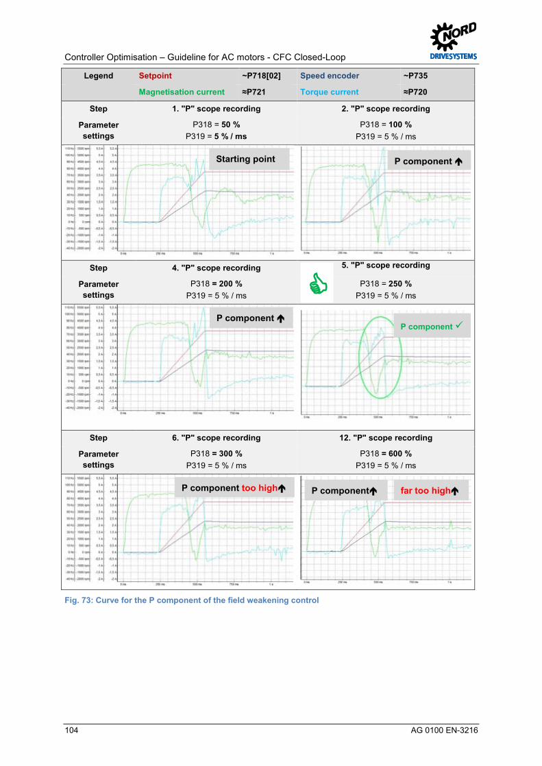
Controller Optimisation – Guideline for AC motors - CFC Closed-Loop
104 AG 0100 EN-3216
Legend Setpoint ~P718[02] Speed encoder ~P735
Magnetisation current ≈P721 Torque current ≈P720
Step 1. "P" scope recording 2. "P" scope recording
Parameter settings
P318 = 50 % P319 = 5 % / ms
P318 = 100 % P319 = 5 % / ms
Step 4. "P" scope recording 5. "P" scope recording
Parameter settings
P318 = 200 % P319 = 5 % / ms
P318 = 250 % P319 = 5 % / ms
Step 6. "P" scope recording 12. "P" scope recording
Parameter settings
P318 = 300 % P319 = 5 % / ms
P318 = 600 % P319 = 5 % / ms
Fig. 73: Curve for the P component of the field weakening control
Starting point P component
P component P component
P component too high far too high P component

8 Weak field controller
AG 0100 EN-3216 105
Legend Setpoint ~P718[02] Speed encoder ~P735
Magnetisation current ≈P721 Torque current ≈P720
Step 1. "I" scope recording 2. "I" scope recording
Parameter settings
P318 = 250 % P319 = 5 % / ms
P318 = 250 % P319 = 10 % / ms
Step 3. "I" scope recording 6. "I" scope recording
Parameter settings
P318 = 250 % P319 = 15 % / ms
P318 = 250 % P319 = 30 % / ms
The following "I" scope recordings are made with a larger acceleration time (1.2 sec).
Step 1. "I" scope recording 2. "I" scope recording
Parameter settings
P318 = 350 % P319 = 10 % / ms
P318 = 350 % P319 = 20 % / ms
Fig. 74: Curve for the I component of the weak field control
I component Starting point
I component I component
too high far too high
I component too high I component

Controller Optimisation – Guideline for AC motors - CFC Closed-Loop
106 AG 0100 EN-3216
9 Parameter lists Pos: 365 /Appli kati onen/[AG 0100 - AG 0101] allgemei ngültige Modul e/Str ukturmodul e/Infor mation @ 7\mod_1434979005376_388.docx @ 227948 @ @ 1
Information
Pos : 366 /Appli kati onen/[AG 0100 - AG 0101] allgemei ngültige Modul e/3. Grundinbetriebnahme/Grundinbetriebnahme [Ü1] @ 7\mod_1431930880787_388.docx @ 219851 @ 2 @ 1
9.1 Basic Commissioning Pos: 367 /Appli kati onen/[AG 0100] Regl eropti mier ung ASM - CFC Cl osed-Loop/9. Parameterlisten/Parametrier ung Grundi nbetriebnahme @ 9\mod_1446541954605_388.docx @ 260619 @ @ 1
Fig. 75: Parameter list for basic commissioning

9 Parameter lists
AG 0100 EN-3216 107
Pos: 370 /Appli kati onen/[AG 0100 - AG 0101] allgemei ngültige Modul e/4. Str omregel ung/Str omregel ung [Ü1] @ 7\mod_1431930921610_388.docx @ 219882 @ 2 @ 1
9.2 Current control Pos: 371 /Appli kati onen/[AG 0100] Regl eropti mier ung ASM - CFC Cl osed-Loop/9. Parameterlisten/Parametrier ung Str omregel ung @ 9\mod_1446541752188_388.docx @ 260355 @ @ 1
Fig. 76: Parameter list for optimised current control Pos: 374 /Appli kati onen/[AG 0100 - AG 0101] allgemei ngültige Modul e/5. Drehzahlreg elung/Drehzahlreg elung [Ü 1] @ 7\mod_1431930963044_388.docx @ 219913 @ 2 @ 1

Controller Optimisation – Guideline for AC motors - CFC Closed-Loop
108 AG 0100 EN-3216
9.3 Speed control Pos: 375 /Appli kati onen/[AG 0100] Regl eropti mier ung ASM - CFC Cl osed-Loop/9. Parameterlisten/Parametrier ung Dr ehzahlregel ung @ 9\mod_1446541936587_388.docx @ 260487 @ @ 1
Fig. 77: Parameter list for optimised current and speed control Pos: 378 /Appli kati onen/[AG 0100 - AG 0101] allgemei ngültige Modul e/6. Lagereg elung/Lager egelung [Ü 1] @ 7\mod_1431931000798_388.docx @ 219944 @ 2 @ 1
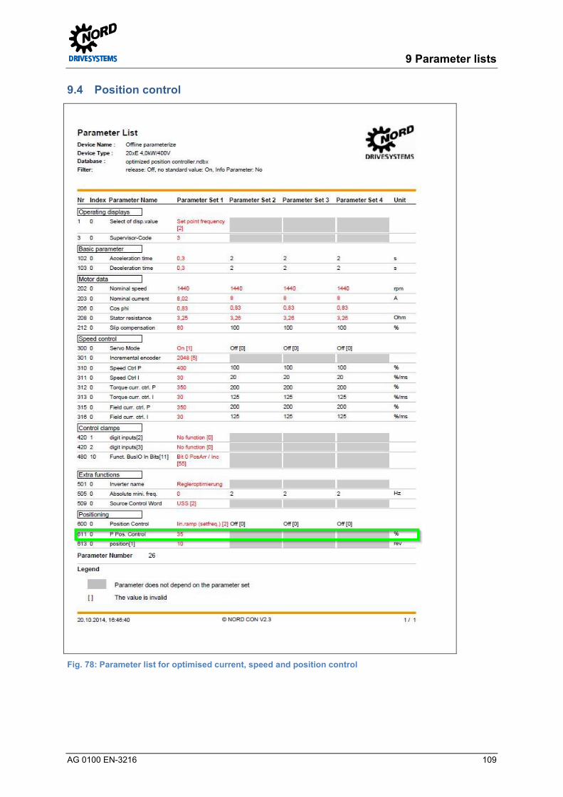
9 Parameter lists
AG 0100 EN-3216 109
9.4 Position control Pos: 379 /Appli kati onen/[AG 0100] Regl eropti mier ung ASM - CFC Cl osed-Loop/9. Parameterlisten/Parametrier ung Lagereg elung @ 9\mod_1446541942393_388.docx @ 260520 @ @ 1
Fig. 78: Parameter list for optimised current, speed and position control Pos: 382 /Appli kati onen/[AG 0100] Regl eropti mier ung ASM - CFC Cl osed-Loop/7. Schl upfkompensi erung/Schl upfkompensierung [Ü 1] @ 7\mod_1431931030484_388.docx @ 219975 @ 2 @ 1

Controller Optimisation – Guideline for AC motors - CFC Closed-Loop
110 AG 0100 EN-3216
9.5 Slip compensation Pos: 383 /Appli kati onen/[AG 0100] Regl eropti mier ung ASM - CFC Cl osed-Loop/9. Parameterlisten/Parametrier ung Schlupfkompensier ung @ 9\mod_1446541949904_388.docx @ 260586 @ @ 1
Fig. 79: Parameter list for optimised current, speed, position control and slip compensation Pos: 384 /Appli kati onen/[AG 0100] Regl eropti mier ung ASM - CFC Cl osed-Loop/8. Feldschwächer egelung/Feldschwächer egelung [Ü 1] @ 9\mod_1446537205079_388.docx @ 260259 @ 2 @ 1

9 Parameter lists
AG 0100 EN-3216 111
9.6 Weak field control Pos: 385 /Appli kati onen/[AG 0100] Regl eropti mier ung ASM - CFC Cl osed-Loop/9. Parameterlisten/Parametrier ung Fel dschwächeregel ung @ 9\mod_1446541945152_388.docx @ 260553 @ @ 1
Fig. 80: Parameter list for all optimised controllers, plus weak field controller Pos: 394 /Appli kati onen/[AG 0100 - AG 0101] allgemei ngültige Modul e/10. Weiter führende D okumentati onen/Weiterführende D okumentati onen [Ü 1] @ 7\mod_1431931215056_388.docx @ 220068 @ 1 @ 1

Controller Optimisation – Guideline for AC motors - CFC Closed-Loop
112 AG 0100 EN-3216
10 Further documentation Pos: 395 /Appli kati onen/[AG 0100 - AG 0101] allgemei ngültige Modul e/Str ukturmodul e/Infor mation @ 7\mod_1434979005376_388.docx @ 227948 @ @ 1
Information
Pos : 396 /Appli kati onen/[AG 0100 - AG 0101] allgemei ngültige Modul e/10. Weiter führende D okumentati onenWeiterführ ende D okumentationen @ 5\mod_1409831513379_388.docx @ 148844 @ @ 1
In case of queries and for further information regarding this document, please contact Electronics Support at Getriebebau NORD GmbH & Co. KG.
On request, further information which is required, e.g. technical data sheets which are not available under www.nord.com - Documentation can be made available to users after technical consultation. Pos: 397 /Appli kati onen/[AG 0100 - AG 0101] allgemei ngültige Modul e/Allgemei n gül tige D okumente und Ü berschriften/H andbücher [Ü 2] @ 7\mod_1432802110860_388.docx @ 221588 @ 2 @ 1
10.1 Manuals Pos: 398 /Appli kati onen/[AG 0100 - AG 0101] allgemei ngültige Modul e/10. Weiter führende D okumentati onenHandbücher @ 5\mod_1400504649959_388.docx @ 132890 @ @ 1
Document Name
BU 0000 NORD CON Software Manual (the Help function of the software should preferably be used) BU 0200 SK 200E – Manual BU 0210 POSICON for SK 200E - Manual BU 0500 SK 5xxE – Manual (SK 500E ... SK 535E) BU 0505 SK 54xE – Manual (SK 540E ... SK 545E) BU 0510 POSICON for SK 500E – Position Control Manual ≥ SK 530E
Table 7: Manuals Pos: 401 /Appli kati onen/[AG 0100 - AG 0101] allgemei ngültige Modul e/10. Weiter führende D okumentati onen/Technische Infor mationen / D atenblätter [Ü 2] @ 7\mod_1432198181354_388.docx @ 221199 @ 2 @ 1
10.2 Technical Information / Data Sheets Pos: 404 /Appli kati onen/[AG 0100 - AG 0101] allgemei ngültige Modul e/Allgemei n gül tige D okumente und Ü berschriften/TIs - Inkr ementaldr ehg eber (IG) [Ü 2] @ 7\mod_1433921190380_388.docx @ 223713 @ 3 @ 1
10.2.1 TIs – Incremental encoder (IG) Pos: 405 /Appli kati onen/[AG 0100 - AG 0101] allgemei ngültige Modul e/10. Weiter führende D okumentati onenTIs - Inkr ementaldr ehg eber (IG) @ 5\mod_1400504651216_388.docx @ 132914 @ @ 1
Document Name Supplier / Type Part No. Data sheet
Enquiries to Service
Incremental encoder IG4 4096, TTL, 5 V, 1.5 m
Fritz Kübler GmbH 8.5820.0H10.xxxx.5093.xxxx
19551020 A0828_5_8.5820.0H10.XXXX.5093.XXXX.pd
Enquiries to Service
Incremental encoder IG41 4096, TTL, 10 - 30 V, 1.5 m
Fritz Kübler GmbH 8.5820.0H30.xxxx.5093.xxxx
19551021 A1495_1_8.5820.0H30.XXXX.5093.XXXX.pd
Enquiries to Service
Incremental encoder IG42 4096, HTL, 10 - 30 V, 1.5 m
Fritz Kübler GmbH 8.5820.0H40.xxxx.5093.xxxx
19551022 A1451_0_8.5820.0H40.XXXX.5093.XXXX.pd
Table 8: TIs – Incremental encoder (IG) Pos: 406 /Appli kati onen/[AG 0100 - AG 0101] allgemei ngültige Modul e/Allgemei n gül tige D okumente und Ü berschriften/TIs - C ANopen Absol utwertdrehgeber ( AG) [Ü2] @ 7\mod_1433921203002_388.docx @ 223745 @ 3 @ 1
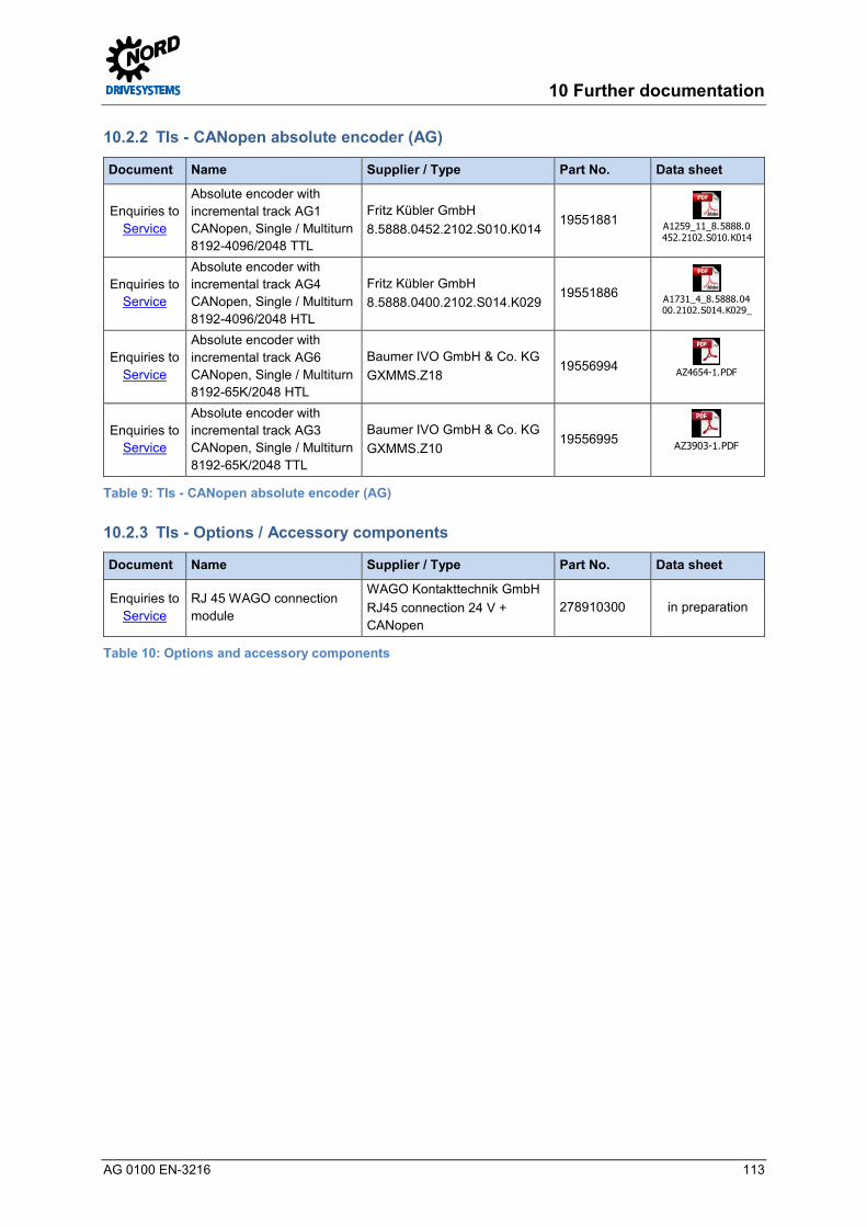
10 Further documentation
AG 0100 EN-3216 113
10.2.2 TIs - CANopen absolute encoder (AG) Pos: 407 /Appli kati onen/[AG 0100 - AG 0101] allgemei ngültige Modul e/10. Weiter führende D okumentati onen/TIs - C ANopen Absol utwertdrehgeber ( AG) @ 7\mod_1432198710739_388.docx @ 221230 @ @ 1
Document Name Supplier / Type Part No. Data sheet
Enquiries to Service
Absolute encoder with incremental track AG1 CANopen, Single / Multiturn 8192-4096/2048 TTL
Fritz Kübler GmbH 8.5888.0452.2102.S010.K014
19551881 A1259_11_8.5888.0452.2102.S010.K014_
Enquiries to Service
Absolute encoder with incremental track AG4 CANopen, Single / Multiturn 8192-4096/2048 HTL
Fritz Kübler GmbH 8.5888.0400.2102.S014.K029
19551886 A1731_4_8.5888.0400.2102.S014.K029_d
Enquiries to Service
Absolute encoder with incremental track AG6 CANopen, Single / Multiturn 8192-65K/2048 HTL
Baumer IVO GmbH & Co. KG GXMMS.Z18
19556994 AZ4654-1.PDF
Enquiries to Service
Absolute encoder with incremental track AG3 CANopen, Single / Multiturn 8192-65K/2048 TTL
Baumer IVO GmbH & Co. KG GXMMS.Z10
19556995 AZ3903-1.PDF
Table 9: TIs - CANopen absolute encoder (AG) Pos: 408 /Appli kati onen/[AG 0100 - AG 0101] allgemei ngültige Modul e/Allgemei n gül tige D okumente und Ü berschriften/TIs - Opti onen / Zubehör komponenten [Ü 2] @ 7\mod_1433921126973_388.docx @ 223682 @ 3 @ 1
10.2.3 TIs - Options / Accessory components Pos: 409 /Appli kati onen/[AG 0100 - AG 0101] allgemei ngültige Modul e/10. Weiter führende D okumentati onen/TIs - Opti onen und Zubehör komponenten @ 7\mod_1432198719371_388.docx @ 221262 @ @ 1
Document Name Supplier / Type Part No. Data sheet
Enquiries to Service
RJ 45 WAGO connection module
WAGO Kontakttechnik GmbH RJ45 connection 24 V + CANopen
278910300 in preparation
Table 10: Options and accessory components Pos: 412 /Appli kati onen/[AG 0100 - AG 0101] allgemei ngültige Modul e/Allgemei n gül tige D okumente und Ü berschriften/Anhang @ 7\mod_1433917553864_388.docx @ 223558 @ 1 @ 1

Controller Optimisation – Guideline for AC motors - CFC Closed-Loop
114 AG 0100 EN-3216
11 Appendix Pos: 413 /Appli kati onen/[AG 0100 - AG 0101] allgemei ngültige Modul e/Allgemei n gül tige D okumente und Ü berschriften/Abkürzung en [Ü2] @ 7\mod_1433917622820_388.docx @ 223589 @ 2 @ 1
11.1 Abbreviations Pos: 414 /Appli kati onen/[AG 0100] Regl eropti mier ung ASM - CFC Cl osed-Loop/11. Abkürzungen/Abkürzungen @ 5\mod_1402645824557_388.docx @ 136730 @ @ 1
AG Absolute encoder IG Incremental encoder
ASM Asynchronous machine / motors IO Input / Output
BG Size PI controller Proportional-integral controller
CFC Current Flux Control POSICON Positioning control
DIN Digital input P Parameter
ENC Special encoder extension SK Schlicht & Küchenmeister
SCD Schematic circuit diagram SSI Synchronous Serial Interface
FI Frequency inverter TI Technical Information / Data Sheet
(Data sheet for NORD accessories) HTL High Transistor Logic
IE1 Efficiency class of standard motors TTL Transistor-Transistor Logic
IE2 Efficiency class of motors with higher efficiency
VFC Voltage Flux Control
IE3 Efficiency class of motors with even higher efficiency, Premium
IE4 Efficiency class of motors with even higher efficiency, e.g. synchronous motors
Pos: 418 /Appli kati onen/[AG 0100 - AG 0101] allgemei ngültige Modul e/Str ukturmodul e/D ummy für dTD @ 9\mod_1446567337647_388.docx @ 260971 @ @ 1 === Ende der Liste für Textmar ke Inhalt ===

Notes
AG 0100 EN-3216 115
Pos: 421 /Allgemein/Steuer module/Stichwortverzeichnis @ 0\mod_1317978518730_388.docx @ 4101 @ @ 1
Notes === Ende der Liste für Textmar ke Stichwortverzeichnis ===

604
7502
/ 32
16