controller user guide - trane
TRANSCRIPT

April 2018 PROD-SVU001A-GB
Controller User Guide
For chillers and heat pumps with IPro controller

2
Table of Contents GENERAL INFORMATION .................................................................................................................... 3 1. ADVANCED CONTROL ................................................................................................................. 4 2. CONTROL HARDWARE ARCHITECTURE ........................................................................................ 5 3. LARGE OPERATOR INTERFACE ................................................................................................... 8 4. LED OPERATOR INTERFACE ...................................................................................................... 30 5. UNIT ACTIVATION ..................................................................................................................... 50 6. TEMPERATURE CONTROL ......................................................................................................... 51 7. WATER PUMPS MANAGEMENT .................................................................................................. 59 8. LOW WATER FLOW ALARM MANAGEMENT ................................................................................ 62 9. WATER FREEZE PROTECTION MANAGEMENT ............................................................................. 64 10. CONDENSING FANS MANAGEMENT ......................................................................................... 66 11. SAFETY UNLOADING .............................................................................................................. 69 12. DEFROST MANAGEMENT ........................................................................................................ 70 13. ENERGY SAVING AND AUTO ON / OFF ..................................................................................... 71 14. DYNAMIC SET POINT .............................................................................................................. 72 15. LOG FILES MANAGEMENT ...................................................................................................... 73 16. REMOTE CONTROL ................................................................................................................ 75
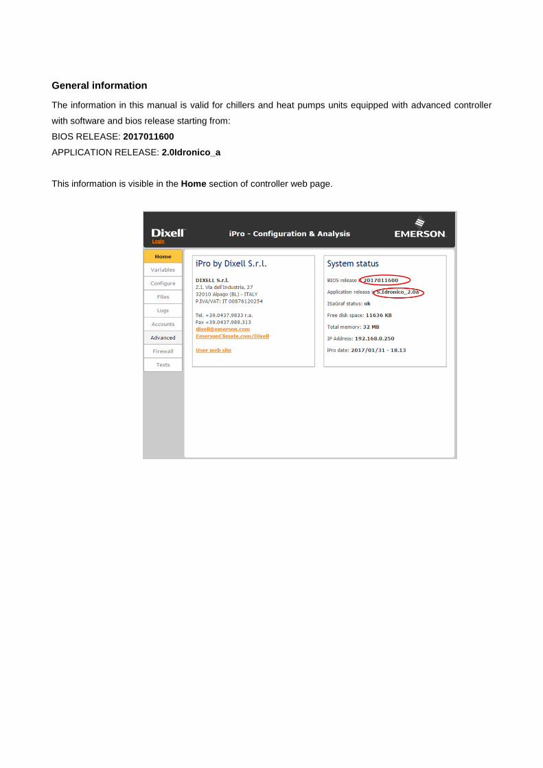
General information The information in this manual is valid for chillers and heat pumps units equipped with advanced controller
with software and bios release starting from:
BIOS RELEASE: 2017011600
APPLICATION RELEASE: 2.0Idronico_a
This information is visible in the Home section of controller web page.

4
1. Advanced Control
The control logic of chillers and heat pumps, allows to satisfy the heating and the cooling plant loads,
according to the selected operating mode, automatically modulating the capacity of the unit.
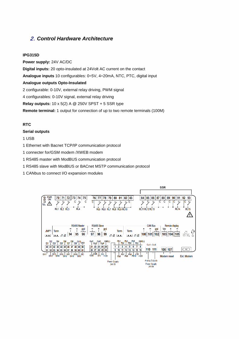
2. Control Hardware Architecture
IPG315D Power supply: 24V AC/DC Digital inputs: 20 opto-insulated at 24Volt AC current on the contact Analogue inputs 10 configurables: 0÷5V, 4÷20mA, NTC, PTC, digital input Analogue outputs Opto-Insulated 2 configurable: 0-10V, external relay driving, PWM signal
4 configurables: 0-10V signal, external relay driving
Relay outputs: 10 x 5(2) A @ 250V SPST + 5 SSR type Remote terminal: 1 output for connection of up to two remote terminals (100M) RTC Serial outputs
1 USB
1 Ethernet with Bacnet TCP/IP communication protocol
1 connecter for/GSM modem /XWEB modem
1 RS485 master with ModBUS communication protocol
1 RS485 slave with ModBUS or BACnet MSTP communication protocol
1 CANbus to connect I/O expansion modules

6
IPG108D / IPG108E: Power supply: 24V AC/DC Digital inputs: 11 opto-insulated at 24Volt AC current on the contact Analogue inputs: 6 configurable: 0÷5V, 4÷20mA, NTC, PTC, digital input Analogue outputs Opto-Insulated: 4 configurable: 0÷10V signal, external relay driving Relay outputs: 8 x 5(2) A @ 250V SPST Remote terminal: 1 output for connection of up to two remote terminals (100M) RTC LED DISPLAY INTEGRATED (IPG108E) Serial outputs 1 USB; BACnet IP using USB/Ethernet adapter
1 RS485 master with ModBUS communication protocol in case of the controller is the MASTER or 1 LAN to
connect I/O expansion module
1 RS485 slave with ModBUS or with BACnet MSTP communication protocol in case of the controller is the
SLAVE

IPX106D: Power supply: 24V AC/DC Digital inputs: 3 opto-insulated Analogue inputs: 7 configurable: 0÷5V, 4÷20mA, NTC, PTC, digital input Analogue outputs Opto-Insulated: 3 configurable: 0÷10V signal, external relay driving Relay outputs: 6 x 5(2) A @ 250V SPST Serial outputs 1 CANbus to connect to IPG315D
1 LAN to connect to IPG108D or IPG108E

8
3. Large Operator Interface
Large chillers and heat pumps are equipped with a visual LCD keyboard, through which it is possible to
monitor and to modify the status and settings of the unit. For smaller units this is available as “Remote Keypad”.
3.1. Main Screen Information reported on the main screen is related to the “Unit status”, to the current date and to the user and
source side water temperatures or ambient temperature:
• Chilled water Return temperature
• Chilled water Leaving temperature
• Hot water Return temperature
• Hot water Leaving temperature
Generic info related to the main components or special functions status is also reported in the main screen
through icons:
• to indicate that at least one of the compressors is working.
• to indicate that the evaporator pump (E) and/or the recovery (R) pump and/or source pump (C)
(in case of water-cooled unit) are working.
• to indicate that the condenser fans are working (in case of air-cooled unit).
• flashing to indicate that at least an alarm is active

• to indicate that the safety capacity reduction mode is in progress
• to indicate that the defrost cycle is in progress, flashing during the count down
• to indicate that the anti-freeze/support heaters are active
• automatic switch-off and/or energy saving is enabled during the current day
• to indicate that the unit is working within the energy saving function or that the dynamic set-
point is active
3.2. Keyboard structure Information on keypad is divided in different menus and sub-sections. The most researched have a direct
link with the main screen by using quick dial keys; the most specific information referred to the status of the
components or to the status of functions, instead, is reported in specific menus into “SERVICE” branch.
Main screen
DisplayUnit statusTime and dateProbes valueEquipments status
DisplayProbes value of all configured circuits
DisplaySet point
DisplayCurrent alarms
DisplayEquipments status in all circuitsCompressorWater pumpFan
Parameters Programming Time/Time periods Compressors Water pump (Supply fan) Alarms Historical alarms
Defrost Heaters/Liquid line solenoid valve
I/O status Thermostatic Valve Heat recovery Auxiliary outputs
Free-cooling Screw compressor Discharge comp. temp. Domestic hot water Auxiliary heating Control panel

10
3.3. Quick link Sections
3.3.1. Probes Section
In the Probes section, accessible pressing the PROBES key in the main screen, all configured sensors are
displayed in different pages. They are reachable using T1 and T8 buttons
From this section, pressing the Cir“x” button, it is possible to enter in the specific circuit sub-section of the
configured circuit n° “x”, where its relevant refrigerant variables are displayed.

3.3.2. Set Point Section
In the Set Point section it is possible to edit the water set-points.
This tab has a direct link with the main screen through the SET button.
In this screen the notifications about the status of the ENERGY SAVING, DYNAMIC SET POINT and
POWER LIMIT functions are also reported.
Cooling and Heating sets are the parameters ST01 and ST04.
The real set represents, instead, the set-point value including the energy saving delta or the dynamic set
delta, and it cannot be modified.
Set points of secondary users, as heat recovery or domestic hot water, will be displayed too, if they are
configured:
HOW TO EDIT SET POINTS
To modify the set point, select the desired one using UP and DOWN buttons and press SET to enable the
editing. The element starts to flash.
Increase or decrease the value using the UP and DOWN keys and press again SET to confirm the new
value.
The cursor will pass automatically to the next element of the list. To modify it, repeat the operation just
described above.
Press the ESC key to go back to the main screen.

12
3.3.3. Alarm Section
When an alarm occurs, the display shows the flashing icon , the alarms key starts to flash alternately
with the icons / and the buzzer starts to operate.
Pressing any key it is possible to turn off the buzzer, to pass to the alarm in progress section it is necessary
to press the “Alarm” button.
Alarms could have three different status:
• Active the alarm is still in progress.
• Resettable in this case, the alarm is not active and can be reset.
• Password in this case, the alarm is not active, but a password is required to reset it.
HOW TO RESET AN ALARM
To reset an alarm, select the desired one using UP and DOWN buttons and press RESET
If the selected one requires to insert a password, a new screen will appear where pressing “+” and “-” keys it
is possible to insert the value. The ENTER button is the confirmation one.
If the inserted password is correct, the message below will be displayed and after few seconds automatically
it will come back to the current alarm screen.
If there are several resettable alarms, instead of selecting them one by one, pressing RST ALL they will be

reset all together.
Press the ESC key to go back to the main screen.
3.3.4. Circuits Info Section
Using the CIRC key in the main screen it is possible to monitor the situation of the unit.
The information refers to:
• Circuits compressors status: the screen shows the compressors present for each circuit, their
activation status and the number of the unloading steps active, in case of compressors have
partialzation valves. If the compressor has no number on the right, it means that it is at full power.
It is shown, also, the notification of the activation of the safety special functions, as oil boost or safety
unloading.
• Condensation-evaporation probes: The screen shows the condensation and evaporation
pressures of every circuit present.
• Status of the evaporator pump (or evaporator pumps if the support one is present).

14
• Status of the recovery pump (or recovery pumps if the support one is present)
• Status of the condencer/source pump on water-cooled units (or condencer/source pumps if the
support one is present)
• Condensation fans on air-cooled units (proportional or steps regulation).
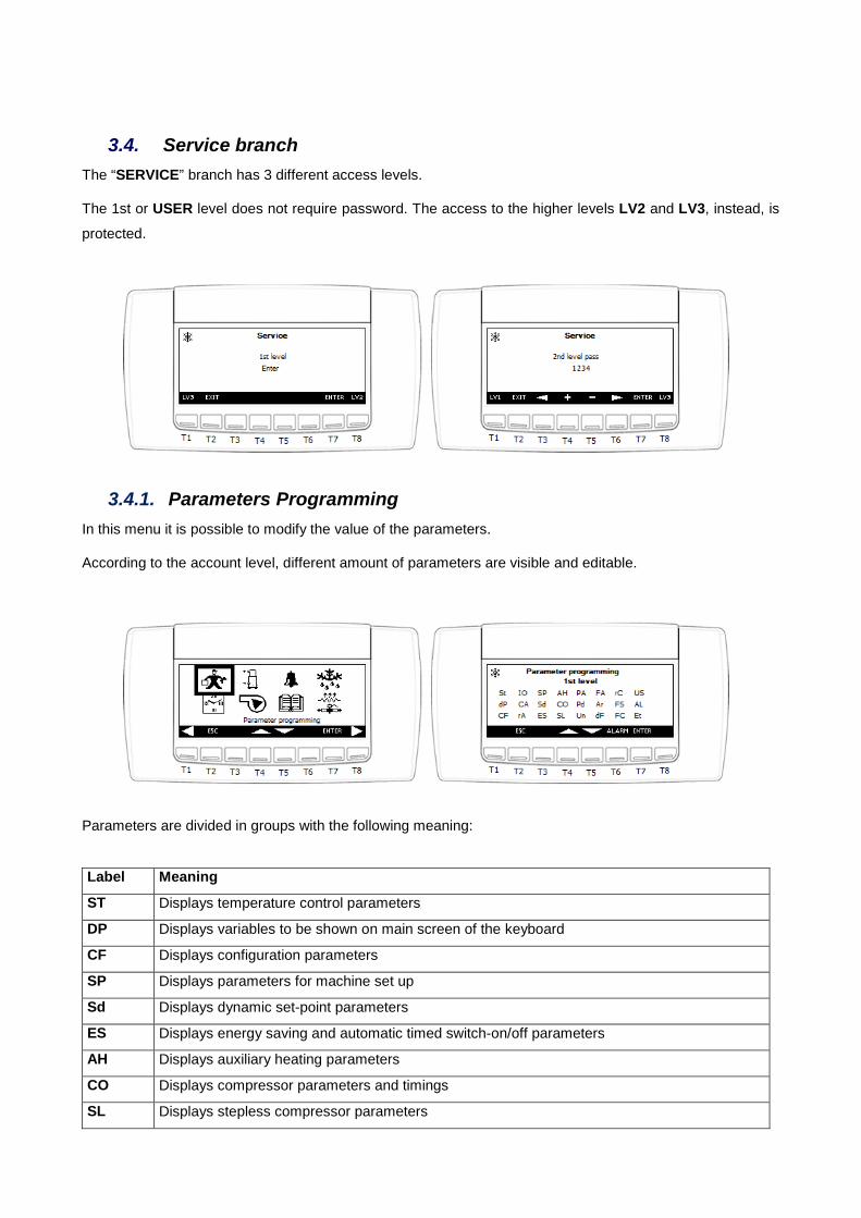
3.4. Service branch The “SERVICE” branch has 3 different access levels.
The 1st or USER level does not require password. The access to the higher levels LV2 and LV3, instead, is
protected.
3.4.1. Parameters Programming In this menu it is possible to modify the value of the parameters.
According to the account level, different amount of parameters are visible and editable.
Parameters are divided in groups with the following meaning:
Label Meaning
ST Displays temperature control parameters
DP Displays variables to be shown on main screen of the keyboard
CF Displays configuration parameters
SP Displays parameters for machine set up
Sd Displays dynamic set-point parameters
ES Displays energy saving and automatic timed switch-on/off parameters
AH Displays auxiliary heating parameters
CO Displays compressor parameters and timings
SL Displays stepless compressor parameters

16
PA Displays evaporator/condenser water pump parameters
Pd Displays pump down function parameters
Un Displays unloading function parameters
FA Displays ventilation parameters
Ar Displays anti-freeze heaters parameters
dF Displays defrost parameters
rC Displays heat recovery parameters
FS Displays production of domestic hot water parameters
FC Displays free-cooling function parameters
US Displays auxiliary output parameters
AL Displays alarm parameters
Et Displays parameters for the management of the electronic expansion valve
IO Displays inputs/outputs configuration parameters
CA Displays analog input calibration parameters
RA Displays analog input range parameters
HOW TO EDIT PARAMETERS
To modify a parameter, select the desired one using UP and DOWN buttons and press SET to enable the
editing. The element starts to flash and its description will be displayed on the bottom of the page.
Increase or decrease the value using the UP and DOWN keys and press again SET to confirm the new
value.
The cursor will pass automatically to the next element of the list. To modify it, repeat the operation just
described above.
Press the ESC key several times to go back to the main screen.
Warning: The access into groups CF, IO, CA and RA, is allowed only if the unit is turned OFF.
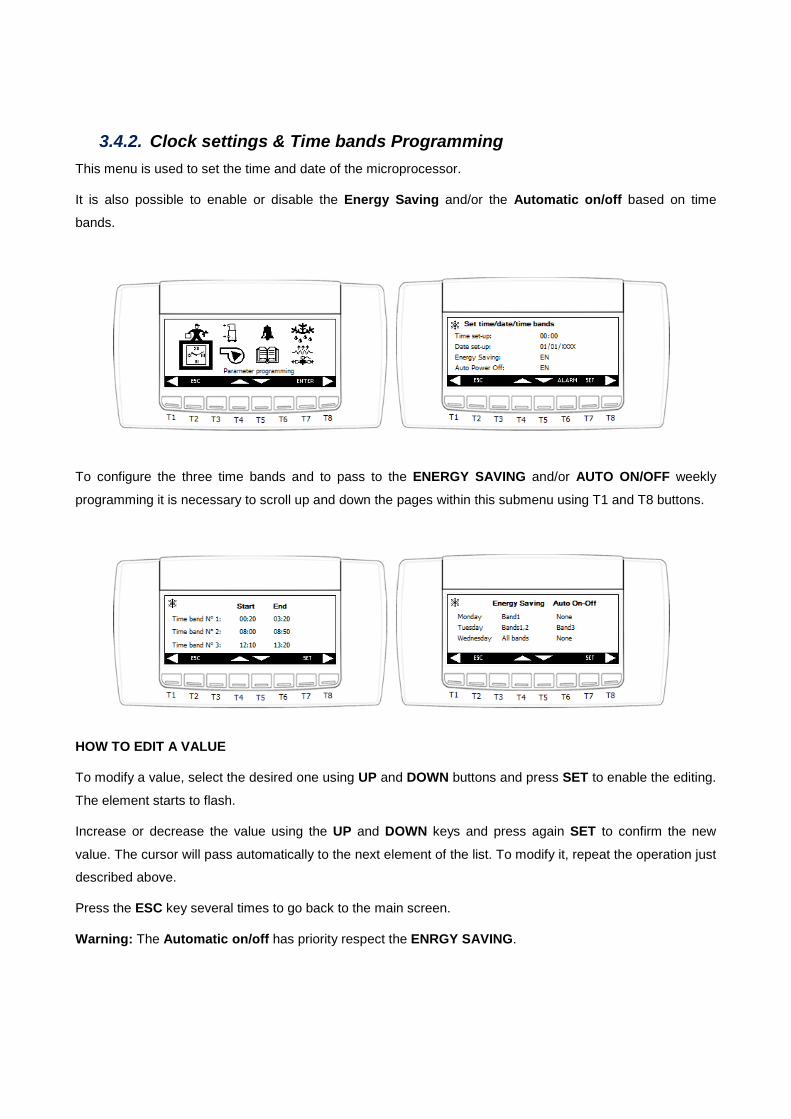
3.4.2. Clock settings & Time bands Programming This menu is used to set the time and date of the microprocessor.
It is also possible to enable or disable the Energy Saving and/or the Automatic on/off based on time
bands.
To configure the three time bands and to pass to the ENERGY SAVING and/or AUTO ON/OFF weekly
programming it is necessary to scroll up and down the pages within this submenu using T1 and T8 buttons.
HOW TO EDIT A VALUE
To modify a value, select the desired one using UP and DOWN buttons and press SET to enable the editing.
The element starts to flash.
Increase or decrease the value using the UP and DOWN keys and press again SET to confirm the new
value. The cursor will pass automatically to the next element of the list. To modify it, repeat the operation just
described above.
Press the ESC key several times to go back to the main screen.
Warning: The Automatic on/off has priority respect the ENRGY SAVING.

18
3.4.3. Compressors Menu
In this submenu the available info for each circuit is:
• Hours worked by each individual compressor
• Number of start-ups for each individual compressor
It is possible to reset the value of the working hours or the number of the start-up. These operation are
protected by password.
It is possible to enable/disable each compressor for maintenance, pressing the key ENB/DIS.
HOW TO RESET A VALUE
To reset a value, select the desired one using UP and DOWN buttons and press RESET HOURS or RESET STARTS.
The screen where to insert the password using “+” and “-” keys will appear. The ENTER button is the one to
confirm the password value.
If the inserted password is correct, the value of the hours or of the start-up will be reset and after few
seconds automatically the previous page will be displayed again.

3.4.4. Water Pumps Menu
In this submenu the available info is:
• Hours worked by each individual water pump
It is possible to reset the value of the working hours. These operation are protected by password.
It is possible to enable/disable each pump for maintenance, pressing the key ENB/DIS.
HOW TO RESET A VALUE
To reset a value, select the desired one using UP and DOWN buttons and press RESET HOURS.
The screen where to insert the password using “+” and “-” keys will appear. The ENTER button is the one to
confirm the password value.
If the inserted password is correct, the value of the hours will be reset and after few seconds automatically
the previous page will be displayed again.
Press the ESC key several times to go back to the main screen.

20
3.4.5. Alarms History Menu
All alarms are memorized and displayed in this screen together to the date and the status of the unit when
the event occurred.
HOW TO RESET ALARMS LOG
To reset the alarms log press RST ALL, holding it down for 3 seconds.
The screen where to insert the password using “+” and “-” keys will appear. The ENTER button is the one to
confirm the password value.
If the inserted password is correct, the alarm list will be reset and after few seconds automatically the
previous page will be displayed again.
Press the ESC key several times to go back to the main screen.

3.4.6. Defrost Menu
In this menu it is possible to check the status of the “Defrost” cycle for each configured refrigerant circuit.
The Defrost status can be:
• Counting EN: In counting down, defrost will start soon
• Cycle EN: Defrost in progress
• Drip time EN: In dripping time
• Waiting: Counter is elapsed but defrost is not required so the circuit is in normal
working
• Condition not present: No necessary condition for defrost
Selecting the circuit, the following screen will be displayed and pressing the button for 5 seconds, while
it is in counting, a manual defrost cycle will be forced.

22
3.4.7. Input / Output Menu
‘This menu allows to check the physical status of all inputs and the logical status of all outputs that have
been defined.
The I/O list of the microprocessor is divided by groups, one per type.
3.4.8. Electronic Expansion valve Menu In this menu it is possible to check the working status of the electronic expansion valves, configured for each
defined circuit. Displayed info for each valve is:
• Suction Temperature
• Suction Pressure
• Opening %
• Superheating Set
• Measured Superheating
The notification about the status of ExV safety special regulation action will be displayed, as LOP, MOP,
LSH, HSH.
Warning: This menu is available only if the ExV driver is integrated with the main microprocessor.

3.4.9. Recovery Menu
In this menu it is possible to check the status of the “Recovery” function, partial or total, and the notification
of configured refrigerant circuits if they are operating in heat recovery mode or not through the “Rec. Valves”
status.
The following information is available in this screen:
• Status of the recovery function:
o Disabled
o Disabled from key
o Enabled
o Active
• Type of priority:
o User side
o Recovery side
Pressing the key for 1 second it is possible to enable/disable the function by keyboard.

24
3.4.10. Free-cooling Menu
In this menu it is possible to check the status of the “Free-Cooling” function, and the value of probes and
settings related to it.
The following information is available in this screen:
• Status of the free-cooling function:
o Disabled
o Disabled from key
o Enabled
o Active
• Type of priority:
o Condensing Pressure
o Free-cooling
o External ventilation
Pressing the key for 1 second it is possible to enable/disable the function by keyboard.

3.4.11. Discharge Compressors Menu
In this menu it is possible to monitor the discharge temperatures of the configured compressors.
In case of the unit is equipped with screw compressors, it is possible to check directly the settings about
the intervention point of the Liquid Injection and High Discharge Temperature Alarm.
Selecting one specific refrigerant circuit and pressing ENTER to access, it is possible to check also the
measured value of the Compressor Discharge Gas sensor and the status of the liquid injection valve and
the status of the valve used to reach the minimum partial load.

26
3.4.12. Domestic hot water Menu
In this menu it is possible to check the status of the “Domestic hot water” function, and the value of probes
and relevant settings related to it.
The following information is available in this screen:
• Status of the domestic hot water function:
o Disabled
o Disabled from key
o Not Requested
o Doing defrost (disabled while defrost cycle is in progress)
o Changing state (in activation)
o Active
Pressing the key for 1 second it is possible to enable/disable the function by keyboard.

3.4.13. Control Panel Menu
Within this menu there are different sub-sections:
• Parameters file management:
In the memory of the microprocessor are saved 2 files parameters map. One called “actual” that
represents the latest saved copy of the parameters map and another one called “default” that
represents the factory settings to erase all preconfigured function.
Within this subsection it is possible to load and to set as parameters map the last saved copy or to
“default” one.
Using the 3rd command “Save as default parameters” it is possible to overwrite the values
contained into the “default” copy with those contained in latest saved copy or “actual”.
Warning: The access in this sub-function is allowed only to the authorized technicians who
have been provided with 3rd level password.
• Contrast & backlight:
Within this subsection it is possible to adjust the label contrast level and the backlight time.
• Log file management:

28
Within this subsection it is possible to send and to save a copy of log files in an external mass
storage, as a USB pen.
• Update Visograph
In this subsection it is possible to force an updating of the keyboard. If the unit is in on this operation
is not allowed.
Warning: Do not remove power supply to the microprocessor and do not disconnect the keypad during the updating.
• Language selection:
In this subsection it is possible to select the language. Available tongues are: Italian, English,
French, Spanish and German.
Warning: Do not remove power supply to the microprocessor and do not disconnect the keypad during the updating.

• System Informations:
In this subsection it is possible to edit the IP address and the MODbus® address. The modification
will be actual at next reboot of the controller.

30
4. Led Operator Interface
Small chillers and heat pumps, equipped with the advanced controller, have the small size one that has a
LED built-in keyboard, through which it is possible to monitor and to modify the status and settings of the
unit.
4.1. Main Screen Info reported on the main screen is related to the “Unit status”.
Pressing key or it is possible to see the value of the configured probes.
First line displays probe value, the second one displays probe name
In case an alarm occur, its code flashes on the second line.
The available probes are:
Display as AI description
EIn Evaporator common input NTC temperature probe
Out1 Evaporator 1 output NTC temperature probe
Out2 Evaporator 2 output NTC temperature probe
EOut Evaporator common outlet NTC temperature probe

CIn Condenser hot water common input NTC temperature probe
CIn1 Circuit 1 condenser hot water input NTC temperature probe
CIn2 Circuit 2 condenser hot water input NTC temperature probe
COu1 Circuit 1 condenser hot water output NTC temperature probe
COu2 Circuit 2 condenser hot water output NTC temperature probe
COut Condenser hot water common output NTC temperature probe
FCIn System water inlet NTC temperature probe (free-cooling)
Et External air temperature
SAn1 Domestic water temperature regulation NTC temperature probe (num. 1)
SAn2 Domestic water temperature safety NTC temperature probe (num. 2)
ROut Heat recovery outlet NTC temperature probe
RIn Heat recovery inlet NTC temperature probe
dSet Dynamic set-point 4÷20 mA probe
CdP1 Circuit 1 condensation probe (pressure 4÷20 mA / ratiometric 0÷ 5Volt)
CdP2 Circuit 2 condensation probe (pressure 4÷20 mA / ratiometric 0÷ 5Volt)
LP1 Circuit 1 evaporation pressure probe (pressure 4÷20 mA / ratiometric 0÷ 5Volt)
LP2 Circuit 2 evaporation pressure probe (pressure 4÷20 mA / ratiometric 0÷ 5Volt)
uSt1 Auxiliary output 1 NTC temperature probe
uSt2 Auxiliary output 2 NTC temperature probe
uSP1 Circuit 1 auxiliary output pressure probe (pressure 4÷20 mA / ratiometric 0÷ 5Volt)
uSP2 Circuit 2 auxiliary output pressure probe (pressure 4÷20 mA / ratiometric 0÷ 5Volt)
Meaning of each LED:
• to indicate that the measurement unit of displayed probe/parameter is in °C.
• to indicate that the measurement unit of displayed probe/parameter is in °F.
• to indicate that RTC is displaying now.
• to indicate that the measurement unit of displayed probe/parameter is in bar.
• to indicate the measurement unit of displayed probe/parameter is in PSI.
• … to indicate if compressors from 1 to 6 are working.

32
• on to indicate that the defrost cycle is in progress, flashing during the countdown.
• to indicate that the condenser fans are working.
• to indicate that the water pump/supply fan is working.
• to indicate that the anti-freeze/auxiliary heaters are active.
• to indicate that the auxiliary outputs are active.
• flashing to indicate that an alarm is active.
• to indicate that the probe display now is belongs to circuit 1.
• to indicate that the probe display now is belongs to circuit 2.
• flashing to indicate that the AEFL or ACFL or AHFL or APFL alarm is active
• to indicate that in heat pump mode.
• to indicate that in chiller mode.
• to indicate that the unit is working within the energy saving period or that the dynamic set-
point is active.
• to indicate that menu screen is displaying.

4.2. Keyboard structure Information on keypad is divided in different menus and sub-sections. The most researched have a direct
link with the main screen by using quick dial keys; the most specific info referred to the status of the
components or to the status of functions, instead, is reported in specific menus into “SERVICE” branch.
Default screen
Display Unit statusAlarm statusProbe value
KEYSwitch unit on/offSwitch chiller/heat pump
KEYEnter in main menu
KEYEnter in clock menu
KEYEnter in set point menu
+ 3 secor + + 3 sec
KEYEnter in parameter menu
1. ALRM (Active alarms)
2. ALOG (Historical alarms)
3. COEn (Compressor en/dis)
4. COSn (Compressor starts num.)
5. Hour (Compressor/pump working hours)
6. PUMP (Water pump en/dis)
7. Cond (Condensation fan)
8. dF (Defrost)
9. InOu (I/O status)
10.Et (Electronic thermostatic valves)
11.FC (Free-cooling)
12.ConF (Configuration file management)
13.USB (USB management)
14.InFO (System information)
Sub menu
KEYS FUNCTIONS
• Press this key to switch on/off the unit to work in heat pump mode.
• Press to enter in main menu screen. Keep press for 3 seconds to adjust clock.
• Press to switch probe being shown
• Press to switch probe being shown
• Press to check set point
• Press this key to switch on/off the unit to work in chiller mode.
• + Press these 2 keys together for 3 seconds to check parameters.

34
4.3. Set Point Section
In the Set Point section it is possible to edit the water set-points.
This tab has a direct link with the main screen through the SET button.
First line displays set point value, the second one displays the type:
• SEtC -> set point in chiller mode (ST01)
• SEtH -> set point in heat pump mode (ST04)
• SEtd -> real set point when dynamic set point is active
• SEtS -> real set point when energy saving is active
• SEtr -> real set point when both dynamic set point and energy saving are active
If the unit is turned off, by keyboard or remotely, scrolling up or down using or it is possible to
see both chiller and heat pump set points. When the unit is turned on, only the one corresponding to the
current operating mode and the real set, if energy saving or dynamic set point are active, are visible.
HOW TO EDIT SET POINTS
To modify the set point, select the desired one using UP and DOWN buttons and press SET for 3 seconds to
enable the editing. The element starts to flash.
Increase or decrease the value using the UP and DOWN keys and press again SET to confirm the new
value.
Press key SET to escape and jump back to the main screen.

4.4. Service branch It is possible to enter in the “SERVICE” branch pressing the MENU key in the default screen.
With UP and DOWN buttons it is possible to scroll on all available sub-menus and pressing SET to enter in
the selected one.
Sub-menu name Visible condition Description
ALRM Always visible Active alarms
ALOG Always visible Historical alarms
COEn Always visible Compressor enable/disable
COSn Always visible Compressor starts number
Hour Always visible Compressor/pump working hours
PUMP No motor-condensing unit Water pump enable/disable
Cond Air-cooled unit Condensation fan
dF Unit in heating mode Defrost
InOu Always visible I/O status
Et Integrated ExV driver is present Electronic expansion valves
ConF Always visible Configuration file management
USB Always visible USB management
InFO Always visible System information
The Menu button has the escape function too.

36
4.4.1. Parameters Programming
Pressing keys + together for 3 seconds in the default screen it is possible to enter into
parameters programming screen.
In this screen, it is possible to select user level.
There are 3 levels, the first one for end user is without password.
Label Meaning
ST Displays temperature control parameters
DP Displays variables to be shown on main screen of the keyboard
CF Displays configuration parameters
SP Displays parameters for machine set up
Sd Displays dynamic set-point parameters
ES Displays energy saving and automatic timed switch-on/off parameters
AH Displays auxiliary heating parameters
CO Displays compressor parameters and timings
SL Displays stepless compressor parameters
PA Displays evaporator/condenser water pump parameters
Pd Displays pump down function parameters
Un Displays unloading function parameters
FA Displays ventilation parameters
Ar Displays anti-freeze heaters parameters
dF Displays defrost parameters
rC Displays heat recovery parameters
FS Displays production of domestic hot water parameters
FC Displays free-cooling function parameters
US Displays auxiliary output parameters
AL Displays alarm parameters
Et Displays parameters for the management of the electronic expansion valve
IO Displays inputs/outputs configuration parameters
CA Displays analog input calibration parameters
RA Displays analog input range parameters
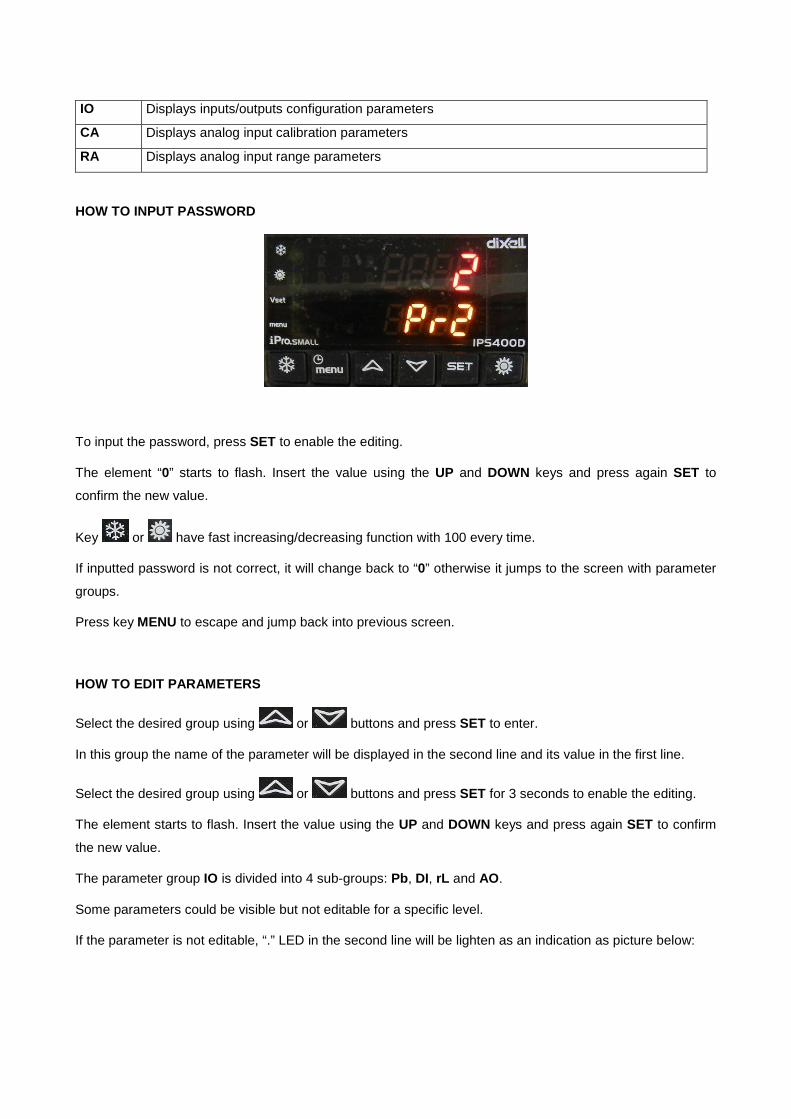
HOW TO INPUT PASSWORD
To input the password, press SET to enable the editing.
The element “0” starts to flash. Insert the value using the UP and DOWN keys and press again SET to
confirm the new value.
Key or have fast increasing/decreasing function with 100 every time.
If inputted password is not correct, it will change back to “0” otherwise it jumps to the screen with parameter
groups.
Press key MENU to escape and jump back into previous screen.
HOW TO EDIT PARAMETERS
Select the desired group using or buttons and press SET to enter.
In this group the name of the parameter will be displayed in the second line and its value in the first line.
Select the desired group using or buttons and press SET for 3 seconds to enable the editing.
The element starts to flash. Insert the value using the UP and DOWN keys and press again SET to confirm
the new value.
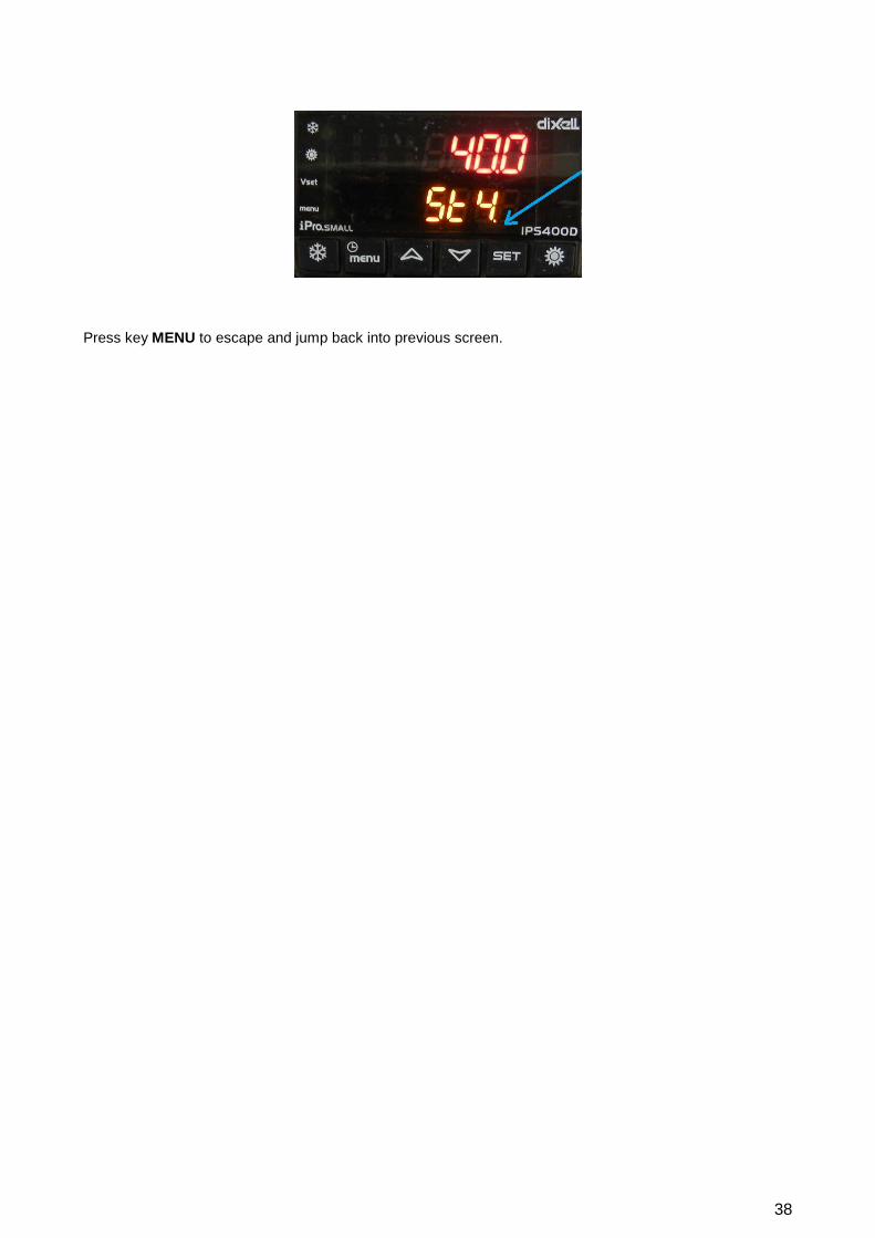
The parameter group IO is divided into 4 sub-groups: Pb, DI, rL and AO.
Some parameters could be visible but not editable for a specific level.
If the parameter is not editable, “.” LED in the second line will be lighten as an indication as picture below:
38
Press key MENU to escape and jump back into previous screen.

4.4.2. Alarm Section
When an alarm occurs, the display shows the flashing led . Entering in the ALRM sub menu of
“SERVICE” branch it is possible to read which specific code is active and reset it, if possible.
In this submenu in the second lines displayed the alarm code, on the first one the status:
• no: still active, not resettable
• rSt: resettable
• PASS: resettable with password
If the alarm is not still active, to reset it is necessary to press key SET. If it requires a password, its input
screen will appear.
HOW TO INPUT PASSWORD
To input the password, press SET for 3 seconds to enable the editing.
The element “0” starts to flash. Insert the value using the UP and DOWN keys and press again SET to
confirm the new value.
Key or have fast increasing/decreasing function with 100 every time.
If inputted password is not correct, it will change back to “0” otherwise it jumps to the other active alarms.
Press key MENU to escape and jump back into previous screen.

40
ALARM CODES TAB
Code Alarm Alarm description AP1 PB1 probe AP2 PB2 probe AP3 PB3 probe AP4 PB4 probe AP5 PB5 probe AP6 PB6 probe AP11 Expansion1 probe1 AP12 Expansion1 probe2 AP13 Expansion1 probe3 AP14 Expansion1 probe4 AP15 Expansion1 probe5 AP16 Expansion1 probe6 AP17 Expansion1 probe7 AP39 XEV20D 1 probe1 AP40 XEV20D 1 probe2 AP41 XEV20D 1 probe3 AP42 XEV20D 1 probe4 AP43 XEV20D 2 probe1 AP44 XEV20D 2 probe2 AP45 XEV20D 2 probe3 AP46 XEV20D 2 probe4 AEFL Evaporator flow switch alarm ACFL Condenser flow switch alarm AtSF Supply fan circuit breaker alarm AEUn Evaporator unloading signalling AtE1 Evaporator n° 1 water pump overload AtE2 Support evaporator n° 2 water pump overload AtC1 Condenser n° 1 water pump overload AtC2 Support condenser n° 2 water pump overload AEP1 Evaporator n° 1 water pump maintenance AEP2 Support evaporator n° 2 water pump maintenance ACP1 Condenser n° 1 water pump maintenance ACP2 Support condenser n° 2 water pump maintenance AHFL Domestic hot water pump flow switch alarm ARFL Recovery flow switch alarm AEht Evaporator water inlet high temperature alarm AET1 XEV20D 1 not connected alarm AET2 XEV20D 2 not connected alarm AEM1 IPROEX60D 1 not connected alarm AFFC Anti-freeze alarm in free-cooling AtR1 Recovery n° 1 water pump overload AtR2 Support recovery n° 2 water pump overload AfnA Function not available alarm ASPh Phases sequence alarm ALc1 Generic alarm 1 ARP1 Recovery n° 1 water pump maintenance ARP2 Recovery n° 2 water pump maintenance ACFx Configuration alarm n° “x” AC1n Configuration alarm n° 1”x”
Code Alarm Alarm description b(n)HP Circuit high pressure switch (n) b(n)LP Circuit low pressure switch (n)

b(n)AC Anti-freeze in cooling circuit (n) b(n)AH Anti-freeze in heating circuit (n) b(n)A Source Anti-freeze alarm in circuit (n) b(n)hP Condensing high pressure transducer circuit (n) b(n)lP Circuit (n) low evaporating pressure b(n)tF Circuit fan overload alarm (n) b(n)dF Circuit defrost alarm signal(n) b(n)Cu Unloading signal due to circuit (n) high condensing temp. / press. b(n)Eu Unloading signal due to circuit (n) evaporating low temp. b(n)rC Circuit (n) heat recovery disabling signal b(n)PH Circuit pump down stopping alarm (n) b(n)PL Circuit pump down start-up alarm (n)
Code Alarm Alarm description C(n)HP Compressor (n) high pressure switch C(n)oP Compressor (n) oil pressure switch/oil float C(n)tr Compressor overload(n) C(n)dt Compressor high discharge temperature C(n)Mn Compressor maintenance (n)
4.4.3. Alarm History Section
All alarms are memorized and displayed in the “ALOG” sub-menu together to the date and the status of the
unit when the event occurred.
In the first screen the alarm code is displayed together to its event number in an hour. Pressing SET it is
possible to see more detailed info including the status of the unit and the date when the alarm occurred.
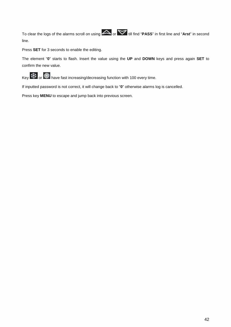
HOW TO DELETE ALARMS LOG
42
To clear the logs of the alarms scroll on using or till find “PASS” in first line and “Arst” in second
line.
Press SET for 3 seconds to enable the editing.
The element “0” starts to flash. Insert the value using the UP and DOWN keys and press again SET to
confirm the new value.
Key or have fast increasing/decreasing function with 100 every time.
If inputted password is not correct, it will change back to “0” otherwise alarms log is cancelled.
Press key MENU to escape and jump back into previous screen.
4.4.4. Compressors Menu
In “COEn” submenu it is possible to enable and disable the compressors for maintenance. Info about
working hour and the number of the start-up is reported into two different submenus.
On the second line is reported the compressor index and on first is reported its current status
Press key or to scan all configured compressors and press SET button for 3 seconds to modify
the en/dis status of the selected one.
Press key MENU to escape and jump back into previous screen.
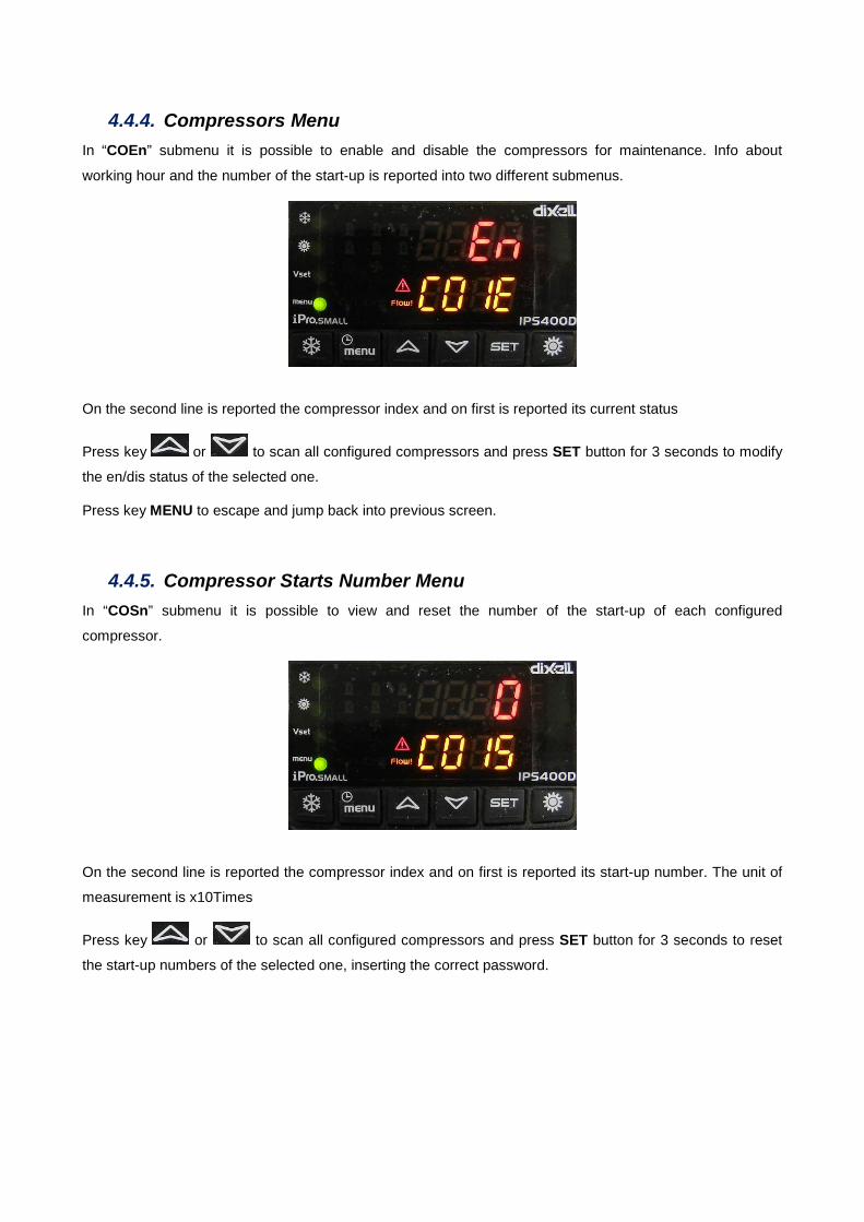
4.4.5. Compressor Starts Number Menu
In “COSn” submenu it is possible to view and reset the number of the start-up of each configured
compressor.
On the second line is reported the compressor index and on first is reported its start-up number. The unit of
measurement is x10Times
Press key or to scan all configured compressors and press SET button for 3 seconds to reset
the start-up numbers of the selected one, inserting the correct password.

44
4.4.6. Water Pump Menu
In “PUMP” submenu it is possible to enable and disable the water pumps for maintenance. Info about
working hour is reported into a different submenu. It is not visible on motor-condensing units.
On the second line is reported the pump index and on first is reported its current status
Press key or to scan all configured water pumps and press SET button for 3 seconds to modify
the en/dis status of the selected one.
Press key MENU to escape and jump back into previous screen.
4.4.7. Compressors & Pumps Working Hour Menu
In “HOUR” submenu it is possible to view and reset the working hours of each compressor and water pump.
On the second line is reported the compressor or pump index and on first is reported the value of its working
hour.
Press key or to scan all configured water pumps and press SET button for 3 seconds to reset it,
inserting the correct password.

4.4.8. Condensing Fan Menu
In “COND” submenu it is possible to see the working status of the condensing / evaporating fans.
It is visible only on air-cooled version units.
On the second line is reported the fan circuit index and on first is reported its current output value:
• 0-100 : in case of continuous fan control
• 0-4: in case of step control
Press key MENU to escape and jump back into previous screen.
4.4.9. Defrost Menu
In “dF” submenu it is possible to see the working status of the defrost cycle.
It is visible only on heat pumps during their operation in heating mode.
On the first line is reported the circuit index and on second is displayed the countdown before that a defrost
cycle starts.
Pressing key SET for 3 seconds it is possible to force a defrost cycle manually.
Press key MENU to escape and jump back into previous screen.

46
4.4.10. Input / Output Menu
In “InOu” submenu it is possible to see the status of the input and output of the controller.
The I/O list is divided in 4 groups:
• Pb: analog input
• di: digital input
• rL: digital output
• out: analog output
Press key or to scan all type and press SET button to enter.
Using the UP and DOWN it is possible to scroll on the list.
PROBES (Pb) DIGITAL INPUT (di)
RELAY (rL) ANALOG OUTPUT (out)
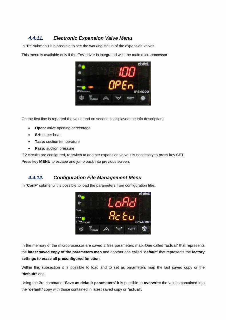
4.4.11. Electronic Expansion Valve Menu
In “Et” submenu it is possible to see the working status of the expansion valves.
This menu is available only if the ExV driver is integrated with the main microprocessor
On the first line is reported the value and on second is displayed the info description:
• Open: valve opening percentage
• SH: super heat
• Tasp: suction temperature
• Pasp: suction pressure
If 2 circuits are configured, to switch to another expansion valve it is necessary to press key SET.
Press key MENU to escape and jump back into previous screen.
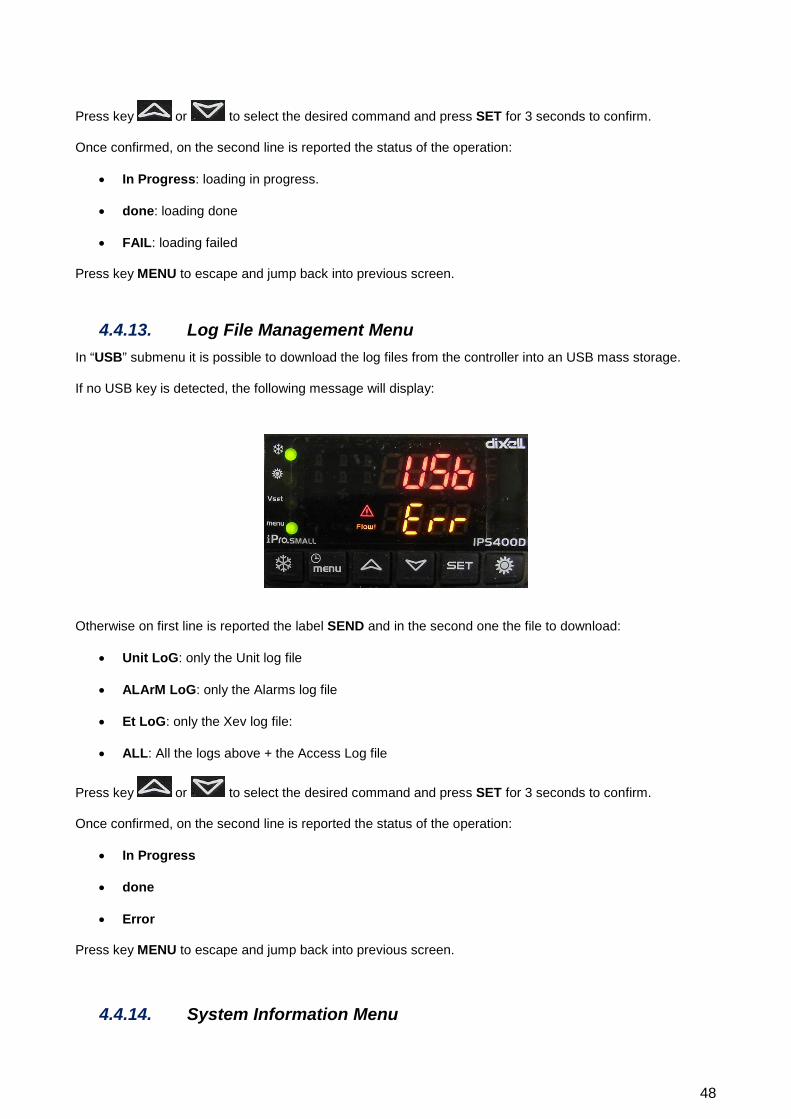
4.4.12. Configuration File Management Menu
In “ConF” submenu it is possible to load the parameters from configuration files.
In the memory of the microprocessor are saved 2 files parameters map. One called “actual” that represents
the latest saved copy of the parameters map and another one called “default” that represents the factory settings to erase all preconfigured function.
Within this subsection it is possible to load and to set as parameters map the last saved copy or the
“default” one.
Using the 3rd command “Save as default parameters” it is possible to overwrite the values contained into
the “default” copy with those contained in latest saved copy or “actual”.
48
Press key or to select the desired command and press SET for 3 seconds to confirm.
Once confirmed, on the second line is reported the status of the operation:
• In Progress: loading in progress.
• done: loading done
• FAIL: loading failed
Press key MENU to escape and jump back into previous screen.
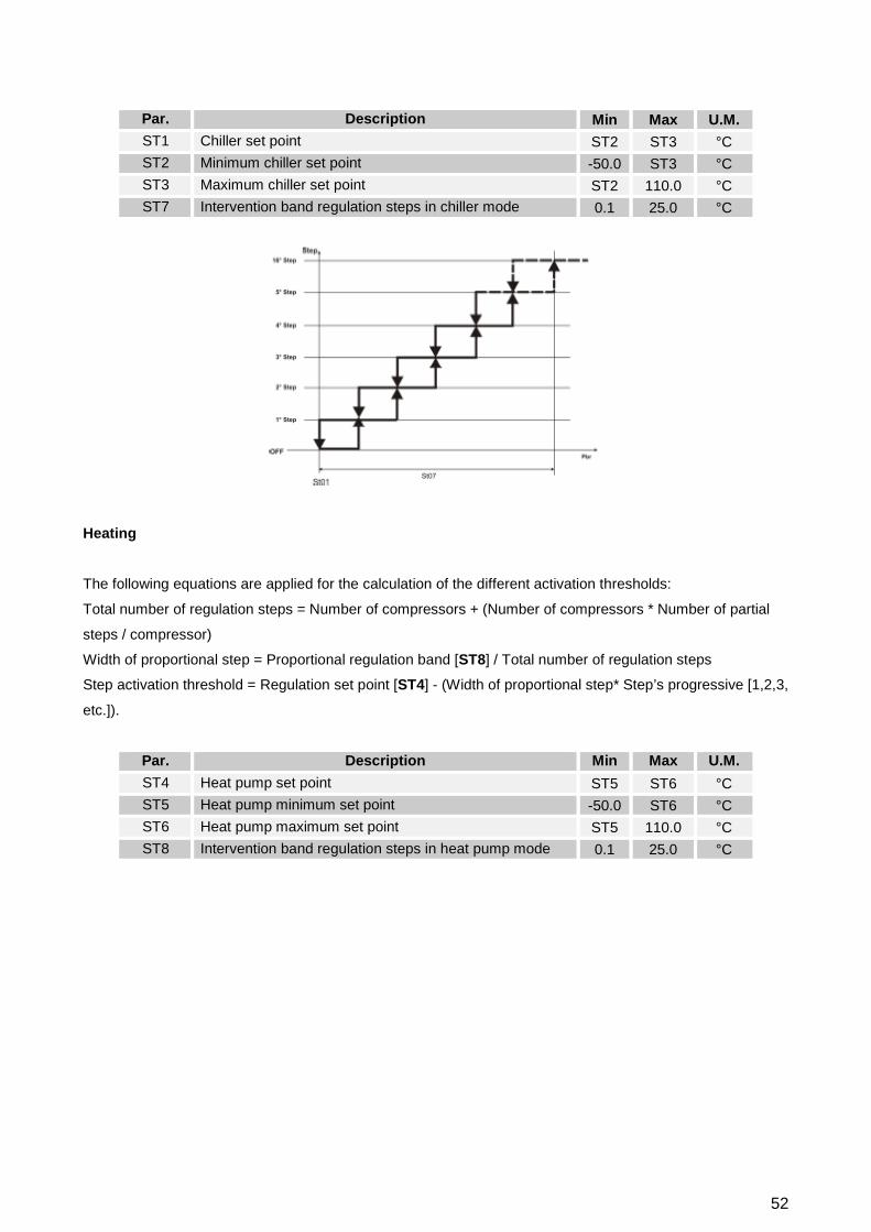
4.4.13. Log File Management Menu
In “USB” submenu it is possible to download the log files from the controller into an USB mass storage.
If no USB key is detected, the following message will display:
Otherwise on first line is reported the label SEND and in the second one the file to download:
• Unit LoG: only the Unit log file
• ALArM LoG: only the Alarms log file
• Et LoG: only the Xev log file:
• ALL: All the logs above + the Access Log file
Press key or to select the desired command and press SET for 3 seconds to confirm.
Once confirmed, on the second line is reported the status of the operation:
• In Progress
• done
• Error
Press key MENU to escape and jump back into previous screen.
4.4.14. System Information Menu

In “InFO” submenu it is possible to see some system information.
The available info is:
• APP: software application name
• Adr: Modbus address
• IP: IP address
Press key or to scroll on the information.
Press key MENU to escape and jump back into previous screen.

50
5. Unit Activation
At the unit startup, the main screen of units will show:
It is possible to activate the unit using the keyboard:
• In “Chilled water production mode” pressing the sun button .
• In “Hot water production mode” pressing the snow button .

6. Temperature Control
The units provides different regulation modes.
By modifying the parameters ST9 and ST10 the probes can be defined on which the temperature control of
the unit, either in cooling mode or in heating mode, is based on.
By modifying the parameters ST11 the control mode between the followings can be selected:
• Proportional step regulation: suggested with temperature control based on the return to the unit
• Neutral zone: strongly recommended with temperature control based on the delivery.
Par. Description Min Max U.M. ST9 Chilled water temperature control probe 0 7 ST10 Hot water temperature control probe 0 3 ST11 Defines the type of temperature control 0 4
In both case before to activate or deactivate a compressor / partial step, the microprocessor will respect the
parameters in the tab below in order to avoid compressors short cycling.
Par. Description Min Max U.M. CO1 Compressor minimum ON time 1 250 10sec CO2 Compressor minimum OFF time 0 250 10sec CO3 Minimum time between one activation and another on the same compressor 0 250 10sec CO4 Activation delay between 2 compressors/steps 1 250 sec CO5 Deactivation delay between 2 compressors/steps 1 250 sec
6.1. Proportional Step Regulation
The regulation band will be divided in a number of intervals (steps) depending on the total number of the
compressors in the unit and on their possible partial steps. This implies that for each step an activation
threshold and a deactivation one will be defined.
When the value measured by the selected temperature control probe cross these threshold, the activation /
deactivation request of one or more compressors/partial steps occurs.
Cooling
The following equations are applied for the calculation of the different activation thresholds:
Total number of regulation steps = Number of compressors + (Number of compressors * Number of partial
steps / compressor)
Width of proportional step = Proportional regulation band [ST7] / Total number of regulation steps
Step activation threshold = regulation set point [ST1] + (Width of proportional step* Step’s progressive [1,2,3,
etc.]).
52
Par. Description Min Max U.M. ST1 Chiller set point ST2 ST3 °C ST2 Minimum chiller set point -50.0 ST3 °C ST3 Maximum chiller set point ST2 110.0 °C ST7 Intervention band regulation steps in chiller mode 0.1 25.0 °C
Heating
The following equations are applied for the calculation of the different activation thresholds:
Total number of regulation steps = Number of compressors + (Number of compressors * Number of partial
steps / compressor)
Width of proportional step = Proportional regulation band [ST8] / Total number of regulation steps
Step activation threshold = Regulation set point [ST4] - (Width of proportional step* Step’s progressive [1,2,3,
etc.]).
Par. Description Min Max U.M. ST4 Heat pump set point ST5 ST6 °C ST5 Heat pump minimum set point -50.0 ST6 °C ST6 Heat pump maximum set point ST5 110.0 °C ST8 Intervention band regulation steps in heat pump mode 0.1 25.0 °C
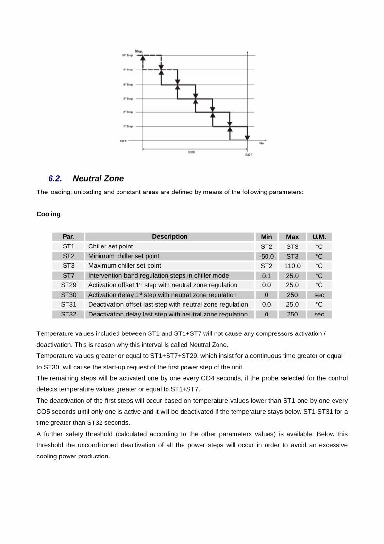
6.2. Neutral Zone
The loading, unloading and constant areas are defined by means of the following parameters:
Cooling
Par. Description Min Max U.M. ST1 Chiller set point ST2 ST3 °C ST2 Minimum chiller set point -50.0 ST3 °C ST3 Maximum chiller set point ST2 110.0 °C ST7 Intervention band regulation steps in chiller mode 0.1 25.0 °C ST29 Activation offset 1st step with neutral zone regulation 0.0 25.0 °C ST30 Activation delay 1st step with neutral zone regulation 0 250 sec ST31 Deactivation offset last step with neutral zone regulation 0.0 25.0 °C ST32 Deactivation delay last step with neutral zone regulation 0 250 sec
Temperature values included between ST1 and ST1+ST7 will not cause any compressors activation /
deactivation. This is reason why this interval is called Neutral Zone.
Temperature values greater or equal to ST1+ST7+ST29, which insist for a continuous time greater or equal
to ST30, will cause the start-up request of the first power step of the unit.
The remaining steps will be activated one by one every CO4 seconds, if the probe selected for the control
detects temperature values greater or equal to ST1+ST7.
The deactivation of the first steps will occur based on temperature values lower than ST1 one by one every
CO5 seconds until only one is active and it will be deactivated if the temperature stays below ST1-ST31 for a
time greater than ST32 seconds.
A further safety threshold (calculated according to the other parameters values) is available. Below this
threshold the unconditioned deactivation of all the power steps will occur in order to avoid an excessive
cooling power production.

54
Heating
Par. Description Min Max U.M. ST4 Heat pump set point ST5 ST6 °C ST5 Heat pump minimum set point -50.0 ST6 °C ST6 Heat pump maximum set point ST5 110.0 °C ST8 Intervention band regulation steps in heat pump mode 0.1 25.0 °C ST29 Activation offset 1st step with neutral zone regulation 0.0 25.0 °C ST30 Activation delay 1st step with neutral zone regulation 0 250 sec ST31 Deactivation offset last step with neutral zone regulation 0.0 25.0 °C ST32 Deactivation delay last step with neutral zone regulation 0 250 sec
Temperature values included between ST4 and ST4-ST8 will not cause any compressors activation /
deactivation. This is reason why this interval is called Neutral Zone.
Temperature values lower than or equal to ST4-ST8-ST29, which insist for a continuous time greater or
equal to ST30, will cause the switch-on of the first power step of the system.
The remaining steps will be activated one by one every CO4 seconds, if the probe selected for the control
detects temperature values lower than or equal to ST4-ST8.
The deactivation of the first steps will occur based on temperature values greater than ST4 one by one every
CO5 seconds until only one is active and it will be deactivated if the temperature stays over ST4+ST31 for a
time greater than ST32 seconds.
A further safety threshold (calculated according the other parameters values) is available. Over that
threshold the unconditioned deactivation of all the power steps will occur in order to avoid an excessive
heating power production.
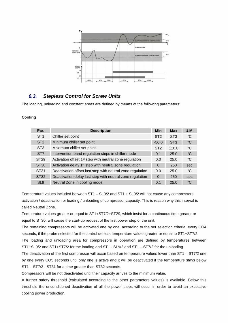
6.3. Stepless Control for Screw Units
The loading, unloading and constant areas are defined by means of the following parameters:
Cooling
Par. Description Min Max U.M. ST1 Chiller set point ST2 ST3 °C ST2 Minimum chiller set point -50.0 ST3 °C ST3 Maximum chiller set point ST2 110.0 °C ST7 Intervention band regulation steps in chiller mode 0.1 25.0 °C ST29 Activation offset 1st step with neutral zone regulation 0.0 25.0 °C ST30 Activation delay 1st step with neutral zone regulation 0 250 sec ST31 Deactivation offset last step with neutral zone regulation 0.0 25.0 °C ST32 Deactivation delay last step with neutral zone regulation 0 250 sec SL9 Neutral Zone in cooling mode 0.1 25.0 °C
Temperature values included between ST1 – SL9/2 and ST1 + SL9/2 will not cause any compressors
activation / deactivation or loading / unloading of compressor capacity. This is reason why this interval is
called Neutral Zone.
Temperature values greater or equal to ST1+ST7/2+ST29, which insist for a continuous time greater or
equal to ST30, will cause the start-up request of the first power step of the unit.
The remaining compressors will be activated one by one, according to the set selection criteria, every CO4
seconds, if the probe selected for the control detects temperature values greater or equal to ST1+ST7/2.
The loading and unloading area for compressors in operation are defined by temperatures between
ST1+SL9/2 and ST1+ST7/2 for the loading and ST1 - SL9/2 and ST1 – ST7/2 for the unloading.
The deactivation of the first compressor will occur based on temperature values lower than ST1 – ST7/2 one
by one every CO5 seconds until only one is active and it will be deactivated if the temperature stays below
ST1 – ST7/2 - ST31 for a time greater than ST32 seconds.
Compressors will be not deactivated until their capacity arrives to the minimum value.
A further safety threshold (calculated according to the other parameters values) is available. Below this
threshold the unconditioned deactivation of all the power steps will occur in order to avoid an excessive
cooling power production.
56
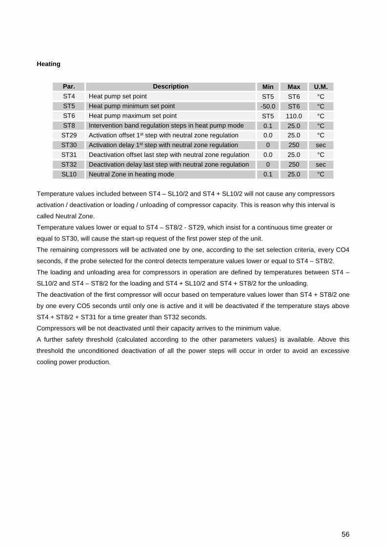
Heating
Par. Description Min Max U.M. ST4 Heat pump set point ST5 ST6 °C ST5 Heat pump minimum set point -50.0 ST6 °C ST6 Heat pump maximum set point ST5 110.0 °C ST8 Intervention band regulation steps in heat pump mode 0.1 25.0 °C ST29 Activation offset 1st step with neutral zone regulation 0.0 25.0 °C ST30 Activation delay 1st step with neutral zone regulation 0 250 sec ST31 Deactivation offset last step with neutral zone regulation 0.0 25.0 °C ST32 Deactivation delay last step with neutral zone regulation 0 250 sec SL10 Neutral Zone in heating mode 0.1 25.0 °C
Temperature values included between ST4 – SL10/2 and ST4 + SL10/2 will not cause any compressors
activation / deactivation or loading / unloading of compressor capacity. This is reason why this interval is
called Neutral Zone.
Temperature values lower or equal to ST4 – ST8/2 - ST29, which insist for a continuous time greater or
equal to ST30, will cause the start-up request of the first power step of the unit.
The remaining compressors will be activated one by one, according to the set selection criteria, every CO4
seconds, if the probe selected for the control detects temperature values lower or equal to ST4 – ST8/2.
The loading and unloading area for compressors in operation are defined by temperatures between ST4 –
SL10/2 and ST4 – ST8/2 for the loading and ST4 + SL10/2 and ST4 + ST8/2 for the unloading.
The deactivation of the first compressor will occur based on temperature values lower than ST4 + ST8/2 one
by one every CO5 seconds until only one is active and it will be deactivated if the temperature stays above
ST4 + ST8/2 + ST31 for a time greater than ST32 seconds.
Compressors will be not deactivated until their capacity arrives to the minimum value.
A further safety threshold (calculated according to the other parameters values) is available. Above this
threshold the unconditioned deactivation of all the power steps will occur in order to avoid an excessive
cooling power production.

6.4. Partial Heat Recovery The temperature control of the partial recovery user is present only if it was requested it is a single
proportional step type based on return temperature.
Par. Description Min Max U.M. RC13 Heat Recovery water set point RC11 RC12 °C RC14 Heat Recovery water regulation differential 0.1 25.0 °C RC11 Minimum heat recovery water set point value -50.0 RC12 °C RC12 Maximum heat recovery water set point value RC11 110.0 °C
The desuperheater is active if the request is ON while there is at least one compressor in operation and
none refrigerant circuit is performing a defrost cycle. It is possible to enable/disable this function by keyboard as reported on chapter 3.4.9.
6.5. Total Heat Recovery The temperature control of the total recovery user, if present, is a proportional step type based on return
temperature.
The number of the available steps is equal to the number of the refrigerant circuit presents.

58
Par. Description Min Max U.M. RC13 Heat Recovery water set point RC11 RC12 °C RC14 Heat Recovery water regulation differential 0.1 25.0 °C RC11 Minimum heat recovery water set point value -50.0 RC12 °C RC12 Maximum heat recovery water set point value RC11 110.0 °C
The heat recovery, in this case, is active if the request is ON while there is at least one requested
compressor to satisfy the main user.
This function “enables” the amount of circuits to operate in heat recovery, according to the request, but it is
the chilled water production to determine the number of steps that have to operate. It is possible to enable/disable this function by keyboard as reported on chapter 3.4.9.
6.6. Domestic hot water control by 3way valve The temperature control of the domestic hot water user, if present, is a proportional step type based on
measured temperature by the sensor to install in sanitary water tank.
Par. Description Min Max U.M. FS2 Space heating Priority Vs Dom. hot water Priority 0 1 FS3 Domestic water set point FS5 FS6 °C FS4 Domestic water regulation differential 0.1 25.0 °C FS5 Minimum domestic water set point value -50.0 FS6 °C FS6 Maximum domestic water set point value FS5 110.0 °C
The number of the available steps depends on the total number of the compressors in the unit and on their
possible partial steps.
Factory Priority is set on domestic hot water production.
The domestic hot water is active if the request is ON and none refrigerant circuit is performing a defrost
cycle. It is possible to enable/disable this function by keyboard as reported on chapter 3.4.12.

7. Water Pumps Management
The management of pump groups is related to the value of the parameter Pump Operation Mode:
Par. Description Min Max Note PA1 Evaporator pump operation mode 0 2 Chilled water side PA17 Source pump operation mode 0 2 Source side on water cooled units PA31 Recovery pump operation mode 0 2 Hot water side
• 0: Not Present
• 1: Continuously – The pump is always active when the unit is active not depending on the operation
of the compressors.
• 2: On demand – The pump is active just when a capacity step is required.
The controller ensures that times and delays between switch-on/switch-off of the compressors and pumps
are respected.
In case of detection of freeze alarm condition, the microprocessor will force to switch on the pumps.
Evaporator Pump
Par. Description Min Max U.M. PA2 First Compressor ON delay from pump starting-up 0 250 10sec PA3 Evaporator water pump OFF delay from last compressor stops 0 250 10sec PA4 Deactivation Pump Delay from unit turning Off 0 250 10sec
Condenser Pump / Source water side on water cooled units
Par. Description Min Max U.M. PA18 First Compressor ON delay from starting-up 0 250 10sec PA19 Condenser pump OFF delay from last compressor stops 0 250 10sec PA20 Deactivation Pump Delay from unit turning Off 0 250 10sec
Heat Recovery Pump
Par. Description Min Max U.M. PA32 First Compressor ON delay from pump starting-up 0 250 10sec PA33 Recovery water pump OFF delay from last compressor stops 0 250 10sec PA34 Deactivation Pump Delay from unit turning Off 0 250 10sec
60
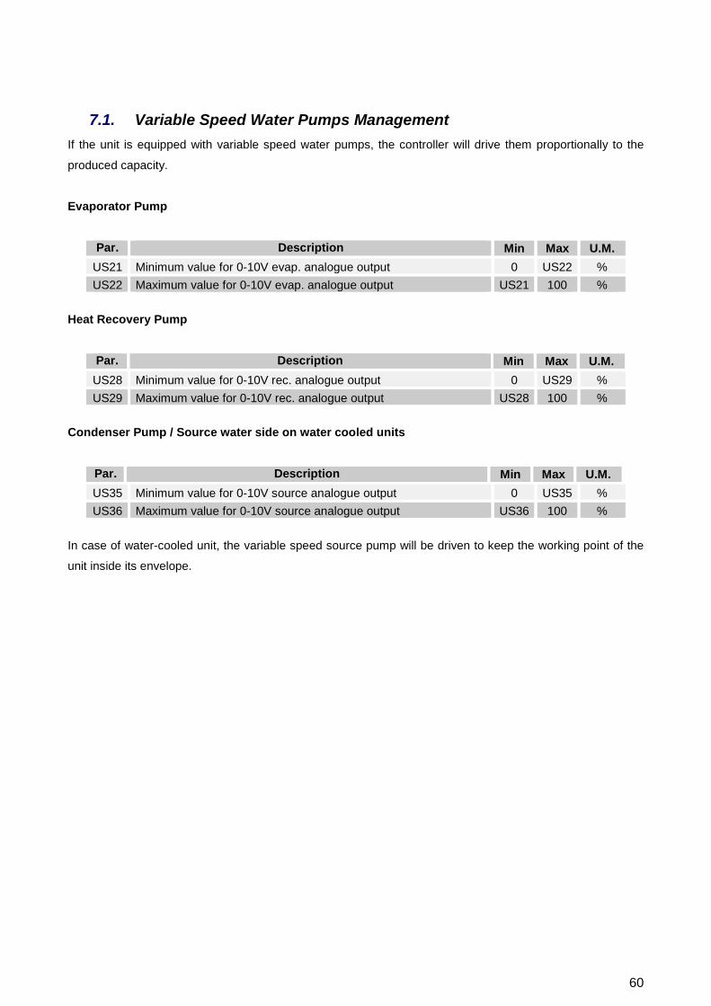
7.1. Variable Speed Water Pumps Management If the unit is equipped with variable speed water pumps, the controller will drive them proportionally to the
produced capacity.
Evaporator Pump
Par. Description Min Max U.M. US21 Minimum value for 0-10V evap. analogue output 0 US22 % US22 Maximum value for 0-10V evap. analogue output US21 100 %
Heat Recovery Pump
Par. Description Min Max U.M. US28 Minimum value for 0-10V rec. analogue output 0 US29 % US29 Maximum value for 0-10V rec. analogue output US28 100 %
Condenser Pump / Source water side on water cooled units
Par. Description Min Max U.M. US35 Minimum value for 0-10V source analogue output 0 US35 % US36 Maximum value for 0-10V source analogue output US36 100 %
In case of water-cooled unit, the variable speed source pump will be driven to keep the working point of the
unit inside its envelope.
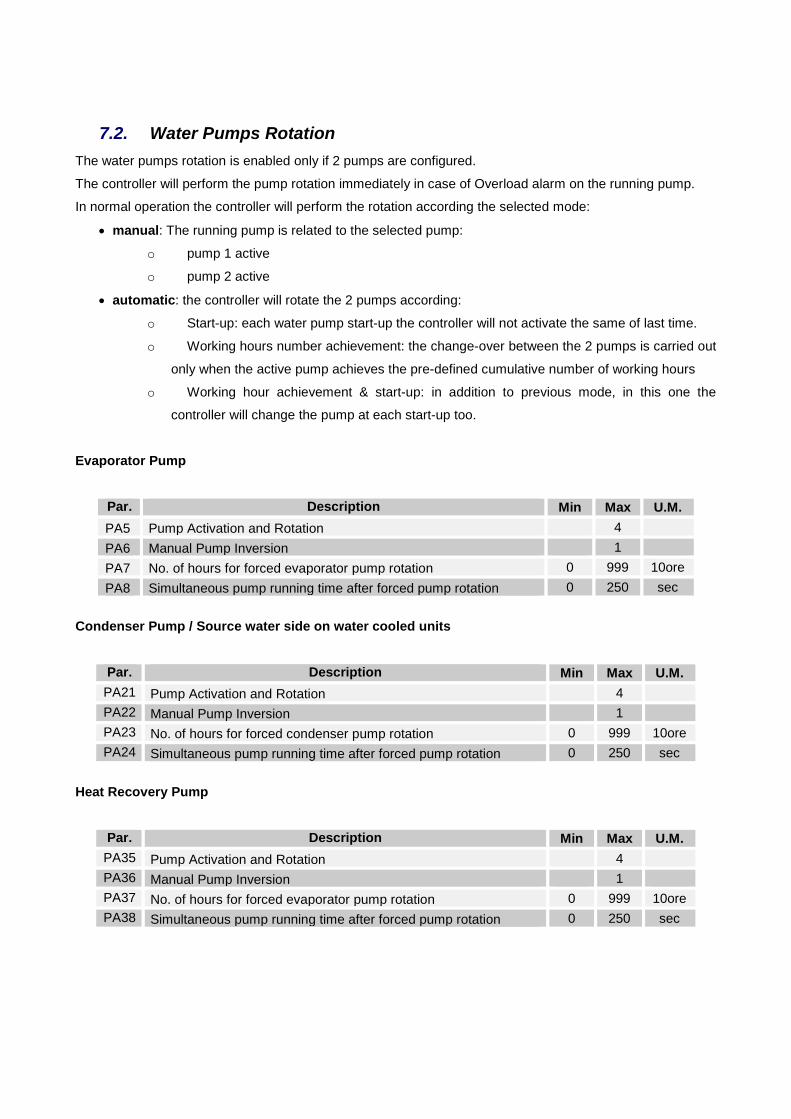
7.2. Water Pumps Rotation The water pumps rotation is enabled only if 2 pumps are configured.
The controller will perform the pump rotation immediately in case of Overload alarm on the running pump.
In normal operation the controller will perform the rotation according the selected mode:
• manual: The running pump is related to the selected pump:
o pump 1 active
o pump 2 active
• automatic: the controller will rotate the 2 pumps according:
o Start-up: each water pump start-up the controller will not activate the same of last time.
o Working hours number achievement: the change-over between the 2 pumps is carried out
only when the active pump achieves the pre-defined cumulative number of working hours
o Working hour achievement & start-up: in addition to previous mode, in this one the
controller will change the pump at each start-up too.
Evaporator Pump
Par. Description Min Max U.M. PA5 Pump Activation and Rotation 4 PA6 Manual Pump Inversion 1 PA7 No. of hours for forced evaporator pump rotation 0 999 10ore PA8 Simultaneous pump running time after forced pump rotation 0 250 sec
Condenser Pump / Source water side on water cooled units
Par. Description Min Max U.M. PA21 Pump Activation and Rotation 4 PA22 Manual Pump Inversion 1 PA23 No. of hours for forced condenser pump rotation 0 999 10ore PA24 Simultaneous pump running time after forced pump rotation 0 250 sec
Heat Recovery Pump
Par. Description Min Max U.M. PA35 Pump Activation and Rotation 4 PA36 Manual Pump Inversion 1 PA37 No. of hours for forced evaporator pump rotation 0 999 10ore PA38 Simultaneous pump running time after forced pump rotation 0 250 sec

62
8. Low Water Flow Alarm Management
A differential pressure switch is installed on the exchangers of the unit.
It is mandatory to install an additional paddle flow switch (one per user) on pipes close to the unit and wires
its digital contact in series to the one on board.
In the control loop there is a delay to bypass the alarm at pump start-up in order to wait that valves on
hydraulic side (if present) are completely open before to launch an alarm.
During the compressor operation there is another shorter bypass delay to avoid false alarms due to a
transient situation.
The low water flow alarms are serious alarms. They block completely the unit and their automatic reset is
based on the time the digital input remains open after the alarm detection.
The low water flow control operates during the working period of pump.
User’s water sides
Par. Description Min Max U.M. PA2 First Compressor ON delay from evap. pump starting-up 0 250 10sec PA32 First Compressor ON delay from rec. pump starting-up 0 250 10sec AL16 Evaporator flow switch alarm by-pass by activating the evaporator
pump/supply fan 0 250 sec
AL17 Maximum time in evaporator flow switch alarm before switching to manual mode and blocking the evaporator water pump, if moving 0 250 sec
AL18 Evaporator flow switch / thermal overload supply fan input active duration 0 250 sec
Warning: Value of parameter AL 16 have not to exceed the value of parameters PA 2 or PA 32.

Warning: For Partial Heat Recovery is not configured any kind of low water flow control
Source water side on water cooled units
On water cooled unit version the low flow alarm on source water side works as well as to the one described
above.
The graph above is still valid but the parameters engaged to control are different.
Par. Description Min Max U.M. PA18 First Compressor ON delay from source pump starting-up 0 250 10sec AL22 Condenser flow switch alarm delay from when condenser water
pump is activated 0 250 sec
AL23 Maximum time in condenser flow switch alarm before switching to manual mode and blocking the condenser water pump, if moving 0 250 sec
AL24 Active condenser flow switch input duration 0 250 sec
Warning: Value of parameter AL 22 have not to exceed the value of parameters PA 18.
64
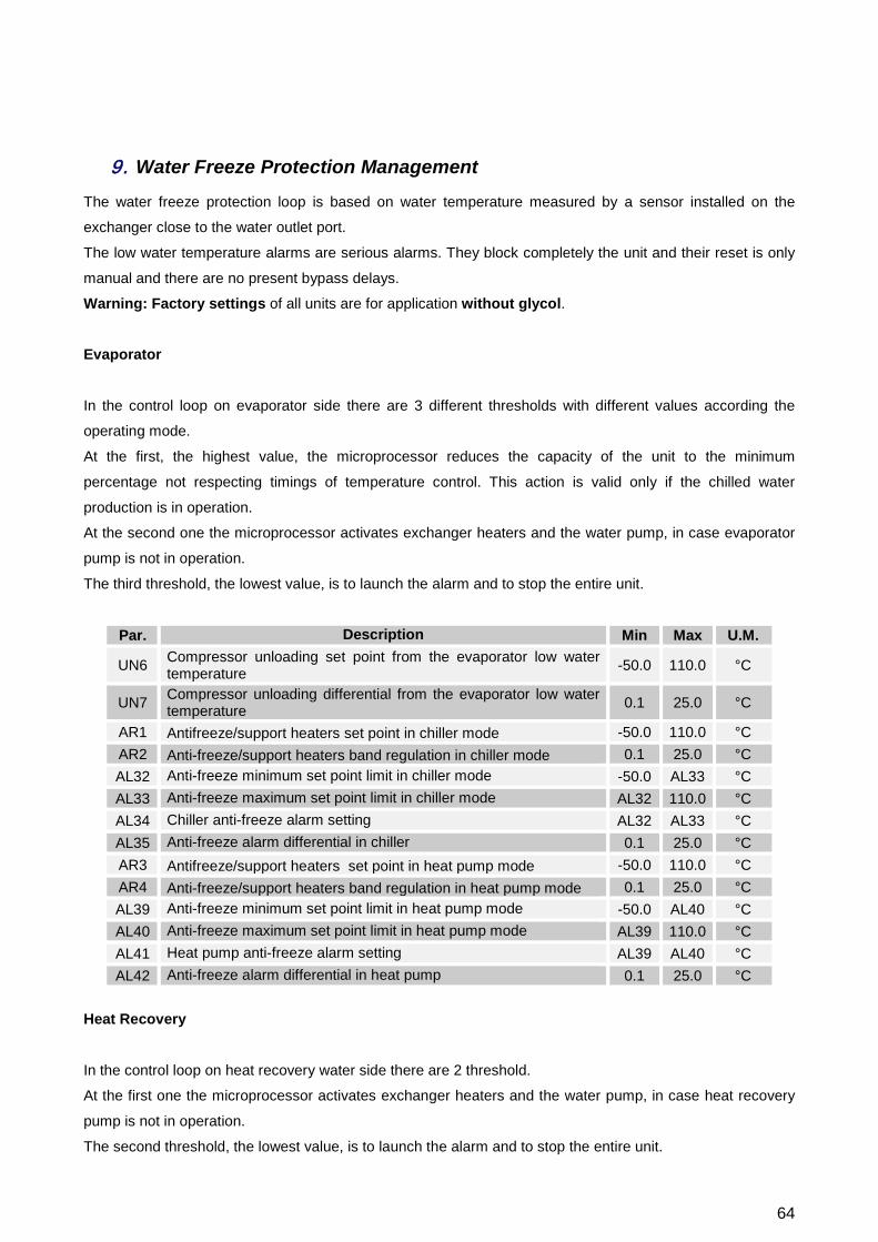
9. Water Freeze Protection Management
The water freeze protection loop is based on water temperature measured by a sensor installed on the
exchanger close to the water outlet port.
The low water temperature alarms are serious alarms. They block completely the unit and their reset is only
manual and there are no present bypass delays.
Warning: Factory settings of all units are for application without glycol. Evaporator
In the control loop on evaporator side there are 3 different thresholds with different values according the
operating mode.
At the first, the highest value, the microprocessor reduces the capacity of the unit to the minimum
percentage not respecting timings of temperature control. This action is valid only if the chilled water
production is in operation.
At the second one the microprocessor activates exchanger heaters and the water pump, in case evaporator
pump is not in operation.
The third threshold, the lowest value, is to launch the alarm and to stop the entire unit.
Par. Description Min Max U.M.
UN6 Compressor unloading set point from the evaporator low water temperature -50.0 110.0 °C
UN7 Compressor unloading differential from the evaporator low water temperature 0.1 25.0 °C
AR1 Antifreeze/support heaters set point in chiller mode -50.0 110.0 °C AR2 Anti-freeze/support heaters band regulation in chiller mode 0.1 25.0 °C AL32 Anti-freeze minimum set point limit in chiller mode -50.0 AL33 °C AL33 Anti-freeze maximum set point limit in chiller mode AL32 110.0 °C AL34 Chiller anti-freeze alarm setting AL32 AL33 °C AL35 Anti-freeze alarm differential in chiller 0.1 25.0 °C AR3 Antifreeze/support heaters set point in heat pump mode -50.0 110.0 °C AR4 Anti-freeze/support heaters band regulation in heat pump mode 0.1 25.0 °C AL39 Anti-freeze minimum set point limit in heat pump mode -50.0 AL40 °C AL40 Anti-freeze maximum set point limit in heat pump mode AL39 110.0 °C AL41 Heat pump anti-freeze alarm setting AL39 AL40 °C AL42 Anti-freeze alarm differential in heat pump 0.1 25.0 °C
Heat Recovery
In the control loop on heat recovery water side there are 2 threshold.
At the first one the microprocessor activates exchanger heaters and the water pump, in case heat recovery
pump is not in operation.
The second threshold, the lowest value, is to launch the alarm and to stop the entire unit.
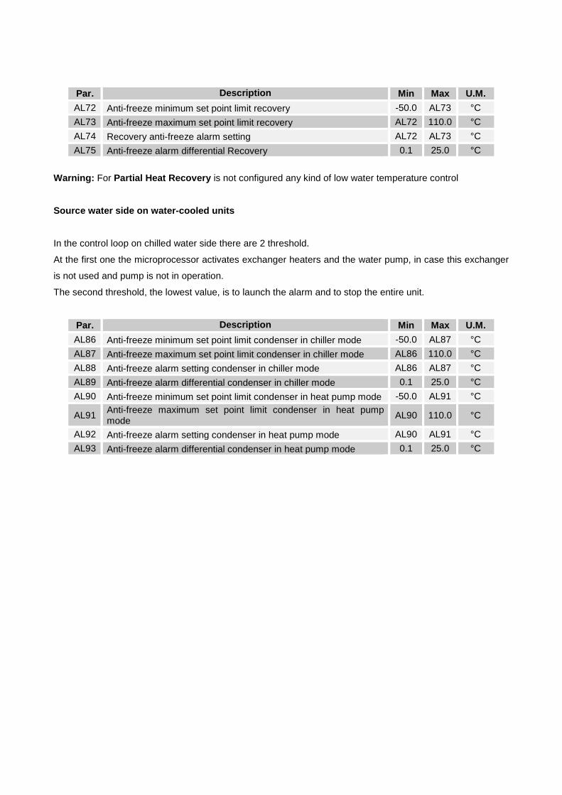
Par. Description Min Max U.M. AL72 Anti-freeze minimum set point limit recovery -50.0 AL73 °C AL73 Anti-freeze maximum set point limit recovery AL72 110.0 °C AL74 Recovery anti-freeze alarm setting AL72 AL73 °C AL75 Anti-freeze alarm differential Recovery 0.1 25.0 °C
Warning: For Partial Heat Recovery is not configured any kind of low water temperature control
Source water side on water-cooled units
In the control loop on chilled water side there are 2 threshold.
At the first one the microprocessor activates exchanger heaters and the water pump, in case this exchanger
is not used and pump is not in operation.
The second threshold, the lowest value, is to launch the alarm and to stop the entire unit.
Par. Description Min Max U.M. AL86 Anti-freeze minimum set point limit condenser in chiller mode -50.0 AL87 °C AL87 Anti-freeze maximum set point limit condenser in chiller mode AL86 110.0 °C AL88 Anti-freeze alarm setting condenser in chiller mode AL86 AL87 °C AL89 Anti-freeze alarm differential condenser in chiller mode 0.1 25.0 °C AL90 Anti-freeze minimum set point limit condenser in heat pump mode -50.0 AL91 °C
AL91 Anti-freeze maximum set point limit condenser in heat pump mode AL90 110.0 °C
AL92 Anti-freeze alarm setting condenser in heat pump mode AL90 AL91 °C AL93 Anti-freeze alarm differential condenser in heat pump mode 0.1 25.0 °C

66
10. Condensing Fans Management
Units could be equipped with fan management in order to control the condensing or evaporating pressure
according the operating mode.
Two different types are available related to the unit noise version and to the selected optional:
• Step control
• Continuous control.
Condensing Step Control
Par. Description Min Max U.M. FA10 Minimum fan speed setting in chiller mode / First step setting 0.0 50.0 bar FA11 Maximum fan speed setting in chiller mode / Second step setting 0.0 50.0 bar FA12 Proportional band regulation in chiller mode / Differential on circ.1 steps 0.1 14.0 bar FA13 CUT-OFF differential in chiller mode / Differential on circ.2 steps 0.1 14.0 bar FA25 Third step setting in chiller mode 0.0 50.0 bar FA26 Fourth step setting in chiller mode 0.0 50.0 bar FA27 Differential on circ.3 steps in chiller mode 0.1 14.0 bar FA28 Differential on circ.4 steps in chiller mode 0.1 14.0 bar
Evaporating Step Control
Par. Description Min Max U.M. FA19 Maximum fan speed setting in HP mode / Fourth step setting 0.0 50.0 bar FA20 Minimum fan speed setting in HP mode / Third step setting 0.0 50.0 bar FA21 Proportional band regulation in HP mode / Differential on steps of circ.1 0.1 14.0 bar FA22 CUT-OFF differential in HP mode / Differential on circ.2 steps 0.1 14.0 bar FA29 Second step setting in heat pump mode 0.0 50.0 bar FA30 First step setting in heat pump mode 0.0 50.0 bar FA31 Differential on circ.3 steps in HP mode 0.1 14.0 bar FA32 Differential on circ.4 steps in HP mode 0.1 14.0 bar

Warning: To avoid Configuration alarm n°2 it is necessary to respect these mathematics rules:
• FA10<FA11<FA25<FA26
• FA19<FA20<FA29<FA30
Continuous Condensing Control
Par. Description Min Max U.M. FA8 Minimum operation speed of the chiller fans 0 FA16 % FA9 Maximum operation speed of the chiller fans FA16 100 % FA10 Minimum fan speed setting in chiller mode / First step setting 0.0 50.0 bar FA11 Maximum fan speed setting in chiller mode / Second step setting 0.0 50.0 bar FA12 Proportional band regulation in chiller mode / Differential on circ.1 steps 0.1 14.0 bar FA13 CUT-OFF differential in chiller mode / Differential on circ.2 steps 0.1 14.0 bar FA14 CUT OFF over ride in chiller mode 0.1 14.0 bar FA16 Night function speed in chiller mode FA8 FA9 %
Continuous Evaporating Control

68
Par. Description Min Max U.M. FA17 Minimum fan speed in heat pump mode 0 70 % FA18 Maximum fan speed in heat pump mode 70 100 % FA19 Maximum fan speed setting in HP mode / Fourth step setting 0.0 50.0 bar FA20 Minimum fan speed setting in HP mode / Third step setting 0.0 50.0 bar FA21 Proportional band regulation in HP mode / Differential on steps of circ.1 0.1 14.0 bar FA22 CUT-OFF differential in HP mode / Differential on circ.2 steps 0.1 14.0 bar FA23 CUT OFF over ride in HP mode 0.1 14.0 bar FA24 Night function speed in HP mode 30 100 %
Warning: To avoid Configuration alarm n°2 it is necessary to respect these mathematics rules:
• FA10+FA12+FA13<FA11
• FA13<FA14
• FA19+FA22+FA21<FA20
• FA22<FA23
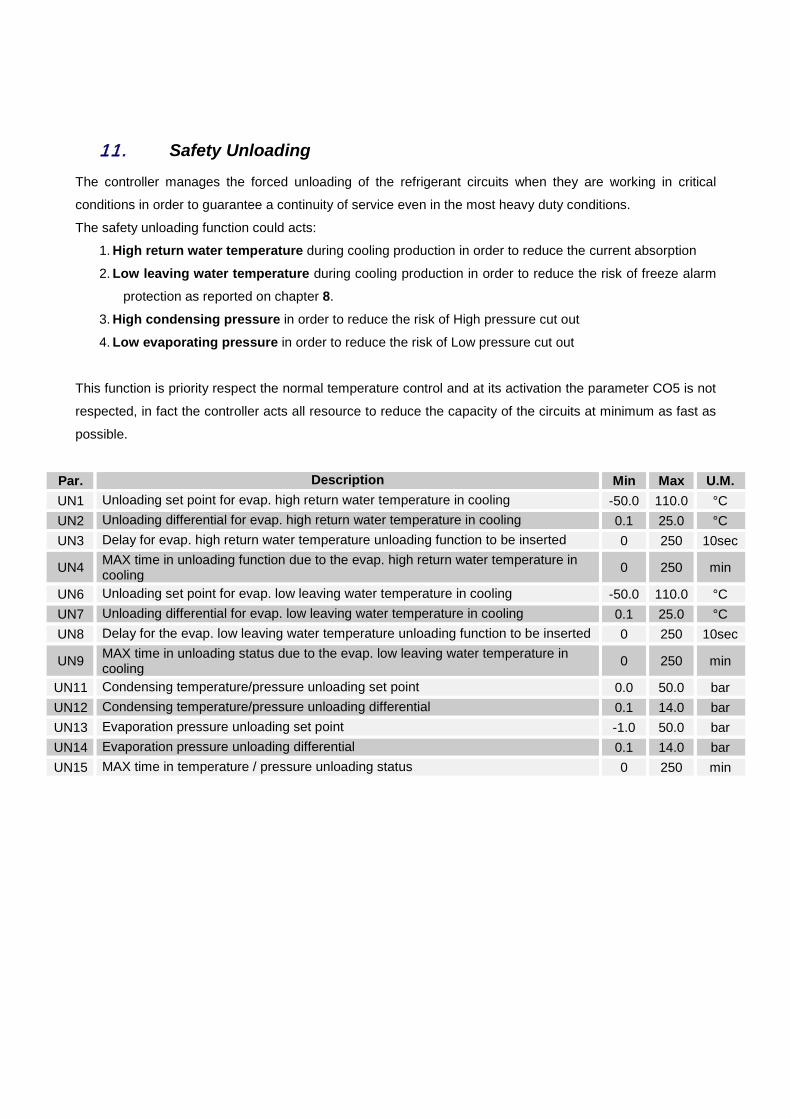
11. Safety Unloading
The controller manages the forced unloading of the refrigerant circuits when they are working in critical
conditions in order to guarantee a continuity of service even in the most heavy duty conditions.
The safety unloading function could acts:
1. High return water temperature during cooling production in order to reduce the current absorption
2. Low leaving water temperature during cooling production in order to reduce the risk of freeze alarm
protection as reported on chapter 8.
3. High condensing pressure in order to reduce the risk of High pressure cut out
4. Low evaporating pressure in order to reduce the risk of Low pressure cut out
This function is priority respect the normal temperature control and at its activation the parameter CO5 is not
respected, in fact the controller acts all resource to reduce the capacity of the circuits at minimum as fast as
possible.
Par. Description Min Max U.M. UN1 Unloading set point for evap. high return water temperature in cooling -50.0 110.0 °C UN2 Unloading differential for evap. high return water temperature in cooling 0.1 25.0 °C UN3 Delay for evap. high return water temperature unloading function to be inserted 0 250 10sec
UN4 MAX time in unloading function due to the evap. high return water temperature in cooling 0 250 min
UN6 Unloading set point for evap. low leaving water temperature in cooling -50.0 110.0 °C UN7 Unloading differential for evap. low leaving water temperature in cooling 0.1 25.0 °C UN8 Delay for the evap. low leaving water temperature unloading function to be inserted 0 250 10sec
UN9 MAX time in unloading status due to the evap. low leaving water temperature in cooling 0 250 min
UN11 Condensing temperature/pressure unloading set point 0.0 50.0 bar UN12 Condensing temperature/pressure unloading differential 0.1 14.0 bar UN13 Evaporation pressure unloading set point -1.0 50.0 bar UN14 Evaporation pressure unloading differential 0.1 14.0 bar UN15 MAX time in temperature / pressure unloading status 0 250 min
70
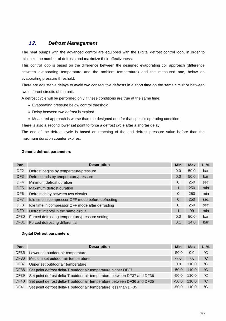
12. Defrost Management
The heat pumps with the advanced control are equipped with the Digital defrost control loop, in order to
minimize the number of defrosts and maximize their effectiveness.
This control loop is based on the difference between the designed evaporating coil approach (difference
between evaporating temperature and the ambient temperature) and the measured one, below an
evaporating pressure threshold.
There are adjustable delays to avoid two consecutive defrosts in a short time on the same circuit or between
two different circuits of the unit.
A defrost cycle will be performed only if these conditions are true at the same time:
• Evaporating pressure below control threshold
• Delay between two defrost is expired
• Measured approach is worse than the designed one for that specific operating condition
There is also a second lower set point to force a defrost cycle after a shorter delay.
The end of the defrost cycle is based on reaching of the end defrost pressure value before than the
maximum duration counter expires.
Generic defrost parameters
Par. Description Min Max U.M. DF2 Defrost begins by temperature/pressure 0.0 50.0 bar DF3 Defrost ends by temperature/pressure 0.0 50.0 bar DF4 Minimum defrost duration 0 250 sec DF5 Maximum defrost duration 1 250 min DF6 Defrost delay between two circuits 0 250 min DF7 Idle time in compressor OFF mode before defrosting 0 250 sec DF8 Idle time in compressor OFF mode after defrosting 0 250 sec DF9 Defrost interval in the same circuit 1 99 min
DF30 Forced defrosting temperature/pressure setting 0.0 50.0 bar DF31 Forced defrosting differential 0.1 14.0 bar
Digital Defrost parameters
Par. Description Min Max U.M. DF35 Lower set outdoor air temperature -50.0 0.0 °C DF36 Medium set outdoor air temperature -7.0 7.0 °C DF37 Upper set outdoor air temperature 0.0 110.0 °C DF38 Set point defrost delta-T outdoor air temperature higher DF37 -50.0 110.0 °C DF39 Set point defrost delta-T outdoor air temperature between DF37 and DF36 -50.0 110.0 °C DF40 Set point defrost delta-T outdoor air temperature between DF36 and DF35 -50.0 110.0 °C DF41 Set point defrost delta-T outdoor air temperature less than DF35 -50.0 110.0 °C

13. Energy Saving and Auto On / Off
The Energy Saving is the function to “reset” the water set points to save energy in particular conditions of
plant requests.
There are two different ways to activate this function:
1. Using Time slots
2. Using digital inputs (called commonly Double set point)
To use this function according the mode 1, it is necessary to set the time slots within the sub-menu “Time bands” as reported on Chapter 3.4.2, and to set, in the parameter group ES, the amount to “add” to the set
points and the value of the unit regulation band when this function is in operation.
This parameters shall be set also to use the mode 2.
Par. Description Min Max U.M. ES14 Increasing value of chilled water set point in Energy
Saving mode -50.0 110.0 °C
ES15 Chilled water regulation band in Energy saving mode 0.1 25.0 °C ES16 Increasing value of hot water set point in Energy
Saving mode -50.0 110.0 °C
ES17 Hot water regulation band in Energy saving mode 0.1 25.0 °C
The second mode is priority respect the mode 1.
To enable the Auto On/Off, it is sufficient to set the time slots within the sub-menu “Time bands” as
reported on Chapter 3.4.2.
72
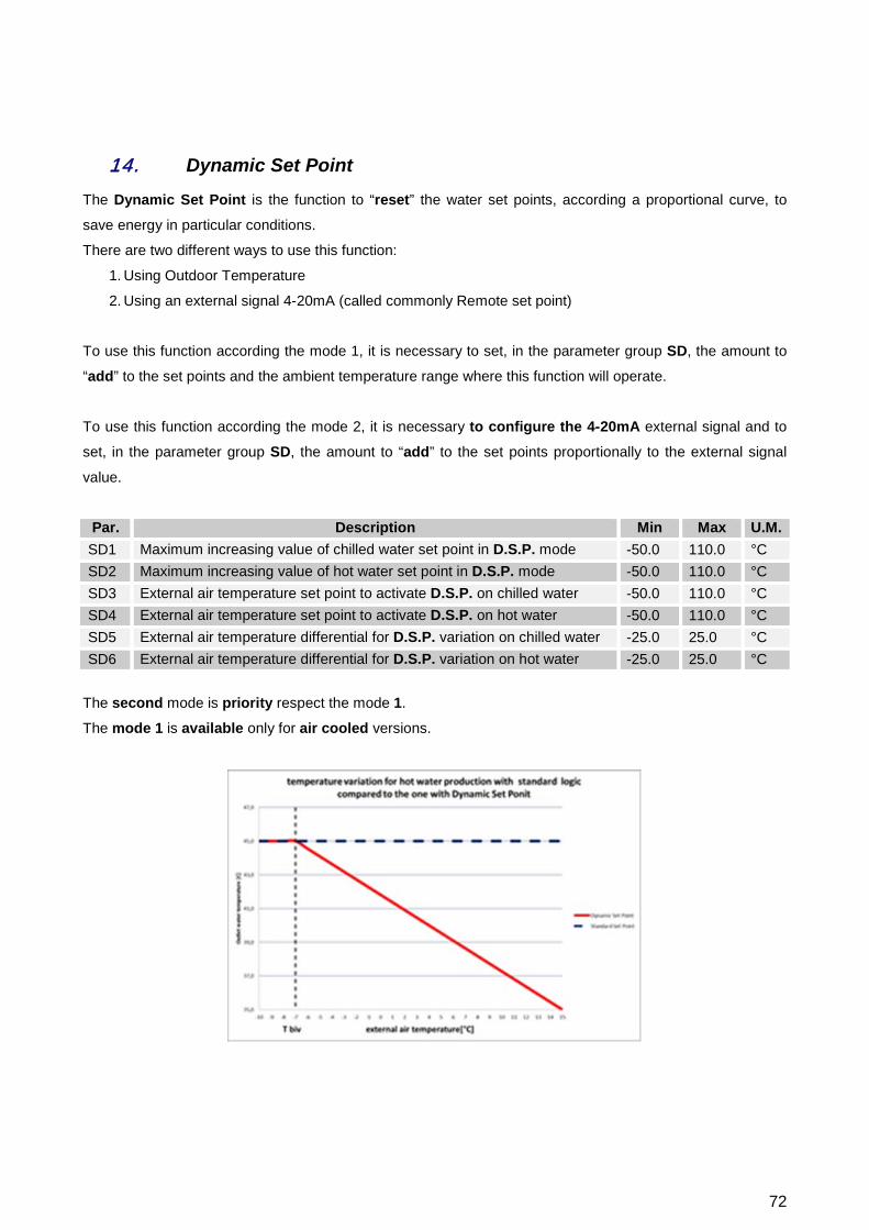
14. Dynamic Set Point
The Dynamic Set Point is the function to “reset” the water set points, according a proportional curve, to
save energy in particular conditions.
There are two different ways to use this function:
1. Using Outdoor Temperature
2. Using an external signal 4-20mA (called commonly Remote set point)
To use this function according the mode 1, it is necessary to set, in the parameter group SD, the amount to
“add” to the set points and the ambient temperature range where this function will operate.
To use this function according the mode 2, it is necessary to configure the 4-20mA external signal and to
set, in the parameter group SD, the amount to “add” to the set points proportionally to the external signal
value.
Par. Description Min Max U.M. SD1 Maximum increasing value of chilled water set point in D.S.P. mode -50.0 110.0 °C SD2 Maximum increasing value of hot water set point in D.S.P. mode -50.0 110.0 °C SD3 External air temperature set point to activate D.S.P. on chilled water -50.0 110.0 °C SD4 External air temperature set point to activate D.S.P. on hot water -50.0 110.0 °C SD5 External air temperature differential for D.S.P. variation on chilled water -25.0 25.0 °C SD6 External air temperature differential for D.S.P. variation on hot water -25.0 25.0 °C
The second mode is priority respect the mode 1.
The mode 1 is available only for air cooled versions.
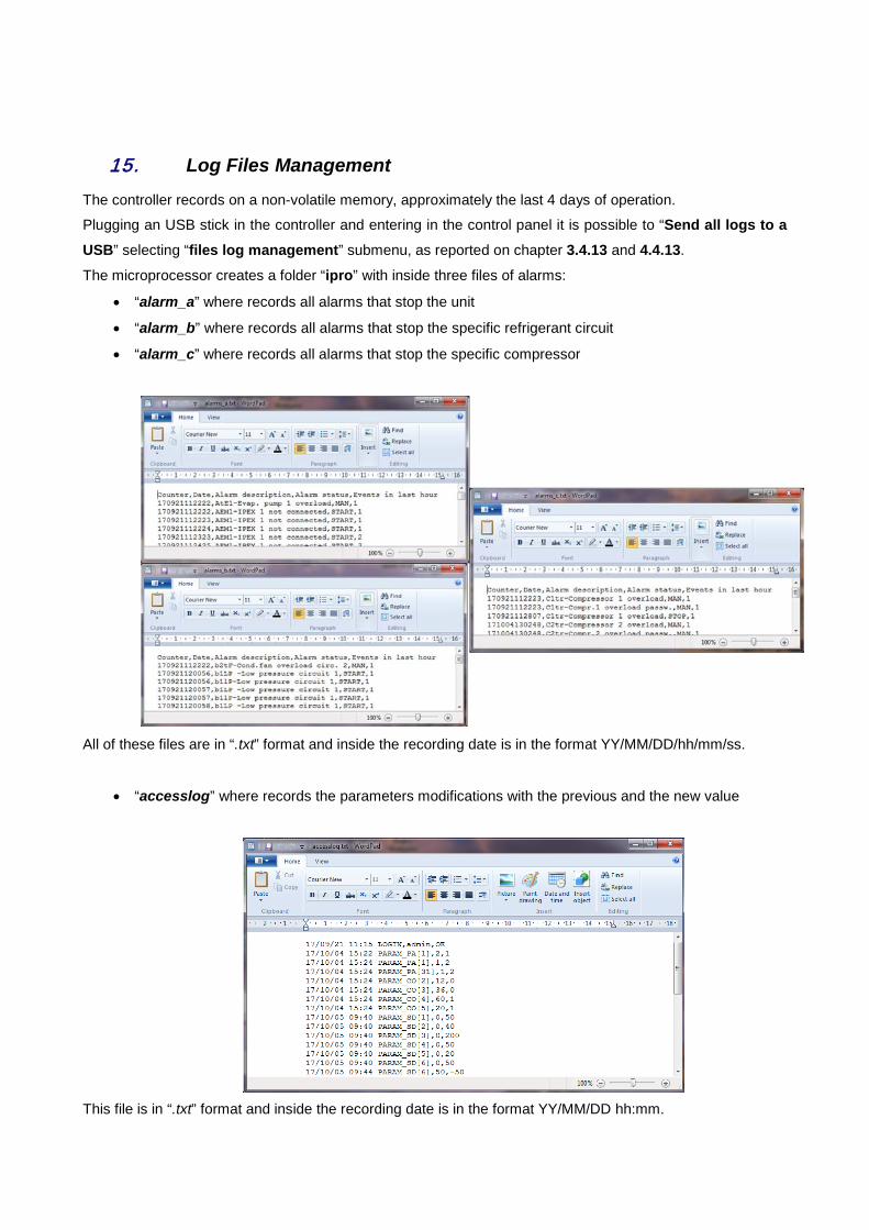
15. Log Files Management
The controller records on a non-volatile memory, approximately the last 4 days of operation.
Plugging an USB stick in the controller and entering in the control panel it is possible to “Send all logs to a USB” selecting “files log management” submenu, as reported on chapter 3.4.13 and 4.4.13.
The microprocessor creates a folder “ipro” with inside three files of alarms:
• “alarm_a” where records all alarms that stop the unit
• “alarm_b” where records all alarms that stop the specific refrigerant circuit
• “alarm_c” where records all alarms that stop the specific compressor
All of these files are in “.txt” format and inside the recording date is in the format YY/MM/DD/hh/mm/ss.
• “accesslog” where records the parameters modifications with the previous and the new value
This file is in “.txt” format and inside the recording date is in the format YY/MM/DD hh:mm.

74
• “Unit10Din” where records the last 4 days of operation with status and value of the main variables
This file is in “.txt” format and inside the recording date is in the format YY/MM/DD/hh/mm/ss.
Warning: Before log files download make sure that into the USB stick there is no folder named “ipro”.

16. Remote Control
To control the unit remotely are available different ways:
• Free contacts reported in customer terminal block (X);
• Bus protocol;
• Remote keypad
16.1. Remote Control via Free Contacts
In the electrical cabinet, on the customer terminal block (X) are present dry contacts where it is possible to
connect:
• To the unit
o Remote General On/Off
o Remote Summer/Winter mode selection
o Flow switches status
o Water pumps alarm status (external hydraulic groups)
o Digital input for Double set point
o Analog input for External set point
• From the unit
o Generic alarm status
o Water pumps enabling commands
o Unit status
In the unit wiring diagram is reported the contacts list with the terminal strips number.

76
16.2. Remote Control via Bus Protocol
Chillers and heat pumps with the advanced control can be integrated in a Building Automation System via
MODbus® RTU, LonTalk®, or BACnet® MSTP or IP.
All info necessary for the integration of the units are reported in the “Integration Guide” starting from the
manual code: MU–COMM–E–EL–REV2.0.1–1017–UK.
16.3. Control via Remote Keypad It is possible to connect a second keypad in parallel to the one of the unit as the connection diagram below.
Wrong wiring may cause serious damage to the keypads or controller. It should be necessary an updating of the keyboard once connected the second one as reported on chapter
3.4.13.
Trane optimizes the performance of homes and buildings around the world. A business of Ingersoll Rand, the leader in creating and
sustaining safe, comfortable and energy efficient environments, Trane offers a broad portfolio of advanced controls and HVAC systems, comprehensive building services, and parts. For more information, visit www.Trane.eu. Trane has a policy of continuous product and product data improvement and reserves the right to change design and specifications without notice. © 2018 Trane All rights reserved PROD-SVU001A-GB_0418 New