controllers for bd compressors - nidec … · controllers for bd compressors ... starting current...
TRANSCRIPT

www.secop.com
CONTROLLERS FORBD COMPRESSORS
NIDEC GLOBAL APPLIANCE
OPERATING INSTRUCTIONS (BD P-Housing)101N0212 Standard, 12/24 V DC 101N0340 AEO, 12/24 V DC101N0390 High Speed, 12/24 V DC101N0420 Solar, 10-45 V DC101N0510 AC/DC, 12/24 V DC, 100-240V AC101N0650 Automotive, 12/24 V DC

OperatingInstructions
2 3
1. Introduction ...........................................................................3 1.1 Applications ..................................................................3 1.3 Functions ......................................................................3
2. Technical data & specifications ............................................4 2.1 Technical data ...............................................................4 2.2 Specifications ...............................................................4
3. Wiring ...........................................................................5 3.1 Wiring diagram ............................................................5 3.2 Wiring diagram .............................................................5 3.3 Wiring diagram .............................................................5 3.4 Wire dimensions ...........................................................6
4. Menu overview ......................................................................7 4.1 User interface ...............................................................7 4.2 Operation ......................................................................7
5. Parameters ...........................................................................8 Discription of parameters ......................................................8
6. Battery protection ........................................................... 9-10 6.1 Solar mode .................................................................10
7. Compressor speed ..............................................................11 7.1 Compressor speed control modes ...........................12 7.1.1.1 Speed control Mode 1 ...............................................12 7.1.1.2 Speed control Mode 1 ......................................... 12-13 7.1.2 Speed control Mode 2 ...............................................14 7.1.3 Speed control Mode 3 ...............................................14 7.1.4 Speed control Mode 4 ...............................................14 7.2 Compressor min. and max. speed protection ..........15
8. Condenser fan ...............................................................16
9. Thermostat ...................................................................17 9.1 Thermostat type ...................................................17 9.1.1 Electronic thermostat (NTC sensor) ....................17 9.1.2 Mechanical thermostat ........................................17 9.2 Thermostat delays ................................................17
10. Communication .............................................................18 Lost communication ......................................................18 Node Number ................................................................18 Protection of settings.....................................................18
11. Product information .......................................................19
12. Error and Event Log ......................................................20 12.1 Actual Error ..........................................................20 12.2 Error Log ..............................................................20 12.3 Event Log ..............................................................20
13. Inverter temperature (PCB) .........................................21
14. Ordering ...................................................................22
15. One wire/LIN gateway...................................................23 MODBUS Parameter identification sheme............. 24-27
16. Installation of software.................................................28 Install and configure software ................................. 28-29 Install product key .........................................................30 Connect network ...................................................... 31-32 Ready to operate ............................................................33
TABLE OF CONTENTS

OperatingInstructions
2 3
1.INTRODUCTION
The BD35F, BD35K, BD50F, BD80CN, BD100CN and BD250GH.2 compressor systems are mainly introduced for mobile refrigerators and freezers. The operating conditions are Low/Medium/High Back Pressure (LBP/MBP/HBP). The system is able to operate in ambient temperatures up to +55 ºC (131 °F).All electronic units are HST types (High Starting Torque) except 101N0420 (Solar).
Typical applications for the electronic units are:• Truck refrigerators and freezers• Boat refrigerators and freezers• Bus refrigerators and freezers• Portable boxes• Solar cabinets• Agriculture• RVThe 101N0212 controller is intended for a variety of DC-powered applications, while the 101N0650 is intended for automotive applications, where requirements to EMI and leakage current are important.101N0340 is mainly intended for condensing units or systems with bigger load variations. It replaces the controllers 101N0300/320/330. 101N0390 is intended for BD80F, BD100CN, and BD250GH.2.101N0420 is intended for direct solar driven applications and replaces 101N0400 and 101N0410101N0510 is the new AC/DC unit and replaces 101N0500
The main functions of the controllers are:• Motor / Compressor speed control• Thermostat control (ON / OFF or electronic via NTC temperature sensor)• ECO function to optimize compressor speed for minimum power consumption• Fan control• Error LED• Communication interface• Monitoring function• Error & event log• Battery protection functions• Main Switch• Log of specific parameters via Tool4Cool® software• Optimization of specific parameters via PC software before commencing mass production• Parameter setting via PC or resistors• AEO (Adaptive Energy Optimizing) in selected models (101N0340, 101N0390 and 101N0420)
1.1Applications
1.2Functions

OperatingInstructions
4 5
2.1Technical data
2.2Specifications
Below is a list of key parameters of the new electronic units (controllers).
2. TECHNICAL DATA &SPECIFICATIONS
Input voltage 9.0-32 V DC | 10-45 V DC (Solar unit) | 100 -240 V AC (AC/DC unit)
Min./max. operating temperature -10 to +55 °C
External fuse required 15 A @ 12 V, 7.5 A @ 24 V, slow blow type
Starting current 15 A @ 12 V, 7.5 A @ 24 V
Leakage current 101N0212/340/390/420/510 <= 4 mA @ 12 V, < 6 mA @ 24 V
Leakage current 101N0650 <= 150 μA @ 12 V, < 170 μA @ 24 V
EMC approval 101N0212/340/390/420/510Compliant to 2004/104/EC (e-marking)EC declaration 2004/108/ECCISPR 25 Class 1CISPR 14
EMC approval 101N0650
Compliant to 2004/104/EC (e-marking)EC declaration 2004/108/ECCISPR 25 Class 4 in all operating modesCISPR 25 Class 5 except 80-82 Mhz radiated emission with 12 V supply at 3500 rpm
NTC type to be connected Epcos M800/5K
Fan output5 W, nominal voltage 12 V• Use a fan with over/undervoltage protection• A 12 V fan must also be used in 24 V systems
Test name Standard Conditions
Temperature shock VW 801 01: 2009-03 sec 5.2.2 -40/+105 °C, 10 sec, 75 cyc/min., 300 cyc
Vibration Freightliner Eng Std 49-00085 5-500 Hz, 4 g, X-Y-Z axis, 3x3 h each
Salt Mist VW 801 01: 2009-03 sec 5.5.4 Powered, 1 of 8 hours running, 6x8 h spray on/16 h off, 5 % NaCL, 35 °C, 1-2 ml/80 cm3/h
Corrosion ASTM G85 Annex 5 0.05 % NaCL + 0.35 % ammonia sulphate, 35 °C, 6 h of 1 h on/1 h off repeated
Gas exposure 6h, 75 % RH, 0.5 % H2S + 0.5 % SO3
Thermal cycling with humidity EN60068-2-35 test Db -10/+55 °C, 97 % RH, 3 weeks,
compressor running intermitting
Storage VW 801 01: 2009-03 sec 5.1.1 +90 °C 96 h, -40 °C 24 h
IP test EN 60529 Edition 2.1 2001-02 Min. IP 20
Free fall IEC 60068-2-32 1 m, concrete, 2 times 2 sides
Thermography 0/60/60 °C max. speed, solder below 110 °C, components acc. to Nidec GA Compressors derating guideline
Thermal performanceSteady state: 15/60/60 °C @ 2000, 10/60/60 °C @ 2500, 5/60/60 °C @ 3000, 0/60/60 °C @ 3500.Pull down, 5 min. without cutout: 15/70/60 °C @ 2000, 15/70/60 °C @ 3500.

OperatingInstructions
4 5
3.1Wiring diagram101N0212, 101N340, 101N0390, 101N0650
3.2Wiring diagram101N0420
3.3Wiring diagram101N0510
3.WIRING

OperatingInstructions
6 7
The compressor control units have the following connections:
-, + Main supply voltage. Nominal voltage 12 V DC and 24 V DC, range: 9.0 to 32 V DC.
+, F Fan connection, max. 5 W, connect always 12 V fan (even in 24 V systems).
D/I: Connect either an Error LED between + and D/I for a simple error indication. The Error LED will be driven with 10 mA constant current. Or connect communication interface (Tool4Cool® gateway or customer controller like display) between D/I and C.
P, C Connect a battery protection resistor to select the required battery cut out value. See table at chapter 6, Battery programming, on page 9.
C+T Connect either a mechanical thermostat, a mechanical thermostat in series with a speed programming resistor or a NTC temperature sensor. See chapter 7, Speed control modes on page 12.
L, N Main supply voltage, voltage range 100-240 V AC 50/60 HzA, C Lamp connection (max. 5 W, connect always 12 V)
The above mentioned maximum wire length ensures sufficient low voltage drop during start and operation. Thinner wires may cause unintended low voltage battery cut-outs due to low voltage at the electronic unit, despite the voltage at the battery still being in an acceptable range.
Size Max length*12 V DC operation
Max. length*24 V DC operation
AWGGauge
Cross section
mm2ft. m ft. m
12 2.5 8 2.5 16 5
11 4 13 4 26 8
10 6 20 6 39 12
8 10 33 10 66 20
* Length between battery and electronic unit
Wire dimensions ACCross section min. 0.75 mm2 or AWG 18
101N0212, 101N340, 101N0390, 101N0420, 101N0650
101N0510
3.4Wire dimensions101N0212, 101N340, 101N0420, 101N0510, 101N0650
Wire dimensions101N0390 Size Max length*
12 V DC operationMax. length*
24 V DC operation
AWGGauge
Cross section
mm2ft. m ft. m
10 6 8 2.5 16 5
* Length between battery and electronic unit

OperatingInstructions
6 7
Operation of the Compressor control unit can be done through the PC software Tool4Cool®
An example of the menu structure is shown below. It may vary depending on the controller model.
On the following pages each separate menu is explained in detail.For installation and operation of Tool4Cool®, please refer to Chapter 15 Installation of the software on page 26.
The Tool4Cool® software enables the user to observe and document certain aspects of the compressor operation via the controller. The output of the software is in the form of data logs and plots.
Using Tool4Cool® the user can also change the settings of the controller parameters, and copy settings from one controller to another.
4.1User interface
4.2Operation
4. MENU OVERVIEW

OperatingInstructions
8 9
Main Switch Function
In order to start and stop the compressor the Main Switch can be set to ON or OFF.OEMs making an interface with custom design electronics via Modbus must be able to control the CCU ON/OFF via the Main Switch (CCU = Compressor Control Unit).
ON: All functions are active.OFF: All main functions are inactive, however• Battery monitoring active• NTC temperature sensor monitoring active• PCB inverter temperature monitoring active
Settings
Beside the “Main Switch” parameter a “default main switch” parameter is available. This parameter defines, how the main switch will be set after a power supply interruption.
For standalone systems without a customer specific controller (e.g. display) it’s recommended to have this “default main switch” set to 1 (ON) which is also the default. This way the unit will automatically continue to run after a power interruption.
For systems using a customer specific controller (e.g. display), it should be set to 0 (OFF) to ensure, that the compressors stays off even after a power down/up, if the communication line is interrupted.
Name Default Max. value Min. value Step Unit
Main switch ON ON OFF 1 -
Default main switch ON OFF ON 1 -
Discription of parameters
5. PARAMETERS

OperatingInstructions
8 9
The battery protection prevents permanent damage to the battery by discharge.
The setting range is 9-17 V DC for 12 V DC systems, and 19 to 27 V DC for 24 V DC systems.The cut out values and cut in differences can be set individual for 12 V systems and 24 V systems. Battery protection function is disabled in Solar controller 101N0420 (fixed range 10 to 45 V DC).
If the voltage remains below the cut-out voltage for the time specified in the parameter “Cut-out delay” (default 3s), compressor and fan are stopped.
Compressor and fan are stopped immediately, if the voltage drops below 8 V in 12 V systems and below 18 V in 24 V systems (critical stop).
If Solar mode is enabled, the electronic will be able to run over the entire input voltage range (9-32 V), without stopping between 12 V and 24 V range.
Tolerances are ± 0.30 V DC.
Settings
Name Default Max value Min value Step Unit
Battery cutout level 12 V DC 10.4 17 9 0.1 Volt
Battery cut-in diff. 12 V DC 1.3 10 0.5 0.1 Volt
Battery cut-out level 24 V DC 22.8 32 19 0.1 Volt
Battery cut-in diff. 24 V DC 1.3 10 0.5 0.1 Volt
Battery Solar mode on/off Disable Enable Disable - -
Cutout delay 3 60 0 1 Seconds
6. BATTERY PROTECTION
ON
OFF
OFF
ONAlarm state
Comp. state
Cut-out level
Cut-in level
Max limit 32 V DC
0-60 sec 60-120 sec
Battery Protection
Critical stop 8 V/18 V DC
(Restart delay)(Cut-outdelay)
(Voltage failure)

OperatingInstructions
10 11
Measurements
In order to let the compressor run on solar panels, the solar mode should be enabled. The solar mode can be enabled either with Tool4Cool® or with a 220 kOhm resistor between C and P. With solar mode enabled, the battery protection settings will not stop the compressor between 12 V and 24 V voltage range, but let it run over the entire voltage range from 9 to 32 V DC.The above mentioned is not valid for dedicated Solar controller 101N0420 which can run from 10 to 45 V DC.
Settings
To program the battery cut out value, either Tool4Cool® can be used or a resistor can be connected between C and P. See R2 in chapter 3.1 and 3.2, wiring diagrams on page 5.
Not valid for Solar controller 101N0420 (10 to 45 V DC)
Name Default Max value Min value Step Unit
Battery Solar mode on/off Disable Enable Disable - -
6.1Solar mode
6.2Battery programming resistor
Name Note Unit
Voltage cut-out level Only show in Solar Mode Volt
Battery cut-in level In Solar Mode change text to voltage cut-in level Volt
Supply voltage Measured on + and - terminals Volt
Resistor (R2) kΩ 12 V cut-out [V] 12 V cut-in [V] 12 V max. [V] 24 V cut-out [V] 24 V cut-in [V] 24 V max. [V]
0 9.6 10.9 17.0 21.3 22.7 31.5
1.6 9.7 11.0 17.0 21.5 22.9 31.5
2.4 9.9 11.1 17.0 21.8 23.2 31.5
3.6 10.0 11.3 17.0 22.0 23.4 31.5
4.7 10.1 11.4 17.0 22.3 23.7 31.5
6.2 10.2 11.5 17.0 22.5 23.9 31.5
11 10.5 11.8 17.0 23.0 24.5 31.5
14 10.6 11.9 17.0 23.3 24.7 31.5
18 10.8 12.0 17.0 23.6 25.0 31.5
24 10.9 12.2 17.0 23.8 25.2 31.5
33 11.0 12.3 17.0 24.1 25.5 31.5
47 11.1 12.4 17.0 24.3 25.7 31.5
82 11.3 12.5 17.0 24.6 26.0 31.5
220 9.6 10.9 31.5

OperatingInstructions
10 11
The speed and thereby the capacity of the compressor is set using the Requested speed parameter. During start up, the compressor runs at a lower speed, Start speed (fixed 2500 rpm) , than Requested speed. The duration of the period running at Start speed is set using the Start time (min. 30 sec, adjustable to 0 sec in 101N0420) parameter.
If the compressor speed drops below the minimum or exceeds the maximum speed, the compressor will stop and an alarm Min speed failure or Max. speed failure will be sent. The compressor will try to restart after the set Restart time. The Restart time default is 60 secThe fans will continue to run.
7.COMPRESSOR SPEED
Temp.
Cut-in temp.
Cut-out temp.
Compressor speed
Start speed
Start timeStart delay
Requested speed4000
3500
3000
2500
2000
0

OperatingInstructions
12 13
The speed and capacity can be controlled in four ways:1) mechanical thermostat with speed control resistor2) mechanical thermostat and speed set via Tool4Cool® / communication interface3) NTC and ECO speed set via Tool4Cool® / communication interface4) NTC and fixed speed set via Tool4Cool® / communication interface
Mechanical Thermostat and Resistor SpeedIn Speed control mode 1, the speed can be set via an external resistor in series with the mechanical Thermostat (see chapter 3, page 5, Wiring diagram). Alternatively, a constant current or a PWM signal (open collector, 5kHz +-5%) can be used to control the speed. For details of the speed, please refer to the following table:
Mechanical Thermostat and Resistor Speed (no resistor in AEO mode)In Speed control mode 1, the speed can be set via an external resistor in series with the mechanical Thermostat (see chapter 3, page 5, Wiring diagram). Alternatively, a constant current or a PWM signal (open collector, 5kHz +-5%) can be used to control the speed.
If no resistors are connected between C and T, speed control is done by AEO. The AEO function can be adapted via four setpoint parameters:
• AEO Runtime setpoint: The target runtime for the compressor during cut-in
• AEO Start speed at power up: The start speed of compressor in AEO mode, overruled by fixed speed with 2500 rpm for 30 sec
• AEO Max. ramp up time: The maximum time that the speed is ramping up before reaching maximum speed for the compressor (3500 rpm for 101N0340 and 4400 rpm for 101N0390)
• AEO Reduction of next start speed: The parameter defines how much the next start speed shall be reduced at next thermostat cut-in
For details of the speed, please refer to the following tables on the next page.
7.1Compressor speed control modes
7.1.1.1Speed control Mode 1101N0212, 101N0650, 101N0510
7.1.1.2Speed control Mode 1101N0340, 101N0390, 101N0420
101N
0212
101N
0510
101N
0650
Motor speed [rpm] Resistor R1 [Ohm]
2000 0
2500 277
3000 692
3500 1523

OperatingInstructions
12 13
101N
0340
101N
0420
wit
h A
EO
Motor speed [rpm] Resistor R1 [Ohm]
AEO 0
2000 173
2500 450
3000 865
3500 1696
101N
0390
wit
h A
EO
Motor speed [rpm] Resistor R1 [Ohm]
AEO 0
2500 203
3100 451
3800 867
4400 1700

OperatingInstructions
14 15
Mechanical Thermostat and Tool4Cool® SpeedIn Speed control mode 2, the speed can be set via Tool4Cool® or any customer specific controller (e.g. a display). To set the compressor speed, enter the required speed into the field “requested compressor speed”.The Compressor On / Off state is still controlled via a mechanical thermostat. Alternatively it can also be controlled via Tool4Cool® or any customer specific controller (e.g. a display). This would be done via the “thermostat forced on” parameter.
NTC and ECO Speed“NTC and ECO speed set via Tool4Cool® / communication interface” would be used if a NTC is used to control the temperature inside the cabinet. This is the most advanced function of the new controllers. The compressor speed is automatically adapted to the current cooling requirement.
Operation in ECO mode reduces energy consumption and noise by controlling compressor speed as a function of temperature. The Eco Temperature is automatically calculated to be in the middle between cut in temperature and cut out temperature:• when operating below ECO temperature, compressors run at the set ECO speed (often 2000 rpm)• when operating above ECO temperature, the compressors run at Requested speed (often 3500 rpm)
The temperatures can be adjusted in the “Thermostat” section within Tool4Cool®.
NTC and fixed speedNTC with fixed speed is used, if the ECO function is not required. The compressor is running with the fixed speed, set via Tool4Cool®.The NTC temperatures for cut in and cut out can be set in the thermostat section within Tool4Cool®.
7.1.2Speed control Mode 2
7.1.3Speed control Mode 3
7.1.4Speed control Mode 4
4000
3500
3000
2500
2000
Compressor speed
NTC thermostat temperature
5
4
3
2
1
0
-1
-2
-3
rpm
Max speed
Start speed
ECO speed
Cut-in temp
ECO temp
Cut-out temp
C°

OperatingInstructions
14 15
Settings 101N0212/101N340/101N420/101N510/101N650
Settings 101N0390
Measurement
The compressor is protected against operation below minimum speed. Lubrication of the compressor will be very poor at excessively low speed and therefore low speed operation would lead to destruction of the compressor. Speed limits are: min 1850 rpm; max speed 3750 rpm.
Name Description Step Unit
Compressor speed Real-time compressor speed (+/-10 %) 1 rpm
Name Default Max value Min value Step Unit
Requested speed 2000 3500 2000 10 rpm
Start delay 2 240 0 1 Seconds
Start speed 2500 2500 2500 1 rpm
Start time 30 240 30 1 Seconds
7.2Compressor min. and max. speed protection
Min. & Max. Compressor Speed Protection
Max. speed 3750 rpm (4650 rpm for 101N0390)
Min. speed 1850 rpm(2350 rpm for101N0390)
Comp. state
Alarm state
ON
OFF
OFF OFF
ON (Min speed failure) ON (Max speed failure)
60-120 sec (Restart delay)60-120 sec (Restart delay)
Name Default Max value Min value Step Unit
Requested speed 2500 3500 2000 10 rpm

OperatingInstructions
16 17
The fan is synchronized with the compressor operation.Start and stop delays can be set up as a function of the state of the thermostat.Furthermore, the fan can be set to run continuously (forced ON operation).Some fan defects are detectable, and are displayed in the parameter Error.The fan start and stop delays start after the thermostat delays have passed. Please see chapter 9.2 on page 15, Thermostat delays.
Settings
Measurements
Name Description Step Unit
Fan speed Actual fan speed - %
Name Default Max value Min value Step Unit
Fan start delay 0 240 0 1 Seconds
Fan stop delay 0 240 0 1 Seconds
Fan forced ON OFF ON OFF 1 -
8.CONDENSER FAN
Condenser fan

OperatingInstructions
16 17
Two types of thermostat can be utilized for temperature control.
The electronic thermostat provides active temperature control. With an NTC sensor the cabinet temperature can be measured constantly by the compressor electronic. If a customer controller (display) is used, it can just sent the desired temperature to the compressor controller and the compressor controller will regulate the compressor operation automatically according to the demand.Disconnected sensor error alarm (NTC sensor failure) is sent when the measured temperature is > 85 °C.Short circuited sensor error alarm (NTC sensor failure) is sent when the measured temperature < -50 °C.
A mechanical ON/OFF thermostat can be connected at terminals C & T. No detection of faulty thermostat is provided when an ON/OFF thermostat is used.
In order to prevent the compressor from accidentially starting and stopping due to a flickering Thermostat, a delay can be added. This delay can be especially useful on bumpy roads. The default on delay is one second, the default off delay is zero second.
In general, there are three on- and off-delays built into the electronic: a) Thermostat on- and off-delayb) Compressor on- and off-delayc) Fan on- and off-delay
The compressor is started after the thermostat has closed and thermostat on-delay plus compressor on-delay have elapsed.The fan is started after the thermostat has closed and thermostat on-delay plus fan on-delay have elapsed.
A Thermostat on and off event is only logged, once the corresponding Thermostat delay is elapsed. Therefore it is generally recommended, to set the thermostat delay as high as acceptable for the user.
Settings
Measurements
Name Default Max value Min value Step Unit
Cutout temperature 4 + 40 -40 1 Celcius (ºC)
Difference 2 15 1 1 Kelvin (K)
Forced ON OFF ON OFF 1 -
Name Description Step Unit
Runtime Runtime is provided to record cooling-time (ther-mostat cut-in period). The runtime is updated during cooling, starting with 0 at start of each cooling period.During cooling OFF (Thermostat cut-out), the Runtime parameter will show the time for the last cooling period. Runtime is reset at the be-ginning of a cooling ON period, and at power-up.
1 Minutes
Actual temperature Real-time air temperature when a NTC sensor is used. When a mechanical thermostat is used, only thermostat status ON or OFF is displayed.
- ºC
9.THERMOSTAT
9.1Thermostat type
9.1.1Electronic thermostat (NTC sensor)
9.1.2Mechanical thermostat
9.2 Thermostat delays

OperatingInstructions
18 19
In a network system with custom designed interface modules acting as master on the Modbus, it is desirable to stop the compressor from running when communication to the master is lost.
If communication is lost it will not be possible for the customer to stop the compressor as long as cooling is requested.
The function will stop the compressor after a certain time (Communication time out), when there is no contact to the master controller. The stop is realized through the MainSwitch. The Main Switch will be set to OFF.
If the power gets disconnected, the main switch will be set to "Default Main Switch after power up" (see section Main Switch on page 5).
If a customer specific controller (e.g. display) is used, it is recommended to set "Default Main Switch after up" to 0 (OFF) and "Set Main Switch to OFF when communication timeout occurs" to 1 (ON).
Name Default Max value Min value Step Unit
Bus address 1 247 1 1 -
Communication timeout 900 7200 15 1 Seconds
Protection code 0 9999 0 1 -
Name Default Max value Min value Step Unit
Protection status 0 1 0 1 on/off
10.COMMUNICATION
Lost Communication
Bus addresses
Protection code
The node number is the adress of the electronic. If mulitple compressor electronics are used with one customer controller in one network, each compressor electronic must have its unique Node Number.
A coded privacy function protects customers’ settings from being read by third parties.The code must be verified by entering twice.
Settings
Mesurements

OperatingInstructions
18 19
11.PRODUCT INFORMATION
Labels on electronic units consist of a 2D Data Matrix Code area and a number of lines with information. The 2D Data Matrix Code is always built up with 62 characters containing information about type, code number, product version, product revision, unit ID, supplier, part number and text.
Text information on the label:Line 1: ID: PLYYWWssssss (unique number)Line 2: Date: YYWWLine 3: Ver.: VVLine 4: Text: text
Meaning:PL Production location, 01 … 99YY Year, 12 = 2012WW Week number, 01 … 52ssssss Serial number, 000001 … 999999VV Version, 00 … 99
Settings
Name Description
Unit name Possible to fill in customer name for the unit when presented in PC software program Tool4cool®.
Measurements
Name Description
Product code no. Nidec GA Compressors product code number
Firmware version Controller software version
Production date Nidec GA Compressors production date

OperatingInstructions
20 21
12. ERROR AND EVENT LOG
The alarm function notifies the user when an error arises in the system, and implements measures which prevent damage to the refrigeration system.This parameter is on view in all parameter groups.
Output
These error codes can also be read out via an Error LED, connected between + and D/I. See Chapter 3 on page 5.
In order to assist in service and fault situations, an error log is implemented in ECU, the log isread out via Tool4Cool®. The log contains Errors and the sequence of their occurrence. Additionally, they are linked to the Event log.
Each error contains the following information:• Time of occurrence related to compressor power up, with 1 sec as sample time• The sequence of occurrence (Error list reference)• Error main description• SubError description • Number of occurrence possible to clear the error log via a clear function.
In order to assist in service and fault situations, an event log is implemented in ECU, the log is read out via Tool4Cool®. The log contains parameters and events when parameter changes and on Power up.
Each event contains the following information:• Time of occurrence related to compressor power up, with 1 sec as sample time• The sequence of occurrence (Event list reference)• Parameter/Event description• The value of the parameter• Number of occurrence (when no value is related to the parameter)• The value of the parameter which caused the failure (if connected to a parameter); it is possible to clear the event log via a clear function.
Name Description
Actual error
0 = No error1 = Voltage failure2 = Fan failure3 = Motor failure4 = Speed failure5 = Thermal failure6 = NTC sensor failure7 = Communication error
12.1 Actual Error
12.2 Error log
12.3 Event log

OperatingInstructions
20 21
13 .INVERTER TEMPERATURE (PCB)
The controller overheating protection system ensures that the controller does not operate atextremely high temperatures, because under these conditions the quality of the soldered joints will be endangered.
When the unit reaches 110 ºC the system will shut down and an alarm error (Alarm 6: Thermal failure) will be sent.
The system restarts automatically after the temperature has dropped below 100 ºC. Hereafter the set delay Compressor restart delay must be terminated. The default duration is 60 sec.
Electronic Unit Over-Temperature Protection
100°C
110°C
Inverter temp.
(Restart delay)60-120 sec
ON
OFF
OFF
ONAlarm state
Comp. state
(Thermal failure)

OperatingInstructions
22 23
14.ORDERING
ModelCode
numberDescription
Com
pres
sors
BD35F 101Z0200 standard version
BD35F 101Z0204 inch connectors
BD35F-B 101Z0205 noise improved version for busses and trucks
BD35F-HD 101Z0206 heavy duty version for trucks with chassis mounted
BD50F 101Z1220 standard version
BD50F 101Z0203 inch connectors
BD80F 101Z0280 standard version
BD35K 101Z0211 standard version
BD80CN 101Z0403 standard version
BD100CN 101Z0401 standard version
BD250GH.2 101Z0406 standard version, 2nd generation improved in cooling capacity and COP
Sing
le-P
ack
Electronic unit Standard, 12/24 V DC 101N0212 controller
Electronic unit AEO, 12/24 V DC 101N0340 controller
Electronic unit High Speed, 12/24 V DC 101N0390 controller
Electronic unit Solar, 10-45 DC 101N0420 controller
Electronic unit AC/DC, 12/24 V DC, 100-240V AC 50/60Hz 101N0510 controller
Electronic unit Automotive, 12/24 V DC 101N0650 controller
Temperature sensor, 470 mm, spade connectors 105N9612 accessories
Temperature sensor, 1000 mm, spade connectors 105N9614 accessories
Temperature sensor, 1500 mm, spade connectors 105N9616 accessories
Secop One Wire/LIN gateway with cables & driver 105N9501 accessories
Indu
stri
al-P
ack
(I-P
ack)
Electronic unit Standard, 12/24 V DC 101N0213 controller, 30 pcs
Electronic unit AEO, 12/24 V DC 101N0341 controller, 30 pcs
Electronic unit High Speed, 12/24 V DC 101N0391 controller, 30 pcs
Electronic unit Solar, 10-45 DC 101N0421 controller, 30 pcs
Electronic unit AC/DC, 12/24 V DC, 100-240V AC 50/60Hz 101N0511 controller, 28 pcs
Electronic unit Automotive, 12/24 V DC 101N0651 controller, 30 pcs
Temperature sensor, 470 mm, spade connectors 105N9613 accessories, 200 pcs
Temperature sensor, 1000 mm, spade connectors 105N9615 accessories, 100 pcs
Temperature sensor, 1500 mm, spade connectors 105N9617 accessories, 100 pcs
Soft
war
e P
acka
ge
Tool4Cool® LabEditionfree of charge
www.secop.com/solutions/application-detail/variable-speed-drive-software-tool4cool/
Dri
ver
Virtual COM Port Driver for Wire/LIN Gateway(Future Technology Devices International Ltd.) www.ftdichip.com/Drivers/VCP.htm

OperatingInstructions
22 23
Gateway 105N9501 package contains:Pos. Description
1 USB 2.0 A/B Cable
2 One Wire/LIN Gateway Communication Cable 105N9532
3Secop One Wire/LIN GatewayLength, Height: 55 mm / Width: 82 mm / Depth: 80 mm
Please install the latest Virtual COM Port Driver from Future Technology Devices International Ltd.:www.ftdichip.com/Drivers/VCP.htm
15.ONE WIRE/LIN GATEWAY

24 25
MODBUS Parameter identification MODBUS Parameter identification
Register number Group name & parameter text
Setting or
measurementDefault setting Min. Value Max. value Unit
shown in T4C EEPROM Note
Main functions. Menu level 1 Main functions. Menu level 135401 Main switch Setting ON OFF ON See also “default main switch”.
35402 Default Main switch Setting ON OFF ON X Defines the value of mainswitch parameter 35401 after reset.
Battery protection. Menu level 1 Battery protection. Menu level 1.35324 Battery cut-out level 12 V DC Setting 10.4 9 17 V X Hide in Solar Mode.
35325 Battery cut-in difference 12 V DC Setting 1.3 0.5 10 V X In Solar Mode change from setting to measurement. Change text from Battery cut-in difference to Voltage cut-in difference.
35326 Battery cut-out level 24 V DC Setting 22.8 19 32 X Hide in Solar Mode
35327 Battery cut-in difference 24 V DC Setting 1.3 0.5 10 V X In Solar Mode change from setting to measurement. Change text from Battery cut-in difference to Voltage cut-in difference.
35303 Battery cut-out delay Setting 3 0 600 sec X Valid during start up and normal operation.
35330 Solar Mode Setting Disable Disable Enable X Voltage range is 9.6 to 32 V DC when enabled.
35304 Voltage cut-out level Measurement V Only show in Solar Mode.
Battery cut-in level Measurement V In solar mode change text to Voltage cut in level.
35400 Supply voltage Measurement V Measured on + and - terminals.
Compressor. Menu level 1 Compressor. Menu level 1
35101 Speed control mode Setting 1 1 4 X1 = Mech thermostat and speed via resistor 2 = Mech thermostat and speed via T4C 3 = NTC and ECO mode 4 = NTC and speed via T4C
35001 Requested compressor speed Setting 2000 rpm 2000 rpm 3500 rpm rpm X Overruled by resistor in series with thermostat in speed mode 1. Hide in speedmode 1.
35111 Requested ECO speed Setting 2000 rpm 2000 rpm 3500 rpm rpm X Overruled by resistor in series with thermostat in speed mode 1.
35002 Compressor start delay Setting 2 0 240 sec X The time that the compressor should wait after sp voltage above min stop.
35029 Compressor stop delay Setting 0 0 240 sec X The time that the compressor should wait after sp voltage above min stop.
35004 Compressor start speed Setting 2500 rpm 2500 rpm 2500 rpm rpm Fixed 2500 rpm.
35005 Compressor start time Setting 30 30 240 sec X Adjustable to min. 0 sec in 101N0420
35151 AEO Runtime setpoint Setting 30 15 240 min. X The target runtime for the compressor during cut-in
35152 AEO Start speed at power up Setting 2600 2000 3500 rpm X The start speed of compressor in AEO mode, overruled by fixed speed with 2500 rpm for 30 sec
35153 AEO Max. ramp up time Setting 60 15 150 min. X The maximum time that the speed is ramping up before reaching maximum speed for the compressor (3500 rpm for 101N0340 and 4400 rpm for 101N0390)
35154 AEO Reduction of next start speed Setting 300 100 1000 rpm X The parameter defines how much the next start speed shall be reduced at next thermostat cut-in
35098 Compressor speed Measurement rpm
35113 Compressor runtime Measurement min. Cut-in time will show the time for the last cooling period (thermostat cut-in period). Compressor runtime is reset at every start of cooling ON period.
Thermostat. Menu level 1 Thermostat. Menu level 135102 Cut-out temperature Setting 4 -40 40 °C X
35103 Cut-in difference Setting 2 1 15 K X
35104 Thermostat Forced ON Setting Disabled Disabled Enabled X
35403 Thermostat cut in delay Setting 2 0 90 sec X Thermostat filter, e.g. For Tilt sensor filtering.
35404 Thermostat cut out delay Setting 0 0 90 sec X Thermostat filter, e.g. For Tilt sensor filtering.
35200 NTC thermostat temperature / Thermostat Measurement °C Real time air temperature when a NTC sensor is used. When a mechanical thermostat is
used, only thnermostat status ON or OFF is displayed.
Fan control. Menu level 1 Fan control. Menu level 135203 Fan start delay Setting 0 0 240 Sec X Delay compared to thermostat status
35204 Fan stop delay Setting 0 0 240 Sec X Delay compared to thermostat status
35205 Forced ON Setting Disabled Disabled Enabled X
35300 Fan speed Measurement 0 100 %
Compressor safety. Menu level 2. Advanced functions Communication. Menu level 2. Advanced functions35003 Compressor restart time Setting 60 60 120 sec X The time that the unit should wait before attempting a restart, after an error has occured.
Communication. Menu level 2. Advanced functions Communication. Menu level 2. Advanced functions35901 Node number Setting 1 1 250 X Can be changed without restarting the electronic unit.
35903 Set Main Switch to OFF when communication timeout occurs Setting 0 0 1 X 0 = Function disabled.
1 = Set Main Switch to OFF when communication timeout occurs.
35904 Communication timeout Setting 900 15 7200 sec X
35905 Protection code Setting 0 0 9999 XWriting: When locking the unit, the code should be written twice to verify. When unlocking the unit, the code should only be written once.
1/2

26 27
MODBUS Parameter identification MODBUS Parameter identification
Register number Group name & parameter text
Setting or
measurementDefault setting Min. Value Max. value Unit
shown in T4C EEPROM Note
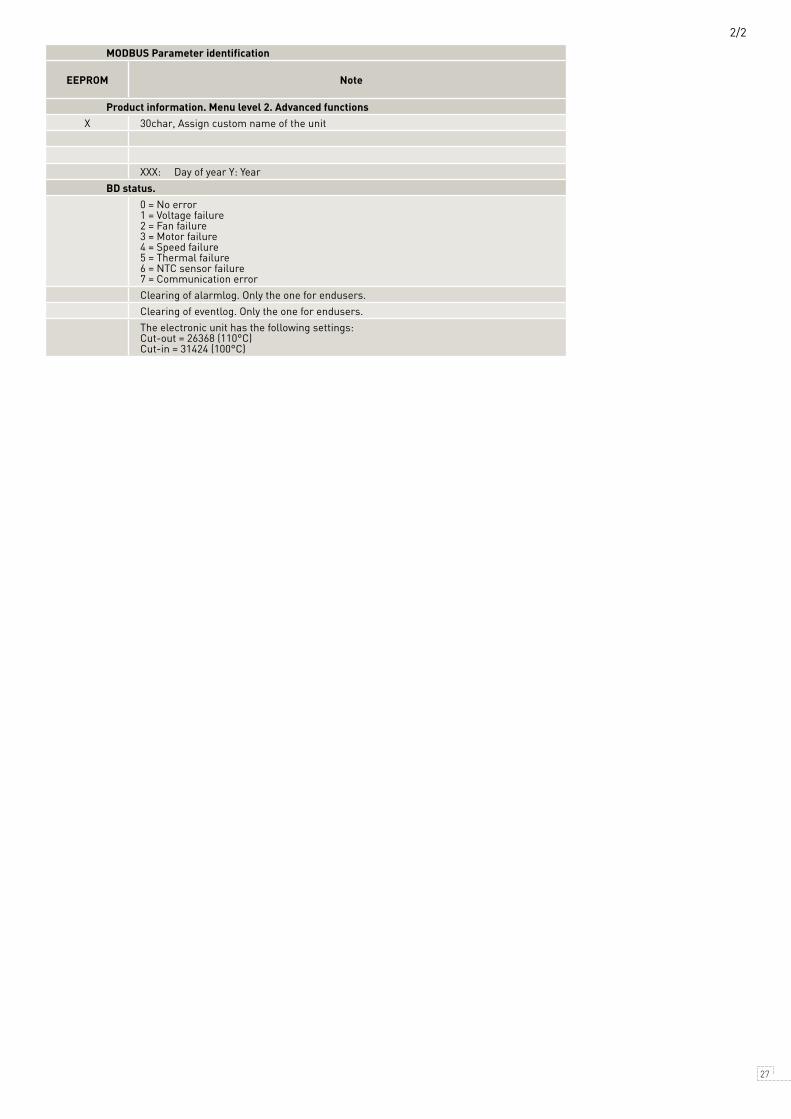
Product information. Menu level 2. Advanced functions Product information. Menu level 2. Advanced functionsUnit name Setting Characters X 30char, Assign custom name of the unit
Product code Measurement 101N0XXX 0 0 0
Software version Measurement 01.00 0 999
Production date Measurement XX-YY 0 99999 1 XXX: Day of year Y: Year
BD status. BD status.
35100 Actual error Measurement 0 8
0 = No error 1 = Voltage failure 2 = Fan failure 3 = Motor failure 4 = Speed failure 5 = Thermal failure 6 = NTC sensor failure 7 = Communication error
35868 Clear alarmlist Setting 0 0 1 Clearing of alarmlog. Only the one for endusers.
35867 Clear eventlist Setting 0 0 1 Clearing of eventlog. Only the one for endusers.
35099 PCB temperature Measurement °CThe electronic unit has the following settings: Cut-out = 26368 (110°C) Cut-in = 31424 (100°C)
26 27
MODBUS Parameter identification MODBUS Parameter identification
Register number Group name & parameter text
Setting or
measurementDefault setting Min. Value Max. value Unit
shown in T4C EEPROM Note
Product information. Menu level 2. Advanced functions Product information. Menu level 2. Advanced functionsUnit name Setting Characters X 30char, Assign custom name of the unit
Product code Measurement 101N0XXX 0 0 0
Software version Measurement 01.00 0 999
Production date Measurement XX-YY 0 99999 1 XXX: Day of year Y: Year
BD status. BD status.
35100 Actual error Measurement 0 8
0 = No error 1 = Voltage failure 2 = Fan failure 3 = Motor failure 4 = Speed failure 5 = Thermal failure 6 = NTC sensor failure 7 = Communication error
35868 Clear alarmlist Setting 0 0 1 Clearing of alarmlog. Only the one for endusers.
35867 Clear eventlist Setting 0 0 1 Clearing of eventlog. Only the one for endusers.
35099 PCB temperature Measurement °CThe electronic unit has the following settings: Cut-out = 26368 (110°C) Cut-in = 31424 (100°C)
2/2

OperatingInstructions
28 29
1) Visit: https://www.secop.com/solutions/application-detail/variable-speed-drive-software-tool4cool/ and download the latest Tool4Cool® version2) Open the download.
Install and configure software
16.INSTALLATION OF SOFTWARE

OperatingInstructions
28 29
3. Double-click Tool4Cool® Software Installation. Run the file setup.exe. Then follow the instructions in the Setup Wizard.
For detailed instructions please refer to Tool4Cool® LabEdition Operating Instructions.This manual can be downloaded from the Tool4Cool® homepage:
Latest Virtual COM Port Driver for Wire/LIN Gateway from Future Technology Devices International Ltd.:http://www.ftdichip.com/Drivers/VCP.htm
1 2
3 4
5

OperatingInstructions
30 31
1. Start Tool4Cool® LabEditon by double clicking on the icon on the desktop:
2. Select Help in the menu bar.
3. Select Product Keys from the drop-down menu:
4. This dialog box will open:
In the Add Product Key field, type the Product Keys shown on the Tool4Cool® Homepage:https://www.secop.com/solutions/application-detail/variable-speed-drive-software-tool4cool/Click the Add Product Key button, to add it to the list.The Product Key is now listed in the Active product keys list.
Install product key

OperatingInstructions
30 31
1. Select File in the menu bar.
2. Select Connect Network in the drop-down menu:
3. This dialog box will open:
Connect network
In the Connect using field, select the COM port to which the gateway is connected.
Press the configure button and select:– first network node = 1– last network node = 3– refresh rate = 3Close the configure network dialog with OK.

OperatingInstructions
32 33
Close the connect network dialog with OK.
Wait a short time. The LEDs on the gateway will flash, then a red arrow will appear in front of the description (COM1). The controller is now accessible via Tool4Cool®.

OperatingInstructions
32 33
Click the red arrows to view the controller and its parameter groups:
Click a parameter group name to view details to the right of the screen:
Ready to operate

34 35
NOTES

34 35
NOTES

www.secop.com
TOOL4COOL® SOFTWARE – FLEXIBLE CONTROL SETTINGS
TOOL4COOL® is a unique PC software tool that enables you to precisely configure your Secop compressors to your cooling systems. Via microprocessor-based controllers, TOOL4COOL® gives you easy access to all parameters. These can be changed, monitored, downloaded or uploaded to get the optimum performance out of your cooling system.TOOL4COOL® covers a wide range of applications within parking cooling, light commercial cooling and transport cooling and much more. Using TOOL4COOL®, you can determine the basic specifications of your product, giving you the ability to clearly differentiate yourself in the market.
OUR JOURNEY SO FAR
1958Start of production for PW compressors.
1972Introduction of FRcompressors.
1993Start of production with natural refrigerant R600a (isobutane).Production facility in Crnomelj, Slovenia founded.
2008Production facilityin Wuqing, Chinafounded.
1970Introduction of SC compressors.The birth of a standard-setting platform in the light commercial market.
1990Introduction of NLcompressors.
2002Production facility in Zlate Moravce, Slovakia founded.
2010Introduction SLV-CNK.2 and SLV-CLK.2 variable speed compressors.Introduction BD1.4F Micro DC compressor.Introduction of DLX and NLU compressors.
2015New generation of energy-efficient propane compressors.New variable speed platforms for household and light commercial applications.
1956Production facility and headquarters in Flensburg, Germany founded.
1999Start of production with natural refrigerantR290 (propane).
1977Introduction TL and BD compressors.
1992Introduction of PLcompressors.
2005Introduction of GScompressors.
2013Introduction of the XV compressor - opening a new chapter in refrigeration history.Secop acquires ACC Fürstenfeld,Austria.
Low HighCooling Capacity
HOUSEHOLD
LIGHT COMMERCIAL
DC-POWERED
P-Series
AC
DC
T-Series DELTA X-Series D-Series KAPPA
BDT-Housing
BDP-Housing
BD Micro
N-Series F-Series S-Series G-Series
Flexible control settings
TOOL COOL4
Produced by Nidec Global Appliance Germany GmbH | July 2016 DES.S.100.F2.02
Nidec GA Compressors accepts no responsibility for possible errors in catalogs, brochures, and other printed material. Nidec GA Compressors reserves the right to alter its products without notice.This also applies to products already on order provided that such alterations can be made without subsequential changes being necessary to specifications already agreed. All trademarks in thismaterial are the property of the respective companies. Secop and the Secop logotype are trademarks of Nidec Global Appliance Germany GmbH. All rights reserved.
Nidec Global Appliance Germany GmbH · Mads-Clausen-Str. 7 · 24939 Flensburg · Germany · Tel: +49 461 4941 0 · www.secop.com