controlling dc motors with the l298n dual h-bridge...arduino will give you the ability to control...
TRANSCRIPT

Controlling DC Motors with the L298N Dual H-Bridge
DroneBot Workshop Tutorial
https://dronebotworkshop.com

For more projects and tutorials visit the DroneBot Workshop - https://dronebotworkshop.com
Table of Contents
DC Motors 2 How DC Motors Work 3 Pulse Width Modulation (PWM) 5 H-Bridge 7 The L298N H-Bridge 9 L298N Module Pinouts 11 Breadboard Experiments 14 Using an Arduino with the L298N 18 Adding Speed Controls 27 Control with a Joystick 33 Summary 45
https://dronebotworkshop.com 1
For more projects and tutorials visit the DroneBot Workshop - https://dronebotworkshop.com
If you plan on working with robots or just building things that move you’ll eventually
need to learn how to control a DC motor. The inexpensive L298N H-Bridge module is a
simple way to achieve that. Coupling the L298N H-Bridge to a microcontroller like an
Arduino will give you the ability to control both the speed and rotation direction of two
DC motors.
In this article and it’s accompanying video I’ll show you everything you need to know to
start adding some motion to your next Arduino project. So let’s get moving!
DC Motors
The first practical DC (Direct Current) motor was invented by the British scientist William
Sturgeon in 1832. Since then DC motors have been part of countless pieces of
equipment and machinery.
Today DC motors range from huge models used in industrial equipment to tiny devices
that can fit in the palm of your hand. They are inexpensive and are ideal for use in your
Robotics, Quadcopter and Internet of Things projects.
Unlike LED’s you can’t just connect a DC motor to one of the output pins of your
Arduino or Raspberry Pi and expect it to work. DC motors have current and voltage
requirements that are beyond the capabilities of your microcontroller or microcomputer.
It is necessary to use some external electronics to drive and control the motor, and
you’ll probably need a separate power supply as well.
There are a number of ways to drive a DC motor from the output of your computing
device. A single transistor can be used to drive a DC motor, this works well providing
you do not need to change the direction that the motor is spinning.
https://dronebotworkshop.com 2

For more projects and tutorials visit the DroneBot Workshop - https://dronebotworkshop.com
A more versatile way of controlling a DC motor is to use a circuit called an “H-Bridge”.
An “H-Bridge” is an arrangement of transistors that allow you to control both the
direction and speed of the motor. Today we’ll examine a very common H-Bridge module
based around the L298N integrated circuit.
How DC Motors Work
In a simple DC motor there are two main components, the “stator” and the “armature”.
The stator is a permanent magnet and provides a constant magnetic field. The
armature, which is the rotating part, is a simple coil.
The armature is connected to a DC power source using a 2-piece ring installed around
the motor shaft, these ring sections are called “commutator rings”. The two pieces of the
commutator rings are connected to each end of the armature coil. Direct Current of a
suitable voltage is applied to the commutator rings via two “brushes” that rub against the
rings.
When DC is applied to the commutator rings it flows through the armature coil,
producing a magnetic field. This field is attracted to the stator magnet (remember,
opposite magnetic polarities attract, similar ones repel) and the motor shaft begins to
spin.
The motor shaft rotates until it arrives at the junction between the two halves of the
commutator. At that point the brushes come into contact with the other half of the
commutator rings, reversing the polarity of the armature coil (or coils, most modern DC
motors have several). This is great because at this point the motor shaft has rotated 180
degrees and the magnetic field polarities need to be reversed for the motor to continue
rotating. This process repeats itself indefinitely until current is removed from the
armature coils.
https://dronebotworkshop.com 3

For more projects and tutorials visit the DroneBot Workshop - https://dronebotworkshop.com
The motor I have just described is referred to as a brushed DC motor because
(obviously) it has brushes. Brushes however create many problems – they can start to
wear over time, they rub against the motor shaft and they can even cause sparking as
the motor gets older.
Better quality DC motors are the brushless variety. Brushless motors use a more
complex arrangement of coils and do not require a commutator. The moving part of the
https://dronebotworkshop.com 4

For more projects and tutorials visit the DroneBot Workshop - https://dronebotworkshop.com
motor is connected to the permanent magnet. Because they do not contain brushes
these brushless motors will last longer and are also much quieter than brushed DC
motors. Most quadcopter Motors are brushless motors.
DC motors are specified by the voltage level at which they operate. Common hobbyist
motors run at 6 Volts or 12 volts DC.
To reverse the direction in which the DC motor rotates you simply reverse the polarity of
the DC current that you apply to it. Changing the speed however is a different story.
One method of changing the speed of a DC motor is to simply reduce its supply voltage.
While this will work to some degree it is actually not a very good method of controlling
motor speed as lowering the voltage will also lower the torque that the motor is capable
of producing. Also, once the voltage drops below a certain point the motor will not rotate
at all.
Pulse Width Modulation (PWM)
A far better method of controlling DC motors is to use pulse width modulation or PWM.
If you’ve read up on controlling LEDs with your microcontroller you probably have
already run into PWM as it’s also a good method of controlling the brightness of an
LED.
With PWM the motor is sent a series of pulses. Each pulse is of the full voltage that the
motor can handle so a 6-volt motor will be sent 6 volt pulses while a 12-volt motor will
be sent 12 volt pulses. The width of the pulses are varied to control the motor speed,
pulses with a narrow width will cause the motor to spin quite slowly. Increasing the
pulse width will increase the speed of the motor, as illustrated below.
https://dronebotworkshop.com 5

For more projects and tutorials visit the DroneBot Workshop - https://dronebotworkshop.com
In order to stop the motor completely you just stop pulsing it, essentially sending it zero
volts. To run it at full speed you send it the full voltage, again without pulsing it.
https://dronebotworkshop.com 6

For more projects and tutorials visit the DroneBot Workshop - https://dronebotworkshop.com
You can build a simple PWM generator using a 555 timer and discrete components but
it’s a lot easier to use an Arduino. The Arduino has a function called “analogWrite”
which is used to drive any of its PWM-capable outputs (the Arduino Uno has 6 digital
outputs that are also capable of PWM).
H-Bridge
Now that you know how DC motors work, how you can reverse their direction by
changing polarity and how you can change their speed using pulse width modulation,
let’s examine an easy way to do this using a very common circuit configuration called an
“H-Bridge”.
An “H-Bridge” is simply an arrangement of switching the polarity of the voltage applied
to a DC motor, thus controlling its direction of rotation. To visualize how this all works I’ll
use some switches, although in real life an H-Bridge is usually built using transistors.
Using transistors also allows you to control the motor speed with PWM, as described
above.
In the first diagram we can see four switches which are all in the open or “off” position.
In the center of the circuit is a DC motor. If you look at the circuit as it is drawn here you
can distinctly see a letter “H”, with the motor attached in the center or “bridge” section –
thus the term “H-Bridge”.
https://dronebotworkshop.com 7

For more projects and tutorials visit the DroneBot Workshop - https://dronebotworkshop.com
If we close (i.e. turn on) two of the switches you can see how the voltage is applied to
the motor, causing it to turn clockwise.
https://dronebotworkshop.com 8

For more projects and tutorials visit the DroneBot Workshop - https://dronebotworkshop.com
Now we’ll open those switches and close the other two. As you can see this causes the
polarity of the voltage applied to the motor to be reversed, resulting in our motor
spinning counterclockwise.
This is pretty simple but effective. In fact if all you need to do is design a circuit to drive
the motor full-speed in either direction you could actually build this as shown here, using
a 4PDT (4 Pole Double-Throw) center-off switch. But of course we want to control the
motor using an Arduino, so an electronic circuit where the switches are replaced by
transistors is what we need.
The L298N H-Bridge
While you can use discrete transistors to build an H-Bridge there are a number of
advantages in using an integrated circuit. A number of H-Bridge motor driver IC’s are
https://dronebotworkshop.com 9
For more projects and tutorials visit the DroneBot Workshop - https://dronebotworkshop.com
available and all of them work in pretty much the same fashion. One of the most popular
is the L298N.
The L298N is a member of a family of IC’s that all have the designation “L298”. The
difference between the family members is in the amount of current they can handle. The
L298N can handle up to 3 amperes at 35 Volts DC, which is suitable for most hobby
motors.
The L298N actually contains two complete H-Bridge circuits, so it is capable of driving a
pair of DC motors. This makes it ideal for robotic projects, as most robots have either
two or four powered wheels. The L298N can also be used to drive a single stepper
motor, however we won’t cover that configuration in this article.
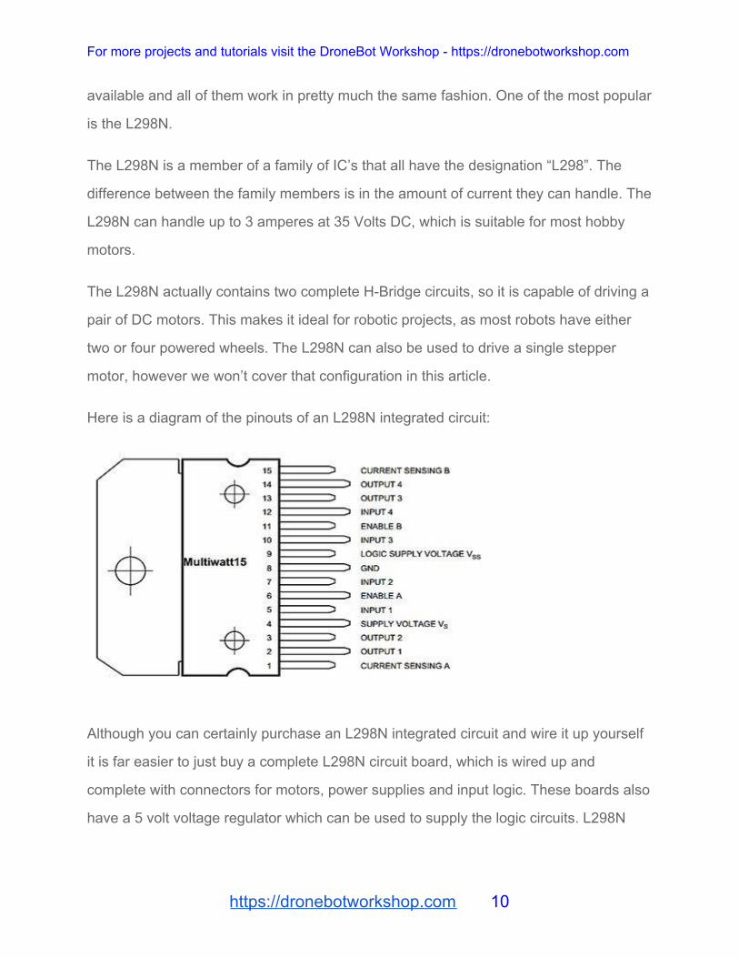
Here is a diagram of the pinouts of an L298N integrated circuit:
Although you can certainly purchase an L298N integrated circuit and wire it up yourself
it is far easier to just buy a complete L298N circuit board, which is wired up and
complete with connectors for motors, power supplies and input logic. These boards also
have a 5 volt voltage regulator which can be used to supply the logic circuits. L298N
https://dronebotworkshop.com 10

For more projects and tutorials visit the DroneBot Workshop - https://dronebotworkshop.com
driver boards are available from a number of sources like eBay or your local electronics
shop at very reasonable prices.
L298N Module Pinouts
You’ll find a few different styles of L298N boards but they all operate in the same
fashion. The board contains an L298N mounted on a heatsink, a 5 volt voltage regulator
to “optionally) provide power for logic circuits, supporting diodes and capacitors and
connectors as follows:
● Logic inputs for each H-Bridge circuit ● Power supply inputs for the motor power supply ● An optional 5 Volt power input for the logic circuits. ● Outputs for each DC motor
A typical L298N Board is shown here.
https://dronebotworkshop.com 11

For more projects and tutorials visit the DroneBot Workshop - https://dronebotworkshop.com
You’ll notice that the board also has a number of jumpers. Most of the time you will
leave them in place, with the exception of one. They are as follows:
● CSA – This is the “current sensing” function for Motor A. If the jumper is in this function is ignored. Most of the time you’ll leave this jumper in place.
● CSB – The “current sensing” function for Motor B. Again you’ll usually just leave this in place to disable this function.
● U1 – Input 1 pull-up resistor. You will usually leave this in place, which enables a 10k pull-up resistor for the input.
● U2 – Input 2 pull-up resistor. ● U3 – Input 3 pull-up resistor. ● U4 – Input 4 pull-up resistor. ● 5v-EN – This is the only jumper that you need to really pay attention to. When
this jumper is in place it enables the boards internal 78M05 5 Volt regulator, supplying logic power from the motor power supply. When this jumper is enabled you will NOT supply 5 volts to the 5 Volt input terminal. When the jumper is removed you will need to supply 5 Volts to the 5 Volt input terminal.
https://dronebotworkshop.com 12
For more projects and tutorials visit the DroneBot Workshop - https://dronebotworkshop.com
If you do use the internal voltage regulator you’ll have to supply the motor power supply
with at least 7.5 volts.
Speaking of the motor power supply it needs to be a bit higher voltage than the actual
motor requirements. This is due to the internal voltage drop in the transistors that form
the H-Bridge circuit. The combined voltage drop is 1.4 volts, so if you are using 6 Volt
motors you’ll need to give the board 7.4 volts, if you have 12 volt motors then your
motor supply voltage will need to be 13.4 volts.
The board has four input terminals plus two enable terminals. You will use these
terminals to control both direction and speed or each motor. They are as follows:
● IN1 – Input 1 for Motor A ● IN2 – Input 2 for Motor A ● IN3 – Input 3 for Motor B ● IN4 – Input 4 for Motor B ● EN1 – Enable line for Motor A ● EN2 – Enable Line for Motor B
In order to simplify things a bit I’ll just discuss the inputs and enable for Motor A, Motor
B functions identically.
The two Input lines control the direction that the motor rotates. I will call one direction
“forward” and the other one “reverse”, if it makes more sense to you just substitute
“clockwise” and “counterclockwise”.
You control motor direction by applying either a Logic 1 (5 Volts) or Logic 0 (Ground) to
the inputs. This chart illustrates how this is done.
https://dronebotworkshop.com 13

For more projects and tutorials visit the DroneBot Workshop - https://dronebotworkshop.com
INPUT 1 INPUT 2 DIRECTION
Ground (0) Ground (0) Motor Off
5 Volts (1) Ground (0) Forward
Ground (0) 5 Volts (1) Reverse
5 Volts (1) 5 Volts (1) Not Used
As you can see only two combinations are actually used to control the direction of the
motors rotation.
The Enable line can be used to turn the motor on, to turn it off and to control its speed.
When the Enable line is at 5 Volts (1) the motor will be on. Grounding the Enable line
(0) will turn the motor off.
To control the speed of the motor you apply a Pulse Width Modulation (PWM) signal to
the Enable line. The shorter the pulse width, the slower the motor will spin.
Breadboard Experiments
We can use a solderless breadboard, a pair of motors and a few jumpers to test the
L298N module.
https://dronebotworkshop.com 14

For more projects and tutorials visit the DroneBot Workshop - https://dronebotworkshop.com
You’ll also need a power supply for the motors. In my experiment I used a second
power supply to supply the 5 Volts for the logic circuitry but you could use one supply
for both motors and logic if you wish. Just be sure to set the 5 Volt Jumper properly (if
you use one supply it should be in place, if you use two like I did remove the jumper).
The initial hookup looks like this:
Note that both the motor and logic power supplies share a common ground. I’ve brought
the 5 Volt supply with ground out to the solderless breadboard so it can be used to set
logic levels.
To get things moving we will need to set the logic levels on the input and enable lines.
In our first experiment we will set EN1, IN1 and IN3 to 5 Volts. The remaining inputs and
enable line will be tied to ground.
https://dronebotworkshop.com 15

For more projects and tutorials visit the DroneBot Workshop - https://dronebotworkshop.com
This arrangement will cause Motor A to move in a forward direction. As the enable line
for Motor B is at ground it will remain off.
Now let’s enable Motor B by setting EN2 to 5 Volts.
https://dronebotworkshop.com 16

For more projects and tutorials visit the DroneBot Workshop - https://dronebotworkshop.com
As you might expect this causes both motors to rotate in a forward direction.
Now we will change the inputs for Motor A, we will set IN1 to ground and IN2 to 5 Volts.
The other connections will remain as they are.
https://dronebotworkshop.com 17

For more projects and tutorials visit the DroneBot Workshop - https://dronebotworkshop.com
If you understood the chart I showed you earlier with the input logic levels you won’t be
surprised to see Motor A now moving in reverse. Motor B continues to move forward.
You can use this arrangement to experiment with controlling the motor direction, as well
as enabling and disabling the two motors. But one thing that you can’t test this way is
controlling motor speed. For this we will need to apply a PWM signal to the Enable
lines. There are a number of ways of accomplishing this, for our next experiment we will
do it using an Arduino.
Using an Arduino with the L298N
Bringing an Arduino or similar microcontroller into the picture allows us to control both
the direction and speed of each motor. I am going to show you how to do this using an
Arduino Uno but you can also accomplish the same thing with a Mega, Nano or other
Arduino compatible controller.
https://dronebotworkshop.com 18

For more projects and tutorials visit the DroneBot Workshop - https://dronebotworkshop.com
The Arduino Uno has 14 digital Input/Output (I/O) pins, six of which are capable of
supplying a PWM signal.
The following diagram shows how I have hooked up the Arduino Uno to the L298N
board.
Note that the 5 Volts for the L298N board is now being supplied from the Arduino 5 Volt
output. The Arduino itself is being powered via its USB cable, which of course will also
allow you to load the sketch to make everything work. After the sketch is loaded you
could remove the USB cable and power the Arduino with an external power supply (or a
USB supply).
The input and enable lines in the L298N are driven from six Arduino digital output pins,
as follows:
https://dronebotworkshop.com 19

For more projects and tutorials visit the DroneBot Workshop - https://dronebotworkshop.com
Arduino L298N
9 EN1
8 IN1
7 IN2
5 IN3
4 IN4
3 EN2
I chose this pinout as Arduino output pins 9 and 3 are both capable of Pulse Width
Modulation, if you wish you can use alternate pins. Just be sure to modify the sketch to
reflect any pinout changes you make.
Speaking of the sketch, here it is:
https://dronebotworkshop.com 20

For more projects and tutorials visit the DroneBot Workshop - https://dronebotworkshop.com
1
2
3
4
5
6
7
8
9
10
11
12
13
14
15
16
17
18
19
20
21
22
23
24
25
26
27
28
29
/*
L298N Motor Demonstration
L298N-Motor-Demo.ino
Demonstrates functions of L298N Motor Controller
DroneBot Workshop 2017
http://dronebotworkshop.com
*/
// Motor A
int enA = 9;
int in1 = 8;
int in2 = 7;
// Motor B
int enB = 3;
int in3 = 5;
int in4 = 4;
void setup()
{
// Set all the motor control pins to outputs
pinMode(enA, OUTPUT);
https://dronebotworkshop.com 21

For more projects and tutorials visit the DroneBot Workshop - https://dronebotworkshop.com
30
31
32
33
34
35
36
37
38
39
40
41
42
43
44
45
46
47
48
49
50
51
52
53
54
55
56
57
58
pinMode(enB, OUTPUT);
pinMode(in1, OUTPUT);
pinMode(in2, OUTPUT);
pinMode(in3, OUTPUT);
pinMode(in4, OUTPUT);
}
void demoOne()
{
// This function will run the motors in both directions at a fixed speed
// Turn on motor A
digitalWrite(in1, HIGH);
digitalWrite(in2, LOW);
// Set speed to 200 out of possible range 0~255
analogWrite(enA, 200);
// Turn on motor B
digitalWrite(in3, HIGH);
digitalWrite(in4, LOW);
// Set speed to 200 out of possible range 0~255
https://dronebotworkshop.com 22

For more projects and tutorials visit the DroneBot Workshop - https://dronebotworkshop.com
59
60
61
62
63
64
65
66
67
68
69
70
71
72
73
74
75
76
77
78
79
80
81
82
83
84
85
86
87
analogWrite(enB, 200);
delay(2000);
// Now change motor directions
digitalWrite(in1, LOW);
digitalWrite(in2, HIGH);
digitalWrite(in3, LOW);
digitalWrite(in4, HIGH);
delay(2000);
// Now turn off motors
digitalWrite(in1, LOW);
digitalWrite(in2, LOW);
digitalWrite(in3, LOW);
digitalWrite(in4, LOW);
}
void demoTwo()
{
// This function will run the motors across the range of possible speeds
// Note that maximum speed is determined by the motor itself and the
operating voltage
https://dronebotworkshop.com 23

For more projects and tutorials visit the DroneBot Workshop - https://dronebotworkshop.com
88
89
90
91
92
93
94
95
96
97
98
99
100
101
102
103
104
105
106
107
108
109
110
111
112
113
114
115
116
// Turn on motors
digitalWrite(in1, LOW);
digitalWrite(in2, HIGH);
digitalWrite(in3, LOW);
digitalWrite(in4, HIGH);
// Accelerate from zero to maximum speed
for (int i = 0; i < 256; i++)
{
analogWrite(enA, i);
analogWrite(enB, i);
delay(20);
}
// Decelerate from maximum speed to zero
for (int i = 255; i >= 0; --i)
{
analogWrite(enA, i);
analogWrite(enB, i);
https://dronebotworkshop.com 24
For more projects and tutorials visit the DroneBot Workshop - https://dronebotworkshop.com
117
118
119
120
121
122
123
124
125
126
127
128
129
130
131
132
133
134
135
136
137
138
139
140
141
142
143
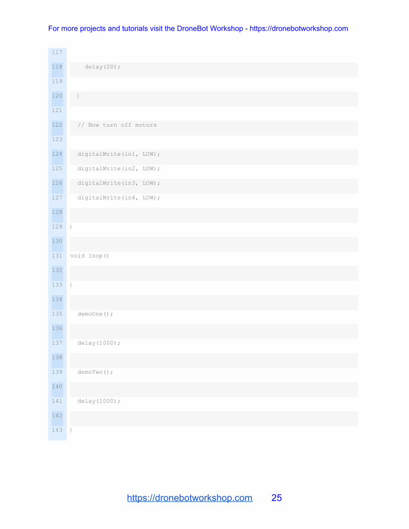
delay(20);
}
// Now turn off motors
digitalWrite(in1, LOW);
digitalWrite(in2, LOW);
digitalWrite(in3, LOW);
digitalWrite(in4, LOW);
}
void loop()
{
demoOne();
delay(1000);
demoTwo();
delay(1000);
}
https://dronebotworkshop.com 25

For more projects and tutorials visit the DroneBot Workshop - https://dronebotworkshop.com
This sketch demonstrates a number of things we can do to control an L298N H-Bridge
with an Arduino. You can play around with it to see what effects changing some values
have and you can also use sections of it as the basis for other motor control sketcheds
you want to create. It could also be used with other H-Bridge controllers as they all
operate in a similar fashion.
We start out by defining integers to represent the digital output pins that will be used to
drive the H-Bridge controller. This is good coding practice as it allows you to change
pin numbers by just changing these values, allowing you to use the same sketch with
different Arduinos. Just remember that the two enable pins, defined as enA and enB,
need to be connected to outputs that support PWM.
In the setup function we define all of these pins as digital outputs.
After that we define two functions. Once you understand how they work feel free to add
more if you wish.
● demoOne – this function spins both motors forward as a speed of 200 for two seconds. It then reverses the motors and spins them for another two seconds. Finally it turns off the motors.
● demoTwo – this function spins the motors forward. First it accelerates them from zero to full speed, then it decelerates them back to zero. Again it turns the motors off when it is done.
In each of these functions Arduino’s analogWrite function is used to produce PWM
signals at the digital outputs. If you plan on working with PWM it’s a very good function
to know.
In the loop we just call the two functions, inserting a one second delay between them.
This continues until you power off the Arduino.
https://dronebotworkshop.com 26

For more projects and tutorials visit the DroneBot Workshop - https://dronebotworkshop.com
Adding Speed Controls
Now that we have the L298N H-Bridge controller working with the Arduino let’s expand
upon it. Our demo sketch really isn’t that practical, especially if we are using our motors
to drive a robot or toy car. What we really need is a way to take control ourselves. So
let’s add some speed controls to our design.
Take a look at the following diagram. Essentially we’ve taken the same circuit and have
added a couple of potentiometers. Each potentiometer has one end tied to ground, the
other end hooked to 5 volts and the wiper connected to an analog input pin ou the
Arduino. The value of the potentiometers isn’t that critical, I used 25k pots as I
happened to have a bunch of them but any value from 10k up would work. Going lower
than 10k wouldn’t be a good idea though as that would start to consume a bit too much
current from the Arduino 5 volt output.
https://dronebotworkshop.com 27

For more projects and tutorials visit the DroneBot Workshop - https://dronebotworkshop.com
The Arduino Uno has 8 analog input pins and again it really doesn’t matter which ones
we use – if you decide to be daring and change pins simply modify the sketch
accordingly. I used the first two – Potentiometer A is connected to analog input A0 while
potentiometer B goes to analog input A1.
Turning the pots will vary the voltage applied to the inputs from zero to 5 volts. In our
sketch we will read these values as numbers from 0 to 1023 (the Arduino Uno has
internal 10 bit analog to digital convertors).
Here is the sketch that I used to take the analog values from the potentiometers and
use them to control the motor speed. Note that in this sketch I haven’t made any
provision to change motor direction.
https://dronebotworkshop.com 28

For more projects and tutorials visit the DroneBot Workshop - https://dronebotworkshop.com
1
2
3
4
5
6
7
8
9
10
11
12
13
14
15
16
17
18
19
20
21
22
23
24
25
26
27
28
29
/*
L298N Motor Control Demonstration with 2 Potentiometers
L298N-Motor-Control-Demo-2pots.ino
Demonstrates use of 2 potentiometers with Arduino and L298N Motor
Controller
DroneBot Workshop 2017
http://dronebotworkshop.com
*/
// Motor A
int enA = 9;
int in1 = 8;
int in2 = 7;
// Motor B
int enB = 3;
int in3 = 5;
int in4 = 4;
// Speed control potentiometers
int SpeedControl1 = A0;
int SpeedControl2 = A1;
// Motor Speed Values - Start at zero
https://dronebotworkshop.com 29
For more projects and tutorials visit the DroneBot Workshop - https://dronebotworkshop.com
30
31
32
33
34
35
36
37
38
39
40
41
42
43
44
45
46
47
48
49
50
51
52
53
54
55
56
57
58
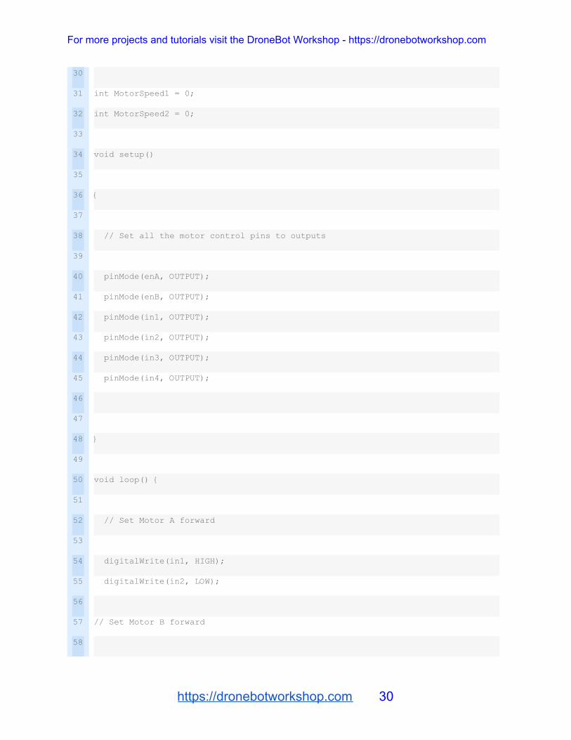
int MotorSpeed1 = 0;
int MotorSpeed2 = 0;
void setup()
{
// Set all the motor control pins to outputs
pinMode(enA, OUTPUT);
pinMode(enB, OUTPUT);
pinMode(in1, OUTPUT);
pinMode(in2, OUTPUT);
pinMode(in3, OUTPUT);
pinMode(in4, OUTPUT);
}
void loop() {
// Set Motor A forward
digitalWrite(in1, HIGH);
digitalWrite(in2, LOW);
// Set Motor B forward
https://dronebotworkshop.com 30

For more projects and tutorials visit the DroneBot Workshop - https://dronebotworkshop.com
59
60
61
62
63
64
65
66
67
68
69
70
71
72
73
74
75
76
77
78
79
80
81
82
83
84
digitalWrite(in3, HIGH);
digitalWrite(in4, LOW);
// Read the values from the potentiometers
MotorSpeed1 = analogRead(SpeedControl1);
MotorSpeed2 = analogRead(SpeedControl2);
// Convert to range of 0-255
MotorSpeed1 = map(MotorSpeed1, 0, 1023, 0, 255);
MotorSpeed2 = map(MotorSpeed2, 0, 1023, 0, 255);
// Adjust to prevent "buzzing" at very low speed
if (MotorSpeed1 < 8)MotorSpeed1 = 0;
if (MotorSpeed2 < 8)MotorSpeed2 = 0;
// Set the motor speeds
analogWrite(enA, MotorSpeed1);
analogWrite(enB, MotorSpeed2);
}
Let’s take a look at this sketch.
https://dronebotworkshop.com 31

For more projects and tutorials visit the DroneBot Workshop - https://dronebotworkshop.com
We begin in a similar fashion to our motor demo sketch, defining integers to represent
output pins to control our H-Bridge. We also define a couple more integers for the
analog inputs that we will use for the potentiometer inputs to A0 and A1. Again you can
rewire to use other inputs and change this section of the sketch accordingly if you wish.
Another set of integers are also defined, MotorSpeed1 and MotorSpeed2. As their name
implies these will hold the values to use to control the motor speeds for each motor. We
initialize these with a value of zero so that our motors start out stationary.
In setup we simply set all the digital pins we defined earlier as outputs. No equivalent
definition for the analog inputs is necessary as by nature these are always inputs.
Now on to the loop. We start by setting the direction of both motors forward which is
done by writing the proper values to the H-Bridge input pins.
Next we read the values of each potentiometer using the analogRead function. As the
Arduino uses an 10-bit A/D convertor this will produce a value ranging from zero to
1023, which is held in each MotorSpeed variable..
We need to convert these MotorSpeed values to a range of 0 – 255 and there are a few
ways we could accomplish this. One method is to divide the values by 4, and this would
work fine (try it an see). But a more eloquent method is to make use of Arduinos map
function which takes a range of values and converts this to a different range of values.
It’s a very handy function that you should get to know if you are not familiar with it.
In experimenting I found that my motors started to “buzz” or “sing” when fed very low
PWM values (you may have noticed this during the demo sketch). To keep from this
annoyance from occurring I popped a couple of if statements into the code to set any
value below 8 to zero. You may need to adjust this value to suit your specific motor/
controller combination.
https://dronebotworkshop.com 32
For more projects and tutorials visit the DroneBot Workshop - https://dronebotworkshop.com
Finally the analogWrite function is used to produce PWM pulses to the enable pins on
the L298N H-Bridge Motor Controller.
This is actually a practical sketch and circuit as it allows us to control each motors
speed independently using the two potentiometers. But it doesn’t allow us to control teh
motor direction. This leads us to our final experiment, one that turns all that we learned
into a practical arrangement for driving a small 2-motor robot car.
Control with a Joystick
Our circuit is now a lot more practical but it still lacks a simple way to change motor
direction. We could use one of the unused digital pins on the Arduino as an input for a
switch to solve this problem, but I thought it might be a bit more fun to use a joystick. If
the two motors are mounted on a small toy car or robot base then the joystick would
provide a fun way to drive our vehicle around the room!
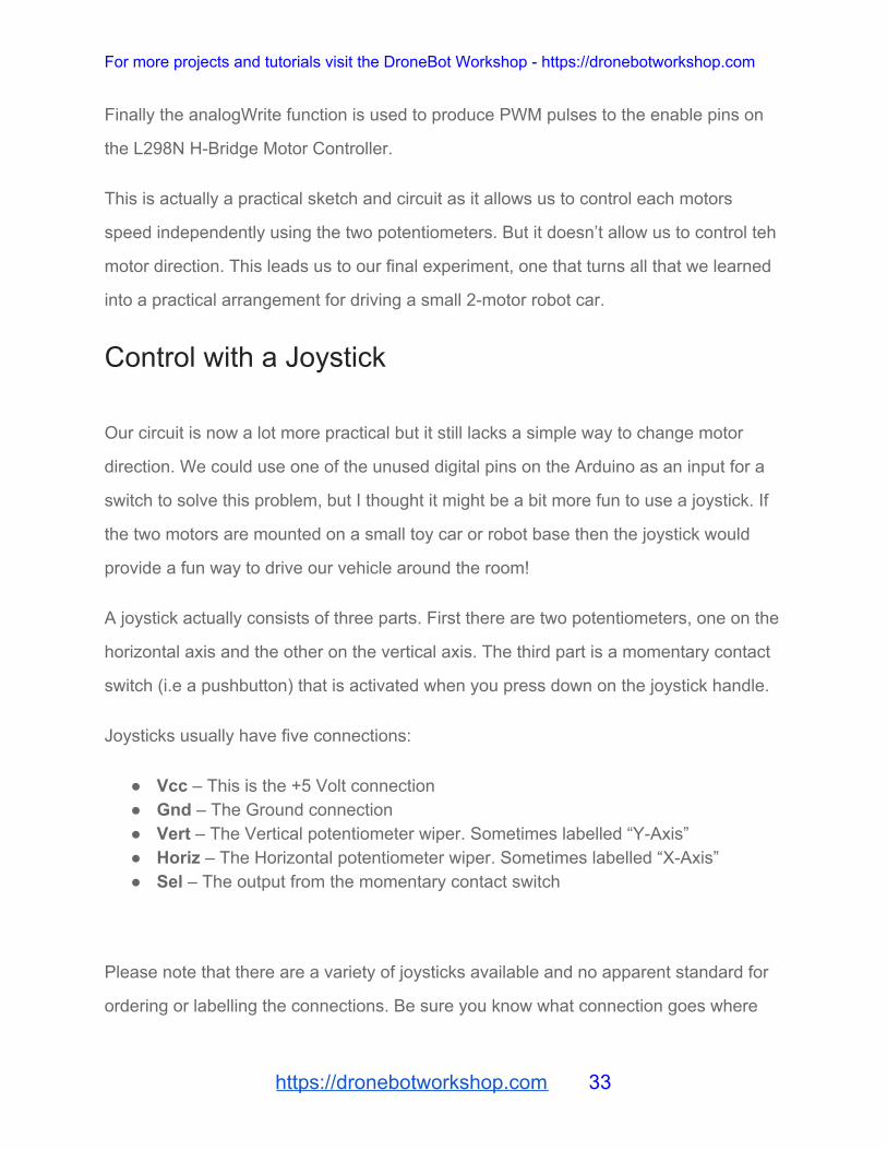
A joystick actually consists of three parts. First there are two potentiometers, one on the
horizontal axis and the other on the vertical axis. The third part is a momentary contact
switch (i.e a pushbutton) that is activated when you press down on the joystick handle.
Joysticks usually have five connections:
● Vcc – This is the +5 Volt connection ● Gnd – The Ground connection ● Vert – The Vertical potentiometer wiper. Sometimes labelled “Y-Axis” ● Horiz – The Horizontal potentiometer wiper. Sometimes labelled “X-Axis” ● Sel – The output from the momentary contact switch
Please note that there are a variety of joysticks available and no apparent standard for
ordering or labelling the connections. Be sure you know what connection goes where
https://dronebotworkshop.com 33

For more projects and tutorials visit the DroneBot Workshop - https://dronebotworkshop.com
before you wire up your joystick. If you’re not sure and can’t find a hookup diagram you
can usually determine the connections using a multimeter.
Once you’ve sorted out your joystick connections you can remove the two
potentiometers we used in the last experiment and hook up the joystick as shown here.
The only real difference between this circuit and the previous one is that the joysticks’
internal potentiometers take the place of the two discrete potentiometers we used
before. I chose not to use the pushbutton switch, if you wish you could tie it to an
unused Arduino input pin and use it to beep a piezo buzzer or flash an LED. I’ll leave
the customizing up to you!
The real fun with this setup lies in the sketch. Before we examine it let’s discuss how
our project will work.
https://dronebotworkshop.com 34

For more projects and tutorials visit the DroneBot Workshop - https://dronebotworkshop.com
● With the joystick resting in its center position the motors will be disabled. In our last experiment the only way to actually stop the motors was to set the speed to zero or unplug the power from the Arduino, not very convenient!
● Pushing the joystick forward (i.e up) should move our car forward. ● Pulling the joystick backward (i.e down) should make the car move backwards. ● As we push the joystick to one side the car should respond by moving in that
direction. We’ll do this by making one motor move faster than the other one. ● Letting the joystick come to rest in the center position should stop the car.
The sketch I came up with to accomplish all this is as follows:
https://dronebotworkshop.com 35

For more projects and tutorials visit the DroneBot Workshop - https://dronebotworkshop.com
1
2
3
4
5
6
7
8
9
10
11
12
13
14
15
16
17
18
19
20
21
22
23
24
25
26
27
28
29
/*
L298N Motor Control Demonstration with Joystick
L298N-Motor-Control-Demo-Joystick.ino
Demonstrates use of Joystick control with Arduino and L298N Motor Controller
DroneBot Workshop 2017
http://dronebotworkshop.com
*/
// Motor A
int enA = 9;
int in1 = 8;
int in2 = 7;
// Motor B
int enB = 3;
int in3 = 5;
int in4 = 4;
// Joystick Input
int joyVert = A0; // Vertical
int joyHorz = A1; // Horizontal
// Motor Speed Values - Start at zero
int MotorSpeed1 = 0;
https://dronebotworkshop.com 36

For more projects and tutorials visit the DroneBot Workshop - https://dronebotworkshop.com
30
31
32
33
34
35
36
37
38
39
40
41
42
43
44
45
46
47
48
49
50
51
52
53
54
55
56
57
58
int MotorSpeed2 = 0;
// Joystick Values - Start at 512 (middle position)
int joyposVert = 512;
int joyposHorz = 512;
void setup()
{
// Set all the motor control pins to outputs
pinMode(enA, OUTPUT);
pinMode(enB, OUTPUT);
pinMode(in1, OUTPUT);
pinMode(in2, OUTPUT);
pinMode(in3, OUTPUT);
pinMode(in4, OUTPUT);
// Start with motors disabled and direction forward
// Motor A
digitalWrite(enA, LOW);
digitalWrite(in1, HIGH);
digitalWrite(in2, LOW);
https://dronebotworkshop.com 37

For more projects and tutorials visit the DroneBot Workshop - https://dronebotworkshop.com
59
60
61
62
63
64
65
66
67
68
69
70
71
72
73
74
75
76
77
78
79
80
81
82
83
84
85
86
87
// Motor B
digitalWrite(enB, LOW);
digitalWrite(in3, HIGH);
digitalWrite(in4, LOW);
}
void loop() {
// Read the Joystick X and Y positions
joyposVert = analogRead(joyVert);
joyposHorz = analogRead(joyHorz);
// Determine if this is a forward or backward motion
// Do this by reading the Verticle Value
// Apply results to MotorSpeed and to Direction
if (joyposVert < 460)
{
// This is Backward
// Set Motor A backward
digitalWrite(in1, LOW);
digitalWrite(in2, HIGH);
// Set Motor B backward
https://dronebotworkshop.com 38

For more projects and tutorials visit the DroneBot Workshop - https://dronebotworkshop.com
88
89
90
91
92
93
94
95
96
97
98
99
100
101
102
103
104
105
106
107
108
109
110
111
112
113
114
115
116
digitalWrite(in3, LOW);
digitalWrite(in4, HIGH);
//Determine Motor Speeds
// As we are going backwards we need to reverse readings
joyposVert = joyposVert - 460; // This produces a negative number
joyposVert = joyposVert * -1; // Make the number positive
MotorSpeed1 = map(joyposVert, 0, 460, 0, 255);
MotorSpeed2 = map(joyposVert, 0, 460, 0, 255);
}
else if (joyposVert > 564)
{
// This is Forward
// Set Motor A forward
digitalWrite(in1, HIGH);
digitalWrite(in2, LOW);
// Set Motor B forward
digitalWrite(in3, HIGH);
digitalWrite(in4, LOW);
https://dronebotworkshop.com 39

For more projects and tutorials visit the DroneBot Workshop - https://dronebotworkshop.com
117
118
119
120
121
122
123
124
125
126
127
128
129
130
131
132
133
134
135
136
137
138
139
140
141
142
143
144
145
//Determine Motor Speeds
MotorSpeed1 = map(joyposVert, 564, 1023, 0, 255);
MotorSpeed2 = map(joyposVert, 564, 1023, 0, 255);
}
else
{
// This is Stopped
MotorSpeed1 = 0;
MotorSpeed2 = 0;
}
// Now do the steering
// The Horizontal position will "weigh" the motor speed
// Values for each motor
if (joyposHorz < 460)
{
// Move Left
// As we are going left we need to reverse readings
joyposHorz = joyposHorz - 460; // This produces a negative number
joyposHorz = joyposHorz * -1; // Make the number positive
// Map the number to a value of 255 maximum
https://dronebotworkshop.com 40

For more projects and tutorials visit the DroneBot Workshop - https://dronebotworkshop.com
146
147
148
149
150
151
152
153
154
155
156
157
158
159
160
161
162
163
164
165
166
167
168
169
170
171
172
173
174
joyposHorz = map(joyposHorz, 0, 460, 0, 255);
MotorSpeed1 = MotorSpeed1 - joyposHorz;
MotorSpeed2 = MotorSpeed2 + joyposHorz;
// Don't exceed range of 0-255 for motor speeds
if (MotorSpeed1 < 0)MotorSpeed1 = 0;
if (MotorSpeed2 > 255)MotorSpeed2 = 255;
}
else if (joyposHorz > 564)
{
// Move Right
// Map the number to a value of 255 maximum
joyposHorz = map(joyposHorz, 564, 1023, 0, 255);
MotorSpeed1 = MotorSpeed1 + joyposHorz;
MotorSpeed2 = MotorSpeed2 - joyposHorz;
// Don't exceed range of 0-255 for motor speeds
if (MotorSpeed1 > 255)MotorSpeed1 = 255;
if (MotorSpeed2 < 0)MotorSpeed2 = 0;
https://dronebotworkshop.com 41

For more projects and tutorials visit the DroneBot Workshop - https://dronebotworkshop.com
175
176
177
178
179
180
181
182
183
184
185
186
187
188
189
}
// Adjust to prevent "buzzing" at very low speed
if (MotorSpeed1 < 8)MotorSpeed1 = 0;
if (MotorSpeed2 < 8)MotorSpeed2 = 0;
// Set the motor speeds
analogWrite(enA, MotorSpeed1);
analogWrite(enB, MotorSpeed2);
}
Let’s examine how the sketch works.
The sketch starts in a similar fashion to the one we used previously,integers are defined
to represent the input pins for the motor input and enable lines. The two analog inputs
are defined as “joyVert” (the joystick vertical or Y axis output) and “joyHorz” (the
horizontal or X axis output). Once again the tow “MotorSpeed” integers represent the
speed of each motor and are initially set to zero.
I’ve also defined two integers to represent the value of each joystick axis position. Each
has a range of 0 to 1023, so the middle position of each is approximately 512 (it’s
actually 511.5, but as we are using integers I selected 512).
https://dronebotworkshop.com 42

For more projects and tutorials visit the DroneBot Workshop - https://dronebotworkshop.com
In the setup function the pins controlling the L298N H-Bridge controller are set as
outputs and the motors are initialized as being disabled and with their directions set
forward.
Now to the loop, where the real action is!
First thing we do is get the position of each joystick potentiometer by reading the value
of the two analog input pins. We will use these values to determine what direction and
speed we want our car to travel in. Keep the following bits of information in mind so that
you understand the logic here:
● The vertical or Y axis control determines if we are going forward or backwards, and how fast. As we push it up we are going forward, pulling it down indicates we want to go backwards. The further to the end we push, the faster we want to go. If we center the joystick then we want the motors to stop.
● The horizontal or X axis control determines if we are moving to the left or right. Keep in mind that to move in one direction you need to spin the opposite motor faster! So, for example, if I want to turn left I need to decrease the speed of the left motor and increase the speed of the right motor. If this control is centered then both motors should revolve at the same speed.
Now that we have these concepts firmly in place let’s see how it’s accomplished in the
sketch.
If our two joystick potentiometers are in the center position then we don’t want to move
either motor. As I mentioned earlier the center positions should produce a value on our
analog inputs of about 512, however in the real world the actual value will be “around
512” as the tolerances in the components isn’t perfect. I chose to allow plus or minus 10
percent, so I consider any value between 460 and 564 to be defined as “center”. You
can experiment with these values if you wish to “fine tune” things to your own joystick.
https://dronebotworkshop.com 43

For more projects and tutorials visit the DroneBot Workshop - https://dronebotworkshop.com
So if the vertical potentiometer is less than 460 then we need to get it’s value and
translate it into a speed, as well as move our motors backwards.
Moving the motors backwards is simply a matter of setting the H-Bridge inputs properly,
as we have done already. Getting the speed however requires a little bit of math, since
we need the speed to increase when the analog input value decreases. No worries, as
it’s fairly basic math – we just subtract 460 from the value of the analog input which
gives us a negative number, then we convert this to a positive number by multiplying by
negative one.
Finally we get the number in our desired range of 0-255 using the handy “map” function
as we did in the previous sketch.
If the vertical potentiometer is reading over 564 then we are going forward. The logic
here is easier as the value goes up while the speed increases, so the “fancy math” isn’t
required. Again we map these values to the range of 0-255.
Now for the steering, which is controlled by the horizontal or X-axis potentiometer.
Remember how this works:
● We’ll be modifying the motor speed values we obtained using the vertical (Y-axis) analog inputs, adding or subtracting from them to make our car turn in the desired direction.
● If the analog input value is less than 460 then we want to go to the left. The lower the value, the more to the left we want to turn
● If the analog input value is over 564 then we want to turn right. In this case the higher the value the more to the right we want to go.
● If the value is between 461 and 563 then we don’t want to turn in either direction. ● Whatever we do the motor speed value cannot drop below zero or exceed 255.
https://dronebotworkshop.com 44

For more projects and tutorials visit the DroneBot Workshop - https://dronebotworkshop.com
With this in mind the code should make sense. Note that this section does not use an
“else” statement like we did for the vertical control, since if the potentiometer is in our
defined center range there is nothing we need to do.
Finally we finish the sketch like we did earlier, adjusting values below 8 to zero so that
the motors don’t “buzz” at extremely low speeds and then finally writing the values out
to the two motor enable lines so that we can control the motor speeds with our L298N
H-Bridge controller.
Summary
We have covered a lot of ground in this article and its accompanying video. We’ve
learned how a DC Motor works, what an H-Bridge is and how we can use the L298N
H-Bridge controller with (and without) and Arduino. We also examined Pulse Width
Modulation, an important concept in motor control as well as a number of other
applications. We even built a crude but functional robot car with a joystick control. Not
bad for a few hours of work!
Other H-Bridge controllers operate in a similar fashion so you can now take your
newfound knowledge and apply it to them as well. So whether you want to control some
tiny motors or a couple of massive ones you are now prepared. Your imagination is the
only limit, so get out your Arduino and make some things move!
https://dronebotworkshop.com 45