controlling normal incident optical waves with an integrated resonator
TRANSCRIPT
Controlling normal incident optical waves with an integrated resonator
Ciyuan Qiu and Qianfan Xu*
Department of Electrical and Computer Engineering, Rice University, Houston, Texas 77005, USA *[email protected]
Abstract: We show a diffraction-based coupling scheme that allows a micro-resonator to directly manipulate a free-space optical beam at normal incidence. We demonstrate a high-Q micro-gear resonator with a 1.57-um radius whose vertical transmission and reflection change 40% over a wavelength range of only 0.3 nm. Without the need to be attached to a waveguide, a dense 2D array of such resonators can be integrated on a chip for spatial light modulation and parallel bio-sensing.
©2011 Optical Society of America
OCIS codes: (130.0130) Integrated optics; (230.5750) Resonators; (050.1950) Diffraction gratings.
References and links
1. Q. Xu, B. Schmidt, S. Pradhan, and M. Lipson, “Micrometre-scale silicon electro-optic modulator,” Nature 435(7040), 325–327 (2005).
2. Q. Xu, S. Manipatruni, B. Schmidt, J. Shakya, and M. Lipson, “12.5 Gbit/s carrier-injection-based silicon micro-ring silicon modulators,” Opt. Express 15(2), 430–436 (2007).
3. P. Dong, R. Shafiiha, S. Liao, H. Liang, N.-N. Feng, D. Feng, G. Li, X. Zheng, A. V. Krishnamoorthy, and M. Asghari, “Wavelength-tunable silicon microring modulator,” Opt. Express 18(11), 10941–10946 (2010).
4. M. S. Rasras, K. Y. Tu, D. M. Gill, Y. K. Chen, A. E. White, S. S. Patel, A. Pomerene, D. Carothers, J. Beattie, M. Beals, J. Michel, and L. C. Kimerling, “Demonstration of a tunable microwave-photonic notch filter using low-loss silicon ring resonators,” J. Lightwave Technol. 27(12), 2105–2110 (2009).
5. H. Shen, M. H. Khan, L. Fan, L. Zhao, Y. Xuan, J. Ouyang, L. T. Varghese, and M. H. Qi, “Eight-channel reconfigurable microring filters with tunable frequency, extinction ratio and bandwidth,” Opt. Express 18(17), 18067–18076 (2010).
6. L. Qing, S. Yegnanarayanan, M. Soltani, P. Alipour, and A. Adibi, “A temperature-iInsensitive third-order coupled-resonator filter for on-chip Terabit/s optical interconnects,” IEEE Photon. Technol. Lett. 22(23), 1768–1770 (2010).
7. Q. Xu, P. Dong, and M. Lipson, “Breaking the delay-bandwidth limit in a photonic structure,” Nat. Phys. 3(6), 406–410 (2007).
8. F. N. Xia, L. Sekaric, and Y. Vlasov, “Ultracompact optical buffers on a silicon chip,” Nat. Photonics 1(1), 65–71 (2007).
9. K. De Vos, I. Bartolozzi, E. Schacht, P. Bienstman, and R. Baets, “Silicon-on-Insulator microring resonator for sensitive and label-free biosensing,” Opt. Express 15(12), 7610–7615 (2007).
10. M. Iqbal, M. A. Gleeson, B. Spaugh, F. Tybor, W. G. Gunn, M. Hochberg, T. Baehr-Jones, R. C. Bailey, and L. C. Gunn, “Label-free biosensor arrays based on silicon ring resonators and high-speed optical scanning instrumentation,” IEEE J. Sel. Top. Quantum Electron. 16(3), 654–661 (2010).
11. K. De Vos, J. Girones, T. Claes, Y. De Koninck, S. Popelka, E. Schacht, R. Baets, and P. Bienstman, “Multiplexed antibody detection with an array of silicon-on-insulator microring resonators,” IEEE Photon. J. 1(4), 225–235 (2009).
12. J. Ahn, M. Fiorentino, R. G. Beausoleil, N. Binkert, A. Davis, D. Fattal, N. P. Jouppi, M. McLaren, C. M. Santori, R. S. Schreiber, S. M. Spillane, D. Vantrease, and Q. Xu, “Devices and architectures for photonic chip-scale integration,” Appl. Phys., A Mater. Sci. Process. 95(4), 989–997 (2009).
13. A. Shacham, K. Bergman, and L. P. Carloni, “Photonic networks-on-chip for future generations of chip multiprocessors,” IEEE Trans. Comput. 57(9), 1246–1260 (2008).
14. A. V. Krishnamoorthy, R. Ho, X. Zheng, H. Schwetman, J. Lexau, P. Koka, G. Li, I. Shubin, and J. E. Cunningham, “Computer systems based on silicon photonic interconnects,” Proc. IEEE 97(7), 1337–1361 (2009).
15. M. H. Khan, H. Shen, Y. Xuan, L. Zhao, S. J. Xiao, D. E. Leaird, A. M. Weiner, and M. H. Qi, “Ultrabroad-bandwidth arbitrary radiofrequency waveform generation with a silicon photonic chip-based spectral shaper,” Nat. Photonics 4(2), 117–122 (2010).
16. N. Savage, “Digital spatial light modulators,” Nat. Photonics 3(3), 170–172 (2009). 17. D. Taillaert, P. Bienstman, and R. Baets, “Compact efficient broadband grating coupler for silicon-on-insulator
waveguides,” Opt. Lett. 29(23), 2749–2751 (2004).
#155840 - $15.00 USD Received 3 Oct 2011; revised 7 Dec 2011; accepted 9 Dec 2011; published 16 Dec 2011(C) 2011 OSA 19 December 2011 / Vol. 19, No. 27 / OPTICS EXPRESS 26905

18. A. Yariv, “Coupled-mode theory for guided-wave optics,” IEEE J. Quantum Electron. 9(9), 919–933 (1973). 19. M. Fujita and T. Baba, “Proposal and finite-difference time-domain simulation of whispering gallery mode
microgear cavity,” IEEE J. Quantum Electron. 37(10), 1253–1258 (2001). 20. B. Redding, S. Y. Shi, T. Creazzo, E. Marchena, and D. W. Prather, “Design and characterization of silicon
nanocrystal microgear resonators,” Photonics Nanostruct. Fundam. Appl. 8(3), 177–182 (2010).
1. Introduction
Integrated optical resonators are widely used to manipulate light propagation in a waveguide that is evanescently coupled to the resonator. Based on the silicon micro-ring resonators, various photonic devices including electro-optic modulators [1–3], filters [4–6], optical buffers [7, 8] and bio-sensors [9–11] have been demonstrated. They have compact sizes, low power consumption and are compatible with standard microelectronics, enabling large-scale integration of optoelectronic system on-chip for such applications as optical interconnection [12–14] and optical signal processing [4, 15]. Light are well confined in these resonators because its wave vector does not match that of any free-space wave. Thus, these resonators can only interact with the outside world through the evanescently coupled waveguide, which prevents them to be used as spatial light modulators for such applications as image processing, beam steering, parallel optical logic, parallel signal processing, 3D optical interconnections.
Here we show a novel diffraction-based coupling scheme, which allows a micro-resonator to directly manipulate a free-space optical beam at normal incidence. We experimentally demonstrate a high-Q micro-gear resonator with a 1.57-um radius whose vertical transmission and reflection change 40% over a wavelength range of only 0.3 nm. The micro-gear resonator we show here is essentially an dielectric optical antenna that directly converts freely propagating waves to intensive and localized resonating field and vice versa. Without the need for side-coupled waveguides, this type of resonator can easily be made into dense 2D arrays. Ultrafast spatial light modulator with a wide range of applications [16] can be built by controlling the free-carrier density in this resonator [1]. When micro-gear resonators are functionalized as bio-sensors, a dense 2D array acts as a highly-sensitized surface that can be directly examined under a conventional microscopic system. In comparison, probing such a dense array with waveguides requires a waveguide network that is impractically bulky and lossy. The micro-gear resonators can also be lifted off from the substrate to be used as colloidal particles or to be deposited on other substrates where ultra-compact and high-Q resonators are not otherwise available. While our demonstration is based on silicon resonators working at near-infrared, the underline physical principle can be directly applied to resonators made of other dielectric materials and resonators working in other wavelength ranges.
2. Theory of diffractive coupling
To see how the diffraction-based coupling scheme works, let us first look at a waveguide grating coupler [17], which can be described as a variation in the distribution of dielectric
constant ( )rε∆�
compared to that of a smooth waveguide. Figure 1(a) shows the top view of a
grating that couples a transverse-electric (TE) waveguide mode ( )E r�
�
with a vertical beam
(travelling in ±z directions). Using the coupled-mode theory [18] we can explain this coupling
effect based on the perturbation polarization induced by the grating ( ) ( ) ( )pertP r r E rε= ∆� �
� � �
,
which acts as the source for secondary waves. If the period of the grating matches the spatial
period of the waveguide mode, as shown in Fig. 1(a), pertP�
at both the wider ( ( ) 0rε∆ >�
) and
narrower ( ( ) 0rε∆ <�
) sections of the waveguide point in the same direction. They interfere
constructively and create a strong radiation in the vertical direction. When this waveguide grating is curved around to form a micro-ring resonator, however, it no longer couples to
vertical waves because pertP�
now point to different directions Fig. 1(b) shows a micro-ring
resonator with a 14-period grating matching the periodicity of the 14th longitudinal
#155840 - $15.00 USD Received 3 Oct 2011; revised 7 Dec 2011; accepted 9 Dec 2011; published 16 Dec 2011(C) 2011 OSA 19 December 2011 / Vol. 19, No. 27 / OPTICS EXPRESS 26906

(azimuthal) mode of the resonator. pertP�
at opposite sides of the ring point in opposite
directions and thus destructive interfere in the vertical direction. To analyze the coupling to the vertical wave in this situation, one needs to look at the
Cartesian field components Ex and Ey, instead of the radial component Er plotted in Fig. 1(b). The gratings need to match the periodicity of Ex in order to couple to a x-polarized wave, and match the periodicity of Ey in order to couple to a y-polarized wave. Figure 1(c) shows the simulated Ex distribution of the 14th longitudinal mode, which has 13 periods around the inner circumference of the ring and 15 periods around the outer circumference. That is because Ex becomes the longitudinal field component with an odd parity at the ± y sections of the ring, and the longitude field component has about the same amplitude as the transverse field component at the edge of this highly-confined waveguide. Thus, to create strong coupling to an x-polarized vertical wave, one needs a 13-period grating around the inner circumference and/or a 15-period grating around the outer circumference to match the Ex field distribution.
Fig. 1. Top-view diagrams to illustrate the principle of operation of the micro-gear resonators. The white arrows show the directions of the perturbation polarization. (a) The transverse field of a TE mode of a silicon strip waveguide and the perturbation polarization induced by a grating shown by the black lines. (b) The transverse (radial) electric field component Er of the 14th longitudinal (azimuthal) mode of a micro-ring resonator and the perturbation polarization induced by a 14-period grating. (c) Simulated Ex distribution when a micro-gear resonator is excited by a x-polarized normal-incidence Gaussian beam with a beam radius of 1.75um and a peak amplitude of 1. The gratings are illustrated by the black lines in the figure, where their widths are exaggerated for better visibility. The inner grating has 13 periods and the outer grating has 15 periods. (d) Simulated Ey distribution when the micro-gear resonator in (c) is illuminated by a y-polarized Gaussian beam with the same size and amplitude as that in (c).
The device shown in Fig. 1(c) has both a 100-nm-wide inner grating and a 10-nm-wide outer grating. Excluding the gratings, the inner radius of the ring is 0.91um, the outer radius of the ring is 1.57um, and the height of the ring is 0.25um. These are the default dimensions used throughout this paper except where it is noted. Since the convex parts of the grating
( ( ) 0rε∆ >�
) overlap with positive Ex field, and the concave parts of the grating ( ( ) 0rε∆ <�
)
overlap with negative Ex field, the perturbation polarization pertP�
always point to the
positive-x direction, as shown by the white arrows. The gratings, therefore, strongly couple the x-polarized vertical wave with the resonant field, which creates an intense resonant field whose intensity (|E|
2) is ~2,000 times higher than that of the input beam. Because the shape of
#155840 - $15.00 USD Received 3 Oct 2011; revised 7 Dec 2011; accepted 9 Dec 2011; published 16 Dec 2011(C) 2011 OSA 19 December 2011 / Vol. 19, No. 27 / OPTICS EXPRESS 26907

the resonator resembles a gear, it is named a micro-gear resonator. This device is, however, fundamentally different from the micro-gear resonators demonstrated previously where a 2m-period grating is used to enhance the quality factor Q of the m-th longitudinal mode of a micro-disk resonator [19, 20].
The micro-gear resonator shown above does not strongly interact with a y-polarized normal-incidence beam. One can see from Fig. 1(d) that, because the inner and outer gratings
have opposite phase at ±y sections of the resonator, the y-component of pertP�
induced by the
inner grating points to the opposite direction as that induced by the outer grating. If the effective strengths of the two gratings (which depend on the width of the grating and the amplitude of the local field) are the same, a y-polarized vertical wave will not couple to the
resonating field because the two pertP�
components destructively interfere with each other. If
coupling only to the y-polarized beam is desired, one can simply invert the phase of either the inner grating or the outer grating. To achieve a polarization-independent coupling, on the other hand, one can use solely the inner grating or solely the outer grating.
3. Experimental demonstrations
Micro-gear resonators with gratings of different sizes are fabricated on the silicon-on-insulator (SOI) substrate with e-beam lithography. The SOI substrate has a 250-nm-thick silicon layer on a 3-µm-thick buried oxide layer. Figure 2(a) shows an SEM picture of a waveguide-coupled micro-gear resonator with the default dimensions. While the outer grating is too narrow to be indentified on the SEM picture, its optical effects are clearly seen in the experiments below. Figure 2(b) shows a stand-alone micro-gear resonator whose gratings are wide enough to be seen clearly. Though the micro-gears are intended to be used as stand-alone resonators, the waveguide-coupled ones are used here to characterize their basic properties.
Fig. 2. The scanning electron microscopic (SEM) pictures of the fabricated micro-gear resonators. (a) The SEM picture of a waveguide-coupled micro-gear resonator with a 100-nm-wide inner grating and a 10-nm-wide outer grating. (b) The SEM picture of a stand-alone micro-gear resonator with a 400-nm-wide inner grating and an 80-nm-wide outer grating.
The measurements on the waveguide-coupled micro-gear resonators confirm that the gratings significantly enhance vertical radiation from the resonator. The black line in Fig. 3(a) is the normalized waveguide transmission spectrum of the device shown in Fig. 2(a), and the red line shows its vertical radiation which is collected into a single-mode optical fiber by a lens and a fiber collimator. The top radiation spectrum shows a clear peak for the 14
th
longitudinal mode around the wavelength of 1536 nm. This is the mode that the gratings are designed for. In comparison, the vertical radiation from the 13
th longitudinal mode at the
wavelength of 1610 nm is ~16 times lower in power. The radiation pattern at 1610 nm has a dark center as shown in the right inset of Fig. 3(a), due to the destructive interference in the vertical direction. Without the gratings, the vertical radiation from a micro-ring resonator is ~30 times lower than that from the micro-gear resonator, as shown in Fig. 3(c).
The radiation around 1536 nm is confirmed to be largely x-polarized from the zoom-in spectra of the x-polarized (red line) and y-polarized radiations (purple line) in Fig. 3(b). The
high contrast (~16 dB) between the two polarization components show that pertP�
induced by
#155840 - $15.00 USD Received 3 Oct 2011; revised 7 Dec 2011; accepted 9 Dec 2011; published 16 Dec 2011(C) 2011 OSA 19 December 2011 / Vol. 19, No. 27 / OPTICS EXPRESS 26908
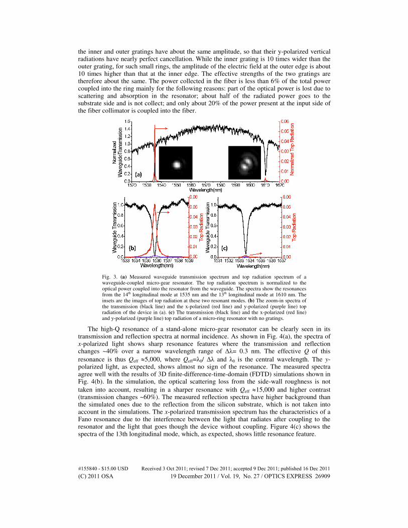
the inner and outer gratings have about the same amplitude, so that their y-polarized vertical radiations have nearly perfect cancellation. While the inner grating is 10 times wider than the outer grating, for such small rings, the amplitude of the electric field at the outer edge is about 10 times higher than that at the inner edge. The effective strengths of the two gratings are therefore about the same. The power collected in the fiber is less than 6% of the total power coupled into the ring mainly for the following reasons: part of the optical power is lost due to scattering and absorption in the resonator; about half of the radiated power goes to the substrate side and is not collect; and only about 20% of the power present at the input side of the fiber collimator is coupled into the fiber.
Fig. 3. (a) Measured waveguide transmission spectrum and top radiation spectrum of a waveguide-coupled micro-gear resonator. The top radiation spectrum is normalized to the optical power coupled into the resonator from the waveguide. The spectra show the resonances from the 14th longitudinal mode at 1535 nm and the 13th longitudinal mode at 1610 nm. The insets are the images of top radiation at these two resonant modes. (b) The zoom-in spectra of the transmission (black line) and the x-polarized (red line) and y-polarized (purple line) top radiation of the device in (a). (c) The transmission (black line) and the x-polarized (red line) and y-polarized (purple line) top radiation of a micro-ring resonator with no gratings.
The high-Q resonance of a stand-alone micro-gear resonator can be clearly seen in its transmission and reflection spectra at normal incidence. As shown in Fig. 4(a), the spectra of x-polarized light shows sharp resonance features where the transmission and reflection changes ~40% over a narrow wavelength range of ∆λ= 0.3 nm. The effective Q of this
resonance is thus Qeff ≈5,000, where Qeff=λ0/ ∆λ and λ0 is the central wavelength. The y-polarized light, as expected, shows almost no sign of the resonance. The measured spectra agree well with the results of 3D finite-difference-time-domain (FDTD) simulations shown in Fig. 4(b). In the simulation, the optical scattering loss from the side-wall roughness is not
taken into account, resulting in a sharper resonance with Qeff ≈15,000 and higher contrast (transmission changes ~60%). The measured reflection spectra have higher background than the simulated ones due to the reflection from the silicon substrate, which is not taken into account in the simulations. The x-polarized transmission spectrum has the characteristics of a Fano resonance due to the interference between the light that radiates after coupling to the resonator and the light that goes though the device without coupling. Figure 4(c) shows the spectra of the 13th longitudinal mode, which, as expected, shows little resonance feature.
#155840 - $15.00 USD Received 3 Oct 2011; revised 7 Dec 2011; accepted 9 Dec 2011; published 16 Dec 2011(C) 2011 OSA 19 December 2011 / Vol. 19, No. 27 / OPTICS EXPRESS 26909

We measured the normal incident transmission spectra of micro-gear resonators with gratings of different sizes, which are shown in Fig. 4(d). When the widths of the gratings increase, one can see consistently the increase of the extinction ratio and the drop of Qeff as the rate of the grating-induced vertical radiation increases. The micro-ring resonator with no gratings (the green line) shows no feature from its resonance (in fact, we cannot precisely locate the resonant wavelength because of that), which confirms that the grating structures are necessary for coupling to normal incident beams.
Fig. 4. Normal-incidence transmission and reflection spectra of stand-alone micro-gear resonators. (a) The red and brown lines are measured x-polarized and y-polarized transmission spectra. The blue and black lines are measured x-polarized and y-polarized reflection spectra. (b) The spectra with the same definitions as those in (a) obtained from a 3D FDTD simulation. (c) The measured transmission (red) and reflection (blue) spectra around the 13th longitudinal mode of the resonator. (d) Normalized x-polarized transmission spectra of stand-alone resonators with gratings of different sizes. Each spectrum is normalized to its off-resonance transmission. Green line: micro-ring with no grating. Black line: micro-gear with a 50-nm inner grating and a 5-nm outer grating. Red line: micro-gear with the default dimensions. Blue line: micro-gear with a 200-nm inner grating and a 20-nm outer grating.
While the demonstrated 40% extinction ratio is high enough to precisely identify the resonant wavelength for bio-sensing applications, it can be further improved by reducing the losses in the ring, reducing the non-resonant scattering of the vertical beam, and reducing higher-order diffractions from the gratings. The desired vertical radiation is the 0
th-order
diffraction of the grating, and the higher-order diffractions act as addition losses that prevent critical coupling. For a grating with diameter D, the m
th-order diffraction centers at an angle
satisfying D·sinθ = m·λ/nc, where λ is the wavelength and nc is the refractive index of the cladding material. When the diameter of the grating becomes less than λ/nc, only the 0
th-order
diffraction exists, therefore critical coupling can be achieved. Simulations show that improved designs can have more than 16 dB extinction ratio with less than 0.7 dB insertion loss, making high-quality spatial modulation possible.
4. Conclusion
We develop a new diffraction-based coupling scheme that allows a micro-resonator to directly manipulate a free-space optical beam at normal incidence. While the device we show here is near-IR resonator built on silicon, the same principle applies to resonators built on other high-index-contrast material systems and resonators working in other wavelength regions.
#155840 - $15.00 USD Received 3 Oct 2011; revised 7 Dec 2011; accepted 9 Dec 2011; published 16 Dec 2011(C) 2011 OSA 19 December 2011 / Vol. 19, No. 27 / OPTICS EXPRESS 26910