controlwave lp quick setup guide (d5121) - emerson lp controlwave lp quick setup guide . ... this...
TRANSCRIPT

www.EmersonProcess.com/Bristol
Quick Setup Guide D5121 December, 2006
ControlWave LP
ControlWave LP Quick Setup Guide

THIS PAGE INTENTIONALLY LEFT BLANK
IMPORTANT! READ INSTRUCTIONS BEFORE STARTING! Be sure that these instructions are carefully read and understood before any operation is attempted. Improper use of this device in some applications may result in damage or injury. The user is urged to keep this book filed in a convenient location for future reference. These instructions may not cover all details or variations in equipment or cover every possible situation to be met in connection with installation, operation or maintenance. Should problems arise that are not covered sufficiently in the text, the purchaser is advised to contact Bristol, Inc. for further information.
EQUIPMENT APPLICATION WARNING The customer should note that a failure of this instrument or system, for whatever reason, may leave an operating process without protection. Depending upon the application, this could result in possible damage to property or injury to persons. It is suggested that the purchaser review the need for additional backup equipment or provide alternate means of protection such as alarm devices, output limiting, fail-safe valves, relief valves, emergency shutoffs, emergency switches, etc. If additional information is required, the purchaser is advised to contact Bristol, Inc..
RETURNED EQUIPMENT WARNING When returning any equipment to Bristol, Inc. for repairs or evaluation, please note the following: The party sending such materials is responsible to ensure that the materials returned to Bristol, Inc. are clean to safe levels, as such levels are defined and/or determined by applicable federal, state and/or local law regulations or codes. Such party agrees to indemnify Bristol, Inc. and save Bristol, Inc. harmless from any liability or damage which Bristol, Inc. may incur or suffer due to such party's failure to so act.
ELECTRICAL GROUNDING Metal enclosures and exposed metal parts of electrical instruments must be grounded in accordance with OSHA rules and regulations pertaining to "Design Safety Standards for Electrical Systems," 29 CFR, Part 1910, Subpart S, dated: April 16, 1981 (OSHA rulings are in agreement with the National Electrical Code). The grounding requirement is also applicable to mechanical or pneumatic instruments that include electrically-operated devices such as lights, switches, relays, alarms, or chart drives.
Thank you for choosing ControlWave LP!
4
We hope you will find ControlWave LP to be the best solution for your process automation needs. From the start, Bristol designed this unit to merge the simplicity and modularity of a programmable logic controller, with the full communication and programming capabilities of a remote process controller. The result - the ControlWave Low Powered (LP) Controller, is a true PLC/RTU hybrid, incorporating the best features of both types of devices. ControlWave LP features a low-power, modular design, which supports all five IEC 61131-3 programming languages: ladder logic (LD), sequential flow chart (SFC), function block diagram (FBD), structured text (ST), and instruction list (IL). A full suite of PC-based configuration wizards and programming tools is provided.
Before You Begin This guide is intended to help you get ‘up-and-running’ with a minimal amount of effort. It does NOT, however, tell you everything you need to know about setting up and configuring a ControlWave LP. We have included references throughout this book to other places in the documentation set, where you can get more details on a particular subject. Throughout your configuration activities, please be aware of the following items: Shock Hazard! Always follow accepted safety guidelines. As with all electronic devices, improper installation, grounding, or usage can cause an electrical shock. If you have any doubts about how to install, ground, and use this product safely, please consult a qualified electrician. Electrostatic Discharge (ESD) - Sensitive electronic devices such as this can be damaged by electrostatic discharge. Please follow accepted ESD guidelines.
If You Need Help… If you're having problems setting up and configuring your ControlWave LP, please call our ControlWave Application Support team at (860) 945-2394 or (860) 945-2286 for assistance. Help is available Monday through Friday 8:00 AM to 4:30 PM Eastern Time, excluding holidays, and scheduled factory shutdowns.

Table of Contents
5
Part 1 Setting Up the Hardware................................................................................................................. 8 Installing ControlWave Designer Software on the PC ................................................................. 12 Creating a Simple Project in Ladder Language (LD) ................................................................... 14 Part 2 Establishing Comunications with LocalView / NetView ............................................................. 29 Using the Flash Configuration Utility........................................................................................... 32 Setting Soft Switches .................................................................................................................... 37 Configuring Communication Ports ............................................................................................... 38
Setting Up A BSAP Slave Port .............................................................................................. 38 Setting Up an Ethernet Port.................................................................................................... 40 Recommended Ranges for IP Addresses ............................................................................... 41 Other Port Types: ................................................................................................................... 42
Configuring IP Parameters............................................................................................................ 43 Configuring User Accounts and Privileges................................................................................... 45
Adding A New User............................................................................................................... 45 Modifying the Privileges of an Existing User........................................................................ 48 Deleting An Existing User ..................................................................................................... 48 When You Have Finished Making Security Changes............................................................ 48
What's Next? ................................................................................................................................. 49 Appendix A - Troubleshooting Tips ........................................................................................... A-1

6
7
Part 1 This part of the manual discusses the initial steps necessary to set up an all NEW ControlWave LP, and start to use it.
• Setting up the Hardware This section gives you a quick overview of how to set the switches, and where to connect the cable between the ControlWave LP and the PC. References are included to the hardware manual for details of the individual steps.
• Installing ControlWave Designer on the PC This section provides instructions for installing ControlWave Designer software on your PC. ControlWave Designer is the software which allows you to create an application-specific program (called a project) that will execute inside the ControlWave LP.
• Creating a Simple Project in Ladder Language (LD) This section shows how to create a very simple program in ladder language (LD) which is one of the five IEC 61131-3 languages supported by ControlWave. In addition, this section also discusses how to compile the program, and download it into the ControlWave LP.
Setting up the Hardware
8
Hardware Configuration
Setting Up the Hardware
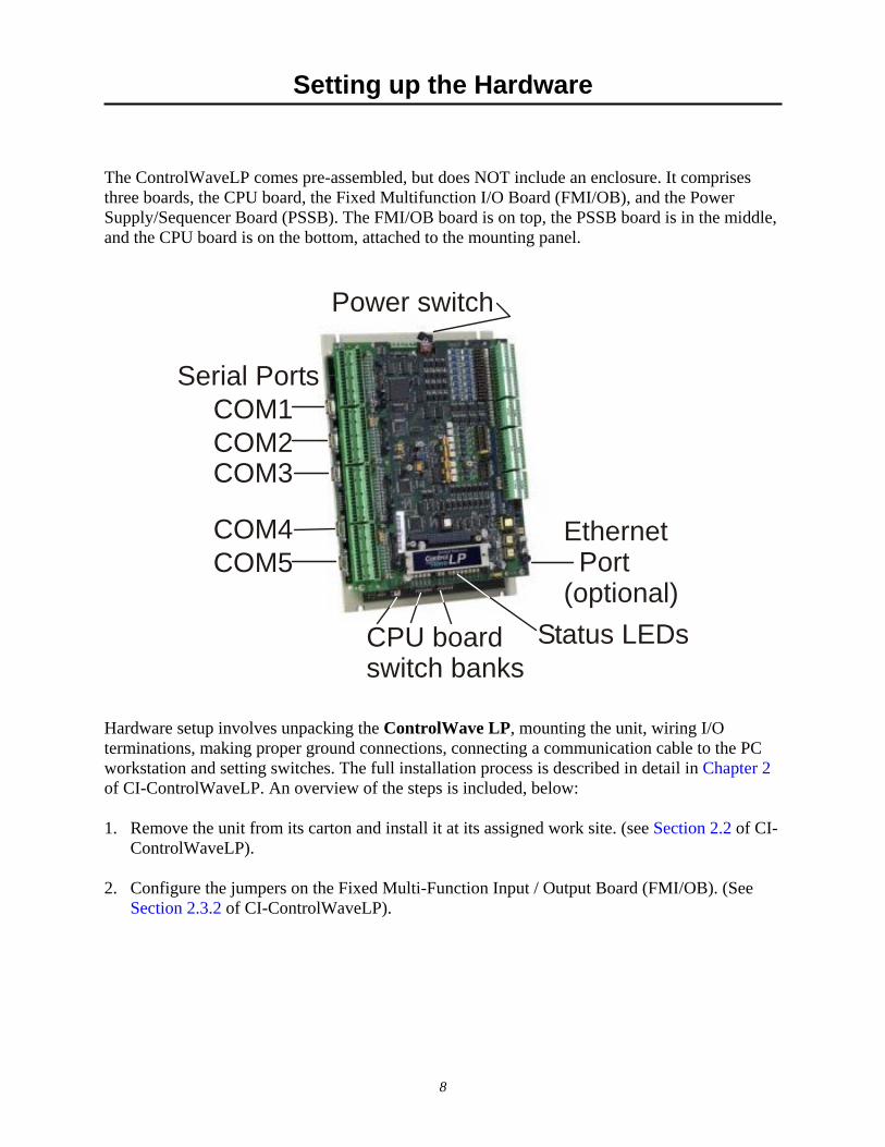
The ControlWaveLP comes pre-assembled, but does NOT include an enclosure. It comprises three boards, the CPU board, the Fixed Multifunction I/O Board (FMI/OB), and the Power Supply/Sequencer Board (PSSB). The FMI/OB board is on top, the PSSB board is in the middle, and the CPU board is on the bottom, attached to the mounting panel.
Hardware setup involves unpacking the ControlWave LP, mounting the unit, wiring I/O terminations, making proper ground connections, connecting a communication cable to the PC workstation and setting switches. The full installation process is described in detail in Chapter 2 of CI-ControlWaveLP. An overview of the steps is included, below: 1. Remove the unit from its carton and install it at its assigned work site. (see Section 2.2 of CI-
ControlWaveLP). 2. Configure the jumpers on the Fixed Multi-Function Input / Output Board (FMI/OB). (See
Section 2.3.2 of CI-ControlWaveLP).
Serial PortsCOM1COM2COM3
COM4COM5
Ethernet Port (optional)
CPU boardswitch banks
Power switch
Status LEDs
Setting up the Hardware
9
SW2 SW4 SW5 - UNUSED - IGNORE
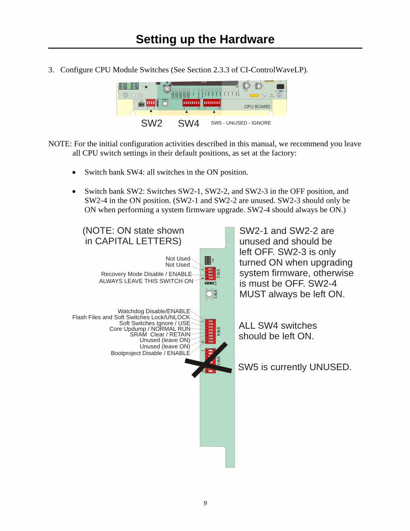
3. Configure CPU Module Switches (See Section 2.3.3 of CI-ControlWaveLP). NOTE: For the initial configuration activities described in this manual, we recommend you leave
all CPU switch settings in their default positions, as set at the factory:
• Switch bank SW4: all switches in the ON position.
• Switch bank SW2: Switches SW2-1, SW2-2, and SW2-3 in the OFF position, and SW2-4 in the ON position. (SW2-1 and SW2-2 are unused. SW2-3 should only be ON when performing a system firmware upgrade. SW2-4 should always be ON.)
ALWAYS LEAVE THIS SWITCH ON
Not UsedRecovery Mode Disable / ENABLE
Not Used
(NOTE: ON state shown in CAPITAL LETTERS)
SW2-1 and SW2-2 areunused and should beleft OFF. SW2-3 is onlyturned ON when upgradingsystem firmware, otherwiseis must be OFF. SW2-4 MUST always be left ON.
SW5 is currently UNUSED.
ALL SW4 switchesshould be left ON.
Watchdog Disable/ENABLEFlash Files and Soft Switches Lock/UNLOCK
Soft Switches Ignore / USECore Updump / NORMAL RUN
SRAM Clear / RETAIN
Unused (leave ON)Unused (leave ON)
Bootproject Disable / ENABLE

Setting up the Hardware
10
4. For the configuration activities, described in this manual, we will use Serial Communication
Port 2 (COM2) on the ControlWave LP, which is configured by default for 9600 baud. (For more information on communication ports see Section 2.3.4 of CI-ControlWaveLP).
• Plug one end of an RS-232 null modem cable1 into one of your PC communication ports. • Plug the other end of the RS-232 null modem cable into Serial Communication Port 2
(COM2) of the ControlWave LP.
5. Install I/O wiring to each I/O Module (see Section 2.4.1 through 2.4.4 of CI-
ControlWaveLP). 6. Install Watchdog Relay/MOSFET Switch wiring (see Section 2.4.5 of CI-ControlWaveLP).
(OPTIONAL - perform this step only if you want to use this feature.)
1 For a wiring diagram of an RS-232 null modem cable, see Figure 2-5 in the CI-ControlWaveLP manual.
Plug RS232 Null ModemCable into COM Port 2
Setting up the Hardware
11
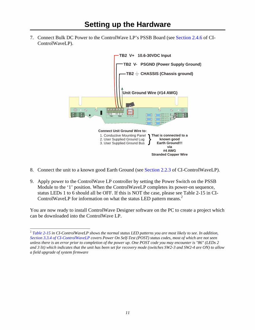
Unit Ground Wire (#14 AWG)
1. Conductive Mounting Panel2. User Supplied Ground Lug3. User Supplied Ground Bus
Connect Unit Ground Wire to:That is connected to a
known goodEarth Ground!!!
via#4 AWG
Stranded Copper Wire
TB2 CHASSIS (Chassis ground)
TB2 V- PSGND (Power Supply Ground)
TB2 V+ 10.6-30VDC Input
7. Connect Bulk DC Power to the ControlWave LP’s PSSB Board (see Section 2.4.6 of CI-ControlWaveLP).
8. Connect the unit to a known good Earth Ground (see Section 2.2.3 of CI-ControlWaveLP). 9. Apply power to the ControlWave LP controller by setting the Power Switch on the PSSB
Module to the ‘1’ position. When the ControlWaveLP completes its power-on sequence, status LEDs 1 to 6 should all be OFF. If this is NOT the case, please see Table 2-15 in CI-ControlWaveLP for information on what the status LED pattern means.2
You are now ready to install ControlWave Designer software on the PC to create a project which can be downloaded into the ControlWave LP.
2 Table 2-15 in CI-ControlWaveLP shows the normal status LED patterns you are most likely to see. In addition, Section 3.3.4 of CI-ControlWaveLP covers Power On Self-Test (POST) status codes, most of which are not seen unless there is an error prior to completion of the power up. One POST code you may encounter is "86" (LEDs 2 and 3 lit) which indicates that the unit has been set for recovery mode (switches SW2-3 and SW2-4 are ON) to allow a field upgrade of system firmware

Installing ControlWave Designer Software on the PC
12
nstalling ControlWave LP Designer Software on the PC
For more detailed explanations of software installation options, see Chapter 2 of the Open BSI Utilities Manual (document# D5081).
Recommended Requirements for the Open BSI Workstation: 133 MHz Pentium® CPU (Pentium 4 or higher CPU recommended) PC workstation with: • at least 85 MB free disk space • 32 MB RAM (more recommended) • CD ROM drive • VGA Monitor (minimum 256 colors 800x600). Optimal screen resolution when using Bristol
web pages is 1024 x 768. • Mouse • Microsoft® Windows™ 2000 (Service Pack 3 or newer required) or XP Professional. We
recommend you install the latest available service pack for your operating system. NOTE: Open BSI/ControlWave Designer is currently tested on the following platforms only: Pentium 4 with Windows™ XP Professional, Windows™ 2000, and Windows™ 2003 Server. Open BSI/ControlWave Designer software has NOT been tested on dual core processors or hyper-threaded processors.
• Microsoft® Internet Explorer Version 5 or newer (Required for configuration web pages used by ControlWave users).
• Microsoft® Access and ODBC - Windows™ 2000 version or newer • RS-232 null modem cable (required to connect the PC to the ControlWave LP)
Before You Begin the Software Installation ControlWave Designer software is installed from within Windows™. We recommend that all other Windows™ application programs you have running should be shut down before beginning installation.
IMPORTANT If you are installing under Windows™ NT, you must be logged on with administrative privileges.
IMPORTANT - Remove Older Versions Prior to Installation Before installing this kit on a computer which already has Open BSI 3.22 (or earlier versions) you MUST first remove the previous version(s) of Open BSI. To remove the older kits or components, use the Add/Remove programs option from the Windows™ Control Panel. When files have been removed, use Windows™ Explorer to browse the Open BSI installation directory (usually \OPENBSI) and manually delete any remaining .EXE, .DLL, or .OCX files.

Installing ControlWave Designer Software on the PC
13
Installing the ControlWave Designer Software 1. Insert the Open BSI CD-ROM in your CD ROM drive. 2. If your CD-ROM drive has autorun enabled, skip to the next step. Otherwise, use
Windows™ Explorer to locate the file BROWSER.EXE in the root directory of the CD. Double-click on BROWSER.EXE. When the CD browser screen appears, choose the “Install OpenBSI’’ option.
3. A screen reminding you to close all other programs, and warning you that older Open
BSI versions will be removed, will appear. Click on [Next>]. 4. A license agreement screen will appear. Review the agreement, using the scroll bar to
bring it into view. Click on “I accept the terms of the license agreement” in order to proceed. Then click on [Next>].
A list of available software packages will be displayed similar to the one shown, at right. Choose “ControlWave Designer with ACCOL III” as well as any other packages you want to install then click on [Next>].
5. Now, you can specify, if desired, different directories for storage of data and
configuration files. Otherwise, leave the directories at their default settings. 6. Now, click on [Next>]. This is your last opportunity to make any changes prior to
starting the installation. If you want to make changes, you can use the [<Back] button to go back to earlier pages. If you are ready to perform the installation, click on the [Install>] button, and the installation process will begin. Be patient, as it may take several minutes to install all of the different utilities, depending upon which you have chosen. When the installation has completed, you will be prompted to re-boot your computer, which must be done in order for the software to run properly. If you don’t choose to do it now, you should do it before starting ControlWave Designer.
7. Click on [Finish], and the installation will be complete, and re-boot will proceed, if you
chose to do it now. Once installation is complete, an ‘OpenBSI Tools’ menu selection will be added to your Windows Start Programs menu through which you can access ControlWave Designer. At this point, you can begin the initial configuration activities for your new ControlWave LP.

Creating a Simple Project in Ladder Language (LD)
14
Creating a Simple Project in Ladder Language (LD)
Now, let's create a VERY simple project to run in your ControlWave LP. Let's say we have a water tank - when the water level in the tank goes below a certain level, a WATER_LOW signal is turned ON, and as a result, a START_PUMP signal needs to be turned ON to refill the tank. Similarly, we want to issue a START_PUMP signal any time the drain valve for the tank is open. Our project is so simple, we aren't going to handle turning off the pump, or what happens if the tank overflows; we just want to show how either of two conditions cause the pump to be started. NOTE: We won't be defining the I/O for this project; we're keeping it as simple as possible.
Step 1. Start ControlWave Designer: • Click on Start Programs OpenBSI Tools ControlWave Designer IMPORTANT: If this is the very first time ControlWave Designer has been started on this particular computer, you will be reminded to register the software. Otherwise, the software can only be used for a maximum of 30 days. For more information on the registration process, see Chapter 2 of the Open BSI Utilities Manual (document# D5081).
Step 2. Open a new project: • Click on File New Project • Double-click on the ControlWave icon. • The left-window pane of ControlWave
Designer will be filled with a structure called the project tree.

Creating a Simple Project in Ladder Language (LD)
15
Step 3. Insert a new logical program organization unit (POU). • Right click on "Logical POUs" in the
project tree, and choose "Insert" and “Program” from the pop-up menus.
Step 4. Name the POU, and specify it as a program in ladder language (LD). • Enter the name ‘SIMPLE’. • Choose "Program" as the
type. (If not already chosen.) • Choose "LD" as the language. • Click on [OK].
Creating a Simple Project in Ladder Language (LD)
16
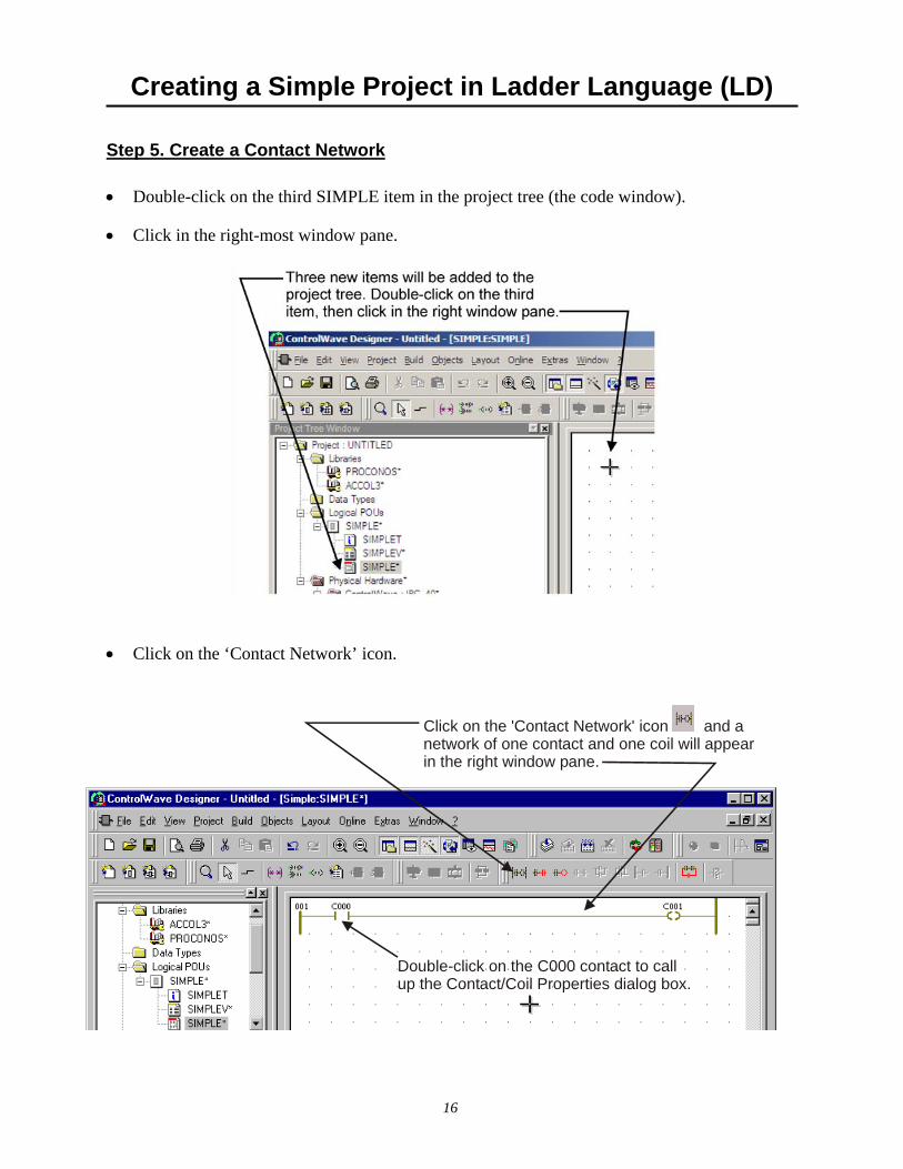
Click on the 'Contact Network' icon and anetwork of one contact and one coil will appearin the right window pane.
Double-click on the C000 contact to callup the Contact/Coil Properties dialog box.
Step 5. Create a Contact Network • Double-click on the third SIMPLE item in the project tree (the code window). • Click in the right-most window pane.
• Click on the ‘Contact Network’ icon.

Creating a Simple Project in Ladder Language (LD)
17
Step 6. Define the ‘WATER_LOW’ variable. • Double-click on the ‘C000’
contact to call up the Contact/Coil Properties dialog box. (See illustration, on previous page)
• Enter the variable name
‘WATER_LOW’ in place of ‘C000’ in the "Name" field, then click on [OK].
Enter a variable name 'WATER_LOW' then click on [OK]

Creating a Simple Project in Ladder Language (LD)
18
Now, click on the 'Add contact/coil below' icon...
... and the parallel branch will be added below
Double-click on the C002 contact to call upthe Contact/Coil Properties dialog box.
Step 7. Insert a contact/coil below, and define the ‘DRAIN_OPEN’ variable: • Click on the ‘Add contact/coil
below’ icon. • Another contact called ‘C002’
will be added below the ‘WATER_LOW’ contact, defined earlier.
• Double-click on the new contact
‘C002’, to call up the Contact/ Coil Properties dialog box.
• Enter ‘DRAIN_OPEN’ in
place of ‘C002’ in the "Name" field of the Contact /Coil Properties dialog box, and click on [OK].
Enter 'DRAIN_OPEN' as the variable name,then click on [OK]
Creating a Simple Project in Ladder Language (LD)
19
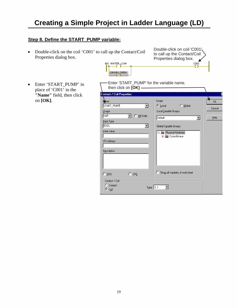
Double-click on coil 'C001'to call up the Contact/CoilProperties dialog box.
Step 8. Define the START_PUMP variable: • Double-click on the coil ‘C001’ to call up the Contact/Coil
Properties dialog box. • Enter ‘START_PUMP’ in
place of ‘C001’ in the "Name" field, then click on [OK].
Enter 'START_PUMP' for the variable name,then click on [OK]

Creating a Simple Project in Ladder Language (LD)
20
Step 9. Create a task, and associate the program with that task: • Right-click on ‘Tasks’ under the
RTU_RESOURCE in the project tree, then choose "Insert" and “Task” from the menu. The Insert dialog box will appear.
• Choose "Task" as the
‘Type’. • Choose ‘CYCLIC’ as
the "Task Type". • Enter ‘T1’ in the
"Name" field. (You could name it something else, this is just the name we have chosen for this example.)
• Click on [OK].
Choose as the 'Type'"Task"
Enter 'T1' as the name of the taskFinally, click on [OK]
Choose 'CYCLIC' for the 'Task Type'
• Choose the default settings
shown in the Task Settings dialog box by clicking on [OK].
Use the default task settings, and click on [OK]

Creating a Simple Project in Ladder Language (LD)
21
• Right-click on the ‘T1’ folder which is now
in the project tree, and choose "Insert" and “Program Instance” from the pop-up menu. The Insert dialog box will appear.
• Choose "Program" for the
‘Type’. • Enter ‘P1’ as the "Program
instance" name. • Click on [OK].
Enter 'P1' as the 'Program Instance' nameChoose for the 'Type'
"Program Instance"Finally, click on [OK]

Creating a Simple Project in Ladder Language (LD)
22
Step 10. Compile the program: • Compile the program by clicking on the ‘Make’ icon. You should see a message saying there
were ‘0 Errors’ in the ‘Build’ window at the bottom left of the screen. Disregard any warnings you see at this time.

Creating a Simple Project in Ladder Language (LD)
23
Step 11. Download the project into the ControlWave LP:
• Right-click on the RTU_RESOURCE in
the project tree, and choose “Settings” from the menu. The Resource Settings dialog box will appear.
WARNING Users should never attempt to download an untested program into a controller if the controller is currently connected to a running plant or industrial process. Safeguards must be taken prior to downloading to ensure that the controller is isolated from the process and I/O is disconnected. Failure to take such precautions could result in injury to persons or damage to property.
Creating a Simple Project in Ladder Language (LD)
24
Click on the 'Project Control Dialog' icon
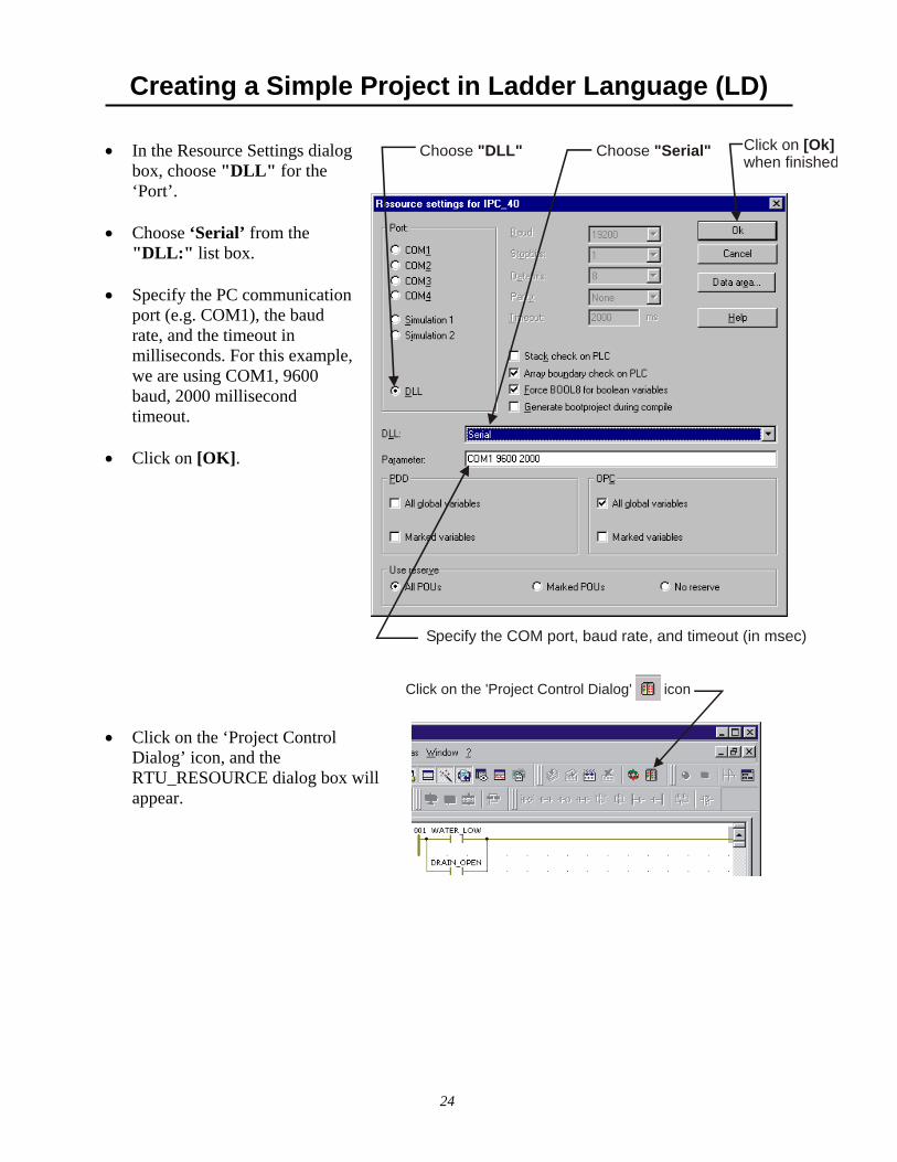
• In the Resource Settings dialog box, choose "DLL" for the ‘Port’.
• Choose ‘Serial’ from the
"DLL:" list box. • Specify the PC communication
port (e.g. COM1), the baud rate, and the timeout in milliseconds. For this example, we are using COM1, 9600 baud, 2000 millisecond timeout.
• Click on [OK].
Choose "DLL" Choose "Serial"
Specify the COM port, baud rate, and timeout (in msec)
Click on when finished
[Ok]
• Click on the ‘Project Control
Dialog’ icon, and the RTU_RESOURCE dialog box will appear.
Creating a Simple Project in Ladder Language (LD)
25
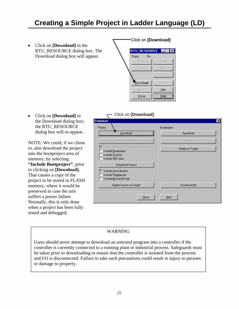
• Click on [Download] in the
RTU_RESOURCE dialog box. The Download dialog box will appear.
• Click on [Download] in
the Download dialog box; the RTU_RESOURCE dialog box will re-appear.
NOTE: We could, if we chose to, also download the project into the bootproject area of memory, by selecting “Include Bootproject”, prior to clicking on [Download]. That causes a copy of the project to be stored in FLASH memory, where it would be preserved in case the unit suffers a power failure. Normally, this is only done when a project has been fully tested and debugged.
Click on [Download]
WARNING Users should never attempt to download an untested program into a controller if the controller is currently connected to a running plant or industrial process. Safeguards must be taken prior to downloading to ensure that the controller is isolated from the process and I/O is disconnected. Failure to take such precautions could result in injury to persons or damage to property.

Creating a Simple Project in Ladder Language (LD)
26
Enter Debug Mode by clicking on the 'Debug On/Off' icon
• Sign-on to the ControlWave LP by
entering the username "SYSTEM" and the password "666666" in response to the Login prompt, then click on [OK]. The download will now proceed. (NOTE: SYSTEM is a default security account which is included in the ControlWave LP when it ships from the factory, so that you can access the ControlWave LP during initial configuration, before any other user accounts have been defined.)
• At this point, status LED 6 on the ControlWave LP should be
lit (code 1), indicating that a project has been downloaded, but is NOT running yet. Click on [Cold] to start the newly downloaded project. LED 6 should go out, indicating that the project is now running.
Step 12 - Test the logic of the program in Debug Mode • Enter Debug Mode by
clicking on the ‘Debug On/Off’ icon.
• If it isn't visible, expand
the SIMPLE folder (under Logical POUs in the project tree) and double-click on the third ‘SIMPLE’ worksheet.
• If desired, you can minimize the RTU_RESOURCE dialog box if it's in your way.

Creating a Simple Project in Ladder Language (LD)
27
To force the value to true click on thenclick on the button
TRUE, [Overwrite]
• Currently, both contacts and the coil should have a value of 0 (FALSE). You can see the value by moving the cursor over the coil / contact. Also, FALSE items are highlighted in BLUE and TRUE items are highlighted in RED.
• Double-click on either one of the contacts (in this case we chose the WATER_LOW
contact). The Debug RTU_Resource dialog box will appear. • Click on "TRUE" for the
‘Value’ • Click on [Overwrite]. • The START_PUMP coil should have
automatically turned TRUE (VALUE of 1) based on the WATER_LOW contact being set to ‘1’ (TRUE). You can verify this by moving the cursor over the START_PUMP coil.
(Another way to verify the change is to look and see that both these items appear highlighted in RED.) Congratulations! You've just created and downloaded your first ControlWave project! (If you have encountered problems, and weren't able to get this far, try to re-trace your steps, and see if you missed something. If, after reviewing the steps, you are still encountering problems, call our ControlWave Application Support Team for help at one of the numbers listed on page 4.)

28
Part 2 Now that you've created a project, and downloaded it successfully, it's time to learn more about configuring the ControlWave LP. The configuration in this part is performed using the Flash Configuration Utility. • Establishing Communications with LocalView / NetView
If the ControlWave LP has already been installed in an Open BSI network, and configured in NetView, starting NetView is the easiest way to establish communications. If the ControlWave LP has not been included in a network yet, LocalView is the preferred method of communication.
• Using the Flash Configuration Utility
The Flash Configuration Utility may be started from within either LocalView or NetView. Once running, all major configuration settings for the ControlWave LP can be set. The most commonly used settings are discussed in the remaining sections.
• Setting Soft Switches
This section discusses how to configure the local address, and EBSAP group number, and other parameters that are important if you will be including the ControlWave LP as part of a larger Bristol network.
• Configuring Communication Ports
This section discusses how to configure the serial ports, and, optionally, the Ethernet port, on the ControlWave LP.
• Configuring IP Parameters
This section discusses how to specify the IP address of the Network Host PC (NHP), as well as common IP network security parameters.
• Configuring User Accounts and Privileges
This section discusses how to define usernames and passwords, and set appropriate access privileges for each person, who will use the ControlWave LP.

Establishing Communication with LocalView / NetView
29
Choose the communication port on (NOT on the ControlWave LP)
the PCworkstation
Specify the baud rate for that port
Finally, click on [Next>]
Establishing Comunications with LocalView / NetView
Establishing Communications Using LocalView Step 1. Click as follows: Start Programs OpenBSI Tools LocalView Step 2. Choose ‘Local’ for the mode, enter a name for the LocalView file, and click on [Create].
First, choose'Local' as the mode.
Next, enter aname for this LocalViewfile.
Finally, clickon [Create]
Step 3. Choose the communication port on the PC workstation which you will use to
communicate with the ControlWave LP. Then, specify the baud rate for that port, and click on the [Next>] button.

Establishing Communication with LocalView / NetView
30
Turn off auto local address detectionUse "1" as the local addressChoose
'CWave_LP'
Finally, click on [Finish]
Right-click on the RTU icon
Step 4. First, turn off auto local address detection by answering "No" to the question. Then specify ‘1’ as the local address, and ‘CWave_LP’ as the RTU type. Finally, click on [Finish].
Step 5. At this point, LocalView will create a temporary network with a single ControlWave LP
controller called, generically, ‘RTU’. Right-click on the icon, then choose RTU RTU Configuration Parameters from the pop-up menus.
Step 6. The Flash Configuration Utility will appear. See 'Using the Flash Configuration Utility’,
later in this manual.

Establishing Communication with LocalView / NetView
31
Establishing Communications Using NetView (ControlWave LP Already In a Network) IMPORTANT: This method assumes that the ControlWave LP has already been included in an
Open BSI network within the NetView program, and that it has been configured to communicate over that network's communication line as described in the Open BSI Utilities Manual (document# D5081).
Step 1. Click as follows: Start Programs OpenBSI Tools NetView Step 2. Right-click on the ControlWave LP icon, in the NetView network tree, and choose
RTU RTU Configuration Parameters from the pop-up menus.
Step 3. The Flash Configuration Utility will appear. See 'Using the Flash Configuration Utility’,
later in this manual.
Right-click on the RTU icon
Using the Flash Configuration Utility
32
Using the Flash Configuration Utility
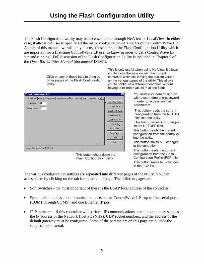
The Flash Configuration Utility may be accessed either through NetView or LocalView. In either case, it allows the user to specify all the major configuration parameters of the ControlWave LP. As part of this manual, we will only discuss those parts of the Flash Configuration Utility which are important for a first-time ControlWave LP user to know in order to get a ControlWave LP ‘up and running’. Full discussion of the Flash Configuration Utility is included in Chapter 5 of the Open BSI Utilities Manual (document# D5081).
The various configuration settings are separated into different pages of the utility. You can access them by clicking on the tab for a particular page. The different pages are: • Soft Switches - the most important of these is the BSAP local address of the controller. • Ports - this includes all communication ports on the ControlWave LP - up to five serial ports
(COM1 through COM5), and one Ethernet IP port. • IP Parameters - if this controller will perform IP communications, certain parameters such as
the IP address of the Network Host PC (NHP), UDP socket numbers, and the address of the default gateway must be configured. Some of the parameters on this page are outside the scope of this manual.

Using the Flash Configuration Utility
33
• Application Parameters - Most of these are ‘tuning’ parameters which govern how the ControlWave LP executes its application (project). A discussion of application parameters is outside the scope of this manual.
• Archive - Archive data is one portion of the historical capabilities of the ControlWave LP
controller. It allows ‘snapshots’ of many variables to be saved at the same instant, to provide a detailed historical record of process variables at a particular moment in time. The archive data is saved at the controller, in structures called archive files and is configured, in part, using the ARCHIVE function block in your ControlWave project. Archive files may be collected by Open BSI Utilities such as DataView, or the Harvester. A discussion of archive configuration is outside the scope of this manual.
• Audit – Audit data is one portion of the historical capabilities of the ControlWave LP
controller. It allows records to be kept of when certain variables change value, as well as recording all alarms in the system. The Audit page specifies various parameters used to set up the Audit system. Configuration is also performed, in part, using the AUDIT function block in your ControlWave project. A discussion of audit configuration is outside the scope of this manual.
• IP Routes - Dynamic IP routes allow messages which cannot successfully reach a particular
destination address, to be re-routed through a different path in the IP network. A discussion of this subject is outside the scope of this manual.
• Security - This page allows configuration of user accounts and privileges. Push Buttons: [Apply New Node] This button is only useful when the Flash Configuration utility is started
from within NetView (since no other nodes are accessible in the Select New Node dialog box within LocalView). It allows the session with the current controller to be closed, and then allows the user to select a different controller (node) for configuration, without reinitializing the values in the pages of the utility. The new controller must have been defined within the NETDEF files.
Using the Flash Configuration Utility
34
One application of this is to open a session with a new controller, and then load configuration information from the NETDEF file(s) that was for a different controller (via [Load from File]). This can be useful if multiple controllers have similar configurations; the common configuration can be brought into the utility, and then the unique portions only need to be modified for each individual controller.
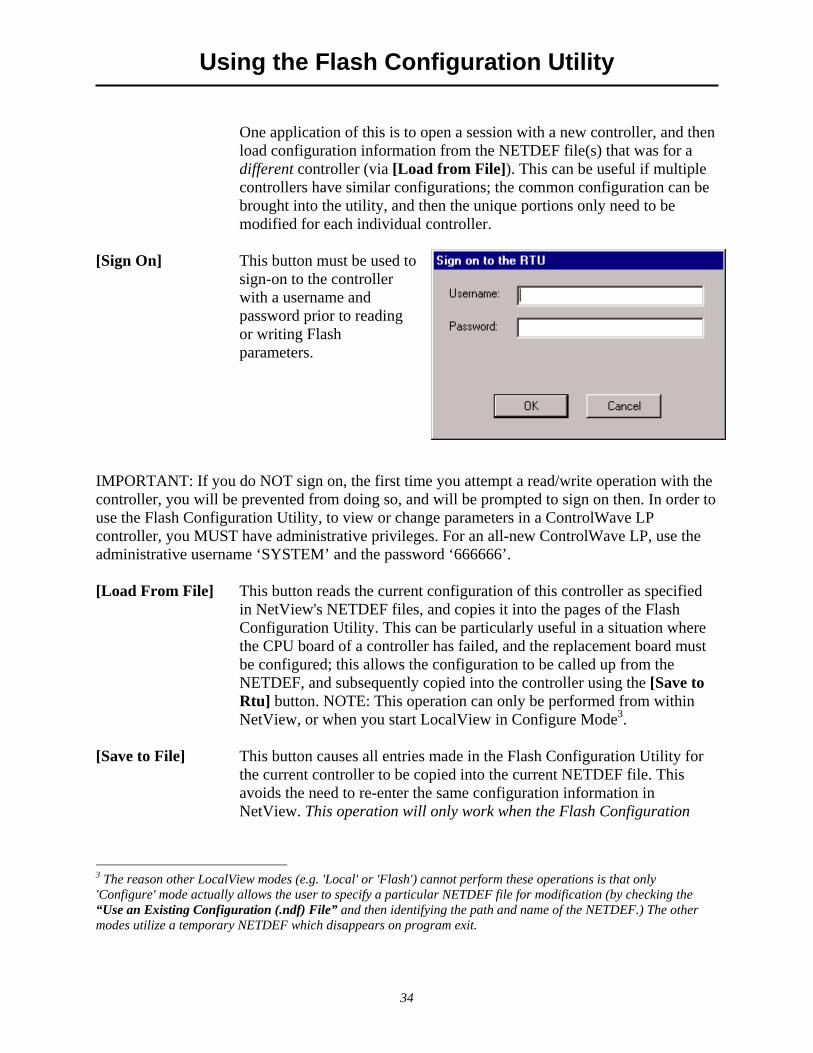
[Sign On] This button must be used to
sign-on to the controller with a username and password prior to reading or writing Flash parameters.
IMPORTANT: If you do NOT sign on, the first time you attempt a read/write operation with the controller, you will be prevented from doing so, and will be prompted to sign on then. In order to use the Flash Configuration Utility, to view or change parameters in a ControlWave LP controller, you MUST have administrative privileges. For an all-new ControlWave LP, use the administrative username ‘SYSTEM’ and the password ‘666666’. [Load From File] This button reads the current configuration of this controller as specified
in NetView's NETDEF files, and copies it into the pages of the Flash Configuration Utility. This can be particularly useful in a situation where the CPU board of a controller has failed, and the replacement board must be configured; this allows the configuration to be called up from the NETDEF, and subsequently copied into the controller using the [Save to Rtu] button. NOTE: This operation can only be performed from within NetView, or when you start LocalView in Configure Mode3.
[Save to File] This button causes all entries made in the Flash Configuration Utility for
the current controller to be copied into the current NETDEF file. This avoids the need to re-enter the same configuration information in NetView. This operation will only work when the Flash Configuration
3 The reason other LocalView modes (e.g. 'Local' or 'Flash') cannot perform these operations is that only 'Configure' mode actually allows the user to specify a particular NETDEF file for modification (by checking the “Use an Existing Configuration (.ndf) File” and then identifying the path and name of the NETDEF.) The other modes utilize a temporary NETDEF which disappears on program exit.
Using the Flash Configuration Utility
35
Utility is invoked from within NetView or when LocalView is in Configure Mode; otherwise a permanent NETDEF file is not available to write to4.
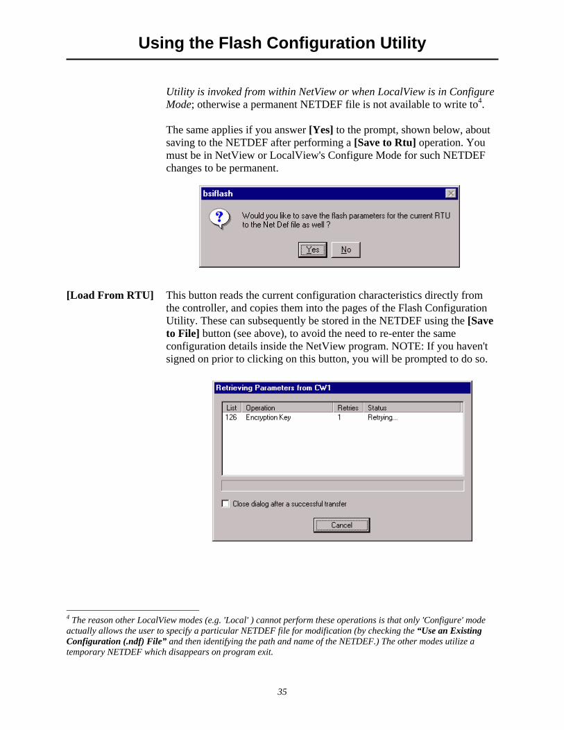
The same applies if you answer [Yes] to the prompt, shown below, about saving to the NETDEF after performing a [Save to Rtu] operation. You must be in NetView or LocalView's Configure Mode for such NETDEF changes to be permanent.
[Load From RTU] This button reads the current configuration characteristics directly from
the controller, and copies them into the pages of the Flash Configuration Utility. These can subsequently be stored in the NETDEF using the [Save to File] button (see above), to avoid the need to re-enter the same configuration details inside the NetView program. NOTE: If you haven't signed on prior to clicking on this button, you will be prompted to do so.
4 The reason other LocalView modes (e.g. 'Local' ) cannot perform these operations is that only 'Configure' mode actually allows the user to specify a particular NETDEF file for modification (by checking the “Use an Existing Configuration (.ndf) File” and then identifying the path and name of the NETDEF.) The other modes utilize a temporary NETDEF which disappears on program exit.
Using the Flash Configuration Utility
36
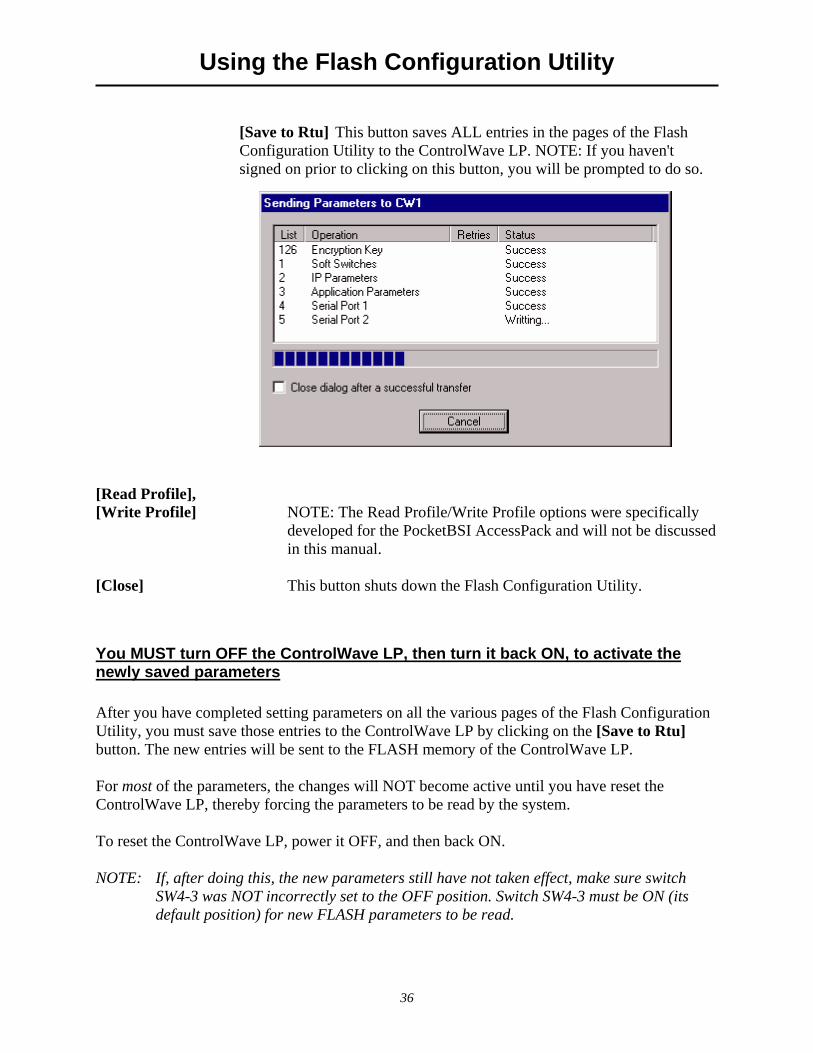
[Save to Rtu] This button saves ALL entries in the pages of the Flash Configuration Utility to the ControlWave LP. NOTE: If you haven't signed on prior to clicking on this button, you will be prompted to do so.
[Read Profile], [Write Profile] NOTE: The Read Profile/Write Profile options were specifically
developed for the PocketBSI AccessPack and will not be discussed in this manual.
[Close] This button shuts down the Flash Configuration Utility.
You MUST turn OFF the ControlWave LP, then turn it back ON, to activate the newly saved parameters After you have completed setting parameters on all the various pages of the Flash Configuration Utility, you must save those entries to the ControlWave LP by clicking on the [Save to Rtu] button. The new entries will be sent to the FLASH memory of the ControlWave LP. For most of the parameters, the changes will NOT become active until you have reset the ControlWave LP, thereby forcing the parameters to be read by the system. To reset the ControlWave LP, power it OFF, and then back ON. NOTE: If, after doing this, the new parameters still have not taken effect, make sure switch
SW4-3 was NOT incorrectly set to the OFF position. Switch SW4-3 must be ON (its default position) for new FLASH parameters to be read.
Setting Soft Switches (incl. Local Address)
37
Setting Soft Switches
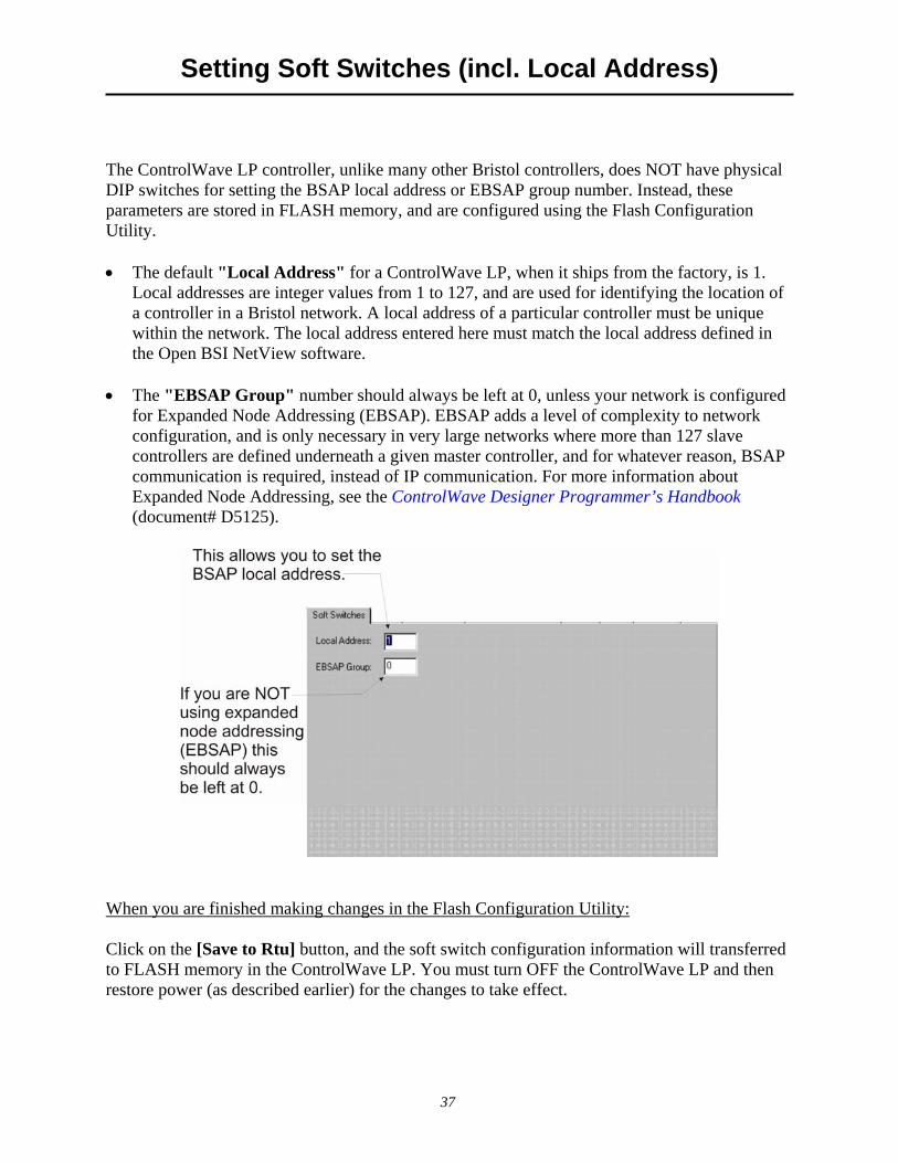
The ControlWave LP controller, unlike many other Bristol controllers, does NOT have physical DIP switches for setting the BSAP local address or EBSAP group number. Instead, these parameters are stored in FLASH memory, and are configured using the Flash Configuration Utility. • The default "Local Address" for a ControlWave LP, when it ships from the factory, is 1.
Local addresses are integer values from 1 to 127, and are used for identifying the location of a controller in a Bristol network. A local address of a particular controller must be unique within the network. The local address entered here must match the local address defined in the Open BSI NetView software.
• The "EBSAP Group" number should always be left at 0, unless your network is configured
for Expanded Node Addressing (EBSAP). EBSAP adds a level of complexity to network configuration, and is only necessary in very large networks where more than 127 slave controllers are defined underneath a given master controller, and for whatever reason, BSAP communication is required, instead of IP communication. For more information about Expanded Node Addressing, see the ControlWave Designer Programmer’s Handbook (document# D5125).
When you are finished making changes in the Flash Configuration Utility: Click on the [Save to Rtu] button, and the soft switch configuration information will transferred to FLASH memory in the ControlWave LP. You must turn OFF the ControlWave LP and then restore power (as described earlier) for the changes to take effect.

Configuring Communication Ports
38
Configuring Communication Ports
Setting Up A BSAP Slave Port Any of the ControlWave LP's five serial COM ports (COM1, COM2, COM3, COM4, or COM5) can be configured as a BSAP Slave port. BSAP stands for Bristol Synchronous / Asynchronous Protocol. It is a protocol used for communication between Bristol controllers. A BSAP Slave Port can be used to: • communicate with Open BSI software on the PC (e.g. NetView, LocalView) • communicate with ControlWave Designer software on the PC • communicate with a Bristol controller on a higher level of the BSAP network, which has a
BSAP Master Port that addresses this controller Step 1. Click on the ‘Ports’ tab, if you haven't already.
Step 2. Click on the icon for the ControlWave LP port you want to configure as a BSAP Slave
Port (COM1, COM2, COM3, COM4, or COM5 are all valid choices). Step 3. Choose ‘BSAP Slave’ from the "Mode" list box.
Finally, choose the desired baud rate here.
First, choose the port youwant to configure for BSAPcommunications (COM1through COM5 are validchoices).
Next, choose'BSAP Slave'as the mode.

Configuring Communication Ports
39
Step 4. Choose the desired baud rate from the "Baud Rate" field. This must match the baud rate
configured in whichever other software is communicating with this controller, for example, the BSAP communication line in Open BSI, or the serial DLL in ControlWave Designer.
Step 5. At this point, you can proceed to configure other ports, or go to other pages of the Flash
Configuration Utility. NOTE: In a multi-level BSAP network, if you define more than one BSAP Slave Port, or one or more BSAP Slave Ports and an Ethernet Port (described later), you should remember than only one of those ports is considered to be the network slave port. The Network Slave Port is the only port, among all the serial Slave Ports and the Ethernet port, that is defined as the upward route for message traffic to the Network Master. To designate a port as the network slave port, you must specify the proper port number in the _SLAVE_PORT system variable using the System Variable Wizard. This subject is discussed in the ControlWave Designer Programmer’s Handbook (document# D5125). When you are finished making changes in the Flash Configuration Utility: Click on the [Save to Rtu] button, and the new port configuration information will be transferred to FLASH memory in the ControlWave LP. You must then power off, and then restore power to the ControlWave LP (as described earlier) for the changes to take effect. NOTE: If you are only changing the baud rate of a port which is already configured for BSAP
communication, you need not reset the ControlWave LP for the change to take effect.

Configuring Communication Ports
40
Setting Up an Ethernet Port ControlWave LP includes one optional Ethernet port. Step 1. Click on the ‘Ports’ tab, if you haven't already.
Step 2. Choose the Ethernet port. NOTE: If you will be defining more than one IP port (whether
PPP on a serial port, or Ethernet) for this controller, it is strongly recommended that each IP port reside on a separate IP network. If, instead, you define more than one IP port on the same network, only one of the ports will be able to send messages, the other port(s) will only be able to receive messages.
First, choose the Ethernetport (ENET1)
Next, enter an IP address, then enter an IP mask to define the valid range of IP addresses to whichthis port can send data.
IMPORTANT
In newer ControlWave units, all Ethernet ports are pre-programmed at the factory with initial IP addresses and masks. If the ControlWave LP has an Ethernet port, its initial configuration is:
ETH1 IP Address: 10.0.1.1 IP Mask: 255.255.255.0
Because each unit shipping from the factory will have these initially pre-programmed, you should only use this address for ‘bench’ testing and configuration. The address must be changed before putting the ControlWave LP unit on an actual network, since an address conflict would exist as soon as the second ControlWave LP unit was placed online.

Configuring Communication Ports
41
Step 3. Specify an "IP ADDR A" and "IP MASK" for this port. IP addresses must be unique within your network. Conversely, IP masks are typically the same for all devices in the same portion of a network. Together, the IP Address and IP Mask define a range of addresses to which this port can send messages. (See 'Recommended Ranges for IP Addresses’ later in this document.) Basically, a non-zero value in any of the "IP MASK" fields indicates that the corresponding "IP ADDR A" field is specifying a portion of the IP address which must be identically matched with every destination IP address to which this port will send messages. A zero value in any of the "IP MASK" fields means that this communication port can send messages to addresses in which any integer from (0 to 255) is considered valid for that corresponding portion of the destination IP address.
In the figure on the previous page, the "IP ADDR A" for the port is 10.0.0.1 and the "IP MASK" is 255.0.0.0. This means that this port can send to any address in the format 10.x.y.z where x, y, and z, are any integer from 0 to 255. So, 10.43.127.76 and 10.84.35.93 would be valid destinations, but 24.1.1.1 would not because the 255 in the "IP MASK" indicates that the corresponding portion of the "IP ADDR A" MUST be 10.
There are other restrictions, for example, the non-zero mask entries must be all be in contiguous fields, and must begin in the left-most portion of the address. More details on these subjects are included in the Open BSI Utilities Manual (document# D5081). NOTE: The "IP ADDR B" field should be left blank. It is reserved for redundant
operations which we will not discuss in this manual. Step 4. At this point, you can proceed to configure other ports, or go to other pages of the Flash
Configuration Utility. When you are finished making changes in the Flash Configuration Utility: Click on the [Save to Rtu] button, and the new port configuration information will be transferred to FLASH memory in the ControlWave LP. You must then power OFF the ControlWave LP, then restore power (as described earlier) for the changes to take effect.
Recommended Ranges for IP Addresses If you are intending to connect your Open BSI network directly to the global world-wide Internet, you must obtain a range of IP addresses from your Internet service provider (ISP) or from an Internet governing body such as the Internet Assigned Numbers Authority (IANA).

Configuring Communication Ports
42
If you have no plans to connect your network to the global Internet, there is no restriction on your choice of IP addresses, however, the Internet Engineering Task Force recommends, as per, RFC 1918* that IP addresses for private networks should be assigned from the following ranges: 10.0.0.0 to 10.255.255.255
172.16.0.0 to 172.31.255.255 192.168.0.0 to 192.168.255.255 These particular ranges of Internet addresses have been set aside for private networks. Any messages coming from these addresses can be recognized by most Internet Service Providers (ISP) as coming from private networks, and so can be filtered out. This helps avoid addressing conflicts should an accidental connection occur between a private network, and the global Internet. Devices (e.g. controllers, workstations) in Bristol networks always use fixed IP addresses. This causes certain complexities if you choose to use Dynamic Host Configuration Protocol (DHCP) in your network. Because DHCP assigns IP addresses dynamically, as they are needed, you must examine your DHCP server to determine the addresses which have been assigned for each Bristol controller or workstation, and then manually enter those addresses in NetView. You should then specify the longest possible lease time for the addresses, to help prevent the loss of a given address through a device failure. It is also strongly recommended that the DHCP server is configured such that the addresses reserved for the Bristol controllers are permanently reserved (by tying them to the RTU MAC addresses within the DHCP configuration or by having them in a totally different address range). The same should be done when configuring RAS servers or other machines capable of providing dynamic addressing information. Otherwise, you can easily have duplicate IP addresses on your network.
Other Port Types: There are several other possible port types which can be configured: ‘PPP’ , ‘BSAP Master’, etc. These subjects are beyond the scope of this manual. See Chapter 5 of the Open BSI Utilities Manual (document# D5081) for more information.
*Rekhter, et al, Best Current Practice memo - "Address Allocation for Private Internets", Internet Engineering Task Force, RFC 1918, February, 1996. Please see http://www.ietf.org for complete text of this memo.
Configuring IP Parameters
43
Configuring IP Parameters
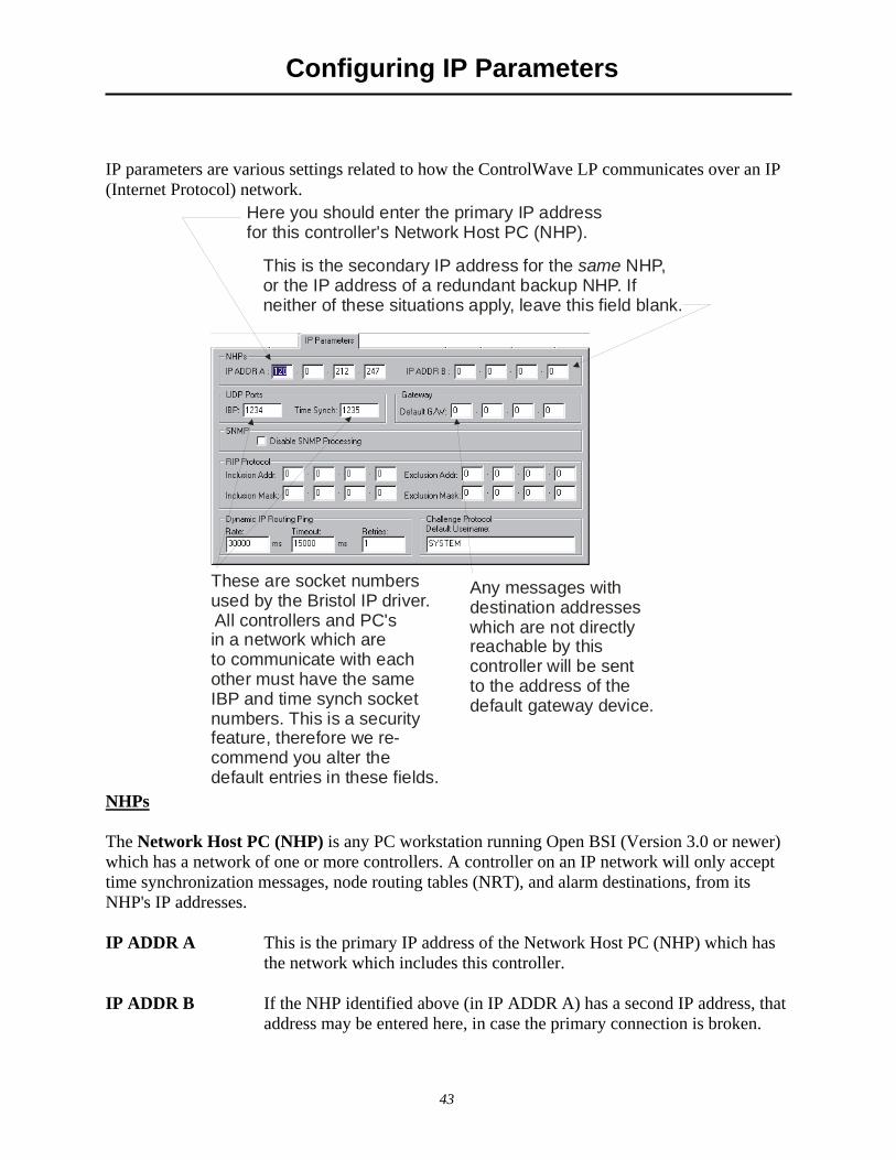
IP parameters are various settings related to how the ControlWave LP communicates over an IP (Internet Protocol) network.
Here you should enter the primary IP addressfor this controller's Network Host PC (NHP).
This is the secondary IP address for the NHP,or the IP address of a redundant backup NHP. Ifneither of these situations apply, leave this field blank.
same
These are socket numbersused by the Bristol IP driver. All controllers and PC's in a network which areto communicate with eachother must have the sameIBP and time synch socketnumbers. This is a securityfeature, therefore we re-commend you alter the default entries in these fields.
Any messages withdestination addresseswhich are not directlyreachable by this controller will be sentto the address of thedefault gateway device.
NHPs The Network Host PC (NHP) is any PC workstation running Open BSI (Version 3.0 or newer) which has a network of one or more controllers. A controller on an IP network will only accept time synchronization messages, node routing tables (NRT), and alarm destinations, from its NHP's IP addresses. IP ADDR A This is the primary IP address of the Network Host PC (NHP) which has
the network which includes this controller. IP ADDR B If the NHP identified above (in IP ADDR A) has a second IP address, that
address may be entered here, in case the primary connection is broken.

Configuring IP Parameters
44
Alternatively, if there is a redundant backup NHP, its address should be entered here. If neither of these cases apply, "IP ADDR B" should be left blank.
UDP Ports UDP ports (sometimes referred to as sockets) have nothing to do with physical communication port hardware. They actually refer to entry points within the UDP communication protocol software (which is an industry standard Internet Protocol). The underlying details of UDP are beyond the scope of this document, but the parameters are included here as a security feature. IBP IBP is the UDP port used by the Bristol IP driver software. Every Open BSI
Workstation and controller in a given network, which need to communicate via IP, MUST share the same IBP UDP socket number. For security purposes, it is recommended that you change the IBP port number to something other than the default value shown. This is particularly important if your network has a connection to the world-wide Internet.
Time Synch This is the UDP port used to send time synchronization messages to controllers.
Every Open BSI Workstation and controller in a given network, which need to communicate via IP, MUST share the same time synch UDP socket number. For security purposes, it is recommended that you change the IBP port number to something other than the default value shown. This is particularly important if your network has a connection to the world-wide Internet.
Gateway Default G/W If this controller receives any messages for which it cannot locate a direct route to
a destination address, it sends them to the default gateway's IP address, as specified in this field. A default gateway is a device (PC workstation, remote process controller, router) which receives these messages, and attempts to route them to their destination.
SNMP, RIP Protocol, Dynamic IP Routing Ping, Challenge Protocol: These IP parameters are used in more complicated network configurations, and to meet certain special IP security requirements. Explanations are beyond the scope of this document. When you are finished making changes in the Flash Configuration Utility: Click on the [Save to Rtu] button, and the new IP parameters will be transferred to FLASH memory in the ControlWave LP. You must then power off the ControlWave LP, then restore power, (as described earlier) for the changes to take effect.

Configuring User Accounts and Privileges
45
onfiguring User Accounts and Privileges
The Security page of the Flash Configuration Utility allows usernames and passwords to be created for ControlWave LP users, and for user privileges to be defined. This allows restrictions to be created on who has access to various features and functions of the ControlWave LP. To access the Security page, click on the ‘Security’ tab.
Adding A New User A ControlWave LP controller can support up to 32 different users. To add a user, enter the user’s name (up to 16 characters long) in the “Username” field, and enter a password (up to 16 characters long) for the user in the “Password” AND “Verify” fields. (The password will not appear as you type it.) IMPORTANT: Some Open BSI programs such as DataView, Downloader, etc. which communicate with the ControlWave LP only support shorter usernames and passwords (10 characters or less for the username, 6 characters or less for the password) so you may want to reduce the length of each username and password to conform to these limits. Also, to communicate with this unit using these programs, passwords must be UPPERCASE. Next, select the privileges for this user by clicking on "Custom" and then select the individual privileges in the “Privileges” list box, so they are highlighted. Alternatively, you can choose "Operator", "Engineer" or "Administrator" for a particular user, which will automatically highlight privileges associated with those user categories. The tables, on the next page, shows the privileges associated with these user categories, and list what all the various privileges mean.

Configuring User Accounts and Privileges
46
When all desired privileges have been selected, click on the [Add] button and the user will be added to the system. NOTE: Every ControlWave LP has a special user called RDB_Max. This user account defines the maximum privileges allowed for RDB protocol messages coming into the ControlWave LP. (RDB is used by programs such as DataView, the Harvester, etc.) You cannot delete the RDB_Max user, or rename it, but you can change its privileges. The table below shows the privileges associated with the Operator, Engineer, and Administrator categories:
Privilege Operator Engineer Administrator Read Data Value T T T Update Data Value T T T Read Flash Files via FTP T T Change / Del Flash Files via FTP T T Read Historical Data T T T Change Last Read Pointers in Audit Info T T Change / Delete Historical Definitions T T Add / Change / Del User Security Info T Modify Soft Switches T T Run Diag to read Memory T Run Diag to write Memory T Read Stat / Diag Info T T T Reset Stat / Crash Blocks T T T Read Application Values T T Write Application Values T T Full Application Access T T Add New Historical Definitions T T
The table, below, describes the meaning of each privilege: Privilege Description Read Data Value Allows this user to read data values from this
controller. Update Data Value Alows this user to change data values in this
controller. Read Flash Files via FTP Allows this user read access (via File Transfer
Protocol) to files stored in this ControlWave LP's Flash memory. This could include the ControlWave boot project, source files (*.ZWT), etc.
Change / Del Flash Files via FTP Allows this user (via File Transfer Protocol) to change or delete files stored in the ControlWave LP's Flash memory. This could include the ControlWave boot project, source

Configuring User Accounts and Privileges
47
files (*.ZWT), etc. Read Historical Data Allows this user to view historical data (Audit /
Archive information) from the controller, either via web pages, or Open BSI DataView.
Change Last Read Pointers in Audit Info Allows the user to delete Audit data from the controller.
Add New Historical Definitions Allows this user the create new archive file definitions, and / or to set up the alarm and event buffers for audit configuration, via the Flash Configuration Utility.
Change / Delete Historical Definitions Allows this user to change or delete historical definitions via the Flash Configuration Utility.
Add / Change / Del User Security Info Allows this user to add, change, or delete information on the security data, via the Flash Configuration Utility security page.
Modify Soft Switches Allows this user to change Soft Switch values on the soft switches page of the Flash Configuration Utility.
Run Diag to read Memory Allows this user to run diagnostics to read memory at the controller.
Run Diag to write Memory Allows this user to run diagnostics to write to memory at the controller.
Read Stat / Diag Info Allows this user to view communication statistics and other information on the Statistics web pages.
Reset Stat / Crash Blocks Allows this user to reset statistics and crash block areas on the Statistics web pages.
Read Application Values Allows this user to read values using the ControlWave Designer OPC Server.
Write Application Values Allows this user to modify values using the ControlWave Designer OPC Server.
Full Application Access Allows this user full privileges to perform debugging operations in ControlWave Designer.

Configuring User Accounts and Privileges
48
Modifying the Privileges of an Existing User To change the privileges of an existing user, select the user’s name from the list of "Usernames" and select / de-select privileges for that user in the “Privileges” list box. When finished making selections, click on the [Modify] push button, and the modified privileges will be stored for that user.
Deleting An Existing User To delete a user from the system, select the User's name from the "Usernames" list and click on the [Delete] push button. NOTE: You CANNOT delete the RDB_Max user. You also cannot delete any user who is currently signed into the ControlWave LP.
When You Have Finished Making Security Changes Unlike many of the other pages in the Flash Configuration Utility, once you click on [Save to Rtu] the changes will take effect immediately. NOTE: When you have finished configuring all of your user accounts, you should make sure the default switch (SW4-3) is turned ON, otherwise the special default security account (SYSTEM) will remain active.
What's Next?
49
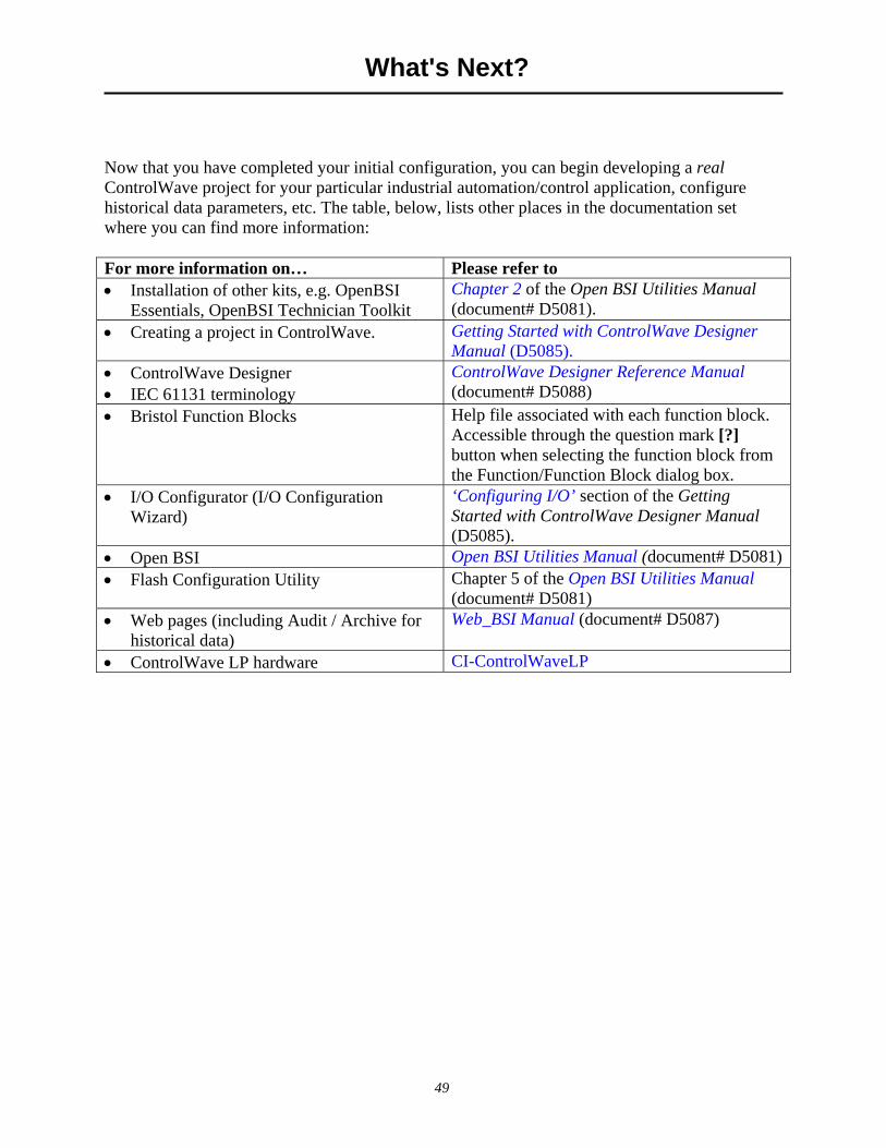
What's Next?
Now that you have completed your initial configuration, you can begin developing a real ControlWave project for your particular industrial automation/control application, configure historical data parameters, etc. The table, below, lists other places in the documentation set where you can find more information: For more information on… Please refer to • Installation of other kits, e.g. OpenBSI
Essentials, OpenBSI Technician Toolkit Chapter 2 of the Open BSI Utilities Manual (document# D5081).
• Creating a project in ControlWave. Getting Started with ControlWave Designer Manual (D5085).
• ControlWave Designer • IEC 61131 terminology
ControlWave Designer Reference Manual (document# D5088)
• Bristol Function Blocks Help file associated with each function block. Accessible through the question mark [?] button when selecting the function block from the Function/Function Block dialog box.
• I/O Configurator (I/O Configuration Wizard)
‘Configuring I/O’ section of the Getting Started with ControlWave Designer Manual (D5085).
• Open BSI Open BSI Utilities Manual (document# D5081)• Flash Configuration Utility Chapter 5 of the Open BSI Utilities Manual
(document# D5081) • Web pages (including Audit / Archive for
historical data) Web_BSI Manual (document# D5087)
• ControlWave LP hardware CI-ControlWaveLP

THIS PAGE INTENTIONALLY LEFT BLANK
Appendix A - Troubleshooting Tips
A-1
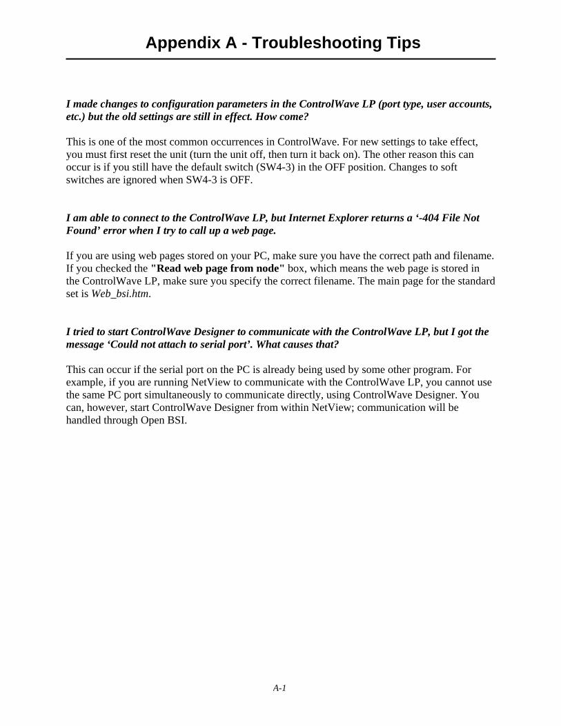
I made changes to configuration parameters in the ControlWave LP (port type, user accounts, etc.) but the old settings are still in effect. How come? This is one of the most common occurrences in ControlWave. For new settings to take effect, you must first reset the unit (turn the unit off, then turn it back on). The other reason this can occur is if you still have the default switch (SW4-3) in the OFF position. Changes to soft switches are ignored when SW4-3 is OFF. I am able to connect to the ControlWave LP, but Internet Explorer returns a ‘-404 File Not Found’ error when I try to call up a web page. If you are using web pages stored on your PC, make sure you have the correct path and filename. If you checked the "Read web page from node" box, which means the web page is stored in the ControlWave LP, make sure you specify the correct filename. The main page for the standard set is Web_bsi.htm. I tried to start ControlWave Designer to communicate with the ControlWave LP, but I got the message ‘Could not attach to serial port’. What causes that? This can occur if the serial port on the PC is already being used by some other program. For example, if you are running NetView to communicate with the ControlWave LP, you cannot use the same PC port simultaneously to communicate directly, using ControlWave Designer. You can, however, start ControlWave Designer from within NetView; communication will be handled through Open BSI.

Quick Setup Guide
D5121 December, 2006
ControlWave LP
The information in this document is subject to change without notice. Every effort has been made to supply complete and accurate information. However, Bristol, Inc. assumes no responsibility for any errors that may appear in this document. If you have comments or questions regarding this manual, please direct them to your local Bristol sales representative, or direct them to one of the addresses listed at left. Bristol, Inc. does not guarantee the accuracy, sufficiency or suitability of the software delivered herewith. The Customer shall inspect and test such software and other materials to his/her satisfaction before using them with important data. There are no warranties, expressed or implied, including those of merchantability and fitness for a particular purpose, concerning the software and other materials delivered herewith. The Emerson logo is a trade mark and service mark of Emerson Electric Co. Other trademarks or copyrighted products mentioned in this document are for information only, and belong to their respective companies, or trademark holders. Copyright (c) 2006, Bristol, Inc., 1100 Buckingham St., Watertown, CT 06795. No part of this manual may be reproduced in any form without the express written permission of Bristol Inc.
Emerson Process Management Bristol, Inc. 1100 Buckingham Street Watertown, CT 06795 Phone: +1 (860) 945-2262 Fax: +1 (860) 945-2525 www.EmersonProcess.com/Bristol Emerson Electric Canada, Ltd. Bristol Canada 6338 Viscount Rd. Mississauga, Ont. L4V 1H3 Canada Phone: 905-362-0880 Fax: 905-362-0882 www.EmersonProcess.com/Bristol Emerson Process Management BBI, S.A. de C.V. Homero No. 1343, 3er Piso Col. Morales Polanco 11540 Mexico, D.F. Mexico Phone: (52-55)-52-81-81-12 Fax: (52-55)-52-81-81-09 www.EmersonProcess.com/Bristol Emerson Process Management Bristol Babcock, Ltd. Blackpole Road Worcester, WR3 8YB United Kingdom Phone: +44 1905 856950 Fax: +44 1905 856969 www.EmersonProcess.com/Bristol Emerson Process Management Bristol, Inc. 22 Portofino Crescent, Grand Canals Bunbury, Western Australia 6230 Mail to: PO Box 1987 (zip 6231) Phone: +61 (8) 9725-2355 Fax: +61 (8) 8 9725-2955 www.EmersonProcess.com/Bristol
Return to the Table of Contents
Return to the List of Manuals