convection steamer w/twin generators … steamer w/twin generators installation - operation -...
TRANSCRIPT
ECO-JETCONVECTION STEAMER W/TWIN GENERATORSINSTALLATION - OPERATION - MAINTENANCE
Telephone: (802) 658-6600 Fax: (802)864-0183www.marketforge.com PN 14-0274 Rev B (1/17)
© 2017 - Market Forge
MODELS
�EJ-10E
Your Service Agency’s Address:Model
Serial number
Oven installed by
Installation checked by
TABLE OF CONTENTS
INSTALLATIONService Connections . . . . . . . . . . . . . . . . . . . . . . . . . . . . . . . . . . . . . . . . . . . . . . . . . . . . . 2Installation Instructions . . . . . . . . . . . . . . . . . . . . . . . . . . . . . . . . . . . . . . . . . . . . . . . . . . . 3
Location . . . . . . . . . . . . . . . . . . . . . . . . . . . . . . . . . . . . . . . . . . . . . . . . . . . . . . . . . . . . 3Leveling and Anchoring . . . . . . . . . . . . . . . . . . . . . . . . . . . . . . . . . . . . . . . . . . . . . . . 3Electrical Connection . . . . . . . . . . . . . . . . . . . . . . . . . . . . . . . . . . . . . . . . . . . . . . . . . 3Plumbing Connections . . . . . . . . . . . . . . . . . . . . . . . . . . . . . . . . . . . . . . . . . . . . . . . . 3Adjustment for High Altitude Locations . . . . . . . . . . . . . . . . . . . . . . . . . . . . . . . . . 3Adjustment for Drain Water Temperature . . . . . . . . . . . . . . . . . . . . . . . . . . . . . . . 3Drain Connections . . . . . . . . . . . . . . . . . . . . . . . . . . . . . . . . . . . . . . . . . . . . . . . . . . . . 4Water Quality . . . . . . . . . . . . . . . . . . . . . . . . . . . . . . . . . . . . . . . . . . . . . . . . . . . . . . . . 4Vent Hood . . . . . . . . . . . . . . . . . . . . . . . . . . . . . . . . . . . . . . . . . . . . . . . . . . . . . . . . . . . 4
Start-Up Test . . . . . . . . . . . . . . . . . . . . . . . . . . . . . . . . . . . . . . . . . . . . . . . . . . . . . . . . . . . . 5
OPERATIONControl Panel . . . . . . . . . . . . . . . . . . . . . . . . . . . . . . . . . . . . . . . . . . . . . . . . . . . . . . . . . . . . 6Operating Instructions . . . . . . . . . . . . . . . . . . . . . . . . . . . . . . . . . . . . . . . . . . . . . . . . . . . . 7
Before First Use . . . . . . . . . . . . . . . . . . . . . . . . . . . . . . . . . . . . . . . . . . . . . . . . . . . . . . 7Preheat . . . . . . . . . . . . . . . . . . . . . . . . . . . . . . . . . . . . . . . . . . . . . . . . . . . . . . . . . . . . . 7Cook . . . . . . . . . . . . . . . . . . . . . . . . . . . . . . . . . . . . . . . . . . . . . . . . . . . . . . . . . . . . . . . . 7Constant Steam Cooking . . . . . . . . . . . . . . . . . . . . . . . . . . . . . . . . . . . . . . . . . . . . . 7Shutdown . . . . . . . . . . . . . . . . . . . . . . . . . . . . . . . . . . . . . . . . . . . . . . . . . . . . . . . . . . . 7Cooking Hints . . . . . . . . . . . . . . . . . . . . . . . . . . . . . . . . . . . . . . . . . . . . . . . . . . . . . . . 7
Suggested Cooking Guidelines . . . . . . . . . . . . . . . . . . . . . . . . . . . . . . . . . . . . . . . . . . . . 8
MAINTENANCECleaning . . . . . . . . . . . . . . . . . . . . . . . . . . . . . . . . . . . . . . . . . . . . . . . . . . . . . . . . . . . . . . . 10
IMPORTANT WARNING: Improper installa-tion, adjustment, alternation, service or maintenance can cause property damage, in-jury or death. Read the instal-lation, operation and mainte-nance instructions thoroughly before installing or servicing this equipment.
FOR YOUR SAFETY
Do not store or use gasoline or other flammable vapors or liq-uids in the vicinity of this or any other appliance.
The information contained in this manual is important for the prop-er installation, use, and mainte-nance of this oven. Adherence to these procedures and instruc-tions will result in satisfactory baking results and long, trou-ble free service. Please read this manual carefully and retain it for future reference.
Adequate clearances must be maintained for safe and proper operation.
ERRORS: Descriptive, typo-graphic or pictorial errors are subject to correction. Specifi-cations are subject to change without notice.
2INSTALLATION
Service Connections
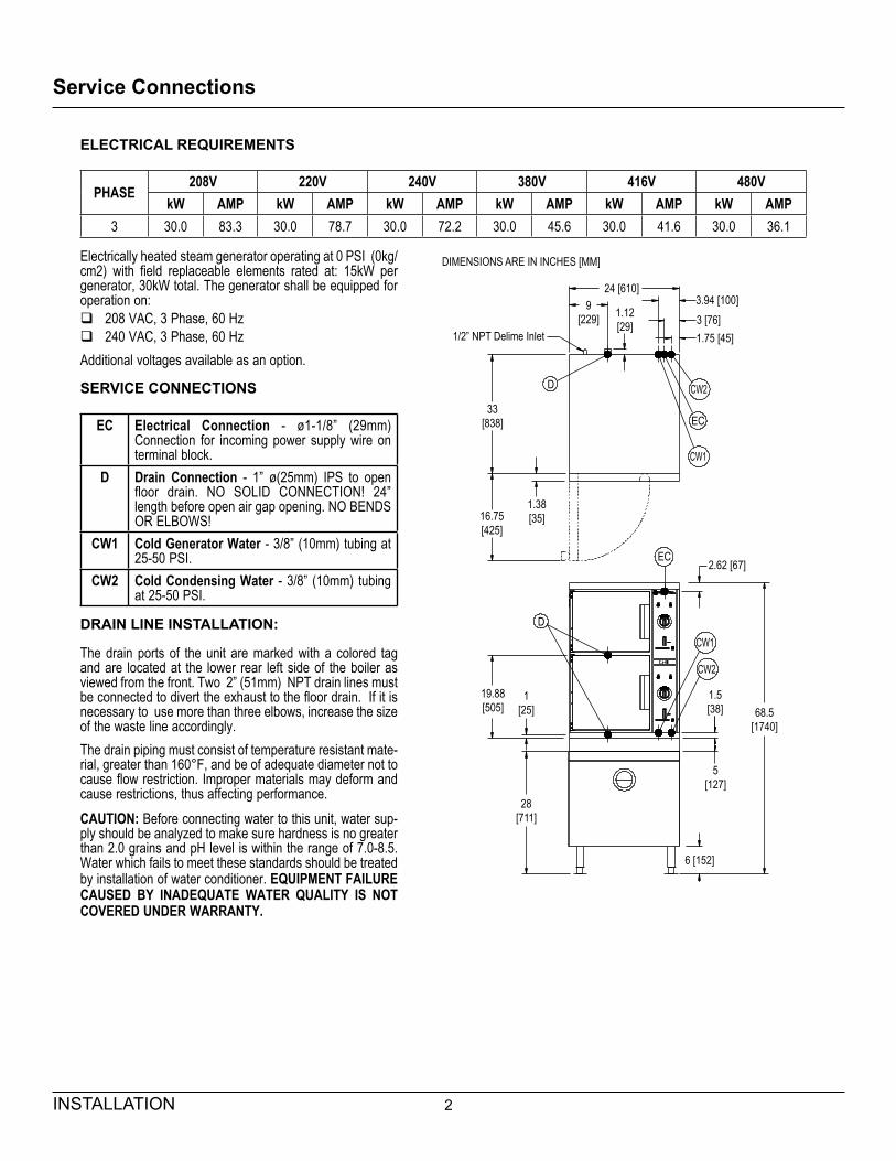
Electrically heated steam generator operating at 0 PSI (0kg/cm2) with field replaceable elements rated at: 15kW per generator, 30kW total. The generator shall be equipped for operation on:
� 208 VAC, 3 Phase, 60 Hz � 240 VAC, 3 Phase, 60 Hz
Additional voltages available as an option.
SERVICE CONNECTIONS
EC Electrical Connection - ø1-1/8” (29mm) Connection for incoming power supply wire on terminal block.
D Drain Connection - 1” ø(25mm) IPS to open floor drain. NO SOLID CONNECTION! 24” length before open air gap opening. NO BENDS OR ELBOWS!
CW1 Cold Generator Water - 3/8” (10mm) tubing at 25-50 PSI.
CW2 Cold Condensing Water - 3/8” (10mm) tubing at 25-50 PSI.
DRAIN LINE INSTALLATION:
The drain ports of the unit are marked with a colored tag and are located at the lower rear left side of the boiler as viewed from the front. Two 2” (51mm) NPT drain lines must be connected to divert the exhaust to the floor drain. If it is necessary to use more than three elbows, increase the size of the waste line accordingly.The drain piping must consist of temperature resistant mate-rial, greater than 160°F, and be of adequate diameter not to cause flow restriction. Improper materials may deform and cause restrictions, thus affecting performance.CAUTION: Before connecting water to this unit, water sup-ply should be analyzed to make sure hardness is no greater than 2.0 grains and pH level is within the range of 7.0-8.5. Water which fails to meet these standards should be treated by installation of water conditioner. EQUIPMENT FAILURE CAUSED BY INADEQUATE WATER QUALITY IS NOT COVERED UNDER WARRANTY.
ELECTRICAL REQUIREMENTS
PHASE208V 220V 240V 380V 416V 480V
kW AMP kW AMP kW AMP kW AMP kW AMP kW AMP3 30.0 83.3 30.0 78.7 30.0 72.2 30.0 45.6 30.0 41.6 30.0 36.1
DIMENSIONS ARE IN INCHES [MM]
24 [610]
1/2” NPT Delime Inlet
9[229] 1.12
[29] 3 [76]3.94 [100]
1.75 [45]
33[838]
D CW2
CW1
EC
16.75[425]
1.38[35]
EC
CW1
CW2
2.62 [67]
1.5[38]
5[127]
28[711]
1[25]
19.88[505] 68.5
[1740]
D
6 [152]
3 INSTALLATION
Installation Instructions
This steamer was inspected before leaving the factory. The transportation company assumes full responsibility for safe delivery upon acceptance of the shipment. Im-mediately after unpacking the steamer, check for possible damage. If the steamer is found to be damaged after un-packing, save the packaging material and contact the car-rier within 15 days of delivery.Prior to installation, verify that the electrical service agrees with the specifications on the machine data plate which is located on the left side panel.
LOCATION Allow space for plumbing and electrical connections. Allow adequate access for operating and servicing the steamer, 36” (915 mm) at the front of the steamer and 15” (381 mm) above the steamer.
LEVELING AND ANCHORING1. Using a spirit level or pan of water in the bottom of the
steamer, adjust the levelling feet to level the steamer front-to-back and side-to-side.
2. Mark hole locations on the floor through the anchor-ing holes provided in the flanged adjustable feet. Re-move the steamer and drill holes at marked locations on the floor. Insert proper anchoring devices.
3. Set steamer back in proper position.
4. Install bolts through anchoring holes and into anchors to secure the steamer to the floor. Seal bolts and flanged feet with Silastic.
5. After the drain is connected, check for level by pour-ing water onto the floor of the compartment. All water should drain through the opening at the back of the compartment cavity.
ELECTRICAL CONNECTION
WARNINGElectrical and grounding connections must comply with applicable portions of the nation-al electrical code and/or other local electrical codes.
WARNINGDisconnect the power supply to the appliance before cleaning or servicing.
Make electrical connection through the 1-1/8” (29 mm) di-ameter hole provided using 3/4” (19 mm) trade size con-duit. Refer to the wiring diagram located inside the right side panel. Use 90°C minimum insulated wire.
PLUMBING CONNECTIONS
WARNINGPlumbing connections must comply with ap-plicable sanitary, safety, and plumbing codes.
The water supply inlets are provided with 3/8” (10 mm) compression fittings for 3/8” O.D. copper tubing. The wa-ter supply line pressure should be 25 - 50 psi (170 - 345 kPa) for each line. The water supply to the generator tank is separate from the water supply to the cooling system where steam is condensed before entering the drain line.Install line strainers (not provided). A manual shutoff valve for each supply line must be provided convenient to the steamer.The drain piping must consist of temperature resistant material, greater than 160°F, and be of adequate diameter not to cause flow restriction. Improper materials may de-form and cause restrictions, thus affecting performance.We recommend treated water feeding the boiler inlet sup-ply, and untreated water feeding the cooling system inlet. Hook-ups are labeled on the back of the steamer.
ADJUSTMENT FOR HIGH ALTITUDE LOCATIONSThe steamer has been factory set so that when it is ON, and during the READY phase, it will maintain water tem-perature in the steam generator tank at approximately 205°F (96°C) (just below water boiling point). However, for high altitude locations, an authorized service agency must adjust the steamer to achieve this temperature.
ADJUSTMENT FOR DRAIN WATER TEMPERATURECooling solenoid valves have been adjusted to yield drain temperatures of 140°F. This will vary depending on in-stall location water supply temperature and pressure. A qualified service person should adjust the cooling sole-noid valves should the drain temperature be other than desired.
4INSTALLATION
Installation Instructions
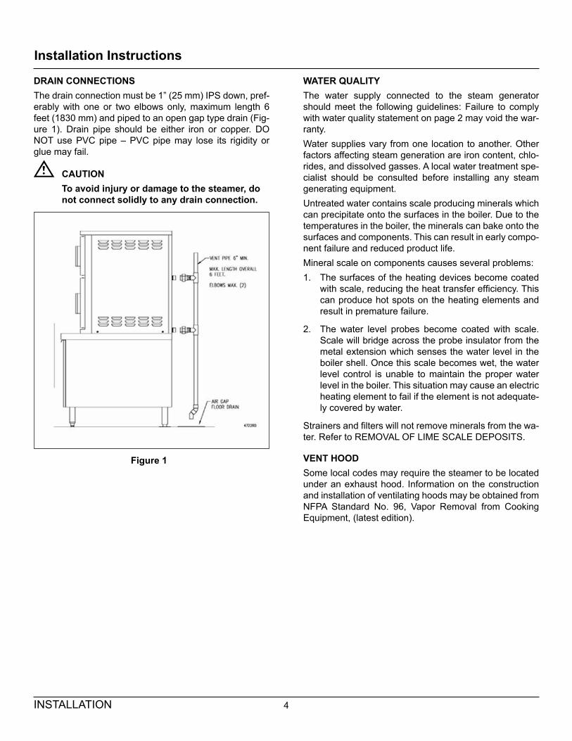
DRAIN CONNECTIONSThe drain connection must be 1” (25 mm) IPS down, pref-erably with one or two elbows only, maximum length 6 feet (1830 mm) and piped to an open gap type drain (Fig-ure 1). Drain pipe should be either iron or copper. DO NOT use PVC pipe – PVC pipe may lose its rigidity or glue may fail.
CAUTIONTo avoid injury or damage to the steamer, do not connect solidly to any drain connection.
Figure 1
WATER QUALITYThe water supply connected to the steam generator should meet the following guidelines: Failure to comply with water quality statement on page 2 may void the war-ranty.Water supplies vary from one location to another. Other factors affecting steam generation are iron content, chlo-rides, and dissolved gasses. A local water treatment spe-cialist should be consulted before installing any steam generating equipment.Untreated water contains scale producing minerals which can precipitate onto the surfaces in the boiler. Due to the temperatures in the boiler, the minerals can bake onto the surfaces and components. This can result in early compo-nent failure and reduced product life.Mineral scale on components causes several problems:1. The surfaces of the heating devices become coated
with scale, reducing the heat transfer efficiency. This can produce hot spots on the heating elements and result in premature failure.
2. The water level probes become coated with scale. Scale will bridge across the probe insulator from the metal extension which senses the water level in the boiler shell. Once this scale becomes wet, the water level control is unable to maintain the proper water level in the boiler. This situation may cause an electric heating element to fail if the element is not adequate-ly covered by water.
Strainers and filters will not remove minerals from the wa-ter. Refer to REMOVAL OF LIME SCALE DEPOSITS.
VENT HOODSome local codes may require the steamer to be located under an exhaust hood. Information on the construction and installation of ventilating hoods may be obtained from NFPA Standard No. 96, Vapor Removal from Cooking Equipment, (latest edition).
5 INSTALLATION
Start-Up Test
WARNINGThe steamer and its parts are hot. Use care when operating, cleaning or servicing the steamer. The cooking compartment contains live steam. Stay clear while opening the door.
Once the steamer is installed and all mechanical connec-tions have been made, thoroughly test the steamer before operation.1. Check that proper water, drain, and electrical connec-
tions have been made.
2. Turn main power switch ON. After approximately 15 minutes, the READY light should come on, indicating that the water temperature is 205°F (96°C).
3. When the READY light comes on, set the timer at 5 minutes. With door open, observe that no steam is entering the compartment and the COOKING light is OFF.
4. Close compartment door. The COOKING light should now be lit and steam should be heard entering the compartment after about 45 seconds (5 minutes if boiler is empty).
5. Check drain line to ensure that water from the cold water condenser is flowing through the drain line.
6. Open compartment door and observe that steam supply to the chamber is cut off (READY light should again come on and COOKING light goes off).
7. Close compartment door and let cooking cycle finish. When the timer returns to the “O” position, a buzzer will sound, signalling the end of the cooking cycle. To silence the buzzer, turn the dial timer to OFF.
8. Complete the above steps for each cooking compart-ment.
9. To shut the steamer down, turn the main power switch OFF and leave the compartment doors slightly open to allow the inside to dry out.
6OPERATION
Control Panel
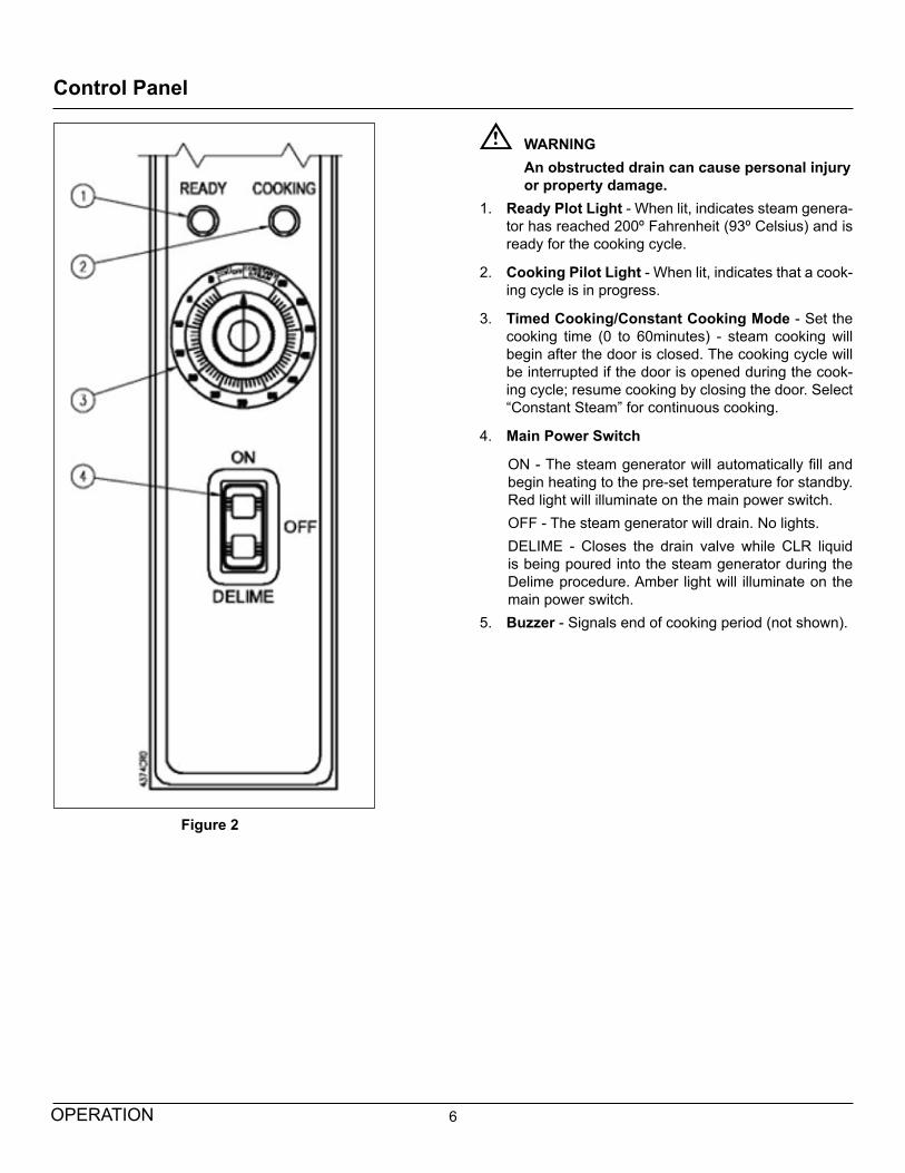
WARNINGAn obstructed drain can cause personal injury or property damage.
1. Ready Plot Light - When lit, indicates steam genera-tor has reached 200º Fahrenheit (93º Celsius) and is ready for the cooking cycle.
2. Cooking Pilot Light - When lit, indicates that a cook-ing cycle is in progress.
3. Timed Cooking/Constant Cooking Mode - Set the cooking time (0 to 60minutes) - steam cooking will begin after the door is closed. The cooking cycle will be interrupted if the door is opened during the cook-ing cycle; resume cooking by closing the door. Select “Constant Steam” for continuous cooking.
4. Main Power Switch
ON - The steam generator will automatically fill and begin heating to the pre-set temperature for standby. Red light will illuminate on the main power switch.OFF - The steam generator will drain. No lights.DELIME - Closes the drain valve while CLR liquid is being poured into the steam generator during the Delime procedure. Amber light will illuminate on the main power switch.
5. Buzzer - Signals end of cooking period (not shown).
Figure 2
7 OPERATION
Operating Instructions
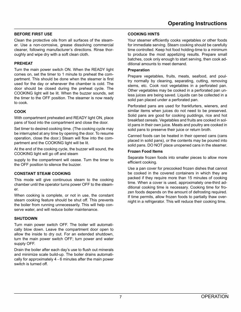
BEFORE FIRST USEClean the protective oils from all surfaces of the steam-er. Use a non-corrosive, grease dissolving commercial cleaner, following manufacturer’s directions. Rinse thor-oughly and wipe dry with a soft clean cloth.
PREHEATTurn the main power switch ON. When the READY light comes on, set the timer to 1 minute to preheat the com-partment. This should be done when the steamer is first used for the day or whenever the chamber is cold. The door should be closed during the preheat cycle. The COOKING light will be lit. When the buzzer sounds, set the timer to the OFF position. The steamer is now ready to cook.
COOKWith compartment preheated and READY light ON, place pans of food into the compartment and close the door.Set timer to desired cooking time. (The cooking cycle may be interrupted at any time by opening the door. To resume operation, close the door.) Steam will flow into the com-partment and the COOKING light will be lit.At the end of the cooking cycle, the buzzer will sound, the COOKING light will go off and steamsupply to the compartment will cease. Turn the timer to the OFF position to silence the buzzer.
CONSTANT STEAM COOKINGThis mode will give continuous steam to the cooking chamber until the operator turns power OFF to the steam-er.When cooking is complete, or not in use, the constant steam cooking feature should be shut off. This prevents the boiler from running unnecessarily. This will help con-serve water, and will reduce boiler maintenance.
SHUTDOWNTurn main power switch OFF. The boiler will automati-cally blow down. Leave the compartment door open to allow the inside to dry out. For an extended shutdown, turn the main power switch OFF; turn power and water supply OFF.Drain the boiler after each day’s use to flush out minerals and minimize scale build-up. The boiler drains automati-cally for approximately 4 - 6 minutes after the main power switch is turned off.
COOKING HINTS Your steamer efficiently cooks vegetables or other foods for immediate serving. Steam cooking should be carefully time controlled. Keep hot food holding-time to a minimum to produce the most appetizing results. Prepare small batches, cook only enough to start serving, then cook ad-ditional amounts to meet demand.PreparationPrepare vegetables, fruits, meats, seafood, and poul-try normally by cleaning, separating, cutting, removing stems, etc. Cook root vegetables in a perforated pan. Other vegetables may be cooked in a perforated pan un-less juices are being saved. Liquids can be collected in a solid pan placed under a perforated pan.Perforated pans are used for frankfurters, wieners, and similar items when juices do not need to be preserved. Solid pans are good for cooking puddings, rice and hot breakfast cereals. Vegetables and fruits are cooked in sol-id pans in their own juice. Meats and poultry are cooked in solid pans to preserve their juice or return broth.Canned foods can be heated in their opened cans (cans placed in solid pans), or the contents may be poured into solid pans. DO NOT place unopened cans in the steamer.Frozen Food ItemsSeparate frozen foods into smaller pieces to allow more efficient cooking.Use a pan cover for precooked frozen dishes that cannot be cooked in the covered containers in which they are packed if they require more than 15 minutes of cooking time. When a cover is used, approximately one-third ad-ditional cooking time is necessary. Cooking time for fro-zen foods depends on the amount of defrosting required. If time permits, allow frozen foods to partially thaw over-night in a refrigerator. This will reduce their cooking time.
8OPERATION
Suggested Cooking Guidelines
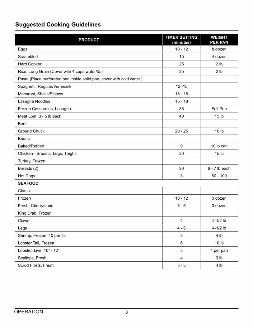
PRODUCT TIMER SETTING (minutes)
WEIGHT PER PAN
Eggs 10 - 12 8 dozen
Scrambled 15 4 dozen
Hard Cooked 25 2 lb
Rice, Long Grain (Cover with 4 cups water/lb.) 25 2 lb
Pasta (Place perforated pan inside solid pan, cover with cold water.)
Spaghetti, Regular/Vermicelli 12 -15
Macaroni, Shells/Elbows 15 - 18
Lasagna Noodles 15 - 18
Frozen Casseroles, Lasagna 35 Full Pan
Meat Loaf, 3 - 5 lb each 40 15 lb
Beef
Ground Chuck 20 - 25 10 lb
Beans
Baked/Refried 9 10 lb can
Chicken - Breasts, Legs, Thighs 20 15 lb
Turkey, Frozen
Breasts (2) 90 6 - 7 lb each
Hot Dogs 3 80 - 100
SEAFOOD
Clams
Frozen 10 - 12 3 dozen
Fresh, Cherrystone 5 - 6 3 dozen
King Crab, Frozen
Claws 4 2-1/2 lb
Legs 4 - 6 4-1/2 lb
Shrimp, Frozen, 10 per lb. 5 4 lb
Lobster Tail, Frozen 6 10 lb
Lobster, Live, 10” - 12” 5 4 per pan
Scallops, Fresh 4 3 lb
Scrod Fillets, Fresh 3 - 5 4 lb
9 OPERATION
Suggested Cooking Guidelines
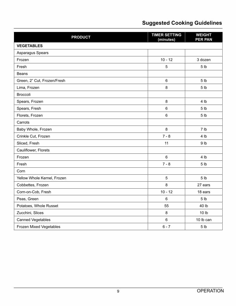
PRODUCT TIMER SETTING (minutes)
WEIGHT PER PAN
VEGETABLES
Asparagus Spears
Frozen 10 - 12 3 dozen
Fresh 5 5 lb
Beans
Green, 2” Cut, Frozen/Fresh 6 5 lb
Lima, Frozen 8 5 lb
Broccoli
Spears, Frozen 8 4 lb
Spears, Fresh 6 5 lb
Florets, Frozen 6 5 lb
Carrots
Baby Whole, Frozen 8 7 lb
Crinkle Cut, Frozen 7 - 8 4 lb
Sliced, Fresh 11 9 lb
Cauliflower, Florets
Frozen 6 4 lb
Fresh 7 - 8 5 lb
Corn
Yellow Whole Kernel, Frozen 5 5 lb
Cobbettes, Frozen 8 27 ears
Corn-on-Cob, Fresh 10 - 12 18 ears
Peas, Green 6 5 lb
Potatoes, Whole Russet 55 40 lb
Zucchini, Slices 8 10 lb
Canned Vegetables 6 10 lb can
Frozen Mixed Vegetables 6 - 7 5 lb
10MAINTENANCE
Cleaning
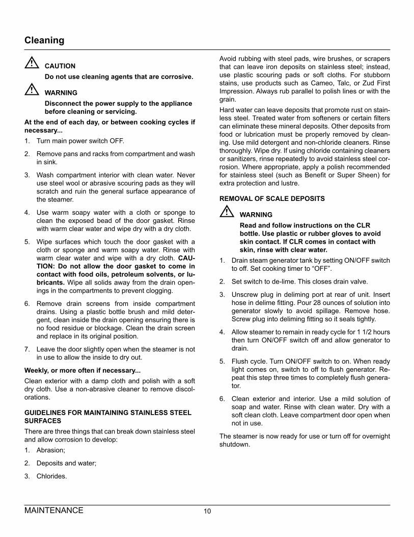
CAUTIONDo not use cleaning agents that are corrosive.
WARNINGDisconnect the power supply to the appliance before cleaning or servicing.
At the end of each day, or between cooking cycles if necessary...1. Turn main power switch OFF.
2. Remove pans and racks from compartment and wash in sink.
3. Wash compartment interior with clean water. Never use steel wool or abrasive scouring pads as they will scratch and ruin the general surface appearance of the steamer.
4. Use warm soapy water with a cloth or sponge to clean the exposed bead of the door gasket. Rinse with warm clear water and wipe dry with a dry cloth.
5. Wipe surfaces which touch the door gasket with a cloth or sponge and warm soapy water. Rinse with warm clear water and wipe with a dry cloth. CAU-TION: Do not allow the door gasket to come in contact with food oils, petroleum solvents, or lu-bricants. Wipe all solids away from the drain open-ings in the compartments to prevent clogging.
6. Remove drain screens from inside compartment drains. Using a plastic bottle brush and mild deter-gent, clean inside the drain opening ensuring there is no food residue or blockage. Clean the drain screen and replace in its original position.
7. Leave the door slightly open when the steamer is not in use to allow the inside to dry out.
Weekly, or more often if necessary...Clean exterior with a damp cloth and polish with a soft dry cloth. Use a non-abrasive cleaner to remove discol-orations.
GUIDELINES FOR MAINTAINING STAINLESS STEEL SURFACESThere are three things that can break down stainless steel and allow corrosion to develop:1. Abrasion;
2. Deposits and water;
3. Chlorides.
Avoid rubbing with steel pads, wire brushes, or scrapers that can leave iron deposits on stainless steel; instead, use plastic scouring pads or soft cloths. For stubborn stains, use products such as Cameo, Talc, or Zud First Impression. Always rub parallel to polish lines or with the grain.Hard water can leave deposits that promote rust on stain-less steel. Treated water from softeners or certain filters can eliminate these mineral deposits. Other deposits from food or lubrication must be properly removed by clean-ing. Use mild detergent and non-chloride cleaners. Rinse thoroughly. Wipe dry. If using chloride containing cleaners or sanitizers, rinse repeatedly to avoid stainless steel cor-rosion. Where appropriate, apply a polish recommended for stainless steel (such as Benefit or Super Sheen) for extra protection and lustre.
REMOVAL OF SCALE DEPOSITS
WARNINGRead and follow instructions on the CLR bottle. Use plastic or rubber gloves to avoid skin contact. If CLR comes in contact with skin, rinse with clear water.
1. Drain steam generator tank by setting ON/OFF switch to off. Set cooking timer to “OFF”.
2. Set switch to de-lime. This closes drain valve.
3. Unscrew plug in deliming port at rear of unit. Insert hose in delime fitting. Pour 28 ounces of solution into generator slowly to avoid spillage. Remove hose. Screw plug into deliming fitting so it seals tightly.
4. Allow steamer to remain in ready cycle for 1 1/2 hours then turn ON/OFF switch off and allow generator to drain.
5. Flush cycle. Turn ON/OFF switch to on. When ready light comes on, switch to off to flush generator. Re-peat this step three times to completely flush genera-tor.
6. Clean exterior and interior. Use a mild solution of soap and water. Rinse with clean water. Dry with a soft clean cloth. Leave compartment door open when not in use.
The steamer is now ready for use or turn off for overnight shutdown.