convective evaporation through water-permeable … · heart rate and plasma osmolality (szlyk, et...
TRANSCRIPT

CONVECTIVE EVAPORATION THROUGH WATER-PERMEABLE MEMBRANES FOR RAPID BEVERAGE CHILLING
Dr. M. Izenson* and Dr. W. Chen, Creare Inc.
Hanover, NH, 03755
C.W. Haering*, J. Sung and D. Pickard U.S. Army Natick Soldier RDEC
Natick, MA, 01760
ABSTRACT
This paper presents the results of a Phase III SBIR project that aims to produce a lightweight, evaporative beverage chiller. Soldiers equipped with this Individual Cooling Element (ICE) will be able to cool their beverages by at least 11°C (20°F) in hot, arid environments where relief from heat stress is critical. Testing and analysis showed that it was feasible to meet performance goals for high cooling power, light weight, reusability and safety.
1. INTRODUCTION
Adequate hydration is critical for soldier health and effectiveness in hot environments; however, water available to soldiers can be hot—possibly too hot to satiate thirst—and can have an unpleasant taste due to disinfectants. Consequently, it is difficult for soldiers to drink enough water for good hydration. If the water could be cooled, then soldiers will drink more. A study conducted by the Army Research Institute of Environmental Medicine (USARIEM) showed that soldiers would consume significantly less water at a temperature of 40°C (104°F) than water at a temperature of 15°C (60°F), resulting in increased rectal temperature, heart rate and plasma osmolality (Szlyk, et al, 1988). Worse, the use of iodine tablets or bleach to purify the water adds an unpleasant taste, increasing the risk that the soldier will not drink. Thus, there is a risk of a cumulative causation—the warmer the environment, the more soldiers need water, but the less likely they are to drink enough to avoid dehydration.
In a desert environment, soldiers are required to drink a surprisingly large amount of water to stay hydrated. The Army field manual on desert survival recommends drinking 0.5 L/hr if the ambient temperature is less than 38°C (100°F) and 1 L/hr if the temperature is over 38°C (Department of the Army, 2002). USARIEM provides guidelines for water consumption based on the
environmental conditions and work level. As summarized in Figure 1, water consumption at a rate of 16 L/day (2 L/hr) is required when performing hard work when the wet bulb globe temperature (WBGT) – a measure that combines temperature, relative humidity and solar radiation – is over 32°C (90°F). The field manual lists the types of heat casualties that may arise from drinking insufficient water—heat cramps, heat exhaustion and/or heat stroke—with consequences ranging from temporary incapacitation to death. The problem is greatly magnified for soldiers who must wear chemical/biological protective suits. Clearly, adequate hydration is critical for maintaining soldier effectiveness.
Figure 1. Daily Water Requirements
Suggested by USARIEM
Creare’s evaporation-based beverage chiller gives individual soldiers the new capability of cooling their drinking water by 11°C (20°F) in hot, arid environments using a compact, lightweight device. In the ICE, a small fraction of the drinking water evaporates to cool the rest of the water using a very compact heat/mass exchanger—providing a “evaporation heat pump.” By using the low humidity environment of the desert, the ICE can impose a large amount of cooling power on the beverage using only a low-wattage fan, achieving a ratio of cooling power to
1

Report Documentation Page Form ApprovedOMB No. 0704-0188
Public reporting burden for the collection of information is estimated to average 1 hour per response, including the time for reviewing instructions, searching existing data sources, gathering andmaintaining the data needed, and completing and reviewing the collection of information. Send comments regarding this burden estimate or any other aspect of this collection of information,including suggestions for reducing this burden, to Washington Headquarters Services, Directorate for Information Operations and Reports, 1215 Jefferson Davis Highway, Suite 1204, ArlingtonVA 22202-4302. Respondents should be aware that notwithstanding any other provision of law, no person shall be subject to a penalty for failing to comply with a collection of information if itdoes not display a currently valid OMB control number.
1. REPORT DATE DEC 2008
2. REPORT TYPE N/A
3. DATES COVERED -
4. TITLE AND SUBTITLE Convective Evaporation Through Water-Permeable Membranes ForRapid Beverage Chilling
5a. CONTRACT NUMBER
5b. GRANT NUMBER
5c. PROGRAM ELEMENT NUMBER
6. AUTHOR(S) 5d. PROJECT NUMBER
5e. TASK NUMBER
5f. WORK UNIT NUMBER
7. PERFORMING ORGANIZATION NAME(S) AND ADDRESS(ES) Creare Inc. Hanover, NH, 03755
8. PERFORMING ORGANIZATIONREPORT NUMBER
9. SPONSORING/MONITORING AGENCY NAME(S) AND ADDRESS(ES) 10. SPONSOR/MONITOR’S ACRONYM(S)
11. SPONSOR/MONITOR’S REPORT NUMBER(S)
12. DISTRIBUTION/AVAILABILITY STATEMENT Approved for public release, distribution unlimited
13. SUPPLEMENTARY NOTES See also ADM002187. Proceedings of the Army Science Conference (26th) Held in Orlando, Florida on 1-4December 2008, The original document contains color images.
14. ABSTRACT
15. SUBJECT TERMS
16. SECURITY CLASSIFICATION OF: 17. LIMITATION OF ABSTRACT
SAR
18. NUMBEROF PAGES
7
19a. NAME OFRESPONSIBLE PERSON
a. REPORT unclassified
b. ABSTRACT unclassified
c. THIS PAGE unclassified
Standard Form 298 (Rev. 8-98) Prescribed by ANSI Std Z39-18

electrical power that is orders of magnitude above and beyond vapor compression refrigeration.
2. DESIGN SPECIFICATION GENERATION
As the design of the beverage chiller is heavily influenced by its specifications, it is important that aspects such as flow rate, average drink size, pressure drop, final temperature, size and weight are accurate.
Soldiers needs were translated into technical specifications for an ICE (Table 1). The ICE must be small enough to fit in a pocket and light enough not to be noticed when worn on the carrier. The device must able to chill an full hydration bag (3.0 liters) by 11°C (20°F), or within 10% of the wet-bulb temperature in 1 hour and must be able to chill water at an instantaneous flow rate of 200 mL/min. Battery power, while undesired, is an acceptable tradeoff for size.
The ICE must operate in ambient desert conditions of 46°C (115ºF) and 10-50% humidity and weigh as little as possible. The maximum weight target was set at 141 g (5 oz). To move so much heat in a device that weighs so little requires (1) use of the most effective water cooling technique and (2) innovative, compact components that enable high rates of heat transfer.
Table 1: ICE Specifications
2.1 Average Drink Rate
Even though the guidelines for hydration in hot, arid environments are 1 L/hr and 2 L/hr by the Army and USARIEM respectively, a design safety factor was implemented to insure performance in all situations. The average rate of 3 L/hr was set as the goal. Three liters is a common size for hydration bags and it is feasible that a user could drink the whole volume in an hour.
2.2 Instantaneous Drinking rate
The rate in which the user drinks can be expressed as an instantaneous flow rate and amount of water per drink. The instantaneous flow rate target was set at 200 mL/min because that is the flow of water though the NBC mask before the user begins to detect back-pressure. Even though the ICE is not to be used in an NBC environment,
this data provides a guideline as to what is acceptable by users.
2.3 Average Drinking Size
The average drink size was based on a unpublished study performed by USARIEM showing typical drinking patterns during heavy work in hot environments. These data were obtained by monitoring the water content in a hydration pack worn by a firefighter during a 13-hour day spent fighting forest fires. Ambient temperature data were also recorded. These data are summarized in Figure 2.
Figure 2. Water Consumption by Firefighters
While Fighting a Forest Fire
The data show that drinking rate tends to vary with the ambient temperature. During this test, the average, hourly ambient temperature reached a maximum of 45–46°C (113–115°F) for two hours. During this extremely hot period, the average drinking rate was 1070–1160 mL/hr and the total volume consumed was 6.3 L. Volumetric water consumption data were recorded by the minute and Figure 3 shows a histogram of these detailed data. Roughly 75% of all drinks were 50 mL/min or less. Only 8% were 60 mL/min or more. The data also suggest that the average drink size was on the order of 30 mL.
Figure 3. Minute Volume Data for a
Firefighter While Fighting a Forest Fire
Quantity of water (L) 3.0 Average Drink Rate (mL/min) 50 Instantaneous Drinking Rate (mL/min) 200 Max Weight (g) 141 Max Ambient temp. (°C) 46 Cooling Desired (°C) 11 Max °C from wet bulb 2.78 Max Δ from wet bulb (%) 10
2
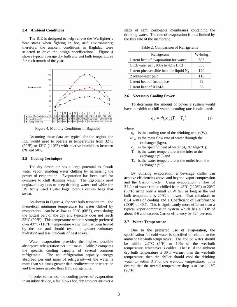
2.4 Ambient Conditions
The ICE is designed to help relieve the Warfighter’s heat stress when fighting in hot, arid environments; therefore, the ambient conditions in Baghdad were selected to drive the design specifications. Figure 4 shows typical average dry bulb and wet bulb temperatures for each month of the year.
Figure 4. Monthly Conditions in Baghdad
Assuming these data are typical for the region, the ICE would need to operate in temperatures from 32°C (90°F) to 43°C (110°F) with relative humidities between 8% and 50%.
2.5 Cooling Technique
The dry desert air has a large potential to absorb water vapor, enabling water chilling by harnessing the power of evaporation. Evaporation has been used for centuries to chill drinking water. The Egyptians used unglazed clay pots to keep drinking water cool while the US Army used Lyster bags, porous canvas bags that sweat.
As shown in Figure 4, the wet bulb temperature—the theoretical minimum temperature for water chilled by evaporation—can be as low as 20°C (68°F), even during the hottest part of the day and typically does not reach 32°C (90°F). This temperature water is strongly preferred over 43°C (110°F) temperature water that has been heated by the sun and should result in greater voluntary hydration and less incidents of heat stress.
Water evaporation provides the highest possible absorptive refrigeration per unit mass. Table 2 compares the specific cooling capacity of several common refrigerants. The net refrigeration capacity—energy absorbed per unit mass of refrigerant—of the water is more than six times greater than zeolite/water or water ice and five times greater than HFC refrigerants.
In order to harness the cooling power of evaporation in an inline device, a fan blows hot, dry ambient air over a
stack of semi permeable membranes containing the drinking water. The rate of evaporation is thus limited by the flux rate of the membrane.
Table 2: Comparison of Refrigerants
2.6 Necessary Cooling Power
To determine the amount of power a system would have to exhibit to chill water, a cooling rate is calculated:
)( oipwr TTcmq −= & (1)
where: qr is the cooling rate of the drinking water (W), m& w is the mass flow rate of water through the
exchanger (kg/s), cp is the specific heat of water (4,187 J/kg-°C), Ti is the water temperature at the inlet to the
exchanger (°C) and To is the water temperature at the outlet from the
exchanger (°C).
By utilizing evaporation, a beverage chiller can achieve efficiencies above and beyond vapor compression and the Carnot Cycle. Using evaporation, a flow of 3 L/hr of water can be chilled from 43°C (110°F) to 20°C (68°F) using only a small 2.0W fan, as long as the wet bulb temperature is 20°C or lower. That calculates to 81.4 watts of cooling and a Coefficient of Performance (COP) of 40.7. This is significantly more efficient than a typical vapor-compression system which has a COP of about 3-6 and exceeds Carnot efficiency by 324 percent.
2.7 Water Temperature
Due to the preferred use of evaporation, the specification for cold water is specified in relation to the ambient wet-bulb temperature. The cooled water should be within 2.7°C (5°F) or 10% of the wet-bulb temperature, whichever is colder. That is, if the ambient dry bulb temperature is 30°F warmer than the wet-bulb temperature, then the chiller should cool the drinking water to within 3°F of the wet-bulb temperature. It is desired that the overall temperature drop is at least 11°C (20°F).
Refrigerant W-hr/kg Latent heat of evaporation for water 695 LiCl/water pair, 90% to 42% LiCl 333 Latent plus sensible heat for liquid N2 120 Zeolite/water pair 116 Latent heat of fusion, ice 92 Latent heat of R134A 63
3
3. DESIGN CONCEPT
The physical configuration of the ICE is an inline system intended to integrate with the hydration system and its add-on components such as in-line filters. An artists concept is shown in Figure 5. The arrows show how the ICE cools the drinking water as the user draws water from the bag using his mouth. The device could either clip to the hydration carrier as shown, to the MOLLE, or possibly to the cap on the hydration bag.
Figure 5: Individual Cooling Element (ICE)
3.1 The Use of Membranes
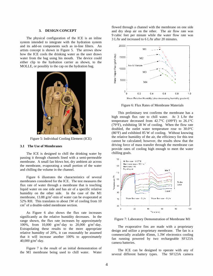
The ICE is designed to chill the drinking water by passing it through channels lined with a semi-permeable membrane. A small fan blows hot, dry ambient air across the membrane, evaporating a small portion of the water and chilling the volume in the channel.
Figure 6 illustrates the characteristics of several membranes considered for the ICE. The test measures the flux rate of water through a membrane that is touching liquid water on one side and has air of a specific relative humidity on the other side. In the case of the M1 membrane, 13.88 g/m2-min of water can be evaporated at 52% RH. This translates to about 1W of cooling from 10 cm2 of a double-sided membrane section.
As Figure 6 also shows the flux rate increases significantly as the relative humidity decreases. In the range shown, the flux rate increases by approximately 100%, from 10,000 g/m2-day to 20,000 g/m2-day. Extrapolating these results to the more appropriate relative humidity of 20%, it can reasonably be assumed that it will increase another 100% to approximately 40,000 g/m2-day.
Figure 7 is the result of an initial demonstration of the M1 membrane being used to chill water. Water
flowed through a channel with the membrane on one side and dry shop air on the other. The air flow rate was 9 cubic feet per minute while the water flow rate was 3 L/hr and increased to 6 L/hr after 20 minutes.
Figure 6: Flux Rates of Membrane Materials
This preliminary test confirms the membrane has a high enough flux rate to chill water. At 3 L/hr the temperature decreased from 42.7°C (109°F) to 26.1°C (79°F), exhibiting 58 W of cooling. When the flow rate doubled, the outlet water temperature rose to 30.0°C (86°F) and exhibited 85 W of cooling. Without knowing the relative humidity of the air, the efficiency for this test cannot be calculated; however, the results show that the driving force of mass transfer through the membrane can provide rates of cooling high enough to meet the water chilling goals.
Figure 7: Laboratory Demonstration of Membrane M1
The evaporative fins are made with a proprietary design and utilize a proprietary membrane. The fan is a commercially available 45mm, 1.3W electronics cooling fan running powered by two rechargeable SF123A camera batteries.
The ICE can be designed to operate with any of several different battery types. The SF123A camera
M1
M2
M3
M4
M1
4

battery suited this application due to its compact size, high energy density and wide availability; it can be found in the Army logistics system or in retail outlets. Other specialty batteries such as the Ultralife® lithium Ion battery could be chosen for their larger energy density, or standard AA batteries could be chosen for their overall availability.
Figure 8 is a photograph of a functional ICE prototype and Table 3 lists some overall design parameters. The evaporative fins are made with a proprietary design and utilize a proprietary membrane. The fan is a typical 45mm, 1.3W electronics cooling fan running off of two rechargeable SF123A camera batteries. A PCT patent application for this design (No. PCT/US08/6247) was submitted on July 8, 2008.
Figure 8: The ICE Prototype
Table 3: ICE Prototype Design Parameters
Height (cm) 8.6 Width, min (cm) 10.8 Width, max (cm) 12.4 Battery mass (g) 16 Total mass (g) 270 Water volume (cm3) 54
4. TESTING
The assembled ICE prototype was tested for performance in a bench scale environmental control system that simulated operation in hot, humid conditions. The prototype operated inside a small chamber supplied with a once-through flow of air at controlled temperature and relative humidity. Air from a shop compressor flowed through a pressure regulator, a flow meter and then through an array of bubblers in a temperature-
controlled water bath. Water-saturated air then flowed through a process heater and into the test chamber. By maintaining the bath at the dew point temperature and the air leaving the process heater at the dry bulb temperature that corresponded to the desired test conditions, the ICE prototype could be tested at any desired combination of dry bulb temperature and level of relative humidity.
As shown in Figure 9, water flowed through the ICE from an elevated reservoir that was maintained at a constant fill level using a pump and float valve. On its way to the ICE, the water flows through a small heat exchanger where its temperature was raised to the desired test conditions. The water then flows through the ICE, cools by evaporation, then enters a flexible tube and flows out of the test chamber. The flow rate of water through the ICE was measured using a graduated cylinder and timer and the flow rate was controlled by changing the level of the supply reservoir. Since the exit tube has a small diameter and runs full, the pressure at the exit of the ICE was controlled by changing the elevation of the tube outlet relative to the ICE.
Figure 9: Bench-Top Environmental Chamber for Testing ICE Performance
The efficiency of the exchanger was assessed by comparing the measured change in water temperature to the maximum possible change, which occurs when the water exit temperature dropped all the way to the wet bulb temperature. To quantify this efficiency, the wet bulb effectiveness was calculated as follows:
wbi
oiwb TT
TT−−
=ε (2)
Where:
εwb is the wet bulb effectiveness and Twb is the wet bulb temperature of the ambient air (°C) Just as in the preliminary tests, these more advanced
test show at low flow rates such as 3 L/hr (0.83 g/s), the
5

water exited the exchanger very close to the wet bulb temperature and the wet bulb effectiveness was essentially 100% (experimental error causes some computed values to slightly exceed 100%). As shown in Figure 10, the wet bulb effectiveness changed significantly as the flow rate increased, dropping to about 80% for a flow rate of 6 L/hr (1.67 g/s) and 60–65% for flows of 9 L/hr (2.5 g/s). The differences in the water temperature drop were proportionally smaller than the increases in flow rate and the actual cooling power increased with increasing flow. So while the cooling power was only about 50 W for a flow of 3 L/hr, the cooling power increased to 85 W and then to over 100 W for flow rates of 6 and 9 L/hr, respectively.
Figure 10: ICE Performance: Power and Effectiveness T = 43°C (110°F), RH = 35%, Twb = 29°C (85°F)
Figure 11 shows the results of a series of tests of the functional prototype under various ambient and operating conditions. Under nominal operating conditions–50 g/min water flow, 226-340 L/min (8-12 ft3/min) air flow, and wet bulb temperatures in the range 23-31°C (73-88°F), the wet-bulb effectiveness of the chiller increases slightly with the ambient dry bulb temperature, approaching 100% for dry bulb temperatures of 48°C (118°F). The effectiveness decreases significantly at higher flow rates of water, although as shown in Figure 10 the cooling power actually increases.
Four tests were conducted with no air flow through some of the heat/mass exchanger (open symbols in Figure 11). Tape was placed over the air inlets to the blocked channels, preventing air from flowing into the top-most channels in the exchanger.
Two of the tests were run with three of ten channels blocked and two were run with five channels blocked. Surprisingly, these tests showed even higher levels of wet bulb effectiveness than the tests with all air channels open.
Figure 11: Wet Bulb Effectiveness for Varying Ambient Temperature, Water Flow Rate
and Number of Air Channels
It is not understood why this might be so; however, the effect was quite repeatable. Possibly larger air velocity across the channels with the warmest water led to more effective mass transfer. Regardless of the reason, it shows the potential for further decreasing the size of the heat/mass exchanger.
4.1 Intermittent Flow Rates
A series of tests were conducted to simulate intermittent drinking by stopping flow for one minute, then allowing a high flow of water through the chiller. Figure 12 shows that during the stagnant periods between drinks, the water in the exchanger cooled rapidly to the wet bulb temperature. As long as the size of the drink did not exceed the volume of water in the exchanger, 54 mL or about 1.8 fl oz, the temperature of the drinking water during the rapid “drink” was equal to the wet bulb temperature regardless of the flow rate. Therefore the evaporation chiller is well-suited for typical use in the field.
Figure 12: Cooling Performance During Intermittent Flow
6

4.2 Pressure Drop
The pressure drop was measured with steady water flow through the chiller. Figure 13 shows the results. At the nominal, steady flow rate of 50 mL/min the pressure loss was very small; about 7.6 cm. H2O. The pressure loss increases with increasing flow rate and reaches about 38 cm. H2O at 135 mL/min and 96.5 cm. H2O at 210 mL/min. The pressure drops due to water flow through the chiller are relatively small and well within the range of typical drinking suctions.
Flow Rate (mL/min)
0 50 100 150 200 250
Pre
ssur
e D
rop
(in. H
2O)
0
10
20
30
40
IBC Prototype 1Calculated for tube ∅0.072 × 13.5 in.
Figure 13: Pressure Losses Due to Water Flow Through the ICE Prototype
4.3 Battery Life
The voltage of the two SF123A batteries was measured periodically during the test series. Figure 13 plots the measured voltages as a function of on-time after the start of testing. The two batteries in series produced a voltage near 6 V at the start of the tests, corresponding to their nominal 3 V rating. The total voltage decreased to 5 V after 200 minutes of continuous operation. After 350 minutes, the combined voltage fell to 3 V and the fan would no longer operate. There was no decrease in performance of the ICE during the last 60 min of the test.
Figure 14: Voltage of SF-123 Batteries During Continuous Operation
CONCLUSIONS
A compact water chiller can play an important role promoting good hydration for soldiers in the field. A functional prototypical evaporative water chiller has been designed, assembled and tested. It is compact, lightweight, consumes, little power and effectively cools drinking water to the ambient wet bulb temperature. The prototype exceeds some performance goals and shows the potential for making future models even smaller. In intermittent flow mode, the chiller rapidly cools water in the flow channels to the wet bulb temperature, enabling the user to take very rapid drinks of cool water up to about 30 mL each. The suction needed to draw large flows of water through the device are relatively small (less than 96.5 in. H2O at a flow rate of 210 mL/min).
Future work will focus on optimizing the materials and heat/mass exchanger design, developing methods to assemble a robust heat/mass exchanger using techniques that are suitable for high-volume manufacture, building several working prototypes and conducting user testing in a desert environment.
ACKNOWLEDGEMENTS
The authors would like to acknowledge the work of Michael Boh of Creare, Inc., Claire King of Propel, Doug Haun of Creare and Greg Kreinsen of the U.S. Army Natick Soldier RDEC.
This work was funded by the Combat Feeding Directorate at the Army Natick Soldier System Center (Natick, MA) under contracts W911QY-05-C-008 and W911QY-08-C-0022 and the Naval Facilities Engineering Command (Port Hueneme, CA) under contract M67854-08-C-6528.
REFERENCES
Department of the Army, 2002: Ch 13, Desert Survival. Army Field Manual 3-05.70 – Survival, 125-132.
Szlyk, P.C., Sils, I.V., Francesconi, R.P., Hubbard, R.W.,
Armstrong, L.E., 1988: Palatability of Drinking Water: Effects on Voluntary Dehydration, USARIEM Tech Rep. AD-A194 596, 29 pp.
7