conventional fitting of an unconventional orthosis
TRANSCRIPT
Conventional Fitting of an Unconventional Orthosis by Donald L. Fornuff, CP.
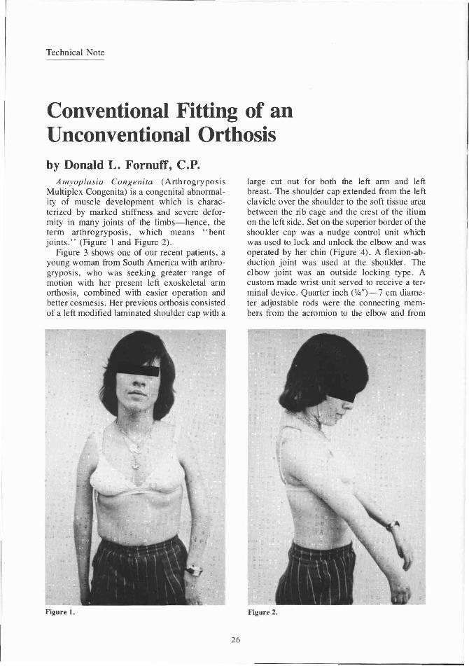
Amyoplasia Congenita (Arthrogryposis Multiplex Congenita) is a congenital abnormality of muscle development which is characterized by marked stiffness and severe deformity in many joints of the limbs—hence, the term arthrogryposis, which means "bent joints." (Figure 1 and Figure 2).
Figure 3 shows one of our recent patients, a young woman from South America with arthrogryposis, who was seeking greater range of motion with her present left exoskeletal arm orthosis, combined with easier operation and better cosmesis. Her previous orthosis consisted of a left modified laminated shoulder cap with a
large cut out for both the left arm and left breast. The shoulder cap extended from the left clavicle over the shoulder to the soft tissue area between the rib cage and the crest of the ilium on the left side. Set on the superior border of the shoulder cap was a nudge control unit which was used to lock and unlock the elbow and was operated by her chin (Figure 4). A flexion-abduction joint was used at the shoulder. The elbow joint was an outside locking type. A custom made wrist unit served to receive a terminal device. Quarter inch (1/4")—7 cm diameter adjustable rods were the connecting members from the acromion to the elbow and from
Figure 1. Figure 2.
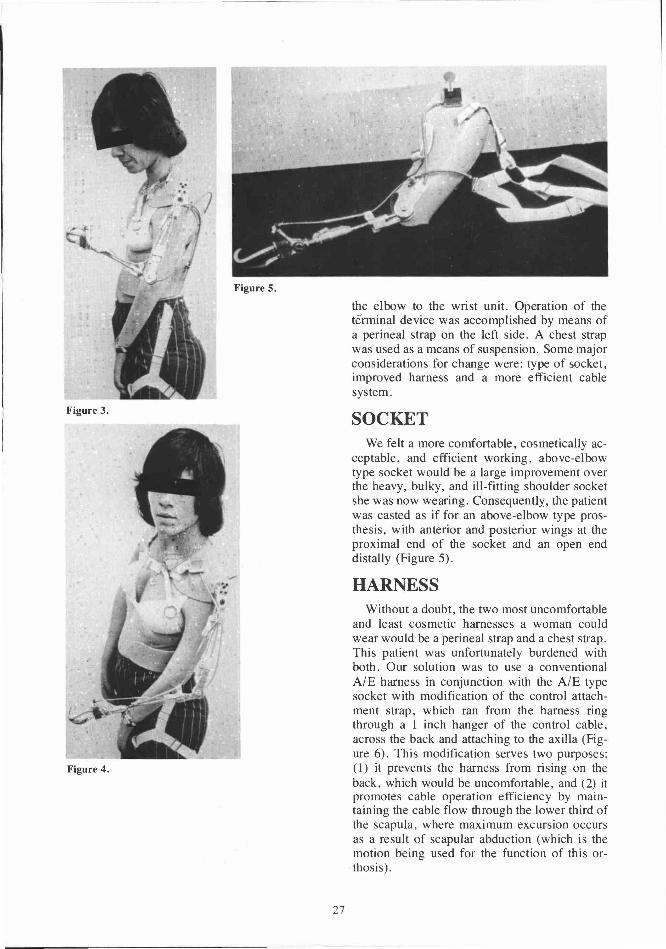
the elbow to the wrist unit. Operation of the terminal device was accomplished by means of a perineal strap on the left side. A chest strap was used as a means of suspension. Some major considerations for change were: type of socket, improved harness and a more efficient cable system.
SOCKET We felt a more comfortable, cosmetically ac
ceptable, and efficient working, above-elbow type socket would be a large improvement over the heavy, bulky, and ill-fitting shoulder socket she was now wearing. Consequently, the patient was casted as if for an above-elbow type prosthesis, with anterior and posterior wings at the proximal end of the socket and an open end distally (Figure 5).
HARNESS Without a doubt, the two most uncomfortable
and least cosmetic harnesses a woman could wear would be a perineal strap and a chest strap. This patient was unfortunately burdened with both. Our solution was to use a conventional A/E harness in conjunction with the A/E type socket with modification of the control attachment strap, which ran from the harness ring through a 1 inch hanger of the control cable, across the back and attaching to the axilla (Figure 6). This modification serves two purposes: (1) it prevents the harness from rising on the back, which would be uncomfortable, and (2) it promotes cable operation efficiency by maintaining the cable flow through the lower third of the scapula, where maximum excursion occurs as a result of scapular abduction (which is the motion being used for the function of this orthosis).
Figure 3 .
Figure 4.
Figure 5.
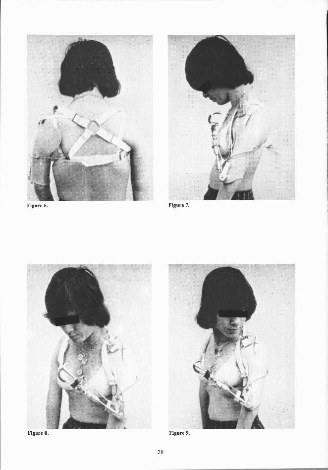
Figure 6. Figure 7.
Figure 8. Figure 9.
CABLE CONTROL SYSTEM A conventional A/E dual control system was
used (Figures 7 and 8).
ELBOW LOCK CONTROL Operation of the elbow lock (E-500 outside
locking joints) was facilitated by slight modification of the locking mechanism. Instead of using an elbow lock strap, the cable from the elbow lock was attached proximally to a nudge control unit similar to what was used on her previous orthosis (Figure 9).
FOREARM The forearm consisted of a threaded
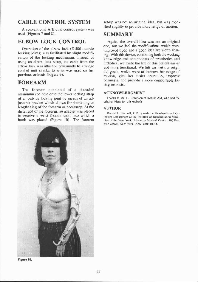
aluminum rod held onto the lower locking strap of an outside locking joint by means of an adjustable bracket which allows for shortening or lengthening of the forearm as necessary. At the distal end of the forearm, an adapter was placed to receive a wrist flexion unit, into which a hook was placed (Figure 10). The forearm
set-up was not an original idea, but was modified slightly to provide more range of motion.
SUMMARY Again, the overall idea was not an original
one, but we feel the modifications which were improved upon and a good idea are worth sharing. With this device, combining both the working knowledge and components of prosthetics and orthotics, we made the life of this patient easier and more functional. We felt we met our original goals, which were to improve her range of motion, give her easier operation, improve cosmesis, and provide a more comfortable fitting orthosis.
ACKNOWLEDGMENT Thanks to Mr. G. Robinson of Robins Aid, who had the
original ideas for this orthosis.
AUTHOR Donald L. Fornuff, CP. is with the Prosthetics and Or
thotics Department at the Institute of Rehabilitation Medicine of the New York University Medical Center, 400 East 34th Street, New York, New York 10016.
Figure 10.