converging the data network with voip fundamentals
TRANSCRIPT
Nortel Communication Server 1000
Converging the Data Networkwith VoIP Fundamentals
NN43001-260.
Document status: StandardDocument version: 01.01Document date: 30 May 2007
Copyright © 2003-2007, Nortel NetworksAll Rights Reserved.
Sourced in Canada.
The information in this document is subject to change without notice. The statements, configurations, technicaldata, and recommendations in this document are believed to be accurate and reliable, but are presented withoutexpress or implied warranty. Users must take full responsibility for their applications of any products specified in thisdocument. The information in this document is proprietary to Nortel Networks.
Nortel, the Nortel Logo, the Globemark, SL-1, Meridian 1, and Succession are trademarks of Nortel Networks.All other trademarks are the property of their respective owners.
3
Revision history
May 2007Standard 01.01. This document is issued to support Nortel CommunicationServer 1000 Release 5.0. This document is renamed Converging the DataNetwork with VoIP Fundamentals (NN43001-260) and contains informationpreviously contained in the following legacy document, now retired:Converging the Data Network with VoIP (553-3001-160).
November 2006Standard 6.00. This document is up-issued for CR Q01456113, addingexplanations and examples of graphical and text XAS configuration strings.
Nortel Communication Server 1000Converging the Data Network with VoIP Fundamentals
NN43001-260 01.01 StandardRelease 5.0 30 May 2007
Copyright © 2003-2007, Nortel Networks
.

4 Revision history
Nortel Communication Server 1000Converging the Data Network with VoIP Fundamentals
NN43001-260 01.01 StandardRelease 5.0 30 May 2007
Copyright © 2003-2007, Nortel Networks
.
5
Contents
How to get help 9Getting help from the Nortel Web site 9Getting help over the telephone from a Nortel Solutions Center 9Getting help from a specialist by using an Express Routing Code 9Getting help through a Nortel distributor or reseller 10
Introduction 11Subject 11Applicable Systems 11Intended audience 12Conventions 13Related information 13
Overview 15Contents 15Introduction 15Network convergence 17Network design 19Quality of Service 20Network performance measurement and monitoring 21Available tools 22Achieving satisfactory voice quality 22
Network design assessment 25Contents 25Introduction 26Network modeling 26LAN and WAN platforms 30Protocols in use 32Link speeds 33Link types 34Link utilization assessment 35Traffic flows in the network 37Service level agreements 38Summary 39
Nortel Communication Server 1000Converging the Data Network with VoIP Fundamentals
NN43001-260 01.01 StandardRelease 5.0 30 May 2007
Copyright © 2003-2007, Nortel Networks
.
6 Contents
QoS mechanisms 41Contents 41Introduction 42The QoS process 46WAN QoS mechanisms 49Layer 2 (Ethernet) QoS 56Layer 3 QoS 61Layer 4 (TCP/IP) classification 68Policy management 69Bandwidth Management 69
Network performance measurement 83Contents 83Introduction 84Network performance measurement tools 91Network availability 91Media Security 92Bandwidth 93Delay 107Jitter 116Packet loss 120Network delay and packet loss evaluation example 123Estimate voice quality 124Does the intranet provide expected voice quality? 129
Server LAN design 131Contents 131Introduction 132Ethernet requirements 142IP address requirements 147Guidelines for configuring a routable ELAN subnet 153Redundant LAN design 154Distributed IP Expansion Media Gateway requirements 160Distributed Media Gateway 1000E 164Campus-distributed Media Gateway enhancements 164Sample system layout 166
Configuration of the DHCP server 173Contents 173Overview 173IP Phones 174Configuring the DHCP server to support full DHCP mode 175
Operating the VoIP network 185Contents 185
Nortel Communication Server 1000Converging the Data Network with VoIP Fundamentals
NN43001-260 01.01 StandardRelease 5.0 30 May 2007
Copyright © 2003-2007, Nortel Networks
.
Contents 7
System management 185Network monitoring 187Network Management 207
Appendix A Subnet mask conversion 211
Appendix B Port number tables 213Contents 213Introduction 213
Appendix C DHCP supplemental information 231Contents 231Introduction to DHCP 231IP acquisition sequence 235IP Phone support for DHCP 239
Appendix D Setup and configuration of DHCP servers 245Contents 245Install a Windows NT 4 or Windows 2000 server 245Configure a Windows NT 4 server with DHCP 246Configure a Windows 2000 server with DHCP 248Install ISC DHCP Server 252Configure ISC DHCP Server 252Install and configure a Solaris 2 server 256
List of terms 259
ProceduresProcedure 1 Assessing link utilization 36Procedure 2 Configuring 802.1p priority bits in
Element Manager 58Procedure 3 Calculating bandwidth amount for bandwidth
zones table 79Procedure 4 Determining intrazone bandwidth 79Procedure 5 Evaluating network performance: overview 86Procedure 6 Calculating LAN traffic 95Procedure 7 Calculating WAN traffic 97Procedure 8 Determining network requirements: overview 100Procedure 9 Converting a subnet mask from CIDR format
to dotted decimal format 211Procedure 10 Launching the DHCP Manager In Windows NT 4 246Procedure 11 Launching the DHCP Manager in Windows 2000 248Procedure 12 Configuring ISC DHCP server 253Procedure 13 Configuring a Solaris 2 server 256Procedure 14 Configuring Solaris 2 to work with IP Phones 256
Nortel Communication Server 1000Converging the Data Network with VoIP Fundamentals
NN43001-260 01.01 StandardRelease 5.0 30 May 2007
Copyright © 2003-2007, Nortel Networks
.

8 Contents
Nortel Communication Server 1000Converging the Data Network with VoIP Fundamentals
NN43001-260 01.01 StandardRelease 5.0 30 May 2007
Copyright © 2003-2007, Nortel Networks
.
9
How to get help
This chapter explains how to get help for Nortel products and services.
Getting help from the Nortel Web site
The best way to get technical support for Nortel products is from the NortelTechnical Support Web site: www.nortel.com/support
This site provides quick access to software, documentation, bulletins, andtools to address issues with Nortel products. From this site, you can:
• download software, documentation, and product bulletins
• search the Technical Support Web site and the Nortel Knowledge Basefor answers to technical issues
• sign up for automatic notification of new software and documentationfor Nortel equipment
• open and manage technical support cases
Getting help over the telephone from a Nortel Solutions Center
If you do not find the information you require on the Nortel Technical SupportWeb site, and you have a Nortel support contract, you can also get helpover the telephone from a Nortel Solutions Center.
In North America, call 1-800-4NORTEL (1-800-466-7835).
Outside North America, go to the following Web site to obtain the telephonenumber for your region:
www.nortel.com/callus
Getting help from a specialist by using an Express Routing Code
Nortel Communication Server 1000Converging the Data Network with VoIP Fundamentals
NN43001-260 01.01 StandardRelease 5.0 30 May 2007
Copyright © 2003-2007, Nortel Networks
.
10 How to get help
To access some Nortel Technical Solutions Centers, you can use an ExpressRouting Code (ERC) to quickly route your call to a specialist in your Nortelproduct or service. To locate the ERC for your product or service, go to:
www.nortel.com/erc
Getting help through a Nortel distributor or reseller
If you purchased a service contract for your Nortel product from a distributoror authorized reseller, contact the technical support staff for that distributoror reseller.
Nortel Communication Server 1000Converging the Data Network with VoIP Fundamentals
NN43001-260 01.01 StandardRelease 5.0 30 May 2007
Copyright © 2003-2007, Nortel Networks
.
11
Introduction
This document is a global document. Contact your system supplier or yourNortel representative to verify that the hardware and software describedare supported in your area.
SubjectThe purpose of this document is to provide direction in ensuring that the datanetwork has been properly provisioned to support IP Telephony services.
Note on legacy products and releasesThis NTP contains information about systems, components, and featuresthat are compatible with Nortel Communication Server 1000 Release 4.5software. For more information on legacy products and releases, click theTechnical Documentation link under Support & Training on the Nortelhome page:
www.nortel.com
Applicable SystemsThis document applies to the following systems:
• CS 1000E CP PII
• CS 1000E CP PIV
• CS 1000E CP PM HA (Chassis)
• CS 1000E CP PM HA (Cabinet)
• CS 1000E CP PM SA (Chassis)
• CS 1000E CP PM SA (Cabinet)
• CS 1000M Single Group CP PII (AC/DC)
• CS 1000M Multi Group CP PII (AC/DC)
• CS 1000M Single Group CP PIV (AC/DC)
• CS 1000M Multi Group CP PIV (AC/DC)
Nortel Communication Server 1000Converging the Data Network with VoIP Fundamentals
NN43001-260 01.01 StandardRelease 5.0 30 May 2007
Copyright © 2003-2007, Nortel Networks
.
12 Introduction
Note: When upgrading software, memory upgrades may be required onthe Signaling Server, the Call Server, or both.
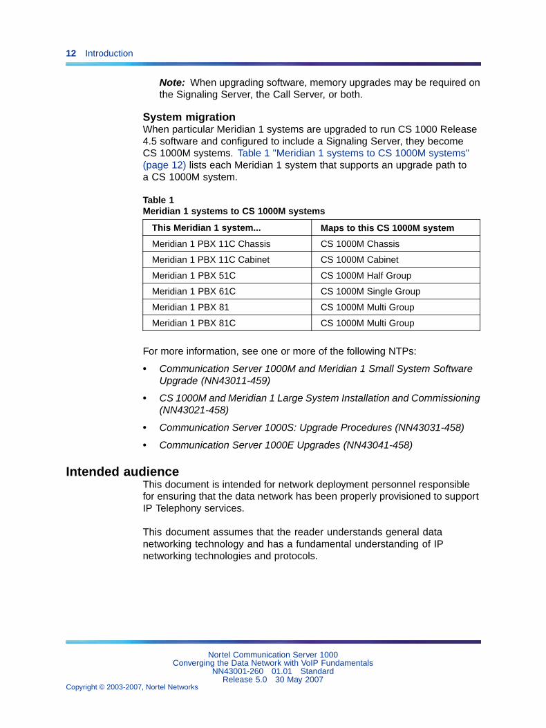
System migrationWhen particular Meridian 1 systems are upgraded to run CS 1000 Release4.5 software and configured to include a Signaling Server, they becomeCS 1000M systems. Table 1 "Meridian 1 systems to CS 1000M systems"(page 12) lists each Meridian 1 system that supports an upgrade path toa CS 1000M system.
Table 1Meridian 1 systems to CS 1000M systems
This Meridian 1 system... Maps to this CS 1000M system
Meridian 1 PBX 11C Chassis CS 1000M Chassis
Meridian 1 PBX 11C Cabinet CS 1000M Cabinet
Meridian 1 PBX 51C CS 1000M Half Group
Meridian 1 PBX 61C CS 1000M Single Group
Meridian 1 PBX 81 CS 1000M Multi Group
Meridian 1 PBX 81C CS 1000M Multi Group
For more information, see one or more of the following NTPs:
• Communication Server 1000M and Meridian 1 Small System SoftwareUpgrade (NN43011-459)
• CS 1000M and Meridian 1 Large System Installation and Commissioning(NN43021-458)
• Communication Server 1000S: Upgrade Procedures (NN43031-458)
• Communication Server 1000E Upgrades (NN43041-458)
Intended audienceThis document is intended for network deployment personnel responsiblefor ensuring that the data network has been properly provisioned to supportIP Telephony services.
This document assumes that the reader understands general datanetworking technology and has a fundamental understanding of IPnetworking technologies and protocols.
Nortel Communication Server 1000Converging the Data Network with VoIP Fundamentals
NN43001-260 01.01 StandardRelease 5.0 30 May 2007
Copyright © 2003-2007, Nortel Networks
.
Related information 13
ConventionsTerminologyIn this document, the following systems are referred to generically as"system":
• Communication Server 1000S (CS 1000S)
• Communication Server 1000M (CS 1000M)
• Communication Server 1000E (CS 1000E)
• Meridian 1
The following systems are referred to generically as "Small System":
• Communication Server 1000M Chassis (CS 1000M Chassis)
• Communication Server 1000M Cabinet (CS 1000M Cabinet)
• Meridian 1 PBX 11C Chassis
• Meridian 1 PBX 11C Cabinet
The following systems are referred to generically as "Large System":
• Communication Server 1000M Half Group (CS 1000M HG)
• Communication Server 1000M Single Group (CS 1000M SG)
• Communication Server 1000M Multi Group (CS 1000M MG)
• Meridian 1 PBX 51C
• Meridian 1 PBX 61C
• Meridian 1 PBX 81
• Meridian 1 PBX 81C
Related informationThis section lists information sources that relate to this document.
NTPsThe following NTPs are referenced in this document:
• Main Office Configuration for Survivable Remote Gateway 50 MainOffice Configuration for SRG200/400 Release 1.5 (NN43001-307)
• Signaling Server Installation and Commissioning (NN43001-312)
• IP Peer Networking Installation and Commissioning (NN43001-313)
• Branch Office Installation and Commissioning (NN43001-314)
• Telephony Manager3.1 Installation and Commissioning (NN43050-300)
• System Redundancy Fundamentals (NN43001-507)
Nortel Communication Server 1000Converging the Data Network with VoIP Fundamentals
NN43001-260 01.01 StandardRelease 5.0 30 May 2007
Copyright © 2003-2007, Nortel Networks
.
14 Introduction
• Software Input Output: Administration (NN43001-611)
• Emergency Services Access Fundamentals (NN43001-613)
• Telephony Manager 3.1 System Administration (NN43050-601)
• Element Manager System Reference - Administration (NN43001-632)
• Call Detail Recording Fundamentals (NN43001-550)
• IP Line Fundamentals (NN43100-500)
• IP Phones Fundamentals (NN43001-368)
• Software Input Output Reference - System Messages (NN43001-712)
• Traffic Measurement: Formats and Output Reference (NN43001-750)
• Software Input Output - Maintenance (NN43001-711)
• Communication Server 1000 Fault Management - SNMP (NN43001-719)
• Communication Server 1000M and Meridian 1 Large System Planningand Engineering (NN43021-220)
OnlineTo access Nortel documentation online, click the Technical Documentationlink under Support & Training on the Nortel home page:
www.nortel.com
CD-ROMTo obtain Nortel documentation on CD-ROM, contact your Nortel customerrepresentative.
Nortel Communication Server 1000Converging the Data Network with VoIP Fundamentals
NN43001-260 01.01 StandardRelease 5.0 30 May 2007
Copyright © 2003-2007, Nortel Networks
.
15
Overview
ContentsThis section contains information on the following topics:
"Introduction" (page 15)
"Network convergence" (page 17)
"Voice applications" (page 18)
"Network design" (page 19)
"Server LAN design" (page 19)
"Configuring the DHCP server" (page 20)
"Quality of Service" (page 20)
"QoS versus bandwidth" (page 20)
"Network performance measurement and monitoring" (page 21)
"Application requirements" (page 21)
"Available tools" (page 22)
"Achieving satisfactory voice quality" (page 22)
IntroductionThis NTP discusses a number of areas which you must address whenbuilding a converged multimedia network. These include:
• network design
• network performance
• Quality of Service (QoS)
• operations
Nortel Communication Server 1000Converging the Data Network with VoIP Fundamentals
NN43001-260 01.01 StandardRelease 5.0 30 May 2007
Copyright © 2003-2007, Nortel Networks
.
16 Overview
WARNINGBefore a CS 1000 system can be installed, a network assessmentmust be performed and the network must be VoIP-ready. See"Network design assessment" (page 25).
If the minimum VoIP network requirements are not met, the systemdoes not operate properly.
Many considerations are important when creating and maintaining aconverged network. It is important to gain a detailed understanding ofthe design of the existing data network before implementing a Voice overInternet Protocol (VoIP) network.
To create a VoIP-grade network, certain QoS standards for various basicnetwork elements must be met. Several QoS parameters can be configured,measured, and monitored to determine if the desired service levels areprovided and obtained. The mechanisms needed to design a robust,redundant QoS-managed VoIP network are described in this NTP.
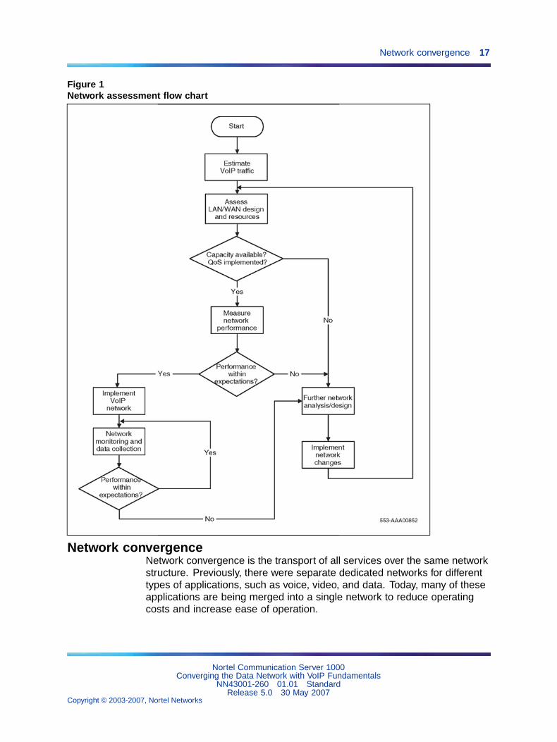
Figure 1 "Network assessment flow chart" (page 17) is a logical view of thesteps necessary to assess a network for Voice over Internet Protocol (VoIP)readiness. Use this network assessment flow chart as a guideline for thisNTP and the network engineering process.
Nortel Communication Server 1000Converging the Data Network with VoIP Fundamentals
NN43001-260 01.01 StandardRelease 5.0 30 May 2007
Copyright © 2003-2007, Nortel Networks
.
Network convergence 17
Figure 1Network assessment flow chart
Network convergenceNetwork convergence is the transport of all services over the same networkstructure. Previously, there were separate dedicated networks for differenttypes of applications, such as voice, video, and data. Today, many of theseapplications are being merged into a single network to reduce operatingcosts and increase ease of operation.
Nortel Communication Server 1000Converging the Data Network with VoIP Fundamentals
NN43001-260 01.01 StandardRelease 5.0 30 May 2007
Copyright © 2003-2007, Nortel Networks
.
18 Overview
A traditional enterprise can have the following network types:
• private Time Division Multiplexing (TDM)-based voice network
• IP network to the Internet
• Integrated Services Digital Network (ISDN) for video conferencing
• Systems Network Architecture (SNA) (an IBM computer networkarchitecture)
• multi-protocol network, including such varied protocol types asInternetwork Packet Exchange (IPX) and AppleTalk
Many enterprises look to converged networks to achieve cost andoperational efficiency. A converged network mixes different types of traffic,each with different requirements. This creates difficulties that must beaddressed. When different types of applications had their own dedicatednetworks, QoS technology played a smaller role. Dedicated network trafficwas similar in behavior, and the networks were fine-tuned to achieve therequired behavior of the applications.
For example, the expectation for interactive voice is low packet loss anda minimal, fixed amount of delay. Data is sent in a steady stream, withsamples transmitted at fixed time intervals. Such performance is obtainedon a circuit-switched network. A best-effort data network has varyingamounts of packet loss and variable delay usually caused by networkcongestion. A packet-based data network usually is the opposite of what isneeded by a voice application.
Implementing QoS mechanisms helps to address this issue.
Voice applicationsVoice applications originated on Public Switched Telephone Networks(PSTNs) and used circuit switching in the form of Time Division Multiplexing(TDM).
TDM has been engineered with very specific, predetermined behaviorsto support real-time voice conversations. On a TDM network, bandwidthis guaranteed to be available for any voice call, therefore voice trafficexperiences a low, fixed amount of delay, with essentially no loss.
IP networks do not guarantee that bandwidth will be available for voicecalls unless QoS mechanisms are used to restrict delay and data loss tomaintain acceptable user quality.
If a voice application is sent over a best-effort IP network (see page 22), thefollowing can occur:
• Voice packets experience variable, unpredictable amounts of delay.
• Voice packets are dropped when the network is congested.
Nortel Communication Server 1000Converging the Data Network with VoIP Fundamentals
NN43001-260 01.01 StandardRelease 5.0 30 May 2007
Copyright © 2003-2007, Nortel Networks
.
Network design 19
• Voice packets can be reordered by the network if the packets arriveout of sequence.
QoS techniques can be applied to properly-engineered networks to supportVoIP with acceptable, consistent, and predictable voice quality.
Network designIt is important to have a detailed understanding of the converged networkdesign. This can be done by answering the following questions:
• Is a physical network diagram available for the data and voice network?
— Is a logical diagram for both networks available? The logical diagramcan be provided by the SNMP Network Management System (NMS).
• What Local Area Network (LAN)/Wide Area Network (WAN) platformsare currently installed?
— Do the currently installed platforms support some form of QoS?
• What types of links are in use?
— Point-to-Point Protocol (PPP)
— Frame Relay (FR)
— Asynchronous Transfer Mode (ATM)
• What protocols are in use? What routing protocols are in use?
• What link speeds are in use on the LAN? What link speeds are in useon the WAN?
• What is the current utilization of those links?
— What are the peak delays on the WAN links?
— What is the current delay and packet loss?
• What is the current flow of data and voice traffic?
For more information, refer to "Network design assessment" (page 25).
Server LAN designServer LAN design for the system is discussed in "Server LAN design"(page 131). The topics covered include Layer 2 design, IP addressing,and server LAN redundancy.
Nortel Communication Server 1000Converging the Data Network with VoIP Fundamentals
NN43001-260 01.01 StandardRelease 5.0 30 May 2007
Copyright © 2003-2007, Nortel Networks
.
20 Overview
Configuring the DHCP serverIP Phones 200x support automatic configuration using the Dynamic HostConfiguration Protocol (DHCP). See "Configuration of the DHCP server"(page 173) for details on configuring the DHCP server.
Quality of ServiceIP networks are inherently "best-effort networks." They treat all packets inthe same manner. A best-effort network has no specified parameters. Itdoes not guarantee how fast data is transmitted over a network, and has noassurances that the data will even be delivered at all.
Therefore, a means of providing guarantees is required. The purposeof Quality of Service (QoS) mechanisms is to guarantee that the networktreats certain packets in a specified manner.
QoS mechanisms refer to packet tagging mechanisms and networkarchitecture decisions on the TCP/IP network to expedite packet forwardingand delivery.
QoS is especially important for low-speed links, where the usual amount ofbandwidth available is only several hundred kbps. For example, data trafficcould easily use all of the bandwidth available on a link, thereby causingvoice quality problems. QoS mechanisms can be used to guarantee thatnetwork bandwidth is available for voice traffic.
End-to-end QoS is required for IP Telephony applications to achieve goodvoice quality and is achieved by ensuring that the different parts of thenetwork apply consistent treatment to the telephony packets.
Many of the available QoS mechanisms are described in "QoS mechanisms"(page 41).
QoS versus bandwidthOne approach to network engineering says that QoS is not needed; simplyincreasing bandwidth provides enough QoS for all applications. This theoryalso states that implementing QoS is complicated; adding bandwidth iseasy. However, due to the bursty nature of IP network traffic, even very largeamounts of bandwidth may not be enough to prevent congestion during aburst of traffic at a particular instance in time.
If all networks had infinite bandwidth available so that network congestionnever occurred, QoS technology would not be needed. While havingadequate bandwidth provisioned on the network is very important, overprovisioning may not be very realistic; therefore, QoS mechanisms areneeded.
Nortel Communication Server 1000Converging the Data Network with VoIP Fundamentals
NN43001-260 01.01 StandardRelease 5.0 30 May 2007
Copyright © 2003-2007, Nortel Networks
.
Network performance measurement and monitoring 21
Network performance measurement and monitoringTCP/IP was originally designed to reliably send a packet to its destination.Little consideration was given to the length of time it took to get there.Today, IP networks transport data from many different application types.Many of these applications require minimal delay. Delay is the length oftime needed for information to travel through a network. Significant delaycan adversely affect end-user quality; and in some cases, the applicationdoes not function at all.
Networks now carry many different types of traffic. Each traffic type hasunique requirements for the following QoS parameters:
• availability
• bandwidth
• delay
• jitter
• packet loss
These QoS parameters can be measured and monitored to determine if theymeet desired service levels. Each of these elements are discussed in detailin "Network performance measurement" (page 83). "Operating the VoIPnetwork" (page 185) also discuss the ongoing monitoring, management,and measurement of the network.
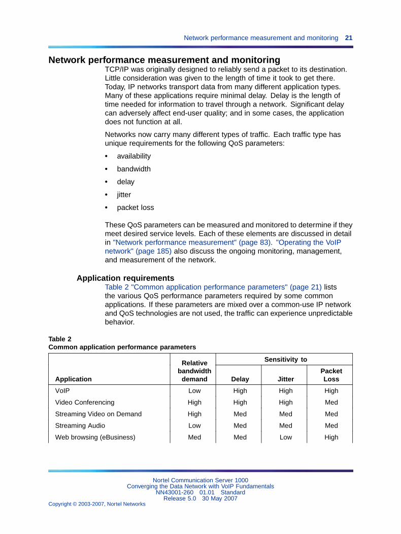
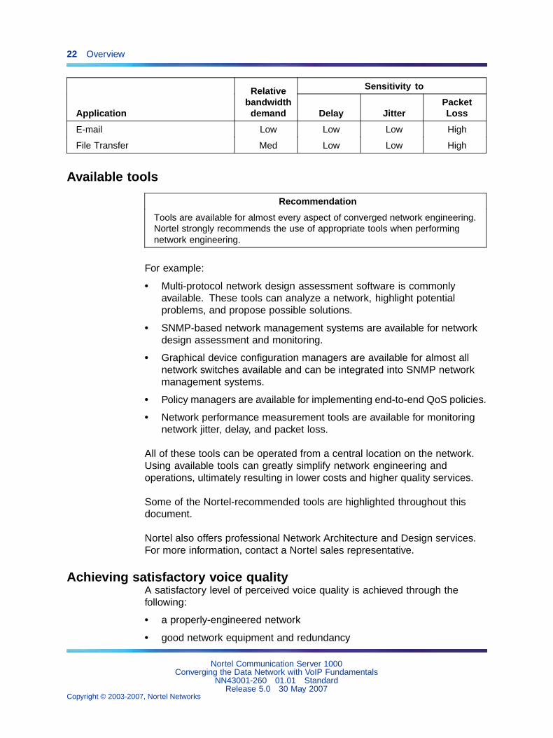
Application requirementsTable 2 "Common application performance parameters" (page 21) liststhe various QoS performance parameters required by some commonapplications. If these parameters are mixed over a common-use IP networkand QoS technologies are not used, the traffic can experience unpredictablebehavior.
Table 2Common application performance parameters
Sensitivity to
Application
Relativebandwidth
demand Delay JitterPacketLoss
VoIP Low High High High
Video Conferencing High High High Med
Streaming Video on Demand High Med Med Med
Streaming Audio Low Med Med Med
Web browsing (eBusiness) Med Med Low High
Nortel Communication Server 1000Converging the Data Network with VoIP Fundamentals
NN43001-260 01.01 StandardRelease 5.0 30 May 2007
Copyright © 2003-2007, Nortel Networks
.
22 Overview
Sensitivity to
Application
Relativebandwidth
demand Delay JitterPacketLoss
E-mail Low Low Low High
File Transfer Med Low Low High
Available tools
Recommendation
Tools are available for almost every aspect of converged network engineering.Nortel strongly recommends the use of appropriate tools when performingnetwork engineering.
For example:
• Multi-protocol network design assessment software is commonlyavailable. These tools can analyze a network, highlight potentialproblems, and propose possible solutions.
• SNMP-based network management systems are available for networkdesign assessment and monitoring.
• Graphical device configuration managers are available for almost allnetwork switches available and can be integrated into SNMP networkmanagement systems.
• Policy managers are available for implementing end-to-end QoS policies.
• Network performance measurement tools are available for monitoringnetwork jitter, delay, and packet loss.
All of these tools can be operated from a central location on the network.Using available tools can greatly simplify network engineering andoperations, ultimately resulting in lower costs and higher quality services.
Some of the Nortel-recommended tools are highlighted throughout thisdocument.
Nortel also offers professional Network Architecture and Design services.For more information, contact a Nortel sales representative.
Achieving satisfactory voice qualityA satisfactory level of perceived voice quality is achieved through thefollowing:
• a properly-engineered network
• good network equipment and redundancy
Nortel Communication Server 1000Converging the Data Network with VoIP Fundamentals
NN43001-260 01.01 StandardRelease 5.0 30 May 2007
Copyright © 2003-2007, Nortel Networks
.
Achieving satisfactory voice quality 23
• adequate bandwidth for peak usage
• use of QoS mechanisms
• ongoing monitoring and maintenance
If these elements are not present, VoIP performance suffers.
This document provides recommendations for the following:
• network design and configuration
• QoS mechanisms
• performance measurements
• operational monitoring and maintenance
Nortel Communication Server 1000Converging the Data Network with VoIP Fundamentals
NN43001-260 01.01 StandardRelease 5.0 30 May 2007
Copyright © 2003-2007, Nortel Networks
.

24 Overview
Nortel Communication Server 1000Converging the Data Network with VoIP Fundamentals
NN43001-260 01.01 StandardRelease 5.0 30 May 2007
Copyright © 2003-2007, Nortel Networks
.
25
Network design assessment
ContentsThis section contains information on the following topics:
"Introduction" (page 26)
"Network modeling" (page 26)
"Physical and logical network diagrams" (page 26)
"Sample IP network model" (page 27)
"LAN and WAN platforms" (page 30)
"Campus platforms" (page 30)
"Supported QoS mechanisms" (page 31)
"Bandwidth and data network switch efficiency" (page 31)
"Security and QoS" (page 32)
"Protocols in use" (page 32)
"Routing protocols" (page 32)
"Mixing protocols" (page 33)
"Link speeds" (page 33)
"Link types" (page 34)
"Point-to-point links (PPP)" (page 34)
"Frame Relay" (page 34)
Figure 5 "Large campus network example" (page 29)
"Virtual Private Network" (page 35)
"Link utilization assessment" (page 35)
"Assessing link utilization" (page 35)
"Traffic flows in the network" (page 37)
"Available traffic tools" (page 37)
"Service level agreements" (page 38)
"Summary" (page 39)
Nortel Communication Server 1000Converging the Data Network with VoIP Fundamentals
NN43001-260 01.01 StandardRelease 5.0 30 May 2007
Copyright © 2003-2007, Nortel Networks
.
26 Network design assessment
Introduction
WARNINGBefore a CS 1000 system can be installed, a network assessmentmust be performed and the network must be VoIP-ready.
If the minimum VoIP network requirements are not met, the systemdoes not operate properly.
It is important to gain a full understanding of the design of an existing datanetwork before implementing a VoIP network. This section describes keyissues to consider when creating a new converged voice and data network.
For example, it is very important to assess the network for such things as:
• the distribution of protocols in the network
• the level of QoS on the network
• the link speeds, link types, and link utilization
• the traffic flows in the network
Some of the tools used to assess the VoIP network are described, as wellas examples of logical connection diagrams for small, medium, and largecampus networks.
Network modelingNetwork analysis can be difficult or time-consuming if the intranet and theCS 1000 system installation are large. Commercial network modeling toolscan analyze "what-if" scenarios predicting the effect of topology, routing,and bandwidth changes to the network. These modeling tools work with anexisting network management system to load current configuration, traffic,and policies into the modeling tool. Network modeling tools can help toanalyze and test the recommendations given in this document to predicthow delay and error characteristics impact the network.
Physical and logical network diagramsTo determine VoIP readiness, diagrams of both the data and voiceinfrastructure (physical and logical) are required. These diagrams arevaluable when determining the platforms deployed in the network as wellas the logical design such as the IP addressing architecture, link speeds,and connectivity.
Note: Network diagrams are typically created using SNMP NetworkManagement Systems (NMS). NMS provides graphical views fromphysical connections between LANs and WANs to the logicalconnections of a Virtual LAN (VLAN).
Nortel Communication Server 1000Converging the Data Network with VoIP Fundamentals
NN43001-260 01.01 StandardRelease 5.0 30 May 2007
Copyright © 2003-2007, Nortel Networks
.
Network modeling 27
From a voice perspective, the numbering plan and Call Detail Record (CDR)help to determine calling patterns in a multi-site environment.
Knowledge of routing of circuit-switched trunking facilities helps to determineutilization and bandwidth requirements for a VoIP deployment.
Sample IP network modelThe CS 1000 and Meridian 1 systems are VoIP servers suited for typicalcampus network designs.
In most cases, the system is connected logically to the server layer, as theserver layer is engineered for high-availability and security.
Having a large amount of bandwidth available at the server level, though notrequired by the Call Server, also helps to ensure satisfactory VoIP QoS.
Nortel recommends QoS mechanisms for all layers to ensure that voicetraffic obtains a level of service greater than the level of service for thebest-effort data traffic.
Physical connectivity, VLANs, and subnets for the core server componentsare configured at the server layer, following existing server layer design andconforming to the core server configuration requirements.
Alternately, if campus-distributed Media Gateway systems are used,they are connected at the distribution layer. The core IP network canbe configured with multiple VLANs and subnets to meet the core serverconfiguration requirements.
The following are planned based on the access and distribution layers’configuration:
• VLANs
• subnets
• QoS mechanisms for the IP Phones such as DiffServ and 802.1Q
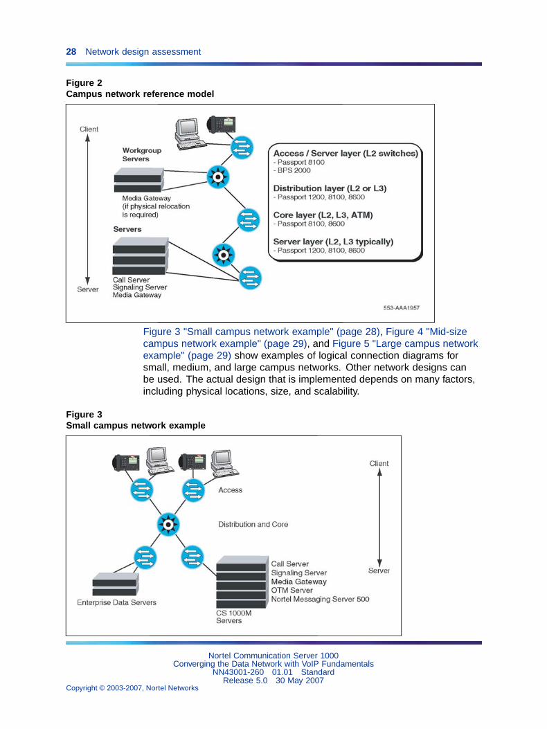
Typical network topologyFigure 2 "Campus network reference model" (page 28) provides a referencemodel for a campus network.
Nortel Communication Server 1000Converging the Data Network with VoIP Fundamentals
NN43001-260 01.01 StandardRelease 5.0 30 May 2007
Copyright © 2003-2007, Nortel Networks
.
28 Network design assessment
Figure 2Campus network reference model
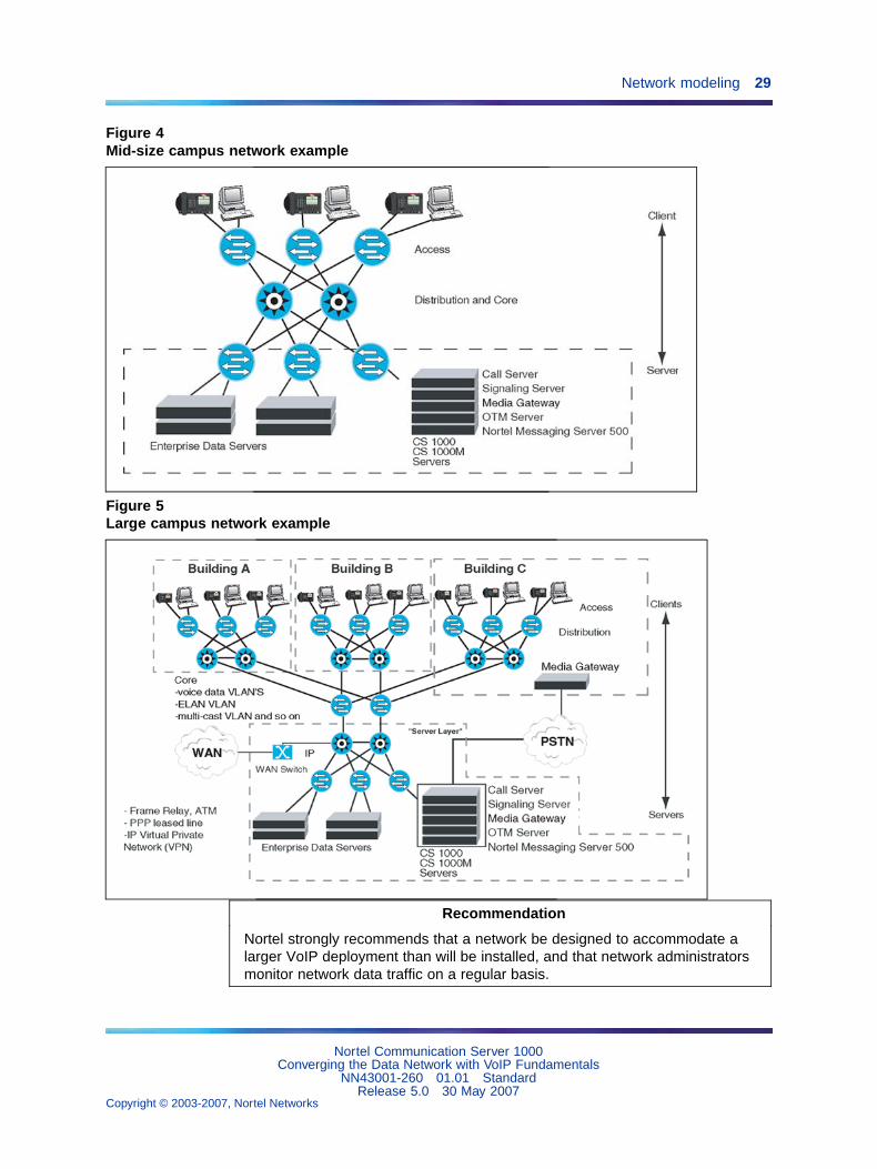
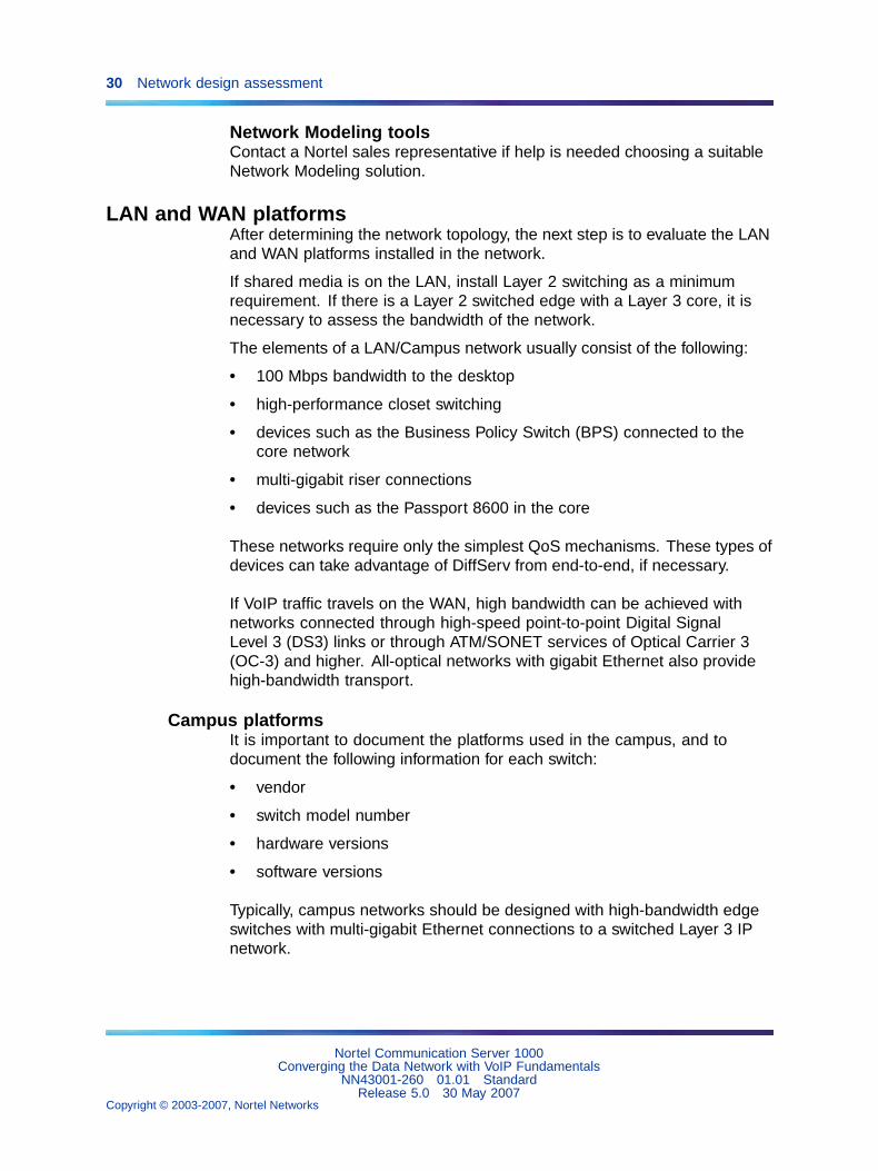
Figure 3 "Small campus network example" (page 28), Figure 4 "Mid-sizecampus network example" (page 29), and Figure 5 "Large campus networkexample" (page 29) show examples of logical connection diagrams forsmall, medium, and large campus networks. Other network designs canbe used. The actual design that is implemented depends on many factors,including physical locations, size, and scalability.
Figure 3Small campus network example
Nortel Communication Server 1000Converging the Data Network with VoIP Fundamentals
NN43001-260 01.01 StandardRelease 5.0 30 May 2007
Copyright © 2003-2007, Nortel Networks
.
Network modeling 29
Figure 4Mid-size campus network example
Figure 5Large campus network example
Recommendation
Nortel strongly recommends that a network be designed to accommodate alarger VoIP deployment than will be installed, and that network administratorsmonitor network data traffic on a regular basis.
Nortel Communication Server 1000Converging the Data Network with VoIP Fundamentals
NN43001-260 01.01 StandardRelease 5.0 30 May 2007
Copyright © 2003-2007, Nortel Networks
.
30 Network design assessment
Network Modeling toolsContact a Nortel sales representative if help is needed choosing a suitableNetwork Modeling solution.
LAN and WAN platformsAfter determining the network topology, the next step is to evaluate the LANand WAN platforms installed in the network.
If shared media is on the LAN, install Layer 2 switching as a minimumrequirement. If there is a Layer 2 switched edge with a Layer 3 core, it isnecessary to assess the bandwidth of the network.
The elements of a LAN/Campus network usually consist of the following:
• 100 Mbps bandwidth to the desktop
• high-performance closet switching
• devices such as the Business Policy Switch (BPS) connected to thecore network
• multi-gigabit riser connections
• devices such as the Passport 8600 in the core
These networks require only the simplest QoS mechanisms. These types ofdevices can take advantage of DiffServ from end-to-end, if necessary.
If VoIP traffic travels on the WAN, high bandwidth can be achieved withnetworks connected through high-speed point-to-point Digital SignalLevel 3 (DS3) links or through ATM/SONET services of Optical Carrier 3(OC-3) and higher. All-optical networks with gigabit Ethernet also providehigh-bandwidth transport.
Campus platformsIt is important to document the platforms used in the campus, and todocument the following information for each switch:
• vendor
• switch model number
• hardware versions
• software versions
Typically, campus networks should be designed with high-bandwidth edgeswitches with multi-gigabit Ethernet connections to a switched Layer 3 IPnetwork.
Nortel Communication Server 1000Converging the Data Network with VoIP Fundamentals
NN43001-260 01.01 StandardRelease 5.0 30 May 2007
Copyright © 2003-2007, Nortel Networks
.
LAN and WAN platforms 31
Riser access links and Layer 3 capacity are critical areas. If the desktopswitching platform provides 24 connections at 100 Mbps and has only four100 Mbps links, a significant bottleneck can occur at the riser. Serializationand queuing delays can become an issue that requires the application ofQoS mechanisms such as 802.1Q/802.1p and/or DiffServ.
Migrating 100 Mbps riser links to Gigabit Ethernet is suggested.
WARNINGAll VoIP servers and IP Phones must be connected to Layer 2switches.
Shared-media hubs are not supported.Shared-media hubs are low bandwidth devices and do not supportQoS mechanisms.
Supported QoS mechanismsTo ensure consistent voice quality, some form of QoS must be supportedon the platforms that transport VoIP. There are several ways to provideQoS, including the following:
• bandwidth management
• packet classification
• DiffServ
• fragmentation
• traffic shaping
• queuing mechanisms provided by the platform
If appropriate QoS mechanisms are not supported by the platform, anupgrade can be required.
Bandwidth and data network switch efficiencyIt is important to note the maximum packets per second forwarding ratesof the platforms. This determines the switch efficiency and the actualthroughput the platform is capable of supporting.
ExampleFor 64-Byte packets and a 10-Mbps link, the maximum forwarding rate is14 880 packets per second.
Bandwidth throughput is: (64 B / P) * (8 b / B) * (14,880 P / S) = 7.62 Mbps
A similar calculation is required for the WAN switches being used.
Nortel Communication Server 1000Converging the Data Network with VoIP Fundamentals
NN43001-260 01.01 StandardRelease 5.0 30 May 2007
Copyright © 2003-2007, Nortel Networks
.
32 Network design assessment
Note: Efficiency of an Ethernet switch is taken from the PerformanceSpecifications section of the Ethernet switch manual.
Security and QoSConsider the following security features:
• firewalls
• Network Address Translation (NAT) (See NAT)
• Secure Virtual Private Network (VPN) access through Secure InternetProtocol (IPSec) encryption. (See IPSec)
Routers might use NAT and IPSec for remote network users who connect tothe network through the public Internet, using IPSec encryption. A firewallconnection might also be in place. The network designer must considerthe security policy in force and see if the ports required for VoIP can gothrough the firewall.
Protocols in useWhen assessing the network for VoIP readiness, observe the distribution ofprotocols in the network, specifically on the WAN. Tools available for thistask includeNetwork Management Systems (NMS), which can poll devicesthrough SNMP probes, RMON probes, or both, and analyze the results.
Routing protocolsIt is important to note the routing protocols used within the network, asthey can affect network availability.
LAN protocolsRouting protocols in the LAN must be considered when implementing VoIP.
WAN protocolsRouting protocols in the WAN can be very important when considering howVoIP calls will be routed and how quickly fail-over occurs. When planninga VoIP network, be aware of what situations trigger a routing table updatewith respect to the routing protocol. This helps when predicting what path aVoIP flow might take during a failure in the network.
ConvergenceConvergence is the point where all internetworking devices have a commonunderstanding of the routing topology. The time it takes a network tore-converge after a link failure must be considered, as the process mighttake several minutes depending on the network size and routing protocol inuse.
Nortel Communication Server 1000Converging the Data Network with VoIP Fundamentals
NN43001-260 01.01 StandardRelease 5.0 30 May 2007
Copyright © 2003-2007, Nortel Networks
.
Link speeds 33
Mixing protocolsVoIP performance can be impacted if a network is using multiple protocolson any particular segment.
For example, even with fragmentation implemented, if there are protocolsin use other than IP, those protocols can maintain larger frame sizes. Thiscan introduce additional delay to the VoIP traffic.
It is important to be aware that certain applications running over IP can setthe frames with the "may fragment" bit to 1, which prevents fragmentation.As part of the overall assessment process, the network analysis on the LANcan determine if any applications have this bit setting.
Link speedsLink speeds in a WAN environment are usually low compared to a LAN.When considering VoIP in a WAN environment, link speeds are an importantconsideration, as speeds under 1 Mbps result in the serialization delay ofVoIP packets. This can impair deployment. When smaller VoIP packetstravel over a network that typically has packet sizes up to 1500 bytes, theselarger packets introduce variable delay (jitter) in the network. This impactsvoice quality.
To address delay on a WAN, implement the following:
• protocol prioritization
• traffic shaping (for Frame Relay)
• DiffServ
• fragmentation and interleaving (larger packet sizes incur higherserialization delays and introduce jitter into the VoIP stream)
Other vendor devices also have several mechanisms available.
If link speed and packet size are considered, the serialization delayintroduced can be predicted. See "Serialization delay" (page 109) for moreinformation.
Recommendation
Nortel strongly recommends beginning with an MTU size of 232 bytes for linksunder 1 Mbps, adjusting upwards as needed.
Some applications do not perform well with an adjusted MTU, so caution mustbe used when utilizing MTU.
Nortel Communication Server 1000Converging the Data Network with VoIP Fundamentals
NN43001-260 01.01 StandardRelease 5.0 30 May 2007
Copyright © 2003-2007, Nortel Networks
.
34 Network design assessment
Link typesIdentify and document the link types used in the network. A number ofdifferent link types are available in the network and each can have animpact on VoIP.
A typical campus network can have 100 Mbps of bandwidth going to thedesk, with multi-gigabit riser links. Since bandwidth is plentiful, peak linkutilization is the most important issue. If link utilization is averaged, it maynot be accurate. A minimum of Layer 2 switching is required, with no sharedmedia.
Point-to-point links (PPP)PPP links are direct point-to-point links, and give the network operatormaximum control over QoS. PPP links provide dedicated bandwidth andflexible termination points.
Frame RelayFrame Relay (FR) networks provide more flexibility when the requirementsinclude a full meshed topology. They have a lower overall cost, with respectto meshed designs.
Frame Relay networks are based on a shared-access model, where DataLink Connection Identifier (DLCI) numbers are used to define PermanentVirtual Circuits (PVCs) in the network.
QoS in a Frame Relay network is achieved by specifying a CommittedInformation Rate (CIR) and using separate PVC’s. CIR is the level of datatraffic (in bits) that the carrier agrees to handle, averaged over a periodof time.
The CIR on the voice traffic PVC must be set for the total peak traffic,because any traffic that exceeds the CIR is marked Discard Eligible (DE) andcan be dropped by the carrier. This is not an acceptable condition for VoIPtraffic, as real-time data carrying packetized voice cannot be retransmitted.
It is important to understand the design of the carrier network, how muchtraffic is currently being transported, and if any type of Service LevelAgreement (SLA), other than CIR, is offered.
The WAN-access platform in the network can help ensure that VoIP trafficdoes not exceed the CIR on the PVC. Protocol prioritization, traffic shapingand fragmentation can insure that the VoIP traffic is transmitted first anddoes not exceed the CIR on the PVC.
Nortel Communication Server 1000Converging the Data Network with VoIP Fundamentals
NN43001-260 01.01 StandardRelease 5.0 30 May 2007
Copyright © 2003-2007, Nortel Networks
.
Link utilization assessment 35
Asynchronous Transfer Mode (ATM)ATM transport can provide a Constant Bit Rate (CBR) service, dedicating achannel with a fixed bandwidth based on the application’s needs.
Using ATM as a transport for VoIP adds overhead associated with ATM. AG.711 CODEC with 20 ms voice payload, when the associated TCP, UDP,and RTP header information is added, can become a 200-byte frame.
Using ATM for transport requires the frame to be segmented to fit intomultiple cells. This adds an additional 10–15% of overhead. The G.729CODEC significantly reduces the frame size to 60 bytes, so CODECselection is crucial for the WAN.
Virtual Private NetworkA Virtual Private Network (VPN) is a network that uses the publictelecommunication infrastructure, such as the Internet, to provide remoteoffices or individual users with secure access to their organization’snetwork. Encryption and other security mechanisms are used to ensure thatonly authorized users can access the network and that the data cannotbe intercepted.
Link utilization assessmentTo support VoIP over WAN links, it is important to assess link utilization.There are several ways to gather statistical information on a WAN link. Toolssuch as an existing network management system should have the ability topoll routers through SNMP and collect the statistics over a period of timeon utilization of a given WAN link.
Other methods of assessment include the use of imbedded RemoteMonitoring (RMON) and external RMON probes installed for the purpose ofgathering statistical information, including link utilization.
Over low-bandwidth connections, the amount of VoIP traffic should belimited to a percentage of the bandwidth of the connection. This is done tominimize the maximum queuing delay that the VoIP traffic experiences overlow-bandwidth connections.
Assessing link utilizationWAN links are the highest repeating expenses in the network and they oftencause capacity problems in the network. Unlike LAN bandwidth, whichis virtually free and easily implemented, WAN links take time to finance,provision, and upgrade, especially inter-LATA (Local Access and TransportArea) and international links. For these reasons, it is important to determinethe state of WAN links in the intranet before installing the network.
Nortel Communication Server 1000Converging the Data Network with VoIP Fundamentals
NN43001-260 01.01 StandardRelease 5.0 30 May 2007
Copyright © 2003-2007, Nortel Networks
.
36 Network design assessment
ATTENTIONIMPORTANT!The use of QoS mechanisms which prioritize voice over data traffic effectivelyincreases the amount of bandwidth available to voice traffic.
To assess the link utilization, follow the steps in Procedure 1 "Assessing linkutilization" (page 36).
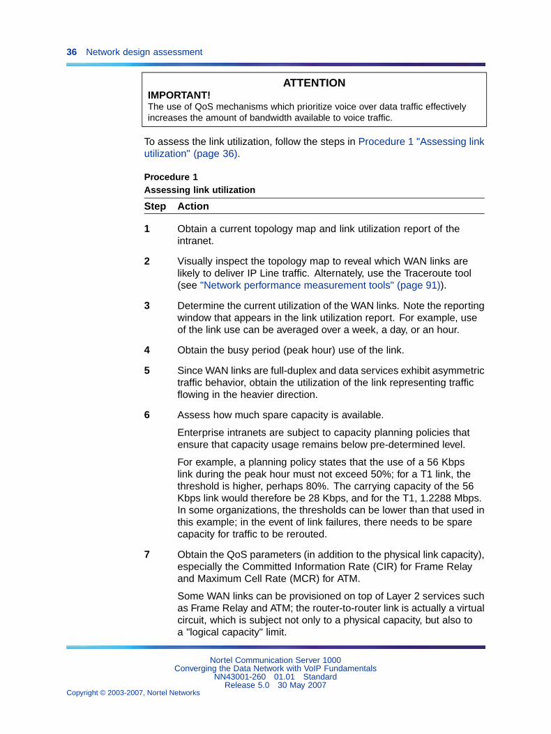
Procedure 1Assessing link utilization
Step Action
1 Obtain a current topology map and link utilization report of theintranet.
2 Visually inspect the topology map to reveal which WAN links arelikely to deliver IP Line traffic. Alternately, use the Traceroute tool(see "Network performance measurement tools" (page 91)).
3 Determine the current utilization of the WAN links. Note the reportingwindow that appears in the link utilization report. For example, useof the link use can be averaged over a week, a day, or an hour.
4 Obtain the busy period (peak hour) use of the link.
5 Since WAN links are full-duplex and data services exhibit asymmetrictraffic behavior, obtain the utilization of the link representing trafficflowing in the heavier direction.
6 Assess how much spare capacity is available.
Enterprise intranets are subject to capacity planning policies thatensure that capacity usage remains below pre-determined level.
For example, a planning policy states that the use of a 56 Kbpslink during the peak hour must not exceed 50%; for a T1 link, thethreshold is higher, perhaps 80%. The carrying capacity of the 56Kbps link would therefore be 28 Kbps, and for the T1, 1.2288 Mbps.In some organizations, the thresholds can be lower than that used inthis example; in the event of link failures, there needs to be sparecapacity for traffic to be rerouted.
7 Obtain the QoS parameters (in addition to the physical link capacity),especially the Committed Information Rate (CIR) for Frame Relayand Maximum Cell Rate (MCR) for ATM.
Some WAN links can be provisioned on top of Layer 2 services suchas Frame Relay and ATM; the router-to-router link is actually a virtualcircuit, which is subject not only to a physical capacity, but also toa "logical capacity" limit.
Nortel Communication Server 1000Converging the Data Network with VoIP Fundamentals
NN43001-260 01.01 StandardRelease 5.0 30 May 2007
Copyright © 2003-2007, Nortel Networks
.
Traffic flows in the network 37
8 The difference between the current capacity, and its allowable limit,is the available VoIP capacity.
For example, a T1 link used at 48% during the peak hour, with aplanning limit of 80%, has an available capacity of about 492 Kbps.
—End—
Traffic flows in the networkIdentify traffic flows in the network by using an existing Network ManagementSystem (NMS) or another passive tool, such as a packet sniffer. These toolsidentify protocol distribution in the network and traffic flow between devices.RMON probes and devices with embedded RMON capability can also helpthe network designer determine where traffic flows occur.
Assess traffic flows over a period of time (a week or longer depending onthe complexity of the network). Observe the peak times of the day, theweek, and the month to determine the highest utilization periods.
Once traffic flows are identified, determine bandwidth requirements usingtools such as a VoIP bandwidth calculator. Ask your Nortel representativefor the VoIP bandwidth calculator spreadsheet. For more information, see"VoIP Bandwidth Demand Calculator" (page 99).
Available traffic toolsThere are many tools available for assessing network traffic flows. Someof these include:
• Traceroute
• Call Detail Record
• Traffic study
• Network Diagnostic Utilities (refer to "Network Diagnostic Utilities" (page191))
TracerouteTraceroute uses the IP TTL (time-to-live) field to determine router hopsto a specific IP address. A router must not forward an IP packet with aTTL field of 0 or 1. It must instead throw away the packet and return tothe originating IP address an ICMP "time exceeded" message. Tracerouteuses this mechanism by sending an IP datagram with a TTL of 1 to thespecified destination host.
The first router to handle the datagram sends back a "time exceeded"message. This identifies the first router on the route. Then Traceroutesends out a datagram with a TTL of 2. This causes the second router on
Nortel Communication Server 1000Converging the Data Network with VoIP Fundamentals
NN43001-260 01.01 StandardRelease 5.0 30 May 2007
Copyright © 2003-2007, Nortel Networks
.
38 Network design assessment
the route to return a "time exceeded" message and so on until all hopshave been identified. The Traceroute IP datagram has a UDP Port numberunlikely to be in use at the destination (usually > 30 000). This causes thedestination to return a "port unreachable" ICMP packet, thereby identifyingthe destination host.
Traceroute can be used to measure roundtrip times to all hops along aroute, thereby identifying bottlenecks in the network.
Call Detail RecordObtain a Call Detail Record (CDR) to locate the VoIP traffic flows in thenetwork. The CDR can help identify the network routes that VoIP will use.
The peak values for time of day, day of week, and day of month must beconsidered to ensure consistent voice quality.
For more information, refer to Call Detail Recording Fundamentals(NN43001-550).
Traffic studyTraffic is a measurement of a specific resource’s activity level. LD 02 hasbeen reserved for scheduling and selecting the traffic study options.
A network traffic study provides information such as:
• the amount of call traffic on each choice in each route list
• the number of calls going out on expensive routes in each route list
• queuing activity (Off-Hook Queuing and Callback Queuing) and thelength of time users queue, on average
For more information on traffic studies, refer to:
• Traffic Measurement: Formats and Output Reference (NN43001-750)
• LD 02 in Software Input Output: Administration (NN43001-611)
Service level agreementsAs part of their service level agreement, the service provider shouldguarantee a certain amount of bandwidth.
Whether a home user on a cable or DSL connection, or a large networkcustomer using Frame Relay, the service provide must guarantee bandwidthfor VoIP.
Nortel Communication Server 1000Converging the Data Network with VoIP Fundamentals
NN43001-260 01.01 StandardRelease 5.0 30 May 2007
Copyright © 2003-2007, Nortel Networks
.
Summary 39
Guaranteed bandwidth in Frame Relay, for example, is known as CommittedInformation Rate (CIR). The guaranteed bandwidth must be sufficient toaccommodate all of the network traffic. Ensure that the CIR rate that wascontracted is received when leasing a connection.
Exercise caution if service level agreements are not available.
SummaryIt is crucial to fully understand the existing data network design beforeimplementing a VoIP network. There are many considerations that areimportant when creating a new converged voice and data network. Networkdesign tools are available to assist with this process.
Nortel Communication Server 1000Converging the Data Network with VoIP Fundamentals
NN43001-260 01.01 StandardRelease 5.0 30 May 2007
Copyright © 2003-2007, Nortel Networks
.

40 Network design assessment
Nortel Communication Server 1000Converging the Data Network with VoIP Fundamentals
NN43001-260 01.01 StandardRelease 5.0 30 May 2007
Copyright © 2003-2007, Nortel Networks
.
41
QoS mechanisms
ContentsThis section contains information on the following topics:
"Introduction" (page 42)
"Traffic mix" (page 43)
"TCP traffic behavior" (page 44)
"QoS problem locations" (page 44)
"Campus networks" (page 45)
"Wide Area Networks" (page 46)
"The QoS process" (page 46)
"Classification" (page 46)
"Marking" (page 47)
"Queuing" (page 47)
"WAN QoS mechanisms" (page 49)
"Bandwidth demand" (page 49)
"Fragmentation and interleaving" (page 50)
"Traffic Shaping" (page 53)
"RTP header compression" (page 55)
"PPP QoS" (page 55)
"Frame Relay QoS" (page 55)
"ATM QoS" (page 55)
"Layer 2 (Ethernet) QoS" (page 56)
"MAC address" (page 56)
"IEEE 802.1Q" (page 56)
"Port prioritization" (page 59)
"Layer 3 QoS" (page 61)
"IP address classification" (page 61)
Nortel Communication Server 1000Converging the Data Network with VoIP Fundamentals
NN43001-260 01.01 StandardRelease 5.0 30 May 2007
Copyright © 2003-2007, Nortel Networks
.
42 QoS mechanisms
"DiffServ for VoIP" (page 61)
"Trust configuration" (page 63)
"Voice signaling and media DSCPs" (page 64)
"Setting DSCP values" (page 64)
"TM and Element Manager QoS configuration" (page 66)
"Layer 4 (TCP/IP) classification" (page 68)
"Port number classification" (page 68)
"Protocol ID classification" (page 69)
"CS 1000 and Meridian 1 ports" (page 69)
"Policy management" (page 69)
"Optivity Policy Services" (page 69)
"Bandwidth Management" (page 69)
"VoIP bandwidth management zones" (page 71)
"Interzone vs. Intrazone" (page 73)
"Bandwidth Management is nodal" (page 74)
"VPNI and Zone numbers" (page 74)
"Relationship between zones and subnets" (page 75)
"Adaptive Bandwidth Management" (page 76)
"CODEC selection" (page 76)
"VoIP network voice engineering considerations" (page 77)
IntroductionThis section describes the mechanisms required to design a QoS-managedVoIP network with satisfactory voice quality.
Today’s corporate intranets evolved to support data services that founda "best effort" IP delivery mechanism sufficient. Standard intranets aredesigned to support a set of QoS objectives dictated by these data services.
An IP network must be properly engineered and provisioned to achieve highvoice quality performance. The network administrator should implementQoS policies network-wide so voice packets receive consistent and propertreatment as they travel the network.
IP networks that treat all packets the same are called "best-effort networks".In such a network, traffic can experience different amounts of delay, jitter,and loss at any given time. This can produce the following problems:
• speech breakup
• speech clipping
• pops and clicks
Nortel Communication Server 1000Converging the Data Network with VoIP Fundamentals
NN43001-260 01.01 StandardRelease 5.0 30 May 2007
Copyright © 2003-2007, Nortel Networks
.
Introduction 43
• echo
A best-effort network does not guarantee bandwidth at any given time.
The best way to guarantee bandwidth for voice applications is to use QoSmechanisms in the intranet when the intranet is carrying mixed traffic types.
QoS mechanisms ensure bandwidth is 100% available at most times,maintaining consistent, acceptable levels of loss, delay, and jitter, evenunder heavy traffic loads.
QoS mechanisms are extremely important to ensure satisfactory voicequality. If QoS mechanisms are not used, there is no guarantee that thebandwidth required for voice traffic will be available. For example, a datafile downloaded from the intranet could use most of the WAN bandwidthunless voice traffic has been configured to have higher priority. If the datafile download could use most of the available bandwidth, this would causevoice packet loss, and therefore poor voice quality.
Recommendation
Nortel strongly recommends implementing suitable QoS mechanisms on any IPnetwork carrying VoIP traffic.
This section describes QoS mechanisms that work in conjunction with theCS 1000 node. This section also discusses the intranet-wide consequencesif the mechanisms are implemented.
Apply QoS mechanisms to the following VoIP media and signaling paths:
• TLAN connections
• VoIP traffic between IP Phones
• VoIP traffic between IP Phones and Voice Gateway Media Cards onthe TLAN subnet
Traffic mixBefore implementing QoS mechanisms in the network, assess the trafficmix of the network. QoS mechanisms depend on the process and ability todistinguish traffic by class to provide differentiated services.
If an intranet is designed to deliver only VoIP traffic, and all traffic flows areof equal priority, then there is no need to consider QoS mechanisms. Thisnetwork would only have one class of traffic.
In most corporate environments, the intranet primarily supports dataservices. When planning to offer voice services over the intranet, assessthe following:
• Are there existing QoS mechanisms? What are they? VoIP traffic shouldtake advantage of established mechanisms if possible.
Nortel Communication Server 1000Converging the Data Network with VoIP Fundamentals
NN43001-260 01.01 StandardRelease 5.0 30 May 2007
Copyright © 2003-2007, Nortel Networks
.
44 QoS mechanisms
• What is the traffic mix? If the volume of VoIP traffic is small compared todata traffic on the intranet, then IP QoS mechanisms will be sufficient. IfVoIP traffic is significant, data services might be impacted when thosemechanisms are biased toward VoIP traffic.
TCP traffic behaviorThe majority of corporate intranet traffic is TCP-based. Unlike UDP whichhas no flow control, TCP uses a sliding window flow control mechanism.Under this scheme, TCP increases its window size, increasing throughput,until congestion occurs. Congestion is detected by packet losses, and whenthat happens throughput quickly throttles down, and the whole cycle repeats.When multiple TCP sessions flow over few bottleneck links in the intranet,the flow control algorithm can cause TCP sessions in the network to throttleat the same time, resulting in a periodic and synchronized surge and ebb intraffic flows. WAN links appear to be congested at one period of time andthen are followed by a period of under-utilization. Two consequences are:
• WAN link inefficiency.
• VoIP traffic streams are unfairly affected.
The solution to this problem is Weighted Random Early Detection queueing(WRED) as described on "Weighted Random Early Detection (WRED)"(page 47).
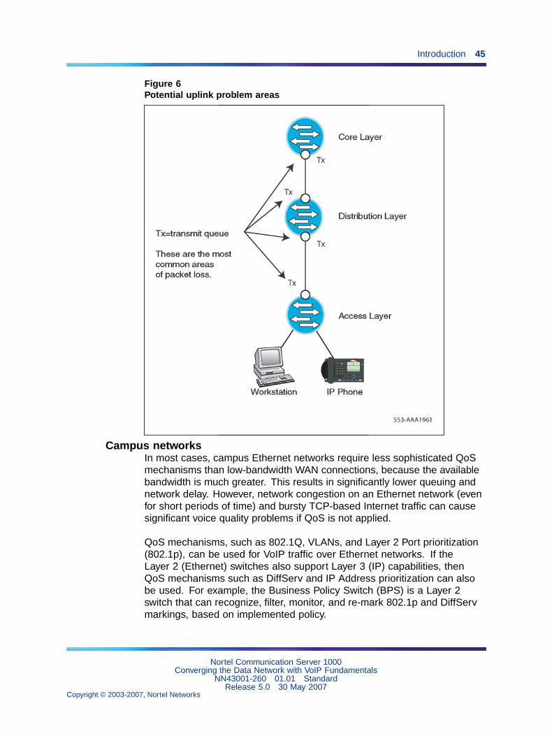
QoS problem locationsFigure 6 "Potential uplink problem areas" (page 45) identifies typicalnetwork congestion areas. Voice traffic competes for limited bandwidth onthe uplinks. These uplinks are shown in Figure 6 "Potential uplink problemareas" (page 45). Congestion at these points causes the majority of allpacket loss, delay, and jitter. QoS mechanisms can alleviate this congestionby using multiple queues with different priorities.
Nortel Communication Server 1000Converging the Data Network with VoIP Fundamentals
NN43001-260 01.01 StandardRelease 5.0 30 May 2007
Copyright © 2003-2007, Nortel Networks
.
Introduction 45
Figure 6Potential uplink problem areas
Campus networksIn most cases, campus Ethernet networks require less sophisticated QoSmechanisms than low-bandwidth WAN connections, because the availablebandwidth is much greater. This results in significantly lower queuing andnetwork delay. However, network congestion on an Ethernet network (evenfor short periods of time) and bursty TCP-based Internet traffic can causesignificant voice quality problems if QoS is not applied.
QoS mechanisms, such as 802.1Q, VLANs, and Layer 2 Port prioritization(802.1p), can be used for VoIP traffic over Ethernet networks. If theLayer 2 (Ethernet) switches also support Layer 3 (IP) capabilities, thenQoS mechanisms such as DiffServ and IP Address prioritization can alsobe used. For example, the Business Policy Switch (BPS) is a Layer 2switch that can recognize, filter, monitor, and re-mark 802.1p and DiffServmarkings, based on implemented policy.
Nortel Communication Server 1000Converging the Data Network with VoIP Fundamentals
NN43001-260 01.01 StandardRelease 5.0 30 May 2007
Copyright © 2003-2007, Nortel Networks
.
46 QoS mechanisms
Wide Area NetworksA Wide Area Network (WAN) is a geographically-dispersedtelecommunications network. For example, a WAN can extend across manycities or countries.
WANs require more sophisticated QoS mechanisms such as:
• fragmentation
• interleaving
• ATM
• Frame Relay
For more information, refer to "WAN QoS mechanisms" (page 49).
The QoS processPacket handling on a QoS-enabled network consists of three stages:
1. Classification
2. Marking
3. Queueing, also known as Forwarding
To implement QoS on an IP network, all packets entering the IP networkmust be classified and marked. The packets are then placed intotransmission queues of a certain priority.
Packets in high priority queues are transmitted before packets in best-effortlower priority queues. This means that VoIP packets no longer have tocompete with best-effort data packets for IP network resources. Typical QoSimplementations protect call quality by minimizing loss, delay, and jitter.Bandwidth cannot be assured without the use of some type of reservationprotocol, such as Resource Reservation Protocol (RSVP).
ClassificationSoftware on the following hardware elements can classify and mark VoIPpackets:
• Signaling Server - classifies its packets as signaling packets
• Voice Gateway Media Card - classifies its packets as voice or signalingpackets
• IP Phones - classify their packets as voice or signaling packets
Note: To classify Signaling Server and Voice Gateway Media Cardpackets at Layer 2 (802.1p) and/or Layer 3 (DiffServ), implement QoSmechanisms on the Signaling Server and Voice Gateway Media Cardand the Layer 2 switch ports to which they are attached. IP Phones with
Nortel Communication Server 1000Converging the Data Network with VoIP Fundamentals
NN43001-260 01.01 StandardRelease 5.0 30 May 2007
Copyright © 2003-2007, Nortel Networks
.
The QoS process 47
firmware 1.31 (or later) can classify voice and signaling packets at Layer2 (802.1p) and/or Layer 3 (DiffServ).
Classification can be implemented on Layer 2 or Layer 3 switches. Refer tothe switch’s documentation for information on configuring classification.
Policy management also provides other methods of classifying andmarking packets, based on identifiers such as the originating IP addressof the packet. For more information on Policy Management, see "Policymanagement" (page 69).
Packets can also be pre-marked with default 802.1p and DiffServ CodePoint(DSCP) values. Configure the Layer 2/Layer 3/Policy switches to trust thatthese packets are marked correctly.
MarkingWhen powered-up, Nortel IP Phones contact the Terminal Proxy Server(TPS) that controls them. The TPS then instructs the IP Phones to markall packets with a default, yet configurable (through CS 1000 Manager)DSCP and/or 802.1Q/802.1p tag. The tag is also configurable using CS1000 Element Manager.
• The control packets are marked for each of the following:
• Signaling Server
• Voice Gateway Media Cards
• Media Gateway 1000T (MG 1000T)
• Network Routing Service
QueuingQueueing delay is a major contributor to delay, especially on highly-utilizedand low-bandwidth WAN links (see "Queuing delay" (page 111)). Routersthat are QoS-aware and that support priority queuing can help reducethe queueing delay of voice packets when these packets are treated withpreference over other packets.
Weighted Random Early Detection (WRED)The global synchronization situation described in "TCP traffic behavior"(page 44) can be countered using a buffer management scheme thatdiscards packets randomly as the queue starts to exceed a threshold.Weighted Random Early Detection (WRED), an implementation of thisstrategy, also inspects the DiffServ bits in the IP header when consideringwhich packets to drop during buffer build up. In an intranet environmentwhere TCP traffic dominates real-time traffic, WRED can be used tomaximize the dropping of packets from long-lived TCP sessions andminimize the dropping of voice packets. Check the configuration guidelines
Nortel Communication Server 1000Converging the Data Network with VoIP Fundamentals
NN43001-260 01.01 StandardRelease 5.0 30 May 2007
Copyright © 2003-2007, Nortel Networks
.
48 QoS mechanisms
with the router vendor for performance ramifications when enabling WRED.If global synchronization is to be countered effectively, implement WRED atcore and edge routers.
Packet prioritization and schedulers for VoIPAll VoIP packets must be given a priority higher than the priority of non-voicepackets to minimize delay, jitter (delay variation), and packet loss whichadversely affect voice quality.
Note: All voice packets must be placed in the highest priority queueusing a strict-priority scheduler, or a scheduler that can be configuredto behave as a strict-priority scheduler. Some switches only permitnetwork-controlled traffic in the highest priority queue, leaving thesecond highest priority queue for the remaining user traffic.
Recommendation
Nortel strongly recommends that voice traffic be placed in a queue separatefrom other traffic types. However, if there are few queues available in the Layer2 or Layer 3 switch, then voice traffic can be combined with other high-prioritynetwork-controlled traffic. Because the queuing delay is small for Ethernetnetwork interfaces, this should have very little impact on voice quality.
Most Layer 2 switches use a strict-priority scheduler. A strict-priorityscheduler schedules all packets in a higher-priority queue before servicingany packets in a lower priority queue.
All VoIP packets must be queued in a router or switch using a strict priorityscheduler. This ensures that VoIP packets receive priority treatment over allother packets. Because a strict priority scheduler can "starve" the servicingof all other traffic queues, a threshold must be set to limit the maximumamount of bandwidth that the VoIP traffic can consume. This thresholdis also called "rate limiting".
Recommendation
Nortel strongly recommends that a strict priority scheduler be used for VoIP.
The Business Policy Switch (BPS) places the voice packets in the highestpriority queue using a strict-priority scheduler in its 4-queue system, whenQoS is enabled on an interface.
Note: Other vendors often refer to "priority queueing" when describingtheir techniques for strict-priority scheduling.
Nortel Communication Server 1000Converging the Data Network with VoIP Fundamentals
NN43001-260 01.01 StandardRelease 5.0 30 May 2007
Copyright © 2003-2007, Nortel Networks
.
WAN QoS mechanisms 49
Some Layer 3 switches and routers support priority and weightedschedulers. Voice packets must be placed in a queue that uses astrict-priority scheduler, or in a queue that uses a weighted schedulerconfigured to behave like a strict-priority scheduler.
The Passport 8600 uses a weighted scheduler, with its highest priority userqueue configured by default to behave like a strict-priority scheduler. Thequeue is configured with all Packet Transmit Opportunities (PTOs) enabled.This is equivalent to a weight of 100% (highest priority). Voice packets withDSCPs marked with ’EF’ (Expedited forwarding) and ’CS5’ (Class Selector5) are placed in this queue by default when QoS is enabled on an interface.
Nortel does not recommend other weighted schedulers, such as WeightedRound Robin (WRR) or Weighted Fair Queuing (WFQ). If the router orswitch does not support a priority scheduler and only supports a weightedscheduler, then the queue weight for VoIP traffic should be configuredto 100%. If a 100% weight cannot be configured due to some productlimitation, then consider replacing the product, because it can causeunpredictable voice quality.
WAN QoS mechanismsThere are many things to consider when using routers with low-bandwidthWANs and low bandwidth access network connections such as T1, xDSL,or Packet Cable.
This section specifically discusses WAN connections, but the techniquesand recommendations described also apply to low-bandwidth accessnetwork connections.
Bandwidth demandOne of the main attractions of VoIP is the ability to use an existing WAN datanetwork to save on inter-office toll calls. However, offices often connect overlow-bandwidth WAN connections, so special considerations must be madewhen adding VoIP over a bandwidth-limited connection.
When VoIP calls are active, routers configured with QoS (which prioritizesvoice traffic over data traffic) reduce the data traffic throughput by theamount of bandwidth being used for the VoIP call. This reduces the datatraffic throughput to a possibly unacceptable level. Adding VoIP to theexisting WAN data network might require an increase in the WAN bandwidth.
VoIP bandwidth is dependent on the following:
• type of CODEC used
• Voice Activity Detection (VAD), if used; also known as SilenceSuppression
• packetization rate (voice sample size)
Nortel Communication Server 1000Converging the Data Network with VoIP Fundamentals
NN43001-260 01.01 StandardRelease 5.0 30 May 2007
Copyright © 2003-2007, Nortel Networks
.
50 QoS mechanisms
• IP/UDP/RTP encapsulations
• RTP Header Compression, if used
• Layer 2 (link layer) protocol overhead for the specific link the voice trafficis traversing. Depending on the link protocol used and the optionsinvoked, the link protocol adds the following to each VoIP packet:
— 5 to 6 octets (FR)
— 7 to 8 octets (PPP)
— 18/22-26/30-38/42 octets (802.3 LAN – with or without802.1Q/802.1p 8-octet preamble and 12-octet interframe gap)
The extra octets create an additional overhead of 2 kbps (5-octet FR) to16.8 kbps (42-octet 802.3 LAN) for each VoIP call.
Note: ATM has its own overhead requirements. Due to the fixed cellsize of 53 octets, the additional overhead varies widely, dependingon the CODEC and packetization rate used.
Bandwidth exampleA company has two sites connected by a leased-line WAN connection (PPP)operating at 128 kbps. Due to the potential use of 20% of link capacity for"zero-bit stuffing", a safe assumption for link capacity is 102 kbps. For designpurposes, assume a maximum utilization of 70% (in this example, 90 kbps).
This bandwidth has been sufficient for the current data requirements. Thecompany believes that it only needs 70-80 kbps most of the time, withoccasional traffic peaks up to the full capacity. The company wants tosupport up to 4 simultaneous voice calls over the IP WAN network betweenthe sites.
If all 4 calls were simultaneously active, this would require 108.8 kbps (usinga G.729 CODEC, 20 ms voice sample, and PPP overhead/frame) of theavailable 90 kbps of the 128 kbps link.
This requirement exceeds the carrying capacity of the link and completelystarves that data traffic. The solution is to upgrade the WAN connectionbandwidth. A 256 kbps link is the minimum speed to provide 109 kbps forfour G.729 VoIP calls, 80 kbps for data, and 20% availability for zero-bitstuffing.
Fragmentation and interleavingTo minimize voice delay and jitter in mixed voice/data IP networks, fragmentlarge packets before they traverse limited-bandwidth (<1 Mbps) connections.There are several different protocols that can be used to fragment packets.
Nortel Communication Server 1000Converging the Data Network with VoIP Fundamentals
NN43001-260 01.01 StandardRelease 5.0 30 May 2007
Copyright © 2003-2007, Nortel Networks
.
WAN QoS mechanisms 51
For Frame Relay connections, the FRF.12 standard can be used forfragmenting packets. ATM provides fragmentation since all packets arefragmented into 53-byte ATM cells. Both of these fragmentation techniquesare acceptable.
Two types of fragmentation are more universal and not limited to a specificlink-layer technology, such as ATM or Frame Relay. These methods arePPP fragmentation and IP fragmentation.
Refer to the router’s documentation for information on configuring PPPand IP fragmentation.
Layer 2 fragmentation (ATM, FRF.12, PPP) is preferred over Layer 3fragmentation, as Layer 2 fragmentation universally affects all higher layerprotocols. Layer 3 fragmentation is less desirable for two reasons:
1. Layer 3 fragmentation applies only to the specific protocol being used.For example, Internet Protocol’s Maximum Transmission Unit (MTU,in bytes) affects only IP traffic. It has no effect on IPX, AppleTalk, orother protocols.
2. Some applications do not function because they set the "Do notFragment" bit. This prevents the application’s packets from beingtransmitted.
PPP fragmentation and interleavingMany routers support PPP fragmentation. PPP fragmentation splits largepackets into multiple smaller packets and encapsulates them into PPPframes before they are queued and transmitted. PPP fragmentation enableshigher-priority VoIP packets to be transmitted ahead of the lower-prioritydata packet fragments that have already been queued. The voice packetsand data fragments are interleaved so the maximum delay a voice packetwill experience is one fragment time (ideally <=10 ms), rather than onelarge packet time.
For example, a small voice packet enters a router, followed by a large datapacket, which is followed by a second voice packet. The first voice packetis transmitted as the first frame on the link. Next, the first data fragment istransmitted, followed by the second voice packet, then the second datafragment. If no more packets enter the router for a time, then the remainingdata fragments will continue to be transmitted until the entire data packethas been sent.
Interleaving is a result of voice packets having a higher priority thandata packets. A data fragment can be transmitted first; however, when ahigh-priority voice packet arrives, the voice packet will be sent before therest of the data packet.
Nortel Communication Server 1000Converging the Data Network with VoIP Fundamentals
NN43001-260 01.01 StandardRelease 5.0 30 May 2007
Copyright © 2003-2007, Nortel Networks
.
52 QoS mechanisms
IP fragmentationAll routers support IP fragmentation. IP fragmentation configures all IPpackets to a size determined by the MTU (Maximum Transmission Unit).Most routers use a default maximum packet size of 1500 bytes (the largestpacket allowed on Ethernet LANs), which can take a considerable amountof time to transmit over a low-bandwidth connection.
CAUTIONWhen determining the fragment size for a packet, ensure that thefragment size is not smaller than the voice packet. Fragment onlythe larger data packets, not the voice packets.
For example, over a 64 kbps link, a 1500-byte data packet takes 188 ms totransmit. If the WAN connection is Frame Relay (FR), this same queuingdelay is added again when the packet is queued at the far-end FR switch onthe other side of the connection. To achieve high voice quality, the desirableend-to-end delay for a voice packet is less than 150 ms. In this example,the data packet uses up almost the entire delay budget for the voice trafficbefore the first voice packet is ever transmitted. Jitter of 188 ms is created,which greatly exceeds the normal jitter buffer settings of 2 to 3 voice samplesizes (40 – 90 ms). This results in at least one packet, and usually manypackets, arriving too late to be used.
Over bandwidth-limited connections (<1 Mbps), if Layer 2 (ATM, FRF.12, orPPP) fragmentation is not used, the router must be configured to transmitsmaller packets by adjusting the MTU size for the IP packets. Ideally, theMTU size is adjusted to achieve an optimum delay of 10 ms or less over thedifferent connection speeds. Therefore, a higher bandwidth connection willhave a larger MTU size than a lower bandwidth connection.
Note: When IP fragmentation is used, the packets remain fragmentedfrom source to destination. This can result in reduced data performancesince the larger data packets are fragmented into multiple, smallerfragments that use more bandwidth.
Table 3 "Recommended MTU sizes for various connection speeds"(page 53) provides the recommended maximum MTU sizes for differentconnection speeds when using IP fragmentation. These choices result ina maximum delay of 8 ms.
Nortel Communication Server 1000Converging the Data Network with VoIP Fundamentals
NN43001-260 01.01 StandardRelease 5.0 30 May 2007
Copyright © 2003-2007, Nortel Networks
.
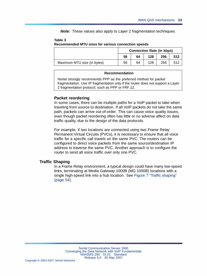
WAN QoS mechanisms 53
Note: These values also apply to Layer 2 fragmentation techniques
Table 3Recommended MTU sizes for various connection speeds
Connection Rate (in kbps)
56 64 128 256 512
Maximum MTU size (in bytes) 56 64 128 256 512
Recommendation
Nortel strongly recommends PPP as the preferred method for packetfragmentation. Use IP fragmentation only if the router does not support a Layer2 fragmentation protocol, such as PPP or FRF.12.
Packet reorderingIn some cases, there can be multiple paths for a VoIP packet to take whentraveling from source to destination. If all VoIP packets do not take the samepath, packets can arrive out-of-order. This can cause voice quality issues,even though packet reordering often has little or no adverse affect on datatraffic quality, due to the design of the data protocols.
For example, if two locations are connected using two Frame RelayPermanent Virtual Circuits (PVCs), it is necessary to ensure that all voicetraffic for a specific call travels on the same PVC. The routers can beconfigured to direct voice packets from the same source/destination IPaddress to traverse the same PVC. Another approach is to configure therouter to send all voice traffic over only one PVC.
Traffic ShapingIn a Frame Relay environment, a typical design could have many low-speedlinks, terminating at Media Gateway 1000B (MG 1000B) locations with asingle high-speed link into a hub location. See Figure 7 "Traffic shaping"(page 54).
Nortel Communication Server 1000Converging the Data Network with VoIP Fundamentals
NN43001-260 01.01 StandardRelease 5.0 30 May 2007
Copyright © 2003-2007, Nortel Networks
.
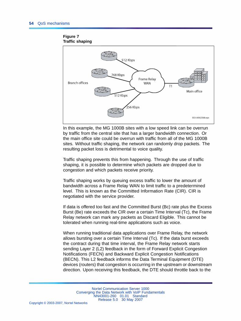
54 QoS mechanisms
Figure 7Traffic shaping
In this example, the MG 1000B sites with a low speed link can be overrunby traffic from the central site that has a larger bandwidth connection. Orthe main office site could be overrun with traffic from all of the MG 1000Bsites. Without traffic shaping, the network can randomly drop packets. Theresulting packet loss is detrimental to voice quality.
Traffic shaping prevents this from happening. Through the use of trafficshaping, it is possible to determine which packets are dropped due tocongestion and which packets receive priority.
Traffic shaping works by queuing excess traffic to lower the amount ofbandwidth across a Frame Relay WAN to limit traffic to a predeterminedlevel. This is known as the Committed Information Rate (CIR). CIR isnegotiated with the service provider.
If data is offered too fast and the Committed Burst (Bc) rate plus the ExcessBurst (Be) rate exceeds the CIR over a certain Time Interval (Tc), the FrameRelay network can mark any packets as Discard Eligible. This cannot betolerated when running real-time applications such as voice.
When running traditional data applications over Frame Relay, the networkallows bursting over a certain Time Interval (Tc). If the data burst exceedsthe contract during that time interval, the Frame Relay network startssending Layer 2 (L2) feedback in the form of Forward Explicit CongestionNotifications (FECN) and Backward Explicit Congestion Notifications(BECN). This L2 feedback informs the Data Terminal Equipment (DTE)devices (routers) that congestion is occurring in the upstream or downstreamdirection. Upon receiving this feedback, the DTE should throttle back to the
Nortel Communication Server 1000Converging the Data Network with VoIP Fundamentals
NN43001-260 01.01 StandardRelease 5.0 30 May 2007
Copyright © 2003-2007, Nortel Networks
.
WAN QoS mechanisms 55
Committed Burst (Bc) or a fraction of the Bc. It is also possible for the DTEto completely shutdown until the feedback indication abates for a periodof time.
While this is considered a benefit for data applications, the resulting packetloss is detrimental to quality.
RTP header compressionIP Real-time Transport Protocol (RTP) header compression can be usedto compress 40-byte (IP, UDP, RTP) VoIP packet headers down to a sizeof 2 to 4 bytes.
This results in significant bandwidth savings across low-bandwidth WANlinks. It is important to note current WAN platform CPU levels beforeimplementing RTP header compression, because it is CPU intensive.
PPP QoSIt is important that QoS mechanisms are used over low-bandwidth linksthat carry both voice and data traffic.
Implementing QoS mechanisms over a PPP WAN link may involve the useof the following:
• priority queuing (possibly mapped from the Diffserv CodePoint (DSCP))
• RTP header compression
• fragmentation and interleaving
Frame Relay QoSNortel recommends separate Permanent Virtual Circuits (PVCs) for voiceand data whenever possible. Ensure voice PVCs strictly conform to theCIR. Do not allow bursting or shaping. It can be beneficial to use partiallymeshed PVCs, depending on traffic patterns.
If voice and data traffic share the same PVC, it can be necessary to usepriority queuing along with traffic shaping to ensure that voice packets arenot discarded or queued for a long period time. On low bandwidth links (<1Mbps), fragmentation and interleaving (FRF.12) may have to be used.
ATM QoSTwo methods of ensuring VoIP QoS on ATM links are available:
• separate voice and data PVCs
• priority queuing on a shared voice and data PVC
Nortel Communication Server 1000Converging the Data Network with VoIP Fundamentals
NN43001-260 01.01 StandardRelease 5.0 30 May 2007
Copyright © 2003-2007, Nortel Networks
.
56 QoS mechanisms
Nortel recommends separate voice and data PVCs. The availablebandwidth for a particular ATM PVC is usually guaranteed by a serviceprovider. If traffic through the PVC is restricted to VoIP traffic only, then noother QoS mechanisms in the ATM network must be used. Voice trafficcan be mapped into the voice-only PVC according to source IP address orDiffserv CodePoint. VoIP bandwidth management on the Call Server canthen be used to ensure that the VoIP traffic volume does not exceed theamount of bandwidth available in the voice-only PVC.
If a shared voice and data PVC is used, then priority queuing must beconfigured across the ATM network to guarantee that voice traffic haspriority over data traffic.
Layer 2 (Ethernet) QoSAt Layer 2, VoIP packets can be classified by the following fields in theEthernet header:
• source/destination MAC address
• 802.1Q
— VLAN ID
— 802.1p user priority bits
MAC addressAll MAC addresses are unique and should not be changed.
Packets can be classified by the MAC address. Packets from a Nortel IPPhone can be recognized because each Nortel IP Phone has a uniqueset of MAC addresses. When the Layer 2 switch recognizes the IP Phonepacket’s MAC address, it marks the packets with the appropriate 802.1pvalue. Then the Layer 2 switch places the packets in the correct switchqueue. The correct queue is determined by the QoS policy implemented bythe network administrator.
IEEE 802.1QThe IEEE 802.1Q standard extends the Ethernet frame format by addingfour bytes to the Ethernet packet header. See Figure 8 "Ethernet 802.1Qextensions" (page 57).
The 802.1Q extensions contain two important fields – the 802.1p field andthe VLAN ID field. Table 4 "IEEE 802.1Q field definitions" (page 57) lists the802.1Q field names and their definitions.
Nortel Communication Server 1000Converging the Data Network with VoIP Fundamentals
NN43001-260 01.01 StandardRelease 5.0 30 May 2007
Copyright © 2003-2007, Nortel Networks
.
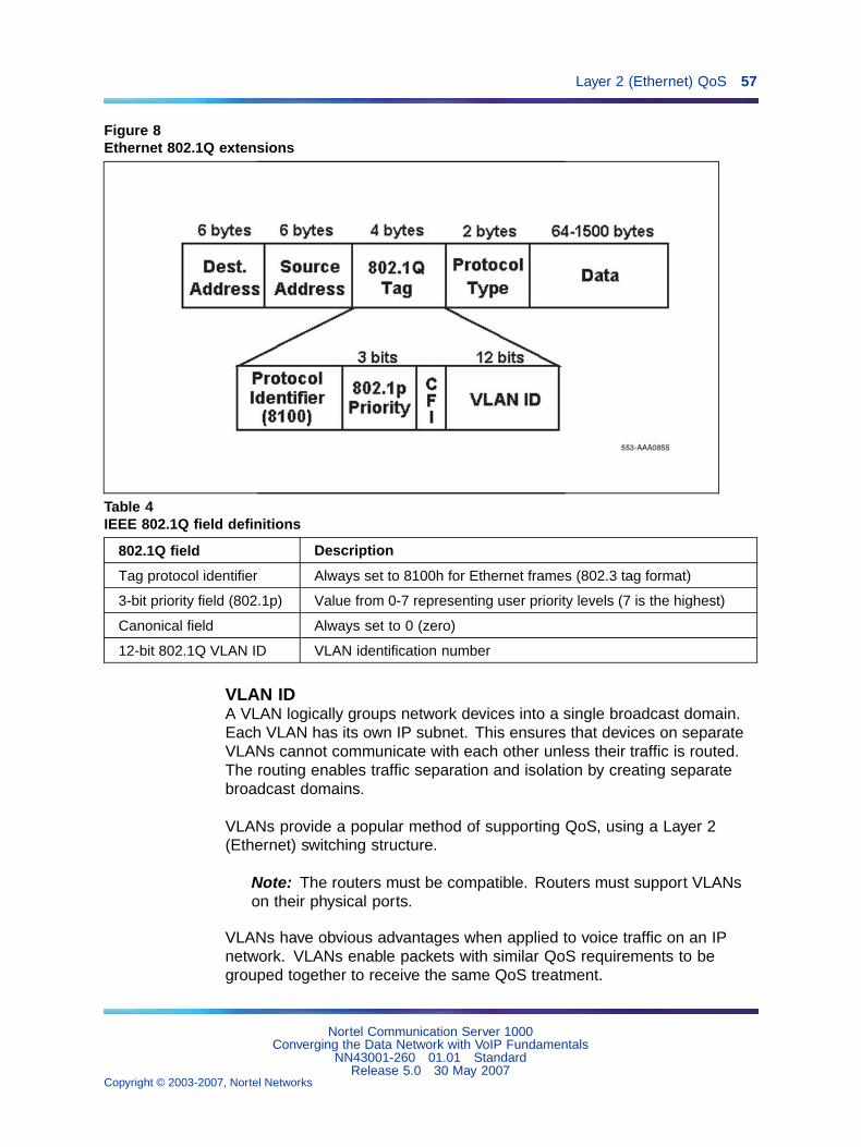
Layer 2 (Ethernet) QoS 57
Figure 8Ethernet 802.1Q extensions
Table 4IEEE 802.1Q field definitions
802.1Q field Description
Tag protocol identifier Always set to 8100h for Ethernet frames (802.3 tag format)
3-bit priority field (802.1p) Value from 0-7 representing user priority levels (7 is the highest)
Canonical field Always set to 0 (zero)
12-bit 802.1Q VLAN ID VLAN identification number
VLAN IDA VLAN logically groups network devices into a single broadcast domain.Each VLAN has its own IP subnet. This ensures that devices on separateVLANs cannot communicate with each other unless their traffic is routed.The routing enables traffic separation and isolation by creating separatebroadcast domains.
VLANs provide a popular method of supporting QoS, using a Layer 2(Ethernet) switching structure.
Note: The routers must be compatible. Routers must support VLANson their physical ports.
VLANs have obvious advantages when applied to voice traffic on an IPnetwork. VLANs enable packets with similar QoS requirements to begrouped together to receive the same QoS treatment.
Nortel Communication Server 1000Converging the Data Network with VoIP Fundamentals
NN43001-260 01.01 StandardRelease 5.0 30 May 2007
Copyright © 2003-2007, Nortel Networks
.
58 QoS mechanisms
Note: When routing into a specific VLAN, configure the router interfaceto tag the incoming Layer 2 Ethernet frames with the correct VLAN IDand priority.
VLANs provide a useful way to separate and prioritize the IP telephonypackets for Layer 2 switches. A telephony VLAN can be created so that allIP telephony devices are members. This enables the Layer 2 switch toprioritize all telephony traffic so that it all receives consistent QoS treatment.
Note: A VLAN can only provide QoS on Layer 2 switches that supportthe 802.1Q (VLAN) standard. Once the packets leave the Layer 2switch, and encounter routers or WAN switches, DiffServ should beused to provide end-to-end QoS. Nortel IP Phones also mark the DSCP,so when voice packets encounter routers, the routers can be configuredto prioritize the packets based on their DSCP value.
IP Phones 200x support IEEE 802.1Q using firmware version 1.39 or later.The default Ethernet Class of Service (CoS) is 0; this is the same as the802.1Q priority bits.
The IP Phones 200x firmware tags the ethernet frames with both thetelephone’s VLAN ID and the 802.1p priority specified in Element Manager.The recommended 802.1p priority is 6.
The Nortel IP Softphone 2050 client support of IEEE 802.1Q prioritydepends on the underlying operating system and hardware.
802.1p user priority bitsThe 802.1p field has three bits to provide eight Classes of Service (CoS).802.1p-capable L2/L3 switches use these Classes of Service to prioritizepackets, and then place them in different queues. This provides servicedifferentiation.
802.1p configurationUse Procedure 2 "Configuring 802.1p priority bits in Element Manager"(page 58) to configure the 802.1p priority bits in Element Manager.
See Element Manager System Reference - Administration (NN43001-632)for more information on Element Manager.
Procedure 2Configuring 802.1p priority bits inElement Manager
Step Action
1 Select IP Telephony > Nodes: Servers, Media Cards >Configuration from the Element Manager navigator.
Nortel Communication Server 1000Converging the Data Network with VoIP Fundamentals
NN43001-260 01.01 StandardRelease 5.0 30 May 2007
Copyright © 2003-2007, Nortel Networks
.
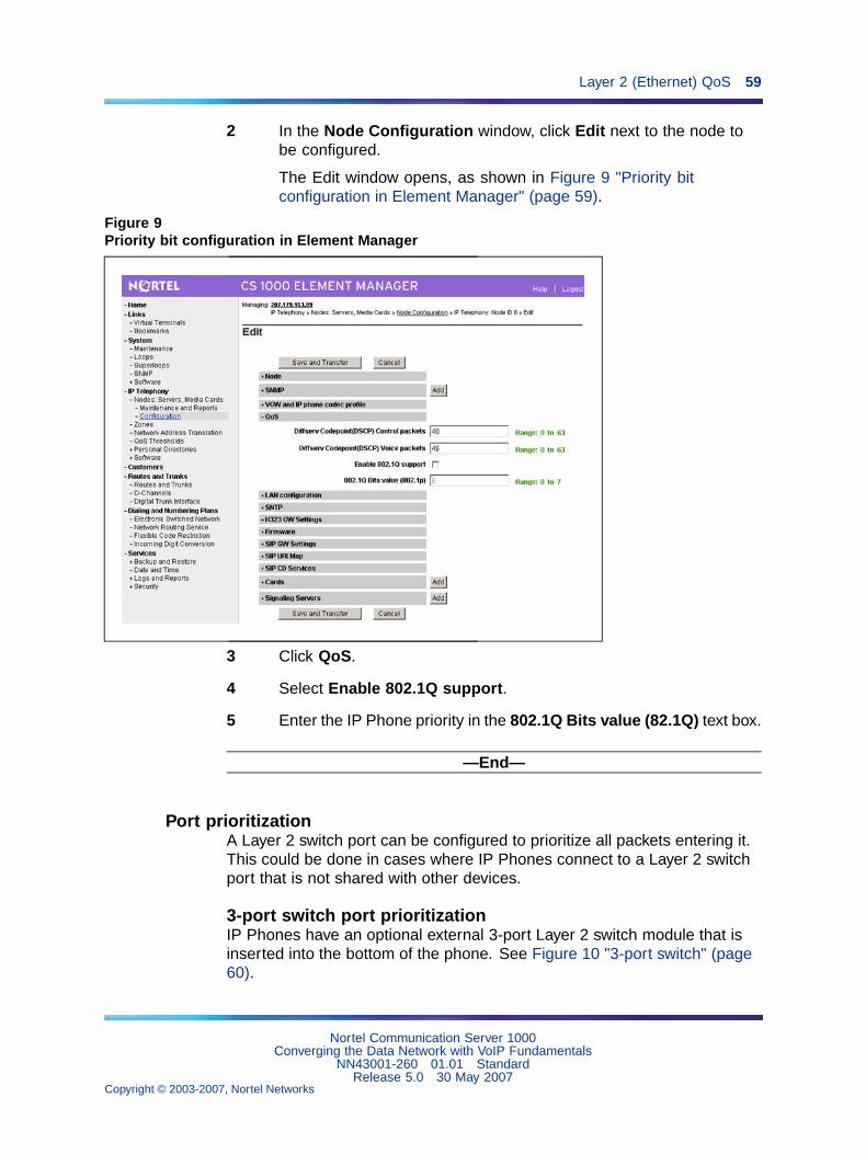
Layer 2 (Ethernet) QoS 59
2 In the Node Configuration window, click Edit next to the node tobe configured.
The Edit window opens, as shown in Figure 9 "Priority bitconfiguration in Element Manager" (page 59).
Figure 9Priority bit configuration in Element Manager
3 Click QoS.
4 Select Enable 802.1Q support.
5 Enter the IP Phone priority in the 802.1Q Bits value (82.1Q) text box.
—End—
Port prioritizationA Layer 2 switch port can be configured to prioritize all packets entering it.This could be done in cases where IP Phones connect to a Layer 2 switchport that is not shared with other devices.
3-port switch port prioritizationIP Phones have an optional external 3-port Layer 2 switch module that isinserted into the bottom of the phone. See Figure 10 "3-port switch" (page60).
Nortel Communication Server 1000Converging the Data Network with VoIP Fundamentals
NN43001-260 01.01 StandardRelease 5.0 30 May 2007
Copyright © 2003-2007, Nortel Networks
.
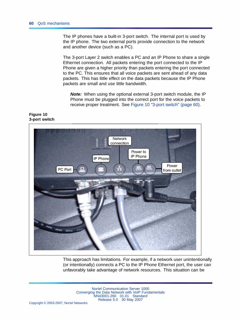
60 QoS mechanisms
The IP phones have a built-in 3-port switch. The internal port is used bythe IP phone. The two external ports provide connection to the networkand another device (such as a PC).
The 3-port Layer 2 switch enables a PC and an IP Phone to share a singleEthernet connection. All packets entering the port connected to the IPPhone are given a higher priority than packets entering the port connectedto the PC. This ensures that all voice packets are sent ahead of any datapackets. This has little effect on the data packets because the IP Phonepackets are small and use little bandwidth.
Note: When using the optional external 3-port switch module, the IPPhone must be plugged into the correct port for the voice packets toreceive proper treatment. See Figure 10 "3-port switch" (page 60).
Figure 103-port switch
This approach has limitations. For example, if a network user unintentionally(or intentionally) connects a PC to the IP Phone Ethernet port, the user canunfavorably take advantage of network resources. This situation can be
Nortel Communication Server 1000Converging the Data Network with VoIP Fundamentals
NN43001-260 01.01 StandardRelease 5.0 30 May 2007
Copyright © 2003-2007, Nortel Networks
.
Layer 3 QoS 61
prevented by ensuring that all packets entering the port are also prioritizedthrough MAC or VLAN ID classification to determine that they are froman IP Phone.
Recommendation
Nortel strongly recommends that, for stationary IP telephony devices such asVoIP gateways, use port prioritization on the Ethernet switch port that connectsto the device.
Layer 3 QoSDiffServ is the recommended Layer 3 QoS mechanism. Newer Layer 3 IPdevices (routers and Layer 3 switches) can classify IP Phone packets byusing the following fields in the IP packet header:
• source/destination IP address
• DiffServ CodePoint (DSCP)(the 6 Most Significant Bits (MSB) in the 8-bit DiffServ field)
ATTENTIONIMPORTANT!The values entered in these two fields must be coordinated across the entire IPdata network. Do not change them arbitrarily.
IP address classificationA Nortel IP Phone obtains its IP address in one of two ways:
• DHCP is used to automatically obtain the IP address.
• the IP address is permanently assigned through the keypad.
To make it easier to prioritize packets by IP addresses, a pool of IPaddresses can be set aside exclusively for IP Phones. The Layer 3switch/router can then prioritize the packets based on this range of IPaddresses. It marks the voice packets from those designated IP addresseswith the recommended DSCP.
This method does not differentiate between voice media and signalingpackets. Only a single DSCP is used for both. However, if additional filtersare applied to sort the different packet types, the voice media and signalingpackets can be marked with different DSCPs.
DiffServ for VoIPDiffServ-based QoS at Layer 3 provides end-to-end QoS. By using DSCP,DiffServ enables service assignment to network traffic on a per-hop basis.
Figure 11 "DiffServ-based QoS architecture" (page 62) shows thearchitecture of DiffServ-based QoS.
Nortel Communication Server 1000Converging the Data Network with VoIP Fundamentals
NN43001-260 01.01 StandardRelease 5.0 30 May 2007
Copyright © 2003-2007, Nortel Networks
.
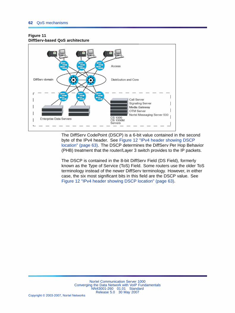
62 QoS mechanisms
Figure 11DiffServ-based QoS architecture
The DiffServ CodePoint (DSCP) is a 6-bit value contained in the secondbyte of the IPv4 header. See Figure 12 "IPv4 header showing DSCPlocation" (page 63). The DSCP determines the DiffServ Per Hop Behavior(PHB) treatment that the router/Layer 3 switch provides to the IP packets.
The DSCP is contained in the 8-bit DiffServ Field (DS Field), formerlyknown as the Type of Service (ToS) Field. Some routers use the older ToSterminology instead of the newer DiffServ terminology. However, in eithercase, the six most significant bits in this field are the DSCP value. SeeFigure 12 "IPv4 header showing DSCP location" (page 63).
Nortel Communication Server 1000Converging the Data Network with VoIP Fundamentals
NN43001-260 01.01 StandardRelease 5.0 30 May 2007
Copyright © 2003-2007, Nortel Networks
.
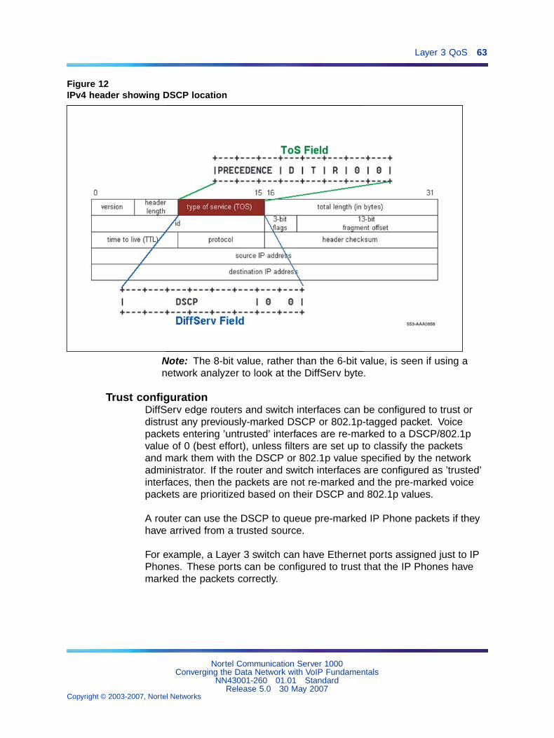
Layer 3 QoS 63
Figure 12IPv4 header showing DSCP location
Note: The 8-bit value, rather than the 6-bit value, is seen if using anetwork analyzer to look at the DiffServ byte.
Trust configurationDiffServ edge routers and switch interfaces can be configured to trust ordistrust any previously-marked DSCP or 802.1p-tagged packet. Voicepackets entering ’untrusted’ interfaces are re-marked to a DSCP/802.1pvalue of 0 (best effort), unless filters are set up to classify the packetsand mark them with the DSCP or 802.1p value specified by the networkadministrator. If the router and switch interfaces are configured as ’trusted’interfaces, then the packets are not re-marked and the pre-marked voicepackets are prioritized based on their DSCP and 802.1p values.
A router can use the DSCP to queue pre-marked IP Phone packets if theyhave arrived from a trusted source.
For example, a Layer 3 switch can have Ethernet ports assigned just to IPPhones. These ports can be configured to trust that the IP Phones havemarked the packets correctly.
Nortel Communication Server 1000Converging the Data Network with VoIP Fundamentals
NN43001-260 01.01 StandardRelease 5.0 30 May 2007
Copyright © 2003-2007, Nortel Networks
.
64 QoS mechanisms
Voice signaling and media DSCPsOver a high bandwidth, low latency Ethernet LAN connection, voice mediapackets and signaling packets can be placed in the same queue in the Layer2 or Layer 3 switch. In this case, it is not necessary to differentiate betweenvoice media packets and voice signaling packets.
However, when the voice packets use a low-bandwidth (less than 1 Mbps)connection, considerable queuing delay can occur. This queuing delay,when coupled with the arrival of different-sized voice packets (signalingand media), creates an unacceptable amount of voice jitter, which in turnresults in poor voice quality.
To minimize voice jitter over low bandwidth connections, the voice mediapackets and voice signaling packets must be separated into differentqueues. By marking the voice media packets and voice signaling packetswith a different DSCP, the packets can be classified and separated intodifferent queues by the router connected to the low-bandwidth connection.
Note: It is important to categorize signaling packets so they are notdiscarded by the network. The IP Phone contains a watchdog timer thatresets the IP Phone if signaling packets are not seen within a certainamount of time. Lost signaling packets can also cause the IP Phonesto reset.
Setting DSCP valuesIf a best-effort network is currently in place, and VoIP is being added, thesimplest approach is to create the network QoS with only three prioritylevels:
1. VoIP voice media traffic
2. VoIP signaling traffic
3. best-effort IP data traffic
Routers connected to low-bandwidth interfaces must separate voice mediapackets and voice signaling packets. This is necessary to minimize jitterthat was introduced by the signaling packets to the voice media packets.This jitter occurs if the packets are placed in the same queue instead ofseparate queues.
IP packets are prioritized based on the DSCP in the distribution layer, corelayer and WAN.
DiffServ is supported on the Signaling Server, Voice Gateway Media Cards,and the IP Phones.
Nortel Communication Server 1000Converging the Data Network with VoIP Fundamentals
NN43001-260 01.01 StandardRelease 5.0 30 May 2007
Copyright © 2003-2007, Nortel Networks
.
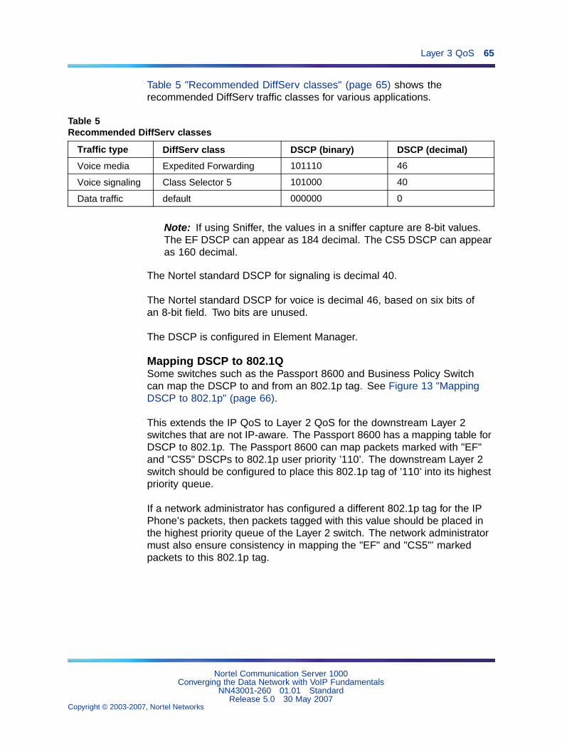
Layer 3 QoS 65
Table 5 "Recommended DiffServ classes" (page 65) shows therecommended DiffServ traffic classes for various applications.
Table 5Recommended DiffServ classes
Traffic type DiffServ class DSCP (binary) DSCP (decimal)
Voice media Expedited Forwarding 101110 46
Voice signaling Class Selector 5 101000 40
Data traffic default 000000 0
Note: If using Sniffer, the values in a sniffer capture are 8-bit values.The EF DSCP can appear as 184 decimal. The CS5 DSCP can appearas 160 decimal.
The Nortel standard DSCP for signaling is decimal 40.
The Nortel standard DSCP for voice is decimal 46, based on six bits ofan 8-bit field. Two bits are unused.
The DSCP is configured in Element Manager.
Mapping DSCP to 802.1QSome switches such as the Passport 8600 and Business Policy Switchcan map the DSCP to and from an 802.1p tag. See Figure 13 "MappingDSCP to 802.1p" (page 66).
This extends the IP QoS to Layer 2 QoS for the downstream Layer 2switches that are not IP-aware. The Passport 8600 has a mapping table forDSCP to 802.1p. The Passport 8600 can map packets marked with "EF"and "CS5" DSCPs to 802.1p user priority ’110’. The downstream Layer 2switch should be configured to place this 802.1p tag of ’110’ into its highestpriority queue.
If a network administrator has configured a different 802.1p tag for the IPPhone’s packets, then packets tagged with this value should be placed inthe highest priority queue of the Layer 2 switch. The network administratormust also ensure consistency in mapping the "EF" and "CS5"’ markedpackets to this 802.1p tag.
Nortel Communication Server 1000Converging the Data Network with VoIP Fundamentals
NN43001-260 01.01 StandardRelease 5.0 30 May 2007
Copyright © 2003-2007, Nortel Networks
.
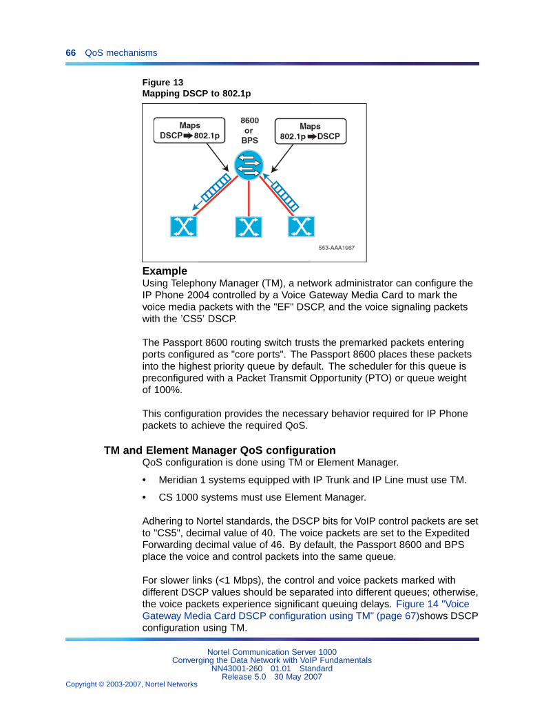
66 QoS mechanisms
Figure 13Mapping DSCP to 802.1p
ExampleUsing Telephony Manager (TM), a network administrator can configure theIP Phone 2004 controlled by a Voice Gateway Media Card to mark thevoice media packets with the "EF" DSCP, and the voice signaling packetswith the ’CS5’ DSCP.
The Passport 8600 routing switch trusts the premarked packets enteringports configured as "core ports". The Passport 8600 places these packetsinto the highest priority queue by default. The scheduler for this queue ispreconfigured with a Packet Transmit Opportunity (PTO) or queue weightof 100%.
This configuration provides the necessary behavior required for IP Phonepackets to achieve the required QoS.
TM and Element Manager QoS configurationQoS configuration is done using TM or Element Manager.
• Meridian 1 systems equipped with IP Trunk and IP Line must use TM.
• CS 1000 systems must use Element Manager.
Adhering to Nortel standards, the DSCP bits for VoIP control packets are setto "CS5", decimal value of 40. The voice packets are set to the ExpeditedForwarding decimal value of 46. By default, the Passport 8600 and BPSplace the voice and control packets into the same queue.
For slower links (<1 Mbps), the control and voice packets marked withdifferent DSCP values should be separated into different queues; otherwise,the voice packets experience significant queuing delays. Figure 14 "VoiceGateway Media Card DSCP configuration using TM" (page 67)shows DSCPconfiguration using TM.
Nortel Communication Server 1000Converging the Data Network with VoIP Fundamentals
NN43001-260 01.01 StandardRelease 5.0 30 May 2007
Copyright © 2003-2007, Nortel Networks
.
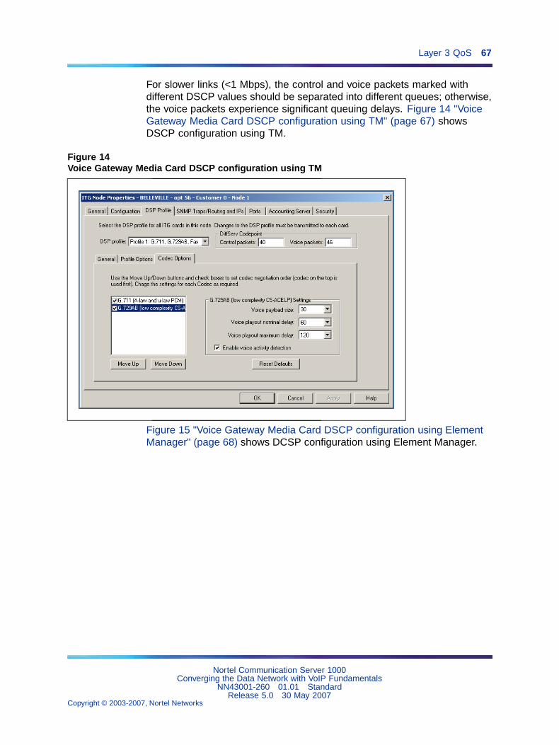
Layer 3 QoS 67
For slower links (<1 Mbps), the control and voice packets marked withdifferent DSCP values should be separated into different queues; otherwise,the voice packets experience significant queuing delays. Figure 14 "VoiceGateway Media Card DSCP configuration using TM" (page 67) showsDSCP configuration using TM.
Figure 14Voice Gateway Media Card DSCP configuration using TM
Figure 15 "Voice Gateway Media Card DSCP configuration using ElementManager" (page 68) shows DCSP configuration using Element Manager.
Nortel Communication Server 1000Converging the Data Network with VoIP Fundamentals
NN43001-260 01.01 StandardRelease 5.0 30 May 2007
Copyright © 2003-2007, Nortel Networks
.
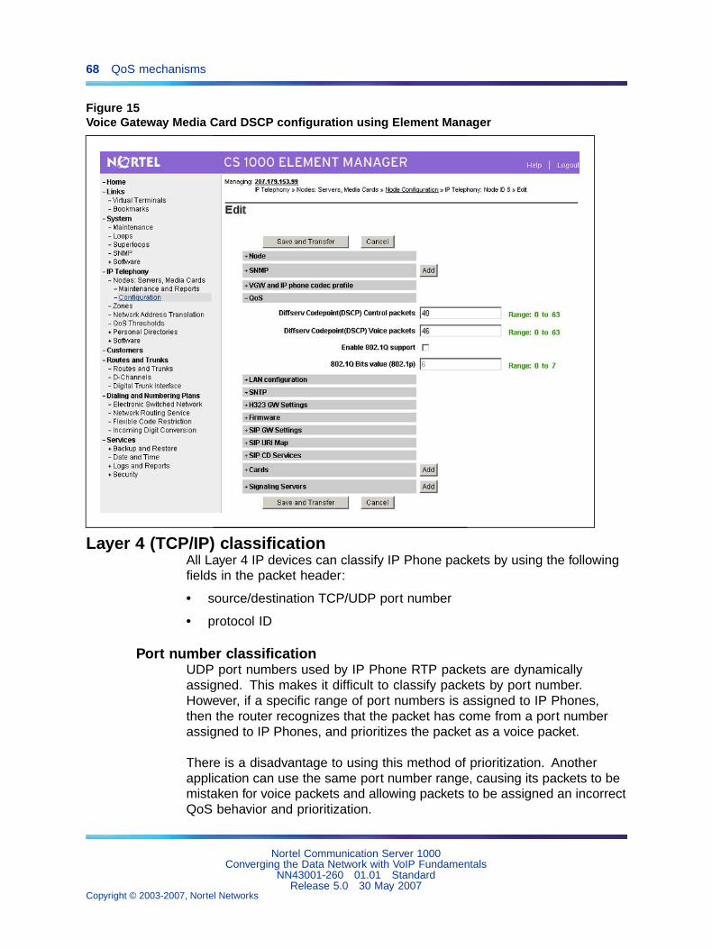
68 QoS mechanisms
Figure 15Voice Gateway Media Card DSCP configuration using Element Manager
Layer 4 (TCP/IP) classificationAll Layer 4 IP devices can classify IP Phone packets by using the followingfields in the packet header:
• source/destination TCP/UDP port number
• protocol ID
Port number classificationUDP port numbers used by IP Phone RTP packets are dynamicallyassigned. This makes it difficult to classify packets by port number.However, if a specific range of port numbers is assigned to IP Phones,then the router recognizes that the packet has come from a port numberassigned to IP Phones, and prioritizes the packet as a voice packet.
There is a disadvantage to using this method of prioritization. Anotherapplication can use the same port number range, causing its packets to bemistaken for voice packets and allowing packets to be assigned an incorrectQoS behavior and prioritization.
Nortel Communication Server 1000Converging the Data Network with VoIP Fundamentals
NN43001-260 01.01 StandardRelease 5.0 30 May 2007
Copyright © 2003-2007, Nortel Networks
.
Bandwidth Management 69
Protocol ID classificationThe Real-time Transport Protocol (RTP) is used by many multimediaapplications such as real-time fax and video, as well as voice. Prioritizingpackets according to the protocol used, therefore, cannot be used toaccurately prioritize the voice packets.
CS 1000 and Meridian 1 portsSee Appendix "Port number tables" (page 213) for more information.
Policy managementPrioritization of traffic can also be implemented through policy management.Nortel supports this option through Optivity Policy Services software.
Optivity Policy ServicesOptivity Policy Services (OPS) is network-management software thatenables the network administrator to prioritize and manage different typesof network traffic. OPS 2.0 is designed to manage policies on the BPS andBusiness Communication Server (BCM). To manage BayRS, Accelar, andPassport devices, OPS 1.1.1 must be installed.
See Appendix "DHCP supplemental information" (page 231) forconfiguration examples.
Bandwidth ManagementThis section provides an overview of how the Bandwidth Managementfeature works, and is useful when considering how to engineer a networkof Call Servers. For additional information on the detailed configuration ofBandwidth Management, refer to the following:
• IP Peer Networking Installation and Commissioning (NN43001-313)
• Branch Office Installation and Commissioning (NN43001-314)
• Main Office Configuration for Survivable Remote Gateway 50 MainOffice Configuration for SRG200/400 Release 1.5 (NN43001-307)
Bandwidth management provides a means of controlling the amount ofVoice over IP (VoIP) traffic in an IP network. Call Servers in the networkkeep track of the various amounts of VoIP traffic and provide treatment toVoIP calls. Treatment may consist of blocking new calls (Call AdmissionControl) or rerouting them if there is not the required bandwidth available.For example, when a caller attempts to make a VoIP call and the bandwidthlimit has been reached, the call is blocked or rerouted.
Bandwidth Management also allows for a particular CODEC to be selecteddepending on the type of call — whether it is a local call within the LAN or aremote call across a WAN.
Nortel Communication Server 1000Converging the Data Network with VoIP Fundamentals
NN43001-260 01.01 StandardRelease 5.0 30 May 2007
Copyright © 2003-2007, Nortel Networks
.
70 QoS mechanisms
Bandwidth Management is considered a QoS mechanism because itprovides a means of guaranteeing that VoIP traffic does not use morenetwork bandwidth than is available.
Bandwidth Management Zones simplify VoIP network voice engineering.Bandwidth Management Zones allow an administrator to simply enter theamount of bandwidth available for voice on the IP network, instead ofdetailed voice CCS calculations across a particular link.
For example, if a CCS-type approach to VoIP network voice engineering isused, an administrator must calculate the maximum CCS expected betweensites A to B, A to C, and B to C, and subsequently engineer the networkto support the required call volume.
Alternatively, through the use of Bandwidth Management Zones, anadministrator may enter the amount of bandwidth available for voice onthe IP network into the Call Server. The amount of bandwidth is ensuredusing other QoS mechanisms, such as priority, as well as the type ofvoice CODEC that is used. The Call Server then ensures that the VoIPcall volume entering or leaving a zone does not exceed the IP networkbandwidth available. This enables users to avoid quality degradationbecause of insufficient bandwidth for active connections.
Call admission control applies equally well to a single distributed systemwith centralized call control, or multiple systems, as in the case of a mainsite with numerous branch offices connected with VoIP.
Figure 16 "Bandwidth management example" (page 71) shows an exampleof Bandwidth Management.
Nortel Communication Server 1000Converging the Data Network with VoIP Fundamentals
NN43001-260 01.01 StandardRelease 5.0 30 May 2007
Copyright © 2003-2007, Nortel Networks
.
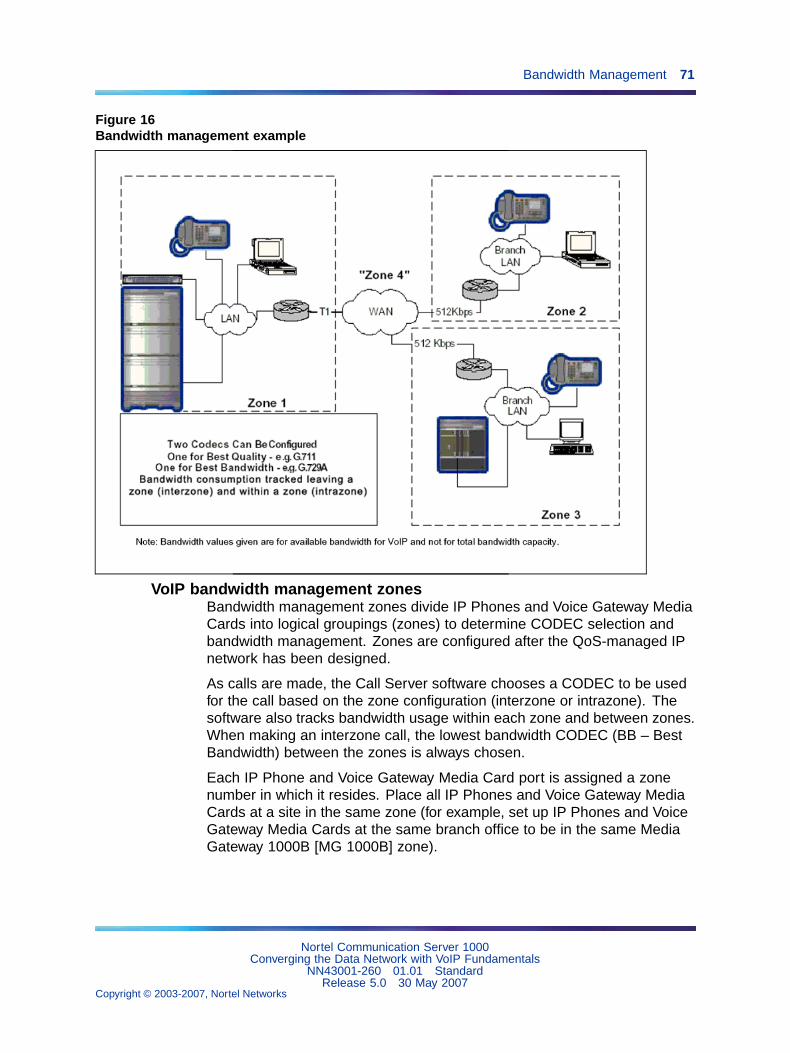
Bandwidth Management 71
Figure 16Bandwidth management example
VoIP bandwidth management zonesBandwidth management zones divide IP Phones and Voice Gateway MediaCards into logical groupings (zones) to determine CODEC selection andbandwidth management. Zones are configured after the QoS-managed IPnetwork has been designed.
As calls are made, the Call Server software chooses a CODEC to be usedfor the call based on the zone configuration (interzone or intrazone). Thesoftware also tracks bandwidth usage within each zone and between zones.When making an interzone call, the lowest bandwidth CODEC (BB – BestBandwidth) between the zones is always chosen.
Each IP Phone and Voice Gateway Media Card port is assigned a zonenumber in which it resides. Place all IP Phones and Voice Gateway MediaCards at a site in the same zone (for example, set up IP Phones and VoiceGateway Media Cards at the same branch office to be in the same MediaGateway 1000B [MG 1000B] zone).
Nortel Communication Server 1000Converging the Data Network with VoIP Fundamentals
NN43001-260 01.01 StandardRelease 5.0 30 May 2007
Copyright © 2003-2007, Nortel Networks
.
72 QoS mechanisms
Virtual Trunk routes also allow configuration of a zone. A single Call Serverconsiders calls out from a Virtual Trunk to be terminated on that VirtualTrunk. Therefore, Virtual Trunks should not be in the same zones as any IPPhones or Voice Gateway Media Cards.
Place all virtual trunk routes in the same zone for all main office and MG1000B systems. Virtual trunk zones are not for bandwidth managementexcept when connecting to a third-party gateway. Set virtual trunk intrazoneCODECs to Best Quality (BQ), and set virtual trunk interzone CODECs toBest Bandwidth (BB). Set virtual trunk intrazone and interzone bandwidthto the maximum value of 1 Gbps (1 000 000 Kbps). Bandwidth is alreadymanaged within the IP Phone zone.
Zones are network-wide, therefore zone numbers must not be duplicated.If zone numbers are duplicated on different systems, a call may appear tobe an intrazone call. The network-wide zone number is the "vpni" plus thebandwidth zone number. Ensure "vpni" in the customer data block is set tothe same value on all systems within the same network (for example, mainoffice or MG 1000B groupings). Calls between two systems with differentvpni’s are treated as interzone calls.
MG 1000B zones should be configured on the MG 1000B and main officesystems. The MG 1000B zones only contain equipment located at thatbranch office. The information configured for the zone should be identical inboth the main and MG 1000B configuration. Main office zone informationdoes not have to be entered into all MG 1000Bs.
Zone properties are defined in LD 117. A maximum of 256 zones can beconfigured. The systems use the zones for bandwidth management. Newcalls are blocked when the bandwidth limit is reached.
Each zone has six parameters. The prompt lists the parameters as:
• p1 — The total bandwidth available for intrazone calls
• p2 — The preferred strategy for the choice of CODEC for intrazone calls(that is, preserve best quality or best bandwidth)
• p3 — The total bandwidth available for interzone calls
• p4 — The preferred strategy for the choice of the CODEC for interzonecalls
• p5 — The zone intent, whether the zone will be part of the main office, abranch office (Media Gateway 1000B [MG 1000B]), or a Virtual Trunk.
• p6 — The zone resource type, either shared or private. Resources inprivate zones are accessible to users in the same zone. This allowsresources, such as DSPs, to be reserved for users in the private zone.
Nortel Communication Server 1000Converging the Data Network with VoIP Fundamentals
NN43001-260 01.01 StandardRelease 5.0 30 May 2007
Copyright © 2003-2007, Nortel Networks
.
Bandwidth Management 73
The intrazone and interzone bandwidth is entered in Kbps (for example, 2.7Mbps equals 2700 Kbps). Each bandwidth zone must have the intrazoneand interzone bandwidth values entered.
If no IP voice zones are configured, zone 0 operates as a default zone. Ifno IP voice zones are configured in LD 117, zone 0 can be configured forITG Physical TNs (IPTN) in LD 14, and for virtual line in LD 11 as a defaultzone. However, if any additional zones are required, zone 0 must be firstconfigured in LD 117 if it is referenced by any IP Phone or IPTN. If zone 0 isnot configured first, then all calls in zone 0 are labeled as soon as anotherzone is configured in LD 117.
CAUTIONWhen moving an IP Phone, the system administrator should checkand change, if necessary, the zone assignment of the telephone inLD 11. See Software Input Output: Administration (NN43001-611).
CAUTIONZone 0 must be configured in LD 117 before other zones areconfigured or all calls associated with zone 0 are blocked.
Configuring endpoints in bandwidth zone 0 is not a supported configuration.Configure zone 0, but do not use it. Ensure that no endpoints (for example,IP Phones, VGWs, or vtrks) are in zone 0.
Interzone vs. IntrazoneFor Bandwidth Management, a network of Call Servers is divided intozones, typically one zone for each Call Server. Calls between zones areknown as interzone calls. Calls within a zone are intrazone calls. Typically,intrazone calls travel over LANs on which bandwidth is widely available.Conversely, interzone calls travel over WANs on which bandwidth can belimited and expensive. Differentiating intrazone and interzone VoIP callsallows for increased control over the VoIP traffic.
The following call scenarios describe how each call type works.
Intrazone callAn intrazone call works as follows:
• An intrazone call is made between two endpoints on the same CallServer.
Nortel Communication Server 1000Converging the Data Network with VoIP Fundamentals
NN43001-260 01.01 StandardRelease 5.0 30 May 2007
Copyright © 2003-2007, Nortel Networks
.
74 QoS mechanisms
• The intrazone treatment is consulted to determine whether it is BestBandwidth or Best Quality.
• Based on the intrazone treatment, the correct codec is selected.
• The intrazone bandwidth table is also consulted to determine if there isenough intrazone bandwidth to support the call. If there is not enoughbandwidth, the call is blocked.
Interzone callAn interzone call works as follows:
• An intrazone call is made between an endpoint in one zone to anotherendpoint in a different zone. The zone of the endpoints are comparedto the Virtual Trunk zone. Since the two zones are different, the callis an interzone call.
• The interzone treatment is consulted to determine whether it is BestBandwidth or Best Quality.
• Based on the interzone treatment, the correct codec list is selected forthe call setup. See "CODEC selection" (page 76) for more informationon codec selection.
• The interzone bandwidth table and the virtual trunk bandwidth limit arealso consulted to determine if there is enough intrazone bandwidth tosupport the call. If there is not enough bandwidth, the call is blocked,or alternate treatment is provided.
Bandwidth Management is nodalBandwidth Management is controlled independently on each Call Server inthe network. This means that each Call Server acts independently of otherCall Servers in the network when calculating bandwidth used, and whenblocking or re-routing calls. This is called "nodal" Bandwidth Management— each node, or Call Server, independently controls the BandwidthManagement. Therefore, the parameters used in configuring BandwidthManagement must be configured on each Call Server.
The exception to this rule is at the branch office. The BandwidthManagement at the branch office is controlled by the associated main office.For the main office to keep track of the bandwidth going to and from thebranch office, calls must be tandemed through the main office Call Server.This means that the signaling for the call goes through the main office butthe media path is not direct between endpoints.
VPNI and Zone numbersBandwidth ZoneIn order for bandwidth management to work correctly in a CS1000 network,each Call Server must be configured with a unique Network BandwidthZone. There are 256 (0-255) Zone numbers available to choose from in a
Nortel Communication Server 1000Converging the Data Network with VoIP Fundamentals
NN43001-260 01.01 StandardRelease 5.0 30 May 2007
Copyright © 2003-2007, Nortel Networks
.
Bandwidth Management 75
CS1000 Call Server. To allow the network to expand beyond the 256 zones,the Virtual Private Network Identifier (VPNI) is combined with the Zonenumber to form a unique Network Bandwidth Zone. The CS1000 systemallows for up to 16283 VPNIs which results in a total of 4,152,165 uniqueNetwork Bandwidth Zones. A Call Server typically has one VPNI and oneZone number for IP Phones and IP gateways. For example, Call Server A isprovisioned with VPNI 53 and zone 21.
VPNI and Zone numbering rulesBandwidth Zones are network-wide therefore Bandwidth Zone numbersmust not be duplicated at different Call Servers. If these numbers areduplicated on different systems, a call can appear to be an intrazone call. Toensure uniqueness and correct functionality, every main office Call Server inthe network must have a unique VPNI.
Branch office Call Servers associated with a main office must have thesame VPNI number as the main office. This allows for the correct operationof the Network Bandwidth Management feature.
For a branch office associated with a main office, the branch office Zonenumber must be different than the main office Zone number. For example,the following is an acceptable configuration: MO VPNI=22, MO Zone=33,BO VPNI=22, BO Zone=34. The branch office zone number is provisionedat both the branch office and the main office. These are configured in LD117 on the main office and MG1000B.
The provisioned Zone number is also used for other features in the CS 1000network. See Emergency Services Access Fundamentals (NN43001-613).
Disabling Bandwidth ManagementBandwidth Management may be disabled by provisioning the VPNI = 0 inLD 15 and setting the Zone = 0 on all the endpoints (telephones and VoiceGateway Media Cards). In addition, provision the Virtual Trunks with Zone= 0.
Provision the Intrazone bandwidth limit and Interzone bandwidth to themaximum (1 Gbps or 1 000 000 Kbps) in LD 117.
Nortel recommends that customers not mix enabled and disabled BandwidthManagement zones in the network.
Relationship between zones and subnetsIP Phones and Voice Gateway Media Cards gateway ports are assignedto zones based on the bandwidth management requirements of theparticular installation. Devices in different subnets must traverse a routerto communicate and can reside on different ends of a WAN facility. When
Nortel Communication Server 1000Converging the Data Network with VoIP Fundamentals
NN43001-260 01.01 StandardRelease 5.0 30 May 2007
Copyright © 2003-2007, Nortel Networks
.
76 QoS mechanisms
IP Phones and gateway ports are in different subnets, the network facilitiesbetween them must be examined to see if it warrants placing the separateddevices in different zones.
It is not necessary to always assign different zones. For instance, therecan be different subnets within a LAN interconnected by router(s) withsufficient bandwidth. The IP Phones and gateway channels spread acrossthem could all reside in a single zone. However, if there is a WAN facilitywith limited bandwidth between two subnets, the devices on the oppositeends should be placed in different zones so the bandwidth across the WANcan be managed.
For remote users such as telecommuters, bandwidth management is notnormally a consideration because only one IP Phone is present at theremote location. It can be convenient to allocate zones for users with similarconnection speeds. In that case, set both the interzone and intrazoneCODEC to Best Bandwidth.
Adaptive Bandwidth ManagementAdaptive Bandwidth Management (ADBWM) applies only to Interzonetraffic. Adaptive bandwidth management builds on Bandwidth Managementbut adds two new functionalities. The first is that adaptive bandwidthmanagement automatically changes the bandwidth limit depending upon theQuality of Service (QoS) in the network. The second is that the bandwidthlimit is automatically adjusted on a zone-to-zone basis. So if there are QoSproblems reported between a Call Server in zone 3 and another in zone 5then the bandwidth limit is reduced for calls between zone 3 and zone 5.
CODEC selectionTo ensure optimal voice quality, minimize the number of compression anddecompression stages and wherever bandwidth permits, use a G.711CODEC.
The Call Server considers BQ to be G.711 and BB to be either G.729 orG.723.
Each CODEC has specific parameters that must be configured, suchas packetization delay and voice activity detect. These parameters areconfigured on the Signaling Server using Element Manager. For furtherinformation, see "Element Manager" (page 186).
Ensure the voice CODEC images on all sites match. The simplest way toensure this is through the use of the same software version at each site. Usethe same CODECs, packetization and jitter buffer settings on each system.
Nortel Communication Server 1000Converging the Data Network with VoIP Fundamentals
NN43001-260 01.01 StandardRelease 5.0 30 May 2007
Copyright © 2003-2007, Nortel Networks
.
Bandwidth Management 77
There is a potential to degrade the voice quality if CODECs are cascaded.This can occur when there are multiple compression and decompressionstages on a voice call. The more IP links used in a call, the more delay isadded, and the greater the impact on voice quality.
The following applications and devices can impact voice quality if you use acompression CODEC such as G.729A:
• Voice mail, such as Nortel CallPilot, introduces another stage ofcompression and decompression.
• Conferences can double the number of IP links.
• IP Trunks can add additional stages of compression and decompression.
Note: Nortel recommends that all cards in a system have the sameimage. If multiple CODEC images are used in an VoIP network, thecalls default to the G.711 group when the originating and destinationCODECs are different.
For additional information on CODECs, refer to IP Line Fundamentals(NN43100-500).
VoIP network voice engineering considerationsIt may be necessary to calculate CCS between zones to determine if thenetwork can support the required call volume.
For more information refer to:
• "Bandwidth" (page 93)
• Communication Server 1000M and Meridian 1 Large System Planningand Engineering (NN43021-220)
Determining interzone and intrazone bandwidth valuesThe Call Server uses the values shown in Table 6 "Bandwidth estimatesused by Call Admission Control" (page 77) when calculating the bandwidtheach call uses in a zone. The Call Server uses the values in the "TLANBandwidth" columns and subtracts the value from the available zonebandwidth to determine if a zone has sufficient bandwidth for the call.
Table 6Bandwidth estimates used by Call Admission Control
TLAN Bandwidth(half-duplex,
payload/RTP/UDP/IP/Ethernet)
Base WAN Bandwidth(full-duplex,
payload/RTP/UDP/IP)
CODECtype
Packetdurati
onVoice
payloadVAD
Peakbandwid
th
Averagebandwid
th
Peakbandwid
th
Averagebandwid
th
Nortel Communication Server 1000Converging the Data Network with VoIP Fundamentals
NN43001-260 01.01 StandardRelease 5.0 30 May 2007
Copyright © 2003-2007, Nortel Networks
.
78 QoS mechanisms
(ms) (bytes) (Kbps) (Kbps) (Kbps) (Kbps)
10 80 Off 252.80 252.80 96.00 96.00
20 160 Off 190.40 190.40 80.00 80.00
G.711(64 Kbp
s)30 240 Off 169.60 169.60 74.67 74.67
10 10 Off 140.80 140.80 40.00 40.00
20 20 Off 78.40 78.40 24.00 24.00
30 30 Off 57.60 57.60 18.67 18.67
40 40 Off 47.20 47.20 16.00 16.00
G.729A(8 Kbps)
50 50 Off 40.96 40.96 14.40 14.40
10 10 On 140.80 84.48 40.00 24.00
20 20 On 78.40 47.04 24.00 14.40
30 30 On 57.60 34.56 18.67 11.20
40 40 On 47.20 28.32 16.00 9.60
G.729AB
(8 Kbps)
50 50 On 40.96 24.58 14.40 8.64
G.723.1(6.3 Kbp
s)
30 24 Off 54.40 54.40 17.07 17.07
G.723.1(5.3 Kbp
s)
30 24 Off 54.40 54.40 17.07 17.07
The TLAN Bandwidth values contain the total IP and Ethernet packetoverhead of 78 bytes, including the 8-byte preamble and minimum 12-byteinter-packet gap. These are often excluded from bandwidth calculations butmust be included to give a true indication of the bandwidth used. The CallServer assumes that all calls are made over a half-duplex Ethernet network.
Note: The Call Server is unaware of the particulars of the WAN facilityand always uses the values shown in the TLAN Bandwidth columns.
The columns labeled Base WAN Bandwidth provide the data for thepayload plus IP overhead without the Ethernet interface overhead. Thisdata provides the basis for any WAN bandwidth calculations. The overheadassociated with the particular WAN facility (for example, Frame Relay) isadded to the base value to determine the total bandwidth used. The valuesshown are for a half-duplex link, so if the WAN facility is half-duplex, thevalues should be doubled. This should be considered when entering theintrazone and interzone bandwidth values for a zone in LD 117.
The IP/UDP/RTP header size is 40 bytes.
Nortel Communication Server 1000Converging the Data Network with VoIP Fundamentals
NN43001-260 01.01 StandardRelease 5.0 30 May 2007
Copyright © 2003-2007, Nortel Networks
.
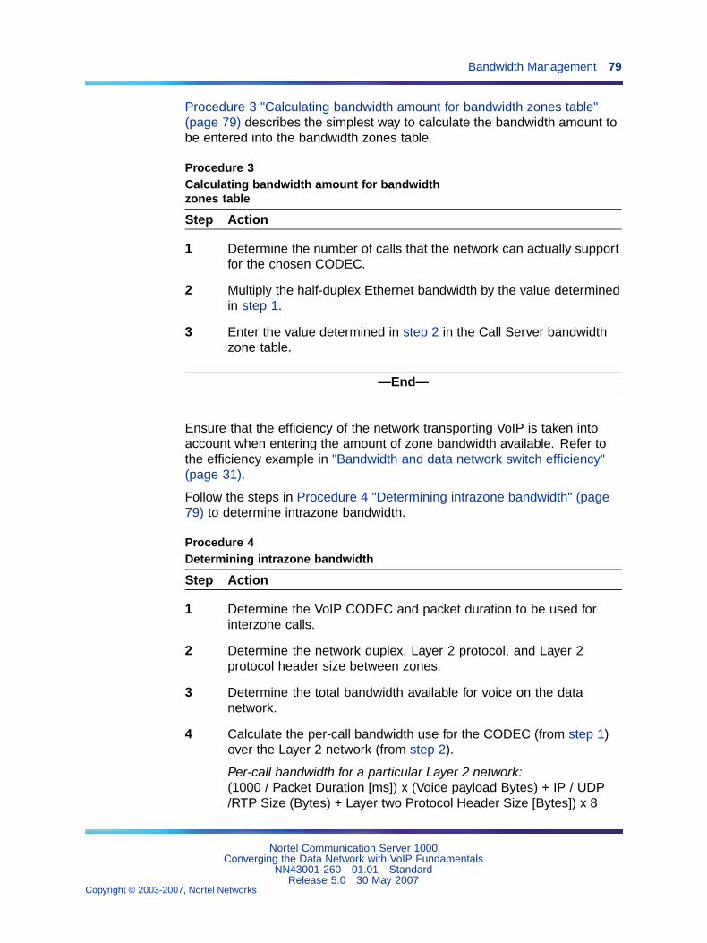
Bandwidth Management 79
Procedure 3 "Calculating bandwidth amount for bandwidth zones table"(page 79) describes the simplest way to calculate the bandwidth amount tobe entered into the bandwidth zones table.
Procedure 3Calculating bandwidth amount for bandwidthzones table
Step Action
1 Determine the number of calls that the network can actually supportfor the chosen CODEC.
2 Multiply the half-duplex Ethernet bandwidth by the value determinedin step 1.
3 Enter the value determined in step 2 in the Call Server bandwidthzone table.
—End—
Ensure that the efficiency of the network transporting VoIP is taken intoaccount when entering the amount of zone bandwidth available. Refer tothe efficiency example in "Bandwidth and data network switch efficiency"(page 31).
Follow the steps in Procedure 4 "Determining intrazone bandwidth" (page79) to determine intrazone bandwidth.
Procedure 4Determining intrazone bandwidth
Step Action
1 Determine the VoIP CODEC and packet duration to be used forinterzone calls.
2 Determine the network duplex, Layer 2 protocol, and Layer 2protocol header size between zones.
3 Determine the total bandwidth available for voice on the datanetwork.
4 Calculate the per-call bandwidth use for the CODEC (from step 1)over the Layer 2 network (from step 2).
Per-call bandwidth for a particular Layer 2 network:(1000 / Packet Duration [ms]) x (Voice payload Bytes) + IP / UDP/RTP Size (Bytes) + Layer two Protocol Header Size [Bytes]) x 8
Nortel Communication Server 1000Converging the Data Network with VoIP Fundamentals
NN43001-260 01.01 StandardRelease 5.0 30 May 2007
Copyright © 2003-2007, Nortel Networks
.
80 QoS mechanisms
Alternatively, see "VoIP Bandwidth Demand Calculator" (page 99)
5 Calculate the number of calls the network is actually capable ofhandling. To do this, divide the total bandwidth available for voiceover the Layer 2 network (from step 3) by the real per-call bandwidthuse for the CODEC (from step 4).
6 Determine the half-duplex Ethernet bandwidth for one call for theCODEC (from step 1) to be used. See Table 6 "Bandwidth estimatesused by Call Admission Control" (page 77).
7 Calculate the bandwidth value to enter into the Call Server bandwidthmanagement zone. Multiply the half-duplex Ethernet bandwidth(from step 6) by the number of calls the network is actually capableof handling.
—End—
Determination of intrazone bandwidth is not normally required. This isbecause a large amount of bandwidth is normally available within a localnetwork, so an arbitrarily large value can be entered for the interzonebandwidth available.
If required, interzone bandwidth is calculated using the same procedureas for intrazone bandwidth (see Procedure 4 "Determining intrazonebandwidth" (page 79)).
Example: Interzone bandwidth calculationBased on Bandwidth management of G.729A interzone traffic over a512-Kbps Frame Relay network, as shown in Figure 16 "Bandwidthmanagement example" (page 71), perform the following steps:
Step Action
1 CODEC = G.729A, 20ms
2 Network type = Full duplex Frame Relay with 6-byte header
3 Total bandwidth available = 512 Kbps * 0.9 = 460.8 Kbps (0.9 is anestimate of the efficiency of a random Frame Relay router. The actualefficiency may vary. See calculating data network switch efficiencyin "Bandwidth and data network switch efficiency" (page 31))
4 G.729A per-call bandwidth on a full duplex frame relay network =(1000 / 20) * (20 + 40 + 6) * 8 = 26400 bps = 26.4 Kbps
5 Total calls possible = 460.8 Kbps / 26.4 kbps = 17 calls
Nortel Communication Server 1000Converging the Data Network with VoIP Fundamentals
NN43001-260 01.01 StandardRelease 5.0 30 May 2007
Copyright © 2003-2007, Nortel Networks
.
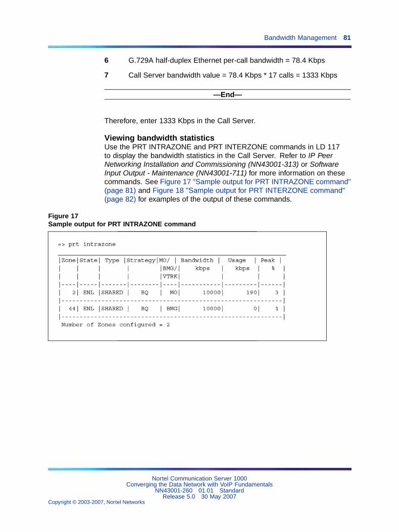
Bandwidth Management 81
6 G.729A half-duplex Ethernet per-call bandwidth = 78.4 Kbps
7 Call Server bandwidth value = 78.4 Kbps * 17 calls = 1333 Kbps
—End—
Therefore, enter 1333 Kbps in the Call Server.
Viewing bandwidth statisticsUse the PRT INTRAZONE and PRT INTERZONE commands in LD 117to display the bandwidth statistics in the Call Server. Refer to IP PeerNetworking Installation and Commissioning (NN43001-313) or SoftwareInput Output - Maintenance (NN43001-711) for more information on thesecommands. See Figure 17 "Sample output for PRT INTRAZONE command"(page 81) and Figure 18 "Sample output for PRT INTERZONE command"(page 82) for examples of the output of these commands.
Figure 17Sample output for PRT INTRAZONE command
Nortel Communication Server 1000Converging the Data Network with VoIP Fundamentals
NN43001-260 01.01 StandardRelease 5.0 30 May 2007
Copyright © 2003-2007, Nortel Networks
.
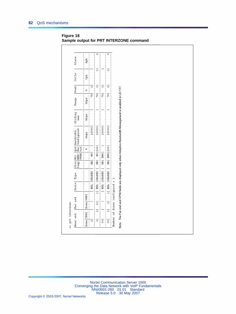
82 QoS mechanisms
Figure 18Sample output for PRT INTERZONE command
Nortel Communication Server 1000Converging the Data Network with VoIP Fundamentals
NN43001-260 01.01 StandardRelease 5.0 30 May 2007
Copyright © 2003-2007, Nortel Networks
.
83
Network performance measurement
ContentsThis section contains information on the following topics:
"Introduction" (page 84)
"Performance criteria" (page 85)
"Network performance evaluation overview" (page 86)
"Network performance measurement tools" (page 91)
"Network availability" (page 91)
"Bandwidth" (page 93)
"Available Bandwidth" (page 93)
"Guaranteed Bandwidth" (page 94)
"Queueing" (page 94)
"Calculating per-call bandwidth use" (page 94)
"Silence Suppression engineering considerations" (page 99)
"Estimate network loading caused by VoIP traffic" (page 100)
"Route Link Traffic estimation" (page 104)
"Enough capacity" (page 105)
"Insufficient link capacity" (page 106)
"Other intranet resource considerations" (page 107)
"Delay" (page 107)
"Effects of delay on voice quality" (page 109)
"Components of delay" (page 109)
"Measuring end-to-end network delay" (page 112)
"Adjusting PING statistics" (page 114)
"Other measurement considerations" (page 115)
"Reducing delays" (page 115)
"Reducing hop count" (page 116)
Nortel Communication Server 1000Converging the Data Network with VoIP Fundamentals
NN43001-260 01.01 StandardRelease 5.0 30 May 2007
Copyright © 2003-2007, Nortel Networks
.
84 Network performance measurement
"Recording routes" (page 116)
"Routing issues" (page 116)
"Jitter" (page 116)
"Jitter buffers" (page 118)
"Late packets" (page 118)
"Adjusting jitter buffer size" (page 118)
"Jitter measurement tools" (page 120)
"Packet loss" (page 120)
"Physical medium loss" (page 120)
"Congestion loss" (page 120)
"Measuring end-to-end packet loss" (page 122)
"Packet Loss Concealment" (page 122)
"Reducing packet loss" (page 123)
"Network delay and packet loss evaluation example" (page 123)
"Estimate voice quality" (page 124)
"Sample scenarios" (page 128)
"Does the intranet provide expected voice quality?" (page 129)
IntroductionTo create a VoIP-grade network, certain QoS standards for basic networkelements must be met. The following QoS parameters can be measuredand monitored to determine if desired service levels have been obtained:
• network availability
• bandwidth
• delay
• jitter
• packet loss
These QoS parameters and mechanisms affect the application’s orend-user’s Quality of Experience (QoE). These QoS parameters apply toany IP (Internet Protocol) network carrying VoIP traffic, including LANs,campus-wide networks, and WANs.
Nortel Communication Server 1000Converging the Data Network with VoIP Fundamentals
NN43001-260 01.01 StandardRelease 5.0 30 May 2007
Copyright © 2003-2007, Nortel Networks
.
Introduction 85
Performance criteriaThis section describes criteria for achieving excellent voice quality. Thenetwork should meet these specifications.
• End-to-end packet delay: Packet delay is the point-to-point, one-waydelay between the time a packet is sent to the time it is received at theremote end. It is comprised of delays at the Voice Gateway Media Card,Internet Telephone, and the IP network. To minimize delays, the IPTelephony node and Internet Telephone must be located to minimize thenumber of hops to the network backbone or WAN.
Note: Nortel recommends an end-to-end delay of <= 50 ms on theIP network to ensure good voice quality. This does not include thebuilt-in delay of the Voice Gateway Media Card and IP Phone.
• End-to-end packet loss: Packet loss is the percentage of packetssent that do not arrive at their destination. Transmission equipmentproblems, packet delay, and network congestion cause packet loss. Invoice conversation, packet loss appears as gaps in the conversation.Sporadic loss of a few packets can be more tolerable than infrequentloss of a large number of packets clustered together.
Note: For high-quality voice transmission, the long-term averagepacket loss between the IP Phones and the Voice Gateway MediaCard TLAN network interface must be < 1%, and the short-termpacket loss must not exceed 5% in any 10-second interval.
Recommendation
To achieve excellent voice quality, Nortel strongly recommends using G.711CODEC with the following configuration:
• end-to end delay less than 150 ms one way (network delay +packetization delay + jitter buffer delay < 150). See "IP expansion linkPacket Delay Variation jitter buffer" (page 163).
• packet loss less than 0.5% (approaching 0%)
• maximum jitter buffer setting for IP Phone as low as possible (maximum100 ms)
Packet loss on the ELAN network interface can cause:
— communication problems between the Call Server and the VoiceGateway Media Cards
— lost SNMP alarms
— incorrect status information on the TM console
— other signaling-related problems
Nortel Communication Server 1000Converging the Data Network with VoIP Fundamentals
NN43001-260 01.01 StandardRelease 5.0 30 May 2007
Copyright © 2003-2007, Nortel Networks
.
86 Network performance measurement
Note: Since the ELAN network is a Layer 2 Switched LAN,the packet loss must be zero. If packet loss is experienced, itssource must be investigated and eliminated. For reliable signalingcommunication on the ELAN network interface, the packet lossmust be < 1%.
Network performance evaluation overviewThere are two main objectives when dealing with the QoS issue in an IPnetwork:
1. Predict the expected QoS.
2. Evaluate the QoS after integrating VoIP traffic into the intranet.
The process for either case is similar—the first is without VoIP traffic, andthe second is with VoIP traffic. The differences are discussed in this section.
This process assumes that the PING program is available on a PC, or somenetwork management tool is available to collect delay and loss data and toaccess the LAN that connects to the router to the intranet.
Procedure 5Evaluating network performance: overview
Step Action
1 Use PING or an equivalent tool to collect round-trip delay (in ms)and loss (in%) data.
2 Divide the delay (determined in step 1) by 2 to approximate one-waydelay. Add 93 ms to adjust for ITG processing and buffering time.
3 Use a QoS chart, or Table 21 "QoS levels" (page 127), to predict theQoS categories: Excellent, Good, Fair or Poor.
4 If a customer wants to manage the QoS in a more detailed fashion,re-balance the values of delay compared to loss by adjusting systemparameters, such as preferred CODEC, payload size, and routingalgorithm, to move resulting QoS among different categories.
5 If the QoS objective is met, repeat the process periodically to makesure the required QoS is maintained.
—End—
Nortel Communication Server 1000Converging the Data Network with VoIP Fundamentals
NN43001-260 01.01 StandardRelease 5.0 30 May 2007
Copyright © 2003-2007, Nortel Networks
.

Introduction 87
Set QoS expectationsThe users of corporate voice and data services expect these services tomeet some perceived Quality of Service (QoS) which in turn influencesnetwork design. The goal is to design and allocate enough resources inthe network to meet users’ needs. QoS metrics or parameters are whatquantifies the needs of the "user" of the "service".
In the context of a Meridian 1, CS 1000S, and CS 1000M system, Figure19 "QoS parameters" (page 87) shows the relationship between users andservices.
Figure 19QoS parameters
In Figure 19 "QoS parameters" (page 87), there are two interfaces toconsider.
• The Meridian 1, including the IP Trunk 3.0 (or later) nodes, interfaceswith the end users. Voice services offered by the Meridian 1 must meetuser-oriented QoS objectives.
• The IP Trunk 3.0 (or later) nodes interface with the intranet. The serviceprovided by the intranet is "best-effort delivery of IP packets", not"guarantee QoS for real-time voice transport." IP Trunk 3.0 (or later)translates the QoS objectives set by the end-users into IP-oriented QoSobjectives. The guidelines call these objectives intranet QoS objectives.
Nortel Communication Server 1000Converging the Data Network with VoIP Fundamentals
NN43001-260 01.01 StandardRelease 5.0 30 May 2007
Copyright © 2003-2007, Nortel Networks
.
88 Network performance measurement
The QoS level is a user-oriented QoS metric which takes on one of foursettings – Excellent, Good, Fair, or Poor – indicating the quality of voiceservice. IP Trunk 3.0 (or later) periodically calculates the prevailing QoSlevel per site pair, based on its measurement of the following:
• one-way delay
• packet loss
• CODEC
Recommendation
Nortel strongly recommends that G.711 CODEC be used over high-bandwidthconnections, and used any time that call quality is the highest priority. Wherecall quality is the highest priority, sufficient bandwidth must be provided forthe VoIP application. The Best Quality (BQ) CODEC is usually chosen andconfigured as G.711 within the zone configuration (intrazone).
Use G.729 CODEC to compress voice traffic over low-bandwidth connectionswhen bandwidth considerations take precedence over call quality. The BestBandwidth (BB) CODEC is usually chosen and set to G.729A or G.729ABbetween zones (interzone).
CODEC details are then configured on the Signaling Server through TM orCS 1000 Element Manager.
Figure 20 "QoS levels with G.729A/AB CODEC" (page 89), Figure 21 "QoSlevel with G.711 CODEC" (page 90), and Figure 22 "QoS level with G.723CODEC" (page 90) are derived from the ITU-T G.107 Transmission RatingModel. These diagrams show the operating regions in terms of one-waydelay and packet loss for each CODEC. Note that among the CODECs,G.711 A-law/G.711 mu-law delivers the best quality for a given intranetQoS, followed by G.729AB, G.723.1 6.4 kbps, and G.723.1 5.3 kbps. Thesegraphs determine the delay and error budget for the underlying intranet so itdelivers a required quality of voice service.
Fax is more susceptible to packet loss than is the human ear, in that qualitystarts to degrade when packet loss exceeds 4%. Nortel recommends thatfax services be supported with IP Trunk 3.0 (or later) operating at theExcellent or Good QoS level. Avoid offering fax services between two sitesthat can guarantee no better than a Fair or Poor QoS level.
G.729AB CODECThe G.729 uses less bandwidth than the G.711. If minimizing bandwidthdemand is a priority, and the customer is willing to accept lesser voicequality, a G.729AB CODEC can be used.
Nortel Communication Server 1000Converging the Data Network with VoIP Fundamentals
NN43001-260 01.01 StandardRelease 5.0 30 May 2007
Copyright © 2003-2007, Nortel Networks
.
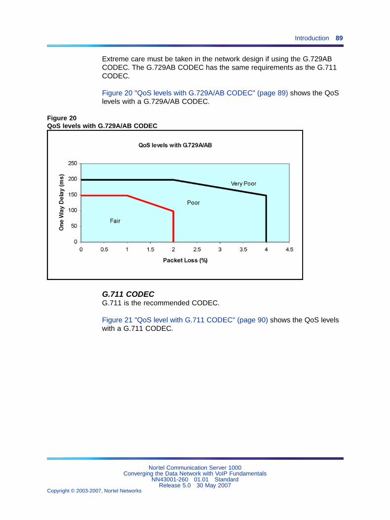
Introduction 89
Extreme care must be taken in the network design if using the G.729ABCODEC. The G.729AB CODEC has the same requirements as the G.711CODEC.
Figure 20 "QoS levels with G.729A/AB CODEC" (page 89) shows the QoSlevels with a G.729A/AB CODEC.
Figure 20QoS levels with G.729A/AB CODEC
G.711 CODECG.711 is the recommended CODEC.
Figure 21 "QoS level with G.711 CODEC" (page 90) shows the QoS levelswith a G.711 CODEC.
Nortel Communication Server 1000Converging the Data Network with VoIP Fundamentals
NN43001-260 01.01 StandardRelease 5.0 30 May 2007
Copyright © 2003-2007, Nortel Networks
.
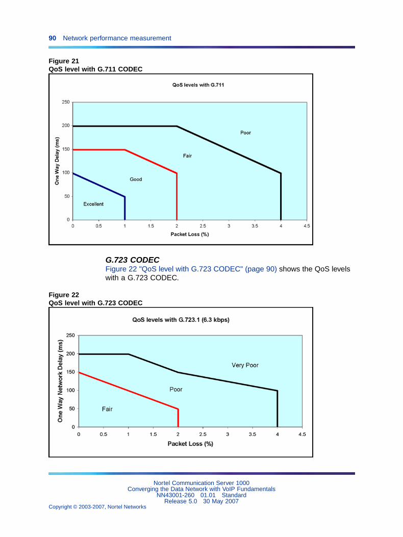
90 Network performance measurement
Figure 21QoS level with G.711 CODEC
G.723 CODECFigure 22 "QoS level with G.723 CODEC" (page 90) shows the QoS levelswith a G.723 CODEC.
Figure 22QoS level with G.723 CODEC
Nortel Communication Server 1000Converging the Data Network with VoIP Fundamentals
NN43001-260 01.01 StandardRelease 5.0 30 May 2007
Copyright © 2003-2007, Nortel Networks
.
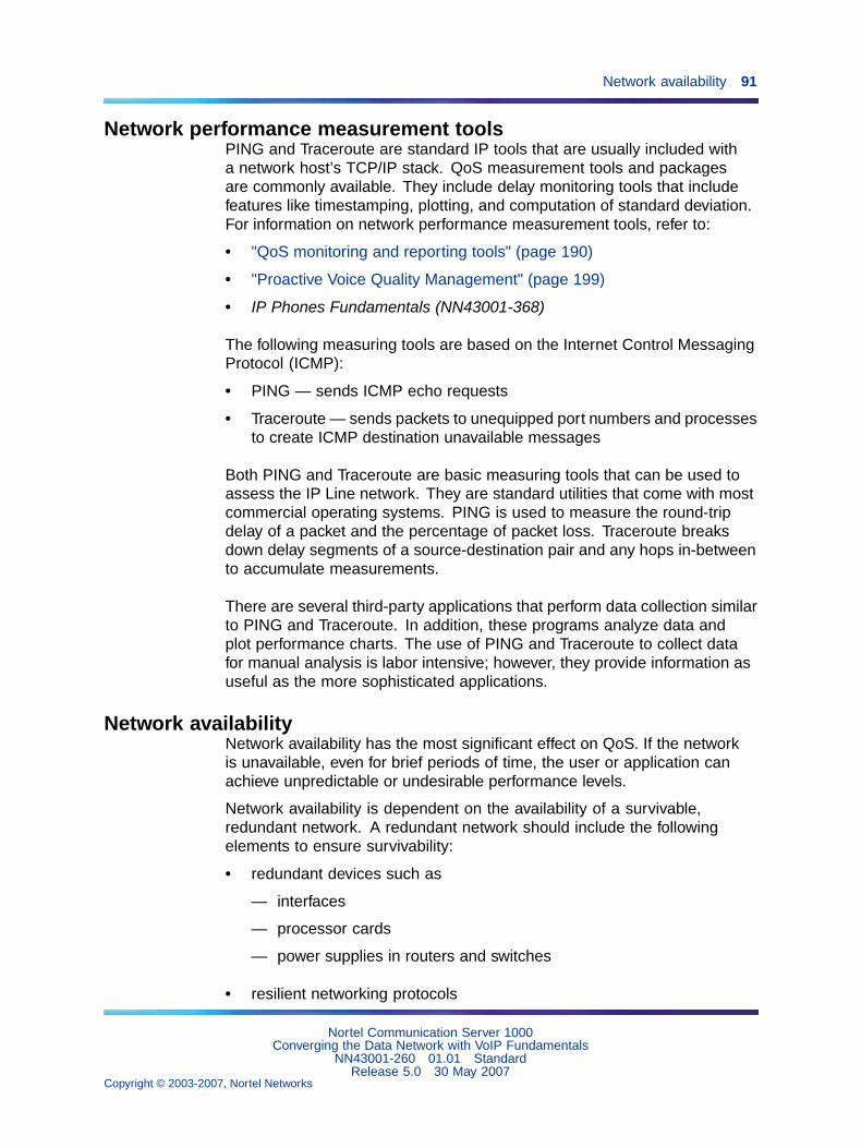
Network availability 91
Network performance measurement toolsPING and Traceroute are standard IP tools that are usually included witha network host’s TCP/IP stack. QoS measurement tools and packagesare commonly available. They include delay monitoring tools that includefeatures like timestamping, plotting, and computation of standard deviation.For information on network performance measurement tools, refer to:
• "QoS monitoring and reporting tools" (page 190)
• "Proactive Voice Quality Management" (page 199)
• IP Phones Fundamentals (NN43001-368)
The following measuring tools are based on the Internet Control MessagingProtocol (ICMP):
• PING — sends ICMP echo requests
• Traceroute — sends packets to unequipped port numbers and processesto create ICMP destination unavailable messages
Both PING and Traceroute are basic measuring tools that can be used toassess the IP Line network. They are standard utilities that come with mostcommercial operating systems. PING is used to measure the round-tripdelay of a packet and the percentage of packet loss. Traceroute breaksdown delay segments of a source-destination pair and any hops in-betweento accumulate measurements.
There are several third-party applications that perform data collection similarto PING and Traceroute. In addition, these programs analyze data andplot performance charts. The use of PING and Traceroute to collect datafor manual analysis is labor intensive; however, they provide information asuseful as the more sophisticated applications.
Network availabilityNetwork availability has the most significant effect on QoS. If the networkis unavailable, even for brief periods of time, the user or application canachieve unpredictable or undesirable performance levels.
Network availability is dependent on the availability of a survivable,redundant network. A redundant network should include the followingelements to ensure survivability:
• redundant devices such as
— interfaces
— processor cards
— power supplies in routers and switches
• resilient networking protocols
Nortel Communication Server 1000Converging the Data Network with VoIP Fundamentals
NN43001-260 01.01 StandardRelease 5.0 30 May 2007
Copyright © 2003-2007, Nortel Networks
.
92 Network performance measurement
• multiple physical connections, such as copper or fiber
• backup power sources
Network availability has the most significant effect on QoS. If the networkis unavailable, even for brief periods of time, the user or application canachieve unpredictable or undesirable performance levels.
It is necessary to engineer a survivable network to provide guaranteednetwork availability.
Media SecurityMedia Security enables two endpoints capable of Secure Real-TimeTransport Protocol (SRTP) connections to engage in secure mediaexchanges. For calls that pass over IP systems only, Media Security canprovide end-to-end encryption of the call if both endpoints are capable ofsupporting SRTP connections. If you configure Media Security to use theMedia Security Always class of service, it blocks any calls that cannot beencrypted.
When you assess the reliability of the network, be aware that the MediaSecurity feature, if configured to use the Media Security Always class ofservice, can block a call if any of the following is true:
• One of the telephones in the call is an IP Phone registered on the sameCall Server as the other endpoint, but does not support media security.
• One of the telephones in the call is a non-IP phone on the same CallServer as the other endpoint, but a Voice Gateway TN resource thatsupports SRTP is not available.
• One of the telephones in the call is configured to use the Media SecurityAlways class of service, and the trunk is an H.323 trunk or a SIP(Session Initiation Protocol) trunk that is configured to use the MediaSecurity Never class of service.
• One of the telephones in the call is configured to use the Media SecurityAlways class of service, and the far end is an IP Phone, media gateway,or media server that does not support media security or is incompatiblewith the SRTP key exchange protocol that is used by CS 1000 SIPVTRK (Virtual Trunk) Gateway.
Nortel Communication Server 1000Converging the Data Network with VoIP Fundamentals
NN43001-260 01.01 StandardRelease 5.0 30 May 2007
Copyright © 2003-2007, Nortel Networks
.
Bandwidth 93
You can use the Traffic Reports available in LD 2 to determine the causeof a call failure if you suspect Media Security is blocking calls, as shown inTable 7 "Traffic reports for blocked calls " (page 93).
Table 7Traffic reports for blocked calls
Counter Meaning Description
cfnp Calls failed due to near endpolicy.
A high value for this counter indicates that callattempts are being made between MSAW (MediaSecurity Always) and MSNV (Media SecurityNever) types of devices.
cfnr Calls failed due to near endresources.
This counter indicates the number of calls that failbecause secure DSPs (Digital Signal Processors)are not available.
For more information about Traffic Reports in LD 2, see Traffic Measurement:Formats and Output Reference (NN43001-750). If you suspect calls arebeing blocked because of Media Security policy restrictions imposed by yoursystem security administrator, contact the security administrator responsiblefor Media Security configuration policies on your system.
For more information about Media Security, including furtherrecommendations about configuration, see Security ManagementFundamentals (NN43001-604).
BandwidthBandwidth is the most significant parameter that affects QoS. There are twotypes of bandwidth:
• Available Bandwidth
• Guaranteed Bandwidth
ATTENTIONIMPORTANT!The use of QoS mechanisms that prioritize voice over data traffic effectivelyincreases the amount of bandwidth available to voice traffic.
Available BandwidthMany network operators oversubscribe the bandwidth on their network tomaximize the return on their network infrastructure or leased bandwidth.
Oversubscribing bandwidth means that the bandwidth a user subscribesto is not always available. All users compete for Available Bandwidth. Theamount of bandwidth available to a user depends on the amount of trafficfrom other network users at any given time.
Nortel Communication Server 1000Converging the Data Network with VoIP Fundamentals
NN43001-260 01.01 StandardRelease 5.0 30 May 2007
Copyright © 2003-2007, Nortel Networks
.
94 Network performance measurement
Guaranteed BandwidthSome network operators offer a service that guarantees a minimumbandwidth and burst bandwidth in the Service Level Agreement (SLA).This service is more expensive than the Available Bandwidth service. Thenetwork operator must ensure that the Guaranteed Bandwidth subscribersget preferential treatment (QoS bandwidth guarantee) over the AvailableBandwidth subscribers.
This can be accomplished in several ways. Sometimes, the networkoperator separates the subscribers by different physical or logical networks,such as Virtual Local Area Networks (VLANs) or Virtual Circuits.
In other cases, the Guaranteed Bandwidth traffic shares the sameinfrastructure as the Available Bandwidth traffic. This is often seen wherenetwork connections are expensive, or where the bandwidth is leased fromother service providers. When both types of subscribers share the sameinfrastructure, the network must prioritize Guaranteed Bandwidth traffic overAvailable Bandwidth traffic. This ensures that when network traffic is heavy,the Guaranteed Bandwidth subscriber’s SLA is met.
QueueingOver-engineering network bandwidth does not necessarily solve voicequality problems, as IP network traffic is inherently bursty in nature. Atany time, a burst of packets can enter a switch. If the number of packetsreceived in that instant is greater than the capacity of the transmitting port’squeue, then packets are lost. This situation is particularly serious on slowconnections.
If a queue is busy (though not necessarily full), voice packet traffic canback up and jitter can occur if voice packets are not prioritized. NetworkQoS mechanisms are based on assigning different priorities to multiplequeues. A voice queue is assigned a higher priority. If a specific queue isassigned only to voice traffic, then there is less chance that voice packetswill be discarded because the queue is too full. Network delay is reduced,as voice packets are transmitted first. This minimizes delay, jitter, and loss.Perceived voice quality is greatly improved.
Calculating per-call bandwidth useCalculating VoIP traffic requirementsIt is necessary to forecast the hundreds of call seconds for each hour (CCS)of traffic that the CS 1000 and Meridian 1 systems processes through the IPLine network. CCS traffic generated by an IP Phone is similar to that of adigital telephone. The procedures in the section calculate the bandwidthrequired to support given amounts of traffic.
Nortel Communication Server 1000Converging the Data Network with VoIP Fundamentals
NN43001-260 01.01 StandardRelease 5.0 30 May 2007
Copyright © 2003-2007, Nortel Networks
.
Bandwidth 95
The procedures require the:
• CCS/CCS rating of IP Phone
For more information, refer to Communication Server 1000M andMeridian 1 Large System Planning and Engineering (NN43021-220).
• number of IP Phones
• number of subnets/servers accessed by the IP Phones
Note: Base all traffic data on busy hour requirements.
The result of the calculation provides estimated values of the followingrequirements:
• total LAN bandwidth requirement
• WAN bandwidth requirement for each subnet or server/router
It is necessary to consider the impact of incremental IP Line traffic onrouters and LAN resources in the intranet. LAN segments can becomesaturated, and routers can experience high CPU use. Consider re-routingscenarios in a case where a link is down.
Calculating LAN trafficTo calculate the total LAN requirement, total all sources of traffic destinedfor the Internet Telephony network using the same LAN. The data rate fora LAN is the total bit rate. The total subnet traffic is measured in Erlangs.An Erlang is a telecommunications traffic measurement unit used todescribe the total traffic volume of one hour. Network designers use thesemeasurements to track network traffic patterns.
Follow the steps in Procedure 6 "Calculating LAN traffic" (page 95) tocalculate the LAN traffic.
Procedure 6Calculating LAN traffic
Step Action
1 Add the following to calculate total subnet traffic (in Erlangs):
• number of IP Phones x (CCS ÷ CCS rating)
• voice gateways on Voice Gateway Media Card
• WAN connection
Note: Each source of traffic has a different CCS rating.Calculate the subnet traffic for each source of traffic and addthe amounts to get the total.
Nortel Communication Server 1000Converging the Data Network with VoIP Fundamentals
NN43001-260 01.01 StandardRelease 5.0 30 May 2007
Copyright © 2003-2007, Nortel Networks
.
96 Network performance measurement
2 Use the number of Erlangs to calculate the equivalent number oflines by using the calculator at the following website:
http://www.erlang.com/calculator/erlb
Assume a blocking factor of 1% (0.010).
3 Find the LAN bandwidth usage (Kbps) in Table 6 "Bandwidthestimates used by Call Admission Control" (page 77), based on theCODEC used for the traffic source.
4 Calculate the bandwidth of a subnet using the following calculation:
Subnet bandwidth = Total number of lines × LAN bandwidth usage
5 Repeat Step 1 to Step 4 for each subnet.
6 Calculate the total LAN traffic by adding the total bandwidth for eachsubnet calculation.
—End—
LAN engineering exampleThe following is an example of calculating LAN bandwidth assuminghalf-duplex links.
Using G.729AB 30 ms, LAN bandwidth usage is 57.6 Kbps.
The formula is:
Number of Erlangs = Number of IP Phones × (CCS ÷ 36)
Step Action
1 Subnet A: 28 Internet Telephones, average 6 CCS ÷ IP Phone
Subnet A total Erlangs = 28 × 6 ÷ 36 = 4.66Subnet A bandwidth = 4.66 × 57.6Kbps = 268.4 Kbps
2 Subnet B: 72 IP Phones, average 5 CCS ÷ Internet Telephone
Subnet B total Erlangs = 72 × 5 ÷ 36 = 10Subnet B bandwidth = 10 × 57.6 = 576 Kbps
3 Subnet C: 12 IP Phones, average 6 CCS ÷ IP Phone
Subnet C total Erlangs = 12 × 6 ÷ 36 = 2Subnet C bandwidth = 2 × 57.6 = 115.2 Kbps
4 Calculate the LAN Bandwidth by finding the sum of all subnetbandwidths:
LAN Bandwidth = 268.4 + 576 + 115.2 = 959.6 Kbps
Nortel Communication Server 1000Converging the Data Network with VoIP Fundamentals
NN43001-260 01.01 StandardRelease 5.0 30 May 2007
Copyright © 2003-2007, Nortel Networks
.
Bandwidth 97
—End—
WAN traffic calculationsFor data rate requirements for the intranet route, calculation is based onduplex channels. The data rate for a WAN is the duplex data rate. Forexample, 128 Kbps on the LAN is equal to a 64 Kbps duplex channel onthe WAN. Use the following procedure to calculate data rate requirementsfor the intranet route. The effects of Real-time Transport Protocol (RTP)header compression by the router are not considered in these calculationsbut must be included where applicable.
Follow the steps in Procedure 7 "Calculating WAN traffic" (page 97) tocalculate WAN traffic.
Procedure 7Calculating WAN traffic
Step Action
1 Calculate the total subnet traffic using the following formula:
Total subnet traffic = Number of IP Phones x CCS/InternetTelephone.
2 Convert to Erlangs:
Total CCS / 36 (on the half-duplex LAN)
3 Find WAN bandwidth usage (Kbps) from the "WAN Base Bandwidth"columns of Table 6 "Bandwidth estimates used by Call AdmissionControl" (page 77).
4 Calculate bandwidth for each subnet = Total Erlangs x WANbandwidth usage.
5 Multiply bandwidth of each subnet by 1.3 to adjust for traffic peaking.
6 Repeat the procedure for each subnet.
7 Adjust WAN bandwidth to account for WAN overhead dependingon the WAN technology used:
• ATM (AAL1): multiply subnet bandwidth x 1.20 (9 bytesoverhead/44 bytes payload)
• ATM (AAL5): multiply subnet bandwidth x 1.13 (6 bytesoverhead/47 bytes payload)
• Frame Relay: multiply subnet bandwidth x 1.20 (6 bytesoverhead/30 bytes payload – variable payload up to 4096 bytes)
Nortel Communication Server 1000Converging the Data Network with VoIP Fundamentals
NN43001-260 01.01 StandardRelease 5.0 30 May 2007
Copyright © 2003-2007, Nortel Networks
.
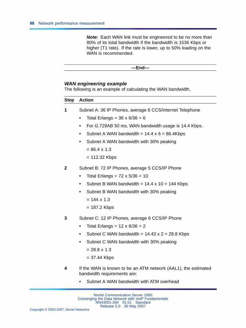
98 Network performance measurement
Note: Each WAN link must be engineered to be no more than80% of its total bandwidth if the bandwidth is 1536 Kbps orhigher (T1 rate). If the rate is lower, up to 50% loading on theWAN is recommended.
—End—
WAN engineering exampleThe following is an example of calculating the WAN bandwidth.
Step Action
1 Subnet A: 36 IP Phones, average 6 CCS/Internet Telephone
• Total Erlangs = 36 x 6/36 = 6
• For G.729AB 50 ms, WAN bandwidth usage is 14.4 Kbps.
• Subnet A WAN bandwidth = 14.4 x 6 = 86.4Kbps
• Subnet A WAN bandwidth with 30% peaking
= 86.4 x 1.3
= 112.32 Kbps
2 Subnet B: 72 IP Phones, average 5 CCS/IP Phone
• Total Erlangs = 72 x 5/36 = 10
• Subnet B WAN bandwidth = 14.4 x 10 = 144 Kbps
• Subnet B WAN bandwidth with 30% peaking
= 144 x 1.3
= 187.2 Kbps
3 Subnet C: 12 IP Phones, average 6 CCS/IP Phone
• Total Erlangs = 12 x 6/36 = 2
• Subnet C WAN bandwidth = 14.43 x 2 = 28.8 Kbps
• Subnet C WAN bandwidth with 30% peaking
= 28.8 x 1.3
= 37.44 Kbps
4 If the WAN is known to be an ATM network (AAL1), the estimatedbandwidth requirements are:
• Subnet A WAN bandwidth with ATM overhead
Nortel Communication Server 1000Converging the Data Network with VoIP Fundamentals
NN43001-260 01.01 StandardRelease 5.0 30 May 2007
Copyright © 2003-2007, Nortel Networks
.
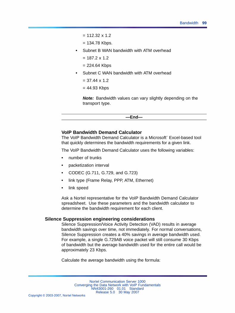
Bandwidth 99
= 112.32 x 1.2
= 134.78 Kbps.
• Subnet B WAN bandwidth with ATM overhead
= 187.2 x 1.2
= 224.64 Kbps
• Subnet C WAN bandwidth with ATM overhead
= 37.44 x 1.2
= 44.93 Kbps
Note: Bandwidth values can vary slightly depending on thetransport type.
—End—
VoIP Bandwidth Demand CalculatorThe VoIP Bandwidth Demand Calculator is a Microsoft E¨ xcel-based toolthat quickly determines the bandwidth requirements for a given link.
The VoIP Bandwidth Demand Calculator uses the following variables:
• number of trunks
• packetization interval
• CODEC (G.711, G.729, and G.723)
• link type (Frame Relay, PPP, ATM, Ethernet)
• link speed
Ask a Nortel representative for the VoIP Bandwidth Demand Calculatorspreadsheet. Use these parameters and the bandwidth calculator todetermine the bandwidth requirement for each client.
Silence Suppression engineering considerationsSilence Suppression/Voice Activity Detection (VAD) results in averagebandwidth savings over time, not immediately. For normal conversations,Silence Suppression creates a 40% savings in average bandwidth used.For example, a single G.729AB voice packet will still consume 30 Kbpsof bandwidth but the average bandwidth used for the entire call would beapproximately 23 Kbps.
Calculate the average bandwidth using the formula:
Nortel Communication Server 1000Converging the Data Network with VoIP Fundamentals
NN43001-260 01.01 StandardRelease 5.0 30 May 2007
Copyright © 2003-2007, Nortel Networks
.
100 Network performance measurement
CODEC bandwidth from Table 6 "Bandwidth estimates used by CallAdmission Control" (page 77) x 0.6
When voice services with multi-channel requirements are extensively usedin an VoIP network, such as Conference, Music-on-hold, and MessageBroadcasting, additional voice traffic peaks to the IP network are generateddue to the simultaneous voice-traffic bursts on multiple channels on thesame links.
Estimate network loading caused by VoIP trafficAn efficient VoIP network design requires an understanding of traffic andthe underlying network that carries the traffic. To determine the networkrequirements of the specific system, the technician must perform the stepsin Procedure 8 "Determining network requirements – overview" (page 100).
Before bandwidth estimation can begin, obtain the following network data:
• A network topology and routing diagram.
• A list of the sites where the CS 1000 Release 4.5 nodes are to beinstalled.
• List the sites with VoIP traffic, and the CODEC and frame duration(payload) to be used.
• Obtain the offered traffic in CCS for each site pair; if available, separatevoice traffic from fax traffic (fax traffic sent and received).
• In a network with multiple time zones, use the same real-time busy hourvarying actual clock hours) at each site that yields the highest overallnetwork traffic. Traffic to a route is the sum of voice traffic plus the largerof one-way fax traffic either sent or received.
Procedure 8Determining network requirements: overview
Step Action
1 Estimate the amount of traffic processed by the Meridian 1 or CS1000 system through the IP Line network.
See Communication Server 1000M and Meridian 1: Large SystemPlanning and Engineering (NN43021-220) .
2 Assess if the existing corporate intranet can adequately supportvoice services.
See "Network design assessment" (page 25).
3 Organize the IP Line network into "zones" representing differenttopographical areas of the network that are separated according tobandwidth considerations.
Nortel Communication Server 1000Converging the Data Network with VoIP Fundamentals
NN43001-260 01.01 StandardRelease 5.0 30 May 2007
Copyright © 2003-2007, Nortel Networks
.
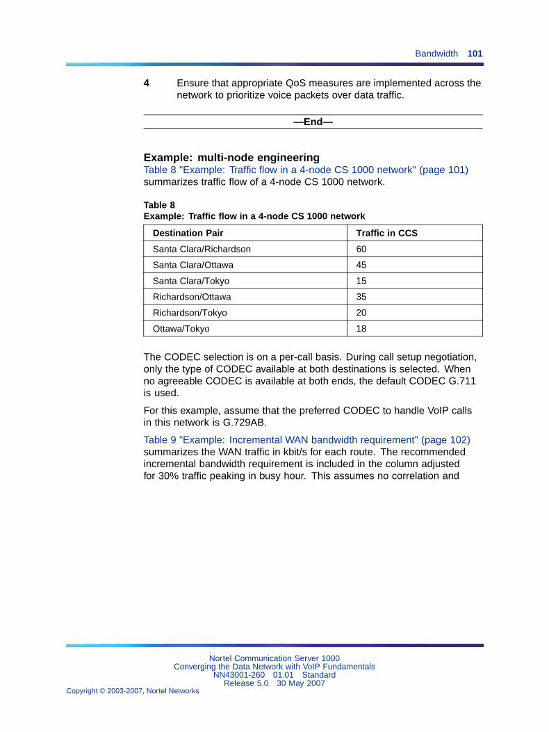
Bandwidth 101
4 Ensure that appropriate QoS measures are implemented across thenetwork to prioritize voice packets over data traffic.
—End—
Example: multi-node engineeringTable 8 "Example: Traffic flow in a 4-node CS 1000 network" (page 101)summarizes traffic flow of a 4-node CS 1000 network.
Table 8Example: Traffic flow in a 4-node CS 1000 network
Destination Pair Traffic in CCS
Santa Clara/Richardson 60
Santa Clara/Ottawa 45
Santa Clara/Tokyo 15
Richardson/Ottawa 35
Richardson/Tokyo 20
Ottawa/Tokyo 18
The CODEC selection is on a per-call basis. During call setup negotiation,only the type of CODEC available at both destinations is selected. Whenno agreeable CODEC is available at both ends, the default CODEC G.711is used.
For this example, assume that the preferred CODEC to handle VoIP callsin this network is G.729AB.
Table 9 "Example: Incremental WAN bandwidth requirement" (page 102)summarizes the WAN traffic in kbit/s for each route. The recommendedincremental bandwidth requirement is included in the column adjustedfor 30% traffic peaking in busy hour. This assumes no correlation and
Nortel Communication Server 1000Converging the Data Network with VoIP Fundamentals
NN43001-260 01.01 StandardRelease 5.0 30 May 2007
Copyright © 2003-2007, Nortel Networks
.
102 Network performance measurement
no synchronization of voice bursts in different simultaneous calls. Thisassumes some statistical model of granularity and distribution of voicemessage bursts due to Silence Suppression.
Table 9Example: Incremental WAN bandwidth requirement
Destination PairCCS on
WAN
WANtraffic in
kbit/s
Peaked WANtraffic (x1.3)
inkbit/s
Santa Clara/Richardson 60 18.7 24.3
Santa Clara/Ottawa 45 14.0 18.2
Santa Clara/Tokyo 15 4.7 6.1
Richardson/Ottawa 35 10.9 14.2
Richardson/Tokyo 20 6.2 8.1
Ottawa/Tokyo 18 5.6 7.3
The Santa Clara/Richardson information is calculated as follows:
• The total traffic on this route is 60 CCS. To use the preferred CODEC ofG.729AB with a 30 ms payload, the bandwidth on the WAN is 11.2 kbit/s.
• WAN traffic is calculated by: (60/36)*11.2 = 18.7 kbit/s.
• Increasing this number by 30% gives a peak traffic rate of 24.3 kbit/s.This is the incremental bandwidth required between Santa Clara andRichardson to carry the 60 CCS voice traffic during the busy hour.
Assume that 20 CCS of the 60 CCS between Santa Clara and Richardsonis fax traffic. Of the 20 CCS, 14 CCS is from Santa Clara to Richardson,and 6 CCS is from Richardson to Santa Clara. What is the WAN data raterequired between those two locations?
• Traffic between the two sites can be broken down to 54 CCS from SantaClara to Richardson, and 46 CCS from Richardson to Santa Clara, withthe voice traffic 40 CCS (60 – 20) being the two-way traffic.
• The bandwidth requirement calculation would be:
(40/36)*11.2 + (14/36)*33.6 = 25.51 kbit/s
Where 14 CCS is the larger of two fax traffic parcels (14 CCS vs. 6 CCS).
• After adjusting for peaking, the incremental data rate on the WAN forthis route is 33.2 kbit/s.
• Comparing this number with 24.3 kbit/s when all 60 CCS is voice traffic,it appears that the reduction in CCS due to one-way fax traffic (20 CCS
Nortel Communication Server 1000Converging the Data Network with VoIP Fundamentals
NN43001-260 01.01 StandardRelease 5.0 30 May 2007
Copyright © 2003-2007, Nortel Networks
.
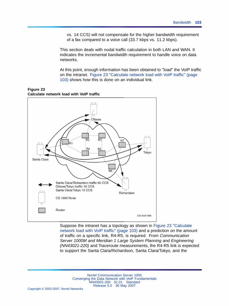
Bandwidth 103
vs. 14 CCS) will not compensate for the higher bandwidth requirementof a fax compared to a voice call (33.7 kbps vs. 11.2 kbps).
This section deals with nodal traffic calculation in both LAN and WAN. Itindicates the incremental bandwidth requirement to handle voice on datanetworks.
At this point, enough information has been obtained to "load" the VoIP trafficon the intranet. Figure 23 "Calculate network load with VoIP traffic" (page103) shows how this is done on an individual link.
Figure 23Calculate network load with VoIP traffic
Suppose the intranet has a topology as shown in Figure 23 "Calculatenetwork load with VoIP traffic" (page 103) and a prediction on the amountof traffic on a specific link, R4-R5, is required. From CommunicationServer 1000M and Meridian 1 Large System Planning and Engineering(NN43021-220) and Traceroute measurements, the R4-R5 link is expectedto support the Santa Clara/Richardson, Santa Clara/Tokyo, and the
Nortel Communication Server 1000Converging the Data Network with VoIP Fundamentals
NN43001-260 01.01 StandardRelease 5.0 30 May 2007
Copyright © 2003-2007, Nortel Networks
.
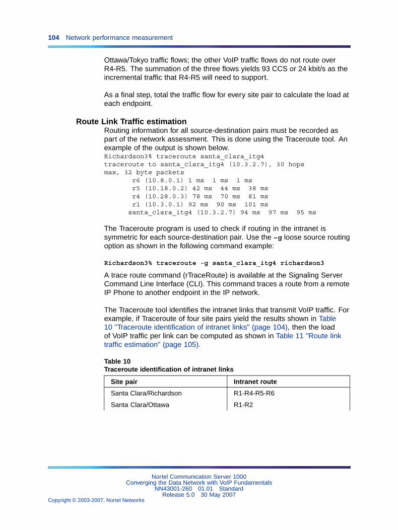
104 Network performance measurement
Ottawa/Tokyo traffic flows; the other VoIP traffic flows do not route overR4-R5. The summation of the three flows yields 93 CCS or 24 kbit/s as theincremental traffic that R4-R5 will need to support.
As a final step, total the traffic flow for every site pair to calculate the load ateach endpoint.
Route Link Traffic estimationRouting information for all source-destination pairs must be recorded aspart of the network assessment. This is done using the Traceroute tool. Anexample of the output is shown below.Richardson3% traceroute santa_clara_itg4traceroute to santa_clara_itg4 (10.3.2.7), 30 hopsmax, 32 byte packets
r6 (10.8.0.1) 1 ms 1 ms 1 msr5 (10.18.0.2) 42 ms 44 ms 38 msr4 (10.28.0.3) 78 ms 70 ms 81 msr1 (10.3.0.1) 92 ms 90 ms 101 ms
santa_clara_itg4 (10.3.2.7) 94 ms 97 ms 95 ms
The Traceroute program is used to check if routing in the intranet issymmetric for each source-destination pair. Use the –g loose source routingoption as shown in the following command example:
Richardson3% traceroute -g santa_clara_itg4 richardson3
A trace route command (rTraceRoute) is available at the Signaling ServerCommand Line Interface (CLI). This command traces a route from a remoteIP Phone to another endpoint in the IP network.
The Traceroute tool identifies the intranet links that transmit VoIP traffic. Forexample, if Traceroute of four site pairs yield the results shown in Table10 "Traceroute identification of intranet links" (page 104), then the loadof VoIP traffic per link can be computed as shown in Table 11 "Route linktraffic estimation" (page 105).
Table 10Traceroute identification of intranet links
Site pair Intranet route
Santa Clara/Richardson R1-R4-R5-R6
Santa Clara/Ottawa R1-R2
Nortel Communication Server 1000Converging the Data Network with VoIP Fundamentals
NN43001-260 01.01 StandardRelease 5.0 30 May 2007
Copyright © 2003-2007, Nortel Networks
.
Bandwidth 105
Site pair Intranet route
Santa Clara/Tokyo R1-R4-R5-R7
Richardson/Ottawa R2-R3-R5-R6
Table 11Route link traffic estimation
Links Traffic from:
R1-R4 Santa Clara/Richardson
+Santa Clara/Tokyo + Ottawa/Tokyo
R4-R5 Santa Clara/Richardson
+Santa Clara/Tokyo + Ottawa/Tokyo
R5-R6 Santa Clara/Richardson
+Richardson/Ottawa
R1-R2 Santa Clara/Ottawa + Tokyo/Ottawa
R5-R7 Santa Clara/Tokyo + Ottawa/Tokyo
R2-R3 Richardson/Ottawa
R3-R5 Richardson/Ottawa
Enough capacityFor each link, Table 12 "Computation of link capacity as compared to ITGload" (page 105) compares the available link capacity to the additional IPTrunk 3.0 (or later) load. For example, on link R4-R5, there is enoughavailable capacity (492 kbit/s) to accommodate the additional 24 kbit/s ofVoIP traffic.
Table 12Computation of link capacity as compared to ITG load
Link Utilization (%)
IncrementalIP Trunk 3.0 (or
later) load
EndCapac
ity Threshold Used
Available
capacity(kbit/s) Site pair Traffic
Sufficientcapacity?
Nortel Communication Server 1000Converging the Data Network with VoIP Fundamentals
NN43001-260 01.01 StandardRelease 5.0 30 May 2007
Copyright © 2003-2007, Nortel Networks
.
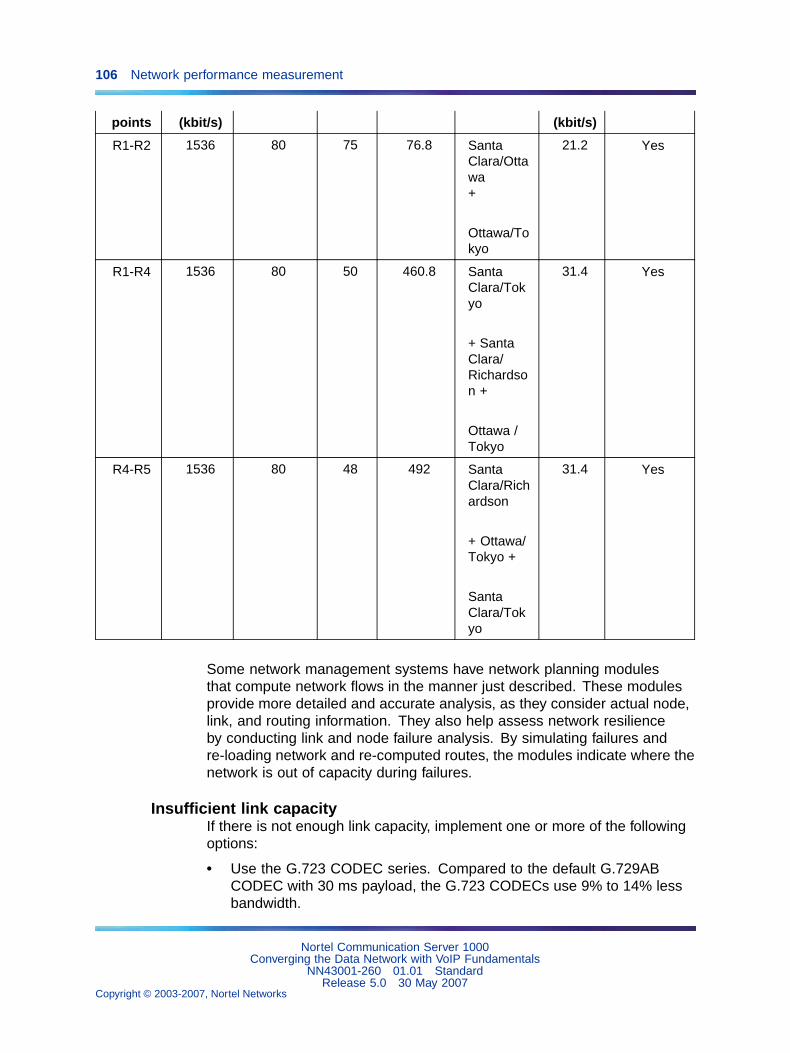
106 Network performance measurement
points (kbit/s) (kbit/s)
R1-R2 1536 80 75 76.8 SantaClara/Ottawa+
Ottawa/Tokyo
21.2 Yes
R1-R4 1536 80 50 460.8 SantaClara/Tokyo
+ SantaClara/Richardson +
Ottawa /Tokyo
31.4 Yes
R4-R5 1536 80 48 492 SantaClara/Richardson
+ Ottawa/Tokyo +
SantaClara/Tokyo
31.4 Yes
Some network management systems have network planning modulesthat compute network flows in the manner just described. These modulesprovide more detailed and accurate analysis, as they consider actual node,link, and routing information. They also help assess network resilienceby conducting link and node failure analysis. By simulating failures andre-loading network and re-computed routes, the modules indicate where thenetwork is out of capacity during failures.
Insufficient link capacityIf there is not enough link capacity, implement one or more of the followingoptions:
• Use the G.723 CODEC series. Compared to the default G.729ABCODEC with 30 ms payload, the G.723 CODECs use 9% to 14% lessbandwidth.
Nortel Communication Server 1000Converging the Data Network with VoIP Fundamentals
NN43001-260 01.01 StandardRelease 5.0 30 May 2007
Copyright © 2003-2007, Nortel Networks
.
Delay 107
• Upgrade the link’s bandwidth.
Other intranet resource considerationsBottlenecks caused by non-WAN resources are less frequent. For a morecomplete assessment, consider the impact of incremental VoIP traffic onrouters and LAN resources in the intranet. Perhaps the VoIP traffic istraversing LAN segments that are saturated, or traversing routers whoseCPU utilization is high.
DelayDelay is defined as the amount of time required for an application’s data toreach its intended destination. Delay causes significant QoE issues withvoice and video applications. Other applications, such as Fax transmissions,excessive delay causes the application to time-out and fail.
Some applications can compensate for specified amounts of delay, but oncethat amount is exceeded, QoS is compromised. VoIP and gateways alsoprovide delay compensation by using local buffering.
Delay can be fixed or variable. Variable delay is also known as jitter.
Some contributions to fixed (baseline) delay are as follows:
• Application-based delay, such as:
— voice CODEC processing
— jitter buffer delay
• Serialization delay — Delay of the voice packet at each hop of thephysical network; depends on link speed (a fixed, constant value foreach link).
• Propagation delay — Delay caused by the finite speed at whichelectronic signals can travel through a transmission medium.
In VoIP, end-to-end delay on a call is the total time elapsed from speakinginto an transmitter at one end to hearing the reconstructed sound on areceiver at the other end. Delay has a significant impact on the quality ofa voice call. Most listeners can detect delay greater than 100 ms. Delaybecomes annoying at the following levels:
• for G.711 CODEC, 250 ms
• for G.729AB CODEC, 150 ms
Figure 24 "Sources of packet delay" (page 108) shows the sources ofpacket delay.
Nortel Communication Server 1000Converging the Data Network with VoIP Fundamentals
NN43001-260 01.01 StandardRelease 5.0 30 May 2007
Copyright © 2003-2007, Nortel Networks
.
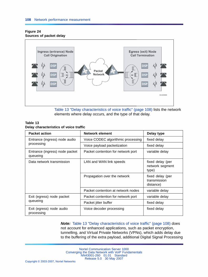
108 Network performance measurement
Figure 24Sources of packet delay
Table 13 "Delay characteristics of voice traffic" (page 108) lists the networkelements where delay occurs, and the type of that delay.
Table 13Delay characteristics of voice traffic
Packet action Network element Delay type
Voice CODEC algorithmic processing fixed delayEntrance (ingress) node audioprocessing Voice payload packetization fixed delay
Entrance (ingress) node packetqueueing
Packet contention for network port variable delay
LAN and WAN link speeds fixed delay (pernetwork segmenttype)
Propagation over the network fixed delay (pertransmissiondistance)
Data network transmission
Packet contention at network nodes variable delay
Packet contention for network port variable delayExit (egress) node packetqueueing Packet jitter buffer fixed delay
Exit (egress) node audioprocessing
Voice decoder processing fixed delay
Note: Table 13 "Delay characteristics of voice traffic" (page 108) doesnot account for enhanced applications, such as packet encryption,tunnelling, and Virtual Private Networks (VPNs), which adds delay dueto the buffering of the extra payload, additional Digital Signal Processing
Nortel Communication Server 1000Converging the Data Network with VoIP Fundamentals
NN43001-260 01.01 StandardRelease 5.0 30 May 2007
Copyright © 2003-2007, Nortel Networks
.
Delay 109
(DSP), and from repacketization. These contributions to extra delayshould be included in a delay analysis.
Effects of delay on voice qualityThe overall "delay budget" for a voice call from the time one party speaks,to the time the voice is heard by the listener, should not exceed 150 msfor good quality voice over landline connections, although 250 ms is oftentolerated for G.711 calls if there is no packet loss. (The amount of delayis often longer, but unavoidable, for satellite and other types of wirelessconnections).
Studies show that as the 150-ms delay budget is exceeded, users perceivethe delay as resulting in poorer voice quality, especially for the compressedCODECs. Every time a VoIP packet passes through a device or networkconnection, delay is introduced. A significant amount of delay is introducedover low-bandwidth connections.
Components of delayEnd-to-end delay is caused by many components. The major componentsof delay are as follows:
• Propagation delay
• Serialization delay
• Queuing delay
• Routing and hop count
• IP Trunk 3.0 (or later) system delay
Propagation delayPropagation delay is affected by the mileage and medium of linkstraversed. Within an average-size country, one-way propagation delayover terrestrial lines is under 18 ms; within the U.S. the propagation delayfrom coast-to-coast is under 40 ms. To estimate the propagation delayof long-haul and trans-oceanic circuits use the rule-of-thumb of 1 ms per100 terrestrial miles.
If a circuit goes through a satellite system, estimate each hop between earthstations to contribute 260 ms to the propagation delay.
Serialization delaySerialization delay is the time it takes to transmit the voice packet one bit ata time over a WAN link. The serialization delay depends on the voice packetsize and the link bandwidth, and is calculated using the following formula:
The following calculation is used to measure serialization delay in ms.
8 * (IP packet size in bytes) / (link bandwidth in kbit/s)
Nortel Communication Server 1000Converging the Data Network with VoIP Fundamentals
NN43001-260 01.01 StandardRelease 5.0 30 May 2007
Copyright © 2003-2007, Nortel Networks
.
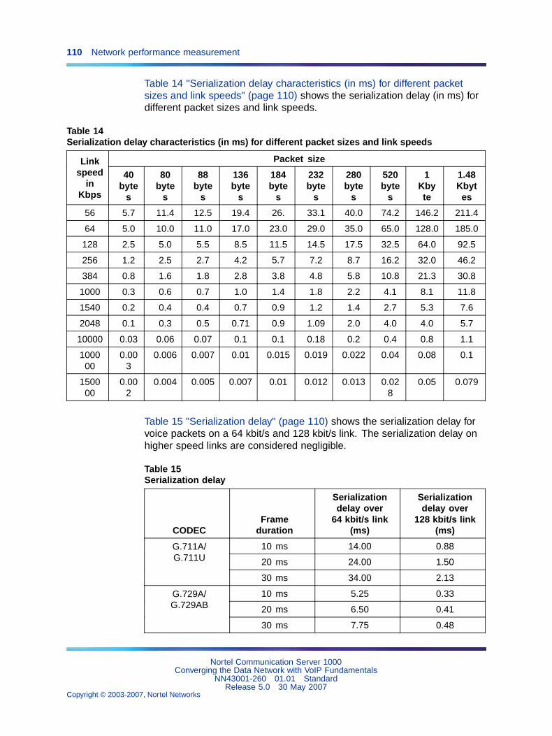
110 Network performance measurement
Table 14 "Serialization delay characteristics (in ms) for different packetsizes and link speeds" (page 110) shows the serialization delay (in ms) fordifferent packet sizes and link speeds.
Table 14Serialization delay characteristics (in ms) for different packet sizes and link speeds
Packet sizeLinkspeed
inKbps
40byte
s
80byte
s
88byte
s
136byte
s
184byte
s
232byte
s
280byte
s
520byte
s
1Kbyte
1.48Kbytes
56 5.7 11.4 12.5 19.4 26. 33.1 40.0 74.2 146.2 211.4
64 5.0 10.0 11.0 17.0 23.0 29.0 35.0 65.0 128.0 185.0
128 2.5 5.0 5.5 8.5 11.5 14.5 17.5 32.5 64.0 92.5
256 1.2 2.5 2.7 4.2 5.7 7.2 8.7 16.2 32.0 46.2
384 0.8 1.6 1.8 2.8 3.8 4.8 5.8 10.8 21.3 30.8
1000 0.3 0.6 0.7 1.0 1.4 1.8 2.2 4.1 8.1 11.8
1540 0.2 0.4 0.4 0.7 0.9 1.2 1.4 2.7 5.3 7.6
2048 0.1 0.3 0.5 0.71 0.9 1.09 2.0 4.0 4.0 5.7
10000 0.03 0.06 0.07 0.1 0.1 0.18 0.2 0.4 0.8 1.1
100000
0.003
0.006 0.007 0.01 0.015 0.019 0.022 0.04 0.08 0.1
150000
0.002
0.004 0.005 0.007 0.01 0.012 0.013 0.028
0.05 0.079
Table 15 "Serialization delay" (page 110) shows the serialization delay forvoice packets on a 64 kbit/s and 128 kbit/s link. The serialization delay onhigher speed links are considered negligible.
Table 15Serialization delay
CODECFrame
duration
Serializationdelay over
64 kbit/s link(ms)
Serializationdelay over
128 kbit/s link(ms)
10 ms 14.00 0.88
20 ms 24.00 1.50
G.711A/G.711U
30 ms 34.00 2.13
10 ms 5.25 0.33
20 ms 6.50 0.41
G.729A/G.729AB
30 ms 7.75 0.48
Nortel Communication Server 1000Converging the Data Network with VoIP Fundamentals
NN43001-260 01.01 StandardRelease 5.0 30 May 2007
Copyright © 2003-2007, Nortel Networks
.
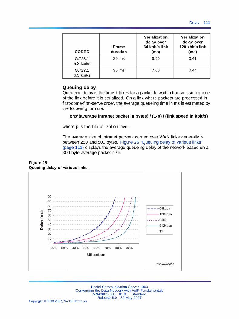
Delay 111
CODECFrame
duration
Serializationdelay over
64 kbit/s link(ms)
Serializationdelay over
128 kbit/s link(ms)
G.723.15.3 kbit/s
30 ms 6.50 0.41
G.723.16.3 kbit/s
30 ms 7.00 0.44
Queuing delayQueueing delay is the time it takes for a packet to wait in transmission queueof the link before it is serialized. On a link where packets are processed infirst-come-first-serve order, the average queueing time in ms is estimated bythe following formula:
p*p*(average intranet packet in bytes) / (1-p) / (link speed in kbit/s)
where p is the link utilization level.
The average size of intranet packets carried over WAN links generally isbetween 250 and 500 bytes. Figure 25 "Queuing delay of various links"(page 111) displays the average queueing delay of the network based on a300-byte average packet size.
Figure 25Queuing delay of various links
Nortel Communication Server 1000Converging the Data Network with VoIP Fundamentals
NN43001-260 01.01 StandardRelease 5.0 30 May 2007
Copyright © 2003-2007, Nortel Networks
.
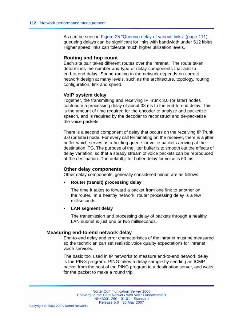
112 Network performance measurement
As can be seen in Figure 25 "Queuing delay of various links" (page 111),queueing delays can be significant for links with bandwidth under 512 kbit/s.Higher speed links can tolerate much higher utilization levels.
Routing and hop countEach site pair takes different routes over the intranet. The route takendetermines the number and type of delay components that add toend-to-end delay. Sound routing in the network depends on correctnetwork design at many levels, such as the architecture, topology, routingconfiguration, link and speed.
VoIP system delayTogether, the transmitting and receiving IP Trunk 3.0 (or later) nodescontribute a processing delay of about 33 ms to the end-to-end delay. Thisis the amount of time required for the encoder to analyze and packetizespeech, and is required by the decoder to reconstruct and de-packetizethe voice packets.
There is a second component of delay that occurs on the receiving IP Trunk3.0 (or later) node. For every call terminating on the receiver, there is a jitterbuffer which serves as a holding queue for voice packets arriving at thedestination ITG. The purpose of the jitter buffer is to smooth out the effects ofdelay variation, so that a steady stream of voice packets can be reproducedat the destination. The default jitter buffer delay for voice is 60 ms.
Other delay componentsOther delay components, generally considered minor, are as follows:
• Router (transit) processing delay
The time it takes to forward a packet from one link to another onthe router. In a healthy network, router processing delay is a fewmilliseconds.
• LAN segment delay
The transmission and processing delay of packets through a healthyLAN subnet is just one or two milliseconds.
Measuring end-to-end network delayEnd-to-end delay and error characteristics of the intranet must be measuredso the technician can set realistic voice quality expectations for intranetvoice services.
The basic tool used in IP networks to measure end-to-end network delayis the PING program. PING takes a delay sample by sending an ICMPpacket from the host of the PING program to a destination server, and waitsfor the packet to make a round trip.
Nortel Communication Server 1000Converging the Data Network with VoIP Fundamentals
NN43001-260 01.01 StandardRelease 5.0 30 May 2007
Copyright © 2003-2007, Nortel Networks
.
Delay 113
Some implementations of PING support the -v option for setting theTOS. CS 1000 allows the 8-bit DiffServ/TOS field to be set to any valuespecified by the IP network administrator for QoS management purposes.For example, a decimal value of 36 entered in TM is interpreted as TOSPrecedence = Priority and Reliability = High. If the -v option is not used,and if PING measurements are made on an intranet that uses prioritizationbased on the TOS field, the round trip time (rtt) measured will be higher thanthe actual delay of voice packets. See "Queueing" (page 94).
Note: Ensure that the DiffServ bytes are set to their intendedoperational values before taking measurements.
CS 1000 also has a utility called rPing (remote ping) so an IP Phone canping an IP address. The rPing command can be run from the SignalingServer OAM Command Line Interface (CLI). Refer to "Network DiagnosticUtilities" (page 191).
To ensure the delay sample results are representative of the IPLine_Node1(see "Sample PING output:" (page 113)):
Step Action
1 Attach the PING host to a "healthy" LAN segment.
2 Attach the LAN segment to the router intended to support the IPTelephony node.
3 Choose a destination host by following the same critical guidelinesas for the source host.
—End—
The size of the PING packets can be any number; the default is 60 bytes.
Sample PING output:IPLine_Node1% PING -s subnetA 60PING subnetA (10.3.2.7): 60 data bytes68 bytes from (10.3.2.7): icmp_seq=0 ttl=225 time=97ms68 bytes from (10.3.2.7): icmp_seq=0 ttl=225 time=100ms68 bytes from (10.3.2.7): icmp_seq=0 ttl=225 time=102ms68 bytes from (10.3.2.7): icmp_seq=0 ttl=225 time=97ms68 bytes from (10.3.2.7): icmp_seq=0 ttl=225 time=95ms68 bytes from (10.3.2.7): icmp_seq=0 ttl=225 time=94ms68 bytes from (10.3.2.7): icmp_seq=0 ttl=225 time=112ms68 bytes from (10.3.2.7): icmp_seq=0 ttl=225 time=97ms^? --- IPLine_Node1 PING Statistics ---8 packets transmitted, 8 packets received, 0% packet lossround-trip (ms) min/avg/max = 94/96/112
Nortel Communication Server 1000Converging the Data Network with VoIP Fundamentals
NN43001-260 01.01 StandardRelease 5.0 30 May 2007
Copyright © 2003-2007, Nortel Networks
.
114 Network performance measurement
Note: PING results can vary.
Assessment of sample PING output
Note: The round-trip time (rtt) is indicated by the time field.
The rtt from the PING output varies. It is from repeated sampling of rtt thata delay characteristic of the intranet can be obtained. To obtain a delaydistribution, the PING tool can be embedded in a script that controls thefrequency of the PING probes, timestamps and stores the samples in araw data file. The file can then be analyzed later using a spreadsheet oranother application. The technician can also check if the intranet’s networkmanagement software has any delay measurement modules that can obtaina delay distribution for a specific route.
Delay characteristics vary depending on the site pair and the time-of-day.The site pair is defined as the measurement between the host IP Line andthe remote subnet (for example, IP Line to subnet A in Figure 5 "Largecampus network example" (page 29)). The assessment of the intranet mustinclude taking delay measurements for each IP Line site pair. If there is asignificant variation of traffic on the intranet, include PING samples duringthe intranet’s peak hour. For a complete assessment of the intranet’s delaycharacteristics, obtain PING measurements over a period of at least oneweek.
Adjusting PING statisticsOne-way and round-tripPING statistics are based on round-trip measurements, while QoS metricsin the Transmission Rating model are one-way. Halve the delay and packeterror PING statistics to ensure the comparison is valid.
Adjustment due to IP Line processingPING statistics are measured from PING host to PING host. TransmissionRating QoS metrics are from end-user to end-user, and include componentsoutside the intranet. The PING statistic for delay needs to be furthermodified by adding 93ms to account for the processing and jitter bufferdelay of the nodes.
Note: There is no need to adjust error rates.
If the intranet measurement barely meets the round-trip QoS objectives, thetechnician must be aware of the possibility that one-way QoS is not beingmet in one of the directions of flow. This can apply even if the flow is on asymmetric route due to asymmetric behavior of data processing services.
Nortel Communication Server 1000Converging the Data Network with VoIP Fundamentals
NN43001-260 01.01 StandardRelease 5.0 30 May 2007
Copyright © 2003-2007, Nortel Networks
.
Delay 115
Other measurement considerationsThe PING statistics described above measure the intranet prior to CS1000 installation, which means that the measurement does not take intoconsideration the expected load created by CS 1000 users.
If the intranet capacity is tight and the VoIP traffic significant, considermaking intranet measurements under load. Load can be applied using trafficgenerator tools. The amount of load should match the IP Trunk-offeredtraffic estimated in the section "Estimate network loading caused by VoIPtraffic" (page 100).
Reducing delaysLink delay is the time it takes for a voice packet to be queued on thetransmission buffer of a link until it is received at the next hop router. Linkdelay can be reduced by:
• Upgrading link capacity — This reduces the serialization delay of thepacket, but also reduces link utilization and queueing delay. Beforeupgrading a link, the technician must check both routers connected tothe link to be upgraded and ensure compliance with router configurationguidelines.
• Implementing QoS mechanisms
To determine the links for upgrading, list all intranet links that support theIP Line traffic. This can be derived from the Traceroute output for eachsite pair. Use the intranet link utilization report and note the most usedlinks and the slowest links. Estimate the link delay of suspect links usingthe Traceroute results.
ExampleA 256 Kbps link from router1 to router2 has a high utilization. The followingTraceroute output traverses this link:IPLine_Node1% traceroute SubnetAtraceroute to SubnetA (10.3.2.7), 30 hops max,32 byte packets
router1 (10.8.0.1) 1 ms 1 ms 1 msrouter2 (10.18.0.2) 42 ms 44 ms 38 msrouter3 (10.28.0.3) 78 ms 70 ms 81 msrouter4 (10.3.0.1) 92 ms 90 ms 101 msSubnetA (10.3.2.7) 94 ms 97 ms 95 ms
The average rtt time on the example link is about 40 ms. The one-way linkdelay is about 20 ms, of which the circuit transmission and serializationdelay are just a few milliseconds. Most of this link’s delay is due to queueing.
Nortel Communication Server 1000Converging the Data Network with VoIP Fundamentals
NN43001-260 01.01 StandardRelease 5.0 30 May 2007
Copyright © 2003-2007, Nortel Networks
.
116 Network performance measurement
Reducing hop countConsider the current network topology and whether a more efficient designwhich reduces hop count can be implemented. Reducing hops reducesfixed and variable IP packet delay and improves VoIP QoS. It may alsosimplify end-to-end QoS engineering for packet delay, jitter, and packet loss.
Recording routesThe Traceroute tool records routing information for all source-destinationpairs as part of the network assessment. An example of Traceroute outputis shown below:ipline_node1% traceroute subnetAtraceroute to subnetA 10.3.2.7, 30 hops max, 32 byte packets1 r6 (10.8.0.1) 1 ms 1 ms 1 ms2 r5 (10.18.0.2) 42 ms 44 ms 38 ms3 r4 (10.28.0.3) 78 ms 70 ms 81 ms4 r1 (10.3.0.1) 92 ms 90 ms 101 ms5 subnetA (10.3.2.7) 94 ms 97 ms 95 ms
Traceroute is also used to verify whether routing in the intranet is symmetricfor each source-destination pair. This is done using the -g loose sourcerouting option, for example:
ipline_node1% traceroute -g subnetA ipline_node1
For information on the rTraceRoute command, refer to "Network DiagnosticUtilities" (page 191).
Routing issuesUnnecessary delay can be introduced by routing irregularities. A routingimplementation might overlook a substantially better route. A high-delayvariation can be caused by routing instability, incorrectly configured routing,inappropriate load splitting, or frequent changes to the intranet. Severeasymmetrical routing results in one site perceiving a poorer QoS thananother.
The Traceroute program can be used to uncover these routing anomalies.Then routing implementation and policies can be audited and corrected.
JitterJitter (also known as variable delay) is the variation in the amount of timeit takes for consecutive packets to travel from sender to receiver. Thereis a fixed baseline delay (the absolute fastest time for a voice packet topass through the network), and a variation in packet flow. The variationin the delay is jitter.
The primary cause of jitter (variable delay) is contention (competition fornetwork access), also known as queueing delay. Variable delays areaffected by the amount of network traffic.
Nortel Communication Server 1000Converging the Data Network with VoIP Fundamentals
NN43001-260 01.01 StandardRelease 5.0 30 May 2007
Copyright © 2003-2007, Nortel Networks
.
Jitter 117
Jitter has a pronounced effect on real-time, delay-sensitive applications,such as video and voice. These applications need to receive packets ata constant rate, with a fixed delay between consecutive packets. If thearrival rate varies, jitter occurs, and application performance degrades.Minimal jitter might be acceptable, but if jitter increases, the applicationcould become unusable.
Some settings on devices such as VoIP gateways and IP Phones cancompensate for a finite (specified) amount of jitter.
If an adaptive jitter buffer is used, delay is kept to a minimum during periodsof low jitter. The adaptive buffer can adjust to higher levels of jitter, withina limited range, during periods of higher traffic volume. If the networkbecomes congested, jitter and packet loss can become undefined, andreal-time interactive applications can become unusable.
Voice applications require the voice packets to be fed to the decoder at aconstant rate. If the next voice packet does not arrive in time to take its turnto be decoded, the packet is considered lost. Packet Loss Concealment(PLC) attempts to smooth over the lost voice packet. PLC replays theprevious voice packet until the next voice packet arrives. A PLC algorithmcan repair losses of 40-60 ms. Longer gaps in the signal must be muted.If jitter is high, whole groups of packets can be late or lost, and output cancontain muted segments.
All networks have some jitter. This is due to differences in delay at eachnetwork node, as packets are queued. If jitter is contained within specifiedlimits, QoS can be maintained.
In VoIP, jitter is the total amount of variable delay encountered during theend-to-end processing of voice packets.
Jitter buffers are used on the receive-side of a call to smooth out smallvariations in the packet time-of arrival. This allows data to be unpacked andsent to the decoder as a constant stream. Since all buffering increasesend-to-end delay, jitter buffer length (duration) must be kept to a minimum.If a network has been engineered to have minimal jitter, the jitter buffercan be very small.
The following factors contribute to the total variation in delay:
• packet contention during node queueing
• network conditions such as routing and transmission queueing
• router and switch (statistical multiplexer) performance under load
• link speed
• voice and data packet size
• exit (egress) queue buffer size
Queueing delay occurs at the exit port of every device on the network.
Nortel Communication Server 1000Converging the Data Network with VoIP Fundamentals
NN43001-260 01.01 StandardRelease 5.0 30 May 2007
Copyright © 2003-2007, Nortel Networks
.
118 Network performance measurement
Call Admission Control (CAC) performs packet admission and blockingfunctions. Voice packets are admitted to the network when the network canadequately support them. The packets are denied admission when thenetwork cannot support them as defined in the Service Level Agreement.
When voice and data packets share a low-speed WAN connection (< 1Mbps), the larger data packets introduce queuing delay to the smaller voicepackets waiting to be queued onto the WAN connection. Therefore, thesmaller voice packets do not arrive at the same fixed time interval as theyare transmitted from their source. The arrival time of the voice packetsvaries because interjected data packets of varying sizes introduce a varyingamount of jitter (queuing delay).
Jitter buffersWhen voice and data packets share a high-speed connection (> 1 Mbps),the jitter introduced by the WAN connection becomes insignificant.The jitterin high-speed networks is affected by the buffer size of a router and theload/congestion in the router. Jitter buffers are designed to smooth outirregular packet arrival. This is done by collecting incoming packets andholding them in a buffer long enough to allow the slowest packets to arrive.The packets are then played in the correct sequence. Jitter buffers solve thelate and lost packet problem, but add to total end-to-end delay.
Late packetsPackets that arrive outside the window allowed by the jitter buffer arediscarded by IP Line. To determine which PING samples to ignore, calculatethe average one-way delay based on all the samples.
To calculate late packets, double the value of the nominal jitter buffer setting.For example, assume:
• the average one-way delay is 50 ms
• the jitter buffer is set to a nominal (or average) value of 40 ms
• then the maximum value is 2 x 40 + 50 = 130 ms
Therefore, any packet with a one-way delay of greater than 130 ms is late,and must be added to the total number of packets lost.
Adjusting jitter buffer sizeThe jitter buffer parameters directly affect end-to-end delay. Lowering thevoice playout settings decreases one-way delay, but there is less waitingtime for voice packets that arrive late.
Nortel Communication Server 1000Converging the Data Network with VoIP Fundamentals
NN43001-260 01.01 StandardRelease 5.0 30 May 2007
Copyright © 2003-2007, Nortel Networks
.
Jitter 119
The jitter buffer setting is configured on the voice gateway channels of theVoice Gateway Media Card, and are sent out to IP Phones. The jitter buffersize is set when configuring the DSP Profiles:
• in the IP Telephony application
• in the selected CODEC in Element Manager
The jitter buffer is statically configured and is the same for all devices in thenetwork. The jitter buffer size range is 0-200 ms. The default jitter buffervalue is 50 ms. However, the jitter buffer setting that is used on the VoiceGateway Media Card is a multiple of the CODEC frame size. The settingis automatically adjusted to be greater than or equal to the jitter buffervalue set in the DSP Profile tab. As each call is set up, the jitter buffer foreach device is set to the nearest whole number increment of the selectedCODEC frame size.
For example, if the jitter buffer is configured as the default 50 ms in the DSPProfiles, but a 20 ms CODEC is used, the jitter buffer is set to 60 ms, whichis the nearest whole number increment.
50 ms / 20 ms = 2.52.5 rounded up to the nearest whole number increment is 33 x 20 ms = 60 ms
If the jitter buffer is configured as zero, the depth of the jitter buffer is setto the smallest value the device can support. In practice, the optimumdepth of the jitter queue is different for each call. For telephones on a localLAN connection, a short jitter queue is desirable to minimize delay. Fortelephones several router hops away, a longer jitter queue is required.
Lowering the jitter buffer size decreases the one-way delay of voice packets.If the setting for the jitter buffer size is too small, packets are discardedunnecessarily. Discarded packets result in poorer speech quality and canbe heard as clicks or choppy speech.
If the technician decides to discard packets to downsize the jitter buffer,the technician must do the following:
• Check the delay variation statistics.
Obtain the one-way delay distributions originating from all source IPLine sites.
• Compute the standard deviation of one-way delay for every flow.
Some traffic sources with few hop counts yield small delay variations,but it is the flows that produce great delay variations that should be usedto determine whether it is acceptable to resize the jitter buffer.
• Compute the standard deviation (s) of one-way delay for that flow.
Do not set the set the jitter buffer size smaller than 2 sec.
Nortel Communication Server 1000Converging the Data Network with VoIP Fundamentals
NN43001-260 01.01 StandardRelease 5.0 30 May 2007
Copyright © 2003-2007, Nortel Networks
.
120 Network performance measurement
The IP Phone firmware must also be configured for jitter buffers. However,instead of specifying the jitter buffer size in ms, it is configured with thenumber of frames to be held in the jitter buffer, such as 1, 2, or 3.
Recommendation
To achieve maximum voice quality, Nortel strongly recommends that IP Phonefirmware be configured with a jitter buffer size of 3; however, a well-engineerednetwork can function with a jitter buffer size of 2, which increases perceivedvoice quality.
Jitter measurement toolsOnce a CS 1000 system has been installed, the average jitter experiencedby IP Phones or media cards may be monitored on a per-call basis byusing the RTPTraceShow command from the signaling server CLI. The CS1000 system can also be configured to transmit SNMP alarms if a certainaverage jitter level is exceeded. For more information, refer to "ProactiveVoice Quality Management" (page 199).
Packet lossPacket loss is the number of packets lost during transmission. It is usuallymeasured as a percentage of the total packets exchanged.
Physical medium lossLoss can occur due to errors created by the physical medium used totransmit the data.
Most landline connections have very low loss, measured in Bit Error Rate(BER). Wireless connections, such as satellite, mobile, or fixed wirelessnetworks, have a high BER. The BER can vary due to the following:
• radio frequency interference
• cell hand-off during roaming calls
• weather conditions, such as fog and rain
• physical obstacles, such as trees, buildings, and mountains
Wireless technology usually transmits redundant information, since packetsare often dropped during transmission due to the physical medium.
Congestion lossCongestion loss consists of true loss (buffer overflow at router queues)and late packets. Loss also occurs when congested network nodes droppackets. The majority of packet loss is caused by congestion.
Nortel Communication Server 1000Converging the Data Network with VoIP Fundamentals
NN43001-260 01.01 StandardRelease 5.0 30 May 2007
Copyright © 2003-2007, Nortel Networks
.
Packet loss 121
VoIP uses User Datagram Protocol (UDP). UDP is a connectionless protocolwhich, unlike TCP, cannot retransmit lost packets. A packet is sent fromthe source to the destination with no means to determine if that packetwas received or not.
If a network becomes congested to the point that packets are lost, voicequality is degraded. Traffic is discarded if the transmit queue of an uplinkhas less bandwidth available than the total amount of bandwidth trying touse that link. This situation is also known as a "bottleneck".
Congestion can lead to packet loss. Mechanisms to avoid networkcongestion can be used. One such mechanism is called Random EarlyDiscard (RED). RED deliberately drops packets once the network trafficreaches a specified threshold. The dropped packets cause TCP to reduceits window size and send fewer packets, thus reducing network traffic.
Note: RED provides congestion control only for applications orprotocols that have the TCP-like ability to reduce network traffic.
UDP packets dropped in a network cannot be re-transmitted. Flow rates arenot adjusted by devices that communicate through UDP.
Without discard priorities, it would be necessary to separate packets intodifferent queues in a network node to provide different levels of service. Thisis expensive to implement, as only a limited number of hardware queues(usually eight or fewer) are available on networking devices. Though somedevices have software-based queues, their increased use reduces networknode performance.
With discard priorities, although packets are placed in the same queue, theyare divided into virtual sub-queues, determined by their assigned discardpriority. For example, if a product supports three discard priorities, then theproduct’s queue provides three sub-queues, and therefore, three QoS levels.
Packets are usually lost due to a router dropping packets when links arecongested.
Individual packets that are delayed much more than the baseline delay(variable delay) are referred to as jitter. Excess jitter causes packet losswhich can result in choppy or unintelligible speech.
Packet loss occurs in the following situations:
• during network congestion
• misconfigured LAN settings
• misconfigured clock settings
Nortel Communication Server 1000Converging the Data Network with VoIP Fundamentals
NN43001-260 01.01 StandardRelease 5.0 30 May 2007
Copyright © 2003-2007, Nortel Networks
.
122 Network performance measurement
• bit errors in the network
Recommendation
To achieve maximum voice quality, Nortel strongly recommends that packetloss = 0%.
Packet Loss Concealment (PLC) is used to minimize the noticeable effectsof packet loss.
Measuring end-to-end packet lossAfter a CS 1000 installation, use RTPTraceShow and PVQM SNMP alarms.
The PING program also reports whether the ICMP packet successfullycompleted its round trip. Use the same PING host setup to measureend-to-end error, and in making delay measurement, use the same packetsize parameter.
Multiple PING samples must be used when sampling for error rate. Packetloss rate (PLR) is the error rate statistic collected by multiple PING samples.To be statistically significant, at least 300 samples must be used. Obtainingan error distribution requires running PING over a greater period of time.
For more information, refer to "Network Diagnostic Utilities" (page 191).
Packet Loss ConcealmentThe term CODEC stands for coder/decoder. A CODEC executes acompression algorithm (a specialized computer program) that reduces thenumber of bytes required to encode digital data. This reduces packet sizeand bandwidth requirements. As well, smaller packets are less likely tobe lost.
CODECs designed for packet networks, such as G.729, have built-in PacketLoss Concealment (PLC). PLC minimizes the impact of lost packets onan audio signal, by mixing in synthesized speech derived from previouspackets.
When a speech CODEC operates in normal mode, a receiver decodespackets and sends the output to an audio port. A PLC algorithm saves acopy of the recent audio output, which is used to create a signal to replacethe missing speech if lost data is encountered. How this information is useddepends on the PLC algorithm. Some simple algorithms smooth over gapsin the signal to remove clicks. Other algorithms replay an earlier packet tofill in the gap. More sophisticated algorithms tweak the replacement signalto make it sound more natural. The best algorithms can repair a 20-40 ms
Nortel Communication Server 1000Converging the Data Network with VoIP Fundamentals
NN43001-260 01.01 StandardRelease 5.0 30 May 2007
Copyright © 2003-2007, Nortel Networks
.
Network delay and packet loss evaluation example 123
gap with little audible distortion. The PLC operates constantly, generatingspeech to replace the next packet in the event it is lost. The use of a PLCadds a small fixed delay to the call’s baseline delay.
PLC is necessary to achieve acceptable IP speech quality.
Reducing packet lossPacket loss in intranets is generally related to congestion in the network.Bottlenecks in links are where the packet loss is high because packets getdropped, as the packets arrive faster than the link can transmit them. Thetask of upgrading highly utilized links can remove the source of packet losson a particular flow. An effort to reduce hop count gives fewer opportunitiesfor routers and links to drop packets.
Other causes of packet loss not related to queueing delay are as follows:
• Poor link quality — The underlying circuit could have transmissionproblems, high line error rates, and be subject to frequent outages. Thecircuit might possibly be provisioned on top of other services, suchas X.25, Frame Relay, or ATM. Check with the service provider forinformation.
• Overloaded CPU — This is a commonly-monitored statistic collectedby network management systems. If a router is overloaded, it meansthat the router is constantly performing processing-intensive tasks,which impede the router from forwarding packets. Determine the CPUutilization threshold and check if any suspect router conforms to it. Therouter may need to be re-configured or upgraded.
• Saturation — Routers can be overworked when configured with toomany high capacity links and too many high traffic links. Ensure thatrouters are dimensioned according to vendor guidelines.
• LAN saturation — Packets may be dropped on under-engineered orfaulty LAN segments.
• Jitter buffer too small — Packets that arrive at the destination, but toolate to be placed in the jitter buffer, should be considered lost packets.
• Frame slips — Ensure that clocks are synchronized correctly.
Network delay and packet loss evaluation exampleFrom PING data, calculate the average one-way delay (halved from PINGoutput and adding 93 ms IP Trunk 3.0 (or later) processing delay) andstandard deviation for latency. Do a similar calculation for packet losswithout adjustment.
Adding a standard deviation to the mean of both delay and loss is forplanning purposes. A customer might want to know whether trafficfluctuation in their intranet reduces the user’s QoS.
Nortel Communication Server 1000Converging the Data Network with VoIP Fundamentals
NN43001-260 01.01 StandardRelease 5.0 30 May 2007
Copyright © 2003-2007, Nortel Networks
.
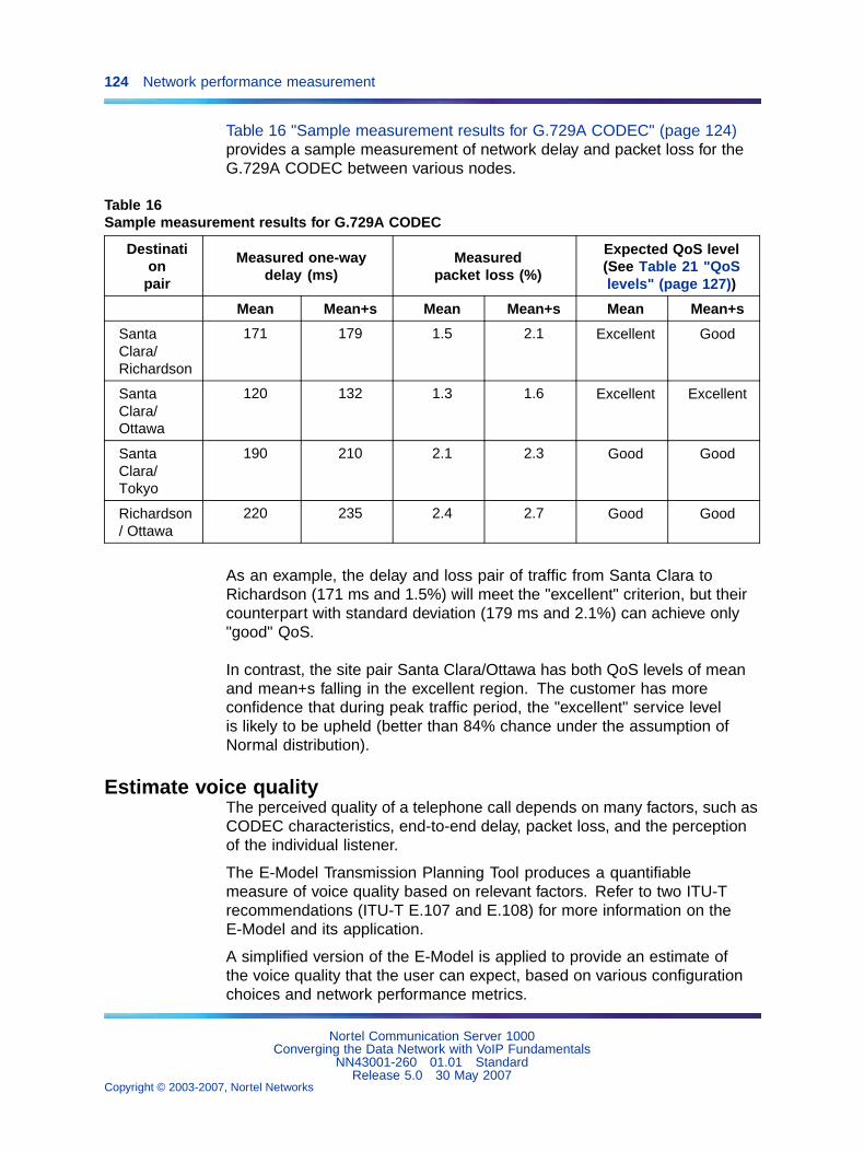
124 Network performance measurement
Table 16 "Sample measurement results for G.729A CODEC" (page 124)provides a sample measurement of network delay and packet loss for theG.729A CODEC between various nodes.
Table 16Sample measurement results for G.729A CODEC
Destination
pair
Measured one-waydelay (ms)
Measuredpacket loss (%)
Expected QoS level(See Table 21 "QoSlevels" (page 127))
Mean Mean+s Mean Mean+s Mean Mean+s
SantaClara/Richardson
171 179 1.5 2.1 Excellent Good
SantaClara/Ottawa
120 132 1.3 1.6 Excellent Excellent
SantaClara/Tokyo
190 210 2.1 2.3 Good Good
Richardson/ Ottawa
220 235 2.4 2.7 Good Good
As an example, the delay and loss pair of traffic from Santa Clara toRichardson (171 ms and 1.5%) will meet the "excellent" criterion, but theircounterpart with standard deviation (179 ms and 2.1%) can achieve only"good" QoS.
In contrast, the site pair Santa Clara/Ottawa has both QoS levels of meanand mean+s falling in the excellent region. The customer has moreconfidence that during peak traffic period, the "excellent" service levelis likely to be upheld (better than 84% chance under the assumption ofNormal distribution).
Estimate voice qualityThe perceived quality of a telephone call depends on many factors, such asCODEC characteristics, end-to-end delay, packet loss, and the perceptionof the individual listener.
The E-Model Transmission Planning Tool produces a quantifiablemeasure of voice quality based on relevant factors. Refer to two ITU-Trecommendations (ITU-T E.107 and E.108) for more information on theE-Model and its application.
A simplified version of the E-Model is applied to provide an estimate ofthe voice quality that the user can expect, based on various configurationchoices and network performance metrics.
Nortel Communication Server 1000Converging the Data Network with VoIP Fundamentals
NN43001-260 01.01 StandardRelease 5.0 30 May 2007
Copyright © 2003-2007, Nortel Networks
.
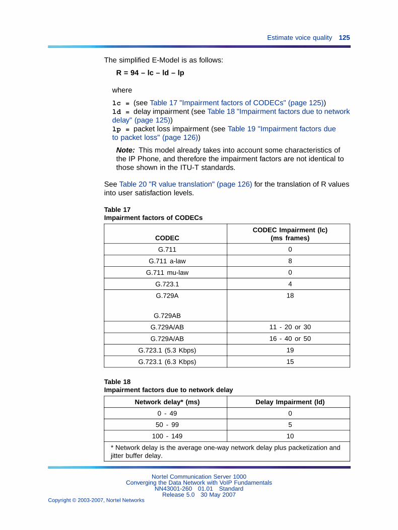
Estimate voice quality 125
The simplified E-Model is as follows:
R = 94 – lc – ld – lp
where
lc = (see Table 17 "Impairment factors of CODECs" (page 125))ld = delay impairment (see Table 18 "Impairment factors due to networkdelay" (page 125))lp = packet loss impairment (see Table 19 "Impairment factors dueto packet loss" (page 126))
Note: This model already takes into account some characteristics ofthe IP Phone, and therefore the impairment factors are not identical tothose shown in the ITU-T standards.
See Table 20 "R value translation" (page 126) for the translation of R valuesinto user satisfaction levels.
Table 17Impairment factors of CODECs
CODECCODEC Impairment (lc)
(ms frames)
G.711 0
G.711 a-law 8
G.711 mu-law 0
G.723.1 4
G.729A
G.729AB
18
G.729A/AB 11 - 20 or 30
G.729A/AB 16 - 40 or 50
G.723.1 (5.3 Kbps) 19
G.723.1 (6.3 Kbps) 15
Table 18Impairment factors due to network delay
Network delay* (ms) Delay Impairment (ld)
0 - 49 0
50 - 99 5
100 - 149 10
* Network delay is the average one-way network delay plus packetization andjitter buffer delay.
Nortel Communication Server 1000Converging the Data Network with VoIP Fundamentals
NN43001-260 01.01 StandardRelease 5.0 30 May 2007
Copyright © 2003-2007, Nortel Networks
.
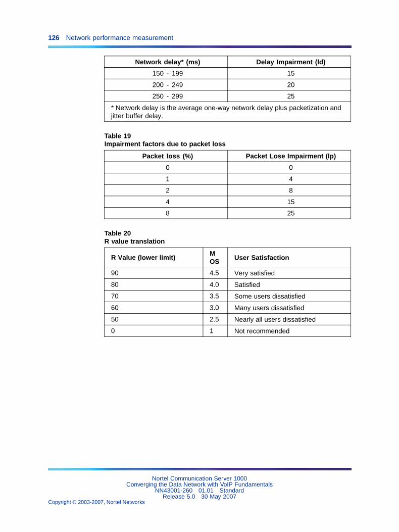
126 Network performance measurement
Network delay* (ms) Delay Impairment (ld)
150 - 199 15
200 - 249 20
250 - 299 25
* Network delay is the average one-way network delay plus packetization andjitter buffer delay.
Table 19Impairment factors due to packet loss
Packet loss (%) Packet Lose Impairment (lp)
0 0
1 4
2 8
4 15
8 25
Table 20R value translation
R Value (lower limit)MOS User Satisfaction
90 4.5 Very satisfied
80 4.0 Satisfied
70 3.5 Some users dissatisfied
60 3.0 Many users dissatisfied
50 2.5 Nearly all users dissatisfied
0 1 Not recommended
Nortel Communication Server 1000Converging the Data Network with VoIP Fundamentals
NN43001-260 01.01 StandardRelease 5.0 30 May 2007
Copyright © 2003-2007, Nortel Networks
.
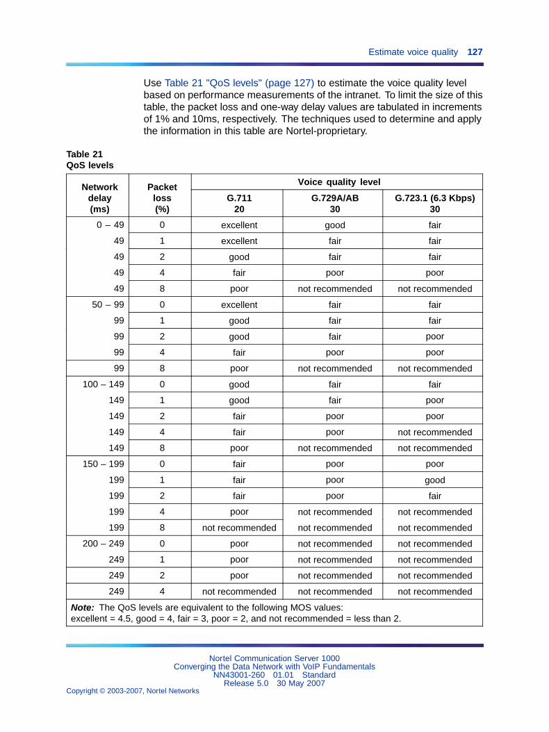
Estimate voice quality 127
Use Table 21 "QoS levels" (page 127) to estimate the voice quality levelbased on performance measurements of the intranet. To limit the size of thistable, the packet loss and one-way delay values are tabulated in incrementsof 1% and 10ms, respectively. The techniques used to determine and applythe information in this table are Nortel-proprietary.
Table 21QoS levels
Voice quality levelNetworkdelay(ms)
Packetloss(%)
G.71120
G.729A/AB30
G.723.1 (6.3 Kbps)30
0 – 49 0 excellent good fair
49 1 excellent fair fair
49 2 good fair fair
49 4 fair poor poor
49 8 poor not recommended not recommended
50 – 99 0 excellent fair fair
99 1 good fair fair
99 2 good fair poor
99 4 fair poor poor
99 8 poor not recommended not recommended
100 – 149 0 good fair fair
149 1 good fair poor
149 2 fair poor poor
149 4 fair poor not recommended
149 8 poor not recommended not recommended
150 – 199 0 fair poor poor
199 1 fair poor good
199 2 fair poor fair
199 4 poor not recommended not recommended
199 8 not recommended not recommended not recommended
200 – 249 0 poor not recommended not recommended
249 1 poor not recommended not recommended
249 2 poor not recommended not recommended
249 4 not recommended not recommended not recommended
Note: The QoS levels are equivalent to the following MOS values:excellent = 4.5, good = 4, fair = 3, poor = 2, and not recommended = less than 2.
Nortel Communication Server 1000Converging the Data Network with VoIP Fundamentals
NN43001-260 01.01 StandardRelease 5.0 30 May 2007
Copyright © 2003-2007, Nortel Networks
.
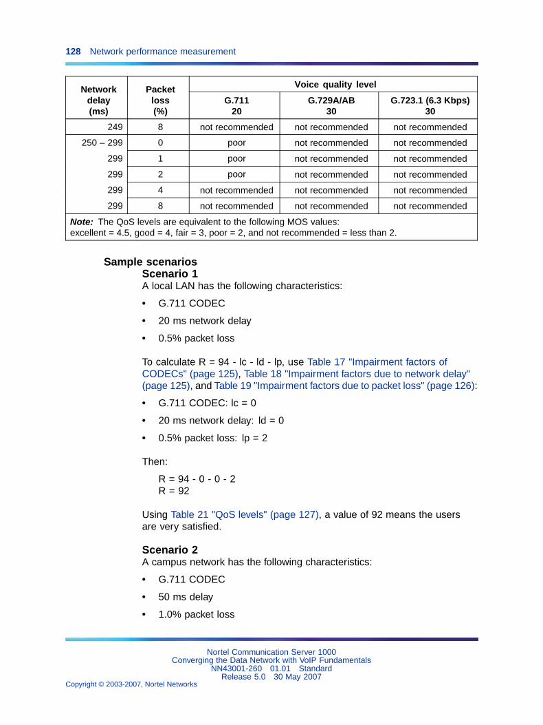
128 Network performance measurement
Voice quality levelNetworkdelay(ms)
Packetloss(%)
G.71120
G.729A/AB30
G.723.1 (6.3 Kbps)30
249 8 not recommended not recommended not recommended
250 – 299 0 poor not recommended not recommended
299 1 poor not recommended not recommended
299 2 poor not recommended not recommended
299 4 not recommended not recommended not recommended
299 8 not recommended not recommended not recommended
Note: The QoS levels are equivalent to the following MOS values:excellent = 4.5, good = 4, fair = 3, poor = 2, and not recommended = less than 2.
Sample scenariosScenario 1A local LAN has the following characteristics:
• G.711 CODEC
• 20 ms network delay
• 0.5% packet loss
To calculate R = 94 - lc - ld - lp, use Table 17 "Impairment factors ofCODECs" (page 125), Table 18 "Impairment factors due to network delay"(page 125), and Table 19 "Impairment factors due to packet loss" (page 126):
• G.711 CODEC: lc = 0
• 20 ms network delay: ld = 0
• 0.5% packet loss: lp = 2
Then:
R = 94 - 0 - 0 - 2R = 92
Using Table 21 "QoS levels" (page 127), a value of 92 means the usersare very satisfied.
Scenario 2A campus network has the following characteristics:
• G.711 CODEC
• 50 ms delay
• 1.0% packet loss
Nortel Communication Server 1000Converging the Data Network with VoIP Fundamentals
NN43001-260 01.01 StandardRelease 5.0 30 May 2007
Copyright © 2003-2007, Nortel Networks
.
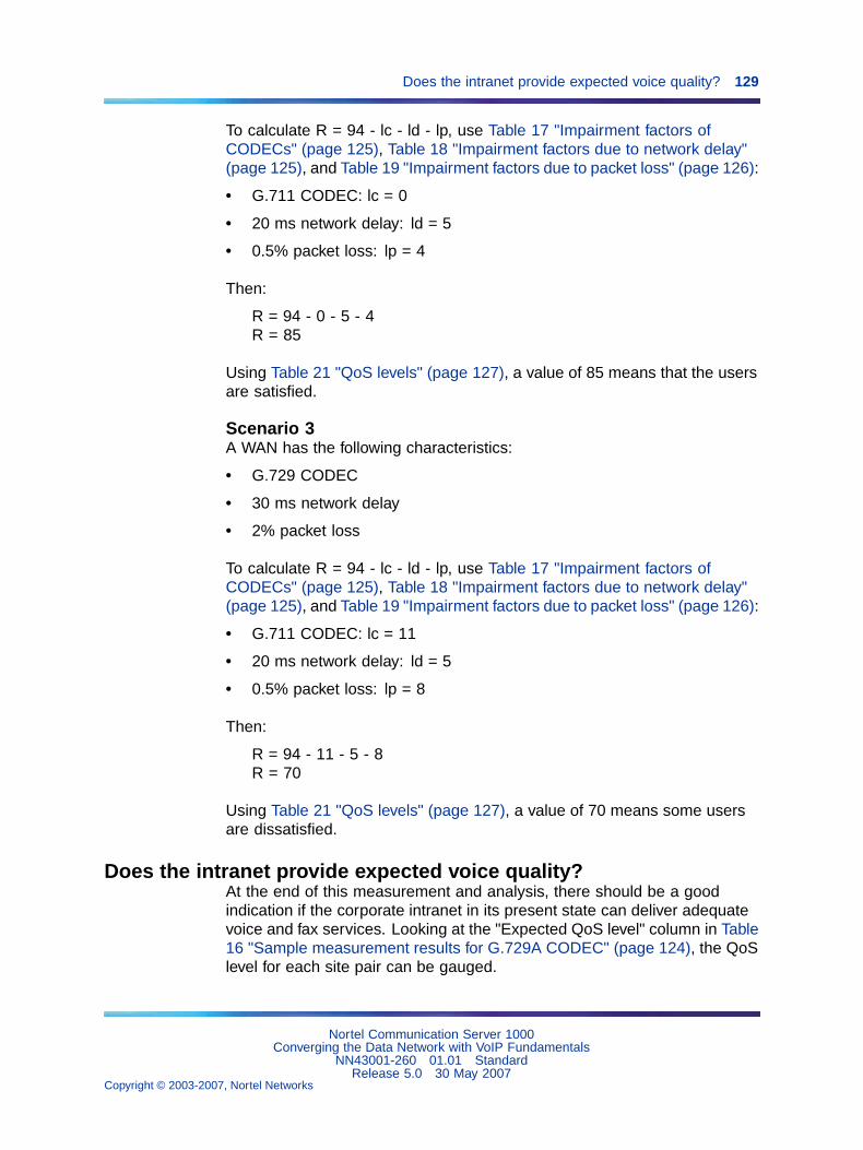
Does the intranet provide expected voice quality? 129
To calculate R = 94 - lc - ld - lp, use Table 17 "Impairment factors ofCODECs" (page 125), Table 18 "Impairment factors due to network delay"(page 125), and Table 19 "Impairment factors due to packet loss" (page 126):
• G.711 CODEC: lc = 0
• 20 ms network delay: ld = 5
• 0.5% packet loss: lp = 4
Then:
R = 94 - 0 - 5 - 4R = 85
Using Table 21 "QoS levels" (page 127), a value of 85 means that the usersare satisfied.
Scenario 3A WAN has the following characteristics:
• G.729 CODEC
• 30 ms network delay
• 2% packet loss
To calculate R = 94 - lc - ld - lp, use Table 17 "Impairment factors ofCODECs" (page 125), Table 18 "Impairment factors due to network delay"(page 125), and Table 19 "Impairment factors due to packet loss" (page 126):
• G.711 CODEC: lc = 11
• 20 ms network delay: ld = 5
• 0.5% packet loss: lp = 8
Then:
R = 94 - 11 - 5 - 8R = 70
Using Table 21 "QoS levels" (page 127), a value of 70 means some usersare dissatisfied.
Does the intranet provide expected voice quality?At the end of this measurement and analysis, there should be a goodindication if the corporate intranet in its present state can deliver adequatevoice and fax services. Looking at the "Expected QoS level" column in Table16 "Sample measurement results for G.729A CODEC" (page 124), the QoSlevel for each site pair can be gauged.
Nortel Communication Server 1000Converging the Data Network with VoIP Fundamentals
NN43001-260 01.01 StandardRelease 5.0 30 May 2007
Copyright © 2003-2007, Nortel Networks
.
130 Network performance measurement
In order to offer voice and fax services over the intranet, keep the networkwithin "Good" or "Excellent" QoS level at the Mean+s operating region. Faxservices should not be offered on routes that have only "Fair" or "Poor"QoS levels.
If the expected QoS levels on some or all routes fall short of "Good",evaluate the options and costs to upgrade the intranet. Estimate thereduction in one-way delay that must be achieved to raise the QoS level.Often this involves a link upgrade, a topology change, or an implementationof QoS in the network.
A decision can be made to keep costs down and accept a temporary "Fair"QoS level for a selected route. In that case, having made a calculatedtrade-off in quality, carefully monitor the QoS level, reset expectations withthe end users and be receptive to user feedback.
Recommendation
Nortel strongly recommends a minimum R-value of 70.
Nortel Communication Server 1000Converging the Data Network with VoIP Fundamentals
NN43001-260 01.01 StandardRelease 5.0 30 May 2007
Copyright © 2003-2007, Nortel Networks
.
131
Server LAN design
ContentsThis section contains information on the following topics:
"Introduction" (page 132)
"Server subnets" (page 133)
"CS 1000 Ethernet connections" (page 137)
"Ethernet requirements" (page 142)
"General Layer 2 considerations" (page 142)
"CS 1000 network interfaces" (page 143)
"Broadcast and Multicast rate limiting" (page 144)
"Network interface half- and full-duplex operation" (page 144)
"Spanning Tree options on Layer 2 switches" (page 145)
"How to avoid system interruption" (page 145)
"IP address requirements" (page 147)
"General requirements for node IP addressing" (page 147)
"ELAN and TLAN subnet configuration examples" (page 150)
"Selecting public or private IP addresses" (page 151)
"ELAN and TLAN network interfaces on a single subnet" (page 152)
"Multiple nodes on the same ELAN and TLAN subnets" (page 153)
"Guidelines for configuring a routable ELAN subnet" (page 153)
"Redundant LAN design" (page 154)
"Single physical location" (page 154)
"CS 1000E Campus redundancy" (page 158)
"Distributed IP Expansion Media Gateway requirements" (page 160)
"IP expansion link requirements" (page 161)
"Bandwidth planning" (page 162)
"Monitoring IP expansion link QoS" (page 162)
Nortel Communication Server 1000Converging the Data Network with VoIP Fundamentals
NN43001-260 01.01 StandardRelease 5.0 30 May 2007
Copyright © 2003-2007, Nortel Networks
.
132 Server LAN design
"IP expansion link Packet Delay Variation jitter buffer" (page 163)
"Distributed Media Gateway 1000E" (page 164)
"Campus-distributed Media Gateway enhancements" (page 164)
"Campus-distributed Media Gateway 1000E IP address configuration"(page 166)
"Sample system layout" (page 166)
"Address and connection tables" (page 167)
IntroductionThis chapter describes the requirements for creating and maintaining arobust, redundant server network.
The system servers and gateways can require up to four separatesub-networks. In order to differentiate the subnets and the correspondingnetwork interface on each device, they are named:
• ELAN subnet
• TLAN subnet
• Nortel Server subnet
The fourth subnet, although not requiring any Layer 2 or Layer 3 switches, isfor the IP expansion links network interfaces which connect SSC cards in aCS 1000S or Media Gateway 1000T (MG 1000T).
Figure 26 "Example: Enterprise IP Network (that is, describing the wholeof the data network structure)" (page 133) shows the logical elements ofbasic system connectivity in a CS 1000 network.
Nortel Communication Server 1000Converging the Data Network with VoIP Fundamentals
NN43001-260 01.01 StandardRelease 5.0 30 May 2007
Copyright © 2003-2007, Nortel Networks
.
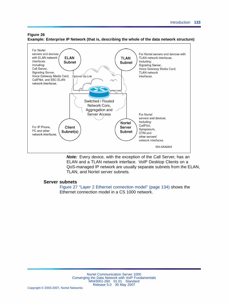
Introduction 133
Figure 26Example: Enterprise IP Network (that is, describing the whole of the data network structure)
Note: Every device, with the exception of the Call Server, has anELAN and a TLAN network interface. VoIP Desktop Clients on aQoS-managed IP network are usually separate subnets from the ELAN,TLAN, and Nortel server subnets.
Server subnetsFigure 27 "Layer 2 Ethernet connection model" (page 134) shows theEthernet connection model in a CS 1000 network.
Nortel Communication Server 1000Converging the Data Network with VoIP Fundamentals
NN43001-260 01.01 StandardRelease 5.0 30 May 2007
Copyright © 2003-2007, Nortel Networks
.
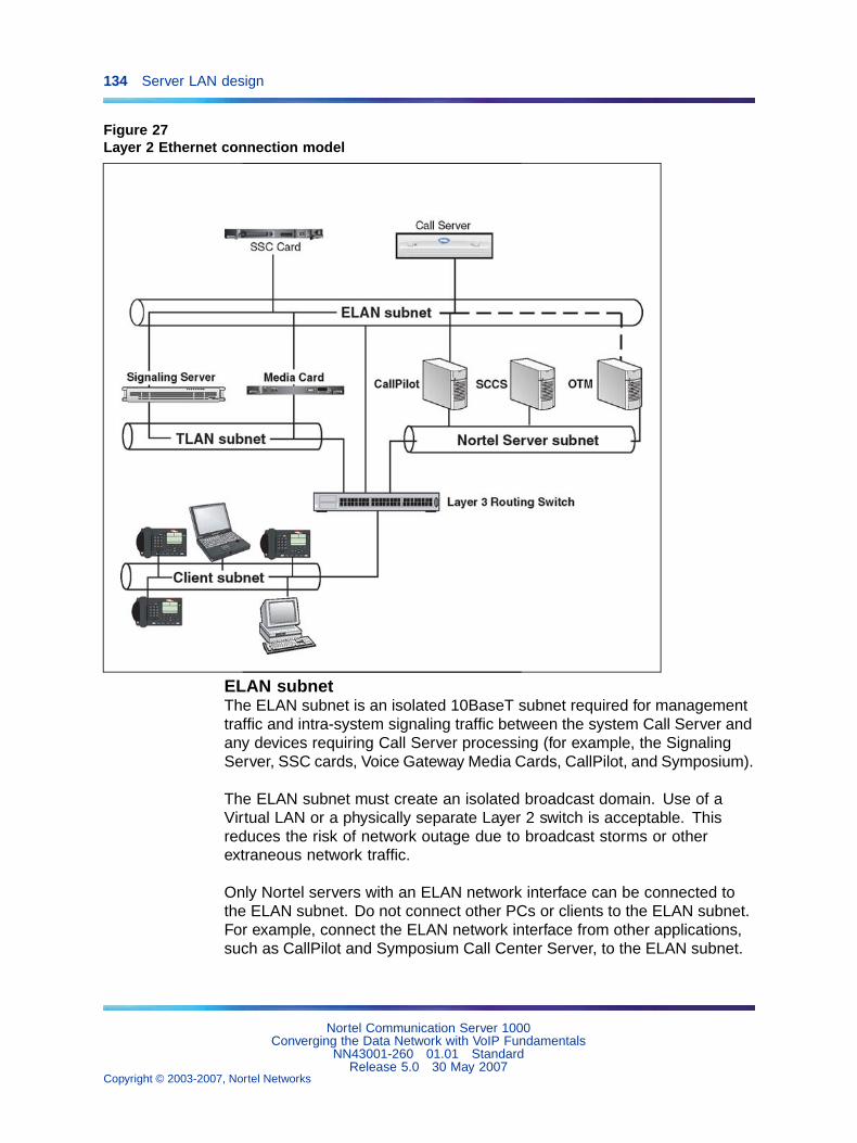
134 Server LAN design
Figure 27Layer 2 Ethernet connection model
ELAN subnetThe ELAN subnet is an isolated 10BaseT subnet required for managementtraffic and intra-system signaling traffic between the system Call Server andany devices requiring Call Server processing (for example, the SignalingServer, SSC cards, Voice Gateway Media Cards, CallPilot, and Symposium).
The ELAN subnet must create an isolated broadcast domain. Use of aVirtual LAN or a physically separate Layer 2 switch is acceptable. Thisreduces the risk of network outage due to broadcast storms or otherextraneous network traffic.
Only Nortel servers with an ELAN network interface can be connected tothe ELAN subnet. Do not connect other PCs or clients to the ELAN subnet.For example, connect the ELAN network interface from other applications,such as CallPilot and Symposium Call Center Server, to the ELAN subnet.
Nortel Communication Server 1000Converging the Data Network with VoIP Fundamentals
NN43001-260 01.01 StandardRelease 5.0 30 May 2007
Copyright © 2003-2007, Nortel Networks
.
Introduction 135
Configure any Windows-based servers with an ELAN network interface,and a second network interface connected to another subnet (for example,SCCS, CallPilot, and TM servers). Do not transmit extraneous traffic, suchas broadcasts or multicasts, onto the ELAN subnet.
Nortel recommends a Layer 2 switch with broadcast and multicast ratelimiting, for the ELAN subnet. A Layer 2 switch with broadcast and multicastrate limiting features improves the robustness of all servers. Implementrate limiting for an isolated ELAN subnet, even if the Layer 2 switch is notconnected to the rest of the network.
For information on designing a CS 1000 server network for maximumredundancy, see "Redundant LAN design" (page 154).
The ELAN subnet also carries system management traffic. An uplink fromthe ELAN subnet to the enterprise IP network becomes necessary if usingTM or SNMP to manage a network of CS 1000 or Meridian 1 systems. Ifplanning to connect the ELAN subnet to the enterprise IP network, a Layer3 switch or router capable of packet filtering must be used to separate theELAN subnet from the enterprise IP network. The Layer 3 switch mustbe configured to prevent random broadcast, multicast traffic from enteringthe ELAN subnet. The Layer 3 switch must also be configured with apacket filter to prevent unauthorized traffic from entering the ELAN subnet.If the ELAN subnet is connected to the enterprise IP network without apacket-filtering Layer 3 switch or router, the system’s call-handling abilitymay be adversely affected.
In the case of a single CS 1000 system, the TM server can be connectedto the ELAN subnet, removing the need for the uplink from the ELANsubnet to the rest of the enterprise IP network. Refer to TelephonyManager3.1 Installation and Commissioning (NN43050-300) for informationon connecting the TM server to the IP network.
TLAN subnetThe TLAN subnet is a 100BaseT full-duplex LAN that connects all VoiceGateway Media Cards and Signaling Servers within an IP telephony node.An IP telephony node is defined as a logical grouping of Voice GatewayMedia Cards and Signaling Servers.
A device in a single IP telephony node cannot be a member of more thanone subnet/VLAN. However, a subnet can have more than one IP telephonynode as a member.
Nortel Communication Server 1000Converging the Data Network with VoIP Fundamentals
NN43001-260 01.01 StandardRelease 5.0 30 May 2007
Copyright © 2003-2007, Nortel Networks
.
136 Server LAN design
Use of a Layer 2 switch with broadcast and multicast rate limiting isrecommended for the TLAN subnet.
Recommendation
Nortel strongly recommends use of a Layer 2 switch with broadcast andmulticast rate limiting for the TLAN subnet.
Nortel further recommends that customers configure the TLAN subnet to carryonly CS 1000-specific traffic, and be separated from the rest of the enterpriseIP network by a Layer 3 switch. Deploy the IP Phones on the client side of theenterprise IP network.
Optionally, the TLAN subnet can be configured as a restricted-accesssubnet. This can be implemented using a packet filtering device (forexample, a firewall) to restrict traffic, based on source IP address orTCP/UDP port numbers, allowed to enter the TLAN subnet.
Nortel recommends that port prioritization for all TLAN connections. Fordetailed information on port prioritization, see "QoS mechanisms" (page 41).
Nortel Server subnetThe Nortel Server subnet is the least specialized of the four subnetsdescribed in this chapter. Nortel recommends that the Nortel Serversubnet be used to connect the CLAN network interfaces on the CallPilot,Symposium, and TM servers as well as any other Nortel servers orapplications associated with these systems.
Recommendation
Nortel strongly recommends that the Nortel Server subnet be separated fromthe rest of the enterprise IP network by a Layer 3 switch.
Optionally, you can connect the CLAN network interfaces of the CallPilot,Symposium, and TM server to the dedicated Nortel Server subnet, or toany non-dedicated subnet (for example, shared with other servers) in thecustomer’s enterprise IP network.
Recommendation
Nortel strongly recommends the use of a Layer 2 switch for the Nortel serversubnet.
The TLAN subnet and the Nortel Server subnet can be the same subnet.
Nortel Communication Server 1000Converging the Data Network with VoIP Fundamentals
NN43001-260 01.01 StandardRelease 5.0 30 May 2007
Copyright © 2003-2007, Nortel Networks
.
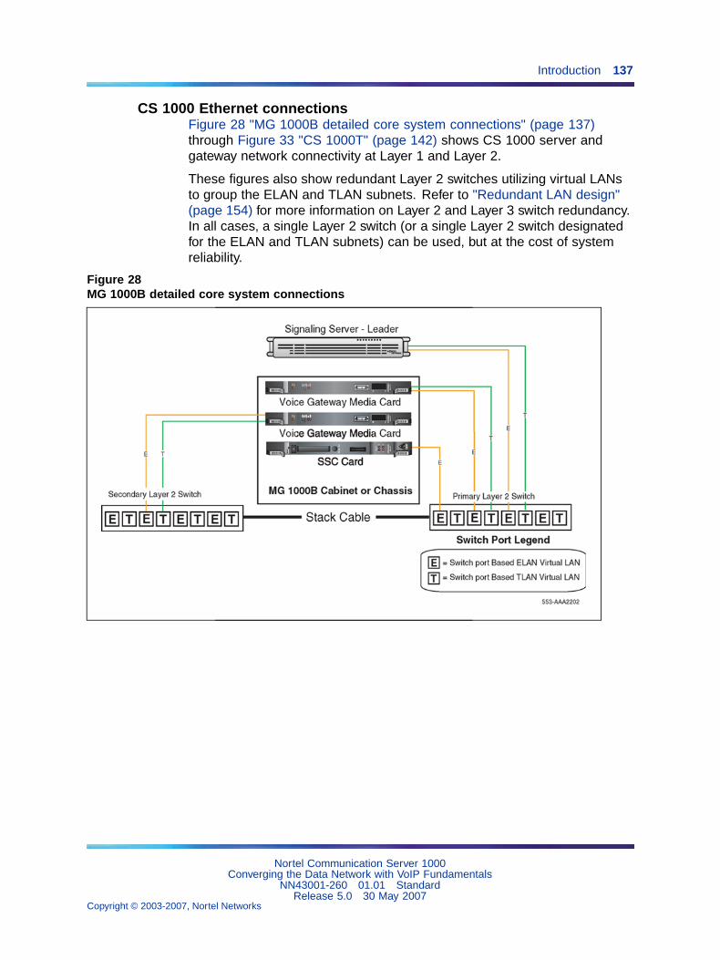
Introduction 137
CS 1000 Ethernet connectionsFigure 28 "MG 1000B detailed core system connections" (page 137)through Figure 33 "CS 1000T" (page 142) shows CS 1000 server andgateway network connectivity at Layer 1 and Layer 2.
These figures also show redundant Layer 2 switches utilizing virtual LANsto group the ELAN and TLAN subnets. Refer to "Redundant LAN design"(page 154) for more information on Layer 2 and Layer 3 switch redundancy.In all cases, a single Layer 2 switch (or a single Layer 2 switch designatedfor the ELAN and TLAN subnets) can be used, but at the cost of systemreliability.
Figure 28MG 1000B detailed core system connections
Nortel Communication Server 1000Converging the Data Network with VoIP Fundamentals
NN43001-260 01.01 StandardRelease 5.0 30 May 2007
Copyright © 2003-2007, Nortel Networks
.
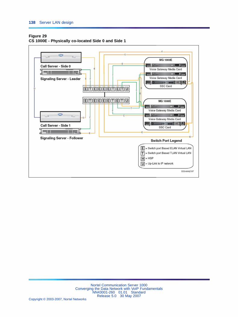
138 Server LAN design
Figure 29CS 1000E - Physically co-located Side 0 and Side 1
Nortel Communication Server 1000Converging the Data Network with VoIP Fundamentals
NN43001-260 01.01 StandardRelease 5.0 30 May 2007
Copyright © 2003-2007, Nortel Networks
.
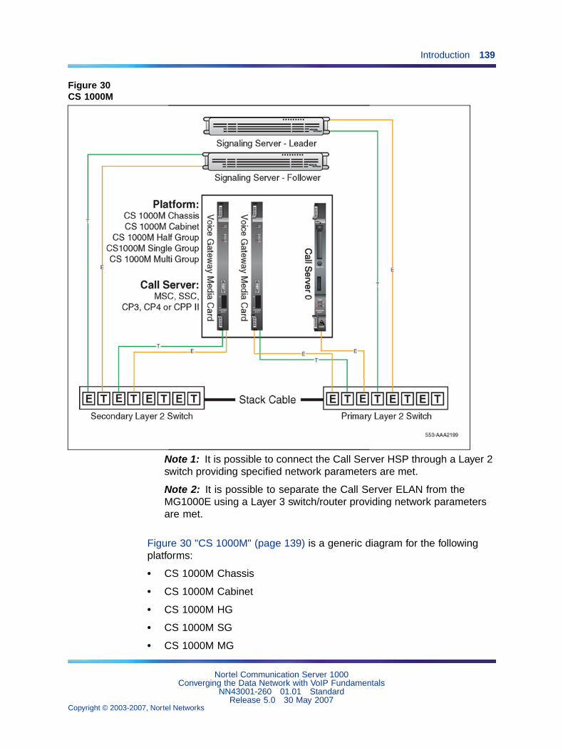
Introduction 139
Figure 30CS 1000M
Note 1: It is possible to connect the Call Server HSP through a Layer 2switch providing specified network parameters are met.
Note 2: It is possible to separate the Call Server ELAN from theMG1000E using a Layer 3 switch/router providing network parametersare met.
Figure 30 "CS 1000M" (page 139) is a generic diagram for the followingplatforms:
• CS 1000M Chassis
• CS 1000M Cabinet
• CS 1000M HG
• CS 1000M SG
• CS 1000M MG
Nortel Communication Server 1000Converging the Data Network with VoIP Fundamentals
NN43001-260 01.01 StandardRelease 5.0 30 May 2007
Copyright © 2003-2007, Nortel Networks
.
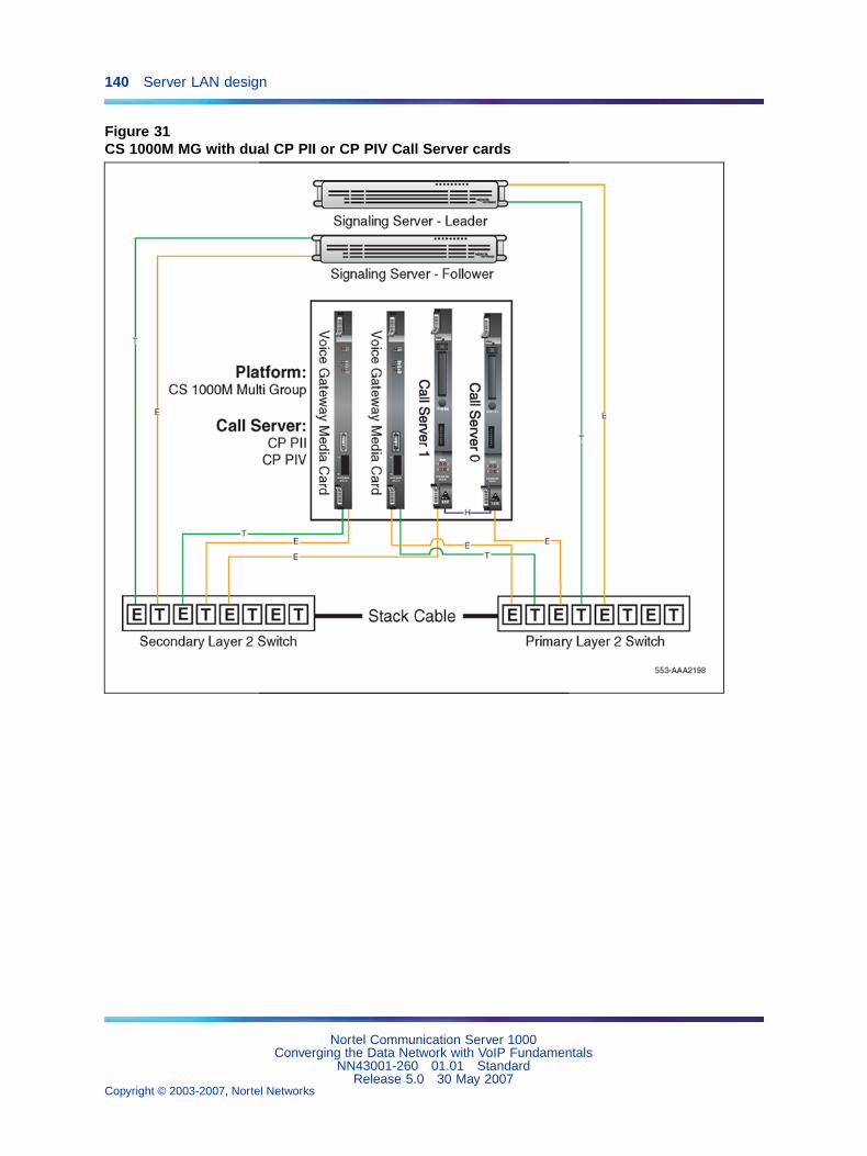
140 Server LAN design
Figure 31CS 1000M MG with dual CP PII or CP PIV Call Server cards
Nortel Communication Server 1000Converging the Data Network with VoIP Fundamentals
NN43001-260 01.01 StandardRelease 5.0 30 May 2007
Copyright © 2003-2007, Nortel Networks
.
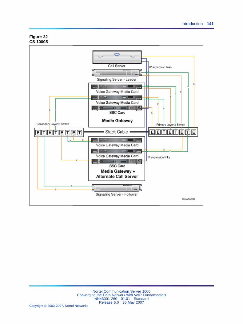
Introduction 141
Figure 32CS 1000S
Nortel Communication Server 1000Converging the Data Network with VoIP Fundamentals
NN43001-260 01.01 StandardRelease 5.0 30 May 2007
Copyright © 2003-2007, Nortel Networks
.
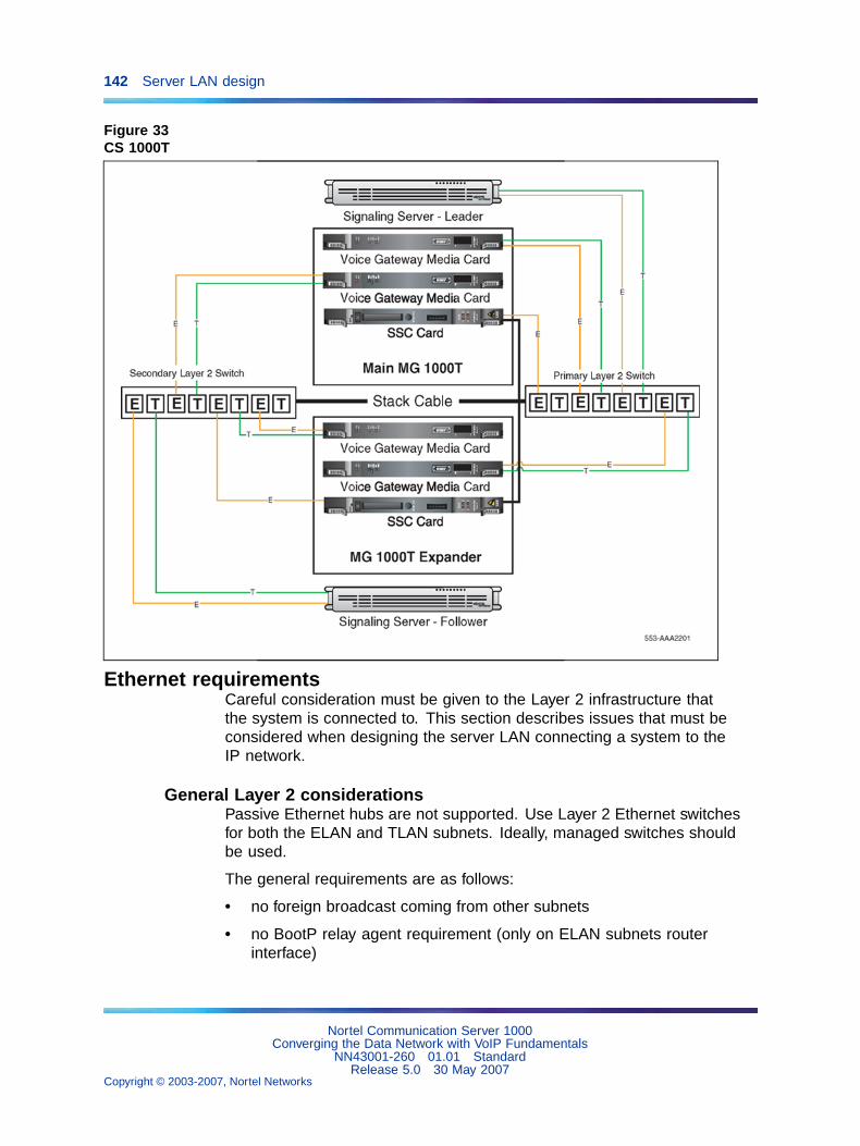
142 Server LAN design
Figure 33CS 1000T
Ethernet requirementsCareful consideration must be given to the Layer 2 infrastructure thatthe system is connected to. This section describes issues that must beconsidered when designing the server LAN connecting a system to theIP network.
General Layer 2 considerationsPassive Ethernet hubs are not supported. Use Layer 2 Ethernet switchesfor both the ELAN and TLAN subnets. Ideally, managed switches shouldbe used.
The general requirements are as follows:
• no foreign broadcast coming from other subnets
• no BootP relay agent requirement (only on ELAN subnets routerinterface)
Nortel Communication Server 1000Converging the Data Network with VoIP Fundamentals
NN43001-260 01.01 StandardRelease 5.0 30 May 2007
Copyright © 2003-2007, Nortel Networks
.
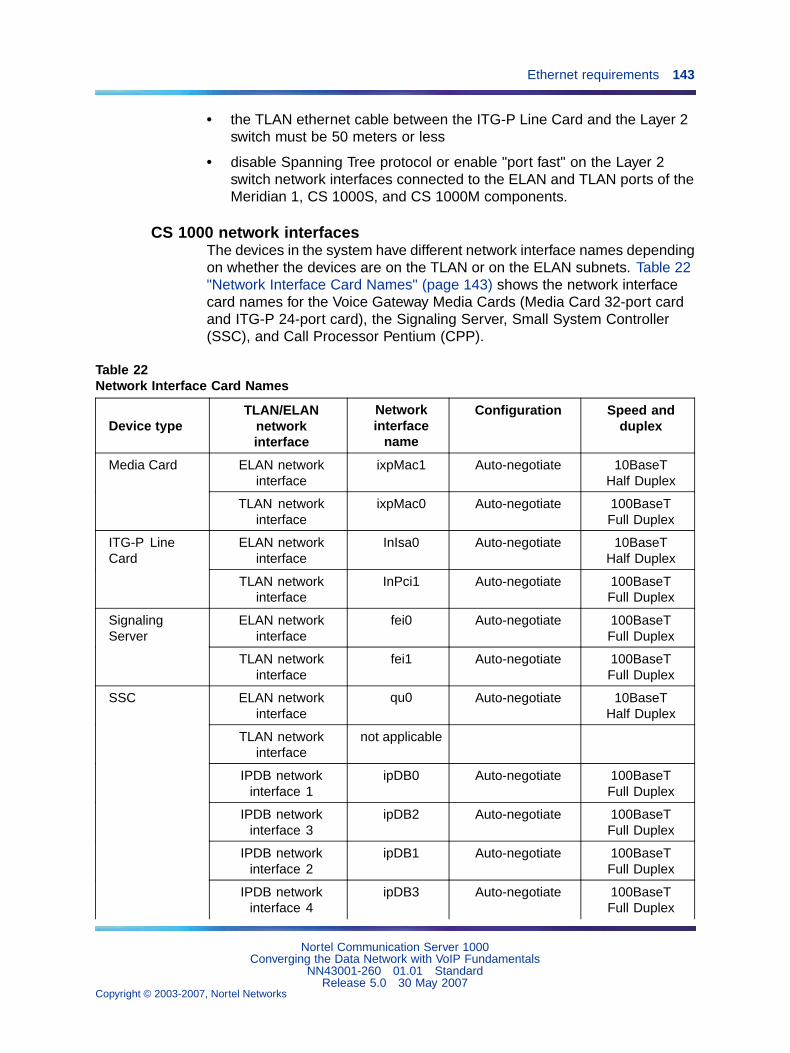
Ethernet requirements 143
• the TLAN ethernet cable between the ITG-P Line Card and the Layer 2switch must be 50 meters or less
• disable Spanning Tree protocol or enable "port fast" on the Layer 2switch network interfaces connected to the ELAN and TLAN ports of theMeridian 1, CS 1000S, and CS 1000M components.
CS 1000 network interfacesThe devices in the system have different network interface names dependingon whether the devices are on the TLAN or on the ELAN subnets. Table 22"Network Interface Card Names" (page 143) shows the network interfacecard names for the Voice Gateway Media Cards (Media Card 32-port cardand ITG-P 24-port card), the Signaling Server, Small System Controller(SSC), and Call Processor Pentium (CPP).
Table 22Network Interface Card Names
Device typeTLAN/ELAN
networkinterface
Networkinterface
name
Configuration Speed andduplex
ELAN networkinterface
ixpMac1 Auto-negotiate 10BaseTHalf Duplex
Media Card
TLAN networkinterface
ixpMac0 Auto-negotiate 100BaseTFull Duplex
ELAN networkinterface
InIsa0 Auto-negotiate 10BaseTHalf Duplex
ITG-P LineCard
TLAN networkinterface
InPci1 Auto-negotiate 100BaseTFull Duplex
ELAN networkinterface
fei0 Auto-negotiate 100BaseTFull Duplex
SignalingServer
TLAN networkinterface
fei1 Auto-negotiate 100BaseTFull Duplex
ELAN networkinterface
qu0 Auto-negotiate 10BaseTHalf Duplex
TLAN networkinterface
not applicable
IPDB networkinterface 1
ipDB0 Auto-negotiate 100BaseTFull Duplex
IPDB networkinterface 3
ipDB2 Auto-negotiate 100BaseTFull Duplex
IPDB networkinterface 2
ipDB1 Auto-negotiate 100BaseTFull Duplex
SSC
IPDB networkinterface 4
ipDB3 Auto-negotiate 100BaseTFull Duplex
Nortel Communication Server 1000Converging the Data Network with VoIP Fundamentals
NN43001-260 01.01 StandardRelease 5.0 30 May 2007
Copyright © 2003-2007, Nortel Networks
.
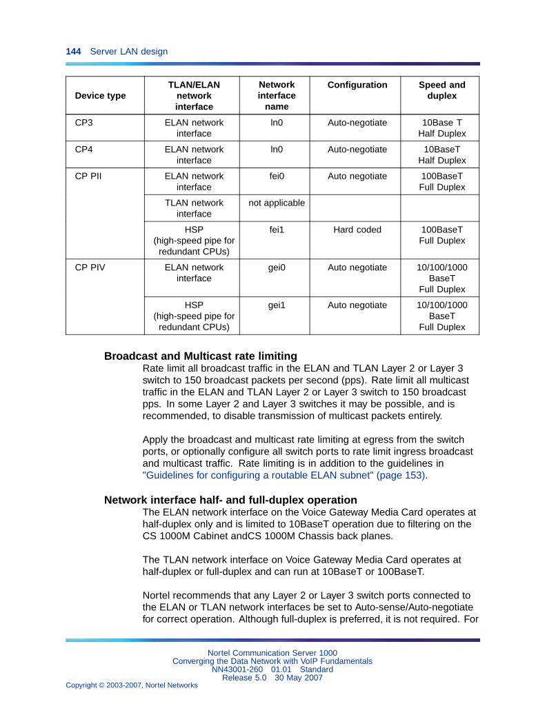
144 Server LAN design
Device typeTLAN/ELAN
networkinterface
Networkinterface
name
Configuration Speed andduplex
CP3 ELAN networkinterface
ln0 Auto-negotiate 10Base THalf Duplex
CP4 ELAN networkinterface
ln0 Auto-negotiate 10BaseTHalf Duplex
ELAN networkinterface
fei0 Auto negotiate 100BaseTFull Duplex
TLAN networkinterface
not applicable
CP PII
HSP(high-speed pipe for
redundant CPUs)
fei1 Hard coded 100BaseTFull Duplex
ELAN networkinterface
gei0 Auto negotiate 10/100/1000BaseT
Full Duplex
CP PIV
HSP(high-speed pipe for
redundant CPUs)
gei1 Auto negotiate 10/100/1000BaseT
Full Duplex
Broadcast and Multicast rate limitingRate limit all broadcast traffic in the ELAN and TLAN Layer 2 or Layer 3switch to 150 broadcast packets per second (pps). Rate limit all multicasttraffic in the ELAN and TLAN Layer 2 or Layer 3 switch to 150 broadcastpps. In some Layer 2 and Layer 3 switches it may be possible, and isrecommended, to disable transmission of multicast packets entirely.
Apply the broadcast and multicast rate limiting at egress from the switchports, or optionally configure all switch ports to rate limit ingress broadcastand multicast traffic. Rate limiting is in addition to the guidelines in"Guidelines for configuring a routable ELAN subnet" (page 153).
Network interface half- and full-duplex operationThe ELAN network interface on the Voice Gateway Media Card operates athalf-duplex only and is limited to 10BaseT operation due to filtering on theCS 1000M Cabinet andCS 1000M Chassis back planes.
The TLAN network interface on Voice Gateway Media Card operates athalf-duplex or full-duplex and can run at 10BaseT or 100BaseT.
Nortel recommends that any Layer 2 or Layer 3 switch ports connected tothe ELAN or TLAN network interfaces be set to Auto-sense/Auto-negotiatefor correct operation. Although full-duplex is preferred, it is not required. For
Nortel Communication Server 1000Converging the Data Network with VoIP Fundamentals
NN43001-260 01.01 StandardRelease 5.0 30 May 2007
Copyright © 2003-2007, Nortel Networks
.
Ethernet requirements 145
example, for the IP Line application, half-duplex has ample bandwidth fora Voice Gateway Media Card with 24 busy channels, VAD disabled, andG.711 CODEC with 10 ms voice range.
Mismatches can occur if devices are hard configured for speed and duplexmode. Every device and port must be correctly configured to avoid duplexmismatch problems that are indicated by lost packets and CRC errors. TheVoice Gateway Media Card cannot be hard-coded for 100BaseT/full-duplexoperation, so the TLAN network interface operates in Auto Negotiate mode.Duplex mismatches and lost packets occur if the TLAN network interfaceis not configured properly.
CAUTIONDuplex mismatches occur in the LAN environment when one sideis set to Auto-negotiate, and the other is hard-configured.
The Auto-negotiate side adapts only to the speed setting of thefixed side. For duplex operations, the Auto-negotiate side setsitself to half-duplex mode. If the forced side is full-duplex, a duplexmismatch occurs.
Spanning Tree options on Layer 2 switchesNortel recommends disabling the Spanning Tree option on the Layer 2switch ports that connect to the TLAN and ELAN network interfaces on theMeridian 1, CS 1000S, and CS 1000M systems.
This option is enabled by default on most Layer 2 switches. If the option isleft enabled, the subsequent Spanning Tree discovery algorithm initiatedwhen a device connected to a port is reset, rebooted, or repowered, caninterfere with the Master Election Process in the Meridian 1, CS 1000S andCS 1000M system devices. In most cases the Master Election Processrecovers from this after a slight delay. However, Nortel recommends thatthe Spanning Tree option on these ports be disabled or the Port Fast optionenabled.
How to avoid system interruptionDuplex mismatchDuplex mismatches can occur in the LAN environment when one side is setto auto-negotiate and the other is hard-configured. The auto-negotiate sideadapts to the fixed-side settings, including speed. For duplex operations,the auto-negotiate side sets itself to half-duplex mode. If the forced side isfull-duplex, a duplex mismatch occurs.
To hard-configure all devices for speed/duplex, ensure every device andport is correctly configured in order to avoid duplex mismatch problems.
Nortel Communication Server 1000Converging the Data Network with VoIP Fundamentals
NN43001-260 01.01 StandardRelease 5.0 30 May 2007
Copyright © 2003-2007, Nortel Networks
.
146 Server LAN design
WARNINGConfigure the Layer 2 or Layer 3 switch ports as Auto-negotiate.
If one side is manually configured and the other side is configuredas Auto-negotiate, the following situation occurs:
The auto-negotiate side sets itself to the manuallyconfigured side’s speed, but always sets itself tohalf-duplex. If the manually-configured side isfull-duplex, then a duplex mismatch occurs and voicequality is unsatisfactory.
Recommendation
Nortel strongly recommends that all Layer 2 ELAN and TLAN switch ports beset to auto-negotiate.
I/O filter connectorThe other major TLAN network interface operation problem arises from thestandard I/O filter connector in IPE modules on Meridian 1 Large Systemsand CS 1000M Large Systems.
Use the following guidelines to avoid system interruption stemming from thestandard I/O filter connector in IPE modules:
• Ensure that the standard IPE module I/O filter is replaced with theprovided Voice Gateway Media Card/ITG-specific filter connector thatremoves filtering from pairs 23 and 24.
• Do not install the Voice Gateway Media Card/ITG-specific filter connectoron top of the standard IPE module I/O filter connector.
• Replace the IPE module backplane I/O ribbon cable assemblies withthose that have interchangeable I/O filter connectors.
• The CAT-5 Ethernet cable from the TLAN network interface to the Layer2 switch port must meet the UTP Category 5 termination and impedanceuniformity standards.
• The CAT-5 Ethernet cable from the TLAN network interface of the ITGPentium card to the Layer 2 switch port must not exceed 50 meters inlength.
The TLAN network interface can auto-negotiate to 100BaseT full-duplex.For the TLAN network interface to operate correctly at 100 Base Tfull-duplex speeds, do the following:
• Install the Voice Gateway Media Card/ITG-specific filter connectorcorrectly by replacing the standard IPE Module I/O filter connector.
Nortel Communication Server 1000Converging the Data Network with VoIP Fundamentals
NN43001-260 01.01 StandardRelease 5.0 30 May 2007
Copyright © 2003-2007, Nortel Networks
.
IP address requirements 147
• Order new IPE Module Backplane I/O ribbon cable assemblies that haveinterchangeable I/O filter connectors if it becomes necessary to use oneof the IPE Modules with molded-on I/O filter connectors.
• Ensure that the UTP cabling is CAT-5 compliant.
• Always keep the CAT-5 Ethernet cable from the TLAN network interfaceto the Layer 2 switch port less than 50 meters for the ITG-Pentium24-port trunk card.
• As an interim measure, connect to each ITG-Pentium 24-port trunkcard and log in to the ITG> shell. In the shell, use the commandstlanDuplexSet and tlanSpeedSet to set the TLAN networkinterface to operate at half-duplex 10BaseT.
IP address requirementsThis section describes IP address requirements for each node, card, and IPPhone.
A node is a group of ITG-P Line Cards and Media Cards in a given Meridian1 or CS 1000 system. Each card in a node has two IP addresses: one forthe TLAN network interface and one for the Meridian 1 or CS 1000 ELANnetwork interface. Each node has one Node IP address on the TLAN subnetthat is dynamically assigned to the connection server on the node Master.The IP Phone uses the Node IP address during the registration process.
All CS 1000 ELAN network interface IP addresses must be on the samesubnet as the system’s Call Server ELAN network interface IP address.
General requirements for node IP addressingThe configure a node, the following IP addresses must be assigned:
• One IP address for each TLAN network interface of every Voice GatewayMedia Card and Signaling Server.
• One IP address for each ELAN network interface of every Voice GatewayMedia Card and Signaling Server.
• One TLAN Node IP address. This alias IP address appears dynamicallyon the TLAN network interface of one card in the node, the Leader ornode Master. This address is shared among all the cards.
• On CS 1000 systems, one IP address for the Signaling Server ELANnetwork interface and Signaling Server TLAN network interface.
In addition to the IP addresses that must be assigned, the following networkinformation must be provided:
• ELAN network interface subnet mask
• ELAN network interface default gateway IP address
Nortel Communication Server 1000Converging the Data Network with VoIP Fundamentals
NN43001-260 01.01 StandardRelease 5.0 30 May 2007
Copyright © 2003-2007, Nortel Networks
.
148 Server LAN design
• TLAN network interface subnet mask
• TLAN network interface default gateway IP address
Note: Use separate ELAN and TLAN subnets with the Voice GatewayMedia card. The user interface provides an option to use the samesubnets, but you must use different subnets.
The default setting of separate ELAN and TLAN subnets protects thesubnet from extraneous network traffic, including broadcast and multicaststorms. It may also protect the Call Server from unauthorized access fromthe customer’s enterprise network.
Recommendation
Nortel strongly recommends using separate dedicated ELAN and TLAN virtualLANs and subnet. They must be separated by a router/Layer 3 switch.
If it is necessary to use a single ELAN and TLAN subnet, see "ELAN and TLANnetwork interfaces on a single subnet" (page 152).
Call Server IP address requirementsThe Call Server IP address is the IP address of the Call Server on theELAN subnet. The Call Server ELAN network interface’s IP addressmust correspond to the Active ELNK IP address configured in LD 117.Specifically:
• one IP address for the Call Server’s ELAN network interface
• two IP addresses for each daughterboard link on a CS 1000M SmallSystem:
— One IP address is on the Call Server.
— The other IP address is on the MG 1000S Small System Controller.
The Alternate Call Server ELAN network interface IP address must be inthe same ELAN subnet as the Primary Call Server ELAN network interfaceIP address
MG 1000E IP address requirementsThe SSC card requires:
• one IP address on the ELAN subnet
• one IP address for the IP daughter network interface connected to theELAN subnet
Nortel Communication Server 1000Converging the Data Network with VoIP Fundamentals
NN43001-260 01.01 StandardRelease 5.0 30 May 2007
Copyright © 2003-2007, Nortel Networks
.
IP address requirements 149
Signaling Server IP address requirementsThe Signaling Server has a TLAN network interface and an ELAN networkinterface, as follows:
• one IP address for the Signaling Server’s ELAN network interface
• one IP address for the Signaling Server’s TLAN network interface
The IP addresses are configured in the Signaling Server Install Tool menu.Follower Signaling Servers are configured using CS 1000 Element Managerrunning on the Leader Signaling Server. For more information about theSignaling Server, refer to Signaling Server Installation and Commissioning(NN43001-312).
Network Routing Service IP address requirementsThe Network Routing Server (NRS) software can be run on a SignalingServer in stand-alone mode with no other applications, or it can run inco-resident mode with other applications such as the Line TPS and MediaGateway 1000T (MG 1000T).
For a standalone NRS, only the TLAN network interface is required. A nodeIP address and a TLAN network interface IP address must be configuredon the standalone NRS. Use of the ELAN network interface is not required.When asked to enter an ELAN IP address, assign a private IP address.For example, 10.10.0.1 with mask 255.255.255.0. Do not configure a CallServer IP address.
For a co-resident NRS, the Signaling Server IP address requirements apply:
• one IP address for the Signaling Server’s ELAN network interface
• one IP address for the Signaling Server’s TLAN network interface
The NRS IP address is the TLAN network interface IP address of theSignaling Server.
The ELAN and TLAN network interface IP addresses, and the NRS IPaddresses, are configured from the Signaling Server Install Tool menu.Follower Signaling Servers are configured using Element Manager runningon the Leader Signaling Server.
Voice Gateway Media Card IP address requirementsProvide an IP address for both the ELAN and TLAN network interfaces. Allcards must be connected to the same ELAN subnet, which is also the samesubnet to which the system’s Call Server is connected. All cards in a nodemust be connected to the same TLAN subnet.
Nortel Communication Server 1000Converging the Data Network with VoIP Fundamentals
NN43001-260 01.01 StandardRelease 5.0 30 May 2007
Copyright © 2003-2007, Nortel Networks
.
150 Server LAN design
The ELAN network interface MAC address corresponds to the ManagementMAC address, which is assigned during manufacturing and cannot bechanged. Locate the faceplate sticker on the Voice Gateway Media Card.The ELAN/Management MAC address is the MOTHERBOARD Ethernetaddress.
The Voice Gateway Media Card IP addresses are configured using ElementManager or TM.
Use separate subnets for the IP Telephony node. Each Voice GatewayMedia Card configuration requires the following:
• Management (ELAN network interface) IP address
• Voice (TLAN network interface) IP address
• Management MAC address
• Voice LAN gateway IP address
ELAN and TLAN subnet configuration examplesThe following restrictions apply:
• The Leader 0 and Leader 1 cards must co-reside on a single TLANsubnet with the Node IP Address.
• Follower cards must reside on the same TLAN subnets.
• All devices must co-reside on the same ELAN subnet as their respectiveCall Server and node leader.
For dual subnet configuration, make sure the TLAN and ELAN subnetsdo not overlap.
Example 1Invalid configuration
The following configuration is not valid, as the TLAN and ELAN subnetsoverlap.
ELAN network interface:
IP address 10.0.0.136
Subnet mask 255.255.255.128
Default Gateway IP address 10.0.0.129
TLAN network interface:
Node IP address 10.0.0.56
IP address 10.0.0.57
Subnet mask 255.255.255.0
Nortel Communication Server 1000Converging the Data Network with VoIP Fundamentals
NN43001-260 01.01 StandardRelease 5.0 30 May 2007
Copyright © 2003-2007, Nortel Networks
.
IP address requirements 151
TLAN network interface:
Default Gateway IP address 10.0.0.1
The range of IP addresses in the ELAN subnet – 10.0.0.129 to 10.0.0.255– overlaps the range of IP addresses in the TLAN subnet – 10.0.0.1 to10.0.0.255. This contravenes the IP addressing practices, as it is equallyvalid to route the IP packets over either interface. The resulting behaviorfrom such a setup is undetermined.
The overlapping IP address scheme must be corrected.
Example 2Valid configuration
The following configuration is valid, as the ELAN and TLAN subnets donot overlap.
The IP addresses can be split as follows.
ELAN network interface:
IP address 10.0.0.136
Subnet mask 255.255.255.128
Default Gateway IP address 10.0.0.129
TLAN network interface:
Node IP address 10.0.0.56
IP address 10.0.0.57
Subnet =mMask 255.255.255.128
Default Gateway IP address 10.0.0.1
The TLAN subnet has a range of addresses from 10.0.0.1 to 10.0.0.127.The ELAN subnet is a separate subnet, with a range of addresses from10.0.0.129 to 10.0.0.255. This configuration results in a smaller TLANsubnet, but it meets the requirement that subnets do not overlap.
Selecting public or private IP addressesThere are a number of factors to consider when determining if the TLANand ELAN subnets will use private (internal) IP addresses or public IPaddresses.
Nortel Communication Server 1000Converging the Data Network with VoIP Fundamentals
NN43001-260 01.01 StandardRelease 5.0 30 May 2007
Copyright © 2003-2007, Nortel Networks
.
152 Server LAN design
Private IP addressesPrivate, or internal, IP addresses are IP addresses that are not routedover the Internet. They can be routed directly between separate intranets,provided that there are no duplicated subnets in the private IP addresses.Private IP addresses can be used to set up the TLAN and ELAN subnets,so that scarce public IP addresses are used efficiently.
Three blocks of IP addresses have been reserved for private intranets:
• 10.0.0.0 – 10.255.255.255
• 172.16.0.0 – 172.31.255.255
• 192.168.0.0 – 192.168.255.255
Some routers and firewalls provide a Network Address Translation (NAT)function that allows the customer to map a registered globally-unique publicIP address to a private IP address without renumbering an existing privateIP address autonomous domain. NAT allows private IP addresses to beaccessed selectively over the Internet.
Public IP addressesPublic IP addresses can be used for the TLAN and ELAN subnets, butconsume limited resources.
This has the same result as the private IP address solution, but the ELANsubnet is accessible from the IP network without NAT.
ELAN and TLAN network interfaces on a single subnetIP Trunk 3.0 (or later) supports the use of a single network interface (forexample, the ELAN network interface). The CS 1000S system does nothave this option.
Single-subnet configuration implies the configuration and use of just onenetwork interface, namely the ELAN network interface, over which all voiceand management traffic is routed. Single-subnet configuration can alsomean configuring both the TLAN and ELAN network interfaces in the samesubnet. Neither configuration is supported. The ELAN and TLAN networkinterfaces must be assigned IP addresses in different subnets.
Separate or dual subnet configuration implies configuration of both theTLAN and ELAN network interfaces. All management and intra-systemsignaling traffic is routed out the ELAN network interface, while all telephonytraffic is routed out the TLAN network interface.
Note: When using separate subnets as recommended, the NetworkActivity LEDs provide useful status information regarding the state ofthe ELAN and TLAN network interfaces. When using an ITG-Pentium24-port trunk card in a single-subnet configuration, all traffic uses the
Nortel Communication Server 1000Converging the Data Network with VoIP Fundamentals
NN43001-260 01.01 StandardRelease 5.0 30 May 2007
Copyright © 2003-2007, Nortel Networks
.
Guidelines for configuring a routable ELAN subnet 153
ELAN network interface. This eliminates the use of the TLAN networkinterface.
Although not recommended, the single-subnet configuration of voice andmanagement could be used in the following situations:
• The combined voice and management traffic on the ELAN subnet is solow that there is no impact on packetized voice QoS performance.
• The customer is willing to tolerate occasional voice quality impairmentscaused by excessive management traffic.
Multiple nodes on the same ELAN and TLAN subnetsThere are several configurations where it is acceptable to put multiple nodeson the same dedicated ELAN and TLAN subnets (separate subnets):
• Several nodes belonging to the same customer and related to the sameCS 1000 Call Server can be configured to route calls with differentCODECs, depending on the digits dialed, or the NCOS of the originatingtelephone. It can also be configured to limit the maximum number ofIP Trunk calls to a particular destination node. The traffic engineeringconsiderations on the TLAN subnet determine how many different nodescan be configured on the same LAN segment.
• Layer 2 (10BaseT or 100Base TX) switching equipment or ATMinfrastructure can support a Virtual LAN (VLAN) segment that isdistributed across a campus or larger corporate network. In this case,some or all of the ITG destination nodes can be on the same subnet.
• In test labs, training centers, and trade shows, it is common fordestination nodes to be located on the same ELAN and TLAN subnets.
Do not place other IP devices, except those designated as acceptable byNortel, on the ELAN or TLAN subnets.
Guidelines for configuring a routable ELAN subnetWhen configuring a routable ELAN subnet on the enterprise IP network,use the following guidelines:
1. External multicasts must not be transmitted on the ELAN subnet.Generally, multicast forwarding is disabled by default on a gatewayrouter. Ensure that no multicast routing protocols are enabled on theELAN subnets gateway router. Do not configure or allow the ELAN orTLAN subnet’s gateway router (that is, the Layer 3 switch) to forwardmulticast traffic to the ELAN subnet.
2. External broadcasts must not be forwarded to the ELAN subnet. Ensurethat the Layer 3 switch is configured so that it does not forward broadcasttraffic from elsewhere on the network to the ELAN subnet. This includesdisabling any features on the Layer 3 switch which forward broadcast
Nortel Communication Server 1000Converging the Data Network with VoIP Fundamentals
NN43001-260 01.01 StandardRelease 5.0 30 May 2007
Copyright © 2003-2007, Nortel Networks
.
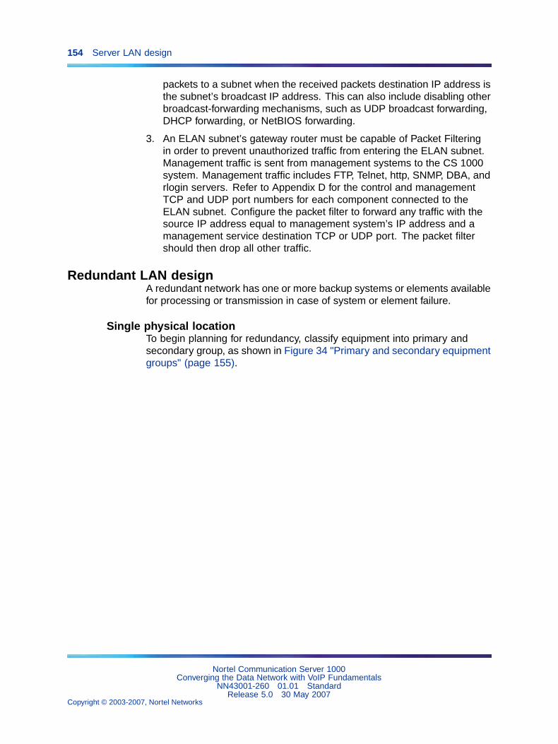
154 Server LAN design
packets to a subnet when the received packets destination IP address isthe subnet’s broadcast IP address. This can also include disabling otherbroadcast-forwarding mechanisms, such as UDP broadcast forwarding,DHCP forwarding, or NetBIOS forwarding.
3. An ELAN subnet’s gateway router must be capable of Packet Filteringin order to prevent unauthorized traffic from entering the ELAN subnet.Management traffic is sent from management systems to the CS 1000system. Management traffic includes FTP, Telnet, http, SNMP, DBA, andrlogin servers. Refer to Appendix D for the control and managementTCP and UDP port numbers for each component connected to theELAN subnet. Configure the packet filter to forward any traffic with thesource IP address equal to management system’s IP address and amanagement service destination TCP or UDP port. The packet filtershould then drop all other traffic.
Redundant LAN designA redundant network has one or more backup systems or elements availablefor processing or transmission in case of system or element failure.
Single physical locationTo begin planning for redundancy, classify equipment into primary andsecondary group, as shown in Figure 34 "Primary and secondary equipmentgroups" (page 155).
Nortel Communication Server 1000Converging the Data Network with VoIP Fundamentals
NN43001-260 01.01 StandardRelease 5.0 30 May 2007
Copyright © 2003-2007, Nortel Networks
.
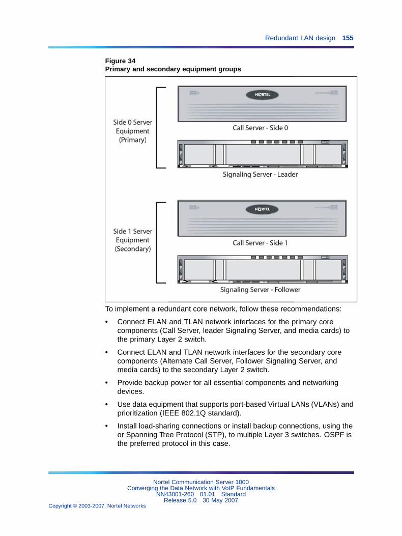
Redundant LAN design 155
Figure 34Primary and secondary equipment groups
To implement a redundant core network, follow these recommendations:
• Connect ELAN and TLAN network interfaces for the primary corecomponents (Call Server, leader Signaling Server, and media cards) tothe primary Layer 2 switch.
• Connect ELAN and TLAN network interfaces for the secondary corecomponents (Alternate Call Server, Follower Signaling Server, andmedia cards) to the secondary Layer 2 switch.
• Provide backup power for all essential components and networkingdevices.
• Use data equipment that supports port-based Virtual LANs (VLANs) andprioritization (IEEE 802.1Q standard).
• Install load-sharing connections or install backup connections, using theor Spanning Tree Protocol (STP), to multiple Layer 3 switches. OSPF isthe preferred protocol in this case.
Nortel Communication Server 1000Converging the Data Network with VoIP Fundamentals
NN43001-260 01.01 StandardRelease 5.0 30 May 2007
Copyright © 2003-2007, Nortel Networks
.
156 Server LAN design
Note: Spanning Tree Protocol convergence can cause Layer 2switch ports to be disabled for up to 60 seconds. This can affectthe entire system.
• If using a highly-available chassis-based system (for example, Passport8100), designate one card as the primary Layer 2 switch and anothercard as the secondary Layer 2 switch. Then, group the ELAN and TLANsubnets with port-based VLANs.
Note: Use of a single highly-available Nortel Passport 8600 switchcan provide a ’five nines’ network.
Figure 35 "Redundant core network – no VLAN on Layer 2 switchinfrastructure" (page 157) to through Figure 37 "MG 1000E redundancydetails" (page 158) starting on page Figure 35 "Redundant core network– no VLAN on Layer 2 switch infrastructure" (page 157) show a networkarchitecture that divides the core components into primary and secondarydevices. Each device is connected to its corresponding Layer 2 switch. Boththe ELAN and TLAN network interfaces are connected to the respectiveLayer 2 switch. VLANs can be used to reduce the number of switchesrequired to obtain a redundant core network.
Figure 35 "Redundant core network – no VLAN on Layer 2 switchinfrastructure" (page 157) show a redundant core network that does notutilize VLANs on the Layer 2 switch infrastructure.
ATTENTIONIMPORTANT!The primary and secondary TLAN network interfaces must be in the same subnetand broadcast domain.
The primary and secondary ELAN network interfaces must be in the same subnetand broadcast domain
Nortel Communication Server 1000Converging the Data Network with VoIP Fundamentals
NN43001-260 01.01 StandardRelease 5.0 30 May 2007
Copyright © 2003-2007, Nortel Networks
.
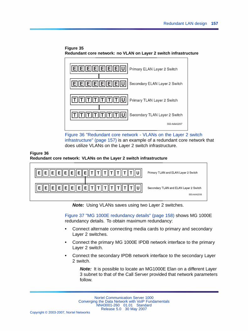
Redundant LAN design 157
Figure 35Redundant core network: no VLAN on Layer 2 switch infrastructure
Figure 36 "Redundant core network - VLANs on the Layer 2 switchinfrastructure" (page 157) is an example of a redundant core network thatdoes utilize VLANs on the Layer 2 switch infrastructure.
Figure 36Redundant core network: VLANs on the Layer 2 switch infrastructure
Note: Using VLANs saves using two Layer 2 switches.
Figure 37 "MG 1000E redundancy details" (page 158) shows MG 1000Eredundancy details. To obtain maximum redundancy:
• Connect alternate connecting media cards to primary and secondaryLayer 2 switches.
• Connect the primary MG 1000E IPDB network interface to the primaryLayer 2 switch.
• Connect the secondary IPDB network interface to the secondary Layer2 switch.
Note: It is possible to locate an MG1000E Elan on a different Layer3 subnet to that of the Call Server provided that network parametersfollow.
Nortel Communication Server 1000Converging the Data Network with VoIP Fundamentals
NN43001-260 01.01 StandardRelease 5.0 30 May 2007
Copyright © 2003-2007, Nortel Networks
.
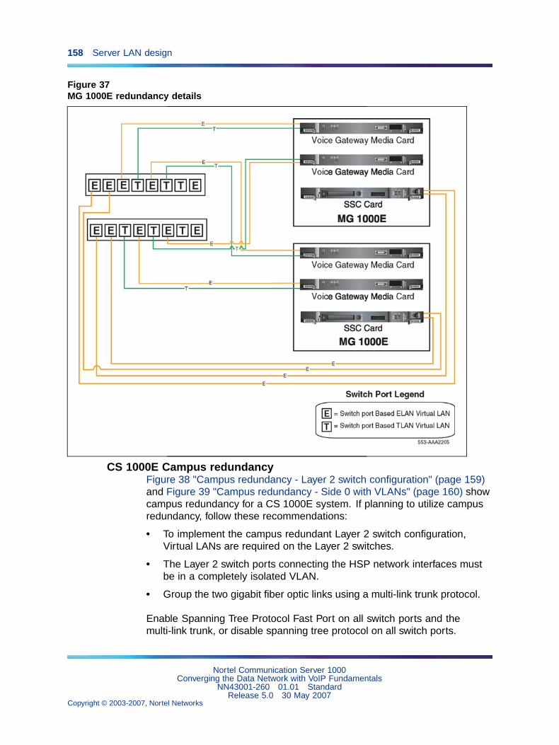
158 Server LAN design
Figure 37MG 1000E redundancy details
CS 1000E Campus redundancyFigure 38 "Campus redundancy - Layer 2 switch configuration" (page 159)and Figure 39 "Campus redundancy - Side 0 with VLANs" (page 160) showcampus redundancy for a CS 1000E system. If planning to utilize campusredundancy, follow these recommendations:
• To implement the campus redundant Layer 2 switch configuration,Virtual LANs are required on the Layer 2 switches.
• The Layer 2 switch ports connecting the HSP network interfaces mustbe in a completely isolated VLAN.
• Group the two gigabit fiber optic links using a multi-link trunk protocol.
Enable Spanning Tree Protocol Fast Port on all switch ports and themulti-link trunk, or disable spanning tree protocol on all switch ports.
Nortel Communication Server 1000Converging the Data Network with VoIP Fundamentals
NN43001-260 01.01 StandardRelease 5.0 30 May 2007
Copyright © 2003-2007, Nortel Networks
.
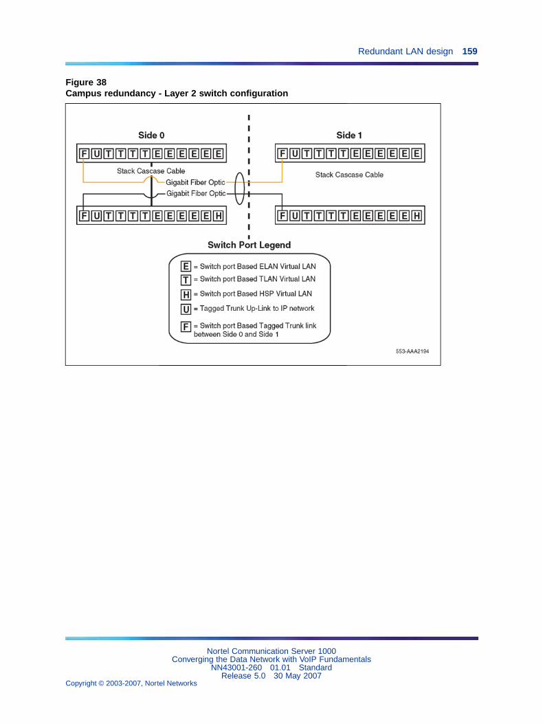
Redundant LAN design 159
Figure 38Campus redundancy - Layer 2 switch configuration
Nortel Communication Server 1000Converging the Data Network with VoIP Fundamentals
NN43001-260 01.01 StandardRelease 5.0 30 May 2007
Copyright © 2003-2007, Nortel Networks
.
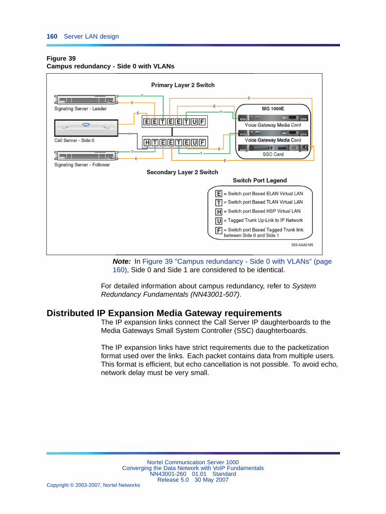
160 Server LAN design
Figure 39Campus redundancy - Side 0 with VLANs
Note: In Figure 39 "Campus redundancy - Side 0 with VLANs" (page160), Side 0 and Side 1 are considered to be identical.
For detailed information about campus redundancy, refer to SystemRedundancy Fundamentals (NN43001-507).
Distributed IP Expansion Media Gateway requirementsThe IP expansion links connect the Call Server IP daughterboards to theMedia Gateways Small System Controller (SSC) daughterboards.
The IP expansion links have strict requirements due to the packetizationformat used over the links. Each packet contains data from multiple users.This format is efficient, but echo cancellation is not possible. To avoid echo,network delay must be very small.
Nortel Communication Server 1000Converging the Data Network with VoIP Fundamentals
NN43001-260 01.01 StandardRelease 5.0 30 May 2007
Copyright © 2003-2007, Nortel Networks
.
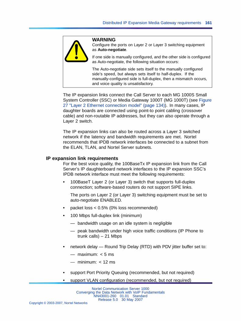
Distributed IP Expansion Media Gateway requirements 161
WARNINGConfigure the ports on Layer 2 or Layer 3 switching equipmentas Auto-negotiate.
If one side is manually configured, and the other side is configuredas Auto-negotiate, the following situation occurs:
The Auto-negotiate side sets itself to the manually configuredside’s speed, but always sets itself to half-duplex. If themanually-configured side is full-duplex, then a mismatch occurs,and voice quality is unsatisfactory.
The IP expansion links connect the Call Server to each MG 1000S SmallSystem Controller (SSC) or Media Gateway 1000T (MG 1000T) (see Figure27 "Layer 2 Ethernet connection model" (page 134)). In many cases, IPdaughter boards are connected using point-to point cabling (crossovercable) and non-routable IP addresses, but they can also operate through aLayer 2 switch.
The IP expansion links can also be routed across a Layer 3 switchednetwork if the latency and bandwidth requirements are met. Nortelrecommends that IPDB network interfaces be connected to a subnet fromthe ELAN, TLAN, and Nortel Server subnets.
IP expansion link requirementsFor the best voice quality, the 100BaseTx IP expansion link from the CallServer’s IP daughterboard network interfaces to the IP expansion SSC’sIPDB network interface must meet the following requirements:
• 100BaseT Layer 2 (or Layer 3) switch that supports full-duplexconnection; software-based routers do not support SIPE links.
The ports on Layer 2 (or Layer 3) switching equipment must be set toauto-negotiate ENABLED.
• packet loss < 0.5% (0% loss recommended)
• 100 Mbps full-duplex link (minimum)
— bandwidth usage on an idle system is negligible
— peak bandwidth under high voice traffic conditions (IP Phone totrunk calls) – 21 Mbps
• network delay — Round Trip Delay (RTD) with PDV jitter buffer set to:
— maximum: < 5 ms
— minimum: < 12 ms
• support Port Priority Queuing (recommended, but not required)
• support VLAN configuration (recommended, but not required)
Nortel Communication Server 1000Converging the Data Network with VoIP Fundamentals
NN43001-260 01.01 StandardRelease 5.0 30 May 2007
Copyright © 2003-2007, Nortel Networks
.
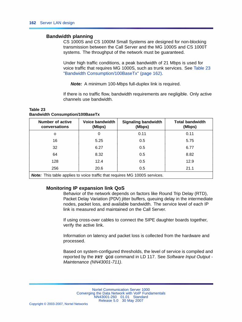
162 Server LAN design
Bandwidth planningCS 1000S and CS 1000M Small Systems are designed for non-blockingtransmission between the Call Server and the MG 1000S and CS 1000Tsystems. The throughput of the network must be guaranteed.
Under high traffic conditions, a peak bandwidth of 21 Mbps is used forvoice traffic that requires MG 1000S, such as trunk services. See Table 23"Bandwidth Consumption/100BaseTx" (page 162).
Note: A minimum 100-Mbps full-duplex link is required.
If there is no traffic flow, bandwidth requirements are negligible. Only activechannels use bandwidth.
Table 23Bandwidth Consumption/100BaseTx
Number of activeconversations
Voice bandwidth(Mbps)
Signaling bandwidth(Mbps)
Total bandwidth(Mbps)
o 0 0.11 0.11
16 5.25 0.5 5.75
32 6.27 0.5 6.77
64 8.32 0.5 8.82
128 12.4 0.5 12.9
256 20.6 0.5 21.1
Note: This table applies to voice traffic that requires MG 1000S services.
Monitoring IP expansion link QoSBehavior of the network depends on factors like Round Trip Delay (RTD),Packet Delay Variation (PDV) jitter buffers, queuing delay in the intermediatenodes, packet loss, and available bandwidth. The service level of each IPlink is measured and maintained on the Call Server.
If using cross-over cables to connect the SIPE daughter boards together,verify the active link.
Information on latency and packet loss is collected from the hardware andprocessed.
Based on system-configured thresholds, the level of service is compiled andreported by the PRT QOS command in LD 117. See Software Input Output -Maintenance (NN43001-711).
Nortel Communication Server 1000Converging the Data Network with VoIP Fundamentals
NN43001-260 01.01 StandardRelease 5.0 30 May 2007
Copyright © 2003-2007, Nortel Networks
.
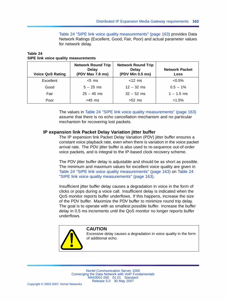
Distributed IP Expansion Media Gateway requirements 163
Table 24 "SIPE link voice quality measurements" (page 163) provides DataNetwork Ratings (Excellent, Good, Fair, Poor) and actual parameter valuesfor network delay.
Table 24SIPE link voice quality measurements
Voice QoS Rating
Network Round TripDelay
(PDV Max 7.8 ms)
Network Round TripDelay
(PDV Min 0.5 ms)Network Packet
Loss
Excellent <5 ms <12 ms <0.5%
Good 5 – 25 ms 12 – 32 ms 0.5 – 1%
Fair 25 – 45 ms 32 – 52 ms 1 – 1.5 ms
Poor >45 ms >52 ms >1.5%
The values in Table 24 "SIPE link voice quality measurements" (page 163)assume that there is no echo cancellation mechanism and no particularmechanism for recovering lost packets.
IP expansion link Packet Delay Variation jitter bufferThe IP expansion link Packet Delay Variation (PDV) jitter buffer ensures aconstant voice playback rate, even when there is variation in the voice packetarrival rate. The PDV jitter buffer is also used to re-sequence out-of-ordervoice packets, and is integral to the IP-based clock recovery scheme.
The PDV jitter buffer delay is adjustable and should be as short as possible.The minimum and maximum values for excellent voice quality are given inTable 24 "SIPE link voice quality measurements" (page 163) on Table 24"SIPE link voice quality measurements" (page 163).
Insufficient jitter buffer delay causes a degradation in voice in the form ofclicks or pops during a voice call. Insufficient delay is indicated when theQoS monitor reports buffer underflows. If this happens, increase the sizeof the PDV buffer. Maximize the PDV buffer to minimize round trip delay.The goal is to operate with as smallest possible buffer. Increase the bufferdelay in 0.5 ms increments until the QoS monitor no longer reports bufferunderflows.
CAUTIONExcessive delay causes a degradation in voice quality in the formof additional echo.
Nortel Communication Server 1000Converging the Data Network with VoIP Fundamentals
NN43001-260 01.01 StandardRelease 5.0 30 May 2007
Copyright © 2003-2007, Nortel Networks
.
164 Server LAN design
Note: Echo cancellers must be installed wherever the IP networkinterfaces with a TDM network that uses a 2-wire device, such as ananalog loop device.
The command PRT PDV in LD 117 displays both the current size of the PDVbuffer and the number of PDV underflows.
In addition, a warning message is printed when a parameter threshold(or combination of thresholds) is reached. These thresholds are not userconfigurable.
The command CHG PDV in LD 117 is used to set PDV buffer size on aper-link basis. The command should be run initially using default settings.Then increase its delay parameter in 0.5 ms increments if an unacceptablelevel of voice quality occurs (pops and clicks). Decrease this value if echooccurs. The goal is to have with the smallest jitter buffer possible.
The PDV jitter buffer size for each IP expansion link is configured at the CallServer and is automatically downloaded to the MG 1000S.
For detailed information on these commands, refer to Software Input Output- Maintenance (NN43001-711).
Distributed Media Gateway 1000EA Media Gateway 1000E (MG 1000E) can be physically distributed withinan enterprise IP network, providing the following criteria are met:
• IPMG’s IPDB network interfaces must be connected to the same ELANsubnet as the CS 1000E Call Server.
• Media Cards in the physically-distributed MG 1000E must be connectedto the same ELAN subnet as the CS 1000E Call Server. A Layer 2virtual LAN-enabled campus network architecture can be used toaccomplish this.
• Packet loss on the enterprise IP network must be less than 0.5% (0%packet loss is recommended).
• Round-trip delay between Call Server and MG 1000E must be less than80 ms.
• Use of a QoS mechanism is highly recommended and assists in meetingpacket loss and latency requirements.
Campus-distributed Media Gateway enhancementsThe Media Gateway enhancement allows the Campus Media Gateway1000E to be on a separate subnet from the Call Server and traverse a Layer3 routing protocol, and enables the Campus Media Gateway 1000E to use
Nortel Communication Server 1000Converging the Data Network with VoIP Fundamentals
NN43001-260 01.01 StandardRelease 5.0 30 May 2007
Copyright © 2003-2007, Nortel Networks
.
Campus-distributed Media Gateway enhancements 165
any Layer 2 switch. The Campus Redundancy enhancement enables theELAN network interface connections of the various nodes to reside ondifferent subnets. Therefore, the following is no longer necessary:
• Signaling Server ELAN network interface IP address to reside on thesame subnet as the IP address of the Voice Gateway Media Card’sELAN network interface
• Call Server IP address (ELAN network interface) to reside on the samesubnet as the IP address of the Voice Gateway Media Card’s ELANnetwork interface
This enhancement also changes the operation of the ELAN subnet betweenthe Call Server and the Media Gateway 1000Es. It allows the MediaGateway 1000Es to be on a different subnet than the Call Server.
Previously, the installation of Media Gateway 1000Es required that the ELANsubnet and broadcast domain be extended to any Media Gateway 1000Einstalled in the campus, exposing the Call Server subnet to Layer 2 traffic,including broadcasts, from the customer network. Signaling to the VoiceGateway Media Card ELAN network interfaces requires this VLAN, due tomessages that are broadcast to all devices on the ELAN subnet; specifically,the messages sent after a warm start or cold start are broadcast over theELAN subnet to inform all devices how to handle their existing media pathsand connections. Signaling to the Small System Controller (SSC) of theMedia Gateway 1000E does not require such a VLAN connection, sincethese messages are provided using Layer 3 IP routing.
This enhancement propagates the SSC messages for warm start and coldstart to all devices within the SSC’s broadcast domain, if the subnet of theSSC is different than that of the Call Server. This allows the Voice GatewayMedia Card ELAN network interfaces to receive this information withouthaving a VLAN connection back to the Call Server.
The Media Gateway enhancement provides the additional functionality toseparate the Call Server/Signaling Server ELAN subnet from the MediaGateway 1000E through a Layer 3 routing protocol. See Figure 40 "MediaGateway separation from the Call Server by Layer 3 router" (page 166).
Nortel Communication Server 1000Converging the Data Network with VoIP Fundamentals
NN43001-260 01.01 StandardRelease 5.0 30 May 2007
Copyright © 2003-2007, Nortel Networks
.
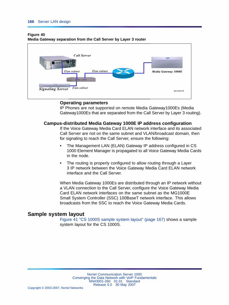
166 Server LAN design
Figure 40Media Gateway separation from the Call Server by Layer 3 router
Operating parametersIP Phones are not supported on remote Media Gateway1000Es (MediaGateway1000Es that are separated from the Call Server by Layer 3 routing).
Campus-distributed Media Gateway 1000E IP address configurationIf the Voice Gateway Media Card ELAN network interface and its associatedCall Server are not on the same subnet and VLAN/broadcast domain, thenfor signaling to reach the Call Server, ensure the following:
• The Management LAN (ELAN) Gateway IP address configured in CS1000 Element Manager is propagated to all Voice Gateway Media Cardsin the node.
• The routing is properly configured to allow routing through a Layer3 IP network between the Voice Gateway Media Card ELAN networkinterface and the Call Server.
When Media Gateway 1000Es are distributed through an IP network withouta VLAN connection to the Call Server, configure the Voice Gateway MediaCard ELAN network interfaces on the same subnet as the MG1000ESmall System Controller (SSC) 100BaseT network interface. This allowsbroadcasts from the SSC to reach the Voice Gateway Media Cards.
Sample system layoutFigure 41 "CS 1000S sample system layout" (page 167) shows a samplesystem layout for the CS 1000S.
Nortel Communication Server 1000Converging the Data Network with VoIP Fundamentals
NN43001-260 01.01 StandardRelease 5.0 30 May 2007
Copyright © 2003-2007, Nortel Networks
.
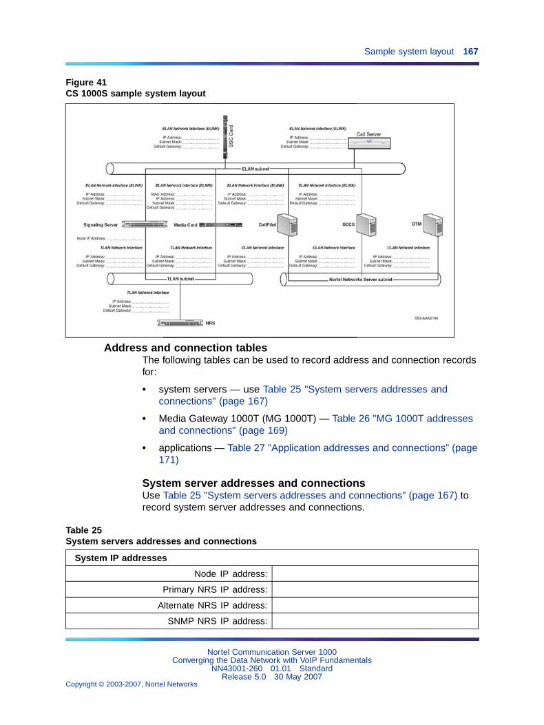
Sample system layout 167
Figure 41CS 1000S sample system layout
Address and connection tablesThe following tables can be used to record address and connection recordsfor:
• system servers — use Table 25 "System servers addresses andconnections" (page 167)
• Media Gateway 1000T (MG 1000T) — Table 26 "MG 1000T addressesand connections" (page 169)
• applications — Table 27 "Application addresses and connections" (page171)
System server addresses and connectionsUse Table 25 "System servers addresses and connections" (page 167) torecord system server addresses and connections.
Table 25System servers addresses and connections
System IP addresses
Node IP address:
Primary NRS IP address:
Alternate NRS IP address:
SNMP NRS IP address:
Nortel Communication Server 1000Converging the Data Network with VoIP Fundamentals
NN43001-260 01.01 StandardRelease 5.0 30 May 2007
Copyright © 2003-2007, Nortel Networks
.
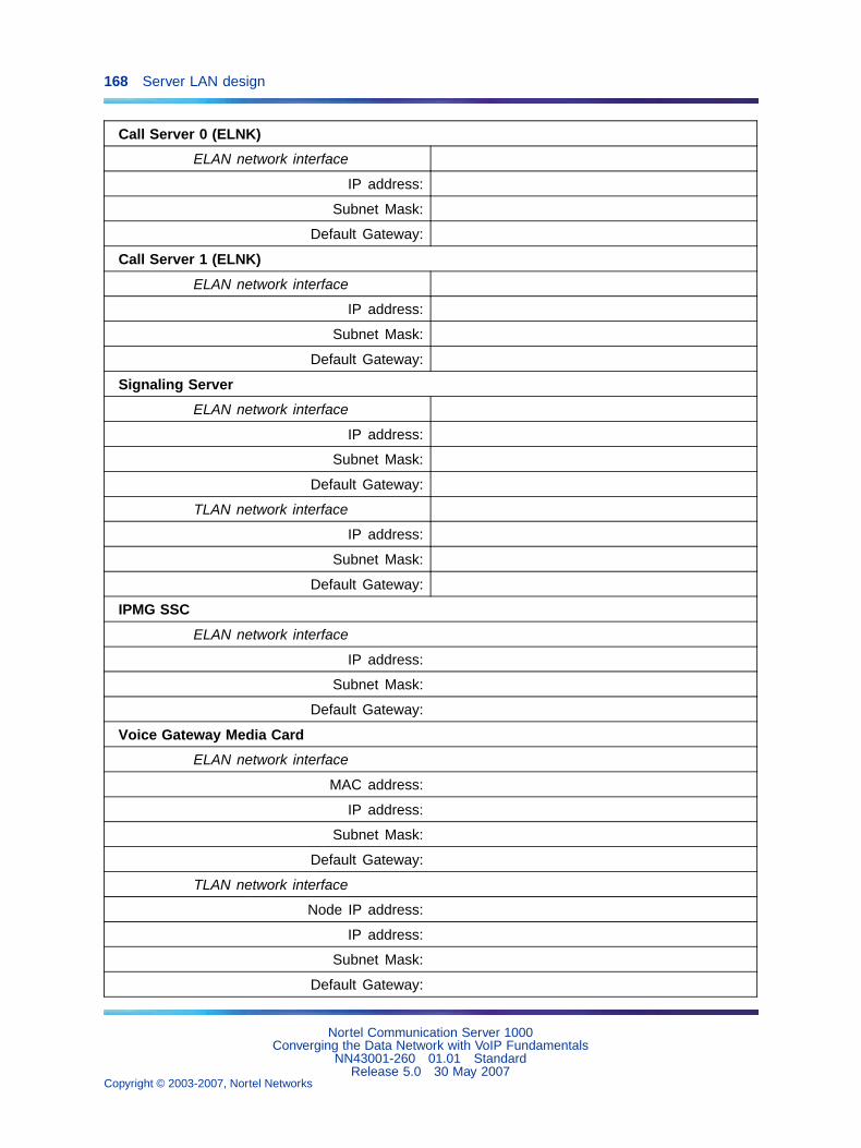
168 Server LAN design
Call Server 0 (ELNK)
ELAN network interface
IP address:
Subnet Mask:
Default Gateway:
Call Server 1 (ELNK)
ELAN network interface
IP address:
Subnet Mask:
Default Gateway:
Signaling Server
ELAN network interface
IP address:
Subnet Mask:
Default Gateway:
TLAN network interface
IP address:
Subnet Mask:
Default Gateway:
IPMG SSC
ELAN network interface
IP address:
Subnet Mask:
Default Gateway:
Voice Gateway Media Card
ELAN network interface
MAC address:
IP address:
Subnet Mask:
Default Gateway:
TLAN network interface
Node IP address:
IP address:
Subnet Mask:
Default Gateway:
Nortel Communication Server 1000Converging the Data Network with VoIP Fundamentals
NN43001-260 01.01 StandardRelease 5.0 30 May 2007
Copyright © 2003-2007, Nortel Networks
.
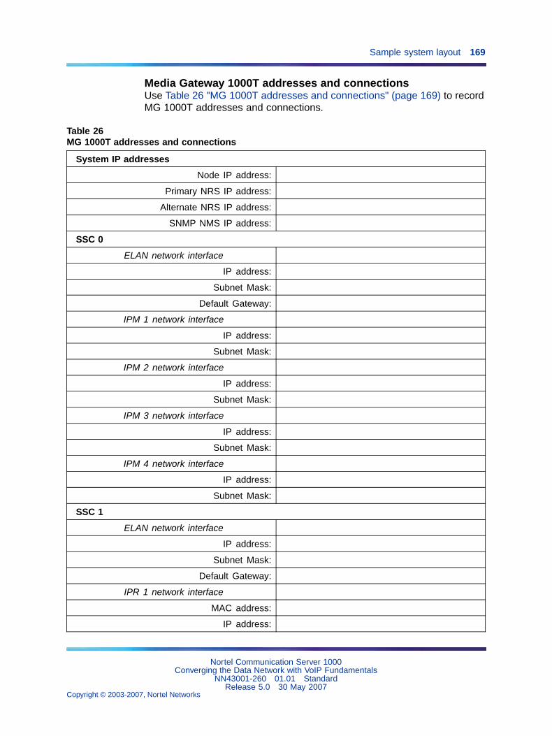
Sample system layout 169
Media Gateway 1000T addresses and connectionsUse Table 26 "MG 1000T addresses and connections" (page 169) to recordMG 1000T addresses and connections.
Table 26MG 1000T addresses and connections
System IP addresses
Node IP address:
Primary NRS IP address:
Alternate NRS IP address:
SNMP NMS IP address:
SSC 0
ELAN network interface
IP address:
Subnet Mask:
Default Gateway:
IPM 1 network interface
IP address:
Subnet Mask:
IPM 2 network interface
IP address:
Subnet Mask:
IPM 3 network interface
IP address:
Subnet Mask:
IPM 4 network interface
IP address:
Subnet Mask:
SSC 1
ELAN network interface
IP address:
Subnet Mask:
Default Gateway:
IPR 1 network interface
MAC address:
IP address:
Nortel Communication Server 1000Converging the Data Network with VoIP Fundamentals
NN43001-260 01.01 StandardRelease 5.0 30 May 2007
Copyright © 2003-2007, Nortel Networks
.
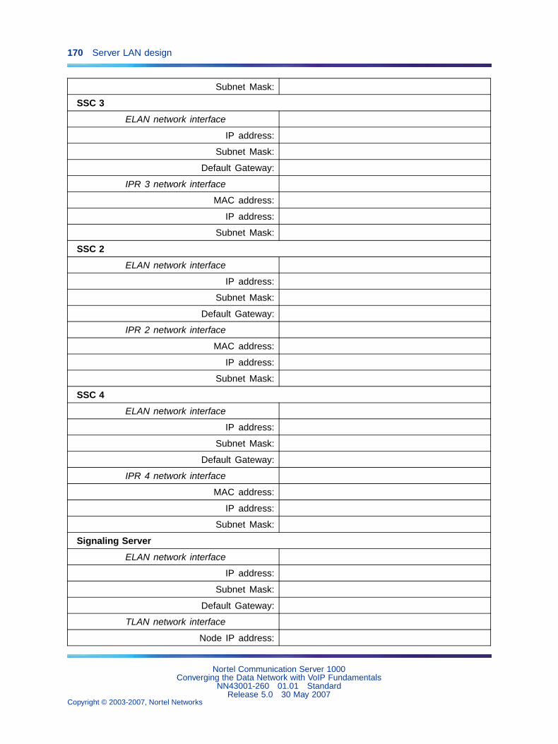
170 Server LAN design
Subnet Mask:
SSC 3
ELAN network interface
IP address:
Subnet Mask:
Default Gateway:
IPR 3 network interface
MAC address:
IP address:
Subnet Mask:
SSC 2
ELAN network interface
IP address:
Subnet Mask:
Default Gateway:
IPR 2 network interface
MAC address:
IP address:
Subnet Mask:
SSC 4
ELAN network interface
IP address:
Subnet Mask:
Default Gateway:
IPR 4 network interface
MAC address:
IP address:
Subnet Mask:
Signaling Server
ELAN network interface
IP address:
Subnet Mask:
Default Gateway:
TLAN network interface
Node IP address:
Nortel Communication Server 1000Converging the Data Network with VoIP Fundamentals
NN43001-260 01.01 StandardRelease 5.0 30 May 2007
Copyright © 2003-2007, Nortel Networks
.
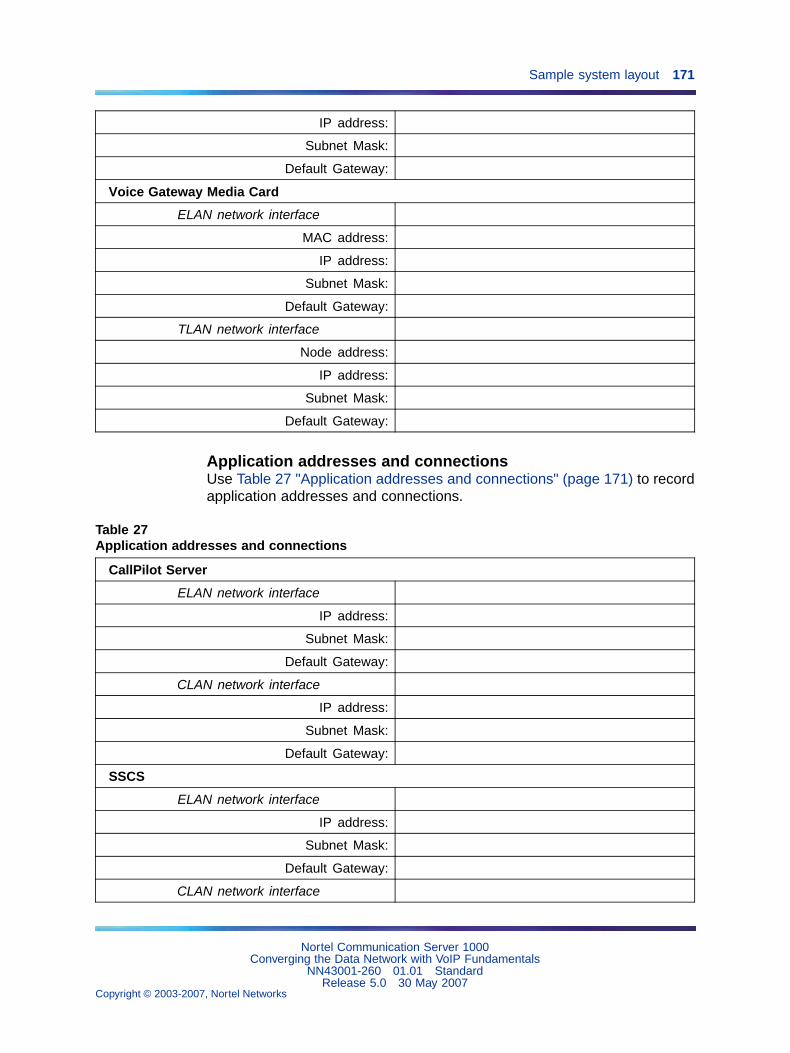
Sample system layout 171
IP address:
Subnet Mask:
Default Gateway:
Voice Gateway Media Card
ELAN network interface
MAC address:
IP address:
Subnet Mask:
Default Gateway:
TLAN network interface
Node address:
IP address:
Subnet Mask:
Default Gateway:
Application addresses and connectionsUse Table 27 "Application addresses and connections" (page 171) to recordapplication addresses and connections.
Table 27Application addresses and connections
CallPilot Server
ELAN network interface
IP address:
Subnet Mask:
Default Gateway:
CLAN network interface
IP address:
Subnet Mask:
Default Gateway:
SSCS
ELAN network interface
IP address:
Subnet Mask:
Default Gateway:
CLAN network interface
Nortel Communication Server 1000Converging the Data Network with VoIP Fundamentals
NN43001-260 01.01 StandardRelease 5.0 30 May 2007
Copyright © 2003-2007, Nortel Networks
.
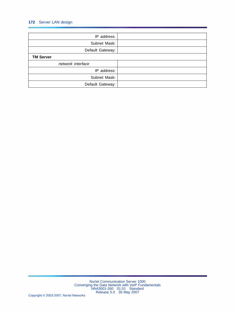
172 Server LAN design
IP address:
Subnet Mask:
Default Gateway:
TM Server
network interface
IP address:
Subnet Mask:
Default Gateway:
Nortel Communication Server 1000Converging the Data Network with VoIP Fundamentals
NN43001-260 01.01 StandardRelease 5.0 30 May 2007
Copyright © 2003-2007, Nortel Networks
.
173
Configuration of the DHCP server
ContentsThis section contains information on the following topics:
"Overview" (page 173)
"IP Phones" (page 174)
"Partial DHCP mode" (page 174)
"Full DHCP mode" (page 174)
"802.1Q configuration of IP Phones" (page 175)
"Configuring the DHCP server to support full DHCP mode" (page 175)
"IP Phone class identifier" (page 175)
"Requested network configuration parameters" (page 176)
"Format for IP Phone DHCP Class Identifier option" (page 177)
"Format for IP Phone DHCP encapsulated Vendor Specific Option" (page177)
"Format for IP Phone DHCP site-specific option" (page 183)
OverviewThis chapter provides general guidelines on how to configure a host with aDynamic Host Configuration Protocol (DHCP) server to support Nortel IPPhones 200x and the IP Softphone 2050.
Note 1: If not familiar with DHCP, Nortel recommends reading Requestfor Comments (RFC) 2131 "Dynamic Host Configuration Protocol", RFC1533 "DHCP Options and BOOTP Vendor Extensions", and the Helpmanual for the DHCP server on the host.
Note 2: For a general overview of DHCP server technology, refer toAppendix "DHCP supplemental information" (page 231).
Nortel Communication Server 1000Converging the Data Network with VoIP Fundamentals
NN43001-260 01.01 StandardRelease 5.0 30 May 2007
Copyright © 2003-2007, Nortel Networks
.
174 Configuration of the DHCP server
IP PhonesIP Phones 200x and the IP Softphone 2050 are VoIP telephones thatfunction as a telephone to the Meridian 1 and CS 1000 systems. TheIP Phone encodes voice as binary data and packetizes the data fortransmission over an IP network to the Voice Gateway Media Card or toanother IP Phone.
The Nortel IP Phone can act as a DHCP client in one of two modes:
• partial DHCP mode
• full DHCP mode
All the configuration parameters for the IP Phone can be entered manually.Each IP Phone requires the network configuration parameters, ConnectServer parameters, IP Telephony node ID, and Virtual TN. If there are anumber of IP Phones to configure, manual configuration is time-consumingand prone to error. Using full or partial DHCP to automatically configurethe IP Phones is more efficient and flexible. This ensures that currentinformation is used.
Partial DHCP modeWhen the IP Phone is configured to operate in partial DHCP mode, theDHCP server needs no special configuration to support IP Phones. TheIP Phone receives the following network configuration parameters fromthe DHCP server:
• IP address configuration for the IP Phone
• subnet mask for the IP Phone IP address
• default gateway for the IP Phone LAN segment
Note: In partial DHCP mode the Connect Server parameters, node IDand Virtual TN must be entered manually.
Full DHCP modeIn full DHCP mode, the DHCP server requires special configuration. TheIP Phone obtains network configuration parameters and Connect Serverconfiguration parameters from specially-configured DHCP servers.
The following parameters are provided for the primary and secondaryConnect Servers:
• Connect Server IP address — for IP Line 4.5, the Connect Server IPaddress is the IP Telephony node IP address.
• port number = 4100
• command value = 1; identifies the request to the Connect Server asoriginating from an IP Phone
Nortel Communication Server 1000Converging the Data Network with VoIP Fundamentals
NN43001-260 01.01 StandardRelease 5.0 30 May 2007
Copyright © 2003-2007, Nortel Networks
.
Configuring the DHCP server to support full DHCP mode 175
• retry count = 10 (typically)
Note: The IP Telephony node ID and Virtual TN must always beconfigured manually even in full DHCP mode.
802.1Q configuration of IP Phones802.1Q VLAN support is configured using the display interface of the IPPhones during the initial configuration procedure of the IP Phone.
For 802.1Q configuration procedures of the IP Phones, see IP PhonesFundamentals (NN43001-368).
Configuring the DHCP server to support full DHCP modeThe DHCP capability of the IP Phone enables the telephone to receivenetwork configuration parameters and specific Connect Server parameters.This section describes the IP Phone’s unique class identifier and requestednetwork configuration and Connect Server parameters for automaticconfiguration.
IP Phone class identifierThe IP Phone is designed with a unique class identifier that the DHCPserver can use to identify the telephone. All Nortel IP Phones use thesame text string, Nortel-i2004-A. The ASCII string is sent inside the ClassIdentifier option of the IP Phone’s DHCP messages.
The DHCP server also includes this string in its responses to the IP PhoneDHCP client. This makes it possible to notify the IP Phone that the server isIP Phone-aware, and that it is safe to accept the server’s offer. This stringappears in the beginning of a list of specific Voice Gateway Media Cardinformation that the IP Phone DHCP client requests.
When the DHCP server is configured to recognize the IP Phone as a specialclass, the DHCP server can treat the IP Phone differently than other DHCPclients. DHCP host configuration parameters can then be grouped by classto supply only information relevant to the IP Phone DHCP client, such as theConnect Server parameters. The administrator can also design the networkaccording to the client’s class, if necessary, making maintenance easier.
Depending on the capabilities and limitations of the DHCP server usedand the design of the network, some of these advanced functions are notavailable.
Nortel Communication Server 1000Converging the Data Network with VoIP Fundamentals
NN43001-260 01.01 StandardRelease 5.0 30 May 2007
Copyright © 2003-2007, Nortel Networks
.
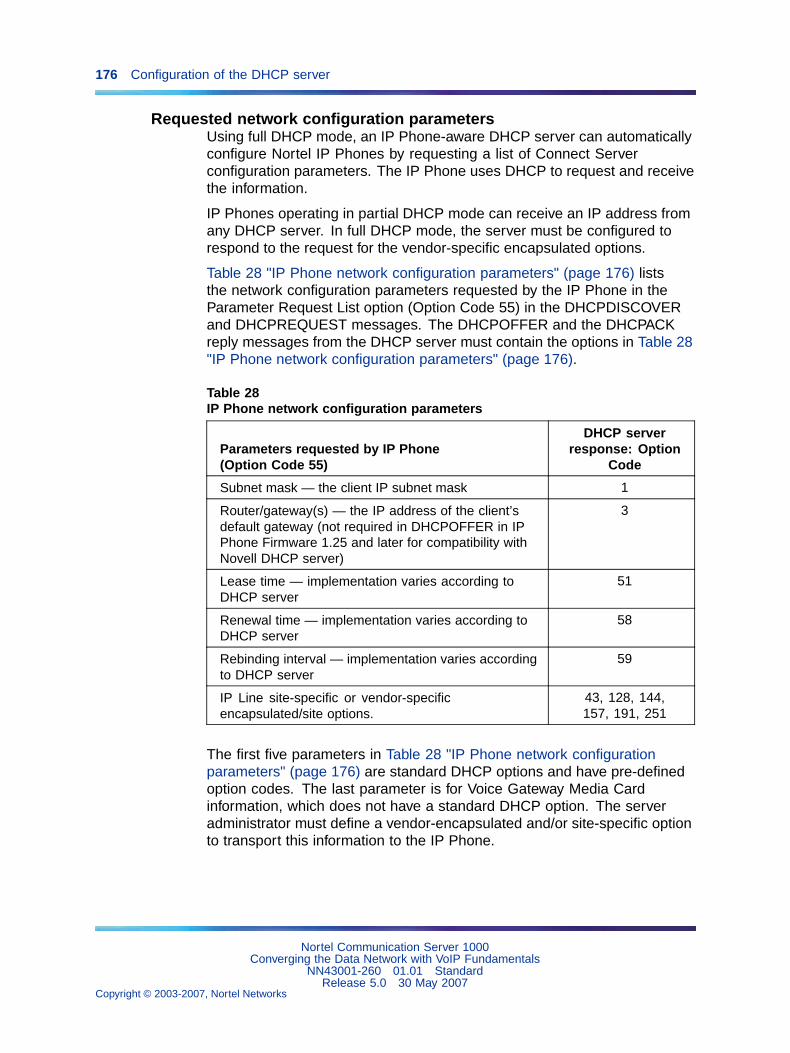
176 Configuration of the DHCP server
Requested network configuration parametersUsing full DHCP mode, an IP Phone-aware DHCP server can automaticallyconfigure Nortel IP Phones by requesting a list of Connect Serverconfiguration parameters. The IP Phone uses DHCP to request and receivethe information.
IP Phones operating in partial DHCP mode can receive an IP address fromany DHCP server. In full DHCP mode, the server must be configured torespond to the request for the vendor-specific encapsulated options.
Table 28 "IP Phone network configuration parameters" (page 176) liststhe network configuration parameters requested by the IP Phone in theParameter Request List option (Option Code 55) in the DHCPDISCOVERand DHCPREQUEST messages. The DHCPOFFER and the DHCPACKreply messages from the DHCP server must contain the options in Table 28"IP Phone network configuration parameters" (page 176).
Table 28IP Phone network configuration parameters
Parameters requested by IP Phone(Option Code 55)
DHCP serverresponse: Option
Code
Subnet mask — the client IP subnet mask 1
Router/gateway(s) — the IP address of the client’sdefault gateway (not required in DHCPOFFER in IPPhone Firmware 1.25 and later for compatibility withNovell DHCP server)
3
Lease time — implementation varies according toDHCP server
51
Renewal time — implementation varies according toDHCP server
58
Rebinding interval — implementation varies accordingto DHCP server
59
IP Line site-specific or vendor-specificencapsulated/site options.
43, 128, 144,157, 191, 251
The first five parameters in Table 28 "IP Phone network configurationparameters" (page 176) are standard DHCP options and have pre-definedoption codes. The last parameter is for Voice Gateway Media Cardinformation, which does not have a standard DHCP option. The serveradministrator must define a vendor-encapsulated and/or site-specific optionto transport this information to the IP Phone.
Nortel Communication Server 1000Converging the Data Network with VoIP Fundamentals
NN43001-260 01.01 StandardRelease 5.0 30 May 2007
Copyright © 2003-2007, Nortel Networks
.
Configuring the DHCP server to support full DHCP mode 177
This non-standard information includes the unique string identifying the IPPhone and the Connect Server parameters for the primary and secondaryservers. The IP Phone must receive the Connect Server parameters toconnect to the IP Telephony node.
The administrator must use one of the site-specific or vendor-encapsulatedoption codes to implement the Voice Gateway Media Card information. Thisuser-defined option can then be sent as-is, or encapsulated in a VendorEncapsulated option with Option Code 43. The method used depends onthe DHCP server’s capabilities and what options are already in use by othervendors.
The IP Phone rejects any DHCPOFFER and DHCPACK messages thatdo not contain the following options:
• a router option — IP Phone requires a default gateway (router)
• a subnet mask option
• a vendor-specific option (see Note 1) or a site-specific option (see Note2)
Note 1: The vendor-specific option code is 43. A Windows NTDHCP Server (up to SR4) supports only 16 octets of data for thevendor-specific option, which is insufficient to support the minimumlength of the IP Phone-specific string. If using a Windows NTDHCP Server, select the Site Specific option to accommodate theIP Phone-specific string.
Note 2: The site-specific options are all DHCP options between 128(0x80) and 254 (0xFE). These options are reserved for site-specificuse by the DHCP RFCs.
Format for IP Phone DHCP Class Identifier optionAll Nortel IP Phones fill in the Class ID option of the DHCPDISCOVER andDHCPREQUEST messages with the null-terminated, ASCII-encoded stringNortel-i2004-A, where A identifies the version number of the informationformat of the IP Phone.
The Class Identifier Nortel-i2004-A must be unique in the DHCP serverdomain.
Format for IP Phone DHCP encapsulated Vendor Specific OptionThe following definition describes the Nortel-specific, encapsulated VendorSpecific Option for IP Phones 200x and the IP Softphone 2050. This optionmust be encapsulated in a DHCP vendor-specific option (refer to RFC1533) and returned by the DHCP server as part of each DHCPOFFER andDHCPACK message for the IP Phone to accept these messages as valid.The IP Phone extracts the relevant information from this option and uses
Nortel Communication Server 1000Converging the Data Network with VoIP Fundamentals
NN43001-260 01.01 StandardRelease 5.0 30 May 2007
Copyright © 2003-2007, Nortel Networks
.
178 Configuration of the DHCP server
it to configure the Connect Server IP address, the port number (4100), acommand value (1), and the retry count for the primary and secondaryConnect Servers.
Either this encapsulated Vendor Specific Option or a similarly encodedsite-specific option must be sent. The DHCP server must be configured tosend one or the other, but not both. The choice of using the vendor-specificor the site-specific option is provided to enable Windows NT DHCP serversto support the IP Phone. Windows NT servers do not properly implementthe Vendor Specific Option, and as a result, Windows NT implementationsmust use the Site Specific version.
The format of the encapsulated Vendor Specific option is Type, Length, andData, described in the following sections.
Type (1 octet):There are five types:
• 0x80 (Site Specific option 128)
• 0x90 (Site Specific option 144)
• 0x9d (Site Specific option 157)
• 0xbf (Site Specific option 191)
• 0xfb (Site Specific option 251)
The choice of five types enables the IP Phone to work one or more valuesare already in use by a different vendor. Select one value for the Type byte.
Length (1 octet)The Length value is variable. Count only the number of octets in the datafield (see the next section "Data (variable number of octets)" (page 178)).
Data (variable number of octets)The Data field contains an ASCII-encoded character string as follows:
Nortel-i20xx-A,iii.jjj.kkk.lll:ppppp,aaa,rrr;iii.jjj.kkk.lll:ppppp,aaa,rrr.
This string can be NULL-terminated, although the NULL is not requiredfor parsing.
Nortel Communication Server 1000Converging the Data Network with VoIP Fundamentals
NN43001-260 01.01 StandardRelease 5.0 30 May 2007
Copyright © 2003-2007, Nortel Networks
.
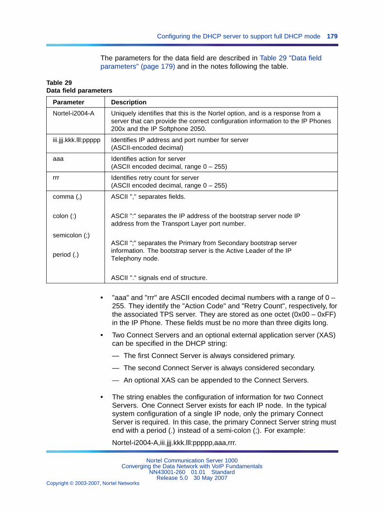
Configuring the DHCP server to support full DHCP mode 179
The parameters for the data field are described in Table 29 "Data fieldparameters" (page 179) and in the notes following the table.
Table 29Data field parameters
Parameter Description
Nortel-i2004-A Uniquely identifies that this is the Nortel option, and is a response from aserver that can provide the correct configuration information to the IP Phones200x and the IP Softphone 2050.
iii.jjj.kkk.lll:ppppp Identifies IP address and port number for server(ASCII-encoded decimal)
aaa Identifies action for server(ASCII encoded decimal, range 0 – 255)
rrr Identifies retry count for server(ASCII encoded decimal, range 0 – 255)
comma (,)
colon (:)
semicolon (;)
period (.)
ASCII "," separates fields.
ASCII ":" separates the IP address of the bootstrap server node IPaddress from the Transport Layer port number.
ASCII ";" separates the Primary from Secondary bootstrap serverinformation. The bootstrap server is the Active Leader of the IPTelephony node.
ASCII "." signals end of structure.
• "aaa" and "rrr" are ASCII encoded decimal numbers with a range of 0 –255. They identify the "Action Code" and "Retry Count", respectively, forthe associated TPS server. They are stored as one octet (0x00 – 0xFF)in the IP Phone. These fields must be no more than three digits long.
• Two Connect Servers and an optional external application server (XAS)can be specified in the DHCP string:
— The first Connect Server is always considered primary.
— The second Connect Server is always considered secondary.
— An optional XAS can be appended to the Connect Servers.
• The string enables the configuration of information for two ConnectServers. One Connect Server exists for each IP node. In the typicalsystem configuration of a single IP node, only the primary ConnectServer is required. In this case, the primary Connect Server string mustend with a period (.) instead of a semi-colon (;). For example:
Nortel-i2004-A,iii.jjj.kkk.lll:ppppp,aaa,rrr.
Nortel Communication Server 1000Converging the Data Network with VoIP Fundamentals
NN43001-260 01.01 StandardRelease 5.0 30 May 2007
Copyright © 2003-2007, Nortel Networks
.
180 Configuration of the DHCP server
If the secondary Connect Server portion of the string is specified, thenthe string information is typically the same as the primary ConnectServer information. For example:
Nortel-i2004-A,iii.jjj.kkk.lll:ppppp,aaa,rrr;iii.jjj.kkk.lll:ppppp,aaa,rrr.
When the ’Enhanced Redundancy for IP Line Nodes’ feature is used,two different Connect Server strings can be configured, separated with asemi-colon (;). This enables the telephone to register to two differentnodes. For more information about the Enhanced Redundancy for IPLine Nodes feature, refer to IP Line Fundamentals (NN43100-500).
• Action code values:
— 0 — reserved
— 1 — UNIStim Hello (currently this type is the only valid choice)
— 2 – 254 — reserved
— 255 — reserved
• iii.jjj.kkk.lll are ASCII-encoded decimal numbers representing the IPaddress of the server. They do not need to be three digits long becausethe . and : delimiters guarantee parsing. For example, ’001’, ’01’, and ’1’would be parsed correctly and interpreted as value 0x01 internal to theIP Phone. These fields must be no longer than three digits.
• ppppp is the port number in ASCII-encoded decimal. It does not needto be five digits long as the : and , delimiters guarantee parsing. Forexample, ’05001’, ’5001’, ’1’, ’00001’ would be parsed correctly andaccepted as correct. The valid range is 0-65535 (stored internally inthe IP Phone as hexadecimal in range 0 – 0xFFFF). This field must beno longer than five digits.
• In all cases, the ASCII-encoded numbers are treated as decimal valuesand all leading zeros are ignored. Specifically, a leading zero doesnot change the interpretation of the value to be OCTAL-encoded. Forexample, 0021, 021, and 21 are all parsed and interpreted as decimal21.
• When using the Full DHCP option on the IP Phone 2004, the IP addressof an XAS can be provided. To do this, append the XAS IP addressand port to the Nortel DHCP option currently used to specify the firstand second server IP address, ports, and retry and action codes. ForGraphical XAS, the action code (aaa) and retry count (rrr) must beappended. For Text XAS, it is not necessary to append these values.
The format of the exchange application server’s IP address and port is:
iii.jjj.kkk.lll:ppppp,aaa,rrr
Nortel Communication Server 1000Converging the Data Network with VoIP Fundamentals
NN43001-260 01.01 StandardRelease 5.0 30 May 2007
Copyright © 2003-2007, Nortel Networks
.
Configuring the DHCP server to support full DHCP mode 181
The XAS port action code (aaa) byte values are:
— 1=Graphical XAS
— 0=Text XAS
The port field is processed if Graphical XAS is selected, but ignored forText XAS (the fixed text port is used). XAS always uses port 5000.
Note: If the XAS port action code (aaa) byte value is 0 (Text XAS),then the port action code and retry count fields are not required. Ifthe XAS port action code (aaa) byte value is 1 (Graphical XAS), thenthe port action code and retry count fields are not optional and mustbe included in the configuration string.
For example, the format of the option used to specify Connect Server 1,Connect Server 2, and the exchange application server (XAS), wherethe XAS port action code (aaa) byte value is 1 (Graphical XAS) is:
Nortel-i20xx-A,iii.jjj.kkk.lll:ppppp,aaa,rrr;iii.jjj.kkk.lll:ppppp,aaa,rrr;iii.jjj.kkk.lll:ppppp,aaa,rrr.
If the XAS port action code (aaa) byte value is 0 (Text XAS), the formatof the option used to specify Connect Server 1 , Connect Server 2, andthe exchange application server (XAS) is:
Nortel-i20xx-A,iii.jjj.kkk.lll:ppppp,aaa,rrr;iii.jjj.kkk.lll:ppppp,aaa,rrr;iii.jjj.kkk.lll:ppppp
Refer to the following section "Configuration string examples" (page 181) foradditional examples.
Configuration string examplesTable 30 "Configuration string for one Connect Server" (page 182) to Table35 "Configuration string for two Connect Servers and an XAS (Graphical)"(page 183) shows configuration strings with one or more Connect Serversand exchange application servers. The following conventions are used:
• The Nortel Class Identifier is separated from the servers by a comma (,).
• The servers are separated by semi-colons (;).
• The IP address and port numbers are separated by a colon (:).
Nortel Communication Server 1000Converging the Data Network with VoIP Fundamentals
NN43001-260 01.01 StandardRelease 5.0 30 May 2007
Copyright © 2003-2007, Nortel Networks
.
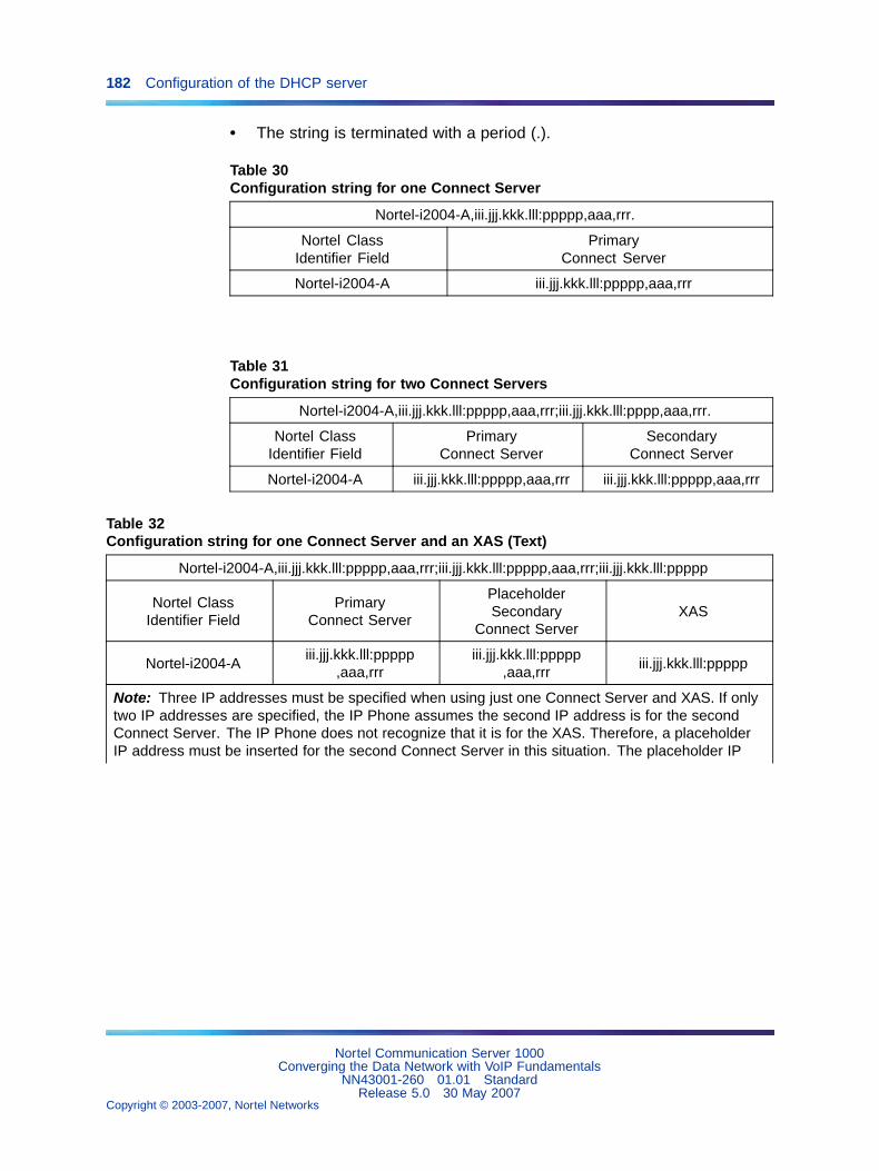
182 Configuration of the DHCP server
• The string is terminated with a period (.).
Table 30Configuration string for one Connect Server
Nortel-i2004-A,iii.jjj.kkk.lll:ppppp,aaa,rrr.
Nortel ClassIdentifier Field
PrimaryConnect Server
Nortel-i2004-A iii.jjj.kkk.lll:ppppp,aaa,rrr
Table 31Configuration string for two Connect Servers
Nortel-i2004-A,iii.jjj.kkk.lll:ppppp,aaa,rrr;iii.jjj.kkk.lll:pppp,aaa,rrr.
Nortel ClassIdentifier Field
PrimaryConnect Server
SecondaryConnect Server
Nortel-i2004-A iii.jjj.kkk.lll:ppppp,aaa,rrr iii.jjj.kkk.lll:ppppp,aaa,rrr
Table 32Configuration string for one Connect Server and an XAS (Text)
Nortel-i2004-A,iii.jjj.kkk.lll:ppppp,aaa,rrr;iii.jjj.kkk.lll:ppppp,aaa,rrr;iii.jjj.kkk.lll:ppppp
Nortel ClassIdentifier Field
PrimaryConnect Server
PlaceholderSecondary
Connect ServerXAS
Nortel-i2004-Aiii.jjj.kkk.lll:ppppp
,aaa,rrriii.jjj.kkk.lll:ppppp
,aaa,rrriii.jjj.kkk.lll:ppppp
Note: Three IP addresses must be specified when using just one Connect Server and XAS. If onlytwo IP addresses are specified, the IP Phone assumes the second IP address is for the secondConnect Server. The IP Phone does not recognize that it is for the XAS. Therefore, a placeholderIP address must be inserted for the second Connect Server in this situation. The placeholder IP
Nortel Communication Server 1000Converging the Data Network with VoIP Fundamentals
NN43001-260 01.01 StandardRelease 5.0 30 May 2007
Copyright © 2003-2007, Nortel Networks
.
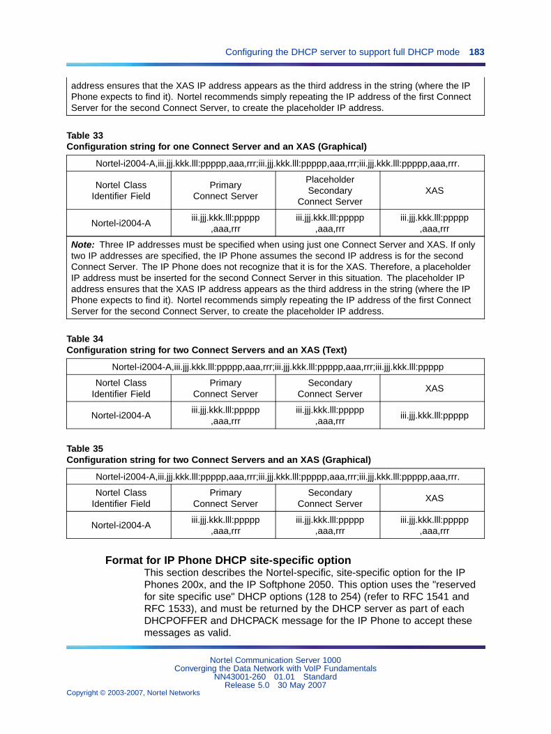
Configuring the DHCP server to support full DHCP mode 183
address ensures that the XAS IP address appears as the third address in the string (where the IPPhone expects to find it). Nortel recommends simply repeating the IP address of the first ConnectServer for the second Connect Server, to create the placeholder IP address.
Table 33Configuration string for one Connect Server and an XAS (Graphical)
Nortel-i2004-A,iii.jjj.kkk.lll:ppppp,aaa,rrr;iii.jjj.kkk.lll:ppppp,aaa,rrr;iii.jjj.kkk.lll:ppppp,aaa,rrr.
Nortel ClassIdentifier Field
PrimaryConnect Server
PlaceholderSecondary
Connect ServerXAS
Nortel-i2004-Aiii.jjj.kkk.lll:ppppp
,aaa,rrriii.jjj.kkk.lll:ppppp
,aaa,rrriii.jjj.kkk.lll:ppppp
,aaa,rrr
Note: Three IP addresses must be specified when using just one Connect Server and XAS. If onlytwo IP addresses are specified, the IP Phone assumes the second IP address is for the secondConnect Server. The IP Phone does not recognize that it is for the XAS. Therefore, a placeholderIP address must be inserted for the second Connect Server in this situation. The placeholder IPaddress ensures that the XAS IP address appears as the third address in the string (where the IPPhone expects to find it). Nortel recommends simply repeating the IP address of the first ConnectServer for the second Connect Server, to create the placeholder IP address.
Table 34Configuration string for two Connect Servers and an XAS (Text)
Nortel-i2004-A,iii.jjj.kkk.lll:ppppp,aaa,rrr;iii.jjj.kkk.lll:ppppp,aaa,rrr;iii.jjj.kkk.lll:ppppp
Nortel ClassIdentifier Field
PrimaryConnect Server
SecondaryConnect Server
XAS
Nortel-i2004-Aiii.jjj.kkk.lll:ppppp
,aaa,rrriii.jjj.kkk.lll:ppppp
,aaa,rrriii.jjj.kkk.lll:ppppp
Table 35Configuration string for two Connect Servers and an XAS (Graphical)
Nortel-i2004-A,iii.jjj.kkk.lll:ppppp,aaa,rrr;iii.jjj.kkk.lll:ppppp,aaa,rrr;iii.jjj.kkk.lll:ppppp,aaa,rrr.
Nortel ClassIdentifier Field
PrimaryConnect Server
SecondaryConnect Server
XAS
Nortel-i2004-Aiii.jjj.kkk.lll:ppppp
,aaa,rrriii.jjj.kkk.lll:ppppp
,aaa,rrriii.jjj.kkk.lll:ppppp
,aaa,rrr
Format for IP Phone DHCP site-specific optionThis section describes the Nortel-specific, site-specific option for the IPPhones 200x, and the IP Softphone 2050. This option uses the "reservedfor site specific use" DHCP options (128 to 254) (refer to RFC 1541 andRFC 1533), and must be returned by the DHCP server as part of eachDHCPOFFER and DHCPACK message for the IP Phone to accept thesemessages as valid.
Nortel Communication Server 1000Converging the Data Network with VoIP Fundamentals
NN43001-260 01.01 StandardRelease 5.0 30 May 2007
Copyright © 2003-2007, Nortel Networks
.
184 Configuration of the DHCP server
The IP Phone retrieves the relevant information and uses it to configure theIP address for the primary TPS and optional secondary TPS. Either thissite-specific option must be present or a similarly encoded vendor-specificoption must be sent. That is, configure the DHCP server to send one or theother but not both. The choice of using either vendor-specific or site-specificoptions enables Windows NT DHCP servers to be used with the IP Phone.Windows NT servers do not properly implement the vendor-specific optionand as a result, Windows NT implementations must use the site-specificversion.
The format of the option is Type, Length, and Data. The format of the sameas that of the encapsulated vendor-specific option (see "Format for IPPhone DHCP encapsulated Vendor Specific Option" (page 177)).
Nortel Communication Server 1000Converging the Data Network with VoIP Fundamentals
NN43001-260 01.01 StandardRelease 5.0 30 May 2007
Copyright © 2003-2007, Nortel Networks
.
185
Operating the VoIP network
ContentsThis section contains information on the following topics:
"System management" (page 185)
"TM" (page 185)
"Element Manager" (page 186)
"Network monitoring" (page 187)
"Set VoIP QoS objectives" (page 187)
"Intranet QoS monitoring" (page 188)
"ITG Operational Measurements" (page 189)
"OM report description" (page 190)
"User feedback" (page 190)
"QoS monitoring and reporting tools" (page 190)
"Network Diagnostic Utilities" (page 191)
"Proactive Voice Quality Management" (page 199)
"Network Management" (page 207)
"SNMP Network Management Systems" (page 207)
"TM and Network Management System" (page 208)
"Policy Management" (page 208)
"CS 1000 network inventory and configuration" (page 209)
System managementThe system can be managed using Telephony Manager (TM) or CS 1000ElementManager.
TMTelephony Manager (TM) is an integrated suite of system managementtools. Compatible with a standard PC, it provides a single point of accessand control to manage the systems.
Nortel Communication Server 1000Converging the Data Network with VoIP Fundamentals
NN43001-260 01.01 StandardRelease 5.0 30 May 2007
Copyright © 2003-2007, Nortel Networks
.
186 Operating the VoIP network
TM uses IP technology to target the following:
• single point of connectivity to the system and related devices
• data collection for traffic and billing records
• collection, processing, distribution, and notification of alarms and events
• data propagation
• performance measurement tools (Traffic Analysis package, andReal-time Conferencing Protocol (RTCP) statistics from the TerminalProxy Server (TPS) and Voice Gateway Media Cards)
• web-based management applications, including security
TM can be integrated with the suite of Optivity management tools to providecomprehensive management of the voice and data network.
For more information about TM, refer to Telephony Manager3.1 Installationand Commissioning (NN43050-300) or Telephony Manager 3.1 SystemAdministration (NN43050-601)
Element ManagerElement Manager is a simple and user-friendly web-based interface thatsupports a broad range of system management tasks, including:
• configuration and maintenance of IP Peer and IP telephony features
• configuration and maintenance of traditional routes and trunks
• configuration and maintenance of numbering plans
• configuration of Call Server data blocks (such as configuration data,customer data, Common Equipment data, D-channels)
• maintenance commands, system status inquiries, backup and restorefunctions
• software download, patch download, patch activation
Element Manager has many features to help administrators managesystems with greater efficiency. Examples are as follows:
• Web pages provide a single point-of-access to parameters that weretraditionally available through multiple overlays.
• Parameters are presented in logical groups to increase ease-of-useand speed-of-access.
• The hide or show information option enables administrators to seeinformation that relates directly to the task at hand.
• Full-text descriptions of parameters and acronyms help administratorsreduce configuration errors.
Nortel Communication Server 1000Converging the Data Network with VoIP Fundamentals
NN43001-260 01.01 StandardRelease 5.0 30 May 2007
Copyright © 2003-2007, Nortel Networks
.
Network monitoring 187
• Configuration screens offer pre-selected defaults, drop-down lists,checkboxes, and range values to simplify response selection.
The Element Manager web server resides on the Signaling Server and canbe accessed directly through a web browser or Telephony Manager (TM).The TM navigator includes integrated links to each network system andtheir respective instances of Element Manager.
For more information on using Element Manager, refer to TelephonyManager 3.1 System Administration (NN43050-601).
Network monitoringThe network design process is ongoing, continuing after implementation ofthe VoIP network and commissioning of voice services over the network.Network changes VoIP traffic, general intranet traffic patterns, networkpolicies, network topology, user expectations, and networking technologycan render a design obsolete or non-compliant with QoS objectives. Reviewthe design periodically against prevailing and trended network conditionsand traffic patterns, at least once every two to three weeks initially, thenon a quarterly basis.
It is assumed that the customer’s organization already has processes inplace to monitor, analyze, and re-design both the Meridian CustomerDefined Network (MCDN) and the corporate intranet, so that both networkscontinue to conform to internal QoS standards. When operating VoIPservices, the customer’s organization must incorporate additional monitoringand planning processes, such as:
• Collect, analyze, and trend VoIP traffic patterns.
• Monitor and trend one-way delay and packet loss.
• Monitor Operational Measurements (see "ITG OperationalMeasurements" (page 189)).
• Perform changes in VoIP network and intranet when planning thresholdsare reached.
By implementing these new processes, the VoIP network can be managedto meet desired QoS objectives.
Set VoIP QoS objectivesState the design objective of the VoIP network. This sets the standard forevaluating compliance to meeting users’ needs. When the VoIP network isfirst installed, the design objective expectations have been set based on thework done in "Network performance evaluation overview" (page 86).
Nortel Communication Server 1000Converging the Data Network with VoIP Fundamentals
NN43001-260 01.01 StandardRelease 5.0 30 May 2007
Copyright © 2003-2007, Nortel Networks
.
188 Operating the VoIP network
Initially, set the QoS objective so that for each destination pair, the mean+sof one-way delay and packet loss is below some threshold value to maintaincalls between those two sites at a required QoS level. The graphs in Figure20 "QoS levels with G.729A/AB CODEC" (page 89) and Figure 21 "QoSlevel with G.711 CODEC" (page 90) help determine what threshold levelsare appropriate.
Table 36 "VoIP QoS objectives" (page 188) describes examples of VoIPQoS objectives.
Table 36VoIP QoS objectives
Site Pair IP Trunk 3.0 (or later) QoS objective
Fallbackthresholdsetting
SantaClara/Richardson
Mean (one-way delay) + s (one-way delay) < 120 msMean (packet loss) + s (packet loss) < 0.3%
Excellent
Santa Clara/ Ottawa
Mean (one-way delay) + s (one-way delay) < 120 msMean (packet loss) + s (packet loss) < 1.1%
Excellent
In subsequent design cycles, review and refine the QoS objective basedon data collected from intranet QoS monitoring.
After deciding on a set of QoS objectives, determine the planning thresholdbased on the QoS objectives. These thresholds are used to trigger networkimplementation decisions when the prevailing QoS is within range of thetargeted values. This gives time for implementation processes to followthrough. Set the planning thresholds 5% to 15% below the QoS objectives,depending on the implementation lag time.
Intranet QoS monitoringTo monitor one-way delay and packet loss statistics, install a delay and routemonitoring tool, such as PING and Traceroute on the TLAN of each IP Trunk3.0 (or later) site. Each delay monitoring tool runs continuously, injectingprobe packets to each ITG site about every minute. The amount of loadgenerated by this is not considered significant. At the end of the month, thehours with the highest one-way delay are noted; for those hours, the packetloss and standard deviation statistics can be computed.
Nortel Communication Server 1000Converging the Data Network with VoIP Fundamentals
NN43001-260 01.01 StandardRelease 5.0 30 May 2007
Copyright © 2003-2007, Nortel Networks
.
Network monitoring 189
At the end of the month, analyze each site’s QoS information. Table 37"QoS monitoring" (page 189) provides a sample.
Table 37QoS monitoring
One-way delayMean+s (ms)
Packet lossMean+s (%) QoS
Site pair
Lastperiod
Currentperiod
Lastperiod
Currentperiod
Lastperiod
Currentperiod
Objective
Santa Clara/Richardson
135 166 1 2 Excellent
Good Excellent
Santa Clara/Ottawa
210 155 3 1 Good Excellent
Excellent
Declines in QoS can be observed through the comparison of QoS betweenthe last period and current period. If a route does not meet the QoSobjective, take immediate action to improve the route’s performance.
See "Network performance measurement tools" (page 91) for informationabout how to obtain other more specialized delay and route monitoring tools.
ITG Operational MeasurementsThe Voice Gateway Media Card collects Operational Measurements (OM)from the IP Phones and DSP channels and saves the information to a logfile every 60 minutes. The Operational Measurements include:
• IP Phone Registration Attempted Count
• IP Phone Registration Confirmed Count
• IP Phone Unregistration Count
• IP Phone Audio Stream Set Up Count
• IP Phone Average Jitter (ms)
• IP Phone Maximum Jitter (ms)
• IP Phone Packets Lost/Late (%)
• IP Phone Total Voice Time (minutes and seconds)
• Gateway Channel Audio Stream Set Up Count
• Gateway Channel Average Jitter (ms)
• Gateway Channel Maximum Jitter (ms)
• Gateway Channel Packets Lost/Late (%)
• Gateway Channel Total Voice Time (minutes and seconds)
Nortel Communication Server 1000Converging the Data Network with VoIP Fundamentals
NN43001-260 01.01 StandardRelease 5.0 30 May 2007
Copyright © 2003-2007, Nortel Networks
.
190 Operating the VoIP network
OM report descriptionThe OM log file is a comma-separated (.csv) file stored on the TM server.Use TM to run an ad hoc report, or schedule a regular report. A new file iscreated for each month of the year in which OM data is collected. It can beread directly, or imported to a spreadsheet application for post-processingand report generation. Collect these OM reports and store them for analysis.At the end of each month, identify the hours with the highest packet lost/latestatistics and generate standard deviation statistics. Compare the datato target network QoS objectives.
Declining QoS can be observed by comparing QoS between periods. Aconsistently inferior measurement of QoS compared to the objective triggersan alarm. The customer must take steps to strengthen the performance ofthe route.The card creates a new log file each day. Files are automaticallydeleted after seven days.
User feedbackQualitative feedback from users helps to confirm if the theoretical QoSsettings match what end users perceive. The feedback can come froma Help Desk facility and must include information such as time of day,origination and destination points, and a description of service degradation.
The fallback threshold algorithm requires a fixed IP Trunk 3.0 (or later)system delay of 93 ms, which is based on default IP Trunk 3.0 (or later)settings and its delay monitoring probe packets. The fallback mechanismdoes not adjust when IP Trunk 3.0 (or later) parameters are modified fromtheir default values. Users can perceive a lower quality of service than theQoS levels at the fallback thresholds in the following situations:
• Delay variation in the intranet is significant. If the standard deviation ofone-way delay is comparable with the voice playout maximum delay, itmeans that there is a population of packets that arrive too late to beused by the IP Trunk 3.0 (or later) node in the playout process.
• The jitter buffer is increased. In this case, the actual one-way delay isgreater than that estimated by the delay probe.
• The CODEC is G.711A or G.711U. The voice packets formed by theseCODECs are larger (120 to 280 bytes) than the delay probe packets (60bytes). This means there is greater delay experienced per hop. If thereare low-bandwidth links in the path, the one-way delay is noticeablyhigher in average and variation.
QoS monitoring and reporting toolsThese tools are used in the post-installation, day-to-day activities ofmaintaining an acceptable QoS level for the VoIP network. Passive tools areused to monitor and report on real-time VoIP traffic metrics gathered fromnetwork devices that already collect and gather RMON information.
Nortel Communication Server 1000Converging the Data Network with VoIP Fundamentals
NN43001-260 01.01 StandardRelease 5.0 30 May 2007
Copyright © 2003-2007, Nortel Networks
.
Network monitoring 191
To adequately assess the data network on an on-going basis, other moreintrusive tools are used to generate synthetic VoIP traffic. The more intrusivetools are similar to those used to perform pre-sales network assessments.
Nortel recommends customers use a mechanism that provides notificationof QoS policy breaches through e-mail, alarm, or page. The ability of thesetools to generate timely reports on QoS is also important.The QoS data iscopied from holding registers into a Management Information Base (MIB) ateach recording interval; therefore, the customer must periodically securethe data before it is refreshed at the next interval.
Available toolsSome examples of QoS monitoring and reporting tools include:
• NetIQ ChariotTM
• RMON
• MultiRouter Traffic graphing tool
• SNMP NMS traffic reports
For more detailed information regarding specific QoS assessment,monitoring and reporting tools available, contact your Nortel salesrepresentative.
Network Diagnostic UtilitiesNetwork diagnostic utilities are accessible on Phase II IP Phones toisolate voice quality problems. The diagnostic utilities can be run fromthe menu-driven interface of the IP Phone itself. Refer to IP PhonesFundamentals (NN43001-368) for details on running the diagnostic utilitieson the IP Phone.
The diagnostic utilities are available at the OAM prompt of the SignalingServer Command Line Interface (CLI). Table 38 "Network diagnostic CLIcommands" (page 192) describes the network diagnostic CLI commands,and indicates if they are available in Element Manager.
Ping and TracerouteThe system administrator can execute a Ping or Traceroute command froma specific endpoint with any arbitrary destination, typically another endpointor Signaling Server. The CLI commands are:
• rPing — Requests IP Phone to ping a specified IP address.
• rPingStop — Requests IP Phone to stop pinging a specified IPaddress.
• rTraceRoute — Requests IP Phone to trace route a specified IPaddress.
Nortel Communication Server 1000Converging the Data Network with VoIP Fundamentals
NN43001-260 01.01 StandardRelease 5.0 30 May 2007
Copyright © 2003-2007, Nortel Networks
.
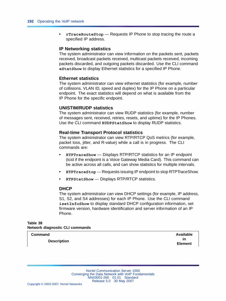
192 Operating the VoIP network
• rTraceRouteStop — Requests IP Phone to stop tracing the route aspecified IP address.
IP Networking statisticsThe system administrator can view information on the packets sent, packetsreceived, broadcast packets received, multicast packets received, incomingpackets discarded, and outgoing packets discarded. Use the CLI commandeStatShow to display Ethernet statistics for a specified IP Phone.
Ethernet statisticsThe system administrator can view ethernet statistics (for example, numberof collisions, VLAN ID, speed and duplex) for the IP Phone on a particularendpoint. The exact statistics will depend on what is available from theIP Phone for the specific endpoint.
UNISTIM/RUDP statisticsThe system administrator can view RUDP statistics (for example, numberof messages sent, received, retries, resets, and uptime) for the IP Phones.Use the CLI command RUDPStatShow to display RUDP statistics.
Real-time Transport Protocol statisticsThe system administrator can view RTP/RTCP QoS metrics (for example,packet loss, jitter, and R-value) while a call is in progress. The CLIcommands are:
• RTPTraceShow — Displays RTP/RTCP statistics for an IP endpoint(tcid if the endpoint is a Voice Gateway Media Card). This command canbe active across all calls, and can show statistics for multiple intervals.
• RTPTraceStop— Requests issuing IP endpoint to stop RTPTraceShow.
• RTPStatShow — Displays RTP/RTCP statistics.
DHCPThe system administrator can view DHCP settings (for example, IP address,S1, S2, and S4 addresses) for each IP Phone. Use the CLI commandisetInfoShow to display standard DHCP configuration information, setfirmware version, hardware identification and server information of an IPPhone.
Table 38Network diagnostic CLI commands
Command
Description
Availablein
Element
Nortel Communication Server 1000Converging the Data Network with VoIP Fundamentals
NN43001-260 01.01 StandardRelease 5.0 30 May 2007
Copyright © 2003-2007, Nortel Networks
.
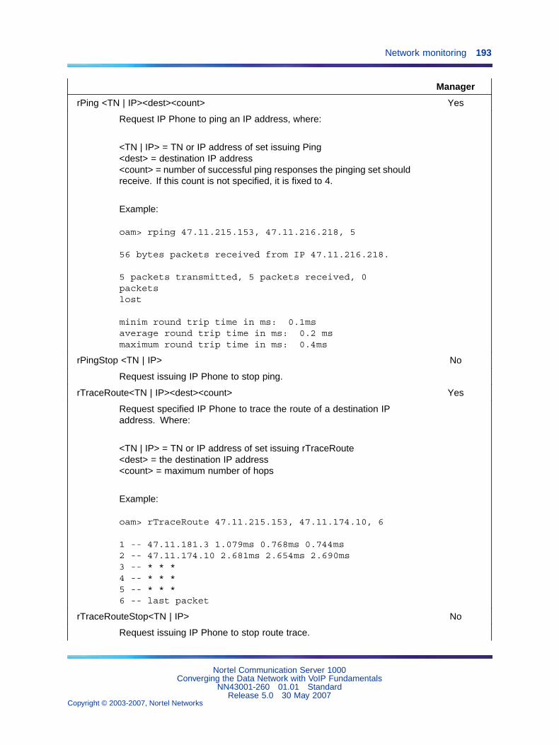
Network monitoring 193
Manager
rPing <TN | IP><dest><count> Yes
Request IP Phone to ping an IP address, where:
<TN | IP> = TN or IP address of set issuing Ping<dest> = destination IP address<count> = number of successful ping responses the pinging set shouldreceive. If this count is not specified, it is fixed to 4.
Example:
oam> rping 47.11.215.153, 47.11.216.218, 5
56 bytes packets received from IP 47.11.216.218.
5 packets transmitted, 5 packets received, 0packetslost
minim round trip time in ms: 0.1msaverage round trip time in ms: 0.2 msmaximum round trip time in ms: 0.4ms
rPingStop <TN | IP> No
Request issuing IP Phone to stop ping.
rTraceRoute<TN | IP><dest><count> Yes
Request specified IP Phone to trace the route of a destination IPaddress. Where:
<TN | IP> = TN or IP address of set issuing rTraceRoute<dest> = the destination IP address<count> = maximum number of hops
Example:
oam> rTraceRoute 47.11.215.153, 47.11.174.10, 6
1 -- 47.11.181.3 1.079ms 0.768ms 0.744ms2 -- 47.11.174.10 2.681ms 2.654ms 2.690ms3 -- * * *4 -- * * *5 -- * * *6 -- last packet
rTraceRouteStop<TN | IP> No
Request issuing IP Phone to stop route trace.
Nortel Communication Server 1000Converging the Data Network with VoIP Fundamentals
NN43001-260 01.01 StandardRelease 5.0 30 May 2007
Copyright © 2003-2007, Nortel Networks
.
194 Operating the VoIP network
Command
Description
Availablein
ElementManager
RUDPStatShow<TN | IP>[, <clear>] No
Display information received from an IP endpoint. Displayedinformation includes number of messages sent, number of messagesreceived, and number of retries. If specified, the statistics are clearedbefore display. Where:
<TN | IP> = TN or IP address of an IP Phone<clear> = Clear counts of messages sent, messages received, andnumber of retries, where:0 = Does not clear the statistics (default)1 = Clears the statistics and displays zero counts
Example - do not clear statistics:
oam> RUDPStatShow 47.11.215.153
Messages sent: 309Messages received: 321Number of retries: 10Uptime of current TPS registration: 2 hour 24minutes 35 seconds
Example - clear statistics:
oam> RUDPStatShow 47.11.215.153, 1
Messages sent: 0Messages received: 0Number of retries: 0Uptime of current TPS registration: 2 hour 24minutes 35 seconds
eStatShow<TN | IP>[, <clear>] No
Nortel Communication Server 1000Converging the Data Network with VoIP Fundamentals
NN43001-260 01.01 StandardRelease 5.0 30 May 2007
Copyright © 2003-2007, Nortel Networks
.
Network monitoring 195
Command
Description
Availablein
ElementManager
Display Ethernet information received from an IP endpoint. If specified,statistics are cleared before they are displayed. Displayed informationincludes:
• interface speed and duplex mode
• Auto negotiate protocol received/not received
• VLAN ID and priority
• packet collisions (peg count)
• CRC errors (peg count)
• framing errors (peg count)
Where:
<TN | IP> = TN or IP address of an IP endpoint.<clear> = Clears counts of packet collisions, CRC erros, and framingerrors, where:0 = Does not clear the statistics (default)1 = Clears the statistics and displays zero counts.
Example - do not clear statistics:
oam> eStatShow 47.11.215.153
100 base T full duplexAuto negotiate protocol receivedVLAN ID: 88Priority: 1Packet collisions: 100CRC errors: 30Framing Errors:1
Example - clear statistics:
oam> eStatShow 47.11.215.153, 1
100 base T full duplexAuto negotiate protocol receivedVLAN ID: 88Priority: 1
Nortel Communication Server 1000Converging the Data Network with VoIP Fundamentals
NN43001-260 01.01 StandardRelease 5.0 30 May 2007
Copyright © 2003-2007, Nortel Networks
.
196 Operating the VoIP network
Command
Description
Availablein
ElementManager
Packet collisions: 0CRC errors: 0Framing Errors: 0
isetInfoShow<TN | IP> Yes
Display standard DHCP configuration information, set firmwareversion, hardware identification and server information of an IP Phone.Where:
<TN | IP> = TN or IP address of the IP Phone.
Example:
oam> isetInfoShow 47.11.215.153
FW Version: 0602B50HWID: 18006038DD1ADB6600MAC: 006038DD1ADBVLAN ID: 124Priority: 6Set IP: 47.103.225.125Subnet Mask: 255.255.255.0Set Gateway: 47.103.225.1LTPS IP: 47.103.247.224Node IP: 47.103.247.224Node ID: 4420S1 Node IP: 47.103.247.229Port: 4100Action: 1S2 Node IP: 47.103.247.229Port: 4100Action: 1S5 Node IP: 47.103.247.229Port: 4100XAS: Net6
RTPStatShow<TN | IP> Yes
Nortel Communication Server 1000Converging the Data Network with VoIP Fundamentals
NN43001-260 01.01 StandardRelease 5.0 30 May 2007
Copyright © 2003-2007, Nortel Networks
.
Network monitoring 197
Command
Description
Availablein
ElementManager
Display QoS polling information. Where:
<TN | IP> = TN or IP address of the IP Phone.
Example:
Note: The output lines in this example are truncated to fit in theavailable space; each line of output is actually prefixed by the following:RTPStatShow Report (RTCP-XR) from Set (164.164.8.20)
oam> RTPStatShow 164.164.8.20
Far End IP address: 164.164.8.21Far End Port: 5200Local Packet Sent: 2978Local Packet Received: 2535Local Packet Received out of order: 0Local Pkt Loss: 14%Local Average Jitter: 0msLocal Latency: 9msLocal Listening R: 63Vocoder Type: 0Local Avg Net Loss Rate: 14.79%Local Avg Discard Rate: 0.00%Local Avg Burst Density: 17.11%Local Avg Burst Length: 2070msLocal Gap Density: 10.34%Local Gap Length: 1080msLocal Avg End System Delay: 15msLocal Avg Noise Level: 0dBmLocal Avg Signal Power: 0dBmLocal Round Trip Time Avg: 19msLocal Round Trip Time Avg High: 19msRemote Listening R: 0Remote Avg Net Loss Rate: 0%Remote Avg Discard Rate: 0%Remote Avg Burst Density: 0%Remote Avg Burst Length: 0msRemote Gap Density: 0%Remote Gap Length: 0msRemote Avg End System Delay: 0msRemote Avg Noise Level: 0dBmRemote Avg Signal Power: 0dBm
Nortel Communication Server 1000Converging the Data Network with VoIP Fundamentals
NN43001-260 01.01 StandardRelease 5.0 30 May 2007
Copyright © 2003-2007, Nortel Networks
.
198 Operating the VoIP network
Command
Description
Availablein
ElementManager
Remote Round Trip Time Avg: 0msRemote Round Trip Time Avg High: 0msRemote Packet Loss: 0%Remote Average Jitter: 0msRemote Latency: 0ms
RTPTraceShow<TN | IP>[, <polling period>] No
Display RTP/RTCP statistics for an IP endpoint. This command canbe active across all calls. Where:
• <TN IP> = TN or IP address of the endpoint (tcid if the endpoint isa Voice Gateway Media Card)
• <polling period> = Number of polling periods to be displayed. Ifnot specified, default is 10 polling periods.
Example:
Note: The output lines in this example are truncated to fit in theavailable space; each line of output is actually prefixed by the following:RTPTraceShow Report from Set (164.164.8.20)
oam> RTPTraceShow 164.164.8.20
Far End IP address: 164.164.8.21Far End Port: 5200Far End IP address: 164.164.8.21Far End Port: 5200Local Packet Sent: 2978Local Packet Received: 2535Local Packet Received out of order: 0Local Pkt Loss: 14%Local Average Jitter: 0msLocal Latency: 9msLocal Listening R: 63Vocoder Type: 0Local Avg Net Loss Rate: 14.79%Local Avg Discard Rate: 0.00%Local Avg Burst Density: 17.11%Local Avg Burst Length: 2070msLocal Gap Density: 10.34%
Nortel Communication Server 1000Converging the Data Network with VoIP Fundamentals
NN43001-260 01.01 StandardRelease 5.0 30 May 2007
Copyright © 2003-2007, Nortel Networks
.
Network monitoring 199
Command
Description
Availablein
ElementManager
Local Gap Length: 1080msLocal Avg End System Delay: 15msLocal Avg Noise Level: 0dBmLocal Avg Signal Power: 0dBmLocal Round Trip Time Avg: 19msLocal Round Trip Time Avg High: 19msRemote Listening R: 0Remote Avg Net Loss Rate: 0%Remote Avg Discard Rate: 0%Remote Avg Burst Density: 0%Remote Avg Burst Length: 0msRemote Gap Density: 0%Remote Gap Length: 0msRemote Avg End System Delay: 0msRemote Avg Noise Level: 0dBmRemote Avg Signal Power: 0dBmRemote Round Trip Time Avg: 0msRemote Round Trip Time Avg High: 0msRemote Packet Loss: 0%Remote Average Jitter: 0ms Remote Latency: 0ms
RTPTraceStop No
Request issuing IP endpoint to stop RTPTraceShow.
For information on network diagnostic utilities, refer to IP PhonesFundamentals (NN43001-368) and Signaling Server Installation andCommissioning (NN43001-312).
Proactive Voice Quality ManagementFor Communication Server 1000 Release 4.5 (and later), Proactive VoiceQuality Management (PVQM) assists system administrators to:
• make informed decisions for capacity planning, and QoS networkengineering
• monitor the performance of their system
• diagnose, isolate, and correct networking problems that causedeterioration in voice quality
PVQM is supported by CS 1000 and Meridian 1 systems equipped withVoice Gateway Media Cards running IP Line 4.0 (or later). PVQM includesthe following:
• monitoring of voice quality metrics (for example, latency, jitter, packetloss, and R-Value) for IP Phones and gateway endpoints
Nortel Communication Server 1000Converging the Data Network with VoIP Fundamentals
NN43001-260 01.01 StandardRelease 5.0 30 May 2007
Copyright © 2003-2007, Nortel Networks
.
200 Operating the VoIP network
Note: Monitoring of R-Value available on Phase II IP Phonesonly. To enable monitoring of the R-Value audio quality metric,the Proactive Voice Quality Management (PVQM) package 401 isrequired.
• two levels of voice quality alarms (for example, Warning andUnacceptable). Alarm thresholds, configured in LD 117, are used toclassify system performance as good, poor, and unacceptable.
Note: Available on Phase II IP Phones only.
• SNMP alarm generation when voice quality metric thresholds areviolated on a per-call or bandwidth-zone basis
• controlling the number of voice quality-related SNMP alarms (on azone-by-zone basis) by configuring zone alarm notification in LD 117.Alarm control assists in isolating voice quality problems and reducingnetwork traffic.
• recording of voice quality metric threshold violations, accessible in IPPhone Zone Traffic Report 16 (LD 2) and SNMP MIB
Note: IP Phone Zone Traffic Report 16 (TFS016) includes pegcounts for both alarm levels (that is, Warning and Unacceptable)when recording voice quality metric threshold violations for latency,jitter, and packet loss. R-Value is limited to one peg count (that is,Unacceptable).
• R-Value information is available in Operational Measurement (OM)reports. OM reports contain hourly summations of voice quality metricsand endpoint registration activity.
• network diagnostic utilities to identify, isolate, and report networkproblems affecting voice quality. The diagnostic utilities are available byusing the Command Line Interface (CLI) or IP Phones with Phase IIsoftware. The utilities include Traceroute, Ping, Ethernet statistics, IPNetwork statistics, UNIStim/RUDP statistics, RTCP statistics, and DHCPdata. See "Network Diagnostic Utilities" (page 191).
How voice quality monitoring worksThe PVQM feature monitors voice quality by measuring the following:
• Latency - length of time for information to travel through the network,in seconds
• Jitter - variability in latency, in seconds
• Packet Loss - number of packets lost during transmission, in percentage
• R-Value - measurement of listening R-Value using ITU E-Model.R-Value maps to Mean Opinion Score (MOS).
Nortel Communication Server 1000Converging the Data Network with VoIP Fundamentals
NN43001-260 01.01 StandardRelease 5.0 30 May 2007
Copyright © 2003-2007, Nortel Networks
.
Network monitoring 201
The sampled metrics are compared to user-configured thresholds in order todetermine system performance. When sampled metrics exceed configuredthresholds, statistics are generated on the system.
Note: For details on configuring metric thresholds, refer to "Configurevoice quality metric thresholds" (page 205).
Statistics for each metric are collected on the Signaling Server or VoiceGateway Media Card to create a traffic report. The traffic report classifiesmetric threshold violation peg counts as Warning or Unacceptable.
Each summarized traffic report is added to the IP Phone Zone Traffic Report16 (TFS016), which in turn summarizes voice quality over the reportingperiod on a zone-by-zone basis. IP Phone Zone Traffic Report 16 (TFS016)provides the system administrator with an overall view of voice quality on thesystem. For information on IP Phone Zone Traffic Report 16 (TFS016), referto Traffic Measurement: Formats and Output Reference (NN43001-750).
An SNMP alarm is generated when a voice quality metric threshold exceedsWarning or Unacceptable status. For details on controlling the numberof SNMP alarms generated, refer to "Configure and print zone alarmnotification levels" (page 205).
Phase I IP Phones voice quality monitoringFigure 42 "Phase I IP Phones voice quality monitoring flow diagram" (page202) shows voice quality monitoring for Phase I IP Phones within the VoIPsystem.
Nortel Communication Server 1000Converging the Data Network with VoIP Fundamentals
NN43001-260 01.01 StandardRelease 5.0 30 May 2007
Copyright © 2003-2007, Nortel Networks
.
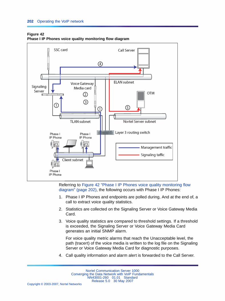
202 Operating the VoIP network
Figure 42Phase I IP Phones voice quality monitoring flow diagram
Referring to Figure 42 "Phase I IP Phones voice quality monitoring flowdiagram" (page 202), the following occurs with Phase I IP Phones:
1. Phase I IP Phones and endpoints are polled during, And at the end of, acall to extract voice quality statistics.
2. Statistics are collected on the Signaling Server or Voice Gateway MediaCard.
3. Voice quality statistics are compared to threshold settings. If a thresholdis exceeded, the Signaling Server or Voice Gateway Media Cardgenerates an initial SNMP alarm.
For voice quality metric alarms that reach the Unacceptable level, thepath (tracert) of the voice media is written to the log file on the SignalingServer or Voice Gateway Media Card for diagnostic purposes.
4. Call quality information and alarm alert is forwarded to the Call Server.
Nortel Communication Server 1000Converging the Data Network with VoIP Fundamentals
NN43001-260 01.01 StandardRelease 5.0 30 May 2007
Copyright © 2003-2007, Nortel Networks
.
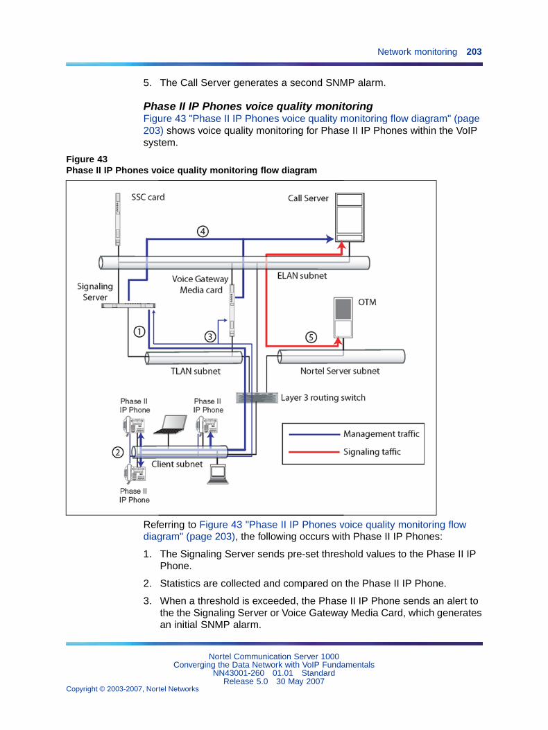
Network monitoring 203
5. The Call Server generates a second SNMP alarm.
Phase II IP Phones voice quality monitoringFigure 43 "Phase II IP Phones voice quality monitoring flow diagram" (page203) shows voice quality monitoring for Phase II IP Phones within the VoIPsystem.
Figure 43Phase II IP Phones voice quality monitoring flow diagram
Referring to Figure 43 "Phase II IP Phones voice quality monitoring flowdiagram" (page 203), the following occurs with Phase II IP Phones:
1. The Signaling Server sends pre-set threshold values to the Phase II IPPhone.
2. Statistics are collected and compared on the Phase II IP Phone.
3. When a threshold is exceeded, the Phase II IP Phone sends an alert tothe the Signaling Server or Voice Gateway Media Card, which generatesan initial SNMP alarm.
Nortel Communication Server 1000Converging the Data Network with VoIP Fundamentals
NN43001-260 01.01 StandardRelease 5.0 30 May 2007
Copyright © 2003-2007, Nortel Networks
.
204 Operating the VoIP network
For voice quality metric alarms that reach the Unacceptable level, thepath (tracert) of the voice media is written to the log file on the SignalingServer or Voice Gateway Media Card for diagnostic purposes.
4. Call quality information and alarm alert is forwarded to the Call Server.
5. The Call Server generates a second SNMP alarm.
Voice quality alarmsTable 39 "Call Server alarms - Call-by-call" (page 204) identifies metrics,threshold levels, alarming severity, and QoS alarms for the followingcategories:
• Call Server alarms on a call-by-call basis
• Call Server alarms aggregated by zone
• Signaling Server (LTPS) alarms
Table 39Call Server alarms - Call-by-call
MetricThreshold
level Severity Alarms
Call Server alarms - Call-by-call
Latency, Jitter, Packet Loss, R-Value Warning Info QOS0001 - QOS0005(excluding QOS0004)
Latency, Jitter, Packet Loss, R-Value Unacceptable Minor QOS0007 - QOS0010
Call Server alarms - Aggregated by zone
Latency, Jitter, Packet Loss, R-Value Warning Minor QOS0012 - QOS0015
Latency, Jitter, Packet Loss, R-Value Unacceptable Critical QOS0017 - QOS0020
Signaling Server (LTPS) alarms
Latency, Jitter, Packet Loss, R-Value Warning Warning QOS0022, QOS0024,QOS0026, QOS0028
Latency, Jitter, Packet Loss, R-Value Unacceptable Minor QOS0030, QOS0032,QOS0034, QOS0036
Latency, Jitter, Packet Loss, R-Value Clear Clear QOS0023, QOS0027,QOS0029, QOS0031,QOS0033, QOS0035,QOS0037
For information on QoS alarms, refer to Software Input Output Reference -System Messages (NN43001-712).
Nortel Communication Server 1000Converging the Data Network with VoIP Fundamentals
NN43001-260 01.01 StandardRelease 5.0 30 May 2007
Copyright © 2003-2007, Nortel Networks
.
Network monitoring 205
Configure voice quality metric thresholdsThe system administrator can configure and print voice quality metricthresholds on a per-call or zone basis. Use the following commands inLD 117:
• CHG CQWTH — Change voice quality Warning thresholds on a per callbasis.
• CHG CQUTH — Change voice quality Unacceptable thresholds on aper call basis.
• CHG ZQWTH — Change voice quality Warning thresholds on a zonebasis.
• CHG ZQUTH — Change voice quality Unacceptable thresholds on azone basis.
• PRT QSTHS — Display all voice quality thresholds.
• PRT AQOS — Display QoS records for zones.
• PRT ZQOS — Display QoS records for zones.
For detailed information on these commands, refer to Software Input/Output:Maintenance (NN43001-711).
Configure voice quality sampling (polling)Use the CHG SQOS command in LD 117 to configure the sampling (polling)period, zone-alarm-rate collection window, and the minimum number ofsamples to collect during the window.
For detailed information on these commands, refer to Software Input/Output:Maintenance (NN43001-711).
Configure and print zone alarm notification levelsSystems that process a large number of calls potentially generate asignificant number of SNMP alarms. Controlling the number of alarmsby configuring zone alarm notification levels helps isolate voice qualityproblems and reduce network traffic.
Voice quality threshold alarms are examined for their severity relative to thealarm notification level settings. If the voice quality threshold alarm severityexceeds the configured notification level, it generates an SNMP alarm;otherwise, the alarm is suppressed.
Nortel Communication Server 1000Converging the Data Network with VoIP Fundamentals
NN43001-260 01.01 StandardRelease 5.0 30 May 2007
Copyright © 2003-2007, Nortel Networks
.

206 Operating the VoIP network
Voice quality threshold alarm notification levels can be set on a zone-by-zonebasis so that some bandwidth zones can be monitored for all alarmsand other zones will report only serious voice quality problems. Alarmnotification levels are defined in Table 40 "Voice quality threshold alarmnotification levels" (page 206).
Table 40Voice quality threshold alarm notification levels
Level Description Alarms
0 All voice quality alarms are suppressed None
1 Allow zone-based Unacceptable alarms QOS0017, QOS0018,QOS0019, QOS0020
2 Allow all of the above PLUS zone-basedWarning alarms
All of the above PLUS,QOS0012,QOS0013, QOS0014, QOS0015
3 Allow all of the above PLUS per-callUnacceptable alarms
All of the above PLUS,QOS0007,QOS0008, QOS0009,QOS0010,QOS0032, QOS0033,QOS0036,QOS0037
4 Allow all of the above PLUS per-call Warningalarms
All of the above PLUS,QOS0001,QOS0002, QOS0003,QOS0005,QOS0018, QOS0019,QOS0022,QOS0023, QOS0024,QOS0025,QOS0026, QOS0027
The system administrator controls the number of alarms generated bythe system using the CHG ZQNL alarm notification level configurationcommands. The system administrator can print alarm notification levelsusing the PRT ZQNL command. Both commands are in LD 117.
For detailed information on these commands, refer to Software Input/Output:Maintenance (NN43001-711).
Heterogeneous environmentsIn an environment with a mixture of Nortel equipment and third-partyequipment, voice-quality monitoring, detection, and alarming is performedonly on IP endpoints that have voice quality monitoring capabilities.
Nortel Communication Server 1000Converging the Data Network with VoIP Fundamentals
NN43001-260 01.01 StandardRelease 5.0 30 May 2007
Copyright © 2003-2007, Nortel Networks
.
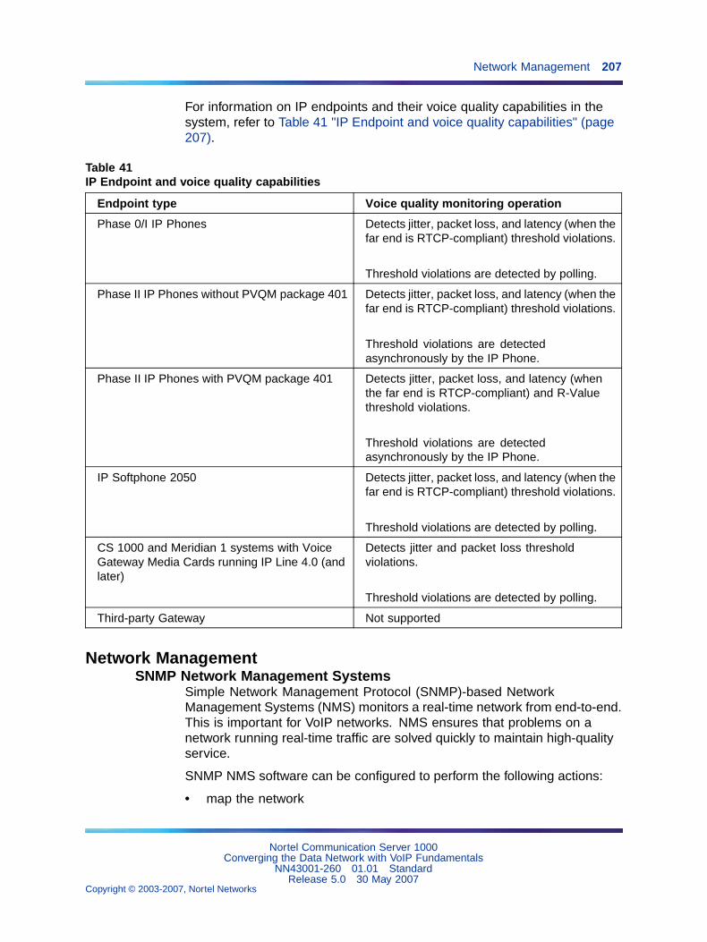
Network Management 207
For information on IP endpoints and their voice quality capabilities in thesystem, refer to Table 41 "IP Endpoint and voice quality capabilities" (page207).
Table 41IP Endpoint and voice quality capabilities
Endpoint type Voice quality monitoring operation
Phase 0/I IP Phones Detects jitter, packet loss, and latency (when thefar end is RTCP-compliant) threshold violations.
Threshold violations are detected by polling.
Phase II IP Phones without PVQM package 401 Detects jitter, packet loss, and latency (when thefar end is RTCP-compliant) threshold violations.
Threshold violations are detectedasynchronously by the IP Phone.
Phase II IP Phones with PVQM package 401 Detects jitter, packet loss, and latency (whenthe far end is RTCP-compliant) and R-Valuethreshold violations.
Threshold violations are detectedasynchronously by the IP Phone.
IP Softphone 2050 Detects jitter, packet loss, and latency (when thefar end is RTCP-compliant) threshold violations.
Threshold violations are detected by polling.
CS 1000 and Meridian 1 systems with VoiceGateway Media Cards running IP Line 4.0 (andlater)
Detects jitter and packet loss thresholdviolations.
Threshold violations are detected by polling.
Third-party Gateway Not supported
Network ManagementSNMP Network Management Systems
Simple Network Management Protocol (SNMP)-based NetworkManagement Systems (NMS) monitors a real-time network from end-to-end.This is important for VoIP networks. NMS ensures that problems on anetwork running real-time traffic are solved quickly to maintain high-qualityservice.
SNMP NMS software can be configured to perform the following actions:
• map the network
Nortel Communication Server 1000Converging the Data Network with VoIP Fundamentals
NN43001-260 01.01 StandardRelease 5.0 30 May 2007
Copyright © 2003-2007, Nortel Networks
.
208 Operating the VoIP network
• monitor network operation through polling of network devices
• centralize alarm management through SNMP traps
• notify network administrators of problems
The CS 1000 system can be integrated into an NMS to provide a completeview of the converged voice and data network. Problems can be isolatedmuch more quickly when looking at the entire network.
SNMP Agent support is provided in TM. This allows alarms sent fromdevices to be forwarded to the NMS.
Nortel also provides a complete line of Enterprise Network managementsoftware with the Optivity Enterprise Network Management Solutionsproduct line. An SNMP interface is available in the traffic reporting systemso that TM, or any third-party system, can have a standards-based interfaceinto the system traffic reports. Refer to Simple Network ManagementProtocol: Description and Maintenance (NN43001-719).
TM and Network Management SystemTM can be combined with Optivity Network Management System (OptivityNMS) Release 9.01, and later. This provides an integrated data, voice,and video network, as part of a Unified Networking system. The result isintegrated LAN, WAN, and voice network management.
Optivity NMS is an enterprise-level network management solution, providingfault, performance, configuration, and security management for Nortelinternetworking devices. Optivity NMS enables network administrators tomonitor and manage the network through a single view, and access anyOptivity NMS server in the network from one client installation. It providessystem-level management instead of managing one device at a time.Optivity NMS provides graphical views from physical connections betweenthe LANs and WANs to the logical connections of a VLAN.
TM server activity can be monitored through Optivity NMS.
TM Alarm Manager receives Simple Network Management Protocol (SNMP)traps from managed elements. Through Alarm Notification, TM sendsfiltered traps to Optivity NMS.
Policy ManagementPolicy Management simplifies network QoS configuration by managingnetwork QoS policies from a central location.
Nortel Communication Server 1000Converging the Data Network with VoIP Fundamentals
NN43001-260 01.01 StandardRelease 5.0 30 May 2007
Copyright © 2003-2007, Nortel Networks
.
Network Management 209
Details such as Layer 2, Layer 3, Layer 4, and trust configurations can beimplemented for the entire network from a central location. A variety ofpolicy managers are usually available from the network equipment vendor.
The Common Open Policy Services (COPS) protocol is used to transmitstandard policies to the network devices.
For more details on Nortel Optivity Policy Services, contact your Nortelrepresentative.
CS 1000 network inventory and configurationRecord the current CS 1000 design and log all additions, moves, andchanges that occur in the CS 1000 network. The following information mustbe recorded:
• CS 1000 site information
— location
— dialing plan
— IP addressing
• Provisioning of CS 1000 nodes
— number of cards and ports
• CS 1000 node and card parameters
— fallback threshold level
— CODEC image
— voice and fax payload
— voice and fax playout delay
— audio gain, echo canceller tail delay size, Silence Suppressionthreshold
— software version
Nortel Communication Server 1000Converging the Data Network with VoIP Fundamentals
NN43001-260 01.01 StandardRelease 5.0 30 May 2007
Copyright © 2003-2007, Nortel Networks
.

210 Operating the VoIP network
Nortel Communication Server 1000Converging the Data Network with VoIP Fundamentals
NN43001-260 01.01 StandardRelease 5.0 30 May 2007
Copyright © 2003-2007, Nortel Networks
.
211
Appendix ASubnet mask conversion
Subnet mask conversion from CIDR to dotted decimal format
Subnet masks are expressed in Classless InterDomain Routing (CIDR)format, appended to the IP address, such as 10.1.1.1/20. The subnet maskmust be converted from CIDR format to dotted decimal format in order toconfigure IP addresses.
The CIDR format expresses the subnet mask as the number of bits countingfrom the most significant bit of the first IP address field. A complete IPaddress consists of 32 bits. Therefore, a typical CIDR format subnet maskis in the range from /9 to /30. Each decimal number field in the dotteddecimal format has a value from 0 to 255, where decimal 255 representsbinary 1111 1111.
Follow the steps in Procedure 9 "Converting a subnet mask from CIDRformat to dotted decimal format" (page 211) to convert a subnet mask fromCIDR format to dotted decimal format.
Procedure 9Converting a subnet mask from CIDR formatto dotted decimal format
Step Action
1 Divide the CIDR format value by 8.
The result is a quotient (a zero or a positive number) and a remainderbetween 0 and 7.
2 The quotient designates the number of dotted decimal fieldscontaining 255.
In the example above, the subnet mask in CIDR format is "/20".Twenty divided by eight equals a quotient of two, with a remainderof four. Therefore, the first two fields of the subnet mask in dotteddecimal format are 255.255.
Nortel Communication Server 1000Converging the Data Network with VoIP Fundamentals
NN43001-260 01.01 StandardRelease 5.0 30 May 2007
Copyright © 2003-2007, Nortel Networks
.
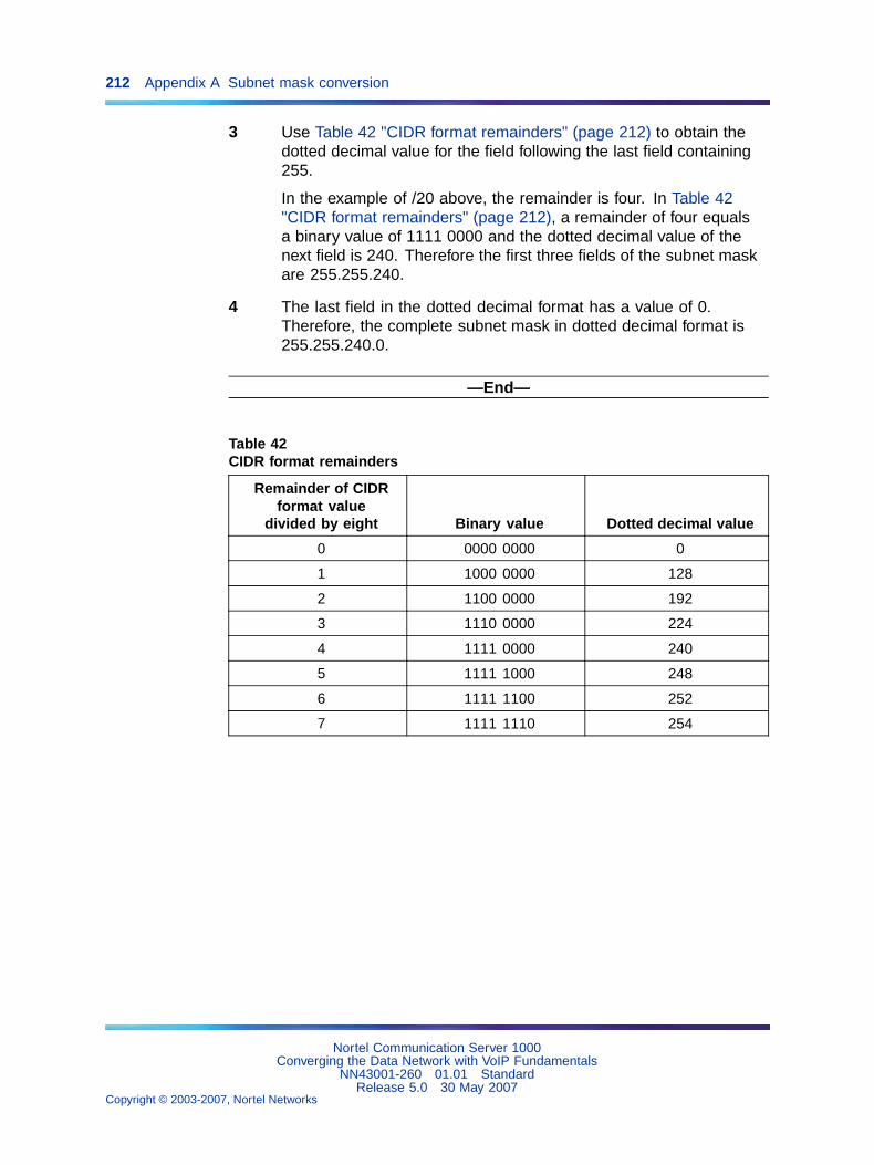
212 Appendix A Subnet mask conversion
3 Use Table 42 "CIDR format remainders" (page 212) to obtain thedotted decimal value for the field following the last field containing255.
In the example of /20 above, the remainder is four. In Table 42"CIDR format remainders" (page 212), a remainder of four equalsa binary value of 1111 0000 and the dotted decimal value of thenext field is 240. Therefore the first three fields of the subnet maskare 255.255.240.
4 The last field in the dotted decimal format has a value of 0.Therefore, the complete subnet mask in dotted decimal format is255.255.240.0.
—End—
Table 42CIDR format remainders
Remainder of CIDRformat value
divided by eight Binary value Dotted decimal value
0 0000 0000 0
1 1000 0000 128
2 1100 0000 192
3 1110 0000 224
4 1111 0000 240
5 1111 1000 248
6 1111 1100 252
7 1111 1110 254
Nortel Communication Server 1000Converging the Data Network with VoIP Fundamentals
NN43001-260 01.01 StandardRelease 5.0 30 May 2007
Copyright © 2003-2007, Nortel Networks
.
213
Appendix BPort number tables
ContentsThis section contains information on the following topics:
"Introduction" (page 213)
"Call Server port numbers" (page 214)
"Signaling Server port numbers" (page 216)
"IP Line port numbers" (page 218)
"IP Trunk port numbers" (page 219)
"Internet Telephony Gateway (ITG) port numbers" (page 220)
"TM port numbers" (page 221)
"IP Phone port numbers" (page 222)
"Remote Office port numbers" (page 222)
"CallPilot port numbers" (page 223)
"Symposium port numbers" (page 226)
"TLAN subnet stateless packet filtering" (page 226)
"TLAN subnet stateful packet filtering" (page 227)
"ELAN subnet packet filtering" (page 229)
IntroductionThis appendix contains port number tables for all Meridian 1, CS 1000S,and CS 1000M VoIP products.
All ports specified in the following tables are "Listen" ports. That is, thesetables specify the destination IP address and destination port number. Thetables do not specify the source IP address or port.
The Task column specifies the software task listening on the specified port.
Nortel Communication Server 1000Converging the Data Network with VoIP Fundamentals
NN43001-260 01.01 StandardRelease 5.0 30 May 2007
Copyright © 2003-2007, Nortel Networks
.
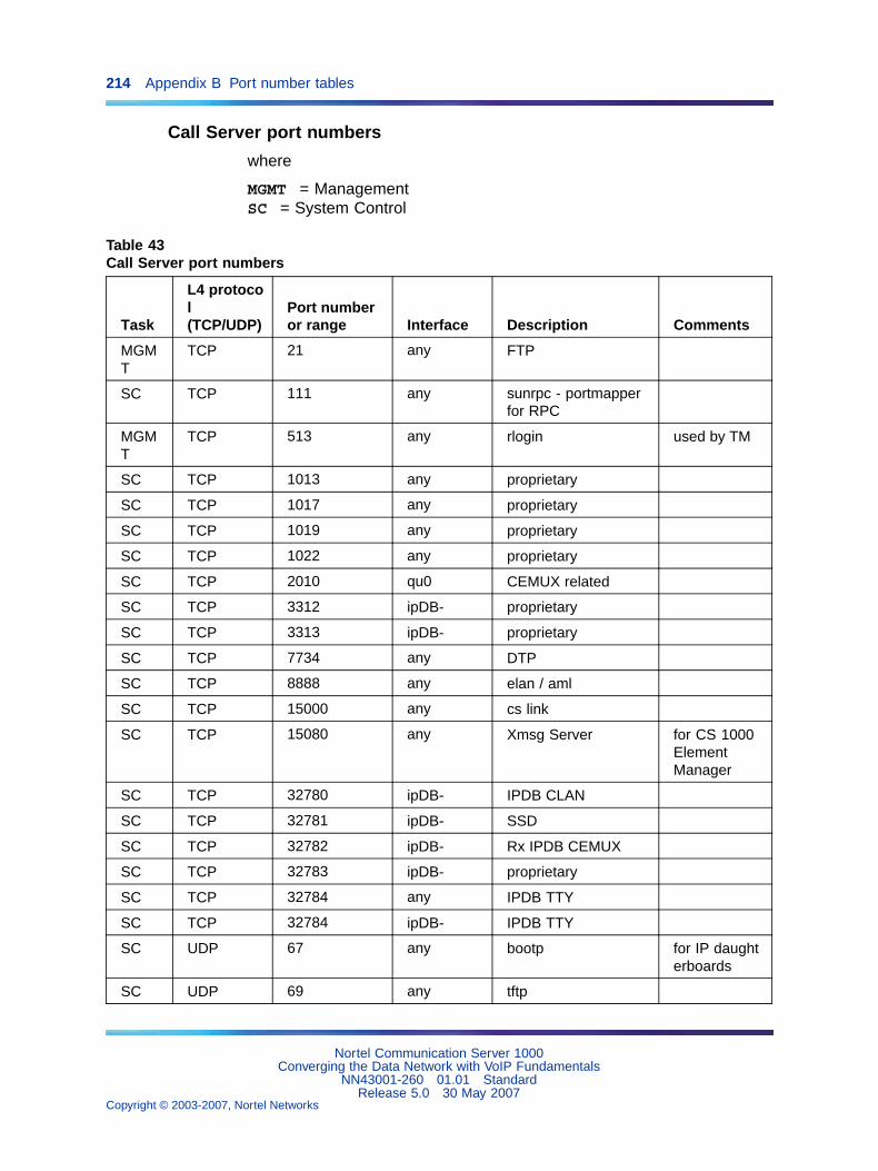
214 Appendix B Port number tables
Call Server port numbers
where
MGMT = ManagementSC = System Control
Table 43Call Server port numbers
Task
L4 protocol(TCP/UDP)
Port numberor range Interface Description Comments
MGMT
TCP 21 any FTP
SC TCP 111 any sunrpc - portmapperfor RPC
MGMT
TCP 513 any rlogin used by TM
SC TCP 1013 any proprietary
SC TCP 1017 any proprietary
SC TCP 1019 any proprietary
SC TCP 1022 any proprietary
SC TCP 2010 qu0 CEMUX related
SC TCP 3312 ipDB- proprietary
SC TCP 3313 ipDB- proprietary
SC TCP 7734 any DTP
SC TCP 8888 any elan / aml
SC TCP 15000 any cs link
SC TCP 15080 any Xmsg Server for CS 1000ElementManager
SC TCP 32780 ipDB- IPDB CLAN
SC TCP 32781 ipDB- SSD
SC TCP 32782 ipDB- Rx IPDB CEMUX
SC TCP 32783 ipDB- proprietary
SC TCP 32784 any IPDB TTY
SC TCP 32784 ipDB- IPDB TTY
SC UDP 67 any bootp for IP daughterboards
SC UDP 69 any tftp
Nortel Communication Server 1000Converging the Data Network with VoIP Fundamentals
NN43001-260 01.01 StandardRelease 5.0 30 May 2007
Copyright © 2003-2007, Nortel Networks
.
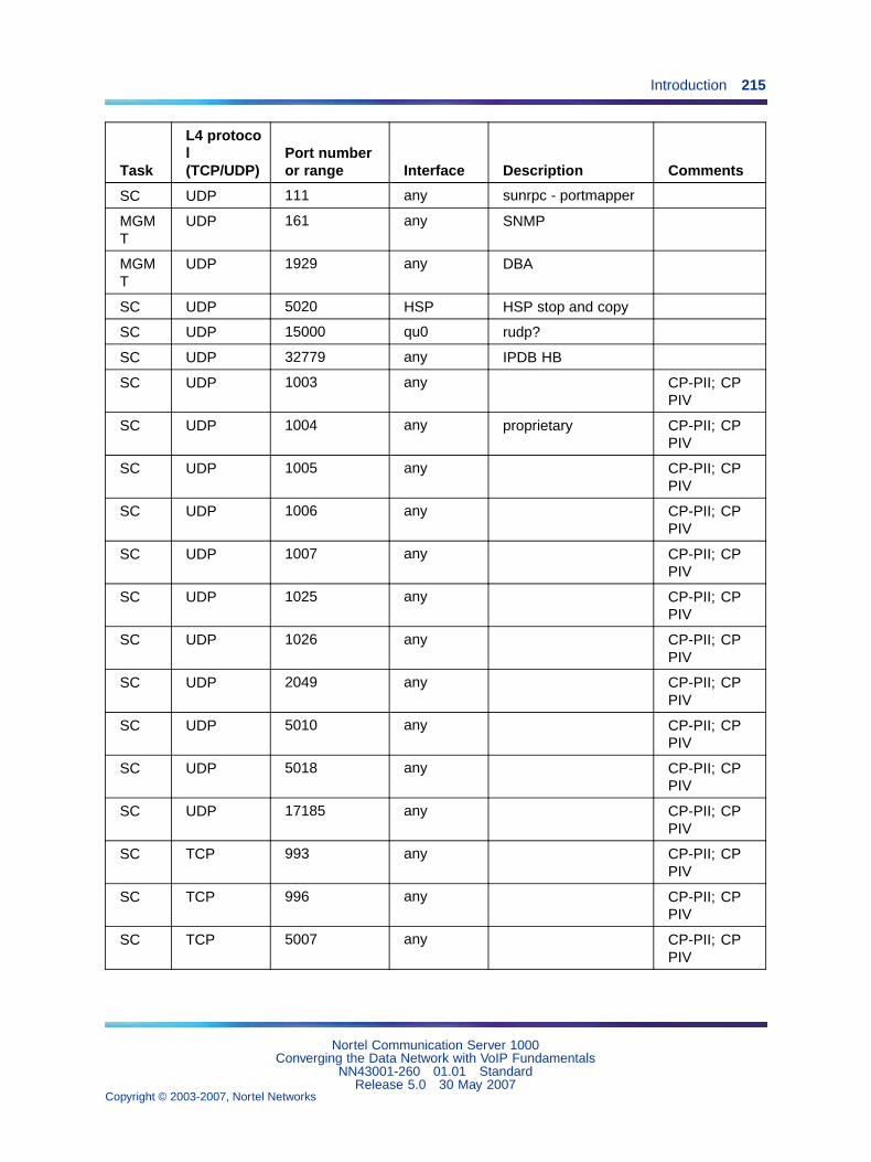
Introduction 215
Task
L4 protocol(TCP/UDP)
Port numberor range Interface Description Comments
SC UDP 111 any sunrpc - portmapper
MGMT
UDP 161 any SNMP
MGMT
UDP 1929 any DBA
SC UDP 5020 HSP HSP stop and copy
SC UDP 15000 qu0 rudp?
SC UDP 32779 any IPDB HB
SC UDP 1003 any CP-PII; CPPIV
SC UDP 1004 any proprietary CP-PII; CPPIV
SC UDP 1005 any CP-PII; CPPIV
SC UDP 1006 any CP-PII; CPPIV
SC UDP 1007 any CP-PII; CPPIV
SC UDP 1025 any CP-PII; CPPIV
SC UDP 1026 any CP-PII; CPPIV
SC UDP 2049 any CP-PII; CPPIV
SC UDP 5010 any CP-PII; CPPIV
SC UDP 5018 any CP-PII; CPPIV
SC UDP 17185 any CP-PII; CPPIV
SC TCP 993 any CP-PII; CPPIV
SC TCP 996 any CP-PII; CPPIV
SC TCP 5007 any CP-PII; CPPIV
Nortel Communication Server 1000Converging the Data Network with VoIP Fundamentals
NN43001-260 01.01 StandardRelease 5.0 30 May 2007
Copyright © 2003-2007, Nortel Networks
.
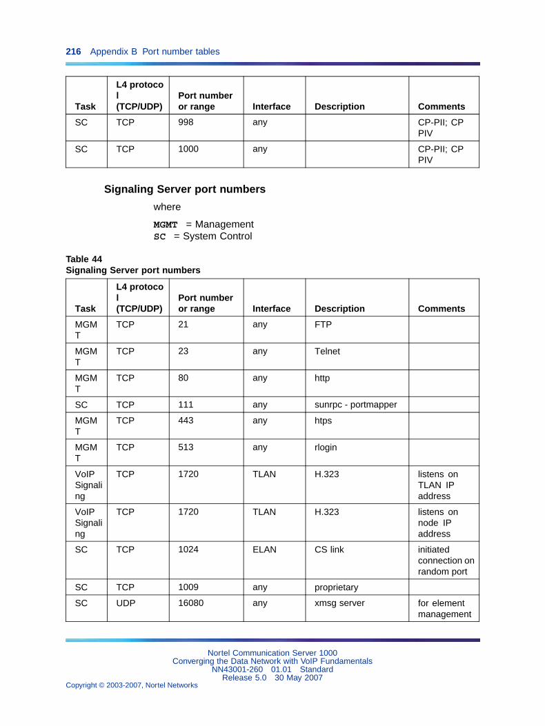
216 Appendix B Port number tables
Task
L4 protocol(TCP/UDP)
Port numberor range Interface Description Comments
SC TCP 998 any CP-PII; CPPIV
SC TCP 1000 any CP-PII; CPPIV
Signaling Server port numbers
where
MGMT = ManagementSC = System Control
Table 44Signaling Server port numbers
Task
L4 protocol(TCP/UDP)
Port numberor range Interface Description Comments
MGMT
TCP 21 any FTP
MGMT
TCP 23 any Telnet
MGMT
TCP 80 any http
SC TCP 111 any sunrpc - portmapper
MGMT
TCP 443 any htps
MGMT
TCP 513 any rlogin
VoIPSignaling
TCP 1720 TLAN H.323 listens onTLAN IPaddress
VoIPSignaling
TCP 1720 TLAN H.323 listens onnode IPaddress
SC TCP 1024 ELAN CS link initiatedconnection onrandom port
SC TCP 1009 any proprietary
SC UDP 16080 any xmsg server for elementmanagement
Nortel Communication Server 1000Converging the Data Network with VoIP Fundamentals
NN43001-260 01.01 StandardRelease 5.0 30 May 2007
Copyright © 2003-2007, Nortel Networks
.
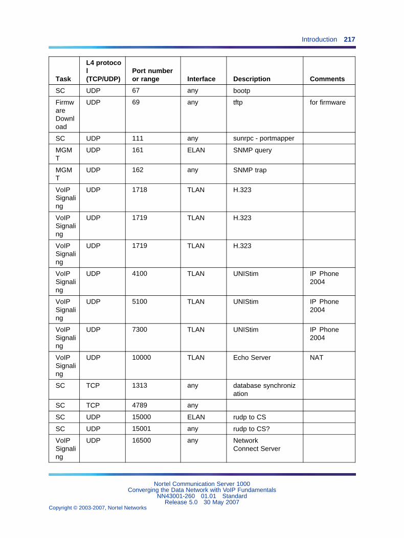
Introduction 217
Task
L4 protocol(TCP/UDP)
Port numberor range Interface Description Comments
SC UDP 67 any bootp
FirmwareDownload
UDP 69 any tftp for firmware
SC UDP 111 any sunrpc - portmapper
MGMT
UDP 161 ELAN SNMP query
MGMT
UDP 162 any SNMP trap
VoIPSignaling
UDP 1718 TLAN H.323
VoIPSignaling
UDP 1719 TLAN H.323
VoIPSignaling
UDP 1719 TLAN H.323
VoIPSignaling
UDP 4100 TLAN UNIStim IP Phone2004
VoIPSignaling
UDP 5100 TLAN UNIStim IP Phone2004
VoIPSignaling
UDP 7300 TLAN UNIStim IP Phone2004
VoIPSignaling
UDP 10000 TLAN Echo Server NAT
SC TCP 1313 any database synchronization
SC TCP 4789 any
SC UDP 15000 ELAN rudp to CS
SC UDP 15001 any rudp to CS?
VoIPSignaling
UDP 16500 any NetworkConnect Server
Nortel Communication Server 1000Converging the Data Network with VoIP Fundamentals
NN43001-260 01.01 StandardRelease 5.0 30 May 2007
Copyright © 2003-2007, Nortel Networks
.
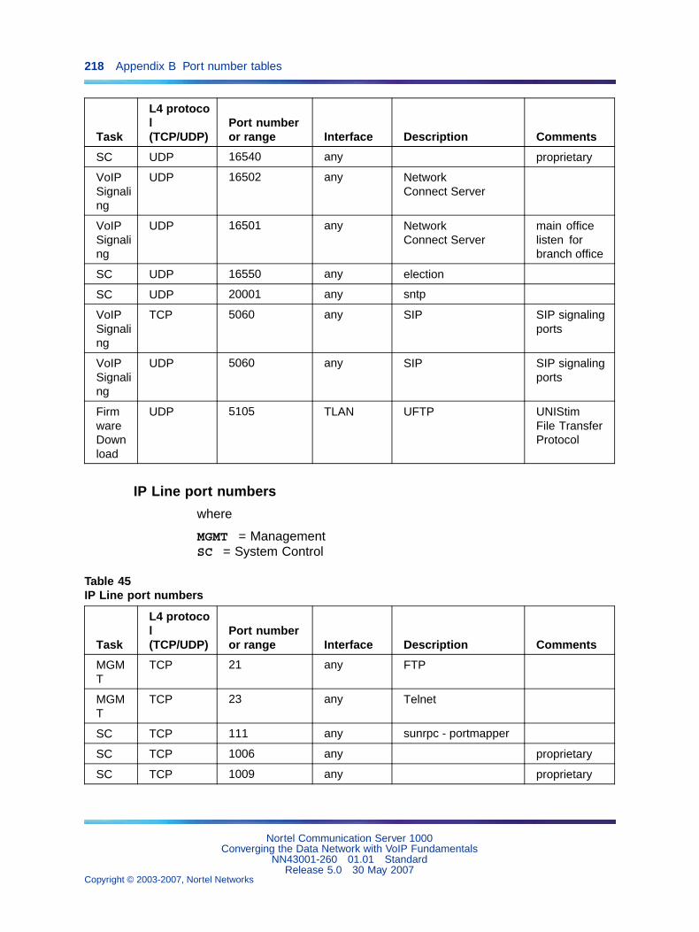
218 Appendix B Port number tables
Task
L4 protocol(TCP/UDP)
Port numberor range Interface Description Comments
SC UDP 16540 any proprietary
VoIPSignaling
UDP 16502 any NetworkConnect Server
VoIPSignaling
UDP 16501 any NetworkConnect Server
main officelisten forbranch office
SC UDP 16550 any election
SC UDP 20001 any sntp
VoIPSignaling
TCP 5060 any SIP SIP signalingports
VoIPSignaling
UDP 5060 any SIP SIP signalingports
FirmwareDownload
UDP 5105 TLAN UFTP UNIStimFile TransferProtocol
IP Line port numbers
where
MGMT = ManagementSC = System Control
Table 45IP Line port numbers
Task
L4 protocol(TCP/UDP)
Port numberor range Interface Description Comments
MGMT
TCP 21 any FTP
MGMT
TCP 23 any Telnet
SC TCP 111 any sunrpc - portmapper
SC TCP 1006 any proprietary
SC TCP 1009 any proprietary
Nortel Communication Server 1000Converging the Data Network with VoIP Fundamentals
NN43001-260 01.01 StandardRelease 5.0 30 May 2007
Copyright © 2003-2007, Nortel Networks
.
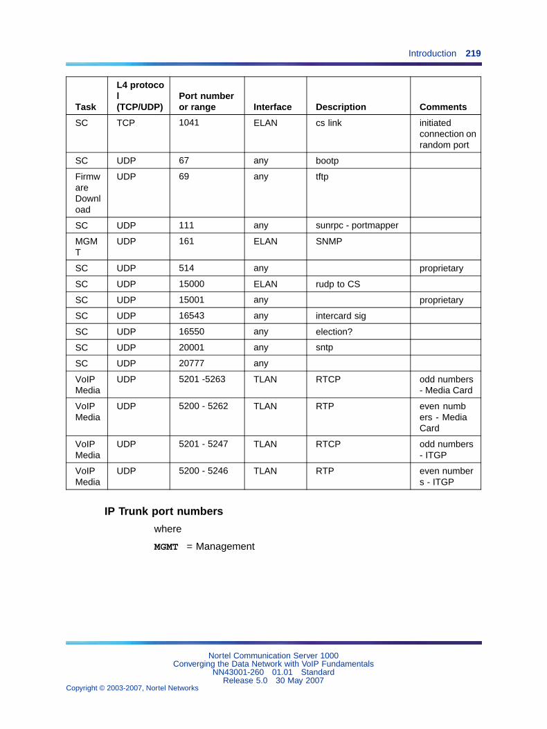
Introduction 219
Task
L4 protocol(TCP/UDP)
Port numberor range Interface Description Comments
SC TCP 1041 ELAN cs link initiatedconnection onrandom port
SC UDP 67 any bootp
FirmwareDownload
UDP 69 any tftp
SC UDP 111 any sunrpc - portmapper
MGMT
UDP 161 ELAN SNMP
SC UDP 514 any proprietary
SC UDP 15000 ELAN rudp to CS
SC UDP 15001 any proprietary
SC UDP 16543 any intercard sig
SC UDP 16550 any election?
SC UDP 20001 any sntp
SC UDP 20777 any
VoIPMedia
UDP 5201 -5263 TLAN RTCP odd numbers- Media Card
VoIPMedia
UDP 5200 - 5262 TLAN RTP even numbers - MediaCard
VoIPMedia
UDP 5201 - 5247 TLAN RTCP odd numbers- ITGP
VoIPMedia
UDP 5200 - 5246 TLAN RTP even numbers - ITGP
IP Trunk port numbers
where
MGMT = Management
Nortel Communication Server 1000Converging the Data Network with VoIP Fundamentals
NN43001-260 01.01 StandardRelease 5.0 30 May 2007
Copyright © 2003-2007, Nortel Networks
.
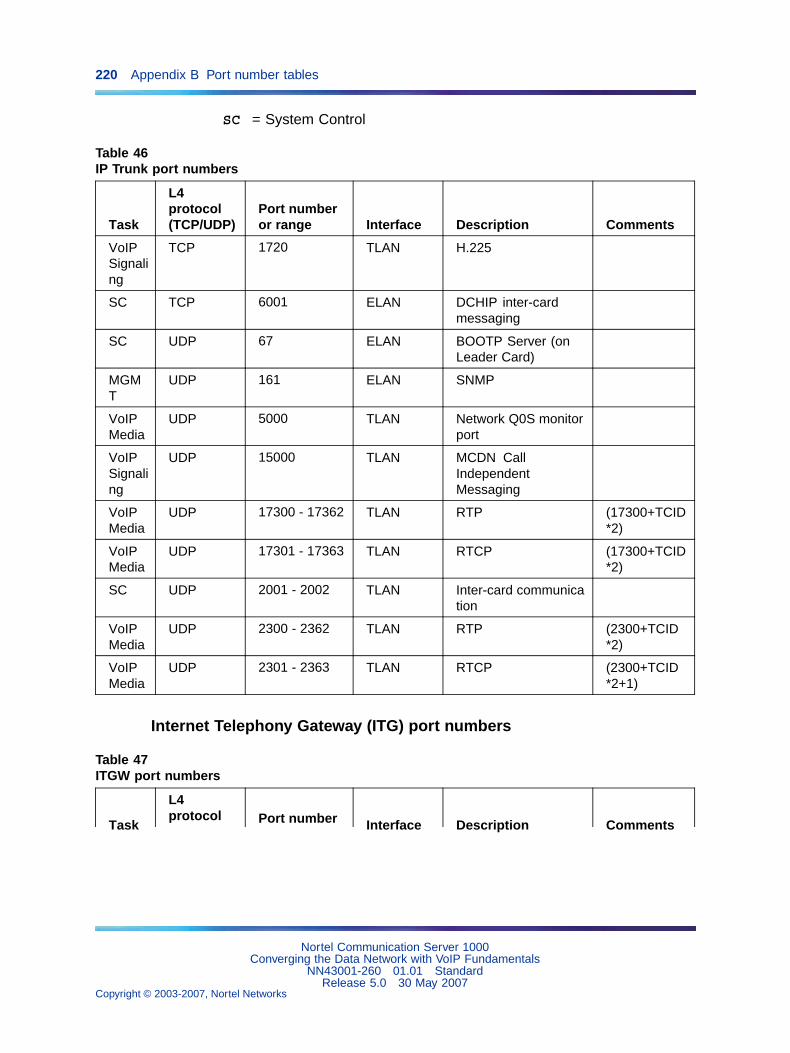
220 Appendix B Port number tables
SC = System Control
Table 46IP Trunk port numbers
Task
L4protocol(TCP/UDP)
Port numberor range Interface Description Comments
VoIPSignaling
TCP 1720 TLAN H.225
SC TCP 6001 ELAN DCHIP inter-cardmessaging
SC UDP 67 ELAN BOOTP Server (onLeader Card)
MGMT
UDP 161 ELAN SNMP
VoIPMedia
UDP 5000 TLAN Network Q0S monitorport
VoIPSignaling
UDP 15000 TLAN MCDN CallIndependentMessaging
VoIPMedia
UDP 17300 - 17362 TLAN RTP (17300+TCID*2)
VoIPMedia
UDP 17301 - 17363 TLAN RTCP (17300+TCID*2)
SC UDP 2001 - 2002 TLAN Inter-card communication
VoIPMedia
UDP 2300 - 2362 TLAN RTP (2300+TCID*2)
VoIPMedia
UDP 2301 - 2363 TLAN RTCP (2300+TCID*2+1)
Internet Telephony Gateway (ITG) port numbers
Table 47ITGW port numbers
Task
L4protocol Port number Interface Description Comments
Nortel Communication Server 1000Converging the Data Network with VoIP Fundamentals
NN43001-260 01.01 StandardRelease 5.0 30 May 2007
Copyright © 2003-2007, Nortel Networks
.
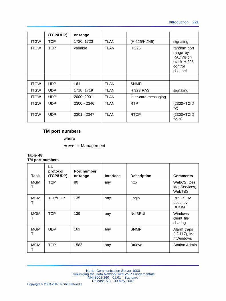
Introduction 221
(TCP/UDP) or range
ITGW TCP 1720, 1723 TLAN (H.225/H.245) signaling
ITGW TCP variable TLAN H.225 random portrange byRADVisionstack H.225controlchannel
ITGW UDP 161 TLAN SNMP
ITGW UDP 1718, 1719 TLAN H.323 RAS signaling
ITGW UDP 2000, 2001 TLAN inter-card messaging
ITGW UDP 2300 - 2346 TLAN RTP (2300+TCID*2)
ITGW UDP 2301 - 2347 TLAN RTCP (2300+TCID*2+1)
TM port numbers
where
MGMT = Management
Table 48TM port numbers
Task
L4protocol(TCP/UDP)
Port numberor range Interface Description Comments
MGMT
TCP 80 any http WebCS, DesktopServices,WebTBS
MGMT
TCP/UDP 135 any Login RPC SCMused byDCOM
MGMT
TCP 139 any NetBEUI Windowsclient filesharing
MGMT
UDP 162 any SNMP Alarm traps(LD117), MaintWindows
MGMT
TCP 1583 any Btrieve Station Admin
Nortel Communication Server 1000Converging the Data Network with VoIP Fundamentals
NN43001-260 01.01 StandardRelease 5.0 30 May 2007
Copyright © 2003-2007, Nortel Networks
.
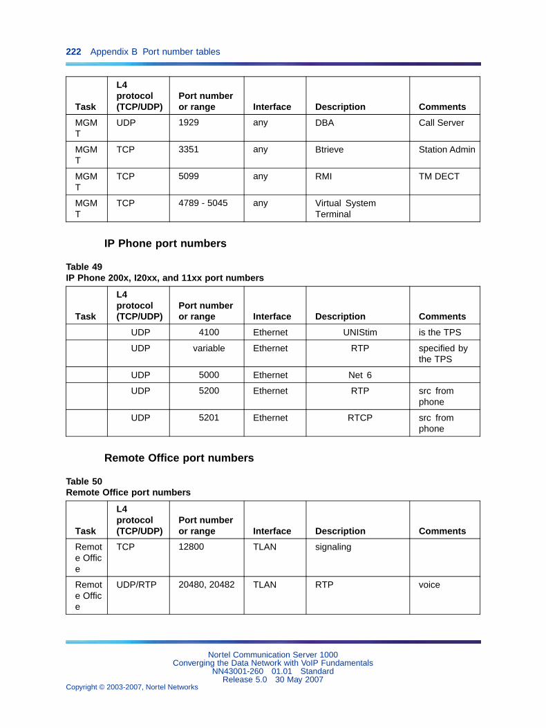
222 Appendix B Port number tables
Task
L4protocol(TCP/UDP)
Port numberor range Interface Description Comments
MGMT
UDP 1929 any DBA Call Server
MGMT
TCP 3351 any Btrieve Station Admin
MGMT
TCP 5099 any RMI TM DECT
MGMT
TCP 4789 - 5045 any Virtual SystemTerminal
IP Phone port numbers
Table 49IP Phone 200x, I20xx, and 11xx port numbers
Task
L4protocol(TCP/UDP)
Port numberor range Interface Description Comments
UDP 4100 Ethernet UNIStim is the TPS
UDP variable Ethernet RTP specified bythe TPS
UDP 5000 Ethernet Net 6
UDP 5200 Ethernet RTP src fromphone
UDP 5201 Ethernet RTCP src fromphone
Remote Office port numbers
Table 50Remote Office port numbers
Task
L4protocol(TCP/UDP)
Port numberor range Interface Description Comments
Remote Office
TCP 12800 TLAN signaling
Remote Office
UDP/RTP 20480, 20482 TLAN RTP voice
Nortel Communication Server 1000Converging the Data Network with VoIP Fundamentals
NN43001-260 01.01 StandardRelease 5.0 30 May 2007
Copyright © 2003-2007, Nortel Networks
.
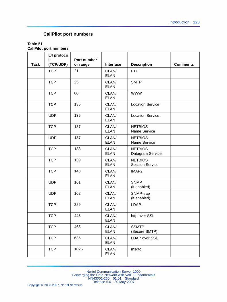
Introduction 223
CallPilot port numbers
Table 51CallPilot port numbers
Task
L4 protocol(TCP/UDP)
Port numberor range Interface Description Comments
TCP 21 CLAN/ELAN
FTP
TCP 25 CLAN/ELAN
SMTP
TCP 80 CLAN/ELAN
WWW
TCP 135 CLAN/ELAN
Location Service
UDP 135 CLAN/ELAN
Location Service
TCP 137 CLAN/ELAN
NETBIOSName Service
UDP 137 CLAN/ELAN
NETBIOSName Service
TCP 138 CLAN/ELAN
NETBIOSDatagram Service
TCP 139 CLAN/ELAN
NETBIOSSession Service
TCP 143 CLAN/ELAN
IMAP2
UDP 161 CLAN/ELAN
SNMP(if enabled)
UDP 162 CLAN/ELAN
SNMP-trap(if enabled)
TCP 389 CLAN/ELAN
LDAP
TCP 443 CLAN/ELAN
http over SSL
TCP 465 CLAN/ELAN
SSMTP(Secure SMTP)
TCP 636 CLAN/ELAN
LDAP over SSL
TCP 1025 CLAN/ELAN
msdtc
Nortel Communication Server 1000Converging the Data Network with VoIP Fundamentals
NN43001-260 01.01 StandardRelease 5.0 30 May 2007
Copyright © 2003-2007, Nortel Networks
.
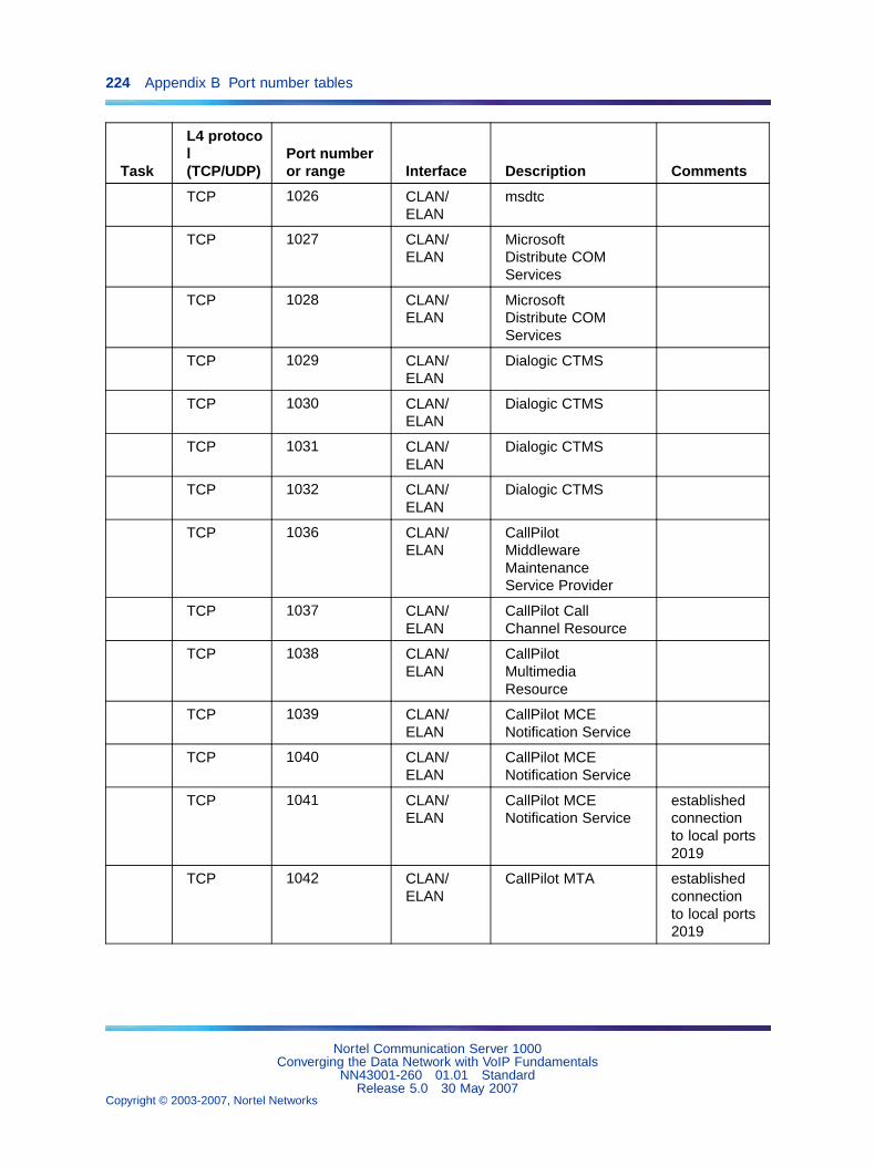
224 Appendix B Port number tables
Task
L4 protocol(TCP/UDP)
Port numberor range Interface Description Comments
TCP 1026 CLAN/ELAN
msdtc
TCP 1027 CLAN/ELAN
MicrosoftDistribute COMServices
TCP 1028 CLAN/ELAN
MicrosoftDistribute COMServices
TCP 1029 CLAN/ELAN
Dialogic CTMS
TCP 1030 CLAN/ELAN
Dialogic CTMS
TCP 1031 CLAN/ELAN
Dialogic CTMS
TCP 1032 CLAN/ELAN
Dialogic CTMS
TCP 1036 CLAN/ELAN
CallPilotMiddlewareMaintenanceService Provider
TCP 1037 CLAN/ELAN
CallPilot CallChannel Resource
TCP 1038 CLAN/ELAN
CallPilotMultimediaResource
TCP 1039 CLAN/ELAN
CallPilot MCENotification Service
TCP 1040 CLAN/ELAN
CallPilot MCENotification Service
TCP 1041 CLAN/ELAN
CallPilot MCENotification Service
establishedconnectionto local ports2019
TCP 1042 CLAN/ELAN
CallPilot MTA establishedconnectionto local ports2019
Nortel Communication Server 1000Converging the Data Network with VoIP Fundamentals
NN43001-260 01.01 StandardRelease 5.0 30 May 2007
Copyright © 2003-2007, Nortel Networks
.
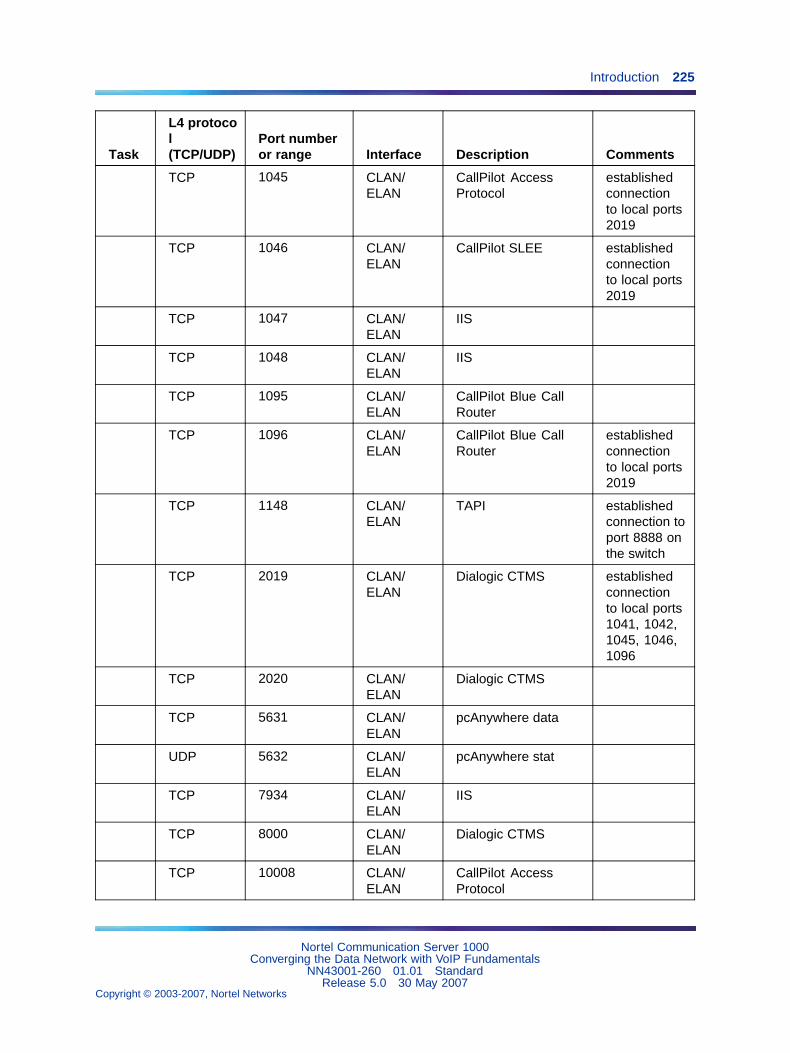
Introduction 225
Task
L4 protocol(TCP/UDP)
Port numberor range Interface Description Comments
TCP 1045 CLAN/ELAN
CallPilot AccessProtocol
establishedconnectionto local ports2019
TCP 1046 CLAN/ELAN
CallPilot SLEE establishedconnectionto local ports2019
TCP 1047 CLAN/ELAN
IIS
TCP 1048 CLAN/ELAN
IIS
TCP 1095 CLAN/ELAN
CallPilot Blue CallRouter
TCP 1096 CLAN/ELAN
CallPilot Blue CallRouter
establishedconnectionto local ports2019
TCP 1148 CLAN/ELAN
TAPI establishedconnection toport 8888 onthe switch
TCP 2019 CLAN/ELAN
Dialogic CTMS establishedconnectionto local ports1041, 1042,1045, 1046,1096
TCP 2020 CLAN/ELAN
Dialogic CTMS
TCP 5631 CLAN/ELAN
pcAnywhere data
UDP 5632 CLAN/ELAN
pcAnywhere stat
TCP 7934 CLAN/ELAN
IIS
TCP 8000 CLAN/ELAN
Dialogic CTMS
TCP 10008 CLAN/ELAN
CallPilot AccessProtocol
Nortel Communication Server 1000Converging the Data Network with VoIP Fundamentals
NN43001-260 01.01 StandardRelease 5.0 30 May 2007
Copyright © 2003-2007, Nortel Networks
.
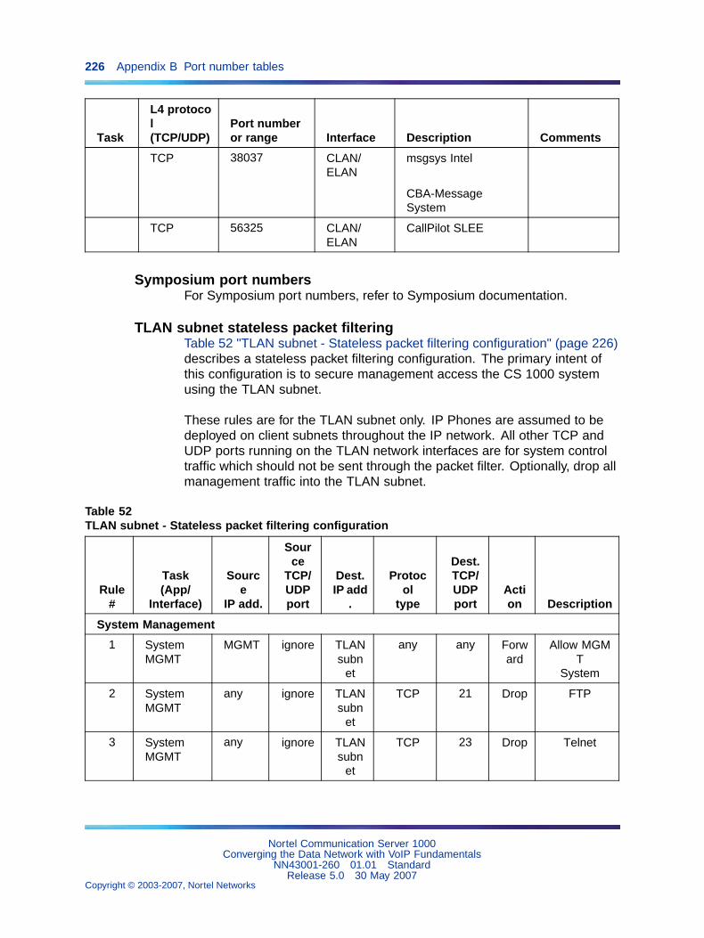
226 Appendix B Port number tables
Task
L4 protocol(TCP/UDP)
Port numberor range Interface Description Comments
TCP 38037 CLAN/ELAN
msgsys Intel
CBA-MessageSystem
TCP 56325 CLAN/ELAN
CallPilot SLEE
Symposium port numbersFor Symposium port numbers, refer to Symposium documentation.
TLAN subnet stateless packet filteringTable 52 "TLAN subnet - Stateless packet filtering configuration" (page 226)describes a stateless packet filtering configuration. The primary intent ofthis configuration is to secure management access the CS 1000 systemusing the TLAN subnet.
These rules are for the TLAN subnet only. IP Phones are assumed to bedeployed on client subnets throughout the IP network. All other TCP andUDP ports running on the TLAN network interfaces are for system controltraffic which should not be sent through the packet filter. Optionally, drop allmanagement traffic into the TLAN subnet.
Table 52TLAN subnet - Stateless packet filtering configuration
Rule#
Task(App/
Interface)
Source
IP add.
Source
TCP/UDPport
Dest.IP add
.
Protocol
type
Dest.TCP/UDPport
Action Description
System Management
1 SystemMGMT
MGMT ignore TLANsubn
et
any any Forward
Allow MGMT
System
2 SystemMGMT
any ignore TLANsubn
et
TCP 21 Drop FTP
3 SystemMGMT
any ignore TLANsubn
et
TCP 23 Drop Telnet
Nortel Communication Server 1000Converging the Data Network with VoIP Fundamentals
NN43001-260 01.01 StandardRelease 5.0 30 May 2007
Copyright © 2003-2007, Nortel Networks
.
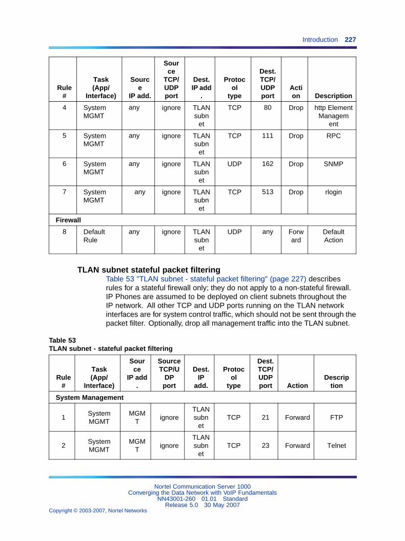
Introduction 227
Rule#
Task(App/
Interface)
Source
IP add.
Source
TCP/UDPport
Dest.IP add
.
Protocol
type
Dest.TCP/UDPport
Action Description
4 SystemMGMT
any ignore TLANsubn
et
TCP 80 Drop http ElementManagem
ent
5 SystemMGMT
any ignore TLANsubn
et
TCP 111 Drop RPC
6 SystemMGMT
any ignore TLANsubn
et
UDP 162 Drop SNMP
7 SystemMGMT
any ignore TLANsubn
et
TCP 513 Drop rlogin
Firewall
8 DefaultRule
any ignore TLANsubn
et
UDP any Forward
DefaultAction
TLAN subnet stateful packet filteringTable 53 "TLAN subnet - stateful packet filtering" (page 227) describesrules for a stateful firewall only; they do not apply to a non-stateful firewall.IP Phones are assumed to be deployed on client subnets throughout theIP network. All other TCP and UDP ports running on the TLAN networkinterfaces are for system control traffic, which should not be sent through thepacket filter. Optionally, drop all management traffic into the TLAN subnet.
Table 53TLAN subnet - stateful packet filtering
Rule#
Task(App/
Interface)
Source
IP add.
SourceTCP/U
DPport
Dest.IP
add.
Protocol
type
Dest.TCP/UDPport Action
Description
System Management
1SystemMGMT
MGMT
ignoreTLANsubn
etTCP 21 Forward FTP
2SystemMGMT
MGMT
ignoreTLANsubn
etTCP 23 Forward Telnet
Nortel Communication Server 1000Converging the Data Network with VoIP Fundamentals
NN43001-260 01.01 StandardRelease 5.0 30 May 2007
Copyright © 2003-2007, Nortel Networks
.
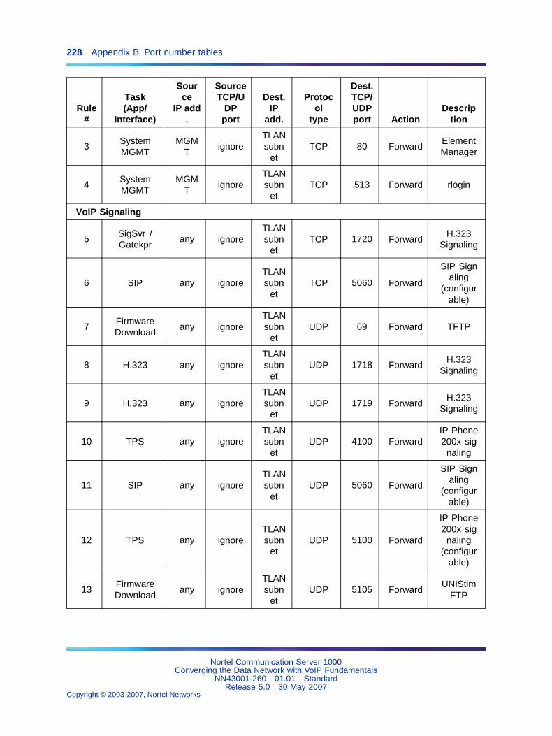
228 Appendix B Port number tables
Rule#
Task(App/
Interface)
Source
IP add.
SourceTCP/U
DPport
Dest.IP
add.
Protocol
type
Dest.TCP/UDPport Action
Description
3SystemMGMT
MGMT
ignoreTLANsubn
etTCP 80 Forward
ElementManager
4SystemMGMT
MGMT
ignoreTLANsubn
etTCP 513 Forward rlogin
VoIP Signaling
5SigSvr /Gatekpr
any ignoreTLANsubn
etTCP 1720 Forward
H.323Signaling
6 SIP any ignoreTLANsubn
etTCP 5060 Forward
SIP Signaling
(configurable)
7FirmwareDownload
any ignoreTLANsubn
etUDP 69 Forward TFTP
8 H.323 any ignoreTLANsubn
etUDP 1718 Forward
H.323Signaling
9 H.323 any ignoreTLANsubn
etUDP 1719 Forward
H.323Signaling
10 TPS any ignoreTLANsubn
etUDP 4100 Forward
IP Phone200x sig
naling
11 SIP any ignoreTLANsubn
etUDP 5060 Forward
SIP Signaling
(configurable)
12 TPS any ignoreTLANsubn
etUDP 5100 Forward
IP Phone200x sig
naling(configur
able)
13FirmwareDownload
any ignoreTLANsubn
etUDP 5105 Forward
UNIStimFTP
Nortel Communication Server 1000Converging the Data Network with VoIP Fundamentals
NN43001-260 01.01 StandardRelease 5.0 30 May 2007
Copyright © 2003-2007, Nortel Networks
.
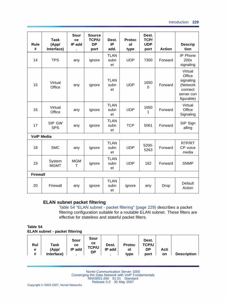
Introduction 229
Rule#
Task(App/
Interface)
Source
IP add.
SourceTCP/U
DPport
Dest.IP
add.
Protocol
type
Dest.TCP/UDPport Action
Description
14 TPS any ignoreTLANsubn
etUDP 7300 Forward
IP Phone200x
signaling
15VirtualOffice
any ignoreTLANsubn
etUDP
16500
Forward
VirtualOffice
signaling(Networkconnect
server configurable)
16VirtualOffice
any ignoreTLANsubn
etUDP
16501
ForwardVirtualOffice
Signaling
17SIP GW
SPSany ignore
TLANsubn
etTCP 5061 Forward
SIP Signalling
VoIP Media
18 SMC any ignoreTLANsubn
etUDP
5200-5263
ForwardRTP/RTCP voice
media
19SystemMGMT
MGMT
ignoreTLANsubn
etUDP 162 Forward SNMP
Firewall
20 Firewall any ignoreTLANsubn
etignore any Drop
DefaultAction
ELAN subnet packet filteringTable 54 "ELAN subnet - packet filtering" (page 229) describes a packetfiltering configuration suitable for a routable ELAN subnet. These filters areeffective for stateless and stateful packet filters.
Table 54ELAN subnet - packet filtering
Rule#
Task(App/
Interface)
Source
IP add.
Source
TCP/UDP
Dest.IP add
.
Protocol
type
Dest.TCP/U
DPport
Action Description
Nortel Communication Server 1000Converging the Data Network with VoIP Fundamentals
NN43001-260 01.01 StandardRelease 5.0 30 May 2007
Copyright © 2003-2007, Nortel Networks
.
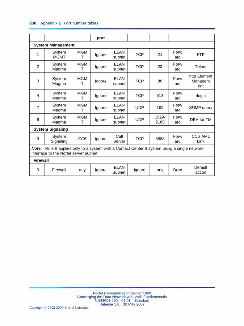
230 Appendix B Port number tables
port
System Management
1SystemMGMT
MGMT
IgnoreELANsubnet
TCP 21Forward
FTP
2SystemMagma
MGMT
IgnoreELANsubnet
TCP 23Forward
Telnet
3SystemMagma
MGMT
IgnoreELANsubnet
TCP 80Forward
http ElementManagem
ent
4SystemMagma
MGMT
IgnoreELANsubnet
TCP 513Forward
rlogin
7SystemMagma
MGMT
IgnoreELANsubnet
UDP 162Forward
SNMP query
8SystemMagma
MGMT
IgnoreELANsubnet
UDP1929-2185
Forward
DBA for TM
System Signaling
9System
SignalingCC6 ignore
CallServer
TCP 8888Forward
CC6 AMLLink
Note: Rule 9 applies only to a system with a Contact Center 6 system using a single networkinterface to the Nortel server subnet.
Firewall
9 Firewall any IgnoreELANsubnet
ignore any DropDefaultaction
Nortel Communication Server 1000Converging the Data Network with VoIP Fundamentals
NN43001-260 01.01 StandardRelease 5.0 30 May 2007
Copyright © 2003-2007, Nortel Networks
.
231
Appendix CDHCP supplemental information
ContentsThis section contains information on the following topics:
"Introduction to DHCP" (page 231)
"DHCP messages" (page 232)
"DHCP message format" (page 232)
"DHCP message exchange" (page 233)
"DHCP options" (page 234)
"Vendor Specific/Encapsulated option" (page 234)
"Site Specific option" (page 235)
"IP acquisition sequence" (page 235)
"Case 1" (page 235)
"Case 2" (page 236)
"Case 3" (page 237)
"Multiple DHCPOFFERS" (page 238)
"IP Phone support for DHCP" (page 239)
"Full DCHP" (page 239)
"Partial DCHP" (page 243)
"DHCP Auto Discovery" (page 243)s
Introduction to DHCPTo understand how the IP Phones 200x and the IP Softphone 2050 acquirethe needed network configuration parameters automatically, the followingsection briefly describes the Dynamic Host Configuration Protocol (DHCP).
Read this section unfamiliar with DHCP. Topics discussed are helpful forthe configuration and future maintenance of the DHCP server and ensurecorrect implementation with IP Phones.
Nortel Communication Server 1000Converging the Data Network with VoIP Fundamentals
NN43001-260 01.01 StandardRelease 5.0 30 May 2007
Copyright © 2003-2007, Nortel Networks
.
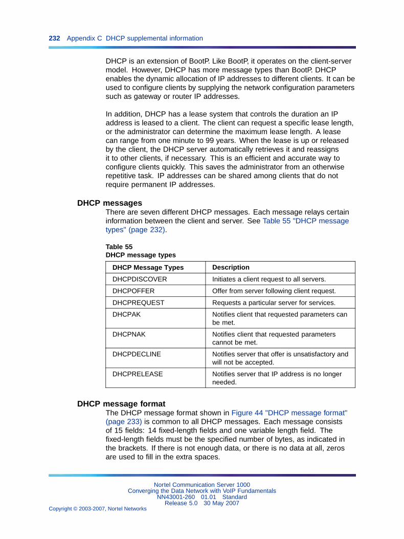
232 Appendix C DHCP supplemental information
DHCP is an extension of BootP. Like BootP, it operates on the client-servermodel. However, DHCP has more message types than BootP. DHCPenables the dynamic allocation of IP addresses to different clients. It can beused to configure clients by supplying the network configuration parameterssuch as gateway or router IP addresses.
In addition, DHCP has a lease system that controls the duration an IPaddress is leased to a client. The client can request a specific lease length,or the administrator can determine the maximum lease length. A leasecan range from one minute to 99 years. When the lease is up or releasedby the client, the DHCP server automatically retrieves it and reassignsit to other clients, if necessary. This is an efficient and accurate way toconfigure clients quickly. This saves the administrator from an otherwiserepetitive task. IP addresses can be shared among clients that do notrequire permanent IP addresses.
DHCP messagesThere are seven different DHCP messages. Each message relays certaininformation between the client and server. See Table 55 "DHCP messagetypes" (page 232).
Table 55DHCP message types
DHCP Message Types Description
DHCPDISCOVER Initiates a client request to all servers.
DHCPOFFER Offer from server following client request.
DHCPREQUEST Requests a particular server for services.
DHCPAK Notifies client that requested parameters canbe met.
DHCPNAK Notifies client that requested parameterscannot be met.
DHCPDECLINE Notifies server that offer is unsatisfactory andwill not be accepted.
DHCPRELEASE Notifies server that IP address is no longerneeded.
DHCP message formatThe DHCP message format shown in Figure 44 "DHCP message format"(page 233) is common to all DHCP messages. Each message consistsof 15 fields: 14 fixed-length fields and one variable length field. Thefixed-length fields must be the specified number of bytes, as indicated inthe brackets. If there is not enough data, or there is no data at all, zerosare used to fill in the extra spaces.
Nortel Communication Server 1000Converging the Data Network with VoIP Fundamentals
NN43001-260 01.01 StandardRelease 5.0 30 May 2007
Copyright © 2003-2007, Nortel Networks
.
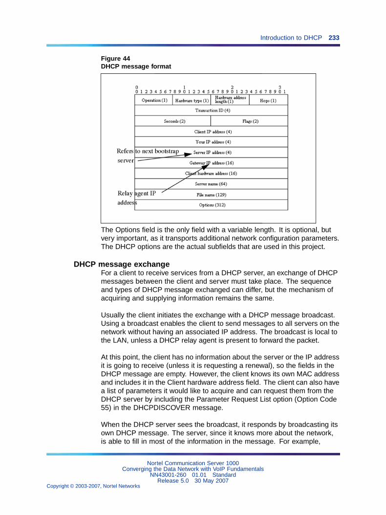
Introduction to DHCP 233
Figure 44DHCP message format
The Options field is the only field with a variable length. It is optional, butvery important, as it transports additional network configuration parameters.The DHCP options are the actual subfields that are used in this project.
DHCP message exchangeFor a client to receive services from a DHCP server, an exchange of DHCPmessages between the client and server must take place. The sequenceand types of DHCP message exchanged can differ, but the mechanism ofacquiring and supplying information remains the same.
Usually the client initiates the exchange with a DHCP message broadcast.Using a broadcast enables the client to send messages to all servers on thenetwork without having an associated IP address. The broadcast is local tothe LAN, unless a DHCP relay agent is present to forward the packet.
At this point, the client has no information about the server or the IP addressit is going to receive (unless it is requesting a renewal), so the fields in theDHCP message are empty. However, the client knows its own MAC addressand includes it in the Client hardware address field. The client can also havea list of parameters it would like to acquire and can request them from theDHCP server by including the Parameter Request List option (Option Code55) in the DHCPDISCOVER message.
When the DHCP server sees the broadcast, it responds by broadcasting itsown DHCP message. The server, since it knows more about the network,is able to fill in most of the information in the message. For example,
Nortel Communication Server 1000Converging the Data Network with VoIP Fundamentals
NN43001-260 01.01 StandardRelease 5.0 30 May 2007
Copyright © 2003-2007, Nortel Networks
.
234 Appendix C DHCP supplemental information
information such as the server IP address and gateway IP address areincluded in their respective fields. Since the client does not have an IPaddress yet, the server uses the client’s MAC address to uniquely identify it.When the client sees the broadcast, it matches its MAC address against theone in the message.
DHCP optionsDHCP options are the sub-fields of the Options field. They carry additionalnetwork configuration information requested by the client such as the IPaddress lease length and the subnet mask.
Each DHCP option has an associated option code and a format for carryingdata. Usually the format is as follows:
Option code Length Data
There are two categories of DHCP options: standard and non-standard.The standard options are predefined by the industry. The non-standardoptions are user-defined to fit the needs of a particular vendor or site.
There are a total of 255 DHCP option codes where option codes 0 and255 are reserved, 1 – 77 are predefined, 1 – 254 can be used for VendorSpecific Options, and 128 – 254 are designated for Site Specific Options.This arrangement enables future expansion and is used as a guidelinefor choosing option codes.
Vendor Specific/Encapsulated optionThe Vendor Specific DHCP options are vendor-defined options for carryingvendor-related information. It is possible to override predefined standardoptions; however, doing so can cause conflict when used with componentsthat follow the industry standard.
A useful option is the standard Vendor Encapsulated option – code 43. Itis used to encapsulate other DHCP options as sub-options. For example,the IP Phone 2004 requires vendor specific Voice Gateway Media Cardinformation. The vendor, Nortel, decided to carry this information in one ofseveral Site Specific options and then encapsulate it into option 43. Sincethe information is specific to a Nortel product, it is vendor-specific. Onceencapsulated, the information appears as one or more sub-options insideoption 43, which the IP Phone decodes.
Nortel Communication Server 1000Converging the Data Network with VoIP Fundamentals
NN43001-260 01.01 StandardRelease 5.0 30 May 2007
Copyright © 2003-2007, Nortel Networks
.
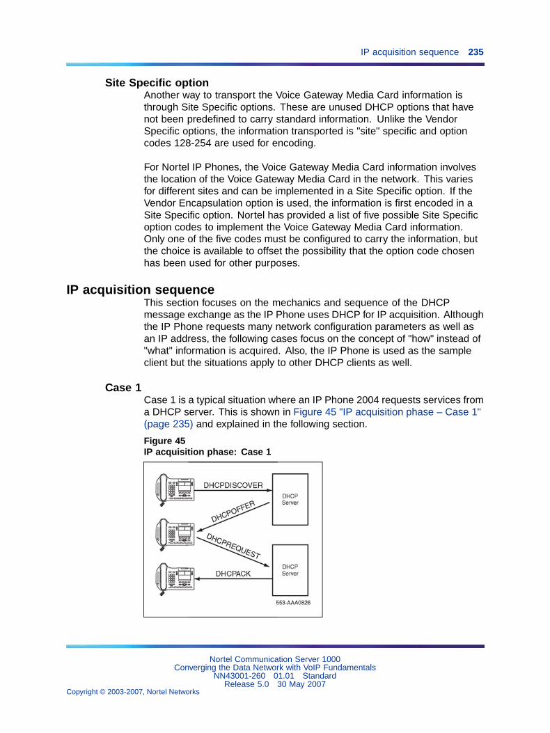
IP acquisition sequence 235
Site Specific optionAnother way to transport the Voice Gateway Media Card information isthrough Site Specific options. These are unused DHCP options that havenot been predefined to carry standard information. Unlike the VendorSpecific options, the information transported is "site" specific and optioncodes 128-254 are used for encoding.
For Nortel IP Phones, the Voice Gateway Media Card information involvesthe location of the Voice Gateway Media Card in the network. This variesfor different sites and can be implemented in a Site Specific option. If theVendor Encapsulation option is used, the information is first encoded in aSite Specific option. Nortel has provided a list of five possible Site Specificoption codes to implement the Voice Gateway Media Card information.Only one of the five codes must be configured to carry the information, butthe choice is available to offset the possibility that the option code chosenhas been used for other purposes.
IP acquisition sequenceThis section focuses on the mechanics and sequence of the DHCPmessage exchange as the IP Phone uses DHCP for IP acquisition. Althoughthe IP Phone requests many network configuration parameters as well asan IP address, the following cases focus on the concept of "how" instead of"what" information is acquired. Also, the IP Phone is used as the sampleclient but the situations apply to other DHCP clients as well.
Case 1Case 1 is a typical situation where an IP Phone 2004 requests services froma DHCP server. This is shown in Figure 45 "IP acquisition phase – Case 1"(page 235) and explained in the following section.
Figure 45IP acquisition phase: Case 1
Nortel Communication Server 1000Converging the Data Network with VoIP Fundamentals
NN43001-260 01.01 StandardRelease 5.0 30 May 2007
Copyright © 2003-2007, Nortel Networks
.
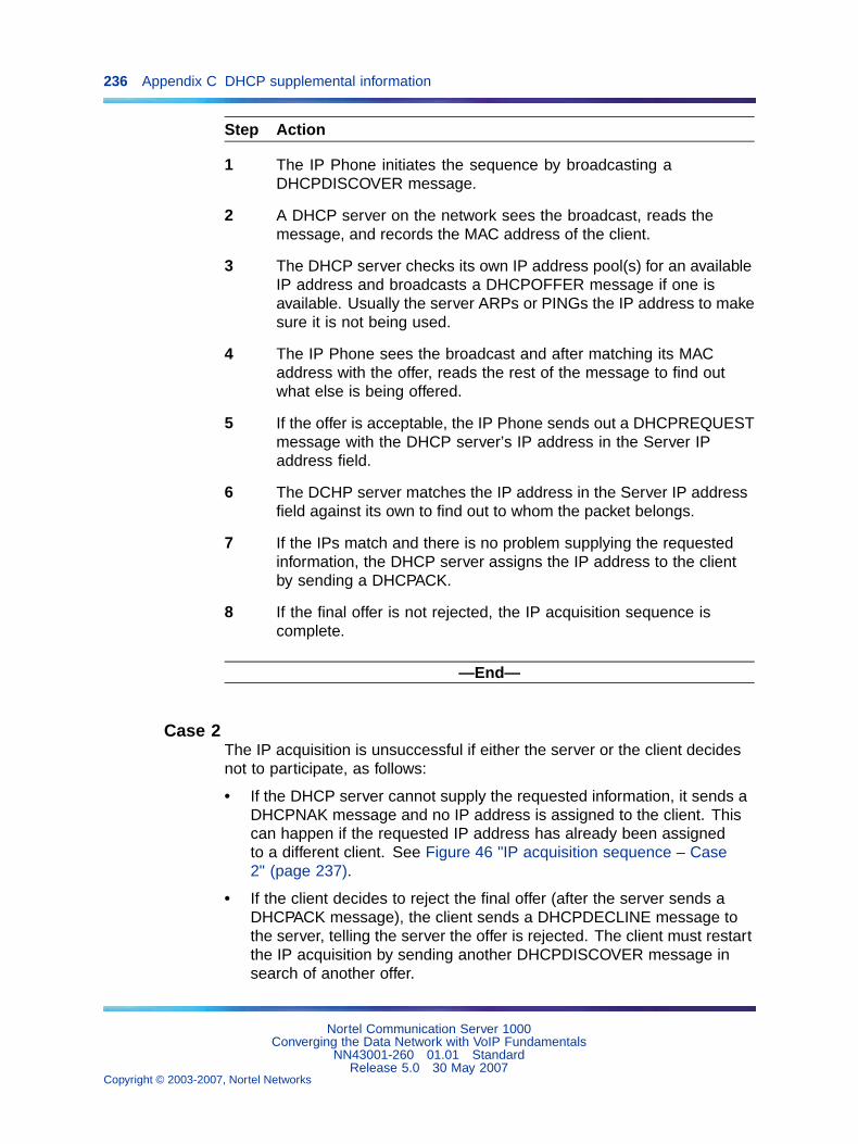
236 Appendix C DHCP supplemental information
Step Action
1 The IP Phone initiates the sequence by broadcasting aDHCPDISCOVER message.
2 A DHCP server on the network sees the broadcast, reads themessage, and records the MAC address of the client.
3 The DHCP server checks its own IP address pool(s) for an availableIP address and broadcasts a DHCPOFFER message if one isavailable. Usually the server ARPs or PINGs the IP address to makesure it is not being used.
4 The IP Phone sees the broadcast and after matching its MACaddress with the offer, reads the rest of the message to find outwhat else is being offered.
5 If the offer is acceptable, the IP Phone sends out a DHCPREQUESTmessage with the DHCP server’s IP address in the Server IPaddress field.
6 The DCHP server matches the IP address in the Server IP addressfield against its own to find out to whom the packet belongs.
7 If the IPs match and there is no problem supplying the requestedinformation, the DHCP server assigns the IP address to the clientby sending a DHCPACK.
8 If the final offer is not rejected, the IP acquisition sequence iscomplete.
—End—
Case 2The IP acquisition is unsuccessful if either the server or the client decidesnot to participate, as follows:
• If the DHCP server cannot supply the requested information, it sends aDHCPNAK message and no IP address is assigned to the client. Thiscan happen if the requested IP address has already been assignedto a different client. See Figure 46 "IP acquisition sequence – Case2" (page 237).
• If the client decides to reject the final offer (after the server sends aDHCPACK message), the client sends a DHCPDECLINE message tothe server, telling the server the offer is rejected. The client must restartthe IP acquisition by sending another DHCPDISCOVER message insearch of another offer.
Nortel Communication Server 1000Converging the Data Network with VoIP Fundamentals
NN43001-260 01.01 StandardRelease 5.0 30 May 2007
Copyright © 2003-2007, Nortel Networks
.
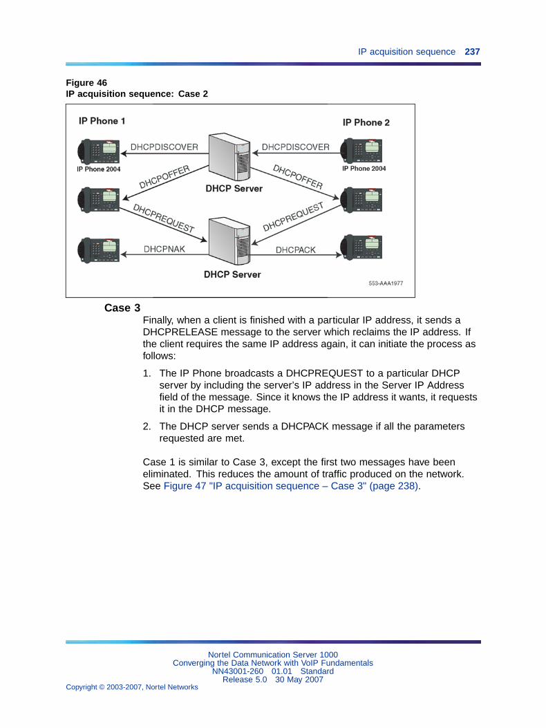
IP acquisition sequence 237
Figure 46IP acquisition sequence: Case 2
Case 3Finally, when a client is finished with a particular IP address, it sends aDHCPRELEASE message to the server which reclaims the IP address. Ifthe client requires the same IP address again, it can initiate the process asfollows:
1. The IP Phone broadcasts a DHCPREQUEST to a particular DHCPserver by including the server’s IP address in the Server IP Addressfield of the message. Since it knows the IP address it wants, it requestsit in the DHCP message.
2. The DHCP server sends a DHCPACK message if all the parametersrequested are met.
Case 1 is similar to Case 3, except the first two messages have beeneliminated. This reduces the amount of traffic produced on the network.See Figure 47 "IP acquisition sequence – Case 3" (page 238).
Nortel Communication Server 1000Converging the Data Network with VoIP Fundamentals
NN43001-260 01.01 StandardRelease 5.0 30 May 2007
Copyright © 2003-2007, Nortel Networks
.
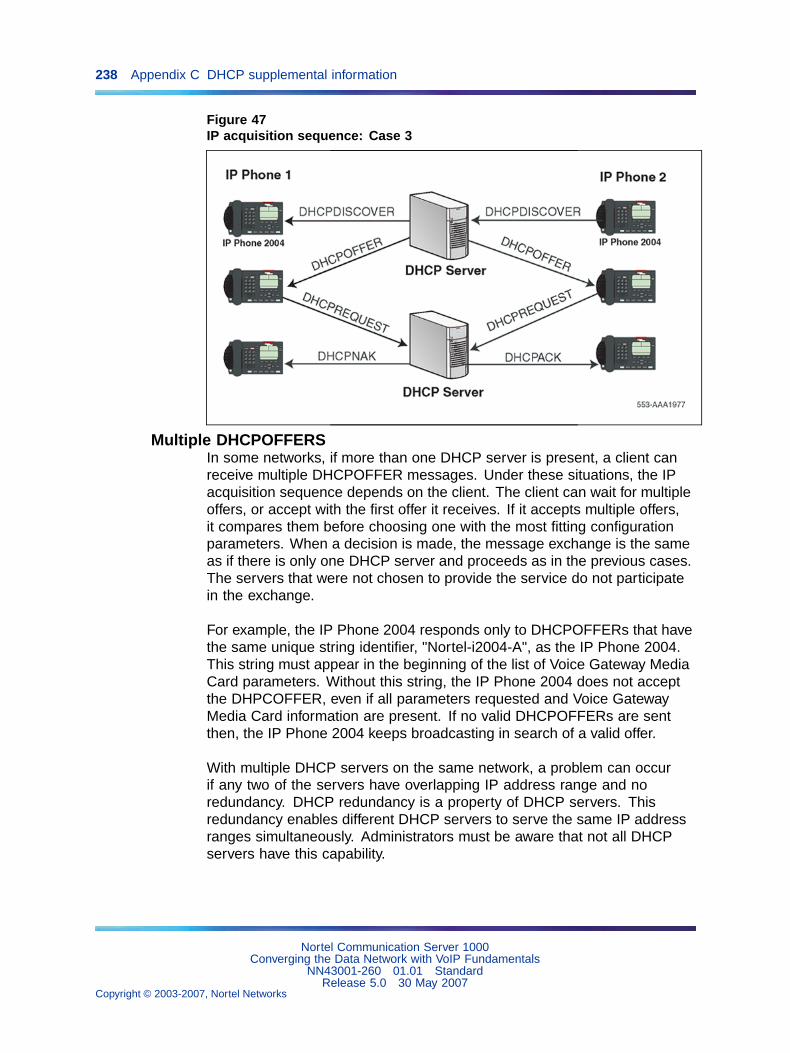
238 Appendix C DHCP supplemental information
Figure 47IP acquisition sequence: Case 3
Multiple DHCPOFFERSIn some networks, if more than one DHCP server is present, a client canreceive multiple DHCPOFFER messages. Under these situations, the IPacquisition sequence depends on the client. The client can wait for multipleoffers, or accept with the first offer it receives. If it accepts multiple offers,it compares them before choosing one with the most fitting configurationparameters. When a decision is made, the message exchange is the sameas if there is only one DHCP server and proceeds as in the previous cases.The servers that were not chosen to provide the service do not participatein the exchange.
For example, the IP Phone 2004 responds only to DHCPOFFERs that havethe same unique string identifier, "Nortel-i2004-A", as the IP Phone 2004.This string must appear in the beginning of the list of Voice Gateway MediaCard parameters. Without this string, the IP Phone 2004 does not acceptthe DHPCOFFER, even if all parameters requested and Voice GatewayMedia Card information are present. If no valid DHCPOFFERs are sentthen, the IP Phone 2004 keeps broadcasting in search of a valid offer.
With multiple DHCP servers on the same network, a problem can occurif any two of the servers have overlapping IP address range and noredundancy. DHCP redundancy is a property of DHCP servers. Thisredundancy enables different DHCP servers to serve the same IP addressranges simultaneously. Administrators must be aware that not all DHCPservers have this capability.
Nortel Communication Server 1000Converging the Data Network with VoIP Fundamentals
NN43001-260 01.01 StandardRelease 5.0 30 May 2007
Copyright © 2003-2007, Nortel Networks
.
IP Phone support for DHCP 239
IP Phone support for DHCPThis section covers the three uses of DHCP (Full, Partial, and VLAN AutoDiscovery) by IP Phones 2002, 2004, and 2007.
An "IP Phone 2004-aware" DHCP server is needed only for the Full DHCPand VLAN Auto discovery. An IP Phone can obtain its IP address andsubnet mask using Partial DHCP. The "IP Phone 2004 aware" part returnsthe Node IP and registration port number. In the case of the DHCP AutoDiscovery, it returns the VLAN IDs. Separate DHCP vendor-specific entriesare needed for the Full DHCP data and the VLAN Auto Discovery data.When using the VLAN Auto Discovery, both Full DHCP and VLAN AutoDiscovery must be configured. Full DHCP and Auto VLAN are implementedas separate functions in the IP Phone firmware. However, in practice, FullDHCP and Auto VLAN are frequently used together.
Full DCHPDHCP support in the IP Phone requires sending a "Class Identifier"option with the value "Nortel-i2004-A" in each DHCP DHCPOFFER andDHCPACK message. Additionally, the telephone checks for either a VendorSpecific option message with a specific, unique to Nortel IP Phone 2004,encapsulated sub-type, or a Site Specific DHCP option.
In either case, an IP Phone 2004-specific option must be returned by theIP Phone 2004 aware DHCP server in all Offer and Acknowledgement(ACK) messages. The IP Phone uses this option’s data it to configure theinformation required to connect to the TPS.
The DHCP response is parsed to extract the IP Phone’s IP address, subnetmask, and gateway IP address. The vendor specific field is then parsed toextract the Server 1 (minimum) and optionally Server 2. By default, Server 1is always assumed to be the "primary" server after a DHCP session.
For the IP Phone to accept Offers/Acks, the messages must contain allof the following:
• A router option (needs a default router to function)
• A subnet mask option
• A Vendor Specific option as specified below or a Site Specific optionas specified below.
— The initial DHCP implementation required only the Vendor Specificencapsulated sub-option. In inter-op testing with Windows NT (upto Service Release 4), it was discovered that Windows NT does notproperly adhere to RFC 1541. As a result this option is not possible.The implementation was changed to add support for either VendorSpecific sub-ops or Site Specific options. This new extension hasbeen tested and verified to work with Windows NT.
Nortel Communication Server 1000Converging the Data Network with VoIP Fundamentals
NN43001-260 01.01 StandardRelease 5.0 30 May 2007
Copyright © 2003-2007, Nortel Networks
.
240 Appendix C DHCP supplemental information
— The site-specific options are all DHCP options between 128 (0x80)and 254 (0xFE). These options are reserved for site specific useby the DHCP RFCs.
Format for IP Phone 2004 Terminal DHCPClass Identifier FieldAll IP Phones (IP Phones 2x and IP Softphone 2050) fill in the Class ID fieldof the DHCP Discovery and Request messages with the following:
"Nortel-i2004-A", where:
• ASCII encoded, NULL (0x00) terminated
• unique to IP Phone 2004
• "-A" uniquely identifies this version
Format for IP Phone 2004 Terminal DHCPEncapsulated Vendor Specific FieldThis sub-option must be encapsulated in a DHCP Vendor Specific Option(refer to RFC 1541 and RFC 1533) and returned by the DHCP server aspart of each DHCP OFFER and ACK message in order for the IP Phoneto accept these messages as valid.
The IP Phone parses this option’s data and use it to configure theinformation required to connect to the TPS.
Note 1: Either this encapsulated sub-option must be present, or asimilarly encoded site-specific option must be sent. See "Format of theEncapsulated Vendor Specific Sub-option field" (page 240). Configurethe DHCP server to send one or the other – not both.
Note 2: The choice of using either Vendor Specific or Site Specificoptions is provided to enable Windows NT DHCP servers to be usedwith the IP Phone. Windows NT servers do not properly implement theVendor Specific Option and as a result, Windows NT implementationsmust use the Site Specific version.
Format of the Encapsulated Vendor Specific Sub-option fieldThe format of the field is as follows:
• Type (1 octet): 5 choices are provided (0x80, 0x90, 0x9d, 0xbf, 0xfb[128, 144, 157, 191, 251]), allowing the IP Phone to operate when oneor more values is already in use by a different vendor. Select only oneTYPE byte.
• Length (1 octet): variable – depends on message content.
• Data (length octets): ASCII based with the following format:
Nortel-i2004 -A,iii.jjj.kkk.lll:ppppp,aaa,rrr;iii.jjj.kkk.lll:pppp,aaa,rrr.
Nortel Communication Server 1000Converging the Data Network with VoIP Fundamentals
NN43001-260 01.01 StandardRelease 5.0 30 May 2007
Copyright © 2003-2007, Nortel Networks
.
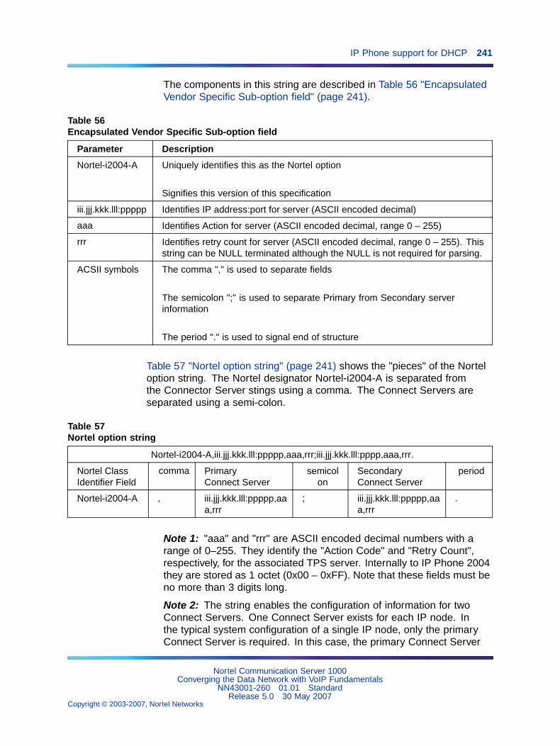
IP Phone support for DHCP 241
The components in this string are described in Table 56 "EncapsulatedVendor Specific Sub-option field" (page 241).
Table 56Encapsulated Vendor Specific Sub-option field
Parameter Description
Nortel-i2004-A Uniquely identifies this as the Nortel option
Signifies this version of this specification
iii.jjj.kkk.lll:ppppp Identifies IP address:port for server (ASCII encoded decimal)
aaa Identifies Action for server (ASCII encoded decimal, range 0 – 255)
rrr Identifies retry count for server (ASCII encoded decimal, range 0 – 255). Thisstring can be NULL terminated although the NULL is not required for parsing.
ACSII symbols The comma "," is used to separate fields
The semicolon ";" is used to separate Primary from Secondary serverinformation
The period "." is used to signal end of structure
Table 57 "Nortel option string" (page 241) shows the "pieces" of the Norteloption string. The Nortel designator Nortel-i2004-A is separated fromthe Connector Server stings using a comma. The Connect Servers areseparated using a semi-colon.
Table 57Nortel option string
Nortel-i2004-A,iii.jjj.kkk.lll:ppppp,aaa,rrr;iii.jjj.kkk.lll:pppp,aaa,rrr.
Nortel ClassIdentifier Field
comma PrimaryConnect Server
semicolon
SecondaryConnect Server
period
Nortel-i2004-A , iii.jjj.kkk.lll:ppppp,aaa,rrr
; iii.jjj.kkk.lll:ppppp,aaa,rrr
.
Note 1: "aaa" and "rrr" are ASCII encoded decimal numbers with arange of 0–255. They identify the "Action Code" and "Retry Count",respectively, for the associated TPS server. Internally to IP Phone 2004they are stored as 1 octet (0x00 – 0xFF). Note that these fields must beno more than 3 digits long.
Note 2: The string enables the configuration of information for twoConnect Servers. One Connect Server exists for each IP node. Inthe typical system configuration of a single IP node, only the primaryConnect Server is required. In this case, the primary Connect Server
Nortel Communication Server 1000Converging the Data Network with VoIP Fundamentals
NN43001-260 01.01 StandardRelease 5.0 30 May 2007
Copyright © 2003-2007, Nortel Networks
.
242 Appendix C DHCP supplemental information
string must be ended with a period (.) instead of a semi-colon (;). Forexample, "Nortel-i2004-A,iii.jjj.kkk.lll:ppppp,aaa,rrr."
If the secondary Connect Server portion of the string isspecified, then the string information is typically the sameas the primary Connect Server information. For example:"Nortel-i2004-A,iii.jjj.kkk.lll:ppppp,aaa,rrr;iii.jjj.kkk.lll:ppppp,aaa,rrr."
When the ’Enhanced Redundancy for IP Line Nodes’ feature is used,two different Connect Server strings can be configured, separated with asemi-colon (;). This enables the telephone to register to two differentnodes. For more information about the ’Enhanced Redundancy forIP Line Nodes’ feature, refer to IP Line: Description, Installation, andOperation (NN43100-500).
Note 3: Action code values (0–255):1 — UNIStim Hello (currently only this type is a valid choice)all other values (0, 2–255) — reserved
Note 4: iii,jjj,kkk,lll are ASCII-encoded, decimal numbers representingthe IP address of the server. They do not need to be 3 digits long as the"." and ":" delimiters guarantee parsing. For example, ’001’, ’01’, and’1’ would all be parsed correctly and interpreted as value 0x01 internalto the IP Phone 2004. Note that these fields must be no more thanthree digits long each.
Note 5: ppppp is the port number in ASCII encoded decimal. The portnumber must be set to 4100.
Note 6: In all cases, the ASCII encoded numbers are treated asdecimal values and all leading zeros are ignored. More specifically,a leading zero does not change the interpretation of the value to beOCTAL encoded. For example, 0021, 021, and 21 are all parsed andinterpreted as decimal 21.
Format for IP Phone 2004 Terminal DHCP Site Specific OptionThis option uses the "reserved for site specific use" DHCP options (number128 to 254 – refer to RFC 1541 and RFC 1533) and must be returned by theDHCP server as part of each DHCP OFFER and ACK message for the IPPhone to accept these messages as valid.
The IP Phone pulls the relevant information out of this option and usesit to configure the IP address and so on for the primary and (optionally)secondary TPS’s.
Note 1: Either this site specific option must be present or a similarlyencoded vendor-specific option must be sent (as previously described).For example, configure the DHCP server to send one or the other –not both.
Nortel Communication Server 1000Converging the Data Network with VoIP Fundamentals
NN43001-260 01.01 StandardRelease 5.0 30 May 2007
Copyright © 2003-2007, Nortel Networks
.
IP Phone support for DHCP 243
Note 2: The choice of using either Vendor Specific or Site Specificoptions is provided to enable Windows NT DHCP servers to be usedwith the IP Phone. Windows NT servers do not properly implement theVendor Specific Option and as a result, Windows NT implementationsmust use the Site Specific version.
Format of the DHCP Site Specific fieldThe format of the DHCP Site Specific field is the same as the format of theEncapsulated Vendor Specific Sub-option field. Refer to "Format of theEncapsulated Vendor Specific Sub-option field" (page 240).
Partial DCHPPartial DHCP is the default DHCP response from a DHCP server whichhas not been configured to provide the Vendor Specific information. UsingPartial DHCP, an IP Phone can obtain its IP address, subnet mask, andgateway IP address. The remainder of the configuration information ismanually entered at the IP Phone.
DHCP Auto DiscoveryDHCP Auto Discovery must be used only if the telephone and PC are:
• connected to the same Layer 2 switch port through a three-port switch
• on separate subnets
The DHCP server can be configured to supply the VLAN information to theIP Phones. The server uses the Site Specific option in the DHCP offermessage to convey the VLAN information to the IP Phone.
Configuring a DHCP Server for VLAN Discovery is optional. Thisconfiguration is done in addition to any done for Full DHCP configurationand it is required only when configuring the VLAN Auto Discovery.
This method is based on the assumption that the default VLAN will be thedata VLAN and the tagged VLAN will be the voice VLAN. Enter the voiceVLAN information into the data VLAN and subnet’s DHCP server. Enter thestandard IP Phone configuration string into the voice VLAN and subnet’sDHCP server pool.
The following definition describes the IP Phone 2004-specific, Site Specificoption. This option uses the "reserved for Site Specific use" DHCP options(DHCP option values 128 to 254) and must be returned by the DHCP serveras part of each DHCPOFFER and DHCPACK message for the IP Phoneto accept these messages as valid. The IP Phone extracts the relevantinformation and uses the information to configure itself.
Nortel Communication Server 1000Converging the Data Network with VoIP Fundamentals
NN43001-260 01.01 StandardRelease 5.0 30 May 2007
Copyright © 2003-2007, Nortel Networks
.
244 Appendix C DHCP supplemental information
Format of the fieldThe format of the field is: Type, Length, Data.
Type (1 octet):There are five choices:
• 0x80 (128)
• 0x90 (144)
• 0x9d (157)
• 0xbf (191)
• 0xfb (251)
Providing a choice of five types enables the IP Phones to operate if a valueis already in use by a different vendor. Select only one Type byte.
Length (1 octet):This is variable; it depends on message content.
Data (length octets):ASCII based format: "VLAN-A:XXX+YYY+ZZZ." where,
• "VLAN– A:" – uniquely identifies this as the Nortel DHCP VLANdiscovery. Additionally, the "–A" signifies this version of this spec. Futureenhancements could use "–B" for example.
• ASCII "+" or "," is used to separate fields.
• ASCII "." is used to signal end of structure.
• XXX, YYY and ZZZ are ASCII encoded decimal numbers with a rangeof 0-4095. The number is used to identify the VLAN Ids. There are amaximum of 10 VLAN IDs can be configured in the current version.String "none" or "NONE" means no VLAN (default VLAN).
The DHCP OFFER message carrying VLAN information is sent out from theDHCP server without a VLAN tag. However, the switch port adds a VLANtag to the packet. The packet is untagged at the port of the IP Phone.
Nortel Communication Server 1000Converging the Data Network with VoIP Fundamentals
NN43001-260 01.01 StandardRelease 5.0 30 May 2007
Copyright © 2003-2007, Nortel Networks
.
245
Appendix DSetup and configuration of DHCPservers
Contents
This section contains information on the following topics:
"Install a Windows NT 4 or Windows 2000 server" (page 245)
"Configure a Windows NT 4 server with DHCP" (page 246)
"Configure a Windows 2000 server with DHCP" (page 248)
"Install ISC's DHCP Server" (page 252)
"Configure ISC's DHCP Server" (page 252)
"Configure ISC's DHCP to work with the IP Phones" (page 253)
"Example 1: Configuration file" (page 254)
"Install and configure a Solaris 2 server" (page 256)
"Install a Solaris 2 Server" (page 256)
"Configure a Solaris 2 server" (page 256)
Install a Windows NT 4 or Windows 2000 serverTo set up the Windows NT 4 or Windows 2000 server, follow the instructionsprovided in the installation booklet. After completion, install the latestService Pack and make sure the DHCP Manager is included.
WARNINGIf installing a Windows NT 4 server with Service Pack 4 orlater, follow the installation instructions included with the serverhardware.
Nortel Communication Server 1000Converging the Data Network with VoIP Fundamentals
NN43001-260 01.01 StandardRelease 5.0 30 May 2007
Copyright © 2003-2007, Nortel Networks
.
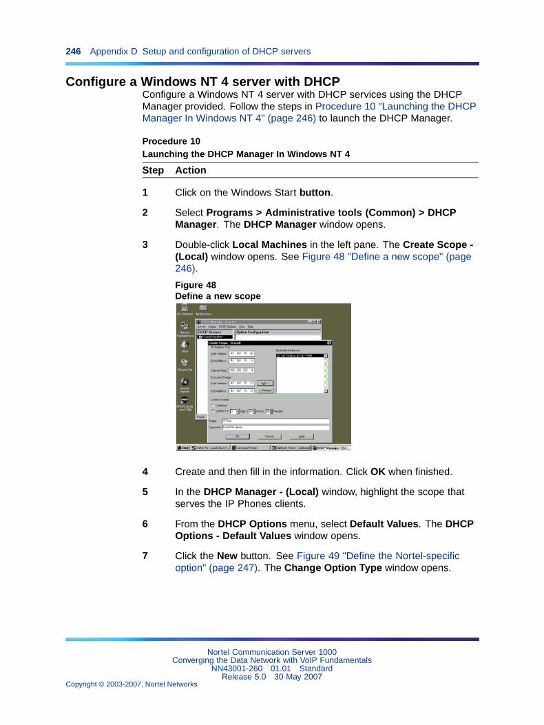
246 Appendix D Setup and configuration of DHCP servers
Configure a Windows NT 4 server with DHCPConfigure a Windows NT 4 server with DHCP services using the DHCPManager provided. Follow the steps in Procedure 10 "Launching the DHCPManager In Windows NT 4" (page 246) to launch the DHCP Manager.
Procedure 10Launching the DHCP Manager In Windows NT 4
Step Action
1 Click on the Windows Start button.
2 Select Programs > Administrative tools (Common) > DHCPManager. The DHCP Manager window opens.
3 Double-click Local Machines in the left pane. The Create Scope -(Local) window opens. See Figure 48 "Define a new scope" (page246).
Figure 48Define a new scope
4 Create and then fill in the information. Click OK when finished.
5 In the DHCP Manager - (Local) window, highlight the scope thatserves the IP Phones clients.
6 From the DHCP Options menu, select Default Values. The DHCPOptions - Default Values window opens.
7 Click the New button. See Figure 49 "Define the Nortel-specificoption" (page 247). The Change Option Type window opens.
Nortel Communication Server 1000Converging the Data Network with VoIP Fundamentals
NN43001-260 01.01 StandardRelease 5.0 30 May 2007
Copyright © 2003-2007, Nortel Networks
.
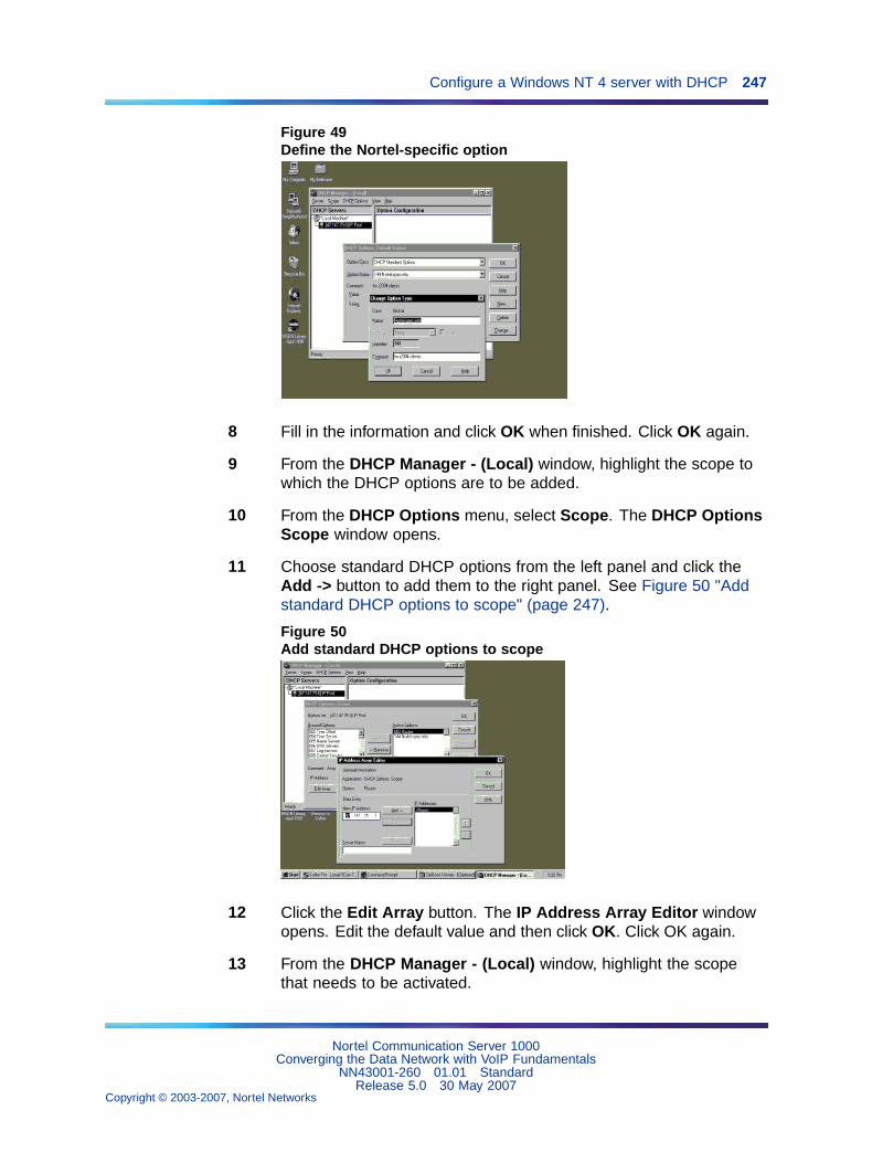
Configure a Windows NT 4 server with DHCP 247
Figure 49Define the Nortel-specific option
8 Fill in the information and click OK when finished. Click OK again.
9 From the DHCP Manager - (Local) window, highlight the scope towhich the DHCP options are to be added.
10 From the DHCP Options menu, select Scope. The DHCP OptionsScope window opens.
11 Choose standard DHCP options from the left panel and click theAdd -> button to add them to the right panel. See Figure 50 "Addstandard DHCP options to scope" (page 247).
Figure 50Add standard DHCP options to scope
12 Click the Edit Array button. The IP Address Array Editor windowopens. Edit the default value and then click OK. Click OK again.
13 From the DHCP Manager - (Local) window, highlight the scopethat needs to be activated.
Nortel Communication Server 1000Converging the Data Network with VoIP Fundamentals
NN43001-260 01.01 StandardRelease 5.0 30 May 2007
Copyright © 2003-2007, Nortel Networks
.
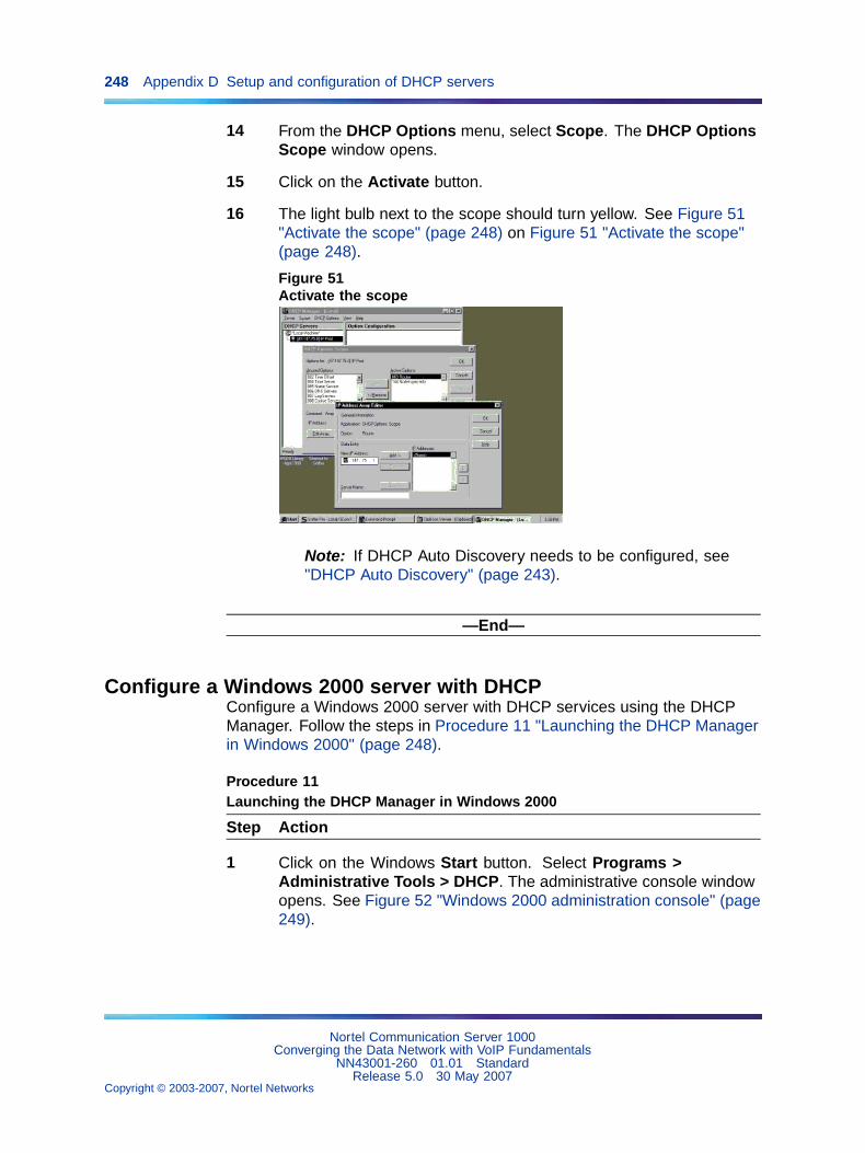
248 Appendix D Setup and configuration of DHCP servers
14 From the DHCP Options menu, select Scope. The DHCP OptionsScope window opens.
15 Click on the Activate button.
16 The light bulb next to the scope should turn yellow. See Figure 51"Activate the scope" (page 248) on Figure 51 "Activate the scope"(page 248).
Figure 51Activate the scope
Note: If DHCP Auto Discovery needs to be configured, see"DHCP Auto Discovery" (page 243).
—End—
Configure a Windows 2000 server with DHCPConfigure a Windows 2000 server with DHCP services using the DHCPManager. Follow the steps in Procedure 11 "Launching the DHCP Managerin Windows 2000" (page 248).
Procedure 11Launching the DHCP Manager in Windows 2000
Step Action
1 Click on the Windows Start button. Select Programs >Administrative Tools > DHCP. The administrative console windowopens. See Figure 52 "Windows 2000 administration console" (page249).
Nortel Communication Server 1000Converging the Data Network with VoIP Fundamentals
NN43001-260 01.01 StandardRelease 5.0 30 May 2007
Copyright © 2003-2007, Nortel Networks
.
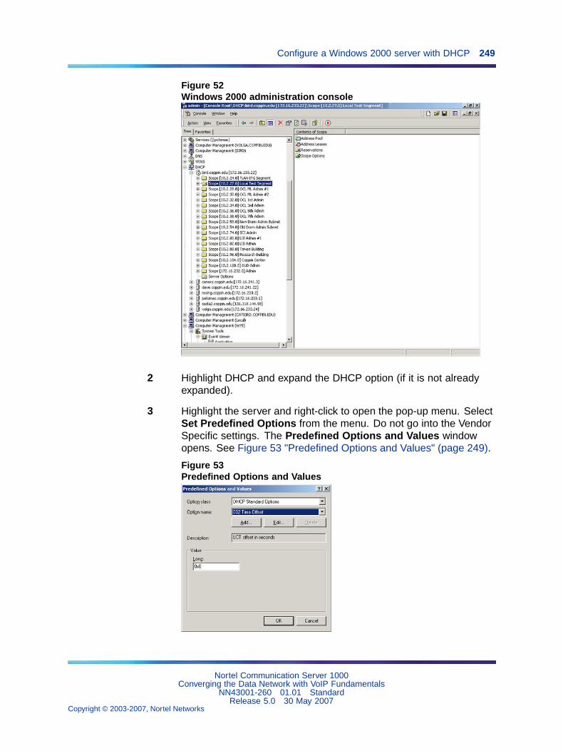
Configure a Windows 2000 server with DHCP 249
Figure 52Windows 2000 administration console
2 Highlight DHCP and expand the DHCP option (if it is not alreadyexpanded).
3 Highlight the server and right-click to open the pop-up menu. SelectSet Predefined Options from the menu. Do not go into the VendorSpecific settings. The Predefined Options and Values windowopens. See Figure 53 "Predefined Options and Values" (page 249).
Figure 53Predefined Options and Values
Nortel Communication Server 1000Converging the Data Network with VoIP Fundamentals
NN43001-260 01.01 StandardRelease 5.0 30 May 2007
Copyright © 2003-2007, Nortel Networks
.
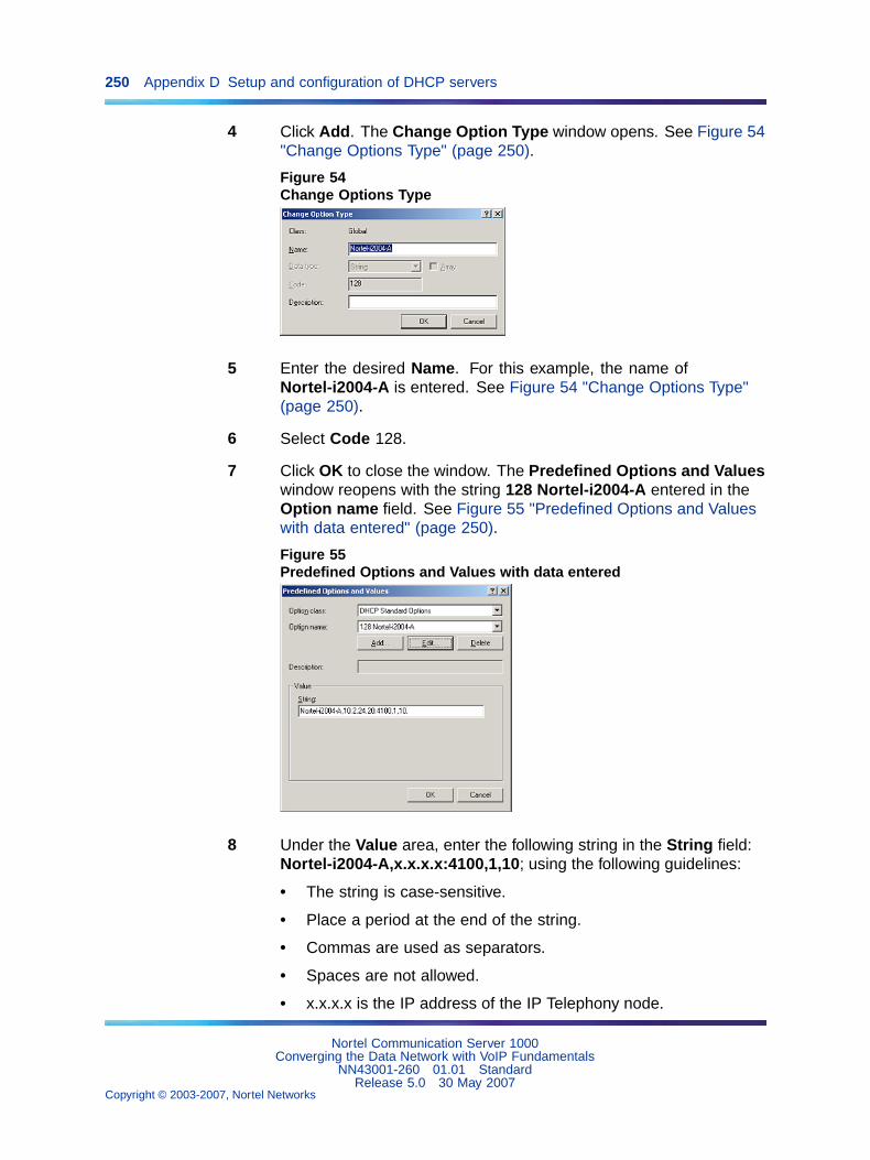
250 Appendix D Setup and configuration of DHCP servers
4 Click Add. The Change Option Type window opens. See Figure 54"Change Options Type" (page 250).
Figure 54Change Options Type
5 Enter the desired Name. For this example, the name ofNortel-i2004-A is entered. See Figure 54 "Change Options Type"(page 250).
6 Select Code 128.
7 Click OK to close the window. The Predefined Options and Valueswindow reopens with the string 128 Nortel-i2004-A entered in theOption name field. See Figure 55 "Predefined Options and Valueswith data entered" (page 250).
Figure 55Predefined Options and Values with data entered
8 Under the Value area, enter the following string in the String field:Nortel-i2004-A,x.x.x.x:4100,1,10; using the following guidelines:
• The string is case-sensitive.
• Place a period at the end of the string.
• Commas are used as separators.
• Spaces are not allowed.
• x.x.x.x is the IP address of the IP Telephony node.
Nortel Communication Server 1000Converging the Data Network with VoIP Fundamentals
NN43001-260 01.01 StandardRelease 5.0 30 May 2007
Copyright © 2003-2007, Nortel Networks
.
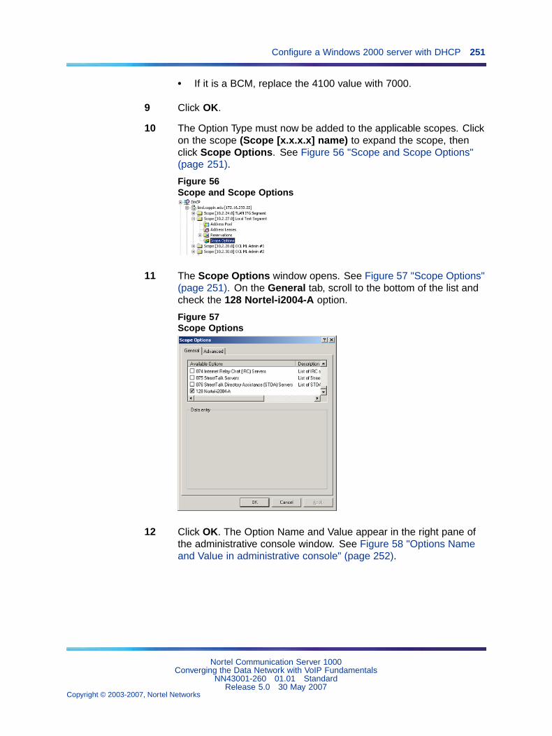
Configure a Windows 2000 server with DHCP 251
• If it is a BCM, replace the 4100 value with 7000.
9 Click OK.
10 The Option Type must now be added to the applicable scopes. Clickon the scope (Scope [x.x.x.x] name) to expand the scope, thenclick Scope Options. See Figure 56 "Scope and Scope Options"(page 251).
Figure 56Scope and Scope Options
11 The Scope Options window opens. See Figure 57 "Scope Options"(page 251). On the General tab, scroll to the bottom of the list andcheck the 128 Nortel-i2004-A option.
Figure 57Scope Options
12 Click OK. The Option Name and Value appear in the right pane ofthe administrative console window. See Figure 58 "Options Nameand Value in administrative console" (page 252).
Nortel Communication Server 1000Converging the Data Network with VoIP Fundamentals
NN43001-260 01.01 StandardRelease 5.0 30 May 2007
Copyright © 2003-2007, Nortel Networks
.
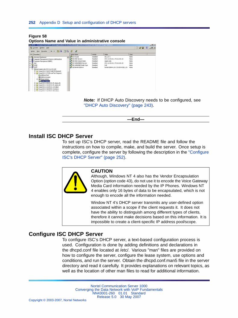
252 Appendix D Setup and configuration of DHCP servers
Figure 58Options Name and Value in administrative console
Note: If DHCP Auto Discovery needs to be configured, see"DHCP Auto Discovery" (page 243).
—End—
Install ISC DHCP ServerTo set up ISC’s DHCP server, read the README file and follow theinstructions on how to compile, make, and build the server. Once setup iscomplete, configure the server by following the description in the "ConfigureISC's DHCP Server" (page 252).
CAUTIONAlthough, Windows NT 4 also has the Vendor EncapsulationOption (option code 43), do not use it to encode the Voice GatewayMedia Card information needed by the IP Phones. Windows NT4 enables only 16 bytes of data to be encapsulated, which is notenough to encode all the information needed.
Window NT 4’s DHCP server transmits any user-defined optionassociated within a scope if the client requests it. It does nothave the ability to distinguish among different types of clients,therefore it cannot make decisions based on this information. It isimpossible to create a client-specific IP address pool/scope.
Configure ISC DHCP ServerTo configure ISC’s DHCP server, a text-based configuration process isused. Configuration is done by adding definitions and declarations inthe dhcpd.conf file located at /etc/. Various "man" files are provided onhow to configure the server, configure the lease system, use options andconditions, and run the server. Obtain the dhcpd.conf.man5 file in the serverdirectory and read it carefully. It provides explanations on relevant topics, aswell as the location of other man files to read for additional information.
Nortel Communication Server 1000Converging the Data Network with VoIP Fundamentals
NN43001-260 01.01 StandardRelease 5.0 30 May 2007
Copyright © 2003-2007, Nortel Networks
.
Configure ISC DHCP Server 253
Configure ISC DHCP to work with the IP PhonesFollow the steps in Procedure 12 "Configuring ISC's DHCP server" (page253) to configure the ISC’s DHCP to work with the IP Phones.
There is a particular format for encoding the Voice Gateway Media Cardinformation. In addition to the configuration statements provided, othernetwork and subnet declarations must also be included in the configurationfile.
As indicated in the beginning of this section, read the man files and use"Example 1: Configuration file" (page 254) on to configure ISC’s DHCPserver to work with the IP Phones. Also, a copy of the configuration file usedfor this project is provided at the end of this section.
Procedure 12Configuring ISC DHCP server
Step Action
1 Configure the server to identify a client correctly as an IP Phone2001, IP Phone 2002, IP Phone 2004, or IP Phone 2007. This isdone using a match statement with a conditional if enclosed insidea class declaration, as follows:
class "i2004-clients"{match if option vendor-class-identifier =4e:6f:72:74:65:6c:2d:69:32:30:30:34:2d:41:00;}
The Hex string represents the text string "Nortel-i2004-A". If thevendor-class-identifier obtained from the client’s DHCPDISCOVERmessage match this Hex-encoded string, then the server adds thisclient to the "i2004-clients" class. Once a client is classified as amember of a class, it must follow the rules of the class.
2 Declare a pool of IP addresses exclusively for the members of the"i2004-clients" class. The pool declaration is used to group a rangeof IP addresses together with options and parameters that applyonly to the pool.
3 Restrict access to the pool. Use the allow or deny statementto include or exclude the members of a particular class. Forexample, the follow configuration code enables only members of"i2004-clients" to use this IP address pool:
pool{allow members of "i2004-clients";
range 47.147.75.60 47.147.75.65;option routers 47.147.75.1;
# Nortel special stringoption vendor-encapsulated-options80:3d:4e:6f:72:É;}
Nortel Communication Server 1000Converging the Data Network with VoIP Fundamentals
NN43001-260 01.01 StandardRelease 5.0 30 May 2007
Copyright © 2003-2007, Nortel Networks
.
254 Appendix D Setup and configuration of DHCP servers
Note: If a client is not a member of this class, it is not assignedan IP address from this pool, even if there were no other availableIP addresses.
4 The DHCPOFFER from the ISC server must include the VoiceGateway Media Card information if the client is an IP Phone 2001,IP Phone 2002, IP Phone 2004, or IP Phone 2007. There are twomethods to encode the necessary information for the IP Phone2004 client:
a. Use the vendor-encapsulated-options option (as in theprevious example) to encode the information as a sub option.
b. Define a Site Specific option to carry the necessary information.To define a site specific option:
• give a declaration in the form of the name of the option, theoption code, and the type of data it carries outside any poolor network declarations. For example:
option Nortel-specific-info code 144 = string;
• replace the vendor-encapsulated option inside the poolstatement with the definition,
option Nortel-specific-info = "Nortel É";
Note: If DHCP Auto Discovery needs to be configured, see"DHCP Auto Discovery" (page 243).
—End—
Example 1: Configuration fileThe following format must be used for encoding the Voice Gateway MediaCard information. In addition to the configuration statements provided, othernetwork and subnet declarations must also be included in the configurationfile. As mentioned in the beginning of this section, read the man files anduse the following example as a guideline:
# File name: dhcpd.conf# Location: /etc/# Description: Configuration file for ISC dhcpd server# Author: Cecilia Mok# Date: September 24, 1999
# Global option definitions common for all supported# networks...default-lease-time 300;max-lease-time 7200;option subnet-mask 255.255.255.0;option broadcast-address 255.255.255.255;
Nortel Communication Server 1000Converging the Data Network with VoIP Fundamentals
NN43001-260 01.01 StandardRelease 5.0 30 May 2007
Copyright © 2003-2007, Nortel Networks
.
Configure ISC DHCP Server 255
# Defining Nortel-specific option for IP Phone 2004 clientoption my-vendor-specific-info code 144 = string;# Declaring a class for IP Phones type 2002, 2004, and 2007# clients.
# Add new clients to the class if their Class Identifier# match the special IP Phone 2004 ID string.class "i2004-clients"
{match if option vendor-class-identifier =
4e:6f:72:74:65:6c:2d:69:32:30:30:34:2d:41:00;}
# Declaring another class for PC clientsclass "pc-clients"{}
# Declaring a shared network# This is to accommodate two different subnets on the same# physical network; see dhcpd.conf.man5 for more detailsshared-network "myNetwork"{
# Declaring subnet for current serversubnet 47.147.77.0 netmask 255.255.255.0{}
# Declaring subnet for DHCP clientssubnet 47.147.75.0 netmask 255.255.255.0{# Pool addresses for i2004 clientspool{allow members of "i2004-clients";
range 47.147.75.60 47.147.75.65;option routers 47.147.75.1;# Nortel special string
option Nortel-specific-info = "NortelÉ";}
default-lease-time 180;max-lease-time 300;
}
Finally, before starting the server, create a blank dhcpd.leases file in the/etc/ directory, which is the same location as the dhcpd.conf file. To start theserver, go to /var/usr/sbin/ and type:
./dhcpd
To run in debug mode, type:
./dhcpd –d –f
Nortel Communication Server 1000Converging the Data Network with VoIP Fundamentals
NN43001-260 01.01 StandardRelease 5.0 30 May 2007
Copyright © 2003-2007, Nortel Networks
.
256 Appendix D Setup and configuration of DHCP servers
Install and configure a Solaris 2 serverInstall a Solaris 2 Server
To set up the Solaris 2 server, consult the accompanying manual and onlinedocumentation.
Configure a Solaris 2 serverFollow the steps in Procedure 13 "Configuring a Solaris 2 server" (page256) to configure Solaris 2 with DHCP.
Procedure 13Configuring a Solaris 2 server
Step Action
1 Read the following man pages:
• dhcpconfig
• dhcptab
• in.dhcpd
Note: There are also directions at the end of each page referringto other sources that are helpful.
2 Collect information about the network such as subnet mask,router/Media Gateway and DNS server IP addresses as specified.Make sure this information is current.
3 Log on as root and invoke the interface by typing dhcpconfig atthe prompt. A list of questions is presented and the administratormust supply answers that are then used to configure the DHCPserver.
Note 1: Solaris 2 uses a text-based interface for configuringDHCP services.
Note 2: If DHCP Auto Discovery needs to be configured, see"DHCP Auto Discovery" (page 243).
—End—
Procedure 14Configuring Solaris 2 to work with IP Phones
Step Action
1 Do one of the following:
Nortel Communication Server 1000Converging the Data Network with VoIP Fundamentals
NN43001-260 01.01 StandardRelease 5.0 30 May 2007
Copyright © 2003-2007, Nortel Networks
.
Install and configure a Solaris 2 server 257
• Create a symbol definition for defining a Site Specific option bytyping the following in the dhcptab configuration table located at/etc/default/dhcp:
NI2004 s Site,128,ASCII,1,0
• Use the dhtadm configuration table management utility by typingthe following command at the prompt:
dhtadm -A -s NI2004 –d ’Site,128,ASCII,1,0’
Where:
NI2004:symbol names:identify definition as symbolSite:site specific option128:option codeASCII:data type1:granularity0:no maximum size of granularity, that is, infinite
2 Create a Client Identifier macro by doing one of the following:
• entering the following:
Nortel-i2004-A m:NI2004="NortelÉ":
• Use the dhtadm command:
dhtadm -A -m Nortel-i2004-A -d’:NI2004="NortelÉ":’
3 Invoke the DHCP services on the Solaris server by entering at theprompt.:
in.dhcpd,
Specify –d and/or –v options for debug mode. See man pagein.dhpcd for more details.
—End—
An example of the tables used in this project is as follows:
DhcptabTable
Locale m :UTCoffst=18000:
nbvws286 m
:Include=Locale:LeaseTim=150:LeaseNeg:DNSdmain=ca.nortel.com:/
DNSserv=47.108.128.216 47.211.192.8 47.80.12.69:
Nortel Communication Server 1000Converging the Data Network with VoIP Fundamentals
NN43001-260 01.01 StandardRelease 5.0 30 May 2007
Copyright © 2003-2007, Nortel Networks
.
258 Appendix D Setup and configuration of DHCP servers
47.147.75.0 m :NISdmain=bvwlab:NISservs=47.147.64.91:
47.147.64.0 m
:Broadcst=47.147.79.255:Subnet=255.255.240.0:MTU=1500:/
Router=47.147.64.1:NISdmain=bvwlab:NISservs=47.147.64.91:
#
NI2004 s Site,128,ASCII,1,0
Nortel-i2004-A m:
NI2004="Nortel-i2004-A,47.147.75.31:4100,1,5;47.147.77.143:4100,1,5.":
Network Table
01006038760290 00 47.147.65.198 47.147.74.36 944600968
nbvws286
0100C04F662B6F 00 47.147.65.199 47.147.74.36 944600959 nbvws286
Nortel Communication Server 1000Converging the Data Network with VoIP Fundamentals
NN43001-260 01.01 StandardRelease 5.0 30 May 2007
Copyright © 2003-2007, Nortel Networks
.
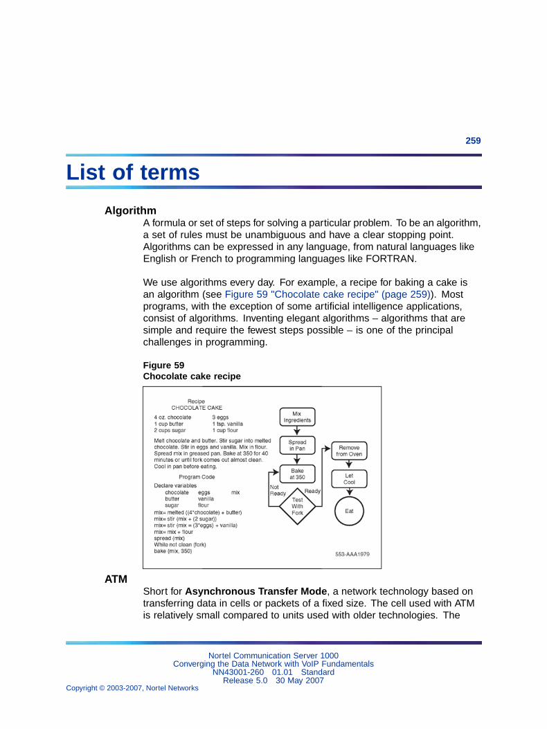
259
List of terms
AlgorithmA formula or set of steps for solving a particular problem. To be an algorithm,a set of rules must be unambiguous and have a clear stopping point.Algorithms can be expressed in any language, from natural languages likeEnglish or French to programming languages like FORTRAN.
We use algorithms every day. For example, a recipe for baking a cake isan algorithm (see Figure 59 "Chocolate cake recipe" (page 259)). Mostprograms, with the exception of some artificial intelligence applications,consist of algorithms. Inventing elegant algorithms – algorithms that aresimple and require the fewest steps possible – is one of the principalchallenges in programming.
Figure 59Chocolate cake recipe
ATMShort for Asynchronous Transfer Mode, a network technology based ontransferring data in cells or packets of a fixed size. The cell used with ATMis relatively small compared to units used with older technologies. The
Nortel Communication Server 1000Converging the Data Network with VoIP Fundamentals
NN43001-260 01.01 StandardRelease 5.0 30 May 2007
Copyright © 2003-2007, Nortel Networks
.
260 List of terms
small, constant cell size allows ATM equipment to transmit video, audio,and computer data over the same network, and assure that no single typeof data hogs the line.
Current implementations of ATM support data transfer rates of from 25 to622 Mbps (megabits per second). This compares to a maximum of 100Mbps for Ethernet, the current technology used for most LANs.
Some people think that ATM holds the answer to the Internet bandwidthproblem, but others are skeptical. ATM creates a fixed channel, or route,between two points whenever data transfer begins. This differs from TCP/IP,in which messages are divided into packets and each packet can take adifferent route from source to destination. This difference makes it easierto track and bill data usage across an ATM network, but it makes it lessadaptable to sudden surges in network traffic.
When purchasing ATM service, there generally is a choice of four differenttypes of service:
• Constant Bit Rate (CBR) specifies a fixed bit rate so that data is sent ata constant rate. This is analogous to a leased line.
• Variable Bit Rate (VBR) provides a specified throughput capacity butdata is not sent evenly. This is a popular choice for voice and videoconferencing data.
• Unspecified Bit Rate (UBR) does not guarantee any throughput levels.This is used for applications, such as file transfer, that can toleratedelays.
• Available Bit Rate (ABR) provides a guaranteed minimum capacity butallows data to be bursted at higher capacities when the network is free.
CBRConstant Bit Rate. See ATM.
CIRCommitted Information Rate. A Frame relay term. CIR is the level of datatraffic in bits that a carrier agrees to handle – not at all times, but averagedover a period of time.
ClientThe client part of a client-server architecture. Typically, a client is anapplication that runs on a personal computer or workstation and relies ona server to perform some operations. For example, an e-mail client is anapplication that enables a user to send and receive e-mail.
Nortel Communication Server 1000Converging the Data Network with VoIP Fundamentals
NN43001-260 01.01 StandardRelease 5.0 30 May 2007
Copyright © 2003-2007, Nortel Networks
.
List of terms 261
COPS-PRCommon Open Policy Service (COPS) is an IETF standard (RFC 2748).It provides a standard protocol for exchange of policy information betweennetwork servers, and network clients such as routers and switches.COPS-PR (COPS Usage for Policy Provisioning) is a provisioning layerdesigned to facilitate the implementation of new policies, as defined byPolicy Information Bases (PIBs).
Network administrators can quickly deploy new services and configurationsacross a network, using the COPS-PR layer, to dynamically update networkdevices with new policies. It provides the necessary services to propagateDiffServ policy information across the network.
DiffServDifferentiated Services. DiffServ specifies, on a per-packet basis, how IPtraffic is handled. The handling is specified based on the packet’s DiffServCodePoint (DSCP). A method for adding Quality of Service (QoS) to IPnetworks from the IETF, DiffServ is the preferred Layer 3 QoS mechanismfor CS 1000 Release 4.5.
Operating at Layer 3 only, Diffserv uses the IP Type Of Service (TOS) fieldas the Diffserv byte (DS byte).
DiffServ domainA network segment that is DiffServ-aware.
DiffServ edgeWhere the DiffServ domain begins. Defined in the DiffServ ArchitectureRFC 2475.
DiffServ Edge NodeThe first Layer 3-aware device that a packet encounters.
DSCPDiffServ CodePoint. Six bits in an IP packet header that specify how apacket is to be handled on an IP network.
DSPDigital Signal Processing, which refers to manipulating analog information,such as sound or photographs that has been converted into a digital form.DSP also implies the use of a data compression technique.
Nortel Communication Server 1000Converging the Data Network with VoIP Fundamentals
NN43001-260 01.01 StandardRelease 5.0 30 May 2007
Copyright © 2003-2007, Nortel Networks
.
262 List of terms
When used as a noun, DSP stands for Digital Signal Processor, a specialtype of coprocessor designed for performing the mathematics involved inDSP. Most DSPs are programmable, which means that they can be usedfor manipulating different types of information, including sound, images,and video.
Full-duplexTransmission in both directions at the same time can occur on thebandwidth. The full bandwidth of the link is available in either direction.
GatewayIn networking, a combination of hardware and software that links twodifferent types of networks. Gateways between e-mail systems, for example,allow users on different e-mail systems to exchange messages.
H.323A standard approved by the International Telecommunication Union (ITU)that defines how audiovisual conferencing data is transmitted acrossnetworks. In theory, H.323 should enable users to participate in thesame conference even though they are using different video conferencingapplications. Although most video conferencing vendors have announcedthat their products will conform to H.323, it’s too early to say whether suchadherence will actually result in interoperability.
Half-duplexPackets are transmitted in only one direction at a time. The send and receivebandwidth is shared. Packet collisions can occur on half-duplex links.
IEEE 802 standards
IEEE
Institute of Electrical and Electronics Engineers, pronounced I-triple-E.Founded in 1884 as the AIEE, the IEEE was formed in 1963 whenAIEE merged with IRE. IEEE is an organization composed of engineers,scientists, and students. The IEEE is best known for developingstandards for the computer and electronics industry. In particular, theIEEE 802 standards for local-area networks are widely followed.
802 standards
Nortel Communication Server 1000Converging the Data Network with VoIP Fundamentals
NN43001-260 01.01 StandardRelease 5.0 30 May 2007
Copyright © 2003-2007, Nortel Networks
.
List of terms 263
A set of network standards developed by the IEEE. They include:
• IEEE 802.1: Standards related to network management.
• IEEE 802.2: General standard for the data link layer in the OSIReference Model. The IEEE divides this layer into two sublayers-- the logical link control (LLC) layer and the media access control(MAC) layer. The MAC layer varies for different network types and isdefined by standards IEEE 802.3 through IEEE 802.5.
• IEEE 802.3: Defines the MAC layer for bus networks that useCSMA/CD. This is the basis of the Ethernet standard.
• IEEE 802.4: Defines the MAC layer for bus networks that use atoken-passing mechanism (token bus networks).
• IEEE 802.5: Defines the MAC layer for token-ring networks.
• IEEE 802.6: Standard for Metropolitan Area Networks (MANs).
IEEE 802.1: network management
Refers to the broad subject of managing computer networks. Thereexists a wide variety of software and hardware products that help networksystem administrators manage a network. Network management coversa wide area, including:
• Security: Ensuring that the network is protected from unauthorizedusers.
• Performance: Eliminating bottlenecks in the network.
• Reliability: Making sure the network is available to users andresponding to hardware and software malfunctions.
IEEE 802.1p
The Class of Service bits within an IEEE 802.1Q VLAN tag.
IEEE 802.1Q
The IEEE specification referring to Virtual Local Area Networks (VLANs).It includes "Class of Service" and VLAN ID.
IEEE 802.2: MAC Layer
The Media Access Control Layer is one of two sublayers that make upthe Data Link Layer of the OSI model. The MAC layer is responsible formoving data packets to and from one Network Interface Card (NIC) toanother across a shared channel.
See a breakdown of the seven OSI layers in the Quick Reference sectionof Webopedia.
Nortel Communication Server 1000Converging the Data Network with VoIP Fundamentals
NN43001-260 01.01 StandardRelease 5.0 30 May 2007
Copyright © 2003-2007, Nortel Networks
.
264 List of terms
The MAC sublayer uses MAC protocols to ensure that signals sent fromdifferent stations across the same channel don’t collide.
Different protocols are used for different shared networks, such asEthernet, Token Ring, and Token Bus.
IPAbbreviation of Internet Protocol, pronounced as two separate letters. IPspecifies the format of packets, also called datagrams, and the addressingscheme. Most networks combine IP with a higher-level protocol calledTransport Control Protocol (TCP), which establishes a virtual connectionbetween a destination and a source.
IP by itself is something like the postal system. It allows you to address apackage and drop it in the system, but there’s no direct link between youand the recipient. TCP/IP, on the other hand, establishes a connectionbetween two hosts so that they can send messages back and forth fora period of time.
The current version of IP is IPv4. A new version, called IPv6 or IPng, isunder development.
IPSecA group of IP security measures. It defines privacy, integrity, authentication,security key management, and tunnelling methods. A secure versionof IP, IPSec enables a secure VPN over the Internet, providing optionalauthentication and encryption at the packet level.
Layer 2 switchingPackets are forwarded based on the destination’s MAC address. Theswitch automatically determines which switch port must be used to sendthe packet, based on the destination’s MAC address. The MAC addresslocation was determined from incoming packets from that MAC addressreceived on that port.
Layer 3 switchingPacket traffic is grouped based on source and destination addresses. Thefirst packet in a flow is routed by a software-based algorithm. Subsequentpackets with the same source and destination addresses are switchedbased on the destination’s MAC address (hardware mechanism). This issimilar to multi-layer routing and routers with hardware assist.
Nortel Communication Server 1000Converging the Data Network with VoIP Fundamentals
NN43001-260 01.01 StandardRelease 5.0 30 May 2007
Copyright © 2003-2007, Nortel Networks
.
List of terms 265
MIBManagement Information Base. A database of network performanceinformation that is stored on a Network Agent. It contains characteristicsand parameters about network devices such as NICs, hubs, switches, androuters. This information is accessed by software like SNMP.
MIDMessage Identifier.
MUAMail User Agent. The mail program used by an end-user computer to createand read e-mail messages.
NATNetwork Address Translation. It is defined as an Internet standard thatlets a LAN use both internal and external IP addresses. This protects aninternal IP address from being accessed from outside. NAT translates theinternal IP addresses to unique IP addresses before sending out packets.NAT is practical when only a few users in a domain need to communicateoutside of the domain at the same time.
Object IdentifierAlso known as OID. An object is identified as a numeric value thatrepresents some aspect of a managed device. An Object Identifier (OID) isa sequence of numbers, separated by periods, which uniquely defines theobject within an MIB.
OIDSee Object Identifier.
PolicyA set of rules defining how certain network traffic should be treated. Therules consist of classification, marking, and queueing specifications.
Proxy ServerA server that sits between a client application, such as a web browser, anda real server. It intercepts all requests to the real server to see if it can fulfillthe requests itself. If not, it forwards the request to the real server.
Proxy servers have two main purposes:
• Improve Performance: Proxy servers can dramatically improveperformance for groups of users. This is because it saves the resultsof all requests for a certain amount of time. Consider the case whereboth user X and user Y access the World Wide Web through a proxyserver. First user X requests a certain webpage, which we’ll call Page 1.Sometime later, user Y requests the same page. Instead of forwarding
Nortel Communication Server 1000Converging the Data Network with VoIP Fundamentals
NN43001-260 01.01 StandardRelease 5.0 30 May 2007
Copyright © 2003-2007, Nortel Networks
.
266 List of terms
the request to the web server where Page 1 resides, which can be atime-consuming operation, the proxy server simply returns the Page 1that it already fetched for user X. Since the proxy server is often on thesame network as the user, this is a much faster operation. Real proxyservers support hundreds or thousands of users. The major onlineservices such as Compuserve and America Online, for example, employan array of proxy servers.
• Filter Requests: Proxy servers can also be used to filter requests. Forexample, a company might use a proxy server to prevent its employeesfrom accessing a specific set of websites.
PSTNShort for Public Switched Telephone Network, which refers to theinternational telephone system based on copper wires carrying analogvoice data. This is in contrast to newer telephone networks base on digitaltechnologies, such as ISDN and FDDI.
Telephone service carried by the PSTN is often called plain old telephoneservice (POTS).
PVCPermanent Virtual Circuit. All transmitted data between two points follows apre-determined path.
QoSQuality of Service. A networking term that specifies a guaranteedthroughput level. One of the biggest advantages of ATM over competingtechnologies such as Frame Relay and Fast Ethernet, is that it supportsQoS levels. This allows ATM providers to guarantee to their customers thatend-to-end delay does not exceed a specified level.
RMONRemote Monitoring specification. It is a set of SNMP-based MIBs(Management Information Bases) that define the monitoring, instrumenting,and diagnosis of LANS. It occurs at OSI Layer 2 (DLL). RMON-2 monitorsabove Layer 2, and can see across segments and through routers. See'SNMP' on page 322.
routingThe process of selecting the correct path for packets transmitted between IPnetworks by using software-based algorithms. Each packet is processed bythe algorithm to determine its destination.
Nortel Communication Server 1000Converging the Data Network with VoIP Fundamentals
NN43001-260 01.01 StandardRelease 5.0 30 May 2007
Copyright © 2003-2007, Nortel Networks
.
List of terms 267
RTPReal-time Transport Protocol. An IETF standard that supports transport ofreal-time data, like voice and video, over packet switched networks. It doesnot provide QoS control.
ServerA computer or device on a network that manages network resources. Forexample, a file server is a computer and storage device dedicated to storingfiles. Any user on the network can store files on the server. A print server isa computer that manages one or more printers, and a network server is acomputer that manages network traffic. A database server is a computersystem that processes database queries.
Servers are often dedicated, meaning that they perform no other tasksbesides their server tasks. On multiprocessing operating systems, however,a single computer can execute several programs at once. A server in thiscase could refer to the program that is managing resources rather thanthe entire computer.
Shared-media hubA central connecting device in a network that joins communication linestogether in a star configuration. Packets received on a shared-media hubare transmitted out of all other ports on the hub. This means all links mustbe half-duplex.
SNMPSimple Network Management Protocol. A set of protocols for managingcomplex networks. The first versions of SNMP were developed in the early1980s. SNMP works by sending messages, called Protocol Data Units(PDUs), to different parts of a network. SNMP-compliant devices, calledagents, store data about themselves in Management Information Bases(MIBs) and return this data to the SNMP requesters.
SNMP 1 reports only whether a device is functioning properly. The industryhas attempted to define a new set of protocols called SNMP 2 that wouldprovide additional information, but the standardization efforts have not beensuccessful. Instead, network managers have turned to a related technologycalled RMON that provides more detailed information about network usage.
SubnetSubnetwork. A segment of an IP network. Packets must be routed in andout of a subnet.
Nortel Communication Server 1000Converging the Data Network with VoIP Fundamentals
NN43001-260 01.01 StandardRelease 5.0 30 May 2007
Copyright © 2003-2007, Nortel Networks
.
268 List of terms
TDMTime Division Multiplexing, a type of multiplexing that combines data streamsby assigning each stream a different time slot in a set. TDM repeatedlytransmits a fixed sequence of time slots over a single transmission channel.
Within T-Carrier systems, such as T-1 and T-3, TDM combines Pulse CodeModulated (PCM) streams created for each conversation or data stream.
UDPUser Datagram Protocol. Part of the TCP/IP protocol suite. It allows for theexchange of datagrams without acknowledgement or guarantee of delivery.UDP is at Layer 4 of the OSI model.
VLANVirtual LAN. A logical grouping of network devices, located on differentphysical LAN segments, into a single domain. This allows the devices tointerwork as though they were on the same segment.
WANWide Area Network. A computer network that spans a relatively largegeographical area. Typically, a WAN consists of two or more local-areanetworks (LANs).
Computers connected to a wide-area network are often connected throughpublic networks, such as the telephone system. They can also be connectedthrough leased lines or satellites. The largest WAN in existence is theInternet.
Nortel Communication Server 1000Converging the Data Network with VoIP Fundamentals
NN43001-260 01.01 StandardRelease 5.0 30 May 2007
Copyright © 2003-2007, Nortel Networks
.

Nortel Communication Server 1000
Converging the Data Network with VoIP FundamentalsCopyright © 2003-2007, Nortel NetworksAll Rights Reserved.
Publication: NN43001-260Document status: StandardDocument version: 01.01Document date: 30 May 2007
To provide feedback or report a problem in the document, go to www.nortel.com/documentfeedback.
Sourced in Canada.
The information in this document is subject to change without notice. The statements, configurations, technical data, andrecommendations in this document are believed to be accurate and reliable, but are presented without express or impliedwarranty. Users must take full responsibility for their applications of any products specified in this document. The information inthis document is proprietary to Nortel Networks.
Nortel, the Nortel Logo, the Globemark, SL-1, Meridian1, and Succession are trademarks of Nortel Networks.All other trademarks are the property of their respective owners.