conversion between hungarian map projection …
TRANSCRIPT

CONVERSION BETWEEN HUNGARIAN MAP PROJECTION SYSTEMS
VETULET+ Version 7.22 Copyright (c) 1988-2005. (Dr.L.Völgyesi, BME. H-1521 Budapest)
Made by: Dr.Lajos Völgyesi, Dr.Gyula Tóth, Dr.József Varga Technical University of Budapest, Dept.of Geodesy Budapesti Műszaki Egyetem, Felsőgeodézia Tanszék 1111. Budapest, Műegyetem rkp. 3. (K.I.61) 463-3223 , fax: 463-3192 E-mail: VOLGYESI@ EIK.BME.HU
Budapest, March 2005

2
The software MAPRO or MAPRO+ can be used for conversions between Hungarian geodetic map projections and their datum surfaces in the complete area of Hungary. The software has two versions: MAPRO is the basic version of conversions between map projection systems; MAPRO+ is the professional version which contains not only the base software MAPRO, but includes the program Mapol.exe to calculate coefficients of transformation polynomials required for map projection conversions. When different map projection systems are applied simultaneously over a given area the need of conversion permanently arises in the overlapping areas of these systems. Conversions, however, can not always be made by closed mathematical formulas and in these cases it frequently raises serious problems to apply a correct transformation method. Hence such algorithm and program package was developed for all combination conversion between Hungarian map projection systems and their reference surfaces which should not cause difficulties even for users having no deeper knowledge in map projections. This software can be used on IBM PC or compatible personal computers under MS DOS or any Windows operation sistems. There is a possibility of data input either from keyboard or a disk file. Output results can optionally be directed to the screen, printer or to a floppy or hard disk to a disk file. The first part of this description includes a short summary of basic knowledge about map projections which is necessary for using the programs. After this information needed to install program package can be read. Next part of the description contains instructions how to use map projection conversion program Mapro.exe, and finally the operation of Mapol.exe is discussed, which can be used to calculate coefficients of transformation polynomials required for map projection conversions.
MAP PROJECTION BASICS REQUIRED FOR THE USE OF PROGRAM PACKAGE
A multitude of map projection systems was resulted in Hungary because there were many subsequent (and mostly justified) changes in geodetic reference systems. Three different stereographic map projection systems were used for geodetic purposes and three conformal tangent cylindrical systems were required as well. Two zones of Gauss-Krüger and UTM projection cover over the area of the country thus more than one system is used even within a single kind of projection. Besides, the Unified National Projection system (EOV) was introduced in the whole area of Hungary as well. The former Hungarian Gaussian sphere, tangent to the Bessel ellipsoid is the common reference surface of Hungarian stereographic and conformal tangent cylindrical systems, the new Hungarian Gaussian sphere, tangent to the IUGG-67 ellipsoid, is the reference for EOV system and the Krassovsky ellipsoid is the reference surface for Gauss-Krüger projections in our country. Furthermore, WGS-84 ellipsoidal or geocentric Cartesian co-ordinates result from GPS measurements more recently and even it is required in international relations to use the UTM system in more recent times. This picture is complicated further on by the fact that besides the above mentioned systems also military stereographic, in the area of Budapest city stereographic and in some villages of the country even system without projection are used.

3
When different map projection systems are used simultaneously over the same area the need of conversion frequently arises inside overlapping areas. Circumstances are the same when there are different zones within a single projection (e.g. Gauss-Krüger or UTM projections), then inside the periphery of neighbouring zones co-ordinates are to be converted usually. More generally speaking: when the projection system of our maps differ from that of our control points available, our measurement results have to be transformed into the projection system of our map that they could be represented on it. Conversions may take place either by the so called co-ordinate method (with closed mathematical expressions) or through transformation equations (power series), which were provided by using so called common points that have known co-ordinates in both systems. It is possible to make exact conversions with closed mathematical expressions in cases only when both projection systems has the same reference surface and points of the same triangulation network coming from the same adjustment are represented in both projection systems. It is since if a point belonging to a different triangulation network is converted from one system into the other then transformed co-ordinates will not fit suitably into points of the triangulation network presented on the projection plane in question. It is true because one should consider differences that may arise from the different position and orientation of the two triangulation networks and also base extension networks and angle observations are quite different. A refinement of any triangulation network with recent measurements or with a readjustment alters co-ordinates of horizontal control points with respect to the reference surface and hence co-ordinate on the projection plane as well. The effects are the same when some parameters of the reference surface are modified even in that case when otherwise our triangulation network remains the same. Any re-orientation of the network (a rotation of the reference surface) does not hinder exact conversion. When the co-ordinate method is applied, conversion may be made by rigorous mathematical expressions found in some reference works enlisted. In each such cases when any of the above mentioned requirements has not been met the conversion is not possible by closed mathematical formulas. The conversion therefore can be performed only by transformation equations, which were deduced as power series from certain common points that have co-ordinates in both projection systems. In this case polynomials up to the maximum degree five can be applied and coefficients (altogether 42 coefficients) can be determined by using common points suitably through an adjustment process. In such a case slightly different co-ordinates will be resulted after the conversion process depending on the position and number of selected common points and the applied method. Since it may cause problems even for experts to apply correct methods of conversion between a multitude of map projection systems so we worked out such a program package by which conversions can be made between Hungarian map projection systems and their reference co-ordinates in all combination, the usage of which can cause no problem even for users having no deeper knowledge in map projections. Conversion between co-ordinates VTN = system without projection BES = Bessel's ellipsoidal co-ordinates SZT = Budapest stereographic projection KST = military stereographic projection HER = North cylindrical projection system HKR = middle cylindrical projection system
4
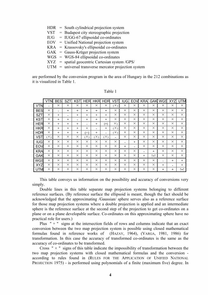
HDR = South cylindrical projection system VST = Budapest city stereographic projection IUG = IUGG-67 ellipsoidal co-ordinates EOV = Unified National projection system KRA = Krassovsky's ellipsoidal co-ordinates GAK = Gauss-Krüger projection system WGS = WGS-84 ellipsoidal co-ordinates XYZ = spatial geocentric Cartesian system /GPS/ UTM = universal transverse mercator projection system are performed by the conversion program in the area of Hungary in the 212 combinations as it is visualized in Table 1.
Table 1
VTN BES SZT KST HER HKR HDR VST IUG EOV KRA GAK WGS XYZ UTMVTN - ( ) BES - + + + + + SZT + - + + + + KST + + - + + + HER + + + - + (+) ) HKR + + + + - + ( ) HDR + + + (+) + - ( ) VST ( ) ( ) ( ) ( ) - IUG - + EOV + - KRA - + GAK + !+! WGS - + + XYZ + - + UTM + + !+!
This table conveys us information on the possibility and accuracy of conversions very simply. Double lines in this table separate map projection systems belonging to different reference surfaces. (By reference surface the ellipsoid is meant, though the fact should be acknowledged that the approximating /Gaussian/ sphere serves also as a reference surface for those map projection systems where a double projection is applied and an intermediate sphere is the reference surface at the second step of the projection to get co-ordinates on a plane or on a plane developable surface. Co-ordinates on this approximating sphere have no practical role for users.) Plus " + " signs at the intersection fields of rows and columns indicate that an exact conversion between the two map projection system is possible using closed mathematical formulas found in reference works of (HAZAY, 1964), (VARGA, 1981, 1986) for transformation. In this case the accuracy of transformed co-ordinates is the same as the accuracy of co-ordinates to be transformed. Cross " " signs of this table indicate the impossibility of transformation between the two map projection systems with closed mathematical formulas and the conversion - according to rules found in (RULES FOR THE APPLICATION OF UNIFIED NATIONAL PROJECTION 1975) - is performed using polynomials of a finite (maximum five) degree. In
5
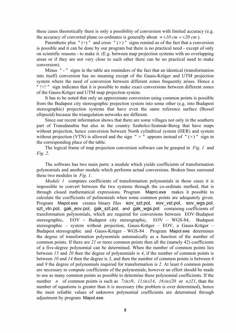
these cases theoretically there is only a possibility of conversion with limited accuracy (e.g. the accuracy of converted plane co-ordinates is generally about ≈ ±10 cm ÷ ±20 cm ). Parenthetic plus " (+) " and cross " ( ) " signs remind us of the fact that a conversion is possible and it can be done by our program but there is no practical need - except of only on scientific reasons - to make it. (E.g. between map projection systems with no overlapping areas or if they are not very close to each other there can be no practical need to make conversion). Minus " - " signs in the table are reminders of the fact that an identical (transformation into itself) conversion has no meaning except of the Gauss-Krüger and UTM projection system where the need of conversion between different zones frequently arises. Hence a " !+! " sign indicates that it is possible to make exact conversions between different zones of the Gauss-Krüger and UTM map projection system. It has to be noted that only an approximate conversion using common points is possible from the Budapest city stereographic projection system into some other (e.g. into Budapest stereographic) projection systems that have even the same reference surface (Bessel ellipsoid) because the triangulation networks are different. Since our recent information shows that there are some villages not only in the southern part of Transdanubia but also in the country Szabolcs-Szatmár-Bereg that have maps without projection, hence conversion between North cylindrical system (HER) and system without projection (VTN) is allowed and the sign " " appears instead of " ( ) " sign in the corresponding place of the table. The logical frame of map projection conversion software can be grasped in Fig. 1 and Fig. 2. The software has two main parts: a module which yields coefficients of transformation polynomials and another module which performs actual conversions. Broken lines surround these two modules in Fig. 1. Module 1 computes coefficients of transformation polynomials in those cases it is impossible to convert between the two systems through the co-ordinate method, that is through closed mathematical expressions. Program Mapro.exe makes it possible to calculate the coefficients of polinomials when some common points are adequately given. Program Mapol.exe creates binary files eov_szt.pol, eov_vst.pol, eov_wgs.pol, szt_vtn.pol, gak_eov.pol, gak_szt.pol, and gak_wgs.pol containing coefficients of transformation polynomials, which are required for conversions between EOV-Budapest stereographic, EOV − Budapest city stereographic, EOV – WGS-84, Budapest stereographic – system without projection, Gauss-Krüger – EOV, a Gauss-Krüger – Budapest stereographic and Gauss-Krüger – WGS-84 . Program Mapol.exe determines the degree of transformation polynomials automatically as a function of the number of common points. If there are 21 or more common points then all the (namely 42) coefficients of a five-degree polynomial can be determined. When the number of common points lies between 15 and 20 then the degree of polynomials is 4, if the number of common points is between 10 and 14 then the degree is 3, and then the number of common points is between 6 and 9 the degree of polynomials required for transformation is 2. At least 6 common points are necessary to compute coefficients of the polynomials, however an effort should be made to use as many common points as possible to determine these polynomial coefficients. If the number n of common points is such as 7≤n≤9, 11≤n≤14, 16≤n≤20 or n≥21, than the number of equations is greater than it is necessary (the problem is over determined), hence the most reliable values of unknown polynomial coefficients are determined through adjustment by program Mapol.exe.

6
eov_szt.pol
eov_vst.pol
eov_wgs.pol
szt_vtn.pol
gak_szt.pol
gak_wgs.pol
gak_eov.pol
work.dat
átszámított
out.dat
Read.Exe
Mapro.Exe
Mapol.Exe
Pro.Exe
eov_szt.pol
eov_vst.pol
Prodraw.Exedoc.
points
Convertedpoints
Points to beconverted
Module 1
Module 2
Common
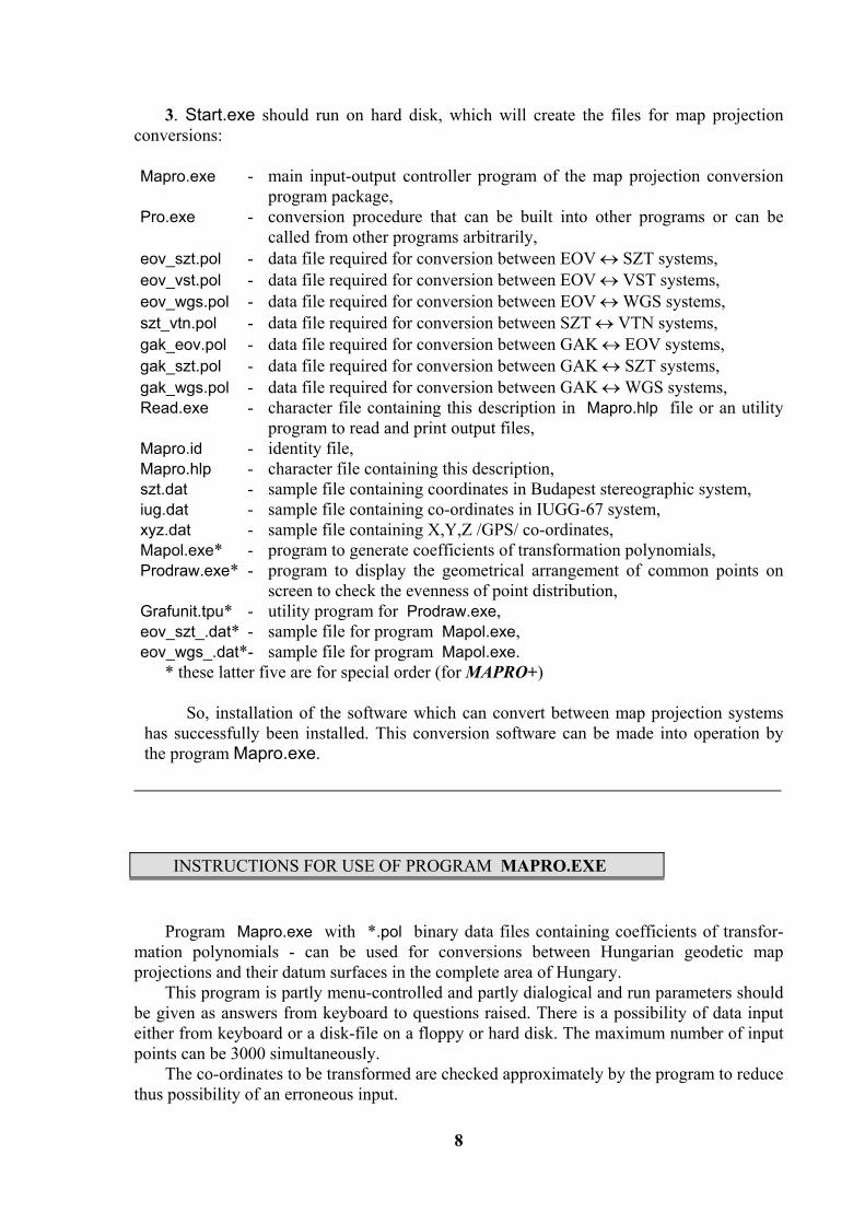
Fig. 1 Program Prodraw.exe is also a member of Module 1 by which the geometrical arrangement of common points can be displayed on screen to check the evenness of our point distribution. Actual conversions can be made by Module 2 (Fig. 1). Three important programs can be found in this module: input-output organizer program of the conversion software, namely Mapro.exe, main conversion program Pro.exe and Read.exe is an utility program to read and print output files. Co-ordinates of points to be converted can be inputted from both keyboard and disk files by the program Mapro.exe. A built-in special editor helps to handle co-ordinates from the keyboard or to transfer them into a work file work.dat in the required format. This special editor also serves to check inputted co-ordinates on a high level and therefore it is practically impossible to read errorneous co-ordinates. Co-ordinates from disk files will also pass through the above strict trouble shooting process and they will be transferred into a work file work.dat as well. Co-ordinates in the work file work.dat are transformed into the required system by the main conversion program Pro.exe. The operation of this main program and the conversion logic between the 15 different map projection systems can be overviewed on Fig. 2. Transformation paths − and their directions − between different systems are pictured by arrows. It can be seen that in most cases it is possible to convert between two arbitrary systems only through other intermediate systems (e.g. if a conversion between UTM and EOV systems is needed then UTM co-ordinates first have to be converted into WGS-84 ellipsoid, then into the new Gaussian sphere and then into a so-called auxiliary system and

7
finally they should be converted from this SVR system into EOV). If any two systems are connected in Fig. 2 by a continuous line then an exact conversion by the co-ordinate method, i.e. through closed mathematical expressions can be made; when the path, however, passes through an hexagonal block then the two systems, pointed by arrows, only a approximately accurate conversion could be made by transformation ploynomials. Two-letter abbreviations in hexagonal blocks show which binary data file, containing transformation polynomials, have to be used to convert between the two neighbouring systems (their meaning in accord with Fig. 1 is: ES = eov_szt.pol, EV = eov_vst.pol, EW = eov_wgs.pol, SV = szt_vtn.pol, GE = gak_eov.pol, GS = gak_szt.pol, GW = gak_wgs.pol). When there is more than one path possible between any two systems, the path is chosen along which conversion is more accurate. Transformed co-ordinates in different formats are passed into out.dat and trf.dat files by program Pro.exe.
HER HKR
SZTKST
VTN
GAK
EOV
OGS NGS
BES KRA IUG
NGS
WGS
UTM
AUX
GW
EW
GE
EV
ES
GS
XYZ ABE
AGK
AW
Fig. 2
Read.exe is a utility program that serves to display (read) and print output files. The content of the output file out.dat can be examined by this program on the screen and it can also be printed optionally.
INSTALLING THE PROGRAM It is recommended to start the programs from a hard disk therefore it has to be installed from the installation disk. Two files are found on the installation disk: Setup.txt (text file containing the information of installation) and Start.exe (containing the transformation software MAPRO or MAPRO+ in compressed, auto-unpack form.) Installation of the software MAPRO : 1. A new folder should be created on hard disk where the software MAPRO will be installed to. 2. Start.exe should copy from floppy to this folder on hard disk.
8
3. Start.exe should run on hard disk, which will create the files for map projection conversions: Mapro.exe - main input-output controller program of the map projection conversion
program package, Pro.exe - conversion procedure that can be built into other programs or can be
called from other programs arbitrarily, eov_szt.pol - data file required for conversion between EOV ↔ SZT systems, eov_vst.pol - data file required for conversion between EOV ↔ VST systems, eov_wgs.pol - data file required for conversion between EOV ↔ WGS systems, szt_vtn.pol - data file required for conversion between SZT ↔ VTN systems, gak_eov.pol - data file required for conversion between GAK ↔ EOV systems, gak_szt.pol - data file required for conversion between GAK ↔ SZT systems, gak_wgs.pol - data file required for conversion between GAK ↔ WGS systems, Read.exe - character file containing this description in Mapro.hlp file or an utility
program to read and print output files, Mapro.id - identity file, Mapro.hlp - character file containing this description, szt.dat - sample file containing coordinates in Budapest stereographic system, iug.dat - sample file containing co-ordinates in IUGG-67 system, xyz.dat - sample file containing X,Y,Z /GPS/ co-ordinates, Mapol.exe* - program to generate coefficients of transformation polynomials, Prodraw.exe* - program to display the geometrical arrangement of common points on
screen to check the evenness of point distribution, Grafunit.tpu* - utility program for Prodraw.exe, eov_szt_.dat* - sample file for program Mapol.exe, eov_wgs_.dat*- sample file for program Mapol.exe.
* these latter five are for special order (for MAPRO+)
So, installation of the software which can convert between map projection systems has successfully been installed. This conversion software can be made into operation by the program Mapro.exe.
INSTRUCTIONS FOR USE OF PROGRAM MAPRO.EXE Program Mapro.exe with *.pol binary data files containing coefficients of transfor-mation polynomials - can be used for conversions between Hungarian geodetic map projections and their datum surfaces in the complete area of Hungary. This program is partly menu-controlled and partly dialogical and run parameters should be given as answers from keyboard to questions raised. There is a possibility of data input either from keyboard or a disk-file on a floppy or hard disk. The maximum number of input points can be 3000 simultaneously. The co-ordinates to be transformed are checked approximately by the program to reduce thus possibility of an erroneous input.

9
Output results are displayed on screen but it is possible to direct these results to a floppy or a hard disk file or to a printer as well. Let us change into the directory where the program was installed before running! To run map projection conversion program type
MAPRO
and . At the program start a selection could be made whether to key in the co-ordinates to be transformed or they should be input from a disk-file after the following message had been displayed:
DO YOU WANT TO LOAD CO-ORDINATES FOR CONVERSION FROM A DISK FILE OR FROM KEYBOARD? ( D =from disk file; K =from keyboard) : _
Only d, D or k, K keystrokes will be accepted for an answer by the program, other keystrokes will be ignored. On the other hand an immediate advancement will take place after striking keys d, D or k, K without striking the key, and the next screen will appear to choose map projection systems from which and into which the conversion of co-ordinates are required. From systems listed on the left side of the screen, which shows our choice items, the conversion may take place into systems listed on the right side. The selection is very simple using mouse, or , cursor keys toggle between left and right side menus and , cursor keys serve to select the projection system required by moving a highlighted row. After the selection of required map projection systems in both left and right side menus had been successful we may go on by striking the key or clicking to the "<Enter>" by mouse. To select the same map projection system in both left and right side menus is not allowed since an identity transformation has no meaning. The only two exceptions are the Gauss-Krüger and UTM map projection systems when a conversion between neighbouring zones of these projections are required. When Gauss-Krüger or UTM co-ordinates are required to convert the following question will be displayed:
PLEASE GIVE LAMBDA CO-ORDINATE OF THE CENTRAL MERIDIAN TO WHICH GAUSS-KRUGER (OR UTM) CO-ORDINATES TO BE TRANSFORMED SHOULD REFER: __
and the answer should contain the latitude of central meridian in case of Gauss-Krüger projection in integer degrees (central meridian should be 15o or 21o in Hungary). Central meridian besides of degrees 3, 9, 15, 21 and 27 will not be accepted at all; - even within these values 3, 9 or 27 are inputted the
A CENTRAL MERIDIAN NOT BELONGING TO THE AREA OF HUNGARY! warning message is sent to the screen, (but the conversion apart from this will be performed).
10
Central meridians of UTM Co-ordinates may not only be integers but may be arbitrary real values in ‘degrees-minutes’ form. Guide number of co-ordinates must be given in case of 15 o and 21 o integer central meridians for Gauss-Krüger and UTM projection systems. (We have to be added 3500000m to all Y co-ordinates in case of 15 degree central meridian, and 4500000m in case of 21 degree central meridian.) In case of any other central meridians of UTM system (non zero values of minutes) guide numbers ( 3500000 or 4500000 ) must not be add to Y co-ordinates. If Gauss-Krüger co-ordinates are to be determined from co-ordinates in an arbitrary map projection system then the following question will be displayed:
PLEASE GIVE LAMBDA CO-ORDINATE OF THE CENTRAL MERIDIAN TO WHICH TRANSFORMED GAUSS-KRUGER (OR UTM) CO-ORDINATES SHOULD REFER: __
and the answer should contain the latitude of central meridian in integer degrees. Central meridian besides of degrees 3, 9, 15, 19, 21 and 27 will not even here be accepted; - and after inputting values 3, 9 or 27 the
A CENTRAL MERIDIAN NOT BELONGING TO THE AREA OF HUNGARY! warning message will be displayed, (the conversion here also will be performed apart from this message). Transformation software gives the Gauss-Krüger and UTM Y co-ordinates with the guide number of 3 for central meridian of 15 degrees (Y=Y+3500000m) and guide number 4 for central meridian of 21 degrees (Y=Y+4500000m). But UTM co-ordinates can transform to arbitrary central meridians. In case of integer degrees (non zero minutes) of central meridian, the transformed UTM co-ordinates don’t contain guide numbers. As it was mentioned there is a possibility with program Mapro.exe also to make conversions between different zones of the Gauss-Krüger or UTM projection. In this case latitudes of central meridian belonging to both co-ordinates transformed and co-ordinates to be transformed should be provided as answers to the above question raised. When it was selected at program start to load co-ordinates for conversion from a diskfile then after choosing the type (direction) of the transformation the input file name and directory should be inputted in the following format: [drive] [directory] data file name as an answer to the question
PLEASE GIVE DRIVE, DIRECTORY AND INPUT FILE NAME WHERE CO-ORDINATES FOR CONVERSION ARE LOCATED:
displayed on the screen. For example if co-ordinates to be transformed are located in file szt.dat and this file is in the directory DATA on the floppy disk in drive A: then the inputted file should be defined as A:\DATA\SZT.DAT
11
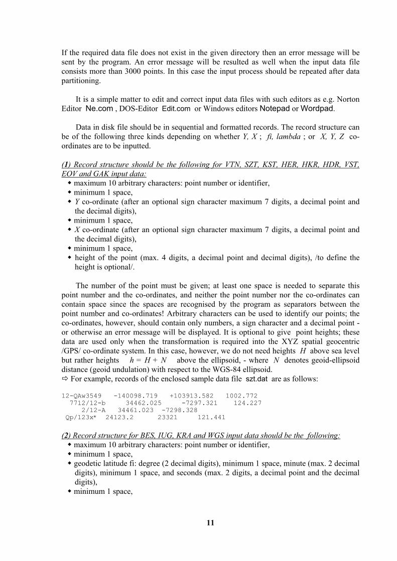
If the required data file does not exist in the given directory then an error message will be sent by the program. An error message will be resulted as well when the input data file consists more than 3000 points. In this case the input process should be repeated after data partitioning. It is a simple matter to edit and correct input data files with such editors as e.g. Norton Editor Ne.com , DOS-Editor Edit.com or Windows editors Notepad or Wordpad. Data in disk file should be in sequential and formatted records. The record structure can be of the following three kinds depending on whether Y, X ; fi, lambda ; or X, Y, Z co-ordinates are to be inputted. (1) Record structure should be the following for VTN, SZT, KST, HER, HKR, HDR, VST, EOV and GAK input data:
maximum 10 arbitrary characters: point number or identifier, minimum 1 space, Y co-ordinate (after an optional sign character maximum 7 digits, a decimal point and the decimal digits),
minimum 1 space, X co-ordinate (after an optional sign character maximum 7 digits, a decimal point and the decimal digits),
minimum 1 space, height of the point (max. 4 digits, a decimal point and decimal digits), /to define the height is optional/.
The number of the point must be given; at least one space is needed to separate this point number and the co-ordinates, and neither the point number nor the co-ordinates can contain space since the spaces are recognised by the program as separators between the point number and co-ordinates! Arbitrary characters can be used to identify our points; the co-ordinates, however, should contain only numbers, a sign character and a decimal point - or otherwise an error message will be displayed. It is optional to give point heights; these data are used only when the transformation is required into the XYZ spatial geocentric /GPS/ co-ordinate system. In this case, however, we do not need heights H above sea level but rather heights h = H + N above the ellipsoid, - where N denotes geoid-ellipsoid distance (geoid undulation) with respect to the WGS-84 ellipsoid.
For example, records of the enclosed sample data file szt.dat are as follows: 12-QAw3549 -140098.719 +103913.582 1002.772 7712/12-b 34462.025 -7297.321 124.227 2/12-A 34461.023 -7298.328 Qp/123x* 24123.2 23321 121.441 (2) Record structure for BES, IUG, KRA and WGS input data should be the following:
maximum 10 arbitrary characters: point number or identifier, minimum 1 space, geodetic latitude fi: degree (2 decimal digits), minimum 1 space, minute (max. 2 decimal digits), minimum 1 space, and seconds (max. 2 digits, a decimal point and the decimal digits),
minimum 1 space,

12
geodetic longitude lambda: degree (2 decimal digits), minimum 1 space, minute (max. 2 decimal digits), minimum 1 space, and seconds (max. 2 digits, a decimal point and the decimal digits),
minimum 1 space, height of the point (max. 4 digits, a decimal point and decimal digits), / to define the height is optional /.
The number of the point must be given; at least one space character is needed here also to separate point number and the fi, lambda co-ordinates, and also the degree, minute and second values inside these co-ordinates; and neither the point number nor the co-ordinates nor degree, minute and second values can contain a blank space inside since these spaces are recognised by the program as separators between the point number and co-ordinates! Arbitrary characters can be used to identify our points; the co-ordinates, however, should contain only numbers, a sign character and a decimal point - or otherwise an error message will be displayed. Here it is also optional to give point heights; these data are used only when the transformation is required into the XYZ spatial geocentric /GPS/ co-ordinate system. In this case, however, we do not need heights H above sea level but rather heights h = H + N above the ellipsoid, - where N denotes geoid-ellipsoid distance (geoid undulation) with respect to the WGS-84 ellipsoid.
For example, records of the enclosed sample data file iug.dat are as follows: 12-QAW3549 46 32 16.2163 20 52 29.8588 1002.772 7712/12-A 47 33 06.7133 18 35 26.6448 124.227 2/12-A 47 33 06.7 18 0 0.6448 Qp/123x* 46 2 0.01 19 0 12.22 122.1 (3) Record structure should be the following for inputted XYZ data:
maximum 10 arbitrary characters: point number or identifier, minimum 1 space, Y co-ordinate (after an optional sign character maximum 7 digits, a decimal point and the decimal digits),
minimum 1 space, X co-ordinate (after an optional sign character maximum 7 digits, a decimal point and the decimal digits),
minimum 1 space, Z co-ordinate (after an optional sign character maximum 7 digits, a decimal point and the decimal digits).
The number of the point must be given; at least one space character is needed to separate this point number and the co-ordinates, and neither the point number nor the co-ordinates can contain a blank space since these spaces are recognised by the program as separators between the point number and co-ordinates! Arbitrary characters can be used to identify our points; the co-ordinates, however, should contain only numbers, a sign character and a decimal point - or otherwise an error message will be displayed. (It should be noted here that when an XYZ spatial geocentric co-ordinate is transformed into any other system then the heights resulted will not be those H referred to the sea level but rather the heights h = H + N referred to the WGS-84 ellipsoid, where N denotes geoid-ellipsoid distance (geoid undulation) with respect to the WGS-84 ellipsoid.)
For example, records of the enclosed sample data file xyz.dat are as follows: 12-QAW3549 4107321.877 1566285.815 4607281.520 7712/12-b 4087711.987 1374842.483 4683461.163

13
7712/12-A 4087711.98 1374842.483 4683461.1 Qp/123x* 4122343.3 1455554.443 4677443.334 When the format of inputted data is unsuitable for the program (for example besides numerical characters some other character is contained in any of the co-ordinates), then the error message
DATA ERROR IN THE nth ROW OF THE INPUT FILE will give us a warning. Now by pressing the <Esc> key the program will be interrupted and a correction could be made in the erroneous line, or by pressing the key this erroneous line will be omitted from processing and the next line of the input file will be read and checked. When a co-ordinate to be transformed lies outside the area of Hungary then the following error message will warn us:
A CO-ORDINATE NOT BELONGING TO THE HUNGARIAN .. /e.g.: EOV/ .. SYSTEM OCCURRED IN THE nth ROW OF THE INPUT FILE!
Now by pressing the <Esc> key the program will be interrupted and a correction could be made in the erroneous line, by pressing the <Del> key this erroneous line will be omitted from processing and the next line of the input file will be checked, and when one presses the
key this enforces the program to make an attempt to convert a co-ordinate outside the area of Hungary, - this may result in a co-ordinate of no use (and in the output list " ***** " characters will appear instead of these faulty data). If our answer is K to the previously mentioned question DO YOU WANT TO LOAD CO-ORDINATES FOR CONVERSION FROM A DISKFILE OR FROM KEYBOARD? ( D =from disk file; K =from keyboard) : _ at the program start then we may follow an another program line and a special editor will start for the actual screen format depending on whether Y, X ; fi, lambda ; or X, Y, Z type co-ordinates have to be the input and by this editor one is able to inkey co-ordinates to be transformed pointwise. That area is always highlighted where the actual input takes place (e.g. the point number, the Y or X co-ordinate). Any time the key may be used to get some help how to use this editor. The highlighted area can be scrolled forward and backward by the or and cursor keys, respectively. Inside the selected area the , cursor keys or the <Backspace> key can be used. The point number (identifier) is optional but the rows of co-ordinates have to be filled even when they are zero. The heights of points are optional as it was previously mentioned. These are used only when one would like to convert into the XYZ spatial geocentric /GPS/ system. In this case, however, one needs not the H heights above sea level but the heights h = H + N above ellipsoid, - where N denotes geoid-ellipsoid distance (geoid undulation) with respect to the WGS-84 ellipsoid. After all the required data of a given point had been keyed in and the co-ordinates on the screen seemed free of error then by pressing the key the data of the actual point are copied into the list of points to be transformed (into the memory). Then the editor is free to receive the next point for input.

14
One can quit the editor program by pressing the key (and this will initiate the transformation of inkeyed co-ordinates). A check of the data of any point on the screen will be performed after pressing the key and only those data will be loaded into the memory which are completely acceptable in all respect. Otherwise an error message will be displayed and the cursor will show the erroneous input to make debugging more effective. An erroneous input by no means will be accepted; it is possible only to enforce the acceptance of such co-ordinates which do not lie inside the area of Hungary. If any of the co-ordinates to be transformed lies outside the area of Hungary an error message will be displayed. In this case, by pressing the <Esc> key the cursor jumps back to the "not Hungarian co-ordinate" and the erroneous co-ordinate may be corrected. Or otherwise, by pressing the key the acceptance of such a not Hungarian co-ordinate can be enforced and an attempt is initiated to transform this point. Of course there is a chance that the transformed co-ordinates will be of no use (in such a case "*****" characters will be found in the output list instead of the erroneous co-ordinate). After inkeying the last co-ordinate required it should be remembered to press the key prior to the key if we would like to have this point also in the input list of co-ordinates to be transformed. There is a possibility in the program to save the inkeyed co-ordinates into a file for further processing if a y or Y answer was given to the DO YOU WANT TO SAVE THE INKEYED DATA INTO A FILE? ( Y = Yes; N = No ) : _ question. Then the following question will appear on the screen:
PLEASE GIVE THE (DRIVE, DIRECTORY /PATH/ AND THE) NAME OF THE OUTPUT FILE WHERE YOU WANT TO SAVE THE INKEYED DATA TO:
The answer to this question should be the file name (and directory also when the file is not in the actual directory) in the following format: [drive] [directory] filename For example, if we would like to save the input from the keyboard on disk in drive B: into the stereo.dat file in directory DATA then this format should be the following: B:\DATA\STEREO.DAT If the inkeyed data were not backed up in spite of the possibility that was offered, (and at later times, however, they are required anew) there is a hope to use them again, - since a work.dat work file is always created from the input data, let them be from the keyboard or from a disk file, the content of which is accessible till the re-start of the program Mapro.exe. Then there is a possibility to write the transformed co-ordinates into a disk file as well - if to the next question on the screen
DO YOU WANT TO SAVE TRANSFORMED CO-ORDINATES ALSO INTO A DISK FILE? ( Y=yes; N=no ) : _
15
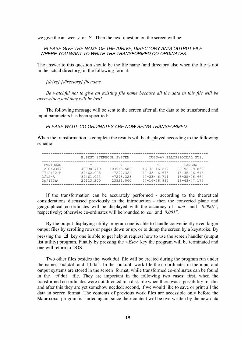
we give the answer y or Y . Then the next question on the screen will be:
PLEASE GIVE THE NAME OF THE (DRIVE, DIRECTORY AND) OUTPUT FILE WHERE YOU WANT TO WRITE THE TRANSFORMED CO-ORDINATES:
The answer to this question should be the file name (and directory also when the file is not in the actual directory) in the following format: [drive] [directory] filename Be watchful not to give an existing file name because all the data in this file will be overwritten and they will be lost! The following message will be sent to the screen after all the data to be transformed and input parameters has been specified:
PLEASE WAIT! CO-ORDINATES ARE NOW BEING TRANSFORMED. When the transformation is complete the results will be displayed according to the following scheme ---------------------------------------------------------------------------- B.PEST STEREOGR.SYSTEM IUGG-67 ELLIPSZOIDAL SYS. ---------------------------------------------------------------------------- PONTSZAM Y X FI LAMBDA 12-QAw3549 -140098.719 103913.582 46-32-16.217 20-52-29.862 7712/12-b 34462.025 -7297.321 47-33- 6.678 18-35-26.616 2/12-A 34461.023 -7298.328 47-33- 6.711 18-35-26.664 Qp/123x* 24123.200 23321.000 47-16-36.992 18-43-47.173 ----------------------------------------------------------------------------
If the transformation can be accurately performed - according to the theoretical considerations discussed previously in the introduction - then the converted plane and geographical co-ordinates will be displayed with the accuracy of mm and 0.0001", respectively; otherwise co-ordinates will be rounded to cm and 0.001". By the output displaying utility program one is able to handle conveniently even larger output files by scrolling rows or pages down or up, or to dump the screen by a keystroke. By pressing the key one is able to get help at request how to use the screen handler (output list utility) program. Finally by pressing the <Esc> key the program will be terminated and one will return to DOS. Two other files besides the work.dat file will be created during the program run under the names out.dat and trf.dat . In the out.dat work file the co-ordinates in the input and output systems are stored in the screen format, while transformed co-ordinates can be found in the trf.dat file. They are important in the following two cases: first, when the transformed co-ordinates were not directed to a disk file when there was a possibility for this and after this they are yet somehow needed; second, if we would like to save or print all the data in screen format. The contents of previous work files are accessible only before the Mapro.exe program is started again, since their content will be overwritten by the new data

16
again and again. The most simple way to save and archive their content is to give them a new different name. Transformed co-ordinates will be written in the disk file according to their input sequence and in each case the height of the point is also listed. When no height was defined in the program input then the 0.0 value will be printed. If the transformation can be accurately performed - according to the theoretical considerations discussed previously in the introduction - then the converted plane and geographical co-ordinates will be listed with the accuracy of mm and 0.0001", respectively; otherwise co-ordinates will be rounded to cm and 0.001" and these rounded co-ordinates will be written into the output file. We would like to mention here that the Pro.exe program in the MAPRO program package which actually does the conversion between the projection systems may be used, when it is necessary, as an independent subroutine. Since the Pro.exe program in the MAPRO package is called by the main input-output and general error handler program Mapro.exe , so before we would like to use it as an independent subroutine it is necessary to create for it the work.dat work file. This file, after some certain control characters, contains the co-ordinates to be transformed in a fixed special format. This special data format can be learned most simply by studying the work.dat file as it is created by the Mapro.exe program. The first records (rows) of the data file work.dat contains four integer type number in a fixed format (four times after one another: 2 integer digits and 2 blank spaces). The first integer number is the number of that projection system from which co-ordinates are to be transformed, the second is the number of the projection system into which co-ordinates are to be transformed. These numbers have the following meaning: 1 = SZT (Budapest stereographic projection) 2 = HER (North cylindrical projection system) 3 = HKR (middle cylindrical projection system) 4 = HDR (South cylindrical projection system) 5 = EOV (Unified National projection system) 6 = KST (Military stereographic projection) 7 = BES (Bessel's ellipsoidal co-ordinates) 8 = IUG (IUGG-67 ellipsoidal co-ordinates) 9 = GAK (Gauss-Krüger projection system) 10 = KRA (Krassovsky's ellipsoidal co-ordinates) 11 = WGS (WGS-84 ellipsoidal co-ordinates) 12 = XYZ (spatial geocentric Cartesian system /GPS/) 13 = VST (Budapest city stereographic projection) 14 = VTN (system without projection) 15 = UTM (Universal Transverse Mercator) The third (fourth) and fifth (sixth) integer type numbers has got their meaning only when the transformation takes place between the Gauss-Krüger or UTM system and any other system since these numbers are the lambda co-ordinates in degrees (and minutes) of the respective central meridians. Central meridians in minutes can be given only in case of UTM projection.

17
The other records (rows) of the work.dat work file contain data of points to be transformed in the following fixed format:
1 space, 10 arbitrary character: Point number or identifier, 2 spaces, in the next 12 places: Y co-ordinate (after an optional sign character maximum 7 digits, a decimal point and 3 decimal digits),
2 spaces, in the next 12 places: X co-ordinate (after an optional sign character maximum 7 digits, a decimal point and 3 decimal digits),
2 spaces, and finally in the last 12 places: the height of point (max. 7 digits, a decimal point and 3 decimal digits), or instead, blank spaces if one does not want to specify the height.
If fi, lambda ellipsoidal co-ordinates are the input instead of plane Y,X co-ordinates, then the above Y or X value is 100000 times the fi latitude or lambda longitude after they have been converted into degrees and fractions of degree. If, however, XYZ spatial geocentric co-ordinates are the input instead of Y,X plane co-ordinates then the above Y value is the geocentric X, the above X value is the geocentric Y, and the above height is the geocentric Z co-ordinate. Two files are created by the program: out.dat and trf.dat . In the out.dat file co-ordinates both before and after the transformation are stored together but in the trf.dat file only transformed co-ordinates can be found.
INSTRUCTIONS FOR USE OF PROGRAM MAPOL.EXE When transformation polynomials are used data files containing the coefficients of these polynomials can be altered or refined. The program Mapol.exe makes it possible to do this by using arbitrary common points to determine new coefficients of transformation polynomials for the Pro.exe program. It is recommended to use the program Mapol.exe only for those specialists who have a deep knowledge and thorough experience in the field of map projection systems! By this program it is possible to create binary data files eov_szt.pol, eov_vst.pol, eov_wgs.pol, gak_eov.pol, gak_szt.pol, gak_wgs.pol and szt_vtn.pol containing the coefficients of transformation polynomials that are required for conversion between the EOV - Budapest stereographic, EOV - Budapest city stereographic, EOV - WGS-84, Gauss-Krüger - EOV, Gauss-Krüger - Budapest stereographic, Gauss-Krüger - WGS-84 and Budapest stereographic - system without projection, based on given common points. The need arises to use Mapol.exe program when new polynomial coefficients are required for the program Pro.exe to make the transformation more accurate - either for the complete area of Hungary by increasing the number of common points, - or for a smaller area by using local common points.

18
Before program use let us change into the directory where our map projection conversion software was installed! The MAPOL command should be used to start our program. After the program Mapol.exe log-in the next question will be displayed:
PLEASE GIVE THE TWO SYSTEMS THE COEFFICIENTS OF TRANSFOR- MATION POLYNOMIALS ARE TO BE DETERMINED BETWEEN:
CHOOSE FROM THE FOLLOWING ONES:
1 = EOV - Budapest stereographic 2 = EOV - Budapest city stereographic 3 = EOV - WGS - 84 4 = Gauss-Krüger - EOV 5 = Gauss-Krüger - Budapest stereogr. 6 = Gauss-Krüger - WGS-84 7 = Budapest stereogr. - without proj.
ENTER YOUR CHOICE (1..7) ?: _ Of course it is possible to answer by a number between 1 and 7. Then for the next question PLEASE GIVE DRIVE, DIRECTORY AND INPUT FILE NAME WHERE THE EOV - ........................ COMMON POINTS CAN BE FIND: the input file name and directory should be the answer in the following form: [drive] [directory] data file name where common points are located. For example if our common points are located in the eov_szt.dat file, and this file is in the directory DATA on the floppy drive A: then the input data file should be specified as A:\DATA\EOV_SZT.DAT The editing and updating of input data files can be done simply by using e.g. Norton Editor Ne.com , DOS-Editor Edit.com or Windows editors Notepad or Wordpad. The record structure of data in input files must be sequential and formatted, and they must contain the data of minimum 6 common points. The record structure of input files can be of the following two types: (1) The record structure of input data in the EOV - Budapest city stereographic, Gauss-Kruger - EOV, Gauss-Kruger - Budapest stereographic and Budapest stereographic - system without projection systems should be the following:
1 space, 10 arbitrary characters: point number or identifier, 2 spaces,

19
in the next 12 places: the Y co-ordinate in the EOV, Gauss-Krüger or in the Budapest stereographic system /depending on the systems one would like to compute the coefficients of transformation polynomials/ (after an optional sign character maximum 7 digits, a decimal point and 3 decimal digits),
2 spaces, in the next 12 places: the X co-ordinate in the EOV, Gauss-Krüger or in the Budapest stereographic system /depending on the systems one would like to compute the coefficients of transformation polynomials/ (after an optional sign character maximum 7 digits, a decimal point and 3 decimal digits),
2 spaces, in the next 12 places: the Y co-ordinate in the Budapest stereographic system, Budapest city stereographic system, EOV, or in the system without projection /depending on the systems one would like to compute the coefficients of transformation polynomials/ (after an optional sign character maximum 7 digits, a decimal point and 3 decimal digits),
2 spaces, in the next 12 places: the X co-ordinate in the Budapest stereographic system, Budapest city stereographic system, EOV, or in the system without projection /depending on the systems one would like to compute the coefficients of transformation polynomials/ (after an optional sign character maximum 7 digits, a decimal point and 3 decimal digits).
For example these are the records of the sample EOV_SZT_.DAT file:
SOPRON 461890.650 269073.740 188129.290 -31004.460 TARPA 910606.270 315389.150 -260632.370 -77334.500 .......... (2) When the common points are between the systems EOV - WGS-84 or between the systems Gauss-Krüger - WGS-84 the following format is valid:
1 space, 10 arbitrary character: point number or identifier, 2 spaces, in the next 12 places: the Y co-ordinate in the EOV or Gauss-Krüger system (after an optional sign character maximum 7 digits, a decimal point and 3 decimal digits),
2 spaces, in the next 12 places: the X co-ordinate in the EOV or Gauss-Krüger system (after an optional sign character maximum 7 digits, a decimal point and 3 decimal digits),
2 spaces, geodetic latitude fi in the WGS-84 system: degree (2 digits), 1 space, minute (2 digits), 1 space, and seconds (2 digits, a decimal point and 4 decimal digits),
2 spaces, geodetic longitude lambda in the WGS-84 system: degree (2 digits), 1 space, minute (2 digits), 1 space, and seconds (2 digits, a decimal point and 4 decimal digits).
For example these are the records of the sample EOV_WGS_.DAT file:
HAJDUDOROG 834572.608 280059.946 47 50 16.9833 21 30 48.4037 SOPRON 466457.988 258621.351 47 38 44.0913 16 36 14.9602 .......... After defining the input file the following question will be displayed:
20
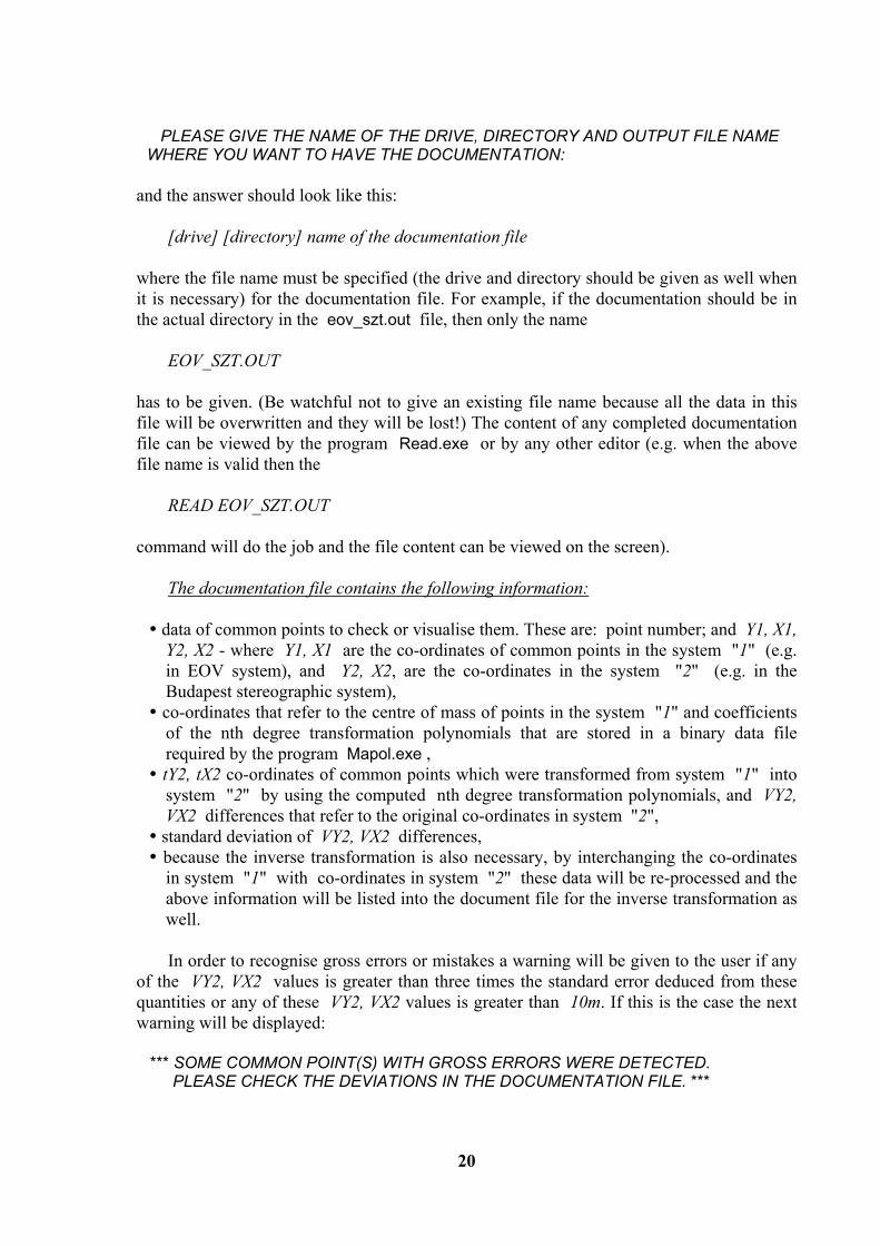
PLEASE GIVE THE NAME OF THE DRIVE, DIRECTORY AND OUTPUT FILE NAME WHERE YOU WANT TO HAVE THE DOCUMENTATION:
and the answer should look like this: [drive] [directory] name of the documentation file where the file name must be specified (the drive and directory should be given as well when it is necessary) for the documentation file. For example, if the documentation should be in the actual directory in the eov_szt.out file, then only the name EOV_SZT.OUT has to be given. (Be watchful not to give an existing file name because all the data in this file will be overwritten and they will be lost!) The content of any completed documentation file can be viewed by the program Read.exe or by any other editor (e.g. when the above file name is valid then the READ EOV_SZT.OUT command will do the job and the file content can be viewed on the screen). The documentation file contains the following information:
data of common points to check or visualise them. These are: point number; and Y1, X1, Y2, X2 - where Y1, X1 are the co-ordinates of common points in the system "1" (e.g. in EOV system), and Y2, X2, are the co-ordinates in the system "2" (e.g. in the Budapest stereographic system),
co-ordinates that refer to the centre of mass of points in the system "1" and coefficients of the nth degree transformation polynomials that are stored in a binary data file required by the program Mapol.exe ,
tY2, tX2 co-ordinates of common points which were transformed from system "1" into system "2" by using the computed nth degree transformation polynomials, and VY2, VX2 differences that refer to the original co-ordinates in system "2",
standard deviation of VY2, VX2 differences, because the inverse transformation is also necessary, by interchanging the co-ordinates in system "1" with co-ordinates in system "2" these data will be re-processed and the above information will be listed into the document file for the inverse transformation as well.
In order to recognise gross errors or mistakes a warning will be given to the user if any of the VY2, VX2 values is greater than three times the standard error deduced from these quantities or any of these VY2, VX2 values is greater than 10m. If this is the case the next warning will be displayed: *** SOME COMMON POINT(S) WITH GROSS ERRORS WERE DETECTED. PLEASE CHECK THE DEVIATIONS IN THE DOCUMENTATION FILE. ***

21
We must be careful when we use program Mapol.exe since the binary data files eov_szt.pol, eov_vst.pol, eov_wgs.pol, gak_eov.pol, gak_szt.pol, gak_wgs.pol and szt_vtn.pol that are required for the program Pro.exe are automatically generated by the program in such a way that the contents of existing data files are overwritten. Therefore when the defined data file already exist in the actual directory then a warning will be given and there is a choice to overwrite it or not. If one would like to keep the old data file as well, then it is recommended to copy it into another directory or to save it on a floppy disk before the program start. Later, however, take a good care not to confuse them (for example these files can be distinguished according to their dates of creation). Because of the reasons that has been mentioned already it is possible to make only approximate conversions between certain projection systems and their reference surfaces for the complete area of the country. In these cases the conversion is possible only through some transformation equations that were created by using common points (i.e. such points that have got co-ordinates in both systems). Consequently, the accuracy of conversion can be increased slightly by increasing the number of common points but it is not possible to increase the accuracy beyond a certain limit, because the reference surfaces and also the control networks are different. In most cases the accuracy of the conversion can only be increased significantly when the coefficients of transformation polynomials are not determined for the whole area of the country but only for smaller areas we give common points and thus we compute the coefficients of transformation polynomials by our program Mapol.exe . Of course, when we determined the coefficients for only a local area by the program Mapol.exe then inside only this local area we are permitted to make the conversion with the Mapro.exe program.
INSTRUCTIONS FOR USE OF PROGRAM PRODRAW.EXE It can be important to know the distribution of points when we want to determine the polynomial coefficients. It is suitable to distribute the common points in any case that they may surround the given area and may fill it homogeneously and with a good density. It is possible to view the area distribution of common points by the program Prodraw.exe . The points of data files that were created for the program Mapol.exe can be plotted on the screen based on their co-ordinates with the aid of this utility program. This program works well with VGA, eGA and Hercules graphic cards. The optimal size and location of points is determined automatically such that the network points may fill the entire screen completely with no distortion and at the same time not even one of them should be absent. Before starting the program let us change into the directory where map projection conversion software was installed! The PRODRAW command will start the program. After the program's login the input data file name and directory has to be defined in the next form: [drive] [directory] data file name
22
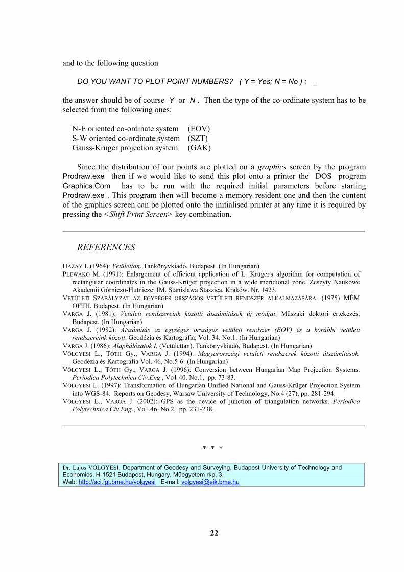
and to the following question DO YOU WANT TO PLOT POINT NUMBERS? ( Y = Yes; N = No ) : _ the answer should be of course Y or N . Then the type of the co-ordinate system has to be selected from the following ones: N-E oriented co-ordinate system (EOV) S-W oriented co-ordinate system (SZT) Gauss-Kruger projection system (GAK) Since the distribution of our points are plotted on a graphics screen by the program Prodraw.exe then if we would like to send this plot onto a printer the DOS program Graphics.Com has to be run with the required initial parameters before starting Prodraw.exe . This program then will become a memory resident one and then the content of the graphics screen can be plotted onto the initialised printer at any time it is required by pressing the <Shift Print Screen> key combination.
REFERENCES HAZAY I. (1964): Vetülettan. Tankönyvkiadó, Budapest. (In Hungarian) PLEWAKO M. (1991): Enlargement of efficient application of L. Krüger's algorithm for computation of
rectangular coordinates in the Gauss-Krüger projection in a wide meridional zone. Zeszyty Naukowe Akademii Górniczo-Hutniczej IM. Stanislawa Staszica, Kraków. Nr. 1423.
VETÜLETI SZABÁLYZAT AZ EGYSÉGES ORSZÁGOS VETÜLETI RENDSZER ALKALMAZÁSÁRA. (1975) MÉM OFTH, Budapest. (In Hungarian)
VARGA J. (1981): Vetületi rendszereink közötti átszámítások új módjai. Műszaki doktori értekezés, Budapest. (In Hungarian)
VARGA J. (1982): Átszámítás az egységes országos vetületi rendszer (EOV) és a korábbi vetületi rendszereink között. Geodézia és Kartográfia, Vol. 34. No.1. (In Hungarian)
VARGA J. (1986): Alaphálózatok I. (Vetülettan). Tankönyvkiadó, Budapest. (In Hungarian) VÖLGYESI L., TÓTH Gy., VARGA J. (1994): Magyarországi vetületi rendszerek közötti átszámítások.
Geodézia és Kartográfia Vol. 46, No.5-6. (In Hungarian) VÖLGYESI L., TÓTH Gy., VARGA J. (1996): Conversion between Hungarian Map Projection Systems.
Periodica Polytechnica Civ.Eng., Vo1.40. No.1, pp. 73-83. VÖLGYESI L. (1997): Transformation of Hungarian Unified National and Gauss-Krüger Projection System
into WGS-84. Reports on Geodesy, Warsaw University of Technology, No.4 (27), pp. 281-294. VÖLGYESI L., VARGA J. (2002): GPS as the device of junction of triangulation networks. Periodica
Polytechnica Civ.Eng., Vo1.46. No.2, pp. 231-238.
* * * Dr. Lajos VÖLGYESI, Department of Geodesy and Surveying, Budapest University of Technology and Economics, H-1521 Budapest, Hungary, Műegyetem rkp. 3. Web: http://sci.fgt.bme.hu/volgyesi E-mail: [email protected]