converter idtmf/inductive itx 422 43, itx 422 43.2, itx 482 43, itx 482 43.2 v04 3 2. device...
TRANSCRIPT
CONVERTER CONVERTER CONVERTER CONVERTER
IDTMF/INDUCTIVEIDTMF/INDUCTIVEIDTMF/INDUCTIVEIDTMF/INDUCTIVE
PRODUCT PRODUCT PRODUCT PRODUCT DODODODOCUMENTATIONCUMENTATIONCUMENTATIONCUMENTATION
ITX 422 43, ITX 422 43.2, ITX 482 43, ITX 482 43.2
V04 1
CONTENTS 1. General ....................................................................... 2 2. Device description ....................................................................... 3 3. Device function ....................................................................... 4 4. Mechanical assembly ......................................................... 5 5. Connecting and setting-up ......................................................... 7 6. Technical parameters ......................................................... 12
7. Converter DC/DC .......................................................................... 13 8. Rack assembly .......................................................................... 14
ITX 422 43, ITX 422 43.2, ITX 482 43, ITX 482 43.2
V04 2
1. GENERAL
Name: Signalling converter IDTMF, E&M / Inductive Type nomenclature: ITX 422 43, ITX 422 43.2 (rack cards), ITX 482 43, ITX 482 43.2
Manufacturer: INOTESKA, s.r.o.
Placement: in supervised areas
Dimensions: ITX 482 43 : 43.5 x 237 x 220 mm (h x w x d) ITX 482 43.2 : 55 x 237 x 220 mm (h x w x d) Operational conditions: 0
o C to 55
o C, 20% to 75% relative atmospheric humidity
Storage: -10o C to 60
o C, 20% to 75% relative atmospheric humidity
Basic parameters:
� dual signalling converter IDTMF, E&M / Inductive � input/output - IDTMF signalling - 2-wire - 4-wire
� input/output - E&M signalling pulsed or permanent - 2-wire - 4-wire � input/output to conducting - inductive signalling - 2-wire � PbX power supply - 42 to 65 V DC, current Imax = 1A Note: When switching on, build-up current is higher. � wires are connected by connectors � wall mounting or desktop placement � Possibility of placement to the 19” rack 6U � pulse signalling range – to the line with resistance max. 3000 Ohm
ITX 422 43, ITX 422 43.2, ITX 482 43, ITX 482 43.2
V04 3
2. DEVICE DESCRIPTION
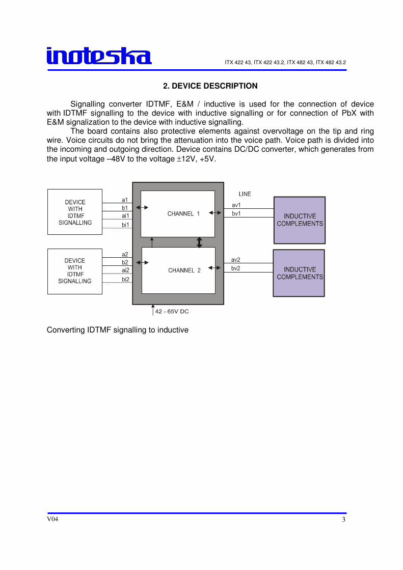
Signalling converter IDTMF, E&M / inductive is used for the connection of device with IDTMF signalling to the device with inductive signalling or for connection of PbX with E&M signalization to the device with inductive signalling. The board contains also protective elements against overvoltage on the tip and ring wire. Voice circuits do not bring the attenuation into the voice path. Voice path is divided into the incoming and outgoing direction. Device contains DC/DC converter, which generates from
the input voltage –48V to the voltage ±12V, +5V.
Converting IDTMF signalling to inductive
ITX 422 43, ITX 422 43.2, ITX 482 43, ITX 482 43.2
V04 4
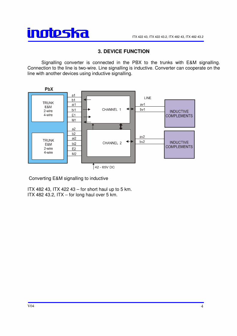
3. DEVICE FUNCTION
Signalling converter is connected in the PBX to the trunks with E&M signalling. Connection to the line is two-wire. Line signalling is inductive. Converter can cooperate on the line with another devices using inductive signalling.
Converting E&M signalling to inductive ITX 482 43, ITX 422 43 – for short haul up to 5 km. ITX 482 43.2, ITX – for long haul over 5 km.
ITX 422 43, ITX 422 43.2, ITX 482 43, ITX 482 43.2
V04 5
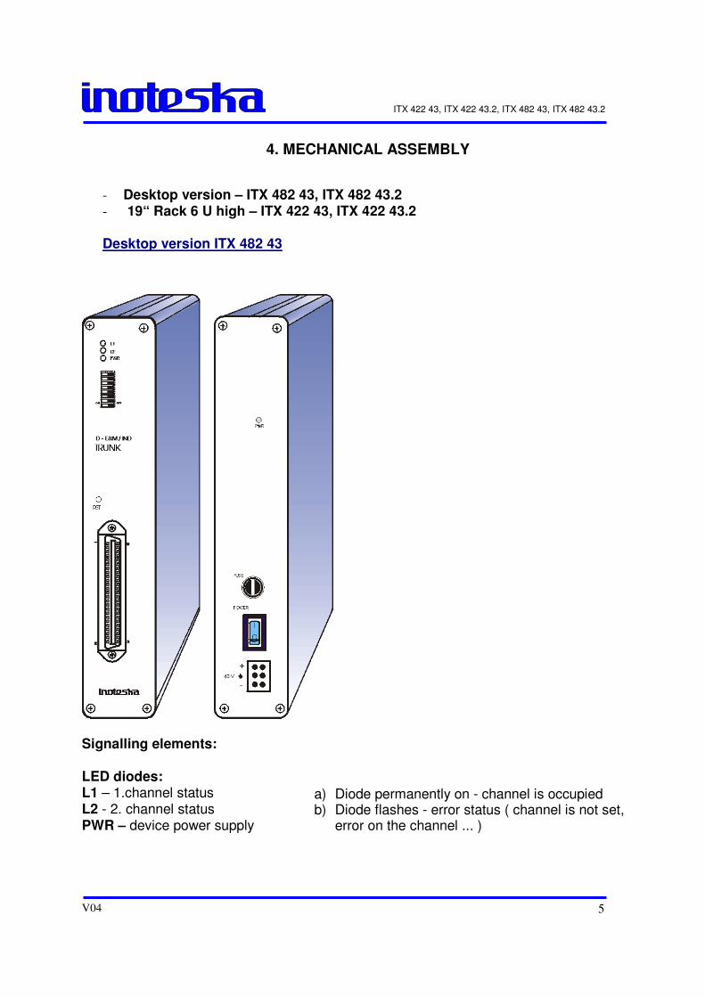
4. MECHANICAL ASSEMBLY
- Desktop version – ITX 482 43, ITX 482 43.2 - 19“ Rack 6 U high – ITX 422 43, ITX 422 43.2 Desktop version ITX 482 43
Signalling elements: LED diodes: L1 – 1.channel status L2 - 2. channel status PWR – device power supply
a) Diode permanently on - channel is occupied b) Diode flashes - error status ( channel is not set,
error on the channel ... )
ITX 422 43, ITX 422 43.2, ITX 482 43, ITX 482 43.2
V04 6
Switches on the front panel SW 2: 1 - E&M signalling 0 - pulse 1 - permanent 2 - Signalling 0 - IDTMF 1 - E&M 3 – Seizure/release confirmation 0 – without confirmation 1 – with confirmation 4 - Unused 5 – Dial to the line 0 - DTMF 1 - pulse 6 – Dial to the PbX 0 - DTMF 1 - pulse 7 - Diagnostics 0 - no 1 - yes 8 - Status 0 – SLAVE (Controlled) 1 – MASTER (Controlling) 0 – OFF
1 – ON
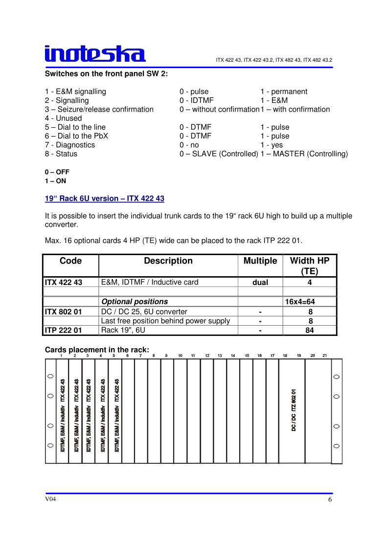
19“ Rack 6U version – ITX 422 43 It is possible to insert the individual trunk cards to the 19“ rack 6U high to build up a multiple converter.
Max. 16 optional cards 4 HP (TE) wide can be placed to the rack ITP 222 01.
Code Description Multiple Width HP (TE)
ITX 422 43 E&M, IDTMF / Inductive card dual 4
Optional positions 16x4=64
ITX 802 01 DC / DC 25, 6U converter - 8
Last free position behind power supply - 8
ITP 222 01 Rack 19", 6U - 84
Cards placement in the rack:
ITX 422 43, ITX 422 43.2, ITX 482 43, ITX 482 43.2
V04 7
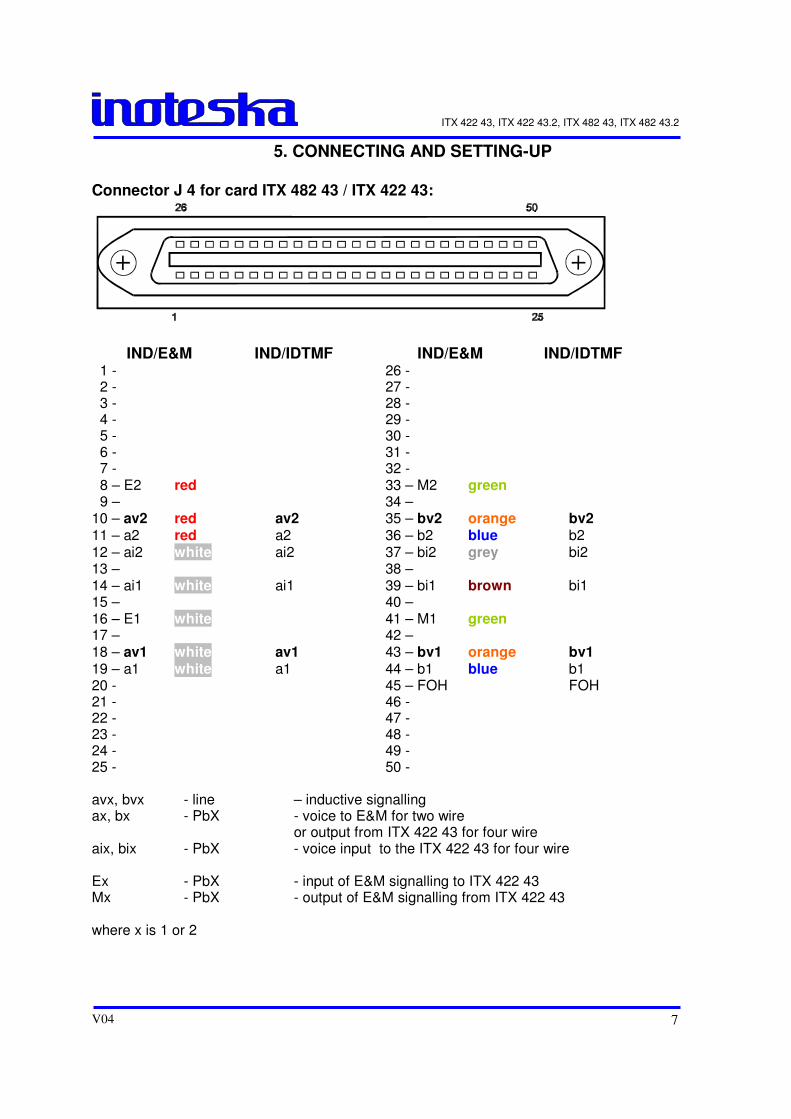
5. CONNECTING AND SETTING-UP
Connector J 4 for card ITX 482 43 / ITX 422 43:
IND/E&M IND/IDTMF IND/E&M IND/IDTMF 1 - 26 - 2 - 27 - 3 - 28 - 4 - 29 - 5 - 30 - 6 - 31 - 7 - 32 - 8 – E2 red 33 – M2 green 9 – 34 – 10 – av2 red av2 35 – bv2 orange bv2 11 – a2 red a2 36 – b2 blue b2 12 – ai2 white ai2 37 – bi2 grey bi2 13 – 38 – 14 – ai1 white ai1 39 – bi1 brown bi1 15 – 40 – 16 – E1 white 41 – M1 green 17 – 42 – 18 – av1 white av1 43 – bv1 orange bv1 19 – a1 white a1 44 – b1 blue b1 20 - 45 – FOH FOH 21 - 46 - 22 - 47 - 23 - 48 - 24 - 49 - 25 - 50 - avx, bvx - line – inductive signalling ax, bx - PbX - voice to E&M for two wire or output from ITX 422 43 for four wire aix, bix - PbX - voice input to the ITX 422 43 for four wire Ex - PbX - input of E&M signalling to ITX 422 43 Mx - PbX - output of E&M signalling from ITX 422 43 where x is 1 or 2
ITX 422 43, ITX 422 43.2, ITX 482 43, ITX 482 43.2
V04 8
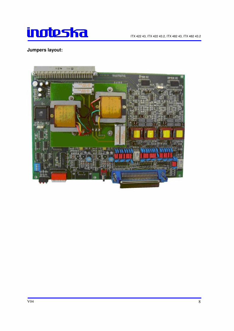
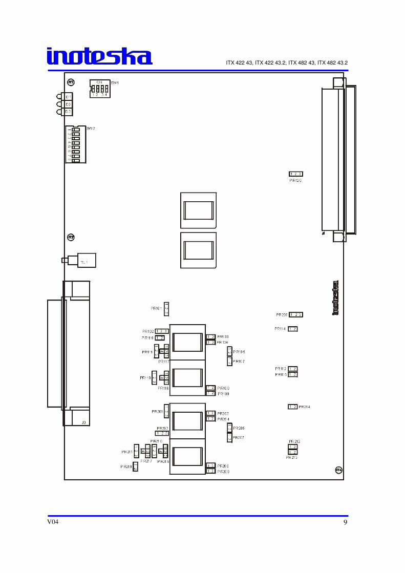
Jumpers layout:
ITX 422 43, ITX 422 43.2, ITX 482 43, ITX 482 43.2
V04 9
ITX 422 43, ITX 422 43.2, ITX 482 43, ITX 482 43.2
V04 10
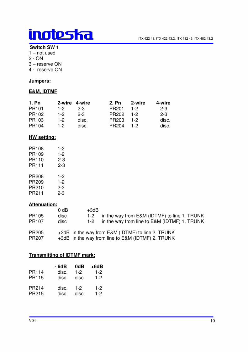
Switch SW 1 1 – not used 2 - ON 3 – reserve ON 4 - reserve ON Jumpers:
E&M, IDTMF
1. Pn 2-wire 4-wire 2. Pn 2-wire 4-wire PR101 1-2 2-3 PR201 1-2 2-3 PR102 1-2 2-3 PR202 1-2 2-3 PR103 1-2 disc. PR203 1-2 disc. PR104 1-2 disc. PR204 1-2 disc. HW setting: PR108 1-2 PR109 1-2 PR110 2-3 PR111 2-3 PR208 1-2 PR209 1-2 PR210 2-3 PR211 2-3 Attenuation: 0 dB +3dB PR105 disc 1-2 in the way from E&M (IDTMF) to line 1. TRUNK PR107 disc 1-2 in the way from line to E&M (IDTMF) 1. TRUNK PR205 +3dB in the way from E&M (IDTMF) to line 2. TRUNK PR207 +3dB in the way from line to E&M (IDTMF) 2. TRUNK Transmitting of IDTMF mark: - 6dB 0dB +6dB PR114 disc. 1-2 1-2 PR115 disc. disc. 1-2
PR214 disc. 1-2 1-2 PR215 disc. disc. 1-2
ITX 422 43, ITX 422 43.2, ITX 482 43, ITX 482 43.2
V04 11
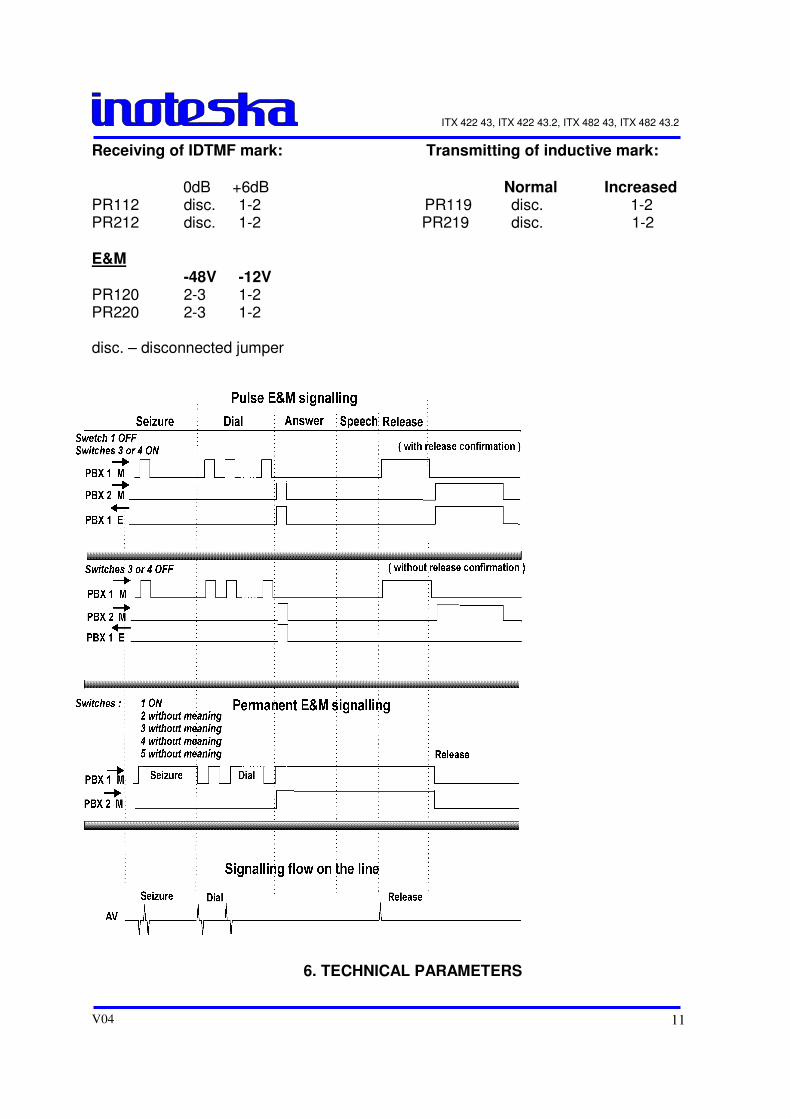
Receiving of IDTMF mark: Transmitting of inductive mark: 0dB +6dB Normal Increased PR112 disc. 1-2 PR119 disc. 1-2 PR212 disc. 1-2 PR219 disc. 1-2 E&M -48V -12V PR120 2-3 1-2 PR220 2-3 1-2 disc. – disconnected jumper
6. TECHNICAL PARAMETERS
ITX 422 43, ITX 422 43.2, ITX 482 43, ITX 482 43.2
V04 12
Power supply requirements: - -40V to -64V DC, - input current less than 0,3A
Pulse E & M signalling timing: Seizure: 150 ms or 70 ms Release: 600 ms Dial: impulse - 60 ms, pulse spacing - 40 ms Transmission parameters: Inserted attenuation Value of the inserted attenuation (measured by the frequency 800 Hz and input level of signal 0dB) is 0,5dB + - 0,7dB. Asymmetry attenuation Asymmetry attenuation is better than the values stated below. 50 - 300 Hz 26 dB 300 - 600 Hz 40 dB 600 - 3400 Hz 46 dB Reflection attenuation Reflection attenuation is higher than 12 dB in the range of 300 - 600 Hz and 18dB in the range of 600 - 3400 Hz, by the input level 0 dB. Psophometric noise Average value of the psophometric noise (measured in the point with the zero relative level of the voice signal) does not exceed the value of -67 dB. Signalling marks and dial Transmitter: Transmitting marks have the max. level 140 V. Receiver: Evaluates the marks on the line from the level 8V.
7. CONVERTER DC / DC
ITX 422 43, ITX 422 43.2, ITX 482 43, ITX 482 43.2
V04 13
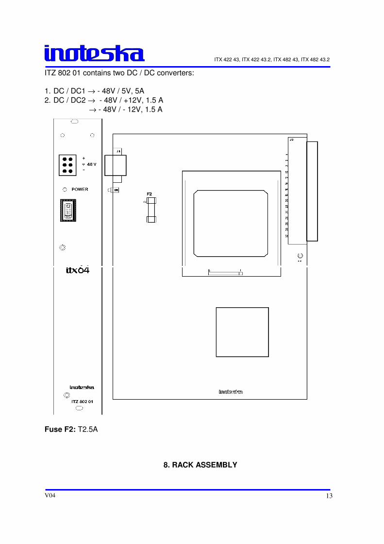
ITZ 802 01 contains two DC / DC converters:
1. DC / DC1 → - 48V / 5V, 5A
2. DC / DC2 → - 48V / +12V, 1.5 A
→ - 48V / - 12V, 1.5 A
Fuse F2: T2.5A
8. RACK ASSEMBLY
ITX 422 43, ITX 422 43.2, ITX 482 43, ITX 482 43.2
V04 14
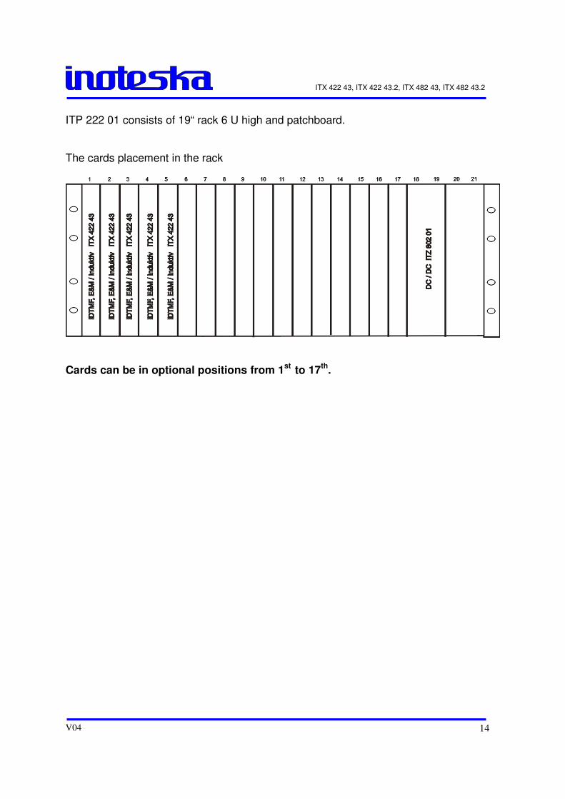
ITP 222 01 consists of 19“ rack 6 U high and patchboard. The cards placement in the rack
Cards can be in optional positions from 1
st to 17
th.