convex integrated tape channel subsystem (1tc4000 ... diag doc... · convex integrated tape channel...
TRANSCRIPT

CONVEX Integrated Tape Channel Subsystem (1tc4000) Diagnostics Manual
Order No. DHW-285
First Edition March 1992
CONVEX Press Richardson, Texas
United States of America
CONVEX Integrated Tape Channel Subayatem (1t.c4000) Diagnoatica Manual
Order No. DHW-285 First Edition
Copyright © 1992 CONVEX Computer Corporation All rights reserved.
This document is copyrighted. This document may not, in whole or part, be copied, duplicated, reproduced, translated, electronically stored or reduced to machine readable Corm without prior written consent Crom CONVEX Computer Corporation (CONVEX).
Although the material contained herein has been carefully reviewed, CONVEX does not warrant it to be Cree of errors or omissions. CONVEX reserves the right to make corrections, updates, revisions, or changes to the inCormation contained herein. CONVEX does not warrant the material described herein to be Cree of patent infringement. ~
UNLESS PROVIDED OTHERWISE IN WRITING WITH CONVEX COMPUTER CORPORATION (CONVEX), THE EQUIPMENT DESCRIBED HEREIN IS PROVIDED "AS IS" WITHOUT WARRANTY OF ANY KIND, EITHER EXPRESSED OR IMPLIED, INCLUDING, BUT NOT LIMITED TO, THE IMPLIED WARRANTIES OF MERCHANTABILITY AND FITNESS FOR A PARTICULAR PURPOSE. SOME STATES DO NOT ALLOW THE EXCLUSION OF IMPLIED WARRANTIES. THE ABOVE EXCLUSION MAY NOT BE APPLICABLE TO ALL PURCHASERS BECAUSE WARRANTY RIGHTS CAN VARY FROM STATE TO STATE. IN NO EVENT WILL CONVEX BE LIABLE TO ANYONE FOR SPECIAL, COLLATERAL, INCIDENTAL, OR CONSEQUENTIAL DAMAGES, INCLUDING ANY LOST PROFITS OR LOST SA VIN GS, ARISING OUT OF THE USE OR INABILITY TO USE THIS EQUIPMENT. CONVEX WILL NOT BE LIABLE EVEN IF IT HAS BEEN NOTIFIED OF THE POSSIBILITY OF SUCH DAMAGE BY THE PURCHASER OR ANY THIRD PARTY.
CONVEX and the CONVEX logo ("C") are registered trademarks or CONVEX Computer Corporation. ConvexOS, C3400, C3800, and the C200 Series are trademarks or CONVEX Computer Corporation.
UNIX is a registered trademark or UNIX System Laboratories, Inc.
Printed in the United States of America

Edition
First
Revision history
CONVEX Integrated Tape Channel Subsystem (1 tc4000) Diagnostics Manual
Document No. Date Description
760-004730-000 March 1992 First release.

THIS PAGE INTENTIONALLY LEFT BLANK

Table of Contents
1 Diagnostics environment 1.1 Overview .............................................................................................................................................................................. 1-1
1.2 dshell utility overview ...................................................................................................................................................... 1-1
1.2.1 Diagnostic shell (dshell) overview ........................................................................................................................... 1-1
1.2.2 dshell commands ..................................................................................................................................................... 1-2
1.2.3 Syntax help for dshell commands ........................................................................................................................... 1-3
2 Integrated tape channel subsystem test (1 tc4000) 2.1 Overview .............................................................................................................................................................................. 2-1
2.2 Required equipment ............................................................................................................................................................. 2-2
2.3 Test invocation .................................................................................................................................................................... 2-3
2.4 Initialization sequence for 1 t.c4000 ................................................................................................................................... 2-4
2.5 Test parameter menu .......................................................................................................................................................... 2-4
2.5.1 Prompt explanations ................................................................................................................................................... 2-6
2.5.2 Test parameter summary ........................................................................................................................................... 2-8
2.6 Class descriptions ................................................................................................................................................................. 2-8
2.7 Class 0 subtests .................................................................................................................................................................... 2-9
2.7.1 Subtest 1, board reset test ........................................................................................................................................ 2-11
2.7.2 Subtest 2, slot verification test ................................................................................................................................. 2-12 2.7.3 Subtest 100, data RAM bit functionality test .......................................................................................................... 2-12
2.7.4 Subtest 110, data RAM column functionality test ................................................................................................... 2-12
2.7.5 Subtest 120, data RAM uniquene55 test ................................................................................................................... 2-12
2.7.6 Subtest 130, data RAM parity test .......................................................................................................................... 2-12
2.7.7 Subtest 200, instruction RAM bit functionality test ................................................................................................ 2·12
2.7.8 Subtest 210, instruction RAM column functionality test ........................................................................................ 2-12
2.7.9 Subtest 220, instruction RAM uniqueness test ......................................................................................................... 2-13
2.7.10 Subtest 230, instruction RAM parity test .............................................................................................................. 2-13
2.7.11 Subtest 240, instruction RAM execution test ....................................................................................................... 2-13
2.7.12 Subtest 300, PMAP RAM bit functionality test .................................................................................................... 2-13
2.7.13 Subtest 310, PMAP RAM column functionality test ............................................................................................. 2-13
2.7.14 Subtest 320, PMAP RAM uniqueness test ............................................................................................................. 2-13
2.7.15 Subtest 330, PMAP RAM parity test ..................................................................................................................... 2-13
2.7.16 Subtest 400, PBUS header generation test ............................................................................................................. 2-14
2.7.17 Subtest 410, PBUS access test ................................................................................................................................ 2-14
2.7.18 Subtests 500, 510, 520, and 530 (data buffer bit functionality tests) .................................................................... 2-14
2.7.19 Subtests 501, 511, 521, and 531 (data buffer column functionality tests) ............................................................. 2-15
2.7.20 Subtests 502, 512, 522, and 532 (data buffer uniqueness tests) ............................................................................. 2-15
2.7.21 Subtests 503, 513, 523, and 533 (data buffer parity tests) ..................................................................................... 2-15
2.7.22 Subtests 604, 614, 616, and 618 (DPED coh1mn functionality tests) ..................................................................... 2-16
2.7.23 Subtests 605, 615, 617, and 619 (DPED parity tests) ............................................................................................ 2-16
2.7.24 Subtest 620, data buffer all ports uniqueness test .................................................................................................. 2-17
2.7.25 Subtests 630, 640, 650, and 660 (DICE bit functionality tests) ............................................................................. 2-17
2.7.26 Subtests 631, 641, 651, and 661 (DICE column functionality tests) ...................................................................... 2-17
2.7.?:1 Subtests 632, 642, 652, and 662 (DICE uniqueness tests) ...................................................................................... 2-18
2.7.28 Subtests 633, 643, 653, and 663 (DICE parity tests) ............................................................................................. 2-18
2.7.29 Subtest 700, PIGA bit functionality test ................................................................................................................ 2-19
2.7.30 Subtest 701, PIGA column functionality test ......................................................................................................... 2-19
Subtest 702, PIGA uniqueness test ......................................................................................................................... 2-19
Subtest 800, data RAM protection test .................................................................................................................. 2-19 ~ 2.7.31
2.7.32
v

2.7.33 Subtest 900, EEPROM write protection test ....................•.....•..................................................................•.........•. 2-19
2.8 Class 1 subtests •.•..•...•.••...........••..••...................•....................•..•..................................................................•.......•...........•. 2-19
2.8.1 Subtests 1000, 1010, 1020, and 1030 (cha.nnel-to-memory da.ta. pa.th tests) ..........•..........................................•...•. 2-20
2.8.2 Subtest& 1100, 1110, 1120, a.nd 1130 (memory-to-cha.nnel da.ta. pa.th tests) ........................•...................•....•••..•...• 2-21
2.8.3 Subtest& 1200, 1210, 1220, a.nd 1230 (cha.nnel-to-memory bounda.ry tests) ..................................•..........•..•....••.•..• 2-21
2.8.4 Subtest& 1300, 1310, 1320, a.nd 1330 (memory-to-cha.nnel bounda.ry tests) ..........................•...............•...•....••....••. 2-22
2.8.5 Subtest& 1400, 1410, 1420, a.nd 1430 (a.lignment tests) ............................................•...........................•...•.•..•.•........ 2-22
2.8.6 Subtest& 1500, 1510, 1520, and 1530 (a.rbiter tests) ................•.....................•...............................•...•...................... 2-23
2.9 Class 2 subtest&, manufacturing support boa.rd tests ....................................................................................................... 2-23
2.9.1 Subtest 2000, transceiver bus A/bus B bit functionality test .................................................................................. 2-24
2.9.2 Subtest 2010, tra.nsceiver control signa.ls bit functionality test ............................................................................... 2-24
2.10 Class 4 subtests, ta.pe motion read/write device tests .................................................................................................... 2-24
2.10.1 Subtest 4000, ta.pe mark test ..........•.•..................................................................................................................... 2-25
2.10.2 Subtest 4010, space record test ...............................................................................................•.............................. 2-25
2.10.3 Subtest 4030, long block read test ......•.....•...................•.........................•.......................................................•....... 2-25
2.10.4 Subtest 4040, fixed record size read/write test ...................................................................................................... 2-26 2.10.5 Subtest 4050, write Ille UNIX-style test ................................................................................................................. 2-26
2.11 Class 5 subtest&, tape drive exception tests .................................................................................................................... 2-27
2.11.1 Subtest 5000, beginning-of-tape (BOT) sta.tus exception test ...............................................................................• 2-27
2.11.2 Subtest 5010, zero-length operations exception test ..........................................................................•................... 2-27
2.11.3 Subtest 5020, end-of-da.ta. (EOD) status exception test ......................................................................................... 2-28 2.12 Interactive comma.nds .•..•.................................................................................................................................•............... 2-28
2.12.1 I ............................................................................................................................................................................... 2-29
2.12.2 banner ................................................................................................................................................................... 2-29
2.12.3 base ........................................................................................................................................................................ 2-30
2.12.4 -c ............................................................................................................................................................................ 2-31 ~'
2.12.5 debug ...................................................................................................................................................................... 2-32
2.12.6 flags ...................................................................................................................................................................... 2-32
2.12.7 help ........................................................................................................................................................................ 2-33
2.12.8 1n1 t. ........................................................................................................................................................................ 2-33
2.12.9 log .......................................................................................................................................................................... 2-33
2.12.10 man ........................................................................................................................................................................ 2-34
2.12.11 Prt. _err ............................................................................................................................................................... 2-34
2.12.12 quit. ...................................................................................................................................................................... 2-34
2.12.13 -s ·········································································································································································· 2-35 2.12.14 save ...................................................................................................................................................................... 2-35
2.12.15 set. ........................................................................................................................................................................ 2-35
2.12.16 st.at.e .................................................................................................................................................................... 2-38
2.12.17 t.race .................................................................................................................................................................... 2-38
2.12.18 t.rout. .................................................................................................................................................................... 2-39
2.13 Interactive debugger ....••...•..................................................................................................................••...................•...... 2-39
2.14 Interactive debugger comma.nd descriptions .................................................................................•..............................•.. 2-41
2.14.1 help ........................................................................................................................................................................ 2-41
2.14.2 ? ............................................................................................................................................................................... 2-41
2.14.3 block .....................•................................................................................................................................................ 2-41
2.14.4 bsf .......................................................................................................................................................................... 2-41
2.14.5 bsr .......................................................................................................................................................................... 2-42
2.14.6 Cd ............................................................................................................................................................................ 2-42
2.14.7 connect. ................................................................................................................................................................. 2-42
2.14.8 echo ........................................................................................................................................................................ 2-42
2.14.9 fb, fl, fv ............................................................................................................................................................. 2-42
2.14.10 ffb. ffl. ffv .................................................................................................................................................... 2-43
2.14.11 fsf ........................................................................................................................................................................ 2-43
vi

(~
2.14.12 fsr ........................................................................................................................................................................ 2-44
2.14.13 identify ............................................................................................................................................................. 2-44
2.14.14 iu .......................................................................................................................................................................... 2-44
2.14.15 mb, mw. ml ........................................................................................................................................................... 2-44
2.14.16 mmb. mmw, mml .................................................................................................................................................... 2-45
2.14.17 pause .................................................................................................................................................................... 2-46
2.14.18 quit ...................................................................................................................................................................... 2-46
2.14.19 rewind .................................................................................................................................................................. 2-46
2.14.20 rphys .................................................................................................................................................................... 2-46
2.14.21 status .................................................................................................................................................................. 2-46
2.14.22 uni tclr ............................................................................................................................................................... 2-46
2.14.23 unload .................................................................................................................................................................. 2-46
2.14.24 weof ...................................................................................................................................................................... 2-46
2.14.25 wphys .................................................................................................................................................................... 2-47
List of Tables
1-1 dshell commands ................................................................................................................................................................. 1-2 2-1 Hardware requirements .......................................................................................................................................................... 2-2
2-2 test command options .......................................................................................................................................................... 2-3
2-3 Getting help during test parameter entry ............................................................................................................................. 2-5
2-4 i tc4000 test classes .............................................................................................................................................................. 2-9
2-5 Class 0 subtests ..................................................................................................................................................................... 2-10
(-., 2-6 2-7
Class 0 data pattern ............................................................................................................................................................. 2-11
Data buffer bit functionality subtests ................................................................................................................................... 2-14
2-8 Data. buffer column functionality subtests ........................................................................................................................... 2-15
2-9 Data buffer uniqueness subtests ............................................................................................................................................ 2-15
2-10 Da.ta. buffer parity subtests ................................................................................................................................................. 2-16
2-11 DPED column functionality subtests .................................................................................................................................. 2-16
2-12 DPED parity subtests ......................................................................................................................................................... 2-17
2-13 DICE bit functionality subtests .......................................................................................................................................... 2-17
2-14 DICE column functionality subtests ................................................................................................................................... 2-18
2-15 DICE uniqueness subtests ................................................................................................................................................... 2-18
2-16 DICE parity subtests .......................................................................................................................................................... 2-19
2-17 Class 1 subtests ................................................................................................................................................................... 2-20
2-18 Channel-to-memory data path subtests ............................................................................................................................. 2-21
2-19 Memory-to-channel da.ta pa.th subtests .............................................................................................................................. 2-21
2-20 Channel-to-memory boundary subtests .............................................................................................................................. 2-22
2-21 Memory-to-channel boundary subtests ............................................................................................................................... 2-22
2-22 Alignment subtests .............................................................................................................................................................. 2-22
2-23 Arbiter subtests ................................................................................................................................................................... 2-23
2-24 Class 2 subtests ................................................................................................................................................................... 2-24
2-25 Cla.ss 4 subtests ...............................................................................................................................................•................... 2-25
2-26 Subtest 4040 da.ta. pa.ttern .................................................................................................................................................. 2-26
2-27 Cla.ss 5 subtests ................................................................................................................................................................... 2-27
2-28 Interactive commands ......................................................................................................................................................... 2-28
2-29 Settable constant values ..................................................................................................................................................... 2-37
vii
List of Figures
1-1 Syntax help tor the loop command ...................................................................................................................................... 1-3
2-1 Initial teat invocation sequence .............................................................................................................................................. 2-3
2-2 Test paramet.er menu ............................................................................................................................................................. 2-5 2-3 Sample teat paramet.er aammary ........................................................................................................................................... 2-8 2-4 Int.eractive debugger online help .......................................................................................................................................... 2-40
viii

Preface
Purpose and intended audience
This manual explains how to run the 1 tc4000 diagnostic, which verifies the operation of an integrated tape channel (ITC). This document is not a tutorial, but rather a reference for the users of the 1 tc4000 diagnostics, including field service and manufacturing test personnel, as well as the diagnostics sustaining staff. In addition, CONVEX customers can use this manual to execute the 1 tc4000 diagnostic.
This document is intended for:
• CONVEX customer support engineers and CONVEX manufacturing personnel
• Customers who install or maintain their own CONVEX supercomputer systems
Organization
This document consists of the following:
• Chapter 1, "Diagnostics environment"-lntroduces theories and concepts that underlie diagnostics on CONVEX machines and provides an overview of the operating system and dshell utility used by the diagnostic tests.
• Chapter 2, "Integrated tape channel subsystem test (1 tc4000)"-Describes how to operate the diagnostic, including prerequisites, test invocation, internal initialization sequence, and class descriptions. It also describes interactive commands and the interactive debugger.
CONVEX ITC Diagnostics Manual ix

Notational Conventions
x
Notational conventions are systems of characters, symbols, terms, or abbreviated expressions used to express technical Cacts or quantities as established by this guide. The following notational conventions are used in this document:
• Boldface indicates user-entered information for a computer program that should be entered exactly as it appears.
• Italic is used to define new terms, for user-supplied variables, for emphasis, and to indicate titles of publications.
• Constant-width is used for code examples, command names and options, error messages, screen output, and system calls.
• C:=J indicates a specific keyboard key to press. A hyphen between two keycap symbols indicates to press the two keys simultaneously. A space between two symbols indicates a sequence of keys to press.
• Bit numbering is left to right, N-1 through 0. The most significant numerical bit is N-1, the least significant 0. The bit numbering represents the binary weight of a position.
• Bit fields are specified using the following convention: name<z .. y> where the bit field is name from bits z through y.
• Individual bit positions within a register are denoted by specific positions separated by commas. For example, REG<15,4,0> denotes bits 15, 4, and 0 of REG.
• Byte numbering is from left to right.
• A bit is a single binary value or entity.
• A nibble is 4 bits.
• A byte is 8 bits.
• A halfword is 16 bits.
• A word is 32 bits.
• A longword is 64 bits.
• An inatruction is a multihalfword operand.
• A bit is act when it contains a binary value of 1.
• A bit is clear when it contains a binary value of 0.
• All memory and 1/0 addresses are written in hexadecimal notation unless explicitly stated otherwise.
• All register contents are written in hexadecimal notation unless explicitly stated otherwise.
• A regiater is a programmer-visible hardware storage element internal to the processor.
• Phyaical memory is the physical storage installed in the processor
• The symbol K is an abbreviation for kilo or 1,024.
• The symbol Mis an abbreviation for mega or 1,048,576.
• The symbol G is an abbreviation for giga or 1,073,741,824.
• Reaerved or undefined convey what to expect, if anything, from unused fields in registers, reserved memory, or reserved 1/0 space. Algorithm implementation based on the use of undefined_ or reserved fields is not recommended.
CONVEX ITC Diagnostics Manual
~ 1 Warnings
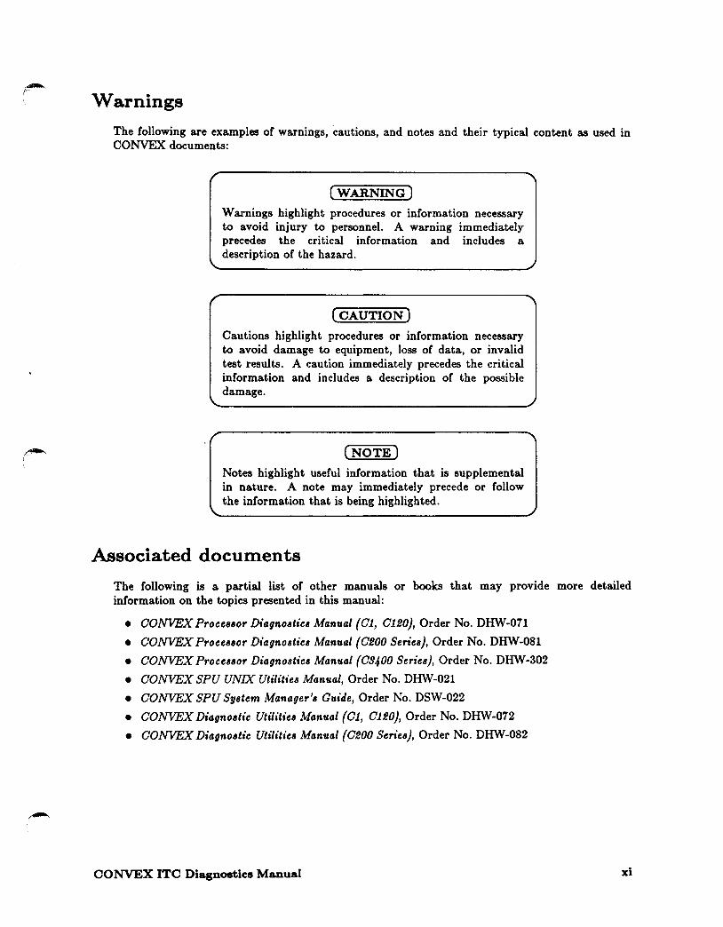
The following are examples of warnings, cautions, and notes and their typical content as used in CONVEX documents:
(WARNING)
Warnings highlight procedures or information necessary to avoid injury to personnel. A warning immediately precedes the critical information and includes a description of the hazard.
(CAUTION)
Cautions highlight procedures or information necessary to avoid damage to equipment, loss of data, or invalid test results. A caution immediately precedes the critical information and includes a description of the possible damage.
(NOTE)
Notes highlight useful information that is supplemental in nature. A note may immediately precede or follow the information that is being highlighted .
.Associated documents
The following is a partial list of other manuals or books that may provide more detailed information on the topics presented in this manual:
• CONVEX Proceaaor Diagnoatics Manual {Cl, C120}, Order No. DHW-071
• CONVEX Proceaaor Diagnoatics Manual {C200 Series}, Order No. DHW-081
• CONVEX Proceaaor Diagnoatics Manual {C9400 Series}, Order No. DHW-302
• CONVEX SPU UNIX Utilities Manual, Order No. DHW-021
• CONVEX SPU Syatem Manager'a Guide, Order No. DSW-022
• CONVEX Diagnostic Utilitiea Manual {Cl, C120}, Order No. DHW-072
• CONVEX Diagnostic Utilitiea Manual {C200 Seriea), Order No. DHW-082
CONVEX ITC Diagnostics Manual xi

Ordering documents
To order the most current version or this or any other CONVEX document, send requests to:
CONVEX Computer Corporation Customer Service PO Box 833851 Richardson TX 75083-3851 USA
Include the order number with the request. The order number is on the title page of the manual and begins with the letters "DSW" or "DHW."
Technical assistance
Hardware, software and documentation support can be obtained through the CONVEX Technical Assistance Center (TAC):
• From all locations in the continental United States, call 1(800)952-0379.
• From locations in Canada, call 1(800)345-2384.
• From all other locations, contact the nearest CONVEX office.
Using the contact utility
xii
The TAC recommends using the contact utility to report a hardware, software, or documentation problem. The contact utility is an interactive program that helps the TAC track reports and route them to the CONVEX personnel most qualified to fix a problem. After you invoke contact, it prompts you for information about the problem. When you finish your report, contact mails it to the TAC electronically
The TAC notifies you within 48 hours that your report has been received. To use contact requires:
• UNIX-to-UNIX Communications Protocol (UUCP) connection to the TAC.
• Full path name of the program or utility in question.
• Version number of the program or utility in question.
Refer to the contact(!) man page for complete details.
CONVEX ITC Diagnostics Manual
~ I

Acknowledgments
I would like to thank the following people for their contributions to this manual:
• Technical contributor: Alex Chan
• Document review team: Martin Mennig, Kris Meier
• Editorial Services: Sheri Roloff
This document would not have been possible without their help.
Cari Tuttle
CONVEX I/O Documentation
CONVEX ITC Diagnostics Manual xiii

THIS PAGE INTENTIONALLY LEFT BLANK
xiv CONVEX ITC Diagnostics Manual

Chapter 1 Diagnostics environment
1.1 Overview
CONVEX system diagnostics consist of a suite of test programs designed (except where noted) to execute under the service processor operating system, SPU OS. These programs utilize the capabilities of the service processor to test the operation of one or more of the functions of the system and report any errors detected. All diagnostics in this manual are intended to be executed "offiine," that is, while ConvexOS is not being executed by any of the central processing units (CPUs) in the system.
The service processor, together with SPU OS, various diagnostic utilities, and the test programs themselves, comprise the CONVEX diagnostic environment. This chapter provides an overview of the operating system and dshell utility used by the diagnostic tests. For more information about the diagnostic environment, refer to the CONVEX Processor Diagnostics Manual {C1, C120}, CONVEX Processor Diagnostics Manual {C200 Series}, or CONVEX Processor Diagnostics Manual {C9400 Series}, depending on the architecture of the machine under test.
~ 1.2 dshell utility overview
The diagnostic shell (dshell) is a command interface program that runs on the service processor. Most of the diagnostics available for the CONVEX machines are interfaced through the dshell. Certain peripheral diagnostics are run as standalone tests. This section provides a brief 9verview of the dshell utility, including a brief explanation of the utility and a list of the utility's commands. For a complete description of the dshell utility, refer to the Oshell chapter of the CONVEX Diagnostic Utilities Manual {C200 Series).
1.2.1 Diagnostic shell (dshell) overview
The dshell has two functions:
• Selecting diagnostics for execution
• Selecting test options as listed:
- Pause on a failure or at the beginning or end of any specific subtest
- Loop on a specific type of subtest or on a given set of subtests
- Select subtest execution order
- Direct test output to a file or to the screen (or both) to monitor the test
- Select long or short error messages, or turn messages off
- Execute either user-created or predefined command scripts
CONVEX ITC Diagnostics Manual 1-1

1.2.2 dshell commands
Table 1-1 summarizes the various dshell commands and their functions.
Table 1-1, dshell commands
Command Function
I [commondj Accesses or rorks a SPU OS shell to execute the command that rollows I .
extt. Immediately terminates the dsbell or process and any test processes that may qult. have been forked.
(CTRL-C) Returns user to the dsbell command level if no subtest is running. Ir subtest is running, provides options to continue or abort subtest.
(CTRL-B) Immediately terminates the dsbell and any associated active processes. Core is dumped.
help Displays a standard help menu. The menu describes the correct command syntax for each dshell command and gives a terse description of what each command does.
st.at.us Generates a report on the current state of the dshell command options. This report gives the name of each option, its current value, and an explanation of its current effect.
log [options! Provides a mechanism for specirying the number or failures allowed to occur berore a test or subtest terminates execution.
loop [options! Causes dshell to repeat the execution of a test or subtest.
msgs [options! Enables or disables different levels or test, class, and subtest result messages.
pause [options! jnnl Returns program control to the dshell at the beginning, end, or railure or all or specific subtests.
t.est. [ testnome] [options] I Executes specific tests and displays test, class, and subtest menus.
1-2 CONVEX ITC Diagnostics Manual

~· I
1.2.3 Syntax help for dshell commands
The syntax for each dshell command can be obtained by typing the command without options and pressing(RETURN). For example, by typing loop and pressing(RETURNJ, the syntax help in Figure 1-1 will be displayed on the screen.
Figure 1-1, Syntax help for the loop command
I loop Proper syntax is:
loop off (-s) C-t) :disables loop modes loop -s nnn :loop on subtest nnn loop -t :loop on test
CONVEX ITC Diagnostics Manual 1-3

~'
THIS PAGE INTENTIONALLY LEFT BLANK
1-4 CONVEX ITC Diagnostics Manual

2.1
Chapter 2 Integrated tape channel subsystem test
(1 tc4000)
Overview
1 tc4000 is a diagnostic test suite for the CONVEX integrated tape channel (ITC) subsystem. This diagnostic supports the E-MASS data storage system. The ITC subsystem consists of:
• ITC IPI-3 interface channel control unit (CCU)
• Internal cabling from the CCU to the CONVEX external IPl-3 connectors
• Downloaded CCU driver software
Specifically, 1 tc4000 accomplishes the following:
• Verifies that the ITC CCU is electrically sound in that its microprocessor can execute instructions from its ROM, access its data RAM, and access the PBUS.
• Verifies that the normal path CCU driver firmware can be downloaded, probe all ports, attach to all control units, and connect to all tape drives.
• Verifies that the normal path software can communicate with the E-MASS storage system and perform basic read, write, or verify tape operations.
• Verifies that the ITC subsystem is functional, reliable, and capable of supporting ConvexOS.
• Provides an interactive debugger that can execute commands from a script file.
CCU communications use the message-based system (MBS) used by ConvexOS. The intent is to test the communications paths used in a normal operating environment.
The itc.4000. t diagnostic is unique as a CONVEX diagnostic in two ways:
• It is a dedicated CCU diagnostic; it does not access a chassis controller such as a VMEbus SCSI controller.
• It attempts to address the diverse needs of its three primary users (manufacturing, development/integration, and field engineering).
The net result is a single diagnostic that encompasses board, device, system checkout, and interactive control tests in one object body. This combined diagnostic can be invoked from the diagnostic shell (dshell), as a standalone test, or in an interactive mode.
CONVEX ITC Diagnostics Manual 2-1

The three methods of invocation serve three purposes:
• For those users familiar with the dshell environment, operation of this diagnostic will be no different from any other dshell-compatible diagnostics. All dshell features, such as looping, test flags, and so on, are supported.
• For integration purposes the diagnostic can be executed in a standalone mode to get a go or no-go determination of the subsystem operation.
• Manufacturing personnel will find the control and logging features necessary to assist them in the production and debugging of the CCU.
2.2 Required equipment
2-2
Table 2-1 lists the required hardware for the ITC subsystem:
Table 2-1, Hardware requirements
C200 Series
Memory system 1
CPX SP2 or SP4 PIA or Pl2 Integrated Tape Channel subsystem
1 Memory system consists or a minimum of one pair of memory boards (one odd and one even).
Class 2 subtests require an external loopback cable or connector; these are standard cables and connectors that you must modify to run these tests.
The special external loopback cable is a regular IPI jumper cable (CONVEX Part Number 604-500007-001), to which you must make the following modifications:
BUSA bit 0-7 of end 1 BUSA parity of end 1 BUSB bit 0-7 of end 1 BUSB parity of end 1 DC Ground of end 1
connected to BUSB bit 0-7 of end 2 connected to BUSB parity of end 2 connected to BUSA bit 0-7 of end 2 connected to BUSA parity of end 2 connected to DC Ground of end 2
Other signal pins are disconnected.
The special external loop back connector is a regular IPI male connector, to which you must make the following modifications:
SELO connected to ATNI MASO connected to SL VI SYNO connected to SYNI
CONVEX ITC Diagnostics Manual

~ \ 2.3 Test invocation
The 1 tc4000 test executes under the diagnostic shell ( dshe 11) and supports all the features of the dshell. The dshell permits tests to be initiated in any order.
To invoke the 1 tc4000 test, use the procedure shown in Figure 2-L All responses in boldface are entered by the user.
(NOTE)
Use the following test invocation sequence for the initial invocation of 1 tc4000 or when the state of the machine is unknown. Also, the following invocation sequence should be used if any hard errors have occurred since the last system initialization.
Figure 2-1, Initial test invocation sequence
(spu) > cd /mnt/test (spu) > lnltall (spu)> dshell : test ltc4000 (-oplion) [ ••• ] J
(NOTE)
After entering dshell, specific dshell parameters may be changed. Refer to Chapter 2 in the CONVEX Diagnostic Utilitiea Manual {0200 Series} for more information.
Table 2-2 defines the options ([-option]) available for the test command.
Table 2-2, test command options
Option Description
-d Enter the debugger mode of the program without executing any subtests.
-f file Use an alternate parameter save file name. If this option is omitted, the parameter file used is /tmp/itc4000.tmp.
-1 Go to interactive mode only; no tests are executed.
-r script-filename Execute using commands from script file.
CONVEX ITC Diagnostics Manual 2-3

Entering only test itc4000 executes all 1tc4000 subtests sequentially. To execute one or more classes or individual subtests, use the -c or -s options during test invocation, respectively.
2.4 Initialization sequence for 1 tc4000
Once the test is invoked, the diagnostic determines if the test was invoked for quick startup with 1 tc4000x. If so, the diagnostic reads the test parameters from the specified parameter file (default parameter file is /tmp/itc4000.save). If not, the following actions are taken:
1. A list of prompts is displayed sequentially, allowing parameters to be set by the user or defaults accepted.
2. A TEST PARAMETER SUMMARY is displayed, listing all prompts and their responses.
3. Input parameters are written to the parameter file (default or user-specified).
4. The diagnostic downloads the CCU driver code (if necessary).
5. The diagnostic passes the current test parameters to the CCU driver.
6. If the -d option was not specified, the test code is started; otherwise, the test enters the interactive debugger.
The following sections describe these steps in more detail.
(NOTE)
The boot_db file (default /mnt/boot_db) determines what CCU and memory are installed. If this file is nonexistent, it can be created from the (spu) > prompt with the command scn_util -b > /mnt/boot_db.
2.5 Test parameter menu
2-4
If not invoked with 1 tc4000x, the diagnostic displays test parameter prompts sequentially, allowing selection of default test parameters or specification of different values. Figure 2-2 shows all prompts, their possible answers in brackets [ J, and their default answers in parentheses ( ). The prompts and responses in the figure appear sequentially on the screen, one line at a time. The figure illustrates all questions that can be displayed during test parameter input; however, some questions may be omitted, depending on answers to previous questions. In all cases, questions are numbered sequentially.
CONVEX ITC Diagnostics Manual
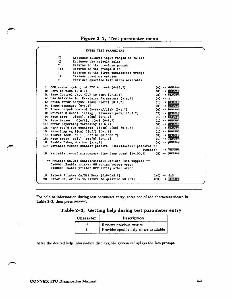
Figure 2-2, Test parameter menu
ENTER TEST PARAMETERS
[] Encloses alloved input ranges or values () Encloses the default value
Returns to the previous prompt :nn Returns to the prompt # nn
Returns to the first unsatisfied prompt :? Revievs previous entries ? Provides specific help vhere available
1: CCU number (slot) of ITC to test [0-16,?] 2: Port to test [0-3,?] 3: Tape Control Unit (CU) to test [0-16,?] 4: Use Defaults for Remaining Parameters [y,n,?] 5: Print error output: 1 [on] o [off] [0-1, ?] 6: Trace messages [0-1,?] 7: Trace output control (screen/file) [0-1,?] 8: Driver: O[scan]. l[diag]. 2[normal path] [0-2,?] 9: Auto menu: o [off]. 1 [on] [0-1, ?]
iO: 11: 12: 13: 14: 16:
Auto banner: O [off] , 1 [on] [0-1, ?] Error Reporting Verbosity [0-6,?] <er> req'd for continue. l[yes] O[no] [0-1,?] auto-logging 1 [on] o [off] [0-1, ?] Ticker tock: on[l], off[O] [0-1000,?] Auto probe: on [1]. off [O] [0-1. ?]
(0) (0) (0)
Cy) (1) (0) (0) (2) (1) (1) (0) (1)
(1) (0) (1) (n)
->(RETURN) ->(RETURN) ->(RETURN) -> n ->~ ->(RETURN) ->(RETURN) ->(RETURN) ->(RETURN) ->(RETURN) ->(RETURN) ->(RETURN) ->(RETURN) ->(RETURN) ->(RETURN) ->(RETURN) 16:
17: Enable Debug Monitor [y.n,?] Variable record subtest pattern [<hexadecimal pattern>,?]
(Ox6db6) -> (RETURN) 18: Variable record miscompare line dump count [1-100,?] (8} ->(RETURN)
** Printer On/Off Enable/Disable Options (bit mapped} ** Ox0001: Enable printer ON string before error oxooo2: Enable printer OFF string after error
19: Select Printer On/Off Mode [Ox0-0x3,?] 20: Enter OK, or :NN to return to question NN [OK]
OxO} -> Ox3 (OK} -> (RETURN)
For help or information during test parameter entry, enter one of the characters shown in Table 2-3, then press (RET\JRNJ.
Table 2-3, Getting help during test parameter entry
Character Description
:? Reviews previous. entries ? Provides specific help where available
After the desired help information displays, the system redisplays the last prompt.
CONVEX ITC Diagnostics Manual 2-5

2-6
2.5.1 Prompt explanations
The test parameter prompts are listed and explained in the following paragraphs.
1: CCU number (slot) of ITC to test [0-15,?] (0) -> ~
Enter the slot number of the ITC board that you wish to test. For all machines except the 03800, the valid range is from 0-15, and for the 03800 the valid range is Crom 32-39.
2: ITC Port to test [0-3,?] (0) -> (RETURN)
Enter the .number of the port that you want to test.
3: Tape Control Unit (CU) to test [0-15,?] (0) -> 0
Enter the number of the tape control unit that you want to test.
4: Use Defaults for Remaining Parameters [y,n,?] (y) -> n
Enter y to use the default values for all remaining prompts. IC the response to this prompt is y, the remaining prompts are bypassed, and default values are used for their parameters.
5: Print error output: 1[on] O[off] [0-1,?] (1) -> (RETURN)
Enter 1 if you want to print error output. Otherwise, no error output will be printed.
6: Trace messages [0-1.?] (0) -> ~
Enter 1 if you want MBS message tracing to be enabled. Otherwise, the messages will not be saved.
7: Trace output control (screen/file) [0-1.?] (0) ->(RETURN)
Enter 0 if you want the trace messages displayed on the screen; otherwise, enter 1 if you want to save them to the log file.
8: Driver: O[scan]. 1[d1ag]. 2[normal path] [0-2.?] (2) ->~
Enter the option that indicates which driver tests you want to execute, where
0 Supports EPROM or scan-based level 0 board diagnostics
1 Supports level 1 RAM-based diagnostics
2 Supports normal pa.th MBS-based diagnostics
9: Auto menu: O[off]. 1[on] [0-1.?] (1) -> (RETURN)
Enter 1 to automatically display the menu after a(RETURNJ is entered.
10: Auto banner: O[off]. 1[on] [0-1.?] (1) ->~
Enter 1 to automatically update the banner after a(RE'l\JRNJ is entered.
CONVEX ITC Diagnostics Manual
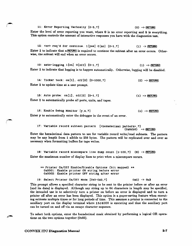
11: Error Reporting Verbosity [0-5.?] (0) -> (RETURN)
Enter the level of error reporting you want, where 0 is no error reporting and 5 is everything. This option controls the amount of interactive responses you have with the diagnostics test.
12: <er> req'd for continue. l[yes] O[no] [0-1.?] (1) -> (RETURN)
Enter 1 to indicate that a(RETURNJ is required to continue the subtest after an error occurs. Otherwise, the subtest will end when an error occurs.
13: auto-logging 1[on] O[off] [0-1.?] (1) ->~
Enter 1 to indicate that logging is to happen automatically. Otherwise, logging will be disabled.
14: Ticker tock: on[l]. off[O] [0-1000.?]
Enter 1 to update time at a user prompt.
15: Auto probe: on[1]. off[O] [0-1.?]
Enter 1 to automatically probe all ports, units, and tapes.
16: Enable Debug Monitor [y.n.?]
(0) ->~
(1) -> lRET\JRNJ
(n) ->~
Enter y to automatically enter the debugger in the event of an error.
17: Variable record subtest pattern [<hexadecimal pattern>.?] (OX6db6) -> (RETURN)
Enter the hexadecimal data pattern to use for variable record write/read subtests. The pattern may be any length from 1 nibble to 256 bytes. The pattern will be replicated over and over as necessary when formatting buffers for tape writes.
18: Variable record miscompare line dump count [1-100.?] (8) ->(RETURN)
Enter the maximum number of display lines to print when a miscompare occurs.
** Printer On/Off Enable/Disable Options (bit mapped) ** Ox0001: Enable printer ON string before error Ox0002: Enable printer OFF string after error
19: Select Printer On/Off Mode [OxO-Ox3.?] OxO) -> Ox3
This prompt allows a specified character string to be sent to the printer before or after an error (and its data) is displayed. Although any string up to 64 characters in length may be specified, the intended use is to selectively turn a printer on before an error is displayed and to turn a printer off after an error has been displayed. This option is a paper-saving feature when executing subtests multiple times or for long periods of time. This assumes a printer is connected to the auxiliary port on the display terminal where 1 tc4000 is executing and that the auxiliary port can be turned on and off via an escape character sequence.
To select both options, enter the hexadecimal mask obtained by performing a logical OR operations on the two options together {Ox03).
CONVEX ITC Diagnostics Manual 2-7
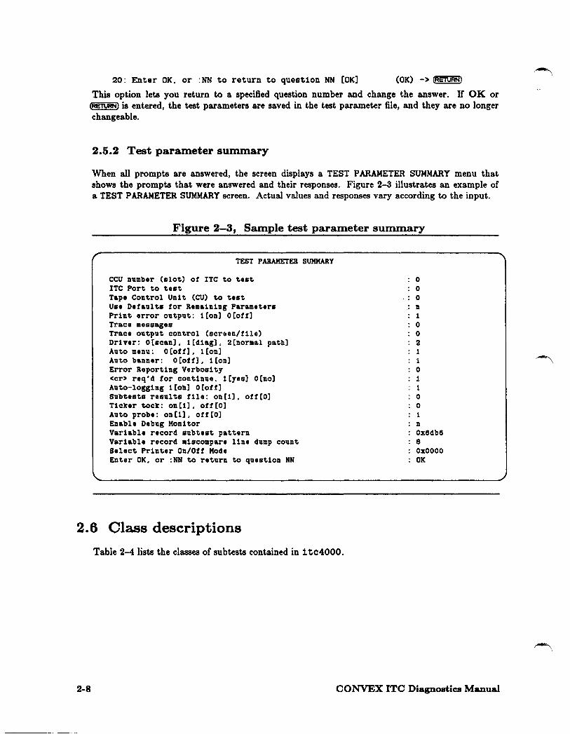
20: Enter OK. or :NN to return to question NN [OK] (OK)->~
This option lets you return to a specified question number and change the answer. If OK or ~ is entered, the test parameters are saved in the test parameter file, and they are no longer changeable.
2.5.2 Test parameter summary
When all prompts are answered, the screen displays a TEST PARAMETER SUMMARY menu that shows the prompts that were answered and their responses. Figure 2-3 illustrates an example of a TEST PARAMETER SUMMARY screen. Actual values and responses vary according to the input.
r
Figure 2-3, Sample test parameter summary
TEST PARAMETER SUMMARY
CCU number (slot) of ITC to test ITC Port to test Tape Control Unit (CU) to test Use Defaults for Remaining Parameters Print error output: 1[on] O[off] Trace messages Trace output control (screen/file) Driver: O[scan], 1[diag], 2[normal path] Auto menu: O[off], l[on] Auto banner: O[off], i[on] Error Reporting Verbosity <er> req'd for continue. 1[yes] O[no] Auto-logging i[on] O[off] Subtests results file: on[i], off[O] Ticker tock: on[i], off[O] Auto probe: on[1], off[O] Enable Debug Monitor Variable record subtest pattern Variable record miscompare line dump count Select Printer On/Off Mode Enter OK. or :NN to return to question NN
0 0
.. 0 n 1 0 0 2 1 1 0 1 1 0 0 i n Ox6db6 8 OxOOOO OK
2. 6 Class descriptions
Table 2-4 lists the classes of subtests contained in 1 tc4000.
2-8 CONVEX ITC Diagnostics Manual
~ '
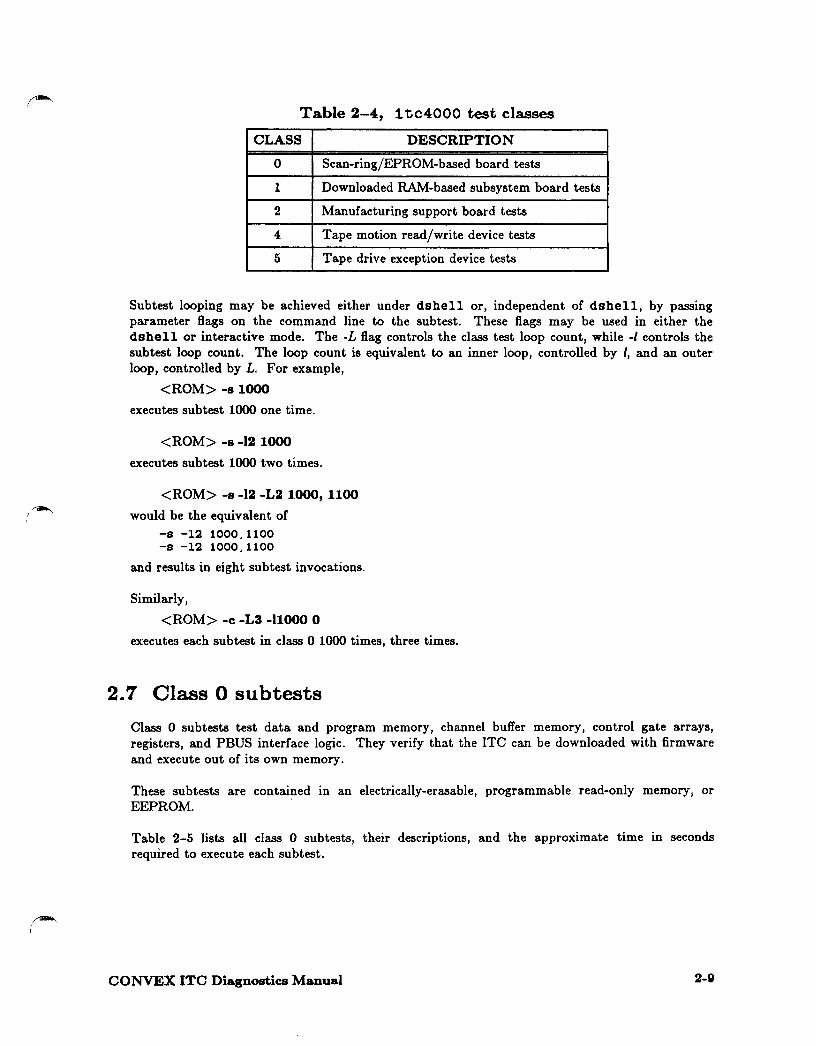
Table 2-4, 1 tc4000 test classes
CLASS DESCRIPTION
0 Scan-ring/EPROM-based board tests
1 Downloaded RAM-based subsystem board tests
2 Manu(acturing support board tests
4 Tape motion read/write device tests
5 Tape drive exception device tests
Subtest looping may be achieved either under dshell or, independent or dshell, by passing parameter flags on the command line to the subtest. These flags may be used in either the dshell or interactive mode. The -L flag controls the class test loop count, while -I controls the subtest loop count. The loop count is equivalent to an inner loop, controlled by I, and an outer loop, controlled by L. For example,
<ROM> -a 1000
executes subtest 1000 one time.
<ROM> -• -12 1000
executes subtest 1000 two times.
<ROM> -a -12 -L2 1000, 1100
would be the equivalent or -s -12 1000.1100 -s -12 1000.1100
and results in eight subtest invocations.
Similarly,
<ROM> -c -L3 -11000 O
executes each subtest in class 0 1000 times, three times.
2.7 Class 0 subtests
Class 0 subtests test data and program memory, channel buffer memory, control gate arrays, registers, and PBUS inter(ace logic. They verify that the ITC can be downloaded with firmware and execute out or its own memory.
These subtests are contained in an electrically-erasable, programmable read-only memory, or EEPROM.
Table 2-5 lists all class 0 subtests, their descriptions, and the approximate time in seconds required to execute each subtest.
CONVEX ITC Diagnostics Manual 2-9

Table 2-5, Class 0 subtests ~'
Subtest Description Time (seconds)
1 Board reset test 1 2 Slot verification test 6 100 Data RAM bit functionality test 10 110 Data RAM column functionality test 4 120 Data RAM uniqueness test 1 130 Data RAM parity test 1 200 Instruction RAM bit functionality test 10 210 Instruction RAM column functionality test 1 220 Instruction RAM uniqueness test 1 230 Instruction RAM parity test 1 240 Instruction RAM execution test 1 300 PMAP RAM bit functionality test 2 310 PMAP RAM column functionality test 6 320 PMAP RAM uniqueness test 1 330 PMAP RAM parity test 1 400 PBUS header generation test 1 410 PBUS access test 3 500 Data buffer port 0 bit functionality test 8 501 Data buffer port 0 column functionality test 3 502 Data buffer port 0 uniqueness test 3 503 Data buffer port 0 parity test 3 510 Data buffer port 1 bit functionality test 10 511 Data buffer port 1 column functionality test 3 512 Data buffer port 1 uniqueness test 3 513 Data buffer port 1 parity test 3 520 Data buffer port 2 bit functionality test 8 521 Data buffer port 2 column functionality test 3 522 Data buff er port 2 uniqueness test 3 523 Data buffer port 2 parity test 3 530 Data buffer port 3 bit functionality test 10 531 Data buffer port 3 column functionality test 3 532 Data buffer port 3 uniqueness test 3 533 Data buffer port 3 parity test 3 604 DPED 0 column functionality test 3 605 DPED 0 parity test 4 614 DPED 1 column functionality test 2 615 DPED 1 parity test 3 616 DPED 2 column functionality test 2 617 DPED 2 parity test 3 618 DPED 3 column functionality test 3 619 DPED 3 parity test 4 620 Data buffer all ports uniqueness test 8
Table 2-5 is continued on the next page.
2-10 CONVEX ITC Diagnostics Manual
~ I
Subtest
630 631 632 633 640 641 642 643 650 651 652 653 660 661 662 663 700 701 702 800 900
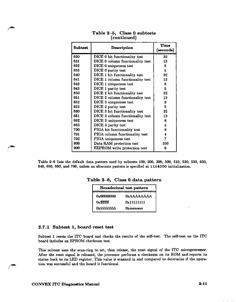
Table 2-5, Class 0 subtests (continued)
Description
DICE 0 bit functionality test DICE 0 column functionality test DICE 0 uniqueness test DICE 0 parity test DICE 1 bit functionality test DICE 1 column functionality test DICE 1 uniqueness test DICE 1 parity test DICE 2 bit functionality test DICE 2 column functionality test DICE 2 uniqueness test DICE 2 parity test DICE 3 bit functionality test DICE 3 column functionality test DICE 3 uniqueness test DICE 3 parity test PIGA bit functionality test PIGA column functionality test PIGA uniqueness test Data RAM protection test EEPROM write protection test
Time (seconds)
32 13 8 5 32 13 8 5 32 13 8 5 32 13 8 5 8 4 7
350 6
Table 2-6 lists the default data pattern used by subtests 100, 200, 300, 500, 510, 520, 530, 630, 640, 650, 660, and 700, unless an alternate pattern is specified at 1 tc4000 initialization.
Table 2-6, Class 0 data pattern
Hexadecimal test pattern
OxOOOOOOOO
Oxffffffff
Ox55555555
2.7.1 Subtest 1, board reset test
OxAAAAAAAA
Oxllllllll
Oxeeeeeeee
Subtest 1 resets the ITC board and checks the results of the self-test. The self-test on the ITC board includes an EPROM checksum test.
This subtest uses the scan-ring to set, then release, the reset signal of the ITC microprocessor. After the reset signal is released, the processor performs a checksum on its ROM and reports its status back to its LED register. This value is scanned in and compared to determine if the operation was successful and the board is functional.
CONVEX ITC Diagnostics Manual 2-11

2. 7 .2 Subtest 2, slot verification test
Subtest 2 uses the scan-ring communication capability to verify that the CCU slot matches the slot of the diagnostic. Specifically, the CCU reads its slot ID from a location on the backplane and uses a multiple of it as a main memory address for common message interface (CMI) data structures. If the slot ID yields the wrong location, it will not be possible to download and communicate with the CCU via CMI.
2.7.3 Subtest 100, data RAM bit functionality test
Subtest 100 tests data RAM bit functionality. It performs a true/complement pattern test for all locations in data RAM using the patterns in Table 2-6. Only longword access is checked.
2.7.4 Subtest 110, data RAM column functionality test
Subtest 110 tests data RAM column functionality. It performs a walking ls and Os test on the first word in each bank of data RAM (moving from least significant bit to most significant bit).
2.7.5 Subtest 120, data RAM uniqueness test
Subtest 120 tests data RAM location uniqueness. It writes an incrementing value to each location in the data RAM, then verifies that all locations contain the expected value. ~,
2. 7 .6 Subtest 130, data RAM parity test
Subtest 130 tests data RAM parity checking. It performs a walking ls and O's test, writing a location in data RAM with inverted parity and then reading it to generate a parity error. The location is rewritten with correct parity when the test is complete. All four parity bits are checked individually.
2.7.7 Subtest 200, instruction RAM bit functionality test
Subtest 200 tests instruction RAM bit functionality. It performs a true/complement pattern test for all locations in instruction RAM using the patterns in Table 2-6. Only longword accesses are checked.
2. 7 .8 Subtest 210, instruction RAM column functionality test
Subtest 210 tests instruction RAM column functionality. It performs a walking ls and Os test on the first word in each bank of instruction RAM (moving from least significant bit to most significant bit).
2-12 CONVEX ITC Diagnostics Manual

h-i' I
2.7.9 Subtest 220, instruction RAM uniqueness test
Subtest 220 tests instruction RAM location uniqueness. It writes an incrementing value to each location in the instruction RAM, then verifies that all locations contain the expected value. Only longword accesses are checked for uniqueness.
2. 7 .10 Subtest 230, instruction RAM parity test
Subtest 230 tests instruction RAM parity checking. It performs a walking ls and Os test, writing a location in instruction RAM with inverted parity and then reading it to generate a parity error. The location is rewritten with correct parity when the test is complete. All four parity bits are checked simultaneously.
2.7 .11 Subtest 240, instruction RAM execution test
Subtest 240 tests that code in the instruction RAM can be correctly executed. Code that computes the EEPROM checksum is copied out of EEPROM into IRAM. The IRAM code is called, computing the checksum and returning to EEPROM. IC an instruction fault occurs, an error is reported back to the SPU.
2.7.12 Subtest 300, PMAP RAM bit functionality test
Subtest 300 tests PMAP RAM bit functionality. It performs a true/complement pattern test for all locations in PMAP RAM using the patterns in Table 2-6. Only longword access is checked.
2. 7 .13 Subtest 310, PMAP RAM column functionality test
Subtest 310 tests PMAP RAM column functionality. It performs a walking ls and Os test on the first word in each bank of PMAP RAM (moving from least significant bit to most significant bit).
2.7.14 Subtest 320, PMAP RAM uniqueness test
Subtest 320 tests PMAP RAM location uniqueness. It writes an incrementing value to each location in PMAP RAM, then verifies that all locations contain the expected value. Only longword accesses are checked for uniqueness.
2. 7 .15 Subtest 330, PMAP RAM parity test
Subtest 330 tests that parity checking is working for the PMAP registers. The first PMAP register is written with a zero and bad parity. The 88100 processor then reads the PMAP register and verifies that the access generated a data fault and that the fault store register (FSR) logs an IBUS fault. The process is repeated with a pattern of Oxfefefefe (odd number of bits in each byte).
CONVEX ITC Diagnostics Manual 2-13

(NOTE)
A window access on a PMAP register with bad parity is not detected by the ITC. The ITC depends on the memory system (PBI) to detect the error. Verification that this condition is properly processed is outside the scope of the level 0 test.
The PMAP registers are word-accessible only.
2.7.16 Subtest 400, PBUS header generation test
Subtest 400 verifies that the PMAP translation and PBI header generation are working properly. The PMAP is first initialized with a translation map, and the PBI is then set to test mode via the diagnostic control register (DCR). The 88100 processor then attempts a write to main memory (the transaction is terminated via test mode). The 88100 processor then reads the upper, then the lower, 32 bits of the PB2LBREG diagnostic register, simulating the header. This value is then verified by the value written to the PMAP and the size of the transfer. Miscompare will result in failure, and both the expected and the actual values are reported back to the SPU.
2. 7 .17 Subtest 410, PBUS access test
Subtest 410 reads, verifies, and echos a pattern placed in main memory by the SPU. This test ~. verifies that the SPU and the ITC agree on the location of main memory and of the proper byte ordering in that memory.
2. 7 .18 Subtests 500, 510, 520, and 530 (data buffer bit functionality tests)
Subtests 500, 510, 520, and 530 test the bit functionality of the data buffer for each port. They perform a true/ complement pattern test for all locations in the data buffer using the patterns in Table 2-6. Only longword access is checked. Table 2-7 lists the subtest number and the port it tests.
Table 2-7, Data buffer bit functionality subtests
Subtest Port tested
500 Port 0
511 Port 1
521 Port 2
531 Port 3
2-14 CONVEX ITC Diagnostics Manual

!"""" \ 2.7.19 Subtests 501, 511, 521, and 531 (data buffer column functionality
tests)
Subtests 501, 511, 521, and 531 test the column functionality of the data buffer for each port. They perform a walking ls and Os test on the first word in each bank of the data buffer (moving from least significant bit to most significant bit). Table 2-8 lists the subtest number and the port it tests.
Table 2-8, Data buffer column functionality subtests
Subtest Port tested
501 Port 0
511 Port 1
521 Port 2
531 Port 3
2.7.20 Subtests 502, 512, 522, and 532 (data buffer uniqueness tests)
Subtests 502, 512, 522, and 532 test the location uniqueness of the data buffer for each port. It writes an incrementing value to each location in the data buffer, then verifies that all locations contain the expected value. Only longword accesses are checked for uniqueness. Table 2-9 lists the subtest number and the port it tests.
Table 2-9, Data buffer uniqueness subtests
Subtest Port tested
502 Port 0
512 Port 1
522 Port 2
532 Port 3
2.7.21 Subtests .503, 513, 523, and 533 (data buffer parity tests)
Subtests 503, 513, 523, and 533 test that the parity checking is working for the data buffer for each port. The first data buffer register is written with a zero and bad parity. The 88100 processor then reads the data buffer register and verifies that the access generated a data fault and that the FSR logs an LBUS fault. The process is repeated with a pattern of Oxfefefefe (odd number of bits in each byte). Table 2-10 lists the subtest number and the port it tests.
CONVEX ITC Diagnostics Manual 2-15

Table 2-10, Data buffer parity subtests
Subtest Port tested
503 Port 0
513 Port 1
523 Port 2
533 Port 3
(NOTE) For subtests 513 and 523, a window access on a PMAP register with bad parity is not detected by the ITC. The ITC depends on the memory system (PBI) to detect the error. Verification that this condition is properly processed is outside the scope of the level 0 test.
The PMAP registers are word-accessible only.
2.7.22 Subtests 604, 614, 616, and 618 (DPED column functionality tests)
Subtests 604, 614, 616, and 618 test the column functionality of the data path and error detection (DPED) basic control register at address fl0090 for each port. They perform a walking ls and Os test on the lower 30 bits of the four-byte word (moving from least significant bit to most significant bit). Table 2-11 lists the subtest number and the port it tests.
Table 2-11, DPED column functionality subtests
Subtest Port tested
604 Port 0
614 Port 1
616 Port 2
618 Port 3
2.7.23 Subtests 605, 615, 617, and 619 (DPED parity tests)
Subtests 605, 615, 617, and 619 test that the parity checking is working for the DPED for each port. The first data buffer register is written with a zero and bad parity. The 88100 processor then reads the data buffer register and verifies that it generated a data fault, and that the FSR logs an LBUS fault. The process is repeated with a pattern of Oxfefefefe (odd number of bits in each byte). Table 2-12 lists the subtest number and the port it tests.
2-18 CONVEX ITC Diagnostics Manual

Table 2-12, DPED parity subtests
Subtest Port tested
605 Port 0
615 Port 1
617 Port 2
619 Port 3
2.7.24 Subtest 620, data buffer all ports uniqueness test
Subtest 620 tests the location uniqueness of the data buffer. It writes an incrementing value to each location in the data buffers (16 kbytes), then verifies that all locations contain the expected value. Only longword accesses are checked for uniqueness.
2.7.25 Subtests 630, 640, 650, and 660 (DICE bit functionality tests)
Subtests 630, 640, 650, and 660 test the bit functionality of the device interface command execution (DICE) registers for each port. They perform a true/complement pattern test for CREG, OPREG, TCREG, HCREG, FCREG, XREG, and HREG in the DICE, using the patterns in Table 2-6. Only longword access is checked, and the most significant bit of OPREG is not checked. Table 2-13 lists the subtest number and the port it tests.
Table 2-13, DICE bit functionality subtests
Subtest Port tested
630 Port 0
640 Port 1
650 Port 2
660 Port 3
2.7.26 Subtests 631, 641, 651, and 661 (DICE column functionality tests)
Subtests 631, 641, 651, and 661 test the column functionality of the DICE registers at address ffOOOO for each port. They perform a walking ls and Os test on the first word of OPREG, TCREG, HCREG, FCREG, XREG, and HREG (moving from least significant bit to most significant bit, or to second most significant bit of OPREG). Table 2-14 lists the subtest number and the port it tests.
CONVEX ITC Diagnostics Manual 2-17

Table 2-14, DICE column functionality subtests
Subtest Port tested
631 Port 0
641 Port 1
651 Port 2
661 Port 3
2.7.27 Subtests 632, 642, 652, and 662 (DICE uniqueness tests)
Subtests 632, 642, 652, and 662 test the location uniqueness or the DICE registers at address flOOOO ror each port. They write an incrementing value to each location in OPREG, TCREG, HCREG, FCREG, XREG, and HREG, then verifies that all locations contain the expected value. Only longword accesses are checked ror uniqueness and the most significant bit or OPREG is not checked. Table 2-15 lists the subtest number and the port it tests.
Table 2-15, DICE uniqueness subtests
Subtest Port tested
632 Port 0
642 Port 1
652 Port 2
662 Port 3
2.7.28 Subtests 633, 643, 653, and 663 (DICE parity tests)
Subtests 633, 643, 653, and 663 test that the parity checking is working ror the DICE registers for each port. The first DICE register is written with a zero and bad parity. The 88100 processor then reads the DICE register and verifies that the access generated a data Cault and that the FSR logs an IBUS Cault. The process is repeated with a pattern or Oxfererere (odd number or bits in each byte). Table 2-16 lists the subtest number and the port it tests.
2-18 CONVEX ITC Diagnostics Manual

~ I
~ i.
Table 2-16, DICE parity subtests
Subtest Port tested
633 Port 0
643 Port 1
653 Port 2
663 Port 3
2.7.29 Subtest 700, PIGA bit functionality test
Subtest 700 tests PIGA bit functionality. It performs a true/complement pattern test for all loca-tions in the PIGA, using the patterns in Table 2-6. Only longword access is checked.
2. 7 .30 Subtest 701, PIGA column functionality test
Subtest 701 tests PIGA column functionality. It performs a walking ls and Os test on the first word in each bank of PIGA (moving from least significant bit to most significant bit).
2.7.31 Subtest 702, PIGA uniqueness test
Subtest 702 tests PIGA location uniqueness. It writes a incrementing value to each location in the PIGA, then verifies that all locations contain the expected value. Only longword access is checked.
2.7.32 Subtest 800, data RAM protection test
Subtest 800 tests Data RAM read/write protection. It writes values to every page in the data RAM, then verifies that all locations contain the expected value. This procedure is then repeated twice, first with the data RAM read protection enabled, then with the data RAM write protection enabled. In both of these cases, proper error detection is verified.
2.7.33 Subtest 900, EEPROM write protection test
Subtest 900 verifies that the local processor on the CCU cannot write its EEPROM unless it is write enabled.
208 Class 1 subtests
Class 1 subtests test all internal CCU diagnostic hardware logic and perform additional CCUspecific board tests.
CONVEX ITC Diagnostics Manual 2-19

(CAUTION)
Run these tests with no devices connected to the IPI interface. Otherwise, unexpected results may occur. .
Table 2-17 lists all class 1 subtests, their descriptions, and the approximate time in seconds required to execute each subtest.
Table 2-17, Class 1 subtests
Subtest Description Time
(seconds}
1000 Port 0 channel-to-memory data path test 041
1010 Port 1 channel-to-memory data path test 04 1020 Port 2 channel-to-memory data path test 04 1030 Port 3 channel-to-memory data path test 04 1100 Port 0 memory-to-channel data path test 04 1110 Port 1 memory-to-channel data path test 04 1120 Port 2 memory-to-channel data path test 04 1130 Port 3 memory-to-channel data path test 04 1200 Port 0 channel-to-memory boundary test 90 1210 Port 1 channel-to-memory boundary test 90 1220 Port 2 channel-to-memory boundary test 90 1230 Port 3 channel-to-memory boundary test 90 1300 Port 0 memory-to-channel boundary test 90 1310 Port 1 memory-to-channel boundary test 90 1320 Port 2 memory-to-channel boundary test 90 1330 Port 3 memory-to-channel boundary test 90 1400 Port 0 alignment test 04 1410 Port 1 alignment test 04 1420 Port 2 alignment test 04 1430 Port 3 alignment test 04 1500 Port 0 arbiter test 04 1510 Port 1 arbiter test 04 1520 Port 2 arbiter test 04 1530 Port 3 arbiter test 04
1 Thia subtest. may take 25-30 seconds because or the time needed to download the driver.
2.8.1 Subtests 1000, 1010, 1020, and 1030 (channel-to-memory data path tests)
Subtests 1000, 1010, 1020, and 1030 simulate a READ tape drive operation. A 4,096-byte record is sent from a channel to memory, and data in both the data buffer and memory is checked and verified. Any discrepancy is reported !or each channel.
Subtest 1000 is performed twice, to check the operation of both register sets for each port in the PIGA.
2-20 CONVEX ITC Diagnostics Manual
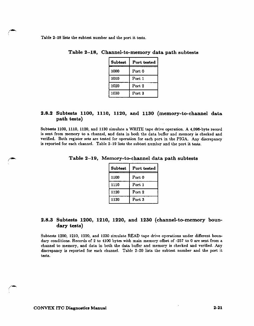
Table 2-18 lists the subtest number and the port it tests.
Table 2-18, Channel-to-memory data path subtests
Subtest Port tested
1000 Port 0
1010 Port 1
1020 Port 2
1030 Port 3
2.8.2 Subtests 1100, 1110, 1120, and 1130 (memory-to-channel data path tests)
Subtests 1100, 1110, 1120, and 1130 simulate a WRITE tape drive operation. A 4,096-byte record is sent from memory to a channel, and data in both the data buffer and memory is checked and verified. Both register sets are tested for operation for each port in the PIGA. Any discrepancy is reported for each channel. Table 2-19 lists the subtest number and the port it tests.
Table 2-19, Memory-to-channel data path subtests
Subtest Port tested
1100 Port 0
1110 Port 1
1120 Port 2
1130 Port 3
2.8.3 Subtests 1200, 1210, 1220, and 1230 (channel-to-memory boundary tests)
Subtests 1200, 1210, 1220, and 1230 simulate READ tape drive operations under different boundary conditions. Records of 2 to 4100 bytes with main memory offset of -257 to 0 are sent from a channel to memory, and data in both the data buffer and memory is checked and verified. Any discrepancy is reported for each channel. Table 2-20 lists the subtest number and the port it tests.
CONVEX ITC Diagnostics Manual 2-21

Table 2-20, Channel-to-memory boundary subtests
Subtest Port tested
1200 Port 0
1210 Port 1
1220 Port 2
1230 Port 3
2.8.4 Subtests 1300, 1310, 1320, and 1330 (memory-to-channel boundary tests)
Subtests 1300, 1310, 1320, and 1330 simulate WRITE tape drive operations under different boundary conditions. Record size or 2 to 4100 bytes with main memory offset of -257 to 0 is sent from memory to a channel, and data in both the data buffer and memory is checked and verified. Any discrepancy is reported !or each channel. Table 2-21 lists the subtest number and the port it tests.
Table 2-21, Memory-to-channel boundary subtests
Subtest Port tested
1300 Port 0
1310 Port 1
1320 Port 2
1330 Port 3
2.8.5 Subtests 1400, 1410, 1420, and 1430 (alignment tests)
Subtests 1400, 1410, 1420, and 1430 write data to main memory that is not mapped and expect a PBUS error. Both register sets are tested for operation for each port in the PIGA. Table 2-22 lists the subtest number and the port it tests.
Table 2-22, Alignment subtests
Subtest Port tested
1400 Port 0
1410 Port 1
1420 Port 2
1430 Port 3
2-22 CONVEX ITC Diagnostics Manual

~ I
2.8.6 Subtests 1500, 1510, 1520, and 1530 (arbiter tests)
Subtests 1500, 1510, 1520, and 1530 simulate a READ tape drive operation. A 4,096-byte record is sent Crom a channel to memory with buffer count register initially set to -1. Starting memory locations are checked to be sure that it is not written by the arbiter logic. Buffer counter register is then incremented to 1. Data buffer and memory is checked and verified. Any discrepancy is reported. Table 2-23 lists the subtest number and the port it tests.
Table 2-23, Arbiter subtests
Subtest Port tested
1500 Port 0
1510 Port 1
1520 Port 2
1530 Port 3
2.9 Class 2 subtests, manufacturing support board tests
The class 2 sub tests verify that the ITC main data paths operate properly, using an external loopback cable or connector. Subtest 2000 requires the connection of a special external loopback cable; subtest 2010 requires the connection of a special external loopback connector.
The special external loopback cable is a regular IPI jumper cable (CONVEX Part Number 604-500007-001) to which you must make the following modifications:
BUSA bit 0-7 oC end 1 BUSA parity of end 1 BUSB bit 0-7 oC end 1 BUSB parity or end 1 DC Ground of end 1
connected to BUSB bit 0-7 of end 2 connected to BUSB parity of end 2 connected to BUSA bit 0-7 or end 2 connected to BUSA parity of end 2 connected to DC Ground of end 2
Other signal pins are disconnected.
The special external loopback connector is a regular IPI male connector to which you must make the following modifications:
SELO connected to ATNI MASO connected to SL VI SYNO connected to SYNI
For each subtest, the diagnostic prompts the user to attach the loopback connecter or cable.
Table 2-24 lists all class 2 subtests, their descriptions, and the approximate time in seconds required to execute each subtest.
CONVEX ITC Diagnostics Manual 2-23

Table 2-24, Class 2 subtests
Subtest Description Time (seconds)
2000 Transceiver bus A/bus B bit functionality test 4 2010 Transceiver control signals bit functionality test 4
2.9.1 Subtest 2000, transceiver bus A/bus B bit functionality test
Subtest 2000 writes a pattern of ls and Os to the bus A signal on one channel and verifies the pattern by reading the bus B signal on another channel.
2.9.2 Subtest 2010, transceiver control signals bit functionality test
Subtest 2010 writes a pattern of ls and Os to the control signal and verifies that the channel is in the correct state.
2.10 Class 4 subtests, tape motion read/write device tests
Class 4 subtests verify tape motion and the ability to read and write data to the tape. Class 4 subtests use the standard common message interface ( CMI) command set.
The first three subtests do not perform any data verification checks. A status check is made prior to all commands to ensure that the tape is online and ready. Before any command using forward motion is issued, a check is made to ensure that the physical end of the tape has not been reached. For all write commands, a check is made to ensure that the write protect has not been set on the tape media. A Beginning-of-Tape (BOT) status bit set check is done for every REWIND command to check completion status. The REWIND command will not be sent to the tape driver if the tape media is already at BOT.
Each subtest has no dependency on prior execution of other subtests. The execution of the subtests in sequential order will check the tape subsystem in order of increasing complexity.
2-24 CONVEX ITC Diagnostics Manual

~ I I
,Jlll"""
Table 2-25 lists all class 4 subtests, their descriptions, and the approximate time in seconds required to execute each subtest.
Table 2-25, Class 4 subtests
Subtest Description Time (seconds)
4000 Tape mark test 124 4010 Space record test 67 4030 Long block read test 99 4040 Fixed record size read/write test 328 4050 Write file UNIX-style test 178
2.10.1 Subtest 4000, tape mark test
Subtest 4000 verifies that a tape mark can be written to the tape and detected. The subtest first verifies that a written tape mark can be detected in the forward direction. Next, 5 tape records, each followed by a tape mark, are written. SPACE FILE commands are then issued in both the forward and reverse directions. Tape position is then verified by testing for the presence or absence or a tape mark. The following is an example or a failed tape mark test:
Error: Expected tape mark status did not occur while fwd space file
2.10.2 Subtest 4010, space record test
Subtest 4010 verifies the FORWARD SPACE RECORD and the BACK SPACE RECORD commands. The subtest begins by rewinding the tape and writing two records followed by a tape mark. The subtest then writes 2 records or decreasing size to the tape, the biggest or these records being 1,000 bytes and the smallest being 50 bytes. A tape mark is then written to the tape. A space record test is then performed between the end points denoted by the tape marks. The subtest then issues a varying series of FORWARD SPACE RECORD commands. The subtest verifies the success or the space record test by checking for the presence of a filemark. The testing sequence is repeated using the BACK SPACE RECORD command. The subtest then repeats the testing sequence with a combination or FORWARD SP ACE and BACK SP ACE commands. The Collowing is an example of a failed space record test:
Error: Unexpected tape mark status sensed while fwd space rec
2.10.3 Subtest 4030, long block read test
Subtest 4030 verifies that the long-block status bit indicates correctly whether a long block is present. This test begins by writing a series or records correctly on the tape, starting with a record or 80 bytes and each subsequent record being four times the size or the previous record.
CONVEX ITC Diagnostics Manual 2-26
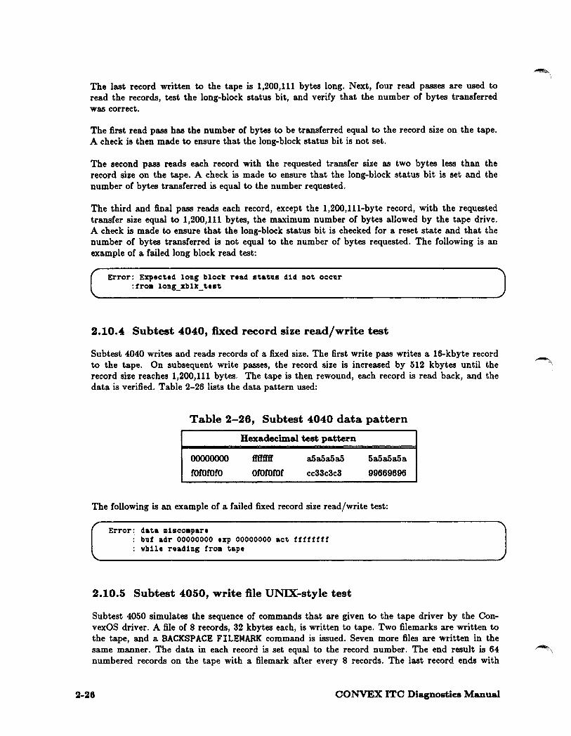
The last record written to the tape is 1,200,111 bytes long. Next, four read passes are used to read the records, test the long-block status bit, and verify that the number of bytes transferred was correct.
The first read pass has the number of bytes to be transferred equal to the record size on the tape. A check is then made to ensure that the long-block status bit is not set.
The second pass reads each record with the requested transfer size as two bytes less than the record size on the tape. A check is made to ensure that the long-block status bit is set and the number of bytes transferred is equal to the number requested.
The third and final pass reads each record, except the 1,200,111-byte record, with the requested transfer size equal to 1,200,111 bytes, the maximum number of bytes allowed by the tape drive. A check is made to ensure that the long-block status bit is checked for a reset state and that the number of bytes transferred is not equal to the number of bytes requested. The following is an example of a failed long block read test:
Error: Expected long block read status did not occur :from long_xblk_test
2.10.4 Subtest 4040, fixed record size read/write test
Subtest 4040 writes and reads records of a fixed size. The first write pass writes a 16-kbyte record to the tape. On subsequent write passes, the record size is increased by 512 kbytes until the ~. record size reaches 1,200,111 bytes. The tape is then rewound, each record is read back, and the data is verified. Table 2-26 lists the data pattern used:
Table 2-26, Subtest 4040 data pattern
00000000
rorororo
Hexadecimal test pattern
ffffft'ff
orororof a5a5a5a5
cc33c3c3
5a5a5a5a
99669696
The following is an example of a failed fixed record size read/write test:
, Error: data miscompare
buf adr 00000000 exp 00000000 act ffffffff vhile reading from tape
2.10.5 Subtest 4050, write file UNIX-style test
Subtest 4050 simulates the sequence of commands that are given to the tape driver by the ConvexOS driver. A file of 8 records, 32 kbytes each, is written to tape. Two filemarks are written to the tape, and a BACKSPACE FILEMARK command is issued. Seven more files are written in the same manner. The data in each record is set equal to the record number. The end result is 64 numbered records on the tape with a filemark after every 8 records. The last record ends with
2-26 CONVEX ITC Diagnostics Manual

two filemarks. The tape is rewound. All records are read and verified, and all filemarks are verified to be in the right locations on the tape. The following is an example of a failed write file UNIX-style test:
Error: Expected tape mark status did not occur vhile verif y1ng last tapemark on tape
2.11 Class 5 subtests, tape drive exception tests
Class 5 subtests test various conditions that do not usually occur during normal tape drive operations. These exception subtests test the tape driver and controller stability and integrity when such operations such as ZERO BYTES READ or WRITE commands are submitted to the tape driver.
Table 2-27 lists all class 5 subtests, their descriptions, and the approximate time m seconds required to execute each subtest.
Table 2-27, Class 5 subtests
Subtest Description Tim.e
(seconds)
5000 Beginning-of-tape (BOT) exception test 029 5010 Zero-length operations exception test 057 5020 End-of-data (EOD) status exception test 089
2.11.1 Subtest 5000, beginning-of-tape (BOT) status exception test
This subtest rewinds the tape then writes a tape filemark. Three consecutive BACKSPACE FILE commands are issued. After the first BACKSPACE FILE, the BOT status bit should be set, as well as the tape mark status bit. At the completion of the second and third BACKSPACE FILE, the BOT status bit should be set. A FORWARD SP ACE command is then issued. The BOT status bit should be reset and the tape mark status bit should be set.
The tape is rewound and a 256-byte record is written. Three BACKSPACE RECORD commands are issued consecutively. After the first BACKSPACE RECORD commands are complete, the BOT status bit should be set. A FORWARD SPACE RECORD command is then issued. The BOT status bit should be reset.
2.11.2 Subtest 5010, zero-length operations exception test
Subtest 5010 rewinds the tape and writes two 4-kbyte records with known patterns. The zerolength operations are commands formatted to write 0 bytes, read 0 bytes, forward space 0 records, forward space 0 files, backspace 0 records, and backspace 0 files. Each of these zerolength operations is preceded by a backspace record of count = 1. The second record is then read and verified. No tape motion is expected for any of the zero-length commands sent to the tape driver.
CONVEX ITC Diagnostics Manual 2-27
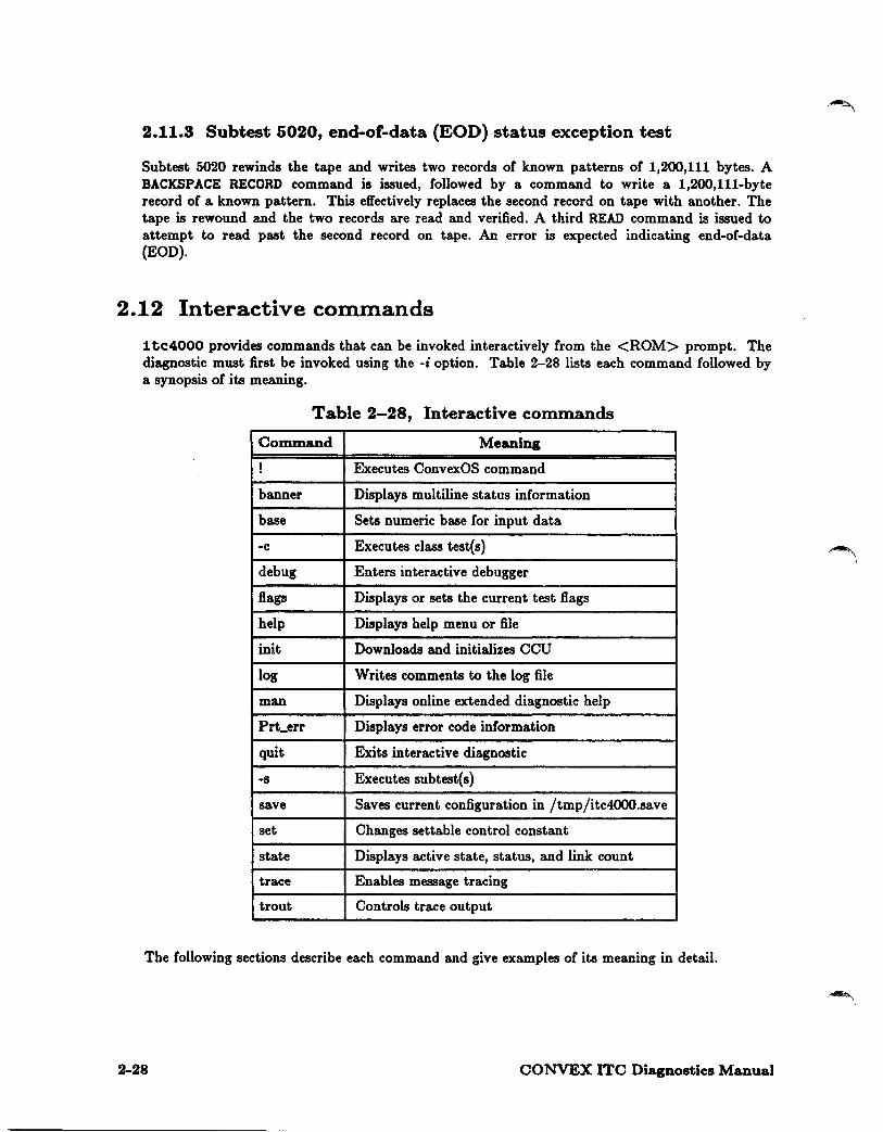
2.11.3 Subtest 5020, end-of-data (EOD) status exception test
Subtest 5020 rewinds the tape and writes two records of known patterns of 1,200,111 bytes. A BACKSPACE RECORD command is issued, followed by a command to write a 1,200,111-byte record of a known pattern. This effectively replaces the second record on tape with another. The tape is rewound and the two records are read and verified. A third READ command is issued to attempt to read past the second record on tape. An error is expected indicating end-of-data (EOD).
2.12 Interactive commands
1 tc4000 provides commands that can be invoked interactively from the <ROM> prompt. The diagnostic must first be invoked using the -i option. Table 2-28 lists each command followed by a synopsis of its meaning.
Table 2-28, Interactive commands
Command Meaning
! Executes ConvexOS command
banner Displays multiline status information
base Sets numeric base for input data
-c Executes class test(s)
debug Enters interactive debugger
flags Displays or sets the current test flags
help Displays help menu or file
init Downloads and initializes CCU
log Writes comments to the log file
man Displays online extended diagnostic help
Prt_err Displays error code information
quit Exits interactive diagnostic
-s Executes subtest(s)
save Saves current configuration in /tmp/itc4000.save
set Changes settable control constant
state Displays active state, status, and link count
trace Enables message tracing
trout Controls trace output
The following sections describe each command and give examples of its meaning in detail.
2-28 CONVEX ITC Diagnostics Manual
~I

~ I
2.12.1
Provides a shell hook to execute ConvexOS operating system commands without exiting the diagnostic.
The format for this command is
! command
where command is the ConvexOS command to execute.
The foil owing example illustrates the use of this command.
! Vi file Edits the file file with the vi editor. Upon exiting the editor, control is returned to the diagnostic.
2.12.2 banner
Clears the screen and displays a multiline information banner across the top of the screen.
The format for this command is
banner
The banner is in the form of:
name version date ccu[no.] [status] port[no.] [status] drive[no.] [status] [status] clk[status]
state: CURSTATE trace: STATE to: WHERE verb: LEVEL print: STATE
where
name
version
date
CCU no
ccu atatua
port no
port atatua
drive no
drive atatua
elk rate
is the name of the diagnostic.
is the build/release version.
is the current date.
is the selected CCU under test.
indicates whether the CCU has been loaded; options are loaded or blank.
is the selected CCU port or channel under test.
indicates whether the port has been probed; options are probed or blank.
is the selected tape drive control unit under test.
indicates whether the drive is attached/connected; options are attached, connected or blank.
is the clock rate of the ITC, where rate can be normal or margin.
CONVEX ITC Diagnostics Manual 2-29

2-30
state curatate is the initialization level of CCU/diagnostic, where curatate is one of the following:
trace atate
to where
verb level
ROM
RAM
currently communicating via scan-ring.
currently communicating via MBS/CMI, but cannot communicate with the selected control unit. Have downloaded the driver and probed the ports, but could not attach to the control unit.
NORMAL PATH
DEBUG
currently communicating with the CCU via MBS/CMI, have probed the ports, attached to the selected control unit, and connected to the desired tape drive
currently using the interactive debugger, or have downloaded the diagnostic driver and have probed, attached, and connected.
indicates whether tracing is enabled; options are on or off. When tracing is enabled, all CMl/MBS messages between the SPU and the CCU will be collected, interpreted, and directed to the location specified by to.
indicates the destination of the output from the trace command, where where is one of the following:
FILE all trace output will be stored in the file /tmp/itc4000.log. /tmp/itc4000.log is closed and reopened upon every invocation of a subtest in order to limit its size.
SCREEN all trace output will be directed to the screen.
is the current verbosity level as set in the initial parameter selection or the set -s verb command. level ranges from 0-5, where the higher the level, the more verbose the error and logic flow reporting is. Verbosity level 5 is reserved for software debug, and subtests will not be executed.
when enabled via the initial parameter selection or the set -s printer 1 command, all error messages will be printed.
CONVEX ITC Diagnostics Manual

~ \
2.12.3 base
Sets the numeric base for all input used as test parameters.
The format for this command is
base [ option]
where option is one of the following:
b Binary
d Ten or decimal
o Octal
x Hexadecimal
2.12.4 -c
Executes an entire class of tests, with looping provided.
The format for this command is
-e [-option ] [ clno J
where option is one of the following:
L Controls the number of times that each test in the class is executed
Controls the number of times that each subtest is executed before proceeding on to the next subtest
and clno is the class number(s) to execute. clno can be specified in any of the following formats:
N A specific class number
N,N, ... N A list of specific class numbers
N-N A range of class numbers, with the specific beginning and ending classes numbers included
The following examples illustrate the use of this command.
-c
-c 0-4
No test would be executed. A list of all class tests and their descriptions would be presented.
Executes all subtests in classes 0,1,2,3, and 4.
-c -L10 -110 0, 1, 2 Executes each subtest in class 0 ten consecutive times, then repeats the process ten times, then repeats the whole sequence again for all subtests in class 1 and 2. If each class had 10 tests, then the above command would result in 3,000 tests being performed. Each subtest would have been executed 100 times.
CONVEX ITC Diagnostics Manual 2-31

2.12.5 debug
Enters the interactive debugger.
(NOTE)
The debugger can only be entered from the normal path mode. This command does not work Crom the <ROM> prompt; in that case, you must issue an 1n1 t command before debug will work.
The Cormat (or this command is
init debug [-option] [command]
where
option
command
is one or the following:
f Forces a reinitialization (download driver, probe, attach, connect)
h Displays help information for this command _
n Suppresses initialization, even if it is required
Is a specific debugger command. The debugger will execute that command and return back to the main command processor. A script file may be executed Crom the main level via the debugger. Once in the debugger, online help is available.
The following examples illustrate the use of this command.
debug
debug -n
debug -n <testall
2.12.6 flags
Displays the dshell test flags.
2-32
Initializes the selected CCU, port, unit, and tape by downloading the current driver and doing an init, probe, attach, and connect. It then prompts for further input with the <debug> prompt.
Enters the debugger without downloading the driver and initializing the subsystem. Useful when the intent of entering the debugger is to utilize its powerful script processor to do scan-level subtests.
Enters the debugger without initialization, and submits the script file teatall. Once the teatall script expires, control is returned to the main command processor.
CONVEX ITC Diagnostics Manual

(,,,..._
~ I
2.12.7 help
Displays a menu of the most frequently used commands. Commands are classified as internal, common, and frequent. Internal commands are not normally executed Crom the command level. Common commands are the list of all commands. Frequent commands are the most used common commands.
The format for this command is
help [-option] [ command]
where option is one or the following:
a Displays all commands
Displays all internal commands
n Displays all common but normally not displayed commands
and command indicates the specific command Cor which help is needed.
Ir option is omitted, only the most used commands are displayed.
The following examples illustrate the use of this command:
help
help -a
2.12.8 1n1t
Displays the most Crequently used commands
Displays the list of all commands
Initializes the system to the current state of the settable control constants. It then takes any necessary action to ensure that the current settings of all control constants are true.
The Cormat for this command is
init [ -option]
where option is one or the following:
d sets the debug flag to one.
D resets the debug flag to zero.
f Corces a reinitialization even if logic indicates a satisfactory level or initialization. It is good practice to perform a init ·/ after a complicated normal path error, or when doubts exist as to the state of the system.
h displays help information Cor this command.
n suppresses initialization.
2.12.9 log
Closes the log file. This command can also be used to reset the log file (close the file, then reopen it).
CONVEX ITC Diagnostics Manual 2-33

The format (or this command is
log [-option]
where option is one or the Collowing:
c Closes the log file and turns logging off
r Resets the log file; closes the file, then reopens it
2.12.10 man
Provides online information about diagnostic commands.
The format for this command is
man token
where token is the command whose details are to be displayed.
2.12.11 Prt err
Executes the error path for the given error code. Will display the error details to the screen.
The format for this command is
Prt_err err_code
where err_code is the error code whose details are to be displayed.
2.12.12 quit
Exits the interactive diagnostic.
The format (or this command is
q or quit
The last thing done before returning to the calling process (dshell, and so on) is to create a file called /tmp/itc4000.save.
2-34 CONVEX ITC Diagnostics Manual
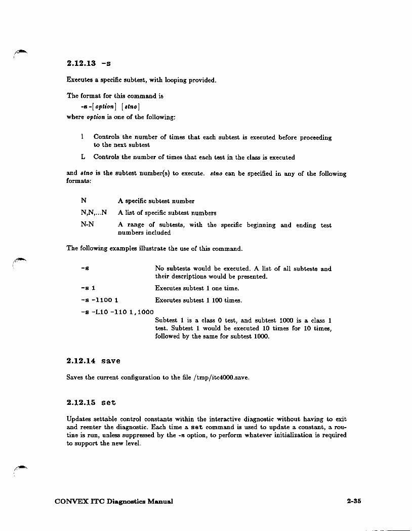
2.12.13 -s
Executes a specific subtest, with looping provided.
The format for this command is
-s -[option] [ atno J
where option is one or the following:
Controls the number of times that each subtest is executed before proceeding to the next subtest
L Controls the number of times that each test in the class is executed
and Btno is the subtest number(s) to execute. Btno can be specified in any of the following formats:
N A specific subtest number
N,N, ... N A list of specific subtest numbers
N-N A range of subtests, with the specific beginning and ending test numbers included
The following examples illustrate the use of this command.
-s
-s 1
-s -1100 1
-s -L10 -110 1, 1000
2.12.14 save
No subtests would be executed. A list of all subtests and their descriptions would be presented.
Executes subtest 1 one time.
Executes subtest 1 100 times.
Subtest 1 is a class 0 test, and subtest 1000 is a class 1 test. Subtest 1 would be executed 10 times for 10 times, followed by the same for subtest 1000.
Saves the current configuration to the file /tmp/itc4000.save.
2.12.15 set
Updates settable control constants within the interactive diagnostic without having to exit and reenter the diagnostic. Each time a set command is used to update a constant, a routine is run, unless suppressed by the -n option, to perform whatever initialization is required to support the new level.
CONVEX ITC Diagnostics Manual 2-35
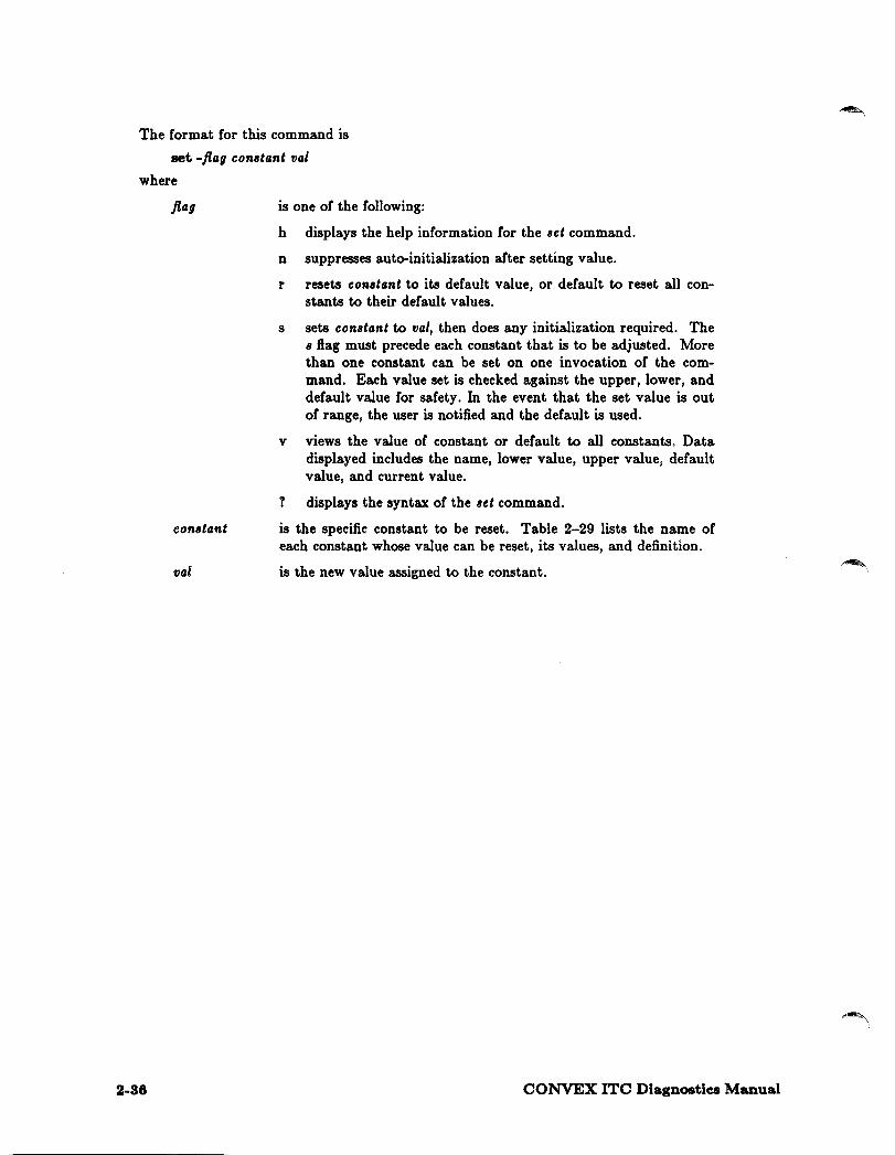
The format for this command is
set -flag constant val
where
flag
constant
val
2-38
is one of the following:
h displays the help information for the set command.
n suppresses auto-initialization after setting value.
r resets constant to its default value, or default to reset all constants to their default values.
s sets constant to val, then does any initialization required. The s flag must precede each constant that is to be adjusted. More than one constant can be set on one invocation of the command. Each value set is checked against the upper, lower, and default value for safety. In the event that the set value is out of range, the user is notified and the default is used.
v views the value of constant or default to all constants. Data displayed includes the name, lower value, upper value, default value, and current value.
? displays the syntax of the set command.
is the specific constant to be reset. Table 2-29 lists the name of each constant whose value can be reset, its values, and definition.
is the new value assigned to the constant.
CONVEX ITC Diagnostics Manual
~ I

Name
banner
CCU
continue
dmode
driver
log
menu
port
probe
state
tape
tock
trace
trout
unit
verb
Table 2-29, Settable constant values
Lval Uval Default Meaning
0 1 1 Auto banner update after~
0 15 0 Selected CCU
0 1 1 Auto continue after error: l[yes] O[no]
0 1 0 Jump to debugger on error: l[on] O[off]
0 2 2 Selected driver: O[scan] l[diag] 2[normal]
0 1 1 Turn logging 1 [on] O[off]
0 1 1 Auto menu display after(RETURNJ
0 1 0 Selected port or channel
0 1 0 Print error output: l[on] O[off]
0 1 1 Auto connect all tape drives: l[yes] O[no]
0 5 0 Current initialization level
0 3 0 Selected tape drive
0 1000 0 Post-cursor time update
0 1 0 Message tracing: l[on] O[off]
0 1 0 Trace output: l[file] O[screen]
0 15 0 Selected control unit (formatter)
0 5 0 Error reporting verbosity /sw debug
(NOTE)
Some of the most frequently used settable control constants can be set directly from the main menu. See trace, trout, or reaulta for more information.
The following example illustrates the use of this command.
set -n -s port 1 -s menu O 1n1t -f
This command suppresses auto initialization, then adjusts the current active port or channel to "l", then turns off the auto menu after every command completion. The following init -/ is recommended to force initialization in order to ensure that future commands can be executed without error (the purpose of auto-init). This command is a means of delayed initialization.
CONVEX ITC Diagnostics Manual 2-37

2.12.16 state
Displays the active state of the selected devices. Displays a table or all of the CCUs, ports, units, and tape drives, and the link counts of each. The link count is incremented upon each selection or that element via init or set -s. This table is used to verify that the driver can dynamically probe, attach, and connect to any physically-attached device.
The Cormat Cor this command is
state
2.12.17 trace
Enables message tracing to the file /tmp/itc4000.log or to the screen. A message trace consists of a CMl/MBS message with certain interpreted fields, the time or receipt or transmission, and the trace count. Tracing is useful in determining the point or Cault in a transaction, especially during field integration.
The Cormat for this command is
trace [ option] [value J [state J
where
option indicates whether to send the message trace to a file (/) or to the screen ( s).
value indicates whether message tracing is enabled (1) or disabled (0).
state indicates whether message tracing is enabled (on) or disabled (off).
The following example illustrates the use or this command.
-s 1 trace -f on 1n1t -f trace off
This command sequence first resets the board by performing subtest 1. It opens a file called /tmp/itc4000.log. The init ·/forces an initialization of the CCU, saving all message traffic associated with the probe, attach, and connect operations. Then the file is closed, making it safe for viewing. If the banner upon return Crom the init -/did not indicate the following:
ccu[Oj[LOADED) port[l][PROBED] drive[15J[ATTAOHEDJ[OONNEOTED)
then the contents of the trace file could be examined to determine exactly what operation failed.
2-38 CONVEX ITC Diagnostics Manual

2.12.18 trout
Controls the destination of the output of the trace command.
The format for this command is
trout [ -h] [ option]
where -h displays help information for this command, and option sets the trace output destination. option can be one of the following:
on, 1 sends output to the file /tmp/itc4000.log.
off, 0 sends output to the screen.
2.13 Interactive debugger
The 1 tc4000 diagnostic provides an interactive debugger that allows the operator to perform some low-level interactions that are helpful when diagnosing a subtest failure. Invoke the debugger with one of the following methods:
• Use the -d option when invoking the diagnostic (itc4000[ x] -d). No subtests are executed.
• The prompt "User Debug Option Mask [OxO-Oxfff, ?] " provides a bit option to force the diagnostic to enter the debugger after an error is reported. To ensure that this option is set, perform a logical OR operation using OxlO in the hexadecimal bit-pattern response for the prompt.
• Enter a ":" when in single-step mode.
Once the interactive debugger is entered, online help commands are available. Figure 2-4 illustrates the information displayed when you enter help.
CONVEX ITC Diagnostics Manual 2-39

r
2-40
Figure 2-4, Interactive debugger online help
Input base specification: OdNN - decimal, OxNN or NN - hexadecimal, the default is hexadecimal
Meta-command sequences: l[UNIX CMD] 11 [UNIX_CHD] <FILE «FILE
- execute UNIX CMD fork a shell and execute UNIX CMD (allows redirection) redirect input from FILE (recursive) end input from current file and change input to FILE
Commands: Commands may be abbreviated as long as the abbreviation is unique.
?
help [COMMAND ... ] cd [DIRECTORY] quit echo C-nl [arg ... ] pause C-nl [seconds] mb begin [end] mw begin [end] ml begin [end] mmb begin [end] mmw begin [end] mml begin [end] fb begin [end] value [iucr hr begin [end] value [iucr fl begin [end] value [iucr ffb begin [end] value [iucr ffw begin [end] value [iucr ffl begin [end] value [iucr
we of count fsr count bsr count fsf count bsf count vphys byte_count [pattern] rphys byte_count
rewind iu connect status unload uuitclr identify
[pattern to
- display currently available debugger commands
- display general or specific help - change to DIRECTORY - exit debug mode - echo statements to display - pause for <C/R> or seconds - modify/[dump] bytes on CCU - modify/[dump] words on CCU - modify/ [dump] longs on CCU - modify/[dump] bytes in MM - modify/[dump] words in MM - modify/[dump] longs in MM
[step]] - fill bytes OU CCU [step]] - fill words OU CCU [step]] - fill longs OU CCU [step]] - fill bytes in Hain Memory [step]] - fill words in Main Memory [step]] - fill longs in Hain Memory
- write end of file count times - forward space record count times - backward space record count times - forward space file count times - backward space file count times - write bytes with optional pat
verify] - read bytes with opt pat to verify - rewind tape unit - attach unit (IO_INIT config unit) - connect unit (IO CONNECT) - read tape statusCIO RDSTATS PHYS) - unload tape (IO_UNLOAD) -- clear tape error status - diagcmd adaptor identify(rev uum)
block -[l(loop)s(block size)f (patteru file)o(output)] - block rd/wr/verify
CONVEX ITC Diagnostics Manual
~I
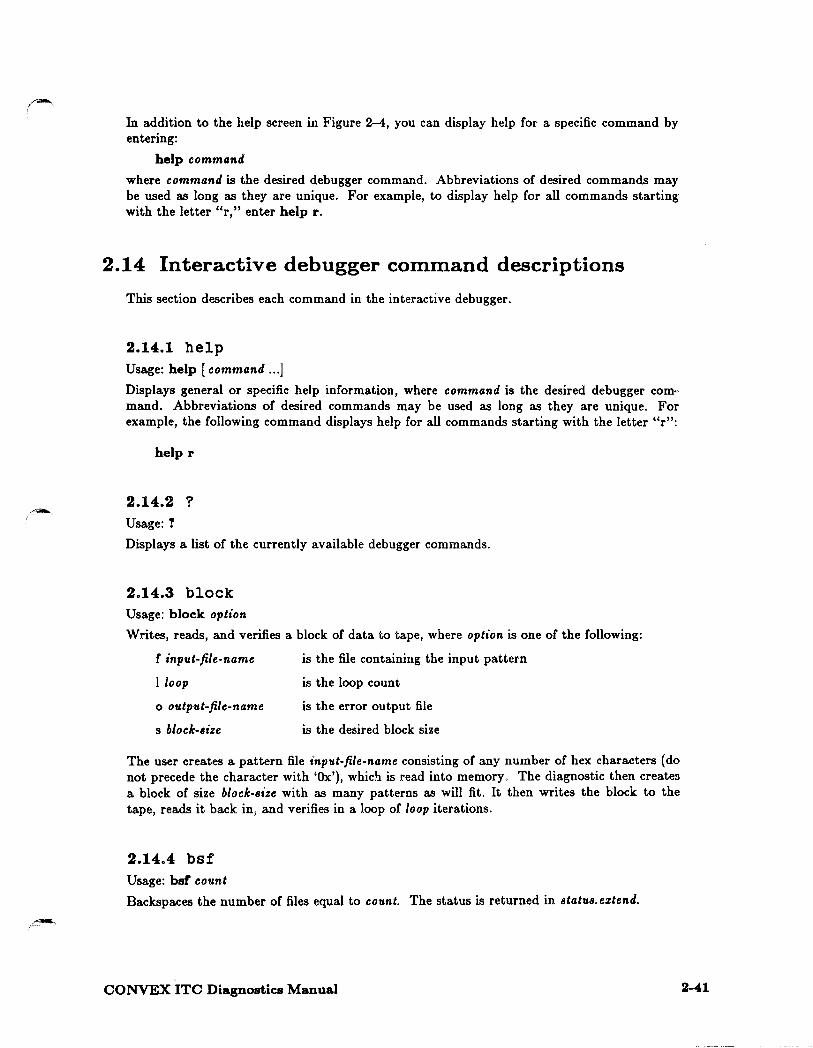
In addition to the help screen in Figure 2-4, you can display help for a specific command by entering:
help command
where command is the desired debugger command. Abbreviations of desired commands may be used as long as they are unique. For example, to display help for all commands starting with the letter "r," enter help r.
2.14 Interactive debugger command descriptions
This section describes each command in the interactive debugger.
2.14.1 help Usage: help [command ... ]
Displays general or specific help information, where command is the desired debugger command. Abbreviations of desired commands may be used as long as they are unique. For example, the following command displays help for all commands starting with the letter "r":
helpr
2.14.2 ? Usage:?
Displays a list of the currently available debugger commands.
2.14.3 block Usage: block option
Writes, reads, and verifies a block of data to tape, where option is one of the following:
f input-file-name
l loop
o output-file-name
s block-size
is the file containing the input pattern
is the loop count
is the error output file
is the desired block size
The user creates a pattern file input-file-name consisting of any number of hex characters (do not precede the character with 'Ox'), which is read into memory. The diagnostic then creates a block of size block-size with as many patterns as will fit. It then writes the block to the tape, reads it back in, and verifies in a loop of loop iterations.
2.14.4 bsf Usage: bsl count
Backspaces the number of files equal to count. The status is returned in status. eztend.
CONVEX ITC Diagnostics Manual 2-41

2.14.5 bsr Usage: bsr count
Backspaces the number of records equal to count. The status is returned in status.eztend.
2.14.6 Cd Usage: cd [directory]
Changes to another directory, where directory is any valid directory path. IC directory is omitted, the default path is $HOME or / if $HOME is not set.
2.14.7 connect Usage: connect
Connects to tape drive. This command enables the physical layer operations. The output is stored in status.code and status.modifier.
2.14.8 echo Usage: echo [-n J [ arg ... ]
Writes arguments separated by blanks and terminated by a newline to the display, where -n means do not echo the terminating newline character.
2.14.9 fb, f 1, fw Usage: :fb begin value [ incr [ step] J
:fb begin end value [ incr [ step J ]
fl begin value [ incr [ step] ] fl begin end value [ incr [step J] fw begin value [ incr [ step J J fw begin end value [ incr [step J ]
Fills CCU memory with specified pattern in byte-at-a-time mode (fb), halfword-at-a-time mode (fw), or word-at-a-time mode (fl), where:
• begin is the starting address.
• end is the ending address.
• incr is the fill value increment.
• step is the address increment.
• value is the initial fill value.
The first format (for example, fb begin value [ incr [step]]) stores value at address begin.
The second format (for example, fb begin end value [ incr [step] ] ) fills from the address begin up to and including address end with the value value.
IC the optional incr parameter is specified, value is incremented by incr after each fill. IC incr is followed by step, the fill address is incremented by step elements instead of the normal step of one for a byte, two for a halfword, or four for a word.
2-42 CONVEX ITC Diagnostics Manual

The following examples illustrate the use of these commands.
1. ft eoooooo 12945678 This command stores one longword (32 bits) of value Ox12345678 at main memory address Ox200000.
2. ft eooooo,od1000 o This command zeroes 1000 longword (32-bit) locations starting at main memory address Ox200000.
3. fb eooooo,od40 10 4 e This command fills 40 even bytes starting at CCU address Ox200000 with a value that begins at ten and increments by four each time.
2.14.10 ffb, ffl, ffw Usage: :fib begin value [ incr [ atep] ]
:fib begin end value [ incr [step] ] [incr [step]]
:ftl begin value [ incr [step] ] [incr [step]] :ftl begin end value [ incr [step]] [incr [step]]
:ffw begin value [ incr [ atep] ] [incr [step]] :ffw begin end value [ incr [step] ] [incr [step]]
Fills main memory with specified pattern in byte-at-a-time mode (fib), halfword-at-a-time mode (ffw), or word-at-a-time mode (fH)where:
• begin is the starting address.
• end is the ending address.
• value is the initial fill value.
• incr is the fill value increment.
• step is the address increment.
The first format (e.g., ffb begin value) stores value at address begin. The second format (e.g., ffb begin end value [ incr [step]]) fills from the address begin up to and including address end with the value value.
H the optional incr parameter is specified, value is incremented by incr after each fill. H incr is followed by step, the fill address is incremented by step elements instead of the normal step of one for a byte, two for a halfword, or four for a word.
2.14.11 fsf Usage: fsf count
Spaces the number of files in the forward direction equal to count. The status is returned in status. extend.
CONVEX ITC Diagnostics Manual 2-43

2.14.12 fsr Usage: far count
Spaces the number of records in the forward direction equal to count. The status is returned in atatua. extend.
2.14.13 1dent1fy Usage: identify
Displays the firmware revision number, the engineering rev1s1on number, and the day, month, and year in which the firmware in the PROM was generated.
2.14.14 1u Usage: iu
Performs an "attach,, to the tape unit. The output is stored in atatua.code and atatua. extend.
2.14.Ui mb, mw, ml Usage: mb begin [ end [ atep] ]
mw begin [ end [ atep] ] ml begin [end [ atep J ]
Displays and/or modifies CCU address space in byte-at-a-time mode (mb), halfword-at-a-time mode (mw), or word-at-a-time mode (ml), where:
• begin is the starting address.
• end is the ending address.
• atep is the address increment (if omitted, default value is access size).
If end is omitted, the debugger enters an interactive mode that allows modification of memory. The following list gives the valid responses while in interactive mode:
[ <value>] Write optional <value> to current address, advance to next address
[<value>]= Write optional <value> to current address, and stay at the present address (reread)
[ <value>]" [NJ Write optional <value> to current address, move to address N (address 0 if Nis omitted)
[ <value>]+[ NJ Write optional <value> to current address, advance to the next address (N addresses, if N is specified}
[ <value>]-[ NJ Write optional <value> to current address, back up to the previous address (N addresses, if N is specified)
[ <value> ]q Write optional <value> to current address, exit interactive mode
2-44 CONVEX ITC Diagnostics Manual

Multiple commands may be specified on the same line. A comma or space may be used to separate the commands or value as shown in the following example:
Debug Mode-> ml cOOOOO <CCU: OOcOOOOO> = le OO=ff',lq
OO=ff,lq is an example of executing multiple commands on the same line. This sequence displays the word value at IDC address cOOOOO and allows the operator to modify this value. The operator's response modifies the word to 0, rereads and displays the new value at cOOOOO, modifies the value again to Oxff, skips to address cOOOOO, modifies its value to Oxl, then exits the interactive mode.
2.14.16 mmb , mmw, mml Usage: mmb begin [ end [ atep J ]
mmw begin [ end [ atep J J
mml begin [ end [ atep J ]
Displays and/or modifies main memory address space in byte-at-a-time mode (mmb),' halfword-at-a-time mode (mmw), or word-at-a-time mode (mml), where:
• begin is the starting main memory address.
• end is the ending main memory address.
• atep is the address increment (if omitted, default value is access size).
If end is omitted, the debugger enters an interactive mode that allows modification of memory. The following list gives the valid responses while in interactive mode:
[<value> J Write optional <value> to current address, advance to next address.
[ <value>]= Write optional <value> to current address, and stay at the present address (reread).
[ <value> J A [NJ Write optional <value> to current address, move to address N (address 0 if Nis omitted).
[<value> ]+[NJ Write optional <value> to current address, advance to the next address (N addresses, if N is specified).
[ <value>]-[ N] Write optional <value> to current address, back up to the previous address (N addresses, if N is specified).
[ <value> ]q Write optional <value> to current address, exit interactive mode.
Multiple commands may be specified on the same line. A comma or space may be used to separate the commands or values as shown in the following example:
Debug mode -> mmb c03fcl <Ma.in-Mem:c03fc1> = le OO=ff',lq
le OO=ff,lq is an example of executing multiple commands on the same line. This sequence modifies the byte at main memory address c03fcl to 0, rereads and displays the new value, modifies the byte to Oxff, skips to address Oxc03fc2 and modifies it to a Oxl, and then quits interactive mode.
CONVEX ITC Diagnostics Manual 2-45

2.14.17 pause Usage: paW18 [ -n J [ aeconda J
Waits for specified amount of time or for a (RETURN) iC the time is omitted, where -n means do not echo the pause message and aeconda specifies the number of seconds to pause.
2.14.18 quit Usage: quit
Exits the interactive debugger and continues to the next single step point, if applicable.
2.14.19 rewind Usage: rewind
Rewinds tape unit with default time-out value or 60 seconds.
2.14.20 rphys Usage: rphya 6yte_count [pattern]
Reads the current record on tape, where 6yte_count specifies the number of bytes to read Crom the selected tape unit. 6yte_count also returns the actual number or bytes read upon completion or the command. pattern is an optional 32-bit pattern used to verify data read Crom the tape. The current tape status is returned in atatua. eztend.
2.14.21 status Usage: status
Returns the current tape status in atatua. eztend.
2.14.22 uni tclr Usage: unitclr
Clears the error status of a tape unit. The current tape status is returned in atatua. eztend.
2.14.23 unload Usage: unload
Ejects the cartridge tape and unloads the selected tape unit.
2.14.24 weof Usage: weof count
Writes the end-of-file (EOF) mark to tape, where count is the number of EOF marks to write to the tape.
2-48 CONVEX ITC Diagnostics Manual
~\ '

~ I
\ 2.14.25 wphys Usage: wphys byte_count [pattern]
Writes a record on tape equal to byte_coimt. pattern is an optional 32-bit pattern written repeatedly on the tape during the write process. "·'; ''
P ·r ~~'\ ~ .. ~ i. ~·- :.i
,.,::•~ 1~: ~;;..tJ,:., ~~{
'' "'''\' j ,,;; S•;!H !ff< I
.. 'f 0 .J
CONVEX ITC Diagnostics Manual 2-47

S'.-1 ! :~~ l
:.r ;,.·7,'
-~ ~- 'ii.· 11 I l.
'.-i -.
r THIS PAGE INTENTIONALLY LEFT BLANK
CONVEX ITC Diagnostics Manual

Symbol ? debugger command 2-41 I interactive command 2-29
A Associated documents, bow to order xii Associated documents, listed xi
B banner interactive command 2-29 base interactive command 2-30 block debugger command 2-41 Board tests 2-19 boot_db file 2-4 bsf debugger command 2-41 bsr debugger command 2-42
c -c interactive command 2-31
Index
Canada, reporting problems from, telephone number for xii
Cautions, described xi cd debugger command 2-42 Cl88S 0 test descriptions 2-9 Cl88S 1 subtest descriptions 2-19 Class 2 subtest descriptions 2-23 Class 4 subtest descriptions 2-24 Class 5 subtest descriptions 2-27 Class descriptions 2-8 Command scripts, user-created 1-1 Commands, interactive, I 2-29 Commands, interactive, banner 2-29 Commands, interactive, base 2-30 Commands, interactive, -c 2-31 Commands, interactive, debug 2-32 Commands, interactive, described 2-28 Commands, interactive, flags 2-32 Commands, interactive, help 2-33 Commands, interactive, ini t 2-33 Commands, interactive, log 2-33 Commands, interactive, man 2-34 Commands, interactive, Prt err 2-34 Commands, interactive, qui f; 2-34 Commands, interactive, -s 2-35 Commands, interactive, save 2-35 Commands, interactive, set 2-35 Commands, interactive, state 2-38 Commands, interactive, trace 2-38 Commands, interactive, trout 2-39 connect debugger command 2-42 Continental U.S., reporting problems from, telephone
number for xii CONVEX, address, for ordering documents xii
D Data memory tests 2-9 Data path subtest& 2-23 debug interactive command 2-32 Debugger, interactive, ? 2-41 Debugger, interactive, block 2-41 Debugger, interactive, bsf 2-41 Debugger, interactive, bsr 2-42 Debugger, interactive, cd 2-42 Debugger, interactive, command descriptions 2-41 Debugger, interactive, connect 2-42 Debugger, interactive, described 2-39 Debugger, interactive, echo 2-42 Debugger, interactive, fb, fl. fw 2-42 Debugger, interactive, ffb. f fl. ffw 2-43
Debugger, interactive, fsf 2-43 Debugger, interactive, fsr 2-44 Debugger, interactive, help 2-41 Debugger, interactive, help screen 2-39 Debugger, interactive, identify 2-44 Debugger, interactive, iu 2-44 Debugger, interactive, mb. mw, ml 2-44 Debugger, interactive, mmb. mmw. mml 2-45 Debugger, interactive, pause 2-46 Debugger, interactive, quit 2-46 Debugger, interactive, rewind 2-46 Debugger, interactive, rphys 2-46 Debugger, interactive, status 2-46 Debugger, interactive, uni tclr 2-46 Debugger, interactive, unload 2-46 Debugger, interactive, weof 2-46 Debugger, interactive, wphys 2-47 Diagnostic environment, overview 1-1 Diagnostic shell. See dshell 1-1 Diagnostics, selecting 1-1 dshell, commands, summarized 1-2 dshell, commands, syntax 1-3 dshell, functions 1-1 dshell, introduction 1-1
E echo debugger command 2-42 Error messages, selecting 1-1 Exception subtest& 2-27
F fb, fl, fw debugger command 2-42 ffb. f fl, ffw debugger command 2-43 Files, test outputs to 1-1 flags interactive command 2-32 fsf debugger command 2-43 fsr debugger command 2-44
H Hardware logic tests 2-19 Hardware requirements 2-2 help debugger command 2-41 Help for dev6610 prompts 2-5 help interactive command 2-33
I identify debugger command 2-44 in1 t interactive command 2-33 Initialization sequence, described 2-4 Initialization sequence, prompt explanations 2-6 Initialization sequence, test parameter menu 2-4 Initialization sequence, test parameter menu, illustrated
2-4 Initialization sequence, test parameter summary, illus-
trated 2-8 Integrated tape channel subsystem test 2-1 Interactive commands, described 2-28 Internal diagnostic tests 2-10 i u debugger command 2-44
L log interactive command 2-33 Loopback subtest& 2-23
lndex-1

Index
M man interactive command 2-34 mb. raw, ml debugger command 2-44 Memory tests, data 2-9 Memory tests, program 2-9 mmb. mmw, mml debugger command 2-45
N Notational conventions, discussed xi Notes, described xi
0 Overview, diagnostic environment 1·1 Overview, dshall l·l Overview, integra.ted tape cha.nnel subsystem test 2-1
p
pause debugger command 2-46 PBUS interl'ace logic tests 2-0 Program memory tests 2-11 Prt _ orr interactive command 2-34
Q quit debugger command 2-46 quit interactive command 2-34
R Read/write subtest.a 2-24 Reporting problems xii Revision sheet 3 rewind debugger command 2-46 rpb7s debugger command 2-46
s -s interactive command 2-35 save interactive command 2-35 Screens, test outputs to l· l set interactive command 2-35 stgte interactive command 2-38 status debugger command 2-46
T TAC, reporting problems to xii Tape drive exception subtest& 2-27 Tape motion subtest& 2-24 Technical assistance, discussed xii test command options 2-3 Test invocation, initial 2-3 Test invocation, test command 2-3 Test. parameter menu 2-4 Test parameter summary 2-8 Tests, options, selecting 1-1 Tests, output, selecting 1-1 trace interactive command 2-38 Trouble reports xii trout interactive command 2-30
lndex-2
u uni tclr debugger command 2-46 unload debugger command 2-46 U.S., reporting problems from, telephone number for xii
w Warnings, described xi weof debugger command 2-46 wpbys debugger command 2-47
~ ..