coolant checking cool - west texas motoring …wtxmc.org/minicooperdocs/cooling and...
TRANSCRIPT

2002-2008 ENGINE
Cooling & Turbocharger System - Repair Instructions - Cooper S
COOLANT CHECKING COOL
17 00... FOLLOW INSTRUCTIONS FOR WORKING ON COOLING SYSTEM
Recycling:
Catch and dispose of drained coolant.
Comply with the waste disposal regulations applicable in the relevant countries.
17 00 000 FITTING GUARD FOR INTERCOOLER
Special tools required:
11 8 480
Fit special tool 11 8 480.
WARNING: Scalding hazard! Work on the cooling system may only be carried out on the engine after it has cooled down.
IMPORTANT: When working on oil, coolant or fuel lines, make sure no oil, coolant or fuel drips onto the alternator. Cover alternator with suitable material. Otherwise there may be alternator malfunctions.
IMPORTANT: Only open the cooling system when the coolant is no longer hot. Air may enter the cooling system if it is opened while the coolant is still hot.This may cause the engine to overheat and result in permanent damage.
NOTE: Before beginning repair work in the engine compartment, fit guard 11 8 480 for intercooler.
IMPORTANT: The guard for the intercooler must be removed when the engine is running.Driving with the intercooler guard fitted may result in engine damage.
2006 MINI Cooper
2002-2008 ENGINE Cooling & Turbocharger System - Repair Instructions - Cooper S
2006 MINI Cooper
2002-2008 ENGINE Cooling & Turbocharger System - Repair Instructions - Cooper S
Microsoft
Tuesday, February 16, 2010 11:50:57 AM Page 1 © 2005 Mitchell Repair Information Company, LLC.
Microsoft
Tuesday, February 16, 2010 11:51:01 AM Page 1 © 2005 Mitchell Repair Information Company, LLC.

Fig. 1: Installing Special Tool Courtesy of BMW OF NORTH AMERICA, INC.
The yellow ribbed belt must hang down over the front bumper to remind all personnel that the intercooler guard is fitted (e.g. when the engine hood/bonnet is closed).
17 00 005 DRAINING AND ADDING COOLANT (COOPER S)
Recycling:
Catch and dispose of drained coolant.
Comply with the waste disposal regulations applicable in the relevant countries.
WARNING: Work on the cooling system may only be carried out on the engine after it has cooled down.
2006 MINI Cooper
2002-2008 ENGINE Cooling & Turbocharger System - Repair Instructions - Cooper S
Microsoft
Tuesday, February 16, 2010 11:50:57 AM Page 2 © 2005 Mitchell Repair Information Company, LLC.

Draining coolant:
Screw off pressure relief cap (1) on expansion tank.
Fig. 2: Removing Pressure Relief Cap Courtesy of BMW OF NORTH AMERICA, INC.
Remove underbody protection. Refer to 51 47 490 REMOVING AND INSTALLING/REPLACING FRONT UNDERBODY PROTECTION (ENGINE) .
Disconnect lower hose connection on radiator (1).
NOTE: Follow instructions for working on cooling system. Refer to 17 00... Follow instructions for working on cooling system. After adding coolant, vent cooling system and check for leaks. Refer to 17 00 039 Bleeding cooling system and checking for water leaks.
2006 MINI Cooper
2002-2008 ENGINE Cooling & Turbocharger System - Repair Instructions - Cooper S
Microsoft
Tuesday, February 16, 2010 11:50:57 AM Page 3 © 2005 Mitchell Repair Information Company, LLC.

Fig. 3: Disconnecting Coolant Hose Courtesy of BMW OF NORTH AMERICA, INC.
Drain, catch and dispose of coolant.
Reattach coolant hose (1).
Release vent screw (1) in heating distributor pipe.
2006 MINI Cooper
2002-2008 ENGINE Cooling & Turbocharger System - Repair Instructions - Cooper S
Microsoft
Tuesday, February 16, 2010 11:50:57 AM Page 4 © 2005 Mitchell Repair Information Company, LLC.

Fig. 4: Releasing Heating Distributor Pipe Vent Screw Courtesy of BMW OF NORTH AMERICA, INC.
Tightening torque 17 00 1AZ. Refer to COOLING SYSTEM - TIGHTENING TORQUES .
Release vent screw (1) in upper radiator hose.
The cooling system is vented during filling.
2006 MINI Cooper
2002-2008 ENGINE Cooling & Turbocharger System - Repair Instructions - Cooper S
Microsoft
Tuesday, February 16, 2010 11:50:57 AM Page 5 © 2005 Mitchell Repair Information Company, LLC.

Fig. 5: Releasing Upper Radiator Hose Vent Screw Courtesy of BMW OF NORTH AMERICA, INC.
Adding coolant:
Pour coolant into expansion tank (1).
2006 MINI Cooper
2002-2008 ENGINE Cooling & Turbocharger System - Repair Instructions - Cooper S
Microsoft
Tuesday, February 16, 2010 11:50:57 AM Page 6 © 2005 Mitchell Repair Information Company, LLC.

Fig. 6: Filling Expansion Tank Courtesy of BMW OF NORTH AMERICA, INC.
Tighten down vent screws as soon as coolant emerges.
Tightening torque 17 00 2AZ. Refer to COOLING SYSTEM - TIGHTENING TORQUES .
Fill expansion tank up to maximum level.
Start engine and run at idle speed. Fill expansion tank if liquid level drops.
Continue running engine until liquid level stops dropping.
Switch off engine.
Fill expansion tank up to maximum level.
2006 MINI Cooper
2002-2008 ENGINE Cooling & Turbocharger System - Repair Instructions - Cooper S
Microsoft
Tuesday, February 16, 2010 11:50:57 AM Page 7 © 2005 Mitchell Repair Information Company, LLC.

Use only approved coolant, refer to BMW operating fluids in Main Group 17.
17 00 009 CHECKING COOLING SYSTEM FOR LEAKS (W11)
Special tools required:
17 0 002
17 0 008
17 0 051
17 0 052
Checking pressure drop in cooling system:
Remove cap from expansion tank.
Connect special tool 17 0 051 to expansion tank. Connect special tool 17 0 002.
NOTE: Before filling, turn on ignition and set heating control to maximum temperature.Set fan to sow setting. Add coolant slowly.
WARNING: Risk of burning and scalding! Only perform this work after engine has cooled down.
2006 MINI Cooper
2002-2008 ENGINE Cooling & Turbocharger System - Repair Instructions - Cooper S
Microsoft
Tuesday, February 16, 2010 11:50:57 AM Page 8 © 2005 Mitchell Repair Information Company, LLC.

Fig. 7: Connecting Special Tool To Expansion Tank Courtesy of BMW OF NORTH AMERICA, INC.
Pressurize cooling system to 1.5 bar and wait approx. 2 minutes.
Cooling system is tight if pressure drop does not exceed 0.1 bar.
Checking pressure relief valve in cap:
Remove rubber seal from special tool 17 0 002.
Connect special tools 17 0 052, 17 0 008 and 17 0 002 to cap.
2006 MINI Cooper
2002-2008 ENGINE Cooling & Turbocharger System - Repair Instructions - Cooper S
Microsoft
Tuesday, February 16, 2010 11:50:57 AM Page 9 © 2005 Mitchell Repair Information Company, LLC.

Fig. 8: Connecting Special Tools To Pressurize Cap Courtesy of BMW OF NORTH AMERICA, INC.
Pressurize cap.
Opening gauge pressure must be 0.89 - 1.20 bar.
17 00 010 CHECKING FOR LEAKS BETWEEN COOLING SYSTEM AND COMBUSTION CHAMBER
R50:
Remove pressure cap from fill tower.
CAUTION: Checking for leaks while the engine is running creates the risk of engine overheating. Observe coolant temperature.
2006 MINI Cooper
2002-2008 ENGINE Cooling & Turbocharger System - Repair Instructions - Cooper S
Microsoft
Tuesday, February 16, 2010 11:50:57 AM Page 10 © 2005 Mitchell Repair Information Company, LLC.

Check for leaks with CO2 leak tester.
R53:
Remove pressure cap from expansion tank.
Check for leaks with CO2 leak tester.
Fig. 9: Checking For Leaks Courtesy of BMW OF NORTH AMERICA, INC.
Follow equipment manufacturer's operating instructions.
17 00 039 BLEEDING COOLING SYSTEM AND CHECKING FOR WATER LEAKS
WARNING: Danger of scalding - only remove cover when engine has cooled down.
2006 MINI Cooper
2002-2008 ENGINE Cooling & Turbocharger System - Repair Instructions - Cooper S
Microsoft
Tuesday, February 16, 2010 11:50:57 AM Page 11 © 2005 Mitchell Repair Information Company, LLC.

Checking coolant level
Allow engine to cool down before checking coolant level.
Coolant temperature must not be more than 30 °C.
If ambient temperature exceeds 30°C, wait until engine has cooled down to ambient temperature.
Use only recommended coolant, refer to BMW Operating Fluids .
Check coolant level and top up if necessary.
Add coolant, refer to 17 00 005 Draining and adding coolant (COOPER S)
Checking cooling system for water leaks, refer to 17 00 009 Checking cooling system for leaks (W11)
ENGINE RADIATOR WITH ATTACHMENT
17 11 000 REMOVING AND INSTALLING RADIATOR
Necessary preliminary tasks:
Switch off ignition
Drain coolant, refer to 17 00 005 Draining and adding coolant (COOPER S)
Remove front carrier, refer to 51 11 050 REMOVING AND INSTALLING/REPLACING CARRIER FOR FRONT BUMPER TRIM
Remove oil cooler, if fitted (ECVT only)
Remove upper radiator hose
Remove retaining screws (1) of condenser and lift condenser out of fixture/retaining lug (2).
WARNING: Danger of scalding! Only carry out work on the cooling system after the engine has cooled down!
IMPORTANT: Make sure without fail that coolant hoses are correctly routed, risk of damage by sharp edges or abrasion.
2006 MINI Cooper
2002-2008 ENGINE Cooling & Turbocharger System - Repair Instructions - Cooper S
Microsoft
Tuesday, February 16, 2010 11:50:57 AM Page 12 © 2005 Mitchell Repair Information Company, LLC.

Fig. 10: Removing Condenser Courtesy of BMW OF NORTH AMERICA, INC.
Work carefully so as not to damage connected lines.
Remove upper radiator hose.
2006 MINI Cooper
2002-2008 ENGINE Cooling & Turbocharger System - Repair Instructions - Cooper S
Microsoft
Tuesday, February 16, 2010 11:50:57 AM Page 13 © 2005 Mitchell Repair Information Company, LLC.

Fig. 11: Removing Radiator Retaining Pins Courtesy of BMW OF NORTH AMERICA, INC.
Remove retaining pins (1) of radiator.
Tilt upper radiator forwards.
2006 MINI Cooper
2002-2008 ENGINE Cooling & Turbocharger System - Repair Instructions - Cooper S
Microsoft
Tuesday, February 16, 2010 11:50:57 AM Page 14 © 2005 Mitchell Repair Information Company, LLC.

Fig. 12: Disconnecting Wiring Harness From Fan Relay Block Courtesy of BMW OF NORTH AMERICA, INC.
Disconnect wiring harness from fan relay block (1).
Lift radiator out of lower fixtures (1).
2006 MINI Cooper
2002-2008 ENGINE Cooling & Turbocharger System - Repair Instructions - Cooper S
Microsoft
Tuesday, February 16, 2010 11:50:57 AM Page 15 © 2005 Mitchell Repair Information Company, LLC.

Fig. 13: Removing Radiator From Lower Fixtures Courtesy of BMW OF NORTH AMERICA, INC.
17 11 001 REPLACING RADIATOR
For procedure.
17 11 031 REMOVING AND INSTALLING/REPLACING FAN COWL
Necessary preliminary tasks:
Remove fan cowl with electric fan, refer to 17 11 035 Removing and installing/replacing fan cowl with electric fan (W10, W11)
IMPORTANT: Make sure without fail that coolant hoses are correctly routed, risk of damage by sharp edges or abrasion.
2006 MINI Cooper
2002-2008 ENGINE Cooling & Turbocharger System - Repair Instructions - Cooper S
Microsoft
Tuesday, February 16, 2010 11:50:57 AM Page 16 © 2005 Mitchell Repair Information Company, LLC.

Unscrew nut (1).
Fig. 14: Removing Fan Blade Nut Courtesy of BMW OF NORTH AMERICA, INC.
Tightening torque 17 11 1AZ. Refer to COOLING SYSTEM - TIGHTENING TORQUES .
Undo screws (1) for fan motor and screws (2) for series resistor block.
NOTE: Nut (1) for fan blade has a left-hand thread.
2006 MINI Cooper
2002-2008 ENGINE Cooling & Turbocharger System - Repair Instructions - Cooper S
Microsoft
Tuesday, February 16, 2010 11:50:57 AM Page 17 © 2005 Mitchell Repair Information Company, LLC.

Fig. 15: Removing Components Courtesy of BMW OF NORTH AMERICA, INC.
Remove fan motor, series resistor block and fan shroud.
Installation:
Fit wiring loom correctly.
If fitted, do not remove metal tabs (balance weight) on fan wheel (imbalance).
Tightening torque 17 11 2AZ. Refer to COOLING SYSTEM - TIGHTENING TORQUES .
17 11 035 REMOVING AND INSTALLING/REPLACING FAN COWL WITH ELECTRIC FAN (W10, W11)
Necessary preliminary tasks:
2006 MINI Cooper
2002-2008 ENGINE Cooling & Turbocharger System - Repair Instructions - Cooper S
Microsoft
Tuesday, February 16, 2010 11:50:57 AM Page 18 © 2005 Mitchell Repair Information Company, LLC.

Remove radiator, refer to 17 11 000 Removing and installing radiator
Unclip fan housing (1) on radiator (2) and move upward.
Fig. 16: Removing Fan Cowl Courtesy of BMW OF NORTH AMERICA, INC.
Remove fan cowl with electric fan.
OIL COOLER
17 21 500 FLUSHING OIL COOLER WITH LINES (AUTOMATIC TRANSMISSION)
Special tools required:
IMPORTANT: Make sure without fail that coolant hoses are correctly routed, risk of damage by sharp edges or abrasion.
2006 MINI Cooper
2002-2008 ENGINE Cooling & Turbocharger System - Repair Instructions - Cooper S
Microsoft
Tuesday, February 16, 2010 11:50:57 AM Page 19 © 2005 Mitchell Repair Information Company, LLC.

17 2 018
17 2 019
Procedure:
Automatic transmission removed.
Connect appropriate adapters (see description below) to oil lines exiting from automatic transmission.
Connect the connecting line 17 2 019 from the oil collection unit with the quick-release coupling.
Connect drain line 17 2 018 using quick-release coupling.
Feed open end of drain line into a suitable collection container.
Using oil collection unit, flush approx. 1 liter of transmission fluid (refer to ) through oil lines and oil cooler.
Reposition quick -release couplings.
Flush oil lines/oil cooler in opposite direction with approx. 1 liter of transmission fluid (refer to BMW Service Operating Fluids ).
Disconnect quick -release couplings, remove adapters.
NOTE: Carry out the work steps listed when: Fitting a new or replacement transmission Flushing can only be carried out with the automatic transmission removed.
NOTE: Dispose of flushing oil properly; do not under any circumstances reuse it.
2006 MINI Cooper
2002-2008 ENGINE Cooling & Turbocharger System - Repair Instructions - Cooper S
Microsoft
Tuesday, February 16, 2010 11:50:57 AM Page 20 © 2005 Mitchell Repair Information Company, LLC.

Fig. 17: Arrangement Of Flushing Device For Transmissions A5S 310Z, A5S 560Z, A5S 360R/390R, A4S 200R, A5S 325Z, GA6HP26Z Courtesy of BMW OF NORTH AMERICA, INC.
2006 MINI Cooper
2002-2008 ENGINE Cooling & Turbocharger System - Repair Instructions - Cooper S
Microsoft
Tuesday, February 16, 2010 11:50:57 AM Page 21 © 2005 Mitchell Repair Information Company, LLC.

Fig. 18: Arrangement Of Flushing Device For Transmission A4S 310R) Courtesy of BMW OF NORTH AMERICA, INC.
2006 MINI Cooper
2002-2008 ENGINE Cooling & Turbocharger System - Repair Instructions - Cooper S
Microsoft
Tuesday, February 16, 2010 11:50:57 AM Page 22 © 2005 Mitchell Repair Information Company, LLC.

Fig. 19: Arrangement Of Flushing Device For Transmission A4S 300J Courtesy of BMW OF NORTH AMERICA, INC.
2006 MINI Cooper
2002-2008 ENGINE Cooling & Turbocharger System - Repair Instructions - Cooper S
Microsoft
Tuesday, February 16, 2010 11:50:57 AM Page 23 © 2005 Mitchell Repair Information Company, LLC.

Fig. 20: Arrangement Of Flushing Device For Transmission A5S 440Z Courtesy of BMW OF NORTH AMERICA, INC.
OIL COOLER WITH LINES
17 21 500 FLUSHING OIL COOLER WITH LINES (AUTOMATIC TRANSMISSION)
2006 MINI Cooper
2002-2008 ENGINE Cooling & Turbocharger System - Repair Instructions - Cooper S
Microsoft
Tuesday, February 16, 2010 11:50:57 AM Page 24 © 2005 Mitchell Repair Information Company, LLC.

For procedure, refer to 17 21 500 Flushing oil cooler with lines (automatic transmission).
CHARGE AIR COOLER WITH MOUNT
17 51 000 REMOVING AND INSTALLING/REPLACING INTERCOOLER
Unscrew mounting bolts (1) from intercooler cover.
Fig. 21: Removing Intercooler Cover Courtesy of BMW OF NORTH AMERICA, INC.
Remove intercooler cover (2).
Tightening torque 17 51 1AZ. Refer to COOLING SYSTEM - TIGHTENING TORQUES .
IMPORTANT: Intercooler sealing rings may only be installed in clean and dry condition.Do not lubricate seals.
2006 MINI Cooper
2002-2008 ENGINE Cooling & Turbocharger System - Repair Instructions - Cooper S
Microsoft
Tuesday, February 16, 2010 11:50:57 AM Page 25 © 2005 Mitchell Repair Information Company, LLC.

Remove screws (1) from brackets for sealing rings and remove upper brackets (2).
Fig. 22: Removing Brackets Courtesy of BMW OF NORTH AMERICA, INC.
Remove screws (3) from brackets for intercooler and remove brackets (4).
Tightening torque 17 51 2AZ. Refer to COOLING SYSTEM - TIGHTENING TORQUES .
Tightening torque 17 51 3AZ. Refer to COOLING SYSTEM - TIGHTENING TORQUES .
Remove intercooler from right side.
2006 MINI Cooper
2002-2008 ENGINE Cooling & Turbocharger System - Repair Instructions - Cooper S
Microsoft
Tuesday, February 16, 2010 11:50:57 AM Page 26 © 2005 Mitchell Repair Information Company, LLC.

Fig. 23: Removing Intercooler From Right Side Courtesy of BMW OF NORTH AMERICA, INC.
Installation:
Make sure intercooler sealing rings are correctly seated.
Secure sealing ring holders (1) fitted with threads to underside.
NOTE: Inspect sealing rings for cracks and damage and replace if necessary.
2006 MINI Cooper
2002-2008 ENGINE Cooling & Turbocharger System - Repair Instructions - Cooper S
Microsoft
Tuesday, February 16, 2010 11:50:58 AM Page 27 © 2005 Mitchell Repair Information Company, LLC.

Fig. 24: Securing Sealing Ring Holders Courtesy of BMW OF NORTH AMERICA, INC.
17 51 080 REMOVING AND INSTALLING/REPLACING TURBOCHARGER EXHAUST PIPE (RIGHT)
Remove left turbocharger exhaust pipe. Refer to 17 51 085 Removing and installing/replacing pipe between intercooler and intake manifold (left).
Remove intake manifold. Refer to 11 61 051 REMOVING AND INSTALLING INTAKE MANIFOLD (COOPER S) .
Release bolts (1) and remove turbocharger exhaust pipe (2).
2006 MINI Cooper
2002-2008 ENGINE Cooling & Turbocharger System - Repair Instructions - Cooper S
Microsoft
Tuesday, February 16, 2010 11:50:58 AM Page 28 © 2005 Mitchell Repair Information Company, LLC.

Fig. 25: Removing Turbocharger Exhaust Pipe Courtesy of BMW OF NORTH AMERICA, INC.
Tightening torque 17 51 4AZ. Refer to COOLING SYSTEM - TIGHTENING TORQUES .
Install new gasket (1) as shown so that TOP lettering (2) is can be read.
2006 MINI Cooper
2002-2008 ENGINE Cooling & Turbocharger System - Repair Instructions - Cooper S
Microsoft
Tuesday, February 16, 2010 11:50:58 AM Page 29 © 2005 Mitchell Repair Information Company, LLC.

Fig. 26: Installing Gasket Courtesy of BMW OF NORTH AMERICA, INC.
17 51 085 REMOVING AND INSTALLING/REPLACING PIPE BETWEEN INTERCOOLER AND INTAKE MANIFOLD (LEFT)
Disconnect battery. Refer to 12 00 DISCONNECTING AND CONNECTING BATTERY .
Remove throttle. Refer to 13 54 030 REMOVING AND INSTALLING/SEALING THROTTLE ASSEMBLY (COOPER S) .
Remove intercooler. Refer to 17 51 000 Removing and installing/replacing intercooler.
Lever out hose clamp (1) with screwdriver in direction of arrow.
2006 MINI Cooper
2002-2008 ENGINE Cooling & Turbocharger System - Repair Instructions - Cooper S
Microsoft
Tuesday, February 16, 2010 11:50:58 AM Page 30 © 2005 Mitchell Repair Information Company, LLC.

Fig. 27: Levering Out Hose Clamp Courtesy of BMW OF NORTH AMERICA, INC.
Unscrew housing retaining nuts (2).
NOTE: Illustration shows removed air duct.
2006 MINI Cooper
2002-2008 ENGINE Cooling & Turbocharger System - Repair Instructions - Cooper S
Microsoft
Tuesday, February 16, 2010 11:50:58 AM Page 31 © 2005 Mitchell Repair Information Company, LLC.

Fig. 28: Removing Housing Courtesy of BMW OF NORTH AMERICA, INC.
Remove housing (3).
Replace seal.
Tightening torque 17 51 5AZ. Refer to COOLING SYSTEM - TIGHTENING TORQUES .
Secure hose clamp (1) with special tool 13 1 511.
2006 MINI Cooper
2002-2008 ENGINE Cooling & Turbocharger System - Repair Instructions - Cooper S
Microsoft
Tuesday, February 16, 2010 11:50:58 AM Page 32 © 2005 Mitchell Repair Information Company, LLC.

Fig. 29: Securing Hose Clamp Courtesy of BMW OF NORTH AMERICA, INC.
Assemble engine.
17 51 090 REMOVING AND INSTALLING OR REPLACING TURBOCHARGER INLET PIPE
Special tools required:
11 8 401
11 8 402
Remove impact tube. Refer to 31 11 020 Removing and installing/replacing bumper bracket .
Lower front end module and attach special tools 11 8 401 and 11 8 402.
NOTE: Illustration shows removed air duct.
2006 MINI Cooper
2002-2008 ENGINE Cooling & Turbocharger System - Repair Instructions - Cooper S
Microsoft
Tuesday, February 16, 2010 11:50:58 AM Page 33 © 2005 Mitchell Repair Information Company, LLC.

Fig. 30: Attaching Special Tool Courtesy of BMW OF NORTH AMERICA, INC.
Remove pipe from intercooler to intake manifold. Refer to 17 51 085 Removing and installing/replacing pipe between intercooler and intake manifold (left).
Remove retaining bolt (1) for turbocharger inlet.
2006 MINI Cooper
2002-2008 ENGINE Cooling & Turbocharger System - Repair Instructions - Cooper S
Microsoft
Tuesday, February 16, 2010 11:50:58 AM Page 34 © 2005 Mitchell Repair Information Company, LLC.
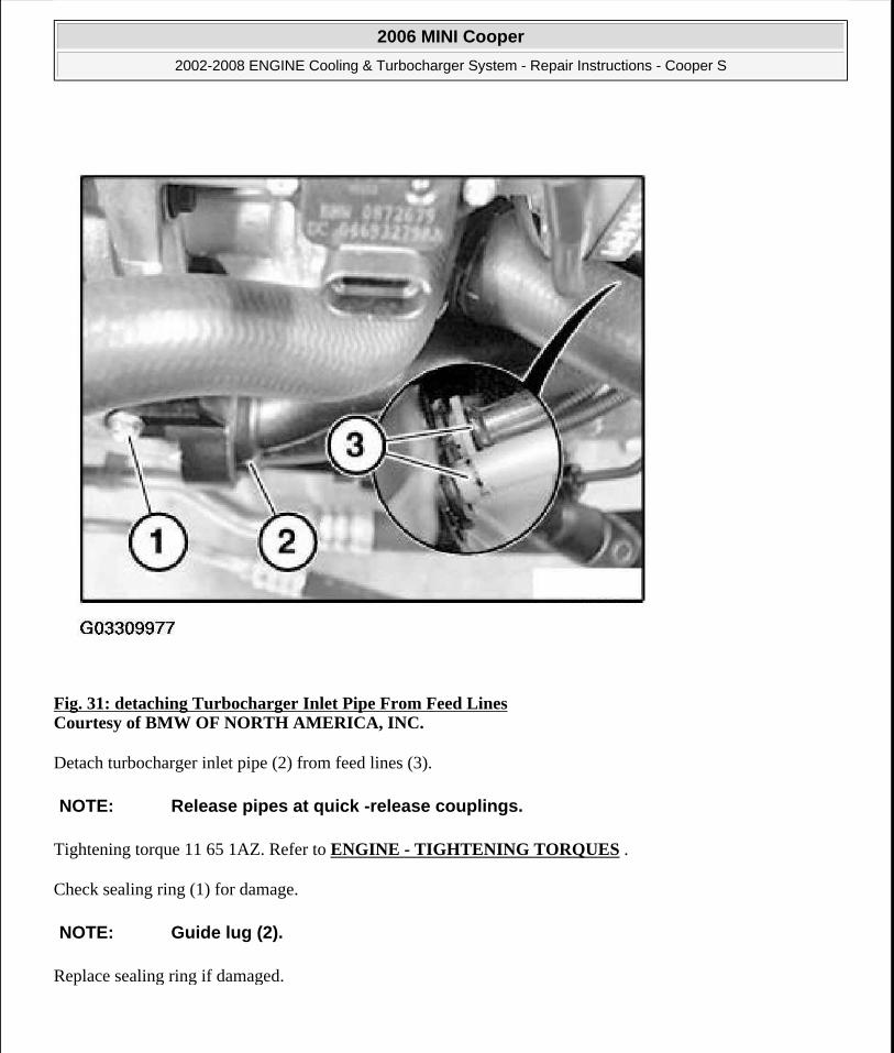
Fig. 31: detaching Turbocharger Inlet Pipe From Feed Lines Courtesy of BMW OF NORTH AMERICA, INC.
Detach turbocharger inlet pipe (2) from feed lines (3).
Tightening torque 11 65 1AZ. Refer to ENGINE - TIGHTENING TORQUES .
Check sealing ring (1) for damage.
Replace sealing ring if damaged.
NOTE: Release pipes at quick -release couplings.
NOTE: Guide lug (2).
2006 MINI Cooper
2002-2008 ENGINE Cooling & Turbocharger System - Repair Instructions - Cooper S
Microsoft
Tuesday, February 16, 2010 11:50:58 AM Page 35 © 2005 Mitchell Repair Information Company, LLC.

Fig. 32: Checking Sealing Ring Courtesy of BMW OF NORTH AMERICA, INC.
17 51 100 REMOVING AND INSTALLING/REPLACING LEFT OR RIGHT SEALING RINGS ON INTERCOOLER
Remove intercooler. Refer to 17 51 000 Removing and installing/replacing intercooler.
Unscrew retaining screws (1) of sealing ring brackets on left and right sides, remove brackets and sealing rings.
2006 MINI Cooper
2002-2008 ENGINE Cooling & Turbocharger System - Repair Instructions - Cooper S
Microsoft
Tuesday, February 16, 2010 11:50:58 AM Page 36 © 2005 Mitchell Repair Information Company, LLC.

Fig. 33: Removing Brackets & Seals Courtesy of BMW OF NORTH AMERICA, INC.
Replace sealing rings.
Tightening torque 17 51 2AZ. Refer to COOLING SYSTEM - TIGHTENING TORQUES .
Installation:
Before installing sealing ring, first place sealing ring bracket on left side of intercooler on sealing ring.
2006 MINI Cooper
2002-2008 ENGINE Cooling & Turbocharger System - Repair Instructions - Cooper S
Microsoft
Tuesday, February 16, 2010 11:50:58 AM Page 37 © 2005 Mitchell Repair Information Company, LLC.

Fig. 34: Aligning Brackets And Threads Courtesy of BMW OF NORTH AMERICA, INC.
Check that sealing rings and brackets are correctly positioned.
Pay attention to alignment of brackets and threads on underside.
17 51 104 REMOVING AND INSTALLING/REPLACING SEALING RINGS ON INTERCOOLER
Remove intercooler. Refer to 17 51 000 Removing and installing/replacing intercooler.
Remove screws (1) from brackets for sealing rings, remove brackets and sealing rings.
2006 MINI Cooper
2002-2008 ENGINE Cooling & Turbocharger System - Repair Instructions - Cooper S
Microsoft
Tuesday, February 16, 2010 11:50:58 AM Page 38 © 2005 Mitchell Repair Information Company, LLC.

Fig. 35: Removing Brackets & Seals Courtesy of BMW OF NORTH AMERICA, INC.
Replace sealing rings.
Tightening torque 17 51 2AZ. Refer to COOLING SYSTEM - TIGHTENING TORQUES .
Installation:
Before installing sealing ring, first place sealing ring bracket on left side of intercooler on sealing ring.
2006 MINI Cooper
2002-2008 ENGINE Cooling & Turbocharger System - Repair Instructions - Cooper S
Microsoft
Tuesday, February 16, 2010 11:50:58 AM Page 39 © 2005 Mitchell Repair Information Company, LLC.

Fig. 36: Aligning Brackets And Threads Courtesy of BMW OF NORTH AMERICA, INC.
Check that sealing rings and brackets are correctly positioned.
Pay attention to alignment of brackets and threads on underside (1).
2006 MINI Cooper
2002-2008 ENGINE Cooling & Turbocharger System - Repair Instructions - Cooper S
Microsoft
Tuesday, February 16, 2010 11:50:58 AM Page 40 © 2005 Mitchell Repair Information Company, LLC.