cooling of electronic equipment - kntu.ac.ir
TRANSCRIPT
C O O L I N G O F E L E C T R O N I CE Q U I P M E N T
Electronic equipment has made its way into practically every aspect ofmodern life, from toys and appliances to high-power computers. The re-liability of the electronics of a system is a major factor in the overall re-
liability of the system. Electronic components depend on the passage ofelectric current to perform their duties, and they become potential sites for ex-cessive heating, since the current flow through a resistance is accompanied byheat generation. Continued miniaturization of electronic systems has resultedin a dramatic increase in the amount of heat generated per unit volume, com-parable in magnitude to those encountered at nuclear reactors and the surfaceof the sun. Unless properly designed and controlled, high rates of heat gener-ation result in high operating temperatures for electronic equipment, whichjeopardizes its safety and reliability.
The failure rate of electronic equipment increases exponentially withtemperature. Also, the high thermal stresses in the solder joints of electroniccomponents mounted on circuit boards resulting from temperature variationsare major causes of failure. Therefore, thermal control has become increas-ingly important in the design and operation of electronic equipment.
In this chapter, we discuss several cooling techniques commonly usedin electronic equipment such as conduction cooling, natural convection andradiation cooling, forced-air cooling, liquid cooling, and immersion cooling.This chapter is intended to familiarize the reader with these techniques and putthem into perspective. The reader interested in an in-depth coverage of any ofthese topics can consult numerous other sources available, such as those listedin the references.
785
CHAPTER
15CONTENTS
15–1 Introduction and History 786
15–2 Manufacturing of ElectronicEquipment 787
15–3 Cooling Load of ElectronicEquipment 793
15–4 Thermal Environment 794
15–5 Electronics Cooling in DifferentApplications 795
15–6 Conduction Cooling 797
15–7 Air Cooling: Natural Convectionand Radiation 812
15–8 Air Cooling: Forced Convection 820
15–9 Liquid Cooling 833
15–10 Immersion Cooling 836
cen58933_ch15.qxd 9/9/2002 10:20 AM Page 785
15–1 INTRODUCTION AND HISTORYThe field of electronics deals with the construction and utilization of devicesthat involve current flow through a vacuum, a gas, or a semiconductor. Thisexciting field of science and engineering dates back to 1883, when ThomasEdison invented the vacuum diode. The vacuum tube served as the foun-dation of the electronics industry until the 1950s, and played a central role inthe development of radio, TV, radar, and the digital computer. Of the severalcomputers developed in this era, the largest and best known is the ENIAC(Electronic Numerical Integrator and Computer), which was built at the Uni-versity of Pennsylvania in 1946. It had over 18,000 vacuum tubes and occu-pied a room 7 m � 14 m in size. It consumed a large amount of power, and itsreliability was poor because of the high failure rate of the vacuum tubes.
The invention of the bipolar transistor in 1948 marked the beginning of anew era in the electronics industry and the obsolescence of vacuum tube tech-nology. Transistor circuits performed the functions of the vacuum tubes withgreater reliability, while occupying negligible space and consuming negligiblepower compared with vacuum tubes. The first transistors were made from ger-manium, which could not function properly at temperatures above 100°C.Soon they were replaced by silicon transistors, which could operate at muchhigher temperatures.
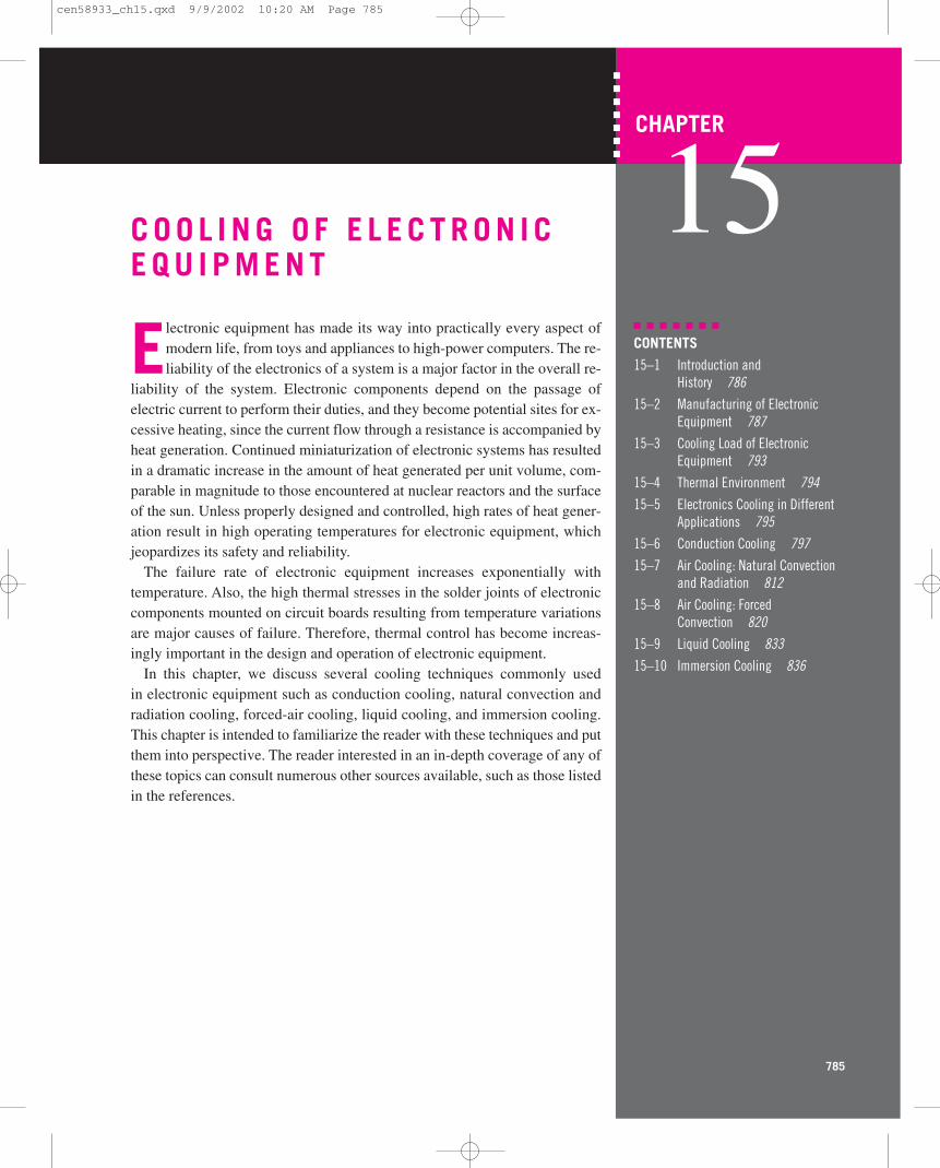
The next turning point in electronics occurred in 1959 with the introductionof the integrated circuits (IC), where several components such as diodes,transistors, resistors, and capacitors are placed in a single chip. The number ofcomponents packed in a single chip has been increasing steadily since then atan amazing rate, as shown in Figure 15–1. The continued miniaturization ofelectronic components has resulted in medium-scale integration (MSI) in the1960s with 50–1000 components per chip, large-scale integration (LSI) inthe 1970s with 1000–100,000 components per chip, and very large-scale inte-gration (VLSI) in the 1980s with 100,000–10,000,000 components per chip.Today it is not unusual to have a chip 3 cm � 3 cm in size with several mil-lion components on it.
The development of the microprocessor in the early 1970s by the IntelCorporation marked yet another beginning in the electronics industry. The ac-companying rapid development of large-capacity memory chips in this decademade it possible to introduce capable personal computers for use at work or athome at an affordable price. Electronics has made its way into practicallyeverything from watches to household appliances to automobiles. Today it isdifficult to imagine a new product that does not involve any electronic parts.
The current flow through a resistance is always accompanied by heatgeneration in the amount of I 2R, where I is the electric current and R is theresistance. When the transistor was first introduced, it was touted in the news-papers as a device that “produces no heat.” This certainly was a fair statement,considering the huge amount of heat generated by vacuum tubes. Obviously,the little heat generated in the transistor was no match to that generated in itspredecessor. But when thousands or even millions of such components arepacked in a small volume, the heat generated increases to such high levels thatits removal becomes a formidable task and a major concern for the safety andreliability of the electronic devices. The heat fluxes encountered in electronicdevices range from less than 1 W/cm2 to more than 100 W/cm2.
�
786HEAT TRANSFER
GSI
Com
pone
nts
per
chip
ULSI
VLSI
VLSI
MSI
SSI
1960 1970 1980
Year
1990 2000100
101
102
103
104
105
106
107
108
109
1010
FIGURE 15–1The increase in the number ofcomponents packed on a chip overthe years.
cen58933_ch15.qxd 9/9/2002 10:20 AM Page 786
Heat is generated in a resistive element for as long as current continues toflow through it. This creates a heat build-up and a subsequent temperaturerise at and around the component. The temperature of the component willcontinue rising until the component is destroyed unless heat is transferredaway from it. The temperature of the component will remain constant whenthe rate of heat removal from it equals the rate of heat generation.
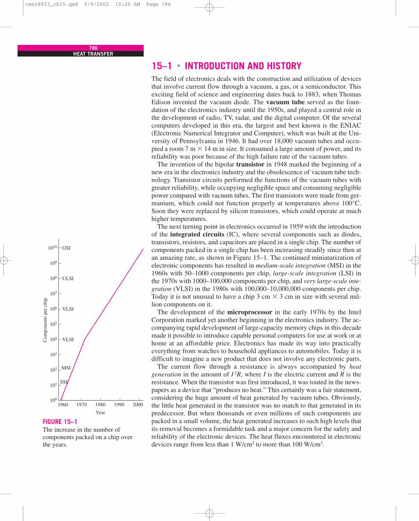
Individual electronic components have no moving parts, and thus nothing towear out with time. Therefore, they are inherently reliable, and it seems as ifthey can operate safely for many years. Indeed, this would be the case if com-ponents operated at room temperature. But electronic components are ob-served to fail under prolonged use at high temperatures. Possible causes offailure are diffusion in semiconductor materials, chemical reactions, and creepin the bonding materials, among other things. The failure rate of electronic de-vices increases almost exponentially with the operating temperature, as shownin Figure 15–2. The cooler the electronic device operates, the more reliable itis. A rule of thumb is that the failure rate of electronic components is halvedfor each 10°C reduction in their junction temperature.
15–2 MANUFACTURING OF ELECTRONICEQUIPMENT
The narrow band where two different regions of a semiconductor (such as thep-type and n-type regions) come in contact is called a junction. A transistor,for example, involves two such junctions, and a diode, which is the simplestsemiconductor device, is based on a single p-n junction. In heat transfer analy-sis, the circuitry of an electronic component through which electrons flowand thus heat is generated is also referred to as the junction. That is, junctionsare the sites of heat generation and thus the hottest spots in a component. Insilicon-based semiconductor devices, the junction temperature is limited to125°C for safe operation. However, lower junction temperatures are desirablefor extended life and lower maintenance costs. In a typical application, nu-merous electronic components, some smaller than 1 �m in size, are formedfrom a silicon wafer into a chip.
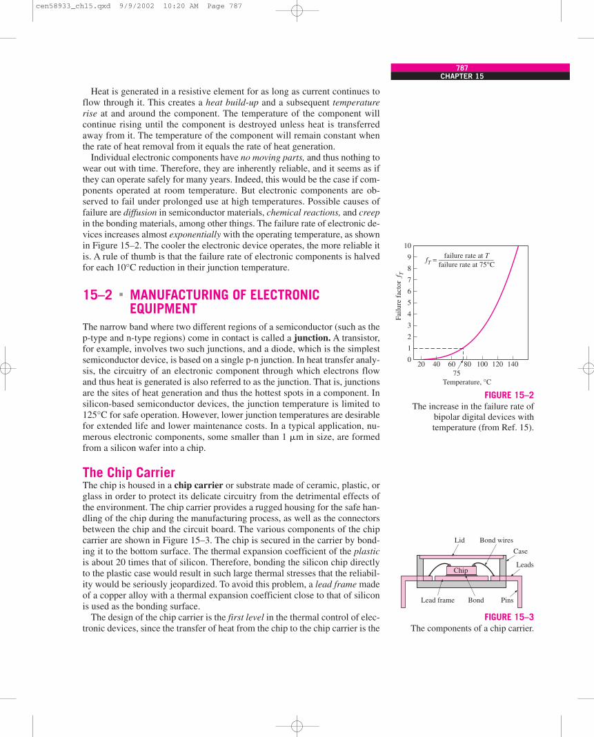
The Chip CarrierThe chip is housed in a chip carrier or substrate made of ceramic, plastic, orglass in order to protect its delicate circuitry from the detrimental effects ofthe environment. The chip carrier provides a rugged housing for the safe han-dling of the chip during the manufacturing process, as well as the connectorsbetween the chip and the circuit board. The various components of the chipcarrier are shown in Figure 15–3. The chip is secured in the carrier by bond-ing it to the bottom surface. The thermal expansion coefficient of the plasticis about 20 times that of silicon. Therefore, bonding the silicon chip directlyto the plastic case would result in such large thermal stresses that the reliabil-ity would be seriously jeopardized. To avoid this problem, a lead frame madeof a copper alloy with a thermal expansion coefficient close to that of siliconis used as the bonding surface.
The design of the chip carrier is the first level in the thermal control of elec-tronic devices, since the transfer of heat from the chip to the chip carrier is the
�
CHAPTER 15787
10
20 40 60 8075
Temperature, °C
100 120 140
9
8
7
6
Failu
re f
acto
r f T
fT = —–——————
5
4
3
2
1
0
failure rate at Tfailure rate at 75°C
FIGURE 15–2The increase in the failure rate of
bipolar digital devices withtemperature (from Ref. 15).
Case
Leads
PinsBond
Chip
Lead frame
Lid Bond wires
FIGURE 15–3The components of a chip carrier.
cen58933_ch15.qxd 9/9/2002 10:20 AM Page 787
first step in the dissipation of the heat generated on the chip. The heat gener-ated on the chip is transferred to the case of the chip carrier by a combinationof conduction, convection, and radiation. However, it is obvious from the fig-ure that the common chip carrier is designed with the electrical aspects inmind, and little consideration is given to the thermal aspects. First of all, thecavity of the chip carrier is filled with a gas, which is a poor heat conductor,and the case is often made of materials that are also poor conductors of heat.This results in a relatively large thermal resistance between the chip and thecase, called the junction-to-case resistance, and thus a large temperature dif-ference. As a result, the temperature of the chip will be much higher than thatof the case for a specified heat dissipation rate. The junction-to-case thermalresistance depends on the geometry and the size of the chip and the chip car-rier as well as the material properties of the bonding and the case. It variesconsiderably from one device to another and ranges from about 10°C/W tomore than 100°C/W.
Moisture in the cavity of the chip carrier is highly undesirable, since itcauses corrosion on the wiring. Therefore, chip carriers are made of materialsthat prevent the entry of moisture by diffusion and are hermetically sealed inorder to prevent the direct entry of moisture through cracks. Materials thatoutgas are also not permitted in the chip cavity, because such gases can alsocause corrosion. In products with strict hermeticity requirements, the more ex-pensive ceramic cases are used instead of the plastic ones.
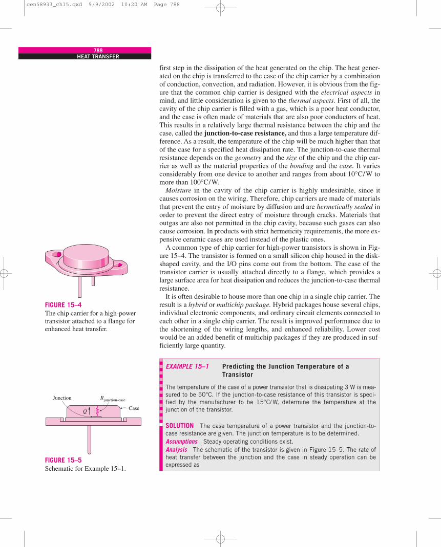
A common type of chip carrier for high-power transistors is shown in Fig-ure 15–4. The transistor is formed on a small silicon chip housed in the disk-shaped cavity, and the I/O pins come out from the bottom. The case of thetransistor carrier is usually attached directly to a flange, which provides alarge surface area for heat dissipation and reduces the junction-to-case thermalresistance.
It is often desirable to house more than one chip in a single chip carrier. Theresult is a hybrid or multichip package. Hybrid packages house several chips,individual electronic components, and ordinary circuit elements connected toeach other in a single chip carrier. The result is improved performance due tothe shortening of the wiring lengths, and enhanced reliability. Lower costwould be an added benefit of multichip packages if they are produced in suf-ficiently large quantity.
788HEAT TRANSFER
FIGURE 15–4The chip carrier for a high-powertransistor attached to a flange forenhanced heat transfer.
EXAMPLE 15–1 Predicting the Junction Temperature of aTransistor
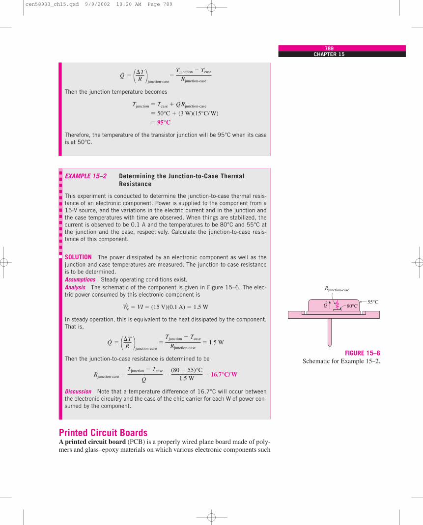
The temperature of the case of a power transistor that is dissipating 3 W is mea-sured to be 50°C. If the junction-to-case resistance of this transistor is speci-fied by the manufacturer to be 15°C/ W, determine the temperature at thejunction of the transistor.
SOLUTION The case temperature of a power transistor and the junction-to-case resistance are given. The junction temperature is to be determined.Assumptions Steady operating conditions exist.Analysis The schematic of the transistor is given in Figure 15–5. The rate ofheat transfer between the junction and the case in steady operation can beexpressed as
Junction
Case
Rjunction-case
.Q
FIGURE 15–5Schematic for Example 15–1.
cen58933_ch15.qxd 9/9/2002 10:20 AM Page 788
Printed Circuit BoardsA printed circuit board (PCB) is a properly wired plane board made of poly-mers and glass–epoxy materials on which various electronic components such
CHAPTER 15789
Q·
�junction-case
�
Then the junction temperature becomes
Tjunction � Tcase � Q·Rjunction-case
� 50°C � (3 W)(15°C/ W)
� 95°C
Therefore, the temperature of the transistor junction will be 95°C when its caseis at 50°C.
Tjunction � Tcase
Rjunction-case��TR �
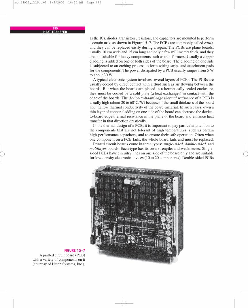
EXAMPLE 15–2 Determining the Junction-to-Case ThermalResistance
This experiment is conducted to determine the junction-to-case thermal resis-tance of an electronic component. Power is supplied to the component from a15-V source, and the variations in the electric current and in the junction andthe case temperatures with time are observed. When things are stabilized, thecurrent is observed to be 0.1 A and the temperatures to be 80°C and 55°C atthe junction and the case, respectively. Calculate the junction-to-case resis-tance of this component.
SOLUTION The power dissipated by an electronic component as well as thejunction and case temperatures are measured. The junction-to-case resistanceis to be determined.Assumptions Steady operating conditions exist.Analysis The schematic of the component is given in Figure 15–6. The elec-tric power consumed by this electronic component is
W·e � VI � (15 V)(0.1 A) � 1.5 W
In steady operation, this is equivalent to the heat dissipated by the component.That is,
Q·
� � � 1.5 W
Then the junction-to-case resistance is determined to be
Rjunction-case � � 16.7°C/ W
Discussion Note that a temperature difference of 16.7°C will occur betweenthe electronic circuitry and the case of the chip carrier for each W of power con-sumed by the component.
Tjunction � Tcase
Q· �
(80 � 55)°C1.5 W
Tjunction � Tcase
Rjunction-case��TR �
junction-case
55°C80°C
Rjunction-case
.Q
FIGURE 15–6Schematic for Example 15–2.
cen58933_ch15.qxd 9/9/2002 10:20 AM Page 789
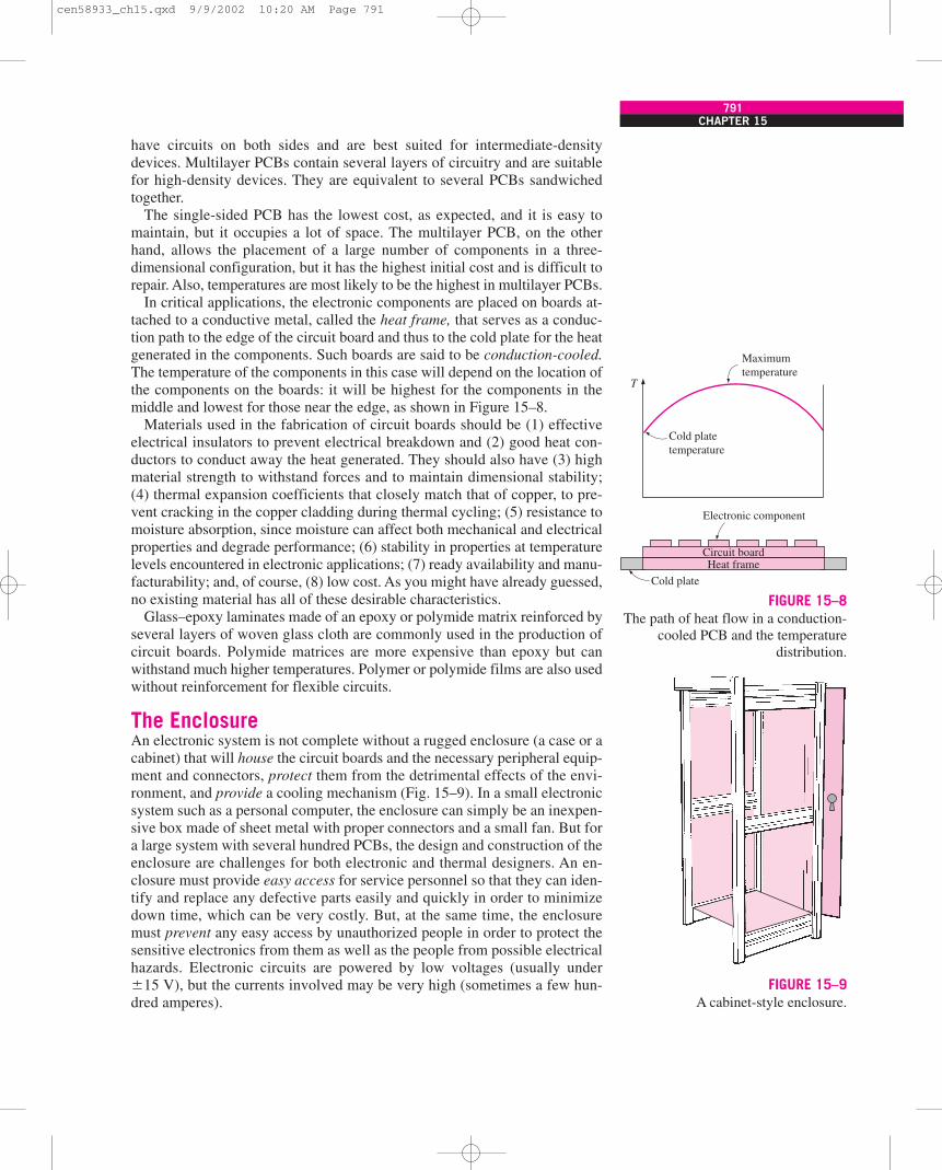
as the ICs, diodes, transistors, resistors, and capacitors are mounted to performa certain task, as shown in Figure 15–7. The PCBs are commonly called cards,and they can be replaced easily during a repair. The PCBs are plane boards,usually 10 cm wide and 15 cm long and only a few millimeters thick, and theyare not suitable for heavy components such as transformers. Usually a coppercladding is added on one or both sides of the board. The cladding on one sideis subjected to an etching process to form wiring strips and attachment padsfor the components. The power dissipated by a PCB usually ranges from 5 Wto about 30 W.
A typical electronic system involves several layers of PCBs. The PCBs areusually cooled by direct contact with a fluid such as air flowing between theboards. But when the boards are placed in a hermetically sealed enclosure,they must be cooled by a cold plate (a heat exchanger) in contact with theedge of the boards. The device-to-board edge thermal resistance of a PCB isusually high (about 20 to 60°C/W) because of the small thickness of the boardand the low thermal conductivity of the board material. In such cases, even athin layer of copper cladding on one side of the board can decrease the device-to-board edge thermal resistance in the plane of the board and enhance heattransfer in that direction drastically.
In the thermal design of a PCB, it is important to pay particular attention tothe components that are not tolerant of high temperatures, such as certainhigh-performance capacitors, and to ensure their safe operation. Often whenone component on a PCB fails, the whole board fails and must be replaced.
Printed circuit boards come in three types: single-sided, double-sided, andmultilayer boards. Each type has its own strengths and weaknesses. Single-sided PCBs have circuitry lines on one side of the board only and are suitablefor low-density electronic devices (10 to 20 components). Double-sided PCBs
790HEAT TRANSFER
FIGURE 15–7A printed circuit board (PCB)
with a variety of components on it(courtesy of Litton Systems, Inc.).
cen58933_ch15.qxd 9/9/2002 10:20 AM Page 790
have circuits on both sides and are best suited for intermediate-densitydevices. Multilayer PCBs contain several layers of circuitry and are suitablefor high-density devices. They are equivalent to several PCBs sandwichedtogether.
The single-sided PCB has the lowest cost, as expected, and it is easy tomaintain, but it occupies a lot of space. The multilayer PCB, on the otherhand, allows the placement of a large number of components in a three-dimensional configuration, but it has the highest initial cost and is difficult torepair. Also, temperatures are most likely to be the highest in multilayer PCBs.
In critical applications, the electronic components are placed on boards at-tached to a conductive metal, called the heat frame, that serves as a conduc-tion path to the edge of the circuit board and thus to the cold plate for the heatgenerated in the components. Such boards are said to be conduction-cooled.The temperature of the components in this case will depend on the location ofthe components on the boards: it will be highest for the components in themiddle and lowest for those near the edge, as shown in Figure 15–8.
Materials used in the fabrication of circuit boards should be (1) effectiveelectrical insulators to prevent electrical breakdown and (2) good heat con-ductors to conduct away the heat generated. They should also have (3) highmaterial strength to withstand forces and to maintain dimensional stability;(4) thermal expansion coefficients that closely match that of copper, to pre-vent cracking in the copper cladding during thermal cycling; (5) resistance tomoisture absorption, since moisture can affect both mechanical and electricalproperties and degrade performance; (6) stability in properties at temperaturelevels encountered in electronic applications; (7) ready availability and manu-facturability; and, of course, (8) low cost. As you might have already guessed,no existing material has all of these desirable characteristics.
Glass–epoxy laminates made of an epoxy or polymide matrix reinforced byseveral layers of woven glass cloth are commonly used in the production ofcircuit boards. Polymide matrices are more expensive than epoxy but canwithstand much higher temperatures. Polymer or polymide films are also usedwithout reinforcement for flexible circuits.
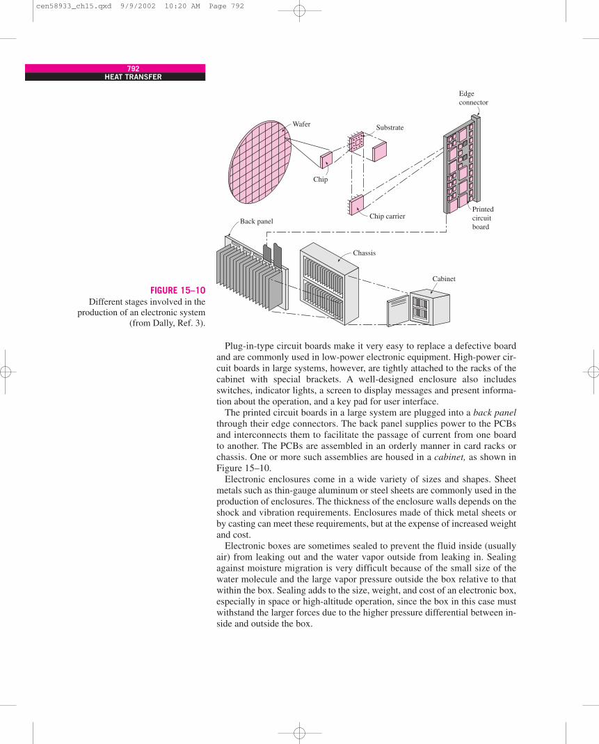
The EnclosureAn electronic system is not complete without a rugged enclosure (a case or acabinet) that will house the circuit boards and the necessary peripheral equip-ment and connectors, protect them from the detrimental effects of the envi-ronment, and provide a cooling mechanism (Fig. 15–9). In a small electronicsystem such as a personal computer, the enclosure can simply be an inexpen-sive box made of sheet metal with proper connectors and a small fan. But fora large system with several hundred PCBs, the design and construction of theenclosure are challenges for both electronic and thermal designers. An en-closure must provide easy access for service personnel so that they can iden-tify and replace any defective parts easily and quickly in order to minimizedown time, which can be very costly. But, at the same time, the enclosuremust prevent any easy access by unauthorized people in order to protect thesensitive electronics from them as well as the people from possible electricalhazards. Electronic circuits are powered by low voltages (usually under�15 V), but the currents involved may be very high (sometimes a few hun-dred amperes).
CHAPTER 15791
T
Maximumtemperature
Cold platetemperature
Cold plate
Electronic component
Circuit boardHeat frame
FIGURE 15–8The path of heat flow in a conduction-
cooled PCB and the temperaturedistribution.
FIGURE 15–9A cabinet-style enclosure.
cen58933_ch15.qxd 9/9/2002 10:20 AM Page 791
Plug-in-type circuit boards make it very easy to replace a defective boardand are commonly used in low-power electronic equipment. High-power cir-cuit boards in large systems, however, are tightly attached to the racks of thecabinet with special brackets. A well-designed enclosure also includesswitches, indicator lights, a screen to display messages and present informa-tion about the operation, and a key pad for user interface.
The printed circuit boards in a large system are plugged into a back panelthrough their edge connectors. The back panel supplies power to the PCBsand interconnects them to facilitate the passage of current from one boardto another. The PCBs are assembled in an orderly manner in card racks orchassis. One or more such assemblies are housed in a cabinet, as shown inFigure 15–10.
Electronic enclosures come in a wide variety of sizes and shapes. Sheetmetals such as thin-gauge aluminum or steel sheets are commonly used in theproduction of enclosures. The thickness of the enclosure walls depends on theshock and vibration requirements. Enclosures made of thick metal sheets orby casting can meet these requirements, but at the expense of increased weightand cost.
Electronic boxes are sometimes sealed to prevent the fluid inside (usuallyair) from leaking out and the water vapor outside from leaking in. Sealingagainst moisture migration is very difficult because of the small size of thewater molecule and the large vapor pressure outside the box relative to thatwithin the box. Sealing adds to the size, weight, and cost of an electronic box,especially in space or high-altitude operation, since the box in this case mustwithstand the larger forces due to the higher pressure differential between in-side and outside the box.
792HEAT TRANSFER
FIGURE 15–10Different stages involved in the
production of an electronic system(from Dally, Ref. 3).
Wafer
Chip
Chip carrier
Substrate
Printedcircuitboard
Edgeconnector
Cabinet
Chassis
Back panel
cen58933_ch15.qxd 9/9/2002 10:20 AM Page 792
15–3 COOLING LOAD OF ELECTRONIC EQUIPMENTThe first step in the selection and design of a cooling system is the determina-tion of the heat dissipation, which constitutes the cooling load. The easiestway to determine the power dissipation of electronic equipment is to measurethe voltage applied V and the electric current I at the entrance of the electronicdevice under full-load conditions and to substitute them into the relation
W·
e � VI � I 2R (W) (15-1)
where W·
e is the electric power consumption of the electronic device, whichconstitutes the energy input to the device.
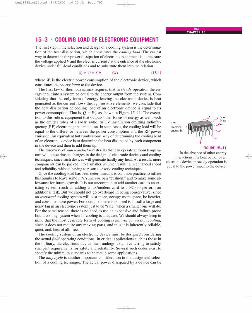
The first law of thermodynamics requires that in steady operation the en-ergy input into a system be equal to the energy output from the system. Con-sidering that the only form of energy leaving the electronic device is heatgenerated as the current flows through resistive elements, we conclude thatthe heat dissipation or cooling load of an electronic device is equal to itspower consumption. That is, Q
·� W
·e, as shown in Figure 15–11. The excep-
tion to this rule is equipment that outputs other forms of energy as well, suchas the emitter tubes of a radar, radio, or TV installation emitting radiofre-quency (RF) electromagnetic radiation. In such cases, the cooling load will beequal to the difference between the power consumption and the RF poweremission. An equivalent but cumbersome way of determining the cooling loadof an electronic device is to determine the heat dissipated by each componentin the device and then to add them up.
The discovery of superconductor materials that can operate at room tempera-ture will cause drastic changes in the design of electronic devices and coolingtechniques, since such devices will generate hardly any heat. As a result, morecomponents can be packed into a smaller volume, resulting in enhanced speedand reliability without having to resort to exotic cooling techniques.
Once the cooling load has been determined, it is common practice to inflatethis number to leave some safety margin, or a “cushion,” and to make some al-lowance for future growth. It is not uncommon to add another card to an ex-isting system (such as adding a fax/modem card to a PC) to perform anadditional task. But we should not go overboard in being conservative, sincean oversized cooling system will cost more, occupy more space, be heavier,and consume more power. For example, there is no need to install a large andnoisy fan in an electronic system just to be “safe” when a smaller one will do.For the same reason, there is no need to use an expensive and failure-proneliquid cooling system when air cooling is adequate. We should always keep inmind that the most desirable form of cooling is natural convection cooling,since it does not require any moving parts, and thus it is inherently reliable,quiet, and, best of all, free.
The cooling system of an electronic device must be designed consideringthe actual field operating conditions. In critical applications such as those inthe military, the electronic device must undergo extensive testing to satisfystringent requirements for safety and reliability. Several such codes exist tospecify the minimum standards to be met in some applications.
The duty cycle is another important consideration in the design and selec-tion of a cooling technique. The actual power dissipated by a device can be
�
CHAPTER 15793
5 WHeatout5 W
electricalenergy in
FIGURE 15–11In the absence of other energy
interactions, the heat output of anelectronic device in steady operation isequal to the power input to the device.
cen58933_ch15.qxd 9/9/2002 10:20 AM Page 793
much less than the rated power, depending on its duty cycle (the fraction oftime it is on). A 5-W power transistor, for example, will dissipate an averageof 2 W of power if it is active only 40 percent of the time. If the chip of thistransistor is 1.5 mm wide, 1.5 mm high, and 0.1 mm thick, then the heat fluxon the chip will be (2 W)/(0.15 cm)2 � 89 W/cm2.
An electronic device that is not running is in thermal equilibrium with its sur-roundings, and thus is at the temperature of the surrounding medium. When thedevice is turned on, the temperature of the components and thus the device startsrising as a result of absorbing the heat generated. The temperature of the devicestabilizes at some point when the heat generated equals the heat removed by thecooling mechanism. At this point, the device is said to have reached steady op-erating conditions. The warming-up period during which the component tem-perature rises is called the transient operation stage (Fig. 15–12).
Another thermal factor that undermines the reliability of electronic devicesis the thermal stresses caused by temperature cycling. In an experimentalstudy (see Hilbert and Kube, Ref. 10), the failure rate of electronic devicessubjected to deliberate temperature cycling of more than 20°C is observed toincrease eightfold. Shock and vibration are other common causes of failure forelectronic devices and should be considered in the design and manufacturingprocess for increased reliability.
Most electronic devices operate for long periods of time, and thus theircooling mechanism is designed for steady operation. But electronic devices insome applications never run long enough to reach steady operation. In suchcases, it may be sufficient to use a limited cooling technique, such as thermalstorage for a short period, or not to use one at all. Transient operation canalso be caused by large swings in the environmental conditions. A commoncooling technique for transient operation is to use a double-wall constructionfor the enclosure of the electronic equipment, with the space between thewalls filled with a wax with a suitable melting temperature. As the wax melts,it absorbs a large amount of heat and thus delays overheating of the electroniccomponents considerably. During off periods, the wax solidifies by rejectingheat to the environment.
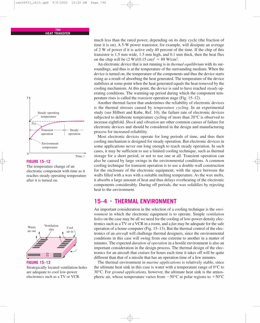
15–4 THERMAL ENVIRONMENTAn important consideration in the selection of a cooling technique is the envi-ronment in which the electronic equipment is to operate. Simple ventilationholes on the case may be all we need for the cooling of low-power-density elec-tronics such as a TV or a VCR in a room, and a fan may be adequate for the safeoperation of a home computer (Fig. 15–13). But the thermal control of the elec-tronics of an aircraft will challenge thermal designers, since the environmentalconditions in this case will swing from one extreme to another in a matter ofminutes. The expected duration of operation in a hostile environment is also animportant consideration in the design process. The thermal design of the elec-tronics for an aircraft that cruises for hours each time it takes off will be quitedifferent than that of a missile that has an operation time of a few minutes.
The thermal environment in marine applications is relatively stable, sincethe ultimate heat sink in this case is water with a temperature range of 0°C to30°C. For ground applications, however, the ultimate heat sink is the atmos-pheric air, whose temperature varies from �50°C at polar regions to �50°C
�
794HEAT TRANSFER
Transientoperation
Environmenttemperature
Steady operatingtemperature
Steadyoperation
T
0Time, t
T(t)
FIGURE 15–12The temperature change of anelectronic component with time as itreaches steady operating temperatureafter it is turned on.
Warmair out
Ventilationslits Cool
air in
FIGURE 15–13Strategically located ventilation holesare adequate to cool low-powerelectronics such as a TV or VCR.
cen58933_ch15.qxd 9/9/2002 10:20 AM Page 794
in desert climates, and whose pressure ranges from about 70 kPa (0.7 atm) at3000 m elevation to 107 kPa (1.08 atm) at 500 m below sea level. The com-bined convection and radiation heat transfer coefficient can range from10 W/m2 · °C in calm weather to 80 W/m2 · °C in 100 km/h (62 mph) winds.Also, the surfaces of the devices facing the sun directly can be subjected tosolar radiation heat flux of 1000 W/m2 on a clear day.
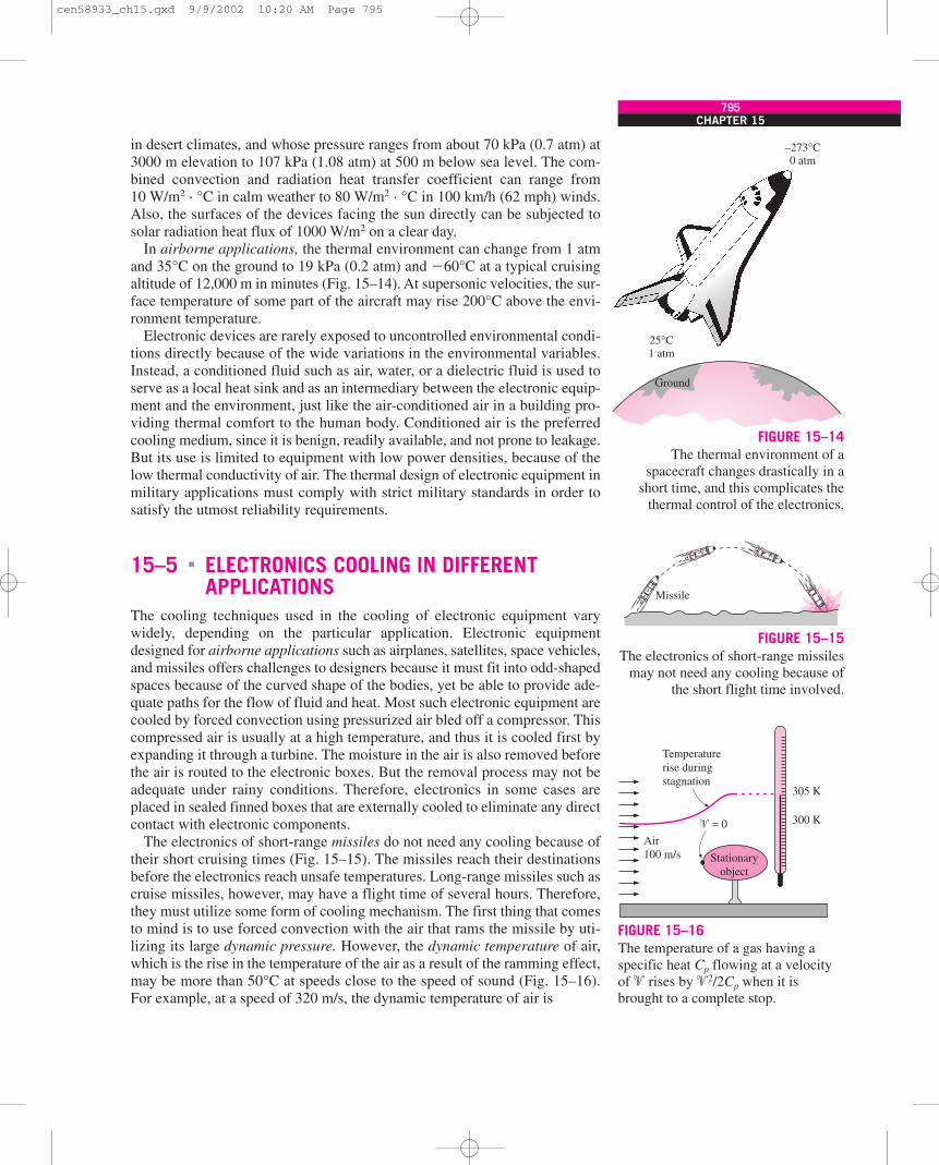
In airborne applications, the thermal environment can change from 1 atmand 35°C on the ground to 19 kPa (0.2 atm) and �60°C at a typical cruisingaltitude of 12,000 m in minutes (Fig. 15–14). At supersonic velocities, the sur-face temperature of some part of the aircraft may rise 200°C above the envi-ronment temperature.
Electronic devices are rarely exposed to uncontrolled environmental condi-tions directly because of the wide variations in the environmental variables.Instead, a conditioned fluid such as air, water, or a dielectric fluid is used toserve as a local heat sink and as an intermediary between the electronic equip-ment and the environment, just like the air-conditioned air in a building pro-viding thermal comfort to the human body. Conditioned air is the preferredcooling medium, since it is benign, readily available, and not prone to leakage.But its use is limited to equipment with low power densities, because of thelow thermal conductivity of air. The thermal design of electronic equipment inmilitary applications must comply with strict military standards in order tosatisfy the utmost reliability requirements.
15–5 ELECTRONICS COOLING IN DIFFERENTAPPLICATIONS
The cooling techniques used in the cooling of electronic equipment varywidely, depending on the particular application. Electronic equipmentdesigned for airborne applications such as airplanes, satellites, space vehicles,and missiles offers challenges to designers because it must fit into odd-shapedspaces because of the curved shape of the bodies, yet be able to provide ade-quate paths for the flow of fluid and heat. Most such electronic equipment arecooled by forced convection using pressurized air bled off a compressor. Thiscompressed air is usually at a high temperature, and thus it is cooled first byexpanding it through a turbine. The moisture in the air is also removed beforethe air is routed to the electronic boxes. But the removal process may not beadequate under rainy conditions. Therefore, electronics in some cases areplaced in sealed finned boxes that are externally cooled to eliminate any directcontact with electronic components.
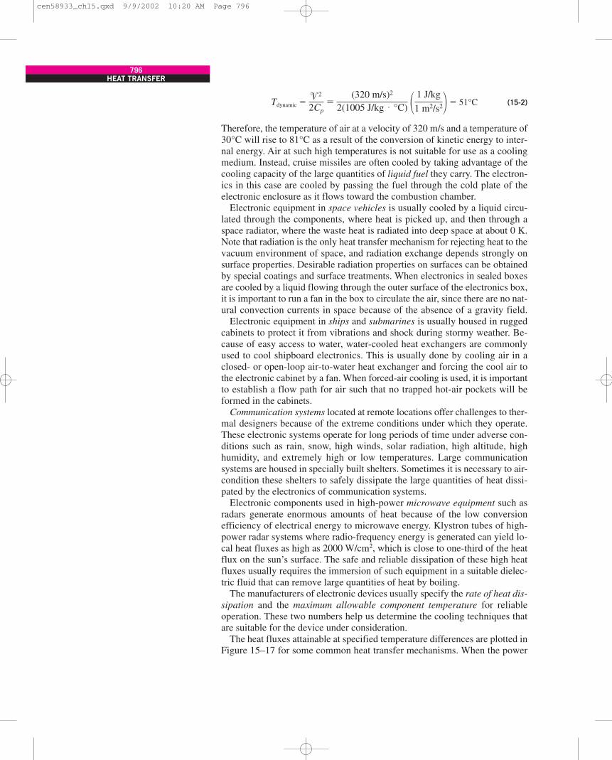
The electronics of short-range missiles do not need any cooling because oftheir short cruising times (Fig. 15–15). The missiles reach their destinationsbefore the electronics reach unsafe temperatures. Long-range missiles such ascruise missiles, however, may have a flight time of several hours. Therefore,they must utilize some form of cooling mechanism. The first thing that comesto mind is to use forced convection with the air that rams the missile by uti-lizing its large dynamic pressure. However, the dynamic temperature of air,which is the rise in the temperature of the air as a result of the ramming effect,may be more than 50°C at speeds close to the speed of sound (Fig. 15–16).For example, at a speed of 320 m/s, the dynamic temperature of air is
�
CHAPTER 15795
25°C1 atm
–273°C0 atm
Ground
FIGURE 15–14The thermal environment of a
spacecraft changes drastically in ashort time, and this complicates the
thermal control of the electronics.
Missile
FIGURE 15–15The electronics of short-range missiles
may not need any cooling because ofthe short flight time involved.
Temperaturerise duringstagnation
Air100 m/s
305 K
300 K� = 0
Stationaryobject
FIGURE 15–16The temperature of a gas having aspecific heat Cp flowing at a velocityof � rises by �2/2Cp when it isbrought to a complete stop.
cen58933_ch15.qxd 9/9/2002 10:20 AM Page 795
Tdynamic � � 51°C (15-2)
Therefore, the temperature of air at a velocity of 320 m/s and a temperature of30°C will rise to 81°C as a result of the conversion of kinetic energy to inter-nal energy. Air at such high temperatures is not suitable for use as a coolingmedium. Instead, cruise missiles are often cooled by taking advantage of thecooling capacity of the large quantities of liquid fuel they carry. The electron-ics in this case are cooled by passing the fuel through the cold plate of theelectronic enclosure as it flows toward the combustion chamber.
Electronic equipment in space vehicles is usually cooled by a liquid circu-lated through the components, where heat is picked up, and then through aspace radiator, where the waste heat is radiated into deep space at about 0 K.Note that radiation is the only heat transfer mechanism for rejecting heat to thevacuum environment of space, and radiation exchange depends strongly onsurface properties. Desirable radiation properties on surfaces can be obtainedby special coatings and surface treatments. When electronics in sealed boxesare cooled by a liquid flowing through the outer surface of the electronics box,it is important to run a fan in the box to circulate the air, since there are no nat-ural convection currents in space because of the absence of a gravity field.
Electronic equipment in ships and submarines is usually housed in ruggedcabinets to protect it from vibrations and shock during stormy weather. Be-cause of easy access to water, water-cooled heat exchangers are commonlyused to cool shipboard electronics. This is usually done by cooling air in aclosed- or open-loop air-to-water heat exchanger and forcing the cool air tothe electronic cabinet by a fan. When forced-air cooling is used, it is importantto establish a flow path for air such that no trapped hot-air pockets will beformed in the cabinets.
Communication systems located at remote locations offer challenges to ther-mal designers because of the extreme conditions under which they operate.These electronic systems operate for long periods of time under adverse con-ditions such as rain, snow, high winds, solar radiation, high altitude, highhumidity, and extremely high or low temperatures. Large communicationsystems are housed in specially built shelters. Sometimes it is necessary to air-condition these shelters to safely dissipate the large quantities of heat dissi-pated by the electronics of communication systems.
Electronic components used in high-power microwave equipment such asradars generate enormous amounts of heat because of the low conversionefficiency of electrical energy to microwave energy. Klystron tubes of high-power radar systems where radio-frequency energy is generated can yield lo-cal heat fluxes as high as 2000 W/cm2, which is close to one-third of the heatflux on the sun’s surface. The safe and reliable dissipation of these high heatfluxes usually requires the immersion of such equipment in a suitable dielec-tric fluid that can remove large quantities of heat by boiling.
The manufacturers of electronic devices usually specify the rate of heat dis-sipation and the maximum allowable component temperature for reliableoperation. These two numbers help us determine the cooling techniques thatare suitable for the device under consideration.
The heat fluxes attainable at specified temperature differences are plotted inFigure 15–17 for some common heat transfer mechanisms. When the power
�2
2Cp�
(320 m/s)2
2(1005 J/kg · °C) � 1 J/kg
1 m2/s2�
796HEAT TRANSFER
cen58933_ch15.qxd 9/9/2002 10:20 AM Page 796
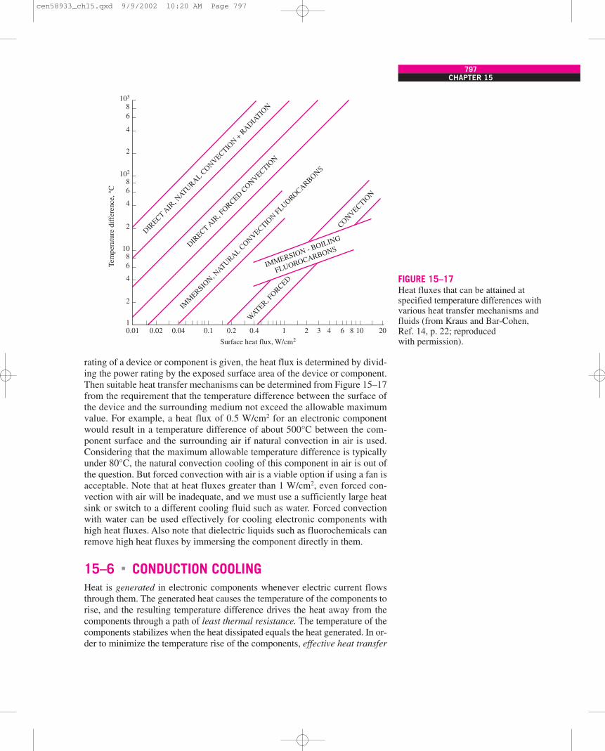
rating of a device or component is given, the heat flux is determined by divid-ing the power rating by the exposed surface area of the device or component.Then suitable heat transfer mechanisms can be determined from Figure 15–17from the requirement that the temperature difference between the surface ofthe device and the surrounding medium not exceed the allowable maximumvalue. For example, a heat flux of 0.5 W/cm2 for an electronic componentwould result in a temperature difference of about 500°C between the com-ponent surface and the surrounding air if natural convection in air is used.Considering that the maximum allowable temperature difference is typicallyunder 80°C, the natural convection cooling of this component in air is out ofthe question. But forced convection with air is a viable option if using a fan isacceptable. Note that at heat fluxes greater than 1 W/cm2, even forced con-vection with air will be inadequate, and we must use a sufficiently large heatsink or switch to a different cooling fluid such as water. Forced convectionwith water can be used effectively for cooling electronic components withhigh heat fluxes. Also note that dielectric liquids such as fluorochemicals canremove high heat fluxes by immersing the component directly in them.
15–6 CONDUCTION COOLINGHeat is generated in electronic components whenever electric current flowsthrough them. The generated heat causes the temperature of the components torise, and the resulting temperature difference drives the heat away from thecomponents through a path of least thermal resistance. The temperature of thecomponents stabilizes when the heat dissipated equals the heat generated. In or-der to minimize the temperature rise of the components, effective heat transfer
�
CHAPTER 15797
FIGURE 15–17Heat fluxes that can be attained atspecified temperature differences withvarious heat transfer mechanisms andfluids (from Kraus and Bar-Cohen,Ref. 14, p. 22; reproducedwith permission).
WATER, F
ORCED
CONVECTION
DIRECT
AIR, N
ATURALCONVECTIO
N+
RADIATIO
N
DIRECT
AIR, F
ORCEDCONVECTIO
N
IMM
ERSION, N
ATURALCONVECTIO
NFLUOROCARBONS
IMMERSION - BOILING
FLUOROCARBONS
103
8
86
4
2
6
Surface heat flux, W/cm2
Tem
pera
ture
dif
fere
nce,
°C
4
2
102
1086
4
2
10.01 0.02 0.04 0.1 0.2 0.4 1 2 3 4 6 8 10 20
cen58933_ch15.qxd 9/9/2002 10:20 AM Page 797
paths must be established between the components and the ultimate heat sink,which is usually the atmospheric air.
The selection of a cooling mechanism for electronic equipment depends onthe magnitude of the heat generated, reliability requirements, environmentalconditions, and cost. For low-cost electronic equipment, inexpensive coolingmechanisms such as natural or forced convection with air as the coolingmedium are commonly used. For high-cost, high-performance electronicequipment, however, it is often necessary to resort to expensive and compli-cated cooling techniques.
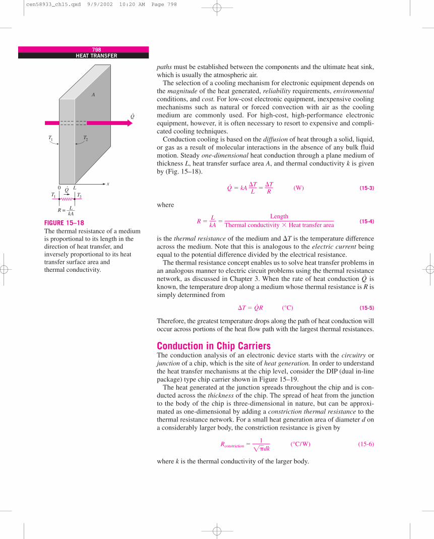
Conduction cooling is based on the diffusion of heat through a solid, liquid,or gas as a result of molecular interactions in the absence of any bulk fluidmotion. Steady one-dimensional heat conduction through a plane medium ofthickness L, heat transfer surface area A, and thermal conductivity k is givenby (Fig. 15–18).
Q·
� kA (W) (15-3)
where
R � (15-4)
is the thermal resistance of the medium and �T is the temperature differenceacross the medium. Note that this is analogous to the electric current beingequal to the potential difference divided by the electrical resistance.
The thermal resistance concept enables us to solve heat transfer problems inan analogous manner to electric circuit problems using the thermal resistancenetwork, as discussed in Chapter 3. When the rate of heat conduction Q
·is
known, the temperature drop along a medium whose thermal resistance is R issimply determined from
�T � Q·R (°C) (15-5)
Therefore, the greatest temperature drops along the path of heat conduction willoccur across portions of the heat flow path with the largest thermal resistances.
Conduction in Chip CarriersThe conduction analysis of an electronic device starts with the circuitry orjunction of a chip, which is the site of heat generation. In order to understandthe heat transfer mechanisms at the chip level, consider the DIP (dual in-linepackage) type chip carrier shown in Figure 15–19.
The heat generated at the junction spreads throughout the chip and is con-ducted across the thickness of the chip. The spread of heat from the junctionto the body of the chip is three-dimensional in nature, but can be approxi-mated as one-dimensional by adding a constriction thermal resistance to thethermal resistance network. For a small heat generation area of diameter d ona considerably larger body, the constriction resistance is given by
Rconstriction � (°C/W) (15-6)
where k is the thermal conductivity of the larger body.
1
�dk
LkA
�Length
Thermal conductivity � Heat transfer area
�TL
��TR
798HEAT TRANSFER
xL0
.Q
A
R = —–LkA
T1
T1 T2
T2
Q.
FIGURE 15–18The thermal resistance of a mediumis proportional to its length in thedirection of heat transfer, andinversely proportional to its heattransfer surface area andthermal conductivity.
cen58933_ch15.qxd 9/9/2002 10:20 AM Page 798
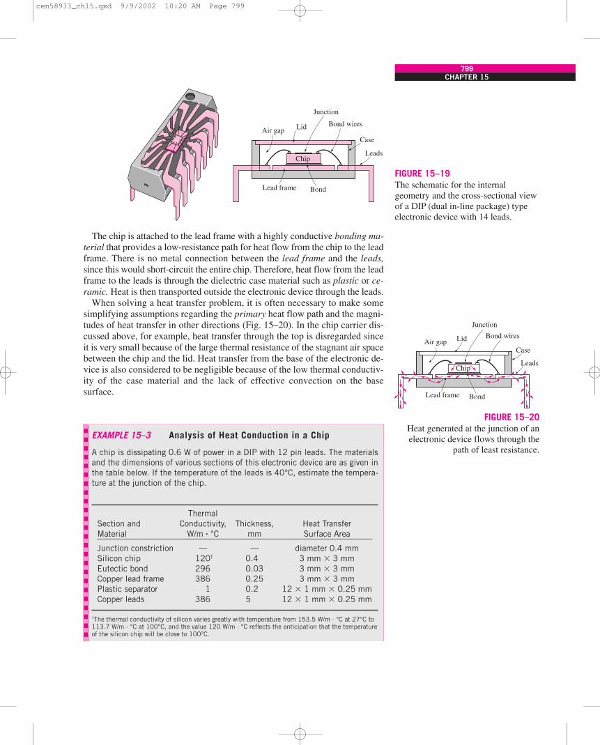
The chip is attached to the lead frame with a highly conductive bonding ma-terial that provides a low-resistance path for heat flow from the chip to the leadframe. There is no metal connection between the lead frame and the leads,since this would short-circuit the entire chip. Therefore, heat flow from the leadframe to the leads is through the dielectric case material such as plastic or ce-ramic. Heat is then transported outside the electronic device through the leads.
When solving a heat transfer problem, it is often necessary to make somesimplifying assumptions regarding the primary heat flow path and the magni-tudes of heat transfer in other directions (Fig. 15–20). In the chip carrier dis-cussed above, for example, heat transfer through the top is disregarded sinceit is very small because of the large thermal resistance of the stagnant air spacebetween the chip and the lid. Heat transfer from the base of the electronic de-vice is also considered to be negligible because of the low thermal conductiv-ity of the case material and the lack of effective convection on the basesurface.
CHAPTER 15799
FIGURE 15–19The schematic for the internalgeometry and the cross-sectional viewof a DIP (dual in-line package) typeelectronic device with 14 leads.
Case
Leads
Bond
Chip
Lead frame
LidAir gapBond wires
Junction
Case
Leads
Bond
Chip
Lead frame
LidAir gapBond wires
Junction
FIGURE 15–20Heat generated at the junction of anelectronic device flows through the
path of least resistance.
EXAMPLE 15–3 Analysis of Heat Conduction in a Chip
A chip is dissipating 0.6 W of power in a DIP with 12 pin leads. The materialsand the dimensions of various sections of this electronic device are as given inthe table below. If the temperature of the leads is 40°C, estimate the tempera-ture at the junction of the chip.
Thermal Section and Conductivity, Thickness, Heat Transfer Material W/m · °C mm Surface Area
Junction constriction — — diameter 0.4 mmSilicon chip 120† 0.4 3 mm � 3 mmEutectic bond 296 0.03 3 mm � 3 mmCopper lead frame 386 0.25 3 mm � 3 mmPlastic separator 1 0.2 12 � 1 mm � 0.25 mmCopper leads 386 5 12 � 1 mm � 0.25 mm
†The thermal conductivity of silicon varies greatly with temperature from 153.5 W/m · °C at 27°C to113.7 W/m · °C at 100°C, and the value 120 W/m · °C reflects the anticipation that the temperatureof the silicon chip will be close to 100°C.
cen58933_ch15.qxd 9/9/2002 10:20 AM Page 799
800HEAT TRANSFER
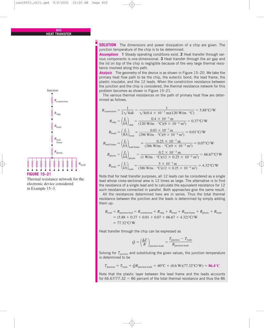
SOLUTION The dimensions and power dissipation of a chip are given. Thejunction temperature of the chip is to be determined.Assumptions 1 Steady operating conditions exist. 2 Heat transfer through var-ious components is one-dimensional. 3 Heat transfer through the air gap andthe lid on top of the chip is negligible because of the very large thermal resis-tance involved along this path.Analysis The geometry of the device is as shown in Figure 15–20. We take theprimary heat flow path to be the chip, the eutectic bond, the lead frame, theplastic insulator, and the 12 leads. When the constriction resistance betweenthe junction and the chip is considered, the thermal resistance network for thisproblem becomes as shown in Figure 15–21.
The various thermal resistances on the path of primary heat flow are deter-mined as follows.
Rconstriction � � 5.88°C/ W
Rchip � � 0.37°C/ W
Rbond � � 0.01°C/ W
Rlead frame � � 0.07°C/ W
Rplastic � � 66.67°C/ W
Rleads � � 4.32°C/ W
Note that for heat transfer purposes, all 12 leads can be considered as a singlelead whose cross-sectional area is 12 times as large. The alternative is to findthe resistance of a single lead and to calculate the equivalent resistance for 12such resistances connected in parallel. Both approaches give the same result.
All the resistances determined here are in series. Thus the total thermalresistance between the junction and the leads is determined by simply addingthem up:
Rtotal � Rjunction-lead � Rconstriction � Rchip � Rbond � Rlead frame � Rplastic � Rleads
� (5.88 � 0.37 � 0.01 � 0.07 � 66.67 � 4.32)°C/ W
� 77.32°C/ W
Heat transfer through the chip can be expressed as
Q·
�
Solving for Tjunction and substituting the given values, the junction temperatureis determined to be
Tjunction � Tleads � Q·Rjunction-leads � 40°C � (0.6 W)(77.32°C/ W) � 86.4°C
Note that the plastic layer between the lead frame and the leads accountsfor 66.67/77.32 � 86 percent of the total thermal resistance and thus the 86
��TR �
junction-leads�
Tjunction � Tleads
Rjunction-leads
� LkA�leads
�5 � 10�3 m
(386 W/m · °C)(12 � 0.25 � 10�6 m2)
� LkA�plastic
�0.2 � 10�3 m
(1 W/m · °C)(12 � 0.25 � 10�6 m2)
� LkA�lead frame
� 0.25 � 10�3 m(386 W/m · °C)(9 � 10�6 m2)
� LKA�bond
�0.03 � 10�3 m
(296 W/m · °C)(9 � 10�6 m2)
� LkA�chip
�0.4 � 10�3 m
(120 W/m · °C)(9 � 10�6 m2)
12�dk
�1
�(0.4 � 10�3 m)(120 W/m · °C)
Rconstriction
Rchip
Rbond
Rplastic
Rleads
Rlead frame
Junction
FIGURE 15–21Thermal resistance network for theelectronic device consideredin Example 15–3.
cen58933_ch15.qxd 9/9/2002 10:20 AM Page 800
The analytical determination of the junction-to-case thermal resistance ofan electronic device can be rather complicated and can involve considerableuncertainty, as already shown. Therefore, the manufacturers of electronic de-vices usually determine this value experimentally and list it as part of theirproduct description. When the thermal resistance is known, the temperaturedifference between the junction and the outer surface of the device can be de-termined from
�Tjunction-case � Tjunction � Tcase � Q·Rjunction-case (°C) (15-7)
where Q·
is the power consumed by the device.The determination of the actual junction temperature depends on the
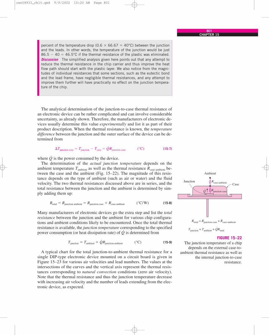
ambient temperature Tambient as well as the thermal resistance Rcase-ambient be-tween the case and the ambient (Fig. 15–22). The magnitude of this resis-tance depends on the type of ambient (such as air or water) and the fluidvelocity. The two thermal resistances discussed above are in series, and thetotal resistance between the junction and the ambient is determined by sim-ply adding them up:
Rtotal � Rjunction-ambient � Rjunction-case � Rcase-ambient (°C/W) (15-8)
Many manufacturers of electronic devices go the extra step and list the totalresistance between the junction and the ambient for various chip configura-tions and ambient conditions likely to be encountered. Once the total thermalresistance is available, the junction temperature corresponding to the specifiedpower consumption (or heat dissipation rate) of Q
·is determined from
Tjunction � Tambient � Q·Rjunction-ambient (°C) (15-9)
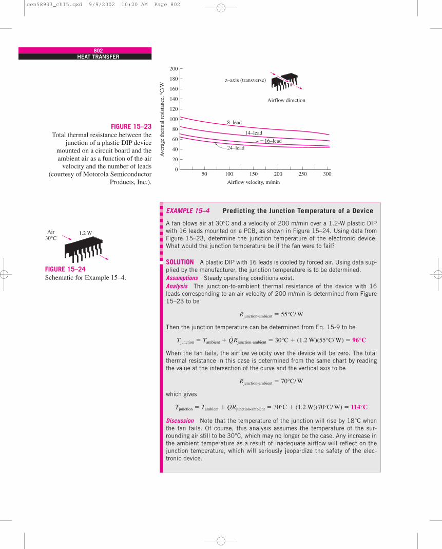
A typical chart for the total junction-to-ambient thermal resistance for asingle DIP-type electronic device mounted on a circuit board is given inFigure 15–23 for various air velocities and lead numbers. The values at theintersections of the curves and the vertical axis represent the thermal resis-tances corresponding to natural convection conditions (zero air velocity).Note that the thermal resistance and thus the junction temperature decreasewith increasing air velocity and the number of leads extending from the elec-tronic device, as expected.
CHAPTER 15801
percent of the temperature drop (0.6 � 66.67 � 40°C) between the junctionand the leads. In other words, the temperature of the junction would be just86.5 � 40 � 46.5°C if the thermal resistance of the plastic was eliminated.Discussion The simplified analysis given here points out that any attempt toreduce the thermal resistance in the chip carrier and thus improve the heatflow path should start with the plastic layer. We also notice from the magni-tudes of individual resistances that some sections, such as the eutectic bondand the lead frame, have negligible thermal resistances, and any attempt toimprove them further will have practically no effect on the junction tempera-ture of the chip.
Rcase-ambient
Rtotal = Rjunction-case + Rcase-ambient
Tjunction = Tambient + QRtotal
Rjunction-case
CaseJunction
Ambient
.
.
Q
FIGURE 15–22The junction temperature of a chip
depends on the external case-to-ambient thermal resistance as well as
the internal junction-to-caseresistance.
cen58933_ch15.qxd 9/9/2002 10:20 AM Page 801
802HEAT TRANSFER
FIGURE 15–23Total thermal resistance between the
junction of a plastic DIP devicemounted on a circuit board and theambient air as a function of the air
velocity and the number of leads(courtesy of Motorola Semiconductor
Products, Inc.).
200
180
160
140
120
100
80
60
40
20
050 100
Airflow velocity, m/min
150 200 250 300
8–lead
24–lead
14–lead
16–lead
z–axis (transverse)
Airflow direction
Ave
rage
ther
mal
res
ista
nce,
°C/ W
EXAMPLE 15–4 Predicting the Junction Temperature of a Device
A fan blows air at 30°C and a velocity of 200 m/min over a 1.2-W plastic DIPwith 16 leads mounted on a PCB, as shown in Figure 15–24. Using data fromFigure 15–23, determine the junction temperature of the electronic device.What would the junction temperature be if the fan were to fail?
SOLUTION A plastic DIP with 16 leads is cooled by forced air. Using data sup-plied by the manufacturer, the junction temperature is to be determined.Assumptions Steady operating conditions exist.Analysis The junction-to-ambient thermal resistance of the device with 16leads corresponding to an air velocity of 200 m/min is determined from Figure15–23 to be
Rjunction-ambient � 55°C/ W
Then the junction temperature can be determined from Eq. 15-9 to be
Tjunction � Tambient � Q·Rjunction-ambient � 30°C � (1.2 W)(55°C/ W) � 96°C
When the fan fails, the airflow velocity over the device will be zero. The totalthermal resistance in this case is determined from the same chart by readingthe value at the intersection of the curve and the vertical axis to be
Rjunction-ambient � 70°C/ W
which gives
Tjunction � Tambient � Q·Rjunction-ambient � 30°C � (1.2 W)(70°C/ W) � 114°C
Discussion Note that the temperature of the junction will rise by 18°C whenthe fan fails. Of course, this analysis assumes the temperature of the sur-rounding air still to be 30°C, which may no longer be the case. Any increase inthe ambient temperature as a result of inadequate airflow will reflect on thejunction temperature, which will seriously jeopardize the safety of the elec-tronic device.
Air30°C
1.2 W
FIGURE 15–24Schematic for Example 15–4.
cen58933_ch15.qxd 9/9/2002 10:20 AM Page 802
Conduction in Printed Circuit BoardsHeat-generating electronic devices are commonly mounted on thin rectangu-lar boards, usually 10 cm � 15 cm in size, made of electrically insulating ma-terials such as glass–epoxy laminates, which are also poor conductors of heat.The resulting printed circuit boards are usually cooled by blowing air or pass-ing a dielectric liquid through them. In such cases, the components on thePCBs are cooled directly, and we are not concerned about heat conductionalong the PCBs. But in some critical applications such as those encountered inthe military, the PCBs are contained in sealed enclosures, and the boards pro-vide the only effective heat path between the components and the heat sink at-tached to the sealed enclosure. In such cases, heat transfer from the side facesof the PCBs is negligible, and the heat generated in the components must beconducted along the PCB toward its edges, which are clamped to cold platesfor removing the heat externally.
Heat transfer along a PCB is complicated in nature because of the multidi-mensional effects and nonuniform heat generation on the surfaces. We canstill obtain sufficiently accurate results by using the thermal resistance net-work in one or more dimensions.
Copper or aluminum cladding, heat frames, or cores are commonly used toenhance heat conduction along the PCBs. The thickness of the coppercladding on the PCB is usually expressed in terms of ounces of copper, whichis the thickness of 1-ft2 copper sheet made of one ounce of copper. An ounceof copper is equivalent to 0.03556-mm (1.4-mil) thickness of a copper layer.
When analyzing heat conduction along a PCB with copper (or aluminum)cladding on one or both sides, often the question arises whether heat transferalong the epoxy laminate can be ignored relative to that along the copperlayer, since the thermal conductivity of copper is about 1500 times that ofepoxy. The answer depends on the relative cross-sectional areas of each layer,since heat conduction is proportional to the cross-sectional area as well as thethermal conductivity.
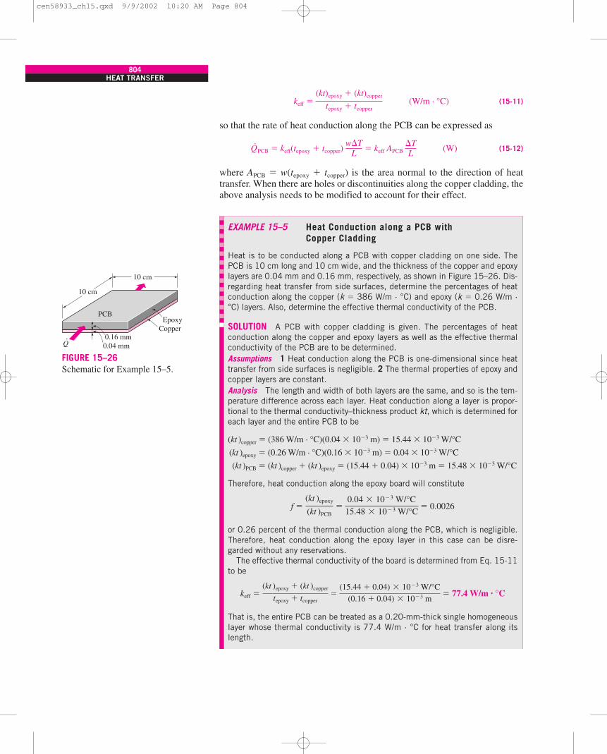
Consider a copper-cladded PCB of width w and length L, across which thetemperature difference is �T, as shown in Figure 15–25. Assuming heat con-duction is along the length L only and heat conduction in other dimensions isnegligible, the rate of heat conduction along this PCB is the sum of the heatconduction along the epoxy board and the copper layer and is expressed as
Q·
PCB � Q·
epoxy � Q·
copper �
� [(kA)epoxy � (kA)copper] (15-10)
� [(kt)epoxy � (kt)copper]
where t denotes the thickness. Therefore, the relative magnitudes of heat con-duction along the two layers depend on the relative magnitudes of the thermalconductivity–thickness product kt of the layer. Therefore, if the kt product ofthe copper is 100 times that of epoxy, then neglecting heat conduction alongthe epoxy board will involve an error of just 1 percent, which is negligible.
We can also define an effective thermal conductivity for metal-claddedPCBs as
w�TL
�TL
�kA �TL �epoxy
� �kA �TL �copper
CHAPTER 15803
tcopper
tepoxy
tPCB = tepoxy + tcopper
Epoxy
CopperPCB
L
w
.Q
FIGURE 15–25Schematic of a copper-cladded epoxy
board and heat conduction along it.
cen58933_ch15.qxd 9/9/2002 10:20 AM Page 803
keff � (W/m · °C) (15-11)
so that the rate of heat conduction along the PCB can be expressed as
Q·
PCB � keff(tepoxy � tcopper) � keff APCB (W) (15-12)
where APCB � w(tepoxy � tcopper) is the area normal to the direction of heattransfer. When there are holes or discontinuities along the copper cladding, theabove analysis needs to be modified to account for their effect.
�TL
w�TL
(kt)epoxy � (kt)copper
tepoxy � tcopper
804HEAT TRANSFER
EXAMPLE 15–5 Heat Conduction along a PCB withCopper Cladding
Heat is to be conducted along a PCB with copper cladding on one side. ThePCB is 10 cm long and 10 cm wide, and the thickness of the copper and epoxylayers are 0.04 mm and 0.16 mm, respectively, as shown in Figure 15–26. Dis-regarding heat transfer from side surfaces, determine the percentages of heatconduction along the copper (k � 386 W/m · °C) and epoxy (k � 0.26 W/m ·°C) layers. Also, determine the effective thermal conductivity of the PCB.
SOLUTION A PCB with copper cladding is given. The percentages of heatconduction along the copper and epoxy layers as well as the effective thermalconductivity of the PCB are to be determined.Assumptions 1 Heat conduction along the PCB is one-dimensional since heattransfer from side surfaces is negligible. 2 The thermal properties of epoxy andcopper layers are constant.Analysis The length and width of both layers are the same, and so is the tem-perature difference across each layer. Heat conduction along a layer is propor-tional to the thermal conductivity–thickness product kt, which is determined foreach layer and the entire PCB to be
(kt )copper � (386 W/m · °C)(0.04 � 10�3 m) � 15.44 � 10�3 W/°C
(kt )epoxy � (0.26 W/m · °C)(0.16 � 10�3 m) � 0.04 � 10�3 W/°C
(kt )PCB � (kt )copper � (kt )epoxy � (15.44 � 0.04) � 10�3 m � 15.48 � 10�3 W/°C
Therefore, heat conduction along the epoxy board will constitute
f � � 0.0026
or 0.26 percent of the thermal conduction along the PCB, which is negligible.Therefore, heat conduction along the epoxy layer in this case can be disre-garded without any reservations.
The effective thermal conductivity of the board is determined from Eq. 15-11to be
keff � � 77.4 W/m · °C
That is, the entire PCB can be treated as a 0.20-mm-thick single homogeneouslayer whose thermal conductivity is 77.4 W/m · °C for heat transfer along itslength.
(kt )epoxy � (kt )copper
tepoxy � tcopper�
(15.44 � 0.04) � 10�3 W/°C(0.16 � 0.04) � 10�3 m
(kt )epoxy
(kt )PCB�
0.04 � 10�3 W/°C15.48 � 10�3 W/°C
EpoxyCopper
PCB
.Q
10 cm
10 cm
0.16 mm0.04 mm
FIGURE 15–26Schematic for Example 15–5.
cen58933_ch15.qxd 9/9/2002 10:20 AM Page 804
Heat FramesIn applications where direct cooling of circuit boards by passing air or a di-electric liquid over the electronic components is not allowed, and the junctiontemperatures are to be maintained relatively low to meet strict safety require-ments, a thick heat frame is used instead of a thin layer of copper cladding.This is especially the case for multilayer PCBs that are packed with high-power output chips.
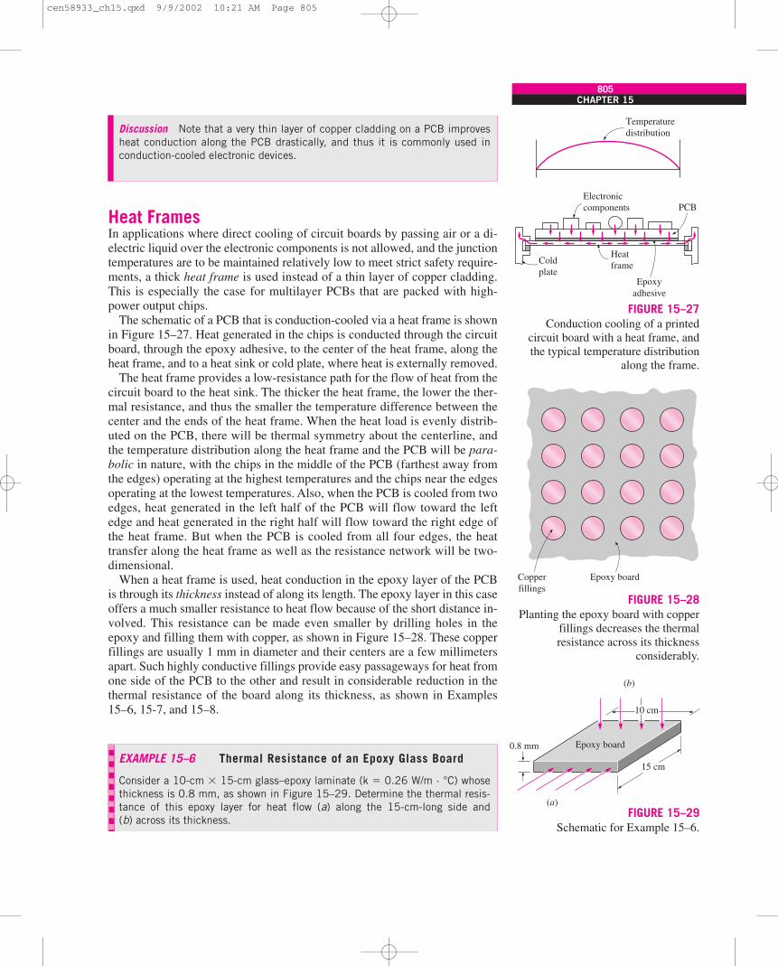
The schematic of a PCB that is conduction-cooled via a heat frame is shownin Figure 15–27. Heat generated in the chips is conducted through the circuitboard, through the epoxy adhesive, to the center of the heat frame, along theheat frame, and to a heat sink or cold plate, where heat is externally removed.
The heat frame provides a low-resistance path for the flow of heat from thecircuit board to the heat sink. The thicker the heat frame, the lower the ther-mal resistance, and thus the smaller the temperature difference between thecenter and the ends of the heat frame. When the heat load is evenly distrib-uted on the PCB, there will be thermal symmetry about the centerline, andthe temperature distribution along the heat frame and the PCB will be para-bolic in nature, with the chips in the middle of the PCB (farthest away fromthe edges) operating at the highest temperatures and the chips near the edgesoperating at the lowest temperatures. Also, when the PCB is cooled from twoedges, heat generated in the left half of the PCB will flow toward the leftedge and heat generated in the right half will flow toward the right edge ofthe heat frame. But when the PCB is cooled from all four edges, the heattransfer along the heat frame as well as the resistance network will be two-dimensional.
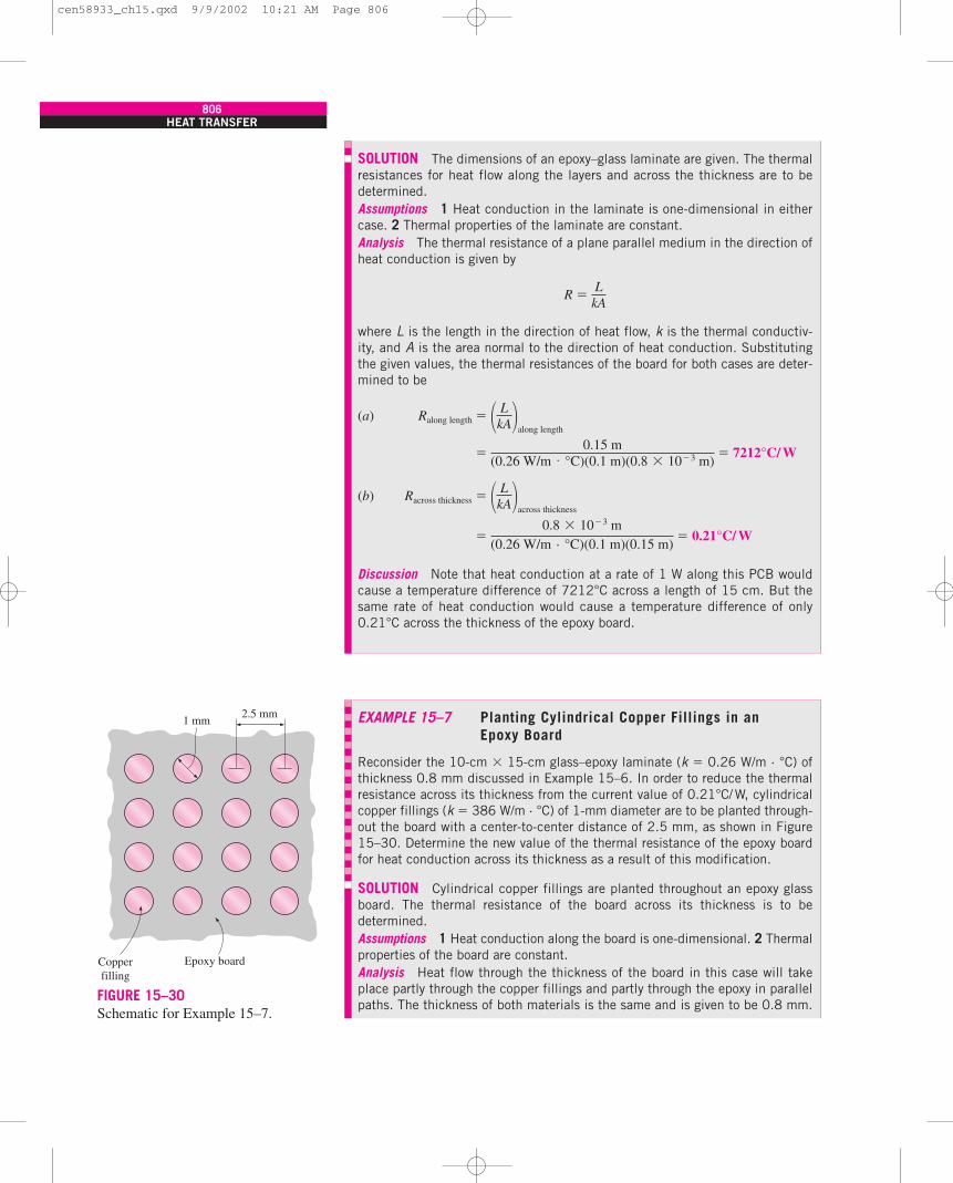
When a heat frame is used, heat conduction in the epoxy layer of the PCBis through its thickness instead of along its length. The epoxy layer in this caseoffers a much smaller resistance to heat flow because of the short distance in-volved. This resistance can be made even smaller by drilling holes in theepoxy and filling them with copper, as shown in Figure 15–28. These copperfillings are usually 1 mm in diameter and their centers are a few millimetersapart. Such highly conductive fillings provide easy passageways for heat fromone side of the PCB to the other and result in considerable reduction in thethermal resistance of the board along its thickness, as shown in Examples15–6, 15-7, and 15–8.
CHAPTER 15805
Discussion Note that a very thin layer of copper cladding on a PCB improvesheat conduction along the PCB drastically, and thus it is commonly used inconduction-cooled electronic devices.
Temperaturedistribution
Electroniccomponents
Heatframe
PCB
Coldplate
Epoxyadhesive
FIGURE 15–27Conduction cooling of a printed
circuit board with a heat frame, andthe typical temperature distribution
along the frame.
EXAMPLE 15–6 Thermal Resistance of an Epoxy Glass Board
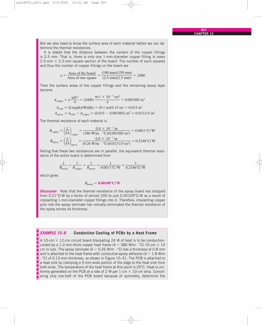
Consider a 10-cm � 15-cm glass–epoxy laminate (k � 0.26 W/m · °C) whosethickness is 0.8 mm, as shown in Figure 15–29. Determine the thermal resis-tance of this epoxy layer for heat flow (a) along the 15-cm-long side and(b) across its thickness.
Copperfillings
Epoxy board
FIGURE 15–28Planting the epoxy board with copper
fillings decreases the thermalresistance across its thickness
considerably.
Epoxy board
15 cm
(a)
(b)
0.8 mm
10 cm
FIGURE 15–29Schematic for Example 15–6.
cen58933_ch15.qxd 9/9/2002 10:21 AM Page 805
806HEAT TRANSFER
SOLUTION The dimensions of an epoxy–glass laminate are given. The thermalresistances for heat flow along the layers and across the thickness are to bedetermined.Assumptions 1 Heat conduction in the laminate is one-dimensional in eithercase. 2 Thermal properties of the laminate are constant.Analysis The thermal resistance of a plane parallel medium in the direction ofheat conduction is given by
R �
where L is the length in the direction of heat flow, k is the thermal conductiv-ity, and A is the area normal to the direction of heat conduction. Substitutingthe given values, the thermal resistances of the board for both cases are deter-mined to be
(a) Ralong length �
� � 7212°C/ W
(b) Racross thickness �
� � 0.21°C/ W
Discussion Note that heat conduction at a rate of 1 W along this PCB wouldcause a temperature difference of 7212°C across a length of 15 cm. But thesame rate of heat conduction would cause a temperature difference of only0.21°C across the thickness of the epoxy board.
0.8 � 10�3 m(0.26 W/m · °C)(0.1 m)(0.15 m)
� LkA�across thickness
0.15 m(0.26 W/m · °C)(0.1 m)(0.8 � 10�3 m)
� LkA�along length
LkA
EXAMPLE 15–7 Planting Cylindrical Copper Fillings in anEpoxy Board
Reconsider the 10-cm � 15-cm glass–epoxy laminate (k � 0.26 W/m · °C) ofthickness 0.8 mm discussed in Example 15–6. In order to reduce the thermalresistance across its thickness from the current value of 0.21°C/W, cylindricalcopper fillings (k � 386 W/m · °C) of 1-mm diameter are to be planted through-out the board with a center-to-center distance of 2.5 mm, as shown in Figure15–30. Determine the new value of the thermal resistance of the epoxy boardfor heat conduction across its thickness as a result of this modification.
SOLUTION Cylindrical copper fillings are planted throughout an epoxy glassboard. The thermal resistance of the board across its thickness is to bedetermined.Assumptions 1 Heat conduction along the board is one-dimensional. 2 Thermalproperties of the board are constant.Analysis Heat flow through the thickness of the board in this case will takeplace partly through the copper fillings and partly through the epoxy in parallelpaths. The thickness of both materials is the same and is given to be 0.8 mm.
1 mm2.5 mm
Copperfilling
Epoxy board
FIGURE 15–30Schematic for Example 15–7.
cen58933_ch15.qxd 9/9/2002 10:21 AM Page 806
CHAPTER 15807
But we also need to know the surface area of each material before we can de-termine the thermal resistances.
It is stated that the distance between the centers of the copper fillingsis 2.5 mm. That is, there is only one 1-mm-diameter copper filling in every2.5-mm � 2.5-mm square section of the board. The number of such squaresand thus the number of copper fillings on the board are
n � � 2400
Then the surface areas of the copper fillings and the remaining epoxy layerbecome
Acopper � n � (2400) � 0.001885 m2
Atotal � (Length)(Width) � (0.1 m)(0.15 m) � 0.015 m2
Aepoxy � Atotal � Acopper � (0.015 � 0.001885) m2 � 0.013115 m2
The thermal resistance of each material is
Rcopper � � 0.0011°C/ W
Repoxy � � 0.2346°C/ W
Noting that these two resistances are in parallel, the equivalent thermal resis-tance of the entire board is determined from
which gives
Rboard � 0.00109°C/ W
Discussion Note that the thermal resistance of the epoxy board has droppedfrom 0.21°C/ W by a factor of almost 200 to just 0.00109°C/ W as a result ofimplanting 1-mm-diameter copper fillings into it. Therefore, implanting copperpins into the epoxy laminate has virtually eliminated the thermal resistance ofthe epoxy across its thickness.
1Rboard
�1
Rcopper�
1Repoxy
�1
0.0011°C/ W�
10.2346°C/ W
� LkA�epoxy
�0.8 � 10�3 m
(0.26 W/m · °C)(0.013115 m2)
� LkA�copper
�0.8 � 10�3 m
(386 W/m · °C)(0.001885 m2)
(1 � 10�3 m)2
4D 2
4
Area of the boardArea of one square
�(100 mm)(150 mm)(2.5 mm)(2.5 mm)
EXAMPLE 15–8 Conduction Cooling of PCBs by a Heat Frame
A 10-cm � 12-cm circuit board dissipating 24 W of heat is to be conduction-cooled by a 1.2-mm-thick copper heat frame (k � 386 W/m · °C) 10 cm � 14cm in size. The epoxy laminate (k � 0.26 W/m · °C) has a thickness of 0.8 mmand is attached to the heat frame with conductive epoxy adhesive (k � 1.8 W/m· °C) of 0.13-mm thickness, as shown in Figure 15–31. The PCB is attached toa heat sink by clamping a 5-mm-wide portion of the edge to the heat sink fromboth ends. The temperature of the heat frame at this point is 20°C. Heat is uni-formly generated on the PCB at a rate of 2 W per 1-cm � 10-cm strip. Consid-ering only one-half of the PCB board because of symmetry, determine the
cen58933_ch15.qxd 9/9/2002 10:21 AM Page 807
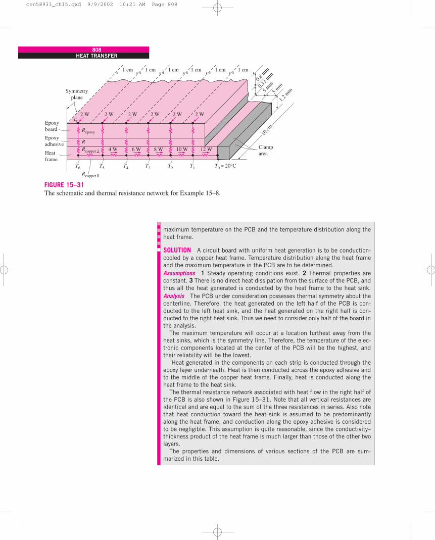
808HEAT TRANSFER
maximum temperature on the PCB and the temperature distribution along theheat frame.
SOLUTION A circuit board with uniform heat generation is to be conduction-cooled by a copper heat frame. Temperature distribution along the heat frameand the maximum temperature in the PCB are to be determined.Assumptions 1 Steady operating conditions exist. 2 Thermal properties areconstant. 3 There is no direct heat dissipation from the surface of the PCB, andthus all the heat generated is conducted by the heat frame to the heat sink.Analysis The PCB under consideration possesses thermal symmetry about thecenterline. Therefore, the heat generated on the left half of the PCB is con-ducted to the left heat sink, and the heat generated on the right half is con-ducted to the right heat sink. Thus we need to consider only half of the board inthe analysis.
The maximum temperature will occur at a location furthest away from theheat sinks, which is the symmetry line. Therefore, the temperature of the elec-tronic components located at the center of the PCB will be the highest, andtheir reliability will be the lowest.
Heat generated in the components on each strip is conducted through theepoxy layer underneath. Heat is then conducted across the epoxy adhesive andto the middle of the copper heat frame. Finally, heat is conducted along theheat frame to the heat sink.
The thermal resistance network associated with heat flow in the right half ofthe PCB is also shown in Figure 15–31. Note that all vertical resistances areidentical and are equal to the sum of the three resistances in series. Also notethat heat conduction toward the heat sink is assumed to be predominantlyalong the heat frame, and conduction along the epoxy adhesive is consideredto be negligible. This assumption is quite reasonable, since the conductivity–thickness product of the heat frame is much larger than those of the other twolayers.
The properties and dimensions of various sections of the PCB are sum-marized in this table.
FIGURE 15–31The schematic and thermal resistance network for Example 15–8.
1 cm 1 cm 1 cm 1 cm 1 cm 1 cm
0.8 m
m0.1
3 mm
5 mm
1.2 m
m5 mm
10 cm
Clamparea
2 W
Symmetryplane
T6
T7
Repoxy
Rcopper I
Rcopper II
R
T5 T4 T3 T2 T1 T0 = 20°C
12 W10 W8 W6 W4 W
2 W 2 W 2 W 2 W 2 W
Epoxyboard
Heatframe
Epoxyadhesive
cen58933_ch15.qxd 9/9/2002 10:21 AM Page 808
CHAPTER 15809
Thermal Section and Conductivity, Thickness, Heat Transfer Material W/m · °C mm Surface area
Epoxy board 0.26 0.8 10 mm � 100 mmEpoxy adhesive 1.8 0.13 10 mm � 100 mmCopper heat frame, �
(normal to frame) 386 0.6 10 mm � 100 mmCopper heat frame, �
(along the frame) 386 10 1.2 mm � 100 mm
Using the values in the table, the various thermal resistances are determinedto be
Repoxy � � 3.077°C/ W
Radhesive � � 0.072°C/ W
Rcopper, � � � 0.002°C/ W
Rframe � Rcopper, � �
� 0.216°C/ W
The combined resistance between the electronic components on each stripand the heat frame can be determined, by adding the three resistances in se-ries, to be
Rvertical � Repoxy � Radhesive � Rcopper, �
� (3.077 � 0.072 � 0.002)°C/ W
� 3.151°C/ W
The various temperatures along the heat frame can be determined from therelation
�T � Thigh � Tlow � Q·R
where R is the thermal resistance between two specified points, Q·
is the heattransfer rate through that resistance, and �T is the temperature differenceacross that resistance.
The temperature at the location where the heat frame is clamped to the heatsink is given as T0 � 20°C. Noting that the entire 12 W of heat generated onthe right half of the PCB must pass through the last thermal resistance adjacentto the heat sink, the temperature T1 can be determined from
T1 � T0 � Q·
1–0 R1–0 � 20°C � (12 W)(0.216°C/ W) � 22.59°C
Following the same line of reasoning, the temperatures at specified locationsalong the heat frame are determined to be
T2 � T1 � Q·
2–1 R2–1 � 22.59°C � (10 W)(0.216°C/ W) � 24.75°C
T3 � T2 � Q·
3–2 R3–2 � 24.75°C � (8 W)(0.216°C/ W) � 26.48°C
T4 � T3 � Q·
4–3 R4–3 � 26.48°C � (6 W)(0.216°C/ W) � 27.78°C
T5 � T4 � Q·
5–4 R5–4 � 27.78°C � (4 W)(0.216°C/ W) � 28.64°C
T6 � T5 � Q·
6–5 R6–5 � 28.64°C � (2 W)(0.216°C/ W) � 29.07°C
� LkA�copper, �
�0.01 m
(386 W/m · °C)(0.0012 m � 0.1 m)
� LkA�copper, _�
�0.6 � 10�3 m
(386 W/m · °C)(0.01 m � 0.1 m)
� LkA�adhesive
�0.13 � 10�3 m
(1.8 W/m · °C)(0.01 m � 0.1 m)
� LkA�epoxy
�0.8 � 10�3 m
(0.26 W/m · °C)(0.01 m � 0.1 m)
cen58933_ch15.qxd 9/9/2002 10:21 AM Page 809
Conduction cooling can also be used when electronic components aremounted on both sides of the PCB by using a copper or aluminum core platein the middle of the PCB, as shown in Figure 15–32. The heat load in this casewill be twice that of a PCB that has components on one side only. Again, heatgenerated in the components will be conducted through the thickness of theepoxy layer to the metal core, which serves as a channel for effective heatremoval. The thickness of the core is selected such that the maximum com-ponent temperatures remain below specified values to meet a prescribed reli-ability criterion.
The thermal expansion coefficients of aluminum and copper are about twiceas large as that of the glass–epoxy. This large difference in thermal expansioncoefficients can cause warping on the PCBs if the epoxy and the metal are notbonded properly. One way of avoiding warping is to use PCBs with compo-nents on both sides, as discussed. Extreme care should be exercised during thebonding and curing process when components are mounted on only one sideof the PCB.
The Thermal Conduction Module (TCM)The heat flux for logic chips has been increasing steadily as a result of theincreasing circuit density in the chips. For example, the peak flux at the chiplevel has increased from 2 W/cm2 on IBM System 370 to 20 W/cm2 on IBMSystem 3081, which was introduced in the early 1980s. The conventionalforced-air cooling technique used in earlier machines was inadequate for re-moving such high heat fluxes, and it was necessary to develop a new andmore effective cooling technique. The result was the thermal conductionmodule, shown in Figure 15–33. The TCM was different from previous chippackaging designs in that it incorporated both electrical and thermal consider-ations in early stages of chip design. Previously, a chip would be designed pri-marily by electrical designers, and the thermal designer would be told to comeup with a cooling scheme for the chip. That approach resulted in unnecessar-ily high junction temperatures, and reduced reliability, since the thermal de-signer had no direct access to the chip. The TCM reflects a new philosophy inelectronic packaging in that the thermal and electrical aspects are given equaltreatment in the design process, and a successful thermal design starts at thechip level.
810HEAT TRANSFER
Finally, T7, which is the maximum temperature on the PCB, is determined from
T7 � T6 � Q·
vertical Rvertical � 29.07°C � (2 W)(3.151°C/ W) � 35.37°C
Discussion The maximum temperature difference between the PCB and theheat sink is only 15.37°C, which is very impressive considering that the PCBhas no direct contact with the cooling medium. The junction temperatures inthis case can be determined by calculating the temperature difference betweenthe junction and the leads of the chip carrier at the point of contact to the PCBand adding 35.37°C to it. The maximum temperature rise of 15.37°C can bereduced, if necessary, by using a thicker heat frame.
Metal core
Epoxylamina
Electroniccomponents
Heatsink
FIGURE 15–32A two-sided printed circuit board witha metal core for conduction cooling.
cen58933_ch15.qxd 9/9/2002 10:21 AM Page 810
In the TCM, one side of the chip is reserved for electrical connections andthe other side for heat rejection. The chip is cooled by direct contact to thecooling system to minimize the junction-to-case thermal resistance.
The TCM houses 100 to 118 logic chips, which are bonded to a multilayerceramic substrate 90 mm � 90 mm in size with solder balls, which also pro-vide the electrical connections between the chips and the substrate. Each chipdissipates about 4 W of power. The heat flow path from the chip to the metalcasing is provided by a piston, which is pressed against the back surface of thechip by a spring. The tip of the piston is slightly curved to ensure good ther-mal contact even when the chip is tilted or misaligned.
Heat conduction between the chip and the piston occurs primarily throughthe gas space between the chip and the piston because of the limited contactarea between them. To maximize heat conduction through the gas, the air inthe TCM cavity is evacuated and is replaced by helium gas, whose thermalconductivity is about six times that of air. Heat is then conducted through thepiston, across the surrounding helium gas layer, through the module housing,and finally to the cooling water circulating through the cold plate attached tothe top surface of the TCM.
The total internal thermal resistance Rint of the TCM is about 8°C/W, whichis rather impressive. This means that the temperature difference between thechip surface and the outer surface of the housing of the module will be only24°C for a 3-W chip. The external thermal resistance Rext between the hous-ing of the module and the cooling fluid is usually comparable in magnitude toRint. Also, the thermal resistance between the junction and the surface of thechip can be taken to be 1°C/W.
CHAPTER 15811
FIGURE 15–33Cutaway view of the thermal conduction module (TCM), and the thermal resistance network between a single chip and the
cooling fluid (courtesy of IBM Corporation).
Piston
C-ring seal
Heliumreservoir
Spring
Chip
Ceramicsubstrate
Rt
Rp–h
Rc–p
Rp–w
Rint
Rext
Rw–h
Rgp
Rc
Helium(or gas mixture)
Interposer
Cold plateCoolingmedium
Hat
Chip
Substrate
Sphericalradius
Piston
Cold plate
cen58933_ch15.qxd 9/9/2002 10:21 AM Page 811
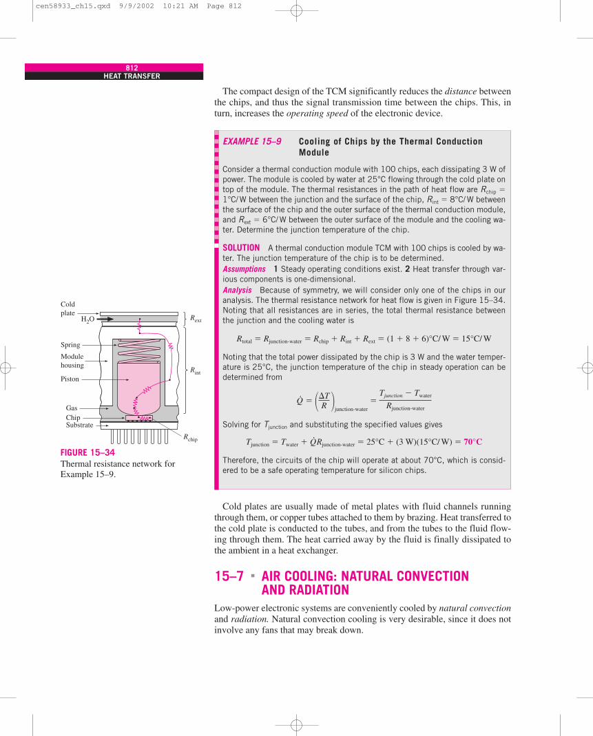
The compact design of the TCM significantly reduces the distance betweenthe chips, and thus the signal transmission time between the chips. This, inturn, increases the operating speed of the electronic device.
812HEAT TRANSFER
EXAMPLE 15–9 Cooling of Chips by the Thermal ConductionModule
Consider a thermal conduction module with 100 chips, each dissipating 3 W ofpower. The module is cooled by water at 25°C flowing through the cold plate ontop of the module. The thermal resistances in the path of heat flow are Rchip �1°C/W between the junction and the surface of the chip, Rint � 8°C/W betweenthe surface of the chip and the outer surface of the thermal conduction module,and Rext � 6°C/W between the outer surface of the module and the cooling wa-ter. Determine the junction temperature of the chip.
SOLUTION A thermal conduction module TCM with 100 chips is cooled by wa-ter. The junction temperature of the chip is to be determined.Assumptions 1 Steady operating conditions exist. 2 Heat transfer through var-ious components is one-dimensional.Analysis Because of symmetry, we will consider only one of the chips in ouranalysis. The thermal resistance network for heat flow is given in Figure 15–34.Noting that all resistances are in series, the total thermal resistance betweenthe junction and the cooling water is
Rtotal � Rjunction-water � Rchip � Rint � Rext � (1 � 8 � 6)°C/ W � 15°C/ W
Noting that the total power dissipated by the chip is 3 W and the water temper-ature is 25°C, the junction temperature of the chip in steady operation can bedetermined from
Q·
�
Solving for Tjunction and substituting the specified values gives
Tjunction � Twater � Q·Rjunction-water � 25°C � (3 W)(15°C/ W) � 70°C
Therefore, the circuits of the chip will operate at about 70°C, which is consid-ered to be a safe operating temperature for silicon chips.
��TR �
junction-water�
Tjunction � Twater
Rjunction-water
Cold plates are usually made of metal plates with fluid channels runningthrough them, or copper tubes attached to them by brazing. Heat transferred tothe cold plate is conducted to the tubes, and from the tubes to the fluid flow-ing through them. The heat carried away by the fluid is finally dissipated tothe ambient in a heat exchanger.
15–7 AIR COOLING: NATURAL CONVECTIONAND RADIATION
Low-power electronic systems are conveniently cooled by natural convectionand radiation. Natural convection cooling is very desirable, since it does notinvolve any fans that may break down.
�
Coldplate
Spring
H2O
Piston
Gas
Rint
Rext
Rchip
ChipSubstrate
Modulehousing
FIGURE 15–34Thermal resistance network forExample 15–9.
cen58933_ch15.qxd 9/9/2002 10:21 AM Page 812
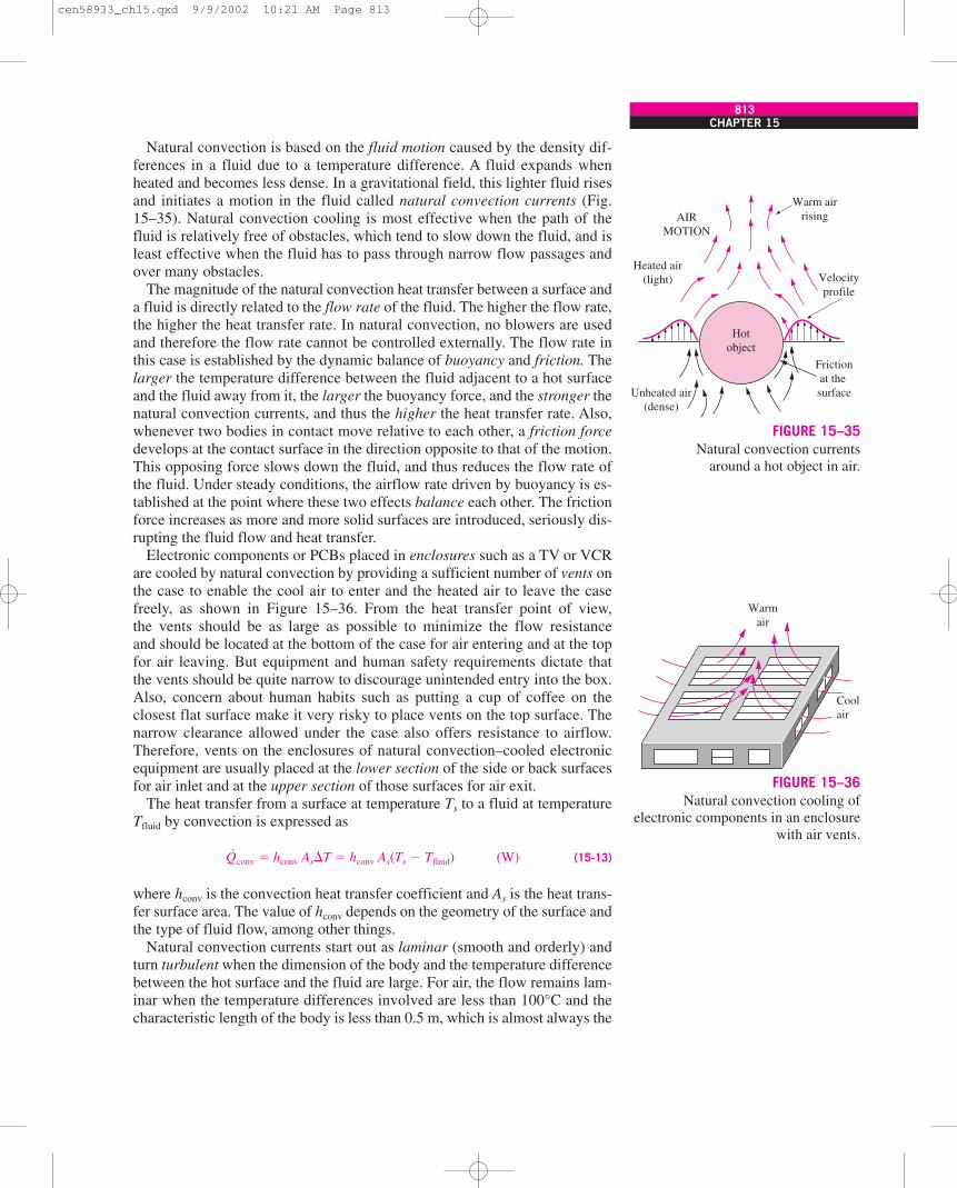
Natural convection is based on the fluid motion caused by the density dif-ferences in a fluid due to a temperature difference. A fluid expands whenheated and becomes less dense. In a gravitational field, this lighter fluid risesand initiates a motion in the fluid called natural convection currents (Fig.15–35). Natural convection cooling is most effective when the path of thefluid is relatively free of obstacles, which tend to slow down the fluid, and isleast effective when the fluid has to pass through narrow flow passages andover many obstacles.
The magnitude of the natural convection heat transfer between a surface anda fluid is directly related to the flow rate of the fluid. The higher the flow rate,the higher the heat transfer rate. In natural convection, no blowers are usedand therefore the flow rate cannot be controlled externally. The flow rate inthis case is established by the dynamic balance of buoyancy and friction. Thelarger the temperature difference between the fluid adjacent to a hot surfaceand the fluid away from it, the larger the buoyancy force, and the stronger thenatural convection currents, and thus the higher the heat transfer rate. Also,whenever two bodies in contact move relative to each other, a friction forcedevelops at the contact surface in the direction opposite to that of the motion.This opposing force slows down the fluid, and thus reduces the flow rate ofthe fluid. Under steady conditions, the airflow rate driven by buoyancy is es-tablished at the point where these two effects balance each other. The frictionforce increases as more and more solid surfaces are introduced, seriously dis-rupting the fluid flow and heat transfer.
Electronic components or PCBs placed in enclosures such as a TV or VCRare cooled by natural convection by providing a sufficient number of vents onthe case to enable the cool air to enter and the heated air to leave the casefreely, as shown in Figure 15–36. From the heat transfer point of view,the vents should be as large as possible to minimize the flow resistanceand should be located at the bottom of the case for air entering and at the topfor air leaving. But equipment and human safety requirements dictate thatthe vents should be quite narrow to discourage unintended entry into the box.Also, concern about human habits such as putting a cup of coffee on theclosest flat surface make it very risky to place vents on the top surface. Thenarrow clearance allowed under the case also offers resistance to airflow.Therefore, vents on the enclosures of natural convection–cooled electronicequipment are usually placed at the lower section of the side or back surfacesfor air inlet and at the upper section of those surfaces for air exit.
The heat transfer from a surface at temperature Ts to a fluid at temperatureTfluid by convection is expressed as
Q·
conv � hconv As�T � hconv As(Ts � Tfluid) (W) (15-13)
where hconv is the convection heat transfer coefficient and As is the heat trans-fer surface area. The value of hconv depends on the geometry of the surface andthe type of fluid flow, among other things.
Natural convection currents start out as laminar (smooth and orderly) andturn turbulent when the dimension of the body and the temperature differencebetween the hot surface and the fluid are large. For air, the flow remains lam-inar when the temperature differences involved are less than 100°C and thecharacteristic length of the body is less than 0.5 m, which is almost always the
CHAPTER 15813
Hotobject
Frictionat the surface
Velocityprofile
Warm airrisingAIR
MOTION
Heated air(light)
Unheated air(dense)
FIGURE 15–35Natural convection currents
around a hot object in air.
Coolair
Warmair
FIGURE 15–36Natural convection cooling of
electronic components in an enclosurewith air vents.
cen58933_ch15.qxd 9/9/2002 10:21 AM Page 813
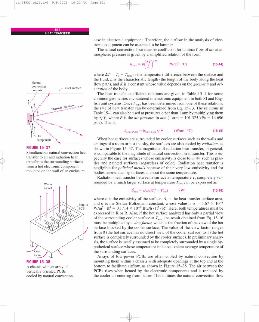
case in electronic equipment. Therefore, the airflow in the analysis of elec-tronic equipment can be assumed to be laminar.
The natural convection heat transfer coefficient for laminar flow of air at at-mospheric pressure is given by a simplified relation of the form
hconv � K (W/m2 · °C) (15-14)
where �T � Ts � Tfluid is the temperature difference between the surface andthe fluid, L is the characteristic length (the length of the body along the heatflow path), and K is a constant whose value depends on the geometry and ori-entation of the body.
The heat transfer coefficient relations are given in Table 15–1 for somecommon geometries encountered in electronic equipment in both SI and Eng-lish unit systems. Once hconv has been determined from one of these relations,the rate of heat transfer can be determined from Eq. 15-13. The relations inTable 15–1 can also be used at pressures other than 1 atm by multiplying themby , where P is the air pressure in atm (1 atm � 101.325 kPa � 14.696psia). That is,
hconv, P atm � hconv, 1 atm (W/m2 · °C) (15-15)
When hot surfaces are surrounded by cooler surfaces such as the walls andceilings of a room or just the sky, the surfaces are also cooled by radiation, asshown in Figure 15–37. The magnitude of radiation heat transfer, in general,is comparable to the magnitude of natural convection heat transfer. This is es-pecially the case for surfaces whose emissivity is close to unity, such as plas-tics and painted surfaces (regardless of color). Radiation heat transfer isnegligible for polished metals because of their very low emissivity and forbodies surrounded by surfaces at about the same temperature.
Radiation heat transfer between a surface at temperature Ts completely sur-rounded by a much larger surface at temperature Tsurr can be expressed as
Q·
rad � As �(T 4s � T 4
surr) (W) (15-16)
where is the emissivity of the surface, As is the heat transfer surface area,and � is the Stefan–Boltzmann constant, whose value is � � 5.67 � 10�8
W/m2 · K4 � 0.1714 � 10�8 Btu/h · ft2 · R4. Here, both temperatures must beexpressed in K or R. Also, if the hot surface analyzed has only a partial viewof the surrounding cooler surface at Tsurr, the result obtained from Eq. 15-16must be multiplied by a view factor, which is the fraction of the view of the hotsurface blocked by the cooler surface. The value of the view factor rangesfrom 0 (the hot surface has no direct view of the cooler surface) to 1 (the hotsurface is completely surrounded by the cooler surface). In preliminary analy-sis, the surface is usually assumed to be completely surrounded by a single hy-pothetical surface whose temperature is the equivalent average temperature ofthe surrounding surfaces.
Arrays of low-power PCBs are often cooled by natural convection bymounting them within a chassis with adequate openings at the top and at thebottom to facilitate airflow, as shown in Figure 15–38. The air between thePCBs rises when heated by the electronic components and is replaced bythe cooler air entering from below. This initiates the natural convection flow
�P
�P
��TL �
0.25
814HEAT TRANSFER
Cool surface
Hotcomponent
Naturalconvectioncurrents
Thermal radiation
FIGURE 15–37Simultaneous natural convection heattransfer to air and radiation heattransfer to the surrounding surfacesfrom a hot electronic componentmounted on the wall of an enclosure.
Plug-inPCB
Coolair in
Warmair out
FIGURE 15–38A chassis with an array ofvertically oriented PCBscooled by natural convection.
cen58933_ch15.qxd 9/9/2002 10:21 AM Page 814
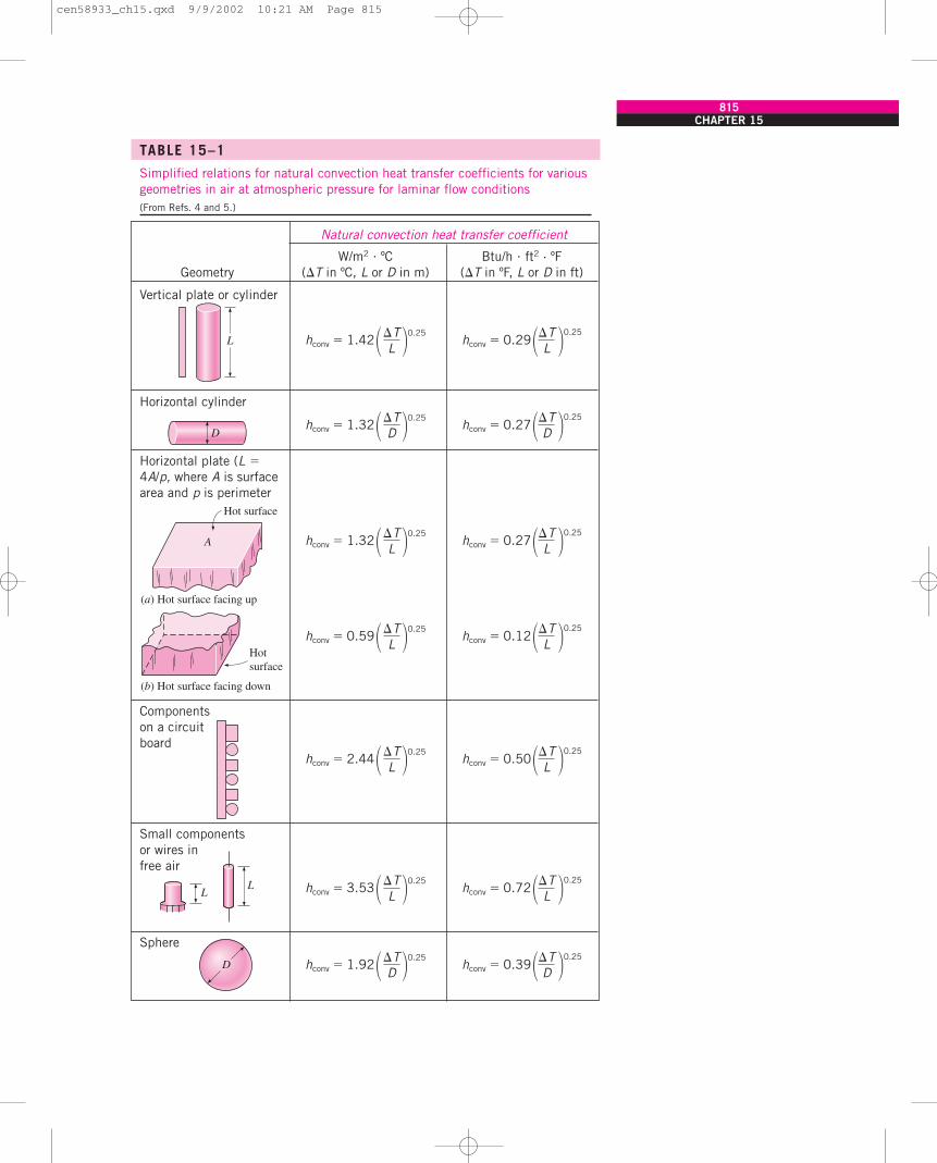
CHAPTER 15815
TABLE 15–1
Simplified relations for natural convection heat transfer coefficients for variousgeometries in air at atmospheric pressure for laminar flow conditions(From Refs. 4 and 5.)
Natural convection heat transfer coefficient
W/m2 � ºC Btu/h � ft2 · ºFGeometry (�T in ºC, L or D in m) (�T in ºF, L or D in ft)
Vertical plate or cylinder
Horizontal cylinder
Horizontal plate (L �4A/p, where A is surface area and p is perimeter
Components on a circuit board
Small componentsor wires in free air
Sphere
hconv � 0.39��TD �0.25
hconv � 1.92��TD �0.25
D
LL hconv � 0.72��T
L �0.25hconv � 3.53��T
L �0.25
hconv � 0.50��TL �0.25
hconv � 2.44��TL �0.25
hconv � 0.12��TL �0.25
hconv � 0.59��TL �0.25
hconv � 0.27��TL �0.25
hconv � 1.32��TL �0.25
(a) Hot surface facing up
(b) Hot surface facing down
A
Hot surface
Hotsurface
hconv � 0.27��TD �0.25
hconv � 1.32��TD �0.25
D
hconv � 0.29��TL �0.25
hconv � 1.42��TL �0.25
L
cen58933_ch15.qxd 9/9/2002 10:21 AM Page 815
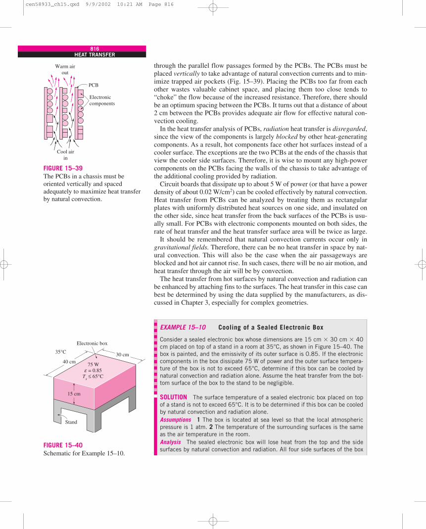
through the parallel flow passages formed by the PCBs. The PCBs must beplaced vertically to take advantage of natural convection currents and to min-imize trapped air pockets (Fig. 15–39). Placing the PCBs too far from eachother wastes valuable cabinet space, and placing them too close tends to“choke” the flow because of the increased resistance. Therefore, there shouldbe an optimum spacing between the PCBs. It turns out that a distance of about2 cm between the PCBs provides adequate air flow for effective natural con-vection cooling.
In the heat transfer analysis of PCBs, radiation heat transfer is disregarded,since the view of the components is largely blocked by other heat-generatingcomponents. As a result, hot components face other hot surfaces instead of acooler surface. The exceptions are the two PCBs at the ends of the chassis thatview the cooler side surfaces. Therefore, it is wise to mount any high-powercomponents on the PCBs facing the walls of the chassis to take advantage ofthe additional cooling provided by radiation.
Circuit boards that dissipate up to about 5 W of power (or that have a powerdensity of about 0.02 W/cm2) can be cooled effectively by natural convection.Heat transfer from PCBs can be analyzed by treating them as rectangularplates with uniformly distributed heat sources on one side, and insulated onthe other side, since heat transfer from the back surfaces of the PCBs is usu-ally small. For PCBs with electronic components mounted on both sides, therate of heat transfer and the heat transfer surface area will be twice as large.
It should be remembered that natural convection currents occur only ingravitational fields. Therefore, there can be no heat transfer in space by nat-ural convection. This will also be the case when the air passageways areblocked and hot air cannot rise. In such cases, there will be no air motion, andheat transfer through the air will be by convection.
The heat transfer from hot surfaces by natural convection and radiation canbe enhanced by attaching fins to the surfaces. The heat transfer in this case canbest be determined by using the data supplied by the manufacturers, as dis-cussed in Chapter 3, especially for complex geometries.
816HEAT TRANSFER
Warm airout
Cool airin
Electroniccomponents
PCB
FIGURE 15–39The PCBs in a chassis must beoriented vertically and spacedadequately to maximize heat transferby natural convection.
EXAMPLE 15–10 Cooling of a Sealed Electronic Box
Consider a sealed electronic box whose dimensions are 15 cm � 30 cm � 40cm placed on top of a stand in a room at 35°C, as shown in Figure 15–40. Thebox is painted, and the emissivity of its outer surface is 0.85. If the electroniccomponents in the box dissipate 75 W of power and the outer surface tempera-ture of the box is not to exceed 65°C, determine if this box can be cooled bynatural convection and radiation alone. Assume the heat transfer from the bot-tom surface of the box to the stand to be negligible.
SOLUTION The surface temperature of a sealed electronic box placed on topof a stand is not to exceed 65°C. It is to be determined if this box can be cooledby natural convection and radiation alone.Assumptions 1 The box is located at sea level so that the local atmosphericpressure is 1 atm. 2 The temperature of the surrounding surfaces is the sameas the air temperature in the room.Analysis The sealed electronic box will lose heat from the top and the sidesurfaces by natural convection and radiation. All four side surfaces of the box
35°C
15 cm
Stand
40 cm30 cm
75 W = 0.85 ≤ 65°C
εTs
Electronic box
FIGURE 15–40Schematic for Example 15–10.
cen58933_ch15.qxd 9/9/2002 10:21 AM Page 816
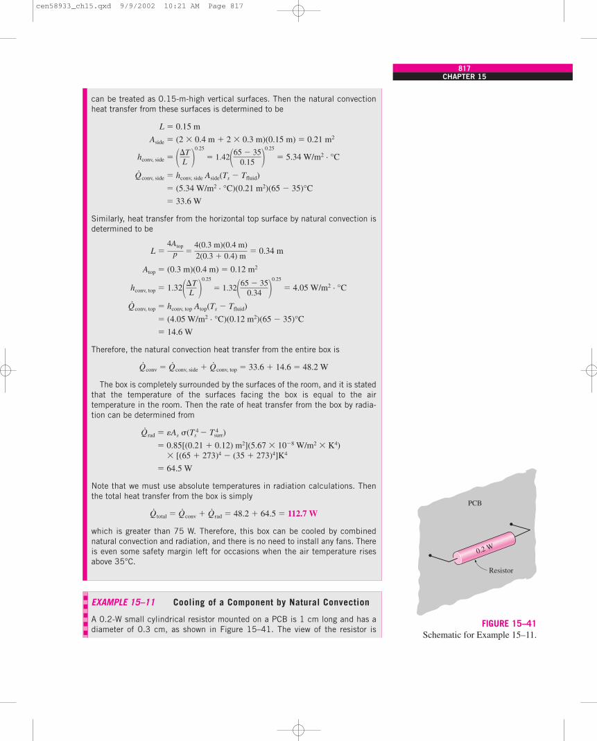
CHAPTER 15817
can be treated as 0.15-m-high vertical surfaces. Then the natural convectionheat transfer from these surfaces is determined to be
L � 0.15 m
Aside � (2 � 0.4 m � 2 � 0.3 m)(0.15 m) � 0.21 m2
hconv, side � � 5.34 W/m2 · °C
Q·
conv, side � hconv, side Aside(Ts � Tfluid)
� (5.34 W/m2 · °C)(0.21 m2)(65 � 35)°C
� 33.6 W
Similarly, heat transfer from the horizontal top surface by natural convection isdetermined to be
L � � 0.34 m
Atop � (0.3 m)(0.4 m) � 0.12 m2
hconv, top � 1.32 � 4.05 W/m2 · °C
Q·
conv, top � hconv, top Atop(Ts � Tfluid)
� (4.05 W/m2 · °C)(0.12 m2)(65 � 35)°C
� 14.6 W
Therefore, the natural convection heat transfer from the entire box is
Q·
conv � Q·
conv, side � Q·
conv, top � 33.6 � 14.6 � 48.2 W
The box is completely surrounded by the surfaces of the room, and it is statedthat the temperature of the surfaces facing the box is equal to the airtemperature in the room. Then the rate of heat transfer from the box by radia-tion can be determined from
Q·
rad � As �(T 4s � T 4
surr)
� 0.85[(0.21 � 0.12) m2](5.67 � 10�8 W/m2 � K4)� [(65 � 273)4 � (35 � 273)4]K4
� 64.5 W
Note that we must use absolute temperatures in radiation calculations. Thenthe total heat transfer from the box is simply
Q·
total � Q·
conv � Q·
rad � 48.2 � 64.5 � 112.7 W
which is greater than 75 W. Therefore, this box can be cooled by combinednatural convection and radiation, and there is no need to install any fans. Thereis even some safety margin left for occasions when the air temperature risesabove 35°C.
��TL �
0.25
� 1.32�65 � 350.34 �
0.25
4Atop
p �4(0.3 m)(0.4 m)2(0.3 � 0.4) m
��TL �
0.25
� 1.42�65 � 350.15 �
0.25
EXAMPLE 15–11 Cooling of a Component by Natural Convection
A 0.2-W small cylindrical resistor mounted on a PCB is 1 cm long and has adiameter of 0.3 cm, as shown in Figure 15–41. The view of the resistor is
Resistor
PCB
0.2 W
FIGURE 15–41Schematic for Example 15–11.
cen58933_ch15.qxd 9/9/2002 10:21 AM Page 817
818HEAT TRANSFER
largely blocked by the PCB facing it, and the heat transfer from the connectingwires is negligible. The air is free to flow through the parallel flow passages be-tween the PCBs. If the air temperature at the vicinity of the resistor is 50°C, de-termine the surface temperature of the resistor.
SOLUTION A small cylindrical resistor mounted on a PCB is being cooled bynatural convection and radiation. The surface temperature of the resistor is tobe determined.Assumptions 1 Steady operating conditions exist. 2 The device is located atsea level so that the local atmospheric pressure is 1 atm. 3 Radiation is negli-gible in this case since the resistor is surrounded by surfaces that are at aboutthe same temperature, and the net radiation heat transfer between two surfacesat the same temperature is zero. This leaves natural convection as the onlymechanism of heat transfer from the resistor.Analysis Using the relation for components on a circuit board from Table15–1, the natural convection heat transfer coefficient for this cylindrical com-ponent can be determined from
hconv � 2.44
where the diameter D � 0.003 m, which is the length in the heat flow path, isthe characteristic length. We cannot determine hconv yet since we do not knowthe surface temperature of the component and thus �T. But we can substitutethis relation into the heat transfer relation to get
Q·
conv � hconv As(Ts � Tfluid) � 2.44 A(Ts � Tfluid)
� 2.44As
The heat transfer surface area of the component is
As � 2 � D 2 � DL � 2 � (0.3 cm)2 � (0.3 cm)(1 cm) � 1.084 cm2
Substituting this and other known quantities in proper units (W for Q·, °C for T,
m2 for A, and m for D) into this equation and solving for Ts yields
0.2 � 2.44(1.084 � 10�4) → Ts � 113°C
Therefore, the surface temperature of the resistor on the PCB will be 113°C,which is considered to be a safe operating temperature for the resistors. Notethat blowing air to the circuit board will lower this temperature considerably as aresult of increasing the convection heat transfer coefficient and decreasing theair temperature at the vicinity of the components due to the larger flow rate of air.
(Ts � 50)1.25
0.0030.25
14
14
(Ts � Tfluid)1.25
D 0.25
�Ts � Tfluid
D �0.25
�Ts � Tfluid
D �0.25
EXAMPLE 15–12 Cooling of a PCB in a Box by Natural Convection
A 15-cm � 20-cm PCB has electronic components on one side, dissipating atotal of 7 W, as shown in Figure 15–42. The PCB is mounted in a rack verticallytogether with other PCBs. If the surface temperature of the components is notto exceed 100°C, determine the maximum temperature of the environment in
7 WPCB
20 cm
15 cm
FIGURE 15–42Schematic for Example 15–12.
cen58933_ch15.qxd 9/9/2002 10:21 AM Page 818
CHAPTER 15819
which this PCB can operate safely at sea level. What would your answer be ifthis rack is located at a location at 4000 m altitude where the atmosphericpressure is 61.66 kPa?
SOLUTION The surface temperature of a PCB is not to exceed 100°C. Themaximum environment temperatures for safe operaton at sea level and at 4000m altitude are to be determined.Assumptions 1 Steady operating conditions exist. 2 Radiation heat transferis negligible since the PCB is surrounded by other PCBs at about the same tem-perature. 3 Heat transfer from the back surface of the PCB will be very smalland thus negligible.Analysis The entire heat load of the PCB is dissipated to the ambient air by nat-ural convection from its front surface, which can be treated as a vertical flat plate.
Using the simplified relation for a vertical surface from Table 15–1, the nat-ural convection heat transfer coefficient for this PCB can be determined from
hconv � 1.42
The characteristic length in this case is the height (L � 0.15 m) of the PCB,which is the length in the path of heat flow. We cannot determine hconv yet,since we do not know the ambient temperature and thus �T. But we can sub-stitute this relation into the heat transfer relation to get
Q·
conv � hconv As(Ts � Tfluid) � 1.42 A(Ts � Tfluid)
� 1.42As
The heat transfer surface area of the PCB is
As � (Width)(Height) � (0.2 m)(0.15 m) � 0.03 m2
Substituting this and other known quantities in proper units (W for Q·, °C for T,
m2 for As, and m for L) into this equation and solving for Tfluid yields
7 � 1.42(0.03) → Tfluid � 59.5°C
Therefore, the PCB will operate safely in environments with temperatures up to59.4°C by relying solely on natural convection.
At an altitude of 4000 m, the atmospheric pressure is 61.66 kPa, which isequivalent to
P � (61.66 kPa) � 0.609 atm
The heat transfer coefficient in this case is obtained by multiplying the value atsea level by , where P is in atm. Substituting
7 � 1.42(0.03) → Tfluid � 50.6°C
which is about 10°C lower than the value obtained at 1 atm pressure. There-fore, the effect of altitude on convection should be considered in high-altitudeapplications.
(100 � Tfluid)1.25
0.150.25 �0.609
�P
1 atm101.325 kPa
(100 � Tfluid)1.25
0.150.25
(Ts � Tfluid)1.25
L 0.25
�Ts � Tfluid
L �0.25
��TL �
0.25
� 1.42�Ts � Tfluid
L �0.25
cen58933_ch15.qxd 9/9/2002 10:21 AM Page 819
15–8 AIR COOLING: FORCED CONVECTIONWe mentioned earlier that convection heat transfer between a solid surfaceand a fluid is proportional to the velocity of the fluid. The higher the velocity,the larger the flow rate and the higher the heat transfer rate. The fluid veloci-ties associated with natural convection currents are naturally low, and thusnatural convection cooling is limited to low-power electronic systems.
When natural convection cooling is not adequate, we simply add a fan andblow air through the enclosure that houses the electronic components. In otherwords, we resort to forced convection in order to enhance the velocity and thusthe flow rate of the fluid as well as the heat transfer. By doing so, we can in-crease the heat transfer coefficient by a factor of up to about 10, depending onthe size of the fan. This means we can remove heat at much higher rates for aspecified temperature difference between the components and the air, or wecan reduce the surface temperature of the components considerably for a spec-ified power dissipation.
The radiation heat transfer in forced-convection-cooled electronic systemsis usually disregarded for two reasons. First, forced convection heat transferis usually much larger than that due to radiation, and the consideration of ra-diation causes no significant change in the results. Second, the electroniccomponents and circuit boards in convection-cooled systems are mounted soclose to each other that a component is almost entirely surrounded by othercomponents at about the same high temperature. That is, the components havehardly any direct view of a cooler surface. This results in little or no radiationheat transfer from the components. The components near the edges of circuitboards with a large view of a cooler surface may benefit somewhat from theadditional cooling by radiation, and it is a good design practice to reservethose spots for high-power components to have a thermally balanced system.
When heat transfer from the outer surface of the enclosure of the electronicequipment is negligible, the amount of heat absorbed by the air becomes equalto the amount of heat rejected (or power dissipated) by the electronic compo-nents in the enclosure, and can be expressed as (Fig. 15–43)
Q·
� m· Cp(Tout � Tin) (W) (15-17)
where Q·
is the rate of heat transfer to the air; Cp is the specific heat of air;Tin and Tout are the average temperatures of air at the inlet and exit of theenclosure, respectively; and m· is the mass flow rate of air.
Note that for a specified mass flow rate and power dissipation, the temper-ature rise of air, Tout � Tin, remains constant as it flows through the enclosure.Therefore, the higher the inlet temperature of the air, the higher the exit tem-perature, and thus the higher the surface temperature of the components. It isconsidered a good design practice to limit the temperature rise of air to 10°Cand the maximum exit temperature of air to 70°C. In a properly designedforced-air-cooled system, this results in a maximum component surface tem-perature of under 100°C.
The mass flow rate of air required for cooling an electronic box depends onthe temperature of air available for cooling. In cool environments, such as anair-conditioned room, a smaller flow rate will be adequate. However, in hotenvironments, we may need to use a larger flow rate to avoid overheating thecomponents and the potential problems associated with it.
�
820HEAT TRANSFER
Power consumed:
Air inlet
Fan
Electroniccomponents
Tin
Qloss≈ 0
Welectric = Qabsorbed = mCp(Tout – Tin)
.
...
Tout
Airexit
FIGURE 15–43In steady operation, the heat absorbedby air per unit time as it flows throughan electronic box is equal to the powerconsumed by the electroniccomponents in the box.
cen58933_ch15.qxd 9/9/2002 10:21 AM Page 820
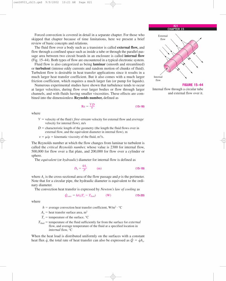
Forced convection is covered in detail in a separate chapter. For those whoskipped that chapter because of time limitations, here we present a briefreview of basic concepts and relations.
The fluid flow over a body such as a transistor is called external flow, andflow through a confined space such as inside a tube or through the parallel pas-sage area between two circuit boards in an enclosure is called internal flow(Fig. 15–44). Both types of flow are encountered in a typical electronic system.
Fluid flow is also categorized as being laminar (smooth and streamlined)or turbulent (intense eddy currents and random motion of chunks of fluid).Turbulent flow is desirable in heat transfer applications since it results in amuch larger heat transfer coefficient. But it also comes with a much largerfriction coefficient, which requires a much larger fan (or pump for liquids).
Numerous experimental studies have shown that turbulence tends to occurat larger velocities, during flow over larger bodies or flow through largerchannels, and with fluids having smaller viscosities. These effects are com-bined into the dimensionless Reynolds number, defined as
Re � (15-18)
where
� � velocity of the fluid ( free-stream velocity for external flow and averagevelocity for internal flow), m/s
D � characteristic length of the geometry (the length the fluid flows over inexternal flow, and the equivalent diameter in internal flow), m
� �/� � kinematic viscosity of the fluid, m2/s.
The Reynolds number at which the flow changes from laminar to turbulent iscalled the critical Reynolds number, whose value is 2300 for internal flow,500,000 for flow over a flat plate, and 200,000 for flow over a cylinder orsphere.
The equivalent (or hydraulic) diameter for internal flow is defined as
Dh � (m) (15-19)
where Ac is the cross-sectional area of the flow passage and p is the perimeter.Note that for a circular pipe, the hydraulic diameter is equivalent to the ordi-nary diameter.
The convection heat transfer is expressed by Newton’s law of cooling as
Q·
conv � hAs(Ts � Tfluid) (W) (15-20)
where
h � average convection heat transfer coefficient, W/m2 · °C
As � heat transfer surface area, m2
Ts � temperature of the surface, °C
Tfluid � temperature of the fluid sufficiently far from the surface for externalflow, and average temperature of the fluid at a specified location ininternal flow, °C
When the heat load is distributed uniformly on the surfaces with a constantheat flux q·, the total rate of heat transfer can also be expressed as Q
·� q·As.
4Ac
p
�D
CHAPTER 15821
Externalflow
Internalflow
FIGURE 15–44Internal flow through a circular tube
and external flow over it.
cen58933_ch15.qxd 9/9/2002 10:21 AM Page 821
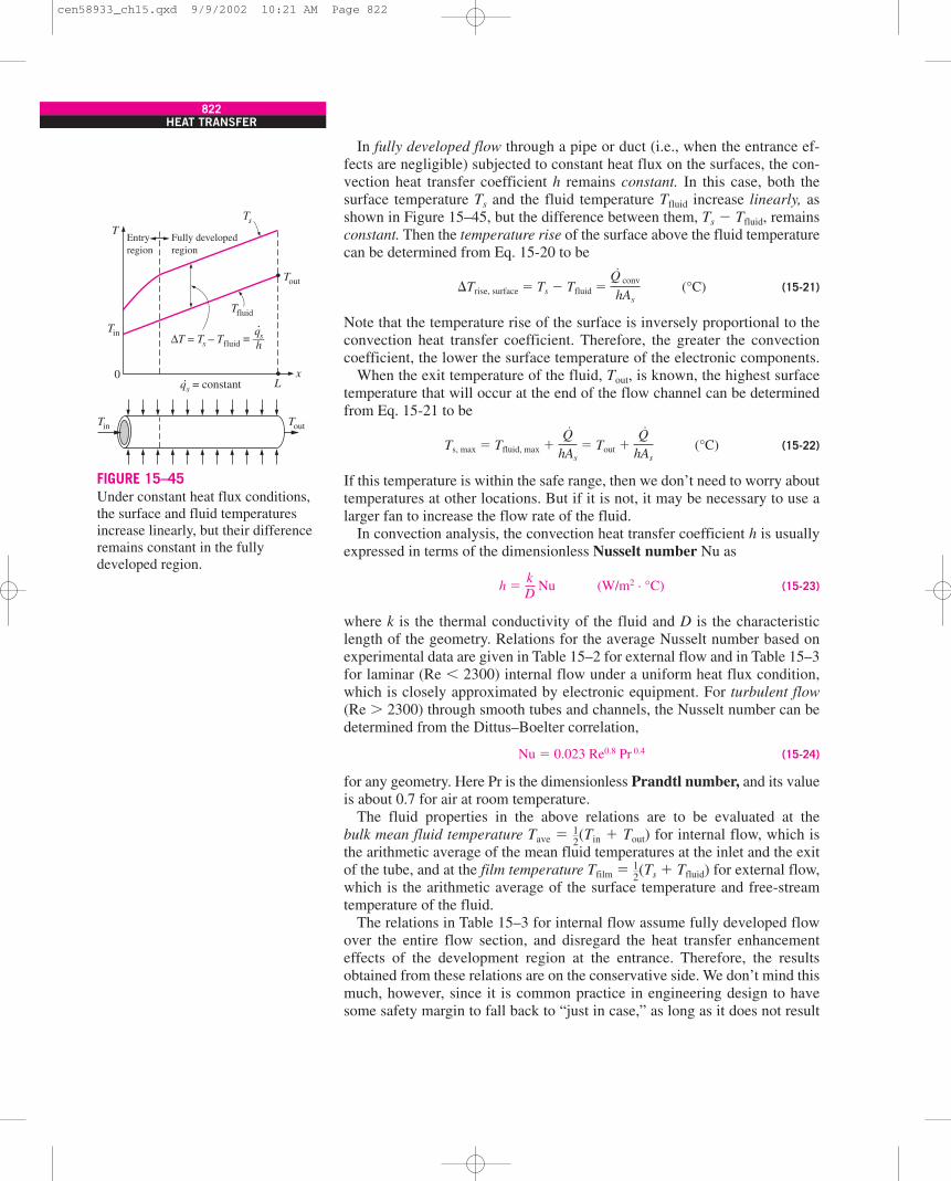
In fully developed flow through a pipe or duct (i.e., when the entrance ef-fects are negligible) subjected to constant heat flux on the surfaces, the con-vection heat transfer coefficient h remains constant. In this case, both thesurface temperature Ts and the fluid temperature Tfluid increase linearly, asshown in Figure 15–45, but the difference between them, Ts � Tfluid, remainsconstant. Then the temperature rise of the surface above the fluid temperaturecan be determined from Eq. 15-20 to be
�Trise, surface � Ts � Tfluid � (°C) (15-21)
Note that the temperature rise of the surface is inversely proportional to theconvection heat transfer coefficient. Therefore, the greater the convectioncoefficient, the lower the surface temperature of the electronic components.
When the exit temperature of the fluid, Tout, is known, the highest surfacetemperature that will occur at the end of the flow channel can be determinedfrom Eq. 15-21 to be
Ts, max � Tfluid, max � � Tout � (°C) (15-22)
If this temperature is within the safe range, then we don’t need to worry abouttemperatures at other locations. But if it is not, it may be necessary to use alarger fan to increase the flow rate of the fluid.
In convection analysis, the convection heat transfer coefficient h is usuallyexpressed in terms of the dimensionless Nusselt number Nu as
h � Nu (W/m2 · °C) (15-23)
where k is the thermal conductivity of the fluid and D is the characteristiclength of the geometry. Relations for the average Nusselt number based onexperimental data are given in Table 15–2 for external flow and in Table 15–3for laminar (Re � 2300) internal flow under a uniform heat flux condition,which is closely approximated by electronic equipment. For turbulent flow(Re � 2300) through smooth tubes and channels, the Nusselt number can bedetermined from the Dittus–Boelter correlation,
Nu � 0.023 Re0.8 Pr 0.4 (15-24)
for any geometry. Here Pr is the dimensionless Prandtl number, and its valueis about 0.7 for air at room temperature.
The fluid properties in the above relations are to be evaluated at thebulk mean fluid temperature Tave � (Tin � Tout) for internal flow, which isthe arithmetic average of the mean fluid temperatures at the inlet and the exitof the tube, and at the film temperature Tfilm � (Ts � Tfluid) for external flow,which is the arithmetic average of the surface temperature and free-streamtemperature of the fluid.
The relations in Table 15–3 for internal flow assume fully developed flowover the entire flow section, and disregard the heat transfer enhancementeffects of the development region at the entrance. Therefore, the resultsobtained from these relations are on the conservative side. We don’t mind thismuch, however, since it is common practice in engineering design to havesome safety margin to fall back to “just in case,” as long as it does not result
12
12
kD
Q·
hAs
Q·
hAs
Q· conv
hAs
822HEAT TRANSFER
Tin
Tin
T
Tout
Tout
Ts
Tfluid
Lx
∆T = Ts – Tfluid = —qsh
.
.qs = constant
0
Entryregion
Fully developedregion
FIGURE 15–45Under constant heat flux conditions,the surface and fluid temperaturesincrease linearly, but their differenceremains constant in the fullydeveloped region.
cen58933_ch15.qxd 9/9/2002 10:21 AM Page 822
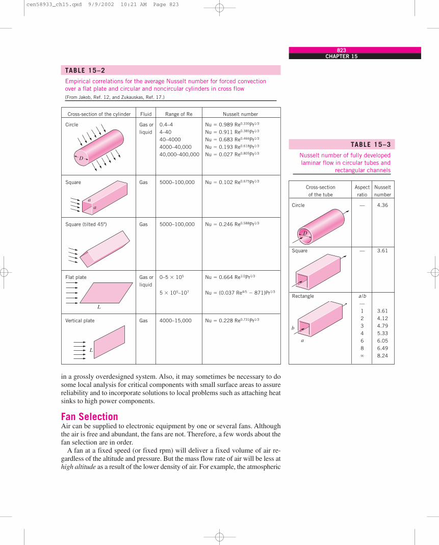
in a grossly overdesigned system. Also, it may sometimes be necessary to dosome local analysis for critical components with small surface areas to assurereliability and to incorporate solutions to local problems such as attaching heatsinks to high power components.
Fan SelectionAir can be supplied to electronic equipment by one or several fans. Althoughthe air is free and abundant, the fans are not. Therefore, a few words about thefan selection are in order.
A fan at a fixed speed (or fixed rpm) will deliver a fixed volume of air re-gardless of the altitude and pressure. But the mass flow rate of air will be less athigh altitude as a result of the lower density of air. For example, the atmospheric
CHAPTER 15823
TABLE 15–2
Empirical correlations for the average Nusselt number for forced convectionover a flat plate and circular and noncircular cylinders in cross flow(From Jakob, Ref. 12, and Zukauskas, Ref. 17.)
TABLE 15–3
Nusselt number of fully developedlaminar flow in circular tubes and
rectangular channels
Cross-section Aspect Nusseltof the tube ratio number
Circle — 4.36
Square — 3.61
Rectangle a /b—1 3.612 4.123 4.794 5.336 6.058 6.49� 8.24
D
Cross-section of the cylinder Fluid Range of Re Nusselt number
Circle Gas or 0.4–4 Nu � 0.989 Re0.330Pr1/3
liquid 4–40 Nu � 0.911 Re0.385Pr1/3
40–4000 Nu � 0.683 Re0.466Pr1/3
4000–40,000 Nu � 0.193 Re0.618Pr1/3
40,000–400,000 Nu � 0.027 Re0.805Pr1/3
Square Gas 5000–100,000 Nu � 0.102 Re0.675Pr1/3
Square (tilted 45º) Gas 5000–100,000 Nu � 0.246 Re0.588Pr1/3
Flat plate Gas or 0–5 � 105 Nu � 0.664 Re1/2Pr1/3
liquid
5 � 105–107 Nu � (0.037 Re4/5 � 871)Pr1/3
Vertical plate Gas 4000–15,000 Nu � 0.228 Re0.731Pr1/3
L
L
aa
D
b
a
cen58933_ch15.qxd 9/9/2002 10:21 AM Page 823
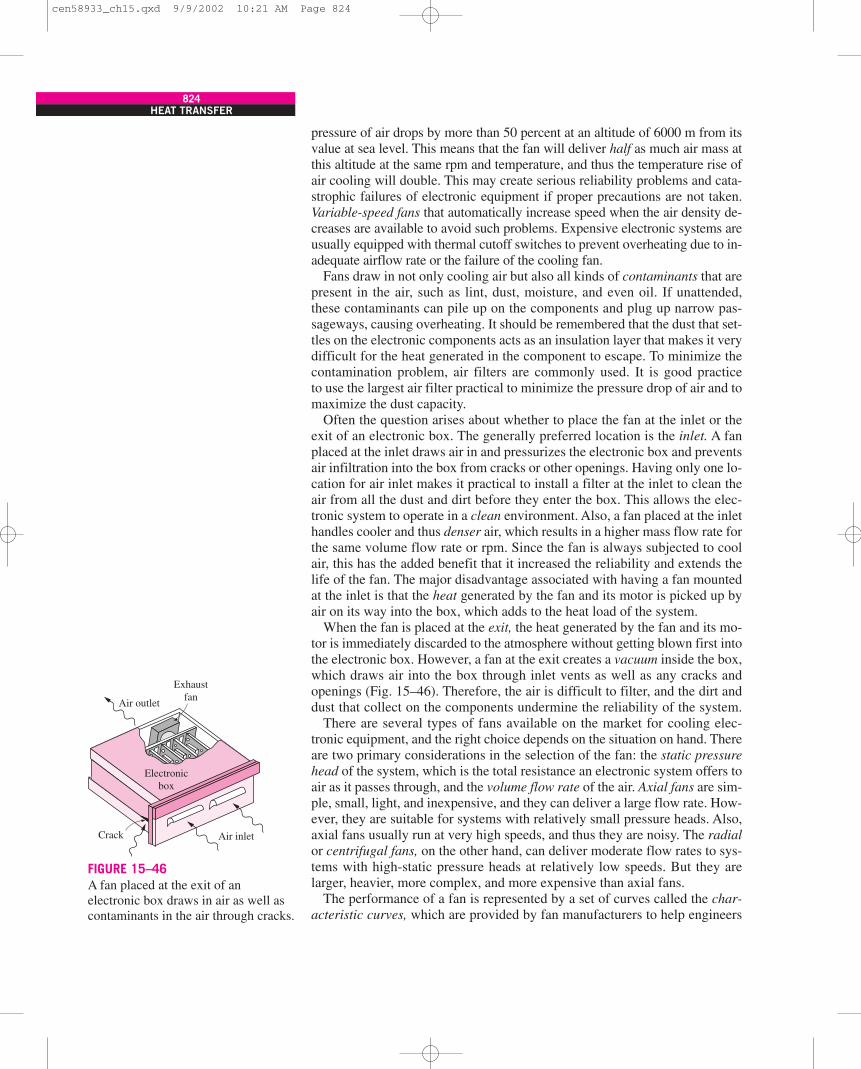
pressure of air drops by more than 50 percent at an altitude of 6000 m from itsvalue at sea level. This means that the fan will deliver half as much air mass atthis altitude at the same rpm and temperature, and thus the temperature rise ofair cooling will double. This may create serious reliability problems and cata-strophic failures of electronic equipment if proper precautions are not taken.Variable-speed fans that automatically increase speed when the air density de-creases are available to avoid such problems. Expensive electronic systems areusually equipped with thermal cutoff switches to prevent overheating due to in-adequate airflow rate or the failure of the cooling fan.
Fans draw in not only cooling air but also all kinds of contaminants that arepresent in the air, such as lint, dust, moisture, and even oil. If unattended,these contaminants can pile up on the components and plug up narrow pas-sageways, causing overheating. It should be remembered that the dust that set-tles on the electronic components acts as an insulation layer that makes it verydifficult for the heat generated in the component to escape. To minimize thecontamination problem, air filters are commonly used. It is good practiceto use the largest air filter practical to minimize the pressure drop of air and tomaximize the dust capacity.
Often the question arises about whether to place the fan at the inlet or theexit of an electronic box. The generally preferred location is the inlet. A fanplaced at the inlet draws air in and pressurizes the electronic box and preventsair infiltration into the box from cracks or other openings. Having only one lo-cation for air inlet makes it practical to install a filter at the inlet to clean theair from all the dust and dirt before they enter the box. This allows the elec-tronic system to operate in a clean environment. Also, a fan placed at the inlethandles cooler and thus denser air, which results in a higher mass flow rate forthe same volume flow rate or rpm. Since the fan is always subjected to coolair, this has the added benefit that it increased the reliability and extends thelife of the fan. The major disadvantage associated with having a fan mountedat the inlet is that the heat generated by the fan and its motor is picked up byair on its way into the box, which adds to the heat load of the system.
When the fan is placed at the exit, the heat generated by the fan and its mo-tor is immediately discarded to the atmosphere without getting blown first intothe electronic box. However, a fan at the exit creates a vacuum inside the box,which draws air into the box through inlet vents as well as any cracks andopenings (Fig. 15–46). Therefore, the air is difficult to filter, and the dirt anddust that collect on the components undermine the reliability of the system.
There are several types of fans available on the market for cooling elec-tronic equipment, and the right choice depends on the situation on hand. Thereare two primary considerations in the selection of the fan: the static pressurehead of the system, which is the total resistance an electronic system offers toair as it passes through, and the volume flow rate of the air. Axial fans are sim-ple, small, light, and inexpensive, and they can deliver a large flow rate. How-ever, they are suitable for systems with relatively small pressure heads. Also,axial fans usually run at very high speeds, and thus they are noisy. The radialor centrifugal fans, on the other hand, can deliver moderate flow rates to sys-tems with high-static pressure heads at relatively low speeds. But they arelarger, heavier, more complex, and more expensive than axial fans.
The performance of a fan is represented by a set of curves called the char-acteristic curves, which are provided by fan manufacturers to help engineers
824HEAT TRANSFER
Electronicbox
Air outlet
Exhaustfan
Air inletCrack
FIGURE 15–46A fan placed at the exit of anelectronic box draws in air as well ascontaminants in the air through cracks.
cen58933_ch15.qxd 9/9/2002 10:21 AM Page 824
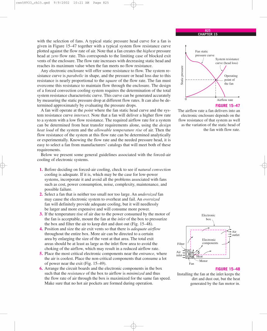
with the selection of fans. A typical static pressure head curve for a fan isgiven in Figure 15–47 together with a typical system flow resistance curveplotted against the flow rate of air. Note that a fan creates the highest pressurehead at zero flow rate. This corresponds to the limiting case of blocked exitvents of the enclosure. The flow rate increases with decreasing static head andreaches its maximum value when the fan meets no flow resistance.
Any electronic enclosure will offer some resistance to flow. The system re-sistance curve is parabolic in shape, and the pressure or head loss due to thisresistance is nearly proportional to the square of the flow rate. The fan mustovercome this resistance to maintain flow through the enclosure. The designof a forced convection cooling system requires the determination of the totalsystem resistance characteristic curve. This curve can be generated accuratelyby measuring the static pressure drop at different flow rates. It can also be de-termined approximately by evaluating the pressure drops.
A fan will operate at the point where the fan static head curve and the sys-tem resistance curve intersect. Note that a fan will deliver a higher flow rateto a system with a low flow resistance. The required airflow rate for a systemcan be determined from heat transfer requirements alone, using the designheat load of the system and the allowable temperature rise of air. Then theflow resistance of the system at this flow rate can be determined analyticallyor experimentally. Knowing the flow rate and the needed pressure head, it iseasy to select a fan from manufacturers’ catalogs that will meet both of theserequirements.
Below we present some general guidelines associated with the forced-aircooling of electronic systems.
1. Before deciding on forced-air cooling, check to see if natural convectioncooling is adequate. If it is, which may be the case for low-powersystems, incorporate it and avoid all the problems associated with fanssuch as cost, power consumption, noise, complexity, maintenance, andpossible failure.
2. Select a fan that is neither too small nor too large. An undersized fanmay cause the electronic system to overheat and fail. An oversizedfan will definitely provide adequate cooling, but it will needlesslybe larger and more expensive and will consume more power.
3. If the temperature rise of air due to the power consumed by the motor ofthe fan is acceptable, mount the fan at the inlet of the box to pressurizethe box and filter the air to keep dirt and dust out (Fig. 15–48).
4. Position and size the air exit vents so that there is adequate airflowthroughout the entire box. More air can be directed to a certainarea by enlarging the size of the vent at that area. The total exitareas should be at least as large as the inlet flow area to avoid thechoking of the airflow, which may result in a reduced airflow rate.
5. Place the most critical electronic components near the entrance, wherethe air is coolest. Place the non-critical components that consume a lotof power near the exit (Fig. 15–49).
6. Arrange the circuit boards and the electronic components in the boxsuch that the resistance of the box to airflow is minimized and thusthe flow rate of air through the box is maximized for the same fan speed.Make sure that no hot air pockets are formed during operation.
CHAPTER 15825
Fan staticpressure curve
System resistancecurve (head loss)
Operatingpoint ofthe fanSt
atic
pre
ssur
e
0 Airflow rate
FIGURE 15–47The airflow rate a fan delivers into an
electronic enclosure depends on theflow resistance of that system as well
as the variation of the static head ofthe fan with flow rate.
Filter
Airoutlet
Airinlet
Fan
Electroniccomponents
Electronicbox
MotorHeat
FIGURE 15–48Installing the fan at the inlet keeps the
dirt and dust out, but the heatgenerated by the fan motor in.
cen58933_ch15.qxd 9/9/2002 10:21 AM Page 825
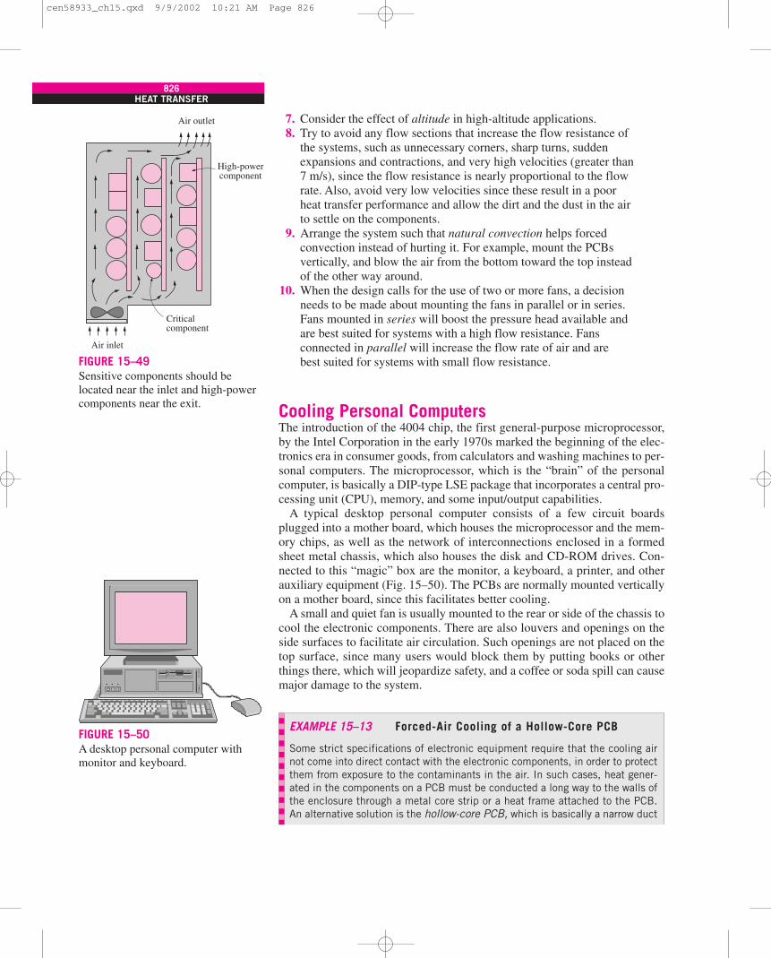
7. Consider the effect of altitude in high-altitude applications.8. Try to avoid any flow sections that increase the flow resistance of
the systems, such as unnecessary corners, sharp turns, suddenexpansions and contractions, and very high velocities (greater than7 m/s), since the flow resistance is nearly proportional to the flowrate. Also, avoid very low velocities since these result in a poorheat transfer performance and allow the dirt and the dust in the airto settle on the components.
9. Arrange the system such that natural convection helps forcedconvection instead of hurting it. For example, mount the PCBsvertically, and blow the air from the bottom toward the top insteadof the other way around.
10. When the design calls for the use of two or more fans, a decisionneeds to be made about mounting the fans in parallel or in series.Fans mounted in series will boost the pressure head available andare best suited for systems with a high flow resistance. Fansconnected in parallel will increase the flow rate of air and arebest suited for systems with small flow resistance.
Cooling Personal ComputersThe introduction of the 4004 chip, the first general-purpose microprocessor,by the Intel Corporation in the early 1970s marked the beginning of the elec-tronics era in consumer goods, from calculators and washing machines to per-sonal computers. The microprocessor, which is the “brain” of the personalcomputer, is basically a DIP-type LSE package that incorporates a central pro-cessing unit (CPU), memory, and some input/output capabilities.
A typical desktop personal computer consists of a few circuit boardsplugged into a mother board, which houses the microprocessor and the mem-ory chips, as well as the network of interconnections enclosed in a formedsheet metal chassis, which also houses the disk and CD-ROM drives. Con-nected to this “magic” box are the monitor, a keyboard, a printer, and otherauxiliary equipment (Fig. 15–50). The PCBs are normally mounted verticallyon a mother board, since this facilitates better cooling.
A small and quiet fan is usually mounted to the rear or side of the chassis tocool the electronic components. There are also louvers and openings on theside surfaces to facilitate air circulation. Such openings are not placed on thetop surface, since many users would block them by putting books or otherthings there, which will jeopardize safety, and a coffee or soda spill can causemajor damage to the system.
826HEAT TRANSFER
Air inlet
Criticalcomponent
Air outlet
High-powercomponent
FIGURE 15–49Sensitive components should belocated near the inlet and high-powercomponents near the exit.
EXAMPLE 15–13 Forced-Air Cooling of a Hollow-Core PCB
Some strict specifications of electronic equipment require that the cooling airnot come into direct contact with the electronic components, in order to protectthem from exposure to the contaminants in the air. In such cases, heat gener-ated in the components on a PCB must be conducted a long way to the walls ofthe enclosure through a metal core strip or a heat frame attached to the PCB.An alternative solution is the hollow-core PCB, which is basically a narrow duct
FIGURE 15–50A desktop personal computer withmonitor and keyboard.
cen58933_ch15.qxd 9/9/2002 10:21 AM Page 826
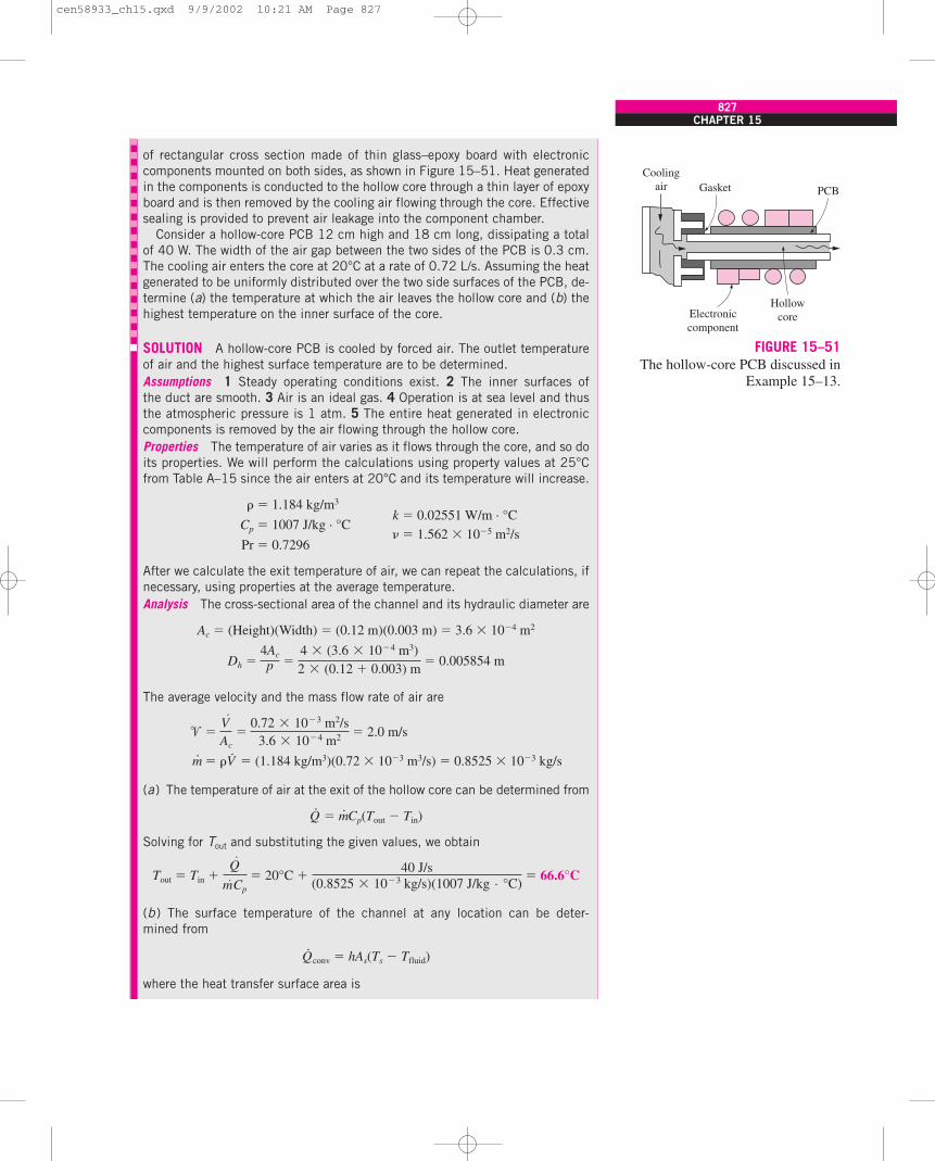
CHAPTER 15827
of rectangular cross section made of thin glass–epoxy board with electroniccomponents mounted on both sides, as shown in Figure 15–51. Heat generatedin the components is conducted to the hollow core through a thin layer of epoxyboard and is then removed by the cooling air flowing through the core. Effectivesealing is provided to prevent air leakage into the component chamber.
Consider a hollow-core PCB 12 cm high and 18 cm long, dissipating a totalof 40 W. The width of the air gap between the two sides of the PCB is 0.3 cm.The cooling air enters the core at 20°C at a rate of 0.72 L/s. Assuming the heatgenerated to be uniformly distributed over the two side surfaces of the PCB, de-termine (a) the temperature at which the air leaves the hollow core and (b) thehighest temperature on the inner surface of the core.
SOLUTION A hollow-core PCB is cooled by forced air. The outlet temperatureof air and the highest surface temperature are to be determined.Assumptions 1 Steady operating conditions exist. 2 The inner surfaces ofthe duct are smooth. 3 Air is an ideal gas. 4 Operation is at sea level and thusthe atmospheric pressure is 1 atm. 5 The entire heat generated in electroniccomponents is removed by the air flowing through the hollow core.Properties The temperature of air varies as it flows through the core, and so doits properties. We will perform the calculations using property values at 25°Cfrom Table A–15 since the air enters at 20°C and its temperature will increase.
� � 1.184 kg/m3
k � 0.02551 W/m · °CCp � 1007 J/kg · °C
Pr � 0.7296 � 1.562 � 10�5 m2/s
After we calculate the exit temperature of air, we can repeat the calculations, ifnecessary, using properties at the average temperature.Analysis The cross-sectional area of the channel and its hydraulic diameter are
Ac � (Height)(Width) � (0.12 m)(0.003 m) � 3.6 � 10�4 m2
Dh � � 0.005854 m
The average velocity and the mass flow rate of air are
� � � 2.0 m/s
m· � �V·
� (1.184 kg/m3)(0.72 � 10�3 m3/s) � 0.8525 � 10�3 kg/s
(a ) The temperature of air at the exit of the hollow core can be determined from
Q·
� m· Cp(Tout � Tin)
Solving for Tout and substituting the given values, we obtain
Tout � Tin � � 20°C � � 66.6°C
(b ) The surface temperature of the channel at any location can be deter-mined from
Q·
conv � hAs(Ts � Tfluid)
where the heat transfer surface area is
40 J/s(0.8525 � 10�3 kg/s)(1007 J/kg · °C)
Q·
m·Cp
V·
Ac�
0.72 � 10�3 m2/s3.6 � 10�4 m2
4Ac
p �4 � (3.6 � 10�4 m3)2 � (0.12 � 0.003) m
Coolingair Gasket
HollowcoreElectronic
component
PCB
FIGURE 15–51The hollow-core PCB discussed in
Example 15–13.
cen58933_ch15.qxd 9/9/2002 10:21 AM Page 827
828HEAT TRANSFER
As � 2Aside � 2(Height)(Length) � 2(0.12 m)(0.18 m) � 0.0432 m2
To determine the convection heat transfer coefficient, we first need to calculatethe Reynolds number:
Re � � 750 � 2300
Therefore, the flow is laminar, and, assuming fully developed flow, the Nusseltnumber for the airflow in this rectangular cross section corresponding to theaspect ratio a/b � (12 cm)/(0.3 cm) � 40 � � is determined from Table 15–3to be
Nu � 8.24
and thus
h � (8.24) � 35.9 W/m2 · °C
Then the surface temperature of the hollow core near the exit becomes
Ts, max � Tout � � 66.6°C � � 92.4°C
Discussion Note that the temperature difference between the surface and theair at the exit of the hollow core is 25.8°C. This temperature difference betweenthe air and the surface remains at that value throughout the core, since the heatgenerated on the side surfaces is uniform and the convection heat transfer co-efficient is constant. Therefore, the surface temperature of the core at the inletwill be 20°C � 25.8°C � 45.8°C. In reality, however, this temperature will besomewhat lower because of the entrance effects, which affect heat transfer fa-vorably. The fully developed flow assumption gives somewhat conservative re-sults but is commonly used in practice because it provides considerablesimplification in calculations.
40 W(35.9 W/m2 · °C)(0.0432 m2)
Q·
hAs
kDh
Nu �0.02551 W/m · °C
0.005854 m
�Dh
�(2 m/s)(0.005854 m)
1.562 � 10�5 m2/s
EXAMPLE 15–14 Forced-Air Cooling of a Transistor Mountedon a PCB
A TO 71 transistor with a height of 0.53 cm and a diameter of 0.44 cm ismounted on a circuit board, as shown in Figure 15–52. The transistor is cooledby air flowing over it at a velocity of 90 m/min. If the air temperature is 65°Cand the transistor case temperature is not to exceed 95°C, determine theamount of power this transistor can dissipate safely.
SOLUTION A transistor mounted on a circuit board is cooled by air flowingover it. The power dissipated when its case temperature is 90°C is to be deter-mined.Assumptions 1 Steady operating conditions exist. 2 Air is an ideal gas. 3 Oper-ation is at sea level and thus the atmospheric pressure is 1 atm.Properties The properties of air at 1 atm pressure and the film temperature ofTf �� (Ts � Tfluid)/2 � (95 � 65)/2 � 80°C are
TO 71transistor
0.53 cm
Air flow� = 90 m/min
65°C
0.44 cm
PCB
FIGURE 15–52Schematic for Example 15–14.
cen58933_ch15.qxd 9/9/2002 10:21 AM Page 828
CHAPTER 15829
� � 0.9994 kg/m3
k � 0.02953 W/m · °CCp � 1008 J/kg · °C
Pr � 0.7154 � 2.097 � 10�5 m2/s
Analysis The transistor is cooled by forced convection through its cylindricalsurface as well as its flat top and bottom surfaces. The characteristic length forflow over a cylinder is the diameter D � 0.0044 m. Then the Reynolds numberbecomes
Re � � 315
which falls into the range 40 to 4000. Using the corresponding relation fromTable 15–2 for the Nusselt number, we obtain
Nu � 0.683 Re0.466 Pr1/3 � 0.683(315)0.466(0.7154)1/ 3 � 8.91
and
h � (8.91) � 59.8 W/m2 · °C
Also,
Acyl � DL � (0.0044 m)(0.0053 m) � 0.7326 � 10�4 m2
Then the rate of heat transfer from the cylindrical surface becomes
Q·
cyl � hAcyl(Ts � Tfluid)
� (59.8 W/m2 · °C)(0.7326 � 10�4 m2)(95 � 65)°C � 0.131 W
We now repeat the calculations for the top and bottom surfaces of the transis-tor, which can be treated as flat plates of length L � 0.0044 m in the flow di-rection (which is the diameter), and, using the proper relation from Table 15–2,
Re � � 315
Nu � 0.664 Re1/2 Pr1/3 � 0.664(315)1/2(0.7154)1/3 � 10.5
and
h � (10.5) � 70.7 W/m2 · °C
Also,
Aflat � Atop � Abottom � 2 � D 2 � 2 � (0.0044 m)2 � 0.3041 � 10�4 m2
Q·
flat � hAflat(Ts � Tfluid) � (70.7 W/m2 · °C)(0.3041 � 10�4 m2)(95 � 65)°C
� 0.065 W
Therefore, the total rate of heat that can be dissipated from all surfaces of thetransistor is
Q·
total � Q·
cyl � Q·
flat � (0.131 � 0.065) W � 0.196 W
which seems to be low. This value can be increased considerably by attachinga heat sink to the transistor to enhance the heat transfer surface area and thusheat transfer, or by increasing the air velocity, which will increase the heattransfer coefficient.
14
14
kD
Nu �0.02953 W/m · °C
0.0044 m
�L �
( 9060
m/s)(0.0044 m)
2.097 � 10�5 m2/s
kD
Nu �0.02953 W/m · °C
0.0044 m
�D �
( 9060
m/s)(0.0044 m)
2.097 � 10�5 m2/s
cen58933_ch15.qxd 9/9/2002 10:21 AM Page 829
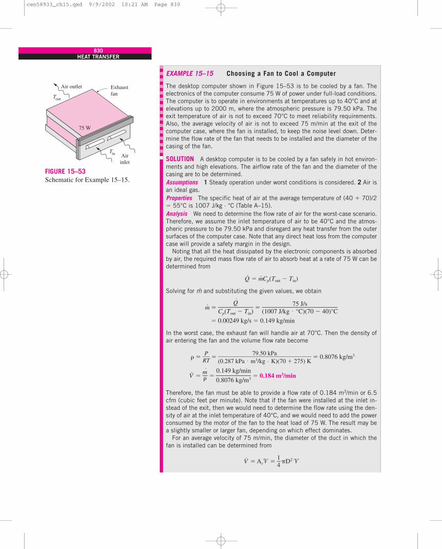
830HEAT TRANSFER
EXAMPLE 15–15 Choosing a Fan to Cool a Computer
The desktop computer shown in Figure 15–53 is to be cooled by a fan. Theelectronics of the computer consume 75 W of power under full-load conditions.The computer is to operate in environments at temperatures up to 40°C and atelevations up to 2000 m, where the atmospheric pressure is 79.50 kPa. Theexit temperature of air is not to exceed 70°C to meet reliability requirements.Also, the average velocity of air is not to exceed 75 m/min at the exit of thecomputer case, where the fan is installed, to keep the noise level down. Deter-mine the flow rate of the fan that needs to be installed and the diameter of thecasing of the fan.
SOLUTION A desktop computer is to be cooled by a fan safely in hot environ-ments and high elevations. The airflow rate of the fan and the diameter of thecasing are to be determined.Assumptions 1 Steady operation under worst conditions is considered. 2 Air isan ideal gas.Properties The specific heat of air at the average temperature of (40 � 70)/2� 55°C is 1007 J/kg · °C (Table A–15).Analysis We need to determine the flow rate of air for the worst-case scenario.Therefore, we assume the inlet temperature of air to be 40°C and the atmos-pheric pressure to be 79.50 kPa and disregard any heat transfer from the outersurfaces of the computer case. Note that any direct heat loss from the computercase will provide a safety margin in the design.
Noting that all the heat dissipated by the electronic components is absorbedby air, the required mass flow rate of air to absorb heat at a rate of 75 W can bedetermined from
Q·
� m· Cp(Tout � Tin)
Solving for m· and substituting the given values, we obtain
m· �
� 0.00249 kg/s � 0.149 kg/min
In the worst case, the exhaust fan will handle air at 70°C. Then the density ofair entering the fan and the volume flow rate become
� � � 0.8076 kg/m3
V·
� � 0.184 m3/min
Therefore, the fan must be able to provide a flow rate of 0.184 m3/min or 6.5cfm (cubic feet per minute). Note that if the fan were installed at the inlet in-stead of the exit, then we would need to determine the flow rate using the den-sity of air at the inlet temperature of 40°C, and we would need to add the powerconsumed by the motor of the fan to the heat load of 75 W. The result may bea slightly smaller or larger fan, depending on which effect dominates.
For an average velocity of 75 m/min, the diameter of the duct in which thefan is installed can be determined from
V·
� Ac� � D2 �14
m·� �
0.149 kg/min
0.8076 kg/m3
PRT
�79.50 kPa
(0.287 kPa · m3/kg · K)(70 � 275) K
Q·
Cp(Tout � Tin)�
75 J/s(1007 J/kg · °C)(70 � 40)°C
Air outlet Exhaustfan
Airinlet
75 W
Tin
Tout
FIGURE 15–53Schematic for Example 15–15.
cen58933_ch15.qxd 9/9/2002 10:21 AM Page 830
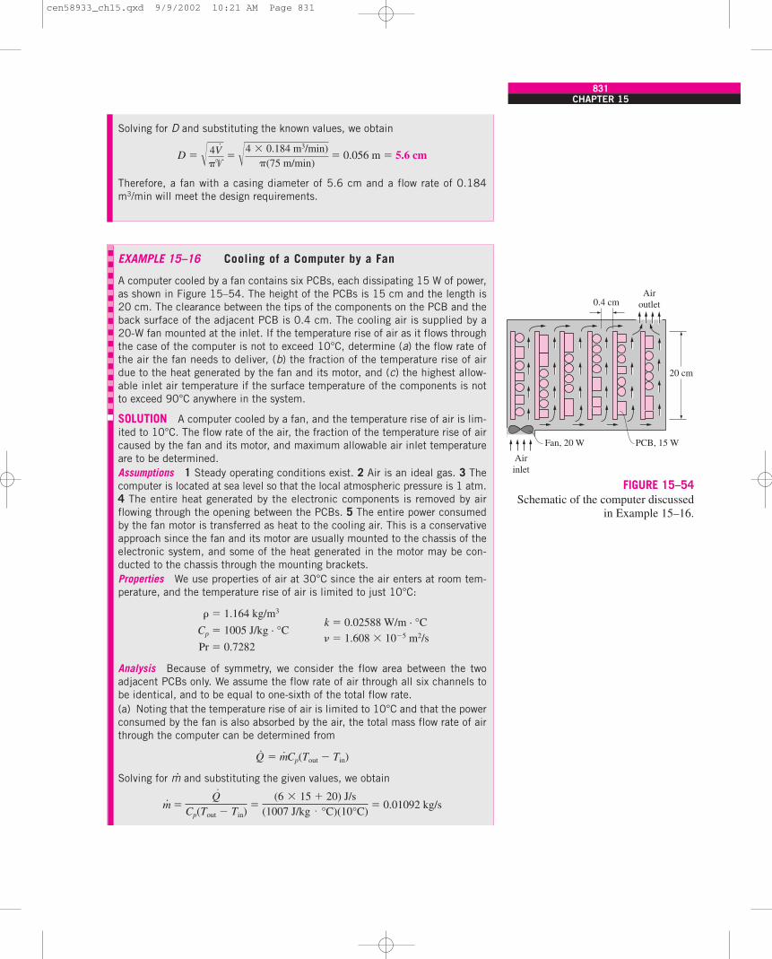
CHAPTER 15831
Solving for D and substituting the known values, we obtain
D � � 0.056 m � 5.6 cm
Therefore, a fan with a casing diameter of 5.6 cm and a flow rate of 0.184m3/min will meet the design requirements.
� 4V·
�� �4 � 0.184 m3/min)
(75 m/min)
EXAMPLE 15–16 Cooling of a Computer by a Fan
A computer cooled by a fan contains six PCBs, each dissipating 15 W of power,as shown in Figure 15–54. The height of the PCBs is 15 cm and the length is20 cm. The clearance between the tips of the components on the PCB and theback surface of the adjacent PCB is 0.4 cm. The cooling air is supplied by a20-W fan mounted at the inlet. If the temperature rise of air as it flows throughthe case of the computer is not to exceed 10°C, determine (a) the flow rate ofthe air the fan needs to deliver, (b) the fraction of the temperature rise of airdue to the heat generated by the fan and its motor, and (c) the highest allow-able inlet air temperature if the surface temperature of the components is notto exceed 90°C anywhere in the system.
SOLUTION A computer cooled by a fan, and the temperature rise of air is lim-ited to 10°C. The flow rate of the air, the fraction of the temperature rise of aircaused by the fan and its motor, and maximum allowable air inlet temperatureare to be determined.Assumptions 1 Steady operating conditions exist. 2 Air is an ideal gas. 3 Thecomputer is located at sea level so that the local atmospheric pressure is 1 atm.4 The entire heat generated by the electronic components is removed by airflowing through the opening between the PCBs. 5 The entire power consumedby the fan motor is transferred as heat to the cooling air. This is a conservativeapproach since the fan and its motor are usually mounted to the chassis of theelectronic system, and some of the heat generated in the motor may be con-ducted to the chassis through the mounting brackets.Properties We use properties of air at 30°C since the air enters at room tem-perature, and the temperature rise of air is limited to just 10°C:
� � 1.164 kg/m3
k � 0.02588 W/m · °CCp � 1005 J/kg · °C
Pr � 0.7282 � 1.608 � 10�5 m2/s
Analysis Because of symmetry, we consider the flow area between the twoadjacent PCBs only. We assume the flow rate of air through all six channels tobe identical, and to be equal to one-sixth of the total flow rate.(a) Noting that the temperature rise of air is limited to 10°C and that the powerconsumed by the fan is also absorbed by the air, the total mass flow rate of airthrough the computer can be determined from
Q·
� m· Cp(Tout � Tin)
Solving for m· and substituting the given values, we obtain
m· � � 0.01092 kg/sQ·
Cp(Tout � Tin)�
(6 � 15 � 20) J/s(1007 J/kg · °C)(10°C)
Fan, 20 W PCB, 15 W
Airinlet
20 cm
0.4 cmAir
outlet
FIGURE 15–54Schematic of the computer discussed
in Example 15–16.
cen58933_ch15.qxd 9/9/2002 10:21 AM Page 831
832HEAT TRANSFER
Then the volume flow rate of air and the air velocity become
V·
� � 0.009381 m3/s � 0.563 m3/min
� � � 2.606 m/s
Therefore, the fan needs to supply air at a rate of 0.563 m3/min, or about20 cfm.
(b) The temperature rise of air due to the power consumed by the fan motor canbe determined by assuming the entire 20 W of power consumed by the motor tobe transferred to air as heat:
�Tair, rise � � 1.8°C
Therefore, 18 percent of the temperature rise of air is due to the heat generatedby the fan motor. Note that the fraction of the power consumed by the fan isalso 18 percent of the total, as expected.
(c) The surface temperature of the channel at any location can be deter-mined from
q· conv � Q·
conv /As � h(Ts � Tfluid)
where the heat transfer surface area is
As � Aside � (Height)(Length) � (0.15 m)(0.20 m) � 0.03 m2
To determine the convection heat transfer coefficient, we first need to calculatethe Reynolds number. The cross-sectional area of the channel and its hydraulicdiameter are
Ac � (Height)(Width) � (0.15 m)(0.004 m) � 6 � 10�4 m2
Dh � � 0.007792 m
Then the Reynolds number becomes
Re � � 1263 � 2300
Therefore, the flow is laminar, and, assuming fully developed flow, the Nusseltnumber for the airflow in this rectangular cross-section corresponding to the as-pect ratio a/b � (15 cm)/(0.4 cm) � 37.5 � � is determined from Table 15–3to be
Nu � 8.24
and thus
h � (8.24) � 27.4 W/m2 · °C
Disregarding the entrance effects, the temperature difference between thesurface of the PCB and the air anywhere along the channel is determined to be
kDh
Nu �0.02588 W/m · °C
0.007792 m
�Dh
�(2.606 m/s)(0.007792 m)
1.606 � 10�5 m2/s
4 Ac
p �4 � (6 � 10�4 m2)
2 � (0.15 � 0.004) m
Q·
fan
m· Cp�
20 J/s(0.01092 kg/s)(1007 J/kg · °C)
V·
Ac�
0.009381 m3/s6 � (6 � 10�4 m2)
m·� �
0.01092 kg/s
1.164 kg/m3
cen58933_ch15.qxd 9/9/2002 10:21 AM Page 832
15–9 LIQUID COOLINGLiquids normally have much higher thermal conductivities than gases, and thusmuch higher heat transfer coefficients associated with them. Therefore, liquidcooling is far more effective than gas cooling. However, liquid cooling comeswith its own risks and potential problems, such as leakage, corrosion, extraweight, and condensation. Therefore, liquid cooling is reserved for applicationsinvolving power densities that are too high for safe dissipation by air cooling.
Liquid cooling systems can be classified as direct cooling and indirect cool-ing systems. In direct cooling systems, the electronic components are in directcontact with the liquid, and thus the heat generated in the components is trans-ferred directly to the liquid. In indirect cooling systems, however, there is nodirect contact with the components. The heat generated in this case is firsttransferred to a medium such as a cold plate before it is carried away by the liq-uid. Liquid cooling systems are also classified as closed-loop and open-loopsystems, depending on whether the liquid is discarded or recirculated after it isheated. In open-loop systems, tap water flows through the cooling system andis discarded into a drain after it is heated. The heated liquid in closed-loop sys-tems is cooled in a heat exchanger and recirculated through the system. Closed-loop systems facilitate better temperature control while conserving water.
The electronic components in direct cooling systems are usually completelyimmersed in the liquid. The heat transfer from the components to the liquidcan be by natural or forced convection or boiling, depending on the tempera-ture levels involved and the properties of the fluids. Immersion cooling ofelectronic devices usually involves boiling and thus very high heat transfer co-efficients, as discussed in the next section. Note that only dielectric fluids canbe used in immersion or direct liquid cooling. This limitation immediately ex-cludes water from consideration as a prospective fluid in immersion cooling.
�
CHAPTER 15833
Ts � Tfluid � � 18.3°C
That is, the surface temperature of the components on the PCB will be 18.3°Chigher than the temperature of air passing by.
The highest air and component temperatures will occur at the exit. Therefore,in the limiting case, the component surface temperature at the exit will be90°C. The air temperature at the exit in this case will be
Tout, max � Ts, max � �Trise � 90°C � 18.3°C � 71.7°C
Noting that the air experiences a temperature rise of 10°C between the inletand the exit, the inlet temperature of air is
Tin, max � Tout, max � 10°C � (71.7 � 10)°C � 61.7°C
This is the highest allowable air inlet temperature if the surface temperature ofthe components is not to exceed 90°C anywhere in the system.
It should be noted that the analysis presented above is approximate since wehave made some simplifying assumptions. However, the accuracy of the resultsobtained is usually adequate for engineering purposes.
�q·
h �PCB�
(15 W)/(0.03 m2)
27.4 W/m2 · °C
cen58933_ch15.qxd 9/9/2002 10:21 AM Page 833
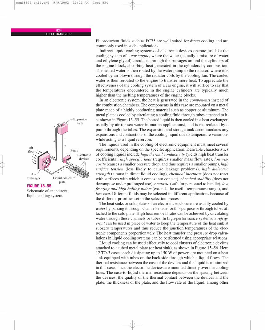
Fluorocarbon fluids such as FC75 are well suited for direct cooling and arecommonly used in such applications.
Indirect liquid cooling systems of electronic devices operate just like thecooling system of a car engine, where the water (actually a mixture of waterand ethylene glycol) circulates through the passages around the cylinders ofthe engine block, absorbing heat generated in the cylinders by combustion.The heated water is then routed by the water pump to the radiator, where it iscooled by air blown through the radiator coils by the cooling fan. The cooledwater is then rerouted to the engine to transfer more heat. To appreciate theeffectiveness of the cooling system of a car engine, it will suffice to say thatthe temperatures encountered in the engine cylinders are typically muchhigher than the melting temperatures of the engine blocks.
In an electronic system, the heat is generated in the components instead ofthe combustion chambers. The components in this case are mounted on a metalplate made of a highly conducting material such as copper or aluminum. Themetal plate is cooled by circulating a cooling fluid through tubes attached to it,as shown in Figure 15–55. The heated liquid is then cooled in a heat exchanger,usually by air (or sea water in marine applications), and is recirculated by apump through the tubes. The expansion and storage tank accommodates anyexpansions and contractions of the cooling liquid due to temperature variationswhile acting as a liquid reservoir.
The liquids used in the cooling of electronic equipment must meet severalrequirements, depending on the specific application. Desirable characteristicsof cooling liquids include high thermal conductivity (yields high heat transfercoefficients), high specific heat (requires smaller mass flow rate), low vis-cosity (causes a smaller pressure drop, and thus requires a smaller pump), highsurface tension (less likely to cause leakage problems), high dielectricstrength (a must in direct liquid cooling), chemical inertness (does not reactwith surfaces with which it comes into contact), chemical stability (does notdecompose under prolonged use), nontoxic (safe for personnel to handle), lowfreezing and high boiling points (extends the useful temperature range), andlow cost. Different fluids may be selected in different applications because ofthe different priorities set in the selection process.
The heat sinks or cold plates of an electronic enclosure are usually cooled bywater by passing it through channels made for this purpose or through tubes at-tached to the cold plate. High heat removal rates can be achieved by circulatingwater through these channels or tubes. In high-performance systems, a refrig-erant can be used in place of water to keep the temperature of the heat sink atsubzero temperatures and thus reduce the junction temperatures of the elec-tronic components proportionately. The heat transfer and pressure drop calcu-lations in liquid cooling systems can be performed using appropriate relations.
Liquid cooling can be used effectively to cool clusters of electronic devicesattached to a tubed metal plate (or heat sink), as shown in Figure 15–56. Here12 TO-3 cases, each dissipating up to 150 W of power, are mounted on a heatsink equipped with tubes on the back side through which a liquid flows. Thethermal resistance between the case of the devices and the liquid is minimizedin this case, since the electronic devices are mounted directly over the coolinglines. The case-to-liquid thermal resistance depends on the spacing betweenthe devices, the quality of the thermal contact between the devices and theplate, the thickness of the plate, and the flow rate of the liquid, among other
834HEAT TRANSFER
Electronicdevices
Liquid-cooledplate
Heatexchanger
Airflow
Expansiontank
Pump
FIGURE 15–55Schematic of an indirectliquid cooling system.
cen58933_ch15.qxd 9/9/2002 10:21 AM Page 834
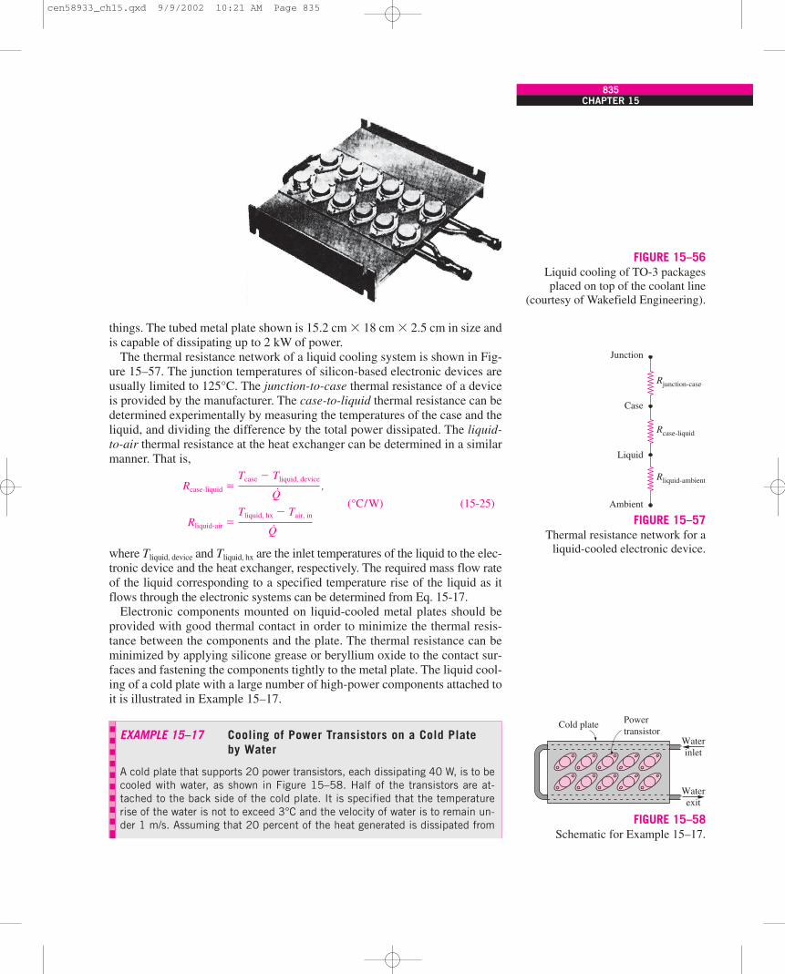
things. The tubed metal plate shown is 15.2 cm � 18 cm � 2.5 cm in size andis capable of dissipating up to 2 kW of power.
The thermal resistance network of a liquid cooling system is shown in Fig-ure 15–57. The junction temperatures of silicon-based electronic devices areusually limited to 125°C. The junction-to-case thermal resistance of a deviceis provided by the manufacturer. The case-to-liquid thermal resistance can bedetermined experimentally by measuring the temperatures of the case and theliquid, and dividing the difference by the total power dissipated. The liquid-to-air thermal resistance at the heat exchanger can be determined in a similarmanner. That is,
Rcase-liquid � ,
(°C/W) (15-25)
Rliquid-air �
where Tliquid, device and Tliquid, hx are the inlet temperatures of the liquid to the elec-tronic device and the heat exchanger, respectively. The required mass flow rateof the liquid corresponding to a specified temperature rise of the liquid as itflows through the electronic systems can be determined from Eq. 15-17.
Electronic components mounted on liquid-cooled metal plates should beprovided with good thermal contact in order to minimize the thermal resis-tance between the components and the plate. The thermal resistance can beminimized by applying silicone grease or beryllium oxide to the contact sur-faces and fastening the components tightly to the metal plate. The liquid cool-ing of a cold plate with a large number of high-power components attached toit is illustrated in Example 15–17.
Tliquid, hx � Tair, in
Q·
Tcase � Tliquid, device
Q·
CHAPTER 15835
FIGURE 15–56Liquid cooling of TO-3 packagesplaced on top of the coolant line
(courtesy of Wakefield Engineering).
Rjunction-case
Rcase-liquid
Rliquid-ambient
Junction
Case
Liquid
Ambient
FIGURE 15–57Thermal resistance network for a
liquid-cooled electronic device.
EXAMPLE 15–17 Cooling of Power Transistors on a Cold Plateby Water
A cold plate that supports 20 power transistors, each dissipating 40 W, is to becooled with water, as shown in Figure 15–58. Half of the transistors are at-tached to the back side of the cold plate. It is specified that the temperaturerise of the water is not to exceed 3°C and the velocity of water is to remain un-der 1 m/s. Assuming that 20 percent of the heat generated is dissipated from
Cold plate Powertransistor
Waterinlet
Waterexit
FIGURE 15–58Schematic for Example 15–17.
cen58933_ch15.qxd 9/9/2002 10:21 AM Page 835
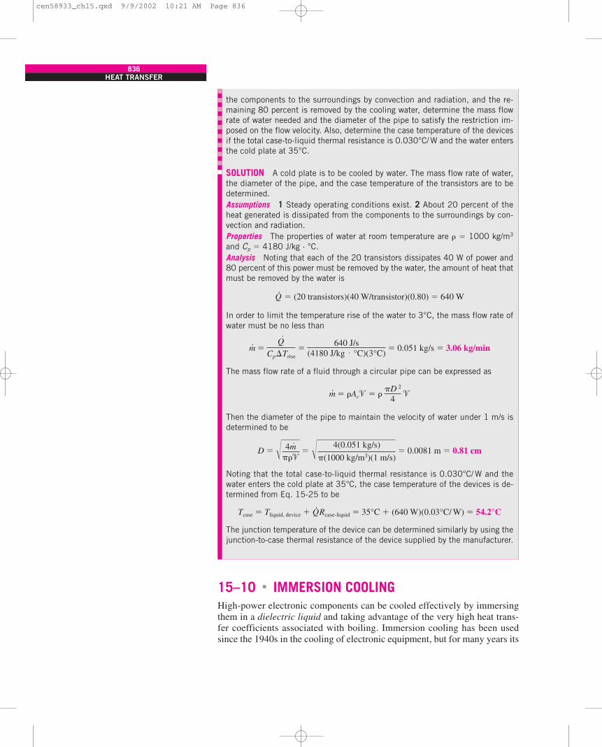
15–10 IMMERSION COOLINGHigh-power electronic components can be cooled effectively by immersingthem in a dielectric liquid and taking advantage of the very high heat trans-fer coefficients associated with boiling. Immersion cooling has been usedsince the 1940s in the cooling of electronic equipment, but for many years its
�
836HEAT TRANSFER
the components to the surroundings by convection and radiation, and the re-maining 80 percent is removed by the cooling water, determine the mass flowrate of water needed and the diameter of the pipe to satisfy the restriction im-posed on the flow velocity. Also, determine the case temperature of the devicesif the total case-to-liquid thermal resistance is 0.030°C/W and the water entersthe cold plate at 35°C.
SOLUTION A cold plate is to be cooled by water. The mass flow rate of water,the diameter of the pipe, and the case temperature of the transistors are to bedetermined.Assumptions 1 Steady operating conditions exist. 2 About 20 percent of theheat generated is dissipated from the components to the surroundings by con-vection and radiation.Properties The properties of water at room temperature are � � 1000 kg/m3
and Cp � 4180 J/kg · °C.Analysis Noting that each of the 20 transistors dissipates 40 W of power and80 percent of this power must be removed by the water, the amount of heat thatmust be removed by the water is
Q·
� (20 transistors)(40 W/transistor)(0.80) � 640 W
In order to limit the temperature rise of the water to 3°C, the mass flow rate ofwater must be no less than
m· � � 0.051 kg/s � 3.06 kg/min
The mass flow rate of a fluid through a circular pipe can be expressed as
m· � �Ac� � � �
Then the diameter of the pipe to maintain the velocity of water under 1 m/s isdetermined to be
D � � 0.0081 m � 0.81 cm
Noting that the total case-to-liquid thermal resistance is 0.030°C/ W and thewater enters the cold plate at 35°C, the case temperature of the devices is de-termined from Eq. 15-25 to be
Tcase � Tliquid, device � Q·Rcase-liquid � 35°C � (640 W)(0.03°C/ W) � 54.2°C
The junction temperature of the device can be determined similarly by using thejunction-to-case thermal resistance of the device supplied by the manufacturer.
� 4m·
��� � 4(0.051 kg/s)
(1000 kg/m3)(1 m/s)
D 2
4
Q·
Cp�Trise�
640 J/s(4180 J/kg · °C)(3°C)
cen58933_ch15.qxd 9/9/2002 10:21 AM Page 836
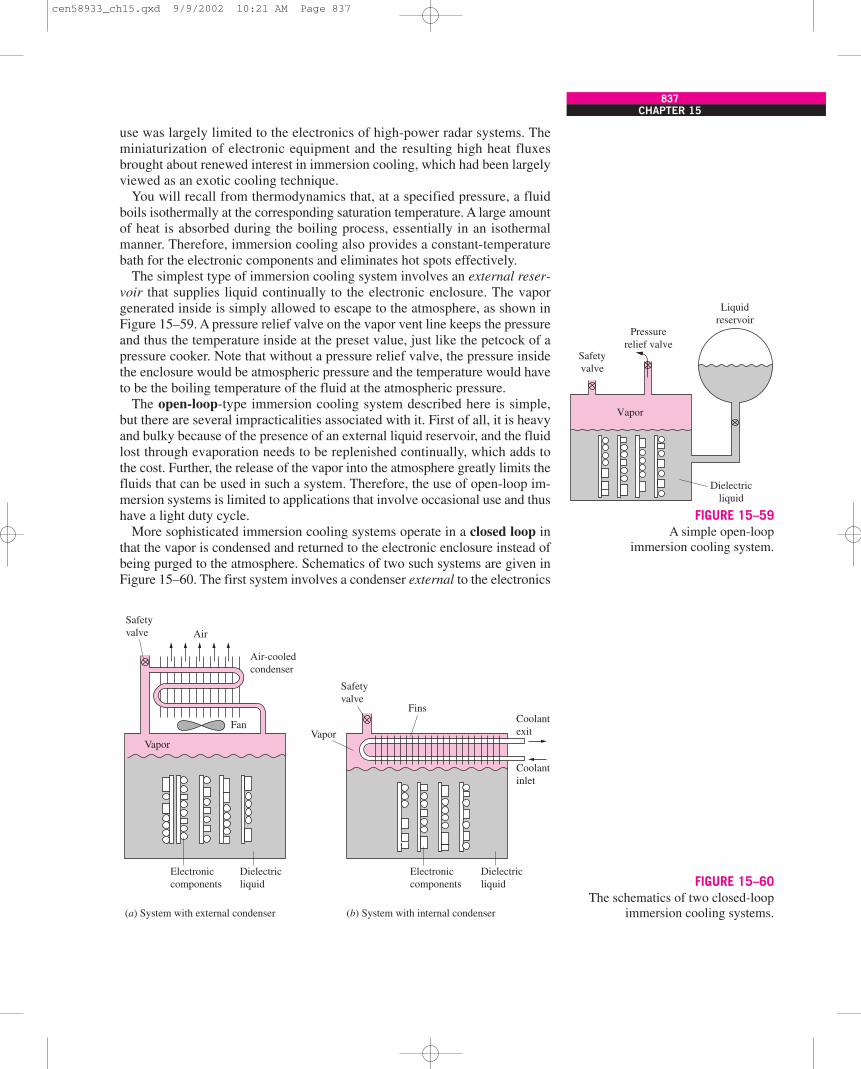
use was largely limited to the electronics of high-power radar systems. Theminiaturization of electronic equipment and the resulting high heat fluxesbrought about renewed interest in immersion cooling, which had been largelyviewed as an exotic cooling technique.
You will recall from thermodynamics that, at a specified pressure, a fluidboils isothermally at the corresponding saturation temperature. A large amountof heat is absorbed during the boiling process, essentially in an isothermalmanner. Therefore, immersion cooling also provides a constant-temperaturebath for the electronic components and eliminates hot spots effectively.
The simplest type of immersion cooling system involves an external reser-voir that supplies liquid continually to the electronic enclosure. The vaporgenerated inside is simply allowed to escape to the atmosphere, as shown inFigure 15–59. A pressure relief valve on the vapor vent line keeps the pressureand thus the temperature inside at the preset value, just like the petcock of apressure cooker. Note that without a pressure relief valve, the pressure insidethe enclosure would be atmospheric pressure and the temperature would haveto be the boiling temperature of the fluid at the atmospheric pressure.
The open-loop-type immersion cooling system described here is simple,but there are several impracticalities associated with it. First of all, it is heavyand bulky because of the presence of an external liquid reservoir, and the fluidlost through evaporation needs to be replenished continually, which adds tothe cost. Further, the release of the vapor into the atmosphere greatly limits thefluids that can be used in such a system. Therefore, the use of open-loop im-mersion systems is limited to applications that involve occasional use and thushave a light duty cycle.
More sophisticated immersion cooling systems operate in a closed loop inthat the vapor is condensed and returned to the electronic enclosure instead ofbeing purged to the atmosphere. Schematics of two such systems are given inFigure 15–60. The first system involves a condenser external to the electronics
CHAPTER 15837
Safetyvalve
Pressurerelief valve
Liquidreservoir
Vapor
Dielectricliquid
FIGURE 15–59A simple open-loop
immersion cooling system.
FIGURE 15–60The schematics of two closed-loop
immersion cooling systems.
Fan
Air
Air-cooledcondenser
Safetyvalve
Safetyvalve
VaporVapor
Fins
Electroniccomponents
Dielectricliquid
Electroniccomponents
Dielectricliquid
(a) System with external condenser (b) System with internal condenser
Coolantexit
Coolantinlet
cen58933_ch15.qxd 9/9/2002 10:21 AM Page 837

enclosure, and the vapor leaving the enclosure is cooled by a cooling fluid suchas air or water outside the enclosure. The condensate is returned to the enclo-sure for reuse. The condenser in the second system is actually submerged in theelectronic enclosure and is part of the electronic system. The cooling fluid inthis case circulates through the condenser tube, removing heat from the vapor.The vapor that condenses drips on top of the liquid in the enclosure and con-tinues to recirculate.
The performance of closed-loop immersion cooling systems is most sus-ceptible to the presence of noncondensable gases such as air in the vaporspace. An increase of 0.5 percent of air by mass in the vapor can cause thecondensation heat transfer coefficient to drop by a factor of up to 5. Therefore,the fluid used in immersion cooling systems should be degassed as much aspractical, and care should be taken during the filling process to avoid intro-ducing any air into the system.
The problems associated with the condensation process and noncondens-able gases can be avoided by submerging the condenser (actually, heat ex-changer tubes in this case) in the liquid instead of the vapor in the electronicenclosure, as shown in Figure 15–61a. The cooling fluid, such as water, cir-culating through the tubes absorbs heat from the dielectric liquid at the topportion of the enclosure and subcools it. The liquid in contact with the elec-tronic components is heated and may even be vaporized as a result of absorb-ing heat from the components. But these vapor bubbles collapse as they moveup, as a result of transferring heat to the cooler liquid with which they comein contact. This system can still remove heat at high rates from the surfacesof electronic components in an isothermal manner by utilizing the boilingprocess, but its overall capacity is limited by the rate of heat that can beremoved by the external cooling fluid in a liquid-to-liquid heat exchanger.Noting that the heat transfer coefficients associated with forced convection arefar less than those associated with condensation, this all-liquid immersioncooling system is not suitable for electronic boxes with very high power dis-sipation rates per unit volume.
A step further in the all-liquid immersion cooling systems is to remove theheat from the dielectric liquid directly from the outer surface of the electron-ics enclosure, as shown in Figure 15–61b. In this case, the dielectric liquid
838HEAT TRANSFER
FIGURE 15–61The schematics of two all-liquidimmersion cooling systems.
Dielectricliquid
Airoutlet
Airinlet
Electroniccomponents
Electroniccomponents
Dielectricliquid
Fan
Coolantinlet
Coolantexit
Expansionchamber
Pressurerelief valve
Expansionchamber Pressure
reliefvalve Fins
(a) System with internal cooling (b) System with external cooling
cen58933_ch15.qxd 9/9/2002 10:21 AM Page 838
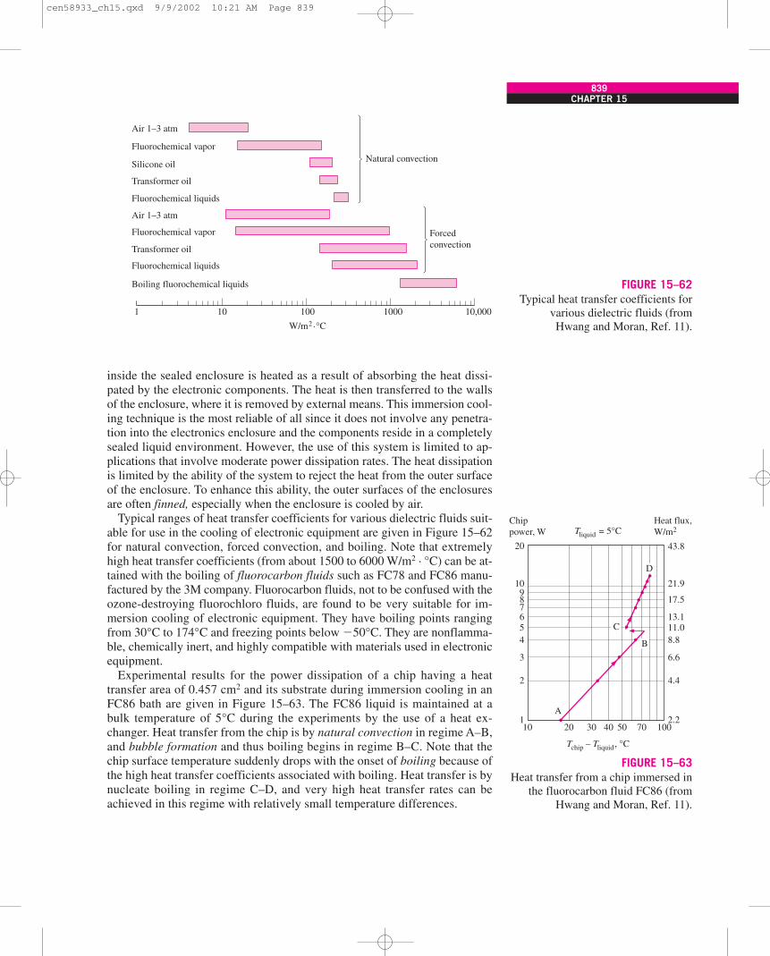
inside the sealed enclosure is heated as a result of absorbing the heat dissi-pated by the electronic components. The heat is then transferred to the wallsof the enclosure, where it is removed by external means. This immersion cool-ing technique is the most reliable of all since it does not involve any penetra-tion into the electronics enclosure and the components reside in a completelysealed liquid environment. However, the use of this system is limited to ap-plications that involve moderate power dissipation rates. The heat dissipationis limited by the ability of the system to reject the heat from the outer surfaceof the enclosure. To enhance this ability, the outer surfaces of the enclosuresare often finned, especially when the enclosure is cooled by air.
Typical ranges of heat transfer coefficients for various dielectric fluids suit-able for use in the cooling of electronic equipment are given in Figure 15–62for natural convection, forced convection, and boiling. Note that extremelyhigh heat transfer coefficients (from about 1500 to 6000 W/m2 · °C) can be at-tained with the boiling of fluorocarbon fluids such as FC78 and FC86 manu-factured by the 3M company. Fluorocarbon fluids, not to be confused with theozone-destroying fluorochloro fluids, are found to be very suitable for im-mersion cooling of electronic equipment. They have boiling points rangingfrom 30°C to 174°C and freezing points below �50°C. They are nonflamma-ble, chemically inert, and highly compatible with materials used in electronicequipment.
Experimental results for the power dissipation of a chip having a heattransfer area of 0.457 cm2 and its substrate during immersion cooling in anFC86 bath are given in Figure 15–63. The FC86 liquid is maintained at abulk temperature of 5°C during the experiments by the use of a heat ex-changer. Heat transfer from the chip is by natural convection in regime A–B,and bubble formation and thus boiling begins in regime B–C. Note that thechip surface temperature suddenly drops with the onset of boiling because ofthe high heat transfer coefficients associated with boiling. Heat transfer is bynucleate boiling in regime C–D, and very high heat transfer rates can beachieved in this regime with relatively small temperature differences.
CHAPTER 15839
FIGURE 15–62Typical heat transfer coefficients for
various dielectric fluids (fromHwang and Moran, Ref. 11).
Air 1–3 atm
Fluorochemical vapor
Silicone oil
Transformer oil
Fluorochemical liquids
Natural convection
Air 1–3 atm
Fluorochemical vapor
Transformer oil
Fluorochemical liquids
Boiling fluorochemical liquids
1 10 100
W/m2 . °C
1000 10,000
Forcedconvection
20
10987654
3
2
110 20 30
Tchip – Tliquid, °C
Tliquid = 5°C
40 50 70 100
21.9
43.8
Heat flux,W/m2
Chippower, W
17.5
13.111.08.8
6.6
4.4
2.2
C
D
B
A
FIGURE 15–63Heat transfer from a chip immersed in
the fluorocarbon fluid FC86 (fromHwang and Moran, Ref. 11).
cen58933_ch15.qxd 9/9/2002 10:21 AM Page 839
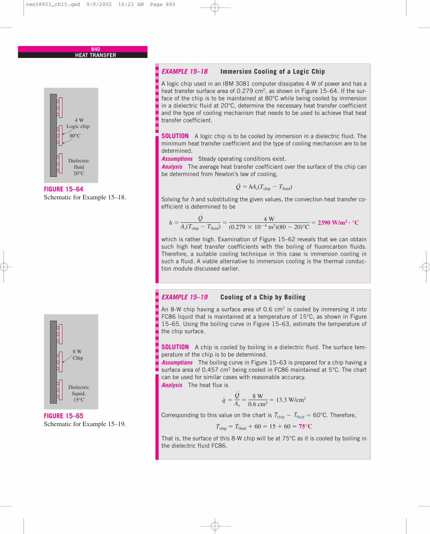
840HEAT TRANSFER
EXAMPLE 15–18 Immersion Cooling of a Logic Chip
A logic chip used in an IBM 3081 computer dissipates 4 W of power and has aheat transfer surface area of 0.279 cm2, as shown in Figure 15–64. If the sur-face of the chip is to be maintained at 80°C while being cooled by immersionin a dielectric fluid at 20°C, determine the necessary heat transfer coefficientand the type of cooling mechanism that needs to be used to achieve that heattransfer coefficient.
SOLUTION A logic chip is to be cooled by immersion in a dielectric fluid. Theminimum heat transfer coefficient and the type of cooling mechanism are to bedetermined.Assumptions Steady operating conditions exist.Analysis The average heat transfer coefficient over the surface of the chip canbe determined from Newton’s law of cooling,
Q·
� hAs(Tchip � Tfluid)
Solving for h and substituting the given values, the convection heat transfer co-efficient is determined to be
h � � 2390 W/m2 · °C
which is rather high. Examination of Figure 15–62 reveals that we can obtainsuch high heat transfer coefficients with the boiling of fluorocarbon fluids.Therefore, a suitable cooling technique in this case is immersion cooling insuch a fluid. A viable alternative to immersion cooling is the thermal conduc-tion module discussed earlier.
Q·
As(Tchip � Tfluid)�
4 W(0.279 � 10�4 m2)(80 � 20)°C
EXAMPLE 15–19 Cooling of a Chip by Boiling
An 8-W chip having a surface area of 0.6 cm2 is cooled by immersing it intoFC86 liquid that is maintained at a temperature of 15°C, as shown in Figure15–65. Using the boiling curve in Figure 15–63, estimate the temperature ofthe chip surface.
SOLUTION A chip is cooled by boiling in a dielectric fluid. The surface tem-perature of the chip is to be determined.Assumptions The boiling curve in Figure 15–63 is prepared for a chip having asurface area of 0.457 cm2 being cooled in FC86 maintained at 5°C. The chartcan be used for similar cases with reasonable accuracy.Analysis The heat flux is
q· � � 13.3 W/cm2
Corresponding to this value on the chart is Tchip � Tfluid � 60°C. Therefore,
Tchip � Tfluid � 60 � 15 � 60 � 75°C
That is, the surface of this 8-W chip will be at 75°C as it is cooled by boiling inthe dielectric fluid FC86.
Q·
As�
8 W0.6 cm2
Dielectricfluid20°C
80°C
Logic chip4 W
FIGURE 15–64Schematic for Example 15–18.
Dielectricliquid,15°C
8 WChip
FIGURE 15–65Schematic for Example 15–19.
cen58933_ch15.qxd 9/9/2002 10:21 AM Page 840
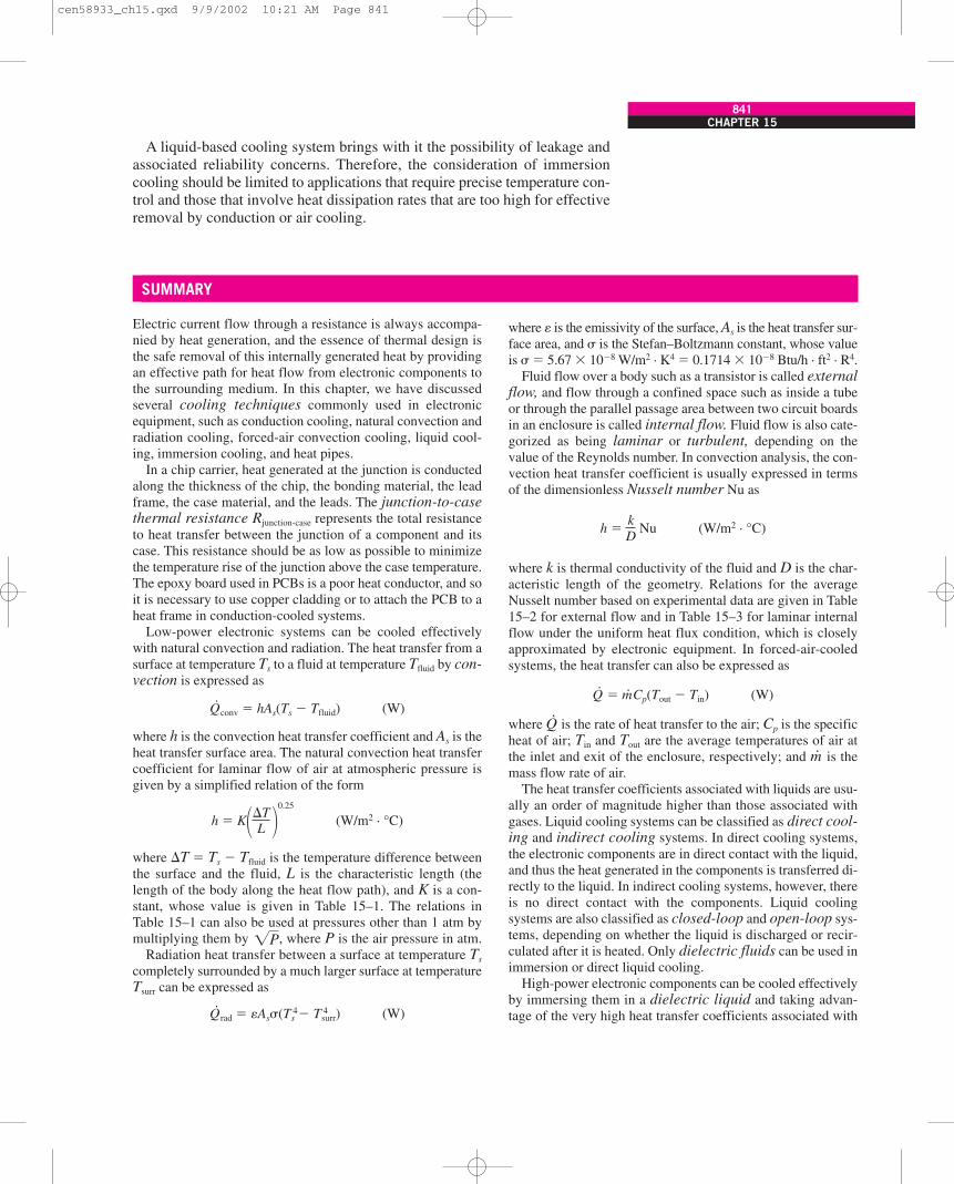
A liquid-based cooling system brings with it the possibility of leakage andassociated reliability concerns. Therefore, the consideration of immersioncooling should be limited to applications that require precise temperature con-trol and those that involve heat dissipation rates that are too high for effectiveremoval by conduction or air cooling.
CHAPTER 15841
SUMMARY
Electric current flow through a resistance is always accompa-nied by heat generation, and the essence of thermal design isthe safe removal of this internally generated heat by providingan effective path for heat flow from electronic components tothe surrounding medium. In this chapter, we have discussedseveral cooling techniques commonly used in electronicequipment, such as conduction cooling, natural convection andradiation cooling, forced-air convection cooling, liquid cool-ing, immersion cooling, and heat pipes.
In a chip carrier, heat generated at the junction is conductedalong the thickness of the chip, the bonding material, the leadframe, the case material, and the leads. The junction-to-casethermal resistance Rjunction-case represents the total resistanceto heat transfer between the junction of a component and itscase. This resistance should be as low as possible to minimizethe temperature rise of the junction above the case temperature.The epoxy board used in PCBs is a poor heat conductor, and soit is necessary to use copper cladding or to attach the PCB to aheat frame in conduction-cooled systems.
Low-power electronic systems can be cooled effectivelywith natural convection and radiation. The heat transfer from asurface at temperature Ts to a fluid at temperature Tfluid by con-vection is expressed as
Q·
conv � hAs(Ts � Tfluid) (W)
where h is the convection heat transfer coefficient and As is theheat transfer surface area. The natural convection heat transfercoefficient for laminar flow of air at atmospheric pressure isgiven by a simplified relation of the form
h � K (W/m2 · °C)
where �T � Ts � Tfluid is the temperature difference betweenthe surface and the fluid, L is the characteristic length (thelength of the body along the heat flow path), and K is a con-stant, whose value is given in Table 15–1. The relations inTable 15–1 can also be used at pressures other than 1 atm bymultiplying them by , where P is the air pressure in atm.
Radiation heat transfer between a surface at temperature Ts
completely surrounded by a much larger surface at temperatureTsurr can be expressed as
Q·
rad � As�(T 4s � T 4
surr) (W)
where is the emissivity of the surface, As is the heat transfer sur-face area, and � is the Stefan–Boltzmann constant, whose valueis � � 5.67 � 10�8 W/m2 · K4 � 0.1714 � 10�8 Btu/h · ft2 · R4.
Fluid flow over a body such as a transistor is called externalflow, and flow through a confined space such as inside a tubeor through the parallel passage area between two circuit boardsin an enclosure is called internal flow. Fluid flow is also cate-gorized as being laminar or turbulent, depending on thevalue of the Reynolds number. In convection analysis, the con-vection heat transfer coefficient is usually expressed in termsof the dimensionless Nusselt number Nu as
h � Nu (W/m2 · °C)
where k is thermal conductivity of the fluid and D is the char-acteristic length of the geometry. Relations for the averageNusselt number based on experimental data are given in Table15–2 for external flow and in Table 15–3 for laminar internalflow under the uniform heat flux condition, which is closelyapproximated by electronic equipment. In forced-air-cooledsystems, the heat transfer can also be expressed as
Q·
� m· Cp(Tout � Tin) (W)
where Q·
is the rate of heat transfer to the air; Cp is the specificheat of air; Tin and Tout are the average temperatures of air atthe inlet and exit of the enclosure, respectively; and m· is themass flow rate of air.
The heat transfer coefficients associated with liquids are usu-ally an order of magnitude higher than those associated withgases. Liquid cooling systems can be classified as direct cool-ing and indirect cooling systems. In direct cooling systems,the electronic components are in direct contact with the liquid,and thus the heat generated in the components is transferred di-rectly to the liquid. In indirect cooling systems, however, thereis no direct contact with the components. Liquid coolingsystems are also classified as closed-loop and open-loop sys-tems, depending on whether the liquid is discharged or recir-culated after it is heated. Only dielectric fluids can be used inimmersion or direct liquid cooling.
High-power electronic components can be cooled effectivelyby immersing them in a dielectric liquid and taking advan-tage of the very high heat transfer coefficients associated with
kD
�P
��TL �
0.25
cen58933_ch15.qxd 9/9/2002 10:21 AM Page 841
842HEAT TRANSFER
boiling. The simplest type of immersion cooling system in-volves an external reservoir that supplies liquid continuallyto the electronic enclosure. This open-loop-type immersioncooling system is simple but often impractical. Immersion
cooling systems usually operate in a closed loop, in that thevapor is condensed and returned to the electronic enclosure in-stead of being purged to the atmosphere.
REFERENCES AND SUGGESTED READING
1. E. P. Black and E. M. Daley. “Thermal DesignConsiderations for Electronic Components.” ASME PaperNo. 70-DE-17, 1970.
2. R. A. Colclaser, D. A. Neaman, and C. F. Hawkins.Electronic Circuit Analysis. New York: John Wiley &Sons, 1984.
3. J. W. Dally. Packaging of Electronic Systems. NewYork: McGraw-Hill, 1990.
4. Design Manual of Cooling Methods for ElectronicEquipment. NAVSHIPS 900-190. Department of theNavy, Bureau of Ships, March 1955.
5. Design Manual of Natural Methods of CoolingElectronic Equipment. NAVSHIPS 900-192.Department of the Navy, Bureau of Ships, November1956.
6. G. N. Ellison. Thermal Computations for ElectronicEquipment. New York: Van Nostrand Reinhold, 1984.
7. J. A. Gardner. “Liquid Cooling Safeguards High-PowerSemiconductors.” Electronics, February 24, 1974, p. 103.
8. R. S. Gaugler. “Heat Transfer Devices.” U.S. Patent2350348, 1944.
9. G. M. Grover, T. P. Cotter, and G. F. Erickson. “Structuresof Very High Thermal Conductivity.” Journal ofApplied Physics 35 (1964), pp. 1190–1191.
10. W. F. Hilbert and F. H. Kube. “Effects on ElectronicEquipment Reliability of Temperature Cycling inEquipment.” Report No. EC-69-400. Final Report,Grumman Aircraft Engineering Corporation, Bethpage,NY, February 1969.
11. U. P. Hwang and K. P. Moran. “Boiling Heat Transfer ofSilicon Integrated Circuits Chip Mounted on a Substrate.”ASME HTD 20 (1981), pp. 53–59.
12. M. Jakob. Heat Transfer. Vol. 1. New York: John Wiley& Sons, 1949.
13. R. D. Johnson. “Enclosures—State of the Art.” NewElectronics, July 29, 1983, p. 29.
14. A. D. Kraus and A. Bar-Cohen. Thermal Analysis andControl of Electronic Equipment. New York:McGraw-Hill/Hemisphere, 1983.
15. Reliability Prediction of Electronic Equipment. U.S.Department of Defense, MIL-HDBK-2178B, NTIS,Springfield, VA, 1974.
16. D. S. Steinberg. Cooling Techniques for ElectronicEquipment. New York: John Wiley & Sons, 1980.
17. A. Zukauskas. “Heat Transfer from Tubes in Cross Flow.”In Advances in Heat Transfer, vol. 8, ed. J. P. Hartnettand T. F. Irvine, Jr. New York: Academic Press, 1972.
PROBLEMS*
Introduction and History
15–1C What invention started the electronic age? Why didthe invention of the transistor mark the beginning of a revolu-tion in that age?
15–2C What is an integrated circuit? What is its significancein the electronics era? What do the initials MSI, LSI, and VLSIstand for?
15–3C When electric current I passes through an electricalelement having a resistance R, why is heat generated in the el-ement? How is the amount of heat generation determined?
15–4C Consider a TV that is wrapped in the blankets fromall sides except its screen. Explain what will happen when theTV is turned on and kept on for a long time, and why. Whatwill happen if the TV is kept on for a few minutes only?
15–5C Consider an incandescent light bulb that is com-pletely wrapped in a towel. Explain what will happen when thelight is turned on and kept on. (P.S. Do not try this at home!)
15–6C A businessman ties a large cloth advertisement ban-ner in front of his car such that it completely blocks the airflowto the radiator. What do you think will happen when he startsthe car and goes on a trip?
*Problems designated by a “C” are concept questions, andstudents are encouraged to answer them all. Problems designatedby an “E” are in English units, and the SI users can ignore them.Problems with an EES-CD icon are solved using EES, andcomplete solutions together with parametric studies are includedon the enclosed CD. Problems with a computer-EES icon arecomprehensive in nature, and are intended to be solved with acomputer, preferably using the EES software that accompaniesthis text.
cen58933_ch15.qxd 9/9/2002 10:21 AM Page 842
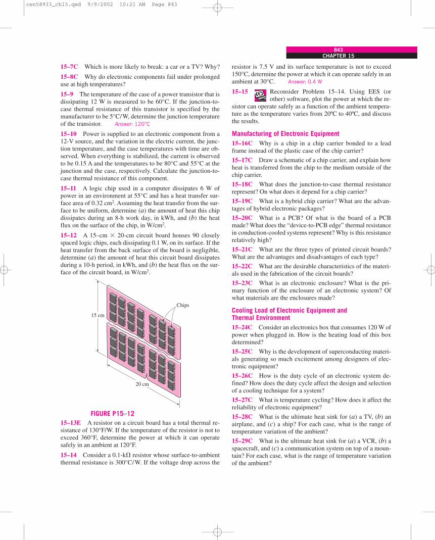
CHAPTER 15843
15–7C Which is more likely to break: a car or a TV? Why?
15–8C Why do electronic components fail under prolongeduse at high temperatures?
15–9 The temperature of the case of a power transistor that isdissipating 12 W is measured to be 60°C. If the junction-to-case thermal resistance of this transistor is specified by themanufacturer to be 5°C/W, determine the junction temperatureof the transistor. Answer: 120°C
15–10 Power is supplied to an electronic component from a12-V source, and the variation in the electric current, the junc-tion temperature, and the case temperatures with time are ob-served. When everything is stabilized, the current is observedto be 0.15 A and the temperatures to be 80°C and 55°C at thejunction and the case, respectively. Calculate the junction-to-case thermal resistance of this component.
15–11 A logic chip used in a computer dissipates 6 W ofpower in an environment at 55°C and has a heat transfer sur-face area of 0.32 cm2. Assuming the heat transfer from the sur-face to be uniform, determine (a) the amount of heat this chipdissipates during an 8-h work day, in kWh, and (b) the heatflux on the surface of the chip, in W/cm2.
15–12 A 15–cm � 20-cm circuit board houses 90 closelyspaced logic chips, each dissipating 0.1 W, on its surface. If theheat transfer from the back surface of the board is negligible,determine (a) the amount of heat this circuit board dissipatesduring a 10-h period, in kWh, and (b) the heat flux on the sur-face of the circuit board, in W/cm2.
15–13E A resistor on a circuit board has a total thermal re-sistance of 130°F/W. If the temperature of the resistor is not toexceed 360°F, determine the power at which it can operatesafely in an ambient at 120°F.
15–14 Consider a 0.1-k� resistor whose surface-to-ambientthermal resistance is 300°C/W. If the voltage drop across the
resistor is 7.5 V and its surface temperature is not to exceed150°C, determine the power at which it can operate safely in anambient at 30°C. Answer: 0.4 W
15–15 Reconsider Problem 15–14. Using EES (orother) software, plot the power at which the re-
sistor can operate safely as a function of the ambient tempera-ture as the temperature varies from 20ºC to 40ºC, and discussthe results.
Manufacturing of Electronic Equipment15–16C Why is a chip in a chip carrier bonded to a leadframe instead of the plastic case of the chip carrier?
15–17C Draw a schematic of a chip carrier, and explain howheat is transferred from the chip to the medium outside of thechip carrier.
15–18C What does the junction-to-case thermal resistancerepresent? On what does it depend for a chip carrier?
15–19C What is a hybrid chip carrier? What are the advan-tages of hybrid electronic packages?
15–20C What is a PCB? Of what is the board of a PCBmade? What does the “device-to-PCB edge” thermal resistancein conduction-cooled systems represent? Why is this resistancerelatively high?
15–21C What are the three types of printed circuit boards?What are the advantages and disadvantages of each type?
15–22C What are the desirable characteristics of the materi-als used in the fabrication of the circuit boards?
15–23C What is an electronic enclosure? What is the pri-mary function of the enclosure of an electronic system? Ofwhat materials are the enclosures made?
Cooling Load of Electronic Equipment andThermal Environment15–24C Consider an electronics box that consumes 120 W ofpower when plugged in. How is the heating load of this boxdetermined?
15–25C Why is the development of superconducting materi-als generating so much excitement among designers of elec-tronic equipment?
15–26C How is the duty cycle of an electronic system de-fined? How does the duty cycle affect the design and selectionof a cooling technique for a system?
15–27C What is temperature cycling? How does it affect thereliability of electronic equipment?
15–28C What is the ultimate heat sink for (a) a TV, (b) anairplane, and (c) a ship? For each case, what is the range oftemperature variation of the ambient?
15–29C What is the ultimate heat sink for (a) a VCR, (b) aspacecraft, and (c) a communication system on top of a moun-tain? For each case, what is the range of temperature variationof the ambient?
Chips
15 cm
20 cm
FIGURE P15–12
cen58933_ch15.qxd 9/9/2002 10:21 AM Page 843
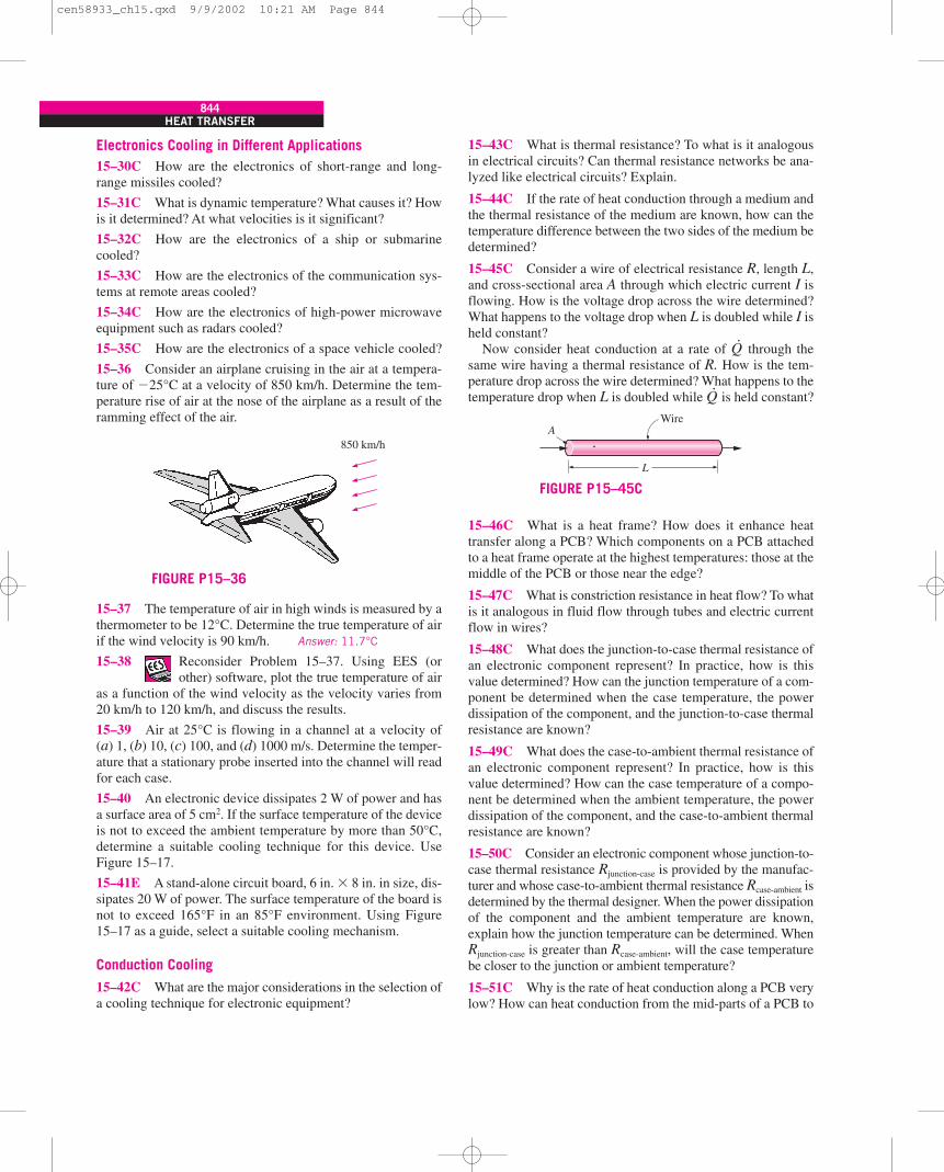
844HEAT TRANSFER
Electronics Cooling in Different Applications15–30C How are the electronics of short-range and long-range missiles cooled?
15–31C What is dynamic temperature? What causes it? Howis it determined? At what velocities is it significant?
15–32C How are the electronics of a ship or submarinecooled?
15–33C How are the electronics of the communication sys-tems at remote areas cooled?
15–34C How are the electronics of high-power microwaveequipment such as radars cooled?
15–35C How are the electronics of a space vehicle cooled?
15–36 Consider an airplane cruising in the air at a tempera-ture of �25°C at a velocity of 850 km/h. Determine the tem-perature rise of air at the nose of the airplane as a result of theramming effect of the air.
15–37 The temperature of air in high winds is measured by athermometer to be 12°C. Determine the true temperature of airif the wind velocity is 90 km/h. Answer: 11.7°C
15–38 Reconsider Problem 15–37. Using EES (orother) software, plot the true temperature of air
as a function of the wind velocity as the velocity varies from20 km/h to 120 km/h, and discuss the results.
15–39 Air at 25°C is flowing in a channel at a velocity of(a) 1, (b) 10, (c) 100, and (d) 1000 m/s. Determine the temper-ature that a stationary probe inserted into the channel will readfor each case.
15–40 An electronic device dissipates 2 W of power and hasa surface area of 5 cm2. If the surface temperature of the deviceis not to exceed the ambient temperature by more than 50°C,determine a suitable cooling technique for this device. UseFigure 15–17.
15–41E A stand-alone circuit board, 6 in. � 8 in. in size, dis-sipates 20 W of power. The surface temperature of the board isnot to exceed 165°F in an 85°F environment. Using Figure15–17 as a guide, select a suitable cooling mechanism.
Conduction Cooling
15–42C What are the major considerations in the selection ofa cooling technique for electronic equipment?
15–43C What is thermal resistance? To what is it analogousin electrical circuits? Can thermal resistance networks be ana-lyzed like electrical circuits? Explain.
15–44C If the rate of heat conduction through a medium andthe thermal resistance of the medium are known, how can thetemperature difference between the two sides of the medium bedetermined?
15–45C Consider a wire of electrical resistance R, length L,and cross-sectional area A through which electric current I isflowing. How is the voltage drop across the wire determined?What happens to the voltage drop when L is doubled while I isheld constant?
Now consider heat conduction at a rate of Q·
through thesame wire having a thermal resistance of R. How is the tem-perature drop across the wire determined? What happens to thetemperature drop when L is doubled while Q
·is held constant?
15–46C What is a heat frame? How does it enhance heattransfer along a PCB? Which components on a PCB attachedto a heat frame operate at the highest temperatures: those at themiddle of the PCB or those near the edge?
15–47C What is constriction resistance in heat flow? To whatis it analogous in fluid flow through tubes and electric currentflow in wires?
15–48C What does the junction-to-case thermal resistance ofan electronic component represent? In practice, how is thisvalue determined? How can the junction temperature of a com-ponent be determined when the case temperature, the powerdissipation of the component, and the junction-to-case thermalresistance are known?
15–49C What does the case-to-ambient thermal resistance ofan electronic component represent? In practice, how is thisvalue determined? How can the case temperature of a compo-nent be determined when the ambient temperature, the powerdissipation of the component, and the case-to-ambient thermalresistance are known?
15–50C Consider an electronic component whose junction-to-case thermal resistance Rjunction-case is provided by the manufac-turer and whose case-to-ambient thermal resistance Rcase-ambient isdetermined by the thermal designer. When the power dissipationof the component and the ambient temperature are known,explain how the junction temperature can be determined. WhenRjunction-case is greater than Rcase-ambient, will the case temperaturebe closer to the junction or ambient temperature?
15–51C Why is the rate of heat conduction along a PCB verylow? How can heat conduction from the mid-parts of a PCB to
850 km/h
FIGURE P15–36
Wire
L
A
FIGURE P15–45C
cen58933_ch15.qxd 9/9/2002 10:21 AM Page 844
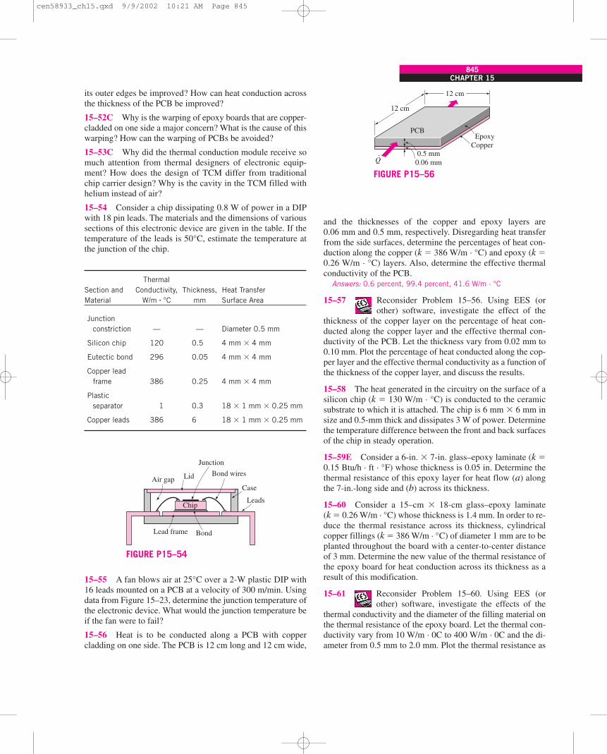
CHAPTER 15845
its outer edges be improved? How can heat conduction acrossthe thickness of the PCB be improved?
15–52C Why is the warping of epoxy boards that are copper-cladded on one side a major concern? What is the cause of thiswarping? How can the warping of PCBs be avoided?
15–53C Why did the thermal conduction module receive somuch attention from thermal designers of electronic equip-ment? How does the design of TCM differ from traditionalchip carrier design? Why is the cavity in the TCM filled withhelium instead of air?
15–54 Consider a chip dissipating 0.8 W of power in a DIPwith 18 pin leads. The materials and the dimensions of varioussections of this electronic device are given in the table. If thetemperature of the leads is 50°C, estimate the temperature atthe junction of the chip.
Thermal Section and Conductivity, Thickness, Heat Transfer Material W/m · °C mm Surface Area
Junction constriction — — Diameter 0.5 mm
Silicon chip 120 0.5 4 mm � 4 mm
Eutectic bond 296 0.05 4 mm � 4 mm
Copper lead frame 386 0.25 4 mm � 4 mm
Plastic separator 1 0.3 18 � 1 mm � 0.25 mm
Copper leads 386 6 18 � 1 mm � 0.25 mm
15–55 A fan blows air at 25°C over a 2-W plastic DIP with16 leads mounted on a PCB at a velocity of 300 m/min. Usingdata from Figure 15–23, determine the junction temperature ofthe electronic device. What would the junction temperature beif the fan were to fail?
15–56 Heat is to be conducted along a PCB with coppercladding on one side. The PCB is 12 cm long and 12 cm wide,
and the thicknesses of the copper and epoxy layers are0.06 mm and 0.5 mm, respectively. Disregarding heat transferfrom the side surfaces, determine the percentages of heat con-duction along the copper (k � 386 W/m · °C) and epoxy (k �0.26 W/m · °C) layers. Also, determine the effective thermalconductivity of the PCB.
Answers: 0.6 percent, 99.4 percent, 41.6 W/m · °C
15–57 Reconsider Problem 15–56. Using EES (orother) software, investigate the effect of the
thickness of the copper layer on the percentage of heat con-ducted along the copper layer and the effective thermal con-ductivity of the PCB. Let the thickness vary from 0.02 mm to0.10 mm. Plot the percentage of heat conducted along the cop-per layer and the effective thermal conductivity as a function ofthe thickness of the copper layer, and discuss the results.
15–58 The heat generated in the circuitry on the surface of asilicon chip (k � 130 W/m · °C) is conducted to the ceramicsubstrate to which it is attached. The chip is 6 mm � 6 mm insize and 0.5-mm thick and dissipates 3 W of power. Determinethe temperature difference between the front and back surfacesof the chip in steady operation.
15–59E Consider a 6-in. � 7-in. glass–epoxy laminate (k �0.15 Btu/h · ft · °F) whose thickness is 0.05 in. Determine thethermal resistance of this epoxy layer for heat flow (a) alongthe 7-in.-long side and (b) across its thickness.
15–60 Consider a 15–cm � 18-cm glass–epoxy laminate(k � 0.26 W/m · °C) whose thickness is 1.4 mm. In order to re-duce the thermal resistance across its thickness, cylindricalcopper fillings (k � 386 W/m · °C) of diameter 1 mm are to beplanted throughout the board with a center-to-center distanceof 3 mm. Determine the new value of the thermal resistance ofthe epoxy board for heat conduction across its thickness as aresult of this modification.
15–61 Reconsider Problem 15–60. Using EES (orother) software, investigate the effects of the
thermal conductivity and the diameter of the filling material onthe thermal resistance of the epoxy board. Let the thermal con-ductivity vary from 10 W/m · 0C to 400 W/m · 0C and the di-ameter from 0.5 mm to 2.0 mm. Plot the thermal resistance as
Case
Leads
Bond
Chip
Lead frame
LidAir gapBond wires
Junction
FIGURE P15–54
EpoxyCopper
PCB
.Q
12 cm
12 cm
0.5 mm0.06 mm
FIGURE P15–56
cen58933_ch15.qxd 9/9/2002 10:21 AM Page 845
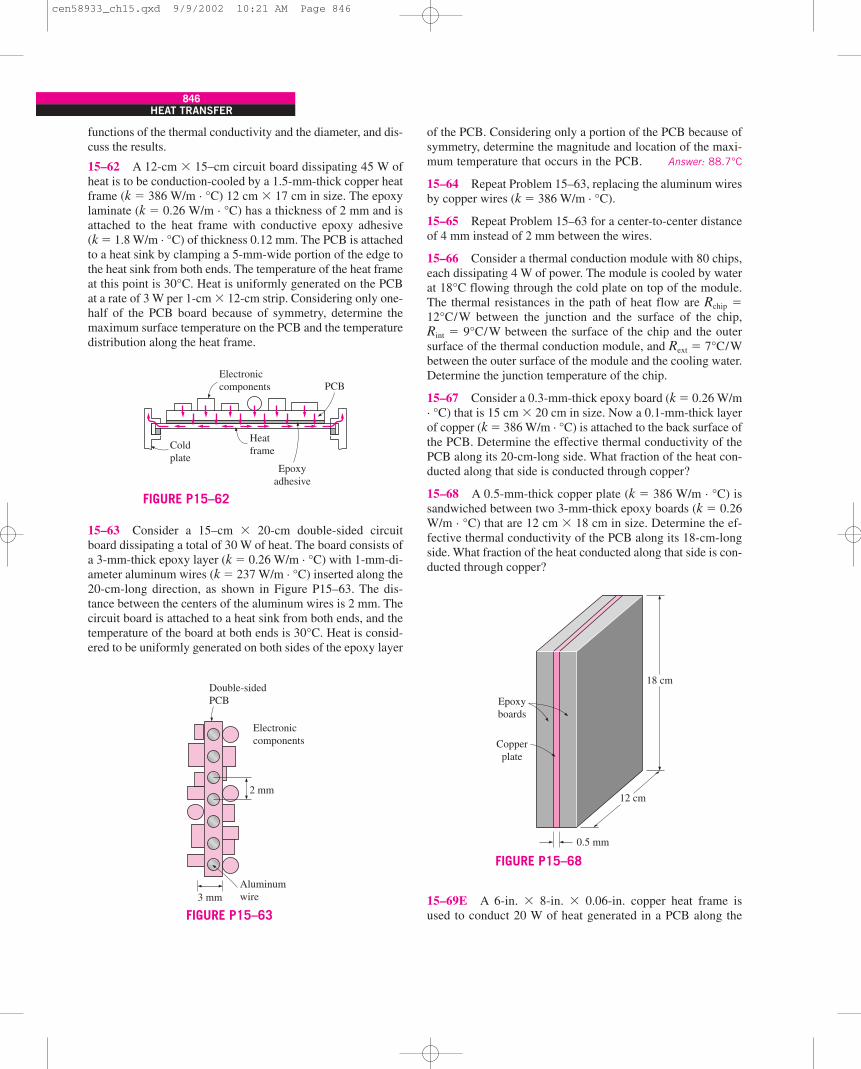
846HEAT TRANSFER
functions of the thermal conductivity and the diameter, and dis-cuss the results.
15–62 A 12-cm � 15–cm circuit board dissipating 45 W ofheat is to be conduction-cooled by a 1.5-mm-thick copper heatframe (k � 386 W/m · °C) 12 cm � 17 cm in size. The epoxylaminate (k � 0.26 W/m · °C) has a thickness of 2 mm and isattached to the heat frame with conductive epoxy adhesive(k � 1.8 W/m · °C) of thickness 0.12 mm. The PCB is attachedto a heat sink by clamping a 5-mm-wide portion of the edge tothe heat sink from both ends. The temperature of the heat frameat this point is 30°C. Heat is uniformly generated on the PCBat a rate of 3 W per 1-cm � 12-cm strip. Considering only one-half of the PCB board because of symmetry, determine themaximum surface temperature on the PCB and the temperaturedistribution along the heat frame.
15–63 Consider a 15–cm � 20-cm double-sided circuitboard dissipating a total of 30 W of heat. The board consists ofa 3-mm-thick epoxy layer (k � 0.26 W/m · °C) with 1-mm-di-ameter aluminum wires (k � 237 W/m · °C) inserted along the20-cm-long direction, as shown in Figure P15–63. The dis-tance between the centers of the aluminum wires is 2 mm. Thecircuit board is attached to a heat sink from both ends, and thetemperature of the board at both ends is 30°C. Heat is consid-ered to be uniformly generated on both sides of the epoxy layer
of the PCB. Considering only a portion of the PCB because ofsymmetry, determine the magnitude and location of the maxi-mum temperature that occurs in the PCB. Answer: 88.7°C
15–64 Repeat Problem 15–63, replacing the aluminum wiresby copper wires (k � 386 W/m · °C).
15–65 Repeat Problem 15–63 for a center-to-center distanceof 4 mm instead of 2 mm between the wires.
15–66 Consider a thermal conduction module with 80 chips,each dissipating 4 W of power. The module is cooled by waterat 18°C flowing through the cold plate on top of the module.The thermal resistances in the path of heat flow are Rchip �12°C/W between the junction and the surface of the chip,Rint � 9°C/W between the surface of the chip and the outersurface of the thermal conduction module, and Rext � 7°C/Wbetween the outer surface of the module and the cooling water.Determine the junction temperature of the chip.
15–67 Consider a 0.3-mm-thick epoxy board (k � 0.26 W/m· °C) that is 15 cm � 20 cm in size. Now a 0.1-mm-thick layerof copper (k � 386 W/m · °C) is attached to the back surface ofthe PCB. Determine the effective thermal conductivity of thePCB along its 20-cm-long side. What fraction of the heat con-ducted along that side is conducted through copper?
15–68 A 0.5-mm-thick copper plate (k � 386 W/m · °C) issandwiched between two 3-mm-thick epoxy boards (k � 0.26W/m · °C) that are 12 cm � 18 cm in size. Determine the ef-fective thermal conductivity of the PCB along its 18-cm-longside. What fraction of the heat conducted along that side is con-ducted through copper?
15–69E A 6-in. � 8-in. � 0.06-in. copper heat frame isused to conduct 20 W of heat generated in a PCB along the
Electroniccomponents
Heatframe
PCB
Coldplate
Epoxyadhesive
FIGURE P15–62
Double-sidedPCB
Electroniccomponents
2 mm
Aluminumwire3 mm
FIGURE P15–63
0.5 mm
12 cm
18 cm
Epoxyboards
Copperplate
FIGURE P15–68
cen58933_ch15.qxd 9/9/2002 10:21 AM Page 846
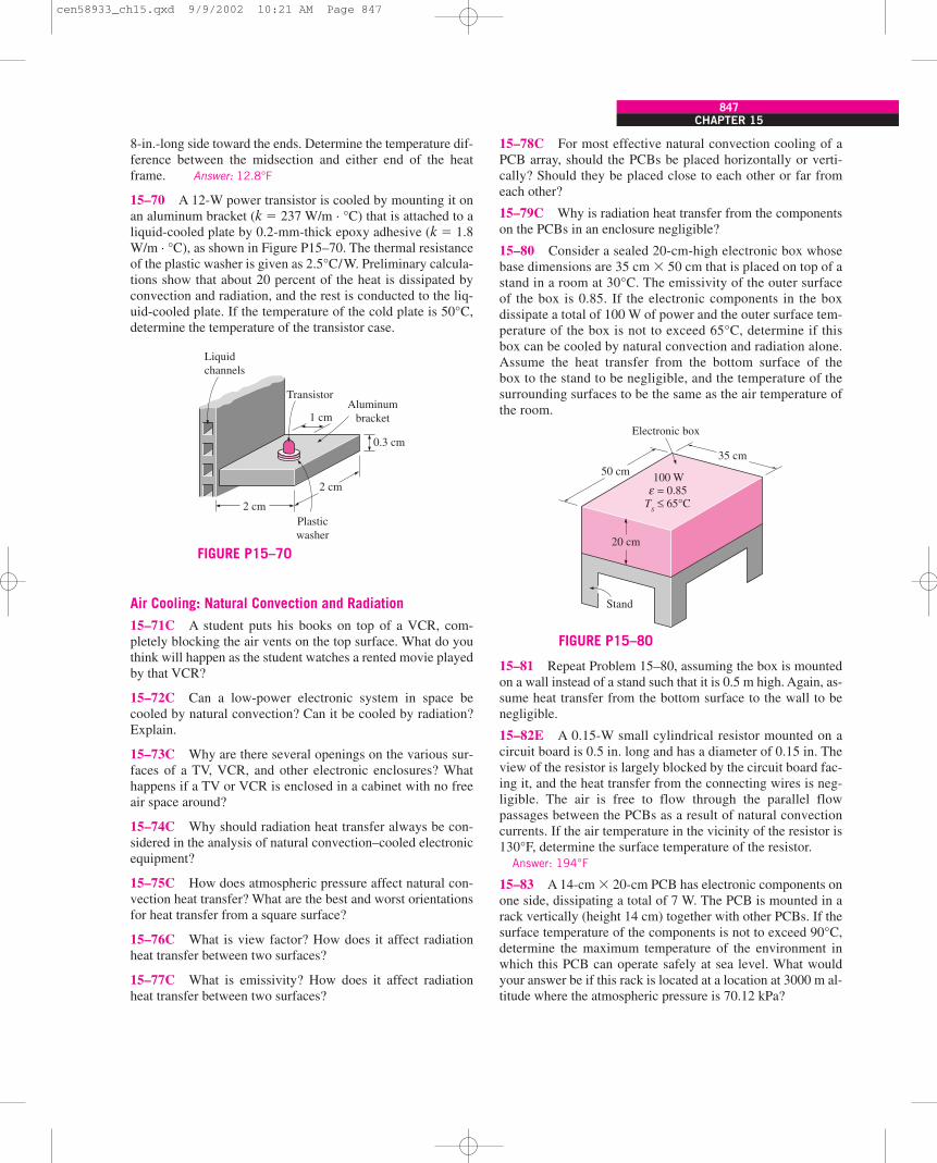
CHAPTER 15847
8-in.-long side toward the ends. Determine the temperature dif-ference between the midsection and either end of the heatframe. Answer: 12.8°F
15–70 A 12-W power transistor is cooled by mounting it onan aluminum bracket (k � 237 W/m · °C) that is attached to aliquid-cooled plate by 0.2-mm-thick epoxy adhesive (k � 1.8W/m · °C), as shown in Figure P15–70. The thermal resistanceof the plastic washer is given as 2.5°C/W. Preliminary calcula-tions show that about 20 percent of the heat is dissipated byconvection and radiation, and the rest is conducted to the liq-uid-cooled plate. If the temperature of the cold plate is 50°C,determine the temperature of the transistor case.
Air Cooling: Natural Convection and Radiation
15–71C A student puts his books on top of a VCR, com-pletely blocking the air vents on the top surface. What do youthink will happen as the student watches a rented movie playedby that VCR?
15–72C Can a low-power electronic system in space becooled by natural convection? Can it be cooled by radiation?Explain.
15–73C Why are there several openings on the various sur-faces of a TV, VCR, and other electronic enclosures? Whathappens if a TV or VCR is enclosed in a cabinet with no freeair space around?
15–74C Why should radiation heat transfer always be con-sidered in the analysis of natural convection–cooled electronicequipment?
15–75C How does atmospheric pressure affect natural con-vection heat transfer? What are the best and worst orientationsfor heat transfer from a square surface?
15–76C What is view factor? How does it affect radiationheat transfer between two surfaces?
15–77C What is emissivity? How does it affect radiationheat transfer between two surfaces?
15–78C For most effective natural convection cooling of aPCB array, should the PCBs be placed horizontally or verti-cally? Should they be placed close to each other or far fromeach other?
15–79C Why is radiation heat transfer from the componentson the PCBs in an enclosure negligible?
15–80 Consider a sealed 20-cm-high electronic box whosebase dimensions are 35 cm � 50 cm that is placed on top of astand in a room at 30°C. The emissivity of the outer surfaceof the box is 0.85. If the electronic components in the boxdissipate a total of 100 W of power and the outer surface tem-perature of the box is not to exceed 65°C, determine if thisbox can be cooled by natural convection and radiation alone.Assume the heat transfer from the bottom surface of thebox to the stand to be negligible, and the temperature of thesurrounding surfaces to be the same as the air temperature ofthe room.
15–81 Repeat Problem 15–80, assuming the box is mountedon a wall instead of a stand such that it is 0.5 m high. Again, as-sume heat transfer from the bottom surface to the wall to benegligible.
15–82E A 0.15-W small cylindrical resistor mounted on acircuit board is 0.5 in. long and has a diameter of 0.15 in. Theview of the resistor is largely blocked by the circuit board fac-ing it, and the heat transfer from the connecting wires is neg-ligible. The air is free to flow through the parallel flowpassages between the PCBs as a result of natural convectioncurrents. If the air temperature in the vicinity of the resistor is130°F, determine the surface temperature of the resistor.
Answer: 194°F
15–83 A 14-cm � 20-cm PCB has electronic components onone side, dissipating a total of 7 W. The PCB is mounted in arack vertically (height 14 cm) together with other PCBs. If thesurface temperature of the components is not to exceed 90°C,determine the maximum temperature of the environment inwhich this PCB can operate safely at sea level. What wouldyour answer be if this rack is located at a location at 3000 m al-titude where the atmospheric pressure is 70.12 kPa?
TransistorAluminum
bracket
0.3 cm
2 cm
Plasticwasher
2 cm
1 cm
Liquidchannels
FIGURE P15–7020 cm
Stand
50 cm35 cm
100 W = 0.85 ≤ 65°C
εTs
Electronic box
FIGURE P15–80
cen58933_ch15.qxd 9/9/2002 10:21 AM Page 847
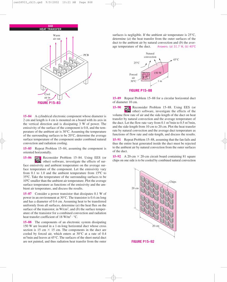
848HEAT TRANSFER
15–84 A cylindrical electronic component whose diameter is2 cm and length is 4 cm is mounted on a board with its axis inthe vertical direction and is dissipating 3 W of power. Theemissivity of the surface of the component is 0.8, and the tem-perature of the ambient air is 30°C. Assuming the temperatureof the surrounding surfaces to be 20°C, determine the averagesurface temperature of the component under combined naturalconvection and radiation cooling.
15–85 Repeat Problem 15–84, assuming the component isoriented horizontally.
15–86 Reconsider Problem 15–84. Using EES (orother) software, investigate the effects of sur-
face emissivity and ambient temperature on the average sur-face temperature of the component. Let the emissivity varyfrom 0.1 to 1.0 and the ambient temperature from 15ºC to35ºC. Take the temperature of the surrounding surfaces to be10ºC smaller than the ambient air temperature. Plot the averagesurface temperature as functions of the emissivity and the am-bient air temperature, and discuss the results.
15–87 Consider a power transistor that dissipates 0.1 W ofpower in an environment at 30°C. The transistor is 0.4 cm longand has a diameter of 0.4 cm. Assuming heat to be transferreduniformly from all surfaces, determine (a) the heat flux on thesurface of the transistor, in W/cm2, and (b) the surface temper-ature of the transistor for a combined convection and radiationheat transfer coefficient of 18 W/m2 · °C.
15–88 The components of an electronic system dissipating150 W are located in a 1-m-long horizontal duct whose crosssection is 15 cm � 15 cm. The components in the duct arecooled by forced air, which enters at 30°C at a rate of 0.4m3/min and leaves at 45°C. The surfaces of the sheet metal ductare not painted, and thus radiation heat transfer from the outer
surfaces is negligible. If the ambient air temperature is 25°C,determine (a) the heat transfer from the outer surfaces of theduct to the ambient air by natural convection and (b) the aver-age temperature of the duct. Answers: (a) 31.7 W, (b) 40°C
15–89 Repeat Problem 15–88 for a circular horizontal ductof diameter 10 cm.
15–90 Reconsider Problem 15–88. Using EES (orother) software, investigate the effects of the
volume flow rate of air and the side-length of the duct on heattransfer by natural convection and the average temperature ofthe duct. Let the flow rate vary from 0.1 m3/min to 0.5 m3/min,and the side-length from 10 cm to 20 cm. Plot the heat transferrate by natural convection and the average duct temperature asfunctions of flow rate and side-length, and discuss the results.
15–91 Repeat Problem 15–88, assuming that the fan fails andthus the entire heat generated inside the duct must be rejectedto the ambient air by natural convection from the outer surfacesof the duct.
15–92 A 20-cm � 20-cm circuit board containing 81 squarechips on one side is to be cooled by combined natural convection
PCB
Coolair in
Warmair out
FIGURE P15–83
45°C
Naturalconvection
25°C
Forcedair
30°C 1 m
150 W
FIGURE P15–88
Chips
20 cm
20 cm
FIGURE P15–92
cen58933_ch15.qxd 9/9/2002 10:21 AM Page 848
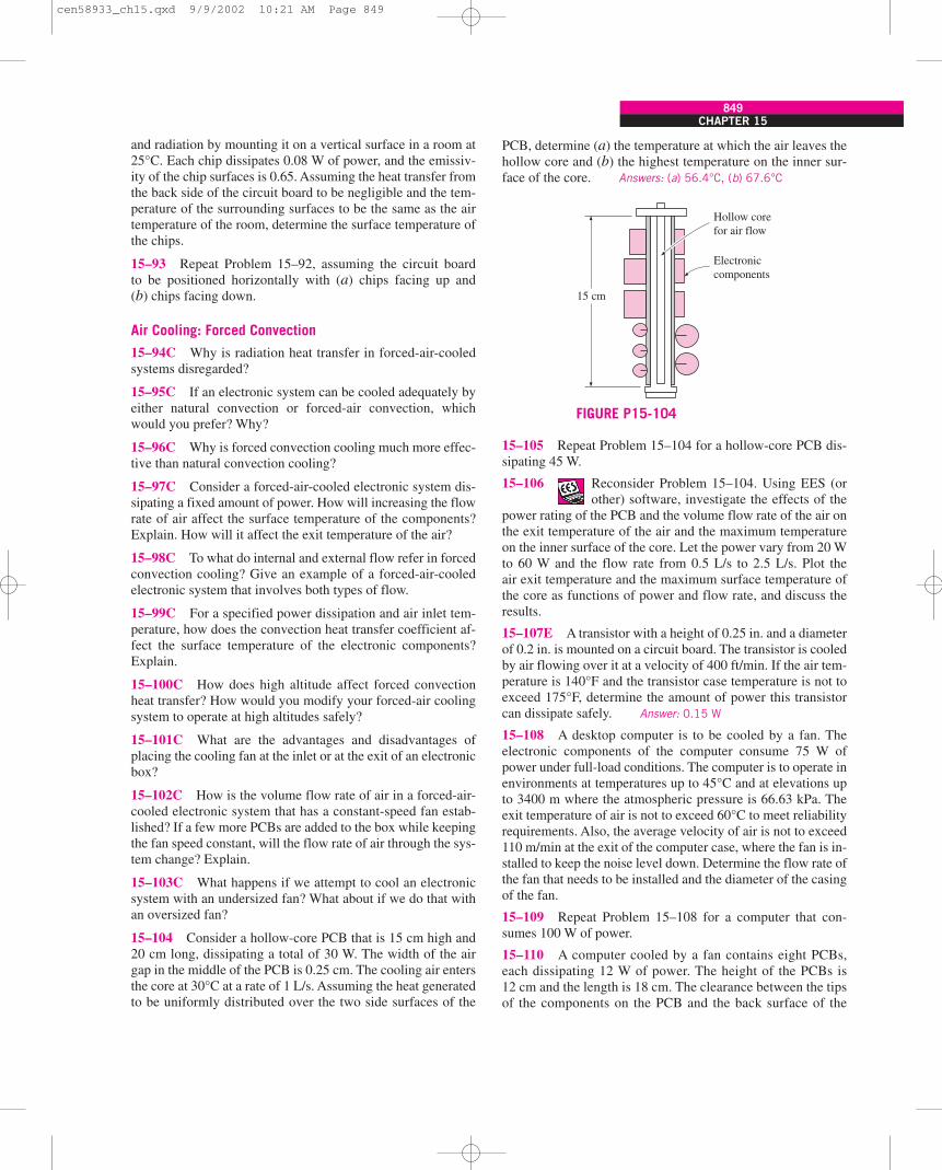
CHAPTER 15849
and radiation by mounting it on a vertical surface in a room at25°C. Each chip dissipates 0.08 W of power, and the emissiv-ity of the chip surfaces is 0.65. Assuming the heat transfer fromthe back side of the circuit board to be negligible and the tem-perature of the surrounding surfaces to be the same as the airtemperature of the room, determine the surface temperature ofthe chips.
15–93 Repeat Problem 15–92, assuming the circuit boardto be positioned horizontally with (a) chips facing up and(b) chips facing down.
Air Cooling: Forced Convection
15–94C Why is radiation heat transfer in forced-air-cooledsystems disregarded?
15–95C If an electronic system can be cooled adequately byeither natural convection or forced-air convection, whichwould you prefer? Why?
15–96C Why is forced convection cooling much more effec-tive than natural convection cooling?
15–97C Consider a forced-air-cooled electronic system dis-sipating a fixed amount of power. How will increasing the flowrate of air affect the surface temperature of the components?Explain. How will it affect the exit temperature of the air?
15–98C To what do internal and external flow refer in forcedconvection cooling? Give an example of a forced-air-cooledelectronic system that involves both types of flow.
15–99C For a specified power dissipation and air inlet tem-perature, how does the convection heat transfer coefficient af-fect the surface temperature of the electronic components?Explain.
15–100C How does high altitude affect forced convectionheat transfer? How would you modify your forced-air coolingsystem to operate at high altitudes safely?
15–101C What are the advantages and disadvantages ofplacing the cooling fan at the inlet or at the exit of an electronicbox?
15–102C How is the volume flow rate of air in a forced-air-cooled electronic system that has a constant-speed fan estab-lished? If a few more PCBs are added to the box while keepingthe fan speed constant, will the flow rate of air through the sys-tem change? Explain.
15–103C What happens if we attempt to cool an electronicsystem with an undersized fan? What about if we do that withan oversized fan?
15–104 Consider a hollow-core PCB that is 15 cm high and20 cm long, dissipating a total of 30 W. The width of the airgap in the middle of the PCB is 0.25 cm. The cooling air entersthe core at 30°C at a rate of 1 L/s. Assuming the heat generatedto be uniformly distributed over the two side surfaces of the
PCB, determine (a) the temperature at which the air leaves thehollow core and (b) the highest temperature on the inner sur-face of the core. Answers: (a) 56.4°C, (b) 67.6°C
15–105 Repeat Problem 15–104 for a hollow-core PCB dis-sipating 45 W.
15–106 Reconsider Problem 15–104. Using EES (orother) software, investigate the effects of the
power rating of the PCB and the volume flow rate of the air onthe exit temperature of the air and the maximum temperatureon the inner surface of the core. Let the power vary from 20 Wto 60 W and the flow rate from 0.5 L/s to 2.5 L/s. Plot theair exit temperature and the maximum surface temperature ofthe core as functions of power and flow rate, and discuss theresults.
15–107E A transistor with a height of 0.25 in. and a diameterof 0.2 in. is mounted on a circuit board. The transistor is cooledby air flowing over it at a velocity of 400 ft/min. If the air tem-perature is 140°F and the transistor case temperature is not toexceed 175°F, determine the amount of power this transistorcan dissipate safely. Answer: 0.15 W
15–108 A desktop computer is to be cooled by a fan. Theelectronic components of the computer consume 75 W ofpower under full-load conditions. The computer is to operate inenvironments at temperatures up to 45°C and at elevations upto 3400 m where the atmospheric pressure is 66.63 kPa. Theexit temperature of air is not to exceed 60°C to meet reliabilityrequirements. Also, the average velocity of air is not to exceed110 m/min at the exit of the computer case, where the fan is in-stalled to keep the noise level down. Determine the flow rate ofthe fan that needs to be installed and the diameter of the casingof the fan.
15–109 Repeat Problem 15–108 for a computer that con-sumes 100 W of power.
15–110 A computer cooled by a fan contains eight PCBs,each dissipating 12 W of power. The height of the PCBs is12 cm and the length is 18 cm. The clearance between the tipsof the components on the PCB and the back surface of the
Electroniccomponents
Hollow corefor air flow
15 cm
FIGURE P15-104
cen58933_ch15.qxd 9/9/2002 10:21 AM Page 849
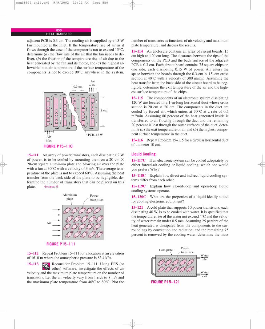
850HEAT TRANSFER
adjacent PCB is 0.3 cm. The cooling air is supplied by a 15-Wfan mounted at the inlet. If the temperature rise of air as itflows through the case of the computer is not to exceed 15°C,determine (a) the flow rate of the air that the fan needs to de-liver, (b) the fraction of the temperature rise of air due to theheat generated by the fan and its motor, and (c) the highest al-lowable inlet air temperature if the surface temperature of thecomponents is not to exceed 90°C anywhere in the system.
15–111 An array of power transistors, each dissipating 2 Wof power, is to be cooled by mounting them on a 20-cm �20-cm square aluminum plate and blowing air over the platewith a fan at 30°C with a velocity of 3 m/s. The average tem-perature of the plate is not to exceed 60°C. Assuming the heattransfer from the back side of the plate to be negligible, de-termine the number of transistors that can be placed on thisplate. Answer: 9
15–112 Repeat Problem 15–111 for a location at an elevationof 1610 m where the atmospheric pressure is 83.4 kPa.
15–113 Reconsider Problem 15–111. Using EES (orother) software, investigate the effects of air
velocity and the maximum plate temperature on the number oftransistors. Let the air velocity vary from 1 rn/s to 8 m/s andthe maximum plate temperature from 40ºC to 80ºC. Plot the
number of transistors as functions of air velocity and maximumplate temperature, and discuss the results.
15–114 An enclosure contains an array of circuit boards, 15cm high and 20 cm long. The clearance between the tips of thecomponents on the PCB and the back surface of the adjacentPCB is 0.3 cm. Each circuit board contains 75 square chips onone side, each dissipating 0.15 W of power. Air enters thespace between the boards through the 0.3-cm � 15–cm crosssection at 40°C with a velocity of 300 m/min. Assuming theheat transfer from the back side of the circuit board to be neg-ligible, determine the exit temperature of the air and the high-est surface temperature of the chips.
15–115 The components of an electronic system dissipating120 W are located in a 1-m-long horizontal duct whose crosssection is 20 cm � 20 cm. The components in the duct arecooled by forced air, which enters at 30°C at a rate of 0.5m3/min. Assuming 80 percent of the heat generated inside istransferred to air flowing through the duct and the remaining20 percent is lost through the outer surfaces of the duct, deter-mine (a) the exit temperature of air and (b) the highest compo-nent surface temperature in the duct.
15–116 Repeat Problem 15–115 for a circular horizontal ductof diameter 10 cm.
Liquid Cooling
15–117C If an electronic system can be cooled adequately byeither forced-air cooling or liquid cooling, which one wouldyou prefer? Why?
15–118C Explain how direct and indirect liquid cooling sys-tems differ from each other.
15–119C Explain how closed-loop and open-loop liquidcooling systems operate.
15–120C What are the properties of a liquid ideally suitedfor cooling electronic equipment?
15–121 A cold plate that supports 10 power transistors, eachdissipating 40 W, is to be cooled with water. It is specified thatthe temperature rise of the water not exceed 4°C and the veloc-ity of water remain under 0.5 m/s. Assuming 25 percent of theheat generated is dissipated from the components to the sur-roundings by convection and radiation, and the remaining 75percent is removed by the cooling water, determine the mass
PCB, 12 WAirinlet
18 cm
0.3 cm
Airoutlet
FIGURE P15–110
Powertransistors
Aluminumplate
Air
FIGURE P15–111Cold plate Power
transistorWaterinlet
Waterexit
FIGURE P15–121
cen58933_ch15.qxd 9/9/2002 10:21 AM Page 850
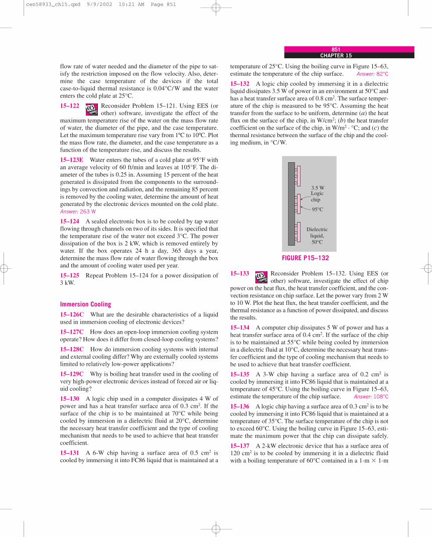
CHAPTER 15851
flow rate of water needed and the diameter of the pipe to sat-isfy the restriction imposed on the flow velocity. Also, deter-mine the case temperature of the devices if the totalcase-to-liquid thermal resistance is 0.04°C/W and the waterenters the cold plate at 25°C.
15–122 Reconsider Problem 15–121. Using EES (orother) software, investigate the effect of the
maximum temperature rise of the water on the mass flow rateof water, the diameter of the pipe, and the case temperature.Let the maximum temperature rise vary from 1ºC to 10ºC. Plotthe mass flow rate, the diameter, and the case temperature as afunction of the temperature rise, and discuss the results.
15–123E Water enters the tubes of a cold plate at 95°F withan average velocity of 60 ft/min and leaves at 105°F. The di-ameter of the tubes is 0.25 in. Assuming 15 percent of the heatgenerated is dissipated from the components to the surround-ings by convection and radiation, and the remaining 85 percentis removed by the cooling water, determine the amount of heatgenerated by the electronic devices mounted on the cold plate.Answer: 263 W
15–124 A sealed electronic box is to be cooled by tap waterflowing through channels on two of its sides. It is specified thatthe temperature rise of the water not exceed 3°C. The powerdissipation of the box is 2 kW, which is removed entirely bywater. If the box operates 24 h a day, 365 days a year,determine the mass flow rate of water flowing through the boxand the amount of cooling water used per year.
15–125 Repeat Problem 15–124 for a power dissipation of3 kW.
Immersion Cooling
15–126C What are the desirable characteristics of a liquidused in immersion cooling of electronic devices?
15–127C How does an open-loop immersion cooling systemoperate? How does it differ from closed-loop cooling systems?
15–128C How do immersion cooling systems with internaland external cooling differ? Why are externally cooled systemslimited to relatively low-power applications?
15–129C Why is boiling heat transfer used in the cooling ofvery high-power electronic devices instead of forced air or liq-uid cooling?
15–130 A logic chip used in a computer dissipates 4 W ofpower and has a heat transfer surface area of 0.3 cm2. If thesurface of the chip is to be maintained at 70°C while beingcooled by immersion in a dielectric fluid at 20°C, determinethe necessary heat transfer coefficient and the type of coolingmechanism that needs to be used to achieve that heat transfercoefficient.
15–131 A 6-W chip having a surface area of 0.5 cm2 iscooled by immersing it into FC86 liquid that is maintained at a
temperature of 25°C. Using the boiling curve in Figure 15–63,estimate the temperature of the chip surface. Answer: 82°C
15–132 A logic chip cooled by immersing it in a dielectricliquid dissipates 3.5 W of power in an environment at 50°C andhas a heat transfer surface area of 0.8 cm2. The surface temper-ature of the chip is measured to be 95°C. Assuming the heattransfer from the surface to be uniform, determine (a) the heatflux on the surface of the chip, in W/cm2; (b) the heat transfercoefficient on the surface of the chip, in W/m2 · °C; and (c) thethermal resistance between the surface of the chip and the cool-ing medium, in °C/W.
15–133 Reconsider Problem 15–132. Using EES (orother) software, investigate the effect of chip
power on the heat flux, the heat transfer coefficient, and the con-vection resistance on chip surface. Let the power vary from 2 Wto 10 W. Plot the heat flux, the heat transfer coefficient, and thethermal resistance as a function of power dissipated, and discussthe results.
15–134 A computer chip dissipates 5 W of power and has aheat transfer surface area of 0.4 cm2. If the surface of the chipis to be maintained at 55°C while being cooled by immersionin a dielectric fluid at 10°C, determine the necessary heat trans-fer coefficient and the type of cooling mechanism that needs tobe used to achieve that heat transfer coefficient.
15–135 A 3-W chip having a surface area of 0.2 cm2 iscooled by immersing it into FC86 liquid that is maintained at atemperature of 45°C. Using the boiling curve in Figure 15–63,estimate the temperature of the chip surface. Answer: 108°C
15–136 A logic chip having a surface area of 0.3 cm2 is to becooled by immersing it into FC86 liquid that is maintained at atemperature of 35°C. The surface temperature of the chip is notto exceed 60°C. Using the boiling curve in Figure 15–63, esti-mate the maximum power that the chip can dissipate safely.
15–137 A 2-kW electronic device that has a surface area of120 cm2 is to be cooled by immersing it in a dielectric fluidwith a boiling temperature of 60°C contained in a 1-m � 1-m
Dielectricliquid,50°C
Logic chip
95°C
3.5 W
FIGURE P15–132
cen58933_ch15.qxd 9/9/2002 10:21 AM Page 851
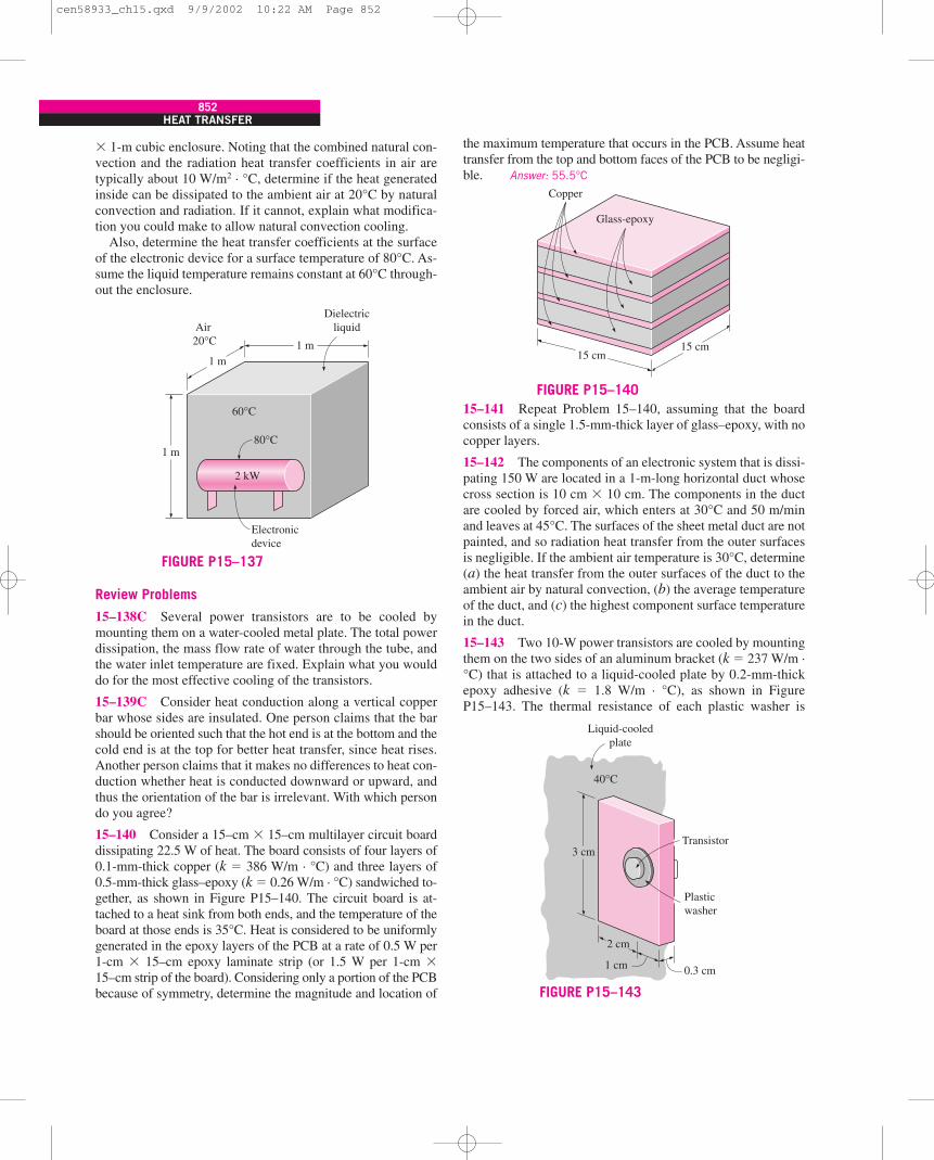
852HEAT TRANSFER
� 1-m cubic enclosure. Noting that the combined natural con-vection and the radiation heat transfer coefficients in air aretypically about 10 W/m2 · °C, determine if the heat generatedinside can be dissipated to the ambient air at 20°C by naturalconvection and radiation. If it cannot, explain what modifica-tion you could make to allow natural convection cooling.
Also, determine the heat transfer coefficients at the surfaceof the electronic device for a surface temperature of 80°C. As-sume the liquid temperature remains constant at 60°C through-out the enclosure.
Review Problems
15–138C Several power transistors are to be cooled bymounting them on a water-cooled metal plate. The total powerdissipation, the mass flow rate of water through the tube, andthe water inlet temperature are fixed. Explain what you woulddo for the most effective cooling of the transistors.
15–139C Consider heat conduction along a vertical copperbar whose sides are insulated. One person claims that the barshould be oriented such that the hot end is at the bottom and thecold end is at the top for better heat transfer, since heat rises.Another person claims that it makes no differences to heat con-duction whether heat is conducted downward or upward, andthus the orientation of the bar is irrelevant. With which persondo you agree?
15–140 Consider a 15–cm � 15–cm multilayer circuit boarddissipating 22.5 W of heat. The board consists of four layers of0.1-mm-thick copper (k � 386 W/m · °C) and three layers of0.5-mm-thick glass–epoxy (k � 0.26 W/m · °C) sandwiched to-gether, as shown in Figure P15–140. The circuit board is at-tached to a heat sink from both ends, and the temperature of theboard at those ends is 35°C. Heat is considered to be uniformlygenerated in the epoxy layers of the PCB at a rate of 0.5 W per1-cm � 15–cm epoxy laminate strip (or 1.5 W per 1-cm �15–cm strip of the board). Considering only a portion of the PCBbecause of symmetry, determine the magnitude and location of
the maximum temperature that occurs in the PCB. Assume heattransfer from the top and bottom faces of the PCB to be negligi-ble. Answer: 55.5°C
15–141 Repeat Problem 15–140, assuming that the boardconsists of a single 1.5-mm-thick layer of glass–epoxy, with nocopper layers.
15–142 The components of an electronic system that is dissi-pating 150 W are located in a 1-m-long horizontal duct whosecross section is 10 cm � 10 cm. The components in the ductare cooled by forced air, which enters at 30°C and 50 m/minand leaves at 45°C. The surfaces of the sheet metal duct are notpainted, and so radiation heat transfer from the outer surfacesis negligible. If the ambient air temperature is 30°C, determine(a) the heat transfer from the outer surfaces of the duct to theambient air by natural convection, (b) the average temperatureof the duct, and (c) the highest component surface temperaturein the duct.
15–143 Two 10-W power transistors are cooled by mountingthem on the two sides of an aluminum bracket (k � 237 W/m ·°C) that is attached to a liquid-cooled plate by 0.2-mm-thickepoxy adhesive (k � 1.8 W/m · °C), as shown in FigureP15–143. The thermal resistance of each plastic washer is
1 m
Electronicdevice
Air 20°C
Dielectricliquid
2 kW
60°C
80°C
1 m
1 m
FIGURE P15–137
15 cm15 cm
Copper
Glass-epoxy
FIGURE P15–140
3 cm
2 cm
1 cm 0.3 cm
Plasticwasher
Transistor
40°C
Liquid-cooledplate
FIGURE P15–143
cen58933_ch15.qxd 9/9/2002 10:22 AM Page 852
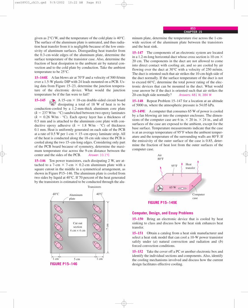
CHAPTER 15853
given as 2°C/W, and the temperature of the cold plate is 40°C.The surface of the aluminum plate is untreated, and thus radia-tion heat transfer from it is negligible because of the low emis-sivity of aluminum surfaces. Disregarding heat transfer fromthe 0.3-cm-wide edges of the aluminum plate, determine thesurface temperature of the transistor case. Also, determine thefraction of heat dissipation to the ambient air by natural con-vection and to the cold plate by conduction. Take the ambienttemperature to be 25°C.
15–144E A fan blows air at 70°F and a velocity of 500 ft/minover a 1.5-W plastic DIP with 24 leads mounted on a PCB. Us-ing data from Figure 15–23, determine the junction tempera-ture of the electronic device. What would the junctiontemperature be if the fan were to fail?
15–145 A 15–cm � 18-cm double-sided circuit boarddissipating a total of 18 W of heat is to be
conduction-cooled by a 1.2-mm-thick aluminum core plate(k � 237 W/m · °C) sandwiched between two epoxy laminates(k � 0.26 W/m · °C). Each epoxy layer has a thickness of0.5 mm and is attached to the aluminum core plate with con-ductive epoxy adhesive (k � 1.8 W/m · °C) of thickness0.1 mm. Heat is uniformly generated on each side of the PCBat a rate of 0.5 W per 1-cm � 15–cm epoxy laminate strip. Allof the heat is conducted along the 18-cm side since the PCB iscooled along the two 15–cm-long edges. Considering only partof the PCB board because of symmetry, determine the maxi-mum temperature rise across the 9-cm distance between thecenter and the sides of the PCB. Answer: 10.1°C
15–146 Ten power transistors, each dissipating 2 W, are at-tached to a 7-cm � 7-cm � 0.2-cm aluminum plate with asquare cutout in the middle in a symmetrical arrangement, asshown in Figure P15–146. The aluminum plate is cooled fromtwo sides by liquid at 40°C. If 70 percent of the heat generatedby the transistors is estimated to be conducted through the alu-
minum plate, determine the temperature rise across the 1-cm-wide section of the aluminum plate between the transistorsand the heat sink.
15–147 The components of an electronic system are locatedin a 1.2-m-long horizontal duct whose cross section is 10 cm �20 cm. The components in the duct are not allowed to comeinto direct contact with cooling air, and so are cooled by airflowing over the duct at 30°C with a velocity of 250 m/min.The duct is oriented such that air strikes the 10-cm-high side ofthe duct normally. If the surface temperature of the duct is notto exceed 60°C, determine the total power rating of the elec-tronic devices that can be mounted in the duct. What wouldyour answer be if the duct is oriented such that air strikes the20-cm-high side normally? Answers: 481 W, 384 W
15–148 Repeat Problem 15–147 for a location at an altitudeof 5000 m, where the atmospheric pressure is 54.05 kPa.
15–149E A computer that consumes 65 W of power is cooledby a fan blowing air into the computer enclosure. The dimen-sions of the computer case are 6 in. � 20 in. � 24 in., and allsurfaces of the case are exposed to the ambient, except for thebase surface. Temperature measurements indicate that the caseis at an average temperature of 95°F when the ambient temper-ature and the temperature of the surrounding walls are 80°F. Ifthe emissivity of the outer surface of the case is 0.85, deter-mine the fraction of heat lost from the outer surfaces of thecomputer case.
Computer, Design, and Essay Problems
15–150 Bring an electronic device that is cooled by heatsinking to class and discuss how the heat sink enhances heattransfer.
15–151 Obtain a catalog from a heat sink manufacturer andselect a heat sink model that can cool a 10-W power transistorsafely under (a) natural convection and radiation and (b)forced convection conditions.
15–152 Take the cover off a PC or another electronic box andidentify the individual sections and components. Also, identifythe cooling mechanisms involved and discuss how the currentdesign facilitates effective cooling.
Aluminumplate
40°C40°C
5 cm 1 cm1 cm
7 cm
Cut outsection
4 cm × 4 cm
Transistors
FIGURE P15–146
Computercase
Heattransfer
95°F
Air80°F
65 W
FIGURE P15–149E
cen58933_ch15.qxd 9/9/2002 10:22 AM Page 853

cen58933_ch15.qxd 9/9/2002 10:22 AM Page 854