cooling slope casting to obtain thixotropic feedstock i
TRANSCRIPT

Cooling Slope Casting to Obtain Thixotropic Feedstock I: Observations with a Transparent Analogue E. CARDOSO LEGORETTA Universidad Autónoma del Estado de Hidalgo, Centro de Investigaciones en Materiales y Metalurgia, Cuidad Universitaria, Carretera Pachuca-Tulancingo Km. 4.5, Pachuca, Hidalgo, México Department of Engineering Materials, University of Sheffield, Sir Robert Hadfield Building, Mappin Street, Sheffield S1 3JD, UK H. V. ATKINSON Department of Engineering, University of Leicester, University Road, Leicester LE1 7RH, UK E-mail: [email protected] H. JONES Department of Engineering Materials, University of Sheffield, Sir Robert Hadfield Building, Mappin Street, Sheffield S1 3JD, UK

Abstract New Rheocasting (the NRC process) is a recently developed semisolid processing route. There are two versions of this route. In one, molten alloy is poured directly into a tilted mould and through careful temperature control during cooling a spheroidal semisolid microstructure is achieved, before the material in the mould is upended into a shot sleeve and hence forced into a die. Alternatively, the molten alloy is poured onto a cooling slope and thence into a mould before processing. The aim of the work described in this paper, and its companion, was to develop understanding of the microstructural development during the initial stages of this process i.e. in the mould before processing and with the cooling slope/mould combination. In this first paper, an analogue system based on aqueous ammonium chloride has been used to visualise what happens when an alloy is poured into a tilted mould with a chill wall. In the companion paper, the results for pouring A356 aluminium alloy directly into a mould, and also via a cooling slope into a mould are presented. Keywords Cooling slope; thixoforming; semisolid processing; thixotropic; transparent analogue; ammonium chloride; New Rheocasting.

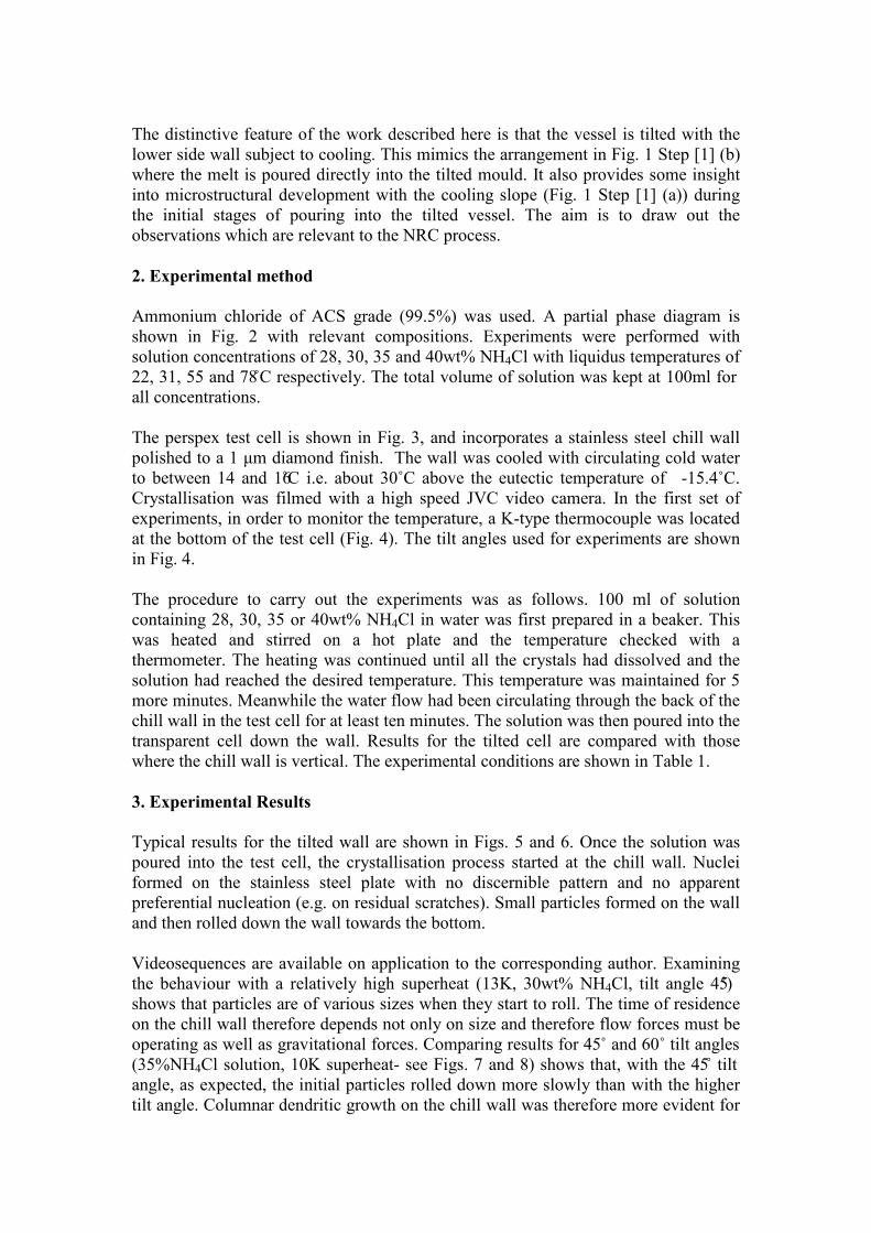
1. Introduction In the early 1970s, a group at MIT discovered that when a solidifying alloy was continuously stirred the viscosity fell to a much lower value than for the static case [1]. This was associated with the fact that, during stirring in the semisolid range, the dendritic microstructure was destroyed and the semisolid consisted of spheroids of solid in a liquid matrix. In this state, the material behaved thixotropically i.e. when sheared it flowed but when allowed to stand it thickened again; the viscosity was a function both of time at temperature and of shear rate. The behaviour was associated with the dynamic development of microscopic ‘welds’ between solid spheroids (agglomeration) and the break up of these welds under shear (disagglomeration) [2]. It became the basis of a new range of forming technologies termed collectively semisolid processing. The advantages over conventional die casting including less mould attrition, reduced porosity and hence higher part integrity, and near net shape (because there is less solidification shrinkage). A range of reviews are available [2-6]. There are various types of semisolid processing: ‘Rheocasting’ refers to the process where the alloy is cooled into the semi-solid state and injected into a die without an intermediate solidification step; ‘Rheomoulding’ is allied to polymer injection moulding, and uses either a single screw or a twin screw. ‘Thixo’ usually refers to processes where an intermediate solidification step does occur. (There are exceptions to this e.g. ‘Thixomolding®’, which is used to produce magnesium alloy components, e.g. for portable computers and cameras). ‘Thixoforming’ can cover both ‘thixocasting’, ‘thixoforging’ and an intermediate process called ‘thixoforming’. Thixocasting tends to take place with relatively high fractions of liquid and thixoforging when the fractions are lower. Thixocasting involves placing the slug of semisolid material in a shot sleeve and injecting into a die. In thixoforging, the slug of semisolid material is placed between dies and the die halves brought together around the slug. In all cases, thixotropic feedstock is required. There is a constant drive to move to the ‘Rheo’ forms of the process because this eliminates the intermediate solidification step and hence reduces cost. The non-dendritic feedstock microstructure can be obtained by a variety of means during cooling including mechanical stirring or electromagnetic stirring in the shot sleeve as in the New Semi-Solid Metal Casting process from Hitachi [7]. Alternatively, the New RheoCasting (NRC) process (Fig.1) patented by UBE [8,9] involves stimulating nucleation of solid particles. Molten alloy is poured, at a temperature slightly above the liquidus, into a tilted steel crucible. In one version of the route this pouring is via a cooling slope (Fig.1 step [1]-a) and in the other the pouring is direct (Fig.1 step [1]-b). The alloy is then partially solidified in the mould under controlled cooling conditions, which includes the application of heat to the mould using an induction heater (stage [3] in Fig. 1). This results in a spheroidal microstructure in the semisolid state. The temperature is equalized across the cross-section of the mould and the semisolid slug is then upended into the shot sleeve (hence leaving any oxide skin in the discard) and injected into the die to produce the component. There is no need for specially treated thixoformable feedstock and scrap can be readily recycled within the plant (as opposed to conventional thixoforming where the scrap must be returned to the supplier of the feedstock to be retreated e.g. with the Magneto-Hydro-Dynamic (MHD) process). Hall et al. [9] showed that the NRC route has a lower unit cost than thixoforming, due to the lower starting material cost. The principal disadvantage is that the process is relatively inflexible, with the mould size and mould induction

heating conditions very precisely related to the metered volume of alloy. Thus, the process is highly suitable for volume production of a particular component where no change in the metered volume is required. It is less suitable for producing components of varying sizes where, each time the size changed, a different mould would be required. The NRC process is gaining increasing industrial attention for high volume component production. Kaufmann et al. [10] compared NRC material with that produced by a conventional commercial thixocasting process and found a higher degree of compositional homogeneity and overall globule spheroidicity. It was also shown [11] that for high quality slugs, it is important to hold the melt close to the liquidus temperature and to quench it quickly to form many nuclei. These are distributed throughout the cup and grow in a globular fashion when two criteria are both fulfilled- the size of the nuclei and the temperature gradient in the cup must both be small. Dendritic growth is then suppressed. Uggowitzer and Kaufmann [12] argued that the nuclei are formed by ‘forced homogeneous nucleation’ due to partial quenching of the melt. This was backed up by simulation results from Zhu et al. [13]. Further detail will be given of work in the literature using a cooling slope in the Introduction to the companion paper. Here the background on analogue systems is outlined since that is the principal concern of this first paper. Semitransparent analogue systems have been used for research into metal solidification because they allow visualisation [14]. The most common analogue system used in laboratory experiments (and in the present work) is aqueous ammonium chloride (NH4Cl-H2O) with NH4Cl concentration between 25 and 40 wt%. Jackson et al. [14] studied the origin of the grains that comprise the equiaxed region in a conventional casting. When the solution was poured at temperatures close to the saturation temperature, crystals appeared throughout the liquid and swirled in a snow storm effect (‘big-bang nucleation’). They concluded that, under the interaction of heat and matter fluxes during dendritic growth, the partial remelting of dendrites is an important mechanism for producing the equiaxed region. Beckerman and Wang [15] noted that thermal and solute buoyancy forces cause convection in the melt and observed nucleation, fragmentation, recalescence, multicellular thermosolutal convection and sedimentation of NH4Cl crystals. They used a square cavity evenly cooled from the sidewalls. In the initial stages of the experiment, a large number of free crystals were observed in the upper portion of the melt. These originated from fragmentation of the crystals at the walls, which were ejected into the bulk melt by the convective flow in the residual solution. Several authors have investigated the effect of the flow behaviour on the solidification process using analogue systems [16-20]. Paradies et al [19] showed that an imposed velocity in the melt dramatically changed the rate and total amount of crystal fragmentation developed. In other work with succinonitrile/acetone [21], it was found that increasing the velocity of forced flow in a tube increases the rate of recalescence but the largest cumulative total of fragments was produced with an intermediate rate of flow. Mullis et al [22] examined the formation of spheroidal microstructures for semisolid processing with a glass vessel and made observations as a function of cooling rate. They observed large dendritic crystals at a high cooling rate, but even at the lowest cooling rate employed, no evidence of the rosette or spheroidal structures characteristic of metallic systems solidified under applied shear was found.
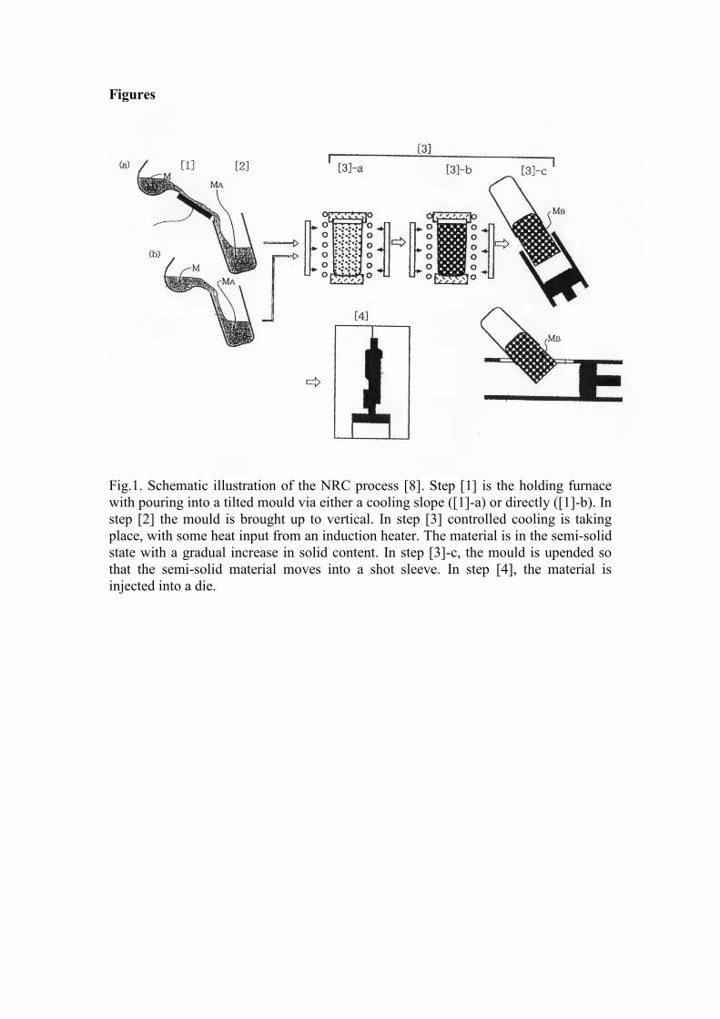
The distinctive feature of the work described here is that the vessel is tilted with the lower side wall subject to cooling. This mimics the arrangement in Fig. 1 Step [1] (b) where the melt is poured directly into the tilted mould. It also provides some insight into microstructural development with the cooling slope (Fig. 1 Step [1] (a)) during the initial stages of pouring into the tilted vessel. The aim is to draw out the observations which are relevant to the NRC process. 2. Experimental method Ammonium chloride of ACS grade (99.5%) was used. A partial phase diagram is shown in Fig. 2 with relevant compositions. Experiments were performed with solution concentrations of 28, 30, 35 and 40wt% NH4Cl with liquidus temperatures of 22, 31, 55 and 78̊ C respectively. The total volume of solution was kept at 100ml for all concentrations. The perspex test cell is shown in Fig. 3, and incorporates a stainless steel chill wall polished to a 1 μm diamond finish. The wall was cooled with circulating cold water to between 14 and 16̊C i.e. about 30˚C above the eutectic temperature of -15.4˚C. Crystallisation was filmed with a high speed JVC video camera. In the first set of experiments, in order to monitor the temperature, a K-type thermocouple was located at the bottom of the test cell (Fig. 4). The tilt angles used for experiments are shown in Fig. 4. The procedure to carry out the experiments was as follows. 100 ml of solution containing 28, 30, 35 or 40wt% NH4Cl in water was first prepared in a beaker. This was heated and stirred on a hot plate and the temperature checked with a thermometer. The heating was continued until all the crystals had dissolved and the solution had reached the desired temperature. This temperature was maintained for 5 more minutes. Meanwhile the water flow had been circulating through the back of the chill wall in the test cell for at least ten minutes. The solution was then poured into the transparent cell down the wall. Results for the tilted cell are compared with those where the chill wall is vertical. The experimental conditions are shown in Table 1. 3. Experimental Results Typical results for the tilted wall are shown in Figs. 5 and 6. Once the solution was poured into the test cell, the crystallisation process started at the chill wall. Nuclei formed on the stainless steel plate with no discernible pattern and no apparent preferential nucleation (e.g. on residual scratches). Small particles formed on the wall and then rolled down the wall towards the bottom. Videosequences are available on application to the corresponding author. Examining the behaviour with a relatively high superheat (13K, 30wt% NH4Cl, tilt angle 45̊) shows that particles are of various sizes when they start to roll. The time of residence on the chill wall therefore depends not only on size and therefore flow forces must be operating as well as gravitational forces. Comparing results for 45˚ and 60˚ tilt angles (35%NH4Cl solution, 10K superheat- see Figs. 7 and 8) shows that, with the 45̊ tilt angle, as expected, the initial particles rolled down more slowly than with the higher tilt angle. Columnar dendritic growth on the chill wall was therefore more evident for

the 45˚ results (note that this can be seen by eye but is not visible in the figure because of the video resolution). Columnar dendrites tended to develop after the first 40s or so. Low superheat leads to copious nucleation (Fig. 9) with small particles on both the chill wall and nucleating in the bulk solution. Over time these initial crystals settle and dendritic growth develops. The higher initial NH4Cl concentrations (35wt% and 40wt%) also give more copious nucleation than the lower concentrations. In experiments with a vertical chill wall (Fig. 10), the numbers of nuclei in the bulk quickly increase in the first stages. Some of these appear to have originated in the bulk and some from fragmentation of crystals at the wall. Crystals tend to congregate in the upper portion of the melt during the first five minutes and then descend slowly, becoming entrained in the thermally driven downward flow of fluid adjacent to the crystallisation front. Some of the crystals become lodged in the liquidus front of the mushy zone (Fig. 10(b)). Crystals rotating in the flow in the bulk tend to show a symmetric dendritic morphology whilst those attached to the cooling slope are columnar. Comparing results for the vertical chill wall with those for the tilted wall, the cooling wall is more effective in promoting crystallisation in the latter case, the high concentration of fine crystals formed during initial contact with the mould wall becoming redistributed through the liquid. This effect is counteracted if the superheat is too high (say 15K) because the crystallites tend to redissolve when they move out into the bulk solution. 4. Discussion The essential aim of the NRC process is to obtain a spheroidal morphology uniformly across the casting, albeit after a process of equilibration (Fig. 1 steps [3]-a and [3]-b) where heat is transferred whilst the mould is being held in the semi-solid state in a vertical position. Here the experiments focus on the initial stages of the process, rather than the equilibration (i.e. Fig. 1 stages [1] and [2]). In addition, in the aqueous ammonium chloride system there is a substantial density difference between the crystals and the liquid, giving rise to settling, which does not exist to the same extent for solidification in aluminium alloys. Given these provisos, the following points can be made: 1) The higher initial NH4Cl concentrations (35wt% and 40wt%) and lower
superheats (1-5K) tend to give more copious nucleation, as would be expected (schematically shown in Fig. 11(a)). Low superheat enhances crystal survival, partly through a reduction in thermal convection. The superheat results are significant for the NRC process. Lower initial concentrations and higher superheats tend to produce gradual columnar dendritic solidification (schematically shown in Fig. 11(b) and (c)).
2) Crystals nucleating on the chill wall are observed to roll down the wall after a certain residence time. This raises the interesting issue as to the importance of the surface finish on the chill wall. This should not occur to the same extent in the NRC case where there is little density difference between the crystal and the liquid. However, the surface finish of the chilling surface will play an important role in determining how easy it is for crystals to become detached from the chill wall and incorporated into the fluid flow.

3) Increasing tilt angle from 45̊ to 60˚ tends to increase the speed at which particles roll down the wall and therefore enhance the possibility of equiaxed formation rather than columnar dendritic growth. This again has important implications for the NRC process, either in terms of the tilt of the mould (for direct pouring) or the tilt of the cooling slope. However, there will be an optimum angle for enhancing equiaxed formation beyond which the chill wall is not able to play as significant a role in nucleation.
The observations on the morphology of the crystals in the bulk are consistent with work by Appolaire et al. [25] who showed that crystals rotating in the flow tend to be symmetric, whilst those which are not become asymmetric. In a companion paper [26], the results for pouring A356 aluminium alloy directly into a mould, and also via a cooling slope into a mould, are presented. The observations with the transparent analogue provide insight into the phenomena which are occurring. Summary and Concluding Remarks The aim here was to visualise the initial stages of the solidification processes in New Rheocasting (NRC) with aluminium alloys through the use of a transparent aqueous ammonium chloride analogue. The ammonium chloride has been poured into a perspex cell with one wall chilled. This mimics the mould and the cooling slope in the NRC process, although there is a substantial density difference between the crystals and the remaining liquid in the ammonium chloride system which leads to some settling which does not occur with aluminium alloys. Higher initial NH4Cl concentrations (35wt% and 40wt%) and lower superheats (1-5K) tend to give more copious nucleation, as would be expected. The superheat results are significant for the NRC process. Crystals nucleating on the chill wall roll down the wall after a certain residence time. The surface finish of the chill wall (cooling slope) may therefore be important in determining how easy it is for crystals to become detached from the chill wall and incorporated into the fluid flow. Increasing the tilt angle (up to a point beyond which the chill wall is not able to play a full role in enhancing nucleation) tends to increase the speed at which particles roll down the wall and therefore to enhance the possibility of equiaxed formation rather than columnar dendritic growth. A companion paper gives results for pouring A356 aluminium alloy directly into a mould and also into a mould via a cooling sliope. Acknowledgements ECL would like to acknowledge financial support provided by CONACyt and SEP and also the Universidad Autónoma del Estado de Hidalgo for support. The authors are grateful to the Department of Engineering Materials at the University of Sheffield for the provision of laboratory facilities. HVA would like to acknowledge the University of Leicester for sabbatical leave.

References 1. Spencer DB, Mehrabian R, Flemings MC (1972) Metall Trans 3:1925 2. Flemings MC (1991) Metall Trans A22:957 3. Kirkwood DH (1994) Int Mater Rev 39:173 4. Figuredo A de (ed) (2001) Science and Technology of Semi-Solid Processing.
North American Die Casting Association, Rosemont, IL 5. Fan Z (2002) Int Mater Rev 47:49 6. Atkinson HV (2005) Prog Mater Sci 50:341 7. Kaneuchi T, Shibata R, Ozawa M (2002) In: Tsutsui Y, Kiuchi M, Ichikawa K
(eds) Proceedings of the 7th International Conference on Advanced Semi-Solid Processing of Alloys and Composites, Tsukuba, Japan, 2002. National Institute of Advanced Science and Technology and the Japan Society for Technology of Plasticity, p.145.
8. Mitsuru A, Hiroto S, Yasunori H, Tatsuo S, Satoru S, Atsushi Y (1996) Method and Apparatus for Shaping Semisolid metals, UBE Industries Limited, Patent EP 0745694 A1
9. Hall K, Kaufmann H, Mundl A (2000) Chiarmetta GL, Rosso M (eds) Proceedings of the 6th International Conference on Semi-Solid Processing of Alloys and Composites, Turin, Italy, 2000. Edimet Spa, Brescia, Italy, p.23
10. Kaufmann H, Ranshofen H, Wabusseg H, Uggowitzer PJ (2000) Aluminium 76:70
11. Kaufmann H, Mundl A, Uggowitzer PJ, Potzinger R, Ishibashi N (2002) Die Casting Engineer, July 2002:16
12. Uggowitzer PJ, Kaufmann H (2004) Steel Research International 75:525 13. Zhu MF, Kim JM, Hong CP (2001) ISIJ Intern 41:992. 14. Jackson KA, Hunt JD (1965) Acta Metallurgica 13:1212 15. Beckerman C, Wang CY (1996) Metallurgical and Materials Transactions
27A:2784 16. Hansen G, Hellawell A, Lu SZ, Steube RS (1996) Metallurgical and Materials
Transactions 27A:569 17. Christenson MS, Incropera FP (1989) Int J Heat Mass Transfer 32:47 18. Prescott PJ, Incropera FJ (1996) Transport Phenomena in Materials Processing
28:231 19. Paradies CJ, Kim GT, Glicksman ME, Smith RN (1993) In: Piwonka TS,
Voller V, Katgerman L (eds) Proc Int Cong Modelling of Casting, Welding and Advanced Solidification Processes VI, TMS, p. 309-316
20. Chen F (2001) Stability Analysis on Convection in Directional Solidification of Binary Solutions, Proc National Science Council, ROCA, 25, No. 2:71
21. Paradies CJ, Smith RN, Glicksman ME (1997) Metallurgical and Materials Transactions 28A:875
22. Mullis AM, Battersby SE, Fletcher HL (1998) Scripta Mater 39:147 23. Kaneko K, Koyaguchi T (2000) J Vulcanology and Geothermal Research 96:
161 24. Wang GX, Yao C, Chung BTF (1999) Proc ASME Heat Transfer Division,
364-2:281 25. Appolaire B, Albert V, Combeau H, Lesoult G (1998) Acta Mater 46:5851 26. Cardoso Legoretta E, Atkinson HV, Jones H, submitted to Journal of Materials
Science.

Tables Experiment Number
Solution Concentration (NH4Cl wt%)
Pouring Temperature oC
Tilt angle α
1 28 36 60o 2 28 36 45o 3 28 28 45o 4 30 54 45o 5 30 49 45o 6 30 44 45o 7 30 39 60o 8 35 70 60o 9 35 65 45o 10 35 60 60o 11 40 100 45o 12 40 90 60o 13 30 39 90 o 14 35 56 90 o 15 35 60 90 o 16 35 70 90 o 17 35 65 60 o 18 35 65 45 o 19 40 90 60 o 20 40 100 45 o Table 1. Conditions for the experiments with NH4Cl-H2O.

Figure Captions Fig.1. Schematic illustration of the NRC process [8]. Step [1] is the holding furnace with pouring into a tilted mould via either a cooling slope ([1]-a) or directly ([1]-b). In step [2] the mould is brought up to vertical. In step [3] controlled cooling is taking place, with some heat input from an induction heater. The material is in the semi-solid state with a gradual increase in solid content. In step [3]-c, the mould is upended so that the semi-solid material moves into a shot sleeve. In step [4], the material is injected into a die. Fig. 2. H2O-NH4Cl phase diagram. Shaded region is the composition range of interest in the present work (adapted from [23]). Fig. 3. Perspex cell used for analogue studies with the NH4Cl-H2O system. a) 3D representation, b) Cross section of the test cell. Fig. 4 Set-up for the analogue system experiments Fig. 5 Initial growth of the NH4Cl crystals on the cooling wall at 45o tilt, a) 10 s of the process, 35 % NH4Cl. Superheat 10 K and b) 30 s of the process, 28% NH4Cl. Superheat 18 K. Fig. 6 Initial growth of the NH4Cl crystals on the cooling wall, 30% NH4Cl, superheat 10 K. a) 60o tilt, b) 45o tilt. Fig. 7. Nucleation and growth from the ammonium chloride solution on the cooling wall (35wt% NH4Cl poured at 65oC, superheat 10 K, tilt angle α=45o). Fig. 8. Nucleation and growth from the ammonium chloride solution on the cooling wall (35wt% NH4Cl poured at 65oC, superheat 10 K, tilt angle α=60o). Fig. 9. Copious nucleation in the NH4Cl-H2O system (28%wt NH4Cl, superheat 6 K, tilt angle α=45o).
Fig. 10 Columnar growth and mushy equiaxed crystal bed at a) the beginning of the process and b) middle of the experiment showing columnar and equiaxed NH4Cl crystals. (35wt%NH4Cl, superheat 5 K, tilt angle α=90o).
Fig. 11. a) Equiaxed solidification due to bulk nucleation in the solution and heterogeneous surface nucleation; b) Columnar dendritic solidification, c) Schematic diagram of phenomena in the early stage of crystallization of the ammonium chloride solution. (a) and (b) adapted from [24].


Figures
Fig.1. Schematic illustration of the NRC process [8]. Step [1] is the holding furnace with pouring into a tilted mould via either a cooling slope ([1]-a) or directly ([1]-b). In step [2] the mould is brought up to vertical. In step [3] controlled cooling is taking place, with some heat input from an induction heater. The material is in the semi-solid state with a gradual increase in solid content. In step [3]-c, the mould is upended so that the semi-solid material moves into a shot sleeve. In step [4], the material is injected into a die.

Fig. 2. H2O-NH4Cl phase diagram. Shaded region is the composition range of interest in the present work (adapted from [23]).

Fig. 3. Perspex cell used for analogue studies with the NH4Cl-H2O system. a) 3D representation, b) Cross section of the test cell.
(b)
Stainless Steel Chill Wall
4 cm
4 cm
8.5 cm
Coolant in
Coolant out
Perspex Cell
(a)
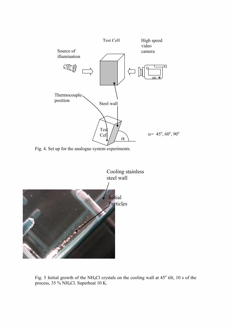
Fig. 4. Set up for the analogue system experiments.
(b) Fig. 5 Initial growth of the NH4Cl crystals on the cooling wall at 45o tilt, 10 s of the process, 35 % NH4Cl. Superheat 10 K.
α= 45o, 60o, 90o α
Test Cell
Test Cell
Source of illumination
High speed video camera
Steel wall
Thermocouple position
Initial Particles
Cooling stainless steel wall
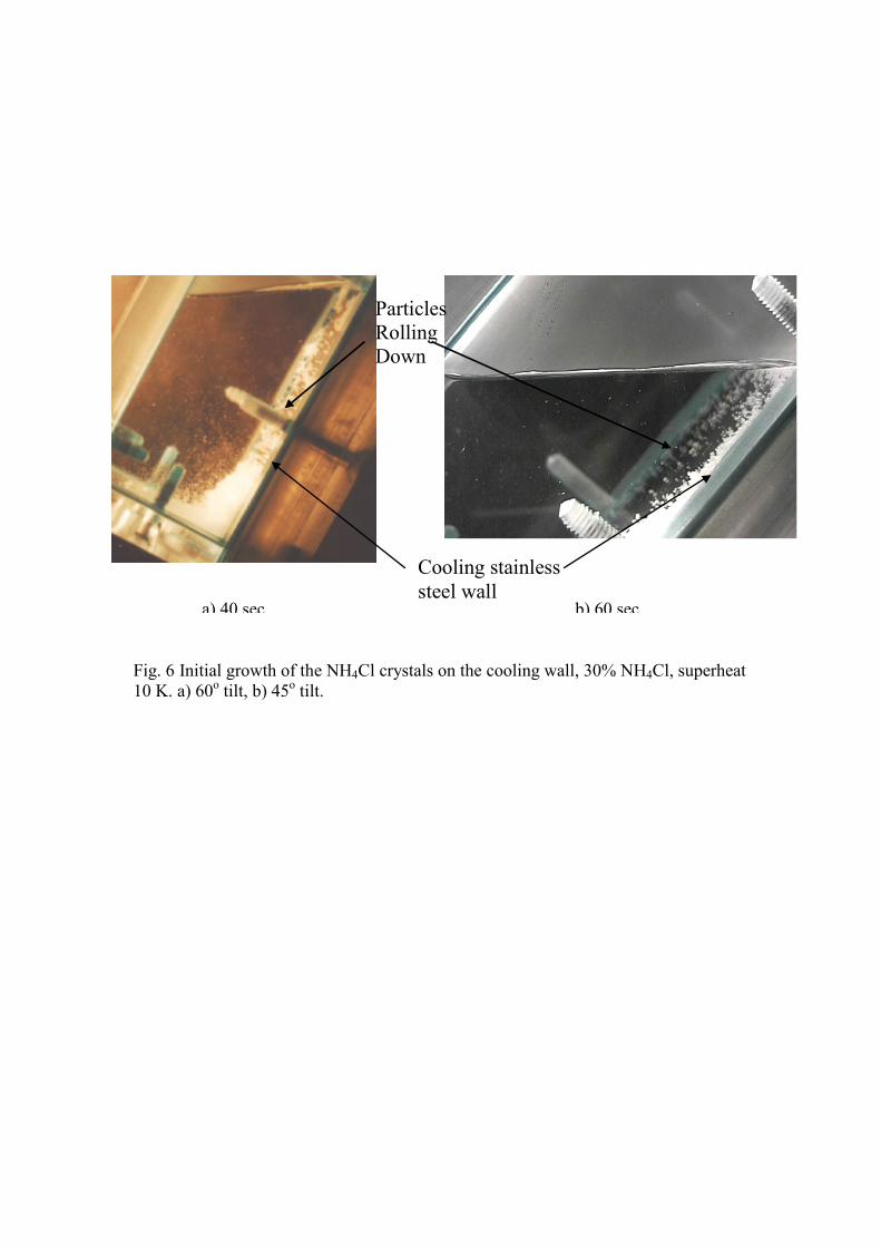
Fig. 6 Initial growth of the NH4Cl crystals on the cooling wall, 30% NH4Cl, superheat 10 K. a) 60o tilt, b) 45o tilt.
Particles Rolling Down
a) 40 sec b) 60 sec
Cooling stainless steel wall

14s 13.5s 14.5s 15s
15.5s 16s 16.5s 17s
22s 23s 24s 28s
33s 38s 43s 46s
430s 76s 83s 143s
Fig. 7. Nucleation and growth from the ammonium chloride solution on the cooling wall (35wt% NH4Cl poured at 65oC, superheat 10 K, tilt angle α=45o).

Fig. 8. Nucleation and growth from the ammonium chloride solution on the cooling wall (35wt% NH4Cl poured at 65oC, superheat 10 K, tilt angle α=60o).

Fig. 9. Copious nucleation in the NH4Cl-H2O system (28%wt NH4Cl, superheat 6 K, tilt angle α=45o).
1s 30s
120s 220s 160s
60s 90s
Columnar growth
Equiaxed crystals in the bulk solution
NH4Cl crystals settle down

Fig.10. Columnar growth, and mushy equiaxed crystal bed at a) the beginning of the process b) middle of the experiment showing columnar and equiaxed NH4Cl crystals. (35wt%NH4Cl, superheat 5 K, tilt angle α=90o).
b)
Small particles in the bulk solution
Columnar Dendritic Growth
EquiaxedCrystal Bed
a)
Particles lodged in liquidus front
Particles falling down

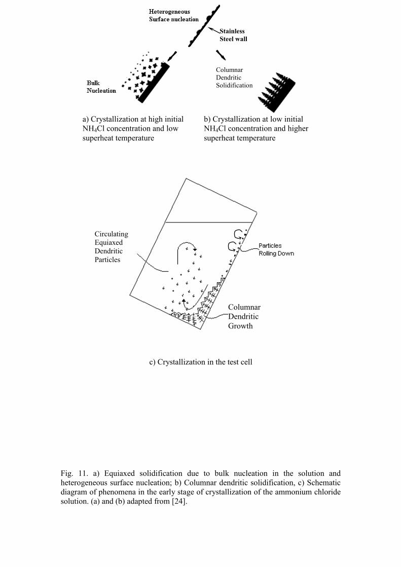
Fig. 11. a) Equiaxed solidification due to bulk nucleation in the solution and heterogeneous surface nucleation; b) Columnar dendritic solidification, c) Schematic diagram of phenomena in the early stage of crystallization of the ammonium chloride solution. (a) and (b) adapted from [24].
Stainless Steel wall
c) Crystallization in the test cell
Columnar Dendritic Solidification
Circulating Equiaxed Dendritic Particles
Columnar Dendritic Growth
b) Crystallization at low initial NH4Cl concentration and higher superheat temperature
a) Crystallization at high initial NH4Cl concentration and low superheat temperature
