cooling systems - boat parts, marine engine - · pdf file6a-0 seawater cooling systems...
TRANSCRIPT

624728
A
COOLING SYSTEMS
SEAWATER COOLING SYSTEMS

6A-0 SEAWATER COOLING SYSTEMS 90-806535940 893
Table of ContentsPage
Specifications 6A-1. . . . . . . . . . . . . . . . . . . . . . . . . . MCM 3.0L/3.0LX 6A-1. . . . . . . . . . . . . . . . . . . .
Torque Specifications 6A-1. . . . . . . . . . . . . . Tools/Lubricants/Sealants 6A-1. . . . . . . . . . Specifications 6A-1. . . . . . . . . . . . . . . . . . . .
MCM 4.3L/4.3LX 6A-2. . . . . . . . . . . . . . . . . . . . Torque Specifications 6A-2. . . . . . . . . . . . . . Tools/Lubricants/Sealants 6A-2. . . . . . . . . . Specifications 6A-2. . . . . . . . . . . . . . . . . . . .
305/5.0L/350/5.7L/454/7.4L/502/8.2L 6A-3. . . Torque Specifications 6A-3. . . . . . . . . . . . . . Tools/Lubricants/Sealants 6A-3. . . . . . . . . . Specifications 6A-4. . . . . . . . . . . . . . . . . . . .
Identification 6A-4. . . . . . . . . . . . . . . . . . . . . . . . . . . 3.0L/305/5.0L/350/5.7L 6A-4. . . . . . . . . . . . . . . 454/7.4L/502/8.2L 6A-4. . . . . . . . . . . . . . . . . . .
Seawater Pickups 6A-4. . . . . . . . . . . . . . . . . . . . . . Thru-Hull Mounted 6A-4. . . . . . . . . . . . . . . . . . . Transom Mounted 6A-5. . . . . . . . . . . . . . . . . . .
Sea Strainer 6A-5. . . . . . . . . . . . . . . . . . . . . . . . . . . Seawater Pickup Pump Output Test 6A-5. . . . . .
Engines with Stern Drive Seawater PickupPump 6A-7. . . . . . . . . . . . . . . . . . . . . . . . . . . . . .
Thermostat 6A-8. . . . . . . . . . . . . . . . . . . . . . . . . . . . Testing 6A-8. . . . . . . . . . . . . . . . . . . . . . . . . . . . . Belt Driven Seawater Pickup Pump(All ModelsExcept 454/7.4L/502/8.2L) 6A-10. . . . . . . . . . . . Seawater Pump 454/7.4L/502/8.2L 6A-10. . . .
Water Flow Diagrams And Draining Locations 6A-11. . . . . . . . . . . . . . . . . . . . . . . . . . . . .
MCM 3.0L/3.0LX 6A-11. . . . . . . . . . . . . . . . . . . . MCM Models 4.3L/4.3LX 6A-12. . . . . . . . . . . . . MCM 305/5.0L/350/5.7L 6A-13. . . . . . . . . . . . . . MCM Bravo 305/5.0L/350/5.7L 6A-14. . . . . . . . MCM 7.4L/454 Magnum 6A-15. . . . . . . . . . . . . . MCM 502 EFI Magnum 6A-16. . . . . . . . . . . . . . . MIE 305/5.0L/350/5.7L 6A-17. . . . . . . . . . . . . . . MIE 7.4L/8.2L 6A-18. . . . . . . . . . . . . . . . . . . . . . .
Stern Drive Draining Locations 6A-19. . . . . . . . . . . Auxiliary Hot Water Heater Connections 6A-20. . .
6A - SEAWATER COOLING SYSTEMS

SEAWATER COOLING SYSTEMS - 6A-190-806535940 893
Specifications
Units of MeasurementsIn. (mm)
Qts. (Litres)
MCM 3.0L/3.0LX
TORQUE SPECIFICATIONS
Fastener Location lb. ft. (N ⋅m)
Drain Plugs (See Note 1) Securely
Petcocks Securely
Power Steering Pump Bracket 30(41)
Pulleys Securely
Hose Clamps Securely
Thermostat Cover 30(41)
Thermostat Housing 30(41)
Throttle Lever Nut to Throttle Body Shaft Securely
Water Circulating Pump 30(41)
Water Temperature Sender 20(27)
Water Temperature Switch Securely
Note: 1 Coat threads with Quicksilver Perfect Seal before installing.TOOLS/LUBRICANTS/SEALANTS
Part Number Description
91-37241 Universal Plate Puller
92-32609-1 Quicksilver Loctite (Type A or 271)
92-34227-1 Quicksilver Perfect Seal
92-86154A1 Quicksilver 2-C-4 Marine Lubricant
92-13872A1 Quicksilver Special Lubricant 101
73971A2 Flush Device
Obtain Locally Shell Alvania No. 2
SPECIFICATIONS
Cooling System Capacity 9(8.5)
Thermostat (Brass) 143°F(62°C)

6A-2 SEAWATER COOLING SYSTEMS 90-806535940 893
MCM 4.3L/4.3LX
TORQUE SPECIFICATIONS
Fastener Location lb. ft. (N ⋅m) lb. in. (N ⋅m)
Alternator Brace to Alternator 192(28)
Alternator Brace to Block 30(41)
Alternator to Mounting Bracket
Alternator Mounting Bracket 30(41)
Drain Plugs (See Note) Securely
Hose Clamps Securely
Petcocks Securely
Power Steering Pump Brace toBlock
30(41)
Power Steering Pump Bracket 30(41)
Pulleys Securely
Thermostat Cover 30(41)
Thermostat Housing 30(41)
Water Circulating Pump 30(41)
Water Temperature Sender 20(27)
Note: Coat threads with Quicksilver Perfect Seal before installing.TOOLS/LUBRICANTS/SEALANTS
Part Number Description
92-34227-1 Quicksilver Perfect Seal
73971A2 Quicksilver Flushing Attachment
92-25711--2 Quicksilver Liquid Neoprene
Obtain LocallyLoctite Pipe Sealant with Teflon
Obtain Locally Marine Caulking
SPECIFICATIONS
Cooling System Capacity 15(14)
Thermostat (Type) Stainless 140°F(60°C)Thermostat (Type) Stainless 140°F(60°C)Thermostat (Type) Stainless 140 F(60 C)

SEAWATER COOLING SYSTEMS - 6A-390-806535940 893
305/5.0L/350/5.7L/454/7.4L/502/8.2L
TORQUE SPECIFICATIONS
Fastener Location lb. ft. (N ⋅m) lb. in. (N ⋅m)
Alternator Brace to Alternator 192(28)
Alternator Brace to Block 30(41)
Alternator to Mounting Bracket
Alternator Mounting Bracket 30(41)
Drain Plugs (See Note) Securely
Hose Clamps Securely
Petcocks Securely
Power Steering Pump Brace toBlock
30(41)
Power Steering Pump Bracket 30(41)
Pulleys Securely
Seawater Pump Brace 30(41)
Seawater Pump Bracket to Block 30(41)
Seawater Pump Clamping Screwon Cast Bracket
20(17)
Seawater Pump Cover 120(14)
Thermostat Cover 30(41)
Thermostat Housing 30(41)
Water Circulating Pump 30(41)
Water Temperature Sender 20(27)
Note: Coat threads with Quicksilver Perfect Seal before installing.TOOLS/LUBRICANTS/SEALANTS
Part Number Description
92-34227-1 Quicksilver Perfect Seal
73971A2 Quicksilver Flushing Attachment
91-37241 Universal Puller Plate
92-32609-1 Quicksilver Loctite Type A
73971A2 Quicksilver Flushing Attachment
J-25034 Pulley Puller (Kent-Moore)
92-25711 Quicksilver Liquid Neoprene
92-13872A1 Quicksilver Special Lubricant
92-816026A Quicksilver High Performance Gear Lube
Obtain LocallySilicone Sealant or Equivalent
Obtain Locally Shell Alvania No. 2 Grease
Loctite Pipe Sealant with Teflon

6A-4 SEAWATER COOLING SYSTEMS 90-806535940 893
SPECIFICATIONS
Cooling System Capacity 15(14.1)
ThermostatAll Models Except EFI 143F°(62°C)
EFI 160F°(71°C)
Identification
4.3L/305/5.0L/5.7L/350 Magnum
72532b
c
d a
e
a - Seawater Pumpb - Bracketc - Pulleyd - Inlet Hosee - Outlet Hose
7.4L/8.2L/454/502 Magnum
b
70346
cd
a
a - Fuel Pumpb - Seawater Pumpc - Vent Screwd - Drain Screw (Lubricant)
Seawater PickupsNOTICE
Refer to manufacturer’s instructions for in-formation on removal and installation of otherthan Quicksilver Seawater Pickups.
IMPORTANT: Seal the inside edges of any holemade through the hull with a suitable sealant toprevent water absorption and deterioration.
Thru-Hull Mounted(Quicksilver Part Number: 68670A2)
72639
b
c
d
a
a - Seawater Pickup (Quicksilver Part Number 68670A2)b - Seawater Inlet Slots (MUST Face Forward - Parallel with
Water Flowc - Mounting Screw Holes (if So Designed)d - Nut
MIE Configuration

SEAWATER COOLING SYSTEMS - 6A-590-806535940 893
Transom Mounted
72640
bc
de
f
gh
i
J
a
a - Hose Nippleb - Nuts (4)c - Gasket - Between
Pickup and Transomd - O-Ring (4)e - Washer (4)f - Screw (4)g - Plastic Plugh - Pickupi - Screenj - Screw (2)
Sea Strainerb
c
d
e
f
g
h
a
72673
a - Screws and Washersb - Cover c - Glassd - O-Ringe - Strainerf - Housingg - Drain Plug and Sealing Washerh - Gasket
Seawater Pickup PumpOutput TestIf an overheating problem exists, use this test to de-termine if a sufficient amount of water is being sup-plied to cool engine.
IMPORTANT: The following information shouldbe observed before proceeding with test:
• BOAT MUST BE IN THE WATER FOR THISTEST. This test CANNOT BE performed with aflush-test device and water hose.
• The ability of this test to detect a problem isgreatly dependent upon the accuracy inwhich it is performed. An error in setting theengine RPM, timing the test or measuring thewater output will affect the overall accuracy ofthe test and may produce misleading results.To help ensure accurate results, a shoptachometer with an error of less than 5%should be used. The boat tachometer definite-ly should not be used as its accuracy is ques-tionable. A stop watch should be used to timethe duration of the test to help ensure that theaccuracy is maintained within one second. An8 qt. (7.6 L) or larger capacity container cali-brated in 1/4 qt. (250 cu. cm.) incrementsshould be used to measure water output.
• Due to the manner in which this test is per-formed, it may not be possible to detect a mar-ginal condition or a high-speed water pumpoutput problem.
6A-6 SEAWATER COOLING SYSTEMS 90-806535940 893
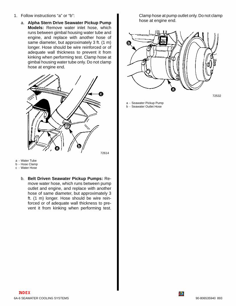
1. Follow instructions “a” or “b”:
a. Alpha Stern Drive Seawater Pickup PumpModels: Remove water inlet hose, whichruns between gimbal housing water tube andengine, and replace with another hose ofsame diameter, but approximately 3 ft. (1 m)longer. Hose should be wire reinforced or ofadequate wall thickness to prevent it fromkinking when performing test. Clamp hose atgimbal housing water tube only. Do not clamphose at engine end.
72614
a - Water Tubeb - Hose Clampc - Water Hose
b
c
a
b. Belt Driven Seawater Pickup Pumps: Re-move water hose, which runs between pumpoutlet and engine, and replace with anotherhose of same diameter, but approximately 3ft. (1 m) longer. Hose should be wire rein-forced or of adequate wall thickness to pre-vent it from kinking when performing test.
Clamp hose at pump outlet only. Do not clamphose at engine end.
72532
a - Seawater Pickup Pumpb - Seawater Outlet Hose
b
a

SEAWATER COOLING SYSTEMS - 6A-790-806535940 893
2. Repeat test four times to check repeatability of re-sults.
Alpha Stern Drive Pump Outputfor 15 Second Period
Drive Unit Gear RatioMinimum Quantity U.S. Qts. (L)
1.98:1 3.0 (2.8)
1.84:1 3.3 (3.1)
1.65:1 3.6 (3.4)
1.50:1 4.0 (3.8)
1.32:1 4.5 (4.3)
Belt Driven Pump Outputfor 15 Second Period
7.5 U.S. Qt. (7.1 L) Minimum
Engines with Stern Drive SeawaterPickup Pump
! CAUTIONTo prevent engine or stern drive unit damage DONOT run engine or drive unit without water beingsupplied to water intake openings on gear hous-ing.
Note:If flushing cooling system with boat in water,raise drive unit to trailer position, install flushing at-tachment and lower drive unit to full IN/DOWN posi-tion.
1. Install Quicksilver Flushing Attachment (or equiv-alent) over water intake openings in gear hous-ing.
2. Connect hose between flushing attachment andwater tap.
72672
a - Quicksilver Flushing Attachmentb - Garden Hose
b
a
3. With drive unit in normal operating position, par-tially open water tap (about 1/2 maximum) and al-low cooling system to fill completely. Cooling sys-tem is full when water is discharged through thepropeller. Do not use full tap water pressure.
4. Place remote control in NEUTRAL, idle speedposition and start engine. Operate engine at idlespeed, in NEUTRAL, for about 10 minutes, or un-til discharge water is clear. Watch temperaturegauge on instrument panel to ensure that enginedoes not overheat.
5. Stop engine. Shut off tap water and remove flush-ing attachment.

6A-8 SEAWATER COOLING SYSTEMS 90-806535940 893
Thermostat
72589
b
c
d
a
e
f
a - Coverb - Gasketc - Spacerd - Thermostate - O-Ringf - Housing
All Engines Except 454/502 Magnum EFI/BravoThree
71758
b
c
d
a
e
a - Housingb - O-Ringc - Thermostat (Stainless
Steel Style)d - Spacere - Gasket
454/502 Magnum EFIBravo Three Engines
Testing1. Clean thermostat in soap and water to remove
any deposits or debris.
2. Inspect thermostat for corrosion or other visibledamage.
7180172674
a
b
a - Brass Thermostatb - Stainless Steel Thermostat

SEAWATER COOLING SYSTEMS - 6A-990-806535940 893
3. If thermostat is suspected of producing insuffi-cient engine temperature, check thermostat forleakage by holding it up to a lighted background.Light leakage around the thermostat valve indi-cates that thermostat is not closing completelyand should be replaced. (A small amount of leak-age at one or two points around the valve perime-ter is acceptable.)
72717
a - Check for Light Leakage around Perimeter of Valve
a
Brass Thermostat Shown (Stainless Similar)
4. Check opening and closing temperature of ther-mostat (using a tester similar to the one shown)as follows:
a. Fill tester to within 1 in. (25mm) of top with tapwater. Do not use distilled water.
b. Open thermostat valve and insert nylonstring. Position thermostat on string so that itwill be just below water level when sus-pended, then allow valve to close. Suspendthermostat in water.
c. Place thermometer in container and positionso that bottom of thermometer is even withbottom of thermostat. Do not allow thermom-eter to touch container.
72675
a - Thermometerb - Nylon Stringc - Thermostat (Typical)
b
c
a
IMPORTANT: When performing procedures“d”-“f,” water must be agitated thoroughly to ob-tain accurate results.
d. Plug in tester and observe temperature atwhich thermostat opens (thermostat drops offthread). Thermostat must open at specifiedtemperature stamped on thermostat.
e. Continue to heat water until a temperature25°F (14°C) above temperature specified onthermostat is obtained. Thermostat valvemust be completely open at this temperature.
f. Unplug tester and allow water to cool to a tem-perature 10°F (5°C) below specified tempera-ture on thermostat. Thermostat must be com-pletely closed at this temperature.
g. Replace a thermostat that fails to meet all ofthe preceding tests.
6A-10 SEAWATER COOLING SYSTEMS 90-806535940 893
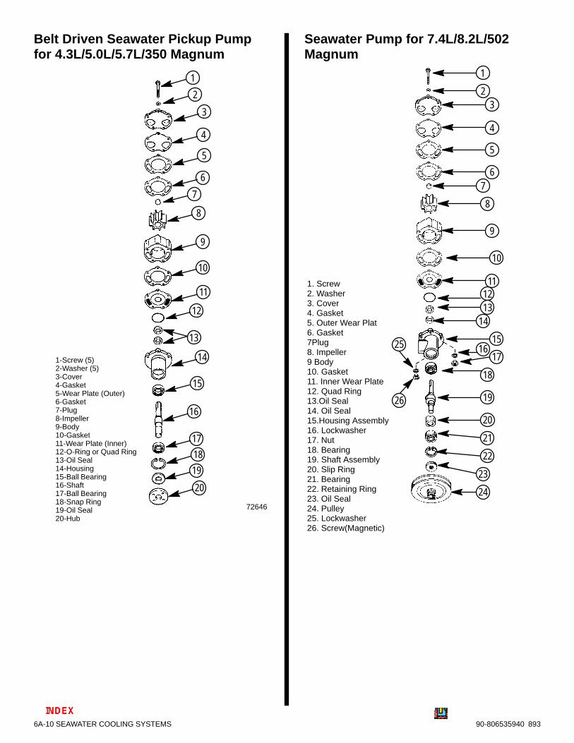
Belt Driven Seawater Pickup Pumpfor 4.3L/5.0L/5.7L/350 Magnum
72646
1
2
3
4
5
6
7
8
9
10
11
12
13
14
15
16
17
18
19
20
1-Screw (5)2-Washer (5)3-Cover4-Gasket5-Wear Plate (Outer)6-Gasket7-Plug8-Impeller9-Body10-Gasket11-Wear Plate (Inner)12-O-Ring or Quad Ring13-Oil Seal14-Housing15-Ball Bearing16-Shaft17-Ball Bearing18-Snap Ring19-Oil Seal20-Hub
Seawater Pump for 7.4L/8.2L/502Magnum
1
23
4
5
67
8
9
10
111213
14
1516
17
18
19
20
21
22
23
24
1. Screw2. Washer3. Cover4. Gasket5. Outer Wear Plat6. Gasket7Plug8. Impeller9 Body10. Gasket11. Inner Wear Plate12. Quad Ring13.Oil Seal14. Oil Seal15.Housing Assembly16. Lockwasher17. Nut18. Bearing19. Shaft Assembly20. Slip Ring21. Bearing22. Retaining Ring23. Oil Seal24. Pulley25. Lockwasher26. Screw(Magnetic)
26
25

SEAWATER COOLING SYSTEMS - 6A-1190-806535940 893
Water Flow Diagrams And Draining LocationsNOTE: Refer to Stern Drive Draining Locations following these diagrams for additional instructions on MCM (SternDrive) Power Packages.
IMPORTANT: After cooling system has been drained completely, install and tighten securely all drainplugs. Reconnect all hoses and tighten all hose clamps securely.
MCM 3.0L/3.0LX
- Remove Plugs (Repeatedly Clean Out Holes Using A Stiff Wire Until Entire System Is Drained)
a
a - Remove Hoses (Lift lower or Bend Hose to Completely Drain Hoses)
a
b
b
b
b

6A-12 SEAWATER COOLING SYSTEMS 90-806535940 893
MCM Models 4.3L/4.3LX
a - Remove Hoses(Lift lower or Bend Hose to Completely Drain Hoses)
b - Remove Plugs (Repeatedly Clean Out Holes Using A Stiff Wire Until Entire System Is Drained)
a
a
a
a
b
THERMOSTATLEGEND
COLD
WARM
22380
b

SEAWATER COOLING SYSTEMS - 6A-1390-806535940 893
MCM 305/5.0L/350/5.7L/350Magnum
22382
THERMOSTATLEGEND
COLD
WARM
22380
aa
a
a
a - Remove Hoses (Lift lower or Bend Hose to Completely Drain Hoses)
b - Remove Plugs (Repeatedly Clean Out Holes Using A Stiff Wire Until Entire System Is Drained)
b
b

6A-14 SEAWATER COOLING SYSTEMS 90-806535940 893
MCM Bravo 5.0L/5.7L
72998
THERMOSTATLEGEND
COLD
WARM
22380
a - Remove Hoses (Lift lower or Bend Hose to Completely Drain Hoses)
b - Remove Plugs (Repeatedly Clean Out Holes Using A Stiff Wire Until Entire System Is Drained)
a
a
a
a
a
b
72532
1
1 -Seawter Inlet Hose
b
1

SEAWATER COOLING SYSTEMS - 6A-1590-806535940 893
MCM 7.4/454
72692
THERMOSTATLEGEND
COLD
WARM
22380
a - Remove Hoses (Lift, lower or Bend Hose to Completely Drain Hoses)
b - Remove Plugs (Repeatedly Clean Out Holes Using A Stiff Wire Until Entire System Is Drained)
b
ba
a
a
aa
1
1 Seawater Inlet Hose

6A-16 SEAWATER COOLING SYSTEMS 90-806535940 893
MCM 502 Magnum
72973
THERMOSTATLEGEND
COLD
WARM
22380
b
a
a
a
a
a
b
a - Remove Hoses (Lift, lower or Bend Hose to Completely Drain Hoses)
b - Remove Plugs (Repeatedly Clean Out Holes Using A Stiff Wire Until Entire System Is Drained)
70346
1
1 -Sewater Inlet Hose
1

SEAWATER COOLING SYSTEMS - 6A-1790-806535940 893
MCM 502 EFI Magnum
71694
a - Remove Hoses (Lift, lower or Bend Hose to Completely Drain Hoses)
b - Remove Plugs (Repeatedly Clean Out Holes Using A Stiff Wire Until Entire System Is Drained)
b
b
a
a
a
a
a

6A-18 SEAWATER COOLING SYSTEMS 90-806535940 893
MIE 5.0L/5.7L/350 Magnum
24728
THERMOSTATLEGEND
COLD
WARM
22380
a - Remove Hoses (Lift, lower or Bend Hose to Completely Drain Hoses)
b - Remove Plugs (Repeatedly Clean Out Holes Using A Stiff Wire Until Entire System Is Drained)
a
a
a
a
a
b
72532
b
1
1 -Seawter Inlet Hose
1

SEAWATER COOLING SYSTEMS - 6A-1990-806535940 893
MIE 7.4L/8.2L
72973
THERMOSTATLEGEND
COLD
WARM
22380
b
a
a
a
a
a
b
a - Remove Hoses (Lift, lower or Bend Hose to Completely Drain Hoses)
b - Remove Plugs (Repeatedly Clean Out Holes Using A Stiff Wire Until Entire System Is Drained)
70346
1
1
1
- Seawater Inlet Hose

b
a
1
1 Seawater Inlet Pump
a - Remove Hoses (Lift lower or Bend Hose to Completely Drain Hoses)
b - Remove Plugs (Repeatedly Clean Out Holes Using A Stiff Wire Until Entire System Is Drained)
b
a
a
a
a
73372
70346
6A-20 SEAWATER COOLING SYSTEMS 90-806535940 893
MIE 454 Magnum EFI Ski

SEAWATER COOLING SYSTEMS - 6A-2190-806535940 893
Stern Drive DrainingLocations1. Follow instructions “a” or “b”:
a. On Bravo Drive Equipped Models: Insert asmall wire (repeatedly) to make sure thatspeedometer pitot tube, trim tab cavity venthole, and trim tab cavity drain passage are un-obstructed and open.
71217
a - Speedometer Pitot Tubeb - Trim Tab Cavity Vent Holec - Trim Tab Cavity Drain Passage
b
c
a
b. On Alpha Drive Equipped Models: Insert asmall wire (repeatedly) to make sure that ventholes and water drain holes and passages (asshown) are unobstructed and open.
b
c
d
a
71216
e
f
70134
a - Speedometer Pitot Tubeb - Trim Tab Cavity Vent Holec - Trim Tab Cavity Drain Passaged - Gear Housing Water Drain Hole (One Each - Port
and Starboard)e - Gear Housing Cavity Vent Holef - Gear Housing Cavity Drain Hole
cf

6A-22 SEAWATER COOLING SYSTEMS 90-806535940 893
Auxiliary Hot Water Heater Connections
72997Heater Connections on Typical MerCruiser with Standard Cooling
b
ac
a - Heater Inletb - Heater Outletc - Hole on Backside of Thermostat Housing