cooper bussmann transportation products · cooper bussmann transportation products t 1ipof t ......
TRANSCRIPT

Cooper BussmannTransportation Products

Table of Contents
Cooper Bussmann Transportation Products
Introduction to Cooper Bussmann Transportation Products 3
Conversion, Conditioning, Distribution,
Management & Controls
Power Distribution & Circuit Protection
easy ™
®
®
Mobile Vehicle Controls
Cooper Bussmann circuit protection solutions comply with major industrial standards and agency requirements such as: BS, IEC, DIN, UL, NEMA, SAE, CSA, CE, C-UL, etc. and are manufactured at facilities that
are ISO 9000 certified. This catalog is intended to present product data and provide technical information that will help the end user with design application. Cooper Bussmann reserves the right, without notice,
to change design or construction of any products and to discontinue or limit distribution of any products. Cooper Bussmann also reserves the right to change or update, without notice, any technical information
contained in this catalog. Once a product has been selected, it should be tested by the user in all possible applications. Further, Cooper Bussmann takes no responsibility for errors or omissions contained in
this catalog, or for misapplication of any Cooper Bussmann product. Extensive product information is available in the Cooper Bussmann product data sheets available online at www.cooperbussmann.com.
Printed in the USA ©2010 Cooper Bussmann
2

Cooper Bussmann Transportation Products
We’re experts on the effects of cold and heat, vibration, high moisture, harsh chemicals and transient power fluctuations. We know vehicle power and control systems from the smallest to largest platforms, and will partner with you to develop reliable products and systems.
With combined industry history and experience reaching back more than 90 years, the engineering strength and proven track record of the Cooper Bussmann®, Sure Power and OMNEX Control Systems brands provide you the ability to accelerate product development in “smart” systems and create innovative, industry-leading solutions. These solutions range from straightforward products from our catalog all the way to next generation systems that will create efficiencies not yet realized.
We are committed to continuous new product development and offer you a competitive advantage through partnership R&D expertise and a technology portfolio that minimizes excessive tooling and time required to produce OEM-specific solutions. Cooper Bussmann, a division of Cooper Industries, has a global manufacturing footprint. Our facilities are ISO 9000-2001 and TS16949 certified to meet the highest quality and environmental standards.
The Cooper Bussmann mission is to respond completely and uniquely to OEM
requirements for vehicle electronic products and control solutions that require
cost reduction and customization
Your Trusted Partner For Electrical Power Chain Safety, Efficiency, Reliability and Control
In a worldwide transportation marketplace Cooper Bussmann is your leading
source for safe and reliable electrical power and machine control solutions
3

Conversion, Conditioning, Distribution, Management & Control
Off-the-shelf and custom-designed solid-
state products for power conditioning,
distribution, conversion and management,
and control of on-vehicle electrical systems
Smart Remote Battery Charging/Isolation
Intelligent Power Distribution
Low Voltage Disconnection
Battery Equalization &
DC-DC Voltage Conversion
Intelligent Power Distribution
24vStart
24v
Cooper Bussmann Transportation Products
CAN (J1939)
interfaces
4

Broad Range of Isolator Current Capacities
Wide Converter Input Voltage Range
Low Voltage Disconnect
Versatile Battery Separators
Other Accessories
EMI/EMC Profiling
Solid-State Power Switching & Distribution22
Cooper Bussmann Transportation Products
Power Conversion / Power Management Page
5

Special Design Features
˚
Converters / Equalizers
Cooper Bussmann Transportation Products
Po
we
r C
on
ve
rsio
nC
onv
erte
rs /
Eq
ualiz
ers
6

Pure Reliable Power
Sure Power Industries offers an expanded line of DC-DC Converters and Battery Equalizers
from low to high output current capabilities (2.5 amps to 100 amps). Sure Power is setting
the pace when it comes to the growing demands for dual voltage applications
MODELVOLTAGE
INPUT OUTPUT
OUTPUTCURRENT
FUNCTION SPECIAL FEATURES
Converters / Equalizers
Cooper Bussmann Transportation Products
Po
we
r Co
nve
rsio
nC
onverters / E
qualizers
7

Benefits
A Sure Power DC-DC Converter solves this problem by powering 12V accessories from the entire battery
string, resulting in much longer battery life.
AM/FM CD Player
Cell phone or laptop charging
12V GPS
12V cooler
DC
-DC
Co
nver
ter
8

Sure Power’s DC-DC Converters continue to provide regulated, clean power directly to accessory or main
loads. Sure Power offers DC-DC Converters for 12V, 24V, 36V, 48V, 72V, 80V, and 96V systems. Sure
Power also offers a wide variety of features and multiple levels of protection.
Please contact Sure Power Industries for specifications, pricing, leadtime, or custom products.
21008C10
21015C10
21020C10
21030X00
21060X00
21080X00
7.5A
15A
20A
30A
60A
80A
24V
24V
24V
24V
24V
24V
13.7V
13.7V
13.5V
13.5V
13.5V
13.5V
Switched Output, Unswitched 12V Output, Short-Circuit and Overcurrent Protection, Thermal Protection, Sealed Connector
Switched Output, Unswitched 12V Output, Short-circuit and Overcurrent Protection, Thermal Protection, Sealed Connector
Switched Output, Unswitched 12V Output, Short-circuit and Overcurrent Protection, Thermal Protection, Sealed Connector
Switched Output, Unswitched 12V Output, Short-circuit and Overcurrent Protection, Thermal Protection, Sealed Connector
Tightly Regulated 60A Output
Tightly Regulated 80A Output
3.0”L x 4.5”W x 2.35”H
5.75”L x 4.5”W x 2.35”H
5.75”L x 4.5”W x 2.35”H
8.25”L x 5.75”W x 2.35”H
10.5”L x 8.5”W x 3.17”H
10.5”L x 8.5”W x 3.17”H
41010C00
41020C00
10A
20A
27-70V
28-70V
13.5V
13.7V
Switched Output, Unswitched 12V Output, Short-circuit and Overcurrent Protection, Thermal Protection
Switched Output, Unswitched 12V Output, Short-circuit and Overcurrent Protection, Thermal Protection
3.0”L x 4.5”W x 2.35”H
5.75”L x 4.5”W x 2.35”H
71030i 30A 57-124V 13.5VIsolated Output, Unswitched 12V Output, Short-circuit and Over Limit Protection, Thermal Protection
7.125”L x 5.62”W x 2.35”H
1
1
1
2
2
Can also be used for 36V
battery systems.
Can also be used for 80V & 96
battery systems.
Specifications subject to
change without notice.
DC
-DC
Co
nverter
9

About the Trail Charger
Do the Math, Give Yourself a Lift
Trail Charger
Cooper Bussmann Transportation Products
Introduction to the Trail Charger
Trail Charger with Lock Outs
Amps output
Lift Gate Motor Draw
Seconds of Lift Run Time
Amp Hours Used
Lift During Daily Operations
Total Amp/Hoursused During Day
Total Run Time Required to fully charge the battery(s)
Voltage Regulation
20A
175A
25 Seconds
1.2A/Hours
50
60A/Hours
4 Hours
Temp. Compensated
20A
175A
25 Seconds
1.2A/Hours
100
120A/Hours
8 Hours
Temp. Compensated
50A
175A
25 Seconds
1.2A/Hours
100
120A/Hours
3 Hours
Temp. Compensated
Model11020C01
11020CLO
11020C01
11020CLO 11050C00
Po
we
r C
on
ve
rsio
nT
rail
Cha
rger
10

Po
we
r Ma
na
ge
me
nt
DC
Current S
ensor
DC Current Sensor
Cooper Bussmann Transportation Products
-
Theory of Operation
DCCS50-100
DCCS50-200
DCCS50-300
DCCS100-100
DCCS100-200
DCCS100-300
DCCS45-200
DCCS45-300
MODEL CURRENT RANGE SENSOR OUTPUT
Current Events
About the DC Current Sensor
11

Separators/Interconnects
Features
Simple Installation
Connects to primary battery, auxiliary battery and ground. Absolutely no system modifications are necessary. Models
1314/1315 work with any type of 12V negative ground charging system 100 amps or less. 310X models work with
negative ground 12V or 24V charging systems up to 300Amps.
Multiple Battery Charging
The Battery Separator allows multiple batteries to be charged from one charging source (usually, but not necessarily,
an alternator). When the batteries are not being charged, the Battery Separator separates or isolates the batteries.
Prioritized Charging
The Battery Separator waits until the battery connected to the active charging source reaches approximately 13.2V
(26.4V) before paralleling and charging the remaining batteries. The system disconnects at approximately 12.8V (25.6V).
Prevents Charging System Overload
If the current requirements are greater than the charging source can produce, the Battery Separator will automatically
separate the batteries, thus directing all available charge current to the battery directly connected to the charging
source. The system will then reset and re-attempt charging the auxiliary battery. A time delay prevents false switching.
Start Assist Feature
An optional input from the key switch or a manual switch will program the Battery Separator to parallel the batteries
during starting. This feature will only engage if the auxiliary battery has sufficient power available to assist in starting.
Universally Suited
For mounting on tow vehicle or towable.
Voltage Spikes
generated by the coil of the solenoid are absorbed by protective circuitry built into the Battery Separator.
Cooper Bussmann Transportation Products
Po
we
r M
an
ag
em
en
tS
epar
ato
rs /
Int
erco
nnec
ts
12

Smart Charge Priority Systems
Separators/Interconnects
The Battery Separator is designed for use in multi-battery applications as a solenoid priority system to
protect the chassis charging system from excessive loading while allowing auxiliary batteries to be
charged. The Battery Separator has two basic operational characteristics.
Assist In Engine Starting
When the starter is activated the Battery Separator compares the voltage of both battery banks. If the
starting battery is lower than the auxiliary battery bank, the Battery Separator will engage, allowing the
auxiliary battery bank to aid in vehicle starting. The start signal must be at least three volts for this operation
to occur.
Protect The Charging System
Once the engine has started, the Battery Separator monitors the chassis battery and charging system.
When the charging system reaches 13.2 volts (26.4V), indicating a charged main battery and functioning
charging system, the Battery Separator will engage, connecting the auxiliary battery bank to the vehicle
charging system. If the drain on the charging system by the auxiliary battery bank reduces the system
voltage below 12.8 volts (25.6V), the Battery Separator will disconnect the auxiliary battery bank, thus
protecting the chassis charging system. The process is repeated until the charging system is turned off.
A delay function has been incorporated in the control circuit to prevent the Battery Separator from reacting
to momentary voltage fluctuations and chattering.
The priorites are to assist in engine starting, if required, and to protect the charging system from excessive
power drain.
Battery Separator - The Smart Solenoid
MODEL INPUT CURRENT DESCRIPTION
1314
1314-200
1315
1315-200
1318
1319
3103
3104
3105
3106
3113
12V
12V
12V
12V
24V
24V
24V
12V
12V
12V / 24V
12V/24V
100A
200A
100A
200A
100A
100A
300A
300A
300A
300A
300A
Battery Separator, Uni-Directional w/ Aux Start
Battery Separator, Uni-Directional w/ Aux Start
Battery Separator, Bi-Directional w/ Aux Start
Battery Separator, Bi-Directional w/ Aux Start
Battery Separator, Uni-Directional
Battery Separator, Bi-Directional
Interconnect/Controller
Interconnect/Controller
Interconnect/Controller
Battery Disconnect
Dual Voltage
Cooper Bussmann Transportation Products
Po
we
r Ma
na
ge
me
nt
Sep
arators / Interco
nnects
13

Multi-Battery Isolators
Sure Power Multi-Battery Isolators
Eliminate multi-battery drain when two or more battery banks are in a charging system.
Perform as well or better than existing factory installed components.
Designed to exceed OEM specifications.
Solid-State Electronics... Isolates each battery circuit and allows each battery to discharge and
charge according to its own needs.
The original, not an imitation! The Battery Isolator was invented by Sure Power in 1959.
More efficient and reliable than mechanical or solenoid systems.
The most comprehensive line of Battery Isolators on the market. Isolators are available for most
application needs.
Po
we
r M
an
ag
em
en
tIs
ola
tors
Cooper Bussmann Transportation Products 14

Why You Need to Isolate Your Batteries
Multi-Battery Isolators
Many vehicles and other types of equipment have multiple batteries: one to start the engine
and others to power accessories. To understand the problem of multi-battery drain and how
a Sure Power Battery Isolator prevents it, think of electricity as water. Electrical current is
equal to the flow of water and voltage is equal to the pressure. The alternator pumps current
(water) into the batteries (storage tanks). The current then flows through the wires (pipes) to
the accessories. It is important to think of batteries as storage tanks. If a fully charged
battery is connected directly parallel with a discharged or empty battery, the voltage
pressure in the full battery will force its current into the empty battery until the current stored
in both batteries reaches a common level. The discharged battery will always rob power
from a charged battery. So, no matter how many batteries you have on your vehicle, the
accessories connected to one will draw power from the other batteries in the circuit. This is
the problem of multi-battery drain. And if it is allowed to continue unchecked, it can leave
you stuck with dead batteries and an engine that will not start... all when you least expect it.
Solenoids
One of the “so-called” solutions for multi-battery drain is nothing more than a solenoid; a
switch that disconnects batteries one from another. With a solenoid, there is no multi-battery
drain while the batteries are disconnected. But, the second the solenoid reconnects the
batteries, the drained battery robs power from the starting battery. That isn’t all that
happens. This sudden,violent transfer of energy from one battery to another has been
known to damage batteries or shorten their life, overheat wires and connections, and worst
of all, cause fires. The Solenoid Is No Solution For Multi-battery Drain!
The Solenoid Is Not A Substitute For A Sure Power Battery Isolator
The Solution
To eliminate the multi-battery drain problem, a Sure Power Isolator acts as a check valve
between the batteries, preventing current from flowing from one battery to another. Each
battery is isolated and acts as an independent power source. So no matter how drained
your accessory batteries become, they will never drain power from the battery you’re
depending on to start your engine. When the current is used from battery #2, the check
valve (diode) stops current flow from battery #1. When the alternator is charging, current can
only flow in one direction, from the alternator to the batteries. Each battery then determines
the amount of current which flows into it by its own state of charge based on the voltage
regulator setting. With this system, the alternator is protected, the batteries are protected
and your family or passengers are protected. The balanced circuit electronic Isolator is
absolutely the only way that proper isolation and control can be accomplished, solving every
multi-battery problem.
Engineering Excellence
An Isolator is a simple and safe device. But, if it isn’t properly engineered, it can fail and
cause the entire electrical system to also fail. Sure Power Isolators are engineered with a
SAFETY MARGIN competitor models cannot match. From the quality heat sink to the finest
electrical components and materials, Sure Power enables you to install the best!
The Original
Sure Power Industries invented and has been producing Isolators since 1959. We build the
finest isolator products on the market for 6 through 48 volt systems, with one or two
charging systems, 2 or 3 battery banks, and current capacities of 25 through 350 amps. Our
Isolators are standard equipment on many boats, ships, RVs, trucks, police, fire, emergency
vehicles, industrial equipment and military vehicles.
Po
we
r Ma
na
ge
me
nt
Isolato
rs
Accessories connected to battery #2 rob power from battery #1, your starting battery, leaving you with two dead batteries when you least expect it.
Solenoids don’t prevent multi-battery drain, only delay it. In fact, the current surge that occurs when the batteries are reconnected has been known to cause major electrical system damage.
A Battery Isolator acts as a check valve (through two diode legs), one on each line. Both batteries receive current from the alternator and the voltage will equalize throughout the system while the alternator is in operation.
Cooper Bussmann Transportation Products
1
1
2
2
1
1
2
2
15

Multi-Battery Isolator Application Guide
9523A
12023A
12033A
13023A
13033A
16023A
16033A
24023A
32033A
2703R
3203R
952R
702R
31322
3152
122P
702P
1602P
31622P
92061
60A
350A
25A
70A
160A
160A
300/160A
70A
120A
95A
70A
2
2
1
1
3
3
2
2
95A
120A
120A
130A
130A
160A
160A
240A
120A
1
1
1
1
1
1
1
1
2
2
2
3
2
3
2
3
2
3
GROUP 1
GROUP 2
GROUP 3
GROUP 4
SPECIAL
APPLICATIONS
1
1
1
1
1
1
1
2
2
2
2
2
2
2
MODEL INPUTCURRENT OUTPUT
Cooper Bussmann Transportation Products
122
702
703
704
2702
2703
952
1202
1203
3202
3203
1302
1602
1603
2002
2402
2403
3002
3003
3303
3603
31822
31922
25A
70A
70A
70A
70A
70A
95A
120A
120A
120A
120A
130A
160A
160A
200A
240A
240A
300A
300A
95/160A
120/160A
160A
240A
1
1
1
1
2
2
1
1
1
2
2
1
1
1
1
1
1
1
1
2
2
1
1
2
2
3
4
2
3
2
2
3
2
3
2
2
3
2
2
3
2
3
3
3
2
2
Po
we
r M
an
ag
em
en
tIs
ola
tor
Ap
plic
atio
n G
uid
e
16
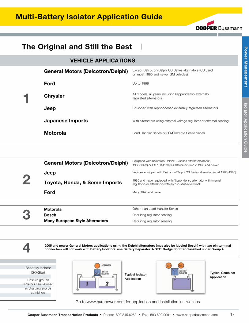
Multi-Battery Isolator Application Guide
VEHICLE APPLICATIONS
Except Delcotron/Delphi CS Series alternators (CS used
on most 1985 and newer GM vehicles)General Motors (Delcotron/Delphi)
Ford
Chrysler
Jeep
Japanese Imports
Motorola
Equipped with Delcotron/Delphi CS series alternators (most
1985-1993) or CS 130-D Series alternators (most 1993 and newer)
Other than Load Handler Series
Requiring regulator sensing
Requiring regulator sensing
Vehicles equipped with Delcotron/Delphi CS Series alternator (most 1985-1980)
1985 and newer equipped with Nippondenso alternator with internal
regulators or alternators with an “S” (sense) terminal
Many 1998 and newer
General Motors (Delcotron/Delphi)
Jeep
Toyota, Honda, & Some Imports
Ford
Motorola
Bosch
Many European Style Alternators
All models, all years including Nippondenso externally
regulated alternators
Up to 1998
Equipped with Nippondenso externally regulated alternators
With alternators using external voltage regulator or external sensing
Load Handler Series or 8EM Remote Sense Series
1
2
3
4
Schottky Isolator
ISO/Start
Positive ground
isolators can be used
as charging source
combiners
Typical Isolator Application
Typical Combiner Application
The Original and Still the Best
Cooper Bussmann Transportation Products
2005 and newer General Motors applications using the Delphi alternators (may also be labeled Bosch) with two pin terminal
connectors will not work with Battery Isolators: use Battery Separator. NOTE: Dodge Sprinter classified under Group 4
Po
we
r Ma
na
ge
me
nt
Isolato
r Ap
plicatio
n Guid
e
17

Special Design Features
Power Management
Cooper Bussmann Transportation Products
Po
we
r M
an
ag
em
en
tP
ow
er M
anag
emen
t
18

Intelligent Battery Saving Devices
˚ ˚
MODELDISCONNECT
VOLTAGECURRENT DESCRIPTION
Power Management
Cooper Bussmann Transportation Products
Po
we
r Ma
na
ge
me
nt
Po
wer M
anagem
ent
19

Special Design Features
Sure Power offers a wide variety of fully solid-state 24V and 12V flashers for heavy-duty, off-highway, truck
and commercial applications.
The family of Sure Power flashers has been designed, tested and manufactured to outperform all other
flashers on the market. Independent testing, along with extended use of these flashers in the harshest
environments, has proven the durability and reliability of Sure Power’s family of flashers to be unsurpassed.
This 100% solid-state, completely environmentally sealed family of flashers is designed to surpass the
toughest OEM and SAE specifications, and provide a fully featured and fully protected dependable operation.
Solid State Flashers
Cooper Bussmann Transportation Products
Po
we
r M
an
ag
em
en
tS
olid
Sta
te F
lash
ers
20

Tough and Dependable
MODEL OPERATING VOLTAGE CURRENT DESCRIPTION
Solid State Flashers
More Flash...for Less
The 1421 Flasher is a smaller, lighter, 100% solid-state two-wire turn signal flasher with less footprint than its
predecessor. The turn signal indicators connected to the unit will flash on and off at a rate and duty cycle controlled by
the unit. The rate and duty cycle are independent of the number and type of turn signal indicators. The flasher can
operate any number of both incandescent and LED based turn signal indicators as long as the load current does not
exceed 25A and the load is greater than the minimum load requirements. (Contact Sure Power regarding minimum load
requirements for LED compatibility.)
1421 12v 25A Solid-state 2-wire Hazard/Turn Signal Flasher Meets SAE J1690
MODEL OPERATING VOLTAGE CURRENT DESCRIPTION
Truck, Bus & Commercial
Used by many of the world’s leading truck and chassis manufacturers, this family of products has proven to provide one of
the industry’s most reliable and dependable flasher operations. Independent life cycle testing failed to find a failure before
the test was terminated at over 42 million flashes. Is it any wonder that both OEMs and fleets are using these to provide
dependable flasher operation and peace of mind?
1415
1417
1419
1419S
1425
1425MB
12V
12V
12V
12V
24V
24V
25A
38A
25A
25A
25A
25A
Solid-State 2-wire Hazard/Turn Signal Flasher
Solid-State 2-wire Hazard/Turn Signal Flasher
Solid-State 3-wire Remote Mount Hazard/Turn Signal Flasher
Solid-State 3-wire flasher with Audible Tone
Solid State 2-wire Hazard/Turn Signal Flasher
Solid-State 2-wire Hazard/Turn Signal Flasher w/ Mounting Bracket
MODEL OPERATING VOLTAGE CURRENT DESCRIPTION
Heavy-Duty Off-Highway
Sure Power Industries supplies the world’s leading manufacturers of heavy-duty equipment with the industry’s most
durable and reliable flashers. Capable of connecting to either 12V or 24V systems, these 100% solid-state units are
completely environmentally sealed and encapsulated as well as being shock and vibration resistant. Sure Power is
continually designing new models, including both North American and European versions.
1410
1412
12V or 24V
12V or 24V
12.6A
12.6A
Solid-State 2-wire Remote Mount Hazard/Turn Signal Flasher
Solid-State with Deutsch 3-Pin Connector
Cooper Bussmann Transportation Products
Po
we
r Ma
na
ge
me
nt
So
lid S
tate Flashers
21

Daytime Running Light Controls
Sure Power DRL Controls
Features
Quality
Automatically
turns on low-beam head lamps or DRL lamps at a reduced
voltage and significantly enhances vehicle safety
Simple
to install these readily adapt to existing electrical systems
Safe
protected against all failure modes, including loss of
ground, overcurrent and short-circuit conditions
Reliable
not affected by radio or electromagnetic interference
on model
possibilities
Cooper Bussmann Transportation Products
Po
we
r M
an
ag
em
en
tD
ayti
me
Run
ning
Lig
ht C
ont
rols
22

Reliable Operation, Increased Safety
Daytime Running Light Controls
Sure Power Daytime Running Light Controls adapt to existing systems, being designed to operate
Daytime Running Light Controls automatically activate when the ignition is turned on. However parking
brake release or other methods of activation are also possible.
FEATURESURE POWERLINEAR APPROACH
PULSE WIDTHMODULATION*
SERIESPARALLEL*
MODEL INPUT OUTPUT DIMENSIONS
Designed to eliminate radiated or conducted interference
YES
YES
YES
YES
NO. communications radios,
on-board computers, engine
& transmission controls.
NO.
NO. Major damage to module
can occur.
NO. Loss of ground may result in
loss of headlamps
NO.
over currentYES (electronic) YES. NO. Unless fuse added.
YES YES. NO. Unless fuse added.
Both lamps protected against
failsYES YES NO
YES YES NO
Low voltage protected YES NO NO
YES YES NO
which results in loss of both headlamps
YES YES NO
Cooper Bussmann Transportation Products
Po
we
r Ma
na
ge
me
nt
Daytim
e Running
Light C
ontro
ls
23

Power Distribution & Circuit Protection
Cooper Bussmann Transportation Products
Off-the-shelf and custom-designed
products that provide and protect
vehicle power distribution
Power Distribution ModulesElectronic Device Protection
CAN (J1939) Bus Interface Electrical Systems Protection
24

Cooper Bussmann Transportation Products
High Power Ratings
Multiplexing Capability
Flexible Configurations
Rugged Construction and Serviceable Design
Ignition Protected Options
Agency Compliant
easy
Custom Solutions for Power Distribution
Circuit Protection
Page
Page
25

31M Series Multiplexed Power Distribution Module
The multiplexed Vehicle Electrical Center (mVEC) offers economical CAN
Network oversight for high power circuits in vehicle power distribution.
Manufactured as a hardened and weather tight module, the mVEC is
rated at 200 Amps. The mVEC may be configured to provide various
OEM circuit protection and switching functions, using industry standard
fuses, relays and breakers, with the status and control of each circuit
accessible through J1939 CAN open messages. The mVEC is based on
proven and patented technology and is suited for the most demanding
transportation vehicle applications.
High Power: The mVEC uses patented Cooper Bussmann VEC 'power
grid' technology, ideal for high current circuits and Sure Power
networking electronics. Each mVEC is rated at 200 Amps, with individual
outputs rated up to 30A, and a maximum of 32 outputs possible with the
mVEC. 12 and 24 volt systems are supported.
Rugged: Waterproof to high pressure spraying (IP66). The mVEC is
designed and manufactured with robust features such as a heavy-duty
housing, silicon and Gortex gasketing, and protective conformal coated
electronics, to operate in demanding vehicle environments such as those
found in construction, agriculture, heavy truck, bus, RV, marine and
specialty vehicle markets.
Flexible: The mVEC is offered in various standard and customized
versions, with custom versions being configured to OEM wiring
requirements. The two standard mVEC configurations include the
8-relay 31M-000-2 and the 12-relay 31M-300-0. The mVEC accepts
relays, fuses, circuit breakers, resistors, diodes, etc. based on the
industry standard 2.8mm footprint.
Basic Features: The mVEC acts as a slave module on a J1939
network, communicating via the vehicle data bus with the master
controller. The mVEC functions as a node in an existing vehicle
J1939 multiplexing network. The mVEC controls relays via direction
of J1939 CAN bus and reports status of relays and fuses each
second to the J1939 CAN bus, indicating any blown fuse or failed
relay. The mVEC supports both 12V and/or 24V electrical
requirements. The mVEC is capable of custom designs with differing
configurations of relays, fuses, circuit breakers, etc. per customer
requirements.
Multiplexed Vehicle Electrical Center (mVEC)
Cooper Bussmann Transportation Products
Po
we
r D
istr
ibu
tio
nV
EC
Po
we
r D
istr
ibu
tio
nV
EC
mV
EC
26

31M Series Multiplexed Power Distribution Module
1. Mounting: compression limiters on mounting feet
2. Labeling to customer specifications
3. Stuffed (with/without components including, but not
limited to: fuses, relays, diodes, circuit breakers, fuse
puller)
4. Customized circuit layouts, standard and custom CAN messages
Output: Standard Cooper Bussmann VEC connectors
terminals (tanged/tangless)
Dimensions - mm(in)
Cooper Bussmann Transportation Products
Assembly shown with standardbrass grommet. 11.8±
m or 60 ft-lbs
Studded input shown,cover not shown
M6 or M8 input stud.(Stainless or plated steel)
120Shown w/ cover in closed position
Gasket Plug (optional)
Assembly shown withstainless steel compression limiter (optional)
or 300 ft-lbs
Yellow Silicone Gasket90 max
38.612.8
Specifications Specifications (Cont)
Options
Capacity: 200 Amps maximum rating, 30 Amps per output pin,
Maximum of 12 relays and/or 32 fuses, or various
combinations thereof (unique design configurations may
be required)
Materials: Housing and connector cavities: 94V0 rated thermoplastic
Internal power grid: tin-plated copper
CAN circuit board: conformally coated
Operating Temperature Ratings:
Ingress Protection: IP66 compliant
Foot Torque Rating: 60 in-lbs w/out compression limiters, 200 to
300 in-lbs with compression limiters.
Input:
grid (100A max per stud)
Bussmann 32004 VEC connectors (2 terminal,
colored/keyed, sealed connectors)
VEC Power Grid; uses Packard 800 series
terminals
CAN:
addressing, auxiliary relay control, and reserve connections
to mVEC 'smart' layer
Connections:
VE
CP
ow
er D
istrib
utio
nV
EC
mV
EC
27

32S Series Severe Service Power Distribution Module
Introducing the ruggedized version of the Cooper Bussmann Dual Vehicle
Electrical Center, the 'Severe Service' DVEC (ssDVEC). This version of the
DVEC features unequaled performance in power distribution in an IP66
compliant enclosure. The ssDVEC is capable of operating in various
environments such as those with high vibration and moisture, up to direct
high pressure spray. The ssDVEC provides efficient and compact power
distribution for OEMs with demanding applications in the transportation
industry including construction, agriculture, heavy trucks, bus, marine and
specialty vehicles.
As with all DVECs, the ssDVEC uses the patented Cooper Bussmann
'power grid' technology easily programmable to accommodate various
OEM wiring requirements.
Cooper Bussmann DVECs all feature a unique color-coded and
keyed connector system, and accepts common plug-in fuses,
relays, circuit breakers, resistors, diodes, etc., based on the industry
standard 2.8mm footprint.
Additionally the ssDVEC has these new features:
terminal interfaces
Severe Service Dual Vehicle Electrical Center (ssDVEC)
Cooper Bussmann Transportation Products
Po
we
r D
istr
ibu
tio
nV
EC
ssD
VE
C
28

32S Series Severe Service Power Distribution Module
Dimensions - (mm)
CONNECTOR 10
2 ROTCENNOC21 ROTCENNOC
CONNECTOR 3
CONNECTOR 4
CONNECTOR 5
CONNECTOR 7
CONNECTOR 11 CONNECTOR 1
CONNECTOR 9
CONNECTOR 6
CONNECTOR 8
230
212
162
120 147
8.4
4X compression limiter
9483
Optional bus bar
Cooper Bussmann Transportation Products
Optional laser etching
1. Labeling to customer specifications
2. Stuffed (with/without components including, but not
limited to: fuses, relays, diodes, circuit breakers, fuse
puller)
3. Customized circuit layouts, standard and custom CAN messages
4. Power Connector
Output: Standard Cooper Bussmann VEC connectors
terminals (tanged/tangless)
Specifications Specifications (Cont)
Options
Capacity: and/or 64 fuses, or various combinations thereof (unique design configurations may be required)
Materials: Housing and connector cavities: 94V0 rated thermoplastic
Internal power grid: tin-plated copper
Operating Temperature Ratings:
Ingress Protection: IP66 compliant
Foot Torque Rating: 200 to 300 in-lbs with standard compression limiters
Input:
power studs for DC power into the VEC power
Bussmann 32004 VEC connectors (2 terminal,
colored/keyed, sealed connectors)
terminals
Connections:
160.8(6.3)
Po
we
r Dis
tribu
tion
VE
CssD
VE
C
29

31S Series Severe Service Power Distribution Module
Introducing the ruggedized version of the Cooper Bussmann Vehicle
Electrical Center, the 'Severe Service' VEC (ssVEC). This version of the
VEC features unequaled performance in power distribution in an IP66
compliant enclosure. The ssVEC is capable of operating in various
environments such as those with high vibration and moisture, up to direct
high pressure spray. The ssVEC provides efficient and compact power
distribution for OEMs with demanding applications in the transportation
industry including construction, agriculture, heavy trucks, bus, marine and
specialty vehicles.
As with all VECs, the ssVEC uses the patented Cooper Bussmann 'power
grid' technology that is easily programmed to accommodate various OEM
wiring requirements.
Cooper Bussmann VECs all feature a unique color coded and keyed
connector system, and accepts common plug-in fuses, relays, circuit
breakers, resistors, diodes, etc., based on the industry standard 2.8mm
footprint.
Additionally the ssVEC has these new features:
including a Gortex vent
terminal interfaces
The ssVEC features various custom design versions (differing relay,
fuse, breaker, etc. configurations) supporting 12V and 24V electrical
systems (or combinations thereof).
Severe Service Vehicle Electrical Center (ssVEC)
Cooper Bussmann Transportation Products
Po
we
r D
istr
ibu
tio
nV
EC
ssV
EC
30

31S Series Severe Service Power Distribution Module
Dimensions - mm
Cooper Bussmann Transportation Products
Removal Tool.
166.2
Yellow silicone gasket (seal)
(Post-stakeheight)
1. Compression limiters on mounting feet
2. Labeling to customer specifications
3. Stuffed (with/without components including, but not
limited to: fuses, relays, diodes, circuit breakers, fuse
puller)
4. Customized circuit layouts
5. Power connector
Output: Standard Cooper Bussmann VEC connectors
terminals (tanged/tangless)
Specifications Specifications (Cont)
Options
Capacity:
combinations thereof (diverse design configurations
supported)
Materials:
Internal power grid: tin-plated copper
Internal gaskets stud input covers: silicone
Operating Temperature Ratings:
Ingress Protection: Application dependant up to IP66 equivalent
(direct high pressure spray)
Maximum Torque Rating: compression limiters, 24 in-lbs without compression limiter.
Input:
colored/keyed, sealed connectors)
terminals
Connections:
Po
we
r Dis
tribu
tion
VE
CssV
EC
Laser etching on the
inside or outside cover (optional). Shown w/ cover closed.
Blank connector shown.
31

Series 32000 Vehicle Electrical Centers
Cooper Bussmann Transportation Products
Series 32000 Vehicle Electrical Centers
Po
we
r D
istr
ibu
tio
nV
EC
DV
EC
32

Series 32000 Vehicle Electrical Centers
Cooper Bussmann Transportation Products
Dimensions - mm(in)
Specifications Options
Input Terminal Rating:
Output Terminal Rating:
Materials:
Operating Temperature Ratings:
Ingress Protection:
Mounting Torque Rating:
Termination: ®
®
Cover:
Cover Label:Input Style: Mounting:
Components:
Severe Service:
Fuse/breaker Extraction Tool:
Each design is customer specific. Consult your sales rep today
for your application.
I/O #4 I/O #3
Po
we
r Dis
tribu
tion
VE
CD
VE
C
33

Series 31000 Vehicle Electrical Centers
Cooper Bussmann Transportation Products
Series 31000 Vehicle Electrical Centers
Po
we
r D
istr
ibu
tio
nV
EC
31
XX
X V
EC
34

Series 31000 Vehicle Electrical Centers
4X #10 INTERNALMOUNTING HOLESMOUNTING TORQUERECOMMENDATIONS
6.56[.26] OPTIONALEXTERNAL MOUNTING FEET(CONSULT FACTORY)
BUILT IN DRAINAGE
106.6 [4.20]
73.00 [2.87]
73.00 [2.87]
106.6 [4.20]
I/O #5I/O #6
I/O #4
I/O #3
I/O #2CONNECTOR #1INPUT/OUTPUT
SPLASHPROOFASSEMBLY
OPTIONAL COVER(SPLASHPROOF &
VENTED VERSIONS)
CONNECTOR LOCK
69.64 [2.74]
1.90 [.07]
22.49 [.89]
15.23 [.60]
146.59 [5.77]
108.86 [4.29]
Cooper Bussmann Transportation Products
Dimensions - mm(in)
Specifications Options
Input Terminal Rating:
Output Terminal Rating:
Materials:
Operating Temperature Ratings:
Ingress Protection:
Mounting Torque Rating:
Termination: ®
®
Cover:
Cover Label:Input Style: Mounting:
Components:
Severe Service:
Fuse/breaker Extraction Tool:
Each design is customer specific. Consult your sales rep today
for your application.
Po
we
r Dis
tribu
tion
VE
C3
1X
XX
VE
C
Standard VEC shownwith vented cover
119
40
119 2
67
40
35

Vehicle Electrical Center Connectors
32006-XXX Output Connector
32004-XX Power Connector
Terminal position assurance32004-TPX
Seal
Male Input Connector 32004-xx
Female Terminal*Delphi Packard 800Metri-Pack® series
shown Cable sealDelphi Packard #12129381r
shown
32004-CP Shown Assembled In-Place
32004-CP Shown Prior To Engagement
VEC Female Input Connector(Shown For Reference Only)
Male Input Connector Assembly
MALE INPUT CONNECTOR32004 - X X
Sealed / Non-Sealed Configuration1 = Non-Sealed Version2 = Sealed Version
Color of PartA = BlackB = Gray
TERMINAL POSITION ASSURANCE32004 -TPX
CONNECTOR POSITION ASSURANCE32004 - CP (Ship in Bulk)
Sealed / Non-Sealed Configuration1 = Non-Sealed Version2 = Sealed Version
Note: Terminals and Terminal Seal
Components are not provided with connectors.
Available from Delphi Packard. Contact factory
for part list and terminal removal tool. Sealed
connector option includes outer body seal.
(Dims.shown are for reference only. Consult factory for latest prints)
(Dims.shown are for reference only. Consult factory for latest prints)
Terminal position assurance32006-TPX
Seal
Male Output Connector 32006-xxx
Female Terminal*Delphi Packard 280Metri-Pack® series
shown
Cable SealDelphi Packard 280Metri-Pack® series
shown
H G F
B C D
24.4(0.96)
26.3(1.04)
17.9(0.71)
39.9(1.57)
30.8(1.21)
Male Output Connector Assembly
VEC Female Output Connector(Shown For Reference Only)
32006-CP Shown Assembled In-Place
32006-CP Shown Prior To Engagement TERMINAL POSITION ASSURANCE
32006 - TPX Sealed / Non-Sealed Configuration1 = Non-Sealed Version2 = Sealed Version
CONNECTOR POSITION ASSURANCE32006 - CP (Ship in Bulk)
Note: Terminals and Terminal Seal
Components are not provided with connectors, but
are available from Delphi Packard. Contact factory
for part list and terminal removal tool. Sealed
connector option includes outer body seal.
Sealed / Non-Sealed Configuration1 = Non-Sealed Version2 = Sealed Version
Connector Cavity Configuration1 = Tang-less Female Connector (Delphi 280)2 = with Tang Female Connector (Delphi 280)P = all cavities plugged
Color of PartA = Black E = YellowB = Gray F = RedC = Green G = OrangeD = Blue H = BrownJ = Neutral (only available for -JP2 option)
MALE OUTPUT CONNECTOR32006 - X X X
(Dims. shown are for reference only. Consult factory for latest prints)
(Dims. shown are for reference only. Consult factory for latest prints)
26.8(1.06)
30.3(1.19)
46.2(1.82)
Dimensions - mm(in)
Cooper Bussmann Transportation Products
Po
we
r D
istr
ibu
tio
nV
EC
VE
C C
on
ne
cto
rs
36

VEC Electrical Components
OPTIONAL"WING"
FOR ADDITIONALDIODE KEYING
STANDARDDIODE KEY
DIODE MARKINGSHOWN
][0.0902.29
][0.9123.0
][0.369.2
][0.307.6
][0.358.9
][1.0727.3
][0.256.4
][0.4812.2
][0.153.8][0.030.8][ 0.112.8
][8.13.32
22901 SeriesTransorb
22902 SeriesResistor
22903 SeriesDiode
VEC Accessories
Series 229 Diode, Resistor, and Transorb
Specifications Dimensions - mm(in)
(Dims. shown are for reference only. Consult factory for latest prints)
Ratings: Consult factory for available ratings and part numbersMaterials: Grey 94V0 thermoplastic housing with metal cover.Termination Type: Compatible with 280 Type fuse blocks using 8.1mmcenterline.Diode Key Feature: Standard key denotes installation direction.Extended key available for error-proof installation in VEC.
Types: 5-pin mini-relay, 12Vdc & 24Vdc5-pin micro-relay, 12Vdc & 24Vdc4-pin mini-micro relay, 12Vdc
Consult Factory for available amperage ratingsTermination Type: Compatible with 280 Type fuse blocks using 8.1mm centerline.Sealed versions of some relays also available.
Specifications
Relays (Only Available for VEC, DVEC, RFRM, or RTMR Applications.)
DVEC Cover TetherTether available for use withSeries 32000 DVEC cover.Consult factory.
Cooper Bussmann Transportation Products
Series B109-7031(for use with Series 32000 DVEC)External bus bar can be used with the Dual VEC tobus together studded power inputs.
Po
we
r Dis
tribu
tion
VE
CV
EC
Ele
ctric
al C
om
po
ne
nts
Series 32011BS (Input Connector Cap) &Series 32012BS (Output Connector Cap)Connector caps can be assembled to the mating VEC harness connectors (Series 32004 & 32006) when not in use.
37

Series 15400 RFRM Rear-fed Fuse & Relay Module
Dimension - mm
Specifications
Cooper Bussmann Transportation Products now offers a main power
distribution module capable of operating in harsh environment applications.
Based on the industry standard 2.8mm (mini) footprint, the RFRM can accept
plug-in fuses, relays, circuit breakers, resistors and diodes to meet numerous
power management requirements. The RFRM is available with multiple internal
bussing options, accommodating various OEM wiring requirements.
Material: UL-Rated 94V0 thermoplastic, plated copper bus bar, silicone
rubber gasket, EPDM – internal tether
Power Ratings: Nominal 12Vdc and 24Vdc systems, 100A per bus bar,
200A Max
Temperature Rating: -40˚ C to 85˚ C
Ingress Protection: IP66 (with use of cover and seal) 1
Plug-in Capacity: Up to 10 micro relays and a combination of 40
fuses/circuit breakers (8.1mm CL)
Mounting: #10-32 or M5 x 0.8 available, 24 in-lbs max
Orientation mounting application intended for horizontal to vertical 2
Electrical Connectors: Output cavities (holes in back)
Wire Size: Accepts #12-22 AWG wire sizes 3
Terminals: Delphi Packard 280 Series Metri-Pack® sealed/tang style
terminals
Cavity Plugs: Delphi Packard 280 Series cavity plug (where output
wires are not used) Input Studs (for bussed version): M8 x 1.25
thread, 70 in-lbs max
Part Numbering System Notes
Notes: 1. Ingress Protection rating has been validated with approved panel mounting applications. Consult factory for testing procedures.2. Consult factory for any other mounting orientation. 3. Cooper Bussmann does not supply wires, wire terminals, terminal seals, or cavity plugs.- Consult factory for options including custom labels and replacement accessories.
Mounting cut out dimensions above –RFRM designed to be mounted from rear of panel
124.4 REF
197.5 REF
Mounting cut out dimensions above –RFRM designed to be mounted from rear of panel
Cable Managers-Options shown on thisdrawing only
1. Internal tether accessory not shown – it is included with Cover Option 1.
2. Photograph above shows RFRM with optional yellow fuse puller tool. Yellow Fuse
Puller (part #32013BS) tool sold separately.
3. Photograph above shows RFMR ‘stuffed’ with components such as fuses and
relays. RFRMs are sold without components.
4. Under side of RFRM has the wire harness position labeling details molded into
the part.
235.0 REF216.0 REF
70.0 REF4X THREADED MOUNTINGINSERTS#10-32 ORM5X0.8
216.00
4X ø5.670.00 R1.0 TYP
4X R10.0
215.00199.00
96.0011.00TYP
M8X 1.25 Threadon input studs
Optional Hardware
94.3 REF
2X Input StudsM8 x 1.25
154X X X X X X XA - Standard Bussmann LabelB-Z - Private Label
Label0 - Standard Label1 - 1st Non-Standard Label2 - 2nd Non-Standard LabelCover
0 - No Cover1 - Standard Cover with Bussmann Logo (Consult Factory for Special Options)Hardware
0 - W/O Nuts1 - Nuts Shipped Bulk2 - Nuts Shipped Assembled
Base1 - Base with English MTG Inserts and Cable Managers2 - Base with English MTG Inserts w/o Cable Managers3 - Base with Metric MTG Inserts and Cable Managers4 - Base with Metric MTG Inserts w/o Cable Managers
Bus Bars1 - Dual Bus Bars2 - Bus Bar Left Hand Side Only3 - Bus Bar Right Hand Side Only 4 - No Bus Bars
0 - Standard RFRM
Cooper Bussmann Transportation Products
Po
we
r D
istr
ibu
tio
nP
DM
15
40
0 R
FR
M
38

Series 15310 60-Position RTMR
RTMR Product Features
Dimensions - mm(in)
Blade Terminals: Accepts ATM (mini) blade fuses, circuit breakers as well as other
components such as relays, diodes, flashers, etc. with 2.8mm blades on 8.1mm centerline
spacing
Mounting: #10-32 or M5 Threaded inserts; 24 in-lbs (2.7N m) max torque
Material: Housing and cover: black thermoplastic
Labels: Component location IDs molded on top of housing; custom inside cover labels
available. Contact factory for information.
Ratings: 30A max per terminal; 12/24Vdc
Temperature Rating: -40°C (-40°F) to 125°C (260°F) (rating on PDM only)
Ingress Protection Rating: IP66–IEC 529 (valid when properly installed with cover, cable
seals and cavity plugs. Contact factory for specific IP test specifications applicable to
RTMR).
Electrical Connections: Output cavities (holes in back of unit):
Wire Size: #12-#20 AWG
Terminals: Tyco AMP® MCP2.8 Series
20-16 AWG (0.50-1.00mm2): Terminal #1-968855-1 Seal #828904-1
14-12 AWG (1.50-2.50mm2): Terminal #1-968857-1 Seal #828905-1
Cavity Plugs: Tyco AMP® MCP2.8 Series #828922-1 (where output wires are not
used)
Notes:
1. Cooper Bussmann does NOT supply wires, wire terminals, terminal seals or cavity
plugs.
2. Mounting brackets offered for surface mounts.
3. Consult factory for options including custom labels and replacement accessories.
4. 15310 series uses Tyco terminals vs. Delphi as commonly used with our standard
RTMR series
Non-Bussed Rear Terminal Mini Fuse & RelayCooper Bussmann Transportation Products offers a power distribution module called
the 60-Position Rear Terminal Mini-Fuse and Relay panel (15310 Series.) The 15310
offers the same benefits as the standard Cooper Bussmann RTMR, however, it has a
higher component density. There are 60 open cavity positions versus the 50 maximum
positions of the standard RTMR. This allows you to install more fuses, breakers,
diodes or relays without increasing any outer dimensions! The unit is non-bussed to
allow you to place components anywhere within the block. This makes the 15310
suitable for virtually any application in marine, construction, agriculture, heavy trucking,
and specialty vehicle industries. With cover, cable seals and cavity plugs installed, the
15310 is a weather tight enclosure (IP66) for power distribution. (The 15310 uses the
same covers and mounting as the standard RTMR.)
Part Numbering System
Marking Options
Consult factoryfor custom
marking options
Cover Options
0 - No Cover1 - Fuse Cover2 - Relay/CB Cover
1 - #10-32 threaded insert2 - M5 threaded insert
-
MountingOptionSeries
-15310
Cooper Bussmann Transportation Products
75.40 +0.25-0.13
2.969 +.009-.005
2x ø6.35±0.05[.250±.001]w/ 0.38 [.015] x 45° CHAMFERBOTTOM SIDE, CLEARANCE HOLEFOR THREADED INSERTS
105.83[4.167]
102.83[4.048]
99.58 ±0.15[3.920 ±.005]
1.50[.060] HIGH CHARACTERS MOLDED0.13/0.26[.005/.010] BELOW SURFACE
1.50[.060] HIGH CHARACTERS MOLDED0.13/0.26[.005/.010] BELOW SURFACE
62.83[2.474]
56.83[2.237]
53.58 ±0.25[2.109 ±.009]
90.78[3.574]
1.50[.059]25.00
[.984]
8.00[.315]
96.68[3.806]
50.68[1.995]
30.35[1.195]
1.50[.050] HIGH CHARACTERS MOLDED0.13/0.26[.005/.010] BELOW SURFACE
84.70±0.30[3.335±.012]
16.00[.630]
16.00[.630]
1.50[.059]
1.50[.059]
8.00[.315]
103.24[4.065]
113.24[4.458]
8.00[.315]TYP
CHANGEABLE INSERT FOR PART NO.3.30[.118] HIGH CHARACTERS MOLDED
0.13/0.26[.005/.010] ABOVE SURFACE
1.90[.075]
TYP
CHANGEABLEINSERT FOR
YEAR/MONTHDATE CODE
CHANGEABLEINSERT FOR REVISION
NUMBER
Po
we
r Dis
tribu
tion
PD
MS
erie
s 15
31
0 6
0-P
ositio
n
39

Series 15300 RTMR
Torque Rating: 50 in-lbs (5.5N m) max.
Mounting Torque Rating: #10-32 or M5 threaded inserts; 24
m) max torque.
Ingress Protection Rating:
Options
End Caps:versions.
Mounting:RTMR. (See page 41.)
Labels:
Replacement Accessories:
parts.
application need.
Specifications
Input Terminal Rating:
Output Terminal Rating: 2.8mm blade terminals (30A max per terminal)
Temperature Rating: 2.8mm blade terminals (30A max per terminal)
Materials: Black thermoplastic housing; Tin-plated copper internal bussing;
Bright nickel-plated brass studs (on bussed versions).
Termination:(sealed/tangless
*Electrical terminals, cable seals & cavity plugs are NOT supplied by Cooper Bussmann
Rear Terminal Mini Fuse & Relay
Cooper Bussmann Transportation Products
Po
we
r D
istr
ibu
tio
nP
DM
15
30
0 R
TM
R
40

Series 15300 RTMR
Dimensions - mm(in) (Dims. shown are for reference only. Consult factory for latest prints)
Part Numbering System
Mounting Brackets
–
–RTMR Stud End Cap
– Material
–
O – Plated steelP– Stainless steel
0 - No Cover
3 - Fuse Cover
4 - Relay/c.b. Cover
0 - No Nuts
1 - Nuts (Shipped Bulk)
2 - Nuts (Shipped Assembled)
2 - Nuts (Shipped Assembled)
3 - Stud Caps (Shipped Bulk)
4 - Stud Caps (Shipped Assembled)
5 - Nuts And Stud Caps (Shipped Bulk)
6 - Nuts And Stud Caps (Shipped Assembled)
1 - Fuse/C.B. Base (For 20 Fuses/C.B.)
2 - Micro Relay Base (For 5 Micro Relays W/ 10 Fuses/C.B.)
3 - Mini Relay Base (For 3 Mini Relays W/10 Fuses/C.B.)
4 - Wired Base (Non Bussed) (No Input Studs) (For Fuses/C.B. And Relays)
5 - Wired Base (Input Stud Fuse Side Only) (For Fuses/C.B. And Relays)
6 - Wired Base (Input Stud Relay Side Only) (For Fuses/C.B. And Relays)
3 - #10-32 Insert (English
4 - M5x0.8 Insert (Metric)
Special Labels
Consult Factory
Cooper Bussmann Transportation Products
59.3(2.33)
62.8(2.47)
105.4(4.15)
73.3(2.89)
25.0(.98)
75.0(2.95)
86.0(3.39)
90.6(3.57)
112.8(4.44)
THREADED INSERT15303-3 #10-32 INSERT15304-4 M5 X 0.8 INSERT
GORE AUTOMOTIVEVENT USED WITHFUSE COVER ONLY
34.6(1.36)
106.3(4.19)
FUSECOVERSHOWN
60.3(2.37)
RELAY/C.B.COVERSHOWN
ISOMETRIC VIEWSCALE: 1:1
TANGLESS FEMALE TERMINALDELPHI PACKARD280 METRI-PACK SERIES12 GA. TO 20 GA.(SEE NOTE 1)
CABLE SEALDELPHI PACKARD280 METRI-PACK SERIES(SEE NOTE 1)
SEAL CONNECTOR PLUGDELPHI PACKARKPART NO. 12010300(SEE NOTE 1)
STUD CAPS(OPTIONAL)
HEX NUTS(OPTIONAL)
FUSE BASE
MICRO/MINI BASE
Base OptionsMountingHardwareOptions
CoverOptions
MarkingOptionsSeries
Po
we
r Dis
tribu
tion
PD
M1
53
00
RT
MR
1 5 3 0
B 0 2 8 7 0 1 2 B 0 6 6 7 0 0 8
41

Series LMG Bolt-in Fuse Holder for Multiple AMG Fuses
Cooper Bussmann Transportation Products now offers a heavy power
distribution module called the LMG (a.k.a “Big Block”). The LMG is
used for main branch primary fusing and accepts multiple (2, 3, or 5)
industry standard AMG fuses. Using a common input bus bar, the
LMG requires just one input connection to power all fuses.
Power Distribution Module
Marine ConstructionAgriculture Heavy Trucking Bus Specialty Vehicles
The Big Block provides efficient power distribution suitable for many
“under the hood” applications such as:
Sizing:
Ratings:
Temperature:
Termination:
Torques:
Material:
2, 3 and 5 positions available
Maximum total combined rating is 300A continous*.
-40˚C (-40˚F) to 85˚C (185˚F)
-18 or M8 studs, nuts, and lockwashers for fuse and surface mountings
Mounting: 100 in-lbs (11.3N m) max; Power input/output: 120 in-lbs (13.6N m) max
Housing: Black UL-Rated 94V0 thermoplastic
Cover: Red EPDM cover for protection from accidental shorts
Studs: Plated steel
*Based on numerous variations possible between # of LMG poles, fuses selected, input
wiring, and output wiring, all applications should be tested by the installer to verify the
product meets their requirements. Housing must not exceed 130 degrees C.
516
Cooper Bussmann Transportation Products
Po
we
r D
istr
ibu
tio
nF
us
e P
an
els
LM
G
42
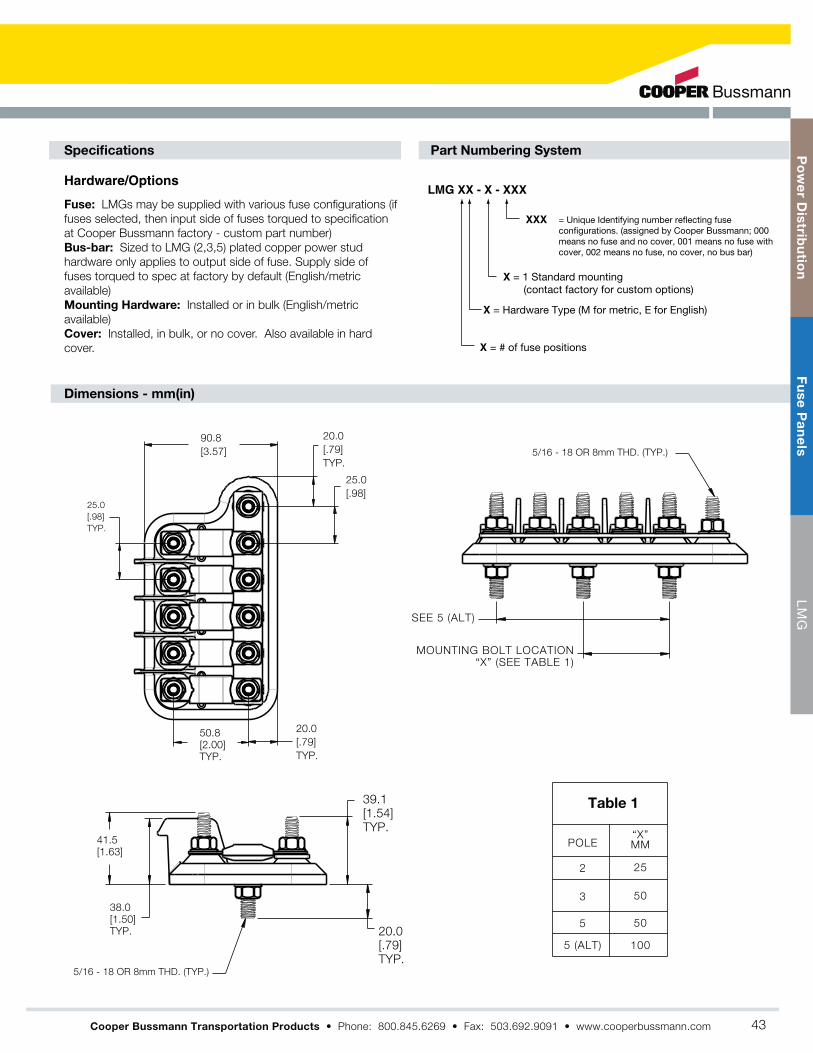
Hardware/OptionsLMG XX - X - XXX
XXX
X = 1 Standard mounting (contact factory for custom options)
X = # of fuse positions
X = Hardware Type (M for metric, E for English)
Fuse: LMGs may be supplied with various fuse configurations (if
fuses selected, then input side of fuses torqued to specification
at Cooper Bussmann factory - custom part number)
Bus-bar: Sized to LMG (2,3,5) plated copper power stud
hardware only applies to output side of fuse. Supply side of
fuses torqued to spec at factory by default (English/metric
available)
Mounting Hardware: Installed or in bulk (English/metric
available)
Cover: Installed, in bulk, or no cover. Also available in hard
cover.
= Unique Identifying number reflecting fuse configurations. (assigned by Cooper Bussmann; 000 means no fuse and no cover, 001 means no fuse with cover, 002 means no fuse, no cover, no bus bar)
Table 1
25.0
[.98]
TYP.
90.8
[3.57]
20.0
[.79]
TYP.
25.0
[.98]
20.0
[.79]
TYP.
50.8
[2.00]
TYP.
41.5
[1.63]
38.0
[1.50]
TYP. 20.0
[.79]
TYP.
39.1
[1.54]
TYP.
5/16 - 18 OR 8mm THD. (TYP.)
5/16 - 18 OR 8mm THD. (TYP.)
SEE 5 (ALT)
MOUNTING BOLT LOCATION“X” (SEE TABLE 1)
POLE
2
3
5
5 (ALT)
“X”MM
25
50
50
100
Specifications
Dimensions - mm(in)
Part Numbering System
Cooper Bussmann Transportation Products
Po
we
r Dis
tribu
tion
Fu
se
Pa
ne
lsL
MG
43

LMI Bolt-in Fuse Holder for Single or Multiple AMI Fuses
Cooper Bussmann Transportation Products now offers a heavy
duty fuse panel called the LMI “Little Block”. The LMI is used for
main branch primary fusing and accepts multiple (up to six)
industry standard AMI fuses. Sold by component or assembled,
the LMI uses a common input bus bar for assemblies of two or
more fuses.
The LMI provides efficient power distribution suitable for many
“under the hood” applications such as:
Marine
Sizing: One Fuse Module per AMI fuse
One input module and bus bar required per LMI2 – LMI7 assembly
Maximum of seven modules per assembly
Ratings: Maximum total combined rating is 400 amps continuous*
-40˚C (-40˚F) to 85˚C (185˚F)
Input Module: Stainless Steel M8 or -18 stud and keps nut
Fuse Module: Stainless Steel M5 or #10-24 studs and keps nuts
Mounting: 22 in-lbs (2.5 N m)
Fuse Module: 39.8 in-lbs (4.5N M)
Input Module: 75 in-lbs (8.5N M)
Material: Housing: HTN black UL-rated 94V0 thermoplastic material
Cover: Red EPDM/Santoprene cover for protection from accidental
shorts
Studs: Stainless Steel
Power Distribution Module
516
* Based on numerous variations possible between numbers of poles used, fuses selected, input
wiring, and output wiring, all applications should be tested by installer to verify the product meets
their requirements.
Po
we
r D
istr
ibu
tio
nF
us
e P
an
els
LM
I
44

25.1.99
182 REF
692.72
7.17
REF3.11
79
22.87
1.08
REF27.5
31.1 REF
1.22
H -- Fuse Module w/100a AMI FuseG -- Fuse Module w/80a AMI Fuse
1 -7 [Number of total modules (fuse modules and/or
M -- Metric
1 -- SS Keps Nut In Bulk (For individual components only)
J -- Fuse Module w/150a AMI FuseI -- Fuse Module w/125a AMI Fuse
input modules); 7 Max]
B -- Fuse Module w/40a AMI Fuse
Stud Option:E -- English
2 -- SS Keps Nut Installed (Only for assembled LMI2-LMI7)
C -- Fuse Module w/50a AMI Fuse
F -- Fuse Module w/70a AMI Fuse D -- Fuse Module w/60a AMI Fuse
LMI X -X -X -X(XXXXXX)
K -- Fuse Module w/175a AMI Fuse
HARDWARE OP ION:0 -- No Hardware (For individual components only)
L -- Fuse Module w/200a AMI Fuse
Up to 7 digit sequence representing each module in assembly, from left to right, with Busbar in thefront/bottom, uses below code:
0 -- Fuse Module w/o Fuse (i.e. empty fuse module)1 -- Input ModuleA -- Fuse Module w/30a AMI Fuse
2
LMI FUSE MODULE
LMI INPUT MODULE
AMI FUSE4
BUSBAR
1
3
I EM DES RIP ION
LMI7
1. All modules (input or fuse holder) will match same units in a given assembly, either all metric or all English as specified.
2. "E" Represents "10-32" stud for fuse module and "5/16-18" for input module. "M" represents M5 stud for fuse module and M8x1.25 size for input
module.
3. The largest an LMI should be is 7 modules total; 6 fuse modules and one input module. At most, 7 positions can be shown in suffix -X(XXXXXX).
4. Cooper Bussmann does not recommend more than 6 fuse modules being connected together (with one input module). The input module should
be located in the center of the assembly.
5. Bus bars are included for all assemblies greater than or equal to an LMI2.
6. Based on numerous variations possible between numbers of poles used, fuses selected, input wiring, and output wiring, all applications should be
tested by installer to verify the product meets their requirements.
7. All modules come with covers.
8. When ordering individual LMI modules for assembly by the customer, bus bars can be individually ordered using part # B109-7046-2/3/4/5/6/7,
with the last digit representing the number of total modules that the bus bar will connect.
9. When ordering LMI1 with fuse and/or nuts, both fuse and nuts will ship in bulk.
10. To order assembled units, the minimum order quantity is 100 units.
11. Attach all wire cables with the ring terminals in direct contact with the fuse or bus bar.
Notes
3
4
2
1
Po
we
r Dis
tribu
tion
Fu
se
Pa
ne
lsL
MI
45

Series 15710 Rear Terminal ATC Fuse Panel
Specifications
Options
Dimensions - mm(in)
Part Numbering System
The Rear Terminal ATC® Fuse Panel (RTA) is a rear-fed panel with high component
retention, which makes it an ideal choice for high vibration environments including
construction, agriculture, bus, RV, heavy trucking equipment, etc. It is available in multiple
lengths and internal bussing configurations. This allows for up to three separate power input
circuits and 32 individual output circuits.
Input Terminal Rating: 1/4-20 stud; Quick-connect terminals provided on middle bus
(Series 15713). 200A max total input for unit.
Output Terminal Rating: 30A max load per circuit.
Temperature Rating: –40°F (–40°C) to 260°F (125°C)
Materials: Black thermoplastic.
Termination: Delphi Packard Pack-Con® Series 3 & 5.* Input Wire Size: #4-6 AWG
Output Wire Size: #10-16 AWG
Torque Rating: 50 in-lbs (5.6N m) max.
Mounting Torque Rating: #10-32 threaded inserts, 24 in-lbs (2.7N m) max torque.
Positions: 8-32 Circuits available.
Split Power: Single, dual, or triple bus options
Cover: Splash-resistant covers available. Short cover for fuses only, and taller
cover for use with circuit breakers
Locks: Secondary locks available for securing of output terminals (#15710-TP).
(Comes in multiples of 8 positions. Must order multiple strips to cover length of
selected RTA.)
Tools: Output terminal removal tool (#HT15710-01). Secondary lock removal
tool (#HT15710-02).
*Electrical Terminals are NOT supplied by Cooper Bussmann.
®
QUICK-CONNECT TERMINALS(Series 15713) 1/4-20 STUD (2 PLACES)
10-32 THREADED INSERTS (4 PLACES)
166.5147.032 POLE
146.5127.028 POLE
126.5107.024 POLE
107.087.520 POLE
87.067.816 POLE
67.048.012 POLE
47.528.08 POLEVALUEDIM 'B'
VALUEDIM 'A'
][1.3133.3
A
B
][ 1.3835.0
][ 0.4812.1
][ 0.4110.5
][ 2.3459.4
[2.94± .20]74.7± 0.5
[3.38±.20]85.8±0.50
][ 0.4210.7
][ 0.7418.8 Middle bus has quick-connect terminals
(series 15713 only)
COVERTETHER
49.55 [1.95] FUSE
COVER
66.28 [2.61]
BREAKERCOVER
Series
1 5 7 1
1 – Single Stud, Single Supply Circuit2 – Double Stud, Split Supply Circuit3 – Triple Buss, Split Supply Circuit
Hardware
Options
0 – W/O nuts1 – Nuts shipped bulk2 – Nuts assembled
Cover
Option
0 – No cover1 – w/ fuse cover2 – w/ CB cover
Marking
Option
A-Standard(consult factory forspecial marking
No. of
Positions
– –108-32
– – –2Left Side Right Side06-28 04-28
(max. tot 32) (increments of 4)
– - –3Total Pos Left Side14-32 06-24(max. total of 32) (increments of 4)
Cooper Bussmann Transportation Products
Po
we
r D
istr
ibu
tio
nF
us
e P
an
els
Se
rie
s 1
57
10
46
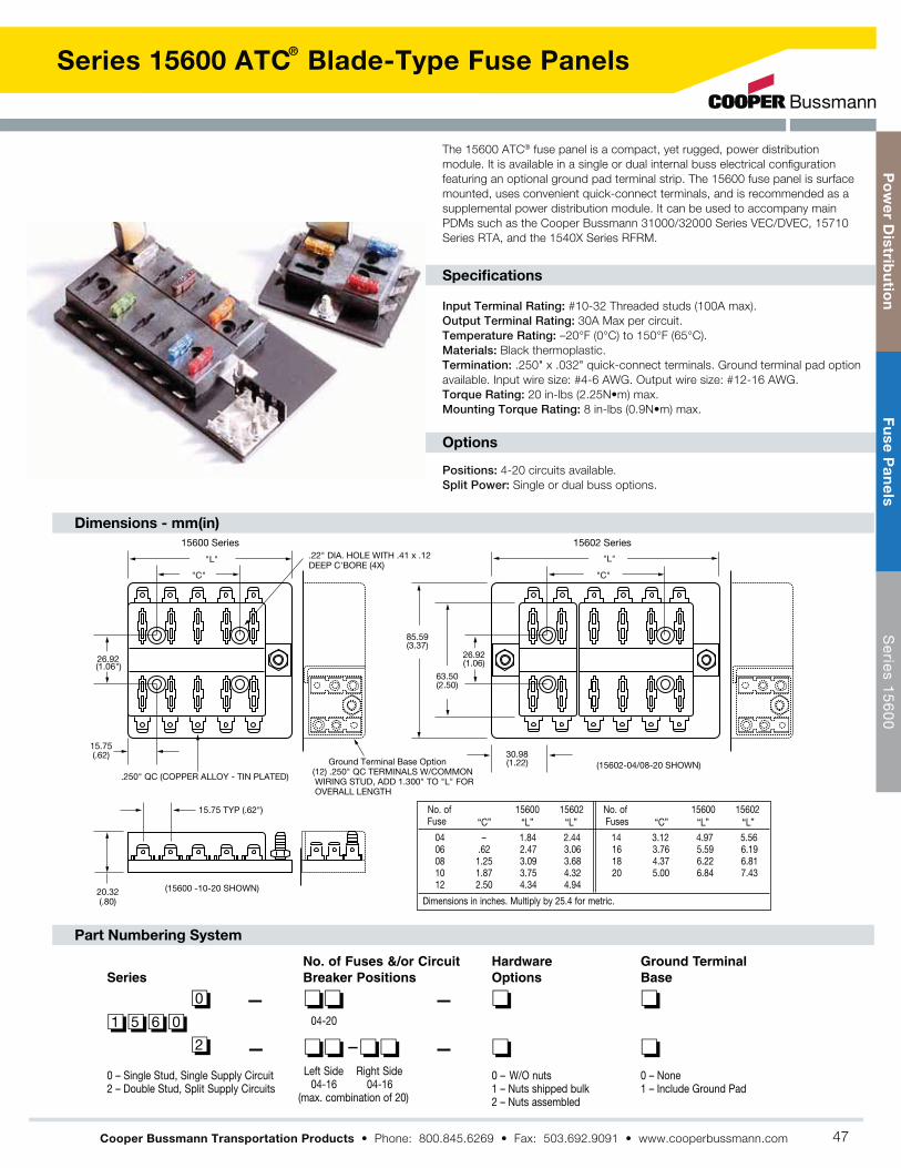
Series 15600 ATC Blade-Type Fuse Panels
Dimensions - mm(in)
Part Numbering System
Positions: 4-20 circuits available.
Split Power: Single or dual buss options.
®
Specifications
Options
The 15600 ATC® fuse panel is a compact, yet rugged, power distribution
module. It is available in a single or dual internal buss electrical configuration
featuring an optional ground pad terminal strip. The 15600 fuse panel is surface
mounted, uses convenient quick-connect terminals, and is recommended as a
supplemental power distribution module. It can be used to accompany main
PDMs such as the Cooper Bussmann 31000/32000 Series VEC/DVEC, 15710
Series RTA, and the 1540X Series RFRM.
Input Terminal Rating: #10-32 Threaded studs (100A max).
Output Terminal Rating: 30A Max per circuit.
Temperature Rating: –20°F (0°C) to 150°F (65°C).
Materials: Black thermoplastic.
Termination: .250" x .032" quick-connect terminals. Ground terminal pad option
available. Input wire size: #4-6 AWG. Output wire size: #12-16 AWG.
Torque Rating: 20 in-lbs (2.25N m) max.
Mounting Torque Rating: 8 in-lbs (0.9N m) max.
"L"
"C"
(1.06")26.92
(.62)15.75
15.75 TYP (.62")
(.80)20.32
.250" QC (COPPER ALLOY - TIN PLATED)
(15600 -10-20 SHOWN)
.22" DIA. HOLE WITH .41 x .12DEEP C'BORE (4X)
(12) .250" QC TERMINALS W/COMMON WIRING STUD, ADD 1.300" TO "L" FOR OVERALL LENGTH
"L"
"C"
(3.37)85.59
(2.50)63.50
(1.06)26.92
(1.22)30.98
(15602-04/08-20 SHOWN)
15600 Series 15602 Series
Ground Terminal Base Option
No. of 15600 15602 No. of 15600 15602Fuse
04 – 1.84 2.44 14 3.12 4.97 5.5606 .62 2.47 3.06 16 3.76 5.59 6.1908 1.25 3.09 3.68 18 4.37 6.22 6.8110 1.87 3.75 4.32 20 5.00 6.84 7.4312 2.50 4.34 4.94
Dimensions in inches. Multiply by 25.4 for metric.
“L”“L”“L” “C”“C” “L”Fuses
No. of Fuses &/or CircuitBreaker Positions
– –004-20
– – –2
Left Side Right Side04-16 04-16
(max. combination of 20)
Series
1 5 6 0
0 – Single Stud, Single Supply Circuit 2 – Double Stud, Split Supply Circuits
HardwareOptions
0 – W/O nuts1 – Nuts shipped bulk2 – Nuts assembled
Ground TerminalBase
0 – None1 – Include Ground Pad
Cooper Bussmann Transportation Products
Po
we
r Dis
tribu
tion
Fu
se
Pa
ne
lsS
erie
s 15
60
0
47

Series 37700 PRM/PFM
Specifications
Part Numbering System
Power Fuse Module &
Power Relay Module
Cooper Bussmann offers a sealed Power Relay
Module (PRM) along with an accompanying Power
Fuse Module (PFM). These compact power
distribution modules are designed for high current
applications, and are suitable for placement in
extreme moisture and high vibration environments.
The PRM contains a 70A relay and two female
fuse positions. One of these fuses protects the
relay and the other is a single-circuit inline fuse.
The PFM contains only two fuses - each a
separate circuit. A silicone seal and removable
cover offer a weather-tight enclosure for the fuse
positions. PRMs/PFMs also feature rugged M8
power input studs. Multiple units may be
connected together via a custom buss bar, or can
be bussed to any of the Cooper Bussmann PDMs
(i.e., 31000/32000 Series VEC/DVEC, 15300
Series RTMR, etc.)
PRM Rating: 70A, 12Vdc steady-state relay; 24Vdc relay also available.
Relay protection fuse: up to 60A; Nonswitched
Inline fuse: up to 60A.
PFM Rating: Each inline fuse rated up to 60A. Temperature Rating: –40°F
(–40°C) to 185°F (85°C).
Materials: UL-Rated 94V0 thermoplastic (excluding cover;) silicone seal;
tin-plated copper terminals; plated steel studs.
Input Termination: M8 threaded stud. PRM
Switching/trigger signal: Delphi Packard Metri-Pack® 150 Series;
AMPSEAL® 16.*
Output Termination Option: Cooper Bussmann Series 32004 sealed
connector (see page 36); Accepts Delphi Packard 800 series terminals.*
Two M6 threaded studs.
Torque Rating: Input stud: 144 in-lbs (16.3N m) max.;
Output stud: 48 in-lbs (5.4N m) max.
Mounting Torque Rating: 48 in-lbs (5.4N m) max.
Ingress Protection Rating: IP66 (excluding stud connections)
Compliances: SAE 31171 (ignition protected)
Mounting: Counter rotation feature (CRF) available to prevent rotation on
single bolt installations.
Bussing: Custom bussing available for joining multiple PRMs/PFMs. options
also available for bussing PRMs/PFMs to other Cooper Bussmann power
distribution modules.
Accessories: Buss bar, stud caps, separators, service components. Consult
factory for details.
Signal Connectors: Delphi- PN# 12052641 (Black) & 12052644 (Grey)
AMP- PN# 776427-1 (Red), 776427-2 (Grey),
776427-3 (Yellow) & 776427-4 (Green).
*Electrical terminals are NOT supplied by Cooper Bussmann.
Options
PRM Wiring
Series/
Module Type
–PFM
Output/SignalConnector Type
Signal Key(PRM only)
OutputKey
NonswitchedFuse
SwitchedFuse
CoverOption
HardwareOption
Private
Label
–12V PRM
–24V PRM
3 7 7 0 1 1 N
3 7 7 0 2
3 7 7 0 3
*1 - Stud/Delphi 2 - Connector/Delphi 3 - Stud/AMP® 4 - Connector/AMP®
0 - None2 - 20 amps3 - 30 amps4 - 40 amps5 - 50 amps6 - 60 amps
0 - None2 - 20 amps3 - 30 amps4 - 40 amps5 - 50 amps6 - 60 amps
0 - No cover1 - Cover (bulk)2 - Cover (installed)
N - Stud Output (no key)A - BlackB - Grey
A - Black (Delphi only)B - Grey (AMP® or Delphi)C - Green (AMP® only)F - Red (AMP® only)Y - Yellow (AMP® only)
0 - None1 - Nuts (bulk)2 - Nuts (installed)3 - CRF4 - CRF, nuts (bulk)5 - CRF, nuts (installed)
X - Consult Factory
Cooper Bussmann Transportation Products
Input Stud
Sw
itched
Fuse
No
nsw
itched
Fuse
Po
wer
Rela
y
Sig
nal C
onnecto
r
Outp
ut
Stu
d
Sig
nal C
onnecto
r
Outp
ut
Stu
d
Po
we
r D
istr
ibu
tio
nF
us
e H
old
ers
PR
M /
PF
M
48

Series 37700 PRM/PFM
MULTIPLE UNIT JOINING LATCH
OUTPUT STUDS
FUSE COVER LOCK/UNLOCK TAB
MOUNTING HOLE
(2) FEMALE MAXI FUSE COVER:
INPUT STUD
Counter Rotation Feature (CRF)
(2 PLS)M6X20 STUD6.5 X 35.4
MOUNTING HOLE
M8X20 STUD
][ 0.2767.00
][ 0.0391.00
][ 0.75619.19
][ 0.47212.00
][ 0.78720.00
][ 0.51313.04
][ 0.2366.00Ø”
][ 0.2566.50Ø”
][2.00851.00
][ 1.73244.00
][ 3.76595.62
][ 1.57540.00
MULTIPLE UNIT JOINING LATCH
NON SWITCHEDOUTPUT STUD
SWITCHED SIDEOUTPUT STUD
RELAY SIGNAL CONNECTOR
FUSE COVER LOCK/UNLOCK TAB
MOUNTING HOLE
(2) FEMALE MAXIFUSE COVER
INPUT STUD
Counter Rotation Feature (CRF)
M6 X 20 STUD
SEALED, 2 WAY CONNECTORUSE WITH DELPHI 150 SERIES,RELAY SIGNAL CONNECTOR
M8 X 20 STUD 6.5 X 35.4MOUNTING HOLE
][ 0.2566.50Ø”
][ 0.2366.00Ø”
][ 1.57540.00
][ 0.78720.00
][ 0.51313.04
][ 4.772121.21
][ 0.47212.00
][ 2.00450.90
][ 2.28057.90
][ 0.0391.00
][ 0.2767.00
][ 0.75619.19
][ 0.39410.00
(2 PLS)
R][ 0.256
6.50
(2 PLS)
R
][ 0.78720.00
][ 2.38760.62
MULTIPLE UNIT JOINING LATCH
MOUNTING HOLE
OUTPUT CONNECTOR LOCKING TAB
OUTPUT CONNECTOR NONSWITCHED
OUTPUT CONNECTORSWITCHED SIDE
RELAY SIGNAL CONNECTOR
FUSE COVER LOCK/UNLOCK TAB
(2) FEMALE MAXIFUSE COVER
INPUT STUD
Counter Rotation Feature (CRF)
M8X20 STUD
P/N 32004SEALED CONNECTORUSE WITH BUSSMANNOUPUT CONNECTOR
SEALED, 2 WAY CONNECTORUSE WITH DELPHI 150 SERIES,RELAY SIGNAL CONNECTOR
6.5 X 35.4MOUNTING HOLE
][ 0.78720.00
][ 0.2767.00
][ 0.39410.00
(2 PLS)
R][ 0.256
6.50
(2 PLS)
R
][ 0.2566.50Ø”
][ 0.2366.00Ø”
][ 2.38760.62
][ 0.43711.09
][ 0.0391.00
][ 0.75619.19
][ 0.51313.04
][ 1.57540.00
][ 0.2125.38
][ 4.772121.21
][ 0.47212.00
][ 2.00450.90
][ 2.28057.90
][ 0.78720.00
(Dims, shown are for reference only. Consult factory for latest prints)
][2.38760.62
][ 0.39410.00
(2 PLS)
R][ 0.256
6.50
(2 PLS)
R
][ 0.78720.00
Dimensions - mm(in)
Cooper Bussmann Transportation Products
Po
we
r Dis
tribu
tion
Fu
se
Ho
lde
rsP
RM
/ PF
M
49

HMG Fuse Holder
Specifications
Features
Dimensions - mm(in)
Part Numbering System
The HMG fuse holder accepts industry standard AMG fuses for primary
fusing applications. The narrow rugged body makes it ideal for demanding
environments such as ‘under the hood’ locations in construction, agriculture,
heavy trucking and specialty vehicle applications.
Rating: For use with AMG fuses from 100-300A. (see pg 77 for AMG fuse)
Temperature Rating: –40°F (–40°C) to 260°F (125°C)
Materials: Black thermoplastic with zinc-plated steel studs
Termination: M8 or 5/16-18 threaded studs and hex nuts for fuse mounting.
Wire sizes: #8 AWG – 1/0
Torque Rating: 150 in-lbs (17N m) max
Mounting Torque Rating: Optional mounting hole
patterns, 44 in-lbs (5N m) max
BUSSMANNuse AMG fuse
Cover Tether
Tie-Wrap Pass Thru's
(.26)Ø6.6 (.26)
Ø6.6
(1.11)26.3
(4.80)121.8
(1.44)36.7
(3.65)92.6
(1.51)38.4
(0.81)20.7
(4.94)125.4
(4.94)125.4)
(4.23)107.4
(4.23)107.4
(1.02)25.8
Center MountOffset Mount
Tie Wrap Mount
Series
–H M GBase
1 – Tie wrap mount2 – Offset mounted3 – Center mounted*
Hardware
1 – 5/16-18 Studs w/nutsinstalled
2 – 5/16-18 Studs w/nuts bulk3 – 5/16-18 Studs w/o nuts4 – M8 x 1.25 studs w/nuts
installed5 – M8 x 1.25 studs w/nuts bulk6 – M8 x 1.25 studs w/o nuts
Style
0 – No cover1 – Cover installed2 – Cover bulk
*Consult factory for availability.
(Dims.shown are for reference only. Consult factory for latest prints)
Automotive Bolt-In Fuse Holder for the AMG Fuse
Cooper Bussmann Transportation Products
Po
we
r D
istr
ibu
tio
nF
us
e H
old
ers
HM
G
50

FMG Fuse Holder
Dimensions - mm(in)
Part Numbering System
Full access for cables. Can be routed to studs from nearly every direction.
Specifications
Features
The FMG fuse holder accepts industry standard AMG fuses for primary fusing
applications. The FMG is offered with a tough elastomer cover for fuse protection,
yet allows for cable input from various orientations. This fuse holder cover is
holder, the FMG is well suited for demanding environments such as ‘under the
hood’ locations in construction, agriculture, heavy trucking and specialty vehicle
applications.
Rating: For use with AMG fuses from 100-500A. (see page 77 for AMG fuse)
Temperature Rating: –40°F (–40°C) to 260°F (125°C)
Materials: Black thermoplastic with zinc-plated steel studs; thermoplastic
elastomer cover (available in black or red, in normal or extended length)
Termination: M8 or 5/16-18 threaded studs and hex nuts for fuse mounting
Wire sizes: #8 AWG – 1/0
Torque Rating: 120 in-lbs (13.5N m) max
Mounting Torque Rating: 1/4-20 screws with washers (recommended),
44 in-lbs (5N m) max
121.4(4.78)
(2.46)62.5
REF.
(1.73) 43.9
REF.
(4.00)101.6
(4.23)107.4
(.80) 20.4
(1.35) 34.4
(Ø.25) Ø6.4
(.96) 24.5
(EXTENDEDCOVER)
(.77) 19.5
(STANDARD COVER)
Series
–F M GBase
1 – M8 studs2 – 5/16-18 studs3 - M8x1.25 Stainless studs4. 5/16-18 UNC Stainless studs
Hardware
0 – No hardware installed1 - Nuts installed2 – Nuts bulk3 - Stainless Nuts & Lockwashers installed4 - Stainless Nuts & Lockwashersshipped bulk
Cover
0 – No cover1 – Cover (black) installed2 – Cover (black) bulk4 – Cover (red) installed5 – Cover (red) bulk6 – Extended Cover (black) installed7 – Extended Cover (black) bulk8 – Extended Cover (red) installed9 – Extended Cover (red) bulk
Full Access Automotive Bolt-In Fuse Holder for the AMG Fuse
Cooper Bussmann Transportation Products
Po
we
r Dis
tribu
tion
Fu
se
Ho
lde
rsF
MG
51

CFH-XXX Connector Fuse Holder
Cooper Bussmann Transportation Products
Specifications
Part Numbering System Notes
Temperature Rating: Material: Cover:
Connector: Brackets: Pin:
Servicable Parts:
Max Amperage:
Cover Option Color Bracket Option
C F H -
+
One 4-pinrelay
1 or 2 fuses; max combined rating = 60 A
1 or 2 circuit breakers;
max combined rating = 30A
or or
1 or 2 fuses; max combined
rating = 60 A
1 or 2 circuit breakers;
max combined rating = 30A
or
Top
Bottom
120A max
Operate per SAE standard,i.e. at 80% capacity
Top
Bottom
33B
i.e.
44y
BUSS
o
A
to
S%
11 22
3 4
1 2
Max Amperage Guidelines
Po
we
r D
istr
ibu
tio
nF
us
e H
old
ers
CF
H-X
XX
Co
nn
ec
tor
ORBUSS1 21 2One
5-pinRelay
52

Inline Fuse Holders
Inline Fuse Holders for Blade-Type Fuses
HHC, HHD, HHF, HHG, HHR and HHS (For ATC® Fuse)
HHL and HHM (For ATM Fuse)
HHX (For MAXI® Fuse)
Inline Fuse Holders for ATC® Blade-Type Fuses
Rating:
®
Rating:
.410"
1"
.290"
.250"(TYP/ 2)
4"4" 1.25"
.375"
.343".500"
.906"
.157"
.363".682"
.343"
1"
.140"
4"(TYP/ 2)
4"4" 1.12"
.375"
.296".500"
.906"
.140"
.364".781"
(Dims. Shown are for reference only. Contact factory for latest prints)Multiply by 25.4 for metric.
4"
.250"
.430"1.000" 4"
.670"
(TYP/2)
.810"
0.360" 1.250"
.920"
.606"
1.820"
1.100"
1.850" 5"
HHR
HHF / HHG
HHD HHC
1.56"
4.75" 4.75"
.25" .25"
.59"
.41"
Multiply by 25.4 for metric.
(Dims. Shown are for reference only.Contact factory for latest prints)
Rating:
3.35"
6.70" 6.70"
1.37"
.265" DIA. HOLEMultiply by 25.4 for metric.
(Dims. Shown are for reference only.Contact factory for latest prints)
ATC® Blade Type Holder
DescriptionCatalog No. Fuse Size Electrical Connection
DescriptionCatalog No. Fuse Size Electrical Connection
DescriptionCatalog No. Fuse Size Electrical Connection
MINI Fuse Blade Type Holder
MAXI® Fuse Blade Type Holder
Dimensions - in
Dimensions - in
Dimensions - in
Cooper Bussmann Transportation Products
Po
we
r Dis
tribu
tion
Fu
se
Ho
lde
rsIn
line
Fu
se H
old
ers
53

Cooper Bussmann Transportation Products
Specifications
Dimensions - mm(in)
Part Numbering System
Current: Temperature Rating: Torque:
Termination: Material: Housing:
Cover:
Current Carrying Studs: Mounting Studs:Gasket: RoHS Compliant:
Servicable Parts: Cover:Busbar:
86.503.41
642.52
18.50.73
SHOWN WITHOUT COVER
53.302.10
26.801.06
15.20.60
1024.02
321.26
86.50±0.503.41±.02
20±1.79±.04
65.50±12.58±.04
R3 (4X).12
7±0.50 (2X).28±.02
PANEL CUT-OUT RECOMMENDATION
Cover Color Option
G B 3 0 0 0 -
GB3000-XX: Pass-Thru Distribution Block
Po
we
r D
istr
ibu
tio
nJ
un
cti
on
Blo
ck
sG
B3
00
0-X
X
54

Single Stud Type Junction Blocks
Specifications
Features
Dimensions - mm(in)
Suggested Max. Termination Ratings
Applications:
Mounting Torque Rating:
Thread/Stud Size Amperages
F
K A K A K A
J H
G E D
C B
M (thread size)
(.75")19.1
(.75)19.1
(1.87)47.6
(1.12)28.6
L (4 MTG. HOLES)
L(2 MTG. HOLES) L(2 MTG. HOLES)
Fig. 1 Fig. 2 Fig. 3
200
200
100
100
-
-
-
-
-
-
-
-
-
-
-
-
-
-
-
-
-
-
-
-
-
-
-
-
-
s
Cooper Bussmann Transportation Products
Po
we
r Dis
tribu
tion
Ju
nc
tion
Blo
ck
sS
ing
le S
tud
Typ
e
55

Multiple Stud Type Junction Blocks (Non Feed-Thru)
Specifications
Options
Features
Series C4559 & C6083
Series C5237 & JB1032
Rating: 30A, 600V
Temperature Rating: 250°F (120°C)
Materials: Black thermoplastic with zinc-plated steel studs
Termination: #10-24 Threaded studs on .750" centers. Studs
feature a “dog point” to guide nut onto thread
Torque Rating: 25 in-lbs (2.8N m) max
Mounting Torque Rating: 24 in-lbs (2.7N m) max
Positions: 2-16 positions available.
Numbers and arrows molded on top of barriers indicate terminals.
Compliances: E248514; UL/CSA; CE Certified
Specifications
Options
Features
Rating: UL: 30A, 300V; CSA: 30A, 600V
Temperature Rating: 250°F (120°C)
Materials: Black thermoplastic with brass studs
Termination: #10-32 Threaded studs on .625" centers. Studs
feature a “dog point” to guide nut onto thread
Torque Rating: 25 in-lbs (2.8N m) max
Mounting Torque Rating: 24 in-lbs (2.7N m) max
Positions: 1-15 positions available
Numbers and arrows molded on top of barriers indicate terminals.
Compliances: UL/CSA; CE Certified
A
C
B
(.75)19.05
19.05(.75").375"
(9.53)
9.53(.375")
28.45(1.12")
0ther series available with .750" centers:
#10-32 zinc platedsteel studs
7.87(.31")
(.31")7.87
21.34(.84")
21.34(.84")
27.69(1.09)
C6083
C4559
26.67(1.05")
Mtg. holes 9/32"x 3/8" slot
(A,B,C Dimensions are the same as C4559)
Part No. A B C
C4559-2 3.00 (76.2) 2.25 (57.1) 0.75 (19.0)C4559-3 3.75 (95.2) 3.00 (76.2) 1.50 (38.1)C4559-4 4.50 (114.3) 3.75 (95.2) 2.25 (57.1)C4559-5 5.25 (133.3) 4.50 (114.3) 3.00 (76.2)C4559-6 6.00 (152.4) 5.25 (133.3) 3.75 (95.2)C4559-7 6.75 (171.4) 6.00 (152.4) 4.50 (114.3)C4559-8 7.50 (190.5) 6.75 (171.4) 5.25 (133.3)C4559-9 8.25 (209.5) 7.50 (190.5) 6.00 (152.4)C4559-10 9.00 (228.6) 8.25 (209.5) 6.75 (171.4)C4559-11 9.75 (247.6) 9.00 (228.6) 7.50 (190.5)C4559-12 10.50 (266.7) 9.75 (247.6) 8.25 (209.5)C4559-13 11.25 (285.7) 10.50 (266.7) 9.00 (288.6)C4559-14 12.00 (308.4) 11.25 (285.7) 9.75 (247.6)C4559-15 12.75 (323.8) 12.00 (308.4) 10.50 (266.7)C4559-16 13.50 (342.9) 12.75 (323.8) 11.25 (285.7)
Dimensions - mm(in) (Dims. shown are for reference only.Consult factory for latest prints)
A
C
B
.75".375"
.375".625"
1.0".31"
.81"
1.16"
.31"
.5"
1.16"
Mtg. holes 9/32"X3/8" slot
JB1032-120-XX(No bosses between studs)
C5237
(A,B,C Dimensions ars the same as C5237)
Part No. A B C
C5237-1 2.00 (50.8) 1.25 (31.7) –C5237-2 2.62 (66.7) 1.87 (47.5) .625 (15.9)C5237-3 3.25 (82.5) 2.50 (63.4) 1.25 (31.7)C5237-4 3.87 (98.4) 3.12 (79.4) 1.87 (47.5)C5237-5 4.50 (114.3) 3.75 (95.2) 2.50 (63.4)C5237-6 5.12 (130.8) 4.37 (111.1) 3.12 (79.4)C5237-7 5.75 (146.0) 5.00 (127.0) 3.75 (95.2)C5237-8 6.37 (161.9) 5.62 (142.9) 4.37 (111.1)C5237-9 7.00 (177.8) 6.25 (158.7) 5.00 (127.0)C5237-10 7.62 (193.7) 6.87 (174.6) 5.62 (142.9)C5237-11 8.25 (209.5) 7.50 (190.5) 6.25 (158.7)C5237-12 8.87 (225.4) 8.12 (206.4) 6.87 (174.6)C5237-13 9.50 (241.3) 8.75 (222.2) 7.50 (190.5)C5237-14 10.12 (257.2) 9.37 (238.1) 8.12 (206.4)C5237-15 10.75 (273.0) 10.00 (254.0) 8.75 (222.2)
Dimensions - in (Dims. shown are for reference only.Consult factory for latest prints)
Cooper Bussmann Transportation Products
Po
we
r D
istr
ibu
tio
nJ
un
cti
on
Blo
ck
sM
ult
iple
Stu
d T
ype
56

Power Distribution Notes
Po
we
r Dis
tribu
tion
No
tes
Cooper Bussmann Transportation Products 57

Basic Overcurrent Technology
Options
Selecting Overcurrent Protection
Overcurrent Protection Devices
Overcurrent devices may serve several purposes in electrical circuits:
device provides
Short-circuit
Overload
Voltage Rating
Current Rating
Characteristics of Equipment to be Protected
Available Short-Circuit Current
Ambient Temperature
Fuses
Cooper Bussmann Transportation Products 58

Basic Overcurrent Technology
Circuit Breaker Operational Characteristics
Circuit Breaker Application Notes
Type I (automatic reset):
Type II (modified reset):
Type III (manual reset):
Type III (switchable):
Circuit Breaker Performance
Evaluation
Wiring Considerations
Installation Environment
Thermal Circuit Breakers
It is important to note that cycle life of a thermal circuit breaker is impacted both by the operational characteristic of the circuit breaker as well as the relative magnitude and duration of overcurrents or short circuits that the device experiences.
Cooper Bussmann
Cooper Bussmann Transportation Products 59

easyID™ Illuminating Blade Fuses & Fuse Holders
Now, a drop-in replacement is available for low-voltage applications up
to 100 amps that can benefit from open fuse indication. The Cooper
Bussmann line of easyID™ illuminating blade fuses and holders use Light
Emitting Diode (LED) technology to show that a fuse has opened, making
them easy to spot in fuse panels tucked up under darkdashboards.
Popular Sizes and RatingsThe ATM (3-30A), ATC® (3-40A) and Maxi® (20-100A) cover the most
common replacement fuse needs.
Inline Fuse HoldersIlluminating fuse holders with easyID™ use regular ATM and ATC blade
fuses and feature a red LED that glows when the fuse opens.
Universal Color CodingThe ATM, ATC® and MAXI® fuses all use the same universal color-coding
as traditional non-illuminating fuses, making it easier to match up an
indicating replacement for an open fuse.
Value Packs, Assortment and Service KitsProvide popular packaging options to maximize retail sales. See next
page for details.
Finding Open Blade Fuses Is Now as easyID™
With the New Family of Cooper Bussmann® easyID™ Illuminating Blade Fuses and Fuse Holders
s & Fuse Holde
n Blade F
Cooper Bussmann Transportation Products
Cir
cu
it P
rote
cti
on
easy
ID™
60

easyID™ Illuminating Blade Fuses & Fuse Holders
easyID™ ATM Illuminating Blade Fuses
Following on the popularity and wide application of ATM fuses for late-model
OEM vehicles, the easy ID illuminating ATM fuse line is available in popular ATM
amp ratings with packaging that’s designed for easy retail selling.
ATM-ID-SK Service Kit
Contains six each of 5, 10, 15, 20, 25 and 30 amp easy ID illuminating ATM
fuses. Ideal for fleet maintenance departments.
easyID™ ATC Illuminating Blade Fuses
Introduced in the late '70s, ATC blade fuses are widely used by automotive
OEMs. With a large installed base, the Cooper Bussmann® ATC easy ID
illuminating fuse line has great selling potential with popular ATC amp ratings in
packaging that’s designed for easy retail selling.
ATC-ID-SK Service Kit
Contains seven each of 5, 10, 15, 20, 25 and 30 amp easy ID illuminating
ATC fuses. Ideal for fleet maintenance departments.
easyID™ Maxi® (MAX) Illuminating Blade Fuses
Used for protecting circuits in wiring harnesses (usually found under the hood,
in a fuse panel or supplementary panel near the battery) Maxi Fuses are finding
increased popularity in domestic cars and some import models. Current OEM
applications range up to 60 amps, but some aftermarket accessories (such as
high-end stereos) require protection up to 80 amps. The Cooper Bussmann®
easy ID Maxi illuminating fuse line is a sure seller for the high amp circuit
protection market.
easyID™ Illuminating Holders for Blade Fuses
Now customers have a way to get open fuse indication when adding
circuits with easy ID illuminating inline fuse holders for ATM and ATC
blade fuses. Attractive blister backs increase impulse sales.
LED Indicator
ATM
ATC
FuseType
ATM
ATC
Part No.
ATM-FHID
ATC-FHID
32V/20A
32V/20A
Inline fuse holder with protective cap and
open fuse illuminating LED
Inline fuse holder with protective cap and
open fuse illuminating LED
Max Volts/ Amps
Lead-wire
Description
Cooper Bussmann Transportation Products
#16
2x4”
#16
2x4”
Circ
uit P
rote
ctio
neasy
ID™
BK-ATM-3IDBK-ATM-5IDBK-ATM-7-1-2IDBK-ATM-10IDBK-ATM-15IDBK-ATM-20IDBK-ATM-25IDBK-ATM-30ID
35
7.51015202530
VioletTanBrownRedLt. BlueYellowNaturalGreen
Part No.
Amp
Rating Color
BK-ATC-3IDBK-ATC-5IDBK-ATC-7-1-2IDBK-ATC-10IDBK-ATC-15IDBK-ATC-20IDBK-ATC-30IDBK-ATC-40ID
35
7.51015203040
VioletTanBrownRedLt. BlueYellowGreenAmber
Part No.
Amp
Rating Color
61

MINI Blade Fuses
Dimensions - mm(in)
Specifications
Color Coding and Amp Ratings
ATM Mini - Fuse
Fast-Acting
Current Rating: 2-30A
Voltage Rating: 32Vdc
Interrupt Rating: 1000A @ 32Vdc
Housing Material: UL-Rated 94V0 thermoplastic
Terminal Material: Silver-plated zinc alloy
Marking: Amperage marking is OCR compliant
Compliances: UL-Listed; SAE J2077; ISO 8820-3; SAE
J1171 (Ignition protected)
Consult factory for higher voltage fuses.
Part No. Amp Rating Color
BK-ATM-2 2 GrayBK-ATM-3 3 VioletBK-ATM-4 4 PinkBK-ATM-5 5 TanBK-ATM-7.5 7.5 BrownBK-ATM-10 10 RedBK-ATM-15 15 Lt. BlueBK-ATM-20 20 YellowBK-ATM-25 25 NaturalBK-ATM-30 30 Green
(Dims. Shown are for reference only. Contact factory for latest prints)
Mini Fuse Puller - Part Number 32002
Time Current Curves
10.92(.430)
3.81(.15)
8.13(.320) REF.
7.49(.295)
8.76(.345)
2.79(.110) .82
(.0325)
.150"(3.81)
32V
.4 1
10 100
200
Current In Amps
100
10
.1
1
.01
Tim
e In
Sec
onds
AmpRating2A 3A 4A 5A 7.
5A10
A
15A
20A
25A
30A
MINI FUSE
MINI CB
See page 69 formore information.
Cooper Bussmann Transportation Products
Cir
cu
it P
rote
cti
on
MIN
I B
lad
e F
uses
62

Series 21X Mini Circuit Breakers
Specifications
Part Numbering System
Mini Fuse Puller - Part Number 32002
Series 21X
Mini Circuit Breakers
Auto and Modified Reset
Single Pole Thermal Type BreakersRating: 5-30A; 14Vdc
Interrupt Rating: 150A @ 14Vdc (5-10A versions); 225A
@ 14Vdc (15A version); 300A @ 14Vdc (20A version);
450A @ 14Vdc (25-30A versions)
Operating Temperature Rating: –40°F (–40°C) to
185°F (85°C)
Storage Temperature Rating: –40°F (–40°C) to 260°F (125°C)
Materials: Grey UL-Rated 94V0 thermoplastic housing
with metal cover: gold (Type I) or silver (Type II)
Marking: Standard marking includes amp/voltage ratings,
part number, and date code. OCR marking is available.
Termination: Compatible with 280 Type fuse blocks using
0.32in. (8.1mm) centerline spacing
Compliances: SAE J553 Type I and Type II Circuit Breakers
Dimensions - mm(in)
Temperature Derating / Time Current Curves
(Dims. Shown are for reference only. Contact factory for latest prints)
1000
100
10
1
0.1
100% 200% 300% 400% 500% 600%
TRIP TIME VS. PERCENT OF RATED CURRENT
% of Rated Current
Tim
e in
Se
co
nd
s
-50
0
50
100
150
200
-25 0 25 50 75 100
TEMPERATURE DERATING CURVES
AMBIENT TEMPERATURE IN DEGREES C
Ma
xim
um
% H
old
Cu
rre
nt
(.490)12.45
(1.06)26.92
8.99(.354)
(.435)11.05
(.110) 2.79
(.32) 8.13
.81(.032)
3.81(.150)
6.35(.250)
MINI FUSE
MINI CB
See page 69 formore information.
Series
2 1
211 – Type I, 14VDC212 – Type II, 14VDC
Rating
–05 – 5 amps75 – 7.5 amps10 – 10 amps 15 – 15 amps 20 – 20 amps25 – 25 amps30 – 30 amps
Marking
00 – Std. Marking(Consult Factory forSpecial MarkingOptions)
Special Options
(Consult Factory forSpecial Options)
Compliance available
Cooper Bussmann Transportation Products
Circ
uit P
rote
ctio
nS
erie
s 2
1X
Min
i Circ
uit B
reakers
63

Part No. Amp Rating Color
BK-ATC-1 1 BlackBK-ATC-2 2 GrayBK-ATC-3 3 VioletBK-ATC-4 4 PinkBK-ATC-5 5 TanBK-ATC-7.5 7.5 BrownBK-ATC-10BK-ATC-15BK-ATC-20BK-ATC-25BK-ATC-30BK-ATC-40
Red10Lt. Blue15Yellow20Clear25Green30Amber40
ATC® Blade Fuses
Dimensions - mm(in)
Specifications
Color Coding and Amp Ratings
Current Rating: 1-40A
Voltage Rating: 32Vdc
Interrupt Rating: 1000A @ 32Vdc
Housing Material: UL-Rated 94V0 thermoplastic
Terminal Material: Tin-plated zinc alloy
Marking: Amperage marking is OCR compliant.
Compliances: UL-Recognized (3-40A); SAE J1284; ISO
8820-3; SAE J1171 (Ignition Protection)
Consult factory for higher voltage fuses.
(Dims. Shown are for reference only. Contact factory for latest prints)
Mini Fuse Puller - Part Number 32002
Time Current Curves
MINI FUSE
MINI CB
See page 69 formore information.
BU
SS
ATC20
(.15)3.80
(.03).69
(.46)11.7
(.76)19.30
(.49)12.54
6.67(.26)
(.16)4.13
(.57)14.61
(.75)19.05
(.21)5.25
1 10 100
1000
Current In Amps
100
10
1
.1
.01
Tim
e In
Sec
ond
s
10 15 20 25 30
AmpRating7.
5
543 40
ATC® Blade - Type Fuse
Fast-Acting
Cir
cu
it P
rote
cti
on
AT
C®
Bla
de F
uses
Cooper Bussmann Transportation Products 64

Series 22X Circuit Breakers
Specifications
Part Numbering System
Fuse Puller - Part Number 32003
ATC® Circuit Breakers
Auto, Modified, & Manual Reset
Single Pole Thermal Type BreakersRating: 5-30A, 14Vdc; 28Vdc (Series 223 & 226).
Interrupt Rating: 150A @ 14Vdc (5-10A versions); 225A @ 14Vdc
(15A version); 300A @ 14Vdc (20A version); 450A @ 14Vdc (25-30A
versions).
Operating Temperature Rating: –40°F (–40°C) to 185°F (85°C).
Storage Temperature Rating: –40°F (–40°C) to 260°F (125°C).
Materials: UL-Rated 94V0 thermoplastic housing with gold metal
cover (Type I) or silver metal cover (Type II & III).
Marking: Standard marking includes amp/volt ratings, part number,
and date code. Type III reset buttons are color-coded to amperage
ratings. Push-to-trip option is available on manual reset version. OCR
marking is available.
Termination: Compatible with 280 Type or ATC® fuse blocks.
Compliances: SAE J553, SAE J1171 (ignition protection)
Dimensions - mm(in) (Dims. Shown are for reference only. Contact factory for latest prints)
RESET BUTTON (Series 223/226)
TRIP LEVER (Series 226)
43
20
][ 0.2476.28
][ 0.50812.91
][ 0.0741.88
][ 0.42810.88
][0.1533.88
][ 0.40510.28
][0.2887.32
][ 0.3107.88
][ 0.56214.28
][0.0320.80
][0.1183.00
][0.1503.80
][0.2506.35
][0.57114.50
][0.74819.00
][1.08427.54
][.2065.24
][0.1503.81
See page 69 for moreinformation.
ATC
FU
SE
ATC
CB
1000
100
10
1
0.1100% 200% 300% 400% 500% 600%
TRIP TIME VS. PERCENT OF RATED CURRENT
% of Rated Current
Tim
e in
Sec
ond
s
-50
0
50
100
150
200
-25 0 25 50 75 100
TEMPERATURE DERATING CURVES
AMBIENT TEMPERATURE IN DEGREES C
Max
imum
% H
old
Cur
rent
Series
2 2221 – Type I, 14VDC222 – Type II, 14VDC223 – Type III, 24VDC226 – Type III w/Push-to-trip
option, 24VDC
Consult factory forterminal option availability.
Rating
–05 _ amps [LT. Brown (Tan)]*75 – 7.5 amps [Brown]*10 – 10 amps [Red]*15 – 15 amps [Blue]*20 – 20 amps [Yellow]*25 – 25 amps [White]*30 – 30 amps [Green]*
Terminal
0 – ATC ® Fuse, 4mm Insertion Depth2 – 8.1mm Centerline 280 (MINI)3 – ATC ® Fuse, Delphi Packard
Autofuse Block (e.g. 12004943)4 – ATC ® Fuse, Blocks with Raised
Shrouds, 6.4mm Insertion Depth
Marking
00 – Std. Marking(Consult factory forspecial marking options)
*Reset Button Color (223 & 226 only).
Circ
uit P
rote
ctio
nS
erie
s 2
2X
Circ
uit B
reakers
Cooper Bussmann Transportation Products 65

Series 227 ATC® Circuit Breakers (low profile)
Specifications
Part Numbering System
Trip Time vs. Percent of Rated Current
Dimensions - mm(in) Temperature Derating Curves
ATC® Circuit Breakers
Manual Reset
Single Pole Thermal Type BreakersRating: 5-30A, 28Vdc
Interrupt Rating: 2000A @ 28Vdc
Operating Temperature Rating: –40°F (–40°C) to 185°F (85°C)
Storage Temperature Rating: –40°F (–40°C) to 260°F (125°C)
Materials: UL-Rated 94V0 thermoplastic body. Tin-plated copper alloy
terminals
Marking: Cover is color-coded to amperage ratings
Termination: 5.2mm wide blades compatible with ATC® type fuse blocks
Compliances: SAEJ553; SAEJ1171 (ignition protected)
Consult factory for time characteristic curves
(Dims. Shown are for reference only. Contact factory for latest prints)
(0.26)6.5
(0.57)14.6
(0.16)4.13
(0.18)4.6
(0.76)19.3
(0.99)25.1
(1.18)30(0.57)
14.6
RatingSeries
2 2 7Marking
– 0 0
05 – 5 amps [LT. Brown (Tan)]06 – 6 amps [Moss Green]75 – 7.5 amps [Brown]10 – 10 amps [Red]15 – 15 amps [Blue]20 – 20 amps [Yellow]25 – 25 amps [White]30 – 30 amps [Green]
00-Std. Marking(Consult factory for special marking.)
(0.02)0.6
(0.25)6.4
28VDC
XXXXX
15A
XXXX
Tim
e in
Se
co
nd
sM
axim
um
% H
old
Cu
rre
nt
Abient Temperature in Degrees F
Cir
cu
it P
rote
cti
on
22
7 A
TC
® C
ircu
it B
reaker
Cooper Bussmann Transportation Products 66

MAXI® Blade Fuses
Specifications
Color Coding and Amp Ratings
MAXI® - Fuse
Fast Acting
Current Rating: 20-80A
Voltage Rating: 32Vdc
Interrupt Rating: 1000A @ 32Vdc
Housing Material: UL-Rated 94V0 thermoplastic
Terminal Material: Silver-plated zinc alloy
Marking: Amperage marking is OCR compliant
Compliances: SAE J1888, ISO 8820-3, SAE J1171 (ignition protected)
Dimensions - mm(in)
Time-Current Curves
(Dims. Shown are for reference only. Contact factory for latest prints)
Part No. Amp Rating Color
BK-MAX-20 20 YellowBK-MAX-30 30 GreenBK-MAX-40 40 OrangeBK-MAX-50 50 RedBK-MAX-60 60 BlueBK-MAX-70 70 TanBK-MAX-80 80 Neutral
BUSSMAXI-FUSE ®
32VZ039
60
(.67)17.02
(1.14)29.2
(.85)21.6
12.7(.50)
(.83)21.21
(.31)8.0
(.35)8.9
(.18)4.57
(.10)2.54
4 10 100
1000
2000
CURRENT IN AMP
100
10
1
.1
.01
TIM
E IN
SE
CO
ND
S
30
AMPRATING40 50 60
Circ
uit P
rote
ctio
nM
AX
I ® B
lad
e F
uses
Cooper Bussmann Transportation Products 67

Series 19X MAXI® Circuit Breakers
Specifications
Single Pole Thermal Type BreakersRating: 8-50A; 14Vdc; 28Vdc (Series 193, 194, & 195)
Interrupt Rating: 150A @ 14Vdc (8-10A versions); 225A@ 14Vdc
(15A version); 300A @ 14Vdc (20A version); 450A@
14Vdc (25-30A versions); 600A @ 4Vdc (35-40A versions);
750A @ 14Vdc (50A version)
Operating Temperature Rating: –40°F (–40°C) to 185°F (85°C)
Storage Temperature Rating: –40°F (–40°C) to 260°F (125°C)
Materials: Grey UL-Rated 94V0 thermoplastic
Termination: Compatible with fuse blocks accepting MAXI® or
ATC® blade fuses
Compliances: SAE J553, SAE J1171 (ignition protected)
Dimensions - in(mm)
Part Numbering System
Terminal Options(Dims. Shown are for reference only. Contact factory for latest prints)
Series 19X MAXI® Circuit Breakers
Auto, Manual & Modified Reset
500%
500200100403020151050
400%
300%
200%
100%
TIME VS. PERCENT OF RATED CURRENT
TIME IN SECONDS
% 0
F R
ATE
D C
UR
RE
NT
150%
100%
50%
0%
% 0
F R
ATE
D C
UR
RE
NT
50º 77º100º 150º 200º 250º 300º0º(10º)(25º)(38º) (65º) (93º) (121º) (149º)(-18º)
TEMPERATURE IN DEGREES F°(TEMPERATURE IN DEGREES C°)
TEMPERATURE DERATING CURVES
10 AMPS & BELOWTYPICAL CURVE
15 AMPS & ABOVETYPICAL CURVE
10 AMPS & BELOWTYPICAL CURVE
15 AMPS & ABOVETYPICAL CURVE
04030201
(0.170)4.32
(0.4100)10.29
(0.4100)10.29
(0.290)7.37
(0.210)5.33
(0.370)9.40
(0.170)4.32(0.290)
7.37
(0.210)5.33
(0.370)9.40(0.450)
11.43(0.290)7.37
(0.330)8.38
(0.190)4.83
(0.920)23.37
(0.670)17.02
(0.032)0.81
(0.141)3.57
(0.500)12.70
(0.310)7.87
(0.840)21.34
(14VDC only)
(0.360)9.14
1.150(29.21)
Reset Button(Series 193)
Series
1 9191 – Type I, 14 VDC192 – Type II, 14 VDC193 – Type III, 12V/24 VDC194 – Type I, 24 VDC195 – Type II, 24 VDC
Rating
–08 – 8 amps10 – 10 amps15 – 15 amps20 – 20 amps25 – 25 amps30 – 30 amps35 – 35 amps40 – 40 amps50 – 50 amps (191, 193, 194 only)
Terminal
01 – MAXI ®
02 – Wide ATC ®
03 – Long ATC®
(w/dimple)04 – Long ATC®
(no dimple)
Cover
–M – Metal*
Marking
(Consult factoryfor special markings.)
M
Cir
cu
it P
rote
cti
on
19
X M
AX
I® C
ircu
it B
reaker
Cooper Bussmann Transportation Products 68

Series 3200 Insertion/Extraction Tool
Features/benefits
Part Numbering System
Get only the extractors you need
Eliminates design changes when protection requirements change
Easy mounting using simple split-ball snap-lock post
Tight grip allows devices to be removed and inserted
(Dims. Shown are for reference only. Contact factory for latest prints)
Series 3200
Automotive Fuse and Circuit Breaker Insertion/Extraction Tool.
Features/Benefits
Dimensions - mm(in)
Part Numbering System
Tight grip allows devices to be removed and inserted.
Series 32013
Automotive fuse and circuit breaker insertion/extraction tool
(to be used with Series 32000 Dual Vehicle Electrical Center).
MIN
I CB
ATC
CB
.32"(R8.25)
32001 32002 32003
ATC
FU
SE
ATC
CB
MIN
I FU
SE
MIN
I CB
MIN
I CB
MINI FUSE
ATC FUSE
ATC
CB
(.67")17.00
(.98)25.00
(1.18)30.00
(1.18)30.00
(1.18)30.00
(.31)7.90
(1.30)33.00
A
A
(R.24)6.00
(.34)8.6
(.39)10.00
(.06)1.60
(.16)4.00
32000
SECTION A-A
Series
3 2 0 0Configuration
Top Right Bottom Left0 – MINI CB MINI FUSE ATC ® CB ATC® FUSE1 – MINI CB BLANK ATC® CB BLANK2 – MINI CB BLANK MINI FUSE BLANK3 – ATC ® CB BLANK ATC® FUSE BLANK
Series 32013
Series
3 2 0 1 3
Circ
uit P
rote
ctio
nS
erie
s 3
20
0 In
sertio
n/E
xtra
ctio
n T
oo
l
Cooper Bussmann Transportation Products 69
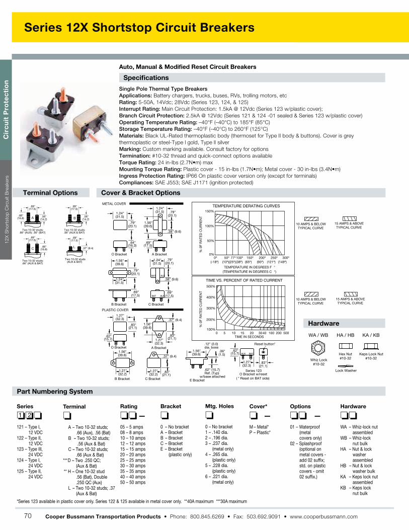
Series 12X Shortstop Circuit Breakers
Specifications
Single Pole Thermal Type BreakersApplications: Battery chargers, trucks, buses, RVs, trolling motors, etc
Rating: 5-50A, 14Vdc; 28Vdc (Series 123, 124, & 125)
Interrupt Rating: Main Circuit Protection: 1.5kA @ 12Vdc (Series 123 w/plastic cover);
Branch Circuit Protection: 2.5kA @ 12Vdc (Series 121 & 124 -01 sealed & Series 123 w/plastic cover)
Operating Temperature Rating: –40°F (–40°C) to 185°F (85°C)
Storage Temperature Rating: –40°F (–40°C) to 260°F (125°C)
Materials: Black UL-Rated thermoplastic body (thermoset for Type II body & buttons). Cover is grey
thermoplastic or steel-Type l gold, Type ll silver
Marking: Custom marking available. Consult factory for options
Termination: #10-32 thread and quick-connect options available
Torque Rating: 24 in-lbs (2.7N m) max
Mounting Torque Rating: Plastic cover - 15 in-lbs (1.7N m); Metal cover - 30 in-lbs (3.4N m)
Ingress Protection Rating: IP66 On plastic cover version only (except for terminals)
Compliances: SAE J553; SAE J1171 (ignition protected)
Auto, Manual & Modified Reset Circuit Breakers
Terminal Options
Hardware
.69"(17.5)
.69"(17.5)
.69"(17.5)
.56"(14.2)
.37" (9.4)
.56"(14.2)
.66"(16.8)
.66"(16.8)
Two 10-32 studs:.66" (AUX); .56" (BAT)
A
Two 10-32 studs:.56" (AUX & BAT)
B
Two 10-32 studs:.66" (AUX & BAT)
C
.69"(17.5)
Two 10-32 studs(AUX & BAT)
L
Cover & Bracket Options
Part Numbering System
1.24"(31.5)
1.27"(32.3)
1.27"(32.3)
1.24"(31.5)
1.24"(31.5)
1.24"(31.5)
1.27"(32.2)
1.27"(32.2)
1.56"(39.6)
1.56"(39.6)
.79"(20.1)
.79"(20.1)
.69"(17.5)
.69"(17.5)
.79"(20.1)
1.56"(39.6)
1.56"(39.6)
.64"(16.3)
.62"(15.7)
.69"(17.5)
.83"(21.1)
O Bracket
O Bracket
A Bracket
A Bracket
B Bracket C Bracket
B Bracket C Bracket
.38" (9.6)
.37" (9.4)
.79"(20.1)
.38" (9.6)
METAL COVER
PLASTIC COVER
.83"(21.1)
.37" (9.4)
.83"(21.1)
BAT AUX
BAT AUX
500%
500200100403020151050
400%
300%
200%
100%
TIME VS. PERCENT OF RATED CURRENT
TIME IN SECONDS
% 0
F R
ATE
D C
UR
RE
NT
150%
100%
50%
0%
% 0
F R
ATE
D C
UR
RE
NT
50º 77º100º 150º 200º 250º 300º0º(10º)(25º)(38º) (65º) (93º) (121º) (149º)(-18º)
TEMPERATURE IN DEGREES F °(TEMPERATURE IN DEGREES C °)
TEMPERATURE DERATING CURVES
10 AMPS & BELOWTYPICAL CURVE
15 AMPS & ABOVETYPICAL CURVE
10 AMPS & BELOWTYPICAL CURVE
15 AMPS & ABOVETYPICAL CURVE
1.56"(39.6)
E Bracket
Series 123O Bracket w/reset
1.27"(32.3)
.83"(21.1)
.62"(15.7)
.06"(1.5)
.12" (3.0)dia. boss
.62" (15.7)Ref. (Typ)
w/base attached
Reset button*
BATAUX
( * Reset on BAT side)
HA / HB
Hex Nut#10-32
Keps Lock Nut#10-32Whiz Lock
#10-32
Lock Washer
WA / WB KA / KB
Series
1 2
121 – Type I, 12 VDC
122 – Type II,12 VDC
123 – Type III,24 VDC
124 – Type I,24 VDC
125 – Type II,24 VDC
Terminal
A – Two 10-32 studs;.66 (Aux), .56 (Bat)
B – Two 10-32 studs;.56 (Aux & Bat)
C – Two 10-32 studs;.66 (Aux & Bat)
***D – Two .250 QC;(Aux & Bat)
** H – One 10-32 stud.56 (Bat), Double.250 QC (Aux)
L – Two 10-32 studs; .37(Aux & Bat)
Rating
–05 – 5 amps08 – 8 amps10 – 10 amps12 – 12 amps15 – 15 amps20 – 20 amps25 – 25 amps30 – 30 amps35 – 35 amps40 – 40 amps50 – 50 amps
Bracket
0 – No bracketA – BracketB – BracketC – BracketE – Bracket
(plastic only)
Mtg. Holes
0 – No bracket1 – .140 dia.2 – .196 dia.3 – .237 dia.
(metal only)4 – .265 dia.
(plastic only)5 – .228 dia.
(plastic only)6 – .221 dia.
(metal only)
Cover*
–M – Metal*P – Plastic*
Options
–01 – Waterproof
(metalcovers only)
02 – Splashproof(optional onmetal covers -add 02 suffix;std. on plasticcovers - omit02 suffix.)
Hardware
WA – Whiz-lock nutassembled
WB – Whiz-locknut bulk
HA – Nut & lockwasherassembled
HB – Nut & lockwasher bulk
KA – Keps lock nutassembled
KB – Keps locknut bulk
*Series 123 available in plastic cover only. Series 122 & 125 available in metal cover only. **40A maximum ***30A maximum
Cir
cu
it P
rote
cti
on
12
X S
ho
rtsto
p C
ircu
it B
reakers
Cooper Bussmann Transportation Products 70

Series 25X Mid-Range Circuit Breakers
Specifications
Single Pole Thermal Type BreakersApplications: This unit is external ignition protected and weatherproof. It is typically used in DC power
systems in marine applications (as a main or branch circuit breaker), truck, bus and RV systems, add-on
protection for accessories, etc
Rating: 10-50A, 32Vdc
Interrupt Rating: Circuit Protection (2.5kA) per ABYC E-11
Operating Temperature Rating: –40°F (–40°C) to 185°F (85°C)
Storage Temperature Rating: –40°F (–40°C) to 260°F (125°C)
Materials: Black UL-rated 94V0 thermoset plastic body. Cover, lever, and button are ULRated 94V0
thermoplastic. Cover has a black thermoplastic elastomer overmold
Marking: Standard marking includes amp/volt ratings, part numbers, and “SAE Type B”
Termination: #10-32 Threaded studs
Torque Rating: 24 in-lbs (2.7N m) max
Mounting Torque Rating: Panel mount with either #8-32 threaded inserts or #10 clearance holes. 18 in-lbs
(2.0N m) max
Ingress Protection Rating: IP66
Features / Options: Series 254 & 255 have a unique reset mechanism which provides a visual indication of
tripped condition. Series 255 also features a push-to-trip option
Compliances: SAE J553; ABYC E-11; SAE J1171 (ignition protected)
Auto, Manual & Modified Reset Circuit Breakers
Dimensions - mm(in)
Part Numbering System
TRIP TIME VS. PERCENT OF RATED CURRENT
% OF RATED CURRENT
100% 200% 300% 400% 500% 600%
1000
100
10
1
0.1
TIM
E IN
SEC
ON
DS
-40 -20 0 20 40 60 80AMBIENT TEMPERATURE IN DEGREE C
TEMPERATURE DERATING CURVE
200
150
100
50
0
MA
XIM
UM
% H
OLD
CU
RR
ENT
(2) #10-32 CLEARANCE HOLEOR #8-32 CLEARANCE HOLEIF USING THREADED INSERTS
Ø31.75 [Ø1.25]
19.99 [0.787]39.98
[1.574]21.50
[0.85]
RESET LEVER (series 254 & 255)
#10-32 EXTERNAL THREAD
MOUNTING OPTIONS
(255 series) TRIP BUTTON
27.80 [1.09]
5.00 [0.20]
33.80 [1.33]
18.50 [0.73]
39.98 [1.57]
17.33 [0.68]
55.73 [2.19]
37.00 [1.46]
(Dims. shown are for reference only. Consult factory for latest prints)
Series
2 5Rating
–10 – 10 amps15 – 15 amps20 – 20 amps25 – 25 amps30 – 30 amps35 – 35 amps40 – 40 amps50 – 50 amps
Mounting Holes
–A – Thru-hole Insert (#10 Clearance)B – #8-32 Threaded Inserts
Hardware
0 – No nuts1 – Nuts Installed2 – Nuts bulk
251 – Type I, 32V254 – Type III, 32V255 – Type III w/push-
to-trip option, 32V
Circ
uit P
rote
ctio
n2
5X
Mid
-Ran
ge C
ircu
it Bre
akers
Cooper Bussmann Transportation Products 71

Series 18X Hi-Amp Circuit Breaker
Specifications
Single Pole Thermal Type BreakersApplications: Typically used in auxiliary and accessory circuits in truck, bus’, RVs and marine
systems. Others include battery chargers and DC audio systems. Series 181, 184 & 185 are sealed
for engine compartment and bilge area applications.
Rating: 25-150A, 30Vdc; 42Vdc Nom (Series 184 & 185)
Interrupt Rating: 3000A @ 30Vdc
Operating Temperature Rating: -40˚C to +85˚C
Storage Temperature Rating: –30°F (–34°C) to 300°F (149°C)
Materials: Black UL-rated 94V0 thermoset plastic. Thermoplastic elastomer stud insulators are
provided on covered units with F-style (surface-mount) bases
Marking: Standard marking includes amp ratings and part numbers. Custom markings also
available.
Termination: 1/4-28 threaded studs
Torque Rating: 50 in-lbs (5.6N m) max
Mounting Torque Rating: Panel or surface-mount options; 50 in-lbs (5.6N m) max. Threaded
insert option has a max torque of 25 in-lbs (2.8N m).
Ingress Protection Rating: IP67
Features / Options: Series 184 & 185 have a unique reset mechanism which provides visual
indication of tripped condition. Series 185 also features a push-to-trip option
Compliances: SAE J1625; ABYC E-11; CE; SAE J1171 (ignition protected)
Auto, Manual & Switchable Reset Circuit Breakers
Dimensions - in(mm) (Dims. shown are for reference only. Consult factory for latest prints)
RESET
1.05(26.67)
2.23(56.64)
2.89(73.41)
1.44(36.58) 1.79
(45.47)
.66(16.76)
1.09*(27.69)
.40 (10.16)
1.90(48.26)Stud insulators
.26 (6.60) dia.Mtg.holes (2)
Reset lever(Shown inoperating
position series184/185)
.26 (6.60) dia. Mtg.holes (2)
Reset lever(Shown tripped)
1/4-28 Studs
Molded cover
Molded cover
*Overall heights of Series 181 &183
Trip button (Series 185)
.57(14.49)
1.06(26.92)
.31 (7.87)
.89 (22.61)
1.44*(36.58)
Tamper proofcover1.90
(48.26)
2.91(73.91)
2.41(61.21)
1.54(39.12)
Surface Mount Panel Mount
600%
500%
500200100403020151050
400%
300%
200%
200%
150%
100%
50%
0%
100%
TIME VS. PERCENT OF RATED CURRENT
TIME IN SECONDS
% 0
F R
ATE
D C
UR
RE
NT
% 0
F R
ATE
D C
UR
RE
NT
-50º 50º 77º 100º 150º 200º 250º0º(-45º) (10º)(25º)(38º) (65º) (93º) (121º)(-18º)
TEMPERATURE IN DEGREES F °(TEMPERATURE IN DEGREES C °)
TEMPERATURE DERATING CURVES
Flange mountgasket forthru-wall
applications(option 07)
Part Numbering System
Series
1 8
181 – Type I, 30V183 – Type I*, 30V184 – Type III, 42V185 – Type III-PTT, 42V
Rating
025 – 25 amps030 – 30 amps035 – 35 amps040 – 40 amps050 – 50 amps060 – 60 amps070 – 70 amps080 – 80 amps090 – 90 amps100 – 100 amps110 – 110 amps120 – 120 amps135 – 135 amps150 – 150 amps
Mounting
– –F – Surface MountP – Panel Mount
Terminal Hdwr.
00 – Ship w/o nuts01 – Sems nuts installed02 – Sems nuts shipped bulk03 – Stainless Steel Std. nuts &
washers installed04 – Stainless Steel Std. nuts &
washers shipped bulk07 – Flange gasket & Sems nuts installed
(Panel Mount Only)08 – Threaded insert and Sems nuts
installed12 – Stainless steel nuts and lockwashers
installed13 – Stainless steel Sems nut installed
Marking
0 – Blank cover1 – Standard Marking; Part Number,
Amp Rating181, 184, 185 Series - Top Surface183 Series - Side Surface
S – Standard Ignition ProtectedMarking
(Consult factory for special markings.)
*183 Available in PanelMount Only (Coverless)
Cir
cu
it P
rote
cti
on
Series 1
8X
Hi-
Am
p C
ircu
it B
reaker
Cooper Bussmann Transportation Products 72

Series 187 Marine Rated Circuit Breaker (MRCB)
Specifications
Single Pole Thermal Type BreakersApplications: Typically used in DC power systems in marine applications (as a main or
branch circuit breaker), truck and bus systems, RV systems, add-on protection for
accessories, lift gates, etc. This unit is external ignition protected and weatherproof.
Rating: 25-200A, 48Vdc
Interrupt Rating: Main Breaker Protection Interrupt Rating (5kA@ 12Vdc). (Consult factory for
higher voltage interrupt ratings.)
Operating Temperature Rating: –40°F (–40°C) to 185°F (85°C)
Storage Temperature Rating: –40°F (–40°C) to 260°F (125°C)
Materials: Black UL-rated 94V0 thermoset plastic body. Cover and lever are UL-rated 94V0
thermoplastic
Marking: Standard marking includes amp/volt ratings. Custom markings also available
Termination: 5/16-18 threaded studs
Torque Rating: 75 in-lbs (8.5N m) max
Mounting Torque Rating: Panel or surface-mount options; 50 in-lbs (5.6 N m) max
Ingress Protection Rating: IP66
Features / Options: A manual reset circuit breaker with On-Off switch capability
Compliances: ABYC E-11; CE; SAE J1171 (ignition protected)
Consult factory for time characteristic curves.
Manual Reset Circuit Breakers With Switch Function
Dimensions - mm(in)
Part Numbering System
(Dims. shown are for reference only. Consult factory for latest prints)
R
MRCBBUSS
TRIPOFF
RESET
48V DC MAX
25A
IGNITION PROTECTEDWEATHERPROOF
69.85 [2.750]
28.84 [1.135]
ON 16.76 [.660]
26.81 [1.056]
53.47 [2.105]
57.68 [2.271]
(2.24)56.8
(2.32)59.0
(1.06)27.1
(1.64)41.6
( .72)43.8
( 2.72)69.0
(.16)3.9
(1.46)37.1
(.73)18.6
(3.44)87.3
60.34 [2.375]
58.15 [2.289]
MRCB
25A48V DC MAX
WEATHERPROOF
IGNITION PROTECTED
RESET
BUSS
OFF
ON
Panel Mount
Mounting Template
Firewall Mount
Series
1 8 7
187 – Manual Reset - SwitchingStyle Circuit Breaker
Rating
025 – 25 amps030 – 30 amps035 – 35 amps040 – 40 amps050 – 50 amps060 – 60 amps070 – 70 amps080 – 80 amps100 – 100 amps110 – 110 amps120 – 120 amps135 – 135 amps150 – 150 amps200 – 200 amps
Mounting
–F – Surface mountP – Panel mount
Hardware
–00 – No hardware03 – Stainless nuts &
lockwashers - installedon studs
04 – Stainless nuts & lockwashers - suppliedbulk packed
Marking
1 – Standard marking; Part Number,Amp Rating
(Consult factory for special marking options.)
0 5 10 15 20 30 40 50 100 150 200 400 600
600%
500%
400%
300%
200%
100%
Time vs Percent of Rated Current
Time in seconds
Temperature Derating Curves
Temperature in Degrees F.
-50˚ F 0˚ F 50˚ F 77˚ F 100˚ F 150˚ F 200˚ F 250˚ F0%
50%
100%
150%
200%
Circ
uit P
rote
ctio
nS
erie
s 1
87
MR
CB
Cooper Bussmann Transportation Products 73

AMI Series
16
40
.84
8.2
4.1
12
12
R 1.6
30
Time-Current Specifications30A …….. 125A 150A ……. 200A
% OF RATING Min. Max. Min. Max.
75% -- -- 360.000s �100% 360.000s � -- -- 110% 14.400s � -- -- 150% 90s 3.600s -- -- 200% 3s 100s 1s 15s 300% 0.3 3s -- -- 350% -- -- 0.3s 5s 500% 0.1 1s -- -- 600% -- -- 0.1s 1s
[In%]
100%In >
360.000s
110%In >14.400s
3.600 sec.150%
3 sec.
360.000 sec.
1 sec.
14.400sec.
90 sec.
3 sec.
0,1 sec.
250%
0,3 sec.
100 sec.
0%
200%
300%
400%
500%
600%
0.01
110%100%
0.1 1 10 100 1000 10000 100000 [s] 1000000
LMI3-M-2-A1L IFH-AMI-M5 (or M6)
Holders
Time-Current Curve
Series Rating
030 – 30 amps (orange)040 – 40 amps (green)050 – 50 amps (red)060 – 60 amps (yellow)070 – 70 amps (brown)080 – 80 amps (white)100 – 100 amps (blue)125 – 125 amps (pink)150 – 150 amps (gray)175 - 175 amps (light brown)200 - 200 amps (violet)
Dimensions - mm (Dims. shown are for reference only. Consult factory for latest prints)
Bolt In Automotive Fuses
Specifications
Applications: Power distribution protection for
automotive systems. Fuse holder shown on right.
Current Rating: 30-200A
Voltage Rating: 32Vdc
Interrupt Rating: 2000A @ 32Vdc; 5000A@ 16Vdc
Housing Material: UL-rated 94V0 thermoplastic
Terminal Material: Tin-plated brass
Mounting: Max torque of 35 in-lbs (4N m)
Marking: Color-coded housings for each amperageCompliances: SAE J1171 (ignition protected); ISO 8820-5
Part Numbering System
A≤125A >125A
Hole for a bolt diameter of M5 and/or M6 Hole for a bolt diameter of M6
A
(Available for up to 6 fuses) (Single Fuse Only)
B K - A M I
Cooper Bussmann Transportation Products
Cir
cu
it P
rote
cti
on
AM
I S
eries
74

AMG Series
Dimensions - mm(in)
Time-Current Curves
Time-Current Specifications
Bolt In Automotive Fuses
Part Numbering System
Applications: For high current applications. Use with Cooper
Bussmann HMG or FMG fuseholders. (See pages 48-49.)
Current Rating: 100-300A.
Voltage Rating: 32Vdc*
Interrupt Rating: 1,000A @ 32Vdc
Housing Material: UL-rated 94V0 thermoplastic
Terminal Material: Copper
Mounting: M8 or 5/16-18 or less studs on 2.00 in (50.8mm) centers
Max torque of 8.1 to 9.6 ft-lbs (12 ±1N m)
Marking: Color-coded amperage ratings
Compliances: SAE J1171 (ignition protected), ISO 8820-5
*Consult factory for higher voltage fuses.
Series Rating
100 – 100 amps125 – 125 amps150 – 150 amps175 – 175 amps200 – 200 amps225 – 225 amps250 – 250 amps300 – 300 amps400 – 400 amps
68.40(2.693)
29.20(1.150)
1.52(0.06)
9.00(0.354)
29.20(1.150)
15.40(0.606)
50.80(2.000)
12.18(0.480)
Ø8.60(0.339)
150
175
200
250
% of
Rating
80A-250A 300A-500A
Min. Max. Min. Max.
75%
100%
135%
200%
350%
600%
4 hrs
120s
1s
0.3x
0.1s
∞
1800s
15s
5s
1s
1s
0.5s
0.1s
15s
5s
1s
4 hrs ∞- - - -
- - - -
- - - -
500 - 500 amps
AmpRating
Current in Amps
B K - A M G
Cooper Bussmann Transportation Products
Circ
uit P
rote
ctio
nA
MG
Serie
s
75

Marine Rated Battery Fuse
Specifications
Operating Times
CF Cover
CF Bar
Designed for the most demanding environment to provide high current
protection for the tightest space constraints. Suitable for main and
auxiliary circuit protection such as alternator outputs, starter motor
inputs and accessory circuits. The breaking capacity meets the
requirements of conventional vehicle batteries and 12V, 24V and 42V
electrical networks.
About MRBF-XXX Series Marine Rated Battery Fuse
Rating
30A - 300A
100%
> 100 h
135%
Max 900 sec
200%
max.
60s
350%
min. max.
0.1s 1 s
600%
< 0.2s
Applications: Full range circuit protection for automotive and marine
applications. Break in capacity meets the requirements of conventional
vehicle batteris and 42V electrical networks
Voltage Rating: 58Vdc Maximum
Amperage Rating: 30A - 300A
Ingress Protection: IP66
Ignition Protected: Per SAEJ1117
Interrupt Rating:
10000 AMP @ 14Vdc
5000 AMP @ 32Vdc
2000 AMP @ 58Vdc
Color Coded (see next page)
Torque Rating: Maximum 12 N m (106 in-lbs)
Material:
Body - Ceramic
Housing & Cover: UL-rated 94V0 Thermoplastic
Ring Terminals - Tin Plated
Compliances: ISO 8820-6
Cooper Bussmann Transportation Products
Cir
cu
it P
rote
cti
on
Marin
e R
ate
d B
att
ery
Fu
se
76

Marine Rated Battery Fuse
MRBF Dimensions - mm(in) Part Numbering System
CF Cover Dimensions - mm(in)
23.0 REF(0.91)
27.8(1.09)
BUSS
58V
XXXA
. XXX
Fuse Amperages
MRBF - X X X
030 - 30 AMPS [ LT GREEN ]040 - 40 AMPS [ LT BLUE ]050 - 50 AMPS [ RED ]060 - 60 AMPS [ GOLD ]075 - 75 AMPS [ BROWN ]080 - 80 AMPS [ LIME ]090 - 90 AMPS [ PURPLE ]100 - 100 AMPS [ YELLOW ]125 - 125 AMPS [ GREEN ]150 - 150 AMPS [ ORANGE ]175 - 175 AMPS [ WHITE ]200 - 200 AMPS [ BLUE ]225 - 225 AMPS [ TAN ]250 - 250 AMPS [ PINK ]300 - 300 AMPS [ GREY ]
58.3(2.29)
22.0(0.87)
6.0(0.24)
BUS BAR STUD COVER-SINGLE BUS BAR STUD COVER-DOUBLE
22.0(0.87)
6.0(0.24)
82.2(3.24)
CF Bar Dimensions - mm(in)
20.0(.79)
12.0(.47)
2.5(0.10)
88.5(3.48)
56.5(2.22)
2.5(.10)
61.9(2.44)
30.0(1.18)
11.0(.43)
15.5(.61)
20.0(.79)
12.0(.47)
“B”“See Table”
“A”“See Table”
Laser Markingon Surface
“A”“See Table”
Laser MarkingOn Surface
Material and Finish Table
Part Number
CFCOVER-XB
CFCOVER-XR
MATERIAL
SANTOPRENE
SANTOPRENE
COLOR
BLACK
RED
Part #
CFBAR1 - 250SP
CFBAR1 - M8XSP
CFBAR1 - 250BP
CFBAR1 - M8XBP
CFBAR2 - 250SP
CFBAR2 - M8XSP
CFBAR2 - 250BP
CFBAR2 - M8XBP
DIM. “A”
44.5 [1.75]
46.5 [1.83]
44.5 [1.75]
46.5 [1.83]
44.5 [1.75]
46.5 [1.83]
44.5 [1.75]
46.5 [1.83]
DIM. Ø “B”
10.3 [0.405]
10.3 [0.405]
13.5 [0.531]
13.5 [0.531]
10.3 [0.405]
10.3 [0.405]
13.5 [0.531]
13.5 [0.531]
Table:
CFBARX - XXXXP
1 - Single Stud2 - Double Stud
250 - 1/4-20 studM8X - M8 stud
S - 3/8” Mounting HoleB - 1/2” Mounting Hole
CFCOVER-XX
Cover ColorB - BlackR - Red
Stud1 - Single Stud2 - Double Stud
Ø “B”“See Table”
Cooper Bussmann Transportation Products
Circ
uit P
rote
ctio
nM
arin
e R
ate
d B
atte
ry F
use
77

Series 15250
Dimensions - mm(in) (15250-1b Shown)
Specifications
Options
Part Numbering System
Battery Disconnect Switch
Applications: A non-fused current interrupt disconnect designed for
opening the circuit between a battery and the complete electrical load of a
battery-powered system.
Rating: 400A continuous,. 50Vac/Vdc. Vehicle cranking and max. surge
currents to 2000A (based on 20% duty cycle with ON times of 5 seconds
max.).
Temperature Rating: –40°F (–40°C) to 150°F (65°C).
Termination: 1/2-13 Copper alloy stud.
Torque Rating: 420 in-lbs (47.5N m) max.
Mounting Torque Rating: With mounting brackets: 48 in-lbs (5.4N m)
max; without mounting brackets: 10 in-lbs (1.1N m) max.
Handles: Three handle styles available.
Other: Lubricant-filled body with silicone sealant.
Series
–1 5 2 5 0
BracketOption
Lubricantw/Sealant
L R
HandleOption
123
B – Bracket (Grease Filled)
ON
ON
OFF
(3.81)96.8
(1.56)39.7
(1.12)28.4
(.50)12.7
(2.75)69.8
Point A
(5.5)139.7
(7.0)177.8
(8.0)203.2
(4.19)106.4
(3.5)88.9
(3.0)76.2
(.59)15.1
(4.87)123.8
(2.44)61.9
(1.25)31.7
(3.12)79.4
Ref. Point A
Ref. Point A
Ref. Point A
(3.00)76.2
(4.50)114.3
15250-1
15250-2
15250-3
1/2-13 Copper alloy stud
Stainless washers and locknuts supplied
Handle Variations
(Dims. shown are for reference only. Consult factory for latest prints)
Ref.
Cooper Bussmann Transportation Products
Cir
cu
it P
rote
cti
on
Series 1
52
50
78

Circuit Protection Notes
Circ
uit P
rote
ctio
nN
ote
s
Cooper Bussmann Transportation Products 79

Mobile Vehicle Controls
Cooper Bussmann Transportation Products
Off-the-shelf and custom-designed
products for the distribution of I/O,
on-chassis communication and remote
vehicle control
Distributed I/O
Radio Remote ControlCAN (J1939)
interfaces
80
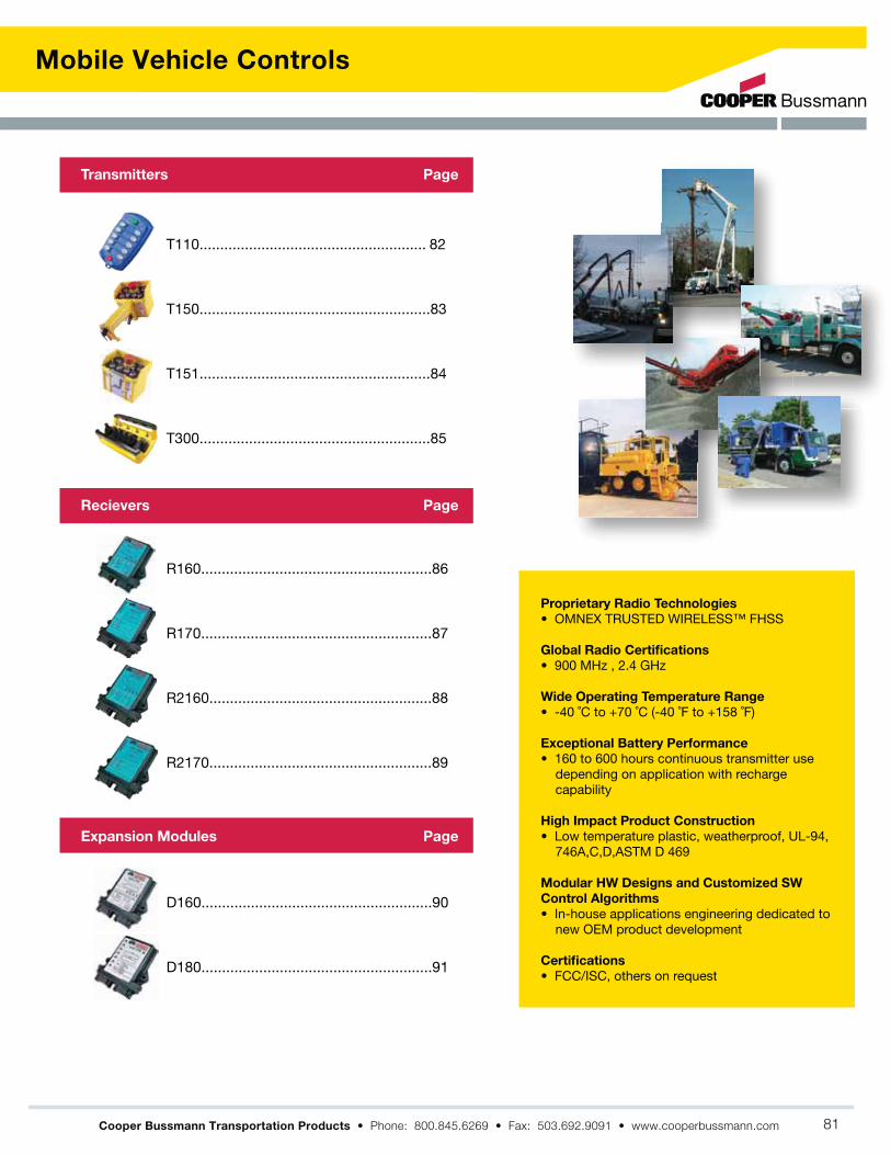
Mobile Vehicle Controls
Cooper Bussmann Transportation Products
Proprietary Radio Technologies
Global Radio Certifications
Wide Operating Temperature Range
Exceptional Battery Performance
High Impact Product Construction
Modular HW Designs and Customized SW
Control Algorithms
Certifications
Transmitters
Recievers
Expansion Modules
Page
Page
Page
81

T110 Transmitter
Cooper Bussmann Transportation Products
Features
Applications
Specifications Options
Accessories
The T110 will work with the following recievers
Operator Keys:
Security:
Input Power:
Battery Life:
Operating Temperature Range:
Size:
Weight:
Construction:
Frequency:
Antenna:
Approvals/Certificates:
Specifications subject to change without notice
Mo
bil
e V
eh
icle
Co
ntr
ols
82

T150 Transmitter
Features
Applications
Specifications Options
Accessories
The T150 Will Work With The Following Recievers
The ORIGA T150 transmitter is a hand-held, user friendly radio remote control that
comes with a Hall Effect proportional trigger designed for smooth operation.
Weatherproof and lightweight, the ORIGA T150 can be configured to include a
resettable E-Stop switch. The T150 uses OMNEX's Trusted Frequency Hopping
Spread Spectrum technology to provide reliable performance even in the harshest
environments.
Operator Keys: 14 Functions + E-Stop One
proportional trigger
Indicators& Diagnostics:
Security:
CRC-16 error detection
Input Power:
Battery Life:
Operating Temperature Range: -40 °F to 158 °F
Size:
Weight:
Construction: HigHigh impact, low temperature plastic,
Frequency:
Antenna: Internal
Approvals/Certificates:
Specifications subject to change without notice
R160 - 19 I/O
Portable 14-Function Radio Remote Control
Global applications
applications
4 switch - 8 digital outputs +
optional proportional trigger
5 switch - 10 digital outputs +
optional proportional trigger
7 switch - 14 digital outputs +
optional proportional trigger
5 switch - 10 digital outputs +
proportional dial + optional
proportional trigger
Magnet
Pendant Cable
Cooper Bussmann Transportation Products
Mo
bile
Ve
hic
le C
on
trols
T1
50
Tra
nsm
itter
83

T151 Transmitter
Features
Applications
SpecificationsOptions
Accessories
The T151 will work with the following recievers
The OMNEX ORIGA T151 transmitter is a configurable, license-free radio remote
control. With up to 5 switches and a potentiometer, this transmitter can accommodate
both digital and proportional controls. The ORIGA T151 is a flexible, compact, light
weight transmitter providing the user the ability to customize the remote for their
unique needs. Using OMNEX's Trusted Frequency Hopping Spread Spectrum
technology, this remote delivers superior performance and reliability under the
toughest conditions.
Operator Keys: 14 Functions + E-Stop one
proportional dial.
Indicators& Diagnostics:
Security:
CRC-16 error detection
Input Power:
Battery Life:
Operating Temperature Range: -40 °F to 158 °F
Size:
Weight:
Construction: High impact, low temperature plastic,
Frequency: 902 to 928MHz - ISM band
2.4 - 2.483GHz - ISM band
Antenna: Internal
Approvals/Certificates: USA - FCC Part 15.247
Canada - ISC RSS 210
RF Approval EN 300 440
Specifications subject to change without notice
R160 - 19 I/O
Portable 14-Function Radio Remote Control
Global applications
applications
4 switch - 8 digital outputs +
optional proportional dial
5 switch - 10 digital outputs +
optional proportional dial
7 switch - 14 digital outputs +
optional proportional dial
5 switch - 10 digital outputs +
proportional dial + optional
proportional dial
Magnet
Pendant Cable
Cooper Bussmann Transportation Products
Mo
bil
e V
eh
icle
Co
ntr
ols
T1
51
Tra
nsm
itte
r
84

T300 Transmitter
Features
Applications
Specifications
Options
Accessories
The T300 will work with the following recievers
The ORIGA T300 is an easy to use weatherproof transmitter with up to 16 proportional
functions and 15 digital functions. The T300 can accommodate eight single axis
paddles or four dual axis joysticks; and up to eight three-position switches and a
re-settable E-Stop, giving the user a wide variety of customizable configurations to
choose from. A unique ID code is used by each T300 to ensure that no two systems
will conflict on a job site and the incorporation of OMNEX's Trusted Frequency
Hopping Spread Spectrum technology ensures that the T300 will provide reliable
performance even in the harshest environments.
Operator Keys: 31 Functions + E-Stop up to eight
proportional paddles
Indicators & Diagnostics: BATTERY/PENDANT,
Security: Factory programmed with unique ID code.
CRC-16 error detection
Input Power: 4C (alkaline) Batteries
Battery Life: 500 Hours
Operating Temperature Range: -40 °F to 158 °F
(-40 °C to 70 °C)
Size: 9.5” x 6.0" x 5.0”(240mm x 152mm x 127mm)
Weight: 3.5lbs (1.6kg)
Construction: High impact, low temperature plastic,
Frequency: 902 to 928MHz - ISM band
2.4 - 2.483GHz - ISM band
Antenna: Internal
Approvals/Certificates:
Canada - ISC RSS 210
Specifications subject to change without notice
R160 - 19 I/O
R170 - CANbus (J1939)
Portable 31-Function Radio Remote Control
batteries
(900 ft. @ 2.4 GHz)
applications
Expansion Modules:
D160 - 19 I/O
D180 - 14 proportional outputs
As shown:
6 switch - 11 digital funtions +
2 paddles - 4 proportional functions
2 joysticks - 8 proportional functions
Shoulder Strap Pendant Cable
Cooper Bussmann Transportation Products
Mo
bile
Ve
hic
le C
on
trols
T3
00
Tra
nsm
itter
85

R160 Remote Control Reciever
Features
Applications
Compatible Transmitters
Accessories
Specifications
The OMNEX Trusted Wireless™ R160 receiver is a robust, license-free logic controller &
valve driver designed for smooth operation and precise control of industrial machinery in
global applications. The R160 receiver features 19 I/O combinations (more can be
achieved with expansion modules) and is fully customizable to operate momentary,
latched, toggled and interlocked functions. Depending on the application, the R160 can
provide digital and analog (current, voltage and PWM output) signals and an electronic
output for the safe shutdown of power to the outputs and external circuits. When used
with the T110C, the system is field configurable. Each R160 uses a unique ID code to
ensure no two systems will conflict on a job site and OMNEX trusted Frequency
Hopping Spread Spectrum technology to provide reliable performance and relentless
control even in the harshest environments.
Outputs: 19 digital functions (with up to 4 proportional)
Inputs: 19 (outputs can act as inputs)
Indicators & Diagnostics:
Security: ID code programmed from transmitter,
CRC-16 error detection
Power: 9 - 32Vdc
Operating Temperature Range: -40 °F to 158 °F
(-40 °C to 70 °C)
Size: 5.1" x 4.7” x 1.4" (130mm x 119mm x 36mm)
Weight: .651bs (295g)
Construction: High impact plastic, weatherproof
Frequency: 902 to 928MHz - ISM band &
2.4 - 2.483GHz - ISM band
Antenna Connector: Internal or external (optional)
Approvals/Certificates:
R160 - USA - FCC Part 15 Class B
Canada - ISC RSS 210
European Union - CE
Specifications subject to change without notice - E&OE
19-Function Remote Controlled Reciever
The R160 will work with the following
Expansion Modules
D160 - 19 I/O
D180 - 14 proportional outputs
T110 - 10 (20) -Function
Hand-Held Radio
Remote Control
T150 - 14-Function
Hand-Held Radio
Remote Control
T300 - 31-Function Radio
Remote Control
Pendant Cable
(optional with T150 or T300)
External Antenna Output Cable
Cooper Bussmann Transportation Products
Mo
bil
e V
eh
icle
Co
ntr
ols
R1
60
Recie
ver
86

R170 CANbus Reciever
Features
Applications
Compatible Transmitters
Accessories
Specifications
The OMNEX Trusted Wireless™ R170 receiver is a robust, license-free logic controller
and valve driver designed for smooth operation and precise control of industrial
machinery in global applications. The R170 receiver is designed for CAN bus protocols
and includes an electronic output function, allowing for safe shutdown of power to the
outputs and external circuits. This receiver is compatible with SAE J1939 protocol and
can be customized to work with other CAN bus protocols. As well, it has an RS232 port
for configuration, diagnostics and firmware upgrades. Each R170 uses a unique ID code
to ensure no two systems will conflict on a job site and OMNEX trusted Frequency
Hopping Spread Spectrum technology to provide reliable performance and relentless
control even in the harshest environments.
Outputs:
Inputs: CAN bus (J1939)
Indicators & Diagnostics:
Security: ID code programmed from transmitter.
CRC-16 error detection
Power: 9 - 32VDC
Operating Temperature Range:
Size:
Weight:
Construction: High impact plastic, weatherproof
Frequency:
Antenna Connector: Internal or external (optional)
Approvals/Certificates:
Canada - ISC RSS 210
Specifications subject to change without notice - E&OE
The R170 will work with the following
Expansion Modules
T110 - 10 (20) -Function
Hand-Held Radio
Remote Control
Hand-Held Radio
Remote Control
T300 - 31-Function Radio
Remote Control
Pendant CableExternal Antenna Output Cable
Cooper Bussmann Transportation Products
Mo
bile
Ve
hic
le C
on
trols
R1
70
Recie
ver
87

R2160 Two-Way Remote Control Receiver
FEATURES
APPLICATIONSSPECIFICATIONS
The OMNEX Trusted Wireless™ R2160 receiver is a robust , license-free logic
controller and valve driver designed for smooth operation and precise control of
industrial machinery in global applications. The R2160 receiver features 19 1/0
combinations (more can be achieved with expansion modules) and is fully
customizable to operate momentary, latched, toggled and interlocked functions.
2-Way communication provides the operator with machine and diagnostic feedback.
Depending on the application, the R2160 can provide digital and analog (current,
voltage and PWM output) signals and an electronic output for the safe shutdown of
power to the outputs and external circuits. Each R2160 uses a unique ID code to
ensure no two systems will conflict on a job site and OMNEX trusted Frequency
Hopping Spread Spectrum technology to provide reliable performance and relentless
control even in the harshest environments.
Outputs: 19 digital functions (with up to 4 proportional)
Inputs: 19 (outputs can act as inputs)
Indicators & Diagnostics:
Security:
Power: 9 - 32Vdc
Operating Temperature Range: -40 °F to 158 °F
Size:
Weight: .65 lbs (295g)
Construction: High impact plastic, weatherproof
Frequency: 902 to 928MHz - ISM band &
2.4 - 2.483GHz - ISM band
Antenna Connector: Internal or external (optional)
Approvals/Certificates:
Specifications subject to change without notice - E&OE
Cooper Bussmann Transportation Products
Mo
bil
e V
eh
icle
Co
ntr
ols
R2
16
0 R
ecie
ver
88

R2170 CANbus 2-Way Reciever
Features
Applications
Specifications
The OMNEX Trusted Wireless™ R2170 receiver is a robust, license-free logic controller
and valve driver designed for smooth operation and precise control of industrial
machinery in global applications. The R2170 receiver is designed for CAN bus protocols
and includes an electronic output function, allowing for the safe shutdown of power to
the outputs and external circuits. This receiver is compatible with SAE J1939 protocol
and can be customized to work with other CAN bus protocols. As well, it has an RS232
port for configuration, diagnostics and firmware upgrades. This receiver can act as a
CAN bridge with 2-Way communication capabilities, providing the operator with
machine and diagnostic feedback. Each R2170 uses a unique ID code to ensure no
two systems will conflict on a job site and OMNEX trusted Frequency Hopping Spread
Spectrum technology to provide reliable performance and relentless control even in the
harshest environments.
Outputs:
Inputs: CAN bus (J1939)
Indicators & Diagnostics:
Security: ID code programmed from transmitter,
CRC-16 error detection
Power: 9 - 32Vdc
Operating Temperature Range:
Size:
Weight:
Construction: High impact plastic, weatherproof
Frequency:
Antenna Connector: Internal or external (optional)
Approvals/Certificates:
Canada - ISC RSS 210
Specifications subject to change without notice - E&OE
Cooper Bussmann Transportation Products
Mo
bile
Ve
hic
le C
on
trols
R2
17
0 R
ecie
ver
89

D160 Expansion Module
Features
Applications
OMNEX Transmitters
Accessories
Specifications
The OMNEX D160 expansion module for the R160 receiver features 19 I/O
combinations (19 digital or 17 digital + 2 proportional outputs). The D160 is designed
to be powered from a 12Vdc or a 24Vdc system and is fully customizable to operate
momentary, latched, toggled and interlocked functions. When combined with the
R160, this pair will provide up to 34 digital and 4 proportional outputs.
Outputs: 19 digital functions (with up to 4 proportional)
Inputs: 19 (outputs can act as inputs)
Indicators & Diagnostics: Four status LEDs
Power: 9 - 32Vdc
Operating Temperature Range: -40 °F to 158 °F
(-40 °C to 70 °C)
Size: 5.1" x 4.7” x 1.4" (130mm x 119mm x 36mm)
Weight: .6lbs (270g)
Construction: High impact plastic, weatherproof,
Specifications subject to change without notice - E&OE
19-Function Expansion Module
The D160 will work with the following
Reciever:
R160 - 19 I/O
T110 - 10 (20) -Function
Hand-Held Radio
Remote Control
T150 - 14-Function
Hand-Held Radio
Remote Control
T300 - 31-Function Radio
Remote Control
Output Cable
Cooper Bussmann Transportation Products
Mo
bil
e V
eh
icle
Co
ntr
ols
D1
60
Exp
ansi
on M
odul
e
90

D180 Expansion Module
Features
Applications
OMNEX Transmitters
Accessories
Specifications
The OMNEX D180 expansion module for the R160 receiver features 14 proportional I/O
combinations (I/O can also be configured to operate digital functions). The D180 is
designed to be powered from a 12Vdc or a 24Vdc system. Depending on the
application, the D180 can provide digital and analog (current, voltage or PWM output)
signals. When combined with the R160, this pair will provide up to 19 digital and up to
18 proportional functions.
Outputs: 14 Proportional functions
Indicators & Diagnostics: Eight status LEDs
Power: 9 - 32Vdc
Operating Temperature Range: -40 °F to 158 °F
(-40 °C to 70 °C)
Size: 5.1" x 4.7” x 1.4" (130mm x 119mm x 36mm)
Weight: .65lbs (300g)
Construction: High impact plastic, weatherproof,
Specifications subject to change without notice - E&OE
14 - Proportional Function Expansion Module
The D180 will work with the following
Reciever:
R160 - 19 I/O
T110 - 10 (20) -Function
Hand-Held Radio
Remote Control
T150 - 14-Function
Hand-Held Radio
Remote Control
T300 - 31-Function Radio
Remote Control
Output Cable
Cooper Bussmann Transportation Products
Mo
bile
Ve
hic
le C
on
trols
D1
80
Exp
an
sio
n M
od
ule
91

Printed in USA
Power Management
Cooper BussmannSure Power10189 SW Avery St
Tualatin, OR 97062
Tel: 800-845-6269
Fax: 503-692-9091
Tech Support: 503.612.7103
Cooper BussmannTransportation Products10189 SW Avery St
Tualatin, OR 97062
Tel: 800-845-6269
Fax: 503-692-9091
Tech Support: 847.956.5558
Power DistributionCircuit Protection Radio Remote Control
Cooper BussmannOMNEX Control Systems74 - 1833 Coast Meridian Road
Port Coquitlam, BC
Canada V3C 6G5
Tel: 800-663-8806
Fax: 604-944-9267
Tech Support: 604.944.9247 #368
Cooper Bussmann Transportation Products Headquarters:
10189 SW Avery St.Tualatin, OR 97062Tel: 800-845-6269www.cooperbussmann.com
Cooper Bussmann Transportation
is a part of the
Cooper Industries world.
Visit us online at www.cooperbussmann.com
#7047 3-11-2M