copied from an original at the history center, diboll, … · adaptations of lufkin herringbone...
TRANSCRIPT
Copied from an original at The History Center, Diboll, TX. www.TheHistoryCenterOnline.com 2013:023
LUFKIN EQUIPMENT OF ADVANCED DESIGN
Copied from an original at The History Center, Diboll, TX. www.TheHistoryCenterOnline.com 2013:023
2
LUFKIN FOUNDRY & MACHINE CO. FACTORY AND GENERAL OFFICES
LUFKIN, TEXAS BRANCH OFFICES AND WAREHOUSES
GULF COAST DIVISION 806 2nd N at 'l Bank Bldg. Houston, Texas,
CALIFORNIA DIVISION Los Angeles, Calif., 5959 South Alameda
MID-CONTINENT DIVISION Tulsa, Okla., 1901 Philtower Bldg.
EXPORT DIVISION New York, N. Y., 149 Broadway, Cable address "LUFFO"
WAREHOUSES Odessa, Texas Beeville, Texas
EAST TEXAS DIVISION Henderson, Texas, Crim Crest Hill, P. 0. Box 516 Dallas, T exas
WAREHOUSES Seminole, Oklahoma
ARKANSAS-LOUISIANA DIVISION El Dorado, Arkansas
1504 Magnolia Bldg.
PRODUCTS:
Herringbone Geared Pumping Units Worm Geared Pumping Units Geared Central Pumping Powers Production Hoists Samson Posts
Walking Beams-Improved Pitmans-Trout Oil-bath Center Irons-Oil-bath and A. P. I. Trout Counterbalance Crank Rod Line Weights Improved Oil Field Equipment.
INDEX
LUFKIN OIL FIELD EQUIPMENT
Catalogue No. 33.
Users of Lufkin Equipment ...................... . .................................... .
Herringbone Unit Division ... . ......... . . . ... .. .. .. ........................... . ....... .
Worm Gear Unit Division .................. . ........................ . ................. .
Central Power Division .... . .......................................................... .
Trout Counterbalance Crank ............... · ....... . .................................... .
Unit Selection Guide ............................ . . .................................... .
Samson Post Assemblies .. . ........ . ............. . .................................... .
Walking Beams .................. . ............... . ..... ! .............................. .
Pitmans-Trout Oil-bath . ........................ . ................ . ............... .. .. .
Hoists .......................... ... .. . .......... . .................................... .
Pictorial Review ..................................................................... .
Branch Office Directory ... . ... . ..... ... ..... . ... .. ................... . ................ .
Plant Bird's Eye ... . . . . ... . . ...... . .. .. ...... . .. . .................... . .. : ............ .
Rod Line Weights .... . .. . . . .... . ............... .. .................................... .
Facts About Lufkin Equipment. ......... . ..... ... ........... . .. .. .................... .
Page 22
3 to 11 Incl.
12 to 13 Incl.
18 to 21 Incl.
9
10
14 to 15 Incl.
14 to 15 Incl.
15
17
8-11-21
2
2
17
16
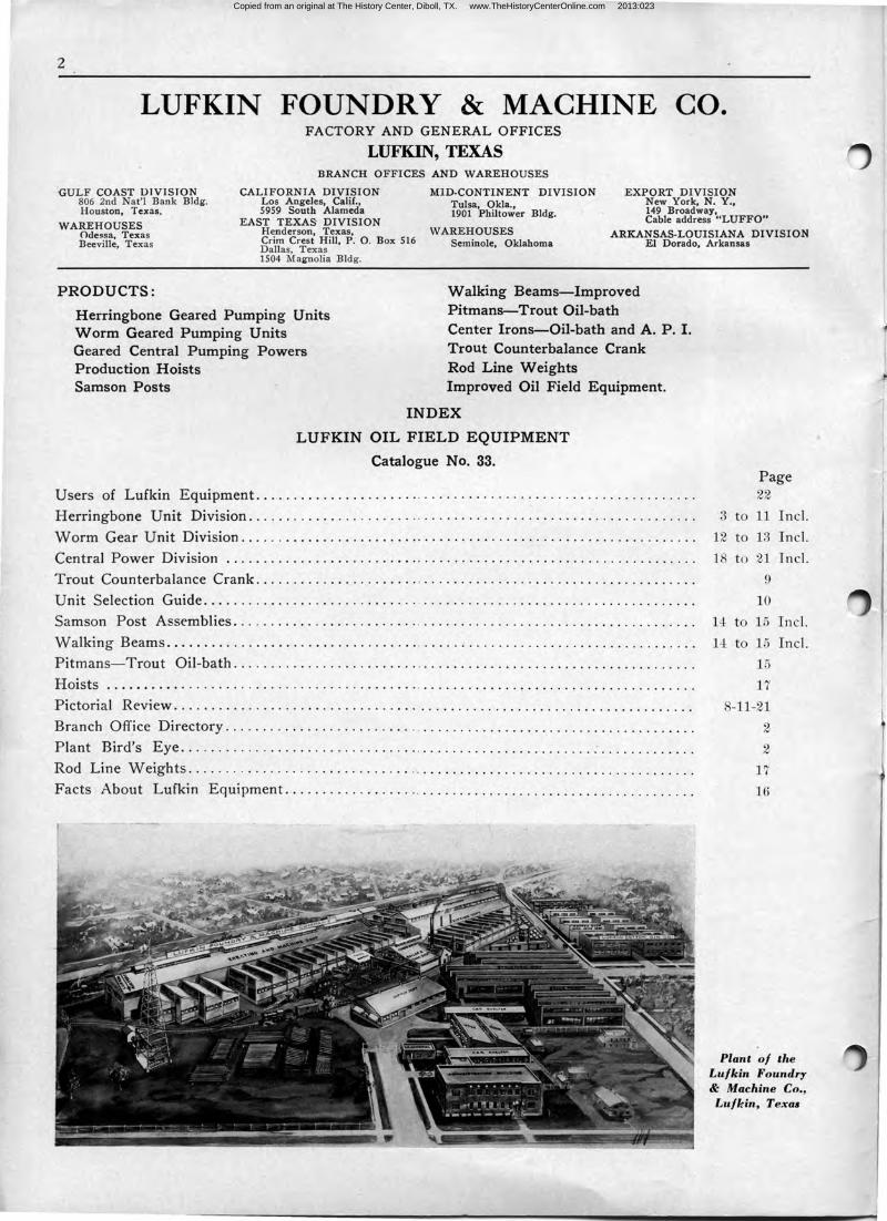
Plant of the Lufkin Foundry & Machine Co., Lufkin, Texas
Copied from an original at The History Center, Diboll, TX. www.TheHistoryCenterOnline.com 2013:023
3
LUFKIN FOUNDRY & MACHINE CO. LUFKIN, TEXAS
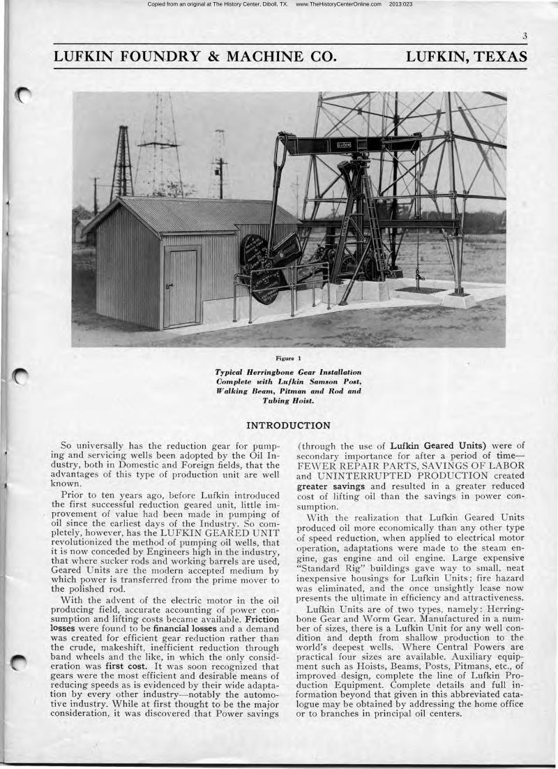
Figure 1
Typical Herringbone Gear Installation Oomplete with Lufkin Samson Post, Walking Beam, Pitman and Rod and
Tubing Hoist.
INTRODUCTION
So universally has the reduction gear for pumping and servicing wells been adopted by the Oil Industry, both in Domestic and Foreign fields, that the advantages of this type of production unit are well known.
Prior to ten years ago, before Lufkin introduced the first successful reduction geared unit, little improvement of value had been made in pumping of oil since the earliest days of the Industry. So completely, however, has the LUFKIN GEARED UNIT revolutionized the method of pumping oil wells, that it is now conceded by Engineers high in the industry, that where sucker rods and working barrels are used, Geared Units are the modern accepted medium by which power is tr an sf erred from the prime mover to the polished rod.
With the advent of the electric motor in the oil producing field, accurate accounting of power consumption and lifting costs became available. Friction losses were found to be financial losses and a demand was created for efficient gear reduction rather than the crude, makeshift, inefficient reduction through band wheels and the like, in which the only consideration was first cost. It was soon recognized that gears were the most efficient and desirable means of reducing speeds as is evidenced by their wide adaptation by every . other industry-notably the automotive industry. While at first thought to be the major consideration, it was discovered that Power savings
(through the use of Lufkin Geared Units) were of secondary importance for after a period of timeFEWER REPAIR PARTS, SAVINGS OF LABOR and UNINTERRUPTED PRODUCTION created greater savings and resulted in a greater reduced cost of lifting oil than the savings in power consumption.
vVith the realization that Lufkin Geared Units produced oil more economically than any other type of speed reduction, when applied to electrical motor operation, adaptations were made to the steam engine, gas engine and oil engine. Large expensive "Standard Rig" buildings gave way to small. neat inexpensive housings for Lufkin Units; fire hazard was eliminated, and the once unsightly lease now presents the ul~imate in efficiency and attractiveness.
Lufkin Units are of two types, namely: Herringbone Gear and Worm Gear. Manufactured in a number of sizes, there is a Lufkin Unit for any well condition and depth from shallow production to the world's deepest wells. Where Central Powers are practical four sizes are available. Auxiliary equipment such as Hoists, Beams, Posts, Pitmans, etc., of improved design, complete the line of Lufkin Production Equipment .. Complete details and full information beyond that given in this abbreviated catalogue may be obtained by addressing the home office or to branches in principal oil centers.
Copied from an original at The History Center, Diboll, TX. www.TheHistoryCenterOnline.com 2013:023
4
LUFKIN FOUNDRY & MACHINE CO. LUFKIN, TEXAS
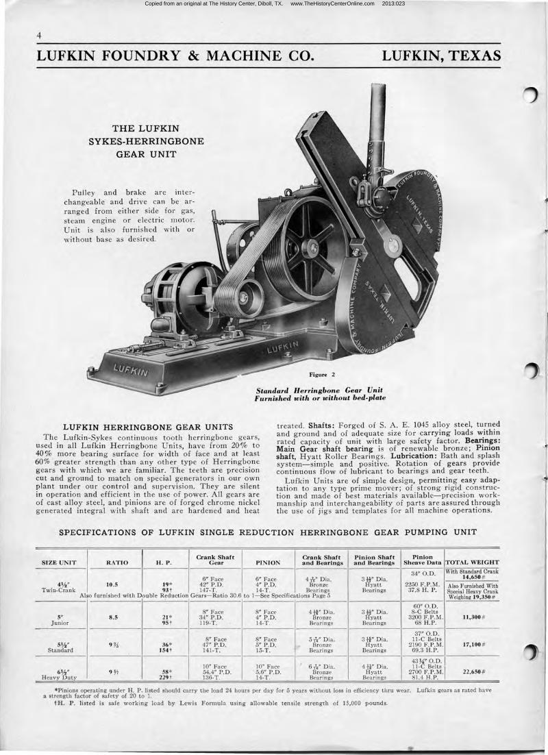
THE LUFKIN
SYKES-HERRINGBONE
GEAR UNIT
Pulley and brake are interchangeable and drive can be arranged from either side for gas, steam engine or electric motor. Unit is also furnished with or without base as desired.
Figure 2
Standard Herringbone Gear Unit Furnished with or without bed-plate
LUFKIN HERRINGBONE GEAR UNITS The Lufkin-Sykes continuous tooth herringbone gears,
used in all Lufkin Herringbone Units, have from 20% to 40 % more bearing surface for width of face and at least 60% greater strength t han any other type of Herringbone gears with which we are familiar. The teeth are precision cut and ground to match on special generators in our own plant under our control and supervision. They are silent in operation and efficient in the use of power. All gears are of cast alloy steel, and pinions are of forged chrome nickel generated integral with shaft and are hardened and heat
treated. Shafts: Forged of S. A. E. 1045 alloy steel, turned and ground and of adequate size for carrying loads within rated capacity of unit with large safety factor. Bea11n~s : Main Gear shaft bearing is of r enewable bronze; P1mon shaft, Hyatt Roller Beari ngs. Lubrication: Bath and splash system-simple and positive. Rotation of gears provide continuous flow of lubricant to bearings and gear teeth.
Lufkin Units are of simple design, permitting easy adaptation to any type prime mover; of strong rigid construction and made of best materials avai lable-precision workmanship and interchangeability of parts are assured through the use of jigs and templates for all machine operations.
SPE CIFICATIONS OF LUFKIN SINGLE REDUCTION HERRINGBONE GEAR PUMPING UNIT
Crank Shaft Crank Shaft Pinion Shaft Pin ion SI ZE UNIT R ATIO H .P. Gear PIN ION and Bearings and Bearinl?,s Sh ea ve Data TOTAL WEI GHT
34" O.D. With Standard Crank 6" Face 6" Face 4-ir;" D ia. 3H" Dia. 14,650 #
41/2" 10 .5 19* 42" P.D. 4" P.D. Bronze Hyatt 2250 F.P.M. Also Furnished With Twin-Crank 93t 147-T. 14-T. Bearings Bearings 37.8 H.P. Soecial Heavy Crank
Also furnished with Double R~duction Gears-Ratio 30.6 to 1-See Specifications Page 5 Weighing 19,350 #
60" O.D. 8" Face 8" Face 4tt" Dia . 3H" Dia. 8-C Belts
5" 8.5 21 * 34" P.D. 4" P .D . Bronze Hyatt 3200 F.P.M. 11,300 # Junior 95 t 119-T. 14-T. Bearings Bearings 6 H.P.
37" O.D . 8" Face 8" Face 5-ts" D ia . 3H" D ia. 11-C Belts
51h" 9 % 36* 47" P.D. 5" P.D. Bronze Hyatt 2190 F.P.M. 17,100 # Standard 154 t 141-T. 15-T.
'
' Bearings Bearings 69.3 H.P.
10" Face 10'' Face 6-ir;" Dia. 4fi" D ia. 43°74" O.D.1 11-C Belts
1 61h" 9 ~7 58 * 54.4" P.D. 5.6" P.D. Bronze Hyatt 2700 F.P.M. 22,650 #
Heavy Duty 229t 136-T. 14-T. Bearings Bearings 81.4 H.P.
*Pinions operating under H. P. listed should carry the load 24 hours per day for 5 years without loss in efficiency thru wear. Lufkin gears as rated have a strength factor of safety of 20 to 1.
1H. P. listed is safe working load by Lewis Formula using allowable tensile strength of 15,000 pounds.
t
Copied from an original at The History Center, Diboll, TX. www.TheHistoryCenterOnline.com 2013:023
I 1 3
5
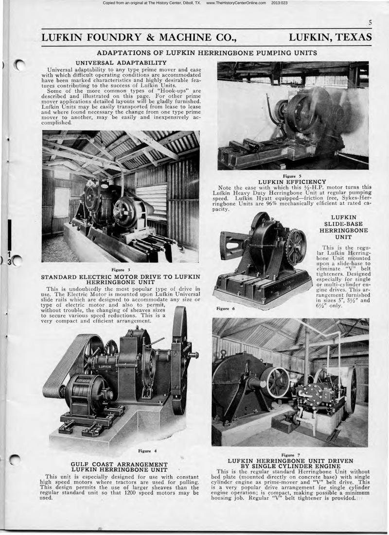
LUFKIN FOUNDRY & MACHINE CO., LUFKIN, TEXAS ADAPTATIONS OF LUFKIN HERRINGBONE PUMPING UNITS
UNIVERSAL ADAPTABIL I T Y Universal adaptability to any type prime mover and ease
with which difficult operating conditions are accommodated have been marked characteristics and highly desirable features contributing to the success of Lufkin Units.
Some of the more common types of "Hook-ups'' are described and illustrated on this page. For other prime mover applications detailed layouts will be gladly furnished. Lufkin Units may be easily transported from lease to lease and where found necessary the change from one type prime mover to another, may be easily and inexpensively accomplished.
Figure 3
S1TANDARD ELE CTRIC MOTOR DRIVE TO LUF KIN H E RRINGBONE UNIT
This is undoubtedly the most popular type of drive in use. The Electric Motor is mounted upon Lufkin Universal slide rails which are desi gned to accommodate any size or type of electric motor and also to permit, without trouble, the changing of sheaves sizes to secure various speed reductions. This is a very compact and efficient arran gement.
Figure 4
GULF COAST ARRANGEMENT L UFKIN HERRINGBONE UNIT
This unit is especially designed for use with constant high speed motors where tractors are used for pulling. This design permits the use of larger sheaves than the regular standard unit so that 1200 speed motors may be used.
Figure 5
LUFKIN EFFICIENCY Note the ease with which this 0 -H.P. motor turns this
Lufkin Heavy Duty Herringbone Unit at regular pumping speed. Lufkin Hyatt equipped-friction free, Sykes-Herringbone Units are 96% m echanically efficient at rated capacity.
Figure 7
LUFKIN SLIDE -BASE
HERRINGBONE UNIT
This is the regular Lufkin Herringbone Unit mounted upon a slide-base to eliminate "V" belt tighteners. Designed especially for single or multi-cylinder engine drives . This arrangement furnished in sizes 5", 50 " and 6W' only.
LUFKIN HERRINGBONE UNIT DRIVE N BY SINGLE CYLINDER ENGINE
This is the regular standard Herringbone Unit without bed plate (mounted directly on concrete base) with single cylinder engine as prime-mover and "V" belt drive. This is a very popular drive arrangement for single cylinder engine operation; is compact, making possible a minimum housing job. Regular "V" belt tightener is provided. :,
Copied from an original at The History Center, Diboll, TX. www.TheHistoryCenterOnline.com 2013:023
6
LUFKIN FOUNDRY & MACHINE CO. LUFKIN, TEXAS
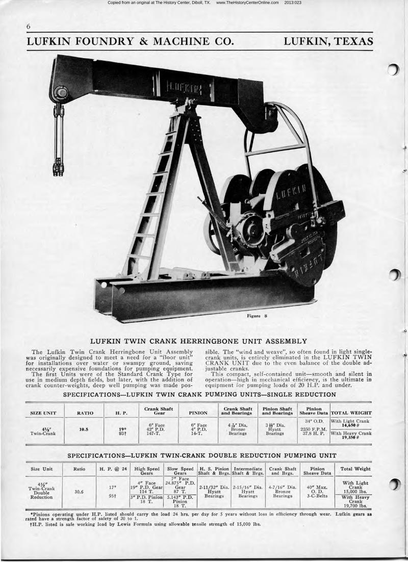
LUFKIN TWIN CRANK HERRINGBONE UNIT ASSEMBLY
The Lufkin Twin Crank Herringbone Unit Assembly was originally designed to meet a need for a "floor unit" for installations over water or swampy ground, saving necessarily expensive foundations for pumping equipment.
The first Units were of the Standard Crank Type for use in medium depth fields, but later, with the addition of crank counter-weights, deep well pumping was made pos-
sible. The "wind and weave", so often found in· light singlecrank units, is entirely eliminated in the LUFKIN TWIN CRANK UNIT due to the even balance of the double adjustable cranks.
This compact, self-contained unit-smooth and silent in operation-high in mechanical efficiency, is the ultimate in equipment .for pumping loads of 20 H.P. and under.
SPECIF ICATIONS-LUFKIN TWIN CRANK PUMPING UNITS-SINGLE REDUCTION
Crank Shaft Crank Shaft Pinion Shaft Pinion ~IZE UNIT R ATIO H . P . G ear PINION and Bearings and Bearings Sheave Data TOTAL WEIGHT
34" 0.D. With Light Crank 6" Face 6" Face 4h" D ia. 3H'' Dia. 14,650 #
4%" 10.5 19* 42" P.D . 4" P.D . Bronze Hyatt 2250 F .P.M. Twin-Crank 93t 147-T. 14-T. Bearings Bearings 37.8 H.P. With Heavy Crank
19,350 #
SPECIFICATIONS-LUFKIN TWIN-CRANK DOUBLE REDUCTION PUMPING UNIT
Size Unit Ratio H . P.@ 24 High Speed Slow Speed H . S. Pinion Intermediate Crank Shaft Pinion Total W eight Gears Gears Shaft & Brgs. Shaft & Brgs. and Brgs. Sheave D ata
7" Face 4~" 4" Face 24.875" P.D. With Light
Twin-Crank 17* 19" P.D. Gear Gear 2-11/32" Dia. 2-15/16" Dia. 4-7 /16" Dia. 40" Max. Crank Double 30.6 114 T. 87 T. Hyatt Hyatt Bronze O.D. 15,000 lbs.
Reduction 9St 3" P.D. Pinion 5.143" P .D. Bearings Bearings Bearings 3-C-Belts With Heavy 18 T. Pinion Crank
18 T. 19,700 lbs.
•Pinions operating under H .P. listed should carry the load 24 hrs. per day for 5 years without loss in efficiency through wear. Lufkin gears as rated have a strength factor of safety of 20 to 1.
tH.P. listed is safe working load by Lewis Formula using allowable tensile strength of 15,000 lbs.
Copied from an original at The History Center, Diboll, TX. www.TheHistoryCenterOnline.com 2013:023
7
LUFKIN FOUNDRY & MACHINE CO. LUFKIN, TEXAS
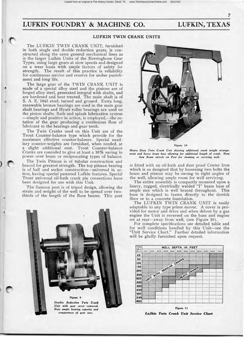
L UFKIN TWIN CRANK UNITS
The LUFKIN TWIN CRANK UNIT, furnished in both single and double reduction gears, is constructed along the same general mechanical lines as is the larger Lufkin Units of the Herringbone Gear Types, using large gears at slow speeds and designed on a wear basis with ample factors of safety for strength. The result of this practice is reliability for continuous service and reserve for undue punishment and long life.
The large gear of the TWIN CRANK UNIT is made of a special alloy steel and the pinions are of forged alloy steel, generated integral with shafts, and are hardened and heat treated. The main shaft is of S. A. E. 1045 steel, turned and ground. Extra long, renewable bronze bearings are used in the main gear shaft bearings and Hyatt roller bearings are used on the pinion shafts. Bath and splash lubrication system -simple and positive in action, is employed,- the rotation of the gear producing a continuous flow of lubricant to the bearings and gear· teeth.
The Twin Cranks used on this Unit are of the Trout Counter-balance type which provide for the maximum effective counter-balance. Special auxiliary counter-weights are furnished, when needed, at a slight additional cost. Trout Counter-balance Crank are conceded to give at least a 10% saving in power over beam or reciprocating types of balance.
The Twin Pitman is of tubular construction and braced for greatest strength. The top pitman bearing is of ball and socket construction-universal in action, having pecial patented Lufkin features. Special Trout universal oil-bath crank pin connections have been designed for use with this Unit.
The Samson post is of tripod design, allowing the strain and weight of the well to be spread over twothirds of the length of the Base beams. This post
Figure 9
Double Reduction Twin Cranlr Unit with gear coYer , remoYed. Note ample bearing capacity and
compactness of gear case.
Figure 10
H eayy Duty Twin Crank Unit showing additional crank weight arrange• ment and heaYy beam base allowing for additional length of crank. Note
how Beam swiYels on Post for cleaning or serYicing well.
is fitted with an oil-bath and dust proof Center Iron which is so designed that by loosening two bolts the beam and pitman may be swung to right angles of the well, allowing ample room for well servicing.
The entire assembly is compactly mounted upon a heavy, rugged, electrically welded "I" beam base of ample size which is well braced throughout. This base is designed to fasten directly to the derrick floor or to a concrete foundation.
The LUFKIN TWIN CRANK UNIT is easily adaptable to any type prime mover. A cover is provided for motor and drive and when driven by a gas engine the Unit is reversed on the base and engine set at rear- away from well, (see Figure 10).
For complete specifications see detailed table and for well conditions handled by this Unit- see the "Unit Service Chart." Further detailed information will be gladly furnished upon request.
Figure 11
Lu/kin Twin Crank Unit Service Chari
Copied from an original at The History Center, Diboll, TX. www.TheHistoryCenterOnline.com 2013:023
LUFKIN FOUNDRY & MACHINE CO.
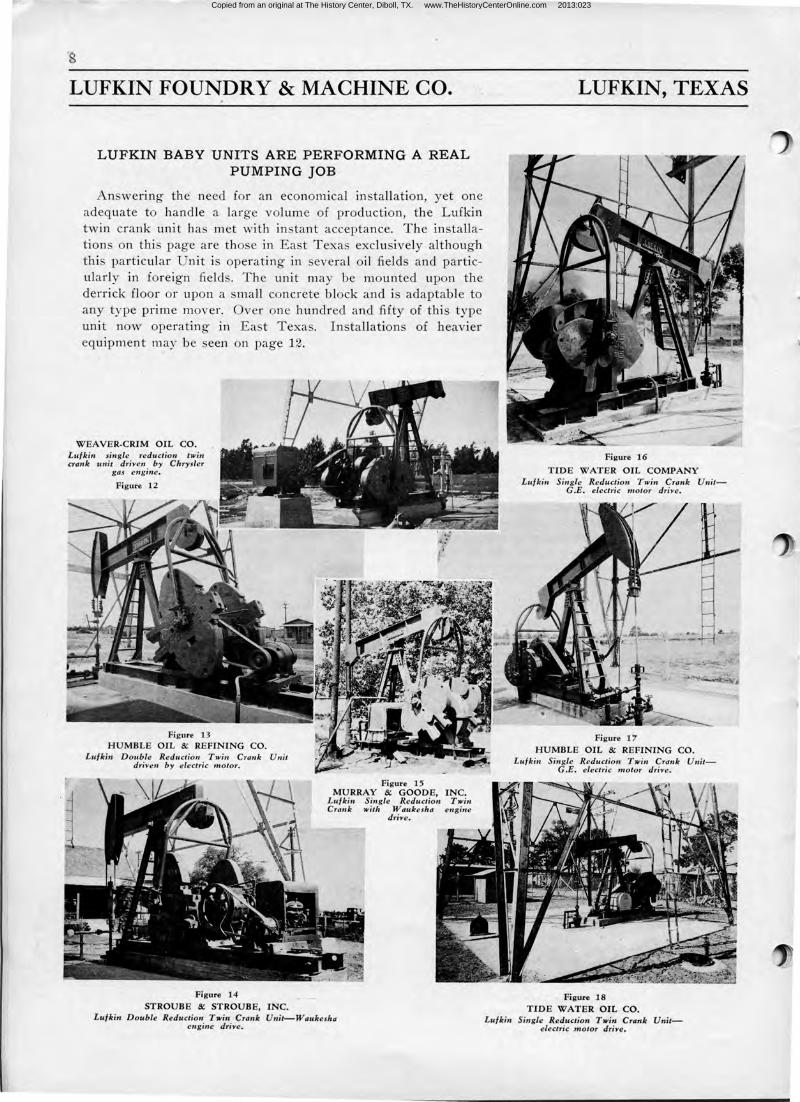
LUFKIN BABY UNITS ARE PERFORMING A REAL PUMPING JOB
An wering the need for an economical in tallation, yet one adequate to handle a large volume of production, the Lufkin twin crank unit has met with instant acceptance. The installations on this page are those in East Texas exclusively although this particular Unit i operating in everal oil field and particularly in foreign fields. The unit may be mounted upon the derrick floor or upon a small concrete block and i adaptable to any type prime mover. Over one hundred and fifty of this type unit now operating in East Texas. Installations of heavier equipment may be seen on page 12.
WEAVER-CRIM OIL CO. Lufkin single reduction twin crank unit dri-ven by Chrysler
gas engine.
12
Figure 13 HUMBLE OIL & REFINING CO.
Lufkin Double Reduction Twin Crank Unit dri-ven by electric motor.
Figure 14
STROUBE & STROUBE, INC.
Figure 15 MURRAY & GOODE, INC.
Lufkin Single Reduction Twin Crank with Waukesha engine
dri-ve.
Lufkin Double Reduction Twin Crank Unit-Waukesha engine dri-ve.
LUFKIN, TEXAS
Figure 17 HUMBLE OIL & REFINING CO.
Lufkin Single Reduction Twin Crank UnitG.E. electric motor dri-ve.
Figure 18
TIDE WATER OIL CO. Lufkin Single Reduction Twin' Crank Unit
electric motor dri-ve.
Copied from an original at The History Center, Diboll, TX. www.TheHistoryCenterOnline.com 2013:023
9
LUFKIN FOUNDRY & MACHINE CO. LUFKIN, TEXAS
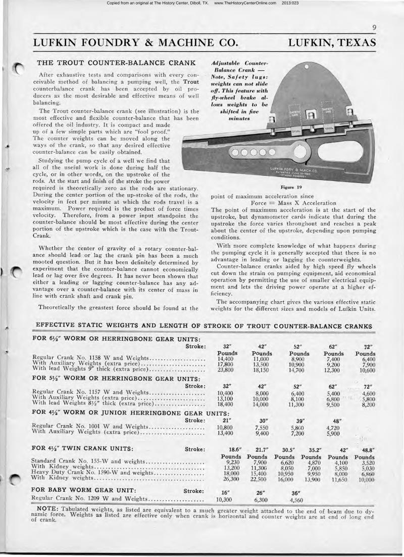
THE TROUT COUNTER-BALANCE CRANK
fter exhaustive test and compari ons with every conceivable method of balancing a pumping well, the Trout counterbalance crank ha been accepted by oil producers as the most desirable and effective means of well balancing.
The Trout counter-balance crank (see illustration) is the most effective and flexible counter-balance that has been offered the oil industry. It is compact and made up of a few simple part which are "fool proof." The counter weight can be moved along the ways of the crank, o that any desired effective counter-balance can be easily obtained.
Studying the pump cycle of a well we find that all of the useful work is _done during half the cycle, or in other words, on the upstroke of the rods. At the start and finish of the stroke the power required· is theoretically zero as the rods are stationary. During the center portion of the up-stroke of the rods, the ve locity _in feet per minute at which the rods travel is a maximum. Power required is the product of force times ve locity. Therefore, from a power input standpoint the counter-balance should be most effective during the center portion of the upstroke which is the case with the TroutCrank.
Whether the cei1ter of gravity of a rotary counter-balance should lead .or · lag the crank pin has been a much mooted question. · But · it has been definitely determined by experiment that the counter-balance cannot economically lead or lag over five degrees. It has never been shown that either a leading or lagging counter-balance has any advantage over a counter-balance with its center of mass in line with crank shaft and crank pin.
Theoretically the greastest force should be found at the
Adjustable Counter-Balance Crank -
Note, Sa/ ety lugs: weights can not slide off. This feature with fly-wheel brake allows weights to be
shifted in five 1ninutes
Figure 19
point of maximum acceleration since Force = Mass X Acceleration
The point of maximum acceleration is at the start of the upstroke, but dynamometer cards indicate that during the upstroke the force varies throughout and reaches a peak about the center of the upstroke, depending upon pumping conditions.
With more complete knowledge of what happens during the pumping cycle it is generally accepted that there is no advantage in leading or lagging the counterweights.
Counter-balance cranks aided by high speed fly wheels cut down the strain on pumping equipment, aid economical operation by permitting the use of smaller electrical equipment and lets the driving power operate at a higher efficiency.
The accompanying chart gives the va rious effective static weights for the different sizes and models of Lufkin Units.
EFFECTIVE STATIC WEIGHTS AND LENGTH OF STROKE OF TROUT COUNTER-BALANCE CRANK1S
F OR 6Yz" WORM OR HERRINGBONE GEAR UNITS: Stroke:
Regular Crank No. 1158 W and Weights . ....... ......... .. . With Auxiliary Weights (extra price) ...................... . With lead Weights 9" thick (extra price) ...... .. ........... .
FOR 5Yz'' WORM OR HERRINGBONE GEAR UNITS:
32" Pounds 14,400 17,800 23,800
Stroke: 32" Regular Crank No. 1157 W and Weights.................... 10,400 With Auxiliary Weights (extra price)........................ 13,100 With lead Weights 8:0" thick (extra price).................. 18,400
FOR 4Yz'' WORM OR JUNIOR HERRINGBONE GEAR UNITS : Stroke :
Regular Crank No. 1001 W and Weights ................... . With Auxiliary Weights (extra price) ...................... .
FOR 4Yz" TWIN CRANK UNITS: Stroke:
Standard Crank No. 155-W and weights .................... . With Kidney weights ...................................... . Heavy Duty Crank No. 1590-W and weights ................. . With Kidney weights ................. _ .............. . ...... .
F OR BABY WORM GEAR UNIT: Stroke: Regular Crank No. 1209 W and Weights ................... .
21" 10,800 13,400
18.6" Pounds
9,230 13,200 18,000 26,300
16" 10,300
42" Pounds 11,000 13,500 18,150
42" 8,000
10,000 14,000
30" 7,550 9,400
21.7" Pounds
7,900 11,300 15,400 22,500
26" 6,300
52" 62" ']2" Pounds Pounds Pounds 8,900 7,400 6,400
10,900 9,200 7,900 14,700 12,300 ~0,600
52" 62" .. , 72" 6,400 5,400
i: 'I' 4,600
8,100 6,800 -'. 5,800 11,300 9,500 8,200
39" 48" 5,800 4,720 7,200 5,900
.,: jl,
30.5" 35.2" 42" "48.8" Pounds Pounds Pounds Pouhds
6,620 4,870 4,100 3,520 8,050 -7,000 5,850 5,030
10,950 9,950 8,000 6,860 16,000 13,900 11,650 10,000
36" 4,560
NOTE: Tabulated weights, as listed are equivalent to a much greater weight attached to the end of beam due to dynamic force. Weights as listed are effective only when crank is horizontal and counter weights are at end of long end of crank.
Copied from an original at The History Center, Diboll, TX. www.TheHistoryCenterOnline.com 2013:023
10
LUFKIN FOUNDRY & MACHINE CO. LUFKIN, TEXAS
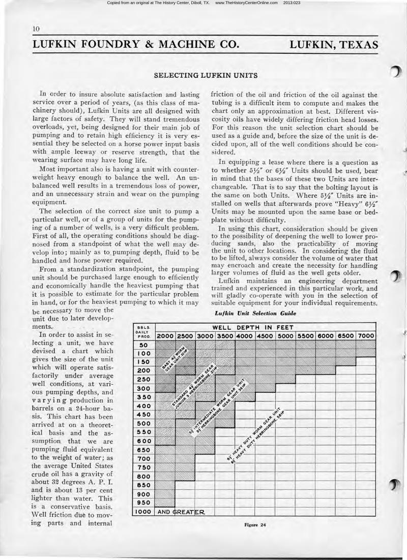
SELECTING LUFKIN UNITS
In order to insure absolute satisfaction and lasting service over a period of years, (as this class of machinery should), Lufkin Units are all designed with large factors of safety. They will stand tremendous overloads, yet, being designed for their main job of pumping and to retain high efficiency it is very essential they be selected on a horse power input ·basis with ample leeway or reserve strength, that the wearing surface may have long life.
Most important also is having a unit with counterweight heavy enough to balance the well. An unbalanced well results in a tremendous loss of power, and an unnecessary strain and wear on the pumping equipment.
The selection of the correct size unit to pump a particular well, or of a group of units for the pumping of a number of wells, is a very difficult problem. First of all, the operating conditions should be diagnosed from a standpoint of what the well may develop into; mainly as to . pumping depth, fluid to be handled and horse power required.
From a standardization standpoint, the pumping unit should be purchased large enough to efficiently and economically handle the heaviest pumping that it is possible to estimate for the particular problem in hand, or for the heaviest pumping to which it may be neces~ary to move the unit due to later develop-men ts.,
In order to assist in selecting a unit, we have devised a chart which gives the size of the unit which will operate satis,.. factorily under average well conditions, at various pumping depths, and varying production in barrels on a 24-hour basis. This chart has been arrived at on a theoretical basis and the assumption that we are pumping fluid equivalent to the weight of water; as the average United States crude oil has a gravity of about 32 degrees A. P. I. and is about 13 per cent lighter than water. This 1s a conservative b_asis. Well friction due to moving parts and internal
BB LS. DAILY
PROD.
50 100 I 50 200 250
300 350 400 450
550
600 6,50 .
700 750
800 850
900 950
1000
friction of the oil and friction of the oil against the tubing is a difficult item to compute and makes the chart only an approximation at best. Different viscosity oils have widely differing friction head losses. For this reason the unit selection chart should be used as a guide and, before the size of the unit .is decided upon, all of the well conditions should be considered.
In equipping a lease where there is a question as to whether 5~" or 6~" Units should be used, bear in mind that the bases of these two Units are interchangeable. That is to say that the bolting layout is the same on both Units. Where 5~" Units are in-. stalled on wells that afterwards prove "Heavy" 6~" Units may be mounted upon the same base or bedplate without difficulty.
In using this chart, consid~ration should be given to the possibility of deepening the well to lower producing sands, . also the practicability of moving the unit to other locations. In considering the fluid to be lifted, always consider the volume of water that may encroach and create the necessity for handling larger volumes of fluid as the well gets older.
Lufkin maintains an engineering department trained and experienced in this particular work, and will gladly co-operate with you in the selection of suitable equipment for your individual requirements.
Lu/kin Unit Selection Guide
Figure 24
Copied from an original at The History Center, Diboll, TX. www.TheHistoryCenterOnline.com 2013:023
11
LUFKIN FOUNDRY & MACHINE CO. LUFKIN, TEXAS
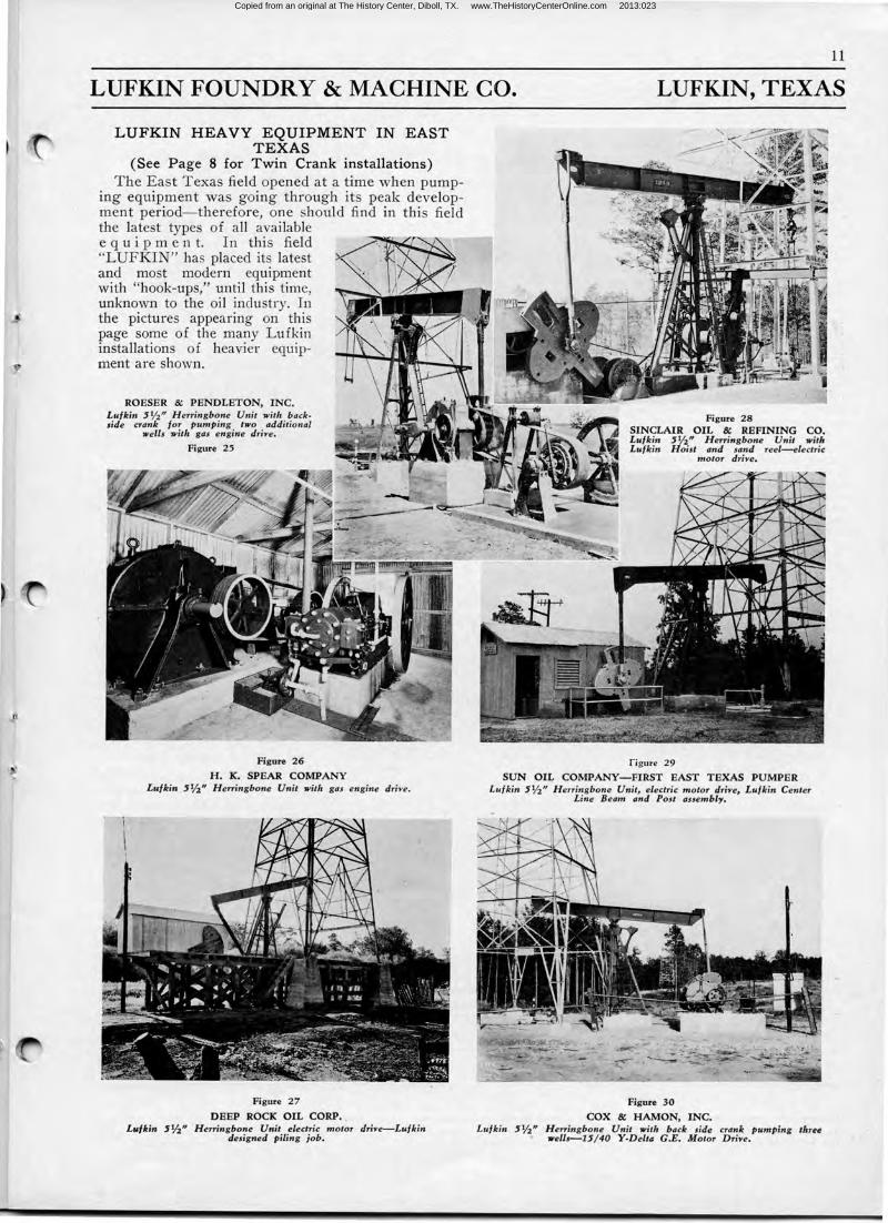
LUFKIN HEAVY EQUIPMENT IN EAST TEXAS
(See Page 8 for Twin Crank installations) The East Texas field opened at a time when pump
ing equipment was going through its peak development period- therefore, one should find in this field the latest types of all available e q u i p m e n t. In this field "LUFKIN" has placed its latest and most modern equipment with "hook-ups," until this time, unknown to the oil industry. In the pictures appearing on this page some of the many Lufkin installations of heavier equipment are shown.
ROESER & PENDLETON, INC. Lufkin 5¥2" Herringbone Unit with backside crank for pumping two additional
wells with gas engine driYe.
Figure 25
Figure 26
H. K. SPEAR COMPANY Lufkin 5%" Herringbone Unit with gas engine driYe.
Figure 27
DEEP ROCK OIL CORP. , Lufkin 5%" Herringbone Unit electric motor driYe-Lufkin
designed piling job.
rigure 29
SUN OIL COMPANY-FIRST EAST TEXAS PUMPER Lufkin 5¥2" Herringbone Unit, electric motor driYe, Lufkin Center
Line Beam and Post assembly.
Figure 30
COX & HAMON, INC. Lufkin 5¥2" Herringbone Unit with back side crank pumping three
wells-15/ 40 ¥-Delta G.E. Motor DriYe.
Copied from an original at The History Center, Diboll, TX. www.TheHistoryCenterOnline.com 2013:023
12
LUFKIN FOUNDRY & MACHINE CO.
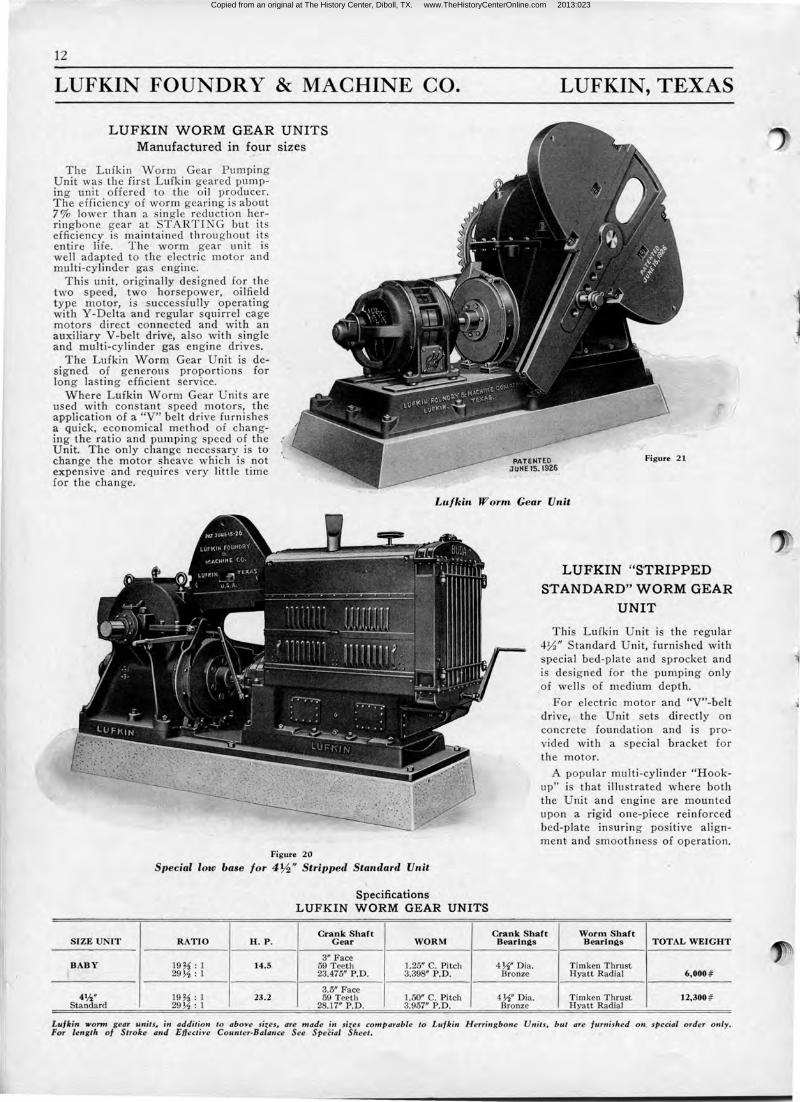
L UF KIN WORM GEAR UNIT S Manufactured in four sizes
The Lufkin Worm Gear Pumping Unit was the first Lufkin geared pumping unit offered to the oil producer. The efficiency of worm gearing is about 7 % lower than a single reduction herringbone gear at STARTING but its efficiency is maintained throughout its entire life. The worm gear unit is well adapted to the electric motor and multi-cylinder gas engine.
This unit, originally designed for the two speed, two horsepower, oilfield type motor, is successfully operating with Y-Delta and regular squirrel cage motors direct connected and with an auxiliary V-belt drive, also with single and multi-cylinder gas engine drives.
The Lufkin Worm Gear Unit is designed of generous proportions for long lasting efficient servic.e.
Where Lufkin Worm Gear Units are used with constant speed motors, the application of a "V" belt drive furnishes a quick, economical method of changing the ratio and pumping speed of the Unit. The only change necessary is to change the motor sheave which is not expensive and requires very little time for the change.
LUFKIN, TEXAS
Figure 2 1
Lu/ kin W orm Gear Unit
Figure 20
S pecial low base fo r 4%" Stripped Standard Unit
Specifications LUF KIN WORM GEAR UNITS
Crank Shaft SI ZE UNIT R ATIO H . P. Gear WORM
3" Face BAB Y 19%: 1 14.5 59 Teeth 1.25" C. Pitch
29Y2 : 1 23.475" P.D. 3.398" P.D.
3.5" Face 4%" 19%: 1 23.2 59 Teeth 1.50" C. Pitch
Standard 29 Y2 : 1 28.17" P.D. 3.957" P.D.
LUFKIN "STRIPPED STANDARD" WORM GEAR
UNIT
This Lufkin Unit is the regular 4~" Standard Unit, furnished with special bed-plate and sprocket and is designed for the pumping only
.-of . wells of medium depth.
For electric motor and "V"-belt drive, the Unit . sets directly on concrete foundation and is provided with a special bracket for the motor.
A popular multi-cylinder "Hookup" is that illustrated where both the Unit and engine are mounted upon a rigid one-piece reinforced bed-plate insuring positive alignment and smoothness of operation.
Crank Shaft Worm Shaft Bearin~s Bearin~s TOTAL WEIGHT
4Y2" Dia. Timken Thrust Bronze Hyatt Radial 6,000 #
4Y2" Dia. Timken Thrust 12,300 # Bronze Hyatt Radial
Lu/kin wonn gear units. in addition to aboYe sizes. are made in sizes comp arable to Lufkin Herringbone Units, but are furnis hed on_ special order only. For length of S troke and Eflecti'>'e Counter-B'alance See Special Sheet.
1 J
Copied from an original at The History Center, Diboll, TX. www.TheHistoryCenterOnline.com 2013:023
1:3
LUFKIN FOUNDRY & MACHINE CO. LUFKIN, TEXAS
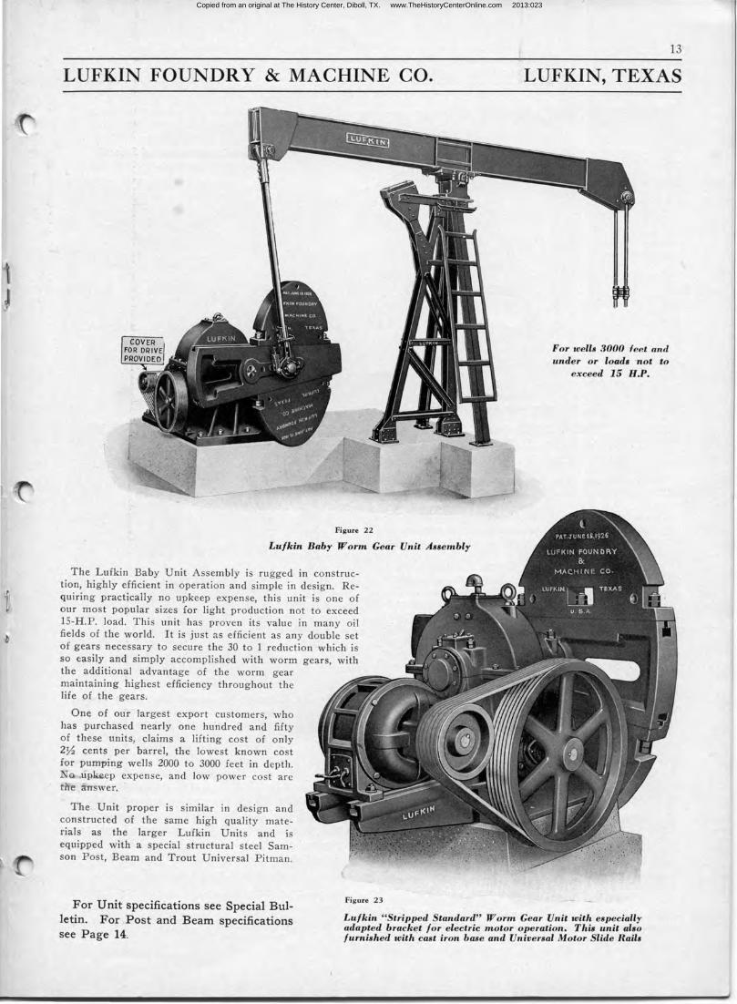
Figure 22
Lu/kin Baby Worm Gear Unit ABBembly
The Lufkin Baby Unit Assembly is rugged in construction, highly efficient in operation and simple in design. Requiring practically no upkeep expense, this unit is one of our most popular sizes for light production not to exceed 15-H.P. load. This unit has proven its value in many oil fields of the world. It is just as efficient as any double set of gears necessary to secure the 30 to 1 reduction which is so easily and simply accomplished with worm gears, with the additional advantage of the worm gear maintaining highest efficiency throughout the life of the gears.
One of our largest export customers, who has purchased nearly one hundred and fifty of these units, claims a lifting cost of only 27'2 cents per barrel, the lowest known cost for pumping wells 2000 to 3000 feet in depth. No up~ep expense, and low · power cost are t.ne answer.
The Unit proper is similar in design and constructed of the same high quality materials as the larger Lufkin Units and is equipped with a special structural steel Samson Post, Beam and Trout Universal Pitman.
Figure 23
For well8 3000 feet an.rl under or loads not to
exceed 15 H.P.
For Unit specifications see Special Bulletin. For Post and Beam specifications see Page 14.
Lufkin " Stripped Standard" Worm Gear Unit with e8pecially adapted bracket for electric motor operation. This unit a'8o furnished with cast iron base and Universal Motor Slide Rail•
Copied from an original at The History Center, Diboll, TX. www.TheHistoryCenterOnline.com 2013:023
14
LUFKIN FOUNDRY & MACHINE CO. LUFKIN, TEXAS
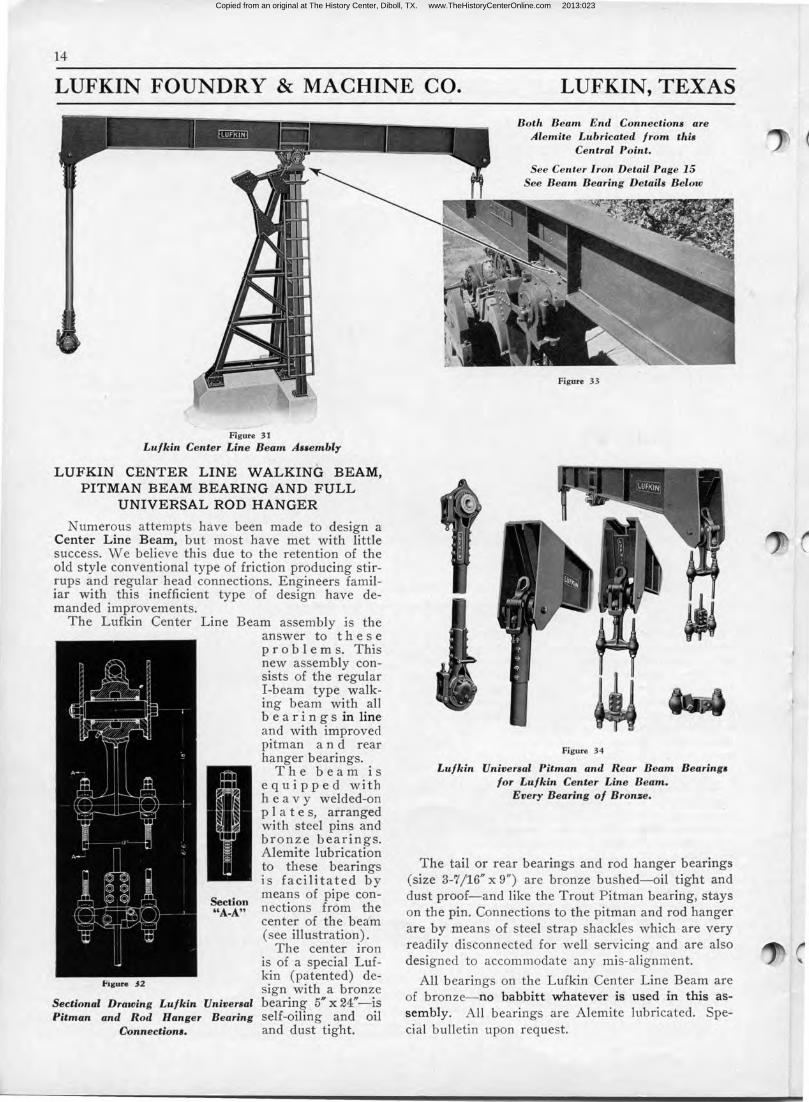
-Figure 31
Lufkin Center Line Beam AHembly
LUFKIN CENTER LINE WALKING BEAM, PITMAN BEAM BEARING AND FULL
UNIVERSAL ROD HANGER
Numerous attempts have been made to design a Center Line Beam, but most have met with little success. We believe this due to the retention of the old style conventional type of friction producing stirrups and regular head connections. Engineers famil iar with this inefficient type of design have demanded improvements.
The Lufkin Center Line Beam assembly is the answer to t h e s e p r o b 1 e m s. This new assembly consists of the regular I-beam type walking beam with all b e a r i n g s in line and with improved pitman and rear hanger bearings.
Figure J 2
The beam is equipped with h e a v y welded-on p 1 a t e s, arranged with steel pins and bronze bearings. Alemite lubrication to these bearings is facilitated by means of pipe con
~A~!\,!1 nections from the center of the beam (see illustration).
The center iron is of a special Lufkin (patented) design with a bronze
Sectional Drawing Lufkin Universal bearing , 5" x 24"-is Pitman and Rod Hanger Bearing self-oiling and oil
Oonnection1. and dust tight.
Both Beam End Connections are Alemite Lubricated from thi1
Central Point.
See Center Iron Detail Page 15 See Beam Bearing Details Below
Figure 33
Figure 34
Lufkin Universal Pitman and Rear Beam Bearing• for Lu/kin Center Line Beam.
Every B earing of Bron:re.
The tail or rear bearings and rod hanger bearings (size 3-7/16" x 9") are bronze bushed-oil tight and dust proof-and like the Trout Pitman bearing, stays on the pin. Connections to the pitman and rod hanger are by means of steel strap shackles which are very readily disconnected for well servicing and are also designed to accommodate any mis-alignment.
All bearings on the Lufkin Center Line Beam are of bronze- no babbitt whatever is used fn this assembly. All bearings are Alemite lubricated. Special bulletin upon request.
Copied from an original at The History Center, Diboll, TX. www.TheHistoryCenterOnline.com 2013:023
15
LUFKIN FOUNDRY & MACHINE CO. LUFKIN, TEXAS
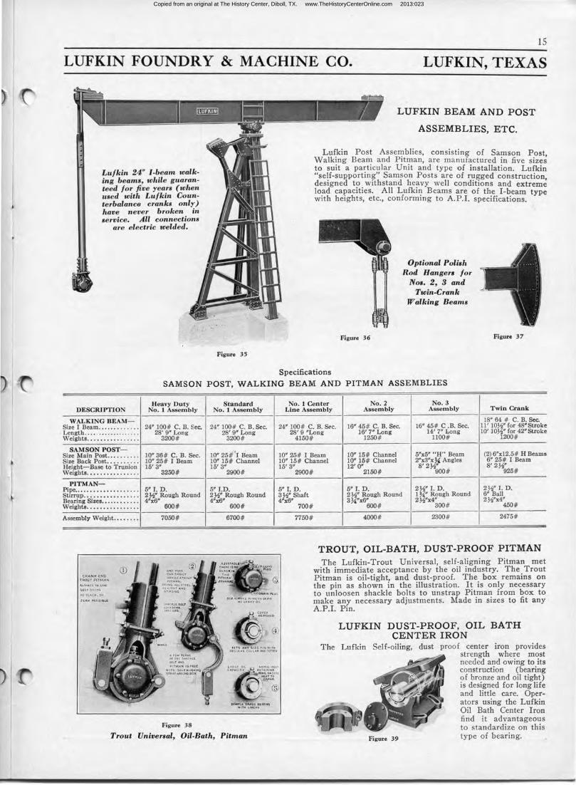
Lufkin 24" I-beam walking beams, while guaranteed for five years (when used with Lufkin Counterbalance cranks only) have never broken in service. All connections
are electric welded.
.. " ~
Figure 35
LUFKIN BEAM AND POST
ASSEMBLIES, ETC.
Lufkin Post Assemblies, consisting of Samson Post Walking Beam and Pitman, are manufactured in five size~ to suit a particular Unit and type of installation. Lufkin "self-suP.porting" Samson Posts are of rugged construction designed to withstand heavy well conditions and extrem~ load capacities. All Lufkin Beams are of the I-beam type with heights, etc., conforming to A.P.I. specifications.
Figure 36
Specifications
Optional Polish Rod Hangers for
Nos. 2, 3 and Twin-Crank
Walking Beams
Figure 37
SAMSON POST, WALKING BEAM AND PITMAN ASSEMBLIES
Heavy Duty Standard DESCRIPTION No. 1 Assembly No. 1 Assembly
WALKING BEAM-Size I Beam ..•..•....... 24" 100# C. B. Sec. 24" 100# C. B. Sec. Length ...• . ........ ... .. . 28' 9" Long 28' 9" Long Weights ....•••••....... 3200# 3200#
SAMSON POST- i( Size Main Post .••....... 10" 36# C. B. Sec. 10" 25# I Beam Size Back Post .•........ 10" 25# I Beam 10" 15# Channel Height-Base to Trunion 15' 3" 15' 3" Weights .••.••.•.•.•.... 3250# 2900#
PITMAN-Pipe ..••.•••••••••••.... 5" I. D. 5" I.D. Stirrup .•••••••••••..... 2 Y2" Rough Round 2 Y2" Rough Round Bearing Sizes ............ 4"x6" 4"x6" Weights .••••..•.••..... 600# 600#
Assembly Weight .••...•• 7050# 6700#
Figure 38
Trout Universal, Oil-Bath, Pitman
No. 1 Center No. 2 No. 3 T win Crank Line Assembly Assembly Assembly
18" 64 # C. B. Sec. 24" 100# C. B. Sec. 16" 45# C. B. Sec. 16" 45# C .B. Sec. 11' lOYz" for 48"Stroke
14' 7" Long 10' lOYz" for 42" Stroke 28' 9 "Long 16' 7" Long 1250# 1100# 1200# 4150#
10" 25# I Beam 10" 15# Channel 5"x5" "H" Beam (2) 6"x12.5# H Beams 2"x3"x ~ Angles 6" 25# I Beam 10" 15# Channel 10" 15# Channel
8' 2Yz" 15' 3" 2900#
5" I. D. 3Y2" Shaft 4"x6"
700#
7750#
12' O" 8' 2Y2" 2150# 900# 925#
5" I. D. 2Yz" I. D. 2Yz" I. D. 2 Y2" Rough Round 1 '4" Rough Round 6" Ball
3~"x6~00# 2Yz"x4" 2Y2"x4" 300# 450#
4000# 2300# 2475#
TROUT, OIL-BATH, DUST-PROOF PITMAN The Lufkin-Trout Universal, self-aligning Pitman met
with immediate acceptance by the oil industry. The Trout Pitman is oil-tight, and dust-proof. The box remains on the pin as shown in the illustration. It is only necessary to unloosen shackle bolts to unstrap Pitman from box to make any necessary adjustments. Made in sizes to fit any A.P.I. Pin.
LUFKIN DUST-PROOF, OIL BATH CENTER IRON
The Lufkin Self-oiling, dust proof center iron provides strength where most needed and owing to its construction (bearing of bronze and oil tight) is designed for long life and little care. Operators using the Lufkin Oil Bath Center Iron find it advantageous to standardize on this
Figure 39 type of bearing.
Copied from an original at The History Center, Diboll, TX. www.TheHistoryCenterOnline.com 2013:023
16
LUFKIN FOUNDRY & MACHINE CO. LUFKIN, TEXAS
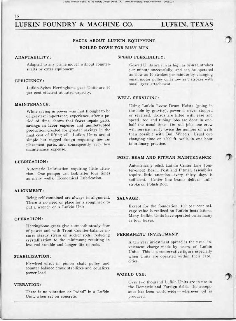
FACTS ABOUT LUFKIN EQUIPMENT
BOILED DOWN FOR BUSY ME N
ADAPTABILITY :
Adapted to any prime mover without countershafts or extra equipment.
E F F ICIENCY :
Lufkin-Sykes Herringbone gear Units are 96 per cent efficient at rated capacity.
MAINTENANCE :
While saving in power was first thought to be of greatest importance, experience, after a period of time, shows that fewer repair parts, savings in labor expense and uninterrupted production created for greater savings in the final cost of lifting oil. Lufkin Units are of simple but rugged design requiring few replacement parts, and consequently very low maintenance expense.
LUBRICATION :
Automatic Lubrication requiring little attention. One pumper can look after four times as many wells. Economical Lubrication.
AL IGNMENT :
Being self-contained are always in alignment. There is no need or place for a roughneck to put a wrench on a Lufkin Unit.
OPE RATION :
Herringbone gears give a smooth steady flow of power and with Trout Counter-balance · insures steady strain on sucker rods; reducing crystallization to the minimum; resulting m less rod trouble and longer life to rods.
STABILIZATION :
Flywheel effect in p1mon shaft pulley and counter balance crank stabilizes and equalizes power load.
VIBRATION :
There is no vibration or "wind" m a Lufkin Unit, when set on concrete.
SPEED FLEXIBILITY :
Geared Units are run as high as 37-6 ft. strokes per minute successfully, and can be · operated as slow as 10 strokes per minute by changing small motor pulley or as low as 3 strokes with small gear attachment.
WELL SERVICING :
Using Lufkin Loose Drum Hoists (going in the hole by gravity), power is never stopped or reversed. Loads are lifted with ease and speed; rod and tubing jobs are done in onehalf the usual t ime. On rod jobs one crew will service nearly twice the number of wells than possible with Bull Wheels. Usual cup changing time on 4000 ft. wells in one hour is ordinary practice.
POST, BEAM AND PITMAN MAINTENANCE :
Automatically oiled, Lufkin Center Line ( center-oiled) Beam, Post and Pitman assemblies require little attention-every thirty days is sufficient. Center line beams deliver "full" stroke on Polish Rod.
SALVAGE :
Except for the foundation, 100 per cent salvage value is realized on Lufkin installations. Many Lufkin Units have operated on as many as four leases.
PERMANENT INVESTMENT :
A ten year investment spread is the usual investment charge made by users of Lufkin Units. This is a conservative figure especially when Units are operated within their capacities.
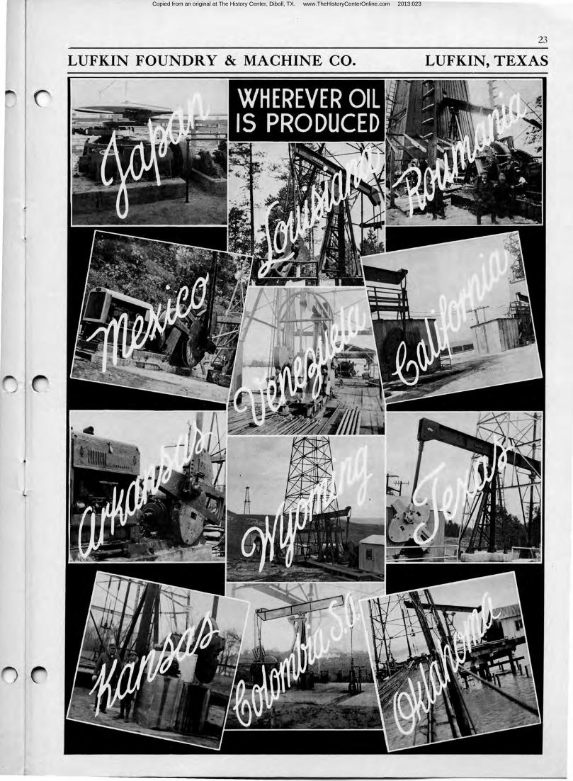
WORLD USE :
Over two thousand Lufkin Units are in use in the Domestic and Foreign fields. Its acceptance has been world-wide - wherever oil is produced.
Copied from an original at The History Center, Diboll, TX. www.TheHistoryCenterOnline.com 2013:023
I 1
17
LUFKIN FOUNDRY & MACHINE CO. LUFKIN, TEXAS
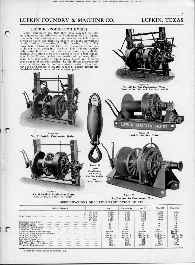
LUFKIN PRODUCTION HOISTS Lufkin Engineers feel that they have reached the ult i
mate in operating efficiency in Production Hoists. Operation under the most severe conditions in the fie ld over a period of years, has definitely proven the many advantages of t he Lufkin "Loose-drum" roller bearing Hoists. T he loose drum feature permits the Hoist to r everse without use of Power when going into the hole. This is fou nd particularly des irable when using multi-cylinder or sing le cylinder engines. All Lufkin Hoists are equipp ed with Trout Expansion Brake . Drums, which are unaffected by heat; Hyatt drum bearings; asbestos clutch brake blocks and asbest·os brake bands ·of superior quality. Lufkin Hoists are ruggedly constructed and are fast and powerful in action. Time pulling rods and tubing is greatly reduced. Lufkin Hoists are furnished with either steel or wooden posts.
Figure 40
No. 2 Lufkin Production Hoist
Figure 41
Lufkin Combination Ball Bearing
Rod Line Weight and
"Sister Hooks"
Figure 43 No. 52 Lufkin Production Hoist
(Same as No. 522 with line shaft added)
Figure 44 Lufkin Simplex
Figure 45 No. 6 Lufkin Production Hoist ( Same as No. 2 without line shaft)
'Lufkin No. 16 Production
SPECIFICATIONS OF LUFKIN PRODUCTION HOISTS
DIMENSIONS
, %"Line l -(,;''Line
Line Capacity .. . . . . . . . . . . . . . . . . . . . . . . . . . . . . . . . . . . . . . . . . . U" Line Ys" Line 1" Line
Dia meter Drum Shaft. ................................................... . D jam eter D rum ............................... . .. . .......... .. .. ....... . . Length of Drum ..... ...................... .. ......... ... .....•. ..... . .... D iameter Drum Flanges .... . .............. ........... . . .. ........ ........ . Diameter Line Shaft .•... ................... : ............................ . Line and Drum Shaft Bearings ..... .. ..... . ............................... . Drum .or Clutch Sprocket Bearings* .. .. . ................................... . Area Br~king Surface ... ........ . . ................................. .. ...... . Area Friction Clutch ..... ......... . .................... . ......... ........ . Low Speed Sprocket. ..... . . ............ . .. .............................•. . High Speed Sprocket . . .......... . ... . ................ ... .... .... . ...... .. . Bull Wheel Drive Sprocket . .. ...... .... ..... ... ......... .... .............. . Weight in Pounds .... . .............................. ; ......... ; . ......... .
*Clutch Sprocket Bearing on Simplex Only,
No. 2
10,000 8,500 6,000 ·4,400 3,550
4 16 35 42
4 Babbitt Hyatf 880 Sq. In. 443 Sq. In.
32T. 22T. 17T. 7400#
No . 6 & 16
10,000 8,500 6,000 4;400 3,500
4 16 35 42
None Babbitt Hyatt 880 Sq. In. 443 Sq. In.
32T. 17T. 22T. 6200#
No. 52 No. 522
11,000 11 ,000 9,000 9,000 6,400 6,400 4,600 4,600 3,600 . 3,600
5 5 16 16 36 36 42 42
4 None Babbitt Babbitt H yatt Hyatt 1760 Sq. In. 1760 Sq. In. 706 Sq. In. 706 Sq. In.
44T . 44T . 22T . 28T. 28T. 22T .
12,000# 11,000#
Simplex
6,400 5,:Wl 3,600 2,600 2,000
4 ' 16 30 36
None Babbitt Hyatt 690 Sq. In. 443 Sq. In.
32T . 17T.
None 3500#
Copied from an original at The History Center, Diboll, TX. www.TheHistoryCenterOnline.com 2013:023
18
LUFKIN FOUNDRY & MACHINE CO. LUFKIN, TEXAS
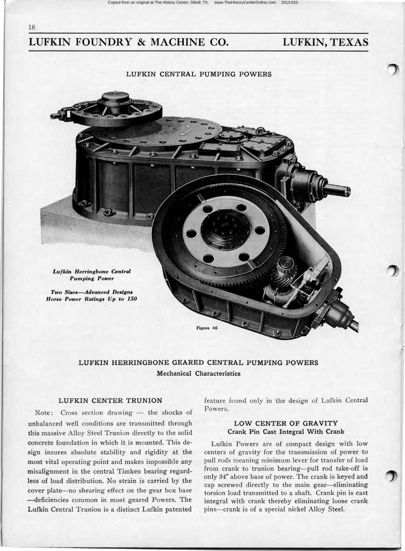
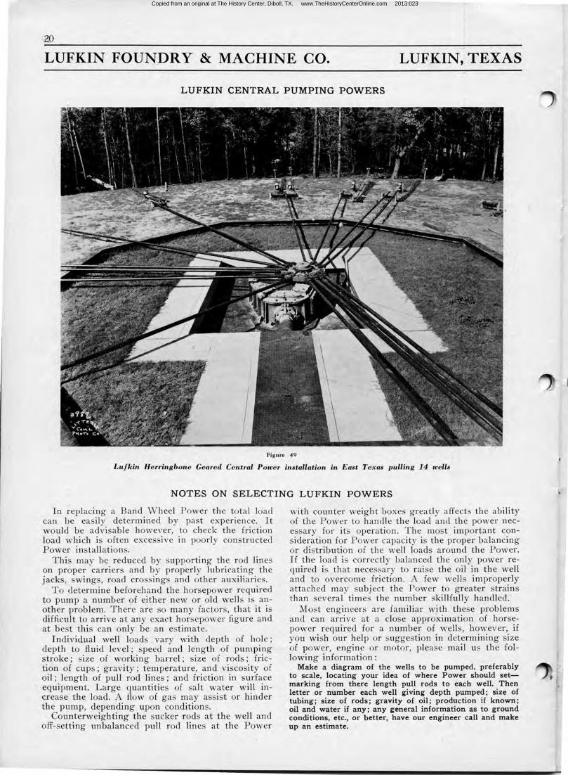
LUFKIN CENTRAL PUMPING POWERS
Lufkin Herringbone Central Pumping Power
Two Si:1e1- A.dvanced Deaign• Horse Power Rating1 Up to 150
Figure 46
LUFKIN HERRINGBONE GEARED CENTRAL PUMPING POWERS
Mechanical Characteristics
LUFKIN CENTER TRUNION
Note : Cross section drawing - the shocks of
unbalanced well conditions are transmitted through
this massive Alloy Steel Trunion directly to the solid
concrete foundation in which it is mounted. This de
sign insures absolute stability and rigidity at the
most vital operating point and makes impossible any
misalignment in the central Timken bearing regard
less of load distribution. No strain is carried by the
cover plate- no shearing effect on the gear box base
-deficiencies common in most geared Powers. The
L ufkin Central T runion is a distinct Lufkin patented
feature found only in the design of Lufkin Central Powers.
LOW CENTER OF GRAVITY Crank Pin Cast Integral With Crank
Lufkin Powers are of compact design with low centers of gravity fo r the transmission of power to pull rods meaning minimum lever for transfer of load from crank to trunion bearing-pull rod take-off is only 34" above base of power. The crank is keyed and cap screwed directly to the main gear-eliminating torsion load transmitted to a shaft. Crank pin is cast integral with crank thereby eliminating loose crank pins- crank is of a special nickel Alloy Steel.
Copied from an original at The History Center, Diboll, TX. www.TheHistoryCenterOnline.com 2013:023
19
LUFKIN FOUNDRY & MACHINE CO. LUFKIN, TEXAS
LUFKIN CENTRAL PUMPING POWERS
~~~,~INGBONE GEAR ELIMINATES .. . . . . THRUST LOAD
Easy Adjustability
Herringbone main gear equalizes all gear thrust load insuring longer bearing life. A Lufkin patented feature permits easy adjustability, in the field, of both Herringbone and Gleason Helical bevel gears.
ANTI-FRICTION BEARINGS THROUGHOUT
All bearings are Timken Roller Bearings of generous size with high load carrying capacities.
GENERAL SPECIFICATIONS
Herringbone Units
1. Lufkin-Sykes Herringbone Main Gears.
2. Gleason Helical Bevel Gears.
3. Nickel-Alloy Massive Steel Trunion.
4. Low Center Gravity- compact.
5. Pressure P ump L ubrication-Positive.
6. Timken equipped throughout.
7. Crank Pin cast integral with crank.
8. No housing expense except for prime mover.
9. Designed throughout with conservative wear formulas-rugged-strong-for long lasting service.
Ask for special bulletin.
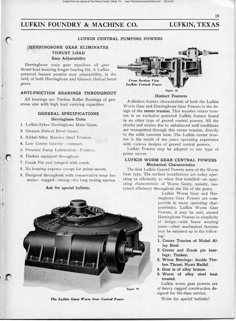
Cross Section View Lufkin Central Power
Figure 4 8
Distinct Features
A distinct feature characteristic of both the Lufkin Worm Gear and Herringbone Gear Powers is the design of the center trunion. This massive ·center-trunion is an exclusive patented Lufkin feature found in no other type of geared central powers. All the shocks and strains due to unbalanced well conditions are transmitted through this center trunion, directly to the solid concrete base. The Lufkin center trunion is the result of ten years operating experience with various designs of geared central powers.
Lufkin Powers may be adapted to any type of prime mover.
LUFKIN WORM GEAR CEN1TRAL POWERS Mechanical Characteristics
The first Lufkin Geared Powers were of the Worm Gear type. The earliest installations are today operating as efficiently as when first installed- an operating characteristic of Worm Gears, namely, sustained efficiency throughout the life of the gears. · Lufkin W orni Gear and Her-
ringbone Gear Powers are comparable in many operating characteristics. Lufkin Worm Gear Powers, it may be said, exceed Herringbone Powers in simplicity of design- with fewer wearing parts-other mechanical features may be summed up in the following: 1. Center Trunion of Nickel Al
loy Steel. 2. Center and Crank pin bear
ings ; Timken. 3. Worm Bearings : double T im
ken Thrust, H yatt Radial. 4. Gear is of alloy bronze. 5. Worm of alloy steel heat
treated. Lufkin worm gear powers are
of heavy rugged construction designed for life-time service.
The Lufkin Giant Worm Gear Central Power Write for special bulletin!
Copied from an original at The History Center, Diboll, TX. www.TheHistoryCenterOnline.com 2013:023
~o
LUFKIN FOUNDRY & MACHINE. CO. LUFKIN,: TEXAS
LUFKIN CENTRAL PUMPING POWERS
Figure 49
Lufkin Herringbone Geared Central Power installation in East Texas pulling 14 wells
NOTES ON SELECTING LUFKIN POWERS
In replacing a Band Wheel Power the total load can be easily determined by past experience. It would be advisable however, to check the friction load which is often exces ive in poorly con tructed Power in tallations.
This may be reduced by supporting the rod line on proper carrier and by properly lubricating the jacks, wings, road cro sings and other auxiliaries.
To determine beforehand the hor epower required to pump a number of either new or old wells is another problem. There are o many factor , that it is difficult to arrive at any exact hor epower figure and at be t this can only be an estimate.
Individual weli loads vary with depth of hole; depth to fluid level; speed and length of pumping stroke; size of working barrel; ize of rod ; friction of cups; gravity; temperature, and viscosity of oil; length of pull rod lines ; and friction in surface equipment. Large quantitie of salt water will increase the load. A flow of ga may assist or hinder the pump, depending upon conditions. ,
Counterweighting the sucker rods at the well and off- etting unbalanced pull rod lines at the Power
with counter weight boxe greatly affects the ability of the Power to handle the load and the power necessary for its operation. The mo t important consideration for Power capacity is the proper balancing or distribution of the well loads around the Power. If the load i correctly balanced the only power required i that necessary to raise the oil in the well and to overcome friction. A few wells improperly attach ed may subject the Power to greater strains than several times the number skillfully handled.
Most engineers are familiar with the. e problems and can arrive at a close approximation of horsepower required for a number of wells, however, if you wish our help or suggestion in determining size of power, engine or motor, please mail us the following information:
Make a diagram of the wells to be pumped, ·preferably to scale, locating your idea of whe·re Power should setmarking from there length pull rods to each well. Then letter or number each well giving depth pumped ; size of tubing; size of rods ; gravity of oil; production if known ; oil and water if any; any general information as to ground conditions, etc., or better, have our engineer call and make up an estimate.
(
Copied from an original at The History Center, Diboll, TX. www.TheHistoryCenterOnline.com 2013:023
J
21
LUFKIN FOUNDRY & MACHINE CO. LUFKIN, TEXAS
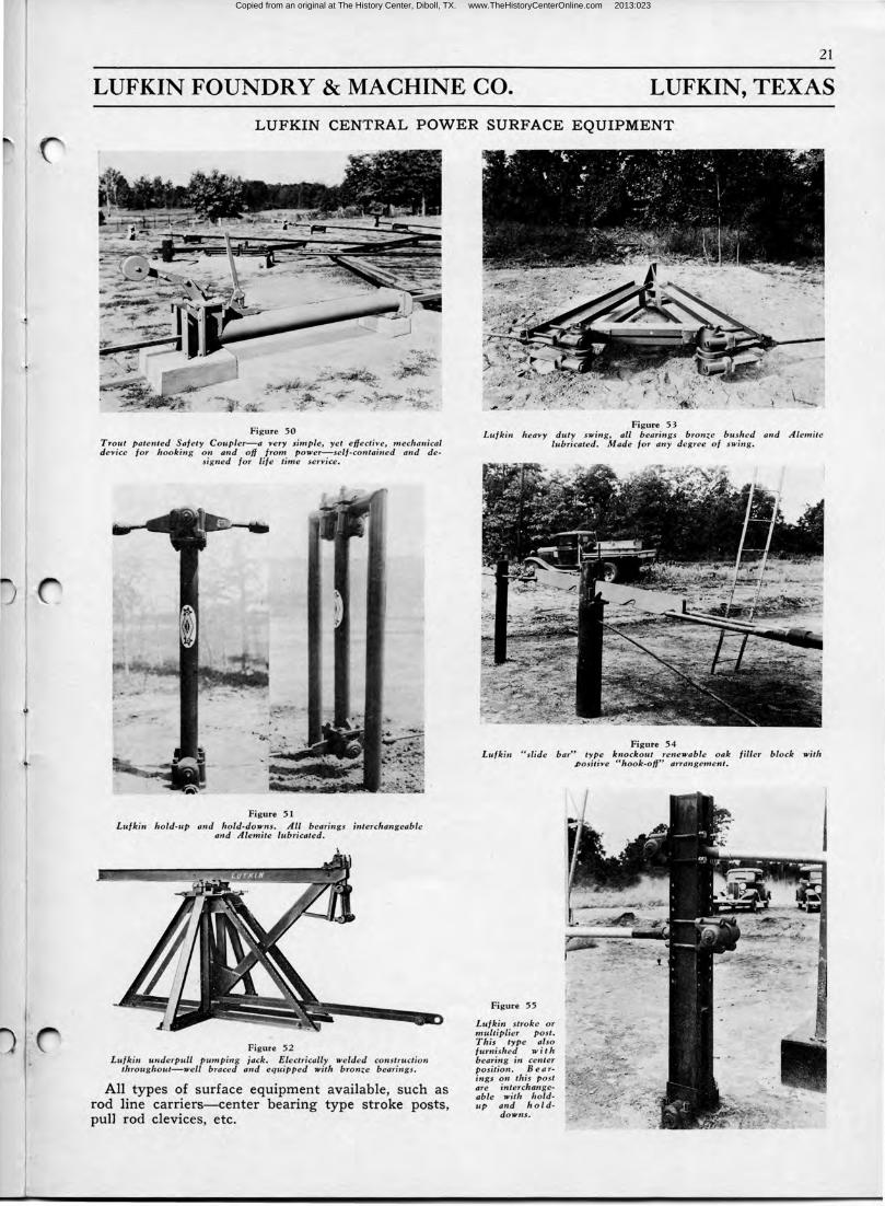
LUFKIN CENTRAL POWER SURFACE EQUIPMENT .
Figure 50 Trout patented Safety Coupler-a 'l'ery simple, yet effecti'l'e, mechanical device for hooking on and off from power-self-contained and de
signed for life time service.
Figure 51 Lufkin hold-up and hold-downs. All bearings interchangeable
and Alemite lubricated.
Figure 52 Lufkin underpull pumping jack. Electrically welded construction
throughout-well braced and equipped with bronze bearings.
All types of surface equipment available, such as rod line carriers-center bearing type stroke posts, pulJ rod clevices, etc.
Figure 53 Lufkin heavy duty swing, all bearings bronze bushed and Alemite
lubricated. Made for any degree of swing.
Figure 54 Lufkin "slide bar" type knockout renewable oak filler block with
,Positive " hook-off" arrangement.
Figure 55
Lufkin stroke or multiplier post. This type also furnished with bearing in center position. B e a rings on this post are interchangeable with holdup and hold-
downs.
Copied from an original at The History Center, Diboll, TX. www.TheHistoryCenterOnline.com 2013:023
22
LUFKIN FOUNDRY & MACHINE CO. LUFKIN, TEXAS
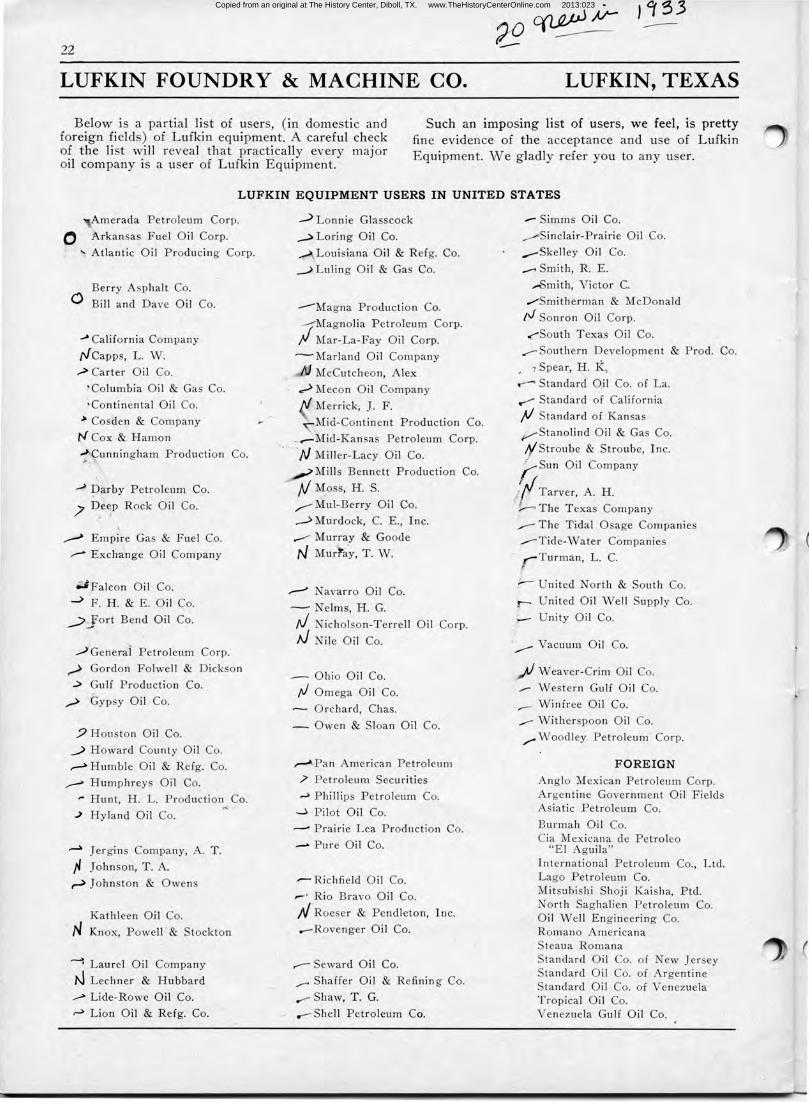
Below is a partial list of users, (in domestic and foreign fields) of Lufkin equipment. A careful check of the list will reveal that practically every major oil company is a user of Lufkin Equipment.
Such an imposing list of users, we feel, is pretty fine evidence of the acceptance and use of Lufkin Equipment. We gladly refer you to any user.
LUFKIN EQUIPMENT USERS IN UNITED STATES
Amerada Petroleum Corp.
O Arkansas Fuel Oil Corp.
'- Atlantic Oil Producing Corp.
Berry Asphalt Co. 0 Bill and Dave Oil Co.
..J> California Company
rJ Capps, L. W.
.> Carter Oil Co.
'Columbia Oil & Gas Co.
"Continental Oil Co.
> Cosden & Company
t'f Cox & Hamon
:>'Cunningham Production Co.
_,j :parby Petroleum Co.
)' Deep Rock Oil Co.
,,........> Empire Gas & Fuel Co.
,,..- Exchange Oil Company
.;;Falcon Oil Co.
......:> F. H. & E. Oil Co.
_;>Jort Bend Oil Co.
./General Petroleum Corp.
,-> Gordon Folwell & Dickson
..> Gulf Production Co.
,,,_.> Gypsy Oil Co.
5J Houston Oil Co.
....> Howard County Oil Co.
,,..-> Humble Oil & Rdg. Co.
,,...-> Humphreys Oil Co.
,. Hunt, H. L. Production Co.
.> Hyland Oil Co.
~ J er gins Company, A . T.
fl Johnson, T. A.
~ J ohriston & Owens
Kathleen Oil Co.
N Knox, Powell & Stockton
~ Laurel Oil Company
N Lechner & Hubbard
,.....> Lide-Rowe Oil Co.
~ Lion Oil & Ref g. Co.
--"> Lonnie Glasscock
~Loring Oil Co.
.-A_ Louisiana Oil & Ref g. Co.
__.) Luling Oil & Gas Co.
--Magna Production Co.
~Magnolia Petroleum Corp.
I" Mar-La-Fay Oil Corp.
~Marland Oil Company
lfJ McCutcheon, Alex
.,,.> Mecon Oil Company
Merrick; J. F.
.Mid-Continent Production Co.
_,.-Mid-Kansas Petroleum Corp.
)v Miller-Lacy Oil Co.
_/Mills Bennett Production Co.
· /J :rv.t;oss, H. S.
_,,--Mul-Berry Oil Co.
,--'> Murdock, C. E., Inc.
...--- Murray & Goode
N Mur'ra.y, T. W.
.---> Navarro Oil Co.
-- Nelms, H. G.
r.J Nicholson-Terrell Oil Corp.
Af Nile Oil Co.
- Oh io Oil Co .
rJ Omega Oil Co.
- Orchard, Chas.
- Owen & Sloan Oil Co.
,,...-lPan American Petroleum
/ Petroleum Securities
,.j Phillips Petroleum Co.
~ Pi lot Oil Co .
...- Prairie Lea Production Co.
- Pure Oil Co.
-- Richfield Oil Co.
.- · Rio Bravo Oil Co.
N Roe er & Pendleton, Inc.
--Revenger Oil Co.
.-- Seward Oil Co.
,,,.._, Shaffer Oil & Refining Co.
.,,..- Shaw, T. G.
Shell Petroleum Co.
- Simms Oil Co.
..-"'Sinclair-Prairie Oil Co.
....-Skelley Oil Co.
_., Smith, R. E.
,..,Smith, Victor C. ......... ·Smitherman & McDonald
/V Sonron Oil Corp.
<South Texas Oil Co .
,...-Southern Development & Prod. Co.
, 1 Spear, H. I(
.--' Standard Q,il Co. of La .
< Standard of California
}/ Standard of Kansas
~Stanolind Oil & Gas Co.
;y' Straube & Straube, Inc. t Sun Oil Company
/I Tarver, A. H. ::,.....-, The Texas Company
,,.,..-- The Tidal Osage Companies
__..,Tide-Water Companies
. r Turman, L. C.
;....- United North & South Co .
r- United Oil Well Supply Co .
Unity Oil Co.
·,..........--Vacuum Oil Co .
~Weaver-Crim Oil Co.
,...-.. Western Gulf Oil Co.
,,-- Winfree Oil Co.
.,....- Witherspoon Oil Co.
,..... Woodley Petroleum Corp .
FOREIGN
Anglo Mexican Petroleum Corp. Argentine Government Oil Fields A iatic Petroleum Co.
Burrnah Oil Co . Cia Mexicana de Petroleo
"El Agui la" International Petroleum Co., Ltd. Lago Petroleum Co. Mitsubishi Shoji Kaisha, Ptd . North Saghalien Petroleum Co. Oi l Well Engineering Co. Romano Americana Steaua Romana Standard Oil Co. of ew Jersey Standard Oil Co. of Argentine Standard Oi l Co. of Venezuela Tropical Oil Co. Venezuela Gulf Oil Co.
(
(
Copied from an original at The History Center, Diboll, TX. www.TheHistoryCenterOnline.com 2013:023
23
LUFKIN FOUNDRY & MACHINE CO. LUFKIN, TEXAS
Copied from an original at The History Center, Diboll, TX. www.TheHistoryCenterOnline.com 2013:023
LUFKIN EQUIPMENT OF ADVANCED DESIGN
Copied from an original at The History Center, Diboll, TX. www.TheHistoryCenterOnline.com 2013:023