copper removal using ion exchanger flat sheet …umpir.ump.edu.my/11022/1/fkksa - kiew fong fong...
TRANSCRIPT

III
COPPER REMOVAL USING ION EXCHANGER
FLAT SHEET MIXED MATRIX MEMBRANE:
EFFECT OF POLYETHERSULFONE
COMPOSITION ON MEMBRANE PROPERTIES
KIEW FONG FONG
Thesis submitted in partial fulfilment of the requirements
for the award of the degree of
Bachelor of Chemical Engineering
Faculty of Chemical & Natural Resources Engineering
UNIVERSITI MALAYSIA PAHANG
JANUARY 2015
©KIEW FONG FONG (2015)

VIII
ABSTRACT
Ion exchanger has been widely used and applied in removal of heavy metal in wastewater
treatment. In the current study, mixed matrix membrane (MMM) ion exchanger was
developed by incorporating Amberlite IR120H into polyethersulfone (PES) dope polymer
solution for copper removal. The effect of PES composition in dope polymer solution was
varied from 23wt%, 25wt%, 28wt% and 30wt% at constant amount of 20g Amberlite
IR120. The performance of membrane was evaluated using batch binding and cross flow
filtration. In batch binding, the highest static binding capacity of the copper removal was
achieved by membrane prepared from 30wt% PES with the binding efficiency at a value
of 64% from 500ppm standard solution of copper (II) sulphate pentahydrate. In cross flow
filtration, 30wt% PES membrane has the maximum binding efficiency at 95%.
Regeneration study was studied with 30w%t PES membrane using 10%HCL elution
solution in three consecutives running cycle. The membrane can be regenerated with 97%
binding efficiency in each 3 cycles meaning all the membrane produced can be
regenerated. As a conclusion, the higher the composition of PES membrane, the higher
the adsorptive performance, thus 30wt% PES membrane was the optimum PES
composition.

IX
ABSTRAK
Penukar ion telah digunakan secara meluas dan digunakan dalam penyingkiran logam
berat di dalam rawatan air sisa. Dalam kajian semasa, membran matriks campuran
(MMM) penukar ion telah dibangunkan dengan menggabungkan Amberlite IR120H ke
dalam larutan polimer polyethersulfone (PES) dadah untuk penyingkiran kuprum. Kesan
komposisi PES dalam larutan polimer telah diubah dari 23wt%, 25wt%, 28wt% dan
30wt% pada jumlah berterusan 20g Amberlite IR120. Prestasi membran telah dinilai
menggunakan mengikat kelompok dan penapisan aliran silang. Dalam kelompok
mengikat, kapasiti tertinggi statik mengikat penyingkiran kuprum yang telah dicapai oleh
membran yang disediakan daripada 30wt% PES dengan kecekapan yang mengikat pada
nilai 64% daripada penyelesaian standard 500ppm kuprum (II) sulfat pentahydrate.
Dalam penapisan aliran silang, 30wt% membran PES mempunyai maksimum yang
mengikat kecekapan pada 95%. Kajian semula telah dikaji dengan 30W% t membran PES
menggunakan 10% HCL penyelesaian elution dalam tiga consecutives berjalan kitaran.
Membran yang boleh dijana semula dengan 97% kecekapan mengikat dalam setiap 3
kitaran yang bermaksud semua membran yang dihasilkan boleh dijana semula. Sebagai
kesimpulan, komposisi yang lebih tinggi membran PES, lebih tinggi prestasi serapan
yang, oleh itu 30wt% membran PES adalah komposisi PES optimum.

X
TABLE OF CONTENTS
SUPERVISOR’S DECLARATION ....................................................................... IV STUDENT’S DECLARATION ............................................................................. V Dedication .......................................................................................................... VI ACKNOWLEDGEMENT ................................................................................... VII ABSTRACT ..................................................................................................... VIII ABSTRAK ......................................................................................................... IX TABLE OF CONTENTS ...................................................................................... X
LIST OF FIGURES ............................................................................................ XII LIST OF TABLES ............................................................................................. XIII LIST OF ABBREVIATIONS ............................................................................. XIV
1. INTRODUCTION .......................................................................................... 15
1.1 Motivation and statement of problem .................................................. 15 1.2 Objectives ........................................................................................... 18 1.3 Scope of this research ........................................................................ 18
1.4 Organisation of this thesis ....................................................................... 18
2. LITERATURE REVIEW ................................................................................ 20
2.1 Overview ............................................................................................. 20 2.2 Removal Mechanisms ......................................................................... 20
2.3 Membrane Classification ..................................................................... 24 2.4 Mixed Matrix Membrane (MMM) ......................................................... 26
2.5 Cross Flow Filtration in Flat Sheet Membrane .................................... 35 2.6 Summary ................................................................................................. 36
3. MATERIALS AND METHODS ...................................................................... 38
3.1 Overview ............................................................................................. 38
3.2 Introduction ......................................................................................... 38 3.3 Chemicals ........................................................................................... 38 3.4 Production of Flat Sheet Membrane ................................................... 39
3.5 Membrane Structure Characterisation/Morphology of Flat Sheet ....... 45 3.6 Batch Static Binding Experiment ......................................................... 45 3.7 Cross Flow Filtration ........................................................................... 49
3.8 Comparison Binding Efficiency Between Batch Binding and Cross Flow Filtration ........................................................................................................ 51
3.9 Summary ................................................................................................. 51
4. RESULTS AND DISCUSSION ....................................................................... 52
4.1 Overview ............................................................................................. 52 4.2 Production of Flat Sheet Mixed Matrix Membrane .............................. 52 4.3 Batch Static Binding Capacity ............................................................. 55
4.4 Cross Flow Filtration ........................................................................... 59 4.5 Comparison Binding Efficiency Between Batch Binding and Cross Flow Filtration ........................................................................................................ 63
5. CONCLUSION .............................................................................................. 64
5.1 Conclusion .......................................................................................... 64
5.2 Future work ......................................................................................... 65
REFRENCES ..................................................................................................... 66
APPENDICES ................................................................................................... 70

XI
......................................................................................................................... 70

XII
LIST OF FIGURES
Figure 2-1: Types of ion exchanger. ............................................................................... 23
Figure 2-2: Principle of Ion Exchange Chromatography (salt gradient elution) (Media,
2014). .............................................................................................................................. 24
Figure 2-3: Schematic representation of various morphologies (M.H.V. Mulder, 1996).
........................................................................................................................................ 25
Figure 2-4: Mixed Matrix Membrane (Chung et al., 2007). ........................................... 26
Figure 2-5: Dead End Microfiltration (Spring & Hashsham, 2006). .............................. 36
Figure 2-6: Cross Flow Microfiltration (Orporation, 2002). .......................................... 36
Figure 3-1: Drying of Amberlite IR120 resin. ................................................................ 39
Figure 3-2: Grinded and sieved resin. ............................................................................. 40
Figure 3-3: PES/NMP/PVP solution ............................................................................... 42
Figure 3-4: Mixed Matrix Membrane after mixing of 20g of Amberlite IR120 with
PES/NMP/PVP. .............................................................................................................. 42
Figure 3-5: Casting Process ............................................................................................ 43
Figure 3-6: Detaching Process after casting for 1.5 minutes .......................................... 44
Figure 3-7: Membrane after detached immersed in water-bath. ..................................... 44
Figure 3-8: Buffer solution for calibration. .................................................................... 46
Figure 3-9: Buffer solution for pH 4.01. ......................................................................... 46
Figure 3-10: Buffer solution for pH 7.00. ....................................................................... 47
Figure 3-11: Buffer solution for pH 9.00. ....................................................................... 47
Figure 3-12: Cross flow machine. ................................................................................... 50
Figure 4-1: SEM of 23% PES ......................................................................................... 53
Figure 4-2: SEM of 25% PES ......................................................................................... 53
Figure 4-3: SEM of 28% PES ......................................................................................... 54
Figure 4-4: SEM of 30% PES ......................................................................................... 54
Figure 4-5: pH of Copper (II) sulphate pentahydrate ..................................................... 55
Figure 4-6: biosan Multi rotator RS-60 .......................................................................... 56
Figure 4-7: Centrifuged tubes ......................................................................................... 56
Figure 4-8: Titan3TM 0.45µm of reg cellulose membrane filters .................................. 57
Figure 4-9: Comparison Removal Efficiency of Cu with different PES compositions .. 58
Figure 4-10: Comparison Binding Efficiency Using Batch Binding And Cross Flow
Filtration .......................................................................................................................... 63

XIII
LIST OF TABLES
Table 1-1: The MCL standards for the most hazardous heavy metals in wastewater .... 16
Table 2-1: Comparison of technologies used for heavy metal removal from wasterwater
(Farooq et al., 2010). ...................................................................................................... 20
Table 2-2: Pressure driven membrane processes(M.H.V. Mulder, 1996). ..................... 26
Table 2-3: Comparison of different adsorbents used in the treatment of wastewaters
(Lena Johansson Westholm, 2014) ................................................................................. 29
Table 2-4: List of Common Ions in Wastewater (Anions, 2014). .................................. 33
Table 2-5: Characteristics of Commercial Cation Exchange Resin (E.Dabrowski et al.,
2004). .............................................................................................................................. 33
Table 2-6: Characteristics of Amberlite IR120 (Alguacil, Alonso, & Lozano, 2004) ... 35
Table 3-1: Various concentration of PES concentration in polymer membrane solution
........................................................................................................................................ 41
Table 3-2: Summary parameters for casting membrane ................................................. 43
Table 4-1: Average of Triplicate Batch Adsorption of Copper ...................................... 58
Table 4-2: Average of Triplicate Batch Elution Buffer for Copper using 10% HCL .... 59
Table 4-3: Water Compaction Flux,PWP for Single Cycle Cross Flow Filtration
(ml/bar.cm².sec) .............................................................................................................. 60
Table 4-4: Cross Flow Filtration Binding for Single Cycle using 100ppm of Copper
(II) Sulphate Pentahydrate .............................................................................................. 60
Table 4-5: Water Compaction Flux,PWP Cross Flow Filtration (ml/bar.cm².s) ............ 62
Table 4-6: Triplicate Cycle Cross Flow Filtration for Adsorption and Elution .............. 62
Table 4-7: Comparison Binding Efficiency From Batch Binding and Cross Flow
Filtration .......................................................................................................................... 63

XIV
LIST OF ABBREVIATIONS
AAS Atomic Adsorption Spectroscopy
MLC Maximum Contaminant Level
MMM Mixed Matrix Membrane
MF Microfiltration
NMP N-methylpyrolidone
PES Polyethersulfone
PVP Polyvinvylpyrrolidone
PWP Water Permeation Flux
SEM Scanning Electron Microscope
Wt Weight Fraction

15
1 INTRODUCTION
1.1 Motivation and statement of problem
Water of high quality is essential to human life and water of acceptable quality is essential
for agriculture, industrial, domestic and commercial uses. Heavy metal contamination
wastewater has turn into one of the most serious environmental problems. Heavy metal
included ferrous metals and non-ferrous metals. Ferrous metals containing steel, casting
and wrought iron while non-ferrous metals containing copper, brass, nickle and zinc
(Gorilla, 2013). Differ from organic pollutants, almost all of the heavy metal are not
degradable and toxic to living organisms. Heavy metal contamination exists in many
industries for instance metal plating, mining operations, tanneries, chloro-alkali, radiator
manufacturing, smelting, alloy industries and storage batteries industries (Hala Ahmed
Hegazi, 2013).
Copper is one of the vital trace element required by humans for its role in enzyme
synthesis, tissues and bone development. However, it becomes toxic and carcinogenic
when a large amount is ingested (Sibel Tunali Akara et al., 2009). Copper can be applied
in a variety of product. It can be used as prevalent in water and wastewater systems, as
algae controller in reservoirs, as common material in household plumbing and root killer
in underground pipes (Less, 2012). Copper can also be found in industrial effluent in acid
mine drainage, galvanizing plants, natural ores and municipal wastewater treatment plant
which can constitute to serious health hazards. Since copper is non-biodegradable, its
toxicity found at the level of 100-500ppm per day in human being could travel through
food chain via bioaccumulation. According to World Health Organization 2006, the
limitation for copper concentration that can reach its maximum in drinking water is
1.5ppm (Muzenda et al., 2011) and only allowable for not exceeding 1.3ppm in industrial
effluents (Muhammad Bilal et al., 2013). In human, copper can cause liver deposition,
vomiting, headache, nausea, respiratory problems, abdominal pain, liver, kidney failure
and gastrointestinal bleeding. Large amount of copper in fresh water resources and
aquatic ecosystem will damage the osmo-regulatory mechanism of fresh water animals
and cause mutagenesis in human. Therefore, heavy metal wastewater needed to be treated
for safer drinking water and discharged into freshwater bodies for safer human
consumption. Table 1.1 showed the maximum contaminant level (MLC) standards of

16
hazardous heavy metal with copper ranked the second highest MCL in wastewater
(Mukesh Parmar and Lokendra Singh Thakur, 2013).
Table 1-1: The MCL standards for the most hazardous heavy metals in wastewater
Heavy
metal Toxicities
MCL
(mg/L)
Arsenic Skin manifestations, visceral cancers, vascular disease 0.05
Cadmium Kidney damage, renal disorder, human carcinogen 0.01
Chromium Headache, diarrhea, nausea, vomiting, carcinogenic 0.05
Copper Liver damage, Wilson disease, insomnia 0.25
Nickel Dermatitis, nausea, chronic asthma, coughing, human
carcinogen 0.2
Zinc Depression, lethargy, neurological signs and increased thirst 0.8
Lead Damage the fetal brain, diseases of the kidneys, circulatory
system, and nervous system 0.006
Mercury Rheumatoid arthritis, and diseases of the kidneys, circulatory
system, and nervous system 0.00003
There is growing concern about the pollution of heavy metals and residents are
demanding for cleaner environment. The current review deals with all the available
treatment technologies for copper removal to ensure environmental safety.
There are several technologies used to treat the copper waste water. These include
chemical precipitation, chemical coagulation, ion-exchange, adsorption and membrane
filtration. Each and every types of technologies has its own advantages and limitations.
In the current study, a combination of ion exchange and membrane filtration was
developed in the removal of copper in the study of PES composition toward the
adsorption capacity.
Ion exchange is one of the methods that have been widely used in heavy metal waste
removal as it is easily regenerated and has high removal efficiency with low running costs
(Considine, 2005). Membrane filtration is providing high filtration efficiency with
microfiltration (Fu & Wang, 2011). Microfiltration (MF) membranes have become the
main focus as promising separation tool in several industrial processes, covering
fractionation and concentration steps in pure water production and in water and
17
wastewater treatments (M.Cheryan, 1998) . Although many methods have been proposed
to improve the separation performance, the heart of microfiltration processes is the
membrane itself. Important characteristics for achieving high performance microfiltration
are high flux in combination with desired selectivity and low fouling. Because of their
mechanical strength, thermal and chemical stability as well as excellence film forming
properties, sulfone polymer which is polyethersulfone (PES), have been used very often
for the fabrication of high performance commercial microfiltration membranes
(H.Susanto, 2009). The concept of ion exchanger using Amberlite IR 120 resin will be
explained on how the uptake of copper ions by the hollow fiber membrane application. A
grinded Amberlite IR120 cation resin were blended with Polyethersulfone (PES) polymer
solution for the making of adsorptive hollow fiber membrane. The effect of PES
concentration on the performance of the membrane were being investigated.
Adsorption is the most commonly used technology in treating effluent as it has been
known as one of an effective and economic method for heavy metal treatment. Due to its
reversible process, the potential adsorption by using mixed matrix membrane is
economical as the adsorption agents increase its performance while decreasing treatment
cost (Fu & Wang, 2011). In the current technique used, cation resins are the adsorbent
due to its unique properties on ion exchange capability. Other than that, different types of
adsorbent will be compared in the literature review.
Even though the technologies have large adsorption capacity, packed membrane
chromatography in the module has high pressure drop, limited flow rate and flow
channeling but it has been proved that it is a successful tool in separating ion effluents.
Ion exchange chromatography is mostly applied in protein separation. The principle
involved electrostatic interaction between macromolecules and adsorbents. There are two
types of ion exchange membranes which are anion and cation exchanger. Cation exchange
membranes has not been widely used in effluent treatment as it is still a new technology
(Borneman, 2006). Therefore, in the current research, the feasibility of mixed matrix
membrane for copper ions removal was studies.

18
1.2 Objectives
The objective of this research is to study the effect of PES concentration on the
performance adsorptive flat sheet mixed matrix membrane for copper removal.
1.3 Scope of this research
The scopes of this research are as follow:
i) To produce adsorptive flat sheet MMM by incorporating cation resin,
Amberlite IR120 into a polymer solution consists of PES, NMP and PVP.
ii) To characterize the MMM in term of pore structure, water permeability and
static adsorption properties for copper removal.
iii) To compare the performance of the membrane using batch binding and cross
flow filtration.
iv) To investigate the regeneration of MMM.
1.4 Organisation of this thesis
The structure of the reminder of the thesis is outlined as follow:
Chapter 2 provides a description of the removal mechanism, principle of ion exchanger,
membrane classification, mixed matrix membrane, selection of polymer and resin
contents, types of adsorbents used and cross-flow filtration in flat sheet membrane A
general description on the technologies used and the ion exchange concept in adsorption
of copper ions are presented with briefly describing the adsorption capacity. This chapter
also provides a brief discussion of the types of membranes available for heavy metal
removal, mentioning their strengths and limitations. A summary of the previous
experimental work on preparation of dope solution is also presented.
Chapter 3 gives a review the methodology of the overall experiments. In this chapter, the
chemicals used in preparation of dope solution with various types of concentration of PES
on performances of flat sheet membrane is being reviewed with two different mechanisms
which are batch experiment and cross flow filtration. The calculation for water flux using
formula, morphological structure of membrane using Scanning Electron Microscope
(SEM) and static adsorption capacity and cross flow filtration using Atomic Absorption
Spectroscopy (AAS) are presented and compared.

19
Chapter 4 is devoted in testing the performance on different types of composition
membrane being produced. A brief review of the morphological on pore structure is also
presented. The adsorption capacity of copper ions by different PES concentration is being
studied and compared by determining from its adsorption efficiency from both batch
experiment and cross flow filtration. A detailed description of the water permeability
testing is also outlined.

20
2 LITERATURE REVIEW
2.1 Overview
This paper presents the description of the removal mechanisms with their advantages and
limitations, membrane classification, mixed matrix membrane, selection of polymer
contents, types of adsorbents, selection of cation resins, principle of ion exchanger and
cross flow filtration. A general description on the technologies used and the ion exchange
concept in adsorption of copper ions are presented. This paper will present the reasons of
using combination of ion exchange and membrane adsorption filtration membrane, types
of membrane used, chemical usages and adsorbents used in the production of flat sheet
membrane.
2.2 Removal Mechanisms
There are different types of wastewater treatment technologies which are chemical
precipitation, coagulation, ion exchange, adsorption and membrane filtration. Table 2-1
showed a comparison of technologies used for heavy metal removal from wastewater.
Table 2-1: Comparison of technologies used for heavy metal removal from wasterwater
(Farooq et al., 2010).
Technologies Advantages Limitations
Chemical
Precipitation
Simple
Inexpensive
Most of the metals can
be removed
Large amount of
sludge produced
Disposal problem
Chemical
Coagulation
Sludge settling
Dewatering
High cost
Large consumption of
chemicals
Ion-exchange High regeneration of
materials
Metal selective
High cost
Less number of metal
ions recovered

21
Adsorption using
activated carbon
Most of metals can be
removed
High efficiency(99%)
Cost of activated
carbon
No regeneration
Performance depends
upon adsorbent
Membrane Filtration Less solid waste
produced
Less chemical
consumption
High efficiency
(>95% for sngle
metal)
High initial and
running cost
Low flow rates
Percentage removal
decreases with the
presence of other
metals.
Most of the heavy metal wastewater treatment industry is using ion exchange as the
solution. Ion exchange is one of the methods that have been widely used in heavy metal
waste removal as it is easily regenerated and has high removal efficiency with low
running costs (Considine, 2005). Other than that, ion exchanger is one of the promising
approach technique in effectively removing and recovery of targeted metal using ion
exchange resins to exchange cation with wastewater metals (Bilal et al., 2013). Since ion
exchange is a reversible chemical reaction, it will be used to study the adsorption and
regeneration of ions using membrane (Mukesh Parmar and Lokendra Singh Thakur,
2013).
Not only that, the advantage in using ion exchange is contaminated ions can be
regenerated. However, there are some limitations in ion exchange. (Practices, Treatment,
Treatment, & Options, 1996). During regeneration, water that are not de-ionised
containing calcium ions, when acid reacts with calcium ions will form calcium sulphate
precipitates that can block the pipe. Therefore, cation resin must be washed with de-
ionised water before usage. Not only that, iron fouling will occur since copper ions are
using in the research which clogs resin beads and prevent ion exchange (Considine, 2005).
Not to worry, ion exchange technology has high treatment and removal capacity and fast
kinetic (Kang et al., 2004) . Synthetic resin will be used as it has better adsorptive capacity
in removal of heavy metal (Alyüz et al., 2009).

22
Membrane filtration can be used for the treatment inorganic effluent, suspended solid,
organic compounds and also inorganic contaminant heavy metals. Membrane filtration is
defined as using membrane polymer with different properties using adsorption capability.
Membrane filtration is a physical barrier that restricts the passage of materials. Membrane
has four separation processes which are ultrafiltration, reverse osmosis, nanofiltration and
microfiltration. In our study, microfiltration flat sheet membrane is selected as our ions
are very tiny. Microfiltration (MF) is the technique in removing components in the range
of 0.025µm to 10.0µm by using microporous membrane filter (Spring & Hashsham,
2006). Or in short, microfiltration is a conventional filtration that remove particles smaller
than a micron such as colloids and bacteria that came with the definition on microfiltration
refers to filtration process that use porous membrane to separate suspended particles with
diameter between 0.1 to 10µm (R.W. Baker, 2004). Membrane can be manufactured in
flat sheet, hollow fiber, spiral and tubular in shape. Flat sheet membrane itself can
withstand back pressure with high membrane packing density, providing high flexibility
and high efficiency in filtering large volume of liquid while providing minimum space
and energy(Chemical & Group, 2014)
Thus, membrane filtration is chosen with combining ion exchange technology in the
research because of its high separation efficiency of more than 95% for a single ion metal
removal with high regeneration of materials which can save cost (Farooq et al., 2010),
easy operation and space saving (Fu & Wang, 2011).
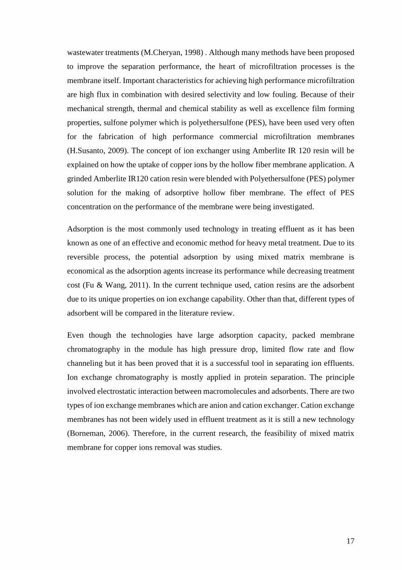
2.2-1 Principles of Ion Exchanger
Ion exchange is a reversible exchange of ions with ions in solution electrostatically bound
to an insoluble support matrix. There are two types of ion exchangers named anion
exchanger and cation exchanger as shown in Figure 2-1. Separation on ion exchange
chromatography columns is based on charged density.
23
Figure 2-1: Types of ion exchanger.
The matrix is based on organic compounds and synthetic resins. There are five stages in
ion exchange chromatography. There are starting conditions, adsorption of samples
substances, start of desorption, end of desorption and regeneration.
In first stage, the ion exchanger allows the binding of desired ions molecules on the active
site of cation resin. The negatively charged cation resin materials will be loaded with
hydrogen ion in solution.
In second stage, sample application and adsorption where solute molecules carrying the
charge displace counter-ions and bind reversibly to the resin. Ions, impurities and
hydrogen ions that are not bounded to the resin binding site will be washed out from
exchanger bed using starting buffer.
In third stage, ions are removed from column by changing to elution conditions
unfavourable for ionic bonding of solute molecules. Desorption is achieved by the
introduction of salt concentration gradient and solute molecules are released from column
in order of their strengths of binding where weak bound substances are being eluted first.
In fourth and last stage, elution will make the eluent will exchange and release the
valuable cation. At the same time, the resin will be regenerated. The ions concentration
before and after the process will be tested (Media, 2014) The overall stages are shown in
Figure 2-2.

24
Figure 2-2: Principle of Ion Exchange Chromatography (salt gradient elution) (Media,
2014).
2.3 Membrane Classification
A membrane is a selective barrier between two phases. Depending on the application,
different membrane morphologies were used and several types of membrane separation
mechanisms exist. In membrane applications where the solution diffusion mechanism
plays the major role, the membrane material is chosen based on the selective sorption and
diffusion properties, membrane morphology will be not the main factor to affect the
selectivity but it is still important as regarding to total flux (M.H.V. Mulder, 1996). Figure
2-3 showed the schematic representation of various morphologies.

25
Figure 2-3: Schematic representation of various morphologies (M.H.V. Mulder, 1996).
In all the membrane processes, driving force is essential to deliver the energy to separate
the feed molecules or particles; commonly applied driving force differences in pressure,
concentration, partial pressure, temperature or electrical potential. The most widely used
pressure driven processes are generally classified as microfiltration (MF), ultrafiltration
(UF) and hyperfiltration, which is normally subdivided in reverse osmosis (RO) and
nanofiltration (NF). Nevertheless, the difference between the processes is not always so
sharp, as presents in Table 2-2, summarizing the main characteristics of various
membrane processes, in which, typical permeability is for a typical permeate stream, i.e.,
with rejected species on the retentate side of the membrane.

26
Table 2-2: Pressure driven membrane processes(M.H.V. Mulder, 1996).
Membrane Process Typical Pressure
(bar)
Typical
permeability
(l/(m².h.bar)
Morpholoy of
selective layer
Microfiltration 0.1-2 >50 Porous
Ultrafiltration 1-5 10-50 Porous
Nanofiltration 5-20 1.4-12 Porous/ Dense
Reverse Osmosis 10-100 0.05-1.4 Dense
2.4 Mixed Matrix Membrane (MMM)
Mixed matrix membrane is the latest membrane morphology comprising of organic
polymer and inorganic particle phase as shown in Figure 2-4. Inorganic particles could
be zeolite, carbon molecular sieve or nano-size particles. Mixed matrix membranes are
known to have the ability of high selectivity, permeability or both relative to the existing
polymeric membranes, resulting from the addition of inorganic particles with their
inherent superior separation characteristics (Chung et al., 2007).
Figure 2-4: Mixed Matrix Membrane (Chung et al., 2007).
In this study, PES/NMP/PVP is the polymer phase while cation resin is the inorganic
phase. In olden time, mixed matrix membrane has been made in dense polymeric films in
gas transport facilitation through the membrane. A dope polymer solution is mixed
homogenized with cation resin before casting to produce flat sheet mixed matrix
membrane (Joao Miguel de Sousa Andre, 2009). It is called mixed matrix membrane
because of the mixing of dope polymer solution and cation resin. Mixed Matrix
Membrane is chosen in the study because of its high separation of heavy metal with low

27
costs, and functionality will not be lost when mixed matrix membrane are incorporative
with heavy metal (Joao Miguel de Sousa Andre, 2009).
2.4-1 Selection of Polyethersulfone (PES)/ N-methylpyrolidone
(NMP)/Polyvinvylpyrrolidone (PVP) As Polymer Membrane
Contents
In the preparation of membrane polymer content, Polyethersulfone (PES), N-
methylpyrolidone (NMP) and Polyvinvylpyrrolidone (PVP) were being selected to be
used. For the past of forty years, Polyethersulfone (PES) and Polysulfone (PSf) has been
widely used in Microfiltration (MF) and Ultrafiltration (UF) separation technology. PES
is more hydrophilic compared to PSf which is relatively hydrophobic (Lau et al., 1991).
Therefore, PES is selected as one of the element in membrane polymer. PES is the most
suitable membrane materials to be used in the study as it has good film-forming properties
and high thermal, chemical and biological resistance (Hofman & Pietrzak, 2013). Besides,
it can withstand heat resistance regardless of short term or long term in dependence of
half-life period of tensile strength, dimensional stability, creep resistance at high
temperature, impact resistance to notches and chemical resistance (Pes, 2014.). However,
PES has hydrophobic characteristic. But it can be overcome by adding additive such as
Polyvinvylpyrrolidone(PVP) to reduce the properties (Zhao, Xue, Ran, & Sun, 2013)
There are many different types of additives used in polymer membrane making. It
includes glycerol, BuOH, PEG and PVP. Journal proved that glycerol was not a good
choice to be used as additive and PEG has resulted sponge-like cross section (Ping Lan,
2012). In order to make a high performance of PES flat sheet membrane, it is
recommended to use polyvinvylpyrrolidone (PVP) as additive with low molecular weight
of 10,000 with suitable content in between 2-5 wt%. The use of low molecular weight of
PVP tends to produce high permeation flux and good solute rejection (Wang, Li, & Teo,
1999).
N-methylpyrolidone (NMP) was used as membrane forming solvent (Lau et al., 1991).
NMP will be well miscible with non-solvent to be used in the phase inversion of the PES
solution via the solvent-non solvent exchange process. Non-solvent is water was used as
coagulant in the study. Due to its strong interaction with polymer and miscibility with
water, NMP were chosen as solvent used (Choi et al., 2006).

28
2.4-2 Types of Adsorbents
In the treatment of wastewater, there are different types of adsorbents used in the batch
adsorption experiment in the study. Table 2-3 showed the comparison between different
adsorbents used in the wastewater treatment.

29
Table 2-3: Comparison of different adsorbents used in the treatment of wastewaters (Lena Johansson Westholm, 2014)
Adsorbents Cost Availability Advantages Disadvantages
Chitin
Low cost
0.8–31 Euros/kg
(1–40 USD/kg)
Abundant, especially China
and India
–Efficient removal of
metals
–Neutralising agent
–Sulfate removal
–Variable composition
–Swelling
Chitosan 12.2–230 Euros/kg
(16–300 USD/kg)
Quite abundant, especially
China, India, and Thailand
–Efficient removal of
metals
–Neutralising agent
–Sulfate removal
–Modification
–Partial chemical
regeneration
–Variable composition
–Swelling
–Soluble in dilute acids
Commercial ion-
exchange resins 2–100 Euros/kg Abundant
–Large variety of
specific resins available
–Chemical regeneration
–Different resins for anions
and cations
–High price in some cases
–Swelling of polymeric
resins
–Loss of functionality
during regeneration

30
Dairy manure
compost Low cost Abundant
–Efficient removal of
metals
–Regeneration using
acid
–Variable composition
–Leaching of elements
Lignite Low cost Abundant
–Efficient removal of
metals
–Neutralising agent
–Regeneration using
acid
–Variable composition
–Leaching of elements
Rice husk Low cost Abundant
–Efficient removal of
metals
–Regeneration using
acid
–Variable composition
Yeasts Low cost Abundant
–Efficient removal of
metals
–Regeneration
–Easy to modify
–Better in neutral conditions
–Type of the wastewater has
a significant effect