copyright © 2004 school of eecs
TRANSCRIPT

Copyright © 2004 Oregon State University
School of Electrical Engineering & Computer Science
This document is the property of Oregon State University and the School of EECS. Limited use is allowed according to the following criteria; materials are
free to use except for cost of reproduction but must bear this statement. Materials created using this information may not be labeled as TekBots
materials with out the prior written consent of Oregon State University and the School of EECS.
Page ii Oregon State University ME 101 Lab Book
Table of Contents
How to use this manual .........................................................................................................................................................v Features ................................................................................................................................................................................v Important Symbols ...............................................................................................................................................................vi Lab Structure........................................................................................................................................................................vi
Section 1 - Getting Started.............................................................................................................................. 7 Section Overview ................................................................................................................................................................. 8 Kit Contents.......................................................................................................................................................................... 8 System Requirements .......................................................................................................................................................... 8 Power ................................................................................................................................................................................... 8 Power on Test ...................................................................................................................................................................... 9 Programming........................................................................................................................................................................ 9
Section 2 - Lab Experiments......................................................................................................................... 11 Section Overview ............................................................................................................................................................... 12 Motors and Efficiency – Lab 1............................................................................................................................................ 13
Objective.............................................................................................................................................................................................13 Prelab .................................................................................................................................................................................................13 Procedure ...........................................................................................................................................................................................13 Write Up..............................................................................................................................................................................................16
Power and Torque – Lab 2................................................................................................................................................. 17 Objective.............................................................................................................................................................................................17 Prelab .................................................................................................................................................................................................17 Procedure ...........................................................................................................................................................................................17 Write Up..............................................................................................................................................................................................19
Simple Control System – Lab 3.......................................................................................................................................... 20 Objective.............................................................................................................................................................................................20 Prelab .................................................................................................................................................................................................20 Procedure ...........................................................................................................................................................................................20 Write up ..............................................................................................................................................................................................23
Section 3 - Board Experiments ..................................................................................................................... 25 Section Overview ............................................................................................................................................................... 26 Soldering the Motors and Switches.................................................................................................................................... 26 Power Supply, ISP Connector, Reset Button..................................................................................................................... 29
Basic Programming ............................................................................................................................................................................29 Basic Inputs, Limit Switches, Motors.................................................................................................................................. 30
Motor Control......................................................................................................................................................................................30 State Control Logic .............................................................................................................................................................................31
Digital Switches .................................................................................................................................................................. 32 Elevator Service .................................................................................................................................................................................32

ME 101 Lab Book Oregon State University Page iii
Pulse Width Modulation ..................................................................................................................................................... 34 Motor Speed....................................................................................................................................................................................... 34
Alternate Inputs, Analog to Digital Converter, Sensors...................................................................................................... 34 Light detecting Motor.......................................................................................................................................................................... 34 Simple Motor Positioning.................................................................................................................................................................... 35
Serial Communication ........................................................................................................................................................ 36 Computer – Board: Motor Control ...................................................................................................................................................... 36 Board – Computer: Simple Voltmeter................................................................................................................................................. 37
Innovative Projects ............................................................................................................................................................. 38 Bumpbot............................................................................................................................................................................................. 38
Appendix A - Hardware..................................................................................................................................41 Inputs.................................................................................................................................................................................. 42
Basic Input Terminals......................................................................................................................................................................... 42 Alternate Input Terminals ................................................................................................................................................................... 42 Power Connector................................................................................................................................................................................ 43
Outputs............................................................................................................................................................................... 44 Motor Terminals ................................................................................................................................................................................. 44 Digital Switch Terminals ..................................................................................................................................................................... 45
ISP Connector .................................................................................................................................................................... 45 Reset Button....................................................................................................................................................................... 46 Power Supply ..................................................................................................................................................................... 46 Limit Switches .................................................................................................................................................................... 46
Lever Switch....................................................................................................................................................................................... 46 Leaf Switch......................................................................................................................................................................................... 46
Motors ................................................................................................................................................................................ 47 Serial Communication ........................................................................................................................................................ 47 Sensors .............................................................................................................................................................................. 47
Hall Effect........................................................................................................................................................................................... 47 Photoresistors .................................................................................................................................................................................... 48 Thermistors ........................................................................................................................................................................................ 48
Expansion Possibilities....................................................................................................................................................... 48 IR Communication.............................................................................................................................................................................. 48 Sensor Expandability.......................................................................................................................................................................... 48 Proto-Board Connections ................................................................................................................................................................... 49
Troubleshooting.................................................................................................................................................................. 49 My board does not turn on ................................................................................................................................................................. 49 The power is on but nothing happens ................................................................................................................................................ 49 My board programs, but nothing happens.......................................................................................................................................... 49
Appendix B - Installing CodeVision and the mech_lib ................................................................................51 Useful Links........................................................................................................................................................................ 53
Programs............................................................................................................................................................................................ 53 Board Experiment Programs .............................................................................................................................................................. 53 Mechlib Library ................................................................................................................................................................................... 53

Page iv Oregon State University ME 101 Lab Book
Appendix C - Parts List ................................................................................................................................. 55
Appendix D - Schematic................................................................................................................................ 57
Appendix E - Suppliers.................................................................................................................................. 59

Section 1: Getting Started
ME 101 Lab Book Oregon State University Page v
How to use this manual The Mechatronics kit was developed within the TekBots group in the School of Electrical Engineering and Computer Science at Oregon State University. The kit is intended to be used as a tool for learning the basic concepts of mechanical engineering and digital controls through hands on experience. The mx_ctlr.0 board is not just a tool for learning; it also provides a stable platform for the development of other projects requiring motor control. The labs in this manual are structured experiments that provide a way of learning some of the fundamentals of mechanical engineering. The board experiments in this lab are intended to be fun and simple ways to familiarize the user with the functions of the Mechatronics board. Included in the Appendix of this manual is information about the hardware and links to download the required software and programs used in the labs and experiments.
Features The Mechatronics kit is feature packed with many innovations targeted at improved student learning and flexible design. Some of these features include:
• Four channels of motor control – The mx_ctlr.0 board contains all necessary hardware to control four DC motors in both forward and reverse. Two of these motor channels can provide up to 1.2 amps in short bursts, while the other two can provide up to 600 milliamps in short bursts.
• Basic IO – The controller has built-in connectors for up to four switches that can be used to signal the controller when events occur.
• Alternate inputs – The controller has two alternate inputs that allow the controller to react to special inputs including IR detectors and digitizing analog signals for comparison.
• Digital switches – The controller can also control two switches to activate external hardware as needed. These can be used to turn on lights and other devices.
• Communications – The mx_ctlr.0 board has built-in serial communication for interfacing with a PC or other controller boards. In its entire form, the controller has IR communication capabilities.
• Power regulation – The controller will accept a wide range (6-18V DC) of input voltages and regulate them to produce the required voltages of the board.
• Mech_lib Library – The mech_lib library is a basic help guide that explains how to program the board and the built in functions that are available for use when programming.

Page vi Oregon State University ME 101 Lab Book
Important Symbols
This symbol indicates an important note that should be remembered. Paying attention to notes like this will make tasks easier and more efficient.
This symbol designates information that must be followed. If a caution is ignored the task may appear impossible. Ignored caution symbols can also lead to damaged mx_ctlr boards and systems.
The Innovation symbol indicates an opportunity to advance beyond what is required. These sections will give more insight into the what, why, and how of a certain topic. Use these to learn more or get ideas for nifty innovations.
Lab Structure Objective The objective lists the main points and topics that will be covered in the lab.
Prelab These are things that should be done prior to lab; they are intended to help you complete the labs.
Procedure The procedure portion of each lab contains all of the tasks to be completed. These tasks will be related to the lecture, keeping this in mind will help in better understanding the lecture and lab material.
Write Up The write ups are intended to give more practice and insight into what has been learned in lab and lecture. They will be due at the end of lab or the beginning the next lab.

Section 1 Getting Started
Section 1: Getting Started
Page 8 Oregon State University ME 101 Lab Book
Section Overview This section of the manual covers the basics of programming and using the mx_ctlr board.
Kit Contents Before proceeding, be sure the kit contains all items listed in Appendix C. If a part is missing, please contact one of the suppliers in Appendix E to purchase a replacement, or contact TekBots directly for a free replacement of missing parts.
System Requirements The mx_ctlr board itself has very few requirements. The sole requirement is a power supply to energize the board. However, to program the board from a PC using CodeVision software, some system requirements apply.
• Windows 95, 98, NT 4.0, 2000 or XP • 400 MHz • 32 MB RAM • ECP parallel port • Administrative rights to computer for installation (if applicable) • CodeVision version 1.24.3b evaluation or higher
Power The mx_ctlr.0 board is powered from any DC power supply between 6-18 volts. The current requirements of the board vary based on the desired functions and the number of motors being driven from the board. The requirements should not exceed 4 amps at its maximum load driving all motors at max power. Be sure the power supply can provide 4 amps of current or be cautious that the power supply could be damaged by excessive current draw.
The power connector for the mx_ctlr.0 board is a standard screw-type terminal, Figure 1. To connect power, use a small screwdriver to loosen the terminals and insert the power wire from your power supply, paying attention to which wire is ground and which wire is power. Tighten the screws to hold the wires in place.
It is important that power is connected correctly. Applying power backwards can damage the system and cause permanent failures on the board.

Section 1: Getting Started
ME 101 Lab Book Oregon State University Page 9
Figure 1: Power terminal on the mx_ctlr.0.
Power on Test When the board is first turned on it should have a test program already installed. The board runs though this self-test once it is powered and turned on. If the board is reprogrammed, the self test program will be overwritten and will not run again. The steps of the self test program are:
• Forward and Reverse Motor 1 • Forward and Reverse Motor 2 • Forward and Reverse Motor 3 • Forward and Reverse Motor 4 • Close DIO 1 (Digital Input/Output, you will not be able to see this without additional hardware) • Close DIO 2
Programming Before you can program your board, you will need to download and install CodeVision AVR and the necessary library functions (Appendix B). If CodeVision is already installed on your computer, make sure you have version 1.24.3b or higher.
Turn the power off on the board. Attach the small end on the programming dongle to the Mechatronics board and the dongle to a PC parallel port. Turn the power on and verify that the green LED is on.
1. The following example should demonstrate everything you need to know to use CodeVision to compile a
program and transmit that program to your board. Start CodeVision and create a new project by choosing File → New → Project → OK. Use the code generation wizard; a tabbed interface with many options should be displayed. For our purposes, you can ignore most of this. Choose the chip type as “ATmega8535” and the

Section 1: Getting Started
Page 10 Oregon State University ME 101 Lab Book
clock rate as 16 MHz. From the pull down menu select File → Generate Save and Exit. Change to the directory where you want to save your program, then enter the name “example” and hit “OK” each time you are prompted.
2. An editor window with a lot of C code will appear; this is the example.c file that you created. Click anywhere in this editor window and then press CTRL-A, BACKSPACE. This will delete all the code generated by CodeVision.
3. For a sample program go to the mech_lib web site http://eecs.oregonstate.edu/tekbots/mechlib_html/ and choose the “forward” link from the menu on the left. After the description of the forward function, there are two examples. Copy and paste the second example in to the CodeVision editor window (don’t include the word “Example” when you copy the code).
4. This step only needs to be done the first time you use a new CodeVision installation. To set up the programmer, choose Settings → Programmer → Kanda Systems… → OK. You are almost ready to compile, but first you need to change a CodeVision setting that will allow you to compile your code and program the board at the same time. From the menu, choose Project → Options → After Compile → “program the chip.” Uncheck the box for check erasure, and click OK.
IMPORTANT: DO NOT touch the programmer options; this could cause serious damage to the board. The programming software allows you to configure the mx_ctlr.0 board in many different ways. You can completely disable the board.
5. Press SHIFT-F9 to compile the code and program your board. After a few seconds, the board should begin
running motors 1 and 3, and then motors 2 and 4, alternating every second. You can verify this function by watching for the green lights next to the motor outputs.

Section 2 Lab Experiments

Section 2: Lab Experiments
Page 12 Oregon State University ME 101 Lab Book
Section Overview This set of labs is provided as a means of learning and applying mechanical engineering concepts as taught in the mechanical engineering orientation course at Oregon State University. In the first part of the procedure for each lab are the hardware setups required, mainly soldering motors, switches, and sensors. The rest of the procedure will outline the setup and details for the lab. The programs in this section will need to be written by the user. For reference and help, refer to the mech_lib website or the board experiments. Some labs may require extra hardware or parts that are not included in the Mechatronics kit such as weights and mechanical parts; this is left to the user to find and implement.
Section 2: Lab Experiments
ME 101 Lab Book Oregon State University Page 13
Motors and Efficiency – Lab 1
Objective • Learn basic usage of the mx_ctlr board • Practice graphing in Excel • Importance of accurate measurements • Understand the relationship between RPM, torque, and efficiency
Prelab • Come to lab with knowledge of Microsoft Excel • Basic knowledge of the mx_ctlr board (Appendix A)
Procedure Attach wires to your motors and switches that will be used in this lab; refer to Section 3 for instructions. For this lab, the switches will need to be in the normally open position. Attach a motor to ‘motor output 1’ and a switch to ‘input 1.’
Setup 1 Setup the experiment as in Figure 2, in this part you will need to obtain data to plot a RPM vs. weight curve. Using various weights, measure the distance traveled in a certain amount of time to determine the RPM of the motor. For this first setup, you will manually press the limit switch to start and stop the motor. Write a program such that when you press a switch, the motor will start turning, and after the weight has traveled some distance, pressing the switch again will stop the motor. The distance measured will be used in calculating the RPM of the motor. Repeat the process as many times as necessary to obtain enough data to plot the RPM vs. weight curve using Excel.
What causes the ‘knee’ in your plot? Why can the motor maintain a stable revolutions per minute regardless of weight until a certain amount of weight? Is this a mechanical or electrical issue? Is it both?

Section 2: Lab Experiments
Page 14 Oregon State University ME 101 Lab Book
Figure 2: Setup 1.
Table 1: Data for RPM vs. weight measurements
Weight Distance Time RPM

Section 2: Lab Experiments
ME 101 Lab Book Oregon State University Page 15
Setup 2 In the first setup, there was error in measurement due to human reaction time in pressing the switch and recording time. In this setup you will try to remove this human error to get better results. You will need to plot the RPM vs. weight curve again, but this time program the motor to turn on for a fixed length of time and measure the distance the load travels. Compare the two curves you produced of RPM vs. weight. Is one more accurate?
Excel is a powerful tool. Can you find a way of plotting a ‘best fit curve’ to your data? How about a ‘correlation coefficient’ to see how close your data fits the best fit curve?
Table 2: Data for weight vs. RPM w/o human error measurements
Weight Distance Time RPM
As an option, you can use the board to obtain the data directly and send it to the computer (this will require more programming on your part), which can then be plotted in Excel. In order to transfer data, you will need to hook up a male to female serial extension cable on the serial port of the board to either port com1 or com2 on the computer. Refer to Section 3 for an example of how to use the serial communication.

Section 2: Lab Experiments
Page 16 Oregon State University ME 101 Lab Book
Write Up Turn in the graphs and the code used for Setups 1 & 2. On one typed page, explain how you were able to reduce the amount of human error and why it is important. Also identify the ‘sweet spot’ of the motor (the most RPM for the weight). What is the relationship between RPM, voltage, and loading in the motor? What makes a motor more or less efficient? (You may need to do a little research on the internet to find these answers.)

Section 2: Lab Experiments
ME 101 Lab Book Oregon State University Page 17
Power and Torque – Lab 2
Objective • Explore further function of the mechatronics board • Explore the concepts of power and torque in a motor
Prelab • Read over Lab 2 • Obtain materials to be used in construction of the lever arm
Procedure In this lab you will use a lever arm that can have various weights hung from it to examine the torque of a motor. The current of the motor will be measured across a 1Ω ½W resistor (brown, black, gold) soldered in series with the motor. Using a voltmeter, measure the voltage across the resistor. Since the resistor is 1Ω, the voltage is equal to the current.
When constructing the lever arm, take into account the weight of the material being used. They should be fairly strong but not too heavy. The internal gears of the motors are made of plastic; too much stress could cause permanent damage.
Figure 3: 1Ω in series and measuring voltage.
When measuring voltage, place the black lead in the com port and the red lead in the V/Ω port.

Section 2: Lab Experiments
Page 18 Oregon State University ME 101 Lab Book
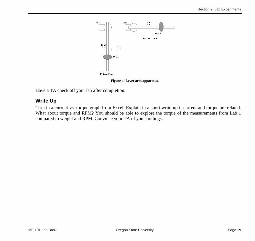
Attach a weight to your lever arm some distance away from the center of your motor and measure the current of your motor as the arm rotates from vertical to a horizontal position, Figure 4. Record the largest current. Move the weight to a different distance from the center of the motor and repeat, filling in Table 3. Be sure to have some measurements where the motor cannot quite raise the arm all the way to horizontal. Plot the torque vs. current curve using Excel.
Table 3: Data for current vs. torque measurements
Weight Distance Current Torque
Section 2: Lab Experiments
ME 101 Lab Book Oregon State University Page 19
Figure 4: Lever arm apparatus.
Have a TA check off your lab after completion.
Write Up Turn in a current vs. torque graph from Excel. Explain in a short write-up if current and torque are related. What about torque and RPM? You should be able to explore the torque of the measurements from Lab 1 compared to weight and RPM. Convince your TA of your findings.

Section 2: Lab Experiments
Page 20 Oregon State University ME 101 Lab Book
Simple Control System – Lab 3
Objective • Learn basic concepts of input/output systems • Thermal control
Prelab • This is a very tough lab. You should read ahead and start your design before coming to lab. If you don’t have a
soldering iron, work on the code as much as you can.
Procedure In this lab you will construct a simple cooling control system. The input for the system is from a thermistor that will be connected to a resistor across the motor terminals. A small computer fan will be connected to another motor terminal which will turn on once the resistor gets hot enough to try and cool it down.
Setup 1 Solder two 56Ω ½W (green, blue, black) resistors in parallel and attach to motor terminal 1. Then attach a small fan across motor terminal 2 (Note: if the fan is DC, the wires can only be inserted one way: the positive lead is on the forward side of the terminal, the side closer to the power terminal).
Figure 5: Attaching a resistor and fan to the motor outputs.
Assemble a thermistor sensor. Solder a thermistor in series with a 4.7KΩ 1/8W (yellow, violet, red) resistor, Figure 6. Then attach three wires as shown in Figure 7; these wires will need to be approximately 8-10 inches long.

Section 2: Lab Experiments
ME 101 Lab Book Oregon State University Page 21
Figure 6: A thermistor sensor.
Connect the power lead on the resistor to Vcc on terminal J10, the power lead on the thermistor to ground on terminal J11, and the signal lead to alternate input 1 on terminal J10. Using a small piece of tape, tape the thermistor to the resistor on the motor terminal.
Figure 7: Attaching the thermistor to the resistor.
Write a program that will continuously poll an input from the thermistor; then depending on the level given by the thermistor, decide when to turn the fan on or off to keep the resistor at a fairly cool temperature. In this program, motor output 1 is always on; this will heat up the resistor. As the resistor heats up, the number given by the ADC will go down. Write the program such that the resistor temperature will always be around 124. As a safety precaution, at 50 the resistor has become too hot; program the board such that everything will be shut off.
You are building a simple control system, Figure 8, that monitors the heat of the resistor. There is a lot of math behind what you are doing that can make your program more efficient, but you will have to wait to learn more

Section 2: Lab Experiments
Page 22 Oregon State University ME 101 Lab Book
about it.
Figure 8: Simple control system.
Feedback is often needed to determine if a product is functioning correctly. Send the output from the ADC to Hyper Terminal, and refer to Section 3 for help. Sending all the data is impractical; however, in your program, find a way to only display critical values or only when prompted by the user. When reading from the ADC, use the ‘read_adc’ function.
Setup 2 Most systems that require heat dissipation use a combination of a heat sink and a fan. Hook up the thermistor, Figure 9. The two resistors and thermistor will need to be soldered onto the heat sink. Run the program again and note the differences.
Figure 9: Heat sink and thermistor.

Section 2: Lab Experiments
ME 101 Lab Book Oregon State University Page 23
The new system you have built is slightly different than the first one. You have added a new ‘gain stage’ to your control system, Figure 10. The heat sink acts to amplify the cooling from the fan. Is your fan on more or less often with the heat sink attached?
Figure 10: New control system.
Write up Turn in the program you wrote for this lab. In this lab, you used two ways to reduce temperatures in a system; describe at least two other ways that temperature in systems can be controlled. How do these methods differ; is one better or cheaper? Discuss these and other aspects in your analysis. Discuss what could happen if the heat sink was infinitely large (over-dampened) or infinitely small (under-dampened).


Section 3 Board Experiments

Section 3: Board Experiments
Page 26 Oregon State University ME 101 Lab Book
Section Overview These experiments are intended to show some of the application possibilities of the Mechatronics board. The application examples are broken into groups based on which functionalities of the mx_ctlr.0 are used. The experiments progress from simple to more complex functionalities. All experiments will contain the required code, explanations, and hardware setup for each. The code for each experiment can be downloaded from mx_ctlr.0 website (Appendix B). Help on commands can also be found in the mech_lib documentation (Appendix B).
Soldering the Motors and Switches Included in the kit is a length of CAT 5 cable that will be used to solder the motors and switches. Cut off a section of the blue insulation, being careful not to cut the wires inside (after 10" of the insulation has been cut, the rest of the wires can be removed by pulling them out of the insulation). Cut a desired length of wire for the motors and strip about ¼" of the insulation off both ends, leaving a bare section of copper wire. Attach the wires as shown in Figure 11; this will help prevent the leads from breaking off of the motors. Solder the leads to the terminals on the motor as shown in Figure 12.
Figure 11: Stripping wires.

Section 3: Board Experiments
ME 101 Lab Book Oregon State University Page 27
Figure 12: Attaching wires to the motor.
The switches can be hooked up as normally open or normally closed switches. This means that they can be connected so that when the switch is not activated, the two wires are shorted together (normally closed) or not shorted (normally open). To make a normally open switch, connect one wire to the center terminal and the other wire to the terminal that is not connected to the center when the switch is not pressed. To make a normally closed switch, attach the center wire and the terminal that is connected to the center when the switch is not pressed.
Figure 13: Normally open switch (left), normally closed switch (right).
Once the motor and switches have been wired, they can be inserted into the board using the terminal blocks as shown in Figure 14. Screw the tops down to make a snug connection.

Section 3: Board Experiments
Page 28 Oregon State University ME 101 Lab Book
Figure 14: Attaching devices to the mx_ctlr board.

Section 3: Board Experiments
ME 101 Lab Book Oregon State University Page 29
Power Supply, ISP Connector, Reset Button
Basic Programming For this experiment, hook up two motors to motor terminals 1 and 2. Download the program for this experiment from the mx_ctlr website (Appendix B) and refer to section 1 on how to program the board. This program turns the motors forward and then reverse; once it has completed the cycle, the reset button must be pressed to start the sequence again. A program such as this is similar to what a VCR might do: once the tape has finished, the VCR would need to rewind it to play again.
Simple sequential control like this can create many different systems and unique devices. Most assembly lines and machines break down to this type of control.
/******************************************************************** This program runs all four motor output forward, then reverses two of them then stops all four motors. Once all four motors are stopped, the reset button must be pressed, or the power must be removed before the program will run again ********************************************************************/ /*all text that appears between /* and */ and after the // are comments and are ignored by the program*/ #include <mechlib.h> //This library contains the functions specific to the mechatronics board main() while(1) //this while loop is always true, it will continue forever forward(1); //this function turns the motor number inside the parentheses forward forward(2); forward(3); forward(4); delay(20); //this function delays the program from continuing for 2 seconds reverse(1); //this function puts the numbered motor in reverse reverse(3); delay(20); halt(); //this function stops all actions of the program //reset must be pushed to start over

Section 3: Board Experiments
Page 30 Oregon State University ME 101 Lab Book
Basic Inputs, Limit Switches, Motors
Motor Control This section will introduce the basic input terminals and how to use them with the limit switches. Attach a motor to motor terminal 1 and 2, and switches on inputs 1 and 2. Download the program for this section onto the board. This program uses the inputs from the switches to turn the motors forward until the switch is released. Programs similar to this might be used in control system for a car, as long as you turn the steering wheel, the car continues to turn. Another option is to have a system where you press a switch once to start an event, and then press it again to stop it. Many different types of control systems used some type of feedback to double-check what is occurring. Even machines that run through a timed sequence of events will have built in fail-safes that are always monitored to prevent injury to people.
Using limit switches is very important for many mechanical devices. As humans we have a lot of built in ‘position control’ sensors, we know where all of the parts of our body are at all times; machines don’t inherently have this ability, so it has to be designed in.
Let’s take a common computer printer for example. How does the printer know that the printer head is at the edge of the paper? In many printers there is a limit switch that the head presses when it is at the edge of the paper.
/******************************************************* This program turns on a motor while the corresponding switch is being pressed. *******************************************************/ #include <mechlib.h> main() while(1) while(poll_sensor(1)) //as long as switch one is on forward(1); //turn on motor one if(poll_sensor(2)) //if switch 1 and 2 are on forward(2); //turn on motors 1 and 2 coast(1); //turns off the motors when the coast(2); //switch is not pressed while(poll_sensor(2)) forward(2); if(poll_sensor(1)) forward(1); coast(1); coast(2);

Section 3: Board Experiments
ME 101 Lab Book Oregon State University Page 31
State Control Logic The program in this section uses state logic to control the motors. Depending on what state the motors are in, activating the input switch will have different output combinations. For this section, attach the motors to terminals 1 and 2 and a switch to input 1. When the switch is depressed the motors will change state. Similar systems are used when a series of outputs are needed from a single unit, such as an assembly line where the task will vary from lifting to attaching to moving.
A state controller like this one allows for a lot of different functionalities. Many different inputs could allow for lots of different outputs depending on what was going on with the machine at the time. For example, in a washing machine, it wouldn’t make any sense to add the fabric softener during the wash cycle.
Motor 1 Motor 2 Motor 1 – Next State
Motor 2 – Next State
Stop Stop Stop Forward
Stop Forward Forward Stop
Forward Stop Forward Forward
Forward Forward Stop Stop
/******************************************** This program turns on the motor outputs in a binary sequence when a switch is pressed ********************************************/ #include <mechlib.h> main() unsigned char state=0; while(1) if(poll_sensor(1)&&state==0) brake(1); forward(2); state=1; delay(3); if(poll_sensor(1)&&state==1) forward(1); brake(2); state=2; delay(3); if(poll_sensor(1)&&state==2) forward(1); forward(2); state=3; delay(3); if(poll_sensor(1)&&state==3) brake(1); brake(2); state=0; delay(3);

Section 3: Board Experiments
Page 32 Oregon State University ME 101 Lab Book
Digital Switches
Elevator Service For this experiment, an LED will need to be hooked up in series with a 100Ω resistor (brown, black, brown) with two leads attached.
Note: be careful to solder the shorter lead of the LED to the resistor; the LED has polarity and will not work if soldered on backward.
Figure 15: Attaching a LED.
Once the LED has been soldered, attach the lead on the LED without the resistor attached to Vcc on the alternate input port and the lead on the resistor not connected to the LED to digital switch 1. You will also need to attach three switches (inputs 1, 2 and 3). Motors are optional for this lab since the motor LEDs will indicate which motor is on and which direction it is going.
In a building with four elevators, in order to conserve power and be more efficient, only three elevators will be on for normal use. Each switch will turn on a motor terminal that represents an elevator. When two of the
/************************************************************************************* This program uses three switches to represent an elevator in use, as long as a switch is held down, it will turn that motor forward. When two of the switches are held down, a light will flash. If all three switches are held down, then the light will turn on, putting forth elevator into use. *************************************************************************************/ #include <mechlib.h> void run(void); //function prototype main() while(1) while(poll_sensor(1)||poll_sensor(2)||poll_sensor(3)) run(); //calls the function while( (poll_sensor(1)&&poll_sensor(2))|| (poll_sensor(2)&& poll_sensor(3)) || (poll_sensor(1)&&poll_sensor(3)) ) output_on(1); //turns LED on delay(3); output_off(1); //turns LED off delay(3); run(); while(poll_sensor(1)&&poll_sensor(2)&&poll_sensor(3)) output_on(1); forward(4); run(); coast(4); run(); void run (void) //this function checks to see which switch is pressed if(poll_sensor(1)) forward(1); else coast(1); if(poll_sensor(2)) forward(2); else coast(2); if(poll_sensor(3)) forward(3); else coast(3);

Section 3: Board Experiments
ME 101 Lab Book Oregon State University Page 33
elevators are being used an indicator light will start blinking. Once all three elevators are in use, the forth elevator will start automatically and the light will turn on, indicating that all four elevators are in use.
The digital switch could be used for many different applications. It is not powerful enough to run an electromagnet or a motor, but it can easily trigger a relay that could run nearly any size device you would want—even something like a light bulb in a house or a large siren.

Section 3: Board Experiments
Page 34 Oregon State University ME 101 Lab Book
Pulse Width Modulation
Motor Speed Depending on the task at hand, you will need to have different operating speeds. This program allows you to step through four different motor speeds as well as reverse, by pressing the limit switches. You will need to attach one motor and two switches. This is similar to manual gears in a car: you press one button and the motor will speed up to a certain point, press the other switch and the motor will slow down to a stop. The precision command allows you to vary the speed of the motor in forward and reverse with 255 bits of accuracy.
Pulse width modulation (PWM), is used to control many motors today. It works by rapidly turning the electricity off and on to the motor. The more often the electricity is off, the slower the motor will turn. This method is very efficient because little energy is wasted since all of the electricity goes through the motor.
Alternate Inputs, Analog to Digital Converter, Sensors
Light detecting Motor Solder a photo resistor and a 470Ω resistor (yellow, violet, brown) in series. Connect a wire to each end and to the middle of the resistor/photo resistor pair, Figure 16. Connect the lead connected only to the resistor to Vcc on the alternate input port. Connect the lead only connected to the photo resistor to the GND on the alternate input. Connect the center lead to alternate input 1.
/******************************************************* This program is similar to a car engine, pressing one switch will make it go faster, and pressing the other one will make it go slower, it also has a reverse state ******************************************************/ #include <mechlib.h> main() unsigned char number=0; unsigned char speed[6]=0,20,40,100,255,60; //array while(1) if(poll_sensor(1)&&number<4) precise(1,1,speed[number+=1]); delay(2); if(poll_sensor(2)&&number>0) precise(1,1,speed[number-=1]); delay(2); if(poll_sensor(2)&&number==0) precise(1,0,speed[5]); while(!poll_sensor(1)); coast(1); delay(2);

Section 3: Board Experiments
ME 101 Lab Book Oregon State University Page 35
Figure 16: Attaching a photo resistor.
Autonomous devices, such as some robots, need to have the ability to detect objects around them. One possible solution is having a light detector that will find the brightest point or could detect when a light is behind an object. This program will start turning a motor once a switch has been pressed. When the switch is pressed again, usually after one rotation the motor will stop and go back to the brightest point. When the switch is pressed the third time, the motor will begin searching again.
Simple Motor Positioning A Hall effect sensor can be used as a simple position sensor to measure the rotation of the motor. The Hall effect sensors supplied in the Mechatronics kit are ‘omni polar’ sensors. This means they can detect both the north and south poles of a magnetic field. To use one, simply supply it with Vcc and GND and monitor the output. Figure 17 shows a diagram of the hall effect sensor. Connect Vcc and GND to Vcc and GND on the alternate input port. Connect the Output pin to input 1 on the alternate input port. You can use the ‘poll_ir’ command to check the Hall effect sensor.
/*********************************************************************** This program uses a photoresistor to detect the brightest point in the surrounding area then points in that direction ***********************************************************************/ #include <mechlib.h> // Uses switch main() unsigned char max_light=0, temp_value=0, count=0, position=0; while(1) while (!poll_sensor(1)) ; delay(3); /*collects data on brightness*/ while (!poll_sensor(1)) precise(1,1,60); delay(1); brake(1); temp_value=read_adc(0); count++; /*saves the location of brightest point*/ if(temp_value > max_light && count>3) max_light=temp_value; position=count; delay(3); /*returns to brightest point*/ if (count>3) brake(1); temp_value=count-position; for(temp_value; temp_value--; temp_value>0) precise(1,0,60); delay(1); brake(1); count=0; max_light=0; temp_value=0; position=0;

Section 3: Board Experiments
Page 36 Oregon State University ME 101 Lab Book
Figure 17: The hall effect sensor
Tape a small magnet to the side of the disc on the motor. The sensor will need to be mounted such that the flat side of the sensor faces the magnet. The sensor must be placed fairly close to the magnet on the motor to work. The motor will turn until the magnet and the sensor are lined up together. If the sensor is then moved away, the motor will turn until the sensor is again located.
Serial Communication
Computer – Board: Motor Control Nearly every electronic device today is controlled by some sort of a computer. The built in serial communication on the mx_ctlr.0 allows you to connect the computer to the board using any serial connection program. Download the program and connect the board to the computer using an extension male to male DB9 cable to either Com Port 1 or 2.
On your computer click Start → Programs → Accessories → Communication → HyperTerminal. You will then be prompted to enter a name for the communication. Choose any name you like, select an icon, and press OK. Select the port that the board is connected to and press OK. Under bits per second select 9600, and under Stop bits choose 2, and then click OK. You are now ready to control your board.
/*********************************************** This program will position a motor. The motor will go forward until the magnet triggers the hall effect sensor. Then the motor is stopped. If the sensor is moved the motor will go foward until triggered again. ***********************************************/ #include <mechlib.h> main() while(1) precise(2,1,20); //If the motor doesn't stop, just slows down and if(poll_sensor(1)) //goes forward again, make 20 a lower intensity. if(poll_sensor(1)) //goes forward again, make 20 a lower intensity. brake(2); delay(1);

Section 3: Board Experiments
ME 101 Lab Book Oregon State University Page 37
Table 4: Commands for Serial Program
Forward Reverse
Motor 1 1 5
Motor 2 2 6
Motor 3 3 7
Motor 4 4 8
The program will print anything you type on the keyboard back onto the screen for hyper terminal except for the numbers 1-8, which will turn the motors on forward or reverse as described in Table 4.
You can add additional commands, such as stop, using other keys by finding their corresponding values in an ASCII table. This can also be expanded to other functions on the board besides the motor outputs.
Board – Computer: Simple Voltmeter The Mechatronics board can also be used to send data to the computer. This program uses the built-in ADCs on the mx_ctlr.0, allowing you to take voltage measurements up to 5V. To measure a higher voltage, make a voltage divider and change the program to accommodate for the difference. In the code shown, the positive input voltage will be taken from alternate input 0. For external voltage sources, connect GND on the alternate input port to the ground of the external source.
Hyper terminal will also need to be set up the same way as the previous experiment. The voltmeter works by reading a value from the ADC, which is based on a reference voltage, in this case 5V. Some calculations are performed, giving a corresponding output voltage that can be sent to the computer. Because of the simplicity
/************************************************************************* This program takes an input from the keyboard and performs a corresponding function on the mechatronics board. All case number correspond to standard ascii values for keys, i.e. 0->48, a->97. *************************************************************************/ #include <mechlib.h> #include <stdio.h> #include <mega8535.h> void USART_Init( void ); main() int number=0; USART_Init(); while(1) number=getchar(); putchar(number); /*similar to multiple if statements*/ switch(number) /*if number=48, then*/ case 48: coast(1); coast(2); coast(3); coast(4); break; case 49: forward(1); break; case 50: forward(2); break; case 51: forward(3); break; case 52: forward(4); break; case 53: reverse(1); break; case 54: reverse(2); break; case 55: reverse(3); break; case 56: reverse(4); break; default: break; delay(2); void USART_Init( void ) /* Set baud rate to 9600*/ UBRRH=0x00; UBRRL=0x67; /* Enable receiver and transmitter */ UCSRB=0b00011000; UCSRC=0b10001110; /* Set frame format: 8data, 2stop bit */

Section 3: Board Experiments
Page 38 Oregon State University ME 101 Lab Book
of this setup, the voltage may off by as much as .05V in the 0-5V range.
Innovative Projects
Bumpbot The mx_ctlr.0 board can be used for many different things; one of these is as a robotic base. All that needs to be done is to mount motors to a
/*********************************************** This program acts as a bumpbot, it will go until a sensor is activated, backup, turn away, and go on. Depending on how the motor are hooked up, the robot will behave differently. ***********************************************/ #include <mechlib.h> main() while(1) forward(1); forward(2); /*if sensor one is hit, it will backup, turn, and go on*/ if(poll_sensor(1)) reverse(1); reverse(2); delay(3); forward(1); delay(3); forward(2); delay(3); if(poll_sensor(2)) reverse(1); reverse(2); delay(3); forward(2); delay(3); forward(1); delay(3);
/*************************************************************** This program uses the built in ADC on the chip to make a simple voltmeter. A voltage reading is taken every time a switch is pressed. ****************************************************************/ #include <mega8535.h> #include <mechlib.h> #include <stdio.h> void USART_Init( void ); void USART_Transmit( int data ); main() int ones=0, tenths=0, hund=0, count=0; float number=0; USART_Init(); while(1) if(poll_sensor(1)) /*reads the adc 3 times for accuracy*/ for(count=0; count<3; count++) number=adc_precise(0); /*calculates the corresponding voltage*/ number=(number)*5/1023; /*converts the number to BCD*/ ones=number; tenths=(number-ones)*10; hund=number*10; hund=(number*10-hund)*10; /*sends the value to the computer putchar can also be used*/ USART_Transmit(ones+48); USART_Transmit(46); //decimal USART_Transmit(tenths+48); USART_Transmit(hund+48); USART_Transmit(10); //new line USART_Transmit(13); //carriage return delay(5); void USART_Init( void ) /* Set baud rate */ UBRRH=0x00; UBRRL=0x67; /* Enable receiver and transmitter */ /* Set frame format: 8data, 2stop bit */ UCSRB=0b00011000; UCSRC=0b10001110; void USART_Transmit( int data ) /* Wait for empty transmit buffer */ while ( !( UCSRA & (1<<5)) ) ; /* Put data into buffer, sends the data */ UDR = data;

Section 3: Board Experiments
ME 101 Lab Book Oregon State University Page 39
flat piece of material and attach wheels. The mx_ctlr.0 then controls these motors to maneuver the robot around. This simple robotic base is similar to the TekBots base used in the School of EECS at Oregon State University, and can compete along side them in the annual TekBots Triathlon.
For the bumpbot program to operate, two limit switches or other sensors will need to be mounted in front of the robot and connected to inputs 1 and 2. It will then roam around aimlessly until a sensor signals a hit, then back up, turn away, and continue forward. If motor 1 and sensor 1 are hooked up on the same side, the robot will backup and turn away from the object that hit the sensor. If the motors and switches are crossed, the robot will turn into the direction of the object.


Appendix A Hardware

Appendix A: Hardware
Page 42 Oregon State University ME 101 Lab Book
Inputs The mx_ctlr.0 board has several different types of inputs and outputs allowing for a wide range of functions and actions. The inputs for the board can be broken into three basic categories: basic inputs, alternate inputs, and the power connection for the board.
Basic Input Terminals The basic input terminals are used to sense simple voltage conditions of either on or off. This makes these inputs perfect for sensing switches. A switch is connected to the signal line and ground terminals; the mx_ctlr takes care of the rest. When the switch is ‘closed’ and a connection is made between the input and ground, the controller will detect this and be able to react to it. Figure 18 shows these inputs and how they are arranged.
Figure 18: Basic input port drawing.
It is very important that these connectors not be wired to a voltage supply. All that is needed is a switch between the two terminals.
Alternate Input Terminals The alternate input ports on the mx_ctlr allow connection of more advanced sensors to the board. Sensors that require power or return an analog signal can be connected here and the controller can read the values and use them to make decisions. The sensors used in the labs and experiments are an example of how these inputs can be used.

Appendix A: Hardware
ME 101 Lab Book Oregon State University Page 43
Both alternate inputs are in the same terminal block; power and ground are located nearby to ease connection to the outside world. Figure 19 shows the pin out for the alternate port and its location on the mx_ctlr.0.
Figure 19: Alternate input pin out and location.
Power Connector The power connection for the mx_ctlr.0 board is a simple two-terminal screw-type connector into which bare wire can be inserted to make an electrical connection to supply power. Caution should be taken to ensure that power is applied with the correct polarity or the controller can be damaged. Figure 20 shows the power connector pin out.
Figure 20: Battery terminal connection.

Appendix A: Hardware
Page 44 Oregon State University ME 101 Lab Book
Outputs The mx_ctlr.0 board has a variety of outputs used to control motion and general purpose electronics. The two categories of these outputs are motor control and digital switches.
Motor Terminals The mx_ctlr.0 board has four motor controllers on board, allowing for direction control and electronic braking of DC motors. The connectors are divided into two levels: high power and low power terminals. The high power terminals, motors 1 and 2, can supply 1.2 amps per motor in short bursts. The low power channels, motors 3 and 4, can supply up to 600 milliamps per channel in short bursts. Figure 21 shows the motor connections on the board.
Figure 21: Motor connectors on the mx_ctlr.0 board.
The pin out for the motor connectors is shown in, Figure 22. When the motor is traveling forward (green LED on), the current (conventional current flow) is flowing out of the terminal labeled ‘forward’ and into the terminal called ‘reverse.’ When the motor is in reverse (red LED on), the current flows in the opposite direction.

Appendix A: Hardware
ME 101 Lab Book Oregon State University Page 45
Figure 22: Motor connector pin out.
Digital Switch Terminals The digital switch inputs are used to control other electrical devices. The switch works by either being open or closed, allowing current to flow or not to flow. The digital switches can pass up to 800mA of current in pulses or 115mA continuously, so small to moderate electrical devices can be controlled this way. Figure 23 shows the pin outs and location of the digital switch terminals.
Figure 23: Digital switch pin outs and location.
ISP Connector To program the mx_ctlr.0 board, the programming dongle must be connected to the controller using the In Systems Programming (ISP) connector. This connector allows the PC to talk to the correct part of the board for downloading code, verifying programming, and checking fuse or lock bits. Figure 24 shows the ISP connector location and pin out.
Figure 24: ISP connector pin out and location.
Appendix A: Hardware
Page 46 Oregon State University ME 101 Lab Book
Reset Button The reset button is used to restart the mx_ctlr.0 and allow it to begin running the downloaded program from the beginning. It is important that this switch be protected and is not pressed unintentionally or the board will restart the program – possibly at an inconvenient time.
Power Supply The mx_ctlr.0 has built-in power regulation and protection. From the power connector, current flows first through the main power switch, allowing the board to be turned off, and then into the power supply circuitry. The power supply circuitry takes care of voltage regulation and protection. If the mx_ctlr.0 tries to draw more than 5 amps, an internal fuse will blow, preventing operation. This fuse can be reset by turning the board off and removing the source of the extra current draw. There is also a polarity protection diode that will prevent damage if the board is incorrectly supplied with voltage.
Limit Switches One of the basic sensing elements included in the Mechatronics kit is the switch. There are two different switches included in the kit: a lever style and a leaf style.
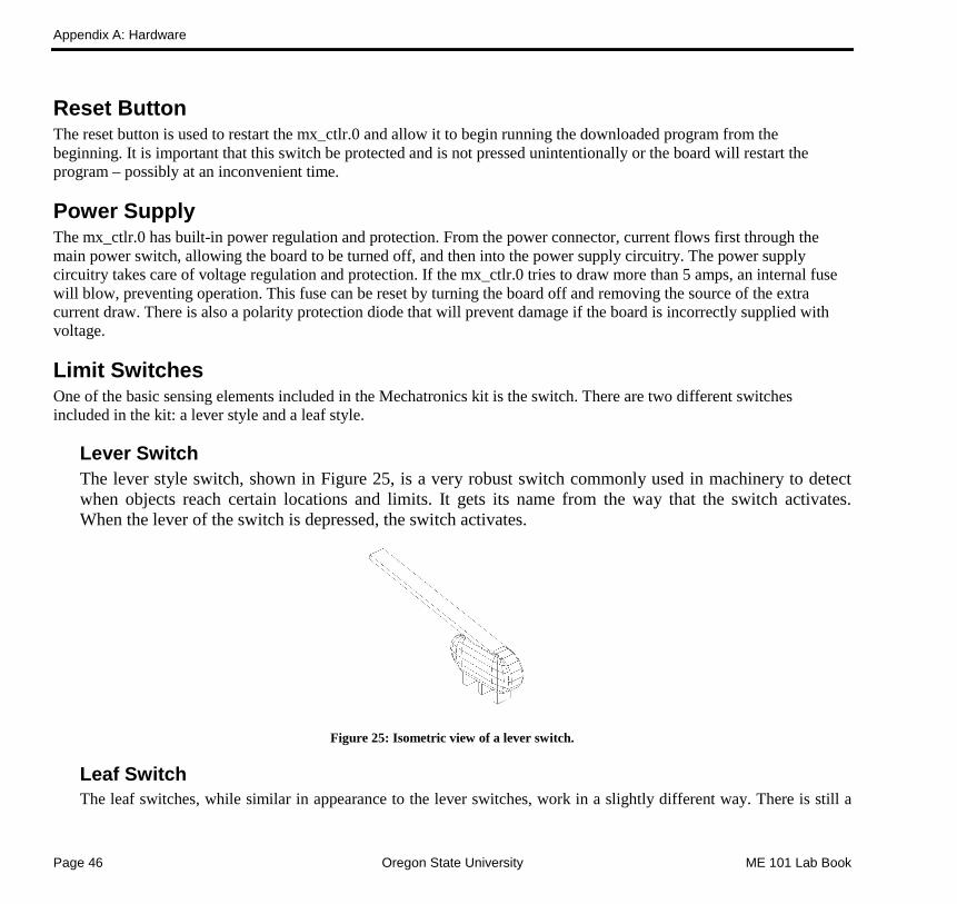
Lever Switch The lever style switch, shown in Figure 25, is a very robust switch commonly used in machinery to detect when objects reach certain locations and limits. It gets its name from the way that the switch activates. When the lever of the switch is depressed, the switch activates.
Figure 25: Isometric view of a lever switch.
Leaf Switch The leaf switches, while similar in appearance to the lever switches, work in a slightly different way. There is still a

Appendix A: Hardware
ME 101 Lab Book Oregon State University Page 47
lever arm that is activated, but the internal configuration of the ‘leaf springs’ in the switch make this a different switch type. Figure 26 shows a leaf switch.
Figure 26: Leaf switch.
Motors The motors included in the Mechatronics kit are DC gear motors. These motors use DC voltages to operate and are geared to supply more torque than a motor without gears, but with less speed. The gearboxes are made of a hard plastic that is rugged and resist corrosion.
To use a DC motor, a voltage needs to be applied across the two terminals of the motor. The voltage will cause current to flow that creates a magnetic field inside of the motor causing the motor to rotate If the voltage is reversed, current flows in the opposite direction, causing the motor to turn in the opposite direction. This is how the mx_ctlr.0 board makes the motors turn both forward and backward.
Serial Communication The mx_ctlr.0 board has built in serial communications. The board can talk to another mx_ctlr.0 board or a personal computer via the serial port at baud rates of up to 115 Kbps.
This can allow a PC to control the board or through another mx_ctlr.0. The high speed communications allow logging of what the controller does, relaying live information for processing on the PC, or using the computer to act as a remote control for the mx_ctlr.0.
Sensors
Hall Effect Hall effect sensors are used to detect magnetic fields. When a magnetic field is present and perpendicular to the current flow, in this case points into the sensor from the flat side, a Hall voltage is produced transversely to the current flow. When set up in accordance with this manual, the Hall effect sensor will produce an output of 3.5V normally and .02V with a magnetic field pointed at it. The sensors included in this kit are unidirectional and are only sensitive to the south side of a magnet. The Hall effect sensor can take a supply voltage between 3.5 - 24V and typically draws 2.5mA.

Appendix A: Hardware
Page 48 Oregon State University ME 101 Lab Book
Figure 27: Hall Effect sensor.
Photoresistors Photoresistor are a type of resistive element that can be used to detect the amount of light in a surrounding area. As the amount of light a photoresistor receives decreases, the more the resistance increases (resistance is high in the dark and low in the light). These particular sensors have a maximum resistance of 100KΩ.
Thermistors Thermistors are another type of resistive element that is sensitive to heat. As the thermistor gets hotter, the resistance decreases. This package type has a resistance of 6.8KΩ at 25˚C, and can operate in the range of -40˚- 125˚C.
Expansion Possibilities The mx_ctlr.0 board is designed to be easily upgradeable to include more features and functions with simple soldering or wiring. The following sections describe the upgrades as well as how they might be used.
IR Communication One of the most useful upgrades is the IR communications upgrade. This allows the mx_ctlr.0 board to communicate with other boards using infrared (IR) light. Any mx_ctlr.0 board equipped with the IR communications can communicate with as many other controller boards as can see the IR light, up to 10 feet away. The communications are limited to 2400 baud when using IR.
The IR communications might be used to control multiple mx_ctlr.0 boards. It can also be used to communicate through transparent surfaces.
Sensor Expandability The sensor inputs on the mx_ctlr.0 board are designed to be as generic as possible. This means that a wide

Appendix A: Hardware
ME 101 Lab Book Oregon State University Page 49
variety of sensors can be connected to the board and used to control the motors. For example, photoresistors can be connected to the alternate input to detect the amount of ambient light. Or connect tilt switches to the basic IO connectors, and the mx_ctlr.0 will be able detect when it is off balance.
Proto-Board Connections The mx_ctlr is designed so that if desired, an additional prototyping board can be easily attached to allow the user to build electrical systems and interface them to the mx_ctlr.0. The prototyping board attaches through the headers on the board, J15- J18, which are directly connected to the input/output pins on the microprocessor.
Troubleshooting
My board does not turn on Does the power LED turn on when applying power to the board? If it does not, check that the board is getting power from the batteries or power supply and that the switch is in the ‘on’ position. Are the batteries charged?
If the power LED does turn on, check to see if the code on the mx_ctlr.0 is correct. Does the code do anything that can be seen? Did it download correctly?
The power is on but nothing happens Once board power has been checked, the next step is to check that the code was properly downloaded into the mx_ctlr.0 board. CodeVision is the tool to be used for this. Refer to the Quick Start section of this document for assistance.
If code can be downloaded, then the mx_ctlr.0 board can be programmed successfully. If the board still is not working, then the problem may be with the downloaded code.
My board programs, but nothing happens If the board is programming and the board is still not functioning as expected, it is likely that the problem lies with the code is being downloaded. Download the test code found on the TekBots web site and download it to the board.
If the test code works, the problem lies with the other code. If it doesn’t work, check that it is downloading properly and that the power is on. If this does not fix the problem, contact technical support.

Appendix A: Hardware
Page 50 Oregon State University ME 101 Lab Book
Appendix B Installing CodeVision and the mech_lib

Appendix B: Installing CodeVision and the Mechlib
Page 52 Oregon State University ME 101 Lab Book
Mechlib is an open source library developed by the TekBots team at Oregon State University to aid users in programming an Atmel AVR microcontroller board. This library is released under the GPL; for source code, license info, and supporting materials please grab the tarball: mechlib-0.1.0.tar.gz.
To set up CodeVision AVR for the first time, follow the instructions below.
1. To get started with CodeVision AVR and mechlib, download the CodeVision Installer from http://eecs.oregonstate.edu/tekbots/mechlib_html/files/setup.exe. Run the executable. Agreeing to the default options will install CodeVision in c:\cvavre\; the rest of these instructions will assume this location.
2. To make the mechlib available to CodeVision, save mechlib.h and mega8535asm.h to c:\cvavr\inc\. Copy mechlib.lib to c:\cvavr\lib\. These three files can be found in the zip file at http://eecs.oregonstate.edu/tekbots/mechlib_html/files/mechlib.zip.
3. Here is a step by step example of creating a CodeVision project, and using mechlib functions to program the mx_ctlr.0 microcontroller board:
a. Switch the board off using the slide switch. Connect the 7.2V power supply or batteries to the power input marked with a “+” and “-.” Connect the small fitting on the programming dongle to the board. Connect the larger end of the programming dongle to your PC’s parallel port.
b. Turn the board on and confirm that the “on” light illuminates. Note that you may need to disconnect any motors if don’t want them running and moving around while you are programming the board. The following example should demonstrate everything you need to know to use CodeVision to compile a program and transmit that program to your board. Start CodeVision and create a new project (File → New → Project → OK). Use the code generation wizard: a tabbed interface with many options should be displayed. For our purposes, you can ignore most of this and simply choose the chip type as “ATmega8535” with a clock speed of 16MHz. Choose File → Generate Save and Exit. Change to the directory where you want to save your programming, then enter the name “example” and hit “OK” each time you are prompted.
c. You should now be looking at an editor window with a lot of C code (this is the example.c file that you created). Click anywhere in this editor window and then press CTRL-A, BACKSPACE this will delete all the code generated by CodeVision. Go to the mechlib website and choose the “forward” link from the menu on the left. After the description of the forward function, there are two examples. Copy and paste the second example in to the CodeVision editor window; don’t include the word “Example” when you copy the code. Set up the programmer: Settings → Programmer → Kanda Systems (from drop down menu). Change the CodeVision setting that will allow you to compile your code and program the board at the same time: choose Project → Configure → After Make → program the chip → OK. Now press SHIFT-F9 to compile the code and program your board. After a few seconds, the board should begin running motors 1 and 3, and then motors 2 and 4, alternating every second. You can verify this function by watching for the green lights next to the motor outputs.

Appendix B: Installing CodeVision and the Mechlib
ME 101 Lab Book Oregon State University Page 53
You can check for new versions of CodeVision at HP Info Tech.
Useful Links
Programs CodeVisionAVR Library Functions http://eecs.oregonstate.edu/tekbots/mechlib_html/
Board Experiment Programs Basic Programming Basic Motor Control Motor Control Logic Elevator Service Motor Speed Light Detecting Motor Simple Tachometer Computer – Board: Motor Control Board – Computer: Voltmeter Bumpbot http://eecs.oregonstate.edu/tekbots/mx_ctlr.0/code_samples/
Mechlib Library Mech_lib: http://eecs.oregonstate.edu/tekbots/mechlib_html/


Appendix C Parts List

Appendix C: Parts List
Page 56 Oregon State University ME 101 Lab Book
Qty Description 1 mx_ctlr.0 controller board 2 GM-2 geared DC motors 3 Leaf switch 1 Lever switch 5' CAT-5 wire 1 10 programming cable 1 avr-isp programming dongle 2 Resistor – 56Ω ½W 1 Resistor – 100Ω ½W 1 Resistor – 100Ω 1 Resistor – 470Ω 1 Resistor – 1.2KΩ 1 Thermistor – 6.8KΩ 1 Photo-Resistor – 100KΩ 1 Hall effect sensor - Unidirectional 1 Heat sink 1 DC fan 2 LED – red 1 Female header – 1x2 1 Female header – 1x4

Appendix D Schematic

Appendix D: Schematic
Page 58 Oregon State University ME 101 Lab Book

Appendix E Parts Suppliers

Appendix E: Parts Suppliers
Page 60 Oregon State University ME 101 Lab Book
DigiKey 701 Brooks Ave. South
Thief River Falls, MN 56701-0677 (800) 344-4539
Mouser Electronics 1000 N. Main Street Mansfield, TX 76063 (800) 346-6873
Allied Electronics 6700 SW 105th St, Suite 106 Beaverton, OR 97008 (800) 433-5700
TekBots 220 Owen Hall Oregon State University Corvallis, OR 97331 [email protected]
Jameco Electronics 1355 Shoreway Rd Belmont, CA 94002 (800) 831-4242