copyright © 2009 pearson education, inc. chapter 31 maxwell’s equations and electromagnetic waves
TRANSCRIPT

Copyright © 2009 Pearson Education, Inc.
Chapter 31Maxwell’s Equations and Electromagnetic Waves

Copyright © 2009 Pearson Education, Inc.
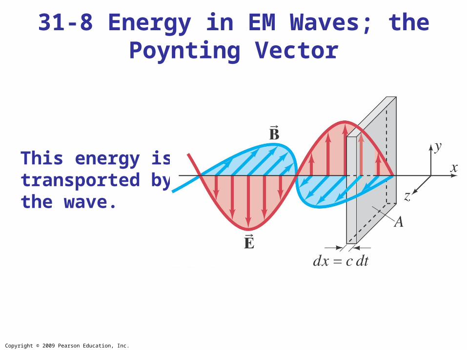
Energy is stored in both electric and magnetic fields, giving the total energy density of an electromagnetic wave:
Each field contributes half the total energy density:
31-8 Energy in EM Waves; the Poynting Vector
Copyright © 2009 Pearson Education, Inc.
This energy is transported by the wave.
31-8 Energy in EM Waves; the Poynting Vector

Copyright © 2009 Pearson Education, Inc.
The energy transported through a unit area per unit time is called the intensity:
31-8 Energy in EM Waves; the Poynting Vector
Its vector form is the Poynting vector:

Copyright © 2009 Pearson Education, Inc.
31-8 Energy in EM Waves; the Poynting Vector
Typically we are interested in the average value of S:S
.
Copyright © 2009 Pearson Education, Inc.
31-8 Energy in EM Waves; the Poynting Vector
Example 31-6: E and B from the Sun.
Radiation from the Sun reaches the Earth (above the atmosphere) at a rate of about 1350 J/s·m2 (= 1350 W/m2). Assume that this is a single EM wave, and calculate the maximum values of E and B.

Copyright © 2009 Pearson Education, Inc.
In addition to carrying energy, electromagnetic waves also carry momentum. This means that a force will be exerted by the wave.
The radiation pressure is related to the average intensity. It is a minimum if the wave is fully absorbed:
and a maximum if it is fully reflected:
31-9 Radiation Pressure

Copyright © 2009 Pearson Education, Inc.
31-9 Radiation Pressure
Example 31-7: Solar pressure.
Radiation from the Sun that reaches the Earth’s surface (after passing through the atmosphere) transports energy at a rate of about 1000 W/m2. Estimate the pressure and force exerted by the Sun on your outstretched hand.

Copyright © 2009 Pearson Education, Inc.
31-9 Radiation Pressure
Example 31-8: A solar sail.
Proposals have been made to use the radiation pressure from the Sun to help propel spacecraft around the solar system. (a) About how much force would be applied on a 1 km x 1 km highly reflective sail, and (b) by how much would this increase the speed of a 5000-kg spacecraft in one year? (c) If the spacecraft started from rest, about how far would it travel in a year?

Copyright © 2009 Pearson Education, Inc.
• Maxwell’s equations are the basic equations of electromagnetism:
Summary of Chapter 31

Copyright © 2009 Pearson Education, Inc.
• Electromagnetic waves are produced by accelerating charges; the propagation speed is given by
• The fields are perpendicular to each other and to the direction of propagation.
Summary of Chapter 31

Copyright © 2009 Pearson Education, Inc.
• The wavelength and frequency of EM waves are related:
• The electromagnetic spectrum includes all wavelengths, from radio waves through visible light to gamma rays.
• The Poynting vector describes the energy carried by EM waves:
Summary of Chapter 31

Copyright © 2009 Pearson Education, Inc.
Chapter 32Light: Reflection and
Refraction

Copyright © 2009 Pearson Education, Inc.
• The Ray Model of Light
• Reflection; Image Formation by a Plane Mirror
• Formation of Images by Spherical Mirrors
• Index of Refraction
• Refraction: Snell’s Law
Units of Chapter 32
Copyright © 2009 Pearson Education, Inc.
• Visible Spectrum and Dispersion
• Total Internal Reflection; Fiber Optics
• Refraction at a Spherical Surface
Units of Chapter 32

Copyright © 2009 Pearson Education, Inc.
Light very often travels in straight lines. We represent light using rays, which are straight lines emanating from an object. This is an idealization, but is very useful for geometric optics.
32-1 The Ray Model of Light

Copyright © 2009 Pearson Education, Inc.
Law of reflection: the angle of reflection (that the ray makes with the normal to a surface) equals the angle of incidence.
32-2 Reflection; Image Formation by a Plane Mirror

Copyright © 2009 Pearson Education, Inc.
When light reflects from a rough surface, the law of reflection still holds, but the angle of incidence varies. This is called diffuse reflection.
32-2 Reflection; Image Formation by a Plane Mirror

Copyright © 2009 Pearson Education, Inc.
With diffuse reflection, your eye sees reflected light at all angles. With specular reflection (from a mirror), your eye must be in the correct position.
32-2 Reflection; Image Formation by a Plane Mirror

Copyright © 2009 Pearson Education, Inc.
32-2 Reflection; Image Formation by a Plane Mirror
Example 32-1: Reflection from flat mirrors.
Two flat mirrors are perpendicular to each other. An incoming beam of light makes an angle of 15° with the first mirror as shown. What angle will the outgoing beam make with the second mirror?

Copyright © 2009 Pearson Education, Inc.
What you see when you look into a plane (flat) mirror is an image, which appears to be behind the mirror.
32-2 Reflection; Image Formation by a Plane Mirror

Copyright © 2009 Pearson Education, Inc.
This is called a virtual image, as the light does not go through it. The distance of the image from the mirror is equal to the distance of the object from the mirror.
32-2 Reflection; Image Formation by a Plane Mirror

Copyright © 2009 Pearson Education, Inc.
32-2 Reflection; Image Formation by a Plane Mirror
Example 32-2: How tall must a full-length mirror be?
A woman 1.60 m tall stands in front of a vertical plane mirror. What is the minimum height of the mirror, and how close must its lower edge be to the floor, if she is to be able to see her whole body? Assume her eyes are 10 cm below the top of her head.

Copyright © 2009 Pearson Education, Inc.
32-2 Reflection; Image Formation by a Plane Mirror
Conceptual Example 32-3: Is the photo upside down?
Close examination of the photograph on the first page of this Chapter reveals that in the top portion, the image of the Sun is seen clearly, whereas in the lower portion, the image of the Sun is partially blocked by the tree branches. Show why the reflection is not the same as the real scene by drawing a sketch of this situation, showing the Sun, the camera, the branch, and two rays going from the Sun to the camera (one direct and one reflected). Is the photograph right side up?
Copyright © 2009 Pearson Education, Inc.
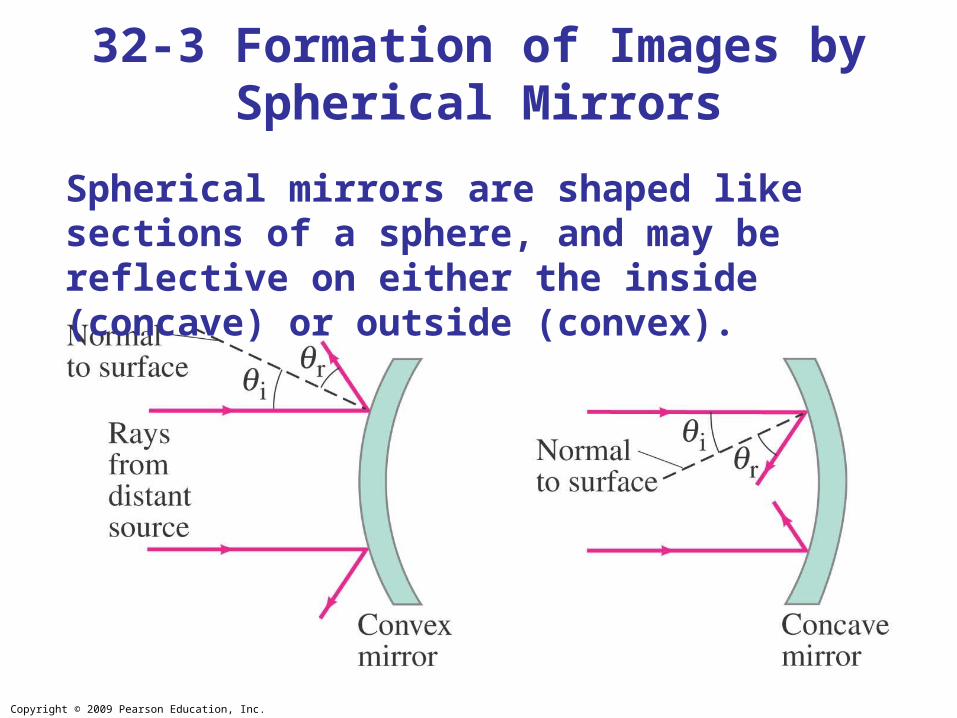
Spherical mirrors are shaped like sections of a sphere, and may be reflective on either the inside (concave) or outside (convex).
32-3 Formation of Images by Spherical Mirrors

Copyright © 2009 Pearson Education, Inc.
Rays coming from a faraway object are effectively parallel.
32-3 Formation of Images by Spherical Mirrors

Copyright © 2009 Pearson Education, Inc.
Parallel rays striking a spherical mirror do not all converge at exactly the same place if the curvature of the mirror is large; this is called spherical aberration.
32-3 Formation of Images by Spherical Mirrors

Copyright © 2009 Pearson Education, Inc.
If the curvature is small, the focus is much more precise; the focal point is where the rays converge.
32-3 Formation of Images by Spherical Mirrors

Copyright © 2009 Pearson Education, Inc.
Using geometry, we find that the focal length is half the radius of curvature:
Spherical aberration can be avoided by using a parabolic reflector; these are more difficult and expensive to make, and so are used only when necessary, such as in research telescopes.
32-3 Formation of Images by Spherical Mirrors

Copyright © 2009 Pearson Education, Inc.
We use ray diagrams to determine where an image will be. For mirrors, we use three key rays, all of which begin on the object:
1. A ray parallel to the axis; after reflection it passes through the focal point.
2. A ray through the focal point; after reflection it is parallel to the axis.
3. A ray perpendicular to the mirror; it reflects back on itself.
32-3 Formation of Images by Spherical Mirrors

Copyright © 2009 Pearson Education, Inc.
32-3 Formation of Images by Spherical Mirrors

Copyright © 2009 Pearson Education, Inc.
The intersection of these three rays gives the position of the image of that point on the object. To get a full image, we can do the same with other points (two points suffice for may purposes).
32-3 Formation of Images by Spherical Mirrors

Copyright © 2009 Pearson Education, Inc.
Geometrically, we can derive an equation that relates the object distance, image distance, and focal length of the mirror:
32-3 Formation of Images by Spherical Mirrors

Copyright © 2009 Pearson Education, Inc.
We can also find the magnification (ratio of image height to object height):
The negative sign indicates that the image is inverted. This object is between the center of curvature and the focal point, and its image is larger, inverted, and real.
32-3 Formation of Images by Spherical Mirrors

Copyright © 2009 Pearson Education, Inc.
32-3 Formation of Images by Spherical Mirrors
Example 32-4: Image in a concave mirror.
A 1.50-cm-high diamond ring is placed 20.0 cm from a concave mirror with radius of curvature 30.0 cm. Determine (a) the position of the image, and (b) its size.

Copyright © 2009 Pearson Education, Inc.
32-3 Formation of Images by Spherical Mirrors
Conceptual Example 32-5: Reversible rays.
If the object in this figure is placed where the image is, where will the new image be?
Figure 32-16 goes here.

Copyright © 2009 Pearson Education, Inc.
If an object is outside the center of curvature of a concave mirror, its image will be inverted, smaller, and real.
32-3 Formation of Images by Spherical Mirrors

Copyright © 2009 Pearson Education, Inc.
32-3 Formation of Images by Spherical Mirrors
Example 32-6: Object closer to concave mirror.
A 1.00-cm-high object is placed 10.0 cm from a concave mirror whose radius of curvature is 30.0 cm. (a) Draw a ray diagram to locate (approximately) the position of the image. (b) Determine the position of the image and the magnification analytically.

Copyright © 2009 Pearson Education, Inc.
For a convex mirror, the image is always virtual, upright, and smaller.
32-3 Formation of Images by Spherical Mirrors

Copyright © 2009 Pearson Education, Inc.
Problem Solving: Spherical Mirrors
1. Draw a ray diagram; the image is where the rays intersect.
2. Apply the mirror and magnification equations.
3. Sign conventions: if the object, image, or focal point is on the reflective side of the mirror, its distance is positive, and negative otherwise. Magnification is positive if image is upright, negative otherwise.
4. Check that your solution agrees with the ray diagram.
32-3 Formation of Images by Spherical Mirrors

Copyright © 2009 Pearson Education, Inc.
32-3 Formation of Images by Spherical Mirrors
Example 32-7: Convex rearview mirror.
An external rearview car mirror is convex with a radius of curvature of 16.0 m. Determine the location of the image and its magnification for an object 10.0 m from the mirror.

Copyright © 2009 Pearson Education, Inc.

Copyright © 2009 Pearson Education, Inc.
In general, light slows somewhat when traveling through a medium. The index of refraction of the medium is the ratio of the speed of light in vacuum to the speed of light in the medium:
32-4 Index of Refraction

Copyright © 2009 Pearson Education, Inc.
Light changes direction when crossing a boundary from one medium to another. This is called refraction, and the angle the outgoing ray makes with the normal is called the angle of refraction.
32-5 Refraction: Snell’s Law

Copyright © 2009 Pearson Education, Inc.
Refraction is what makes objects half-submerged in water look odd.
32-5 Refraction: Snell’s Law

Copyright © 2009 Pearson Education, Inc.
The angle of refraction depends on the indices of refraction, and is given by Snell’s law:
32-5 Refraction: Snell’s Law
Copyright © 2009 Pearson Education, Inc.
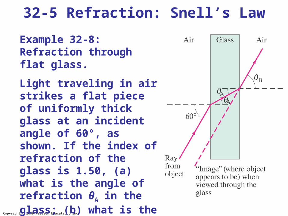
32-5 Refraction: Snell’s Law
Example 32-8: Refraction through flat glass.
Light traveling in air strikes a flat piece of uniformly thick glass at an incident angle of 60°, as shown. If the index of refraction of the glass is 1.50, (a) what is the angle of refraction θA in the glass; (b) what is the angle θB at which the ray emerges from the glass?

Copyright © 2009 Pearson Education, Inc.
32-5 Refraction: Snell’s Law
Example 32-9: Apparent depth of a pool.
A swimmer has dropped her goggles to the bottom of a pool at the shallow end, marked as 1.0 m deep. But the goggles don’t look that deep. Why? How deep do the goggles appear to be when you look straight down into the water?

Copyright © 2009 Pearson Education, Inc.
32-6 Visible Spectrum and Dispersion
The visible spectrum contains the full range of wavelengths of light that are visible to the human eye.

Copyright © 2009 Pearson Education, Inc.
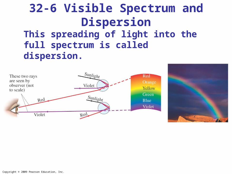
32-6 Visible Spectrum and Dispersion
The index of refraction of many transparent materials, such as glass and water, varies slightly with wavelength. This is how prisms and water droplets create rainbows from sunlight.
Copyright © 2009 Pearson Education, Inc.
32-6 Visible Spectrum and Dispersion
This spreading of light into the full spectrum is called dispersion.

Copyright © 2009 Pearson Education, Inc.
32-6 Visible Spectrum and Dispersion
Conceptual Example 32-10: Observed color of light under water.
We said that color depends on wavelength. For example, for an object emitting 650 nm light in air, we see red. But this is true only in air. If we observe this same object when under water, it still looks red. But the wavelength in water λn is 650 nm/1.33 = 489 nm. Light with wavelength 489 nm would appear blue in air. Can you explain why the light appears red rather than blue when observed under water?

Copyright © 2009 Pearson Education, Inc.
If light passes into a medium with a smaller index of refraction, the angle of refraction is larger. There is an angle of incidence for which the angle of refraction will be 90°; this is called the critical angle:
32-7 Total Internal Reflection; Fiber Optics

Copyright © 2009 Pearson Education, Inc.
If the angle of incidence is larger than this, no transmission occurs. This is called total internal reflection.
32-7 Total Internal Reflection; Fiber Optics

Copyright © 2009 Pearson Education, Inc.
32-7 Total Internal Reflection; Fiber Optics
Conceptual Example 32-11: View up from under water.
Describe what a person would see who looked up at the world from beneath the perfectly smooth surface of a lake or swimming pool.

Copyright © 2009 Pearson Education, Inc.
Binoculars often use total internal reflection; this gives true 100% reflection, which even the best mirror cannot do.
32-7 Total Internal Reflection; Fiber Optics

Copyright © 2009 Pearson Education, Inc.
32-7 Total Internal Reflection; Fiber Optics
Optical fibers also depend on total internal reflection; they are therefore able to transmit light signals with very small losses.

Copyright © 2009 Pearson Education, Inc.
32-8 Refraction at a Spherical Surface
Rays from a single point will be focused by a convex spherical interface with a medium of larger index of refraction to a single point, as long as the angles are not too large.

Copyright © 2009 Pearson Education, Inc.
32-8 Refraction at a Spherical Surface
Geometry gives the relationship between the indices of refraction, the object distance, the image distance, and the radius of curvature:

Copyright © 2009 Pearson Education, Inc.
32-8 Refraction at a Spherical Surface
For a concave spherical interface, the rays will diverge from a virtual image.

Copyright © 2009 Pearson Education, Inc.
32-8 Refraction at a Spherical Surface
Example 32-12: Apparent depth II.
A person looks vertically down into a 1.0-m-deep pool. How deep does the water appear to be?

Copyright © 2009 Pearson Education, Inc.
32-8 Refraction at a Spherical Surface
Example 32-13: A spherical “lens.”
A point source of light is placed at a distance of 25.0 cm from the center of a glass sphere of radius 10.0 cm. Find the image of the source.

Copyright © 2009 Pearson Education, Inc.
• Light paths are called rays.
• Index of refraction:
• Angle of reflection equals angle of incidence.
• Plane mirror: image is virtual, upright, and the same size as the object.
• Spherical mirror can be concave or convex.
• Focal length of the mirror:
Summary of Chapter 32

Copyright © 2009 Pearson Education, Inc.
• Mirror equation:
• Magnification:
• Real image: light passes through it.
• Virtual image: light does not pass through.
Summary of Chapter 32

Copyright © 2009 Pearson Education, Inc.
• Law of refraction (Snell’s law):
• Total internal reflection occurs when angle of incidence is greater than critical angle:
Summary of Chapter 32