copyright 2016 aia masterspec premium 03/16 product ... · pdf filehydronic piping 232113 - 1...
TRANSCRIPT
Copyright 2016 AIA MasterSpec Premium 03/16
PRODUCT MASTERSPEC LICENSED BY ARCOM TO MUELLER INDUSTRIES, INC.
HYDRONIC PIPING 232113 - 1
This Product MasterSpec Section is licensed by ARCOM to Mueller Industries, Inc. ("Licensee").
This Product MasterSpec Section modifies the original MasterSpec text, and does not include the
full content of the original MasterSpec Section.
Revisions made to the original MasterSpec text are made solely by the Licensee and are not endorsed by,
or representative of the opinions of, ARCOM or The American Institute of Architects (AIA). Neither
AIA nor ARCOM are liable in any way for such revisions or for the use of this Product MasterSpec
Section by any end user. A qualified design professional should review and edit the document to suit
project requirements.
For more information, contact Mueller Streamline Co., 8285 Tournament Drive, Memphis, TN 38125;
Phone: 800-846-9750; Website: www.muellerindustries.com; Email: [email protected].
For information about MasterSpec contact ARCOM at (800) 424-5080 or visit www.MasterSpec.com.
SECTION 232113 - HYDRONIC PIPING
TIPS:
To view non-printing Editor's Notes that provide guidance for editing, click on MasterWorks/Single-File
Formatting/Toggle/Editor's Notes.
To read detailed research, technical information about products and materials, and coordination
checklists, click on MasterWorks/Supporting Information.
PART 1 - GENERAL
1.1 RELATED DOCUMENTS
A. Drawings and general provisions of the Contract, including General and Supplementary
Conditions and Division 01 Specification Sections, apply to this Section.
1.2 SUMMARY
A. Section includes pipe and fitting materials and joining methods for the following:
1. Copper tube and fittings.
2. Steel pipe and fittings.
3. Plastic pipe and fittings.
4. Fiberglass pipe and fittings.
5. Joining materials.
6. Transition fittings.
7. Dielectric fittings.
8. Bypass chemical feeder.
Copyright 2016 AIA MasterSpec Premium 03/16
PRODUCT MASTERSPEC LICENSED BY ARCOM TO MUELLER INDUSTRIES, INC.
HYDRONIC PIPING 232113 - 2
1.3 ACTION SUBMITTALS
A. Product Data: For each type of the following:
1. Pipe.
2. Fittings.
3. Joining materials.
4. Bypass chemical feeder.
B. Sustainable Design Submittals:
1. Product Data: For adhesives, indicating VOC content.
2. Laboratory Test Reports: For adhesives, indicating compliance with requirements for
low-emitting materials.
C. Delegated-Design Submittal:
1. Design calculations and detailed fabrication and assembly of pipe anchors and alignment
guides, hangers and supports for multiple pipes, expansion joints and loops, and
attachments of the same to the building structure.
2. Locations of pipe anchors and alignment guides and expansion joints and loops.
3. Locations of and details for penetrations, including sleeves and sleeve seals for exterior
walls, floors, basement, and foundation walls.
4. Locations of and details for penetration and firestopping for fire- and smoke-rated wall
and floor and ceiling assemblies.
1.4 INFORMATIONAL SUBMITTALS
A. Coordination Drawings: Piping layout, drawn to scale, on which the following items are shown
and coordinated with each other, using input from installers of the items involved:
1. Suspended ceiling components.
2. Other building services.
3. Structural members.
B. Qualification Data: For Installer.
C. Welding certificates.
D. Field quality-control reports.
E. Preconstruction Test Reports:
1. Water Analysis: Submit a copy of the water analysis to illustrate water quality available
at Project site.
1.5 QUALITY ASSURANCE
A. Installer Qualifications:
Copyright 2016 AIA MasterSpec Premium 03/16
PRODUCT MASTERSPEC LICENSED BY ARCOM TO MUELLER INDUSTRIES, INC.
HYDRONIC PIPING 232113 - 3
1. Installers of Pressure-Sealed Joints: Installers shall be certified by pressure-seal joint
manufacturer as having been trained and qualified to join piping with pressure-seal pipe
couplings and fittings.
2. Fiberglass Pipe and Fitting Installers: Installers of RTRF and RTRP shall be certified by
manufacturer of pipes and fittings as having been trained and qualified to join fiberglass
piping with manufacturer-recommended adhesive.
B. Steel Support Welding: Qualify procedures and personnel according to AWS D1.1/D1.1M,
"Structural Welding Code - Steel."
C. Pipe Welding: Qualify procedures and operators according to ASME Boiler and Pressure Vessel
Code: Section IX.
1. Comply with ASME B31.9, "Building Services Piping," for materials, products, and
installation.
2. Certify that each welder has passed AWS qualification tests for welding processes
involved and that certification is current.
1.6 PRECONSTRUCTION TESTING
A. Preconstruction Testing Service: [Owner will engage] [Engage] a qualified testing agency to
perform preconstruction testing on water quality.
PART 2 - PRODUCTS
2.1 PERFORMANCE REQUIREMENTS
A. Hydronic piping components and installation shall be capable of withstanding the following
minimum working pressure and temperature unless otherwise indicated:
1. Hot-Water Heating Piping: [100 psig (689 kPa)] <Insert psig (kPa)> at [200 deg F (93
deg C)] [180 deg F (82 deg C)] <Insert temperature>.
2. Chilled-Water Piping: [150 psig (1034 kPa)] <Insert psig (kPa)> at [73 deg F (22
deg C)] <Insert temperature>.
3. Dual-Temperature Heating and Cooling Water Piping: [100 psig (1034 kPa)] <Insert
psig (kPa)> at [180 deg F (82 deg C)] <Insert temperature>.
4. Condenser-Water Piping: [150 psig (1034 kPa)] <Insert psig (kPa)> at [73 deg F (66
deg C)] <Insert temperature>.
5. Glycol Cooling-Water Piping: [150 psig (1034 kPa)] <Insert psig (kPa)> at [150 deg F
(66 deg C)] <Insert temperature>.
6. Makeup-Water Piping: [80 psig (552 kPa)] [150 psig (1034 kPa)] <Insert value> at [73
deg F (22 deg C)] [150 deg F (66 deg C)] <Insert temperature>.
7. Condensate-Drain Piping: [150 deg F (66 deg C)] [180 deg F (82 deg C)] <Insert
temperature>.
8. Blowdown-Drain Piping: [180 deg F (82 deg C)] [200 deg F (93 deg C)] <Insert
temperature>.
9. Air-Vent Piping: [180 deg F (82 deg C)] [200 deg F (93 deg C)] <Insert temperature>.
Copyright 2016 AIA MasterSpec Premium 03/16
PRODUCT MASTERSPEC LICENSED BY ARCOM TO MUELLER INDUSTRIES, INC.
HYDRONIC PIPING 232113 - 4
10. Safety-Valve-Inlet and -Outlet Piping: Equal to the pressure of the piping system to
which it is attached.
2.2 COPPER TUBE AND FITTINGS
A. Drawn-Temper Copper Tubing: [ASTM B 88, Type L (ASTM B 88M, Type B)]
[ASTM B 88, Type M (ASTM B 88M, Type C)].
B. Annealed-Temper Copper Tubing: ASTM B 88, Type K (ASTM B 88M, Type A).
C. DWV Copper Tubing: ASTM B 306, Type DWV.
D. Grooved, Mechanical-Joint, Wrought-Copper Fittings: ASME B16.22.
1. Manufacturers: Subject to compliance with requirements, provide products by one of the
following:
a. Anvil International.
b. Star Pipe Products.
c. Victaulic Company.
d. <Insert manufacturer's name>.
2. Grooved-End Copper Fittings: ASTM B 75 (ASTM B 75M), copper tube or
ASTM B 584, bronze casting.
3. Grooved-End-Tube Couplings: Rigid pattern unless otherwise indicated; gasketed fitting.
Ductile-iron housing with keys matching pipe and fitting grooves,[ prelubricated]
EPDM gasket rated for minimum 230 deg F (110 deg C) for use with housing, and steel
bolts and nuts.
E. Copper or Bronze Pressure-Seal Fittings: ASME B16.51, copper press-connect pressure fittings.
1. Hard-drawn Copper Tube: [ASTM B 88, Type K (ASTM B 88M, Type A)] [and]
[ASTM B 88, Type L (ASTM B 88M, Type B)] [and] [ASTM B 88, Type M
(ASTM B 88M, Type C)].
a. Basis-of-Design Product: Subject to compliance with requirements, provide
Mueller Industries, Inc. Streamline PRS™ copper press fittings or a comparable
product by one of the following:
1) Elkhart Products Corporation.
2) Viega LLC.
3) <Insert manufacturer's name>.
b. Fittings for NPS 2 (DN 50) and Smaller: Wrought-copper or bronze fitting with
EPDM-rubber O-ring seal in each end.
c. Fittings for NPS 2-1/2 to NPS 4 (DN 65 to DN 100): Wrought-copper or bronze
fitting with stainless-steel grip ring and EPDM-rubber O-ring seal in each end.
2. Soft Copper Tube: [ASTM B 88, Type K (ASTM B 88M, Type A)], water tube,
annealed temper.
Copyright 2016 AIA MasterSpec Premium 03/16
PRODUCT MASTERSPEC LICENSED BY ARCOM TO MUELLER INDUSTRIES, INC.
HYDRONIC PIPING 232113 - 5
a. Basis-of-Design Product: Subject to compliance with requirements, provide
Mueller Industries, Inc. Streamline PRS™ copper press fittings or a comparable
product by one of the following:
1) Elkhart Products Corporation.
2) Viega LLC.
3) <Insert manufacturer's name>.
b. Fittings for NPS 1-1/4 (DN 32) and Smaller: Wrought-copper or bronze fitting
with EPDM-rubber O-ring seal in each end.
F. Copper, Mechanically Formed Tee Option: For forming T-branch on copper water tube.
1. Manufacturers: Subject to compliance with requirements, provide products by one of the
following:
a. T-DRILL Industries Inc.
b. <Insert manufacturer's name>.
G. Wrought-Copper Unions: ASME B16.22.
2.3 STEEL PIPE AND FITTINGS
A. Steel Pipe: ASTM A 53/A 53M, black steel with plain ends; welded and seamless, Grade B, and
wall thickness as indicated in "Piping Applications" Article.
B. Cast-Iron Threaded Fittings: ASME B16.4; Classes 125 and 250 as indicated in "Piping
Applications" Article.
C. Malleable-Iron Threaded Fittings: ASME B16.3, Classes 150 and 300 as indicated in "Piping
Applications" Article.
D. Malleable-Iron Unions: ASME B16.39; Classes 150, 250, and 300 as indicated in "Piping
Applications" Article.
E. Cast-Iron Pipe Flanges and Flanged Fittings: ASME B16.1, Classes 25, 125, and 250; raised
ground face, and bolt holes spot faced as indicated in "Piping Applications" Article.
F. Wrought-Steel Fittings: ASTM A 234/A 234M, wall thickness to match adjoining pipe.
G. Wrought Cast- and Forged-Steel Flanges and Flanged Fittings: ASME B16.5, including bolts,
nuts, and gaskets of the following material group, end connections, and facings:
1. Material Group: 1.1.
2. End Connections: Butt welding.
3. Facings: Raised face.
H. Grooved Mechanical-Joint Fittings and Couplings:
Copyright 2016 AIA MasterSpec Premium 03/16
PRODUCT MASTERSPEC LICENSED BY ARCOM TO MUELLER INDUSTRIES, INC.
HYDRONIC PIPING 232113 - 6
1. Manufacturers: Subject to compliance with requirements, provide products by one of the
following:
a. Anvil International.
b. Central Sprinkler Company.
c. Grinnell Mechanical Products.
d. National Fittings, Inc.
e. Nexus Valve, Inc.
f. S. P. Fittings.
g. Smith-Cooper International.
h. Star Pipe Products.
i. Victaulic Company.
j. <Insert manufacturer's name>.
2. Joint Fittings: ASTM A 536, Grade 65-45-12 ductile iron; ASTM A 47/A 47M,
Grade 32510 malleable iron; ASTM A 53/A 53M, Type F, E, or S, Grade B fabricated
steel; or ASTM A 106/A 106M, Grade B steel fittings with grooves or shoulders
constructed to accept grooved-end couplings; with nuts, bolts, locking pin, locking
toggle, or lugs to secure grooved pipe and fittings.
3. Couplings: Ductile- or malleable-iron housing and [EPDM] [or] [nitrile] gasket of
central cavity pressure-responsive design; with nuts, bolts, locking pin, locking toggle, or
lugs to secure grooved pipe and fittings.
I. Steel Pressure-Seal Fittings:
1. Manufacturers: Subject to compliance with requirements, provide products by one of the
following:
a. Victaulic Company.
b. Viega LLC.
c. <Insert manufacturer's name>.
2. Housing: Steel.
3. O-Rings and Pipe Stop: EPDM.
4. Tools: Manufacturer's special tool.
5. Minimum 300-psig (2070-kPa) working-pressure rating at 230 deg F (110 deg C).
J. Steel Pipe Nipples: ASTM A 733, made of same materials and wall thicknesses as pipe in
which they are installed.
2.4 PLASTIC PIPE AND FITTINGS
A. CPVC Plastic Pipe: ASTM F 441/F 441M, with wall thickness as indicated in "Piping
Applications" Article.
1. CPVC Plastic Pipe Fittings: Socket-type pipe fittings, ASTM F 438 for Schedule 40 pipe;
ASTM F 439 for Schedule 80 pipe.
B. PVC Plastic Pipe: ASTM D 1785, with wall thickness as indicated in "Piping Applications"
Article.
Copyright 2016 AIA MasterSpec Premium 03/16
PRODUCT MASTERSPEC LICENSED BY ARCOM TO MUELLER INDUSTRIES, INC.
HYDRONIC PIPING 232113 - 7
1. PVC Plastic Pipe Fittings: Socket-type pipe fittings, ASTM D 2466 for Schedule 40 pipe;
ASTM D 2467 for Schedule 80 pipe.
2.5 FIBERGLASS PIPE AND FITTINGS
A. RTRP: ASTM D 2996, filament-wound pipe with tapered bell and spigot ends for adhesive
joints.
B. RTRF: Compression or spray-up/contact molded of same material, pressure class, and joining
method as pipe.
C. Flanges: ASTM D 4024. Full-face gaskets suitable for the service, minimum 1/8-inch (3.2-mm)
thick, 60-70 durometer. ASTM A 307, Grade B, hex head bolts with washers.
2.6 JOINING MATERIALS
A. Pipe-Flange Gasket Materials: Suitable for chemical and thermal conditions of piping system
contents.
1. ASME B16.21, nonmetallic, flat, asbestos free, 1/8-inch (3.2-mm) maximum thickness
unless otherwise indicated.
a. Full-Face Type: For flat-face, Class 125, cast-iron and cast-bronze flanges.
b. Narrow-Face Type: For raised-face, Class 250, cast-iron and steel flanges.
B. Flange Bolts and Nuts: ASME B18.2.1, carbon steel, unless otherwise indicated.
C. Plastic, Pipe-Flange Gasket, Bolts, and Nuts: Type and material recommended by piping system
manufacturer unless otherwise indicated.
D. Solder Filler Metals: ASTM B 32, lead-free alloys. Include water-flushable flux according to
ASTM B 813.
E. Brazing Filler Metals: AWS A5.8/A5.8M, BCuP Series, copper-phosphorus alloys for joining
copper with copper; or BAg-1, silver alloy for joining copper with bronze or steel.
F. Welding Filler Metals: Comply with AWS D10.12M/D10.12 for welding materials appropriate
for wall thickness and chemical analysis of steel pipe being welded.
G. Solvent Cements for CPVC Piping: ASTM F 493.
1. Solvent cement shall have a VOC content of 490 g/L or less.
2. Adhesive shall comply with the testing and product requirements of the California
Department of Public Health's "Standard Method for the Testing and Evaluation of
Volatile Organic Chemical Emissions from Indoor Sources Using Environmental
Chambers."
H. Solvent Cements for PVC Piping: ASTM D 2564. Include primer according to ASTM F 656.
1. Solvent cement shall have a VOC content of 510 g/L or less.

Copyright 2016 AIA MasterSpec Premium 03/16
PRODUCT MASTERSPEC LICENSED BY ARCOM TO MUELLER INDUSTRIES, INC.
HYDRONIC PIPING 232113 - 8
2. Adhesive primer shall have a VOC content of 550 g/L or less.
3. Adhesive shall comply with the testing and product requirements of the California
Department of Public Health's "Standard Method for the Testing and Evaluation of
Volatile Organic Chemical Emissions from Indoor Sources Using Environmental
Chambers."
4. Adhesive primer shall comply with the testing and product requirements of the California
Department of Public Health's "Standard Method for the Testing and Evaluation of
Volatile Organic Chemical Emissions from Indoor Sources Using Environmental
Chambers."
I. Fiberglass Pipe Adhesive: As furnished or recommended by pipe manufacturer.
1. Fiberglass adhesive shall have a VOC content of 80 g/L or less when calculated
according to 40 CFR 59, Subpart D (EPA Method 24).
2. Adhesive shall comply with the testing and product requirements of the California
Department of Public Health's "Standard Method for the Testing and Evaluation of
Volatile Organic Chemical Emissions from Indoor Sources Using Environmental
Chambers."
2.7 TRANSITION FITTINGS
A. Plastic-to-Metal Transition Fittings:
1. Manufacturers: Subject to compliance with requirements, provide products by one of the
following:
a. Charlotte Pipe and Foundry Company.
b. IPEX USA LLC.
c. KBI (King Bros. Industries).
d. Viega LLC.
e. <Insert manufacturer's name>.
2. One-piece fitting with one threaded brass or copper insert and one solvent-cement-joint
end of material and wall thickness to match plastic pipe material.
B. Plastic-to-Metal Transition Unions:
1. Manufacturers: Subject to compliance with requirements, provide products by one of the
following:
a. Charlotte Pipe and Foundry Company.
b. IPEX USA LLC.
c. KBI (King Bros. Industries).
d. NIBCO INC.
e. <Insert manufacturer's name>.
2. Brass or copper end, solvent-cement-joint end of material and wall thickness to match
plastic pipe material, rubber gasket, and threaded union.
Copyright 2016 AIA MasterSpec Premium 03/16
PRODUCT MASTERSPEC LICENSED BY ARCOM TO MUELLER INDUSTRIES, INC.
HYDRONIC PIPING 232113 - 9
2.8 DIELECTRIC FITTINGS
A. General Requirements: Assembly of copper alloy and ferrous materials with separating
nonconductive insulating material. Include end connections compatible with pipes to be joined.
B. Dielectric Unions:
1. Manufacturers: Subject to compliance with requirements, provide products by one of the
following:
a. A.Y. McDonald Mfg. Co.
b. Capitol Manufacturing Company.
c. Central Plastics Company.
d. HART Industrial Unions, LLC.
e. Jomar Valve.
f. Matco-Norca.
g. Watts; a Watts Water Technologies company.
h. Wilkins.
i. Zurn Industries, LLC.
j. <Insert manufacturer's name>.
2. Description:
a. Standard: ASSE 1079.
b. Pressure Rating: [125 psig (860 kPa) minimum at 180 deg F (82 deg C)] [150
psig (1035 kPa)] [250 psig (1725 kPa)] <Insert value>.
c. End Connections: Solder-joint copper alloy and threaded ferrous.
C. Dielectric Flanges:
1. Manufacturers: Subject to compliance with requirements, provide products by one of the
following:
a. Capitol Manufacturing Company.
b. Central Plastics Company.
c. Matco-Norca.
d. Watts; a Watts Water Technologies company.
e. Wilkins.
f. Zurn Industries, LLC.
g. <Insert manufacturer's name>.
2. Description:
a. Standard: ASSE 1079.
b. Factory-fabricated, bolted, companion-flange assembly.
c. Pressure Rating: [125 psig (860 kPa) minimum at 180 deg F (82 deg C)] [150
psig (1035 kPa)] [175 psig (1200 kPa)] [300 psig (2070 kPa)] <Insert value>.
d. End Connections: Solder-joint copper alloy and threaded ferrous; threaded solder-
joint copper alloy and threaded ferrous.
D. Dielectric-Flange Insulating Kits:

Copyright 2016 AIA MasterSpec Premium 03/16
PRODUCT MASTERSPEC LICENSED BY ARCOM TO MUELLER INDUSTRIES, INC.
HYDRONIC PIPING 232113 - 10
1. Manufacturers: Subject to compliance with requirements, provide products by one of the
following:
a. Advance Products & Systems, Inc.
b. Calpico, Inc.
c. Central Plastics Company.
d. Pipeline Seal and Insulator, Inc.
e. <Insert manufacturer's name>.
2. Description:
a. Nonconducting materials for field assembly of companion flanges.
b. Pressure Rating: [150 psig (1035 kPa)] <Insert value>.
c. Gasket: Neoprene or phenolic.
d. Bolt Sleeves: Phenolic or polyethylene.
e. Washers: Phenolic with steel backing washers.
E. Dielectric Nipples:
1. Manufacturers: Subject to compliance with requirements, provide products by one of the
following:
a. Elster Perfection Corporation.
b. Grinnell Mechanical Products.
c. Matco-Norca.
d. Precision Plumbing Products.
e. Victaulic Company.
f. <Insert manufacturer's name>.
2. Description:
a. Standard: IAPMO PS 66.
b. Electroplated steel nipple, complying with ASTM F 1545.
c. Pressure Rating: [300 psig (2070 kPa) at 225 deg F (107 deg C)] <Insert value
and temperature>.
d. End Connections: Male threaded or grooved.
e. Lining: Inert and noncorrosive, propylene.
2.9 BYPASS CHEMICAL FEEDER
A. Description: Welded steel construction; 125-psig (860-kPa) working pressure; 5-gal. (19-L)
capacity; with fill funnel and inlet, outlet, and drain valves.
1. Chemicals: Specially formulated, based on analysis of makeup water, to prevent
accumulation of scale and corrosion in piping and connected equipment.

Copyright 2016 AIA MasterSpec Premium 03/16
PRODUCT MASTERSPEC LICENSED BY ARCOM TO MUELLER INDUSTRIES, INC.
HYDRONIC PIPING 232113 - 11
PART 3 - EXECUTION
3.1 PIPING APPLICATIONS
A. Hot-water heating piping, aboveground, [NPS 2 (DN 50) and smaller] <Insert pipe size
range>, shall be[ any of] the following:
1. [Type L (Type B)] [Type M (Type C)], drawn-temper copper tubing, wrought-copper
fittings, and [soldered] [brazed] [pressure-seal] joints.
2. [Schedule 40] [Schedule 30] [Schedule 20], Grade B, Type 96 steel pipe; [Class 125,
cast-iron] [Class 150, malleable-iron] [Class 250, cast-iron] [Class 300, malleable-
iron] fittings; cast-iron flanges and flange fittings; and threaded joints.
3. Schedule 5 steel pipe; steel, pressure-seal couplings and fittings; and pressure-seal joints.
4. [Schedule 40] [Schedule 80] CPVC plastic pipe and fittings and solvent-welded joints.
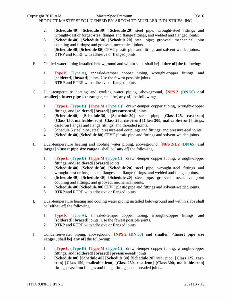
B. Hot-water heating piping, aboveground, [NPS 2-1/2 (DN 65) and larger] <Insert pipe size
range>, shall be[ any of] the following:
1. [Type L (Type B)] [Type M (Type C)], drawn-temper copper tubing, wrought-copper
fittings, and [soldered] [brazed] joints.
2. [Schedule 40] [Schedule 30] [Schedule 20] steel pipe, wrought-steel fittings and
wrought-cast or forged-steel flanges and flange fittings, and welded and flanged joints.
3. [Schedule 40] [Schedule 30] [Schedule 20] steel pipe; grooved, mechanical joint
coupling and fittings; and grooved, mechanical joints.
4. [Schedule 40] [Schedule 80] CPVC plastic pipe and fittings and solvent-welded joints.
5. RTRP and RTRF with adhesive or flanged joints.
C. Hot-water heating piping installed belowground and within slabs shall be[ either of] the
following:
1. Type K (Type A), annealed-temper copper tubing, wrought-copper fittings, and
[soldered] [brazed] joints. Use the fewest possible joints.
2. RTRP and RTRF with adhesive or flanged joints.
D. Chilled-water piping, aboveground, [NPS 2 (DN 50) and smaller] <Insert pipe size range>,
shall be[ any of] the following:
1. [Type L (Type B)] [Type M (Type C)], drawn-temper copper tubing, wrought-copper
fittings, and [soldered] [brazed] [pressure-seal] joints.
2. [Schedule 40] [Schedule 30] [Schedule 20] steel pipe; [Class 125, cast-iron]
[Class 150, malleable-iron] [Class 250, cast-iron] [Class 300, malleable-iron] fittings;
cast-iron flanges and flange fittings; and threaded joints.
3. Schedule 5 steel pipe; steel, pressure-seal couplings and fittings; and pressure-seal joints.
4. [Schedule 40] [Schedule 80] CPVC plastic pipe and fittings and solvent-welded joints.
E. Chilled-water piping, aboveground, [NPS 2-1/2 (DN 65) and larger] <Insert pipe size range>,
shall be[ any of] the following:
1. [Type L (Type B)] [Type M (Type C)], drawn-temper copper tubing, wrought-copper
fittings, and [soldered] [brazed] joints.
Copyright 2016 AIA MasterSpec Premium 03/16
PRODUCT MASTERSPEC LICENSED BY ARCOM TO MUELLER INDUSTRIES, INC.
HYDRONIC PIPING 232113 - 12
2. [Schedule 40] [Schedule 30] [Schedule 20] steel pipe, wrought-steel fittings and
wrought-cast or forged-steel flanges and flange fittings, and welded and flanged joints.
3. [Schedule 40] [Schedule 30] [Schedule 20] steel pipe; grooved, mechanical joint
coupling and fittings; and grooved, mechanical joints.
4. [Schedule 40] [Schedule 80] CPVC plastic pipe and fittings and solvent-welded joints.
5. RTRP and RTRF with adhesive or flanged joints.
F. Chilled-water piping installed belowground and within slabs shall be[ either of] the following:
1. Type K (Type A), annealed-temper copper tubing, wrought-copper fittings, and
[soldered] [brazed] joints. Use the fewest possible joints.
2. RTRP and RTRF with adhesive or flanged joints.
G. Dual-temperature heating and cooling water piping, aboveground, [NPS 2 (DN 50) and
smaller] <Insert pipe size range>, shall be[ any of] the following:
1. [Type L (Type B)] [Type M (Type C)], drawn-temper copper tubing, wrought-copper
fittings, and [soldered] [brazed] [pressure-seal] joints.
2. [Schedule 40] [Schedule 30] [Schedule 20] steel pipe; [Class 125, cast-iron]
[Class 150, malleable-iron] [Class 250, cast-iron] [Class 300, malleable-iron] fittings;
cast-iron flanges and flange fittings; and threaded joints.
3. Schedule 5 steel pipe; steel, pressure-seal couplings and fittings; and pressure-seal joints.
4. [Schedule 40] [Schedule 80] CPVC plastic pipe and fittings and solvent-welded joints.
H. Dual-temperature heating and cooling water piping, aboveground, [NPS 2-1/2 (DN 65) and
larger] <Insert pipe size range>, shall be[ any of] the following:
1. [Type L (Type B)] [Type M (Type C)], drawn-temper copper tubing, wrought-copper
fittings, and [soldered] [brazed] joints.
2. [Schedule 40] [Schedule 30] [Schedule 20] steel pipe, wrought-steel fittings and
wrought-cast or forged-steel flanges and flange fittings, and welded and flanged joints.
3. [Schedule 40] [Schedule 30] [Schedule 20] steel pipe; grooved, mechanical joint
coupling and fittings; and grooved, mechanical joints.
4. [Schedule 40] [Schedule 80] CPVC plastic pipe and fittings and solvent-welded joints.
5. RTRP and RTRF with adhesive or flanged joints.
I. Dual-temperature heating and cooling water piping installed belowground and within slabs shall
be[ either of] the following:
1. Type K (Type A), annealed-temper copper tubing, wrought-copper fittings, and
[soldered] [brazed] joints. Use the fewest possible joints.
2. RTRP and RTRF with adhesive or flanged joints.
J. Condenser-water piping, aboveground, [NPS 2 (DN 50) and smaller] <Insert pipe size
range>, shall be[ any of] the following:
1. [Type L (Type B)] [Type M (Type C)], drawn-temper copper tubing, wrought-copper
fittings, and [soldered] [brazed] [pressure-seal] joints.
2. [Schedule 80] [Schedule 40] [Schedule 30] [Schedule 20] steel pipe; [Class 125, cast-
iron] [Class 150, malleable-iron] [Class 250, cast-iron] [Class 300, malleable-iron]
fittings; cast-iron flanges and flange fittings; and threaded joints.
Copyright 2016 AIA MasterSpec Premium 03/16
PRODUCT MASTERSPEC LICENSED BY ARCOM TO MUELLER INDUSTRIES, INC.
HYDRONIC PIPING 232113 - 13
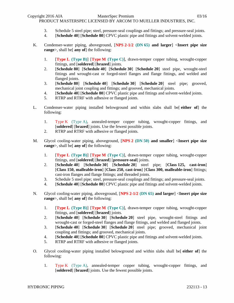
3. Schedule 5 steel pipe; steel, pressure-seal couplings and fittings; and pressure-seal joints.
4. [Schedule 40] [Schedule 80] CPVC plastic pipe and fittings and solvent-welded joints.
K. Condenser-water piping, aboveground, [NPS 2-1/2 (DN 65) and larger] <Insert pipe size
range>, shall be[ any of] the following:
1. [Type L (Type B)] [Type M (Type C)], drawn-temper copper tubing, wrought-copper
fittings, and [soldered] [brazed] joints.
2. [Schedule 80] [Schedule 40] [Schedule 30] [Schedule 20] steel pipe, wrought-steel
fittings and wrought-cast or forged-steel flanges and flange fittings, and welded and
flanged joints.
3. [Schedule 80] [Schedule 40] [Schedule 30] [Schedule 20] steel pipe; grooved,
mechanical joint coupling and fittings; and grooved, mechanical joints.
4. [Schedule 40] [Schedule 80] CPVC plastic pipe and fittings and solvent-welded joints.
5. RTRP and RTRF with adhesive or flanged joints.
L. Condenser-water piping installed belowground and within slabs shall be[ either of] the
following:
1. Type K (Type A), annealed-temper copper tubing, wrought-copper fittings, and
[soldered] [brazed] joints. Use the fewest possible joints.
2. RTRP and RTRF with adhesive or flanged joints.
M. Glycol cooling-water piping, aboveground, [NPS 2 (DN 50) and smaller] <Insert pipe size
range>, shall be[ any of] the following:
1. [Type L (Type B)] [Type M (Type C)], drawn-temper copper tubing, wrought-copper
fittings, and [soldered] [brazed] [pressure-seal] joints.
2. [Schedule 40] [Schedule 30] [Schedule 20] steel pipe; [Class 125, cast-iron]
[Class 150, malleable-iron] [Class 250, cast-iron] [Class 300, malleable-iron] fittings;
cast-iron flanges and flange fittings; and threaded joints.
3. Schedule 5 steel pipe; steel, pressure-seal couplings and fittings; and pressure-seal joints.
4. [Schedule 40] [Schedule 80] CPVC plastic pipe and fittings and solvent-welded joints.
N. Glycol cooling-water piping, aboveground, [NPS 2-1/2 (DN 65) and larger] <Insert pipe size
range>, shall be[ any of] the following:
1. [Type L (Type B)] [Type M (Type C)], drawn-temper copper tubing, wrought-copper
fittings, and [soldered] [brazed] joints.
2. [Schedule 40] [Schedule 30] [Schedule 20] steel pipe, wrought-steel fittings and
wrought-cast or forged-steel flanges and flange fittings, and welded and flanged joints.
3. [Schedule 40] [Schedule 30] [Schedule 20] steel pipe; grooved, mechanical joint
coupling and fittings; and grooved, mechanical joints.
4. [Schedule 40] [Schedule 80] CPVC plastic pipe and fittings and solvent-welded joints.
5. RTRP and RTRF with adhesive or flanged joints.
O. Glycol cooling-water piping installed belowground and within slabs shall be[ either of] the
following:
1. Type K (Type A), annealed-temper copper tubing, wrought-copper fittings, and
[soldered] [brazed] joints. Use the fewest possible joints.
Copyright 2016 AIA MasterSpec Premium 03/16
PRODUCT MASTERSPEC LICENSED BY ARCOM TO MUELLER INDUSTRIES, INC.
HYDRONIC PIPING 232113 - 14
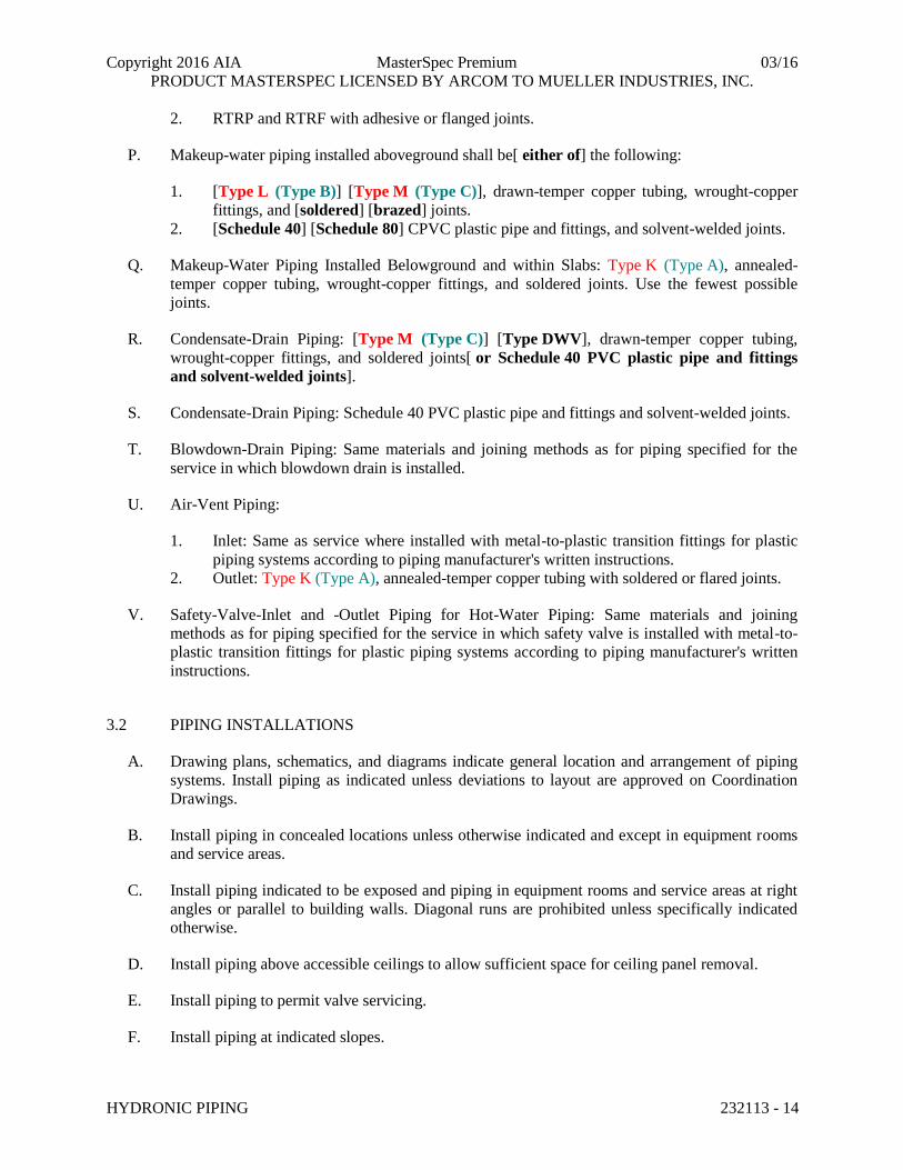
2. RTRP and RTRF with adhesive or flanged joints.
P. Makeup-water piping installed aboveground shall be[ either of] the following:
1. [Type L (Type B)] [Type M (Type C)], drawn-temper copper tubing, wrought-copper
fittings, and [soldered] [brazed] joints.
2. [Schedule 40] [Schedule 80] CPVC plastic pipe and fittings, and solvent-welded joints.
Q. Makeup-Water Piping Installed Belowground and within Slabs: Type K (Type A), annealed-
temper copper tubing, wrought-copper fittings, and soldered joints. Use the fewest possible
joints.
R. Condensate-Drain Piping: [Type M (Type C)] [Type DWV], drawn-temper copper tubing,
wrought-copper fittings, and soldered joints[ or Schedule 40 PVC plastic pipe and fittings
and solvent-welded joints].
S. Condensate-Drain Piping: Schedule 40 PVC plastic pipe and fittings and solvent-welded joints.
T. Blowdown-Drain Piping: Same materials and joining methods as for piping specified for the
service in which blowdown drain is installed.
U. Air-Vent Piping:
1. Inlet: Same as service where installed with metal-to-plastic transition fittings for plastic
piping systems according to piping manufacturer's written instructions.
2. Outlet: Type K (Type A), annealed-temper copper tubing with soldered or flared joints.
V. Safety-Valve-Inlet and -Outlet Piping for Hot-Water Piping: Same materials and joining
methods as for piping specified for the service in which safety valve is installed with metal-to-
plastic transition fittings for plastic piping systems according to piping manufacturer's written
instructions.
3.2 PIPING INSTALLATIONS
A. Drawing plans, schematics, and diagrams indicate general location and arrangement of piping
systems. Install piping as indicated unless deviations to layout are approved on Coordination
Drawings.
B. Install piping in concealed locations unless otherwise indicated and except in equipment rooms
and service areas.
C. Install piping indicated to be exposed and piping in equipment rooms and service areas at right
angles or parallel to building walls. Diagonal runs are prohibited unless specifically indicated
otherwise.
D. Install piping above accessible ceilings to allow sufficient space for ceiling panel removal.
E. Install piping to permit valve servicing.
F. Install piping at indicated slopes.

Copyright 2016 AIA MasterSpec Premium 03/16
PRODUCT MASTERSPEC LICENSED BY ARCOM TO MUELLER INDUSTRIES, INC.
HYDRONIC PIPING 232113 - 15
G. Install piping free of sags and bends.
H. Install fittings for changes in direction and branch connections.
I. Install piping to allow application of insulation.
J. Select system components with pressure rating equal to or greater than system operating
pressure.
K. Install groups of pipes parallel to each other, spaced to permit applying insulation and servicing
of valves.
L. Install drains, consisting of a tee fitting, NPS 3/4 (DN 20) ball valve, and short NPS 3/4
(DN 20) threaded nipple with cap, at low points in piping system mains and elsewhere as
required for system drainage.
M. Install piping at a uniform grade of 0.2 percent upward in direction of flow.
N. Reduce pipe sizes using eccentric reducer fitting installed with level side up.
O. Install branch connections to mains using [mechanically formed ]tee fittings in main pipe, with
the branch connected to the bottom of the main pipe. For up-feed risers, connect the branch to
the top of the main pipe.
P. Install valves according to the following:
1. Section 230523.11 "Globe Valves for HVAC Piping."
2. Section 230523.12 "Ball Valves for HVAC Piping."
3. Section 230523.13 "Butterfly Valves for HVAC Piping."
4. Section 230523.14 "Check Valves for HVAC Piping."
5. Section 230523.15 "Gate Valves for HVAC Piping."
Q. Install unions in piping, [NPS 2 (DN 50)] <Insert pipe size> and smaller, adjacent to valves, at
final connections of equipment, and elsewhere as indicated.
R. Install flanges in piping, [NPS 2-1/2 (DN 65)] <Insert pipe size> and larger, at final
connections of equipment and elsewhere as indicated.
S. Install shutoff valve immediately upstream of each dielectric fitting.
T. Comply with requirements in Section 230516 "Expansion Fittings and Loops for HVAC
Piping" for installation of expansion loops, expansion joints, anchors, and pipe alignment
guides.
U. Comply with requirements in Section 230553 "Identification for HVAC Piping and Equipment"
for identifying piping.
V. Install sleeves for piping penetrations of walls, ceilings, and floors. Comply with requirements
for sleeves specified in Section 230517 "Sleeves and Sleeve Seals for HVAC Piping."

Copyright 2016 AIA MasterSpec Premium 03/16
PRODUCT MASTERSPEC LICENSED BY ARCOM TO MUELLER INDUSTRIES, INC.
HYDRONIC PIPING 232113 - 16
W. Install sleeve seals for piping penetrations of concrete walls and slabs. Comply with
requirements for sleeve seals specified in Section 230517 "Sleeves and Sleeve Seals for HVAC
Piping."
X. Install escutcheons for piping penetrations of walls, ceilings, and floors. Comply with
requirements for escutcheons specified in Section 230518 "Escutcheons for HVAC Piping."
3.3 DIELECTRIC FITTING INSTALLATION
A. Install dielectric fittings in piping at connections of dissimilar metal piping and tubing.
B. Dielectric Fittings for [NPS 2 (DN 50)] <Insert pipe size> and Smaller: Use dielectric
[nipples] [unions].
C. Dielectric Fittings for [NPS 2-1/2 to NPS 4 (DN 65 to DN 100)] <Insert pipe size range>: Use
dielectric [flanges] [flange kits] [nipples].
D. Dielectric Fittings for [NPS 5 (DN 125)] <Insert pipe size> and Larger: Use dielectric flange
kits.
3.4 HANGERS AND SUPPORTS
A. Comply with requirements in Section 230529 "Hangers and Supports for HVAC Piping and
Equipment" for hanger, support, and anchor devices. Comply with the following requirements
for maximum spacing of supports.
B. Comply with requirements in Section 230548 "Vibration and Seismic Controls for HVAC" for
seismic restraints.
C. Install the following pipe attachments:
1. Adjustable steel clevis hangers for individual horizontal piping less than 20 feet (6 m)
long.
2. Adjustable roller hangers and spring hangers for individual horizontal piping 20 feet
(6 m) or longer.
3. Pipe Roller: MSS SP-58, Type 44 for multiple horizontal piping 20 feet (6 m) or longer,
supported on a trapeze.
4. Spring hangers to support vertical runs.
5. Provide copper-clad hangers and supports for hangers and supports in direct contact with
copper pipe.
6. On plastic pipe, install pads or cushions on bearing surfaces to prevent hanger from
scratching pipe.
D. Install hangers for steel piping with the following maximum spacing and minimum rod sizes:
1. NPS 3/4 (DN 20): Maximum span, 7 feet (2.1 m).
2. NPS 1 (DN 25): Maximum span, 7 feet (2.1 m).
3. NPS 1-1/2 (DN 40): Maximum span, 9 feet (2.7 m).
4. NPS 2 (DN 50): Maximum span, 10 feet (3 m).
Copyright 2016 AIA MasterSpec Premium 03/16
PRODUCT MASTERSPEC LICENSED BY ARCOM TO MUELLER INDUSTRIES, INC.
HYDRONIC PIPING 232113 - 17
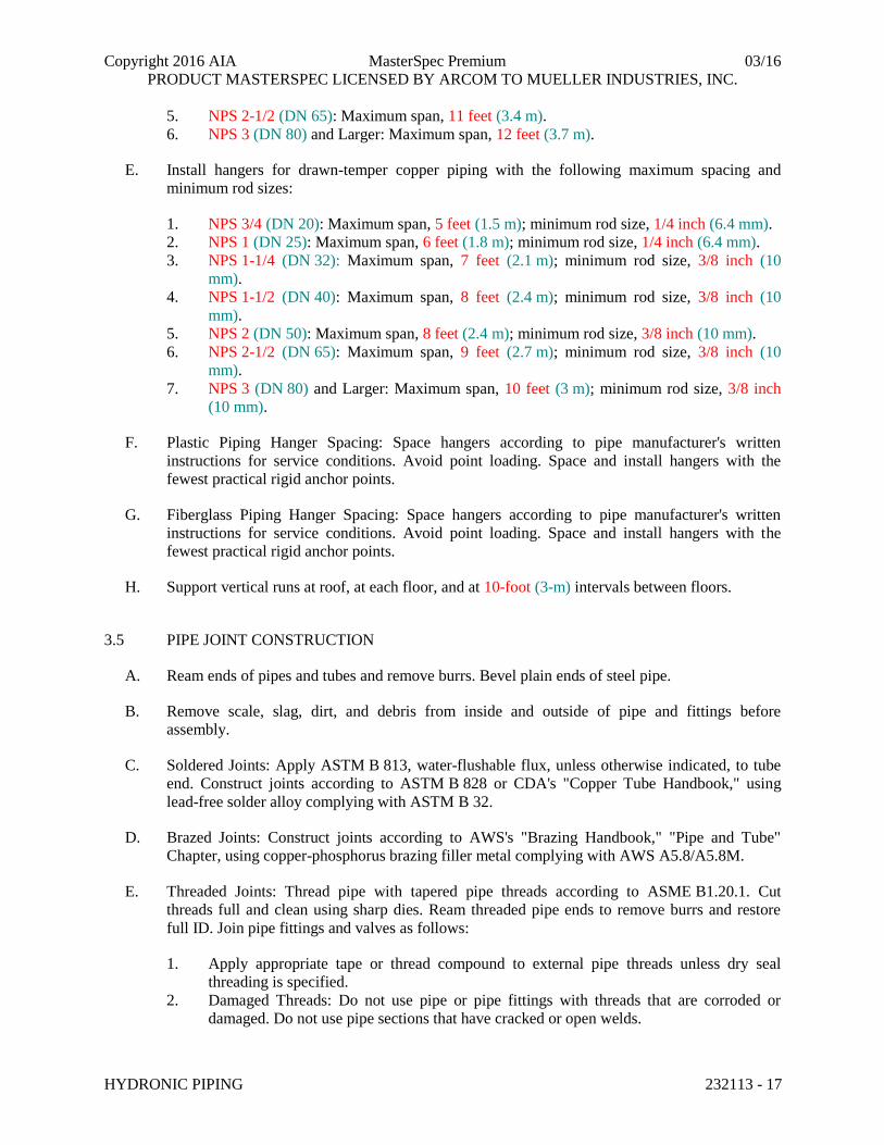
5. NPS 2-1/2 (DN 65): Maximum span, 11 feet (3.4 m).
6. NPS 3 (DN 80) and Larger: Maximum span, 12 feet (3.7 m).
E. Install hangers for drawn-temper copper piping with the following maximum spacing and
minimum rod sizes:
1. NPS 3/4 (DN 20): Maximum span, 5 feet (1.5 m); minimum rod size, 1/4 inch (6.4 mm).
2. NPS 1 (DN 25): Maximum span, 6 feet (1.8 m); minimum rod size, 1/4 inch (6.4 mm).
3. NPS 1-1/4 (DN 32): Maximum span, 7 feet (2.1 m); minimum rod size, 3/8 inch (10
mm).
4. NPS 1-1/2 (DN 40): Maximum span, 8 feet (2.4 m); minimum rod size, 3/8 inch (10
mm).
5. NPS 2 (DN 50): Maximum span, 8 feet (2.4 m); minimum rod size, 3/8 inch (10 mm).
6. NPS 2-1/2 (DN 65): Maximum span, 9 feet (2.7 m); minimum rod size, 3/8 inch (10
mm).
7. NPS 3 (DN 80) and Larger: Maximum span, 10 feet (3 m); minimum rod size, 3/8 inch
(10 mm).
F. Plastic Piping Hanger Spacing: Space hangers according to pipe manufacturer's written
instructions for service conditions. Avoid point loading. Space and install hangers with the
fewest practical rigid anchor points.
G. Fiberglass Piping Hanger Spacing: Space hangers according to pipe manufacturer's written
instructions for service conditions. Avoid point loading. Space and install hangers with the
fewest practical rigid anchor points.
H. Support vertical runs at roof, at each floor, and at 10-foot (3-m) intervals between floors.
3.5 PIPE JOINT CONSTRUCTION
A. Ream ends of pipes and tubes and remove burrs. Bevel plain ends of steel pipe.
B. Remove scale, slag, dirt, and debris from inside and outside of pipe and fittings before
assembly.
C. Soldered Joints: Apply ASTM B 813, water-flushable flux, unless otherwise indicated, to tube
end. Construct joints according to ASTM B 828 or CDA's "Copper Tube Handbook," using
lead-free solder alloy complying with ASTM B 32.
D. Brazed Joints: Construct joints according to AWS's "Brazing Handbook," "Pipe and Tube"
Chapter, using copper-phosphorus brazing filler metal complying with AWS A5.8/A5.8M.
E. Threaded Joints: Thread pipe with tapered pipe threads according to ASME B1.20.1. Cut
threads full and clean using sharp dies. Ream threaded pipe ends to remove burrs and restore
full ID. Join pipe fittings and valves as follows:
1. Apply appropriate tape or thread compound to external pipe threads unless dry seal
threading is specified.
2. Damaged Threads: Do not use pipe or pipe fittings with threads that are corroded or
damaged. Do not use pipe sections that have cracked or open welds.
Copyright 2016 AIA MasterSpec Premium 03/16
PRODUCT MASTERSPEC LICENSED BY ARCOM TO MUELLER INDUSTRIES, INC.
HYDRONIC PIPING 232113 - 18
F. Welded Joints: Construct joints according to AWS D10.12M/D10.12, using qualified processes
and welding operators according to "Quality Assurance" Article.
G. Flanged Joints: Select appropriate gasket material, size, type, and thickness for service
application. Install gasket concentrically positioned. Use suitable lubricants on bolt threads.
H. Plastic Piping Solvent-Cemented Joints: Clean and dry joining surfaces. Join pipe and fittings
according to the following:
1. Comply with ASTM F 402 for safe-handling practice of cleaners, primers, and solvent
cements.
2. CPVC Piping: Join according to ASTM D 2846/D 2846M Appendix.
3. PVC Pressure Piping: Join ASTM D 1785 schedule number, PVC pipe and PVC socket
fittings according to ASTM D 2672. Join other-than-schedule number PVC pipe and
socket fittings according to ASTM D 2855.
4. PVC Nonpressure Piping: Join according to ASTM D 2855.
I. Fiberglass Bonded Joints: Prepare pipe ends and fittings, apply adhesive, and join according to
pipe manufacturer's written instructions.
J. Grooved Joints: Assemble joints with coupling and gasket, lubricant, and bolts. Cut or roll
grooves in ends of pipe based on pipe and coupling manufacturer's written instructions for pipe
wall thickness. Use grooved-end fittings and rigid, grooved-end-pipe couplings.
K. Mechanically Formed, Copper-Tube-Outlet Joints: Use manufacturer-recommended tool and
procedure, and brazed joints.
L. Pressure-Sealed Joints: Use manufacturer-recommended tool and procedure. Leave insertion
marks on pipe after assembly.
3.6 TERMINAL EQUIPMENT CONNECTIONS
A. Sizes for supply and return piping connections shall be the same as or larger than equipment
connections.
B. Install control valves in accessible locations close to connected equipment.
C. Install bypass piping with globe valve around control valve. If parallel control valves are
installed, only one bypass is required.
D. Install ports for pressure gages and thermometers at coil inlet and outlet connections. Comply
with requirements in Section 230519 "Meters and Gages for HVAC Piping."
3.7 CHEMICAL TREATMENT
A. Perform an analysis of makeup water to determine type and quantities of chemical treatment
needed to keep system free of scale, corrosion, and fouling, and to sustain the following water
characteristics:

Copyright 2016 AIA MasterSpec Premium 03/16
PRODUCT MASTERSPEC LICENSED BY ARCOM TO MUELLER INDUSTRIES, INC.
HYDRONIC PIPING 232113 - 19
1. pH: [9.0 to 10.5] <Insert values>.
2. "P" Alkalinity: [100 to 500] <Insert values> ppm.
3. Boron: [100 to 200] <Insert values> ppm.
4. Chemical Oxygen Demand: Maximum of [100] <Insert value> ppm. Revise this value if
closed system contains glycol.
5. Corrosion Inhibitor:
a. Sodium Nitrate: [1000 to 1500] <Insert values> ppm.
b. Molybdate: [200 to 300] <Insert values> ppm.
c. Chromate: [200 to 300] <Insert values> ppm.
d. Sodium Nitrate Plus Molybdate: [100 to 200] <Insert values> ppm each.
e. Chromate Plus Molybdate: [50 to 100] <Insert values> ppm each.
6. Soluble Copper: Maximum of [0.20] <Insert value> ppm.
7. Tolyiriazole Copper and Yellow Metal Corrosion Inhibitor: Minimum of [10] <Insert
value> ppm.
8. Total Suspended Solids: Maximum of [10] <Insert value> ppm.
9. Ammonia: Maximum of [20] <Insert value> ppm.
10. Free Caustic Alkalinity: Maximum of [20] <Insert value> ppm.
11. Microbiological Limits:
a. Total Aerobic Plate Count: Maximum of [1000] <Insert number> organisms/mL.
b. Total Anaerobic Plate Count: Maximum of [100] <Insert number>
organisms/mL.
c. Nitrate Reducers: [100] <Insert number> organisms/mL.
d. Sulfate Reducers: Maximum of [zero] <Insert number> organisms/mL.
e. Iron Bacteria: Maximum of [zero] <Insert number> organisms/mL.
12. <Insert other requirements if necessary>.
B. Install bypass chemical feeders in each hydronic system where indicated.
1. Install in upright position with top of funnel not more than 48 inches (1200 mm) above
the floor.
2. Install feeder in minimum NPS 3/4 (DN 20) bypass line, from main with full-size, full-
port, ball valve in the main between bypass connections.
3. Install NPS 3/4 (DN 20) pipe from chemical feeder drain to nearest equipment drain and
include a full-size, full-port, ball valve.
C. Fill system with fresh water and add liquid alkaline compound with emulsifying agents and
detergents to remove grease and petroleum products from piping. Circulate solution for a
minimum of 24 hours, drain, clean strainer screens, and refill with fresh water.
D. Add initial chemical treatment and maintain water quality in ranges noted above for the first
year of operation.
E. Fill systems that have antifreeze or glycol solutions with the following concentrations:
1. Hot-Water Heating Piping: Minimum of <Insert number> percent [ethylene]
[propylene] glycol.
Copyright 2016 AIA MasterSpec Premium 03/16
PRODUCT MASTERSPEC LICENSED BY ARCOM TO MUELLER INDUSTRIES, INC.
HYDRONIC PIPING 232113 - 20
2. Chilled-Water Piping: Minimum of <Insert number> percent [ethylene] [propylene]
glycol.
3. Dual-Temperature Heating and Cooling Water Piping: Minimum of <Insert number>
percent [ethylene] [propylene] glycol.
4. Glycol Cooling-Water Piping: Minimum of <Insert number> percent [ethylene]
[propylene] glycol.
3.8 FIELD QUALITY CONTROL
A. Prepare hydronic piping according to ASME B31.9 and as follows:
1. Leave joints, including welds, uninsulated and exposed for examination during test.
2. Provide temporary restraints for expansion joints that cannot sustain reactions due to test
pressure. If temporary restraints are impractical, isolate expansion joints from testing.
3. Flush hydronic piping systems with clean water; then remove and clean or replace
strainer screens.
4. Isolate equipment from piping. If a valve is used to isolate equipment, its closure shall be
capable of sealing against test pressure without damage to valve. Install blinds in flanged
joints to isolate equipment.
5. Install safety valve, set at a pressure no more than one-third higher than test pressure, to
protect against damage by expanding liquid or other source of overpressure during test.
B. Perform the following tests on hydronic piping:
1. Use ambient temperature water as a testing medium unless there is risk of damage due to
freezing. Another liquid that is safe for workers and compatible with piping may be used.
2. While filling system, use vents installed at high points of system to release air. Use drains
installed at low points for complete draining of test liquid.
3. Isolate expansion tanks and determine that hydronic system is full of water.
4. Subject piping system to hydrostatic test pressure that is not less than 1.5 times the
system's working pressure. Test pressure shall not exceed maximum pressure for any
vessel, pump, valve, or other component in system under test. Verify that stress due to
pressure at bottom of vertical runs does not exceed 90 percent of specified minimum
yield strength or 1.7 times the "SE" value in Appendix A in ASME B31.9, "Building
Services Piping."
5. After hydrostatic test pressure has been applied for at least 10 minutes, examine piping,
joints, and connections for leakage. Eliminate leaks by tightening, repairing, or replacing
components, and repeat hydrostatic test until there are no leaks.
6. Prepare written report of testing.
C. Perform the following before operating the system:
1. Open manual valves fully.
2. Inspect pumps for proper rotation.
3. Set makeup pressure-reducing valves for required system pressure.
4. Inspect air vents at high points of system and determine if all are installed and operating
freely (automatic type), or bleed air completely (manual type).
5. Set temperature controls so all coils are calling for full flow.
6. Inspect and set operating temperatures of hydronic equipment, such as boilers, chillers,
cooling towers, to specified values.
Copyright 2016 AIA MasterSpec Premium 03/16
PRODUCT MASTERSPEC LICENSED BY ARCOM TO MUELLER INDUSTRIES, INC.
HYDRONIC PIPING 232113 - 21
7. Verify lubrication of motors and bearings.
END OF SECTION 232113