copyright asme international provided by ihs under...
TRANSCRIPT
Copyright ASME International Provided by IHS under license with ASME
Document provided by IHS Licensee=Qatar Petroleum/5943408001, 09/19/200422:36:17 MDT Questions or comments about this message: please call the DocumentPolicy Group at 303-397-2295.
--```,,`,``,,,,`,,``````,,``,`-`-`,,`,,`,`,,`---

Copyright ASME International Provided by IHS under license with ASME
Document provided by IHS Licensee=Qatar Petroleum/5943408001, 09/19/200422:36:17 MDT Questions or comments about this message: please call the DocumentPolicy Group at 303-397-2295.
--```,,`,``,,,,`,,``````,,``,`-`-`,,`,,`,`,,`---
The American Society of Mechanical Engineers
A N A M E R I C A N N A T I O N A L S T A N D A R D
PIPE FLANGES AND FLANGED FITTINGS
I P S '/2 Through I P S 24 MetPic/lnch
ASME B16.5-2003 (Revision of ASME 11 6.5-1 196)
Copyright ASME International Provided by IHS under license with ASME
Document provided by IHS Licensee=Qatar Petroleum/5943408001, 09/19/200422:36:17 MDT Questions or comments about this message: please call the DocumentPolicy Group at 303-397-2295.
--```,,`,``,,,,`,,``````,,``,`-`-`,,`,,`,`,,`---
Date of Issuance: November 28, 2003
The 2003 edition of this Standard is being issued with an automatic addenda subscription service. The use of addenda allows' revisions made in response to public review comments or committee actions to be published as necessary. This Standard will be revised when the Society approves the issuance of a new edition.
ASME issues written replies to inquiries concerning interpretations of technical aspects of this Standard. The interpretations will be included with the above addenda service.
ASME is the registered trademark of The American Society of Mechanical Engineers.
This code or standard was developed under procedures accredited as meeting the criteria for American National Standards. The Standards Committee that approved the code or standard was balanced to assure that individuals from competent and concerned interests have had an opportunity to participate. The proposed code or standard was made available for public review and comment that provides an opportunity for additional public input from industry, academia, regulatory agencies, and the public-at-large.
ASME does not "approve," "rate," or "endorse" any item, construction, proprietary device, or activity. ASME does not take any position with respect to the validity of any patent rights asserted in connection with any
items mentioned in this document, and does not undertake to insure anyone utilizing a standard against liability for infringement of any applicable letters patent, nor assumes any such liability. Users of a code or standard are expressly advised that determination of the validity of any such patent rights, and the risk of infringement of such rights, is entirely their own responsibility.
Participation by federal agency representative(s) or person(s) affiliated with industry is not to be interpreted as government or industty endorsement of this code or standard.
ASME accepts responsibility for only those interpretations of this document issued in accordance with the established ASME procedures and policies, which precludes the issuance of interpretations by individuals.
No part of this document may be reproduced in any form, in an electronic retrieval system or otherwise,
without the prior written permission of the publisher.
The American Society of Mechanical Engineers Three Park Avenue, New York, NY 10016-5990
Copyright O 2003 by THE AMERICAN SOCIETY OF MECHANICAL ENGINEERS
All rights reserved Printed in U.S.A.
Copyright ASME International Provided by IHS under license with ASME
Document provided by IHS Licensee=Qatar Petroleum/5943408001, 09/19/200422:36:17 MDT Questions or comments about this message: please call the DocumentPolicy Group at 303-397-2295.
--```,,`,``,,,,`,,``````,,``,`-`-`,,`,,`,`,,`---

Foreword ........................................................................ vi Committee Roster ................................................................ ix Correspondence With the 816 Committee ......................................... x
1 Scope ................................................................... 1
2 Pressure-Temperature Ratings ............................................. 2
3 Component Size ......................................................... 3
Marking ................................................................. 3 4
5 Materiais ................................................................ 6
6 Dimensions .............................................................. 9
7 Tolerances ............................................................... 12
8 Pressure Testing ......................................................... 14
Figures 1
2 3 4 5 6 7
8 9 30 11 12 13 14 15
Tab les 1A 1B 1c 2-1.1 2-1.2 2-1.3 2-1.4 2-1.5 2-1.7 2-1.9
Method of Designating Location of Auxiliary Connections When
Method of Designating Outlets of Reducing Fittings in Specifications ...... Specified .............................................................. 15
16 Thread Length for Connection Tapping ................................... 17 Socket Welding for Connections .......................................... 17 Butt Welding for Connections ............................................ 17 Bosses for Connections ................................................... 17 End Flange Facings and Their Relationship to Flange Thickness and
Center-to-End and End-to-End Dimensions ............................. 18 Bevel for Wall Thicknesses f From 5 mm to 22 nun Inclusive .............. 20 Bevel for Wall Thicknesses t Greater Than 22 mm ......................... 20 Inside Contour for Use With Rectangular Backing Ring ................... 21 Inside Contour for Use With Taper Backing Ring .......................... 21 Bevel for Outside Thickness .............................................. 22 Bevel for Inside Thickness ................................................. 22 Bevel for Combined Thickness ........................................... 22 Straight Hub Welding Flanges ............................................ 22
List of Material Specifications ............................................ List of Bolting Specifications Applicable ASTM Specifications ............. Flange Bolting Dimensional Recommendations ............................ Pressure-Temperature Ratings for Group 1.1 Materials .................... Pressure-Temperature Ratings for Group 1.2 Materials .................... Pressure-Temperature Ratings for Group 1.3 Materials .................... Pressure-Temperature Ratings for Group 1.4 Materials .................... Pressure-Temperature Ratings for Group 1.5 Materials .................... Pressure-Temperature Ratings for Group 1.7 Materials .................... Pressure-Temperature Ratings for Group 1.9 Materials ....................
4 7
12 23 24 25 26 27 28 29
iii Copyright ASME International Provided by IHS under license with ASME
Document provided by IHS Licensee=Qatar Petroleum/5943408001, 09/19/200422:36:17 MDT Questions or comments about this message: please call the DocumentPolicy Group at 303-397-2295.
--```,,`,``,,,,`,,``````,,``,`-`-`,,`,,`,`,,`---

2-1.10 2-1.11 2-1.13 2-1.14 2-1.15 2-1.17 2-2.1 2-2.2 2-2.3 2-2.4 2-2.5 2-2.6 2-2.7 2-2.8 2-2.9 2-2.10 2-2.1 1 2-2.12 2-3.1 2-3.2 2-3.3 2-3.4 2-3.5 2-3.6 2-3.7 2-3.8 2-3.9 2-3.10 2-3.11 2-3.12 2-3.13 2-3.14 2-3.15 2-3.16 2-3.17 3
4
5 6 7 8 9 10 11 12 13 14 15 16 17 18 19 20 21
Pressure-Temperature Ratings for Group 1.10 Materials ................... Pressure-Temperature Ratings for Group 1.11 Materials ................... Pressure-Temperature Ratings for Group 1.13 Materials ................... Pressure-Temperature Ratings for Group 1.14 Materials ................... Pressure-Temperature Ratings for Group 1.15 Materials ................... Pressure-Temperature Ratings for Group 1.17 Materials ................... Pressure-Temperature Ratings for Group 2.1 Materials .................... Pressure-Temperature Ratings for Group 2.2 Materials ....................
Pressure-Temperature Ratings for Group 2.5 Materials ....................
Pressure-Temperature Ratings for Group 2.3 Materials .................... Pressure-Temperature Ratings for Group 2.4 Materials ....................
Pressure-Temperature Ratings for Group 2.6 Materials .................... Pressure-Temperature Ratings for Group 2.7 Materials .................... Pressure-Temperature Ratings for Group 2.8 Materials .................... Pressure-Temperature Ratings for Group 2.9 Materials .................... Pressure-Temperature Ratings for Group 2.10 Materials ................... Pressure-Temperature Ratings for Group 2.11 Materials ................... Pressure-Temperature Ratings for Group 2.12 Materials ................... Pressure-Temperature Ratings for Group 3.1 Materials .................... Pressure-Temperature Ratings for Group 3.2 Materials .................... Pressure-Temperature Ratings for Group 3.3 Materials .................... Pressure-Temperature Ratings for Group 3.4 Materials .................... Pressure-Temperature Ratings for Group 3.5 Materials .................... Pressure-Temperature Ratings for Group 3.6 Materials .................... Pressure-Temperature Ratings for Group 3.7 Materials .................... Pressure-Temperature Ratings for Group 3.8 Materials .................... Pressure-Temperature Ratings for Group 3.9 Materials .................... Pressure-Temperature Ratings for Group 3.10 Materials ................... Pressure-Temperature Ratings for Group 3.11 Materials ................... Pressure-Temperature Ratings for Group 3.12 Materials ................... Pressure-Temperature Ratings for Group 3.13 Materials ................... Pressure-Temperature Ratings for Group 3.14 Materials ................... Pressure-Temperature Ratings for Group 3.15 Materials ................... Pressure-Temperature Ratings for Group 3.16 Materials ................... Pressure-Temperature Ratings for Group 3.17 Materials ................... Permissible Imperfections in Flange Facing Finish for Raised Face and
Large Male and Female Flanges ........................................ Dimensions of Facings (Other Than Ring Joints, All Pressure Rating
Classes) ............................................................... Dimensions of Ring-Joint Facings (All Pressure Rating Classes) ............ Reducing Threaded and Slip-& Flanges for Classes 150 Through 2500 .... Templates for Drilling Class 150 Flanges .................................. Dimensions of Class 150 Flanges ......................................... Dimensions of Class 150 Flanged Fittings ................................. Templates for Drilling Class 300 Flanges .................................. Dimensions of Class 300 Flanges ......................................... Dimensions of Class 300 Flanged Fittings ................................. Templates for Drilling Class 400 Flanges .................................. Dimensions of Class 400 Flanges ......................................... Templates for Drilling Class 600 Flanges .................................. Dimensions of Class 600 Flanges ......................................... Templates for Drilling Class 900 Flanges .................................. Dimensions of Class 900 Flanges ......................................... Templates for Drilling Class 1500 Flanges ................................. Dimensions of Class 1500 Flanges ........................................ Templates for Drilling Class 2500 Flanges .................................
30 31 32 33 34 35 36 37 38 39 40 41 42 43 44 45 46 47 48 48 49 50 51 52 53 54 55 56 56 57 57 58 59 60 61
61
62 64 68 69 70 73 78 79 82 86 87 89 90 92 93 95 96 98
iv
Copyright ASME International Provided by IHS under license with ASME
Document provided by IHS Licensee=Qatar Petroleum/5943408001, 09/19/200422:36:17 MDT Questions or comments about this message: please call the DocumentPolicy Group at 303-397-2295.
--```,,`,``,,,,`,,``````,,``,`-`-`,,`,,`,`,,`---

22 Dimensions of Class 2500 Flanges ........................................ 99
Annexes A
C
Threading of Pipe for American National Standard Thread Flanges. .......
Limiting Dimensions of Gaskets Other Than Ring Joint Gaskets ...........
101
107 B Method Used for Establishing Pressure-Temperature Ratings .............. 103
D Method for Calculating Bolt Lengths ..................................... 109 E Quality System Program ................................................. 111 F Pressure-Temperature Ratings and Dimensional Data for Classes 150, 300,
400, 600, 900,1500, and 2500 Flanges and Classes 150 and 300 Flanged Fittings in U.S. Customary Units.. ............................. 112
G Dimensions of Classes 400, 600,900,1500, and 2500 Flanged Fittings in
H References ............................................................... 214 US. Customary Units.. ................................................ 195
V
Copyright ASME International Provided by IHS under license with ASME
Document provided by IHS Licensee=Qatar Petroleum/5943408001, 09/19/200422:36:17 MDT Questions or comments about this message: please call the DocumentPolicy Group at 303-397-2295.
--```,,`,``,,,,`,,``````,,``,`-`-`,,`,,`,`,,`---
FOREWORD
In 1920, the American Engineering Standards Committee[later the American Standards Associa- tions (ASA)] organized Sectional Committee 816 to unify and further develop standards for pipe flanges and fittings (and later for valves and gaskets). Co-sponsors of the B16 Committee were the American Society of Mechanical Engineers (ACME), the Heating and Piping Contractors National Association [now Mechanical Contractors Association of America (MCAA)], and the Manufacturers Standardization Society of the Valves and Fittings Industry (MSS). Co-sponsors were later designated as Co-secretariat organizations.
The committee soon recognized the need for standardization of steel pipe flanges. In May, 1923, Subcommittee 3 was organized to develop such standards for pressures in the 250 psi to 3200 psi range and for elevated temperatures. Active work began in October, including steel flanged fittings. The first proposed standard was submitted to the Committee in April 1926 and approved by letter ballot in December. After favorable review by the three sponsor organizations, the Standard was approved as American Tentative Standard B16e in June 1927.
Experience in using the Standard showed the need for hub dimensions of companion flanges and for other changes, including rerating of 250 lb and 1350 lb flanges and development of flanged fittings with integral bases. An investigation was made into the factors determining stiffness of flanges and flange hubs. The revised edition was approved as ASA B16E-1932.
A revision was initiated in 1936, stimulated by suggestions from Committee members and industrial users. The resulting 1939 edition contained standards for welding neck flanges (com- pleted in March 1937), 1500 lb flanges in the 14 in. through 24 in. range 2500 lb flanges and flanged fittings in the '4 in. through 12-in. range, and dimensions for a full line of ring joint flanges developed by the American Petroleum Institute. Pressure-temperature ratings for alloy steel flanges and fittings, developed by Subcommittee 4, were included for the first time.
In August 1942, the War Production Board requested a review of measures to conserve vital materials in piping components. A special War Committee of B16 was appointed and, operating under War Standard Procedure, developed revised pressure-temperature ratings for all materials and all pressure classes. The ratings were published as American War Standard B16e5-1943. In 1945, under normal procedures, Subcommittees 3 and 4 reviewed the 1939 standard and the 1943 ratings, and recommended adoption of the wartime ratings. Their report was approved as Supplement No. 1 to B16e-1939 and published as ASA B16e6-1949. In addition to ratings, the supplement updated material specification references and added a table of metal wall thickness for welding-end valves.
Subcommittee 3 then began a revision of the entire standard. Technically, the 1949 Supplement was absorbed, new materials were recognized, a general rating method was developed and added as an appendix, and welding end preparations were expanded. Editorially, a new style of presentation was worked out, including tables rearranged for easier use. Approval by Sectional Committee, cosponsors, and ASA resulted in publication of ASA B16.5-1953 (designation changed from B16e).
Work soon began on further revisions. Class B ratings were deleted and Class A ratings were clarified as the standard. An appendix defined qualifications for gaskets, other than ring joint, which would merit the ratings. Another appendix defined the method for calculating bolt lengths (including measurement of the length of stud bolts between thread ends instead of between points). Pressure-temperature ratings for several new materials were added, the table of welding end dimensions was expanded, and the temperatures used in determining ratings were redefined. The resulting new edition, after approval, was published as ASA B16.5-1957.
The more modest revision approved as ASA 816.5-1961 changed the text to clarify the intent or to make requirements easier to administer. The next revision began in 1963 with nearly 100 comments and suggestions. No fundamental changes were made, but the text was further clarified and wall thicknesses less then '/4 in. for flanged fittings were recognized in the 1968 edition.
vi
Copyright ASME International Provided by IHS under license with ASME
Document provided by IHS Licensee=Qatar Petroleum/5943408001, 09/19/200422:36:17 MDT Questions or comments about this message: please call the DocumentPolicy Group at 303-397-2295.
--```,,`,``,,,,`,,``````,,``,`-`-`,,`,,`,`,,`---
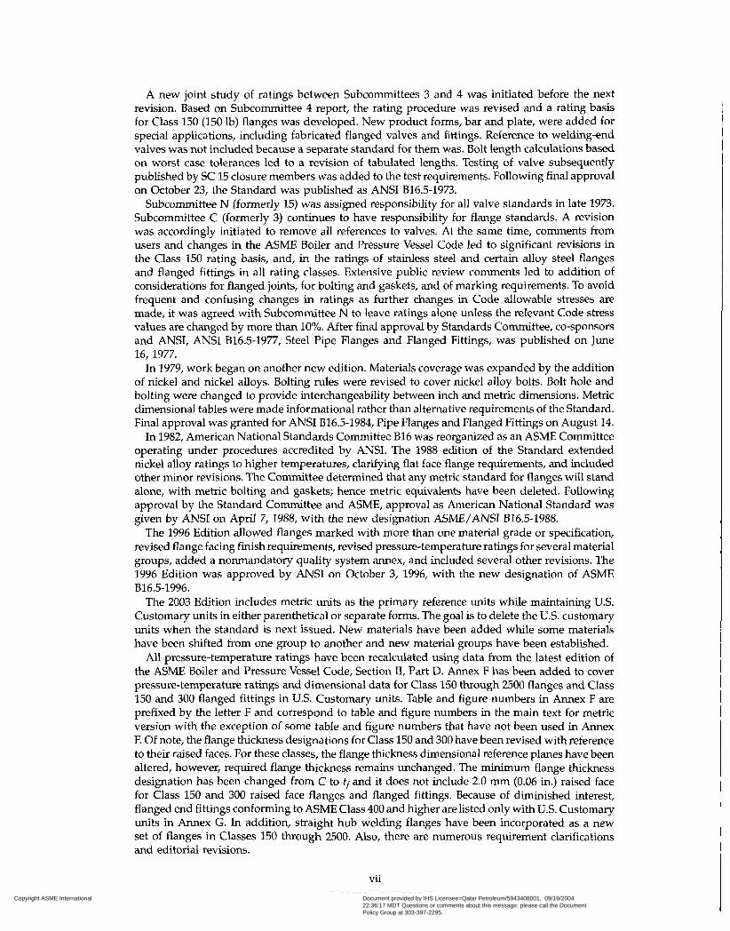
A new joint study of ratings between Subcommittees 3 and 4 was initiated before the next revision. Based on Subcommittee 4 report, the rating procedure was revised and a rating basis for Class 150 (150 lb) flanges was developed. New product forms, bar and plate, were added for special applications, including fabricated flanged valves and fittings. Reference to welding-end valves was not included because a separate standard for them was. Bolt length calculations based on worst case tolerances led to a revision of tabulated lengths. Testing of valve subsequently published by SC 15 closure members was added to the test requirements. Following final approval on October 23, the Standard was published as ANSI B16.5-1973.
Subcommittee N (formerly 15) was assigned responsibility for all valve standards in late 1973. Subcommittee C (formerly 3) continues to have responsibility for flange standards. A revision was accordingly initiated to remove all references to valves. At the same time, comments from users and changes in the ACME Boiler and Pressure Vessel Code led to significant revisions in the Class 150 rating basis, and, in the ratings of stainless steel and certain alloy steel flanges and flanged fittings in all rating classes. Extensive public review comments led to addition of considerations for flanged joints, for bolting and gaskets, and of marking requirements. To avoid frequent and confusing changes in ratings as further changes in Code allowable stresses are made, it was agreed with Subcommittee N to leave ratings alone unless the relevant Code stress values are changed by more than 10%. After final approval by Standards Committee, Co-sponsors and ANSI, ANSI B16.5-1977, Steel Pipe Flanges and Flanged Fittings, was published on June 16, 1977.
In 1979, work began on another new edition. Materials coverage was expanded by the addition of nickel and nickel alloys. Bolting rules were revised to cover nickel alloy bolts. Bolt hole and bolting were changed to provide interchangeability between inch and metric dimensions. Metric dimensional tables were made informational rather than alternative requirements of the Standard. Final approval was granted for ANSI B16.5-1984, Pipe Flanges and Flanged Fittings on August 14.
In 1982, American National Standards Committee B16 was reorganized as an ASME Committee operating under procedures accredited by ANSI. The 1988 edition of the Standard extended nickel alloy ratings to higher temperatures, clarifying flat face flange requirements, and included other minor revisions. The Committee determined that any metric standard for flanges will stand alone, with metric bolting and gaskets; hence metric equivalents have been deleted. Following approval by the Standard Committee and ASME, approval as American National Standard was given by ANSI on April 7, 1988, with the new designation ASME/ANSI B16.5-1988.
The 1996 Edition allowed flanges marked with more than one material grade or specification, revised flange facing finish requirements, revised pressure-temperature ratings for several material groups, added a nonmandatory quality system annex, and included several other revisions. The 1996 Edition was approved by ANSI on October 3, 1996, with the new designation of ACME
The 2003 Edition includes metric units as the primary reference units while maintaining U.S. Customary units in either parenthetical or separate forms. The goal is to delete the U.S. customary units when the standard is next issued. New materials have been added while some materials have been shifted from one group to another and new material groups have been established.
All pressure-temperature ratings have been recalculated using data from the latest edition of the ACME Boiler and Pressure Vessel Code, Section II, Part D. Annex F has been added to cover pressure-temperature ratings and dimensional data for Class 150 through 2500 flanges and Class 150 and 300 flanged fittings in U.S. Customary units. Table and figure numbers in Annex F are prefixed by the letter F and correspond to table and figure numbers in the main text for metric version with the exception of some table and figure numbers that have not been used in Annex E Of note, the flange thickness designations for Class 150 and 300 have been revised with reference to their raised faces. For these classes, the flange thickness dimensional reference planes have been altered, however, required flange thickness remains unchanged. The minimum flange thickness designation has been changed from C to + and it does not include 2.0 mm (0.06 in.) raised face for Class 150 and 300 raised face flanges and flanged fittings. Because of diminished interest, flanged end fittings conforming to ASME Class 400 and higher are listed only with U.S. Customary units in Annex G. In addition, straight hub welding flanges have been incorporated as a new set of flanges in Classes 150 through 2500. Also, there are numerous requirement clarifications and editorial revisions.
B16.5-1996.
vii Copyright ASME International Provided by IHS under license with ASME
Document provided by IHS Licensee=Qatar Petroleum/5943408001, 09/19/200422:36:17 MDT Questions or comments about this message: please call the DocumentPolicy Group at 303-397-2295.
--```,,`,``,,,,`,,``````,,``,`-`-`,,`,,`,`,,`---

Following the approval of the Standards Committee and ACME, approval for the new edition
Requests for Interpretations or suggestion for revision should be sent to the secretary, B16 was granted by the American National Standards Institute on July 9, 2003.
Committee, Three Park Avenue, New York, NY 10016-5990.
viii Copyright ASME International Provided by IHS under license with ASME
Document provided by IHS Licensee=Qatar Petroleum/5943408001, 09/19/200422:36:17 MDT Questions or comments about this message: please call the DocumentPolicy Group at 303-397-2295.
--```,,`,``,,,,`,,``````,,``,`-`-`,,`,,`,`,,`---
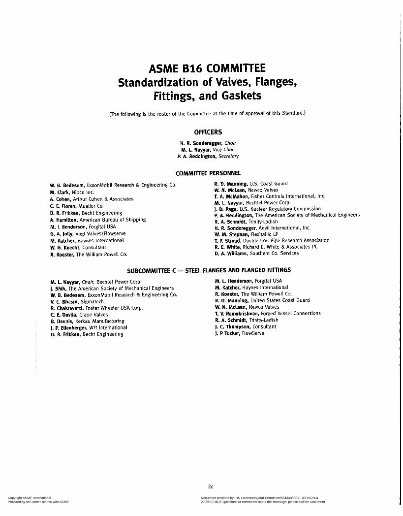
ASME B16 COMMITTEE Standardization of Valves, Flanges,
Fittings, and Gaskets (The following is the roster of the Committee at the time of approval of this Standard.)
OFFICERS H. R. Sonderegger, Chair M. L. Nayyar, Vice Chair
P. A. Reddington, 5ecretary
COMMITTEE PERSONNEL
W. B. Bedesem, ExxonMobil Research & Engineering Co. M. Clark, Nibco Inc. A. Cohen, Arthur Cohen & Associates C. E. Floren, Mueller Co. D. R. Frikken, Becht Engineering A. Hamilton, American Bureau of Shipping M. 1 Henderson, Forgital USA G. A. Jolly, Vogt Valves/Flowserve M. Katcher, Haynes International W. G. Knecht. Consultant R. Koester, The William Powell Co.
R. D. Manning, U.S. Coast Guard W. N. McLean. Newco Valves T. A. McMahon, Fisher Controls International, Inc. M. L. Nayyar, Bechtel Power Corp. J. D. Page, U.S. Nuclear Regulatory Commission P. A. Reddington, The American Society of Mechanical Engineers R. A. Schmidt, Trinity-Ladish H. R. Sonderegger, Anvil International, Inc. W. M. Stephan, Flexitallic LP T. F, Stroud, Ductile Iron Pipe Research Association R. E. White, Richard E. White & Associates PC D. A. Williams, Southern Co. Services
SUBCOMMITTEE C - STEEL FLANGES AND FLANGED FIllINGS
M. 1. Nayyar, Chair, Bechtel Power Corp. J. Shih, The American Society of Mechanical Engineers W. B. Bedesem, ExxonMobil Research & Engineering Co. V. C. Bhasin, Sigmatech R. Chakravarti, Foster Wheeler USA Corp. C. E. Davila, Crane Valves B. Dennis, Kerkau Manufacturing J. P. Ellenberger, WFI International D. R. Frikken, Becht Engineering
M. L. Henderson, Forgital USA M. Katcher, Haynes International R. Koester, The William Powell Co. R. D. Manning, United States Coast Guard W. N. Mclean, Newco Valves T. V. Ramakrishnan, Forged Vessel Connections R. A. Schmidt, Trinity-Ladish J. C. Thompson. Consultant J. P Tucker, Flowserve
ix Copyright ASME International Provided by IHS under license with ASME
Document provided by IHS Licensee=Qatar Petroleum/5943408001, 09/19/200422:36:17 MDT Questions or comments about this message: please call the DocumentPolicy Group at 303-397-2295.
--```,,`,``,,,,`,,``````,,``,`-`-`,,`,,`,`,,`---
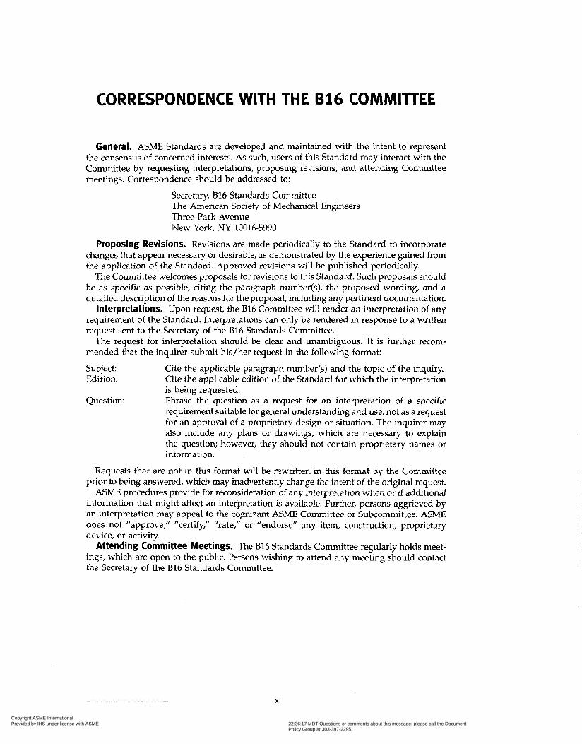
General. ASME Standards are developed and maintained with the intent to represent the consensus of concerned interests. As such, users of this Standard may interact with the Committee by requesting interpretations, proposing revisions, and attending Committee meetings. Correspondence should be addressed to:
Secretary, B16 Standards Committee The American Society of Mechanical Engineers Three Park Avenue New York, NY 10016-5990
Proposing Revisions. Revisions are made periodically to the Standard to incorporate changes that appear necessary or desirable, as demonstrated by the experience gained from the application of the Standard. Approved revisions will be published periodically.
The Committee welcomes proposals for revisions to this Standard. Such proposals should be as specific as possible, citing the paragraph number(s), the proposed wording, and a detailed description of the reasons for the proposal, including any pertinent documentation.
Interpretations. Upon request, the B16 Committee will render an interpretation of any requirement of the Standard. Interpretations can only be rendered in response to a written request sent to the Secretary of the B16 Standards Committee.
The request for interpretation should be clear and unambiguous. It is further recom- mended that the inquirer submit his/her request in the following format:
Subject: Cite the applicable paragraph number@) and the topic of the inquiry. Edition: Cite the applicable edition of the Standard for which the interpretation
is being requested. Question: Phrase the question as a request for an interpretation of a specific
requirement suitable for general understanding and use, not as a request for an approval of a proprietary design or situation. The inquirer may also include any plans or drawings, which are necessary to explain the question; however, they should not contain proprietary names or information.
Requests that are not in this format will be rewritten in this format by the Committee prior to being answered, which may inadvertently change the intent of the original request.
ACME procedures provide for reconsideration of any interpretation when or if additional information that might affect an interpretation is available. Further, persons aggrieved by an interpretation may appeal to the cognizant ASME Committee or Subcommittee. ASME does not ?approve,? ?certify,? ?rate,? or ?endorse? any item, construction, proprietary device, or activity.
Attending Committee Meetings. The 816 Standards Committee regularly holds meet- ings, which are open to the public. Persons wishing to attend any meeting should contact the Secretary of the B16 Standards Committee.
X
Copyright ASME International Provided by IHS under license with ASME
Document provided by IHS Licensee=Qatar Petroleum/5943408001, 09/19/200422:36:17 MDT Questions or comments about this message: please call the DocumentPolicy Group at 303-397-2295.
--```,,`,``,,,,`,,``````,,``,`-`-`,,`,,`,`,,`---

ASME 816.5-2003
PIPE FLANGES AND FLANGED FITTINGS
NPS 1/2 THROUGH NPS 24 METRIC/INCH STANDARD
1 SCOPE 1.1 General
(a) This Standard covers pressure-temperature rat- ings, materials, dimensions, tolerances, marking, test- ing, and methods of designating openings for pipe flanges and flanged fittings. Included are
(i) flanges with rating class designations 150, 300, 400, 600, 900, 1500, and 2500 in sizes NPS '4 through NPS 24, with requirements given in both metric and US. Customary units with diameter of bolts and flange bolt holes expressed in inch units
(2) flanged fittings with rating class designation 150 and 300 in sizes NPS '4 through NI'S 24, with require- ments given in both metric and U.S. Customary units with diameter of bolts and flange bolt holes expressed in inch units
(3) flanged fittings with rating class designation 400, 600, 900, 1500, and 2500 in sizes NPS 1/2 through NPS 24 that are acknowledged in Annex G in which only U.S. Customary units are provided
-!
(b) This Standard is limited to (i) flanges and flanged fittings made from cast or
forged materials (2) blind flanges and certain reducing flanges made
from cast, forged, or plate materials Also included in this Standard are requirements and
recommendations regarding flange bolting, flange gas- kets, and flange joints.
1.2 References Codes, standards, and specifications, containing pro-
visions to the extent referenced herein, constitute requirements of this Standard. These reference docu- ments are listed in Annex H.
1.3 Time of Purchase, Manufacture, or Installation The pressure-temperature ratings in this Standard are
applicable upon its publication to all flanges and flanged fittings within its scope which otherwise meet its requirements. For unused flanges or flanged fittings maintained in inventory, the manufacturer of the flange or flanged fittings may certify conformance to this Edi- tion provided that it can be demonstrated that all requirements of this Edition have been met. Where such
components were installed in accordance with the pres- sure-temperature ratings of an earlier edition of this Standard, those ratings are applicable except as may be governed by the applicable code or regulation.
1.4 User Accountability
This Standard cites duties and responsibilities that are to be assumed by the flange or flanged fitting user in the areas of, for example, application, installation, system hydrostatic testing, operation, and material selection.
1.5 Quality Systems
Quality System Program are described in Annex E. Requirements relating to the product manufacturer's
1.6 Relevant Units
This Standard states values in both metric and U.S. Customary units. As an exception, diameter of bolts and flange bolt holes are expressed in inch units only. These systems of units are to be regarded separately as stan- dard. Within the text, the U.S. Customary units are shown in parentheses or in separate tables. The values stated in each system are not exact equivalents; there- fore, it is required that each system of units be used independently of the other. Except for diameter of bolts and flange bolt holes, combining values from the two systems constitutes nonconformance with the Standard.
1.7 Service Conditions
Criteria for selection of materials suitable for particu- lar fluid service are not within the scope of this Standard.
1.8 Convention
For the purpose of determining conformance with this Standard, the convention for fixing significant digits where limits, maximum and minimum values are speci- fied, shall be rounded as defined in ASTM Practice E 29. This requires that an observed or calculated value shall be rounded off to the nearest unit in the last right hand digit used for expressing the limit. Decimal values and tolerances do not imply a particular method of mea- surement.
1
Copyright ASME International Provided by IHS under license with ASME
Document provided by IHS Licensee=Qatar Petroleum/5943408001, 09/19/200422:36:17 MDT Questions or comments about this message: please call the DocumentPolicy Group at 303-397-2295.
--```,,`,``,,,,`,,``````,,``,`-`-`,,`,,`,`,,`---
ASME 816.5-2003 PIPE FLANGES AND FLANGED FIllINGS
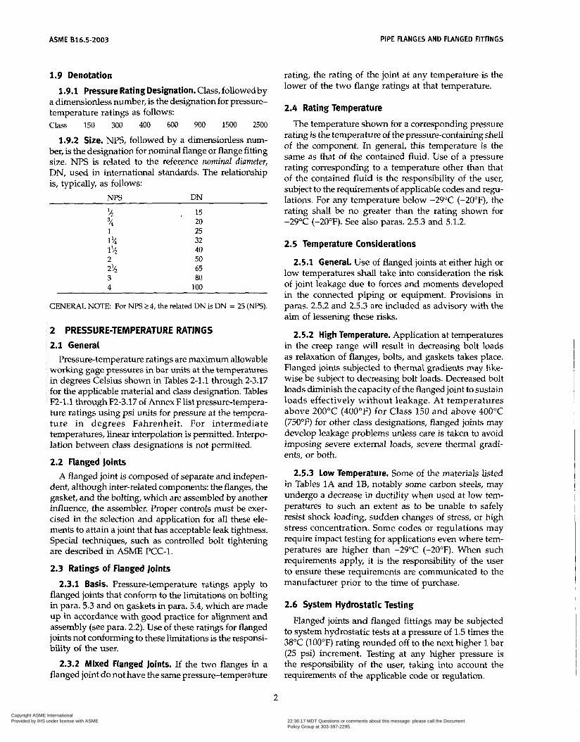
1.9 Denotation rating, the rating of the joint at any temperature is the lower of the two flange ratings at that temperature. 1.9.1 Pressure Rating Designation. Class, followed by
a dimensionless number, is the designation for pressure- temperature ratings as follows: 2.4 Rating Temperature
Class 150 300 400 600 900 15Oû 2500 The temperature shown for a corresponding pressure
1.9.2 Size. NPS, followed by a dimensionless num- ber, is the designation for nominal flange or flange fitting size. NPS is related to the reference nominal diameter, DN, used in international standards. The relationship is, typically, as follows:
m DN
% 4 1 3
1% 1% 2 2% 3 4
15 20 25 32 40 50 65 80
100
GENERAL NOTE: For N B 2 4, the related DN is DN = 25 (NPS) .
2 PRESSURE-TEMPERATURE RATINGS 2.1 General
Pressure-temperature ratings are maximum allowable working gage pressures in bar units at the temperatures in degrees Celsius shown in Tables 2-1.1 through 2-3.17 for the applicable material and class designation. Tables F2-1.1 through F2-3.17 of Annex F list pressure-tempera- ture ratings using psi units for pressure at the tempera- ture in degrees Fahrenheit. For intermediate temperatures, linear interpolation is permitted. Interpo- lation between class designations is not permitted.
2.2 Flanged Joints A flanged joint is composed of separate and indepen-
dent, although inter-related components: the flanges, the gasket, and the bolting, which are assembled by another influence, the assembler. Proper controls must be exer- cised in the selection and application for all these ele- ments to attain a joint that has acceptable leak tightness. Special techniques, such as controlled bolt tightening are described in ACME PCC-1.
2.3 Ratings of Flanged Joints
2.3.1 Basis. Pressure-temperature ratings apply to flanged joints that conform to the limitations on bolting in para. 5.3 and on gaskets in para. 5.4, which are made up in accordance with good practice for alignment and assembly (see para. 2.2). Use of these ratings for flanged joints not conforming to these limitations is the responsi- bility of the user.
2.3.2 Mixed Flanged Joints. If the two flanges in a flanged joint do not have the same pressure-temperature
rating is thé temperature of the pressure-conta&&g shell of the component. In general, this temperature is the same as that of the contained fluid. Use of a pressure rating corresponding to a temperature other than that of the contained fluid is the responsibility of the user, subject to the requirements of applicable codes and regu- lations. For any temperature below -29°C (-20"F), the rating shall be no greater than the rating shown for -29°C (-20°F). See also paras. 2.5.3 and 5.1.2.
2.5 Temperature Considerations
2.5.1 General. Use of flanged joints at either high or low temperatures shall take into consideration the risk of joint leakage due to forces and moments developed in the connected piping or equipment. Provisions in paras. 2.5.2 and 2.5.3 are included as advisory with the aim of lessening these risks.
2.5.2 High Temperature. Application at temperatures in the creep range will result in decreasing bolt loads as relaxation of flanges, bolts, and gaskets takes place. Flanged joints subjected to thermal gradients may like- wise be subject to decreasing bolt loads. Decreased bolt loads diminish the capacity of the flanged joint to sustain loads effectively without leakage. At temperatures above 200°C (400OF) for Class 150 and above 400°C (750°F) for other class designations, flanged joints may develop leakage problems unless care is taken to avoid imposing severe external loads, severe thermal gradi- ents, or both.
2.5.3 Low Temperature. Some of the materials listed in Tables 1A and lB, notably some carbon steels, may undergo a decrease in ductility when used at low tem- peratures to such an extent as to be unable to safely resist shock loading, sudden changes of stress, or high stress concentration. Some codes or regulations may require impact testing for applications even where tem- peratures are higher than -29°C (-20°F). When such requirements apply, it is the responsibility of the user to ensure these requirements are communicated to the manufacturer prior to the time of purchase.
2.6 System Hydrostatic Testing
Flanged joints and flanged fittings may be subjected to system hydrostatic tests at a pressure of 1.5 times the 38°C (100°F) rating rounded off to the next higher 1 bar (25 psi) increment. Testing at any higher pressure is the responsibility of the user, taking into account the requirements of the applicable code or regulation.
2
Copyright ASME International Provided by IHS under license with ASME
Document provided by IHS Licensee=Qatar Petroleum/5943408001, 09/19/200422:36:17 MDT Questions or comments about this message: please call the DocumentPolicy Group at 303-397-2295.
--```,,`,``,,,,`,,``````,,``,`-`-`,,`,,`,`,,`---

PIPE FLANGES AND FLANGED FITTINGS ASME 816.5-2003
2.7 Welding Neck Flanges Ratings for welding neck flanges covered by this Stan-
dard are based upon their hubs at the welding end having thickness at least equal to that calculated for pipe having 276 h4Pa (40,000 psi) specified minimum yield strength.' In order to ensure adequate flange hub thick- ness for flange sizes NI'S 2 and larger, the bore of a welding neck flange, dimension B in the various dimen- sional tables, shall not exceed B,,,, determined as follows:
where: A = tabulated hub diameter, beginning of chamfer
B,,, = maximum permissible diameter for the bore of
Co = 14.5 when p E is expressed in bar units or 1.0
pc = ceiling pressure value at 38°C (100"F), Tables B1
as listed in the dimensional tables
a welding neck flange
when pc is expressed in psi units
and B2 of Annex B
The resultant units for diameter B,,, are the same as those entered for diameter A.
The tabulated ratings for welding neck flanges are independent of components to which they may be attached and the pressure rating of the flange shall not be exceeded. Attachment welds should be made in accordance with the applicable code or regulation. See para. 6.7 and Figs. 12, 23, and 14 for weld end dimen- sional requirements.
2.8 Straight Hub Welding Flanges Straight hub welding flanges are an extension of weld-
ing neck flanges and have straight hubs of uniform thick- ness. With the exception of the following, the straight hub welding flanges shall have dimensions of the weld- ing neck flanges of the size and class set forth in Tables 8,11,14,16,18,20, and 22 (Tables F8, F11, F14, F16, F18, F20, and F22 of Annex F). See Fig. 15.
2.8.1 length Through Hub. The length through hub shall be 229 mm (9 in.) for NPS 4 and smaller and 305 mm (12 in.) for larger than NPS 4. Other lengths may be furnished by agreement between the end user and the manufacturer.
2.8.2 Bore. The bore diameter shall be equal to B dimension of the welding neck flange. Other bores may be furnished by agreement between the end user and the manufacturer. In no case shall the bore diameter exceed the bore of the same size and class lapped flange.
For flanges to be attached to high strength pipe with large inside diameters resulting from thin wall sections, see MSS SP-44.
2.8.3 Hub End. The standard flange shall be provided with square cut end. The end user may specify welding end preparation in accordance with para. 6.7.
2.9 Multiple Material Grades Material for flanges and flanged fittings may meet
the requirements of more than one specification or the requirements of more than one grade of a specification listed in Table 1A. In either case, the pressure-tempera- ture ratings for any of these specifications or grades may be used provided the material is marked in accordance with para. 4.2.8.
3 COMPONENT SIZE 3.1 Nominal Pipe Size
As applied in this Standard, the use of the phrase "nominal pipe size" or the designation NPS followed by a dimensionless number is for the purpose of pipe, flange, or flanged fitting end connection size identifica- tion. The number is not necessarily the same as the flange or flanged fitting inside diameter.
3.2 Reducing Fittings Reducing fittings shall be designated by the N P S for
the openings in the sequence indicated in the sketches of Fig. 2.
3.3 Reducing Flanges Reducing flanges shall be designated by the NPS for
each opening. See examples in Note (4) of Table 6 (Table F6 of Annex F).
4 MARKING 4.1 General
Except as modified herein, flanges and flanged fittings shall be marked as required in MSS SP-25, except as noted in para. 4.2.
4.2 Identification Markings
4.2.1 Name. The manufacturer's name or trademark shall be applied.
4.2.2 Material. Material shall be identified in the fol- lowing way:
(U) Cast flanges and flanged fittings shall be marked with the ASTM specification? grade identification sym- bol (letters and numbers), and the melt number or melt identification.
(b) Plate flanges, forged flanges, and flanged fittings shall be marked with the ASTM specification number and grade identification symbol?
An ACME Boiler and Pressure Vessel Code, Section II specifica- tion number may be substituted for an ASTM specification number provided the requirements of the ACME specification are identical to or more stringent than the ASTM specification for the Grade, Class, or type of material.
3
Copyright ASME International Provided by IHS under license with ASME
Document provided by IHS Licensee=Qatar Petroleum/5943408001, 09/19/200422:36:17 MDT Questions or comments about this message: please call the DocumentPolicy Group at 303-397-2295.
--```,,`,``,,,,`,,``````,,``,`-`-`,,`,,`,`,,`---
ASME 616.5-2003 PIPE FLANGES AND FLANGED FITTINGS
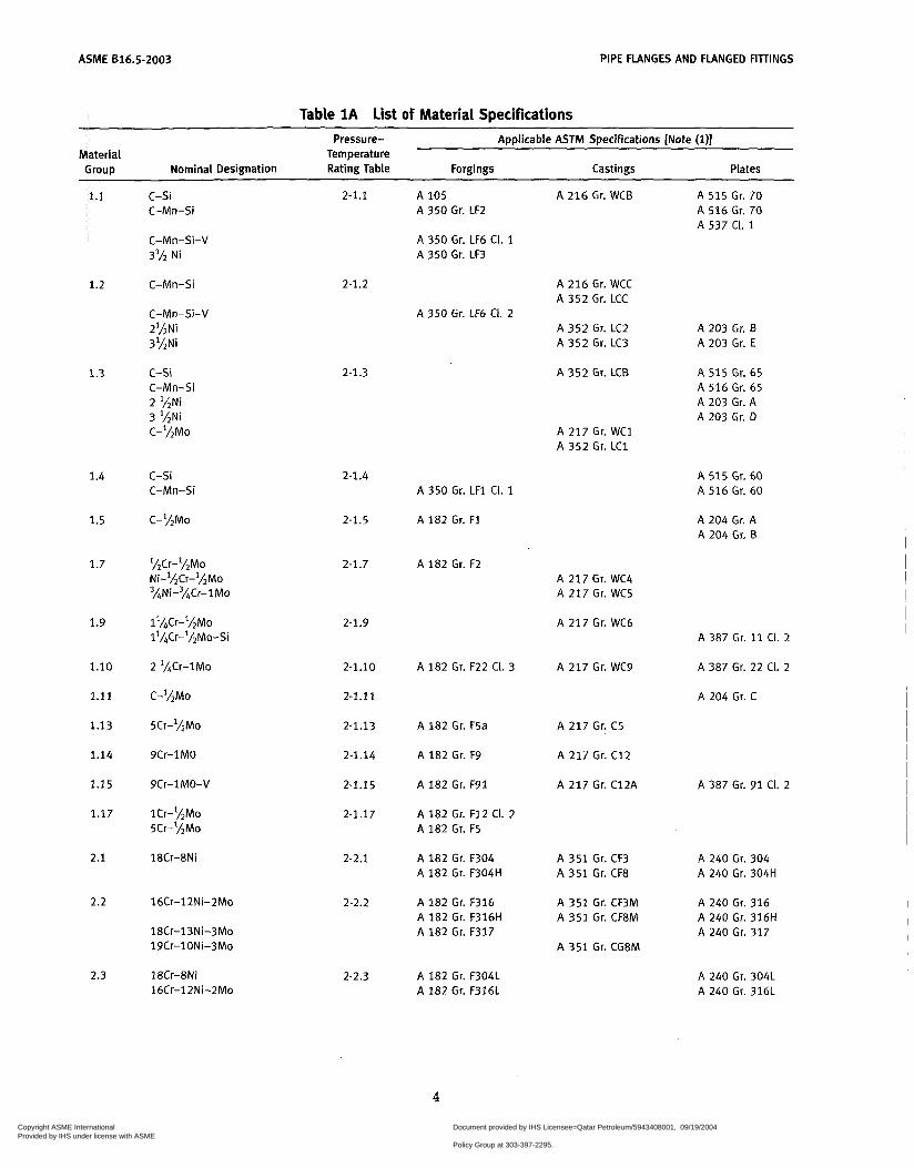
Table 1A List of Material Specifications Pressure- Applicable ASTM Specifications [Note (1)
Material Temperature Group Nominal Designation Rating Table Forgings Castings Plates
1.1
1.2
1.3
1.4
1.5
1.7
1.9
1.10
1.11
1.13
1.14
1.15
1.17
2.1
2.2
2.3
c-si C-Mn-Si
2-1.1 A 105 A 216 Gr. WCB A 515 Gr. 70 A 516 Gr. 70 A 537 CI. 1
A 350 Gr. LF2
A 350 Gr. LF6 CI. 1 A 350 Gr. LF3
C-Mn-Si-V 3'h Ni
2-1.2 A 216 Gr. WCC A 352 Gr. LCC
A 352 Gr. LC2 A 352 Gr. LC3
A 350 Gr. LF6 CI. 2
C-Mn-Si
C-Mn-Si-V 2%Ni 3'hNi
A 203 Gr. B A 203 Gr. E
2-1.3 c-si C-Mn-Si 2 %Ni 3 %Ni C-lLMo
A 352 Gr. LCB A 515 Gr. 65 A 516 Gr. 65 A 203 Gr. A A 203 Gr. D
A 217 Gr. WC1 A 352 Gr. LC1
c-si C-Mn-Si
2-1.4 A 515 Gr. 60 A 516 Gr. 60 A 350 Gr. LF1 CI. 1
A 182 Gr. F1 C-%Mo 2-1.5 A 204 Gr. A A 204 Gr. B
1LCr-1/2Mo Ni-lhCr-IhMo 'ANi-%Cr-lMo
l'LCr-'hMo 11/&r-1/2Mo-Si
2 'ACr-1Mo
C-ILMO
5Cr-lhMo
2-1.7 A 182 Gr. F2 A 217 Gr. WC4 A 217 Gr. WC5
2-1.9 A 217 Gr. WC6 A 387 Gr. 11 CI. 2
A 387 Gr. 22 CI. 2
A 204 Gr. C
2-1.10
2-1.11
2-1.13
2-1.14
2-1.15
2-1.17
A 182 Gr. F22 CI. 3 A 217 Gr. WC9
A 182 Gr. F5a A 217 Gr. C5
A 217 Gr. C12
A 217 Gr. C12A
9Cr-1MO A 182 Gr. F9
A 182 Gr. F91 A 387 Gr. 91 CI. 2 9Cr-1MO-V
lCr-%Mo 5Cr-'hMo
A 182 Gr. F12 CI. 2 A 182 Gr. F5
18Cr-8Ni 2-2.1 A 182 Gr. F304 A 182 Gr. F304H
A 351 Gr. CF3 A 351 Gr. CF8
A 240 Gr. 304 A 240 Gr. 304H
16Cr-12Ni-ZMo 2-2.2 A 182 Gr. F316 A 182 Gr. F316H A 182 Gr. F317
A 351 Gr. CF3M A 351 Gr. CF8M
A 240 Gr. 316 A 240 Gr. 316H A 240 Gr. 317 18Cr-13Ni-3Mo
19Cr-lONi-3Mo A 351 Gr. CG8M
18Cr-8Ni 16Cr-12Ni-2Mo
2-2.3 A 182 Gr. F304L A 182 Gr. F316L
A 240 Gr. 304L A 240 Gr. 316L
4
Copyright ASME International Provided by IHS under license with ASME
Document provided by IHS Licensee=Qatar Petroleum/5943408001, 09/19/200422:36:17 MDT Questions or comments about this message: please call the DocumentPolicy Group at 303-397-2295.
--```,,`,``,,,,`,,``````,,``,`-`-`,,`,,`,`,,`---
PIPE FLANGES AND FLANGED FIlTINGS ASME 816.5-2003
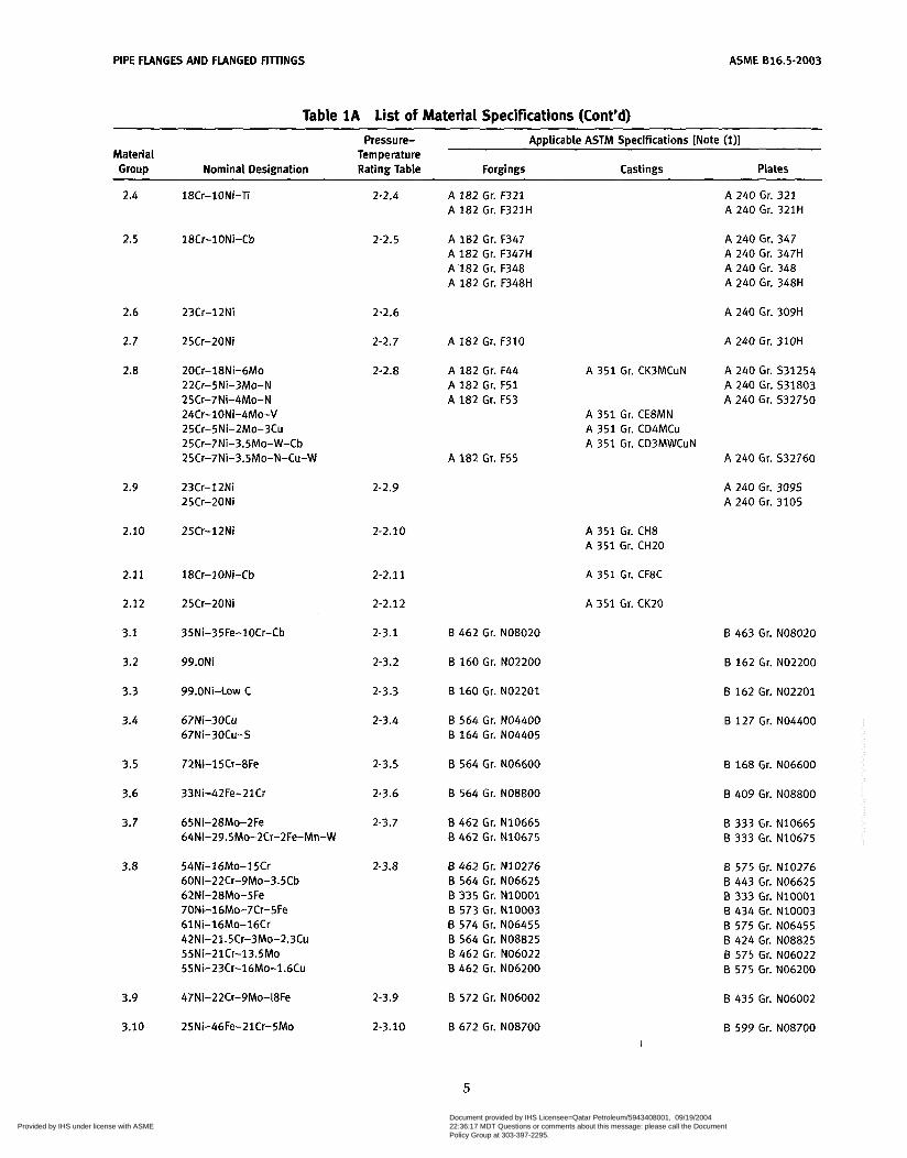
Table 1A List of Material Specifications (Cont'd)
Pressure- Applicable ASTM Specifications [Note (i)] Material Temperature Group Nominal Designation Rating Table Forgings Castings Plates
2.4
2.5
2.6
2.7
2.8
2.9
2.10
2.11
2.12
3.1
3.2
3.3
3.4
3.5
3.6
3.7
3.8
3.9
3.10
18Cr-1ONi-Ti
18Cr-1ONi-Cb
23Cr-12Ni
25Cr-20Ni
20Cr-18Ni-6Mo 22Cr-5Ni-3Mo-N 25Cr-7Ni-4Mo-N 24Cr-10Ni-4Mo-V 25Cr-5Ni-ZMo-3Cu 25Cr-7Ni-3.5Mo-W-Cb 25Cr-7Ni-3.5Mo-N-Cu-W
23Cr-12Ni 25Cr-20Ni
25Cr-12Ni
18Cr-1 ON¡-Cb
25Cr-20Ni
35Ni-35Fe-lOCr-Cb
99.ONi
99.ONi-LQW C
67Ní-30Cü 67Ni-30Cu-S
72Ni-15Cr-8Fe
33Ni-42Fe-21Cr
65Ni-28Mo-2Fe 64Ni-29.5Mo-2Cr-2Fe-Mn-W
54Ni-16Mo-15Cr 60Ni-22Cr-9Mo-3.5Cb 62Ni-28Mo-5Fe 70Ni-16Mo-7Cr-5Fe 61Ni-16Mo-16Cr 42Ni-21.5Cr-3Mo-2.3Cu 55Ni-21Cr-13.5Mo 55Ni-23Cr-16Mo-1.6Cu
2-2.4
2-2.5
2-2.6
2-2.7
2-2.8
2-2.9
2-2.10
2-2.1 1
2-2.12
2-3.1
2-3.2
2-3.3
2-3.4
2-3.5
2-3.6
2-3.7
2-3.8
2-3.9
2-3.10
A 182 Gr. F321 A 182 Gr. F321H
A 182 Gr. F347 A 182 Gr. F347H A I 8 2 Gr. F348 A 182 Gr. F348H
A 182 Gr. F310
A 182 Gr. F44 A 182 Gr. F51 A 182 Gr. F53
A 182 Gr. F55
B 462 Gr. NO8020
B 160 Gr. NO2200
B 160 Gr. NO2201
B 564 Gr. NO4400 B 164 Gr. NO4405
B 564 Gr. NO6600
B 564 Gr. NO8800
B 462 Gr. N10665 B 462 Gr. N10675
B 462 Gr. N10276 B 564 Gr. NO6625 B 335 Gr. N10001 B 573 Gr. N10003 B 574 Gr. NO6455 B 564 Gr. NO8825 B 462 Gr. NO6022 B 462 Gr. NO6200
B 572 Gr. NO6002
B 672 Gr. NO8700
A 240 Gr. 321 A 240 Gr. 321H
A 240 Gr. 347 A 240 Gr. 347H A 240 Gr. 348 A 240 Gr. 348H
A 240 Gr. 309H
A 240 Gr. 310H
A 351 Gr. CK3MCuN A 240 Gr. S31254 A 240 Gr. 531803 A 240 Gr. 532750
A 351 Gr. CE8MN A 351 Gr. CD4MCu A 351 Gr. CD3MWCuN
A 240 Gr. 532760
A 240 Gr. 3095 A 240 Gr. 310s
A 351 Gr. CHû A 351 Gr. CH20
A 351 Gr. CF8C
A 351 Gr. CK20
B 463 Gr. NO8020
B 162 Gr. NO2200
B 162 Gr. NO2201
B 127 Gr. NO4400
B 168 Gr. NO6600
B 409 Gr. NO8800
B 333 Gr. N10665 B 333 Gr. N10675
B 575 Gr. N10276 B 443 Gr. NO6625 B 333 Gr. N10001 B 434 Gr. N10003 B 575 Gr. NO6455 B 424 Gr. NO8825 B 575 Gr. NO6022 B 575 Gr. NO6200
B 435 Gr. NO6002
B 599 Gr. NO8700
5
Copyright ASME International Provided by IHS under license with ASME
Document provided by IHS Licensee=Qatar Petroleum/5943408001, 09/19/200422:36:17 MDT Questions or comments about this message: please call the DocumentPolicy Group at 303-397-2295.
--```,,`,``,,,,`,,``````,,``,`-`-`,,`,,`,`,,`---
ASME B16.5-2003 PIPE FLANGES AND FLANGED FITTINGS
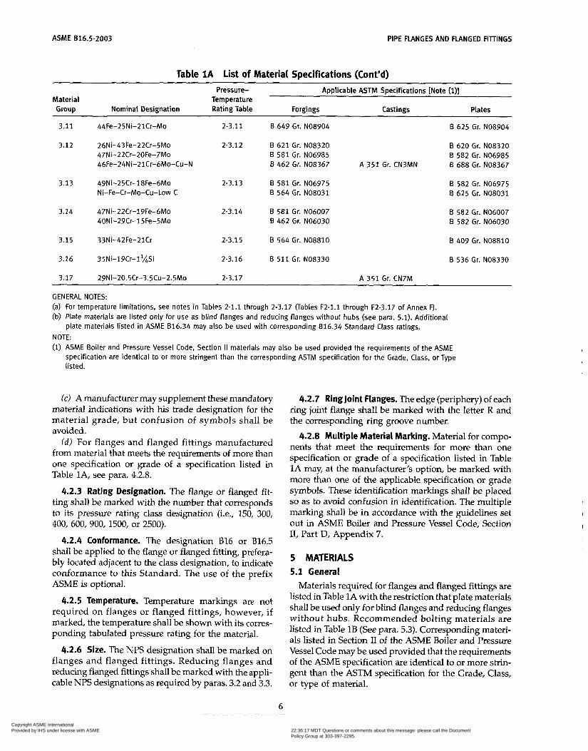
Table 1 A List of Material Specifications (Cont’d) ~~~ ~
Pressure- Applicable ASTM Specifications [Note (i)] Material Temperature Group Nominal Designation Rating Table Forgings Castings Plates
~~ ~
3.11 44Fe-25Ni-21Cr-Mo
3.12 26Ni-43Fe-22Cr-5Mo 47Ni-22Cr-20Fe-7Mo 46Fe-24Ni-21Cr-6Mo-Cu-N
3.13 49Ni-25Cr-18Fe-6Mo Ni-Fe-Cr-Mo-Cu-low C
3.14 47Ni-22Cr-19Fe-6Mo 40Ni-29Cr-15Fe-5Mo
3.15 33Ni-42Fe-21Cr
3.16 35Ni-19Cr-1 *&i
3.17 29Ni-20.5Cr-3.5Cu-2.5Mo
~ ~ ~~~~
2-3.11 B 649 Gr. NO8904
2-3.12 B 621 Gr. NO8320 B 581 Gr. NO6985 B 462 Gr. NO8367
2-3.13 B 581 Gr. NO6975 B 564 Gr. NO8031
2-3.14 B 581 Gr. NO6007 B 462 Gr. NO6030
2-3.15 B 564 Gr. NO8810
2-3.16 B 511 Gr. NO8330
2-3.17 A 351 Gr. CN7M
A 351 Gr. CN3MN
B 625 Gr. NO8904
B 620 Gr. NO8320 B 582 Gr. NO6985 B 688 Gr. NO8367
B 582 Gr. NO6975 B 625 Gr. NO8031
B 582 Gr. NO6007 B 582 Gr. NO6030
B 409 Gr. NO8810
B 536 Gr. NO8330
GENERAL NOTES: (a) For temperature limitations, see notes in Tables 2-1.1 through 2-3.17 (Tables F2-1.1 through F2-3.17 of Annex 0. (b) Plate materials are listed only for use as blind flanges and reducing flanges without hubs (see para. 5.1). Additional
plate materials listed in ASME 816.34 may also be used with corresponding B16.34 Standard Class ratings. NOTE: (1) ASME Boiler and Pressure Vessel Code, Section II materials may also be used provided the requirements of the ACME
specification are identical to or more stringent than the corresponding ASTM specification for the Grade, Class, or Type listed.
(c) A manufacturer may supplement these mandatory material indications with his trade designation for the material grade, but confusion of symbols shall be avoided.
( d ) For flanges and flanged fittings manufactured from material that meets the requirements of more than one specification or grade of a specification listed in Table lA, see para. 4.2.8.
4.2.3 Rating Designation. The flange or flanged fit- ting shall be marked with the number that corresponds to its pressure rating class designation (i.e., 150, 300, 400,600,900,1500, or 2500).
4.2.4 Conformance. The designation B16 or B16.5 shall be applied to the flange or flanged fitting, prefera- bly located adjacent to the class designation, to indicate conformance to this Standard. The use of the prefix ASME is optional.
4.2.5 Temperature. Temperature markings are not required on flanges or flanged fittings, however, if marked, the temperature shall be shown with its corres- ponding tabulated pressure rating for the material.
4.2.6 Size. The NPS designation shall be marked on flanges and flanged fittings. Reducing flanges and reducing flanged fittings shall be marked with the appli- cable NPS designations as required by paras. 3.2 and 3.3.
4.2.7 Ring Joint Flanges. The edge (periphery) of each ring joint flange shall be marked with the letter R and the corresponding ring groove number.
4.2.8 Multiple Material Marking. Material for compo- nents that meet the requirements for more than one specification or grade of a specification listed in Table 1A may, at the manufacturer’s option, be marked with more than one of the applicable specification or grade symbols. These identification markings shall be placed so as to avoid confusion in identification. The multiple marking shall be in accordance with the guidelines set out in ASME Boiler and Pressure Vessel Code, Section 11, Part D, Appendix 7.
5 MATERIALS 5.1 General
Materials required for flanges and flanged fittings are listed in Table 1A with the restriction that plate materials shall be used only for blind flanges and reducing flanges without hubs. Recommended bolting materials are listed in Table 1B (See para. 5.3). Corresponding materi- als listed in Section II of the ASME Boiler and Pressure Vessel Code may be used provided that the requirements of the ASME specification are identical to or more strin- gent than the ASTM specification for the Grade, Class, or type of material.
6
Copyright ASME International Provided by IHS under license with ASME
Document provided by IHS Licensee=Qatar Petroleum/5943408001, 09/19/200422:36:17 MDT Questions or comments about this message: please call the DocumentPolicy Group at 303-397-2295.
--```,,`,``,,,,`,,``````,,``,`-`-`,,`,,`,`,,`---
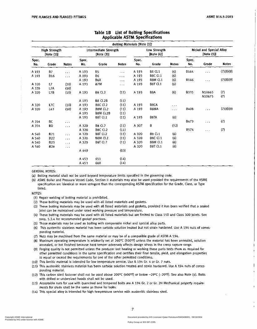
PIPE FLANGES AND FLANGED FITINGS ASME B16.5-2003
Table 1B List of Bolting Specifications Applicable ASTM Specifications
Bolting Materials [Note (111 High Strength Intermediate Strength Low Strength Nickel and Special Alloy
[Note (211 [Note (311 [Note (41 [Note (511
Spec. Spec. Spec. Spec. No. Grade Notes No. Grade Notes No. Grade Notes No. Grade Notes
A 193 A 193
A 320 A 320 A 320
A 320 A 320
A 354 A 354
A 540 A 540 A 540 A 540
87 ... A l 9 3 B16 . . . A l 9 3
A 193 L7 (10) A 193
L7B (10) A 193 L7A (1 0)
A 193 L7C (10) A 193 L4 3 (10) A 193
A 193 A 193
BC . . . BD . . . A 320
A 320 B21 . . . A 320 822 ... A 3 2 0 B23 ... A 3 2 0 824 . . .
A 449
B5 86 B6X B7M
88 C1.2
88 CI.2B B8C C1.2 B8M C1.2 B8M CI.2B B8T C1.2
B8 C1.2 B8C C1.2 B8F CI.2 B8M CI.2 B8T CI.2
. .. A l 9 3
. . . A 193
... A 193
. . . A l 9 3
(11) A 193
(1 1) (11) A 193 (11) A 193
(11) A 193
(11) A 307
(11) A 320 (11) A 320 (11) A 320
A 320
(1 1)
(1 1)
(1 3)
B8 CI.1 B8C CI.1 B8M CI.1 B8T CI . l
B8A
B8CA B8MA
B8TA
8
88 CI.1 B8C CI.1 B8M CI.1 B8T CI.1
(6) 8164 ... (7) (8) (9) (6) (6) 8166 . . . (7) (8) (9) (6)
(6) 8335 N10665 (7) N10675 (7)
A453 651 (1 4) A453 660 (14)
GENERAL NOTES: Bolting material shall not be used beyond temperature limits specified in the governing code. ASME Boiler and Pressure Vessel Code, Section Il materials may also be used provided the requirements of the ASME specification are identical or more stringent than the corresponding ASTM specification for the Grade, Class, or Type listed.
NOTES: (i) Repair welding of bolting material is prohibited. (2) These bolting materials may be used with all listed materials and gaskets. (3) These bolting materials may be used with all listed materials and gaskets, provided it has been verified that a sealed
joint can be maintained under rated working pressure and temperature. (4) These bolting materials may be used with all listed materials but are limited to Class 150 and Class 300 joints. See
para. 5.3.4 for recommended gasket practices. (5) These materials may be used as bolting with comparable nickel and special alloy parts. (6) This austenitic stainless material has been carbide solution treated but not strain hardened. Use A 194 nuts of corres-
ponding material. (7) Nuts may be machined from the same material or may be of a compatible grade of ASTM A 194. (8) Maximum operating temperature is arbitrarily set at 26OOC ( 5 O O O F ) unless the material has been annealed, solution
(9) Forging quality is not permitted unless the producer last heating or working these parts tests them as required for annealed, or hot finished because hard temper adversely affects design stress in the creep rupture range.
other permitted conditions in the same specification and certifies their final tensile, yield, and elongation properties to equal or exceed the requirements for one of the other permitted conditions.
(io) This ferritic material is intended for low temperature service. Use A 194 Gr. 4 or Gr. 7 nuts. (II) This austenitic stainless material has been carbide solution treated and strain hardened. Use A 194 nuts of corres-
(12) This carbon steel fastener shall not be used above 2OOOC (4OOOFJ or below -29OC ( - 2 O O O . See also Note (4). Bolts
(13) Acceptable nuts for use with quenched and tempered bolts are A 194 Gr. 2 or Gr. 2H Mechanical property require-
(14) This special alloy is intended for high temperature service with austenitic stainless steel.
ponding material.
with drilled or undersized heads shall not be used.
ments For studs shall be the same as those for bolts.
7
Copyright ASME International Provided by IHS under license with ASME
Document provided by IHS Licensee=Qatar Petroleum/5943408001, 09/19/200422:36:17 MDT Questions or comments about this message: please call the DocumentPolicy Group at 303-397-2295.
--```,,`,``,,,,`,,``````,,``,`-`-`,,`,,`,`,,`---
ASME 616.5-2003 PIPE FLANGES AND FLANGED FITTINGS
5.1.1 Application. Criteria for the selection of materi- als are not within the scope of this Standard. The possi- bility of material deterioration in service should be considered by the user. Carbide phase conversion to graphite and excessive oxidation of ferritic materials, susceptibility to intergranular corrosion of austenitic materials, or grain boundary attack of nickel base alloys are among those items requiring attention. A discussion of precautionary considerations can be found in ASME B31.3, Appendix F; Section II, Part D, Appendix 6; and Section III, Division 1, Appendix W of the ACME Boiler and Pressure Vessel Code.
5.1.2 Toughness. Some of the materials listed in Table 1A undergo a decrease in toughness when used at low temperatures, to the extent that Codes referencing the Standard may require impact tests for application even at temperatures higher than -7°C (+20"F). It is the responsibility of the user to assure that such testing is performed.
5.1.3 Responsibility. When service conditions dictate the implementation of special material requirements [e.g., using a Group 2 material above 538°C (1000"F)], it is the user's responsibility to so specify to the manufac- turer in order to ensure compliance with metallurgical requirements listed in the notes in Tables 2-1.1 through 2-3.17 (Tables F2-1.1 through F2-3.17 of Annex F):
5.1.4 Cast Surfaces. Cast surfaces of component pres- sure boundaries shall be in accordance with MSS SP-55 except that all Type I defects are unacceptable and defects in excess of Plates "a" and "b" for Type II through Type XII are unacceptable.
5.2 Mechanical Properties
Mechanical properties shall be obtained from test specimens that represent the final heat treated condition of the material required by the material specification.
5.3 Bolting
5.3.1 General. Bolting listed in Table 1B is recom- mended for use in flanged joints covered by this Ctan- dard. Bolting of other material may be used if permitted by the applicable code or government regulation. Bolt- ing materials are subject to the limitations given in paras. 5.3.2, 5.3.3, 5.3.4, and 5.3.5.
5.3.2 High Strength Bolting. Bolting materials having allowable stresses not less than those for ASTM A 193 Grade B7 are listed as high strength in Table 1B. These and other materials of comparable strength may be used in any flanged joint.
5.3.3 Intermediate Strength Bolting. Bolting materi- als listed as intermediate strength in Table lB, and other bolting of comparable strength, may be used in any flanged joint provided the user verifies their ability to
seat the selected gasket and maintain a sealed joint under expected operating condition.
5.3.4 Low Strength Bolting. Bolting materials having no more than 206 MPa (30 ksi) specified minimum yield strength are listed as low strength in Table 1B. These materials and others of comparable strength are to be used only in Class 150 and 300 flanged joints and only with gaskets described in para. 5.4.2. Flanged assemblies using low strength carbon steel bolts should not be used above 200°C (400°F) or below -29°C (-20°F).
5.3.5 Bolting to Gray Cast Iron Flanges. The following recommendations are made in recognition of the low ductility of gray cast iron.
(a) Alignment of flange faces is essential along with control of assembly bolt torque so as not to over-stress the cast iron flanges. Care must also be exercised to ensure that piping loads transmitted to cast iron flanges are controlled, taking into account its lack of ductility and recognizing that cast iron flanges should not be used where suddenly applied loads such as rapid pressure fluctuation may occur.
(b) Where Class 150 steel flanges are bolted to Class 125 cast iron flanges, the gaskets should be made of Annex C, Group No. Ia materials, the steel flanges should have flat faces, and
(1) low strength bolting within the limitations of para. 5.3.4 should be used with ring gaskets extending to the bolt holes, or
(2) bolting of low (para. 5.3.4), intermediate (para. 5.3.3), or high (para. 5.3.2) strength may be used with full face gaskets extending to the outside diameters of the flanges
(c) Where Class 300 steel flanges are bolted to Class 250 cast iron flanges, the gaskets should be made of Annex C, Group No. Ia materials, and
(1) low strength bolting within the limitations of para. 5.3.4 should be used with gaskets extending to the bolt holes and with the flanges having either raised or flat faces, or
(2) bolting of low (para. 5.3.4), intermediate (para. 5.3.3), or high (para. 5.3.2) strength may be used with full face gaskets extending to the outside diameters of the flanges and with both the Class 300, steel and Class 250 cast iron flanges having flat faces
5.4 Gaskets
5.4.1 General. Ring joint gasket materials shall con- form to ACME B16.20. Materials for other gaskets are described in Annex C. The user is responsible for selec- tion of gasket materials which will withstand the expected bolt loading without injurious crushing, and which are suitable for the service conditions. Particular attention should be given to gasket selection if a system hydrostatic test approaches or exceeds the test pressure specified in para. 2.6.
8
Copyright ASME International Provided by IHS under license with ASME
Document provided by IHS Licensee=Qatar Petroleum/5943408001, 09/19/200422:36:17 MDT Questions or comments about this message: please call the DocumentPolicy Group at 303-397-2295.
--```,,`,``,,,,`,,``````,,``,`-`-`,,`,,`,`,,`---

PIPE FLANGES AND FLANGED FIlTINGS ASME 016.5-2003
5.4.2 Gaskets for low Strength Bolting. If bolting listed as low strength in Table 1B is used, gaskets shown in Annex C, Table C1, Group No. Ia, are recommended.
5.4.3 Gaskets for Class 150 Flanged Joints. It is rec- ommended that only Annex C, Table C1, Group No. I gaskets be used for Class 150 flanged joints. When the ring joint or spiral wound gasket is selected, it is recom- mended that line flanges be of the welding neck or lapped joint type.
6 DIMENSIONS
6.1 Flanged Fittings Wall Thickness
6.1.1 Minimum Wall Thickness. For inspection pur- poses the minimum wall thickness t , of flanged fittings at the time of manufacture shall be as shown in Tables 9 and 12 (Tables F9 and F12 of Annex F), except as provided in para. 6.1.2. Additional metal thickness needed to withstand installation bolt-up assembly stresses, shapes other than circular, and stress concentra- tions must be determined by the manufacturer, since these factors vary widely. In particular, 45-deg laterals, true Ys, and crosses may require additional reinforce- ment to compensate for inherent weaknesses in these shapes.
6.1.2 Fitting local Areas. Local areas having less than minimum wall thickness are acceptable provided that all of the following conditions are satisfied:
(a) The area of sub-minimum thickness can be enclosed by a circle whose diameter is no greater than 0.35 Jdsm, where d is the tabulated fitting inside diameter and t , is the minimum wall thickness as shown in the tables listed in para. 6.1.1.
(b) Measured thickness is not less than 0.75 t,. (c) Enclosure circles are separated from each other by
an edge-to-edge distance of more than 1.75 &.
6.2 Fitting Center-to-Contact Surface and Center-to- End
6.2.1 Design. A principle of design in this Standard is to maintain a fixed position for the flange edge with reference to the body of the fitting. In case of raised face flanged fittings, the outside edge of the flange includes the raised face (see para. 6.4).
6.2.2 Standard Fittings. Center-to-contact surface, center-to-flange edge, and center-to end (ring joint) dimensions are shown in Tables 9 and 12 (Tables F9 and F12 of Annex F).
reducers and eccentric reducers shall be as listed for the larger opening.
6.2.4 Side Outlet Fittings. Side outlet elbows, side outlet tees, and side outlet crosses shall have all openings on intersecting centerlines, and the center-to-contact sur- face dimensions of the side outlet shall be the same as for the largest opening. Long radius elbows with one side outlet shall have the side outlet on the radial center- line of the elbow, and the center-to-contact surface dimension of the side outlet shall be the same as for the regular 90 deg elbow of the largest opening.
6.2.5 Special Degree Elbows. Special degree elbows ranging from 1 deg to 45 deg, inclusive, shall have the same center-to-contact surface dimensions as 45 deg elbows, and those over 45 deg and up to 90 deg, inclu- sive, shall have the same center-to-contact surface dimensions as 90 deg elbows. The angle designation of an elbow is its deflection from straight line flow and is also the angle between the flange faces.
6.3 Flat Face Flanges
in all classes. 6.3.1 General. This Standard permits flat face flanges
6.3.2 Conversion. A raised face may be removed from a raised face flange to convert it to a flat face flange provided that the required dimension b, shown in Fig. 7 (Fig. F7 of Annex F) is maintained.
6.3.3 Facing. The flat face flange facing finish shall be in conformance with para. 6.4.5 for the full width of the seating surface for the gasket.
6.4 Flange Facings
6.4.1 General. Figure 7 (Fig. F7. of Annex F) shows dimensional relationships for various flange types and for pipe lap facings to be used with lap joints. Table 4 (Table F4 of Annex F) lists dimensions for facings other than ring joint. Table 5 (Table F5 of Annex F) lists dimen- sions for ring joint facings. Classes 150 and 300 pipe flanges and companion flanges of fittings are regularly furnished with 2 mm (0.06 in.) raised face, which is in addition to the minimum flange thickness, 9. Classes 400,600,900,1500, and 2500 pipe flanges and companion flanges of fittings are regularly furnished with 7 mm (0.25 in.) raised face, which is in addition to the mini- mum flange thickness, q.
6.4.2 Other Than Lapped Joints. For joints other than lapped joints, the requirements of paras. 6.4.2.1 and 6.4.2.2 shall apply.
6.2.3 Reducing Fittings. Center-to-contact surface or center-to-flange edge dimensions for all openings shall be the same as those of straight size fittings of the largest opening. The contact surface-to-contact surface or flange edge-to-flange edge dimensions for all combinations of
6.4.2.1 Raised Face and Tongue Face. In the case of flanges having raised face, tongue or male face, the minimum flange thickness, lf shall be provided and then the raised face, tongue, or male face shall be added thereto.
9
Copyright ASME International Provided by IHS under license with ASME
Document provided by IHS Licensee=Qatar Petroleum/5943408001, 09/19/200422:36:17 MDT Questions or comments about this message: please call the DocumentPolicy Group at 303-397-2295.
--```,,`,``,,,,`,,``````,,``,`-`-`,,`,,`,`,,`---
ASME 816.5-2003 PIPE FLANGES AND FLANGED FIlTINGS
6.4.2.2 Grooves. For flanges that have a ring joint, groove, or female face, the minimum flange thickness shall first be provided and then sufficient thickness added thereto so that the bottom of the ring joint groove, or the contact face of the groove or female face is in the same plane as the flange edge of a full thickness flange.
6.4.3 lapped Joint Flanges. Lapped joint flanges shall be furnished with flat faces as illustrated in Tables 8, 11, 14, 16, 18, 20, and 22 (Tables F8, F11, F14, F16, F18, F20, and F22 of Annex F). Lap joint stub ends shall be in accordance with Fig. 7 (Fig. F7 of Annex F) and paras. 6.4.3.1 through 6.4.3.3.
6.4.3.1 Raised Face. The finished thickness of the lap shall be no less than nominal pipe wall thickness.
6.4.3.2 Large Male and Female. The finished height of the male face shall be the greater of the wall thickness of the pipe used or 7 mm (0.25 in.). The thickness of lap that remains after machining the female face shall be no less than the nominal wall thickness of pipe used.
6.4.3.3 Tongue and Groove. The thickness of the lap remaining after machining the tongue or groove face shall be no less than the nominal wall thickness of the pipe used.
6.4.3.4 Ring Joint. The thickness of the lap remaining after machining the ring groove shall be no less than the nominal wall thickness of pipe used.
6.4.3.5 lap Joint Facing Outside Diameters. Theout- side diameters of the lap for ring joints are shown in Table 5 (Table F5 of Annex F), dimension K. The outside diameters of laps for large female, large tongue and groove, and small tongue and groove are shown in Table 4 (Table F4 of Annex F). Small male and female facings for lapped joints are not covered by this Standard.
6.4.4 Blind Flanges. Blind flanges need not be faced in the center if, when this center part is raised, its diame- ter is at least 25 mm (1 in.) smaller than the inside diameter of fittings of the corresponding pressure class, as given in Tables 9 and 12 (Tables F9 and F12) or 25 mm (1 in.) smaller than the mating pipe inside diameter. When the center part is depressed, its diameter shall not be greater than the inside diameter of the corresponding pressure class fittings, as given in Tables 9 and 12 (Tables F9 and F12). Machining of the depressed center is not required.
6.4.5 Flange Facing Finish. Flange facing finishes shall be in accordance with paras. 6.4.5.1 through 6.4.5.3, except that other finishes may be furnished by agreement between the user and the manufacturer. The finish of the gasket contact faces shall be judged by visual comparison with Ra standards (see ASME 846.1) and not by instruments having stylus tracers and elec- tronic amplification.
6.4.5.1 Tongue and Groove and Small Male and Female. The gasket contact surface finish shall not exceed 3.2 km (125 kin.) roughness.
6.4.5.2 Ring Joint. The side wall surface finish of the gasket groove shall not exceed 1.6 km (63 pin.) roughness.
6.4.5.3 Other Flange Facings. Either a serrated con- centric or serrated spiral finish having a resultant surface finish from 3.2 to 6.3 pm (125 to 250 Fin.) average roughness shall be furnished. The cutting tool employed should have an approximate 1.5 mm (0.06 in.) or larger radius, and there should be from 1.8 grooves/mm through 2.2 grooves/mm (45 grooves/in. through 55 grooves /in.).
6.4.6 Flange Facing Finish Imperfections. Imperfec- tions in the flange facing finish shall not exceed the dimensions shown in Table 3 (Table F3 of Annex F). A distance of at least four times the maximum radial projection shall separate adjacent imperfections. A radial projection shall be measured by the difference between an outer radius and an inner radius encompassing the imperfection where the radii are struck from the center- line of the bore. Imperfections less than half the depth of the serrations shall not be considered cause for rejection. Protrusions above the serrations are not permitted.
6.5 Flange Bolt Holes
Bolt holes are in multiples of four. Bolt holes shall be equally spaced and pairs of bolt holes shall straddle fitting centerlines.
6.6 Bolting Bearing Surfaces
Flanges and flanged fittings shall have bearing sur- faces for bolting that are parallel to the flange face within 1 deg. Any back facing or spot facing shall not reduce the flange thickness, tf below the dimensions given in Tables 8, 9, 11, 12, 14, 16, 18, 20, and 22 (Tables F8, F9, F11, F12, F14, F16, F18, F20, and F22 of Annex F). Spot facing or back facing shall be in accordance with MSS SP-9.
6.7 Welding End Preparation for Welding Neck Flanges
6.7.1 Illustrations. Welding ends are illustrated in Figs. 8,9,10, 11 (Figs. F8, F9, F10, and F11 of Annex F) and Figs. 12, 13, and 14.
6.7.2 Contours. The contours of the outside of the welding neck beyond the welding groove are shown in Figs. 8 and 9 (Figs. F8 and F9 of Annex F) and Figs. 12 and 14.
6.7.3 Bores. Straight through bores shown in Figs. 8 and 9 (Figs. F8 and F9 of Annex F) are standard unless
10
Copyright ASME International Provided by IHS under license with ASME
Document provided by IHS Licensee=Qatar Petroleum/5943408001, 09/19/200422:36:17 MDT Questions or comments about this message: please call the DocumentPolicy Group at 303-397-2295.
--```,,`,``,,,,`,,``````,,``,`-`-`,,`,,`,`,,`---
PIPE FUNGES AND FLANGED FIllINGS ASME 816.5-2003
specifically ordered to suit the special conditions illus- trated in Figs. 10 and 11 (Figs. F10 and F11 of Annex F) and Figs. 13 and 14.
6.7.4 Other Welding Ends. Other welding end prepa- rations furnished by agreement of purchaser and manu- facturer do not invalidate compliance with this Standard.
6.8 Reducing Flanges
6.8.1 Drilling, Outside Diameter, Thickness, and Fac- ing Dimensions. Flange drilling, outside diameter, thick- ness, and facing are the same as those of the standard flange of the size from which the reduction is being made.
6.8.2 Hub Dimensions
6.8.2.1 Threaded, Socket Weld, and Slip-on Flanges. The hub dimension shall be at least as large as those of the standard flange of the size to which the reduction is being made. The hub may be larger or omitted as detailed in Table 6 (Table F6 of Annex F).
6.8.2.2 Welding Neck Flanges. The hub dimensions shall be the same as those of the standard flange of the size to which the reduction is being made.
6.9 Threaded Flanges
6.9.1 Thread Dimensions. Except as provided in Notes (4) and (5) of Table 4 (Table F4 of Annex F), threaded flanges shall have a taper pipe thread conform- ing to ACME B1.20.1. The thread shall be concentric with the axis of the flange opening, and variations in alignment (perpendicularity with reference to the flange face) shall not exceed 5 mm/m (0.06 in./ft).
6.9.2 Threads for Class 150 Flanges. Class 150 flanges are made without a counterbore. The threads shall be chamfered approximately to the major diameter of the thread at the back of the flange at an angle of approxi- mately 45 deg with the axis of the thread. The chamfer shall be concentric with the thread and shall be included in the measurement of the thread length.
face of the flange. See Table 6 (Table F6 of Annex F) for reducing threaded flanges.
6.9.5 Thread Gaging. The gaging notch of the work- ing gage shall come flush with the bottom of the chamfer in all threaded flanges and shall be considered as being the intersection of the chamfer cone and the pitch cone of the thread. This depth of chahfer is approximately equal to one-half the pitch of the thread. The maximum allowable thread variation is one turn large or small from the gaging notch.
6.9.6 Assembly Using Power Equipment. For ASME B1.20.1 external pipe threads, Annex A specifies the dis- tance and number of turns that external pipe threads may be made longer than regular for use with the higher pressure flanges to bring the small end of the thread close to the face of the flange when the parts are assembled by power equipment.
6.10 Flange Bolting Dimensions
6.10.1 Dimensional Standards. Stud bolts, threaded at both ends or threaded full length, or bolts may be used in flange joints. Dimensional recommendations for bolts, stud bolts, and nuts are shown in Table 1C. See para. 5.3 for bolting material recommendations.
6.10.2 Bolt lengths. Stud bolt lengths, including the height of two heavy hexagon nuts, are shown as dimen- sion L in Tables 7, 10, 13, 15, 17, 19, and 21 (Tables F7, F10, F13, F15, F17, F19, and F21 of Annex F). The tabu- lated stud bolt length L does not include the height of end points. An end point is defined as an unthreaded length, such as a chamfer, which extends beyond the thread. The method of calculating bolt lengths is explained in Annex D. The tabulated bolt lengths are reference dimensions. Users may select other bolting lengths.
6.10.3 Bolting Recommendations. For flange joints, stud bolts with a nut at each end are recommended for all applications and especially for high temperature service.
6.11 Gaskets for Line Flanges 6.9.3 Threads for Class 300 and Higher Flanges. Class
300 and higher pressure class flanges shall be made with a counterbore at the back of the flange. The threads shall
6.11.1 Ring ,oint. Ring joint gasket dimensions shall conform to ASME B16.20.
be hamfered to the diameter of the counterbore at an angle of approximately 45 deg with the axis of the threads. The counterbore and chamfer shall be concen- tric with the thread.
6.11.2 Contact Width. For flanges having large or small tongue-and-groove faces, all gaskets, except solid flat metal gaskets, shall cover the bottom of the groove with minimum clearance. [See para. 7.3(a) for tolerance applicable to groove.] Solid flaimetal gaskets shall have contact width not greater than for Annex C, Group III gaskets.
6’9’4 Reducing Thread length’ The minimum length of effective thread in reducing flanges shall be at least equal to dimension T of the corresponding class of threáded flange as shown in Tables 8; 9, 11,12, 14, 16,18,20, and 22 (Tables F8, F9, F11, F12, F14, F16, F18, F20, and F22). Threads do not necessarily extend to the
6.11.3 Bearing Surface. For flanges with small male- and-female face, care must be taken to assure that ade- quate bearing surface is provided for the gaskets. In
11 Copyright ASME International Provided by IHS under license with ASME
Document provided by IHS Licensee=Qatar Petroleum/5943408001, 09/19/200422:36:17 MDT Questions or comments about this message: please call the DocumentPolicy Group at 303-397-2295.
--```,,`,``,,,,`,,``````,,``,`-`-`,,`,,`,`,,`---
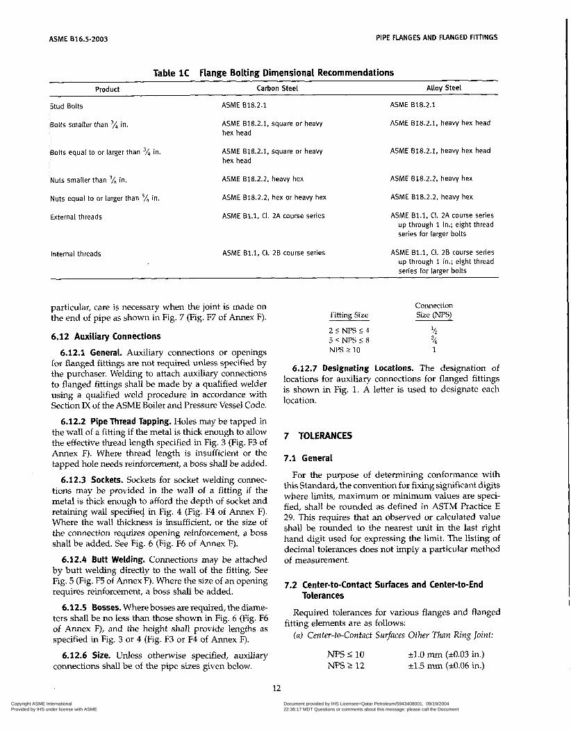
ASME 616.5-2003 PIPE FLANGES AND FLANGED FIllINGS
Table 1C Flange Bolting Dimensional Recommendations Product Carbon Steel ~ i l o y Steel
Stud Bolts ASME 818.2.1 ASME 818.2.1
Bolts smaller than 'A in.
Bolts equal to or larger than 'A in.
ASME 818.2.1, square or heavy hex head
ASME 618.2.1, square or heavy hex head
ASME 618.2.1, heavy hex head
ASME B18.2.1, heavy hex head
Nuts smaller than 'A in.
Nuts equal to or larger than 'A in.
ASME 618.2.2, heavy hex
ASME B18.2.2, hex or heavy hex
ASME 818.2.2, heavy hex
ASME 818.2.2, heavy hex
External threads
internal threads
ASME B1.1, Ci. 2A course series
ASME B1.l, CI. 2B course series
ASME B1.l, CI. 2A course series up through 1 in.; eight thread series for larger bolts
ASME B1.l, CI. 28 course series up through 1 in.; eight thread series for larger bolts
particular, care is necessary when the joint is made on the end of pipe as shown in Fig. 7 (Fig. F7 of Annex F).
6.12 Auxiliary Connections
6.12.1 General. Auxiliary connections or openings for flanged fittings are not required unless specified by the purchaser. Welding to attach auxiliary connections to flanged fittings shall be made by a qualified welder using a qualified weld procedure in accordance with Section IX of the ASME Boiler and Pressure Vessel Code.
6.12.2 Pipe Thread Tapping. Holes may be tapped in the wall of a fitting if the metal is thick enough to allow the effective thread length specified in Fig. 3 (Fig. F3 of Annex F). Where thread length is insufficient or the tapped hole needs reinforcement, a boss shall be added.
6.12.3 Sockets. Sockets for socket welding connec- tions may be provided in the wall of a fitting if the metal is thick enough to afford the depth of socket and retaining wall specified in Fig. 4 (Fig. F4 of Annex F). Where the wall thickness is insufficient, or the size of the connection requires opening reinforcement, a boss shall be added. See Fig. 6 (Fig. F6 of Annex F).
6.12.4 Butt Welding. Connections may be attached by butt welding directly to the wall of the fitting. See Fig. 5 (Fig. F5 of Annex F). Where the size of an opening requires reinforcement, a boss shall be added.
6.12.5 Bosses. Where bosses are required, the diame- ters shall be no less than those shown in Fig. 6 (Fig. F6 of Annex F), and the height shall provide lengths as specified in Fig. 3 or 4 (Fig. F3 or F4 of Annex F).
6.1 2.6 Size. Unless otherwise specified, auxiliary connections shall be of the pipe sizes given below.
Connection Fitting Size Size ( N E )
2 I NPS I 4
NPS 2 10 1
% 5 1 N P S I 8 %
6.12.7 Designating Locations. The designation of locations for auxiliary connections for flanged fittings is shown in Fig. 1. A letter is used to designate each location.
7 TOLERANCES
7.1 General
For the purpose of determining conformance with this Standard, the convention for fixing significant digits where limits, maximum or minimum values are speci- fied, shall be rounded as defined in ASTM Practice E 29. This requires that an observed or calculated value shall be rounded to the nearest unit in the last right hand digit used for expressing the limit. The listing of decimal tolerances does not imply a particular method of measurement.
7.2 Center-to-Contact Surfaces and Center-to-End Tolerances
Required tolerances for various flanges and flanged
( a ) Center-to-Contact Surfaces Other Than Ring Joint: fitting elements are as follows:
NPS I 10 NPS 2 12
11.0 mm (k0.03 in.) k1.5 mm (k0.06 in.)
12
Copyright ASME International Provided by IHS under license with ASME
Document provided by IHS Licensee=Qatar Petroleum/5943408001, 09/19/200422:36:17 MDT Questions or comments about this message: please call the DocumentPolicy Group at 303-397-2295.
--```,,`,``,,,,`,,``````,,``,`-`-`,,`,,`,`,,`---
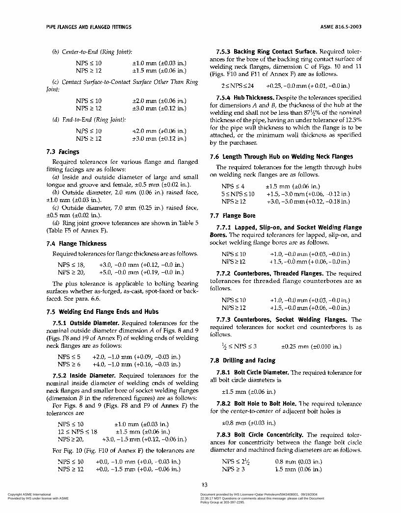
PIPE FLANGES AND FLANGED FIlTINGS ASME B16.5-2003
(b) Center-to-End (Ring Joint):
NPS I 10 NPS 2 12
k1.0 mm (10.03 in.) k1.5 mm (20.06 in.)
(c) Contact Surface-to-Contact Surface Other Than Ring Joint:
NPS I 10 NPS 2 12
(d) End-to-End (Ring Joint):
NPS I 10 NPS 2 12
k2.0 mm (k0.06 in.) 13.0 mm (k0.12 in.)
12.0 mm (k0.06 in.) 13.0 mm (k0.12 in.)
7.3 Facings
fitting facings are as follows:
tongue and groove and female, k0.5 mm (10.02 in.).
k1.0 mm (10.03 in.).
k0.5 mm (k0.02 in.).
(Table F5 of Annex F).
7.4 Flange Thickness
Required tolerances for various flange and flanged
(a) Inside and outside diameter of large and small
(b) Outside diameter, 2.0 mm (0.06 in.) raised face,
(c) Outside diameter, 7.0 mm (0.25 in.) raised face,
(d) Ring joint groove tolerances are shown in Table 5
Required tolerances for flange thickness are as follows.
NPS I18, +3.0, -0.0 (+0.12, -0.0 in.) NPS 2 20, +5.0, -0.0 mm (+0.19, -0.0 in.)
The plus tolerance is applicable to bolting bearing surfaces whether as-forged, as-cast, spot-faced or back- faced. See para. 6.6.
7.5 Welding End Flange Ends and Hubs
7.5.1 Outside Diameter. Required tolerances for the nominal outside diameter dimension A of Figs. 8 and 9 (Figs. F8 and F9 of Annex F) of welding ends of welding neck flanges are as follows:
NPS 5 5 NPS L 6
+2.0, -1.0 inïíì (+0.09, -0.03 in.) +4.0, -1.0 íììin (+0.16, -0.03 in.)
7.5.2 Inside Diameter. Required tolerances for the nominal inside diameter of welding ends of welding neck flanges and smaller bore of socket welding flanges (dimension B in the referenced figures) are as follows:
For Figs. 8 and 9 (Figs. F8 and F9 of Annex F) the tolerances are
NPS 2 10 12 I NPS I 18
r l . O mm (k0.03 in.) r1.5 mm (10.06 in.)
NPS 2 20, +3.0, -1.5 mììì (+0.12, -0.06 in.)
For Fig. 10 (Fig. F10 of Annex F) the tolerances are
NPS 2 10 NPS 2 12
+O.O, -1.0 11uï1 (+O.O, -0.03 in.) +O.O, -1.5 ï ï ì i ~ ~ (+O.O, -0.06 in.)
7.5.3 Backing Ring Contact Surface. Required toler- ances for the bore of the backing ring contact surface of welding neck flanges, dimension C of Figs. 10 and 11 (Figs. F10 and F11 of Annex F) are as follows.
2INPS224 +0.25,-0.0mm(+0.01,-0.0in.)
7.5.4 Hub Thickness. Despite the tolerances specified for dimensions A and B, the thickness of the hub at the welding end shall not be less than 87'/2% of the nominal thickness of the pipe, having an under tolerance of 12.5% for the pipe wall thickness to which the flange is to be attached, or the minimum wall thickness as specified by the purchaser.
7.6 length Through Hub on Welding Neck Flanges
on welding neck flanges are as follows.
11.5 mm (r10.06 in.)
+3.0, -5.0 mm (+0.12, -0.18 in.)
The required tolerances for the length through hubs
NPS I 4
NPS 2 12 5INPS510 +1.5,-3.0mm(+0.06,-0.12in.)
7.7 Flange Bore
7.7.1 lapped, Slip-on, and Socket Welding Flange Bores. The required tolerances for lapped, slip-on, and socket welding flange bores are as follows.
NPS 2 10 NPS 2 12
+1.0, -0.0 mm (+0.03, -0.0 in.) +1.5, -0.Ó mm (+ 0.06, -0.0 in.)
7.7.2 Counterbores, Threaded Flanges. The required tolerances for threaded flange counterbores are as follows.
NPS I 10 NPS 2 12
+ L O , -0.0 mm (+0.03, -0.0 in.) +1.5, -0.0 mm (+0.06, -0.0 in.)
7.7.3 Counterbores, Socket Welding Flanges. The required tolerances for socket end counterbores is as follows.
1 / ,<NPSI3 10.25 mm (-tO.OlO in.)
7.8 Drilling and Facing
all bolt circle diameters is 7.8.1 Bolt Circle Diameter. The required tolerance for
k1.5 mm (10.06 in.)
7.8.2 Bolt Hole to Bolt Hole. The required tolerance for the center-to-center of adjacent bolt holes is
k0.8 mm (10.03 in.)
7.8.3 Bolt Circle Concentricity. The required toler- ances for concentricity between the flange bolt circle diameter and machined facing diameters are as follows.
NPS S 2'4 NPS 2 3
0.8 mm (0.03 in.) 1.5 mm (0.06 in.)
13 Copyright ASME International Provided by IHS under license with ASME
Document provided by IHS Licensee=Qatar Petroleum/5943408001, 09/19/200422:36:17 MDT Questions or comments about this message: please call the DocumentPolicy Group at 303-397-2295.
--```,,`,``,,,,`,,``````,,``,`-`-`,,`,,`,`,,`---
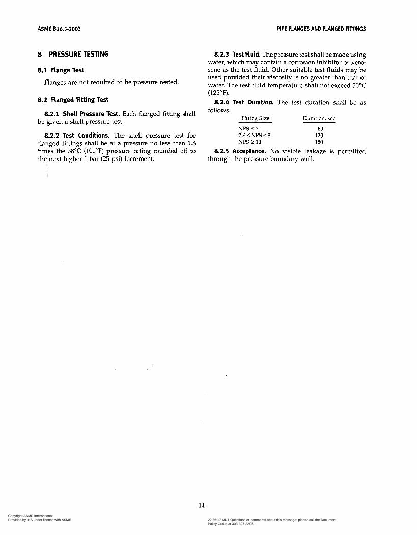
ASME 816.5-2003 PIPE FLANGES AND FLANGED FITTINGS
8 PRESSURE TESTING
8.1 Flange Test
Flanges are not required to be pressure tested.
8.2 Flanged Fitting Test
8.2.1 Shell Pressure Test. Each flanged fitting shall
8.2.2 Test Conditions. The shell pressure test for flanged fittings shall be at a pressure no less than 1.5 times the 38°C (100°F) pressure rating rounded off to the next higher 1 bar (25 psi) increment.
be given a shell pressure test.
8.2.3 Test Fluid. The pressure test shall be made using water, which may contain a corrosion inhibitor or kero- sene as the test fluid. Other suitable test fluids may be used provided their viscosity is no greater than that of water. The test fluid temperature shall not exceed 50°C (125°F).
8.2.4 Test Duration. The test duration shall be as follows.
Fitting Size Duration, sec
NPS I 2 60
NPS 2 10 180 2?4I NI'S I 8 120
8.2.5 Acceptance. No visible leakage is permitted through the pressure boundary wall.
14 Copyright ASME International Provided by IHS under license with ASME
Document provided by IHS Licensee=Qatar Petroleum/5943408001, 09/19/200422:36:17 MDT Questions or comments about this message: please call the DocumentPolicy Group at 303-397-2295.
--```,,`,``,,,,`,,``````,,``,`-`-`,,`,,`,`,,`---
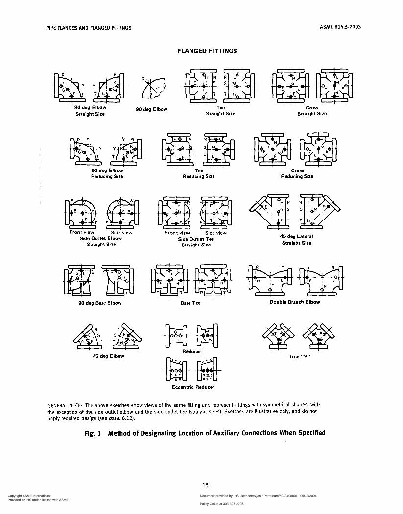
PIPE FLANGES AND FLANGED FilliNGS
FLANGED FITTINGS
ASME 816.5-2003
90 deg Elbow 90 deg Elbow Tee Straight Size Straight Size
90 deg Elbow Reducing Size
Front view Side view Side Outlet Elbow
Straight Size
90 deg Base Elbow
45 deg Elbow
T M Reducing Size
Front view Side view Side Outlet Tee
Straight Size
Base
Reducer
Cross Straight Size
Cross Reducing Size
Cross Reducing Size
45 deg Lateral Straight Size
Double Branch Elbow
True "Y"
Eccentric Reducer
GENERAL NOTE: The above sketches show views of the same fitting and represent fittings with symmetrical shapes, with the exception of the side outlet elbow and the side outlet tee (straight sizes). Sketches are illustrative only, and do not imply required design (see para. 6.12).
Fig. 1 Method of Designating location of Auxiliary Connections When Specified
15 Copyright ASME International Provided by IHS under license with ASME
Document provided by IHS Licensee=Qatar Petroleum/5943408001, 09/19/200422:36:17 MDT Questions or comments about this message: please call the DocumentPolicy Group at 303-397-2295.
--```,,`,``,,,,`,,``````,,``,`-`-`,,`,,`,`,,`---

A S M E 616.5-2003 PIPE FLANGES A N D FLANGED FITTINGS
FLANGED FITTINGS
Reducing Tees [mc ;mc A A
Reducing on Reducing on One Run One Run and Outlet
B
A Reducing on
Outlet
B
A Reducing on One Outlet
B
A Reducing on
Branch
Reducing Crosses
A
B -0
-c
D
A Reducing on Reducing on Both Outlets One Run and Outlet
Reducing Laterals
P D A A
Reducing on One Run
Reducing on One Run and Branch
B
A Reducing on Both Runs (Bullhead)
B
A Reducing on One Run
and Both Outlets
A
True "Y"
Side Outlet Tee Double Branch Side Outlet Elbow
A A C A A Right Hand Lef t Hand Right Hand Left Hand
GENERAL NOTES: (a) The largest opening establishes the basic size of a reducing fitting. The largest opening is named first, except that for
bull head tees, which are reducing on both runs and for double branch elbows where both branches are reducing, the oulet is the largest opening and named last in both cases.
letters A, B, C, and D. In designating the outlets of side outlet reducing fittings, the side outlet is named last, and in the case of the cross, which is not shown, the side outlet is designated by the Letter E.
(b) In designating the openings of reducing fittings, they should be read in the order indicated by the sequence of the
(c) Sketches are illustrative only, and do not imply required design. (See para. 3.2).
Fig. 2 Method of Designating Outlets of Reducing Fittings in Specifications
16
Copyright ASME International Provided by IHS under license with ASME
Document provided by IHS Licensee=Qatar Petroleum/5943408001, 09/19/200422:36:17 MDT Questions or comments about this message: please call the DocumentPolicy Group at 303-397-2295.
--```,,`,``,,,,`,,``````,,``,`-`-`,,`,,`,`,,`---

PIPE FLANGES AND FLANGED F I l T N G S ASME 816.5-2003
Connection
Thread length T, Size, NPS '/á lh 3/4 1 1% 1% 2
mm [Note (111 10.5 13.5 14.0 17.5 18.1 18.3 19.4
GENERAL NOTE: See paras. 6.12.2, 6.12.5, and 6.12.6. NOTE: (i) In no case shall the effective length of thread T be less than that
shown in Table above. These lengths are equal to the effective thread length of external pipe threads (ASME B1.20.1).
Fig. 3 Thread Length for Connection Tapping
GENERAL NOTE: See paras. 6.12.4 and 6.12.5.
Fig. 5 Butt Welding for Connections
Connection Size,
Minimum boss N PS 'A3 % YI 1 1% 1% 2
diameter/, mm 31.8 38.1 44.5 53.8 63.5 69.8 85.8
Connection
Minimum diam- eter of socket A, mm 17.5 21.8 26.9 33.8 42.7 48.8 61.2
Minimum depth
Size, NPS 'h % % 1 1'/4 1% 2
6, mm 4.8 4.8 6.4 6.4 6.4 6.4 7.9
GENERAL NOTES: (a) See para. 6.12.5. (b) Dimensions are in millimeters. For dimensions in inches, refer to
Annex F, Figs. F3, F4, F5, and F6.
Fig. 6 Bosses for Connections
GENERAL NOTE: See paras. 6.12.3, 6.12.5, and 6.12.6.
Fig. 4 Socket Welding for Connections
17 Copyright ASME International Provided by IHS under license with ASME
Document provided by IHS Licensee=Qatar Petroleum/5943408001, 09/19/200422:36:17 MDT Questions or comments about this message: please call the DocumentPolicy Group at 303-397-2295.
--```,,`,``,,,,`,,``````,,``,`-`-`,,`,,`,`,,`---

ASME 816.5-2003 PIPE FLANGES AND FLANGED FITTINGS
END FLANGE FACINGS Flange Thickness and Center-to-End Dimensions
Classes 150 through 2500
AA, BB, CC, etc. INo tes i l ) , í2)l j
regularly furnished on Classes 150 and R 300 unless otherwise
2 mm raised face
ordered l l n 7mm-i I+ I I I
regularly furnished on Classes 400 and higher unless otherwise ordered
7 mm raised face
(Note i4)l
Large or small male face
l
Small Large female female
Large or small female face (Note (4i1
Small male face (on end of pipe)
S Note (3) '
AA, 66, CC, etc. [Notes ( I ) , (2i1
Small female face (on end of pipe)
7 mm
Large or small tongue face
tongue tongue and I I large
F T I T dl-! K(Note (411 y
Small Larae Srnail ' - I I groove groÕve and I
larae
It- HH, JJ, KK, etc.- [Notes il), (211
Fig. 7 End Flange Facings and Their Relationship to Flange Thickness and Center-to-End and End-to-End Dimensions
18 Copyright ASME International Provided by IHS under license with ASME
Document provided by IHS Licensee=Qatar Petroleum/5943408001, 09/19/200422:36:17 MDT Questions or comments about this message: please call the DocumentPolicy Group at 303-397-2295.
--```,,`,``,,,,`,,``````,,``,`-`-`,,`,,`,`,,`---

PIPE FLANGES AND FLANGED FITINGS ASME 816.5-2003
END FLANGE FACINGS Flange Thickness and End-to-End Dimensions
Lapped Joints
Raised face
Ring joint
K [Note (711
P
GENERAL NOTES: (a) Large male and female faces and large tongue and groove are
not applicable to Class 150 because of potential dimensional conflicts.
(b) Dimensions are in millimeters. For dimensions in inches, refer to Annex F, Fig. F7.
(c) See Table 4 for dimensions of facings (other than ring joint) and Table 5 for ring joint facing.
NOTES: See paras. 6.2 and 6.4. See Tables 7 through 22. For small male and female joints, care should be taken in the use of these dimensions to insure that the inside diameter of fitting or pipe is small enough to permit sufficient bearing surface to prevent crushing of the gasket (See Table 4.). This applies particularly on lines where the joint is made on the end of the pipe. Threaded companion flanges for small male and female joints are furnished with plain face and are threaded with American National Standard Locknut Thread (NPSL). See Table 4. See Table 5 . See para. 6.4.3. See para. 6.4.3.5 and Table 5.
Fig. 7 End Flange Facings and Their Relationship to Flange Thickness and Center-to-End
and End-to-End Dimensions (Cont’d)
19
Copyright ASME International Provided by IHS under license with ASME
Document provided by IHS Licensee=Qatar Petroleum/5943408001, 09/19/200422:36:17 MDT Questions or comments about this message: please call the DocumentPolicy Group at 303-397-2295.
--```,,`,``,,,,`,,``````,,``,`-`-`,,`,,`,`,,`---
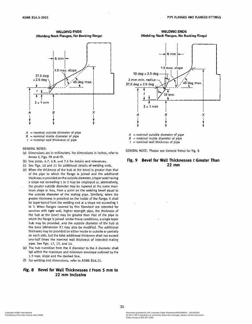
ASME 816.5-2003 PIPE FLANGES AND FLANGED FITTINGS
WELDING ENDS (Welding Neck Flanges, No Backing Rings)
I 4 t t
A B X
i A = nominal outside diameter of pipe B = nominal inside diameter of pipe t = nominal wall thickness of pipe
i
GENERAL NOTES: (a) Dimensions are in millimeters. For dimensions in inches, refer to
Annex F, Figs. F8 and F9. (b) See paras. 6.7, 6.8, and 7.4 for details and tolerances. (c) See Figs. 10 and 11 for additional details of welding ends. (d) When the thickness of the hub at the bevel is greater than that
of the pipe to which the flange is joined and the additional thickness is provided on the outside diameter, a taperweld having a slope not exceeding 1 to 3 may be employed or, alternatively, the greater outside diameter may be tapered at the same maxi- mum slope or less, from a point on the welding bevel equal to the outside diameter of the mating pipe. Similarly, when the greater thickness is provided on the inside of the flange, it shall be taper-bored from the welding end at a slope not exceeding 1 to 3. When flanges covered by this Standard are intended for services with light wall, higher strength pipe, the thickness of the hub at the bevel may be greater than that of the pipe to which the flange is joined. Under these conditions, a single taper hub may be provided, and the outside diameter of the hub at the base (dimension X ) may also be modified. The additional thickness may be provided on either inside or outside or partially on each side, but the total additional thickness shall not exceed one-half times the nominal wall thickness of intended mating pipe. See Figs. 12, 13, and 14.
(e) The hub transition from the A diameter to the X diameter shall fall within the maximum and minimum envelope outlined by the 1:3 max. slope and the dashed line.
(9 For welding end dimensions, refer to ASME 816.25.
WELDING ENDS (Welding Neck Flanges, No Backing Rings)
10 deg f 2.5 deg - 3 mm min. radius
37.5 deg 2 2.5 deg 37.5
2 + ' I mrn I A 6
i A = nominal outside diameter of pipe B = nominal inside diameter of pipe t = nominal wall thickness of pipe
GENERAL NOTE: Please see General Notes for Fig. 8.
Fig. 9 Bevel for Wall Thicknesses t Greater Than 22 mm
Fig. 8 Bevel for Wall Thicknesses t From 5 m m to 22 mm Inclusive
20 Copyright ASME International Provided by IHS under license with ASME
Document provided by IHS Licensee=Qatar Petroleum/5943408001, 09/19/200422:36:17 MDT Questions or comments about this message: please call the DocumentPolicy Group at 303-397-2295.
--```,,`,``,,,,`,,``````,,``,`-`-`,,`,,`,`,,`---

ASME 816.5-2003 PIPE FLANGES AND FLANGED FIllINGS
WELDING ENDS (Welding Neck Flanges)
WELDING ENDS (Welding Neck Flanges)
3.0 mm min. radius
13 mm min. [Note ( I ) ]
A = nominal outside diameter of welding end, mm 6 = nominal inside diameter of pipe (= A - 2t), mm C = A - 0.79 - 1.75t - 0.25, mm t = nominal wall thickness of pipe, mm
0.79 mm = minus tolerance on outside diameter of pipe to ASTM A 106, etc.
etc.) multiplied by two to convert into terms of diameter
1.75t = 87%% of nominal wall (permitted by ASTM A 106,
0.25 mm = plus tolerance on diameter C, mm. See para. 7.5.3.
GENERAL NOTES: (a) Dimensions are in millimeters. For dimensions in inches, refer to
Annex F, Figs. F10 and F11. (b) See paras. 6.7, 6.8, and 7.5 for details and tolerances. (c) See Figs. 8 and 9 for welding end details of welding neck flanges. (d) For dimensions, see ASME 816.25. NOTE: (1) 1 3 mm depth based on use of 19mm wide backing ring.
Fig. 10 Inside Contour for Use With Rectangular Backing Ring
A = nominal outside diameter of welding end, mm 6 = nominal inside diameter of pipe = A - 2t, mm C = A - 0.79 - 1 .73 - 0.25, mm t = nominal wall thickness of pipe, mm
0.79 mm = minus tolerance on outside diameter of pipe to ASTM A 106, etc.
etc.) multiplied by two to convert into terms of diameter
1.7% = 87%% of nominal wall (permitted by ASTM A 106,
0.25 mm = plus tolerance on diameter C, mm. See para. 7.5.3.
GENERAL NOTES: (a) Dimensions are in millimeters. For dimensions in inches, refer to
Annex F, Fig. F11. (b) See paras. 6.7, 6.8, and 7.5 for details and tolerances. (c) See Figs. 8 and 9 for welding end details of welding neck Flanges. (d) 3 mm depth based on use of 19-mm wide backing ring. (e) For dimensions, see ASME 616.25.
Fig. il Inside Contour for Use With Taper Backing Ring
21
Copyright ASME International Provided by IHS under license with ASME
Document provided by IHS Licensee=Qatar Petroleum/5943408001, 09/19/200422:36:17 MDT Questions or comments about this message: please call the DocumentPolicy Group at 303-397-2295.
--```,,`,``,,,,`,,``````,,``,`-`-`,,`,,`,`,,`---

ASME 616.5-2003 PIPE FLANGES AND FLANGED FITTINGS
WELDING ENDS (Welding Neck Flanges)
ADDITIONAL THICKNESS FOR WELDING TO HIGHER STRENGTH PIPE
18 deg max. (1 :3) 14 dea min. (1 :4)
GENERAL NOTES: (a) When the materials joined have equal minimum specified yield
strength, there shall be no restriction on the minimum slope. (b) Neither t,, tZ, nor their sum t, + t2 shall exceed 0.5t. (c) When the minimum specified yield strengths of the sections to
be joined are unequal, the value of tI, shall at least equal the mating wall thickness times the ratio of minimum specified yield strength of the pipe to minimum specified yield strength of the flange.
(d) Welding shall be in accordance with the applicable code.
Fig. 12 Bevel for Outside Thickness
WELDING ENDS (Welding Neck Flanges1
ADDITIONAL THICKNESS FOR WELDING TO HIGHER STRENGTH PIPE
WELDING ENDS (Welding Neck Flanges)
ADDITIONAL THICKNESS FOR WELDING TO HIGHER STRENGTH PIPE
18 deg max. (1 :31 14 deg min. (1 :4!
GENERAL NOTES: (a) When the materials joined have equal minimum specified yield
(b) Neither tl, t2, nor their sum tl + t2 shall exceed 0 3 . (c) When the minimum specified yield strengths of the sections to
be joined are unequal, the value of t D shall at least equal times the ratio of minimum specified yield strength of the pipe to minimum specified yield strength of the flange.
strength, there shall be no restriction on the minimum slope.
(d) Welding shall be in accordance with the applicable code.
Fig. 14 Bevel for Combined Thickness
pJtt& Note (4)
GENERAL NOTES: (a) When the materials joined have equal minimum specified yield
(b) Neither tl, t2, nor their sum tl + t2 shall exceed 0.5t. (c) When the minimum specified yield strengths of the sections to
be joined are unequal, the value of t D shall at least equal times the ratio of minimum specified yield strength of the pipe to minimurn specified yield strength of the flange.
strength, there shall be no restriction on the minimum slope.
(d) Welding shall be in accordance with the applicable code.
GENERAL NOTES: (a) O = Outside diameter of flange. See para. 2.8. (b) tf = Minimum thickness of flange. See para. 2.8. NOTES: (1) X = Diameter of hub. See para. 2.8. (2) Y = Length through hub. See para. 2.8.1, (3) B = Bore. See para. 2.8.2. (4) Hub end. See para. 2.8.3.
Fig. 13 Bevel for Inside Thickness Fig. 1 5 Straight Hub Welding Flanges
22 Copyright ASME International Provided by IHS under license with ASME
Document provided by IHS Licensee=Qatar Petroleum/5943408001, 09/19/200422:36:17 MDT Questions or comments about this message: please call the DocumentPolicy Group at 303-397-2295.
--```,,`,``,,,,`,,``````,,``,`-`-`,,`,,`,`,,`---
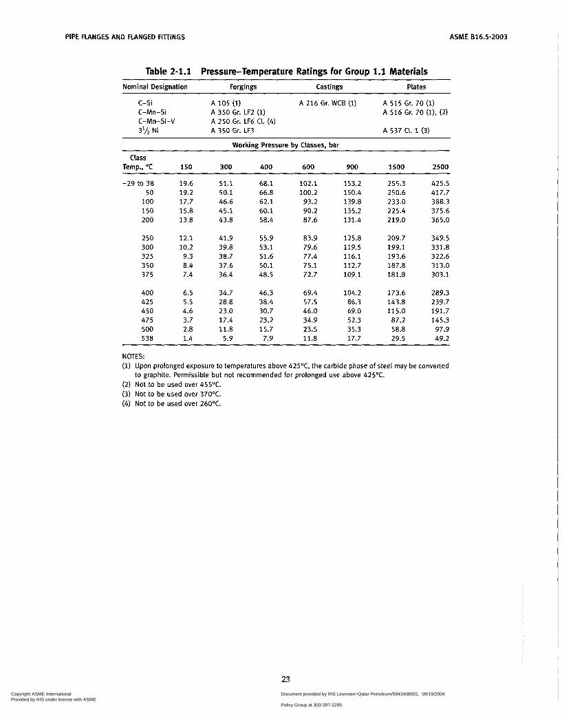
PIPE FLANGES AND FLANGED FIllINGS ASME 616.5-2003
Table 2-1.1 Pressure-Temperature Ratings for Group 1.1 Materials Nominal Designation Forgings Castings Plates
~~~~ ~~~~~~
c-si A 105 (1) A 216 Gr. WCB (1) A 515 Gr. 70 (1) C-Mn-Si C-Mn-Si-V 3'h Ni
A 350 Gr. LF2 (1) A 250 Gr. LF6 CI. (4) A 350 Gr. LF3
A 516 Gr. 70 (l), (2)
A 537 CI. 1 (3)
Working Pressure by Classes. bar
Class Temp., O C 150 300 400 600 900 1500 2500
-29 to 38 50
100 150 200
250 300 325 350 375
400 425 450 475 500 538
19.6 51.1 68.1 19.2 50.1 66.8 17.7 46.6 62.1 15.8 45.1 60.1 13.8 43.8 58.4
12.1 41.9 55.9 10.2 39.8 53.1 9.3 38.7 51.6 8.4 37.6 50.1 7.4 36.4 48.5
6.5 34.7 46.3 5.5 28.8 38.4 4.6 23.0 30.7 3.7 17.4 23.2 2.8 11.8 15.7 1.4 5.9 7.9
102.1 100.2 93.2 90.2 87.6
83.9 79.6 77.4 75.1 72.7
69.4 57.5 46.0 34.9 23.5 11.8
153.2 150.4 139.8 135.2 131.4
125.8 119.5 116.1 112.7 109.1
104.2 86.3 69.0 52.3 35.3 17.7
255.3 250.6 233.0 225.4 219.0
209.7 199.1 193.6 187.8 181.8
173.6 143.8 115.0 87.2 58.8 29.5
425.5 417.7 388.3 375.6 365.0
349.5 331.8 322.6 313.0 303.1
289.3 239.7 191.7 145.3 97.9 49.2
NOTES: (1) Upon prolonged exposure to temperatures above 425OC, the carbide phase of steel may be converted
(2) Not to be used over 455OC. (3) Not to be used over 370OC. (4) Not to be used over 260OC.
to graphite. Permissible but not recommended for prolonged use above 425OC.
23 Copyright ASME International Provided by IHS under license with ASME
Document provided by IHS Licensee=Qatar Petroleum/5943408001, 09/19/200422:36:17 MDT Questions or comments about this message: please call the DocumentPolicy Group at 303-397-2295.
--```,,`,``,,,,`,,``````,,``,`-`-`,,`,,`,`,,`---

ASME 816.5-2003 PIPE FLANGES AND FLANGED FIilINGS
Table 2-1.2 Pressure-Temperature Ratings for Group 1.2 Materials Nominal Designation Forgings Castings Plates
~
C-Mn-Si
C-Mn-Si-V
A 216 Gr. WCC (1) A 352 Gr. LCC (2)
A 350 Gr. LF6 CI. (3)
2'hNi A 352 Gr. LC2 A 302 Gr. B (1)
3%Ni A 352 Gr. LC3 A 203 Gr. E (1)
Working Pressure by Classes, bar
Class Temo.. O C 150 300 400 600 900 1500 2500
-29 to 38 50 100 150
200 250 300 325
3 50 375 400 425
450 475 500 538
19.8 51.7 68.9 19.5 51.7 68.9 17.7 51.5 68.7 15.8 50.2 66.8
13.8 48.6 64.8 12.1 46.3 61.7 10.2 42.9 57.0
9.3 41.4 55.0
8.4 40.0 53.4 7.4 37.8 50.4 6.5 34.7 46.3 5.5 28.8 38.4
4.6 23.0 30.7
2.8 11.6 15.4 1.4 5.9 7.9
3.7 17.1 22.8
103.4 103.4 103.0 100.3
97.2 92.7 85.7 82.6
80.0 75.7 69.4 57.5
46.0 34.2 23.2 11.8
155.1 155.1 154.6 150.5
145.8 139.0
124.0 128.6
120.1 113.5 104.2 86.3
69.0 51.3 34.7 17.7
258.6 258.6 257.6 250.8
243.2
214.4 206.6
231.8
200.1
173.6 189.2
143.8
115.0
57.9 29.5
85.4
430.9 430.9 429.4 418.1
405.4
357.1 344.3
386.2
333.5 315.3
239.7 289.3
191.7 142.4 96.5 49.2
NOTES: (1) Upon prolonged exposure to temperatures above 425OC, the carbide phase of steel may be converted
to graphite. Permissible, but not recommended for prolonged use above 425OC. (2) Not to be used over 340°C. (3) Not to be used over 260OC.
24 Copyright ASME International Provided by IHS under license with ASME
Document provided by IHS Licensee=Qatar Petroleum/5943408001, 09/19/200422:36:17 MDT Questions or comments about this message: please call the DocumentPolicy Group at 303-397-2295.
--```,,`,``,,,,`,,``````,,``,`-`-`,,`,,`,`,,`---
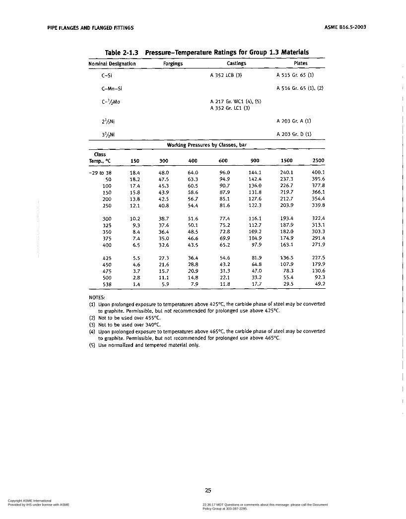
ASME 816.5-2003 PIPE FLANGES AND FLANGED FITnNGS
Table 2-1.3 Pressure-Temperature Ratings for Group 1.3 Materiais Nominal Designation Forgings Castings Plates
c-si A 352 LC8 (3) A 5 1 5 Gr. 65 (1)
C-Mn-Si
C-'hMo
A 516 Gr. 65 (1). (2)
A 217 Gr. WC1 (4). (5) A 352 Gr. L C l (3)
2'hNi
3'/2Ni
A 203 Gr. A (1)
A 203 Gr. D (1) ~~~~ ~ ~
Working Pressures by Classes, bar
Temp., O C 150 300 400 600 900 1500 2500
-29 to 38 18.4 48.0 64.0 96.0 144.1 240.1 400.1 50 18.2 47.5 63.3 94.9 142.4 237.3 395.6
1 O0 17.4 45.3 60.5 90.7 136.0 226.7 377.8 150 15.8 43.9 58.6 87.9 131.8 219.7 366.1 200 13.8 42.5 56.7 85.1 127.6 212.7 354.4 250 12.1 40.8 54.4 81.6 122.3 203.9 339.8
Class
300 10.2 38.7 51.6 77.4 116.1 193.4 322.4 325 9.3 37.6 50.1 75.2 112.7 187.9 313.1 350 8.4 36.4 48.5 72.8 109.2 182.0 303.3 375 7.4 35.0 46.6 69.9 104.9 174.9 291.4 400 6.5 32.6 43.5 65.2 97.9 163.1 271.9
425 5.5 27.3 36.4 54.6 81.9 136.5 227.5 450 4.6 21.6 28.8 43.2 64.8 107.9 179.9 475 3.7 15.7 20.9 31.3 47.0 78.3 130.6 500 2.8 11.1 14.8 22.1 33.2 55.4 92.3 538 1.4 5.9 7.9 11.8 17.7 29.5 49.2
NOTES: (1) Upon prolonged exposure to temperatures above 425OC, the carbide phase of steel may be converted
(2) Not to be used over 455OC. (3) Not to be used over 34O0C. (4) Upon prolonged exposure to temperatures above 465OC, the carbide phase of steel may be converted
(5) Use normalized and tempered material only.
to graphite. Permissible, but not recommended for prolonged use above 425OC.
to graphite. Permissible, but not recommended for prolonged use above 465OC.
25 Copyright ASME International Provided by IHS under license with ASME
Document provided by IHS Licensee=Qatar Petroleum/5943408001, 09/19/200422:36:17 MDT Questions or comments about this message: please call the DocumentPolicy Group at 303-397-2295.
--```,,`,``,,,,`,,``````,,``,`-`-`,,`,,`,`,,`---

ASME 816.5-2003 PIPE FLANGES AND FLANGED FITTINGS
Table 2-1.4 Pressure-Temperature Ratings for Group 1.4 Materials
Nominal Designation Forgings Castings Plates
c-si A 515 Gr. 60 (1)
C-Mn-Si A 350 Gr. LF1, CI. 1 (1) A 516 Gr. 60 (1). (2)
Working Pressures by Classes, bar
Temp., O C 150 300 400 600 900 1500 2500 Class
-29 to 38 50
1 O0 150 200
2 50 300 325 350 375
400 425 450 475 500 538
16.3 42.6 56.7 16.0 41.8 55.7 14.9 38.8 51.8 14.4 37.6 50.1 13.8 36.4 48.5
12.1 34.9 46.6 10.2 33.2 44.2 9.3 32.2 43.0 8.4 31.2 41.7 7.4 30.4 40.5
6.5 29.3 39.1 5.5 25.8 34.4 4.6 21.4 28.5 3.7 14.1 18.8 2.8 10.3 13.7 1.4 5.9 7.9
85.1 83.5 77.7 75.1 72.8
69.8 66.4 64.5 62.5 60.7
58.7 51.5 42.7 28.2 20.6 11.8
127.7 125.3 116.5 112.7 109.2
104.7 99.5 96.7 93.7 91.1
88.0 77.3 64.1 42.3 30.9 17.7
212.8 208.9 194.2 187.8 182.1
174.6 165.9 161.2 156.2 151.8
146.7 128.8 106.8 70.5 51.5 29.5
354.6 348.1 323.6 313.0 303.4
291.0 276.5 268.6 260.4 253.0
244.5 214.7 178.0 117.4 85.9 49.2
NOTES: (1) Upon prolonged exposure to temperatures above 425OC, the carbide phase of steel may be converted
(2) Not to be used over 455°C. to graphite. Permissible, but not recommended for prolonged use above 425OC.
26
Copyright ASME International Provided by IHS under license with ASME
Document provided by IHS Licensee=Qatar Petroleum/5943408001, 09/19/200422:36:17 MDT Questions or comments about this message: please call the DocumentPolicy Group at 303-397-2295.
--```,,`,``,,,,`,,``````,,``,`-`-`,,`,,`,`,,`---
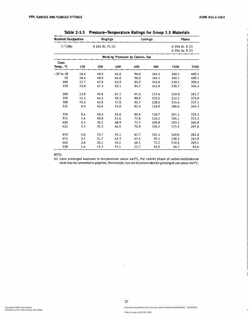
PIPE FLANGES AND FLANGED FIllINGS ASME 616.5-2003
Table 2-1.5 Pressure-Temperature Ratings for Group 1.5 Materials
Nominal Designation Forgings Castings Plates ~ ~~~~~~
C-lLMo A 182 Gr. F1 (1) A 204 Gr. A (1) A 204 Gr. B (1)
Working Pressures by Classes, bar
Temp., OC 150 300 400 600 900 1500 2500
-29 to 38 18.4 48.0 64.0 96.0 144.1 240.1 400.1 50 18.4 48.0 64.0 96.0 144.1 240.1 400.1
100 17.7 47.9 63.9 95.9 143.8 239.7 399.5 150 15.8 47.3 63.1 94.7 142.0 236.7 394.5
Class
200 13.8 45.8 61.1 91.6 137.4 229.0 381.7 250 12.1 44.5 59.3 89.0 133.5 222.5 370.9 300 10.2 42.9 57.0 85.7 128.6 214.4 357.1 325 9.3 41.4 55.0 82.6 124.0 206.6 344.3
350 8.4 40.3 53.6 80.4 120.7 201.1 335.3 375 7.4 38.9 51.6 77.6 116.5 194.1 323.2 400 6.5 36.5 48.9 73.3 109.8 183.1 304.9 42 5 5.5 35.2 46.5 70.0 105.1 175.1 291.6
450 4.6 33.7 45.1 67.7 101.4 169.0 281.8 475 3.7 31.7 42.3 63.4 95.1 158.2 263.9 500 2.8 24.1 32.1 48.1 72.2 120.3 200.5 538 1.4 11.3 15.1 22.7 34.0 56.7 94.6
~ ~~~~~~
NOTE: (1) Upon prolonged exposure to temperatures above 465OC, the carbide phase of carbonmolybdenum
steel may be converted to graphite. Permissible, but not recommended for prolonged use above 465OC.
27 Copyright ASME International Provided by IHS under license with ASME
Document provided by IHS Licensee=Qatar Petroleum/5943408001, 09/19/200422:36:17 MDT Questions or comments about this message: please call the DocumentPolicy Group at 303-397-2295.
--```,,`,``,,,,`,,``````,,``,`-`-`,,`,,`,`,,`---
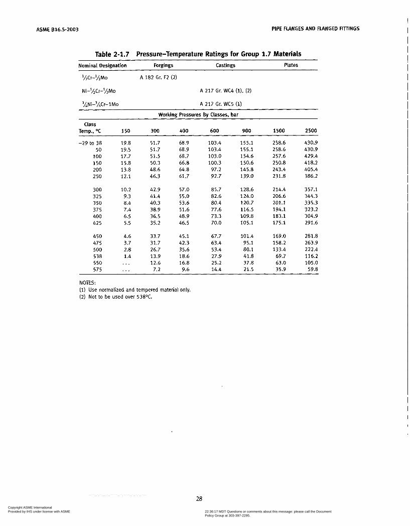
ASME 616.5-2003 PIPE FLANGES AND FLANGED FITTINGS
Table 2-1.7 Pressure-Temperature Ratings for Group 1.7 Materials Nominal Designation Forgings Castings Plates
'/2Cr-'hMo
Ni-'/&r-'/zMo
3hNi-3/,Cr-l Mo
A 182 Gr. F2 (2)
A 217 Gr. WC4 ( i ) , (2)
A 217 Gr. WC5 (1) ~~ ~
Working Pressures By Classes, bar
Temp., O C 150 300 400 600 900 1 soo 2500
-29 to 38 19.8 51.7 68.9 103.4 155.1 258.6 430.9 50 19.5 51.7 68.9 103.4 155.1 258.6 430.9
1 O0 17.7 51.5 68.7 103.0 154.6 257.6 429.4 150 15.8 50.3 66.8 100.3 150.6 250.8 418.2 200 13.8 48.6 64.8 97.2 145.8 243.4 405.4 2 50 12.1 46.3 61.7 92.7 139.0 231.8 386.2
Class
300 10.2 42.9 57.0 85.7 128.6 214.4 357.1 325 9.3 41.4 55.0 82.6 124.0 206.6 344.3 350 8.4 40.3 53.6 80.4 120.7 201.1 335.3 375 7.4 38.9 51.6 77.6 116.5 194.1 323.2 400 6.5 36.5 48.9 73.3 109.8 183.1 304.9 425 5.5 35.2 46.5 70.0 105.1 175.1 291.6
450 4.6 33.7 45.1 67.7 101.4 169.0 281.8 475 3.7 31.7 42.3 63.4 95.1 158.2 263.9 500 2.8 26.7 35.6 53.4 80.1 133.4 222.4 538 1.4 13.9 18.6 27.9 41.8 69.7 116.2 5 50 ... 12.6 16.8 25.2 37.8 63.0 105.0 575 ... 7.2 9.6 14.4 21.5 35.9 59.8
NOTES: (1) Use normalized and tempered material only. (2) Not to be used over 538°C.
28 Copyright ASME International Provided by IHS under license with ASME
Document provided by IHS Licensee=Qatar Petroleum/5943408001, 09/19/200422:36:17 MDT Questions or comments about this message: please call the DocumentPolicy Group at 303-397-2295.
--```,,`,``,,,,`,,``````,,``,`-`-`,,`,,`,`,,`---

ASME 816.5-2003 PIPE FLANGES AND FLANGED FITTINGS
Table 2-1.9 Pressure-Temperature Ratings for Group 1.9 Materials ~
Nominal Designation Forgings Castings Plates
l%Cr-%Mo
11hCr-1/2Mo-Si
A 217 Gr. WC6 (l), (3)
A 182 Gr. F 1 1 CI. 2 (i), (2) A 387 Gr. 11 Ci. 2 (2)
Working Pressures by Classes, bar
Temp., O C 150 300 400 600 900 1500 2500 Class
-29 to 38 50
1 O0 150 200 250
300 325 350 375 400 425
450 475 500 538 5 50 575 600 625 650
19.8 19.5 17.7 15.8 13.8 12.1
10.2 9.3 8.4 7.4 6.5 5.5
4.6 3.7 2.8 1.4 ... . . . . . . ... . . .
51.7 51.7 51.5 49.7 48.0 46.3
42.9 41.4 40.3 38.9 36.5 35.2
33.7 31.7 25.7 14.9 12.7 8.8 6.1 4.3 2.8
68.9 68.9 68.6 66.3 63.9 61.7
57.0 55.0 53.6 51.6 48.9 46.5
45.1 42.3 34.3 19.9 16.9 11.7
8.1 5.7 3.8
103.4 103.4 103.0 99.5 95.9 92.7
85.7 82.6 80.4 77.6 73.3 70.0
67.7 63.4 51.5 29.8 25.4 17.6 12.2 8.5 5.7
155.1 155.1 154.4 149.2 143.9 139.0
128.6 124.0 120.7 116.5 109.8 105.1
1 01.4 95.1 77.2 44.7 38.1 26.4 18.3 12.8 8.5
258.6 258.6 257.4 248.7 239.8 231.8
214.4 206.6 201.1 194.1 183.1 175.1
169.0 158.2 128.6
74.5 63.5 44.0 30.5 21.3 14.2
430.9 430.9 429.0 414.5 399.6 386.2
357.1 344.3 335.3 323.2 304.9 291.6
281.8 263.9 214.4 124.1 105.9
73.4 50.9 35.5 23.6
NOTES: (1) Use normalized and tempered material only. (2) Permissible, but not recommended for prolonged use above 590OC. (3) Not to be used over 590OC.
29
Copyright ASME International Provided by IHS under license with ASME
Document provided by IHS Licensee=Qatar Petroleum/5943408001, 09/19/200422:36:17 MDT Questions or comments about this message: please call the DocumentPolicy Group at 303-397-2295.
--```,,`,``,,,,`,,``````,,``,`-`-`,,`,,`,`,,`---

ASME 816.5-2003 PIPE FLANGES AND FLANGED FIllINGS
Table 2-1.10 Pressure-Temperature Ratings for Group 1.10 Materiais
Nominal Designation Forgings Castings Plates
2'LCr-lMo A 182 Gr. F22 CI. 3 (2) A 217 Gr. WC9 (i), (3) A 387 Gr. 22 CI. 2 (2)
Working Pressures bv Classes. bar
Class Temp., O C 150 300 400 600 900 1500 2500
-29 t O 38 50
100 150 200
250 300 325 3 50 375
400 425 450 475 500
538 550 575 600 625 650
19.8 51.7 68.9 19.5 51.7 68.9 17.7 51.5 68.7 15.8 50.3 66.8 13.8 48.6 64.8
12.1 46.3 61.7 10.2 42.9 57.0 9.3 41.4 55.0 8.4 40.3 53.6 7.4 38.9 51.6
6.5 36.5 48.9 5.5 35.2 46.5 4.6 33.7 45.1 3.7 31.7 42.3 2.8 28.2 37.6
1.4 18.4 24.6 . . . 15.6 20.8 . . . 10.5 14.0 ... 6.9 9.2 . . . 4.5 6.0 . . . 2.8 3.8
103.4 103.4 103.0 100.3
97.2
92.7 85.7 82.6 80.4 77.6
73.3 70.0 67.7 63.4 56.5
36.9 31.3 21.1 13.8 8.9 5.7
155.1 155.1 154.6 150.6 145.8
139.0 128.6 124.0 120.7 116.5
109.8 105.1 101.4 95.1 84.7
55.3 46.9 31.6 20.7 13.4 8.5
258.6 258.6 257.6 250.8 243.4
231.8 214.4 206.6 201.1 194.1
183.1 175.1 169.0 158.2 140.9
92.2 78.2 52.6 34.4 22.3 14.2
430.9 430.9 429.4 418.2 405.4
386.2 357.1 344.3 335.3 323.2
304.9 291.6 281.8 263.9 235.0
153.7 130.3 87.7 57.4 37.2 23.6
NOTES: (1) Use normalized and tempered material only. (2) Permissible, but not recommended for prolonged use above 590OC. (3) Not to be used over 590OC.
30 Copyright ASME International Provided by IHS under license with ASME
Document provided by IHS Licensee=Qatar Petroleum/5943408001, 09/19/200422:36:17 MDT Questions or comments about this message: please call the DocumentPolicy Group at 303-397-2295.
--```,,`,``,,,,`,,``````,,``,`-`-`,,`,,`,`,,`---
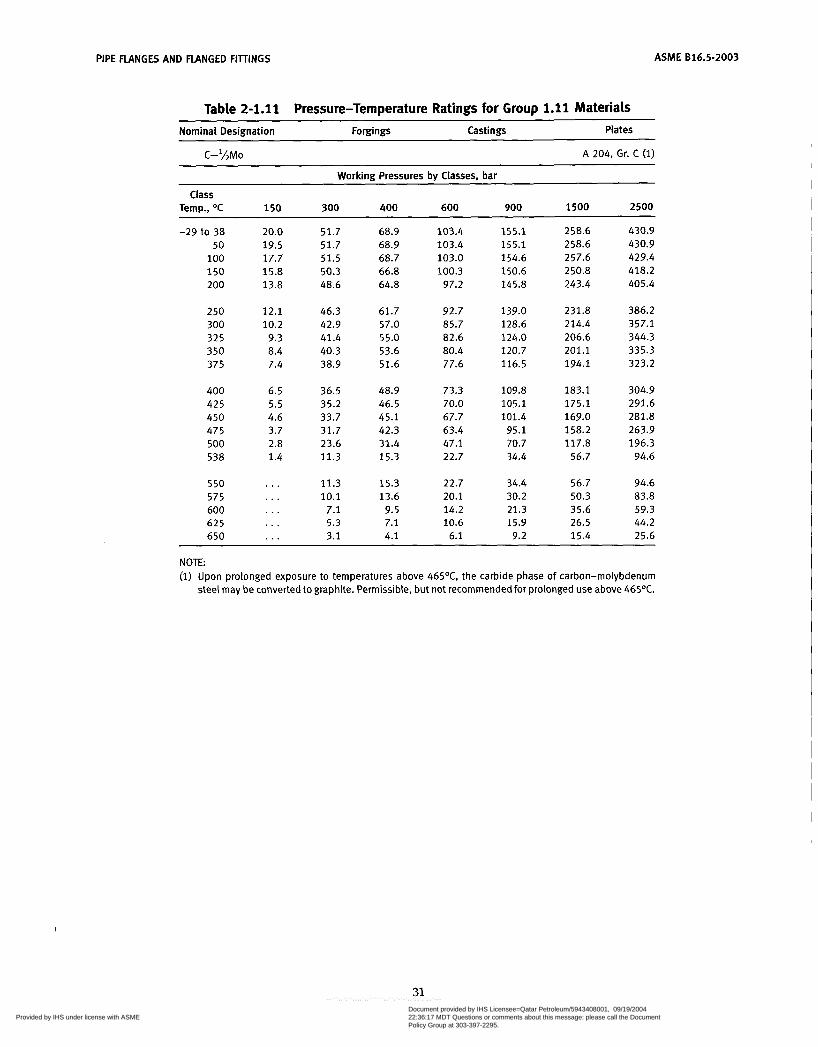
PIPE FLANGES AND FLANGED FIllINGS ASME 616.5-2003
Table 2-1.11 Pressure-Temperature Ratings for Group 1.1 1 Materiais Nominal Designation Forgings Castings Plates
C-'AMo A 204, Gr. C (1)
Working Pressures by Classes, bar
Temp., O C 150 300 400 600 900 1500 2500 Class
-29 to 38 50
100 150 200
250 300 325 350 375
400 425 450 475 500 538
550 575 600 625 650
20.0 19.5 17.7 15.8 13.8
12.1 10.2
9.3 8.4 7.4
6.5 5.5 4.6 3.7 2.8 1.4
...
. . .
. . .
. . .
. . .
51.7 68.9 51.7 68.9 51.5 68.7 50.3 66.8 48.6 64.8
46.3 61.7 42.9 57.0 41.4 55.0 40.3 53.6 38.9 51.6
36.5 48.9 35.2 46.5 33.7 45.1 31.7 42.3 23.6 31.4 11.3 15.3
11.3 15.3 10.1 13.6
7.1 9.5 5.3 7.1 3.1 4.1
103.4 103.4 103.0 100.3
97.2
92.7 85.7
80.4 77.6
73.3 70.0 67.7 63.4 47.1 22.7
22.7 20.1 14.2 10.6
6.1
82.6
155.1 155.1 154.6 150.6 145.8
139.0 128.6 124.0 120.7 116.5
109.8 105.1 101.4
95.1 70.7 34.4
34.4 30.2 21.3 15.9 9.2
258.6 258.6 257.6 250.8 243.4
231.8 214.4 206.6 201.1 194.1
183.1 175.1 169.0 158.2 117.8
56.7
56.7 50.3 35.6 26.5 15.4
430.9 430.9 429.4 418.2 405.4
386.2 357.1 344.3 335.3 323.2
304.9 291.6 281.8 263.9 196.3
94.6
94.6 83.8 59.3 44.2 25.6
NOTE: (1) Upon prolonged exposure to temperatures above 465% the carbide phase of carbon-molybdenum
steel may be converted to graphite. Permissible, but not recommended for prolonged use above 465OC.
31 Copyright ASME International Provided by IHS under license with ASME
Document provided by IHS Licensee=Qatar Petroleum/5943408001, 09/19/200422:36:17 MDT Questions or comments about this message: please call the DocumentPolicy Group at 303-397-2295.
--```,,`,``,,,,`,,``````,,``,`-`-`,,`,,`,`,,`---
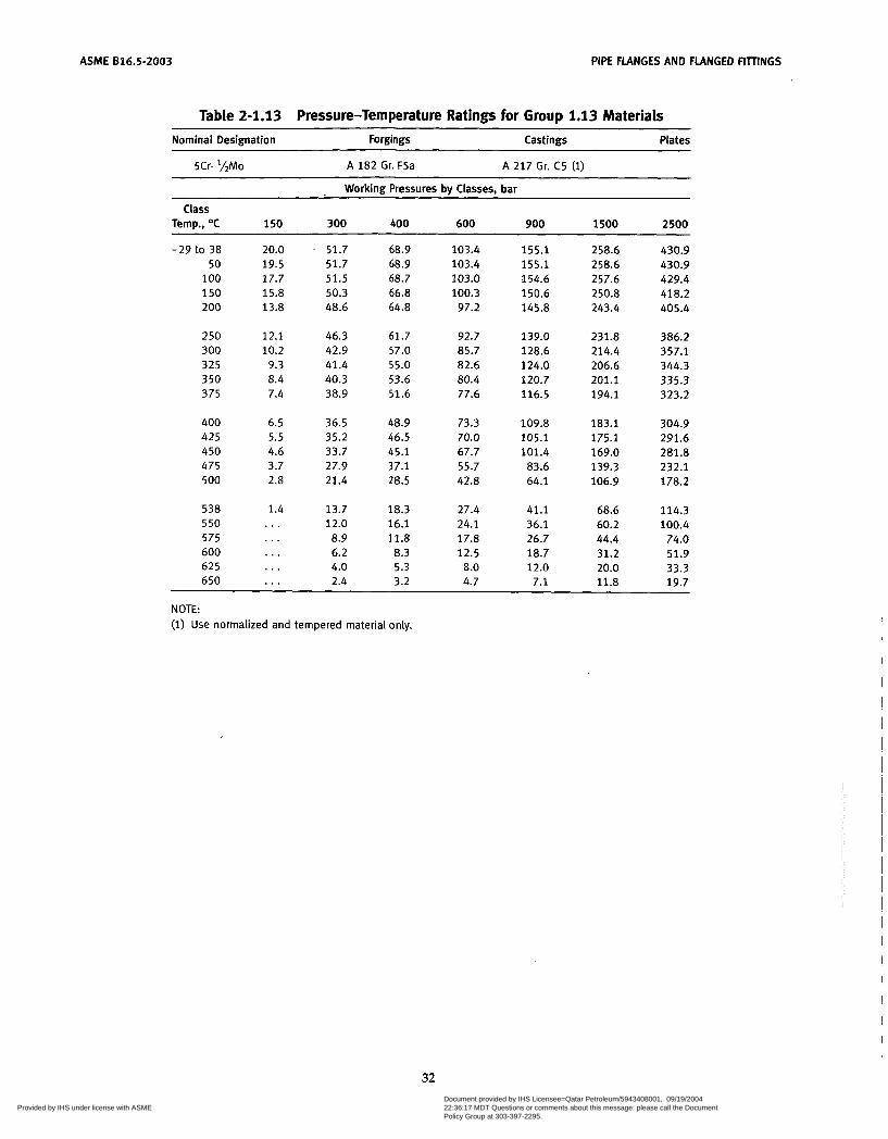
ASME 616.5-2003 PIPE FLANGES AND FLANGED FITTINGS
Table 2-1.13 Pressure-Temperature Ratings for Group 1.13 Materials Nominal Designation Forgings Castings Plates
5Cr-'/*Mo A 182 Gr. F5a A 217 Gr. C5 (1)
Working Pressures bv Classes, bar
Class Temp., O C 150 300 400 600 900 1500 2500
-29 to 38 20.0 . 51.7 68.9 103.4 155.1 258.6 430.9 50 19.5 51.7 68.9 103.4 155.1 258.6 430.9
1 O0 17.7 51.5 68.7 103.0 154.6 257.6 429.4 150 15.8 50.3 66.8 100.3 150.6 250.8 418.2 200 13.8 48.6 64.8 97.2 145.8 243.4 405.4
250 12.1 46.3 61.7 92.7 139.0 231.8 386.2 300 10.2 42.9 57.0 85.7 128.6 214.4 357.1 325 9.3 41.4 55.0 82.6 124.0 206.6 344.3 350 8.4 40.3 53.6 80.4 120.7 201.1 335.3 375 7.4 38.9 51.6 77.6 116.5 194.1 323.2
400 6.5 36.5 48.9 73.3 109.8 183.1 304.9 425 5.5 35.2 46.5 70.0 105.1 175.1 291.6 450 4.6 33.7 45.1 67.7 101.4 169.0 281.8 475 3.7 27.9 37.1 55.7 83.6 139.3 232.1 500 2.8 21.4 28.5 42.8 64.1 106.9 178.2
538 1.4 13.7 18.3 27.4 41.1 68.6 114.3 5 50 ... 12.0 16.1 24.1 36.1 60.2 100.4 575 ... 8.9 11.8 17.8 26.7 44.4 74.0 600 ... 6.2 8.3 12.5 18.7 31.2 51.9 625 . . . 4.0 5.3 8.0 12.0 20.0 33.3 650 ... 2.4 3.2 4.7 7.1 11.8 19.7
NOTE: (1) Use normalized and tempered material only.
32 Copyright ASME International Provided by IHS under license with ASME
Document provided by IHS Licensee=Qatar Petroleum/5943408001, 09/19/200422:36:17 MDT Questions or comments about this message: please call the DocumentPolicy Group at 303-397-2295.
--```,,`,``,,,,`,,``````,,``,`-`-`,,`,,`,`,,`---

ASME 016.5-2003 PIPE FLANGES AND FLANGED FIlTINGS
Table 2-1.14 Pressure-Temperature Ratings for Group 1.14 Materials Nominal Designation Forgings Castings Plates
9Cr-1Mo A 182 Gr. F9 A 217 Gr. C12 (1)
Working Pressures by Ciasses, bar
Class Temp., O C 150 300 400 600 900 1500 2500
-29 to 38 50
100 150 200
250 300 325 350 375
400 425 450 475 500
538 550 575 600 625 650
20.0 51.7 68.9 19.5 51.7 68.9 17.7 51.5 68.7 15.8 50.3 66.8 13.8 48.6 64.8
12.1 46.3 61.7 10.2 42.9 57.0
9.3 41.4 55.0 8.4 40.3 53.6 7.4 38.9 51.6
6.5 36.5 48.9 5.5 35.2 46.5 4.6 33.7 45.1 3.7 31.7 42.3 2.8 28.2 37.6
1.4 17.5 23.3 ... 15.0 20.0 . . . 10.5 13.9 ... 7.2 9.6 . . . 5.0 6.6 ... 3.5 4.7
103.4 103.4 103.0 100.3
97.2
92.7 85.7 82.6 80.4 77.6
73.3 70.0 67.7 63.4 56.5
35.0 30.0 20.9 14.4
9.9 7.1
155.1 155.1 154.6 150.6 145.8
139.0 128.6 124.0 120.7 116.5
109.8 105.1 101.4
95.1 84.7
52.5 45.0 31.4 21.5 14.9 10.6
258.6 258.6 257.6 250.8 243.4
231.8 214.4 206.6 201.1 194.1
183.1 175.1 169.0 158.2 140.9
87.5 75.0 52.3 35.9 24.8 17.7
430.9 430.9 429.4 418.2 405.4
386.2 357.1 344.3 335.3 323.2
304.9 291.6 281.8 263.9 235.0
145.8 125.0
87.1 59.8 41.4 29.5
NOTE: (1) Use normalized and tempered material only.
33 Copyright ASME International Provided by IHS under license with ASME
Document provided by IHS Licensee=Qatar Petroleum/5943408001, 09/19/200422:36:17 MDT Questions or comments about this message: please call the DocumentPolicy Group at 303-397-2295.
--```,,`,``,,,,`,,``````,,``,`-`-`,,`,,`,`,,`---
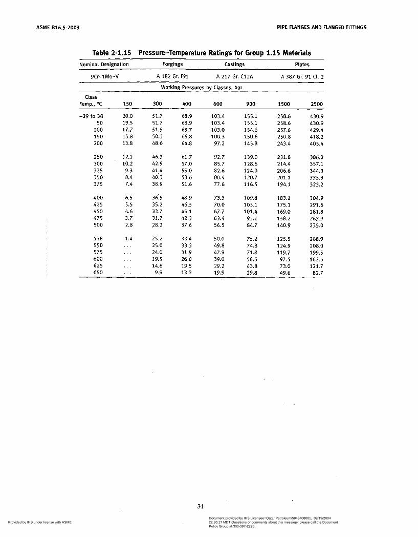
ASME 816.5-2003 PIPE FLANGES AND FLANGED FIllINGS
Table 2-1.15 Pressure-Temperature Ratings for Group 1.15 Materiais
Nominal Designation Forgings Castings Plates
9Cr-1Mo-V A 182 Gr. F91 A 217 Gr. C12A A 387 Gr. 91 CI. 2
Working Pressures by Classes, bar
Class Temp., OC 150 300 400 600 900 1500 2500
-29 to 38 20.0 51.7 68.9 103.4 155.1 258.6 430.9 50 19.5 51.7 68.9 103.4 155.1 258.6 430.9 100 17.7 51.5 68.7 103.0 154.6 257.6 429.4 150 15.8 50.3 66.8 100.3 150.6 250.8 418.2 200 13.8 48.6 64.8 97.2 145.8 243.4 405.4
250 12.1 46.3 61.7 92.7 139.0 231.8 386.2 300 10.2 42.9 57.0 85.7 128.6 214.4 357.1 325 9.3 41,4 55.0 82.6 124.0 206.6 344.3 350 8.4 40.3 53.6 80.4 120.7 201.1 335.3 375 7.4 38.9 51.6 77.6 116.5 194.1 323.2
400 6.5 36:5 48.9 73.3 109.8 183.1 304.9 425 5.5 35.2 46.5 70.0 105.1 175.1 291.6 450 4.6 33.7 45.1 67.7 101.4 169.0 281.8 475 3.7 31.7 42.3 63.4 95.1 158.2 263.9 500 2.8 28.2 37.6 56.5 84.7 140.9 235.0
538 1.4 25.2 33.4 50.0 75.2 125.5 208.9 550 ... 25.0 33.3 49.8 74.8 124.9 208.0 575 ... 24.0 31.9 47.9 71.8 119.7 199.5 600 . . . 19.5 26.0 39.0 58.5 97.5 162.5 625 ... 14.6 19.5 29.2 43.8 73.0 121.7 650 . . . 9.9 13.2 19.9 29.8 49.6 82.7
34
Copyright ASME International Provided by IHS under license with ASME
Document provided by IHS Licensee=Qatar Petroleum/5943408001, 09/19/200422:36:17 MDT Questions or comments about this message: please call the DocumentPolicy Group at 303-397-2295.
--```,,`,``,,,,`,,``````,,``,`-`-`,,`,,`,`,,`---
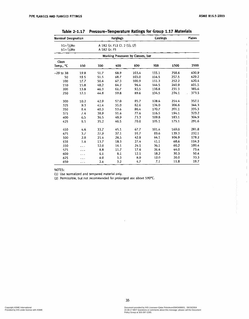
PIPE FLANGES AND FLANGED FITTINGS ASME 816.5-2003
Table 2-1.17 Pressure-Temperature Ratings for Group 1.17 Materials Nominal Designation Forgings Castings Plates
lCr-'LMo 5Cr-*/,Mo A 182 Gr. F5
A 182 Gr. F12 CI. 2 (1). (2)
Workinn Pressures by Classes, bar
Class Temp., O C 150 300 400 600 900 1500 2500
-29 to 38 50
100 150 200 250
300 325 350 375 400 425
450 475 500 538 550 575 600 625 650
19.8 51.7 19.5 51.5 17.7 50.4 15.8 48.2 13.8 46.3 12.1 44.8
10.2 42.9 9.3 41.4 8.4 40.3 7.4 38.9 6.5 36.5 5.5 35.2
4.6 33.7 3.7 27.9 2.8 21.4 1.4 13.7 . . . 12.0 . . . 8.8 . . . 6.1 . . . 4.0 . . . 2.4
68.9 68.7 67.3 64.2 61.7 59.8
57.0 55.0 53.6 51.6 48.9 46.5
45.1 37.1 28.5 18.3 16.1 11.7 8.1 5.3 3.2
103.4 103.0 100.9 96.4 92.5 89.6
85.7 82.6 80.4 77.6 73.3 70.0
67.7 55.7 42.8 27.4 24.1 17.6 12.1
8.0 4.7
155.1 154.5 151.3 144.5 138.8 134.5
128.6 124.0 120.7 116.5 109.8 105.1
101.4 83.6 64.1 41.1 36.1 26.4 18.2 12.0 7.1
258.6 257.5 252.2 240.9 231.3 224.1
214.4 206.6 201.1 194.1 183.1 175.1
169.0 139.3 106.9 68.6 60.2 44.0 30.3 20.0 11.8
430.9 429.2 420.4 401.5 385.6 373.5
357.1 344.3 335.3 323.2 304.9 291.6
281.8 232.1 178.2 114.3 100.4
73.4 50.4 33.3 19.7
NOTES: (1) Use normalized and tempered material only. (2) Permissible, but not recommended for prolonged use above 590OC.
35
Copyright ASME International Provided by IHS under license with ASME
Document provided by IHS Licensee=Qatar Petroleum/5943408001, 09/19/200422:36:17 MDT Questions or comments about this message: please call the DocumentPolicy Group at 303-397-2295.
--```,,`,``,,,,`,,``````,,``,`-`-`,,`,,`,`,,`---
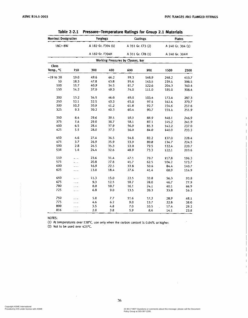
ASME B16.5-2003 PIPE FLANGES AND FLANGED FIllINGS
Table 2-2.1 Pressure-Temperature Ratings for Group 2.1 Materials
Nominal Designation Forgings Castings Plates
18Cr-8Ni A 182 Gr. F304 (1) A 3 5 1 Gr. CF3 (2) A 240 Gr. 304 (1)
A 182 Gr. F304H A 351 Gr. CF8 (1) A 240 Gr. 304H
Working Pressures by Classes, bar
Temp., OC 150 300 400 600 900 1500 2500 Class
-29 to 38 50
100 150
200 2 50 300 325
350 375 400 425
450 475 500 538
550 575 600 625
650 675 700 725
750 775 800 816
19.0 18.3 15.7 14.2
13.2 12.1 10.2 9.3
8.4 7.4 6.5 5.5
4.6 3.7 2.8 1.4
. . .
...
. . .
. . .
. . .
...
. . .
. . .
. . .
...
. . .
. . .
49.6 47.8 40.9 37.0
34.5 32.5 30.9 30.2
29.6 29.0 28.4 28.0
27.4 26.9 26.5 24.4
23.6 20.8 16.9 13.8
11.3 9.3 8.0 6.8
5.8 4.6 3.5 2.8
66.2 63.8 54.5 49.3
46.0 43.3 41.2 40.3
39.5 38.7 37.9 37.3
36.5 35.9 35.3 32.6
31.4 27.8 22.5 18.4
15.0 12.5 10.7
9.0
7.7 6.2 4.8 3.8
99.3 95.6 81.7 74.0
69.0 65.0 61.8 60.4
59.3 58.1 56.9 56.0
54.8 53.9 53.0 48.9
47.1 41.7 33.8 27.6
22.5 18.7 16.1 13.5
11.6 9.0 7.0 5.9
148.9 143.5 122.6 111.0
103.4 97.5 92.7 90.7
88.9 87.1 85.3 84.0
82.2 80.8 79.5 73.3
70.7 62.5 50.6 41.4
33.8 28.0 24.1 20.3
17.3 13.7 10.5 8.6
248.2 239.1 204.3 185.0
172.4 162.4 154.6 151.1
148.1 145.2 142.2 140.0
137.0 134.7 132.4 122.1
117.8 104.2
84.4 68.9
56.3 46.7 40.1 33.8
28.9 22.8 17.4 14.1
413.7 398.5 340.4 308.4
287.3 270.7 257.6 251.9
246.9 241.9 237.0 233.3
228.4 224.5 220.7 203.6
196.3 173.7 140.7 114.9
93.8 77.9 66.9 56.3
48.1 38.0 29.2 23.8
NOTES: (1) At temperatures over 538OC, use only when the carbon content is 0.04% or higher. (2) Not to be used over 425OC.
36 Copyright ASME International Provided by IHS under license with ASME
Document provided by IHS Licensee=Qatar Petroleum/5943408001, 09/19/200422:36:17 MDT Questions or comments about this message: please call the DocumentPolicy Group at 303-397-2295.
--```,,`,``,,,,`,,``````,,``,`-`-`,,`,,`,`,,`---
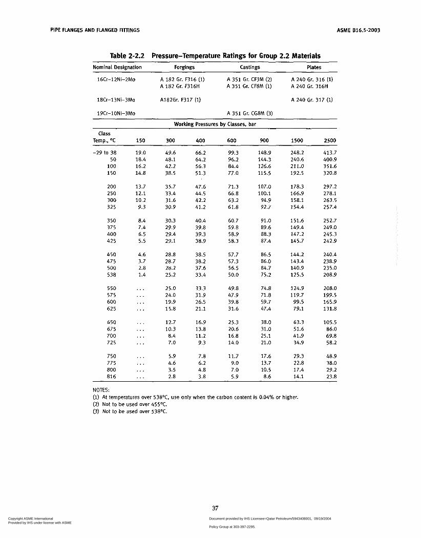
ASME 816.5-2003 PIPE FLANGES AND FLANGED FIllINGS
Table 2-2.2 Pressure-Temperature Ratings for Group 2.2 Materiais ~ ~
Nominal Designation Forgings Castings ~
Plates
16Cr-12Ni-ZMo A 182 Gr. F316 (1) A 182 Gr. F316H
A 351 Gr. CF3M (2) A 351 Gr. CF8M (i)
A 240 Gr. 316 (1) A 240 Gr. 316H
18Cr-13Ni-3Mo A182Gr. F317 (1) A 240 Gr. 317 (1)
19Cr-1ONi-3Mo A 351 Gr. CG8M (3)
Workinn Pressures bv Classes. bar
Class Temp., O C 150 300 400 600 900 1500 2500
-29 to 38 50
100 150
200 250 300 325
350 375 400 425
450 475 500 538
550 575 600 625
650 675 700 725
750 775 800 816
19.0 18.4 16.2 14.8
13.7 12.1 10.2 9.3
8.4 7.4 6.5 5.5
4.6 3.7
1.4 2.8
. . .
. . .
...
. . .
. . .
...
...
. . .
...
...
...
. . .
49.6 48.1 42.2 38.5
35.7 33.4 31.6 30.9
30.3 29.9 29.4 29.1
28.8 28.7
25.2
25.0 24.0 19.9 15.8
12.7 10.3 8.4 7.0
5.9 4.6 3.5 2.8
28.2
66.2 64.2 56.3 51.3
47.6 44.5 42.2 41.2
40.4 39.8 39.3 38.9
38.5 38.2 37.6 33.4
33.3 31.9 26.5 21.1
16.9 13.8 11.2 9.3
7.8 6.2 4.8 3.8
99.3 96.2 84.4 77.0
71.3 66.8 63.2 61.8
60.7 59.8 58.9 58.3
57.7 57.3 56.5 50.0
49.8 47.9 39.8 31.6
25.3 20.6 16.8 14.0
11.7 9.0 7.0 5.9
148.9 144.3 126.6 115.5
107.0 100.1
94.9 92.7
91.0 89.6 88.3 87.4
86.5
84.7 75.2
74.8 71.8 59.7 47.4
38.0 31.0 25.1 21.0
17.6 13.7 10.5 8.6
86.0
248.2 240.6 211.0 192.5
178.3 166.9 158.1 154.4
151.6 149.4 147.2 145.7
144.2 143.4 140.9 125.5
124.9 119.7
99.5 79.1
63.3 51.6 41.9 34.9
29.3 22.8 17.4 14.1
413.7 400.9 351.6 320.8
297.2 278.1 263.5 257.4
252.7 249.0 245.3 242.9
240.4 238.9 235.0 208.9
208.0 199.5 165.9 131.8
105.5 86.0 69.8 58.2
48.9 38.0 29.2 23.8
NOTES: (1) At temperatures over 538OC, use only when the carbon content is 0.04% or higher. (2) Not to be used over 455OC. (3) Not to be used over 538OC.
37 Copyright ASME International Provided by IHS under license with ASME
Document provided by IHS Licensee=Qatar Petroleum/5943408001, 09/19/200422:36:17 MDT Questions or comments about this message: please call the DocumentPolicy Group at 303-397-2295.
--```,,`,``,,,,`,,``````,,``,`-`-`,,`,,`,`,,`---

ASME 816.5-2003 PIPE FLANGES AND FLANGED FITTINGS
Table 2-2.3 Pressure-Temperature Ratings for Group 2.3 Materials
Nominal Designation Forgings Castings Plates
16Cr-12Ni-2Mo A 182 Gr. F316L 18Cr-8Ni A 182 Gr. F304L (1)
A 240 Gr. 316L A 240 Gr. 304L ( i )
Working Pressures bv Classes, bar
Class Temp., OC 150 300 400 600 900 1500 2500
-29 to 38 15.9 41.4 55.2 50 15.3 40.0 53.4
100 13.3 34.8 46.4 150 12.0 31.4 41.9
200 11.2 29.2 38.9 250 10.5 27.5 36.6 300 10.0 26.1 34.8 325 9.3 25.5 34.0
350 8.4 25.1 33.4 375 7.4 24.8 33.0 400 6.5 24.3 32.4 425 5.5 23.9 31.8 450 4.6 23.4 31.2
82.7 80.0 69.6 62.8
58.3 54.9 52.1 51.0
50.1 49.5 48.6 47.7 46.8
124.1 120.1 104.4
94.2
87.5 82.4 78.2 76.4
75.2 74.3 72.9 71.6 70.2
206.8 344.7 200.1 333.5 173.9 289.9 157.0 261.6
145.8 243.0 137.3 228.9 130.3 217.2 127.4 212.3
125.4 208.9 123.8 206.3 121.5 202.5 119.3 198.8 117.1 195.1
NOTE: (1) Not to be used over 425OC.
38 Copyright ASME International Provided by IHS under license with ASME
Document provided by IHS Licensee=Qatar Petroleum/5943408001, 09/19/200422:36:17 MDT Questions or comments about this message: please call the DocumentPolicy Group at 303-397-2295.
--```,,`,``,,,,`,,``````,,``,`-`-`,,`,,`,`,,`---
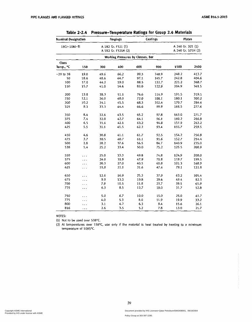
PIPE FLANGES AND FLANGED FIlTINGS ASME 816.5-2003
Table 2-2.4 Pressure-Temperature Ratings for Group 2.4 Materiais Nominal Designation Forgings Castings Plates
18Cr-1ONi-Ti A 182 Gr. F321 (1) A 182 Gr. F321H (2)
A 240 Gr. 321 (i) A 240 Gr. 321H (2)
Workina Pressures bv Classes. bar
Class Temp., O C 150 300 400 600 900 1500 2500
-29 to 38 50
1 O0 150
200 250 300 325
350 375 400 425
450 475 500 538
550 575 600 625
650 675 700 725
750 775 800 816
19.0 18.6 17.0 15.7
13.8 12.1 10.2 9.3
8.4 7.4 6.5 5.5
4.6 3.7 2.8 1.4
. . .
. . .
. . .
. . .
...
. . .
. . .
...
. . .
. . .
...
. . .
49.6 48.6 44.2 41.0
38.3 36.0 34.1 33.3
32.6 32.0 31.6 31.1
30.8 30.5 28.2 25.2
25.0 24.0 20.3 15.8
12.6 9.9 7.9 6.3
5.0 4.0 3.1 2.6
66.2 64.7 59.0 54.6
51.1 48.0 45.5 44.4
43.5 42.7 42.1 41.5
41.1 40.7 37.6 33.4
33.3 31.9 27.0 21.1
16.9 13.2 10.5
8.5
6.7 5.3 4.2 3.5
99.3 97.1 88.5 82.0
76.6 72.0 68.3 66.6
65.2 64.1 63.2 62.3
61.7 61.1 56.5 50.0
49.8 47.9 40.5 31.6
25.3 19.8 15.8 12.7
10.0 8.0 6.3 5.2
148.9 145.7 132.7 122.9
114.9 108.1 102.4 99.9
97.8 96.1 94.8 93.4
92.5 91.6 84.7 75.2
74.8 71.8 60.8 47.4
37.9 29.6 23.7 19.0
15.0 11.9 9.4 7.8
248.2 242.8 221.2 204.9
191.5 180.1 170.7 166.5
163.0 160.2 157.9 155.7
154.2 152.7 140.9 125.5
124.9 119.7 101.3
79.1
63.2 49.4 39.5 31.7
25.0 19.9 15.6 13.0
413.7 404.6 368.7 341.5
319.1 300.2 284.6 277.6
271.7 266.9 263.2 259.5
256.9 254.4 235.0 208.9
208.0 199.5 168.9 131.8
105.4 82.3 65.9 52.8
41.7 33.2 26.1 21.7
NOTES: (1) Not to be used over 538OC. (2) At temperatures over 538OC, use only if the material is heat treated by heating to a minimum
temperature of 1095OC.
39
Copyright ASME International Provided by IHS under license with ASME
Document provided by IHS Licensee=Qatar Petroleum/5943408001, 09/19/200422:36:17 MDT Questions or comments about this message: please call the DocumentPolicy Group at 303-397-2295.
--```,,`,``,,,,`,,``````,,``,`-`-`,,`,,`,`,,`---

ASME 816.5-2003 PIPE FLANGES AND FLANGED FITINGS
Table 2-2.5 Pressure-Temperature Ratings for Group 2.5 Materials ~~ ~ ~ ~~
Nominal Designation Forgings Castings Plates
18Cr-1ONi-Cb A 182 Gr. F347 (i) A 182 Gr. F347H (2) A 182 Gr. F348 (i) A 182 Gr. F348H (2)
A 240 Gr. 347 (i) A 240 Gr. 347H (2) A 240 Gr. 348 (1) A 240 Gr. 348H (2)
Working Pressures by Classes, bar Class
Temp., OC 150 300 400 600 900 1500 2500
-29 to 38 50
100 150
200 250 300 325
350 375 400 42 5
450 475 500 538
5 50 575 600 625
650 675 700 72 5 750 775 800 816
19.0 18.7 17.4 15.8
13.8 12.1 10.2
9.3
8.4 7.4 6.5 5.5
4.6 3.7 2.8 1.4
. . .
. . .
...
. . .
. . .
. . .
. . .
...
. . .
. . .
. . .
. . .
49.6 48.8 45.3 42.5
39.9 37.8 36.1 35.4
34.8 34.2 33.9 33.6
33.5 31.7 28.2 25.2
25.0 24.0 21.6 18.3
14.1 12.4 10.1
7.9 5.9 4.6 3.5 2.8
66.2 65.0 60.4 56.6
53.3 50.4 48.1 47.1
46.3 45.6 45.2 44.8
44.6 42.3 37.6 33.4
33.3 31.9 28.6 24.3
18.9 16.9 13.4 10.5 7.9 6.2 4.8 3.8
99.3 97.5 90.6 84.9
79.9 75.6 72.2 70.7
69.5 68.4 67.8 67.2
66.9 63.4 56.5 50.0
49.8 47.9 42.9 36.6
28.1 25.2 20.0 15.4 11.7 9.0 7.0 5.9
148.9 146.3 135.9 127.4
119.8 113.4 108.3 106.1
104.3 102.6 101.7 100.8
100.4 95.1 84.7 75.2
74.8 71.8 64.2 54.9
42.5 37.6 29.8 23.2 17.6 13.7 10.5 8.6
248.2 243.8 226.5 212.4
199.7 189.1 180.4 176.8
173.8 171.0 169.5 168.1
167.3 158.2 140.9 125.5
124.9 119.7 107.0 91.2
70.7 62.7 49.7 38.6 29.6 22.8 17.4 14.1
413.7 406.4 377.4 353.9
332.8 315.1 300.7 294.6
289.6 285.1 282.6 280.1
278.8 263.9 235.0 208.9
208.0 199.5 178.5 152.0
117.7 104.5
83.0 64.4 49.1 38.0 29.2 23.8
NOTES: (1) Not to be used over 538'C. (2) for temperatures over 538OC, use only i f the material is heat treated by heating to a minimum
temperature of 1095'C.
40
. Copyright ASME International Provided by IHS under license with ASME
Document provided by IHS Licensee=Qatar Petroleum/5943408001, 09/19/200422:36:17 MDT Questions or comments about this message: please call the DocumentPolicy Group at 303-397-2295.
--```,,`,``,,,,`,,``````,,``,`-`-`,,`,,`,`,,`---
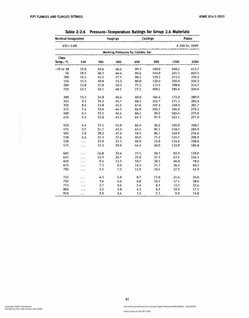
PIPE FLANGES AND FLANGED FITTINGS ASME 816.5-2003
Table 2-2.6 Pressure-Temperature Ratings for Group 2.6 Materiais Nominal Designation Forgings Castings Plates
23Cr-12Ni A 240 Gr. 309H
Working Pressures by Classes, bar
Temo.. O C 150 300 400 600 900 1500 2500 Class
-29 to 38 50
100 150 200 250
300 325 350 375 400 425
450 475 500 538 550 575
600 625 650 675 700
725 750 775 800 816
19.0 18.5 16.5 15.3 13.8 12.1
10.2 9.3 8.4 7.4 6.5 5.5
4.6 3.7 2.8 1.4 . . . ..,
...
. . .
...
...
. . .
...
...
. . .
...
...
49.6 48.3 43.1 40.0 37.8 36.1
34.8 34.2 33.8 33.4 33.1 32.6
32.2 31.7 28.2 25.2 25.0 22.2
16.8 12.5
9.4 7.2 5.5
4.3 3.4 2.7 2.1 1.8
66.2 99.3 64.4 96.6 57.5 86.2 53.3 80.0 50.3 75.5 48.1 72.1
46.4 69.6 45.7 68.5 45.1 67.6 44.5 66.8 44.1 66.1 43.5 65.3
42.9 64.4 42.3 63.4 37.6 56.5 33.4 50.0 33.3 49.8 29.6 44.4
22.4 33.5 16.7 25.0 12.5 18.7 9.6 14.5 7.3 11.0
5.8 8.7 4.6 6.8 3.6 5.4 2.8 4.2 2.4 3.5
148.9 248.2 144.9 241.5 129.3 215.5 120.0 200.0 113.3 188.8 108.2 180.4
104.4 173.9 102.7 171.2 101.4 169.0 100.1 166.9
99.2 165.4 97.9 163.1
96.5 160.9 95.1 158.2 84.7 140.9 75.2 125.5 74.8 124.9 66.5 110.9
50.3 83.9 37.5 62.5 28.1 46.8 21.7 36.2 16.5 27.5
13.0 21.6 10.2 17.1 8.1 13.5 6.3 10.5 5.3 8.9
413.7 402.5 359.2 333.3 314.7 300.6
289.9 285.4 281.7 278.2 275.6 271.9
268.2 263.9 235.0 208.9 208.0 184.8
139.8 104.2
78.0 60.3 45.9
36.0 28.4 22.4 17.5 14.8
41
Copyright ASME International Provided by IHS under license with ASME
Document provided by IHS Licensee=Qatar Petroleum/5943408001, 09/19/200422:36:17 MDT Questions or comments about this message: please call the DocumentPolicy Group at 303-397-2295.
--```,,`,``,,,,`,,``````,,``,`-`-`,,`,,`,`,,`---

ASME 616.5-2003 PIPE FLANGES AND FCANGED FITTINGS
Table 2-2.7 Pressure-Temperature Ratings for Group 2.7 Materials Nominal Designation Forgings Castings Plates
25Cr-20Ni A 187 Gr. F310 (i), (2) A 240 Gr. 310H
Working Pressures by Ciasses, bar
Class Temp., O C 150 300 400 600 900 1500 2500
-29 to 38 19.0 50 18.5 100 16.6 150 15.3 200 13.8 250 12.1
300 10.2 325 9.3 350 8.4 375 7.4 400 6.5 425 5.5
450 4.6 475 3.7 500 2.8 538 1.4 550 ... 575 . . .
600 ... 625 . . . 650 ... 675 ... 700 . . .
725 ... 750 . . . 775 ... 800 ... 816 ...
49.6 48.4 43.4 40.0 37.6 35.8
34.5 33.9 33.3 32.9 32.4 32.1
31.7 31.2 28.2 25.2 25.0 22.2
16.8 12.5
9.4 7.2 5.5
4.3 3.4 2.7 2.1 1.8
66.2 99.3 64.5 96.7 57.9 86.8 53.3 80.0 50.1 75.2 47.7 71.5
45.9 68.9 45.2 67.7 44.4 66.6 43.8 65.7 43.2 64.8 42.8 64.2
42.2 63.4 41.7 62.5 37.6 56.5 33.4 50.0 33.3 49.8 29.6 44.4
22.4 33.5 16.7 25.0 12.5 18.7 9.6 14.5 7.3 11.0
5.8 8.7 4.6 6.8 3.5 5.3 2.8 4.1 2.4 3.5
148.9 145.1 130.2 120.0 112.8 107.3
103.4 101.6
99.9 98.6 97.3 96.4
95.1 93.7 84.7 75.2 74.8 66.5
50.3 37.5 28.1 21.7 16.5
13.0 10.2 8.0 6.2 5.3
248.2 241.8 217.0 200.0 188.0 178.8
172.3 169.3 166.5 164.3 162.1 160.6
158.4 156.2 140.9 125.5 124.9 110.9
83.9 62.5 46.8 36.2 27.5
21.6 17.1 13.3 10.3 8.9
413.7 403.1 361.6 333.3 313.4 298.1
287.2 282.2 277.6 273.8 270.2 267.7
264.0 260.3 235.0 208.9 208.0 184.8
139.8 104.2
78.0 60.3 45.9
36.0 28.4 22.1 17.2 14.8
~~~
NOTES: (1) At temperatures over 538OC, use only when the carbon content is 0.04% or higher. (2) Service temperatures of 565OC and ahove should be used oniy when assurance is provided that grain
size is not finer than ASTM 6.
42
Copyright ASME International Provided by IHS under license with ASME
Document provided by IHS Licensee=Qatar Petroleum/5943408001, 09/19/200422:36:17 MDT Questions or comments about this message: please call the DocumentPolicy Group at 303-397-2295.
--```,,`,``,,,,`,,``````,,``,`-`-`,,`,,`,`,,`---

PIPE FLANGES AND FLANGED FITINGS ASME B16.5-2003
Table 2-2.8 Pressure-Temperature Ratings for Group 2.8 Materials ~~ ~ ~
Nominal Designation Forgings Castings Plates
20Cr-18Ni-6Mo A 182 Gr. F44 A 351 Gr. CK3MCuN A 240 Gr. 531254
22Cr-5Ni-3Mo-N
25Cr-7Ni-4Mo-N
24Cr-10Ni-4Mo-V
25Cr-5Ni-2Mo-3Cu
25Cr-7Ni-3.5Mo-W-Cb
25Cr-7Ni-3.5Mo-N-Cu-W A 182 Gr. F55 (1)
A 182 Gr. F51 (i)
A 182 Gr. F53 (i)
A 240 Gr. 531803 (1)
A 240 Gr. 532750 (1)
A 351 Gr. CE8MN (1)
A 351 Gr. CD4MCu (1)
A 351 Gr. CD3MWCuN (1)
A 240 Gr. 532760 (i) ~
Working Pressures by Classes, bar
Temp., O C 150 300 400 600 900 1500 2500
-29 to 38 20.0 51.7 68.9 103.4 155.1 258.6 430.9 50 19.5 51.7 68.9 103.4 155 .1 258.6 430.9
1 O0 17.7 50.7 67.5 101.3 152.0 253.3 422.2 150 15.8 45.9 61.2 91.9 137.8 229.6 382.7 200 13.8 42.7 56.9 85.3 128.0 213.3 355.4 250 12.1 40.5 53.9 80.9 121.4 202.3 337.2 300 10.2 38.9 51.8 77.7 116.6 194.3 323.8 325 9.3 38.2 50.9 76.3 114.5 190.8 318.0 3 50 8.4 37.6 50.2 75.3 112.9 188.2 313.7 375 7.4 37.4 49.8 74.7 112.1 186.8 311.3 400 6.5 36.5 48.9 73.3 109.8 183.1 304.9
Class
NOTE: (1) This steel may become brittle after service at moderately elevated temperatures. Not to be used
over 315OC.
43
Copyright ASME International Provided by IHS under license with ASME
Document provided by IHS Licensee=Qatar Petroleum/5943408001, 09/19/200422:36:17 MDT Questions or comments about this message: please call the DocumentPolicy Group at 303-397-2295.
--```,,`,``,,,,`,,``````,,``,`-`-`,,`,,`,`,,`---

ASME 816.5-2003 PIPE FLANGES AND FLANGED FITTINGS
Table 2-2.9 Pressure-Temperature Ratings for Group 2.9 Materiais
Nominal Designation Forgings Castings Plates
23Cr-12Ni 25Cr-20Ni
A 240 Gr. 3095 (1). (2), (3) A 240 Gr. 3105 (1). (2), (3)
Working Pressures bv Classes, bar
Class Temp., O C 150 300 400 600 goo 1500 2500
-29 to 38 50
100 150 200 250
300 325 350 375 400 425
450 475 500 538 550 575
600 62 5 650 675 700
72 5 750 775 800 816
19.0 18.5 16.5 15.3 13.8 12.1
10.2 9.3
7.4 6.5 5.5
4.6 3.7 2.8 1.4
8.4
. . .
. . .
...
. . .
. . .
. . .
...
...
. . .
...
...
...
49.6 48.3 43.1 40.0 37.6 35.8
34.5 33.9 33.3 32.9 32.4 32.1
31.7 31.2 28.2 23.4 20.5 15.1
11.0 8.1 5.8 3.7 2.2
1.4 1 .o 0.8 0.6 0.5
66.2 64.4 57.5 53.3 50.1 47.7
45.9 45.2 44.4 43.8 43.2 42.8
42.2 41.7 37.6 31.2 27.3 20.1
14.7 10.9 7.8 4.9 2.9
1.8 1.4 1.1 0.8 0.6
99.3 96.6 86.2 80.0 75.2 71.5
68.9 67.7 66.6 65.7 64.8 64.2
63.4 62.5 56.5 46.8 41.0 30.2
22.1 16.3 11.6
7.4 4.3
2.7 2.1 1.6 1.2 0.9
148.9 144.9 129.3 120.0 112.8 107.3
103.4 101.6 99.9 98.6 97.3 96.4
95.1 93.7 84.7 70.2 61.5 45.3
33.1 24.4 17.4 11.1
6.5
4.1 3.1 2.5 1.8 1.4
248.2 241.5 215.5 200.0 188.0 178.8
172.3 169.3 166.5 164.3 162.1 160.6
158.4 156.2 140.9 117.0 102.5
75.5
55.1 40.7 29.1 18.4 10.8
6.8 5.2 4.1 3.0 2.4
413.7 402.5 359.2 333.3 313.4 298.1
287.2 282.2 277.6 273.8 270.2 267.7
264.0 260.3 235.0 195.0 170.8 125.8
91.9 67.9 48.5 30.7 18.0
11.4 8.6 6.8 5.0 3.9
NOTES: At temperatures over 53ûoC, use only when the carbon content is 0.04% or higher. At temperatures above 538OC, use only if the material is solution heat treated to the minimum temperature specified in the specification but not lower than 1035'C. and quenching in water or rapidly cooling by other means. This material should be used for service temperatures 565'C and above only when assurance i s provided that grain size is not finer than ASTM 6.
44
Copyright ASME International Provided by IHS under license with ASME
Document provided by IHS Licensee=Qatar Petroleum/5943408001, 09/19/200422:36:17 MDT Questions or comments about this message: please call the DocumentPolicy Group at 303-397-2295.
--```,,`,``,,,,`,,``````,,``,`-`-`,,`,,`,`,,`---
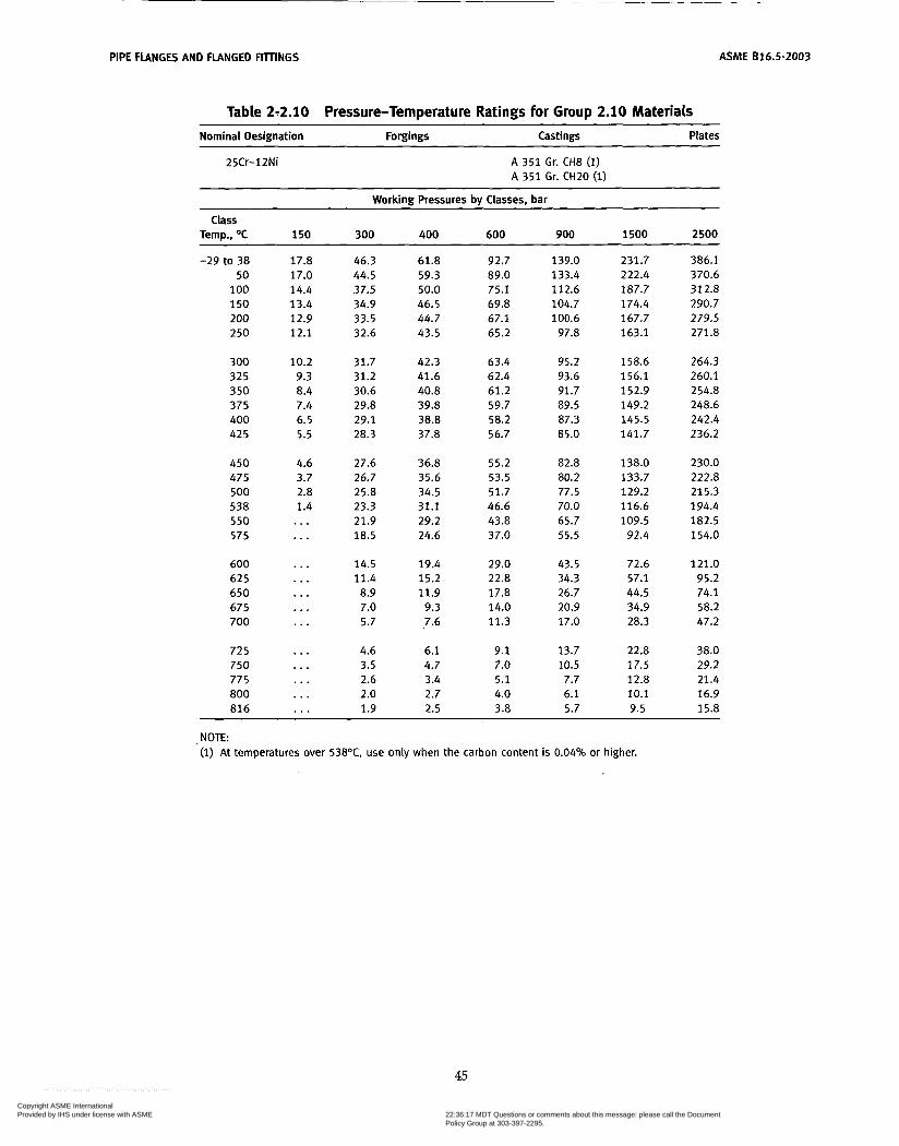
PIPE FLANGES AND FLANGED R m N G S ASME 616.5-2003
Table 2-2.10 Pressure-Temperature Ratings for Group 2.10 Materials Nominal Designation Forgings Castings Plates
25Cr-12Ni A 351 Gr. CH8 (1) A 351 Gr. C H 2 O (1)
Working Pressures by Classes, bar
Temp., OC 1 5 0 300 400 600 900 1500 2500 Class
-29 to 38 50
1 O0 150 200 250
300 325 350 375 400 425
450 475 500 538 550 575
600 625 650 675 700
725 750 775 ao0 816
17.8 17.0 14.4 13.4 12.9 12.1
10.2 9.3
7.4 6.5 5.5
4.6 3.7
1.4
8.4
2.8
...
...
. . .
. . .
. . .
...
. . .
...
. . .
...
...
. . .
46.3 44.5 37.5 34.9 33.5 32.6
31.7 31.2 30.6
29.1 29.8
28.3
27.6 26.7
23.3 21.9
25.8
18.5
14.5 11.4
7.0 5.7
4.6 3.5 2.6 2.0 1.9
8.9
61.8 59.3 50.0 46.5 44.7 43.5
42.3 41.6 40.8 39.8 38.8 37.8
36.8 35.6 34.5 31.1 29.2 24.6
19.4 15.2 11.9
9.3 7.6
6.1 4.7 3.4 2.7 2.5
92.7
75.1
67.1 65.2
63.4 62.4 61.2 59.7
56.7
55.2 53.5 51.7 46.6
37.0
29.0 22.8 17.8 14.0 11.3
9.1 7.0 5.1 4.0 3.8
89.0
69.8
58.2
43.8
139.0 133.4 112.6 104.7 100.6
97.8
95.2 93.6 91.7 89.5 87.3 85.0
82.8 80.2 77.5 70.0 65.7 55.5
43.5 34.3 26.7 20.9 17.0
13.7 10.5 7.7 6.1 5.7
231.7 222.4
174.4 167.7 163.1
187.7
158.6 156.1 152.9 149.2 145.5 141.7
138.0 133.7 129.2 116.6 109.5 92.4
72.6 57.1 44.5 34.9 28.3
22.8 17.5
10.1 9.5
12.8
386.1 370.6
290.7 279.5
312.8
271.8
264.3 260.1 254.8 248.6 242.4 236.2
230.0
215.3 194.4
154.0
121.0 95.2 74.1
47.2
222.8
182.5
58.2
38.0 29.2 21.4 16.9 15.8
NOTE: (i) At temperatures over 538OC, use only when the carbon content is 0.04% or higher.
45
Copyright ASME International Provided by IHS under license with ASME
Document provided by IHS Licensee=Qatar Petroleum/5943408001, 09/19/200422:36:17 MDT Questions or comments about this message: please call the DocumentPolicy Group at 303-397-2295.
--```,,`,``,,,,`,,``````,,``,`-`-`,,`,,`,`,,`---
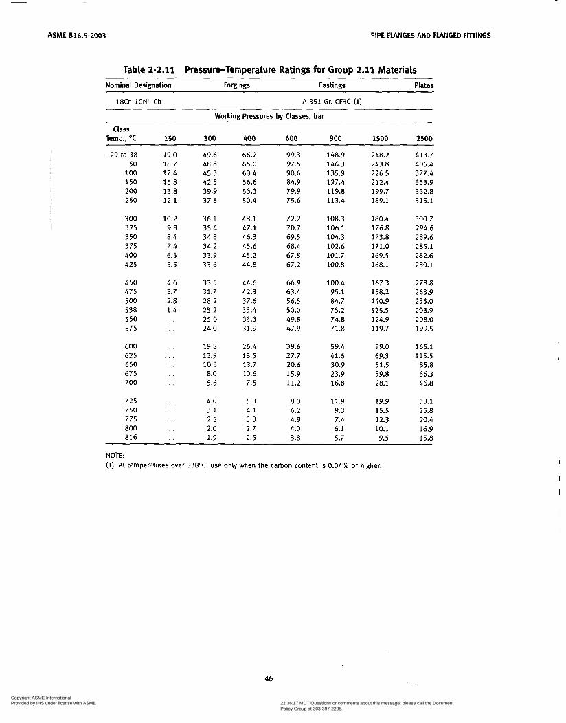
ASME 616.5-2003 PIPE FLANGES AND FLANGED FIllINGS
Table 2-2.1 1 Pressure-Temperature Ratings for Group 2.1 1 Materials Nominal Designation Forgings Castings
~
Plates
18Cr-1ONi-Cb A 351 Gr. CF8C (I)
Working Pressures by Classes, bar
Temp., O C 150 300 400 600 900 1500 2500 Class
-29 to 38 50
100 150 200 250
300 325 350 375 400 425
450 475 500 538 550 575
600 625 650 675 700
725 750 775 800 816
19.0 18.7 17.4 15.8 13.8 12.1
10.2 9.3 8.4 7.4 6.5 5.5
4.6 3.7 2.8 1.4 . . . ...
...
. . .
. . .
...
. . .
. . .
...
. . .
. . .
. . .
49.6 48.8 45.3 42.5 39.9 37.8
36.1 35.4 34.8 34.2 33.9 33.6
33.5 31.7 28.2 25.2 25.0 24.0
19.8 13.9 10.3 8.0 5.6
4.0 3.1 2.5 2.0 1.9
66.2 65.0 60.4 56.6 53.3 50.4
48.1 47.1 46.3 45.6 45.2 44.8
44.6 42.3 37.6 33.4 33.3 31.9
26.4 18.5 13.7 10.6 7.5
5.3 4.1 3.3 2.7 2.5
99.3 97.5 90.6 84.9 79.9 75.6
72.2 70.7 69.5 68.4 67.8 67.2
66.9 63.4 56.5 50.0 49.8 47.9
39.6 27.7 20.6 15.9 11.2
8.0 6.2 4.9 4.0 3.8
148.9 146.3 135.9 127.4 119.8 113.4
108.3 106.1 104.3 102.6 101.7 100.8
100.4 95.1 84.7 75.2 74.8 71.8
59.4 41.6 30.9 23.9 16.8
11.9 9.3 7.4 6.1 5.7
248.2 243.8 226.5 212.4 199.7 189.1
180.4 176.8 173.8 171.0 169.5 168.1
167.3 158.2 140.9 125.5 124.9 119.7
99.0 69.3 51.5 39.8 28.1
19.9 15.5 12.3 10.1 9.5
413.7 406.4 377.4 353.9 332.8 315.1
300.7 294.6 289.6 285.1 282.6 280.1
278.8 263.9 235.0 208.9 208.0 199.5
165.1 115.5
85.8 66.3 46.8
33.1 25.8 20.4 16.9 15.8
NOTE: (1) At temperatures over 538OC. use only when the carbon content is 0.04% or higher,
46
Copyright ASME International Provided by IHS under license with ASME
Document provided by IHS Licensee=Qatar Petroleum/5943408001, 09/19/200422:36:17 MDT Questions or comments about this message: please call the DocumentPolicy Group at 303-397-2295.
--```,,`,``,,,,`,,``````,,``,`-`-`,,`,,`,`,,`---

ASME 816.5-2003 PIPE FLANGES AND FLANGED FITTINGS
Table 2-2.12 Pressure-Temperature Ratings for Group 2.12 Materiais ___ ~~ ~ ~ ~~~ ~
Nominal Designation Forgings Castings Plates
25Cr-20Ni A351 Gr. CK20 (1)
Working Pressures bv Classes. bar ~
Class Temp., O C 150 300 400 600 900 1500 2500
-29 to 38 50
1 O0 150 200 250
300 325 350 375 400 425
450 475 500 538 550 575
600 625 650 675 700
725 750 775 800 816
17.8 17.0 14.4 13.4 12.9 12.1
10.2 9.3 8.4 7.4 6.5 5.5
4.6 3.7 2.8 1.4 ... . . .
...
...
. . .
...
...
. . .
...
...
. . .
. . .
46.3 44.5 37.5 34.9 33.5 32.6
31.7 31.2 30.6 29.8 29.1 28.3
27.6 26.7 25.8 23.3 22.9 21.7
19.4 16.8 14.1 11.5 8.8
6.3 4.5 3.1 2.3 1.9
61.8 59.3 50.0 46.5 44.7 43.5
42.3 41.6 40.8 39.8 38.8 37.8
36.8 35.6 34.5 31.1 30.6 28.9
25.9 22.4 18.8 15.4 11.7
8.5 6.0 4.2 3.1 2.5
92.7 89.0 75.1 69.8 67.1 65.2
63.4 62.4 61.2 59.7 58.2 56.7
55.2 53.5 51.7 46.6 45.9 43.3
38.8 33.7 28.1 23.0 17.5
12.7 8.9 6.3 4.6 3.8
139.0 133.4 112.6 104.7 100.6
97.8
95.2 93.6 91.7 89.5 87.3 85.0
82.8 80.2 77.5 70.0 68.8 65.0
58.2 50.5 42.2 34.6 26.3
19.0 13.4 9.4 6.9 5.7
231.7 222.4 187.7 174.4 167.7 163.1
158.6 156.1 152.9 149.2 145.5 141.7
138.0 133.7 129.2 116.6 114.7 108.3
97.1 84.1 70.4 57.6 43.8
31.7 22.3 15.7 11.4
9.5
386.1 370.6 312.8 290.7 279.5 271.8
264.3 260.1 254.8 248.6 242.4 236.2
230.0 222.8 215.3 194.4 191.2 180.4
161.8 140.2 117.3
96.0 73.0
52.9 37.2 26.2 19.1 15.8
NOTE: (1) At temperatures over 538OC. use only when the carbon content is 0.04% or higher.
47
Copyright ASME International Provided by IHS under license with ASME
Document provided by IHS Licensee=Qatar Petroleum/5943408001, 09/19/200422:36:17 MDT Questions or comments about this message: please call the DocumentPolicy Group at 303-397-2295.
--```,,`,``,,,,`,,``````,,``,`-`-`,,`,,`,`,,`---
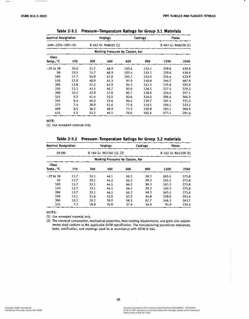
ASME 816.5-2003 PIPE FLANGES AND FLANGED FlïTINGS
Table 2-3.1 Pressure-Temperature Ratings for Group 3.1 Materials
Nominal Designation Forgings Castings Plates
35Ni-35Fe-lOCr-Cb B 462 Gr. NO8020 (1) B 463 Gr. NO8020 (1) ~~ ~~~ ~~~~ ~~~ -
Working Pressures by Classes, bar
Temp., O C 150 300 400 600 900 1500 2500
-29 to 38 20.0 51.7 68.9 103.4 155.1 258.6 430.9 50 19.5 51.7 68.9 103.4 155.1 258.6 430.9
100 17.7 50.9 67.8 101.7 152.6 254.4 423.9 150 15.8 48.9 65.3 97.9 146.8 244.7 407.8 200 13.8 47.2 62.9 94.3 141.5 235.8 392.9 250 12.1 45.5 60.7 91.0 136.5 227.5 379.2 300 10.2 42.9 57.0 85.7 128.6 214.4 357.1 325 9.3 41.4 55.0 82.6 124.0 206.6 344.3 350 8.4 40.3 53.6 80.4 120.7 201.1 335.3 375 7.4 38.9 51.6 77.6 116.5 194.1 323.2 400 6.5 36.5 48.9 73.3 109.8 183.1 304.9 425 5.5 35.2 46.5 70.0 105.1 175.1 291.6
Class
~ ~~ ~ ~~ ~ ~ ~~
NOTE: (1) Use annealed material only.
Table 2-3.2 Pressure-Temperature Ratings for Group 3.2 materials
Nominal Designation Forgings Castings Plates
99.ONi B 160 Gr. NO2200 ( l ) , (2) B 162 Gr. NO2200 ( i)
Working Pressures by Classes, bar
Class Temp., O C 150 300 400 600 900 1500 2500
-29 to 38 12.7 50 12.7
1 O0 12.7 150 12.7 200 12.7 250 12.1 300 10.2 325 7.2
33.1 44.1 33.1 44.1 33.1 44.1 33.1 44.1 33.1 44.1 31.6 42.1 29.2 39.0 18.8 25.0
66.2 66.2 66.2 66.2 66.2 63.2 58.5 37.6
99.3 99.3 99.3 99.3 99.3 94.8 87.7 56.4
165.5 165.5 165.5 165.5 165.5 158.0 146.2
93.9
275.8 275.8 275.8 275.8 275.8 263.4 243.7 156.5
NOTES: (i) Use annealed material only. (2) The chemical composition, mechanical properties, heat treating requirements, and grain size require-
ments shall conform to the applicable ASTM specification. The manufacturing procedures tolerances, tests, certification, and markings shall be in accordance with ASTM B 564.
48
Copyright ASME International Provided by IHS under license with ASME
Document provided by IHS Licensee=Qatar Petroleum/5943408001, 09/19/200422:36:17 MDT Questions or comments about this message: please call the DocumentPolicy Group at 303-397-2295.
--```,,`,``,,,,`,,``````,,``,`-`-`,,`,,`,`,,`---
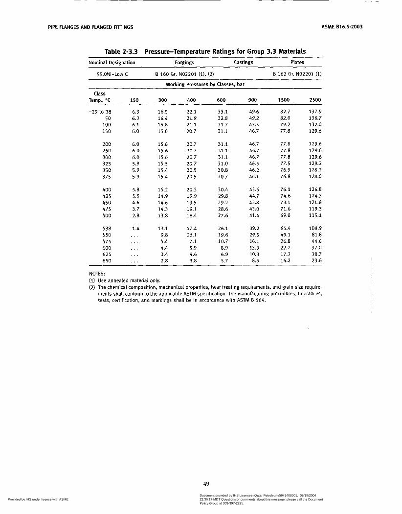
PIPE FLANGES AND FLANGED FITíINGS ASME 816.5-2003
Table 2-3.3 Pressure-Temperature Ratings for Group 3.3 Materials Nominal Designation Forgings Castings Plates
99.ONi-Low C 6 160 Gr. NO2201 (11, (2) B 162 Gr. NO2201 (1)
Working Pressures by Classes, bar
Temo.. O C 150 300 400 600 900 3 500 2500 Class
-29 to 38 6.3 50 6.3
100 6.1 150 6.0
200 6.0 250 6.0 300 6.0 325 5.9 350 5.9 375 5.9
400 5.8 425 5.5 450 4.6 475 3.7 500 2.8
538 1.4 550 ... 575 . . . 600 ... 625 ... 650 . . .
16.5 16.4 15.8 15.6
15.6 15.6 15.6 15.5 15.4 15.4
15.2 14.9 14.6 14.3 13.8
13.1 9.8 5.4 4.4 3.4 2.8
22.1 21.9 21.1 20.7
20.7 20.7 20.7 20.7 20.5 20.5
20.3 19.9 19.5 19.1 18.4
17.4 13.1
7.1 5.9 4.6 3.8
33.1 32.8 31.7 31.1
31.1 31.1 31.1 31.0 30.8 30.7
30.4 29.8 29.2 28.6 27.6
26.1 19.6 10.7 8.9 6.9 5.7
49.6 49.2 47.5 46.7
46.7 46.7 46.7 46.5 46.2 46.1
45.6 44.7 43.8 43.0 41.4
39.2 29.5 16.1 13.3 10.3 8.5
82.7 82.0 79.2 77.8
77.8 77.8 77.8 77.5 76.9 76.8
76.1 74.6 73.1 71.6 69.0
65.4 49.1 26.8 22.2 17.2 14.2
137.9 136.7 132.0 129.6
129.6 129.6 129.6 129.2 128.2 128.0
126.8 124.3 121.8 119.3 115.1
108.9 81.8 44.6 37.0 28.7 23.6
~
NOTES: (i) Use annealed material only. (2) The chemical composition, mechanical properties, heat treating requirements, and grain size require-
ments shall conform to the applicable ASTM specification. The manufacturing procedures, tolerances, tests, certification, and markings shall be in accordance with ASTM B 564.
49
Copyright ASME International Provided by IHS under license with ASME
Document provided by IHS Licensee=Qatar Petroleum/5943408001, 09/19/200422:36:17 MDT Questions or comments about this message: please call the DocumentPolicy Group at 303-397-2295.
--```,,`,``,,,,`,,``````,,``,`-`-`,,`,,`,`,,`---

ASME 816.5-2003 PIPE FLANGES AND FLANGED FITTINGS
Table 2-3.4 Pressure-Temperature Ratings for Group 3.4 Materials ~ ~- -~ ~~~~~~~
Nominal Designation Forgings Castings Plates
67Ni-30Cü
67Ni-30CU-S
B 564 Gr. NO4400 (i)
B 164 Gr. NO4405 (l), (2)
B 127 Gr. NO4400 (1)
M r k i n g Pressures by Classes, bar
Class Temo.. O C 150 300 400 600 900 1500 2500
-29 to 38 50 100 150 200 250 300 325 350 375 400 425 450 475
15.9 41.4 55.2 15.4 40.2 53.7 13.8 35.9 47.9 12.9 33.7 45.0 12.5 32.7 43.6 12.1 32.6 43.5 10.2 32.6 43.5 9.3 32.6 43.5 8.4 32.6 43.4 7.4 32.4 43.2
5.5 31.6 42.2 4.6 26.9 35.9 3.7 20.8 27.7
6.5 32.1 42.8
82.7
71.9 67.5 65.4 65.2 65.2 65.2 65.1
64.2 63.3 53.8 41.5
80.5
64.8
124.1 120.7 107.8 101.2
98.1 97.8 97.8
97.7 97.2 96.2 94.9 80.7 62.3
97.8
206.8
168.7
201.2 179.7
163.5 163.0 163.0 163.0
161.9 160.4 158.2 134.5 103.8
162.8
344.7 335.3 299.5
272.4 271.7 271.7 271.7 271.3 269.9 267.4 263.6 224.2 173.0
281.1
NOTES: (i) Use annealed material only. (2) The chemical composition, mechanical properties, heat treating requirements, and grain size require-
ments shall conform to the applicable ASTM specification. The manufacturing procedures, tolerances, tests, certification, and markings shall be in accordance with ASTM B 564.
50 Copyright ASME International Provided by IHS under license with ASME
Document provided by IHS Licensee=Qatar Petroleum/5943408001, 09/19/200422:36:17 MDT Questions or comments about this message: please call the DocumentPolicy Group at 303-397-2295.
--```,,`,``,,,,`,,``````,,``,`-`-`,,`,,`,`,,`---

PIPE FLANGES AND FLANGED FITTINGS ASME 816.5-2003
Table 2-3.5 Pressure-Temperature Ratings for Group 3.5 Materials Nominal Designation Forgings Castings Plates
72Ni-15Cr-8Fe B 564 Gr. NO6600 (1) B i 6 8 Gr. NO6600 ( i)
Working Pressures by Classes, bar
Class Tem. . OC 150 300 400 600 900 1500 2500
-29 to 38 50
100 150 200
20.0 51.7 19.5 51.7 17.7 51.5 15.8 50.3 13.8 48.6
68.9 68.9 68.7
64.8 66.8
103.4 103.4 103.0 100.3 97.2
155.1 155.1 154.6 150.6 145.8
258.6
250.8
258.6 257.6
243.4
430.9 430.9 429.4
405.4 418.2
2 50 300 325 3 50 375
12.1 46.3 10.2 42.9
9.3 41.4 8.4 40.3 7.4 38.9
61.7 57.0 55.0 53.6 51.6
92.7 85.7 82.6 80.4 77.6
139.0
124.0 120.7 116.5
128.6 231.8 214.4 206.6 201.1 194.1
386.2 357.1 344.3 335.3 323.2
400 425 450 475 500
6.5 36.5 5.5 35.2 4.6 33.7 3.7 31.7 2.8 28.2
48.9 46.5 45.1 42.3 37.6
73.3 70.0 67.7 63.4 56.5
109.8 105.1 101.4
95.1 84.7
183.1
158.2
175.1 169.0
140.9
304.9 291.6
263.9 235.0
281.8
538 550 575 600 625 650
1.4 16.5 . . . 13.9 . . . 9.4 . . . 6.6 . . . 5.1 . . . 4.7
22.1
12.6
6.8 6.3
18.6
8.9
33.1 27.9
13.3 10.3 9.5
18.9
49.6 41.8 28.3 19.9 15.4 14.2
82.7 69.7 47.2 33.2 25.7 23.6
137.9 116.2
55.3
39.4
78.6
42.8
~
NOTE: (1) Use annealed material only.
51 Copyright ASME International Provided by IHS under license with ASME
Document provided by IHS Licensee=Qatar Petroleum/5943408001, 09/19/200422:36:17 MDT Questions or comments about this message: please call the DocumentPolicy Group at 303-397-2295.
--```,,`,``,,,,`,,``````,,``,`-`-`,,`,,`,`,,`---
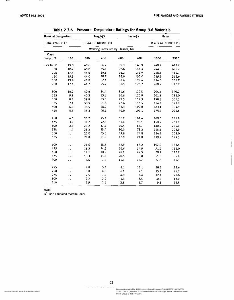
ASME B16.5-2003 PIPE FLANGES AND FLANGED FITTINGS
Table 2-3.6 Pressure-Temperature Ratings for Group 3.6 Materials Nominal Designation Forgings Castings Plates
33Ni-42Fe-21Cr B 564 Gr. NO8800 (1) B 409 Gr. NO8800 (1) ~ ~~~ ~~ ~ ~
Working Pressures by Classes, bar
Temp.. O C 150 300 400 600 900 1500 2500 class
-29 to 38 19.0 49.6 66.2 50 18.7 48.8 65.1
100 17.5 45.6 60.8 150 15.8 44.0 58.7 200 13.8 42.8 57.1 250 12.1 41.7 55.7
300 10.2 40.8 54.4 325 9.3 40.3 53.8 350 8.4 39.8 53.0 375 7.4 38.9 51.6 400 6.5 36.5 48.9 42 5 5.5 35.2 46.5
450 4.6 33.7 45.1 475 3.7 31.7 42.3 500 2.8 28.2 37.6 538 1.4 25.2 33.4 550 ... 25.0 33.3 575 . . . 24.0 31.9
600 ... 21.6 28.6 62 5 . . . 18.3 24.3 650 . . . 14.1 18.9 675 ... 10.3 13.7 700 . . . 5.6 7.4
725 ... 4.0 5.4 750 . . . 3.0 4.0 775 ... 2.5 3.3 800 ... 2.2 2.9 816 . . . 1.9 2.5
99.3 97.6 91.2 88.0 85.6 83.5
81.6 80.6 79.5 77.6 73.3 70.0
67.7 63.4 56.5 50.0 49.8 47.9
42.9 36.6 28.1 20.5 11.1
8.1 6.1 4.9 4.3 3.8
148.9 146.4 136.9 132.0 128.4 125.2
122.5 120.9 119.3 116.5 109.8 105.1
101.4 95.1 84.7 75.2 74.8 71.8
64.2 54.9 42.5 30.8 16.7
12.1 9.1 7.4 6.5 5.7
248.2 244.0 228.1 219.9 214.0 208.7
204.1 201.6 198.8 194.1 183.1 175.1
169.0 158.2 140.9 125.5 124.9 119.7
107.0 91.2 70.7 51.3 27.8
20.1 15.1 12.4 10.8 9.5
413.7 406.7 380.1 366.6 356.7 347.9
340.2 336.0 331.3 323.2 304.9 291.6
281.8 263.9 235.0 208.9 208.0 199.5
178.5 152.0 117.7 85.6 46.3
33.6 25.2 20.6 18.0 15.8
NOTE: (i) Use annealed material only.
52
Copyright ASME International Provided by IHS under license with ASME
Document provided by IHS Licensee=Qatar Petroleum/5943408001, 09/19/200422:36:17 MDT Questions or comments about this message: please call the DocumentPolicy Group at 303-397-2295.
--```,,`,``,,,,`,,``````,,``,`-`-`,,`,,`,`,,`---
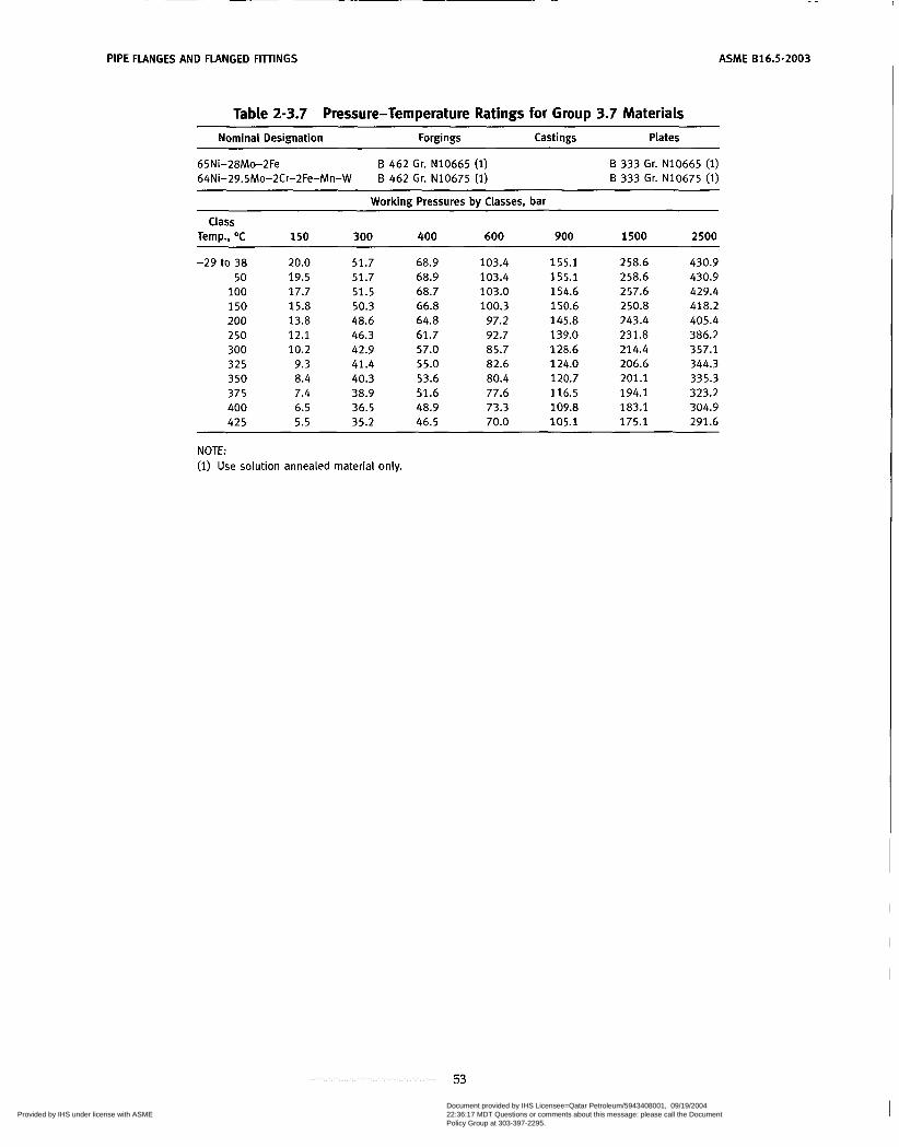
PIPE FLANGES AND FLANGED FITINGS ASME 816.5-2003
Table 2-3.7 Pressure-Temperature Ratings for Group 3.7 Materials ~~
Nominal Designation ~~~ ~
Forgings Castings Plates
65Ni-28Mo-2Fe 64Ni-29.5Mo-2Cr-2Fe-Mn-W
B 462 Gr. N10665 ( i) B 462 Gr. N10675 (1)
B 333 Gr. N10665 (1) B 333 Gr. N10675 (1)
Working Pressures by Classes, bar
Temp., OC 150 300 400 600 900 1500 2500
-29 to 38 20.0 51.7 68.9 103.4 155.1 258.6 430.9 50 19.5 51.7 68.9 103.4 155.1 258.6 430.9
100 17.7 51.5 68.7 103.0 154.6 257.6 429.4 150 15.8 50.3 66.8 100.3 150.6 250.8 418.2 200 13.8 48.6 64.8 97.2 145.8 243.4 405.4 250 12.1 46.3 61.7 92.7 139.0 231.8 386.2 300 10.2 42.9 57.0 85.7 128.6 214.4 357.1 325 9.3 41.4 55.0 82.6 124.0 206.6 344.3 350 8.4 40.3 53.6 80.4 120.7 201.1 335.3 375 7.4 38.9 51.6 77.6 116.5 194.1 323.2 400 6.5 36.5 48.9 73.3 109.8 183.1 304.9 425 5.5 35.2 46.5 70.0 105.1 175.1 291.6
Class
NOTE: (1) Use solution annealed material only.
53
Copyright ASME International Provided by IHS under license with ASME
Document provided by IHS Licensee=Qatar Petroleum/5943408001, 09/19/200422:36:17 MDT Questions or comments about this message: please call the DocumentPolicy Group at 303-397-2295.
--```,,`,``,,,,`,,``````,,``,`-`-`,,`,,`,`,,`---
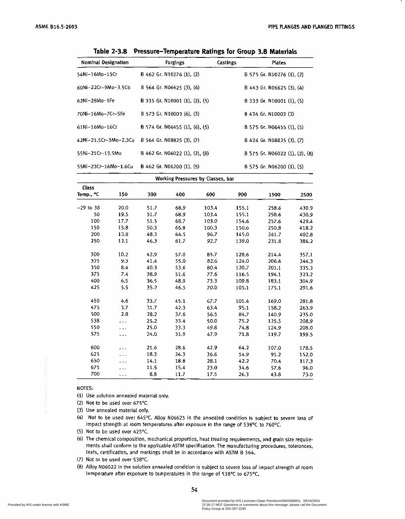
ASME 816.5-2003 PIPE FLANGES AND FLANGED FIllINGS
Table 2-3.8 Pressure-Temperature Ratings for Group 3.8 Materiais Nominal Designation Forgings Castings Plates
54Ni-16Mo-15Cr
60Ni-22Cr-9Mo-3.5Cb
62Ni-28Mo-5Fe
70Ni-16Mo-7Cr-5Fe
61Ni-16Mo-16Cr
B 462 Gr. N10276 (i), (2)
B 564 Gr. NO6625 (3), (4)
B 335 Gr. N10001 (11, (2). (5)
B 573 Gr. N10003 (6), (3)
B 574 Gr. NO6455 (i), (6). (5)
B 575 Gr. N10276 (i), (2)
B 443 Gr. NO6625 (31, (4)
B 333 Gr. N10001 (l), (5)
8 434 Gr. N10003 (3)
B 575 Gr. NO6455 (i), (5)
42Ni-21.5Cr-3Mo-2.3Cu
55Ni-21Cr-13.5Mo
55Ni-23Cr-16Mo-1.6Cu
B 564 Gr. NO8825 (3), (7)
B 462 Gr. NO6022 (l), (2), (8)
B 462 Gr. NO6200 (i), (5)
B 424 Gr. NO8825 (3), (7)
B 575 Gr. NO6022 (1). (21, (8)
B 575 Gr. NO6200 (i), (5)
Working Pressures bv Classes. bar ~~
Class Temp., O C 150 300 400 600 900 1500 2500
-29 to 38 20.0 51.7 68.9 103.4 155.1 258.6 430.9 50 19.5 51.7 68.9 103.4 155.1 258.6 430.9
100 17.7 51.5 68.7 103.0 154.6 257.6 429.4 150 15.8 50.3 66.8 100.3 150.6 250.8 418.2 200 13.8 48.3 64.5 96.7 145.0 241.7 402.8 250 12.1 46.3 61.7 92.7 139.0 231.8 386.2
300 10.2 42.9 57.0 85.7 128.6 214.4 357.1 325 9.3 41.4 55.0 82.6 124.0 206.6 344.3 350 8.4 40.3 53.6 80.4 120.7 201.1 335.3 375 7.4 38.9 51.6 77.6 116.5 194.1 323.2 400 6.5 36.5 48.9 73.3 109.8 183.1 304.9 425 5.5 35.2 46.5 70.0 105.1 175.1 291.6
450 4.6 33.7 45.1 67.7 101.4 169.0 281.8 475 3.7 31.7 42.3 63.4 95.1 158.2 263.9 500 2.8 28.2 37.6 56.5 84.7 140.9 235.0 538 ... 25.2 33.4 50.0 75.2 125.5 208.9 550 . . . 25.0 33.3 49.8 74.8 124.9 208.0 575 . . . 24.0 31.9 47.9 71.8 119.7 199.5
600 ... 21.6 28.6 42.9 64.2 107.0 178.5 625 . . . 18.3 24.3 36.6 54.9 91.2 152.0 650 ... 14.1 18.8 28.1 42.2 70.4 117.3 675 ... 11.5 15.4 23.0 34.6 57.6 96.0 700 . . . 8.8 11.7 17.5 26.3 43.8 73.0
NOTES: ( i ) Use solution annealed material only. (2) Not to be used over 675OC. (3) Use annealed material only. (4) Not to be used over 645OC. Alloy NO6625 in the annealed condition is subject to severe loss of
(5) Not to be used over 425OC. (6) The chemical composition, mechanical properties, heat treating requirements, and grain size require-
ments shall conform to the applicable ASTM specification. The manufacturing procedures, tolerances, tests, certification, and markings shall be in accordance with ASTM B 564.
(7) Not to be used over 538OC. (8) Alloy NO6022 in the solution annealed condition is subject to severe loss of impact strength at room
temperature after exposure to temperatures in the range of 538OC to 675OC.
impact strength at room temperatures after exposure in the range of 538OC to 760OC.
54 Copyright ASME International Provided by IHS under license with ASME
Document provided by IHS Licensee=Qatar Petroleum/5943408001, 09/19/200422:36:17 MDT Questions or comments about this message: please call the DocumentPolicy Group at 303-397-2295.
--```,,`,``,,,,`,,``````,,``,`-`-`,,`,,`,`,,`---
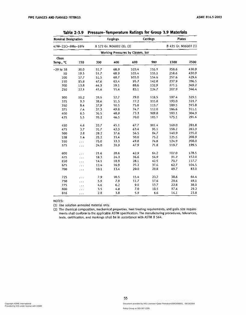
PIPE FLANGES AND FLANGED FIllINGS ASME 816.5-2003
Table 2-3.9 Pressure-Temperature Ratings for Group 3.9 Materials Nominal Designation Forgings Castings Plates
47Ni-22Cr-gMo-18Fe Ei 572 Gr. NO6002 (l), (2) B 435 Gr. NO6002 ( i )
Working Pressures by Classes, bar
Temp., O C 150 300 400 600 900 1500 2500 Class
-29 to 38 50
100 150 200 250
300 325 350 375 400 425
450 475 500 538 550 575
600 625 650 675 700
725 750 775 800 816
20.0 19.5 17.7 15.8 13.8 12.1
10.2 9.3 8.4 7.4 6.5 5.5
4.6 3.7 2.8 1.4 ... . . .
...
...
. . .
. . .
...
...
...
. . .
. . .
...
51.7 51.7 51.5 47.6 44.3 41.6
39.5 38.6 37.9 37.3 36.5 35.2
33.7 31.7 28.2 25.2 25.0 24.0
21.6 18.3 14.1 12.4 10.1
7.9 5.9 4.6 3.5 2.8
68.9 68.9 68.7 63.4 59.1 55.4
52.7 51.5 50.5 49.8 48.9 46.5
45.1 42.3 37.6 33.4 33.3 31.9
28.6 24.3 18.9 16.9 13.4
10.5 7.9 6.2 4.8 3.8
103.4 103.4 103.0
95.2 88.6 83.1
79.0 77.2 75.8 74.7 73.3 70.0
67.7 63.4 56.5 50.0 49.8 47.9
42.9 36.6 28.1 25.2 20.0
15.4 11.7 9.0 7.0 5.9
155.1 155.1 154.6 142.8 132.9 124.7
118.5 115.8 113.7 112.0 109.8 105.1
101.4 95.1 84.7 75.2 74.8 71.8
64.2 54.9 42.5 37.6 29.8
23.2 17.6 13.7 10.5 8.6
258.6 258.6 257.6 237.9 221.5 207.9
197.4 193.0 189.5 186.6 183.1 175.1
169.0 158.2 140.9 125.5 124.9 119.7
107.0 91.2 70.7 62.7 49.7
38.6 29.6 22.8 17.4 14.1
430.9 430.9 429.4 396.5 369.2 346.4
329.1 321.7 315.8 311.1 304.9 291.6
281.8 263.9 235.0 208.9 208.0 199.5
178.5 152.0 117.7 104.5
83.0
64.4 49.1 38.0 29.2 23.8
NOTES: (1) Use solution annealed material only. (2) The chemical composition, mechanical properties, heat treating requirements, and grain size require-
ments shall conform to the applicable ASTM specification. The manufacturing procedures, tolerances, tests, certification, and markings shall be in accordance with ASTM Ei 564.
55 Copyright ASME International Provided by IHS under license with ASME
Document provided by IHS Licensee=Qatar Petroleum/5943408001, 09/19/200422:36:17 MDT Questions or comments about this message: please call the DocumentPolicy Group at 303-397-2295.
--```,,`,``,,,,`,,``````,,``,`-`-`,,`,,`,`,,`---
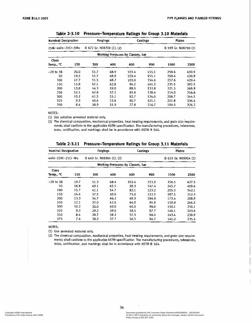
ASME 816.5-2003 PIPE FLANGES AND FLANGED FIìlINGS
Table 2-3.10 Pressure-Temperature Ratings for Group 3.10 Materials Nominal Designation Forgings Castings Plates
25Ni-46Fe-21Cr-5Mo B 672 Gr. NO8700 ( i ) , (2) B 599 Gr. NO8700 (1)
Workinn Pressures bv Classes, bar
Class Temp., O C 150 300 400 600 900 1500 2500
-29 to 38 50
100 150 200 250 300 325 350
20.0 19.5 17.7 15.8 13.8 12.1 10.2
9.3 8.4
51.7 68.9 103.4 155.1 258.6 430.9 51.7 68.9 103.4 155.1 258.6 430.9 51.5 68.7 103.0 154.6 257.6 429.4 47.1 62.8 94.2 141.3 235.5 392.5 44.3 59.0 88.5 132.8 221.3 368.9 42.8 57.1 85.6 128.4 214.0 356.6 41.3 55.1 82.7 124.0 206.7 344.5 40.4 53.8 80.7 121.1 201.8 336.4 38.9 51.9 77.8 116.7 194.5 324.2
NOTES: (1) Use solution annealed material only. (2) The chemical composition, mechanical properties, heat treating requirements, and grain size'require-
ments shall conform to the applicable ASTM specification. The manufacturing procedures, tolerances, tests, certification, and markings shall be in accordance with ASTM 8 564.
Table 2-3.1 1 Pressure-Temperature Ratings for Group 3.11 Materials
Nominal Designation Forgings Castings Plates
44Fe-25Ni-21Cr-Mo B 649 Gr. NO8904 (i), (2) B 625 Gr. NO8904 (1)
Working Pressures by Classes, bar
Temp., O C 150 300 400 600 900 1500 2500 Class
-29 to 38 19.7 50 18.8
100 15.7 150 14.4 200 13.3 250 12.1 300 10.2 325 9.3 350 8.4 375 7.4
51.3 68.4 49.1 65.5 41.1 54.7 37.5 50.0 34.7 46.2 32.0 42.6 30.0 40.0 29.2 39.0 28.7 38.2 28.2 37.7
102.6 153.9 256.5 427.5 98.3 147.4 245.7 409.6 82.1 123.2 205.3 342.1 75.0 112.5 187.5 312.5 69.3 104.0 173.4 288.9 64.0 95.9 159.9 266.5 60.0 90.0 150.1 250.1 58.5 87.7 146.1 243.6 57.3 86.0 143.4 238.9 56.5 84.7 141.2 235.4
NOTES: (1) Use annealed materiel only. (2) The chemical composition, mechanical properties, heat treating requirements, and grain size require-
ments shall conform to the applicable ASTM specification. The manufacturing procedures, tolerances, tests, certification, and markings shall be in accordance with ASTM B 564.
56 Copyright ASME International Provided by IHS under license with ASME
Document provided by IHS Licensee=Qatar Petroleum/5943408001, 09/19/200422:36:17 MDT Questions or comments about this message: please call the DocumentPolicy Group at 303-397-2295.
--```,,`,``,,,,`,,``````,,``,`-`-`,,`,,`,`,,`---
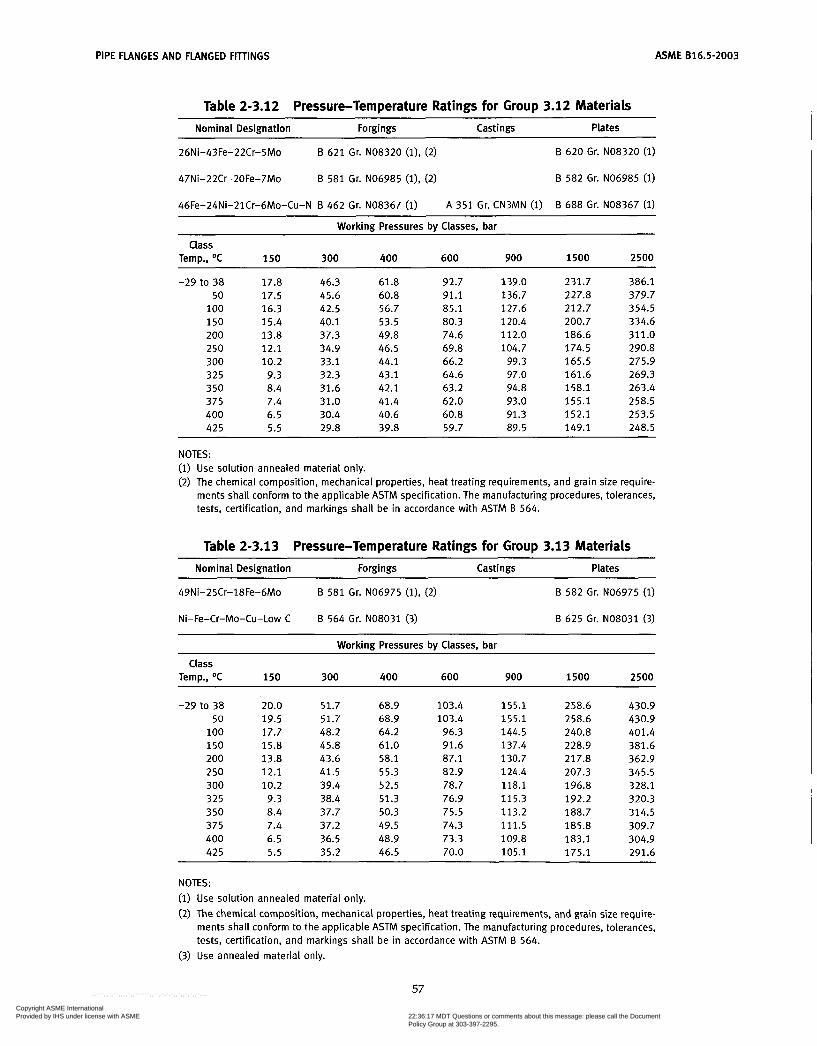
PIPE FLANGES AND FLANGED FITTINGS ASME B16.5-2003
Table 2-3.12 Pressure-Temperature Ratings for Group 3.12 Materials ~
Nominal Designation Forgings Cast i ngs Plates
26Ni-43Fe-22Cr-5Mo
47Ni-22Cr-20Fe-7Mo
46Fe-24Ni-21Cr-6Mo-Cu-N B 462 Gr. NO8367 (1)
B 621 Gr. NO8320 (1). (2)
B 581 Gr. NO6985 (i), (2)
B 620 Gr. NO8320 (i)
B 582 Gr. NO6985 (i)
B 688 Gr. NO8367 (i) A 351 Gr. CN3MN (1)
Working Pressures by Classes, bar
Class Temp., O C 150 300 400 600 900 1500 2500
-29 to 38 17.8 46.3 50 17.5 45.6
100 16.3 42.5 150 15.4 40.1 200 13.8 37.3 250 12.1 34.9 300 10.2 33.1 325 9.3 32.3 350 8.4 31.6 375 7.4 31.0 400 6.5 30.4 425 5.5 29.8
61.8 60.8 56.7 53.5 49.8 46.5 44.1 43.1 42.1 41.4 40.6 39.8
92.7 91.1 85.1 80.3 74.6 69.8 66.2 64.6 63.2 62.0 60.8 59.7
139.0 136.7 127.6 120.4 112.0 104.7
99.3 97.0 94.8 93.0 91.3 89.5
231.7 227.8 212.7 200.7 186.6 174.5 165.5 161.6 158.1 155.1 152.1 149.1
386.1 379.7 354.5 334.6 311.0 290.8 275.9 269.3 263.4 258.5 253.5 248.5
~ ~~
NOTES: (1) Use solution annealed material only. (2) The chemical composition, mechanical properties, heat treating requirements, and grain size require-
ments shall conform to the applicable ASTM specification. The manufacturing procedures, tolerances, tests, certification, and markings shall be in accordance with ASTM B 564.
Table 2-3.13 Pressure-Temperature Ratings for Group 3.13 Materiais Nominal Designation Forgings Castings Plates
~ _ _ _ _ _ ~~
49Ni-25Cr-18Fe-6Mo B 581 Gr. NO6975 (i), (2)
~ ~
B 582 Gr. NO6975 (1)
Ni-Fe-Cr-Mo-Cu-Low C B 564 Gr. NO8031 (3) B 625 Gr. NO8031 (3)
Working Pressures by Classes, bar
Class Temp., O C 150 300 400 600 900 1500 2500
-29 to 38 50
100 150 200 250 300 325 350 375 400 425
20.0 51.7 19.5 51.7 17.7 48.2 15.8 45.8 13.8 43.6 12.1 41.5 10.2 39.4 9.3 38.4 8.4 37.7 7.4 37.2 6.5 36.5 5.5 35.2
68.9 68.9 64.2 61.0 58.1 55.3 52.5 51.3 50.3 49.5 48.9 46.5
103.4 103.4 96.3 91.6 87.1 82.9 78.7 76.9 75.5 74.3 73.3 70.0
155 .1 155.1 144.5 137.4 130.7 124.4 118.1 115.3 113.2 111.5 109.8 105.1
258.6 258.6 240.8 228.9 217.8 207.3 196.8 192.2 188.7 185.8 183.1 175.1
430.9 430.9 401.4 381.6 362.9 345.5 328.1 320.3 314.5 309.7 304.9 291.6
NOTES: (1) Use solution annealed material only. (2) The chemical composition, mechanical properties, heat treating requirements, and grain size require-
ments shall conform to the applicable ASTM specification. The manufacturing procedures, tolerances, tests, certification, and markings shall be in accordance with ASTM B 564.
(3) Use annealed material only.
57 Copyright ASME International Provided by IHS under license with ASME
Document provided by IHS Licensee=Qatar Petroleum/5943408001, 09/19/200422:36:17 MDT Questions or comments about this message: please call the DocumentPolicy Group at 303-397-2295.
--```,,`,``,,,,`,,``````,,``,`-`-`,,`,,`,`,,`---

ASME 816.5-2003 PIPE FLANGES AND FLANGED FIllINGS
Table 2-3.14 Pressure-Temperature Ratings for Group 3.14 Materials
Nominal Designation Forgings Castings Plates
47Ni-22Cr-19Fe-6Mo
40Ni-29Cr-15Fe-5Mo
E3 581 Gr. NO6007 (l), (2)
E3 462 Gr. NO6030 (i), (3)
B 582 Gr. NO6007 (i)
B 582 Gr. NO6030 (l), (3) ~ ~
Working Pressures by Classes, bar
Temp., O C 150 300 400 600 900 1500 2500
-29 to 38 19.0 49.6 66.2 99.3 148.9 248.2 413.7 50 18.6 48.6 64.7 97.1 145.7 242.8 404.6
1 O0 17.0 44.3 59.0 88.6 132.8 221.4 369.0 150 15.8 41.3 55.1 82.6 124.0 206.6 344.3 200 13.8 39.1 52.1 78.2 117.3 195.4 325.7
Class
2 50 12.1 37.4 49.9 74.8 112.2 187.0 311.6 300 10.2 36.1 48.2 72.2 108.3 180.6 300.9 325 9.3 35.6 47.4 71.1 106.7 177.9 296.4 350 8.4 35.2 46.9 70.3 105.5 175.8 293.1 375 7.4 34.9 46.5 69.7 104.6 174.3 290.6
400 6.5 34.6 46.1 69.2 103.7 172.9 288.1 425 5.5 34.4 45.9 68.9 103.3 172.1 286.9 450 4.6 33.7 45.1 67.7 101.4 169.0 281.8 475 3.7 31.7 42.3 63.4 95.1 158.2 263.9 500 2.8 28.2 37.6 56.5 84.7 140.9 235.0 538 1.4 25.2 33.4 50.0 75.2 125.5 208.9
NOTES: (1) Use solution annealed material only. (2) The chemical composition, mechanical properties, heat treating requirements, and grain size require-
ments shall conform to the applicable ASTM specification. The manufacturing procedures, tolerances, tests, certification, and markings shall be in accordance with ASTM B 564.
(3) Not to be used over 425OC.
58
Copyright ASME International Provided by IHS under license with ASME
Document provided by IHS Licensee=Qatar Petroleum/5943408001, 09/19/200422:36:17 MDT Questions or comments about this message: please call the DocumentPolicy Group at 303-397-2295.
--```,,`,``,,,,`,,``````,,``,`-`-`,,`,,`,`,,`---

PIPE FLANGES AND FLANGED FITTINGS ASME 816.5-2003
Table 2-3.15 Pressure-Temperature Ratings for Group 3.15 Materials Nominal Designation Forgings Castings Plates
33Ni-42Fe-21Cr B 564 Gr. No8810 (i) B 409 Gr. ~ 0 8 8 1 0 (i)
Working Pressures by Classes, bar
Class Temp., OC 150 300 400 600 900 1500 2500
-29 to 38 50
100 150 200 250
300 325 350 375 400 425
450 475 500
550 575
600 625 650 675 700
725 750 775
816
538
ao0
15.9 15.6 14.5 13.7 13.0 12.1
10.2 9.3
7.4 6.5 5.5
4.6 3.7
1.4
8.4
2.8
. . .
...
...
...
...
. . .
...
. . .
...
...
. . .
...
41.4 40.6
35.9 33.9 32.3
30.7 30.1 29.4 28.7
27.7
27.2
26.3 25.2 25.0 24.0
21.6
14.1 12.4 10.1
7.9 5.9 4.6 3.5
37.8
28.3
26.8
18.3
2.8
55.2 54.2 50.4 47.8 45.2 43.0
41.0 40.1 39.2
37.7 36.9
36.3 35.7 35.1 33.4 33.3 31.9
38.3
28.6
18.9 24.3
16.9 13.4
10.5 7.9 6.2
3.8 4.8
82.7 81.3 75.6 71.7 67.9 64.5
61.5 60.1 58.8 57.4 56.5 55.3
54.4 53.5 52.6 50.0
47.9
42.9 36.6
25.2 20.0
15.4 11.7
9.0 7.0 5.9
49.8
28.1
124.1 121.9 113.4 107.6 101.8 96.8
92.2 90.2 88.3 86.2 84.8 83.0
81.7
79.0 75.2
80.3
74.8 71.8
64.2 54.9 42.5 37.6 29.8
23.2 17.6 13.7 10.5 8.6
206.8 203.2 189.0 179.3 169.6 161.3
153.7 150.3 147.1 143.6 141.3 138.4
136.1 133.9 131.6 125.5 124.9 119.7
107.0 91.2 70.7 62.7 49.7
38.6 29.6 22.8 17.4 14.1
344.7
315.0 338.7
298.9 282.7 268.9
256.2 250.5 245.2 239.4 235.6 230.6
226.8 223.1 219.4 208.9 208.0 199.5
178.5 152.0 117.7 104.5 83.0
64.4 49.1 38.0 29.2 23.8
NOTE: (1) Use solution annealed material only.
59
Copyright ASME International Provided by IHS under license with ASME
Document provided by IHS Licensee=Qatar Petroleum/5943408001, 09/19/200422:36:17 MDT Questions or comments about this message: please call the DocumentPolicy Group at 303-397-2295.
--```,,`,``,,,,`,,``````,,``,`-`-`,,`,,`,`,,`---

ASME 816.5-2003 PIPE FLANGES AND FLANGED FIìTNGS
Table 2-3.16 Pressure-Temperature Ratings for Group 3.16 Materials
Nominal Designation Forgings Castings Plates ~~
35Ni-19Cr-11/& B 511 Gr. NO8330 (l), (2)
~
?3 536 Gr. NO8330 (1)
Working Pressures by Classes, bar
Temp., O C 150 300 400 600 900 1500 2500 Class
-29 to 38 50
100 150 200 250
300 325 350 375 400 425
450 475 500 538 550 575
600 625 650 675 700 725
750 775 800 816
19.0 18.5 16.7 15.6 13.8 12.1
10.2 9.3 8.4 7.4 6.5 5.5
4.6 3.7 2.8 1.4 . . . . . .
. . .
. . .
. . .
. . .
. . .
. . .
. . .
. . .
. . .
. . .
49.6 48.4 43.5 40.8 38.6 36.8
35.2 34.5 33.9 33.2 32.6 32.0
31.4 30.8 28.2 25.2 25.0 21.9
17.4 13.8 11.0 9.1 7.6 6.1
4.8 3.9 3.1 2.6
66.2 64.5 58.0 54.4 51.5 49.0
47.0 46.0 45.2 44.2 43.4 42.6
41.8 41.0 37.6 33.4 33.3 29.2
23.2 18.3 14.7 12.1 10.1 8.1
6.4 5.2 4.2 3.5
99.3 96.7 87.0 81.6 77.2 73.5
70.4 69.0 67.8 66.3 65.1 64.0
62.8 61.6 56.5 50.0 49.8 43.7
34.8 27.5 22.1 18.2 15.2 12.2
9.5 7.7 6.3 5.2
148.9 145.1 130.5 122.5 115.8 110.3
105.6 103.6 101.7
99.5 97.7 95.9
94.1 92.4 84.7 75.2 74.8 65.6
52.3 41.3 33.1 27.3 22.8 18.3
14.3 11.6
9.4 7.8
248.2 241.8 217.5 204.1 192.9 183.8
176.1 172.6 169.4 165.8 162.9 159.9
156.9 153.9 140.9 125.5 124.9 109.4
87.1 68.8 55.1 45.6 38.0 30.5
23.8 19.4 15.6 13.0
413.7 403.1 362.4 340.2 321.6 306.3
293.4 287.7 282.4 276.4 271.4 266.5
261.5 256.5 235.0 208.9 208.0 182.3
145.1 114.6
91.9 75.9 63.3 50.9
39.7 32.3 26.1 21.7
NOTES: (1) Use solution annealed material only. (2) The chemical composition, mechanical properties, heat treating requirements, and grain size require-
ments shall conform to the applicable ASTM specification. The manufacturing procedures, tolerances, tests, certification, and markings shall be in accordance with ASTM B 564.
60 Copyright ASME International Provided by IHS under license with ASME
Document provided by IHS Licensee=Qatar Petroleum/5943408001, 09/19/200422:36:17 MDT Questions or comments about this message: please call the DocumentPolicy Group at 303-397-2295.
--```,,`,``,,,,`,,``````,,``,`-`-`,,`,,`,`,,`---
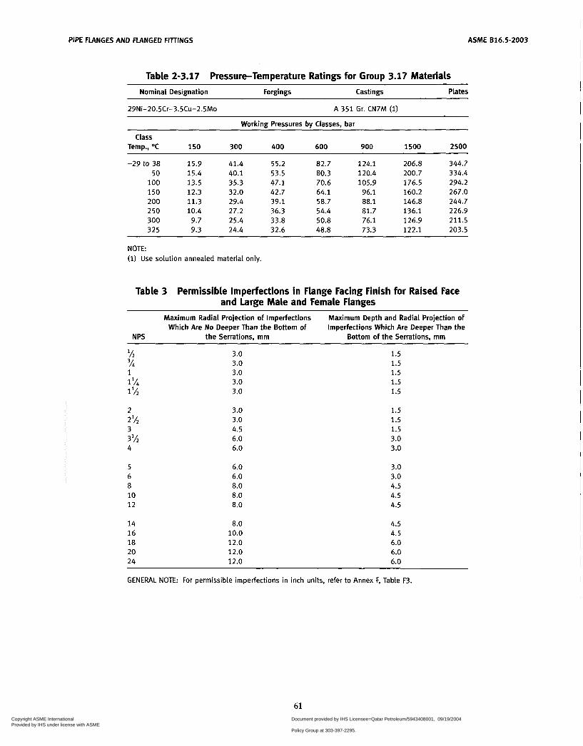
PIPE FLANGES AND FLANGED FIllINGS ASME 816.5-2003
Table 2-3.17 Pressure-Temperature Ratings for Group 3.17 Materials Nominal Designation Forgings Castings Plates
29Ni-20.5Cr-3.5Cu-2.5Mo A 351 Gr. CN7M (1)
Working Pressures by Classes, bar
Temp., O C 150 300 400 600 900 1500 2500
-29 to 38 15.9 41.4 55.2 82.7 124.1 206.8 344.7 50 15.4 40.1 53.5 80.3 120.4 200.7 334.4
1 O0 13.5 35.3 47.1 70.6 105.9 176.5 294.2 150 12.3 32.0 42.7 64.1 96.1 160.2 267.0 200 11.3 29.4 39.1 58.7 88.1 146.8 244.7 250 10.4 27.2 36.3 54.4 81.7 136.1 226.9 300 9.7 25.4 33.8 50.8 76.1 126.9 211.5 325 9.3 24.4 32.6 48.8 73.3 122.1 203.5
Class
NOTE: (1) Use solution annealed material only.
Table 3 Permissible Imperfections in Flange Facing Finish for Raised Face and Large Male and Female Flanges
Maximum Radial Projection of Imperfections Which Are No Deeper Than the Bottom of
Maximum Depth and Radial Projection of Imperfections Which Are Deeper Than the
N PS the Serrations, mm Bottom of the Serrations, mm
lh 3h
1% 1 lh
2%
3%
1
2
3
4
5 6 8 10 12
14 16 18 20 24
3.0 3.0 3.0 3.0 3.0
3.0 3.0 4.5 6.0 6.0
6.0 6.0 8.0 8.0 8.0
8.0 10.0 12.0 12.0 12.0
1.5 1.5 1.5 1.5 1.5
1.5 1.5 1.5 3.0 3.0
3.0 3.0 4.5 4.5 4.5
4.5 4.5 6.0 6.0 6.0
GENERAL NOTE: For permissible imperfections in inch units, refer to Annex F, Table F3.
61 Copyright ASME International Provided by IHS under license with ASME
Document provided by IHS Licensee=Qatar Petroleum/5943408001, 09/19/200422:36:17 MDT Questions or comments about this message: please call the DocumentPolicy Group at 303-397-2295.
--```,,`,``,,,,`,,``````,,``,`-`-`,,`,,`,`,,`---

PIPE FLANGES AND FLANGED FIllINGS ASME 816.5-2003
62
Copyright ASME International Provided by IHS under license with ASME
Document provided by IHS Licensee=Qatar Petroleum/5943408001, 09/19/200422:36:17 MDT Questions or comments about this message: please call the DocumentPolicy Group at 303-397-2295.
--```,,`,``,,,,`,,``````,,``,`-`-`,,`,,`,`,,`---
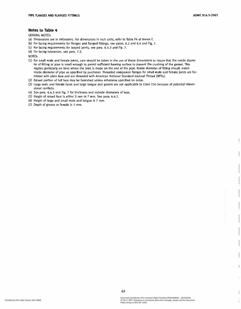
PIPE FLANGES AND FLANGED FITTINGS ASME 816.5-2003
Notes to Table 4 GENERAL NOTES: (a) Dimensions are in milimeters. For dimensions in inch units, refer to Table F4 of Annex F. (b) For facing requirements for flanges and flanged fittings, see paras. 6.3 and 6.4 and Fig. 7. (c) For facing requirements for lapped joints, see para. 6.4.3 and Fig. 7 . (d) For facing tolerances, see para. 7.3. NOTES: (1) For small male and female joints, care should be taken in the use of these dimensions to insure that the inside diame-
ter of fitting or pipe is small enough to permit sufficient bearing surface to prevent the crushing of the gasket. This applies particlarly on lines where the joint is made on the end of the pipe. Inside diameter of fitting should match inside diameter of pipe as specified by purchaser. Threaded companion flanges for small male and female joints are fur- nished with plain face and are threaded with American National Standard Locknut Thread (NPSL).
(2) Raised portion of full face may be furnished unless otherwise specified on order. (3) Large male and female faces and large tongue and groove are not applicable to Class 150 because of potential dimen-
(4) See para. 6.4.3 and Fig. 7 for thickness and outside diameters of laps. (5) Height of raised face is either 2 mm or 7 mm. See para. 6.4.1. (6) Height of large and small male and tongue is 7 mm. (7) Depth of groove or female is 5 mm.
sional conflicts.
63
Copyright ASME International Provided by IHS under license with ASME
Document provided by IHS Licensee=Qatar Petroleum/5943408001, 09/19/200422:36:17 MDT Questions or comments about this message: please call the DocumentPolicy Group at 303-397-2295.
--```,,`,``,,,,`,,``````,,``,`-`-`,,`,,`,`,,`---

ASME 816.5-2003 PIPE FLANGES AND FLANGED FIllINGS
Table 5 Dimensions of Ring Joint Facings (All Pressure Rating Classes)
1 2 3 4 5 6 7 8 9 10 11 12
Nominal Size Groove Dimensions
Radius Class Class Class Class Class Class Class Pitch Depth, at 150 300 400 600 900 1500 2500 Groove Diameter, E Width, Bottom, NPS NPS NPS NPS NPS N PS NPS Number P [Note (i)] i R
. . .
. . .
. . .
. . . 1
. . . 1 ... 1 Ih ...
... 2
. . .
. . . 2%
...
. . .
. . . 3
. . .
. . .
. . . 3 lh ... . . .
4 . . . . . . . . . 5
. . .
. . . 6
. . .
. . .
. . .
. . . 8
. . .
lh
3/i . . .
. . .
. . .
1 . . . 1 . . . 1 lh
. . .
. . . 2 . . . . . .
2% . . . . . . . . . (2)
(2 )
3 l h
. . .
. . .
. . .
. . . 4 . . . . . . . . .
5 . . . . . . . . . 6
. . .
. . .
. . . 8
. . .
. . .
. . .
. . .
. . .
. . .
. . .
. . .
. . .
. . .
. . .
. . .
. . .
. . .
. . .
. . .
. . .
. . .
. . .
. . .
. . .
. . .
. . .
. . .
. . .
. . . 4 . . . . . . . . .
5 . . . . . . . . . 6
. . .
. . .
. . . 8
lh
3/i . . .
...
...
1 ... ... . . . 1
...
. . . 2
. . .
. . .
2% . . . . . . ... (2)
(2)
3%
. . .
...
. . .
. . . 4 . . . . . . . . .
5 . . . . . . . . . 6
. . .
. . .
. . . 8
...
. . .
. . .
. . .
...
. . .
. . .
...
...
. . .
. . .
...
. . .
. . .
. . .
...
. . .
. . .
...
...
3 ... ... ... . . .
... 4 . . . . . . . . .
5 . . . . . . ... 6
. . .
...
...
. . .
. . . lh
3/i ...
. . .
1 . . . 1%
1 % .. .
. . .
. . .
. . . 2
...
. . . 2 lh ... . . . . . .
...
. . .
. . .
. . . 3
. . .
. . .
. . . 4 . . .
...
. . .
. . . 5
...
6 . . . ... . . .
...
... % . . . ...
3/i ... 1
. . .
. . .
1% . . . 1 ... . . .
2 ... 2% . . . . . .
. . . 3
. . .
. . .
. . .
. . .
. . . 4
. . .
...
. . . 5
...
. . .
. . .
. . . 6
. . .
. . .
64
R11 12 13 14 1 5
16 17 18 19 20
21 22 23 24 25
26 27 28 29 30
3 1 32 33 34 3 5
36 37 38 39 40
41 42 43 44 45
46 47 48 49
34.14 39.67 42.88 44.45 47.63
50.80 57.15 60.33 65.07 68.27
72.23 82.55 82.55 95.25
101.60
101.60 107.95 111.13 114.30 117.48
123.83 127.00 131.78 131.78 136.53
149.23 149.23 157.18 161.93 171.45
180.98 190.50 193.68 193.68 211.12
211.14 228.60 247.65 269.88
5.54 6.35 6.35 6.35 6.35
6.35 6.35 6.35 6.35 6.35
7.92 6.35 7.92 7.92 6.35
7.92 7.92 9.52 6.35 7.92
7.92 9.53 6.35 7.92 7.92
6.35 7.92
11.13 7.92 6.35
7.92 12.70 6.35 7.92 7.92
9.53 12.70
6.35 7.92
7.14 8.74 8.74 8.74 8.74
8.74 8.74 8.74 8.74 8.74
11.91 8.74
11.91 11.91
8.74
11.91 11.91 13.49
8.74 11.91
11.91 13.49
8.74 11.91 11.91
8.74 11.91 16.66 11.91
8.74
11.91 19.84 8.74
11.91 11.91
13.49 19.84 8.74
11.91
0.8 0.8 0.8 0.8 0.8
0.8 0.8 0.8 0.8 0.8
0.8 0.8 0.8 0.8 0.8
0.8 0.8 0.8 0.8 0.8
0.8 1.5 0.8 0.8 0.8
0.8 0.8 1.5 0.8 0.8
0.8 1.5 0.8 0.8 0.8
1.5 1.5 0.8 0.8
Copyright ASME International Provided by IHS under license with ASME
Document provided by IHS Licensee=Qatar Petroleum/5943408001, 09/19/200422:36:17 MDT Questions or comments about this message: please call the DocumentPolicy Group at 303-397-2295.
--```,,`,``,,,,`,,``````,,``,`-`-`,,`,,`,`,,`---
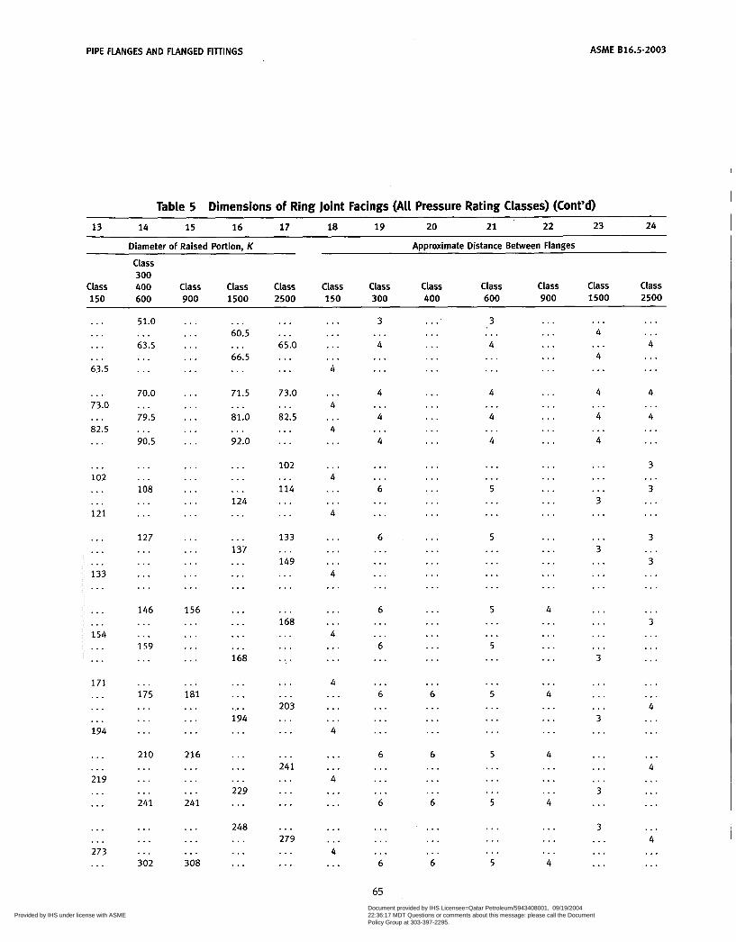
PIPE FLANGES AND FLANGED FIllINGS ASME B16.5-2003
Table 5 Dimensions of Ring Joint Facings (All Pressure Rating Classes) (Cont’d) 13 14 15 16 17 18 19 20 21 22 23 24
Diameter of Raised Portion, K Approximate Distance Between Flanges
Class 300
Class Class Class Class 400 Class Ciass Class Class Class Class class 150 600 900 1500 2500 150 300 400 600 900 1500 2500
...
...
. . .
... 63.5
... 73.0
82.5 ...
...
... 102 ... . . . 121
. . .
...
... 133 ...
...
... 154 ... . . .
171 . . . ... ... 194
. . .
... 219 . . . ...
...
... 273 ...
51.0
63.5 ...
...
. . .
70.0
79.5
90.5
...
. . .
...
... 108 ... ...
127 . . . . . . ... . . .
146 ... .,. 159 ...
. . . 175 ... . . . ...
210 ... ... ... 241
...
...
. . . 302
...
. . .
. . .
. . .
...
. . .
. . .
. . .
. . .
...
. . .
...
...
. . .
. . .
...
. . .
...
...
. . .
156 . . . . . . . . . ...
. . . 181 ... . . . . . .
216 . . . . . . . . . 241
. . .
. . .
. . . 308
. . . 60.5
66.5 ...
. . .
71.5
81.0
92.0
. . .
. . .
. . .
...
.,. 124 . . .
... 137 . . . ... ...
...
. . .
.,.
. ’ . 168
. . .
. . .
... 194 . . .
. . .
. . .
... 229 . . .
248 . . . ... ...
...
. . . 65.0 ... . . .
73.0
82.5 . . .
...
...
102
114 . . . . . . ...
133
149 . . .
...
. . .
... 168 ... ... . . .
...
. . . 203 . . . . . .
. . . 241 . . . . . . . . .
. . . 279 . . . . . .
...
. . .
...
... 4
. . . 4
4 ...
...
... 4 ... ... 4
...
...
. . . 4 ...
...
... 4 ... . . .
4 . . . ... . . . 4
. . .
... 4 . . . ...
. . .
. . . 4
. . .
3
4 ...
...
...
4
4
4
...
...
...
. . . 6 ... ...
6 . . . ... ... ...
6 . . . ... 6 ...
... 6 ... ... . . .
6 . . . ... ... 6
...
. . .
... 6
65
...
. . .
...
...
. . .
...
. . .
...
...
. . .
. . .
. . .
...
. . .
. . .
. . .
...
. . .
...
...
. . .
...
. . .
...
. . .
... 6 . . . . . . . . .
6 . . . . . . ... 6
...
. . .
. . . 6
3
4 . . .
. . .
. . .
4
4
4
. . .
...
...
... 5
. . .
. . .
5 . . . . . . ... . . .
5 . . . ... 5
. . .
. . . 5
. . .
. . .
. . .
5 ... . . . . . . 5
. . .
...
. . . 5
...
... ,.. ... . . .
...
...
...
...
. . .
. . .
...
...
...
...
. . .
...
. . .
...
...
4 ... . . . . . . ...
... 4 . . . ... . . .
4 . . . . . . ... 4
...
. . .
. . . 4
. . . 4
4 ...
. . .
4
4
4
. . .
...
. . .
...
... 3
. . .
. . . 3
. . .
. . .
...
. . .
...
...
. . . 3
. . .
...
. . . 3 . . .
. . .
. . .
... 3
. . .
3 . . . . . . . . .
...
. . . 4 . . . . . .
4
4 ...
...
...
3
3 ...
...
...
3
3 ...
...
...
. . . 3
...
. . .
...
...
... 4 ... ...
. . . 4 ... . . . ...
. . . 4 ... . . .
Copyright ASME International Provided by IHS under license with ASME
Document provided by IHS Licensee=Qatar Petroleum/5943408001, 09/19/200422:36:17 MDT Questions or comments about this message: please call the DocumentPolicy Group at 303-397-2295.
--```,,`,``,,,,`,,``````,,``,`-`-`,,`,,`,`,,`---

ASME 616.5-2003 PIPE FLANGES AND FLANGED FITTINGS
Table 5 Dimensions of Ring Joint Facings (All Pressure Rating Classes) (Cont'd) 1 2 3 4 5 6 7 8 9 10 11 ' 12
Nominal Size Groove Dimensions
Radius Class Class Class Class Class Class Class Pitch at 150 300 400 600 900 1500 2500 Groove Diameter, Depth. Width, Bottom, N PS NPS N PS N PS N PS NPS NPS Number P E F R
...
. . . 10 ... ... ...
12 ... ... 14 ... ... ... ... 16 ... ... ... 18 ... ...
... 20 ... ... ...
24 ... ... ...
. . .
. . .
. . . 10 . . . ...
... 12 ... . . . ... 14 ... . . . ... 16
...
. . .
... 18 ...
...
... 20 . . . . . .
... 24 . . . ...
. . . . . .
. . . . . .
. . . ... 10 10 ... ... . . . . . .
... ... 1 2 12 ... . . . . . . . . . ... .,. 14 14 ... ... ... . . . ... . . . 16 16
... ...
... ...
... ... 18 18 ... . . .
... . . .
. . . . . . . 20 20 ... ... . . . ... . . . . . . 24 2 4. . . . . . . ... ...
. . .
. . .
... 10 . . . . . .
... 12 . . . . . . ...
.,. 14 ... ... ...
16 ... . . . ... 18
. . .
. . .
... 20 . . . . . . ... 24 . . .
8 ... . . . ... 10 . . .
. . .
... 12 . . . ...
,.. ... 14 ... ...
... 16 . . . ... . . . 18 ... ... . . . 20
...
...
... 24
... 8 ... . . . . . . 10
...
. . .
. . .
. . . 12
..,
. . .
...
. . .
...
. . .
...
. . .
. . .
...
. . .
...
. . .
...
...
...
...
. . .
...
50 51 5 2 53 54 5 5
56 57 58 59 60
61 62 63 64 65
66 67 68 69 70
71 72 73 74 75
76 77 78 79
269.88 279.40 304.80 323.85 323.85 342.90
381.00 381.00 381.00 396.88 406.40
419.10 419.10 419.10 454.03 469.90
469.90 469.90 517.53 533.40 533.40
533.40 558.80 584.20 584.20 584.20
673.10 692.15 692.15 692.15
11.13 14.27 6.35 7.92
11.13 17.48
6.35 7.92
14.27 6.35
17.48
7.92 11.13 15.88 6.35 7.92
11.13 17.48
6.35 7.92
12.70
17.48 6.35 9.53
12.70 17.48
6.35 11.13 15.88 20.62
16.66 23.01
8.74 11.91 16.66 30.18
8.74 11.91 23.01
8.74 33.32
11.91 16.66 26.97
8.74 11.91
16.66 30.18
8.74 11.91 19.84
30.18 8.74
13.49 19.84 33.32
8.74 16.66 26.97 36.53
1.5 1.5 0.8 0.8 1.5 2.4
0.8 0.8 1.5 0.8 2.4
0.8 1.5 2.4 0.8 0.8
1.5 2.4 0.8 0.8 1.5
2.4 0.8 1.5 1.5 2.4
0.8 1.5 2.4 2.4
66 Copyright ASME International Provided by IHS under license with ASME
Document provided by IHS Licensee=Qatar Petroleum/5943408001, 09/19/200422:36:17 MDT Questions or comments about this message: please call the DocumentPolicy Group at 303-397-2295.
--```,,`,``,,,,`,,``````,,``,`-`-`,,`,,`,`,,`---

PIPE FLANGES AND FLANGED FIllINGS ASME 816.5-2003
Table 5 Dimensions of Ring Joint Facings (Ail Pressure Rating Classes) (Cont'd) 13 14 15 16 17 18 19 20 21 22 23 24
~ ~
Diameter of Raised Portion, K
Class 300
Approximate Distance Between Flanges
Class 400 Class Class Class Class Class Class Class Class Class Class 150 600 900 1500 2500 150 300 400 600 900 1500 2500
...
... 330 ... ... ...
406 ... . . . 425 ...
...
...
. . . 483 ...
. . .
... 546 . . . ...
. . . 597 ... . . . ...
711 ... ... . . .
...
...
... 356 ... ...
... 413 . . . ... ...
457 ... . . . ... 508
...
...
. . . 575 ...
. . .
... 63 5 . . . ...
... 749 ... ...
. . .
...
... 362 ... ...
... 419 . . . . . . ...
. . . 467 ... . . . ...
524 ... ... . . . 594
. . .
. . .
... 648 . . .
. . .
. . . 772 ...
318 ... ... ... 371 . . .
...
. . . 438 ... . . . ... ... 489 ... ...
... 546 ... ... ...
613 . . . ... ... 673
...
. . .
. . . 794
... 340 ... ... . . . 425
. . .
...
. . .
. . . 495
. . .
. . .
...
. . .
. . .
. . .
. . .
...
...
. . .
...
...
. . .
...
...
...
...
...
. . .
...
... 4 ... ... . . .
4 . . . . . . 3
. . .
...
...
. . . 3 . . .
. . .
. . . 3 ... . . .
. . . 3 ... . . . ... 3
. . .
...
. . .
. . .
...
. . . 6 ... . . .
... 6 ... ... ...
6 ... . . . ... 6
. . .
...
... 6 ...
...
... 6 . . . . . .
. . . 6 ... ...
. . .
. . .
. . . 6 . . . . . .
... 6 . . . . . . . . .
6 . . . . . . ... 6
. . .
. . .
... 6 ...
. . .
... 6 ... . . .
... 6 ... ...
. . .
. . .
... 5
. . .
...
. . . 5
. . .
...
. . .
5 ... . . . ...
5
. . .
...
... 5
. . .
...
. . . 5
. . .
...
... 6 . . . . . .
...
...
... 4 ... ...
... 4 ... . . . ...
... 4 ... ... ...
4 ... ... ...
5
...
...
... 5
...
...
. . . 6 ...
4 ... . . . . ... 4 ...
...
. . . 5
...
. . .
...
... 6 ... ... ... 8 ... . . . ... 8
...
...
. . . 10
...
...
... 11
... 5
...
...
... 6
...
...
...
... 8
...
...
...
...
...
...
...
...
...
...
...
...
...
...
...
...
...
...
... GENERAL NOTES: (a) üimensions are in millimeters. For dimensions in inch units, refer to Annex F, Table F5. (b) For facing requirements for flanges and flanged fitting, see para. 6.4.1 and Fig. 7. (c) For facing requirements for lapped joints, see para. 6.4.3 and Fig. 7. (d) See para. 4.2.7 for marking requirements. (e) Use Class 600 sizes NPS 'h to NPS 3'h for Class 400. (9 Use Class 1500 in sizes NPS 'h to NPS 2% for Class 900. NOTES: (I) Height of raised portion is equal to the depth of groove dimension E, but is not subjected to the tolerances for E. For-
(2) For ring joints with lapped flanges in Classes 300 and 600, ring and groove number R30 is used instead of R31. TOLERANCES: E (depth) +0.4, -0.0 F (width) 10.2 P (pitch diameter) 10.13 R (radius at bottom)
mer full-face contour may be used.
. R 5 2 +O.& -0.0 R 7 2 10.8
23 deg (angle) i 'h deg
67 Copyright ASME International Provided by IHS under license with ASME
Document provided by IHS Licensee=Qatar Petroleum/5943408001, 09/19/200422:36:17 MDT Questions or comments about this message: please call the DocumentPolicy Group at 303-397-2295.
--```,,`,``,,,,`,,``````,,``,`-`-`,,`,,`,`,,`---

ASME 616.5-2003
REDUCING THREADED AND SLIP-ON PIPE FLANGES
PIPE FLANGES AND FLANGED FITTINGS
1 I
LNote (3)
Threaded
Note (3iJ
Blind Flange
Slip-on Welding
Table 6 Reducing Threaded and Slip-On Flanges for Classes 150 Through 2500
1 2 3 4 5 6
Smallest Size Smallest Size Smallest Size of Reducing of Reducing of Reducing
Outlet Outlet Outlet Nominal Requiring Hub Nominal Requiring Hub Nominal Requiring Hub Pipe Size Flanges Pipe Size Flanges Pipe Size Flanges [Note (41 [Note (111 [Note (41 [Note (111 [Note (411 [Note (111
N PS N PS N PS N PS NPS NPS
1 lh 3 l h 1% 12 3 lh 1 l /4 lh 4 1% 14 3 l h 1 % lh 5 1 16 4
2 1 6 2% 18 4 2% 1% 8 3 20 4
3 1 % 10 3lh 24 4
GENERAL NOTE: Dimensions are in millimeters. For dimensions in inches, refer to Annex F, Table F6.
NOTES: (1) The hub dimensions shall be at least as large as those of the standard flanges of the size to which the reduction is
being machined, except flanges reducing to a size smaller than those of Columns 2, 4, and 6 may be made from blind flanges. See Example.
(2) Class 150 flanges do not have a counterbore. Class 300 and higher pressure flanges will have depth of counterbore Q of 7 mm for NPS 2 and smaller tapping and 9.50 mm for NPS 2% and larger. The diameter Q of counterbore is the same as that given in the tables of threaded flanges for the corresponding tapping.
(3) Minimum length of effective threads shall be at least equal dimension Tof the corresponding pressure class threaded flange as shown in tables but does not necessarily extend for the face of the flange. For thread of threaded flanges, see para. 6.9.
(4) For method of designating reducing threaded and reducing slip-on flanges, see para. 3.3 and Examples below.
EXAMPLES: A. The size designation is NPS 6 x 2% - Class 300 reducing threaded flange. This flange has the following dimensions:
NPS 2% = taper pipe thread tapping (ASME B1.20.1) 320 mm = diameter of regular NPS 6 Class 300 threaded flange
35 mm =thickness of regular NPS 6 Class 300 threaded flange 178 mm = diameter of hub for regular NPS 5 Class 300 threaded flange. Hub diameter may be one size small to
15.5 mm = height of hub for regular NPS 5 Class 300 threaded flange. reduce machining. In this example a hub diameter of NPS 2% would be the smallest acceptable.
û. The size designation is NPS 6 X 2 - Class 300 reducing threaded flange. Use regular NPS 6 Class 300 blind flange tapped with NPS 2 taper pipe thread (ASME B1.20.1).
68 Copyright ASME International Provided by IHS under license with ASME
Document provided by IHS Licensee=Qatar Petroleum/5943408001, 09/19/200422:36:17 MDT Questions or comments about this message: please call the DocumentPolicy Group at 303-397-2295.
--```,,`,``,,,,`,,``````,,``,`-`-`,,`,,`,`,,`---

PIPE FLANGES AND FLANGED FIlTINGS ASME 816.5-2003
CLASS 150 PIPE FLANGES AND FLANGED FITTINGS
Flange
Machine Bol t With Nuts
Point height [Note ( I ) ]
Stud Bolt Wi th Nuts
Table 7 Templates for Drilling Class 150 Flanges 1 2 3 4 5 6 7 8 9
Length of Bolts, L
[Notes (11, (411 Drilling [Notes (21, (311 Stud Bolts Machine [Note (111 Bolts
Outside Nominal Diameter Diameter Diameter
Pipe of of Bolt of Bolt Number Diameter 2 mm 2 mm Size, Flange, Circle, Holes, of of Bolts, Raised Ring Raised NPS O W in. Bolts in. Face joint Face
~~ ~
lA 90 60.3 % 4 55 . .. 50 % 1 O0 69.9 % 4 'h 65 ... 50
1 110 79.4 'h 4 IA 65 75 55 1 115 88.9 % 4 Ih 70 85 5 5 1 lA 125 98.4 'h 4 'h 70 85 65
2 150 120.7 3/i 4 '43 85 95 70 2% 180 139.7 3/i 4 % 90 100 75
3 190 152.4 3/i 4 'h 90 100 75 3 lh 215 177.8 3/i 8 'h 90 1 O0 75
4 230 190.5 3/4 8 'h 90 100 75
5 255 215.9 'h 8 3/4 95 110 85 6 280 241.3 % 8 3L 1 O0 1 1 5 85 8 345 298.5 'h 8 3/4 110 120 90
10 405 362.0 1 12 'h 115 1 2 5 1 O0 12 485 431.8 1 12 7/8 120 135 100
14 535 476.3 1 '/8 12 1 135 145 115 16 595 539.8 1 'A3 16 1 135 145 115 18 635 577.9 1% 16 1% 145 160 125 20 700 635.0 1% 20 158 160 170 140 24 81 5 749.3 1 3h 20 1% 170 185 150
GENERAL NOTES: (a) Dimensions of Table 7 are in millimeters, except for diameters of bolts and bolt holes, which are in inch units. For
(b) For other dimensions, see Tables 8 and 9. NOTES: (I) Length of stud bolt does not include the height of the points. See para. 6.10.2. (2) For flange bolt holes, see para. 6.5. (3) For spot facing, see para. 6.6. (4) Bolt lengths not shown in table may be determined in accordance with Annex D. See para. 6.10.2.
dimensions in inch units, refer to Annex F, Table F7.
69
Copyright ASME International Provided by IHS under license with ASME
Document provided by IHS Licensee=Qatar Petroleum/5943408001, 09/19/200422:36:17 MDT Questions or comments about this message: please call the DocumentPolicy Group at 303-397-2295.
--```,,`,``,,,,`,,``````,,``,`-`-`,,`,,`,`,,`---

~
ASME 616.5-2003
-I Y X i N o t e ( I ) ]
Threaded
I- f c o b r 3 4 ‘i Socket Welding (NPS to 3 Only)
Blind
PIPE FLANGES AND FLANGED FITTINGS
-0- Lapped
Welding Neck
Table 8 Dimensions of Class 150 Flanges
70
Copyright ASME International Provided by IHS under license with ASME
Document provided by IHS Licensee=Qatar Petroleum/5943408001, 09/19/200422:36:17 MDT Questions or comments about this message: please call the DocumentPolicy Group at 303-397-2295.
--```,,`,``,,,,`,,``````,,``,`-`-`,,`,,`,`,,`---
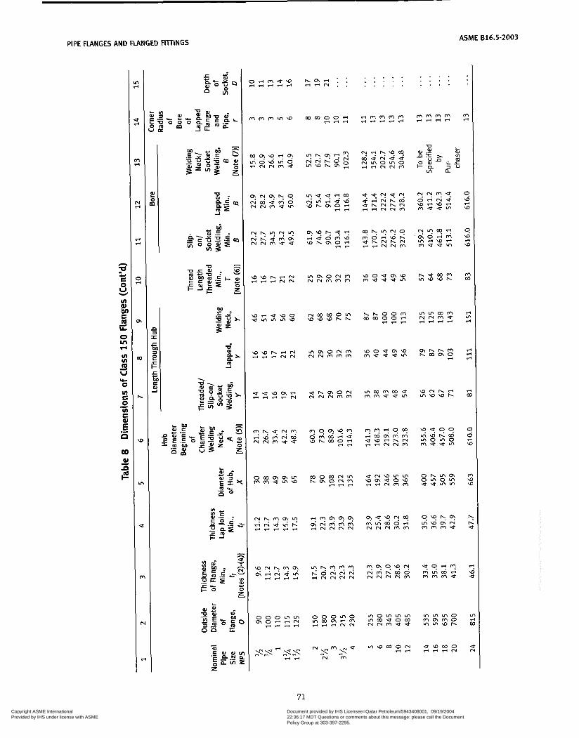
PIPE FLANGES AND FLANGED FlllINGS
z ri W
9 W ri W
m W
T-
T- U
.r F .r
T- U
C C U
0 u U
h h U
? W e
rn ri 00
.;t N
ASME 816.5-2003
L
E! na a l s
E' o
s r r u w o urnrnrnw
o o o m m r n m m u r n w
h a - : : r i r ( N . .
. . . . . . . . . . . . . . .
w o u m w m e u u m
r n o r n r n r n rnoouocn N N ~ U U
r n w r n o ~ .-Id
. . . . . . . . . . . . . . .
m e w - m u u r n
h e w m r n W W h
w u 0 0
m r n r n o m m m o rnrnw-
u w o o o * r i + N
71 Copyright ASME International Provided by IHS under license with ASME
Document provided by IHS Licensee=Qatar Petroleum/5943408001, 09/19/200422:36:17 MDT Questions or comments about this message: please call the DocumentPolicy Group at 303-397-2295.
--```,,`,``,,,,`,,``````,,``,`-`-`,,`,,`,`,,`---
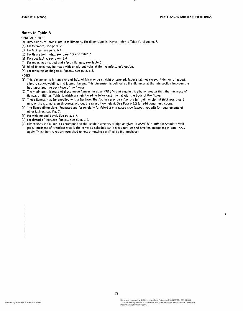
ASME 816.5-2003 PIPE FLANGES AND FLANGED FIllINGS
Notes to Table 8 GENERAL NOTES: (a) Dimensions of Table 8 are in millimeters. For dimensions in inches, refer to Table F8 of Annex F. (b) For tolerance, see para. 7. (c) For facings, see para. 6.4. (d) For flange bolt holes, see para 6.5 and Table 7. (e) For spot facing, see para. 6.6. (9 For reducing threaded and slip-on flanges, see Table 6. (g) Blind flanges may be made with or without hubs at the manufacturer’s option. (h) For reducing welding neck flanges, see para. 6.8. NOTES: (i) This dimension is for large end of hub, which may be straight or tapered. Taper shall not exceed 7 deg on threaded,
slip-on, socket-welding, and lapped flanges. This dimension is defined as the diameter at the intersection between the hub taper and the back face of the flange.
flanges on fittings, Table 9, which are reinforced by being cast integral with the body of the fitting.
mm, or the tf dimension thickness without the raised face height. See Para 6.3.2 for additional restrictions.
other facings, see Fig. 7.
(2) The minimum thickness of these loose flanges, in sizes NPS 3’h and smaller, is slightly greater than the thickness of
(3) These flanges may be supplied with a flat face. The flat face may be either the full tfdimension of thickness plus 2
(4) The flange dimensions illustrated are for regularly furnished 2 mm raised face (except lapped); for requirements of
(5 ) For welding end bevel. See para. 6.7. (6) For thread of threaded flanges, see para. 6.9. (7) Dimensions in Column 13 correspond to the inside diameters of pipe as given in ASME B36.10M for Standard Wall
pipe. Thickness of Standard Wall is the same as Schedule 40 in sizes NPS 10 and smaller. Tolerances in para. 7.5.2 apply. These bore sizes are furnished unless otherwise specified by the purchaser.
72
Copyright ASME International Provided by IHS under license with ASME
Document provided by IHS Licensee=Qatar Petroleum/5943408001, 09/19/200422:36:17 MDT Questions or comments about this message: please call the DocumentPolicy Group at 303-397-2295.
--```,,`,``,,,,`,,``````,,``,`-`-`,,`,,`,`,,`---
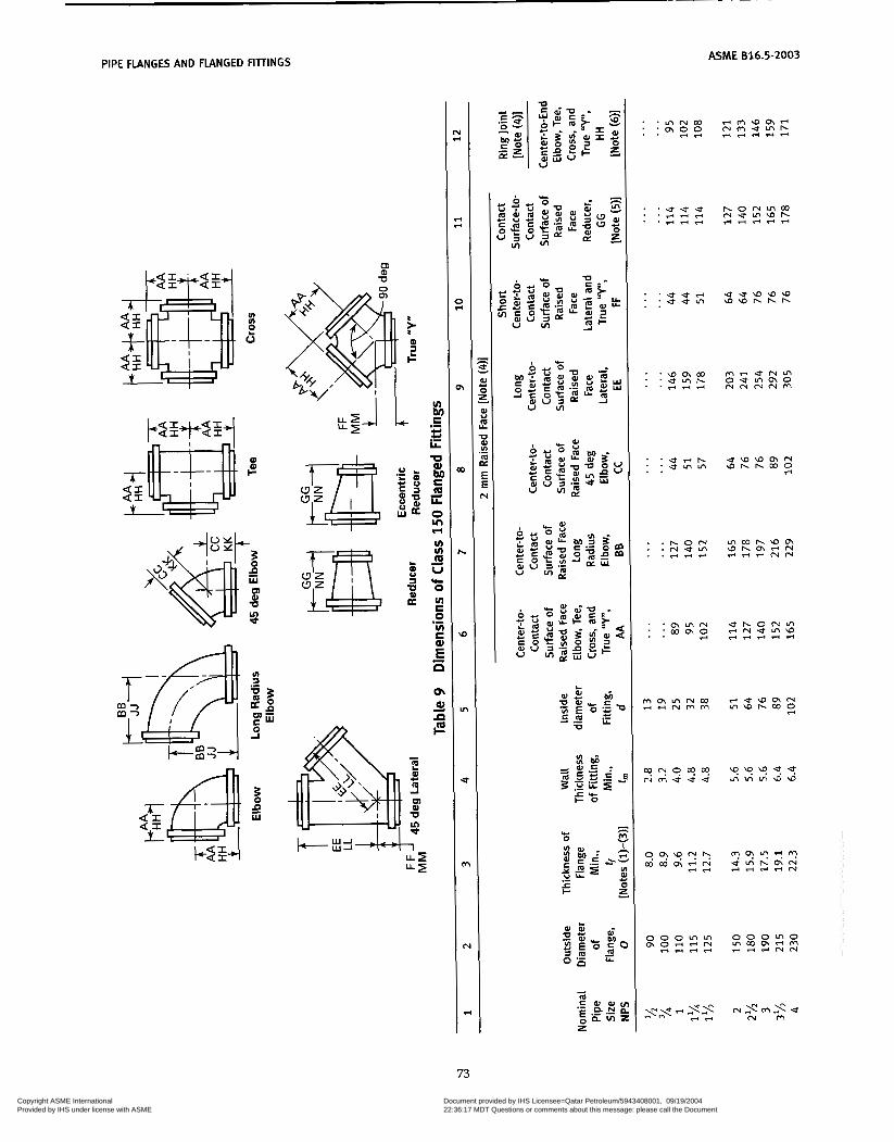
~
PIPE FLANGES AND FLANGED FITnNGS ASME 016.5-2003
' U U + ' * u m
85 Tu t
U C C U C
.-
.- E C
U
z a
F -
' m m N ' w m o
rr
73
Copyright ASME International Provided by IHS under license with ASME
Document provided by IHS Licensee=Qatar Petroleum/5943408001, 09/19/200422:36:17 MDT Questions or comments about this message: please call the DocumentPolicy Group at 303-397-2295.
--```,,`,``,,,,`,,``````,,``,`-`-`,,`,,`,`,,`---

ASME 816.5-2003 PIPE FLANGES AND FLANGED FIìlINGS
P
c 'F c 4 c
Q c s
c
LL
.- c c .-
m iL
iII VI VI m U
O * VI S O VI S .- E E oi ai ã F
r n o r n L n m rnlnlnorn r n m u o m m a m o r i N N ~ V U m m \ ~ h m
74
Copyright ASME International Provided by IHS under license with ASME
Document provided by IHS Licensee=Qatar Petroleum/5943408001, 09/19/200422:36:17 MDT Questions or comments about this message: please call the DocumentPolicy Group at 303-397-2295.
--```,,`,``,,,,`,,``````,,``,`-`-`,,`,,`,`,,`---

-~ ~~ -
ASME 816.5-2003 PIPE FLANGES AND FLANGED FITTINGS
o) u> m m L m a U v)
c - O m d
8 m
a
m
U C
O K
Q
c"
r)
m N
ñ * W O z
N - N M c =
v
e
- .- b W In
m r) N
. . . . . . . . . . 0 \ 0 \ ? ? ' 9 . . . . . m w w w o w w r n m m
. . . . . m m u u w : : : : : - * r ) r ) r )
. . . . . hhhhC-4 . . . . . . ? l + N N m . . . . . F I - - * -
. . . . . r n u u m o . . . . . o r i ~ m u . . . . . - - r ) * r )
. . . . . . . . . . . . . . . . . . . . . . . . . . . . . .
. . ' r n r n r n . .
o m m r n w h m m m o
r)
75
Copyright ASME International Provided by IHS under license with ASME
Document provided by IHS Licensee=Qatar Petroleum/5943408001, 09/19/200422:36:17 MDT Questions or comments about this message: please call the DocumentPolicy Group at 303-397-2295.
--```,,`,``,,,,`,,``````,,``,`-`-`,,`,,`,`,,`---
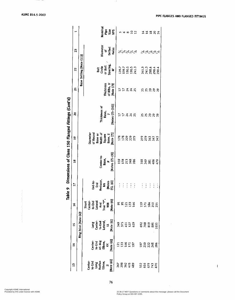
~~~ ~
ASME B16.5-2003 PIPE FLANGES AND FLANGED FITTINGS
P
c F
2 E
S C
e
LL
-e a
m LL
O in r(
VI VI m U
O UI C O UI E
.- c c .-
e
ic
.-
.- E O
u+ oi a d
im
m m r i w o t - U C Q O h M M ~ U U
. . . . . . . . . . . . . . . . . . . . . . . . . . . . . .
I
76
Copyright ASME International Provided by IHS under license with ASME
Document provided by IHS Licensee=Qatar Petroleum/5943408001, 09/19/200422:36:17 MDT Questions or comments about this message: please call the DocumentPolicy Group at 303-397-2295.
--```,,`,``,,,,`,,``````,,``,`-`-`,,`,,`,`,,`---

PIPE FLANGES AND FLANGED FIllINGS ASME 816.5-2003
Notes to Table 9 GENERAL NOTES: (a) Dimensions of Table 9 are in millimeters. For dimensions in inch units, refer to Annex F, Table F9. (b) For tolerances, see para. 7. (c) For facings, see para. 6.4. (d) for flange bolt holes, see para. 6.5 and Table 8. (e) For spot facing, see para. 6.6. (9 For intersecting centerlines, center-to-contact surface, and center-to-end dimensions of side outlet fittings, see para.
6.2.4. (g) For center-to-contact surface and center-to-end dimensions OF special degree elbows, see para. 6.2.5. (h) For reinforcement of certain fittings, see para. 6.1. (i) For drains, see para. 6.12. NOTES: (1) The thickness of flange minimum dimensions for loose flanges, Table 9 sizes NPS 3% and smaller, are slightly heavier
(2) These fittings may be supplied with a flat Face flange. The flat face may be either the full tf, dimension thickness plus 2
(3) The thickness of flange dimension illustrated is for regularly furnished 2 mm raised face (except lapped); for thickness
(4) For center-to-contact surface and center-to-end dimensioins of reducing fittings, see para. 6.2.3. (5) For contact surface-to-contact surface and end-to-end dimensions of reducers and eccentric reducers, see para. 6.2.3. (6) These dimensions apply to straight sizes only. See paras. 6.2.3 and 6.4.2.2. For center-to-end dimensions of reducing
fittings or end-to-end dimensions of reducers, use center-to-contact surface or contact surface-to-contact surface dimensions of 2 mm raised face (flange edge) for largest opening and add the proper height to provide for ring joint groove applying to each flange. See Table 5 for ring joint facing dimensions.
than for flanges on these fittings, which are reinforced by being cast integral with the body of fitting.
mm or the tf dimension thickness without the raised face height. See para. 6.3.2 for additional restrictions.
requirements of other facings, see Fig. 7.
(7) The base dimensions apply to all straight and reducing sizes. (8) For reducing fittings, the size and center-to-face dimension of base are determined by the size of the largest opening of
fittings. In the case of reducing base elbows, orders shall specify whether the base shall be opposite the larger or smaller opening.
dimension. (9) Bases shall be plain faced unless otherwise specified, and the center-to-base dimension R shall be the finished
(10) Bases may be cast integral or attached as weldments at the option of the manufacturer. (Il) The bases of these fittings are intended for support in compression and are not to be used for anchors or supports in
tension or shear.
77
Copyright ASME International Provided by IHS under license with ASME
Document provided by IHS Licensee=Qatar Petroleum/5943408001, 09/19/200422:36:17 MDT Questions or comments about this message: please call the DocumentPolicy Group at 303-397-2295.
--```,,`,``,,,,`,,``````,,``,`-`-`,,`,,`,`,,`---

ASME 816.5-2003 PIPE FLANGES AND FLANGED FITTINGS
CLASS 300 PIPE FLANGES, AND FLANGED FIlTINGS
FL-1
Flange
Machine Bolt With Nut
Point height [Note (111 Stud Bolt With Nuts
Table 10 Templates for Drilling Class 300 Flanges ~~~
1 2 3 4 5 6 7 8 9
Length of Bolts, 1
[Notes (11, (411 Drilling [Notes (2), (3)]
Stud Bolts Machine Outside [Note (111 Bolts Nominal Diameter Diameter Diameter
Pipe of of Bolt of Bolt Number Diameter 2 mm 2 mm Size, Flange, Circle, Holes, of of Bolts, Raised Ring Raised NPS O W in. Bolts in. Face Joint Face
=h 95 66.7 '/i 4 7 2 65 75 5 5 3h 115 82.6 %J 4 % 75 90 65
1 125 88.9 5/, 4 'A3 75 90 65 1 ILA 135 98.4 3LA 4 '/i 85 95 70 1 % 1 5 5 114.3 %3 4 3h 90 100 75
2 165 127.0 3A 8 '8 90 100 75 2% 190 149.2 58 8 3A 100 115 85
3Ih 230 184.2 'A3 8 3h 110 1 2 5 95 4 255 200.0 58 8 3LA 115 125 95
5 280 235.0 '/* 8 3/4 120 135 110 6 320 269.9 %3 12 3LA 120 140 110 8 380 330.2 1 1 2 '/i 140 150 120
3 210 168.3 58 8 3/& 110 120 90
10 445 387.4 11A3 16 1 160 170 140 12 520 450.8 1 % 16 1% 170 185 145
14 585 514.4 1% 20 1 'A3 180 190 160 16 650 571.5 1 3,4 20 1% 190 205 165 18 710 628.6 1 ' ~ 3 24 1% 195 210 170 20 775 685.8 1 5/, 24 1 lLA 205 220 185 24 91 5 812.8 1 24 1% 2 30 255 205
GENERAL NOTES: (a) Dimensions of Table 10 are in millimeters, except for diameters of bolts and bolt holes, which are in inch units. For
(b) For other dimensions, see Tables 11 and 12.
NOTES: (i) Length of stud bolt does not include the height of the points. See para. 6.10.2. (2) For flange bolt holes, see para. 6.5. (3) For spot facing, see para 6.6. (4) Bolt lengths not shown in table may be determined in accordance with Annex D. See para. 6.10.2.
dimensions in inch units, refer to Annex F. Table FIO.
78
Copyright ASME International Provided by IHS under license with ASME
Document provided by IHS Licensee=Qatar Petroleum/5943408001, 09/19/200422:36:17 MDT Questions or comments about this message: please call the DocumentPolicy Group at 303-397-2295.
--```,,`,``,,,,`,,``````,,``,`-`-`,,`,,`,`,,`---
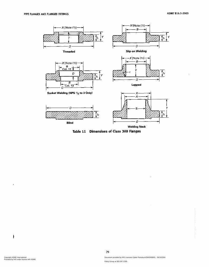
PIPE FLANGES AND FLANGED FIllINGS ASME 816.5-2003
-0- Threaded
Socket Welding (NPS to 3 Only)
Blind
Slip-on Welding
h X i N Y
-0- Welding Neck
Table 11 Dimensions of Class 300 Flanges
79 Copyright ASME International Provided by IHS under license with ASME
Document provided by IHS Licensee=Qatar Petroleum/5943408001, 09/19/200422:36:17 MDT Questions or comments about this message: please call the DocumentPolicy Group at 303-397-2295.
--```,,`,``,,,,`,,``````,,``,`-`-`,,`,,`,`,,`---
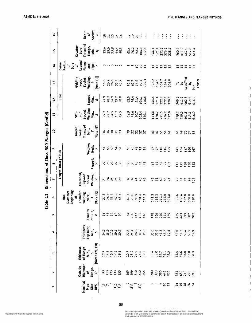
ASME 616.5-2003 PIPE FLANGES AND FLANGED FITTINGS
o r i m u w r i r i - 4 -
. . . . . . . . . . . . . . . . . . . .
m m m i n w cocooori ririri
rnWhCnZ
U a l - 5 s m
u e m u m N N m U O
C O h r n N O
w w c o - m ririri" e m o e m
W W h h W
- w o u h mrnw\Dw c o r n c o m e Whhhco
m m m e m m m e u e
C n r i O r n " J r n W W h
u o h m w c o o e m u - + r i r i
m o o o m w m e m r n r i r i N N N
o o o r n o CONcoeN m m m u m
80 Copyright ASME International Provided by IHS under license with ASME
Document provided by IHS Licensee=Qatar Petroleum/5943408001, 09/19/200422:36:17 MDT Questions or comments about this message: please call the DocumentPolicy Group at 303-397-2295.
--```,,`,``,,,,`,,``````,,``,`-`-`,,`,,`,`,,`---

PIPE FLANGES AND FLANGED FIlTINGS ASME 616.5-2003
Notes to Table 11 GENERAL NOTES: (a) Dimensions of Table 11 are in millimeters. For dimensions in inch units, refer to Annex F Table, F11. (b) For tolerances, see para i. (CI For facings, see para. 6.4. (dl For flange bolt holes, see para. 6.5 and Table 10 (e) For spot facing, see para. 6.6. (0 For reducing threaded and slip-on flanges, see Table 6. (g) Blind flanges may be made with or without hubs at the manufacturer's option. (h) For reducing welding neck flanges, see para. 6.8. NOTES: (1) This dimension is For large end of hub, which may be straight or tapered. Taper shall not exceed 7 deg on threaded,
slip-on, socket-welding, and lapped flanges. This dimension is defined as the diameter at the intersection between the hub taper and the back face of the flange.
or the tf dimension thickness without the raised face height. See para. 6.3.2 for additional restrictions.
other facings, see Fig. 7.
(2) These flanges may be supplied with a flat face. The flat face may be either the full tf dimension thickness plus 2 mm
(3) The flange dimensions illustrated are for regularly furnished 2 mm raised face (except lapped); for requirements of
(4) For welding end bevel, see para. 6.7. (5) For thread of threaded flanges, see para. 6.9. (6) Dimensions in Column 13 correspond to the inside diameters of pipe as given in ACME B36.10M for Standard Wall
pipe. Standard Wall dimensions are the same as Schedule 40 in sizes N P S 10 and smaller. Tolerances in para. 7.5.2 apply. These bore sizes are furnished unless otherwise specified by the purchaser.
81
Copyright ASME International Provided by IHS under license with ASME
Document provided by IHS Licensee=Qatar Petroleum/5943408001, 09/19/200422:36:17 MDT Questions or comments about this message: please call the DocumentPolicy Group at 303-397-2295.
--```,,`,``,,,,`,,``````,,``,`-`-`,,`,,`,`,,`---
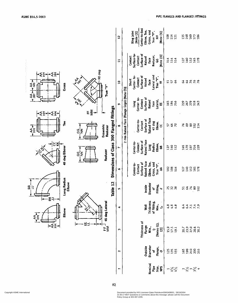
ASME 816.5-2003 PIPE FLANGES A N D FLANGED FITTINGS
o> al U
82
Copyright ASME International Provided by IHS under license with ASME
Document provided by IHS Licensee=Qatar Petroleum/5943408001, 09/19/200422:36:17 MDT Questions or comments about this message: please call the DocumentPolicy Group at 303-397-2295.
--```,,`,``,,,,`,,``````,,``,`-`-`,,`,,`,`,,`---

PIPE FLANGES AND FLANGED FIllINGS ASME B16.5-2003
ri CI
CI CI
O CI
o,
a)
I-
u)
In
.;f
m
N
CI
n
C O
P
s G
U
C .- U U
Y
u Q, et E o Y
O O m u) u) o u O VI E O VI E
.-
L
d
*
.-
.- ì! n F( ri Q, z i-
\ D r i U h r n + u m \ o o N N N N M
h h N M U r n m m m m m m e u m
u w m o u M e - "
83 Copyright ASME International Provided by IHS under license with ASME
Document provided by IHS Licensee=Qatar Petroleum/5943408001, 09/19/200422:36:17 MDT Questions or comments about this message: please call the DocumentPolicy Group at 303-397-2295.
--```,,`,``,,,,`,,``````,,``,`-`-`,,`,,`,`,,`---

ASME 816.5-2003 PIPE FLANGES AND FLANGED FITTINGS
In al O c - c. - O m
al v)
m"
E 'o C
ri *T*T nr i
. . . . . . " U ' ? ' ? ? "9?0! . . . m c o u u h a m o o m m m - r i r i u u o o w r i r ie r i r i m r i m
. . . . . . m m w w w m m m r i r n . . . * r i r i e r i r i r I N N N
. . . . . . . . . m m w w l n m m m l n w * - r i e r i
o o u u c o m m m m r i n r i m m m
. . . . . . . . . . . . . . . . . . . . . . . . . . . . . . . . . . . . . . .
h e 0 m w h horncoo m r i m u w riririri
84 Copyright ASME International Provided by IHS under license with ASME
Document provided by IHS Licensee=Qatar Petroleum/5943408001, 09/19/200422:36:17 MDT Questions or comments about this message: please call the DocumentPolicy Group at 303-397-2295.
--```,,`,``,,,,`,,``````,,``,`-`-`,,`,,`,`,,`---
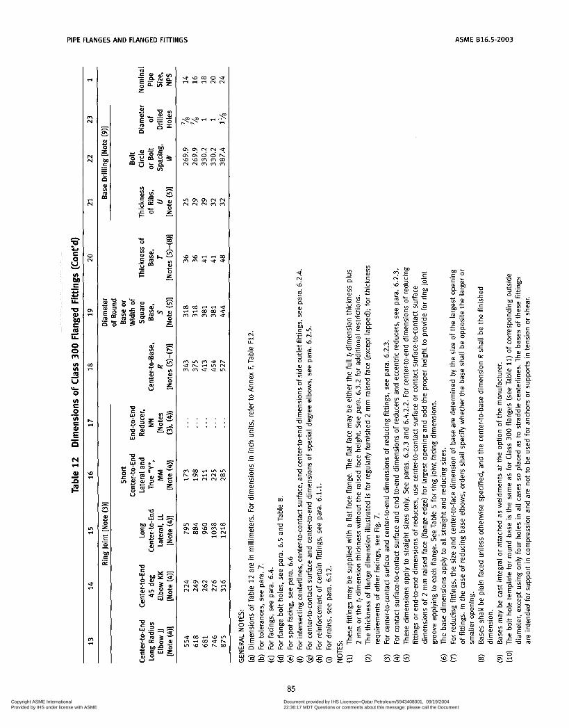
PIPE FLANGES AND FLANGED FITTINGS
n
S O
u)
E
P
2 U
bi: .- U U .- LL
U al bl S m LL
O O m u) u) <p U
O u) æ O u) c
d
4
b
.-
.- E n
hl FI
aJ z F
r4
m N
N N
%-I N
N
o\ s-4
01 s-4
h %-I
\o %-I
ln 7 4
U %-I
m r4
W O Y
f. .- E - - .- L
n
m W VI m
ñ m & O
- h
v m W O z E O
Y
I
c) .- - .- E ai
W
e w m o u e s - 4 r i N N
V \ O \ Q \ N N N N N M M
w w r i s - 4 m M M e U U
. . . . . . . . . . . . . . .
U c n N u J U l N u W h + N N N N M
& ri U
al -a
U-
x al S
- P
4 O c L
2
ui o) L
c .- S 3
c U S
c
VI S O
v) S
.-
.-
.-
.- E
g .- E
-0
O U L
Y
- - .- E S .-
ASME B16.5-2003
85 Copyright ASME International Provided by IHS under license with ASME
Document provided by IHS Licensee=Qatar Petroleum/5943408001, 09/19/200422:36:17 MDT Questions or comments about this message: please call the DocumentPolicy Group at 303-397-2295.
--```,,`,``,,,,`,,``````,,``,`-`-`,,`,,`,`,,`---

~~~ ~ ~~
ASME 816.5-2003 PIPE FLANGES AND FLANGED FITTINGS
CLASS 400 PIPE FLANGES
-0-
Point height [Note i l ) ]
Flange Stud Bolt With Nuts
Table 13 Templates for Drilling Class 400 Flanges 1 2 3 4 5 6 7 8 9
Length of Bolts, 1
[Notes (11, (411 Drilling [Notes (2). (311
Outside Diameter Diameter Male and Nominal Diameter of Bolt of Bolt Number Diameter 7 mm Female/
Pipe of Flange, Circle, Holes of of Bolts Raised Tongue Ring Size NPS O W in. Bolts in. Face and Groove Joint
Use Class 600 Dimensions in these sizes
2
3 2%
3 lA 4 255 200.0 1 8 % 140 135 140 5 280 235.0 1 8 58 145 135 145 6 320 269.9 1 12 5 / , 150 145 150 8 380 330.0 1 'h 12 1 170 165 170 10 445 387.4 1% 16 1'h 190 185 190 12 5 20 450.8 1 3h 16 1 205 195 205
14 585 514.4 1 'h 20 1% 210 205 210 16 650 571.5 1 Ih 20 1 58 220 215 220
24 91 5 812.8 1 24 1 3~ 265 260 280
18 710 628.6 1% 24 1 230 220 230 20 775 685.8 1% 24 1% 240 235 250
GENERAL NOTES: (a) Dimensions of Table 13 are in milimeters, except for diameter of bolts and bolt holes, which are in inch units. For
dimensions in inch units refer to Annex F, Table F13. (b) For other dimensions, see Table 14. NOTES: (1) Length of stud bolt does not include the height of the points. See para. 6.10.2. (2) For flange bolt holes, see para. 6.5. (3) For spot facing, see para. 6.6. (4) Bolt lengths not shown in table may be determined in accordance with Annex D. See, para. 6.10.2.
86 Copyright ASME International Provided by IHS under license with ASME
Document provided by IHS Licensee=Qatar Petroleum/5943408001, 09/19/200422:36:17 MDT Questions or comments about this message: please call the DocumentPolicy Group at 303-397-2295.
--```,,`,``,,,,`,,``````,,``,`-`-`,,`,,`,`,,`---
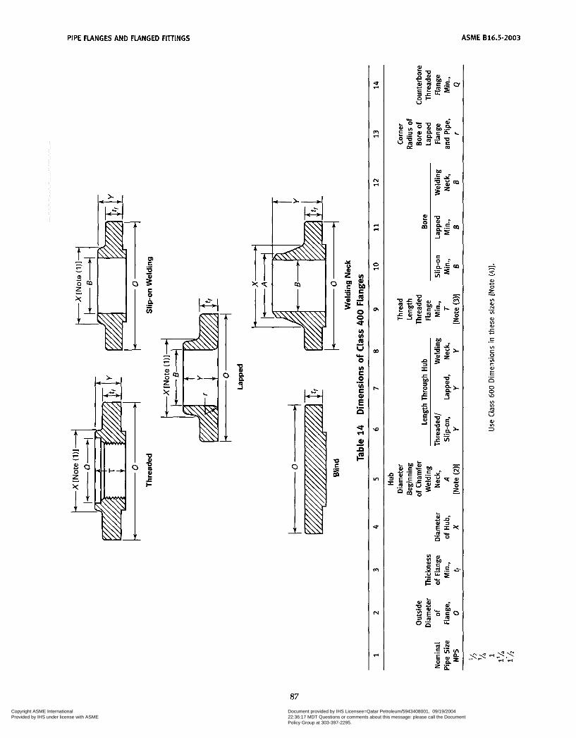
PIPE FLANGES AND FLANGED FIllINGS
~~
ASME 816.5-2003
VI VI m U * O VI C O VI C
L
.-
.- E n
2
I=
a d
n
- h
s. W O z VI W N
VI
W VI W
w
u
.-
5 C
VI C O
VI c
.-
.-
.- E n O O \o
VI VI m U
W VI 3
-
87 Copyright ASME International Provided by IHS under license with ASME
Document provided by IHS Licensee=Qatar Petroleum/5943408001, 09/19/200422:36:17 MDT Questions or comments about this message: please call the DocumentPolicy Group at 303-397-2295.
--```,,`,``,,,,`,,``````,,``,`-`-`,,`,,`,`,,`---
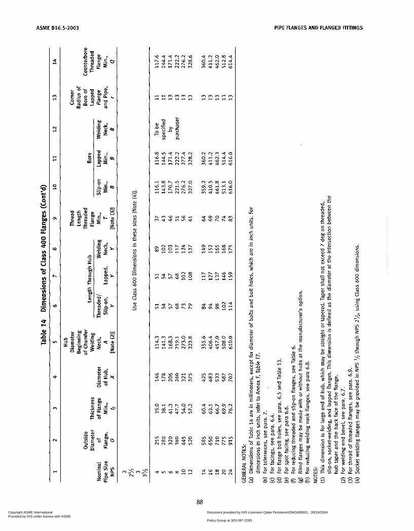
ASME 816.5-2003 PIPE FLANGES AND FLANGED FITTINGS
n
E O
P
t! U
O O U
b O VI æ O VI æ al
P
.- E .-
al ñ ii
al
O t U
c - 1:' g i
- 3
-c U c .-
88 Copyright ASME International Provided by IHS under license with ASME
Document provided by IHS Licensee=Qatar Petroleum/5943408001, 09/19/200422:36:17 MDT Questions or comments about this message: please call the DocumentPolicy Group at 303-397-2295.
--```,,`,``,,,,`,,``````,,``,`-`-`,,`,,`,`,,`---

PIPE FLANGES AND FLANGED FIlTINGS ASME 816.5-2003
CLASS 600 PIPE FLANGES AND FLANGED FITTINGS
Point height [Note (111
Flange Stud Bolt With Nuts
Table 1 5 Templates for Drilling Class 600 Flanges 1 2 3 4 5 6 7 8 9
Length of Bolts, 1
[Notes (i), (41 Drilling [Notes (2), (3)] Outside Diameter Diameter Male and
Nominal Diameter of Bolt of Bolt Number Diameter 7 mm Femalel Pipe Size of Flange, Circle, Holes of of Bolts Raised Tongue Ring
N PS O W in. Bolts in. Face and Groove Joint
95 115 125 135 155
66.7 82.6 88.9 98.4 114.3
4. 4 4 4 4
75 90 90 95 110
70 85 85 90 100
75 90 90 95 110
1 1 lh 1%
2
3
4
2%
3%
165 190 210 230 275
127.0 149.2 168.3 184.2 215.9
110 120 125 140 145
100 115 120 135 140
110 120 125 140 145
5 6 8 10 12
330 355 420 510 5 60
266.7 292.1 349.2 431.8 489.0
8 12 12 16 20
165 170 190 215 220
160 165 185 210 215
165 170 195 215 220
14 16 18 20 24
605 685 745 81 5 940
527.0 603.2 654.0 723.9 838.2
20 20 20 24 24
235 255 275 285 330
230 250 265 280 325
235 255 275 290 335
GENERAL NOTES: (a) Dimensions of Table 15 are in millimeters, except for diameters of bolts and bolt holes, which are expressed in
units. For dimensions in inch units, refer to Annex F, Table F15. (b) For other dimensions, see Table 16. NOTES: (1) Length of stud bolt does not include the height of the points. See para 6.10.2. (2) For flange bolt holes, see para. 6.5. (3) For spot facing, see para 6.6. (4) Bolt lengths not shown in table may be in accordance with Annex D. See para. 6.10.2.
inch
89 Copyright ASME International Provided by IHS under license with ASME
Document provided by IHS Licensee=Qatar Petroleum/5943408001, 09/19/200422:36:17 MDT Questions or comments about this message: please call the DocumentPolicy Group at 303-397-2295.
--```,,`,``,,,,`,,``````,,``,`-`-`,,`,,`,`,,`---

ASME 616.5-2003 PIPE FLANGES AND RANGED FIilINGS
90 Copyright ASME International Provided by IHS under license with ASME
Document provided by IHS Licensee=Qatar Petroleum/5943408001, 09/19/200422:36:17 MDT Questions or comments about this message: please call the DocumentPolicy Group at 303-397-2295.
--```,,`,``,,,,`,,``````,,``,`-`-`,,`,,`,`,,`---
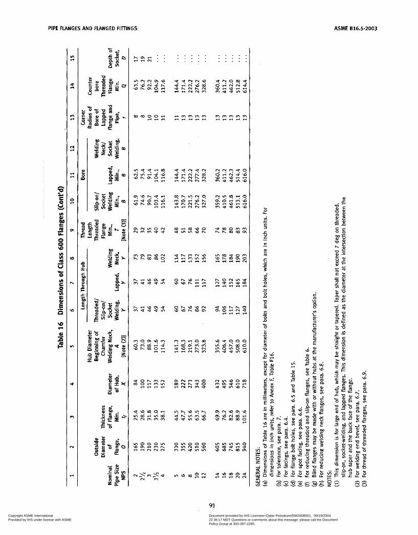
PIPE FLANGES AND FLANGED FITTINGS ASME 816.5-2003
. . h c n r i . . r i r i m . .
. . . . . . . . . . . . . . . . . . . . . . . . . . . . . .
' I \ ???? M W N V h W h c n O r i riri
m m o o r i ririri
m r i m w o e l A m W h
O h W W N W W h C o c n
U W h h O c n O r i N V
riririri
m N M M O m m h e o
m o o o m W c n r i W h r i r i N N N
N ,\" m ,y e N m
o m 0 0 0 m m m r i w m m e m m
m m m m o ocourie \ ~ w h m c n
e w m o e ririri"
91 Copyright ASME International Provided by IHS under license with ASME
Document provided by IHS Licensee=Qatar Petroleum/5943408001, 09/19/200422:36:17 MDT Questions or comments about this message: please call the DocumentPolicy Group at 303-397-2295.
--```,,`,``,,,,`,,``````,,``,`-`-`,,`,,`,`,,`---
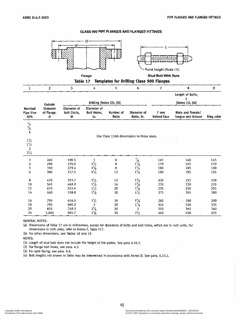
ASME 816.5-2003 PIPE FLANGES AND FLANGED FITTINGS
CLASS 900 PIPE FLANGES AND FLANGED FITTINGS
Point height [Note (111
Flange Stud Boit With Nuts
Table 17 Templates for Drilling Class 900 Flanges 1 2 3 4 5 6 7 8 9
~~~ ~~ ~
Length of Bolts, 1
Outside Drilling [Notes (21, (311 [Notes (11, (411
Nominal Diameter Diameter of Diameter of Pipe Size of flange. Bolt Circle, Bolt Holes, Number of Diameter of 7 mm Male and Female/
N PS O W in. Bolts Bolts, in. Raised Face Tongue and Groove Ring Joint
Use Class 1500 dimensions in these sizes.
3 240 190.5 1 8 'A 145 140 145 4 290 235.0 1 % 8 1 'A 170 165 170 5 350 279.4 1 3~ 8 1 190 185 190 6 380 317.5 1 12 1 'A 190 185 195
8 470 393.7 1% 12 1 58 2 20 215 220
14 640 558.8 1% 20 1% 275 265 280
18 785 685.8 2 20 1 'A 325 320 335
24 1,040 901.7 2 'A 20 2% 440 430 . 455
10 545 469.9 1% 16 1 'A 235 230 235 1 2 610 533.4 1% 20 I3A 255 250 255
16 705 616.0 1% 20 1 'A 285 280 290
20 855 749.3 2% 20 2 350 345 360
GENERAL NOTES: (a) Dimensions of Table 17 are in millimeters, except for diameters of bolts and bolt holes, which are in inch units. For
(b) For other dimensions, see Tables 18 and 19. NOTES: (1) Length of stud bolt does not include the height of the points. See para 6.10.2. (2) For flange bolt holes, see para. 6.5. (3) For spot facing, see para. 6.6. (4) Bolt lengths not shown in Table may be determined in accordance with Annex D. See para. 6.10.2.
dimensions in inch units, refer to Annex F, Table F17.
92 Copyright ASME International Provided by IHS under license with ASME
Document provided by IHS Licensee=Qatar Petroleum/5943408001, 09/19/200422:36:17 MDT Questions or comments about this message: please call the DocumentPolicy Group at 303-397-2295.
--```,,`,``,,,,`,,``````,,``,`-`-`,,`,,`,`,,`---

PIPE FLANGES AND FLANGED FIllINGS ASME 016.5-2003
P m t E
. .
C C a
n U U
c C U1
- Y
a .- UI C
.- E O
5 5i F al
E
r 7
7 r
C r
O
a
.
D
n
t
9
rl
4
al
93
Copyright ASME International Provided by IHS under license with ASME
Document provided by IHS Licensee=Qatar Petroleum/5943408001, 09/19/200422:36:17 MDT Questions or comments about this message: please call the DocumentPolicy Group at 303-397-2295.
--```,,`,``,,,,`,,``````,,``,`-`-`,,`,,`,`,,`---
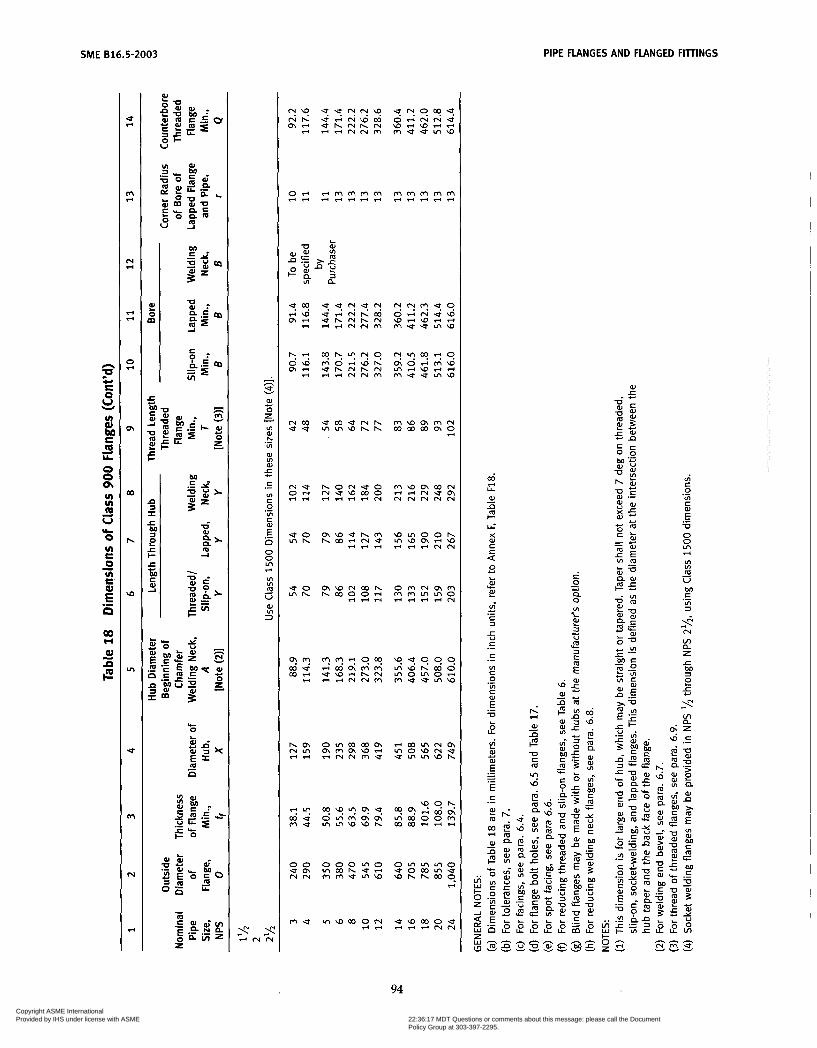
SME 816.5-2003 PIPE FLANGES AND FLANGED FITTINGS
u) u)
U 29 Yi O u) æ O u) æ .- .- E a
C J
3' z m
U a - $: m -1
e m V I C O h V r i V 0 W r n . U N N m m e r n w a h h c o o o * * - o I O 0 o o o r n o
94 Copyright ASME International Provided by IHS under license with ASME
Document provided by IHS Licensee=Qatar Petroleum/5943408001, 09/19/200422:36:17 MDT Questions or comments about this message: please call the DocumentPolicy Group at 303-397-2295.
--```,,`,``,,,,`,,``````,,``,`-`-`,,`,,`,`,,`---
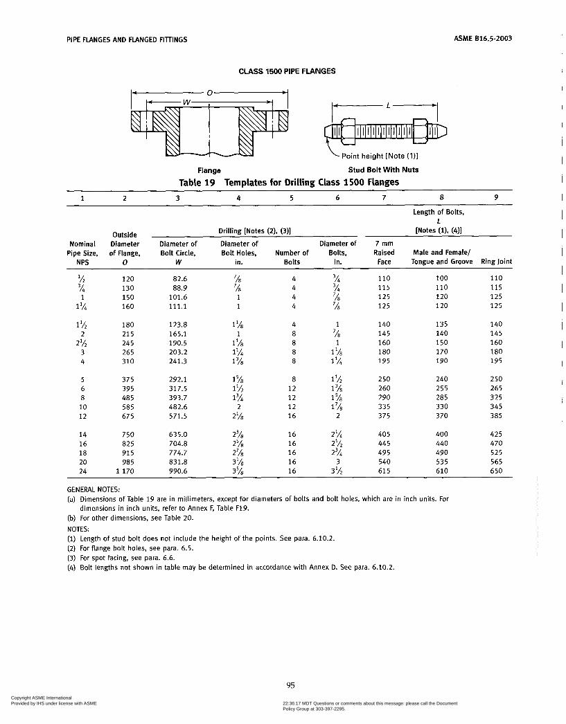
PIPE FLANGES AND FLANGED FITTINGS
CLASS 1500 PIPE FLANGES
oint height [Note (1
Flange Stud Bolt Wi th Nuts
Table 19 Templates for Drilling Class 1500 Flanges
ASME 816.5-2003
~~
1 2 3 4 5 6 7 8 9
Length of Bolts, 1
[Notes (11, (411 Drilling [Notes (2), (311
Bolt Holes, Number of Bolts, Raised Male and Female/
Outside Nominal Diameter Diameter of Diameter of Diameter of 7 mm
Pipe Size, of Flange, Bolt Circle, Face Tongue and Groove Ring Joint N PS O W in. Bolts in.
-~~~ ~ ~
% 120 82.6 % 4 3A 110 100 110 3A 130 88.9 % 4 3A 115 110 115 1 150 101.6 1 4 7h 125 120 1 2 5
1 % 160 111.1 1 4 % 125 120 125
1 27 180 123.8 l'h 4 1 140 135 140 2 21 5 165.1 1 8 7h 145 140 145
2% 245 190.5 1 'h 8 1 160 150 160 3 265 203.2 1 IL% 8 1 'h 180 170 180 4 310 241.3 1% 8 1 % 195 190 195
5 375 292.1 1 8 1 lh 250 240 250 6 395 317.5 1 Ih 12 1 260 255 265 8 485 393.7 1 3~ 12 1 5h 290 285 325
1 2 675 571.5 2'h 16 2 375 370 385 10 585 482.6 2 12 1'~ 335 330 345
14 750 635.0 23/s 16 2% 405 400 425 16 825 704.8 z5/s 16 2% 445 440 470 18 915 774.7 2% 16 2% 495 490 525 20 985 831.8 3'43 16 3 540 535 565 24 1 1 7 0 990.6 35h 16 3 lh 61 5 610 650
GENERAL NOTES: (a) Dimensions of Table 15 are in millimeters, except for diameters of bolts and bolt holes, which are in inch units. For
dimensions in inch units, refer to Annex F, Table F19. (b) For other dimensions, see Table 20.
NOTES: (i) Length of stud bolt does not include the height of the points. See para. 6.10.2. (2) For flange bolt holes, see para. 6.5. (3) For spot facing, see para. 6.6. (4) Bolt lengths not shown in table may be determined in accordance with Annex D. See para. 6.10.2.
95 Copyright ASME International Provided by IHS under license with ASME
Document provided by IHS Licensee=Qatar Petroleum/5943408001, 09/19/200422:36:17 MDT Questions or comments about this message: please call the DocumentPolicy Group at 303-397-2295.
--```,,`,``,,,,`,,``````,,``,`-`-`,,`,,`,`,,`---
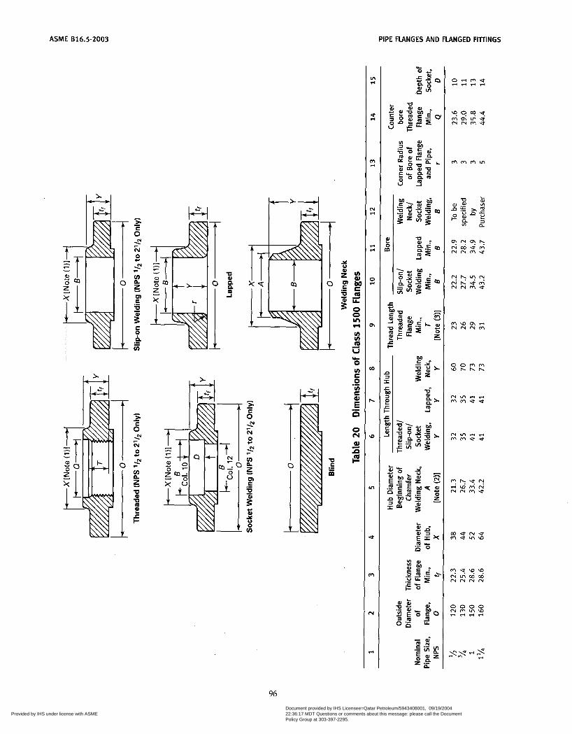
ASME 816.5-2003 PIPE FLANGES AND FLANGED FiìTiNGS
I
8 .- u] C al E n .- o N al d a F
96 Copyright ASME International Provided by IHS under license with ASME
Document provided by IHS Licensee=Qatar Petroleum/5943408001, 09/19/200422:36:17 MDT Questions or comments about this message: please call the DocumentPolicy Group at 303-397-2295.
--```,,`,``,,,,`,,``````,,``,`-`-`,,`,,`,`,,`---

PIPE FLANGES AND FLANGED FIllIHGS ASME 016.5-2003
. . \ D h a . . r i & + . .
. . . . . . . . . . . . . . . . . . . . . . . . . . . Ln
ri
5
m ri
N ri
ri ri
O %-I
m
m
h
rD
In
m
N
ri
. . . . . . . . . . . . . . . . . . . . . . . . . . . . . .
r n m m m r n r i & - - -
n
E P U
8 12 E
5:
Y
m LL
O
H u) u) m v * O u) C O u) E
d
d
.-
.- E" n O hl a# s d cm
. . . . . . . . . . . . . . . . . . . . . . . . . . . . . .
. . m m m . . M M U . .
. . . . . . . . . . . . . . . . . . . . . . . . . . . . . .
r i O W N O U W h o \ M N N N N M c
O
O VI
.- Y n
L
E
L
3 U
3 c
Y
E
. u m w : : . . . . . . . . . . . . . . .
. . . . . . . . . . . . . . .
M M + O ~ w . u o o 0
O V I U M N h O N M W
- r i e r i
o m m m o m - u w - r i N N N M
97 Copyright ASME International Provided by IHS under license with ASME
Document provided by IHS Licensee=Qatar Petroleum/5943408001, 09/19/200422:36:17 MDT Questions or comments about this message: please call the DocumentPolicy Group at 303-397-2295.
--```,,`,``,,,,`,,``````,,``,`-`-`,,`,,`,`,,`---
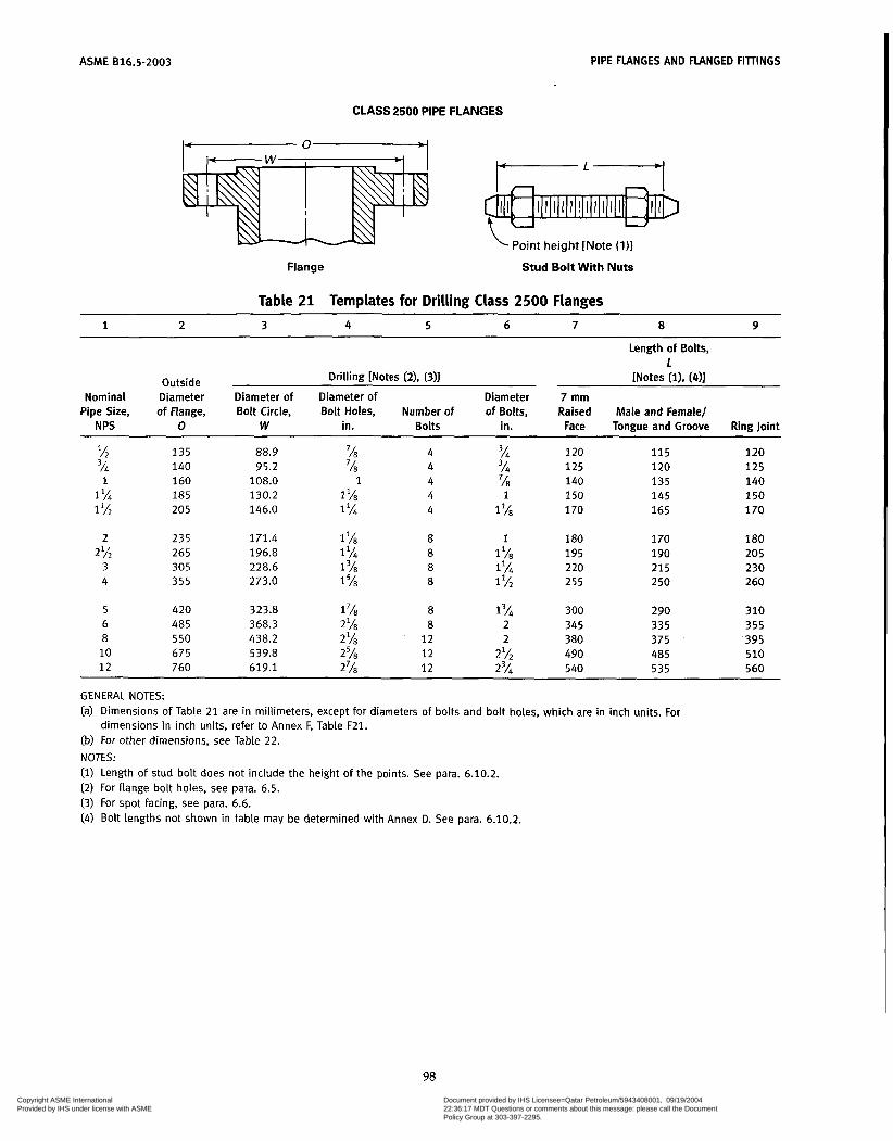
ASME 816.5-2003 PIPE FLANGES AND FLANGED FIllINGS
CLASS 2500 PIPE FLANGES
Point height [Note (l)]
Flange Stud Bolt W i t h Nuts
Table 21 Templates for Drilling Class 2500 Flanges ~
1 2 3 4 5 6 7 8 9
Outside Nominal Diameter
Pipe Size, of Flange, N PS O
Drilling [Notes (2). (311
Diameter of Diameter of Diameter Bolt Circle, Bolt Holes, Number of of Bolts,
W in. Bolts in. ~~
2 135 3/i 140 1 160
1% 185 1 IA 205
~ ~~ ~~ ~ ~
88.9 %3 4 % 95.2 7h 4 3/4
108.0 1 4 'h 130.2 1 'h 4 1 146.0 1 '/i 4 1 'h
Length of Bolts, 1
[Notes (i). (411
7 mm Raised Male and Female/ Face Tongue and Groove Ring Joint
120 115 120 1 2 5 120 125 140 135 140 150 145 150 170 165 170
2 235 171.4 1 'h 8 1 180 170 180 2% 265 196.8 1 'Al 8 1 'h 195 190 205
3 305 228.6 1 3~ 8 1% 220 215 230 4 355 273.0 1 8 1 lh 255 2 50 260
5 420 323.8 1 8 1 3/4 300 290 310 6 485 368.3 2h 8 2 345 335 355 8 550 438.2 2'h 12 2 3 80 375 395 10 675 539.8 25h 1 2 2 'h 490 485 510 1 2 760 619.1 27/s 12 23/4 540 535 560
GENERAL NOTES: (a) Dimensions of Table 21 are in millimeters, except for diameters of bolts and bolt holes, which are in inch units. For
(b) For other dimensions, see Table 22. NOTES: (1) Length of stud bolt does not include the height of the points. See para. 6.10.2. (2) For flange bolt holes, see para. 6.5. (3) For spot facing, see para. 6.6. (4) Bolt lengths not shown in table may be determined with Annex D. See para. 6.10.2.
dimensions in inch units, refer to Annex F, Table F21.
98 Copyright ASME International Provided by IHS under license with ASME
Document provided by IHS Licensee=Qatar Petroleum/5943408001, 09/19/200422:36:17 MDT Questions or comments about this message: please call the DocumentPolicy Group at 303-397-2295.
--```,,`,``,,,,`,,``````,,``,`-`-`,,`,,`,`,,`---
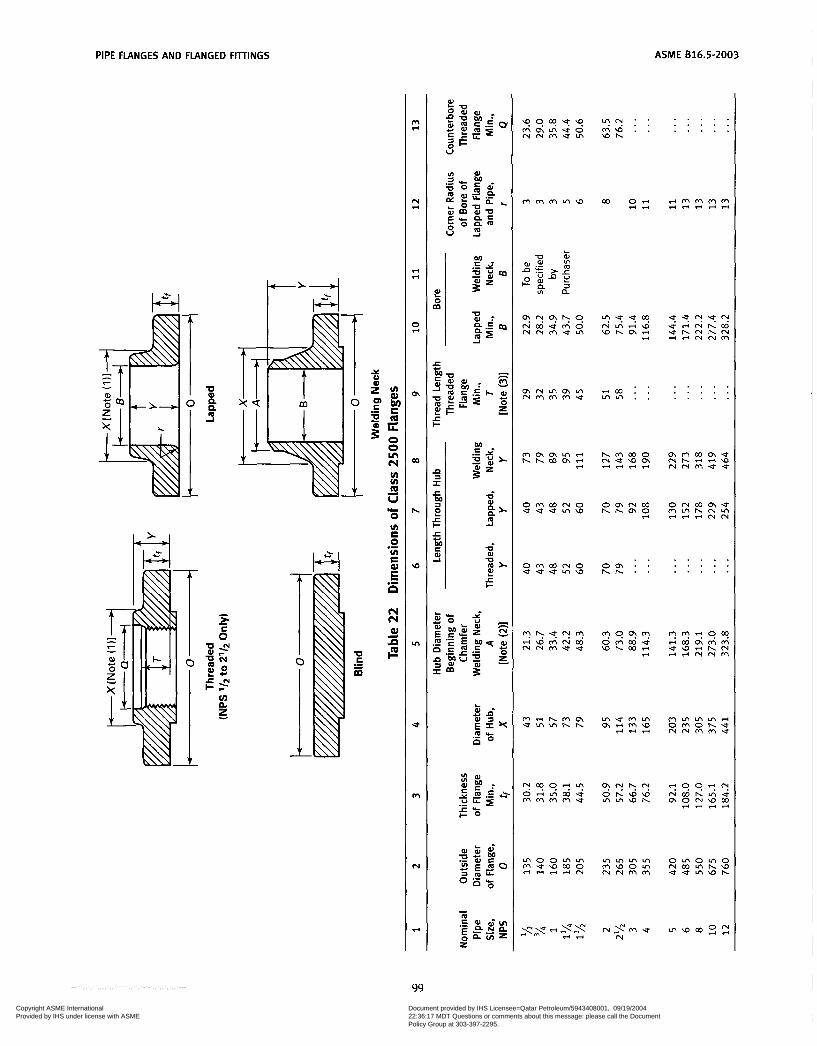
PIPE FLANGES AND FLANGED FIllINGS ASME 016.5-2003
. . . . . . . . . . . . . . . m *
N *
* *
O *
Qi
m
h
W
In
U
rn
N
ri
? N : : m a . . a h
m m m m w
t-'4 I .
z n m Q A
. . r i m . . m m . .
. . . . . . . . . . . . . . . m r u m m m m m m m u
o m m r u o u u u m a o m m m h h m o
ri
. . . . . . . . . . . . . . . o m m m o u u u m w
m o o m m r i l - l - r i m m u w m o m m m m
m w o m m m m m o m o m o m m m h w U u r n w h
m . Y m u m
99 Copyright ASME International Provided by IHS under license with ASME
Document provided by IHS Licensee=Qatar Petroleum/5943408001, 09/19/200422:36:17 MDT Questions or comments about this message: please call the DocumentPolicy Group at 303-397-2295.
--```,,`,``,,,,`,,``````,,``,`-`-`,,`,,`,`,,`---
AS M E B16.5-2003 PIPE FLANGES AND FLANGED FITTINGS
Notes to Table 22 GENERAL NOTES: (a) Dimensions of Table 22 are in milimeters, except for diameter of bolts and bolt holes, which are in inch units. For
dimensions in inch units, refer to Annex F, Table F22. (b) For tolerances, see para. 7. (c) For facings, see para. 6.4. (d) For flange bolt holes, see para. 6.5 and Table 21. (e) For spot facing, see para 6.6. (0 For reducing threaded and slip-on flanges, see Table 6. (g, Blind flanges may be made with or without hubs at the manufacturer’s option. (h) For reducing welding neck flanges, see para 6.8. NOTES: (1) This dimension is for large end of hub, which may be straight or tapered. Taper shall not exceed 7 deg on threaded,
slip-on, socket-welding, and lapped flanges. This dimeniion is defined as the diameter at the intersection between the hub taper and the back face of the flange.
(2) For welding end bevel, see para. 6.7. (3) For thread of threaded flanges, see para. 6.9.
100
Copyright ASME International Provided by IHS under license with ASME
Document provided by IHS Licensee=Qatar Petroleum/5943408001, 09/19/200422:36:17 MDT Questions or comments about this message: please call the DocumentPolicy Group at 303-397-2295.
--```,,`,``,,,,`,,``````,,``,`-`-`,,`,,`,`,,`---
ASME 816.5-2003
ANNEX A THREADING OF PIPE FOR AMERICAN
NATIONAL STANDARD THREADED FLANGES'
The length of external taper threads in ACME B1.20.1 is sufficient to provide a satisfactory joint when assem- bled with corresponding internal taper threads in cou- plings and fittings. In this Standard, the length of internal thread in Class 150, Class 300, and Class 400 flanges also conforms to ACME B1.20.1.
In Class 600 and higher rated flanges, the length through the hub may exceed the length for internal threads in ACME B1.20.1. Where this occurs, the extended length of internal threads follows the taper of the standard taper threads. Therefore, the diameters of the extra threads are smaller than those shown in ACME 81.20.1.
When threaded flanges conforming to this Standard are assembled with threaded-end pipe, it is intended that the end of the pipe be reasonably close to the mating
' This Annex is an integral part of ASME B16.5-2003, and is placed after the main text for convenience.
surface of the flange. To meet this intent, the following requirements are imposed on the mating pipe and exter- nal thread:
(u) Pipe to be threaded into flanges of Class 600 or higher rating shall be Schedule 80 or heavier in wall thickness.
(b) The length of external effective thread on the pipe end shall be greater than specified in ACME B1.20.1. When tested with the standard ring gage, the pipe end shall project beyond the gage by the distance specified in Table Al, subject to a tolerance of one thread pitch as provided in ACME B1.20.1.
(c) The extra threads shail continue the taper specified in ACME B1.20.1, so that the pitch diameter of the thread at the pipe end is less than specified therein.
(d) It is recommended that power equipment be used to assemble threaded joints having longer than standard taper threads, in order to bring the pipe end close to the flange face.
101 Copyright ASME International Provided by IHS under license with ASME
Document provided by IHS Licensee=Qatar Petroleum/5943408001, 09/19/200422:36:17 MDT Questions or comments about this message: please call the DocumentPolicy Group at 303-397-2295.
--```,,`,``,,,,`,,``````,,``,`-`-`,,`,,`,`,,`---
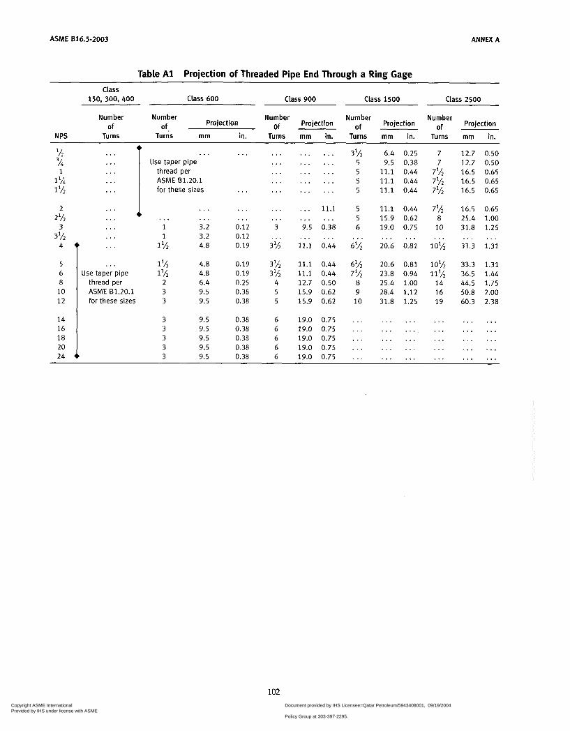
ASME 816.5-2003 A N N U A
Table A l Projection of Threaded Pipe End Through a Ring Gage
Class 150, 300, 400 Class 600 Class 900 Class 1500 Class 2500
Number Number Number Number Number Projection Of Projection of Projection of Projection
of of. N PS Turns Turns rnm in. Turns mm in. Turns mm in. Turns mrn in.
% ... % . . . 1 . . .
1% . . . 1 l/2 . . .
2 . . .
3 . . . 2% . . .
3 l h . . .
t . . . . . .
8 thread per
. . . Use taper pipe
thread per ASME 81.20.1 for these sizes
. . . . . . . . . 1 3.2 1 3.2
1 Y2 4.8
1 4.8 1 l/2 4.8
2 6.4
I . . .
. . .
. . .
. . . 0.12 0.12 0.19
0.19 0.19 0.25
ASME B1.20.1 3 9.5 0.38 for these sizes 3 9.5 0.38
18
24 20 I 3 9.5 0.38
3 9.5 0.38 3 9.5 0.38 3 9.5 0.38 3 9.5 0.38
. . .
...
...
. . .
...
. . .
... 3
. . . 3%
3% 3 l h
4 5 5
6 6 6 6 6
. . . . . .
. . . . . .
. . . . . .
. . . . . .
. . . . . .
. . . 11.1
9.5 0.38
11.1 0.44
11.1 0.44 11.1 0.44 12.7 0.50 15.9 0.62 15.9 0.62
19.0 0.75 19.0 0.75 19.0 0.75 19.0 0.75 19.0 0.75
. . . . . .
. . . . . .
3% 5 5 5 5
5 5 6
6%
6%
. . .
7% 8 9 10
. . .
. . .
. . .
...
...
6.4 0.25 7 9.5 0.38 7
11.1 0.44 7% 11.1 0.44 7% 11.1 0.44 7%
11.1 0.44 7% 15.9 0.62 8 19.0 0.75 10
20.6 0.81 10%
20.6 0.81 10% 23.8 0.94 11% 25.4 1.00 14 28.4 1.12 16 31.8 1.25 19
. . . . . . . . .
. . . . . . ...
. . . . . .
. . . . . .
. . . . . . ...
. . . . . . . . .
12.7 0.50 12.7 0.50 16.5 0.65 16.5 0.65 16.5 0.65
16.5 0.65 25.4 1.00 31.8 1.25
33.3 1.31
33.3 1.31 36.5 1.44 44.5 1.75 50.8 2.00 60.3 2.38
. . . . . .
. . . . . .
. . . . . .
. . . . . .
. . . . . .
. . . . . .
102 Copyright ASME International Provided by IHS under license with ASME
Document provided by IHS Licensee=Qatar Petroleum/5943408001, 09/19/200422:36:17 MDT Questions or comments about this message: please call the DocumentPolicy Group at 303-397-2295.
--```,,`,``,,,,`,,``````,,``,`-`-`,,`,,`,`,,`---

ASME 816.5-2003
ANNEX B METHOD USED FOR ESTABLISHING
PRESSU RE-TEMPERATU RE RATINGS'
B1 GENERAL CONSIDERATIONS
Bl.1 Introduction Pressure-temperature ratings for this Standard have
been determined by the procedures described in this Annex. These procedures are counterpart to those identi- fied as Standard Class in ACME B16.34. The primary considerations in establishing ratings are component dimensions and material properties to sustain pressure and other loads? Other considerations affecting or lim- iting ratings include
(u) stresses in flanges resulting from bolt-up necessary to maintain a gasket seal
(b) distortion of flanges and flanged fittings due to loads transmitted through attached piping
(c) limitations applying primarily to flanged compo- nents (e.g., valves), but also imposed on flanges in order to preserve compatible ratings
81.2 Bolt Cross-sectional Area
are based on the following relationship Total flange bolting cross-sectional area requirements
where Ab = total effective bolt tensile stress area Ag = an area whose circumference is defined by a
diameter equal to the raised face dimension R in Table 4
P, = pressure rating class designation or number (e.g., for Class 150, P, = 150; for Class 300, P, = 300)
B1.3 Flanged Fitting Wall Thickness Wall thickness requirements for flanged fittings are
specified in para. 6.1. The minimum wall thickness val- ues t, are shown in the tables designated in para. 6.1. These values are all greater than those determined by Eq. (2).
This Annex is an integral part of ASME B16.5-2003, and is placed
This method is appropriate for materials listed in Table 1A. It after the main text for convenience.
may not be appropriate for other materials.
r 1
t = 1.51 2SF p p -1.2Pc J where P, = pressure rating class designation or number
( e g , for Class 150, P, = 150; for Class 300, P, = 300)
SF = stress base constant equal to 7000 d = inside diameter of the fitting t = calculated thickness
The resultant units for t will be the same as those used to express d. Equation (2) results in a fitting wall thickness 50% greater than that for a simple cylinder designed for a stress of 48.28 MPa (7000 psi) when sub- jected to an internal pressure equal to the pressure rating class designation P,. The actual values in the dimension tables referred to in para. 6.1 are approximately 2.5 mm (0.1 in.) larger than those given by the equation.
B1.4 Material Properties The pressure-temperature rating method uses allow-
able stress, ultimate tensile strength, and yield strength values from Section II, Part D of the ACME Boiler and Pressure Vessel Code. For materials listed herein that have ratings either at temperature values that are above those shown in a reference Code Section or that are not listed in any of the reference Code Sections, the allow- able stress, ultimate tensile strength, and yield strength data have been provided directly by the ACME Boiler and Pressure Vessel Subcommittee on Materials.
B1.5 Material Groups Materials are grouped in Table 1A based on identical
or closely matched allowable stress and yield strength values. When these values are not identical for each material listed, the lowest value has been used. Note that material groups in this Standard are not numbered consecutively. The unlisted numbers, numbers that are not part of this Standard may be found in the materials tables of ACME B16.34.
82 PRESSURE-TEMPERATURE RATING METHOD B2.1 Rating Equation Class 300 and Higher
Pressure-temperature ratings for Class 300 and higher components, of materials listed to those in Table lA, were established by the equation
103
Copyright ASME International Provided by IHS under license with ASME
Document provided by IHS Licensee=Qatar Petroleum/5943408001, 09/19/200422:36:17 MDT Questions or comments about this message: please call the DocumentPolicy Group at 303-397-2295.
--```,,`,``,,,,`,,``````,,``,`-`-`,,`,,`,`,,`---
ASME 816.5-2003 ANNEX B
where c1 =
P, =
si =
P c =
Pf =
(3)
10 when Si is expressed in MPa units and the resultant pf will be in bar units (Cl = 1 when SI is expressed in psi units and the resultant p f will be in psi units) pressure rating class index. For all designations Class 300 and above, P, is equal to the class designation (e.g., for Class 300, P, = 300). (For Class 150, see para. B2.4 of this Annex.) selected stress, MPa (psi) for the specified mate- rial at temperature T. The value of Si shall be established as described in paras. B2.2, 82.3, and B2.4. ceiling pressure, bar (psi), at temperature T as specified in para. B3 rated working pressure, bar (psi), for the speci- fied material at temperature T
82.2 Ratings for Group No. 1 Materials
1A is determined as follows:
equal to or less than
38°C (100°F)
The selected stress for Group No. 1 materials in Table
(u) At temperatures below the creep range S1 shall be
(1) 60% of the specified minimum yield strength at
(2) 60% of the yield strength at temperature T (3) 1.25 times 25% of the ultimate tensile strength
value at temperature T, as listed in Section II, Part D of the ACME Boiler and Pressure Vessel Code for either Section 1 or Section VIII, Division 1.
(b) At temperatures in the creep range, the value of Si shall be the allowable stress at temperature T, as listed in Section 11, Part D of the ACME Boiler and Pressure Vessel Code, for either Section I or Section VIII, Division 1; but not exceeding 60% of the listed yield strength at temperature.
(c) In no case shall the selected stress value increase with increasing temperature.
( d ) The creep range is considered to be at tempera- tures in excess of 370°C (700°F) for Group 1 materials.
(e) When the allowable stresses listed for the reference ACME Boiler and Pressure Vessel Code Section show a higher and lower value for allowable stress and the higher value is noted to the effect that these stress values exceed two-thirds of the yield strength at temperature, then the lower value shall be used. If lower allowable stress values do not appear and it is noted in the allow- able stress table that the allowable stress values exceed two-thirds of the yield strength at temperature, then the allowable stress values used shall be determined as two- thirds of the tabulated yield strength at temperature. cf, Yield strength shall be as listed in Section II, Part
D of the ACME Boiler and Pressure Vessel Code, for either Section III or Section VIU, Division 2.
(g) Allowable stress values listed in Section II, Part D of the ASME Boiler and Pressure Vessel Code, for Section III, Class 2 or Class 3 values may only be used for a material not listed for either Section I or Section VIII, Division 1.
62.3 Method for Groups 2 and 3 Materials Pressure-temperature ratings for Class 300 and
higher, of materials corresponding to those in Materials Groups 2 and 3 of Table 1A are established by the method of paras. B2.1 and 82.2, except that in paras. B2.2(a)(l) and B2.2(a)(2), the 60% factor shall be changed to 7û0/0. For Group 2 materials, the creep range is considered to be at temperatures in excess of 510°C (950°F) unless the material properties indicate lower temperatures should be used. For Group 3 materials, the creep range onset temperature shall be determined on an individual basis.
B2.4 Method for Class 150 - All Materials Pressure-temperature ratings for Class 150 rating des-
ignation are established by the method given for the related materials in paras. 82.1, B2.2, and B2.3 subject to the following exceptions:
(a) The value of P , the pressure class rating index in Eq. (2) for Class 150, shall be 115.
(b) The value for Si the selected stress MPa (psi) for the specific material at temperature T shall be in accor- dance with the requirements of either para. B2.1 or B2.2, as applicable.
(c) The value of p, , the rated working pressure bar (psi), for Class 150, shall not exceed values at tempera- ture T as given by Eq. (4).
(4) ~t < C2 - C3T
where: C2 = 21.41 C3 = 0.03724 with T expressed in OC, the resultant
pf will be in bar units (C, = 320 and C3 = 0.3, with T expressed in OF, the resultant p f will be in psi units)
T = material temperature, "C (OF)
The value of T in Eq. (4) shall not exceed 538°C (1000'F). For values of T less than 38°C (100"F), use T equal to 38°C (100°F) in Eq. (4).
63 MAXIMUM RATINGS
The rules for establishing pressure-temperature rat- ings include consideration of ceiling pressures pc that effectively set limits on the selected stress. The ceiling pressure-temperature values set an upper bound for high strength materials and are imposed to limit deflec- tion. Ceiling pressure values are listed in Tables B1 and B2. Ratings in excess of these ceiling values are not permitted under this Standard.
104
Copyright ASME International Provided by IHS under license with ASME
Document provided by IHS Licensee=Qatar Petroleum/5943408001, 09/19/200422:36:17 MDT Questions or comments about this message: please call the DocumentPolicy Group at 303-397-2295.
--```,,`,``,,,,`,,``````,,``,`-`-`,,`,,`,`,,`---

ANNEX B ASME 016.5-2003
Table 61 Rating Ceiling Pressure pc, bar CLASS
Temperature Class Class Class Class Class Class Class OC 150 300 400 600 900 1500 2500
-29 to 38 20.0 51.7 68.9 103.4 155.1 258.6 430.9 50 19.5 51.7 68.9 103.4 155.1 258.6 430.9
100 17.7 51.5 68.7 103.0 154.6 257.6 429.4
200 13.8 48.6 64.8 97.2 145.8 243.4 405.4 150 15.8 50.3 66.8 100.3 150.6 250.8 418.2
250 12.1 46.3 61.7 92.7 139.0 23 i .a 386.2 300 10.2 42.9 57.0 85.7 i 28.6 214.4 357.1 325 9.3 41.4 55.0 82.6 124.0 206.6 344.3 350 8.4 40.3 53.6 80.4 120.7 201.1 335.3 375 7.4 38.9 51.6 77.6 116.5 194.1 323.2
400 6.5 36.5 48.9 73.3 109.8 183.1 304.9 425 5.5 35.2 46.5 70.0 105.1 175.1 291.6 450 4.6 33.7 45.1 67.7 101.4 169.0 281.8 475 3.7 31.7 42.3 63.4 95.1 158.2 263.9 500 2.8 28.2 37.6 56.5 84.7 140.9 235.0
525 1.9 25.8 34.4 51.6 77.4 129.0 214.9 538 1.4 25.2 33.4 50.0 75.2 125.5 208.9 550 (1) 25.0 33.3 49.8 74.8 124.9 208.0 575 (1) 24.0 31.9 47.9 71.8 119.7 199.5 600 (1) 21.6 28.6 42.9 64.2 107.0 178.5
625 (1) 18.3 24.3 36.6 54.9 91.2 152.0 650 (1) 14.1 18.9 28.1 42.5 70.7 117.7 675 (1) 12.4 16.9 25.2 37.6 62.7 104.5
725 (1) 7.9 10.5 15.4 23.2 38.6 64.4 700 (1) 10.1 13.4 20.0 29.8 49.7 83.0
750 (1) 5.9 7.9 11.7 17.6 29.6 49.1
ao0 (1) 3.5 4.8 7.0 10.5 17.4 29.2 775 (1) 4.6 6.2 9.0 13.7 22.8 38.0
816 (1) 2.8 3.8 5.9 8.6 14.1 23.8 ~ ~ ~ ~ ~ ~~
NOTE: (1) Ratings for flanges and flanged fittings terminate at 538OC (lOOO°F).
105
Copyright ASME International Provided by IHS under license with ASME
Document provided by IHS Licensee=Qatar Petroleum/5943408001, 09/19/200422:36:17 MDT Questions or comments about this message: please call the DocumentPolicy Group at 303-397-2295.
--```,,`,``,,,,`,,``````,,``,`-`-`,,`,,`,`,,`---

ASME B16.5-2003 ANNEX B
Table B2 Rating Ceiling Pressure - pc, psi ~ ____ ~~
Class
Temperature Class Class Class Class Class Class Class O F 150 300 400 600 900 1500 2500
-20 to 100 200 300 400 500
290 260 230 200 170
750 750 730 705 665
1000 1000 970 940 a85
1500 1500 1455 1410 1330
2250 2250
2115 1995
2185
3750 3750 3640 3530 3325
6250 6250 6070
5540 5880
600 650 700 750 800
140 125 110 95 80
605 590 570 530 510
ao5 785 75 5 710 675
1210 1175 1135 1065 1015
ia15 1765 1705 1595 1525
3025 2940
2660 2540
2840
5040 4905 4730 4430 4230
a50 900 950
1000 1050
65 50 35 20 (1)
485
385 450
365 360
650 600 51 5 485 480
975 900 775 725 720
1460 1350 1160 1090 ioao
2435 2245 1930
1800 ia20
4060 3745 3220 3030 3000
1100 1150 1200 1250
325 275 205 i ao
430 365 275 245
965
620 545
a25 645 550 410 365
1610 1370 1030 910
1300 1350 1400 1450 1500
140 105
75 60 40
i a 5
ao
140 100
55
275 205 150 1 1 5 85
410 310 225 175 125
685 515
290 205
380
1145
630
345
a60
485
~
NOTE: (1) Ratings of flanges and flanged fittings terminate at 1000°F (538OC).
106 Copyright ASME International Provided by IHS under license with ASME
Document provided by IHS Licensee=Qatar Petroleum/5943408001, 09/19/200422:36:17 MDT Questions or comments about this message: please call the DocumentPolicy Group at 303-397-2295.
--```,,`,``,,,,`,,``````,,``,`-`-`,,`,,`,`,,`---
ASME 816.5-2003
ANNEX C LIMITING DIMENSIONS OF GASKETS OTHER THAN RING JOINT GASKETS'
C i GASKET MATERIALS AND CONSTRUCTION
Classification of Gasket Materials and types is shown in Table C1. Other gaskets that result in no increase in bolt loads or ffange moment over those resulting from the gaskets included in the respective Groups may be used. See para. 5.4
C2 GASKET DIMENSIONS Reference to a dimensional standad for gaskets (e.g.,
ACME B16.21) is recommended. In any event, selected
This Annex is not a mandatory annex of ACME 816.5-2003, and is placed after the main text for information.
dimensions should be based on the type of gasket and its characteristics. These characteristics include density, flexibility, compatibility with the fluid being contained and gasket compression needed to maintain sealing. Consideration should be given to the need for a "pocket" at the gasket inside diameter (between the flange fac- ings) or of intrusion of the gasket into the ffange bore. Consideration should also be given to the effects that the contained fluid may have upon the gasket including damage that may result from partial disintegration of the gasket material.
107
Copyright ASME International Provided by IHS under license with ASME
Document provided by IHS Licensee=Qatar Petroleum/5943408001, 09/19/200422:36:17 MDT Questions or comments about this message: please call the DocumentPolicy Group at 303-397-2295.
--```,,`,``,,,,`,,``````,,``,`-`-`,,`,,`,`,,`---

ASME 616.5-2003 ANNEX C
Table C1 Gasket Groups and Typical Materials
Gasket Group
Number Gasket Material Sketches
la Self-energizing types: O rings, metallic, elastomer, other gasket types considered as self-sealing
0 LZ3
Elastomer without fabric
Compressed sheet suitable for the operating conditions
Fluoropolymer, Elastomer with cotton fabric insertion a Elastomer with or without wire reinforcement a Vegetable fiber e
Ib Spiral-wound metal, with nonmetallic filler
Corrugated aluminum, copper or copper alloy or AziQ e corrugated aluminum, copper or copper alloy double jacketed with nonmetallic filler
Corrugated aluminum, copper, or brass
Corrugated metal or corrugated metal double jacketed Ila and lib
&EV Corrugated metal A Z v
with nonmetallic filler
Flat metal jacketed with nonmetallic filler
Grooved metal Solid flat soft aluminum
€2 Illa and Illb Solid flat metal
Ring joint
108
Copyright ASME International Provided by IHS under license with ASME
Document provided by IHS Licensee=Qatar Petroleum/5943408001, 09/19/200422:36:17 MDT Questions or comments about this message: please call the DocumentPolicy Group at 303-397-2295.
--```,,`,``,,,,`,,``````,,``,`-`-`,,`,,`,`,,`---
ASME 816.5-2003
ANNEX D METHOD FOR CALCULATING BOLT LENGTHS'. *
The following equations were used in establishing dimension L as listed in various dimensional tables. For lapped joints, calculate stud bolt and machine bolt lengths as follows.
B = 2(tf + t) + d + G + F + p - u (i.e., machine bolt length exclusive of negative tolerance n)
F = total height of facings or depth of ring joint groove for both flanges (see Table D1)
G = 3.0 mm (0.12 in.) gasket thickness for raised face, male and female tongue and groove flanges; also approximate distance between ring joint flanges listed in Table 5 (Table F5 of
L C ~ B = A + n For ring joint groove facing:
SB = A + (pipe thickness for each lap) + n
~ M B = B + (pipe thickness for each lap) + n
LCMB = B + n
For other than ring joint facing:
ksB = A - ï + (Table D3 thicknesses) + II .
LCMB = B - F + (Table D3 thicknesses) + n
where: A = 2(tf + t + d ) + G + F - u (i.e., stud bolt length
exclusive of negative length tolerance n)
This Annex is not a mandatory annex of ACME 816.5-2003 and is placed after the main text for information.
The equations used in this Annex are for calculated bolt lengths established to ensure full thread engagement of heavy hexagon nuts when worst case tolerances occur on all relevant dimensions of the flanged joint. The use of shorter bolt lengths is acceptable provided that full thread engagement is obtained at assembly (see para. 6.10.2).
Annex F) LCMB = calculated machine bolt length as measured
from underside of head to end of point LCSB = calculated stud bolt length (effective thread
length, excluding end points) LsMB = specified machine bolt length (from underhead
to end, including end point), which is LCMB
rounded off to the nearest 5 mm (0.25 in.) incre- ment (see Fig. D2)
LSSB = specified stud bolt length (effective thread length, excluding end points) which is LcsB rounded off to the nearest 5 mm (0.25 in.) incre- ment (see Fig. D1)
a = zero, except where the small female face is on the end of pipe, u = 5 mm (0.19 in.)
d = heavy nut thickness (equals nominal bolt diam- eter, see ACME B18.2.2)
n = negative tolerance on bolt length (see Table D2) p = allowance for height of point of machine bolt
t = plus tolerance for flange thickness (see para. 7.3) = minimum flange thickness (see applicable
(1.5 times thread pitch)
dimensional tables)
109
Copyright ASME International Provided by IHS under license with ASME
Document provided by IHS Licensee=Qatar Petroleum/5943408001, 09/19/200422:36:17 MDT Questions or comments about this message: please call the DocumentPolicy Group at 303-397-2295.
--```,,`,``,,,,`,,``````,,``,`-`-`,,`,,`,`,,`---
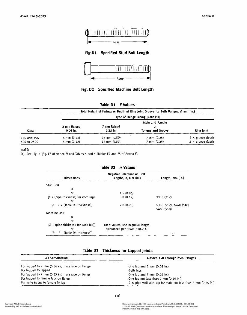
ASME 816.5-2003
nil I I I I I I I I l I I I I I l l I I I l I I I I I I I I I I in ANNEX D
Fig.Dl Specified Stud Bolt Length
K I I I I I I I I I I I I I I I I I I ID
Fig. D2 Specified Machine Bolt length
Table D1 F Values
Total Height of Facings or Depth of Ring Joint Groove for Both Flanges, F, mm (in.)
Tvoe of Flange Facing INote (D1 Male and Female
2 mm Raised 7 mrn Raised or Class 0.06 in. 0.25 in. Tongue and Groove Ring Joint
150 and 300 4 mm (0.12) 14 mrn (0.50) 400 to 2500 4 mm (0.12) 14 mrn (0.50)
7 mrn (0.25) 7 mrn (0.25)
2 x groove depth 2 x groove depth
NOTE (1) See Fig. 8 (Fig. F8 of Annex F) and Tables 4 and 5 (Tables F4 and F5 of Annex F).
Table D2 n Values Negative Tolerance on Bolt
Dimensions Lengths, n, mrn (in.) Length, mrn (in.)
Stud Bolt A or 1.5 (0.06)
[A + (pipe thickness) for each lap)] 3.0 (0.12) or
[A - F + (Table D3 thickness)] 7.0 (0.25)
Machine Bolt B or
[B + (pipe thickness for each lap)] or tolerances per ASME 818.2.1.
[B - i + (Table D3 thickness)]
For n values, use negative length
. . .
Table D3 Thickness for Lapped Joints
Lap Combination Classes 150 Through 2500 Flanges
For lapped to 2 mm (0.06 in.) male face on flange For lapped to lapped For lapped to 7 mm (0.25 in.) male face on flange For lapped to female face on flange For maie in lap to female in lap
One lap and 2 mm (0.06 in.) Both laps One lap and 7 mm (0.25 in.) One lap not less than 7 rnm (0.25 in.) 2 X pipe wall with lap for male not less than 7 mm (0.25 in.)
110
Copyright ASME International Provided by IHS under license with ASME
Document provided by IHS Licensee=Qatar Petroleum/5943408001, 09/19/200422:36:17 MDT Questions or comments about this message: please call the DocumentPolicy Group at 303-397-2295.
--```,,`,``,,,,`,,``````,,``,`-`-`,,`,,`,`,,`---
ASME 816.5-2003
ANNEX E QUALITY SYSTEM PROGRAM’
The products manufactured in accordance with this Standard shall be produced under a quality system pro- gram following the principles of an appropriate stan- dard from the IS0 9000 series? A determination of the
This Annex is an integral part of ASME B16.5-2003, and is placed after the main text for convenience.
The series is also available from the American National Ctan- dards Institute (ANSI) and the American Society for Quality Con- îrol (ASQC) as American National Standards that are identified by a prefix “ Q , replacing the prefix ”ISO.” Each standard of the series is listed under Annex H, References.
need for registration and/or certification of the product manufacturer’s quality system program by an indepen- dent organization shall be the responsibility of the man- ufacturer. The detailed documentation demonstrating program compliance shall be available to the purchaser at the manufacturer’s facility. A written summary description of the program utilized by the product man- ufacturer shall be available to the purchaser upon request. The product manufacturer is defined as the entity whose name or trademark appears on the product in accordance with the marking or identification require- ments of this Standard.
111
Copyright ASME International Provided by IHS under license with ASME
Document provided by IHS Licensee=Qatar Petroleum/5943408001, 09/19/200422:36:17 MDT Questions or comments about this message: please call the DocumentPolicy Group at 303-397-2295.
--```,,`,``,,,,`,,``````,,``,`-`-`,,`,,`,`,,`---
ASME 816.5-2003
ANNEX F
FOR CLASSES 150,300,400,600,900,1500, AND 2500 FLANGES AND CLASSES 150 AND 300 FLANGED FITTINGS IN
U.S. CUSTOMARY UNITS
PRESSURE-TEMPERATURE RATINGS AND DIMENSIONAL DATA
This Annex is an integral part of ASME B16.5-2003, and is placed after the main text for convenience.
The pressure-temperature ratings for the materials listed in Table 1A and covered by this Standard, are as listed in Tables 2-1.1 through 2-3.17 and Tables F2-1.1 through F2-3.17 of of this Annex.
Tables 2-1.1 through 2-3.17 have pressure-tempera- ture ratings using bar units for pressure (i bar = 100 kPa) and degrees Celsius units for temperature.
Tables F2-1.1 through F2-3.17 of Annex F have coter- minous pressure-temperature ratings using psi units for
pressure and degrees Fahrenheit units for temperature.
Other tables and figures included in this Annex provide dimensional data in U.S. Customary units for the fol- lowing:
(a) Classes 150, 300,400, 600, 900, 1500, and 2500 flanges
(b) Classes 150 and 300 flanged fittings Annex G includes dimensional data for Classes 400,
600,900,1500, and 2500 flanged fittings for information.
All tabulated pressures are gage pressures.
112
Copyright ASME International Provided by IHS under license with ASME
Document provided by IHS Licensee=Qatar Petroleum/5943408001, 09/19/200422:36:17 MDT Questions or comments about this message: please call the DocumentPolicy Group at 303-397-2295.
--```,,`,``,,,,`,,``````,,``,`-`-`,,`,,`,`,,`---

ANNEX F ASME 816.5-2003
Connection
Thread length T, Size, NPS 'A7 lh % 1 1% 1% 2
in. [Note (l)] 0.41 0.53 0.55 0.68 0.71 0.72 0.76
GENERAL NOTE: See paras. 6.12.2, 6.12.5, and 6.12.6. NOTE: (1) In no case shall the effective length of thread T be less than that
shown in the table above. These lengths are equal to the effective thread length of external pipe threads (ASME B1.20.1).
GENERAL NOTE: See paras. 6.12.4 and 6.12.5.
Fig. F5 Butt Welding for Connections
Fig. F3 Thread for Connection Tapping
Connection Size,
Minimum boss N PS 'h Ih 3/i 1 ll/i 1% 2
diameter], in. 1.25 1.50 1.75 2.12 2.50 2.75 3.38 ~
GENERAL NOTE: See para. 6.12.5.
Connection
Minimum diam- eter of socket
Minimum depth
Size, NPS '/É % 1 1% 1% 2
A, in. 0.69 0.86 1.06 1.33 1.68 1.92 2.41
6, in. 0.19 0.19 0.25 0.25 0.25 0.25 0.31
Fig. F6 Bosses for Connections
GENERAL NOTE: See paras. 6.12.3, 6.12.5, and 6.12.6.
Fig. F4 Socket Welding for Connections
113 Copyright ASME International Provided by IHS under license with ASME
Document provided by IHS Licensee=Qatar Petroleum/5943408001, 09/19/200422:36:17 MDT Questions or comments about this message: please call the DocumentPolicy Group at 303-397-2295.
--```,,`,``,,,,`,,``````,,``,`-`-`,,`,,`,`,,`---

ASME 816.5-2003 ANNEX F
0.06 -+ 0.06 raised face
regularly furnished on Classes 150 and R 300 unless otherwise ordered
0.25 4
END FLANGE FACINGS Flange Thickness and Center-to-End Dimensions
Classes 150 through 2500
AA, BB, CC, etc. AA, BB, CC, etc. [Notes (I) , (2)l
I Small female face íon end of pipe)
l I n I I
furnished on Classes 400 and higher unless otherwise ordered
P) C
;F
.-
0.25 raised face
(Note i4)l ff Large or small
male face
S R
I
K íNote í5)l w L Small Large female female
Large or small female face (Note (4)l
Note (3)
0.25 4 Note
Large or small tongue face
tongue tongue and i
Large or small groove face
K(Note (5)l y L <Small Large Small
groove groÖve and I I large I
Ring joint
face T + ‘ I
K N o t e í6)l P
I
+ w, JJ, KK, etc.+ [Notes i l) , (211
I
Fig. F7 End Flange Facings and Their Relationship to Flange Thickness and Center-to-End and End-to- End Dimensions
114 Copyright ASME International Provided by IHS under license with ASME
Document provided by IHS Licensee=Qatar Petroleum/5943408001, 09/19/200422:36:17 MDT Questions or comments about this message: please call the DocumentPolicy Group at 303-397-2295.
--```,,`,``,,,,`,,``````,,``,`-`-`,,`,,`,`,,`---
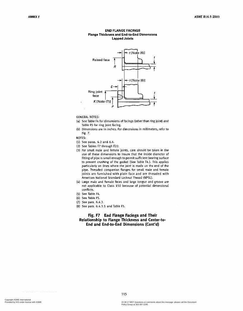
ANNEX F ASME 816.5-2003
END FLANGE FACINGS Flange Thickness and End-to-End Dimensions
Lapped Joints
Raisedface T L i R
I I Ring joint
face
K [Note (7)l P
GENERAL NOTES: (a) See Table F4 for dimensions of facings (other than ring joint) and
Table F5 for ring joint facing. (b) Dimensions are in inches. For dimensions in millimeters, refer to
Fig. 7. NOTES:
See paras. 6.2 and 6.4. See Tables F7 through F22. For small male and female joints, care should be taken in the use of these dimensions to insure that the inside diameter of fitting of pipe is small enough to permit sufficient bearing surface to prevent crushing of the gasket (See Table F4.). This applies particularly on lines where the joint is made on the end of the pipe. Threaded companion flanges for small male and female joints are furnished with plain face and are threaded with American National Standard Locknut Thread (NPSL). Large male and female faces and large tongue and groove are not applicable to Class 150 because of potential dimensional conflicts. See Table F4. See Table F5. See para. 6.4.3. See para. 6.4.3.5 and Table F5.
Fig. F7 End Flange Facings and Their Relationship to Flange Thickness and Center-to-
End and End-to-End Dimensions (Cont’d)
115 Copyright ASME International Provided by IHS under license with ASME
Document provided by IHS Licensee=Qatar Petroleum/5943408001, 09/19/200422:36:17 MDT Questions or comments about this message: please call the DocumentPolicy Group at 303-397-2295.
--```,,`,``,,,,`,,``````,,``,`-`-`,,`,,`,`,,`---
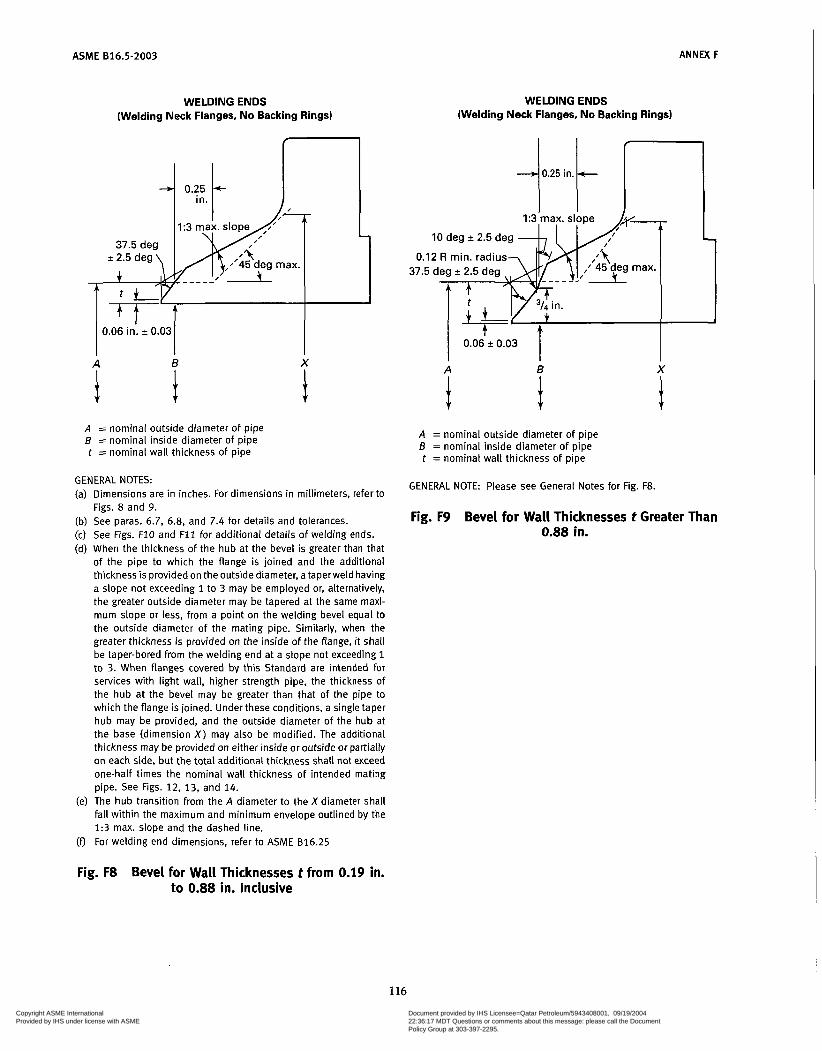
ASME 816.5-2003 ANNEX F
WELDING ENDS (Welding Neck Flanges, No Backing Rings)
37.5 deg f 2.5 deg \ p p 0.06 in. 2 0.03
B
i A = nominal outside diameter of pipe B = nominal inside diameter of pipe t = nominal wall thickness of pipe
X
i
GENERAL NOTES: (a) Dimensions are in inches. For dimensions in millimeters, refer to
Figs. 8 and 9. (b) See paras. 6.7, 6.8, and 7.4 for details and tolerances. (c) See Figs. F10 and F I 1 for additional details of welding ends. (d) When the thickness of the hub at the bevel is greater than that
of the pipe to which the flange is joined and the additional thickness is provided on the outside diameter, a taperweld having a slope not exceeding 1 to 3 may be employed or, alternatively, the greater outside diameter may be tapered at the same maxi- mum slope or less, from a point on the welding bevel equal to the outside diameter of the mating pipe. Similarly, when the greater thickness is provided on the inside of the flange, it shall be taper-bored from the welding end at a slope not exceeding 1 to 3. When flanges covered by this Standard are intended for services with light wall, higher strength pipe, the thickness of the hub at the bevel may be greater than that of the pipe to which the flange is joined. Under these conditions, a single taper hub may be provided, and the outside diameter of the hub at the base (dimension X ) may also be modified. The additional thickness may be provided on either inside or outside or partially on each side, but the total additional thickness shall not exceed one-half times the nominal wall thickness of intended mating pipe. See Figs. 12, 13, and 14.
(e) The hub transition from the A diameter to the X diameter shall fall within the maximum and minimum envelope outlined by the 1:3 max. slope and the dashed line.
(0 For welding end dimensions, refer to ASME 816.25
WELDING ENDS (Welding Neck Flanges, No Backing Rings)
1.3 ilia
10 deg * 2.5 deg
0.12 R min. radius 37.5 deg 2 2.5 deg
0.06+ 0.03 I A B X
i i A = nominal outside diameter of pipe B = nominal inside diameter of pipe t = nominal wall thickness of pipe
GENERAL NOTE: Please see General Notes for Fig. F8.
Fig. F9 Bevel for Wall Thicknesses t Greater Than 0.88 in.
Fig. F8 Bevel for Wall Thicknesses t from 0.19 in. to 0.88 in. Inclusive
116 Copyright ASME International Provided by IHS under license with ASME
Document provided by IHS Licensee=Qatar Petroleum/5943408001, 09/19/200422:36:17 MDT Questions or comments about this message: please call the DocumentPolicy Group at 303-397-2295.
--```,,`,``,,,,`,,``````,,``,`-`-`,,`,,`,`,,`---

ANNEX F
~
ASME 816.5-2003
WELDING ENDS (Welding Neck Flanges)
WELDING ENDS (Welding Neck Flanges)
/ 30deg max. \
I T T I I \ ' '0.12 in. 1 min. radius
0.5 in. min. [Note (1ì1 I I A = nominal outside diameter of welding end, in. B = nominal inside diameter of pipe (-A -2t). in. C = A - 0.031 - 1.75t - 0.010 in. i = nominal wall thickness of pipe
0.031 in. = minus tolerance on outside diameter of pipe to ASTM A 106, etc.
etc.) multiplied by two to convert into terms of diameter
0.010 in. = plus tolerance on diameter C. See para. 7.5.3.
1.75t = 87'Ph of nominal wall (permitted by ASTM A 106,
GENERAL NOTES: (a) Dimensions are in inches. For dimensions in millimeters, refer to
Figs. 10 and 11. (b) See paras. 6.7, 6.8, and 7.5 for details and tolerances. (c) See Figs. F8 and F9 for welding end details of welding neck
flanges. (d) For dimensions, see ASME B16.25. NOTE: (1) 0.5 in. depth based on use of 0.75-in. wide backing ring.
Fig. F i 0 Inside Contour for Use With Rectangular Backing Ring
0.22 in. min.
i A = nominal outside diameter of welding end, in. B = nominal inside diameter of pipe (-A -2t), in. C = A - 0.031 - 1.75t - 0.010 in. i = nominal wall thickness of pipe
0.031 in. = minus tolerance on outside diameter of pipe to ASTM A 106, etc.
etc.) multiplied by two to convert into terms of diameter
0.010 in. = plus tolerance on diameter C. See para. 7.5.3.
1.75t = 87'Ph of nominal wall (permitted by ASTM A 106,
GENERAL NOTES: (a) Dimensions are in inches. For dimensions in millimeters, refer to
Figs. 10 and 11. (b) 0.5 in. depth based on use of 0.75-in. wide backing ring. (c) See Figs 6.7, 6.8, and 7.5 for details and tolerances. (d) See Figs. F8 and F9 for welding end details of welding neck
flanges. (e) For dimensions, see ASME 816.25.
Fig. F l l Inside Contour for Use With Taper Backing Ring
117 Copyright ASME International Provided by IHS under license with ASME
Document provided by IHS Licensee=Qatar Petroleum/5943408001, 09/19/200422:36:17 MDT Questions or comments about this message: please call the DocumentPolicy Group at 303-397-2295.
--```,,`,``,,,,`,,``````,,``,`-`-`,,`,,`,`,,`---
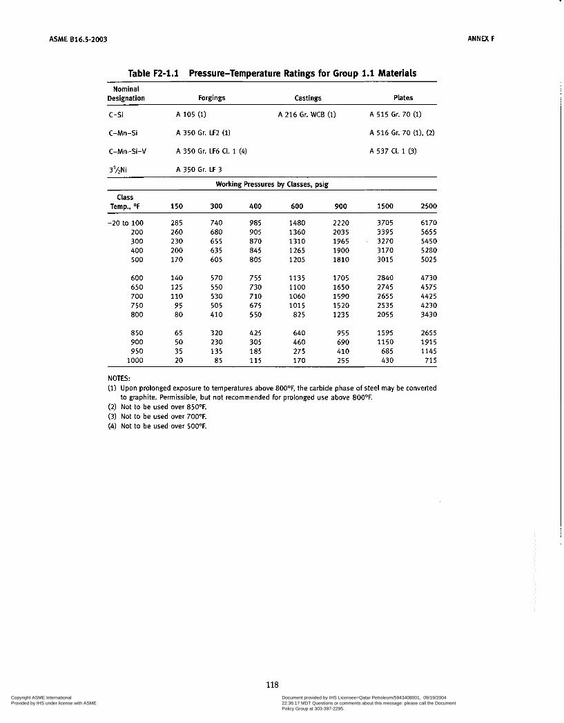
ASME 816.5-2003
Table F2-1.1 Pressure-Temperature Ratings for Group 1.1 Materials
ANNEX F
~
Nominal Designation Forgings Castings Plates
c-si A 105 (1) A 216 Gr. WCB (1) A 515 Gr. 70 (i)
C-Mn-Si A 350 Gr. LF2 (1) A 516 Gr. 70 (l), (2)
C-Mn-Si-V A 350 Gr. LF6 CI. 1 (4) A 537 CI. 1 (3)
3'hNi A 350 Gr. LF 3
Working Pressures by Classes, psig
Temp., OF 150 300 400 600 900 1500 2500
-20 to 100 285 740 985 1480 2220 3705 6170 200 260 680 905 1360 2035 3395 5655 300 230 655 870 1310 1965 3270 5450 400 200 63 5 845 1265 1900 3170 5280 500 170 60 5 805 1205 1810 3015 5025
Class
600 140 570 755 1135 1705 2840 4730 650 125 550 730 1100 1650 2745 4575 700 110 530 710 1060 1590 2655 4425 750 95 505 675 1015 1520 2535 4230 800 80 410 5 50 825 1235 2055 3430
850 65 320 425 640 955 1595 2655 900 50 230 305 460 690 1150 1915 950 35 135 185 275 410 68 5 1145
1000 20 85 1 1 5 170 255 430 71 5
NOTES: (1) Upon prolonged exposure to temperatures above 800°F, the carbide phase of steel may be converted
(2) Not to be used over 85OOF. (3) Not to be used over 700OF. (4) Not to be used over 500OF.
to graphite. Permissible, but not recommended for prolonged use above 800OF.
118 Copyright ASME International Provided by IHS under license with ASME
Document provided by IHS Licensee=Qatar Petroleum/5943408001, 09/19/200422:36:17 MDT Questions or comments about this message: please call the DocumentPolicy Group at 303-397-2295.
--```,,`,``,,,,`,,``````,,``,`-`-`,,`,,`,`,,`---
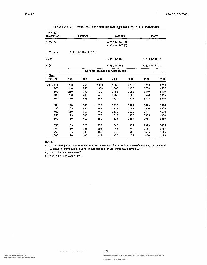
ANNEX F \
ASME 816.5-2003
Table F2-1.2 Pressure-Temperature Ratings for Group 1.2 Materials Nominal
Designation Forgings Castings Plates
C-Mn-Si A 216 Gr. WCC ( i ) A 352 Gr. LCC (2)
C-M-Si-V
2',4Ni A 352 Gr. LC2 A 203 Gr. B (2)
3'/2Ni A 352 Gr. LC3 A 203 Gr. E ( i )
A 350 Gr. LF6 CI. 2 (3)
Working Pressures bv Classes. wig
Class Temp., O F 150 300 400 600 900 1500 2500
-20 to 100 200 300 400 500
600 650 700 750 800
850 900 950
1000
290 260 230 200 170
140 125 110
95 80
65 50 35 20
750 750 730 705 665
605 590 555 505 410
320 225 135 85
1000 1000 970 940 885
805 785 740 675 550
425 295 185 1 1 5
1500 1500 1455 1405 1330
1210 1175 1110 1015 825
640 445 275 170
2250 2250 2185 2110 1995
1815 1765 1665 1520 1235
955 670 410 255
3750 3750 3640 3520 3325
3025 2940 2775 2535 2055
1595 1115
685 430
6250 6250 6070 5865 5540
5040 4905 4630 4230 3430
2655 1855 1145
71 5
NOTES: ( i ) Upon prolonged exposure to temperatures above 8OO0F, the carbide phase of steel may be converted
to graphite. Permissible, but not recommended for prolonged use above 800°F. (2) Not to be used over 65OOF (3) Not to be used over 500°F.
119 Copyright ASME International Provided by IHS under license with ASME
Document provided by IHS Licensee=Qatar Petroleum/5943408001, 09/19/200422:36:17 MDT Questions or comments about this message: please call the DocumentPolicy Group at 303-397-2295.
--```,,`,``,,,,`,,``````,,``,`-`-`,,`,,`,`,,`---
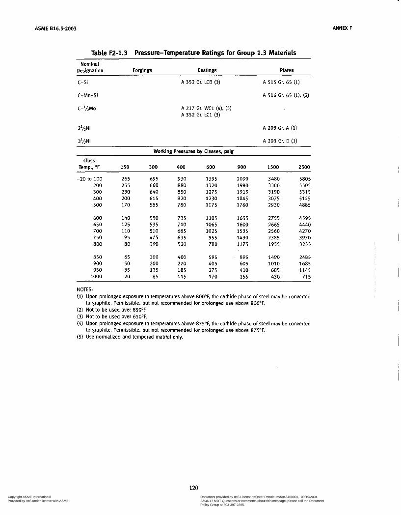
ASME 816.5-2003 ANNEX F
Table F2-1.3 Pressure-Temperature Ratings for Group 1.3 Materials Nominal
Designation Forgings Castings Plates
c-si A 352 Gr. LCB (3) A 515 Gr. 65 (1)
A 516 Gr. 65 (11, (2) C-Mn-Si
C-*LMo A 217 Gr. W C l (4), (5) A 352 Gr. L C l (3)
2%Ni
3'LNi
A 203 Gr. A (1)
A 203 Gr. D ( i )
Working Pressures by Classes, psig
Temp., O F 150 300 400 600 900 1500 2500
-20 to 100 265 695 930 1395 2090 3480 5805 200 255 660 880 1320 1980 3300 5505 300 230 640 850 1275 1915 3190 5315 400 200 61 5 820 1230 1845 3075 5125 500 170 585 780 1175 1760 2930 4885
Class
600 140 550 735 1105 1655 2755 4595 650 125 535 710 1065 1600 2665 4440 700 110 510 685 1025 1535 2560 4270 750 95 475 635 955 1430 2385 3970 800 80 390 520 780 1175 1955 3255
850 65 300 400 595 895 1490 2485 900 50 200 270 40 5 60 5 1010 1685 950 35 135 185 275 410 685 1145
1000 20 85 1 1 5 170 255 430 715
NOTES: (i) Upon prolonged exposure to temperatures above 800°F, the carbide phase of steel may be converted
to graphite. Permissible, but not recommended for prolonged use above 800OF. (2) Not to be used over 85OOF (3) Not to be used over 650OF. (4) Upon prolonged exposure to temperatures above 875OF, the carbide phase of steel may be converted
to graphite. Permissible, but not recommended for prolonged use above 875OF. (5) Use normalized and tempered matrial only.
120 Copyright ASME International Provided by IHS under license with ASME
Document provided by IHS Licensee=Qatar Petroleum/5943408001, 09/19/200422:36:17 MDT Questions or comments about this message: please call the DocumentPolicy Group at 303-397-2295.
--```,,`,``,,,,`,,``````,,``,`-`-`,,`,,`,`,,`---

~~
ANNEX F ASME 816.5-2003
Table F2-1.4 Pressure-Temperature Ratings for Group 1.4 Materials Nominal
Designation Forgings Castings Plates
c-si A 5 1 5 Gr. 60 (1)
C-Mn-Si A 350 Gr. L F l , CI.1 (1) A 516 Gr. 60 (l), (2)
Working Pressures bv Classes, psig
Class Temp., O F 150 300 400 600 900 1500 2500
-20 to 100 200 300 400 500
600 650 700 750 800
850 900 950 1000
235 215 210 200 170
140 125 110
95 80
65 50 3 5 20
61 5 565 545 525 500
475 455 440 430 370
300 170 1 3 5 85
825 755 725 700 670
630 610 590 570 495
400 230 185 -115
1235 1130 1090 1055 1005
945 91 5 885 855 740
595 345 275 170
1850 1695 1635 1580 1505
1420 1370 1325 1285 1110
895 515 410 2 5 5
3085 2830 2725 2635 2510
2365 2285 2210 2140 1850
1490 855 685 430
5145 471 5 4545 4390 4185
3945 3805 3685 3565 3085
2485 1430 1145
715
NOTES: (1) Upon prolonged exposure to temperatures above 8OO0F, the carbide phase of steel may be converted
(2) Not to be used over 85OOF. to graphite. Permissible, but not recommended for prolonged use above 800°F.
121 Copyright ASME International Provided by IHS under license with ASME
Document provided by IHS Licensee=Qatar Petroleum/5943408001, 09/19/200422:36:17 MDT Questions or comments about this message: please call the DocumentPolicy Group at 303-397-2295.
--```,,`,``,,,,`,,``````,,``,`-`-`,,`,,`,`,,`---

ASME 816.5-2003 ANNEX F
Table F2-1.5 Pressure-Temperature Ratings for Group 1.5 Materials Nominal
Designation Forgings Castings Plates
C-%Mo A 182 Gr. F 1 (1) A 204 Gr. A (1) A 204 Gr. B (1)
Working Pressures bv Classes, min Class
Temp., OF 150 300 400 600 900 1500 2500
-20 to 100 200 300 400
500 600 650 700 750
800 850 900 950
1000
265 260 230 200
170 140 1 2 5 110
95
80 65 50 35 20
695 695 685 660
640 605 590 570 530
510 485 450 280 165
930 930 915 885
855 805 785 755 710
675 650 600 375 220
1395 1395 1375 1325
1285 1210 1175 1135 1065
1015 975 900 5 60 330
2090 2090 2060 1985
1925 1815 1765 1705 1595
1 5 2 5 1460 1350
845 495
3480 3480 3435 3310
3210 3025 2940 2840 2660
2540 2435 2245 1405 825
5805 5805 5725 5520
5350 5040 4905 4730 4430
4230 4060 3745 2345 1370
NOTE: (i) Upon prolonged exposure to temperatures above 875OF, the carbide phase of carbon-molybdenum
steel may be converted to graphite. Permissible, but not recommended for prolonged use above 875OF.
122 Copyright ASME International Provided by IHS under license with ASME
Document provided by IHS Licensee=Qatar Petroleum/5943408001, 09/19/200422:36:17 MDT Questions or comments about this message: please call the DocumentPolicy Group at 303-397-2295.
--```,,`,``,,,,`,,``````,,``,`-`-`,,`,,`,`,,`---
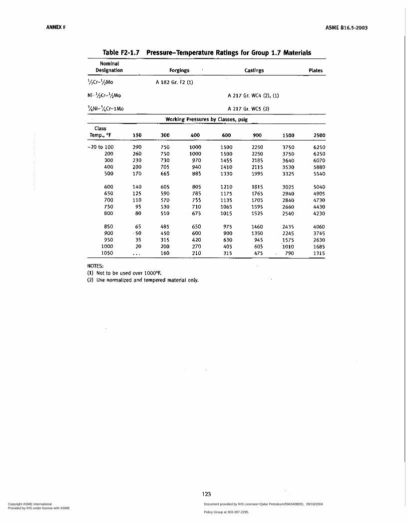
ANNEX F ASME 816.5-2003
Table F2-1.7 Pressure-Temperature Ratings for Group 1.7 Materiais Nominal
Designation Forgings Castings Plates
'LCr-lhMo
Ni-'hCr-'LMo
%Ni-'ACr-lMo
A 182 Gr. F2 (1)
A 217 Gr. WC4 (2), (i)
A 217 Gr. WC5 (2)
Working Pressures by Classes, psig
Temp., O F 150 300 400 600 900 1500 2500
-20 to 100 290 750 1000 1500 2250 3750 6250 200 260 750 1000 1500 2250 3750 6250 300 230 730 970 1455 2185 3640 6070 400 200 705 940 1410 2115 3530 5880 500 170 665 885 1330 1995 3325 5540
Class
600 140 605 805 1210 1815 3025 5040 650 125 590 785 1175 1765 2940 4905 700 110 5 70 755 1135 1705 2840 4730 750 95 530 710 1065 1595 2660 4430 800 80 510 675 1015 1525 2540 4230
850 65 485 650 975 1460 2435 4060 900 50 450 600 900 1350 2245 3745 950 35 315 420 630 945 1575 2630
1000 20 200 270 405 605 1010 1685 1050 ... 160 210 315 475 . 790 1315
NOTES: (i) Not to be used over 1000°F. (2) Use normalized and tempered material only.
123 Copyright ASME International Provided by IHS under license with ASME
Document provided by IHS Licensee=Qatar Petroleum/5943408001, 09/19/200422:36:17 MDT Questions or comments about this message: please call the DocumentPolicy Group at 303-397-2295.
--```,,`,``,,,,`,,``````,,``,`-`-`,,`,,`,`,,`---
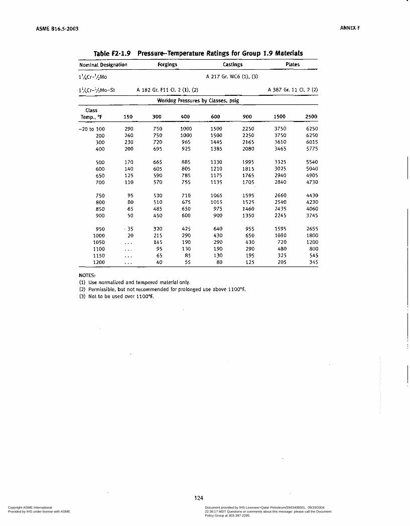
ASME 816.5-2003
Table F2-1.9 Fressure-Temperature Ratings for Group 1.9 Materials
ANNEX F
~~
Nominal Designation Forgings Castings Plates
1 '/Jr-'/!Mo
l'hCr-lhMo-Si
A 217 Gr. WC6 (l), (3)
A 182 Gr. F11 CI. 2 (l), (2) A 387 Gr. 11 CI. 2 (2)
Working Pressures by Classes, psig
Temp., O F 150 300 400 600 900 1500 2500
-20 to 100 290 750 1000 1500 2250 3750 6250 200 260 750 1000 1500 2250 3750 6250 300 230 720 965 1445 2165 3610 601 5 400 200 695 925 1385 2080 3465 5775
Class
500 170 665 885 1330 1995 3325 5540 600 140 605 805 1210 1815 3025 5040 650 125 590 785 1175 1765 2940 4905 700 110 570 755 1135 1705 2840 4730
750 95 530 710 1065 1595 2660 4430 800 80 510 675 1015 1525 2540 4230 850 65 485 650 975 1460 2435 4060 900 50 450 600 900 1350 2245 3745
950 - 35 320 425 640 955 1595 2655 1000 20 21 5 2 90 430 650 1080 1800 1050 . . . 145 190 290 430 720 1200 1100 ... 95 130 190 290 480 800 1150 . . . 65 85 130 195 325 545 1200 ... 40 5 5 80 125 205 345
NOTES: (1) Use normalized and tempered material only. (2) Permissible, but not recommended for prolonged use above 1100OF. (3) Not to be used over 1100OF.
124 Copyright ASME International Provided by IHS under license with ASME
Document provided by IHS Licensee=Qatar Petroleum/5943408001, 09/19/200422:36:17 MDT Questions or comments about this message: please call the DocumentPolicy Group at 303-397-2295.
--```,,`,``,,,,`,,``````,,``,`-`-`,,`,,`,`,,`---
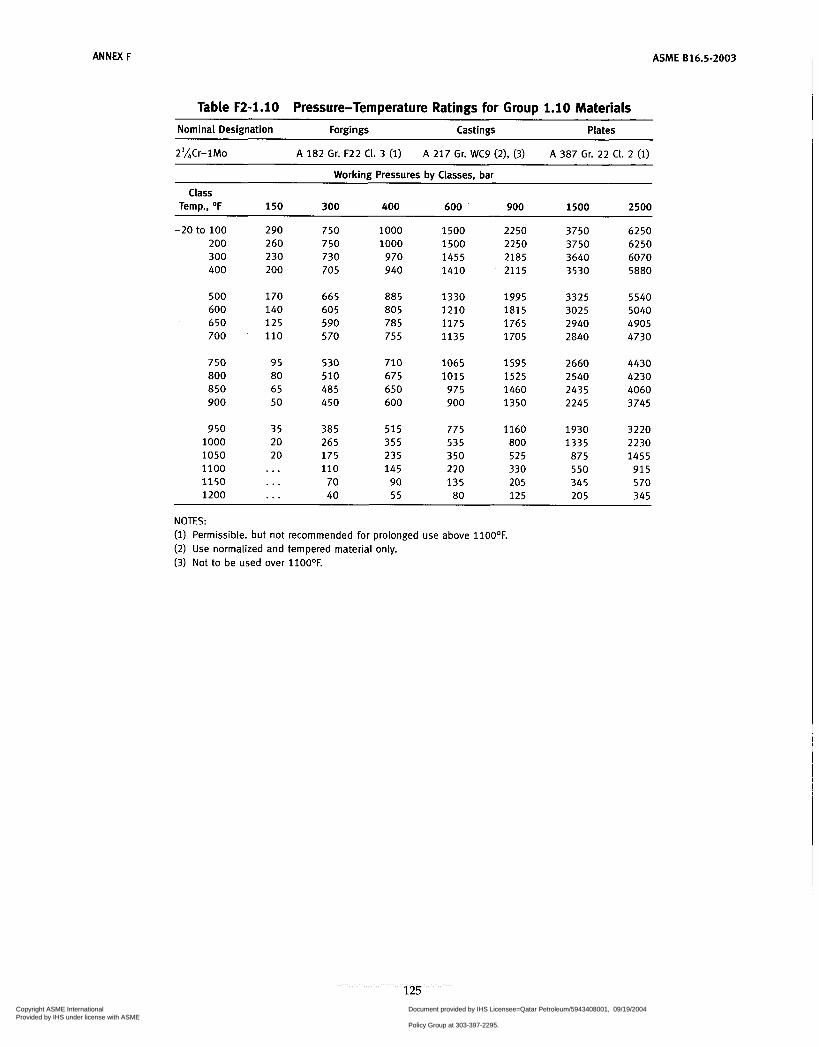
ANNEX F ASME 816.5-2003
Table F2-1.10 Pressure-Temperature Ratings for Group 1.10 Materiais
Nominal Designation Forgings Castings Plates
2'LCr-lMo A 182 Gr. F22 CI. 3 (1) A 217 Gr. WC9 (21, (3) A 387 Gr. 22 CI. 2 (1)
Working Pressures by Classes, bar
Temp., O F 150 300 400 600 900 1500 2500
-20 to 100 290 750 1 O00 1500 2250 3750 6250 200 260 750 1000 1500 2250 3750 6250 300 230 730 970 1455 2185 3640 6070 400 200 705 940 1410 2115 3530 5880
Class
500 170 665 885 1330 1995 3325 5540 600 140 605 805 1210 1815 3025 5040 650 125 590 785 1175 1765 2940 4905 700 ' 110 570 755 1135 1705 2840 4730
750 95 530 710 1065 1595 2660 4430 800 80 510 675 1015 1 5 2 5 2540 4230 850 65 485 650 975 1460 2435 4060 900 50 450 600 900 1350 2245 3745
950 35 385 5 1 5 775 1160 1930 3220 1000 20 265 355 535 800 1335 2230 1050 20 175 235 350 525 875 1455 1100 . . . 110 145 220 330 550 91 5 1150 . . . 70 90 135 205 345 570 1200 ... 40 5 5 80 1 2 5 205 345
NOTES: (1) Permissible. but not recommended for prolonged use above 1100OF. (2) Use normalized and tempered material only. (3) Not to be used over l lOO°F.
125 Copyright ASME International Provided by IHS under license with ASME
Document provided by IHS Licensee=Qatar Petroleum/5943408001, 09/19/200422:36:17 MDT Questions or comments about this message: please call the DocumentPolicy Group at 303-397-2295.
--```,,`,``,,,,`,,``````,,``,`-`-`,,`,,`,`,,`---
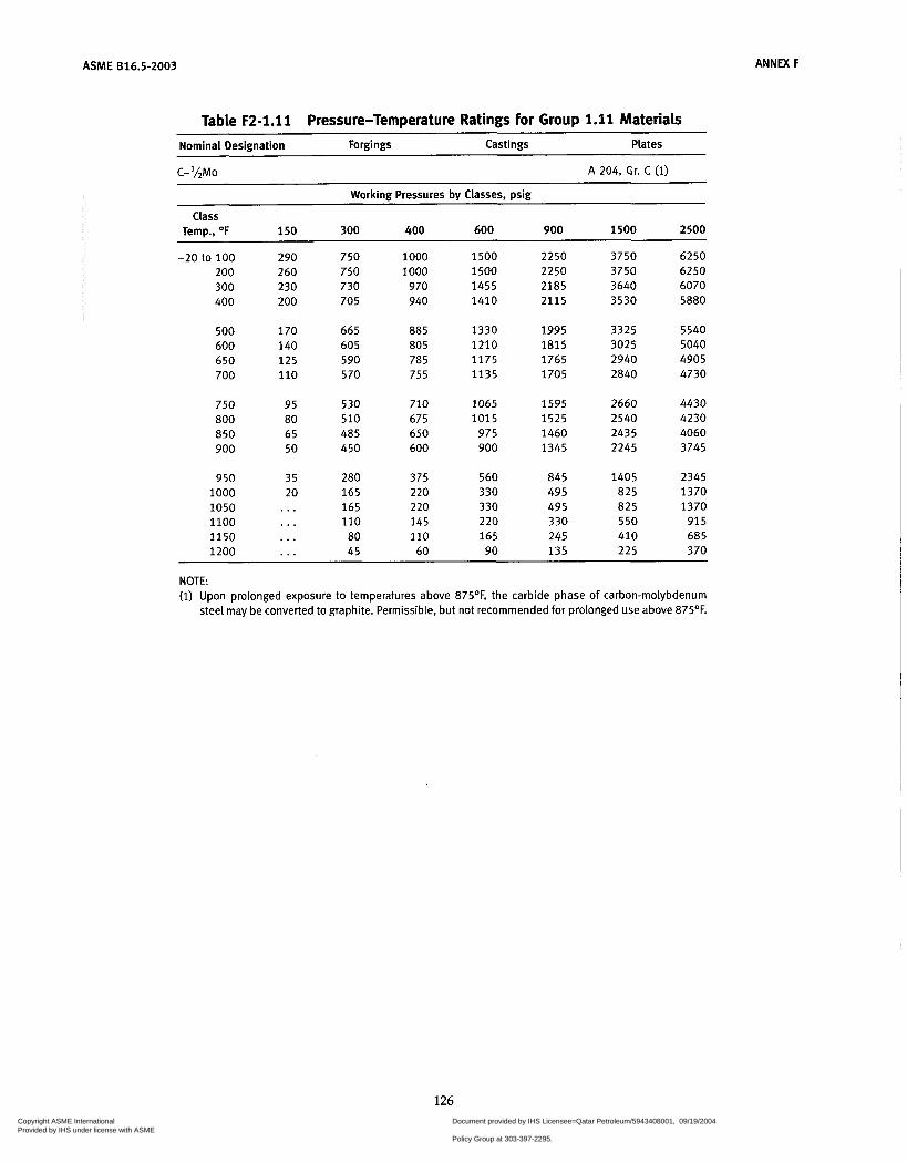
ACME 816.5-2003 ANNEX F
Table F2-1.11 Pressure-Temperature Ratings for Group 1.11 Materials Nominal Designation Forgings Castings Plates
C-lAMo A 204, Gr. C (1)
Working Pressures by Classes, psig
Temp., O F 150 300 400 600 900 1500 2500
-20 to 100 2 90 750 1000 1500 2250 3750 6250 200 260 750 1 O00 1500 2250 3750 6250 300 230 730 970 1455 2185 3640 6070
Class
400 200 705 940 1410 2115 3530 5880
500 170 665 a85 1330 1995 3325 5540 600 140 605 ao5 1210 ia15 3025 5040 650 125 590 785 1175 1765 2940 4905 700 110 570 755 1135 1705 2840 4730
750 95 530 710 1065 1595 2660 4430 ao0 ao 510 675 1015 1525 2540 4230 a50 65 485 650 975 1460 2435 4060 900 50 450 600 900 1345 2245 3745
950 35 280 375 560 a45 1405 2345 1000 20 165 220 330 495 825 1370 1050 ... 165 220 330 495 a25 1370 1100 ... 110 145 220 330 550 915 1150 ... 80 110 165 245 410 685 1200 . . . 45 60 90 135 225 370
NOTE: (i) Upon prolonged exposure to temperatures above 875'F. the carbide phase of carbon-molybdenum
steel may be converted to graphite. Permissible, but not recommended for prolonged use above 875OF.
126 Copyright ASME International Provided by IHS under license with ASME
Document provided by IHS Licensee=Qatar Petroleum/5943408001, 09/19/200422:36:17 MDT Questions or comments about this message: please call the DocumentPolicy Group at 303-397-2295.
--```,,`,``,,,,`,,``````,,``,`-`-`,,`,,`,`,,`---

ANNEX F ASME B16.5-2003
Table F2-1.13 Pressure-Temperature Ratings for Group 1.13 Materials Nominal Designation Forgings Castings Plates
5Cr-'hMo A 182 Gr. F5a A 217 Gr. C5 (i) . . . Workina Pressures bv Classes, Dsig
Class Temp., OF 150 300 400 600 900 1500 2500
-20 to 100 200 300 400 500 600
650 700 750 800 850 900
950 1000 1050 1100 1150 1200
290 260 230 200 170 140
125 110
95 80 65 50
35 20
. . .
. . .
. . .
. . .
750 750 730 705 665 605
590 570 530 510 485 375
275 200 145 100 60 35
1000 1000 970 940 885 805
785 755 710 675 650 500
365 265 190 135 80 45
1500 1500 1455 1410 1330 1210
1175 1135 1065 1015
975 745
550 400 290 200 1 2 5
70
2250 2250 2185 2115 1995 1815
1765 1705 1595 1525 1460 1120
82 5 595 430 300 185 105
3750 3750 3640 3530 3325 3025
2940 2840 2660 2540 2435 1870
1370 995 720 495 310 170
6250 6250 6070 5880 5540 5040
4905 4730 4430 4230 4060 3115
2285 1655 1200 830 515 285
NOTE: (1) Use normalized and tempered material only.
127
Copyright ASME International Provided by IHS under license with ASME
Document provided by IHS Licensee=Qatar Petroleum/5943408001, 09/19/200422:36:17 MDT Questions or comments about this message: please call the DocumentPolicy Group at 303-397-2295.
--```,,`,``,,,,`,,``````,,``,`-`-`,,`,,`,`,,`---
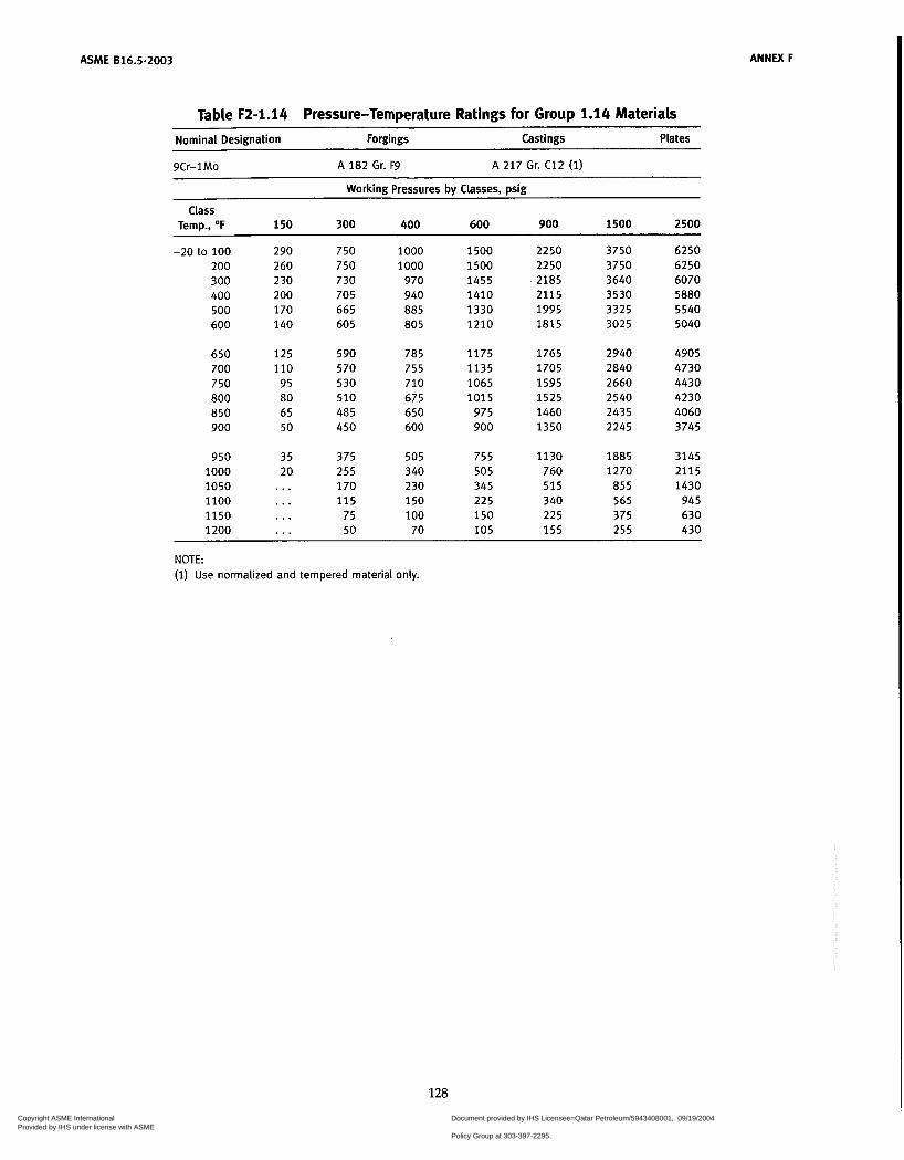
ASME 816.5-2003 ANNEX F
Table F2-1.14 Pressure-Temperature Ratings for Group 1.14 Materials
Nominal Designation Forgings Castings Plates
9Cr-1Mo A 182 Gr. F9 A 217 Gr. C12 (i)
Working Pressures bv Classes. psig
Class Temp., O F 150 300 400 600 900 1500 2500
-20 to 100 200 300 400 500 600
290 260 230 200 170 140
750 750 730 705 665 605
1000 1000
970 940 885 805
1500 1500 1455 1410 1330 1210
2250 2250 2185 2115 1995 1815
3750 3750 3640 3530 3325 3025
6250 6250 6070 5880 5540 5040
650 700 750 800 850 900
950 1000 1050 1100 1150 1200
1 2 5 110
95 80 65 50
35 20 ... ... ... ...
590 570 530 510 485 450
375 255 170 1 1 5
75 50
785 755 710 675 650 600
505 340 230 150 1 O0
70
1175 1135 1065 1015
975 900
755 505 345 225 150 105
1765 1705 1595 1525 1460 1350
1130 760 515 340 225 1 5 5
2940 2840 2660 2540 2435 2245
1885 1270
855 565 375 255
4905 4730 4430 4230 4060 3745
3145 2115 1430
945 630 430
~
NOTE: (1) Use normalized and tempered material only.
128
Copyright ASME International Provided by IHS under license with ASME
Document provided by IHS Licensee=Qatar Petroleum/5943408001, 09/19/200422:36:17 MDT Questions or comments about this message: please call the DocumentPolicy Group at 303-397-2295.
--```,,`,``,,,,`,,``````,,``,`-`-`,,`,,`,`,,`---
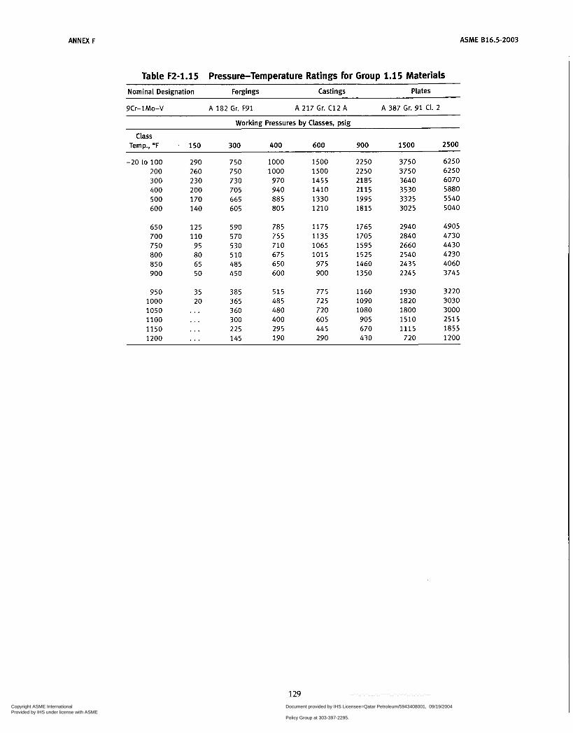
ANNEX F ASME 816.5-2003
Table F2-1.15 Pressure-Temperature Ratings for Group 1.1 5 Materials Nominal Designation Forgings Castings Plates
9Cr-1Mo-V A 182 Gr. F91 A 217 Gr. C12 A A 387 Gr. 91 CI. 2
Working Pressures by Classes, psig
Temp., OF 150 300 400 600 900 1500 2500
-20 to 100 290 750 1000 1500 2250 3750 6250 200 260 750 1000 1500 2250 3750 6250 300 230 730 970 1455 2185 3640 6070 400 200 705 940 1410 2115 3530 5880 500 170 665 885 1330 1995 3325 5540 600 140 605 805 1210 1815 3025 5040
Class
650 1 2 5 590 785 1175 1765 2940 4905 700 110 570 755 1135 1705 2840 4730 750 95 530 710 1065 1595 2660 4430 800 80 510 675 1015 1525 2540 4230 850 65 485 650 975 1460 2435 4060 900 50 450 600 900 1350 2245 3745
950 35 385 515 775 1160 1930 3220 1000 20 365 485 725 1090 1820 3030 1050 . . . 360 480 720 1080 1800 3000 1100 ... 300 400 605 905 1510 2515 1150 ... 225 295 445 670 1 1 1 5 1855 1200 . . . 145 190 290 430 720 1200
129 Copyright ASME International Provided by IHS under license with ASME
Document provided by IHS Licensee=Qatar Petroleum/5943408001, 09/19/200422:36:17 MDT Questions or comments about this message: please call the DocumentPolicy Group at 303-397-2295.
--```,,`,``,,,,`,,``````,,``,`-`-`,,`,,`,`,,`---
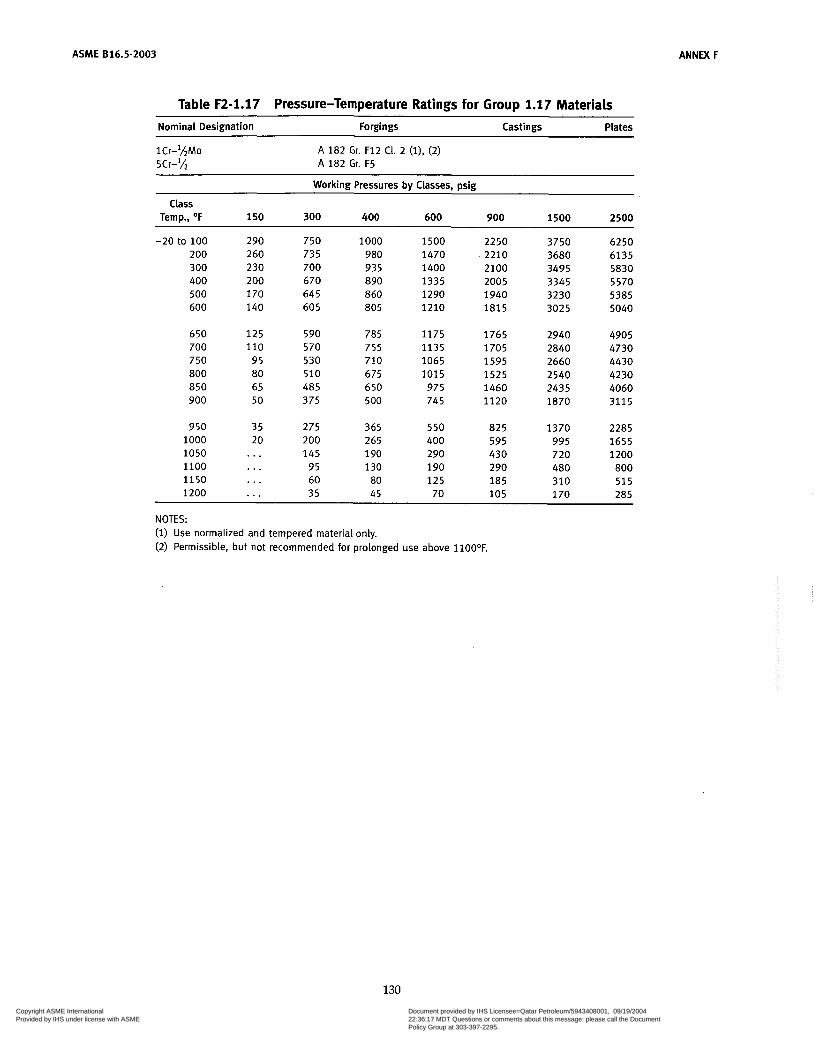
ASME 816.5-2003 ANNEX F
Table F2-1.17 Pressure-Temperature Ratings for Group 1.17 Materials
Nominal Designation Forgings Castings Plates ~~
A 182 Gr. F12 CI. 2 (i), (2) A 182 Gr. F5
Working Pressures by Classes, psig
Temp., O F 150 300 400 600 900 1500 2500
-20 to 100 290 750 1000 1500 2250 3750 6250 200 260 735 980 1470 2210 3680 6135 300 230 700 935 1400 2100 3495 5830 400 200 670 890 1335 2005 3345 5570 500 170 645 860 1290 1940 3230 5385 600 140 605 805 1210 i a 1 5 3025 5040
Class
650 125 590 785 1175 1765 2940 4905 700 110 570 755 1135 1705 2840 4730 750 95 530 710 1065 1595 2660 4430 800 80 510 675 1015 1525 2540 4230 850 65 485 650 975 1460 2435 4060 900 50 375 500 745 1120 1870 3115
950 35 275 365 550 825 1370 2285 1000 20 200 265 400 595 995 1655 1050 . . . 145 190 290 430 720 1200 1100 ... 95 130 190 290 480 a00 1150 . . . 60 ao 125 i a 5 310 515 1200 . . . 35 45 70 105 170 285
NOTES: (1) Use normalized and tempered material only. (2) Permissible, but not recommended for prolonged use above l iOO°F.
130 Copyright ASME International Provided by IHS under license with ASME
Document provided by IHS Licensee=Qatar Petroleum/5943408001, 09/19/200422:36:17 MDT Questions or comments about this message: please call the DocumentPolicy Group at 303-397-2295.
--```,,`,``,,,,`,,``````,,``,`-`-`,,`,,`,`,,`---
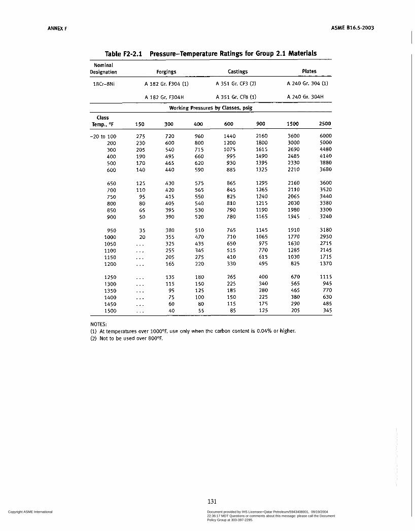
ANNEX F ASME 816.5-2003
Table F2-2.1 Pressure-Temperature Ratings for Group 2.1 Materials
Nominal Designation Forgings Castings Plates
18Cr-8Ni A 182 Gr. F304 (1) A 3 5 1 Gr. CF3 (2) A 240 Gr. 304 (1)
A 182 Gr. F304H A 3 5 1 Gr. CF8 (1) A 240 Gr. 304H
Working Pressures by Classes, psig
Temp., O F 150 300 400 600 900 1500 2500 Class
-20 to 100 200 300 400 500 600
650 700 750 800 850 900
950 1000 1050 1100 1150 1200
1250 1300 1350 1400 1450 1500
275 230 205 190 170 140
125 110 95 80 65 50
35 20
. . .
. . .
. . .
. . .
. . .
...
. . .
. . .
. . .
. . .
720 600 540 495 465 440
430 420 41 5 405 395 390
380 355 325 255 205 165
135 1 1 5
95 75 60 40
960 800 715 660 620 590
575 565 550 540 530 520
510 470 435 345 275 220
180 150 125 100 80 55
1440 1200 1075
995 930 885
865 845 825 810 790 780
765 710 650 515 410 330
265 225 185 150 115 85
2160 1800 1615 1490 1395 1325
1295 1265 1240 1215 1190 1165
1145 1065 975 770 61 5 49 5
400 340 280 225 175 125
3600 3000 2690 2485 2330 2210
2160 2110 2065 2030 1980 1945
1910 1770 1630 1285 1030
82 5
670 565 465 380 290 205
6000 5000 4480 4140 3880 3680
3600 3520 3440 3380 3300 3240
3180 2950 2715 2145 1715 1370
1115 945 770 630 485 345
NOTES: (1) At temperatures over 1000°F, use only when the carbon content is 0.04% or higher. (2) Not to be used over 800OF.
131 Copyright ASME International Provided by IHS under license with ASME
Document provided by IHS Licensee=Qatar Petroleum/5943408001, 09/19/200422:36:17 MDT Questions or comments about this message: please call the DocumentPolicy Group at 303-397-2295.
--```,,`,``,,,,`,,``````,,``,`-`-`,,`,,`,`,,`---
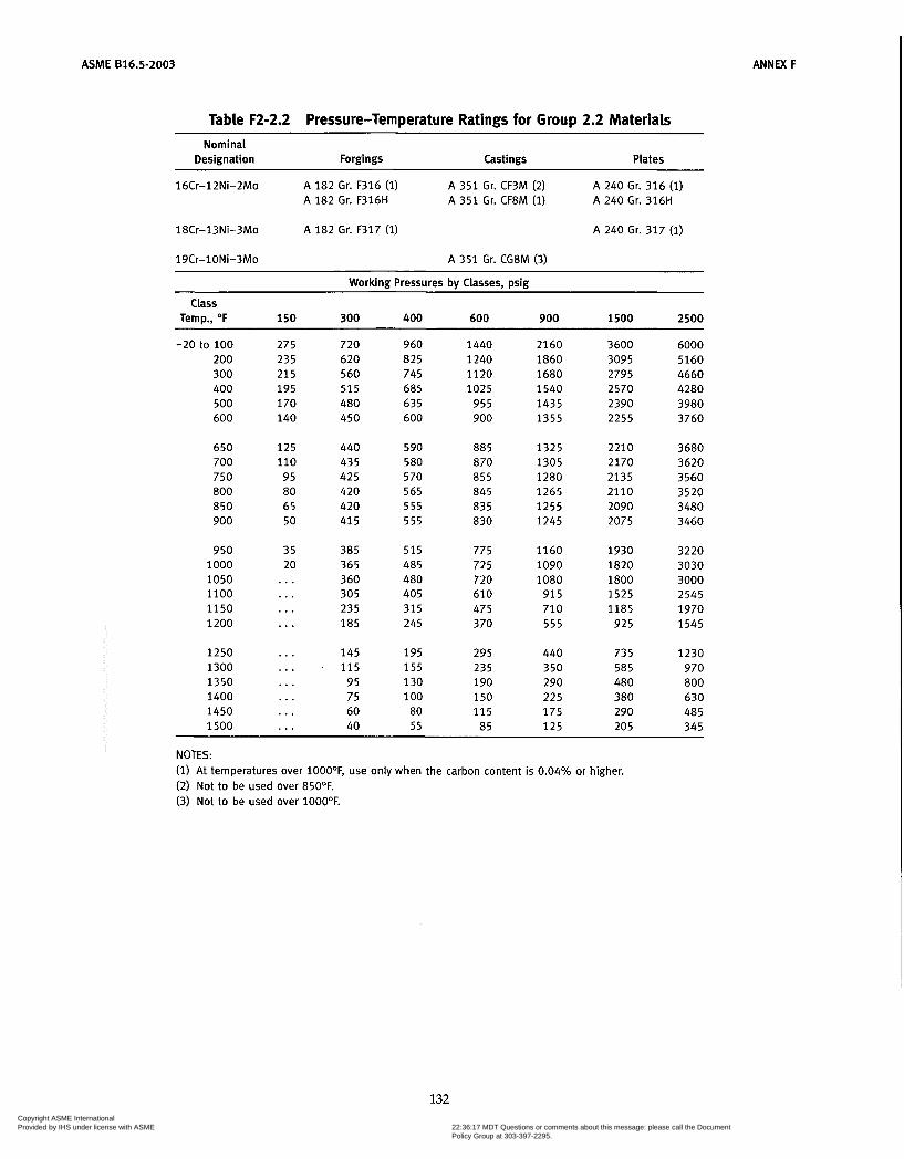
ASME 816.5-2003 ANNEX F
Table F2-2.2 Pressure-Temperature Ratings for Group 2.2 Materials Nominal
Designation Forgings Castings Plates
16Cr-12Ni-2Mo A 182 Gr. F316 ( i) A 182 Gr. F316H
A 182 Gr. F317 (i)
A 351 Gr. CF3M (2) A 351 Gr. CF8M (1)
A 240 Gr. 316 (1) A 240 Gr. 316H
A 240 Gr. 317 (1) lûCr-13Ni-3Mo
19Cr-lONi-3Mo A 3 5 1 Gr. CG8M (3)
Working Pressures bv Classes. min Class
Temp., O F 150 300 400 600 900 1500 2500
-20 to 100 200 300 400 500 600
650 700 750 800 850 900
950 1000 1050 1100 1150 1200
1250 1300 1350 1400 1450 1500
275 235 215 195 170 140
125 110 95 80 65 50
35 20 ... . . . . . . . . .
. . .
. . .
. . .
. . .
. . .
. . .
720 620 560 515 480 450
440 435 425 420 420 41 5
385 365 360 305 235 185
145 1 1 5
95 75 60 40
960 825 745 685 635 600
590 580 570 565 555 555
515 485 480 405 315 245
195 1 5 5 130 1 O0
80 5 5
1440 1240 1120 1025
955 900
885 870 855 845 835 830
775 725 720 610 475 370
295 235 190 150 115 85
2160 1860 1680 1540 1435 1355
1325 1305 1280 1265 1 2 5 5 1245
1160 1090 1080 91 5 710 555
440 350 290 225 175 1 2 5
3600 3095 2795 2570 2390 2255
2210 2170 2135 2110 2090 2075
1930 1820 1800 1525 1185
925
735 585 480 380 290 205
6000 5160 4660 4280 3980 3760
3680 3620 3560 3520 3480 3460
3220 3030 3000 2545 1970 1545
1230 970 800 630 485 345
NOTES: (i) At temperatures over 1000°F, use only when the carbon content is 0.04% or higher. (2) Not to be used over 85OOF. (3) Not to be used over 1000°F.
132 Copyright ASME International Provided by IHS under license with ASME
Document provided by IHS Licensee=Qatar Petroleum/5943408001, 09/19/200422:36:17 MDT Questions or comments about this message: please call the DocumentPolicy Group at 303-397-2295.
--```,,`,``,,,,`,,``````,,``,`-`-`,,`,,`,`,,`---

ANNEX F ASME B16.5-2003
Table F2-2.3 Pressure-Temperature Ratings For Group 2.3 Materials Nominal
Designation Forgings Cast in gs Plates
16Cr-12Ni-ZMo A 182 Gr. F316L A 240 Gr. 316L 18Cr-8Ni A 182 Gr. F304L (i) A 240 Gr. 304L (i)
Workinrr Pressures bv Classes, min Class
Temp., O F 150 300 400 600 900 1500 2500
-20 to 100 230 600 800 1200 1800 3000 5000 200 195 510 680 1020 1535 2555 4260 300 175 455 610 910 1370 2280 3800 400 160 420 560 840 1260 2100 3500 500 150 395 525 78 5 1180 1970 3280
600 140 370 495 74 5 1115 1860 3100 650 125 365 485 730 3095 1825 3040 700 110 360 480 720 1080 1800 3000 750 95 355 470 705 1060 1765 2940 800 80 345 460 690 1035 1730 2880 850 65 340 450 675 1015 1690 2820
NOTE: (1) Not to be used over 80OOF.
133
Copyright ASME International Provided by IHS under license with ASME
Document provided by IHS Licensee=Qatar Petroleum/5943408001, 09/19/200422:36:17 MDT Questions or comments about this message: please call the DocumentPolicy Group at 303-397-2295.
--```,,`,``,,,,`,,``````,,``,`-`-`,,`,,`,`,,`---

ASME 816.5-2003 ANNEX F
Table F2-2.4 Pressure-Temperature Ratings for Group 2.4 Materials ~~ ~
Nominal Designation Forgings Castings Plates
~~ ~~ ~~
18Cr-1ONi-Ti A 182 Gr. F321 ( i ) . . . A 240 Gr. 321 (1) A 182 Gr. F321H (2) . . . A 240 Gr. 321H (2)
Working Pressures by Classes, psig
Class Temp., O F 150 300 400 600 900 1500 2500
-20 to 100 200 300 400 500 600
650 700 750 800 850 900
950 1000 1050 1100 1150 1200
1250 1300 1350 1400 1450 1500
275 250 230 200 170 140
125 110
95 80 65 50
35 20
. . .
. . .
. . .
. . .
. . .
. . .
. . .
. . .
. . .
. . .
720 650 595 550 5 1 5 485
475 465 460 450 445 440
385 365 360 310 235 185
140 110 85 65 50 40
960 865 795 735 690 650
635 620 610 600 595 590
5 1 5 485 480 415 315 245
185 145 115
85 70 50
1440 1295 1190 1105 1030
975
950 930 915 900 895 885
775 725 720 625 475 370
280 220 170 130 105
75
2160 1945 1785 1655 1550 1460
1425 1395 1375 1 3 5 5 1340 1325
1160 1090 1080
935 710 5 5 5
420 330 255 195 155 115
3600 3240 2975 2760 2580 2435
2375 2330 2290 2255 2230 2210
1930 1820 1800 1560 1185 925
705 550 430 325 2 5 5 190
6000 5400 4960 4600 4300 4060
3960 3880 3820 3760 3720 3680
3220 3030 3000 2600 1970 1545
1170 91 5 715 545 430 315
~ ~~
NOTES: (1) Not to be used over 1000°F. (2) At temperatures over 1000°F, use only if the material is heat treated by heating to a minimum
temperature of 20OOOF.
134
Copyright ASME International Provided by IHS under license with ASME
Document provided by IHS Licensee=Qatar Petroleum/5943408001, 09/19/200422:36:17 MDT Questions or comments about this message: please call the DocumentPolicy Group at 303-397-2295.
--```,,`,``,,,,`,,``````,,``,`-`-`,,`,,`,`,,`---

ANNEX F ASME 816.5-2003
Table F2-2.5 Pressure-Temperature Ratings for Group 2.5 Materials Nominal Designation Forgings Cast in gs Plates
1aCr-1ONi-Cb A 182 Gr. F347 ( i) A 182 Gr. F347H (2) A 182 Gr. ~ 3 4 8 (1) A 182 Gr. F348H (2)
A 240 Gr. 347 (1) A 240 Gr. 347H (2) A 240 Gr. 348 (i) A 240 Gr. 348H (2)
Working Pressures bv Classes, Dsk
Class Temp., O F 150 300 400 600 900 1500 2500
-20 to 100 275 200 255 300 230 400 200 500 170 600 140
650 125 700 110 750 95
a50 65 900 50
ao0 ao
950 35 1000 20 1050 . . . 1100 . . . 1150 . . . 1200 . . .
1250 . . . 1300 . . . 1350 . . . 1400 . . . 1450 . . . 1500 ,..
720 660 61 5 575 540 5 1 5
505 495 490 485 485
385
450
365 360 325 275 205
i ao 140 105
75 60 40
960 aaç a20 770 725 690
675 660 655 650 645 600
5 1 5 485 480 430 365 275
245
140 100
55
i a5
ao
1440 1325 1235 1150
1030
1015 995
97 5 970 900
775 725 720 645 550 410
365 275 205 150 115
1085
985
a5
2160 1985
1730 1625 1550
1520 1490 1475 1460 1455 1350
1160 1090
965
620
545 410 310 225 175 125
i a 5 0
ioao
a25
3600 3310 3085 2880
2580 2710
2530 2485 2460 2435 2425 2245
1930 ia20 iaoo 1610 1370 1030
910
5 1 5
290 205
685
380
6000 5520 5140
4520 4300
4220 4140 4100 4060 4040 3745
3220 3030 3000
4800
2685 2285 1715
1515 1145 860 630
345 485
~
NOTES: (1) Not to be used over 1000°F. (2) For temperatures over 1000°F use only if the material is heat treated by heating to a
temperature of 2000OF. minimum
135 Copyright ASME International Provided by IHS under license with ASME
Document provided by IHS Licensee=Qatar Petroleum/5943408001, 09/19/200422:36:17 MDT Questions or comments about this message: please call the DocumentPolicy Group at 303-397-2295.
--```,,`,``,,,,`,,``````,,``,`-`-`,,`,,`,`,,`---
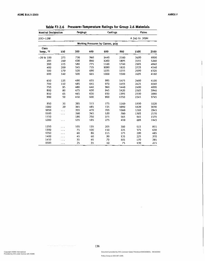
ASME 816.5-2003 ANNEX F
Table F2-2.6 Pressure-Temperature Ratings for Group 2.6 Materials -
Nominal Designation Forgings Castings Plates
23Cr-12Ni A 240 Gr. 309H
Working Pressures bv Classes. psir! -
Class Temp., O F 150 300 400 600 900 1500 2500
275 240 225 200 170 140
720 630 580 545 520 500
960 840 775 725 690 665
1440 1260 1160 1090 1035 1000
2160 1895 1740 1635 1555 1500
3600 3155 2905 2725 2590 2495
6000 5260 4840 4540 4320 4160
-20 to 100 200 300 400 500 600
650 700 750 800 850 900
125 110
95 80 65 50
490 485 480 475 465 450
655 645 640 630 620 600
985 970 960 945 930 900
1475 1455 1440 1420 1395 1350
2460 2425 2400 2365 2330 2245
4100 4040 4000 3940 3880 3745
950 1000 1050 1100 1150 1200
35 20
385 365 355 2 60 190 135
5 1 5 485 470 345 250 185
775 725 705 520 375 275
1160 1090 1060 780 565 410
1930 1820 1765 1305 945 685
3220 3030 2945 2170 1570 1145
. . .
. . .
1250 1300 1350 1400 1450 1500
105 75 60 45 35 25
135 100
80 60 45 35
205 150 1 1 5 90 70 50
310 225 175 135 105
75
515 375 290 225 170 130
855 630 485 370 285 215
...
...
. . .
...
...
136
Copyright ASME International Provided by IHS under license with ASME
Document provided by IHS Licensee=Qatar Petroleum/5943408001, 09/19/200422:36:17 MDT Questions or comments about this message: please call the DocumentPolicy Group at 303-397-2295.
--```,,`,``,,,,`,,``````,,``,`-`-`,,`,,`,`,,`---

ANNEX F ASME 816.5-2003
Table F2-2.7 Pressure-Temperature Ratings for Group 2.7 Materials Nominal
Designation Forgings Castings Plates
25Cr-20Ni A 182 Gr. F310 (i), (2) A 240 Gr. 310H
Working Pressures bv Classes, psig
Class Temp., O F 150 300 400 600 900 1500 2500
-20 to 100 200 300 400 500 600
650 700 750 800 850 900
950 1000 1050 1100 1150 1200
1250 1300 1350 1400 1450 1500
275 245 225 200 170 140
125 110
95 80 65 50
35 20
. . .
. . .
. . .
. . .
. . .
. . .
. . .
. . .
. . .
. . .
720 635 580 540 5 1 5 495
485 480 470 465 460 450
385 365 355 2 60 190 135
105 75 60 45 35 25
960 850 775 725 685 660
64 5 63 5 625 620 610 600
515 485 470 345 250 185
135 100 80 60 45 35
1440 1270 1160 1085 1025
990
970 955 940 930 91 5 900
775 725 705 520 375 275
205 150 115
90 65 50
2160 1910 1740 1625 1540 1485
1455 1435 1410 1395 1375 1350
1160 1090 1060
780 565 410
310 2 2 5 175 135 1 O0 75
3600 3180 2905 2710 2570 2470
2425 2390 2350 2330 2290 2245
1930 1820 1765 1305 945 685
5 1 5 375 290 225 165 130
6000 5300 4840 4520 4280 4120
4040 3980 3920 3880 3820 3745
3220 3030 2945 2170 1570 1145
855 630 485 370 275 2 1 5
NOTES: (1) At temperatures over 1000°F, use only when the carbon content is 0.04% or higher. (2) Service temperatures of 1O5O0F and above should be used only when assurance is provided that
grain size is not finer than ASTM 6.
137
Copyright ASME International Provided by IHS under license with ASME
Document provided by IHS Licensee=Qatar Petroleum/5943408001, 09/19/200422:36:17 MDT Questions or comments about this message: please call the DocumentPolicy Group at 303-397-2295.
--```,,`,``,,,,`,,``````,,``,`-`-`,,`,,`,`,,`---

ANNEX F ASME B16.5-2003
Table F2-2.8 Pressure-Temperature Ratings for Group 2.8 Materials
Nominal Designation Forgings Castings Plates
20Cr-18Ni-6Mo A 182 Gr. F44 A 351 Gr. CK3MCuN A 240 Gr. S31254
22Cr-5Ni-3Mo-N A 182 Gr. F51 (1) A 240 Gr. 531803 (i)
25Cr-7Ni-4Mo-N
24Cr-10Ni-4Mo-V
A 182 Gr. F53 (1) A 240 Gr. S32750 (1)
A 351 Gr. CEBMN (1)
25Cr-5Ni-ZMo-3Cu A 351 Gr. CD4MCu (i)
25Cr-7Ni-3.5Mo-W-Cb
25Cr-7Ni-3.5Mo-N-Cu-W A 182 Gr. F55 (1)
A 351 Gr. CD3MWCuN (1)
A 240 Gr. 532760 (1)
Working Pressures by Classes, psig
Temp., OF 150 300 400 600 900 1500 2500
100 290 750 1 O00 1500 2250 3750 6250 200 260 745 990 1490 2230 3720 6200 300 230 665 890 1335 2000 3335 5560
400 200 615 820 1230 1845 3070 5120 500 170 580 775 1160 1740 2905 4840 600 140 555 740 1115 1670 2785 4640
Class
650 125 545 730 1095 1640 2735 4560 700 110 540 725 1085 1625 2710 4520 750 95 530 710 1065 1595 2660 4430
~
NOTE: (i) This steel may become brittle after service at moderately elevated temperatures. Not to be used
over 600OF.
138
Copyright ASME International Provided by IHS under license with ASME
Document provided by IHS Licensee=Qatar Petroleum/5943408001, 09/19/200422:36:17 MDT Questions or comments about this message: please call the DocumentPolicy Group at 303-397-2295.
--```,,`,``,,,,`,,``````,,``,`-`-`,,`,,`,`,,`---
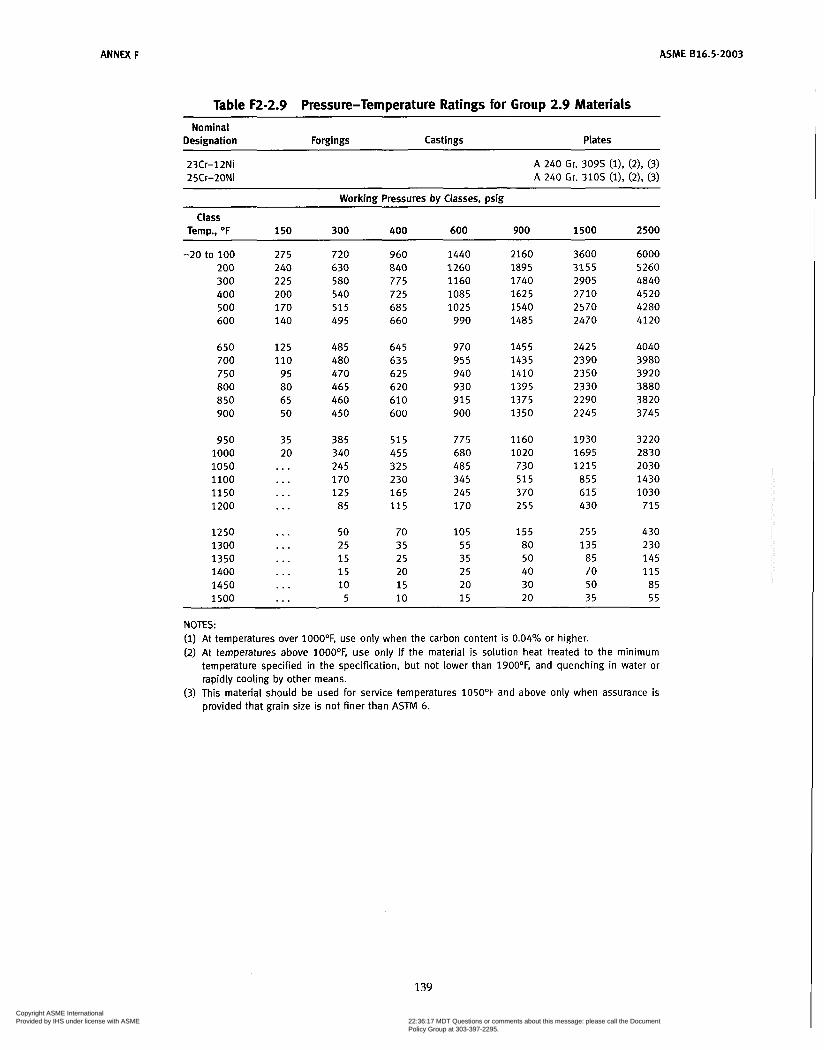
ANNEX F ASME 016.5-2003
Table F2-2.9 Pressure-Temperature Ratings for Group 2.9 Materials
Nominal Designation Forgings Cast i ngs Plates
23Cr-12Ni 25Cr-20Ni
A 240 Gr. 3095 (i), (2), (3) A 240 Gr. 3105 (l), (2), (3)
Working Pressures by Classes, psig
Temp., O F 150 300 400 600 900 1500 2500
-20 to 100 275 720 960 1440 2160 3600 6000 200 240 630 840 1260 1895 3155 5260 300 225 580 775 1160 1740 2905 4840 400 200 540 725 1085 1625 2710 4520 500 170 515 685 1025 1540 2570 4280 600 140 495 660 990 1485 2470 4120
Class
650 125 485 645 970 1455 2425 4040 700 110 480 635 955 1435 2390 3980 750 95 470 625 940 1410 2350 3920 800 ao 465 620 930 1395 2330 3880 850 65 460 610 91 5 1375 2290 3820 900 50 450 600 900 1350 2245 3745
950 35 385 5 1 5 775 1160 1930 3220 1000 20 340 455 680 1020 1695 2830 1050 ... 245 325 485 730 1215 2030 1100 ... 170 230 345 5 1 5 855 1430 1150 ... 125 165 245 370 615 1030 1200 ... 85 115 170 2 5 5 430 71 5
1250 ,,. 50 70 105 155 255 430 1300 . . . 25 35 5 5 80 135 230 1350 . . . 1 5 25 35 50 85 145 1400 . . . 1 5 20 25 40 70 115 1450 . . . 10 1 5 20 30 50 85 1500 ... 5 10 1 5 20 35 5 5
NOTES: (1) At temperatures over 1000°F, use only when the carbon content is 0.04% or higher. (2) At temperatures above 1000°F, use only i f the material is solution heat treated to the minimum
temperature specified in the specification, but not lower than 1900°F, and quenching in water or rapidly cooling by other means.
(3) This material should be used for service temperatures 105OOF and above only when assurance is provided that grain size is not finer than ASTM 6.
139
Copyright ASME International Provided by IHS under license with ASME
Document provided by IHS Licensee=Qatar Petroleum/5943408001, 09/19/200422:36:17 MDT Questions or comments about this message: please call the DocumentPolicy Group at 303-397-2295.
--```,,`,``,,,,`,,``````,,``,`-`-`,,`,,`,`,,`---

ASME 816.5-2003
Table F2-2.10 Pressure-Temperature Ratings for Group 2.10 Materials
ANNEX F
Nominal Designation Forgings Cast in gs Plates
2 5Cr-12Ni A 351 Gr. CH8 (I) A 3 5 1 Gr. CH2O (I)
Working Pressures bv Classes. DsiR
Class Temp., OF 150 300 400 600 900 1500 2500
-20 to 100 200 300 400 500 600
650 700 750 800 850 900
950 1000 1050 1100 1150 1200
1250 1300 1350 1400 1450 1500
260 210 195 185 170 140
1 2 5 110
95 80 65 50
35 20
...
...
...
...
. . .
. . .
. . .
. . .
. . .
. . .
670 550 505 485 470 455
445 435 420 410 400 385
370 340 290 225 170 130
1 O0 80 60 45 30 25
895 735 675 645 625 610
595 580 565 545 530 510
495 450 390 295 230 175
135 105 80 60 40 35
1345 1100 1015
970 940 910
895 870 845 820 795 770
740 675 585 445 345 260
200 160 125 90 60 55
2015 1650 1520 1455 1410 1370
1340 1305 1265 1230 1195 1150
1110 1015 875 670 515 390
300 235 185 135
95 80
3360 2750 2530 2425 2350 2280
2230 2170 2110 2050 1990 1920
1850 1690 1455 1115
855 650
495 395 310 225 1 5 5 135
5600 4580 4220 4040 3920 3800
3720 3620 3520 3420 3320 3200
3080 2820 2430 1855 1430 1085
830 655 515 370 255 230
NOTE: (1) At temperatures over 1000°F, use only when the carbon content is 0.04% or higher.
140
Copyright ASME International Provided by IHS under license with ASME
Document provided by IHS Licensee=Qatar Petroleum/5943408001, 09/19/200422:36:17 MDT Questions or comments about this message: please call the DocumentPolicy Group at 303-397-2295.
--```,,`,``,,,,`,,``````,,``,`-`-`,,`,,`,`,,`---

ANNEX F ASME 816.5-2003
Table F2-2.11 Pressure-Temperature Ratings for Group 2.11 Materials Nominal Designation Forgings Castings Plates
18Cr-1ONi-Cb A 351 Gr. CF8C (i)
Working Pressures by Classes, psig
Class Temp., OF 150 300 400 600 900 1500 2500
-20 to 100 200 300 400 500 600
275 255 230 200 170 140
720 660 61 5 575 540 515
960 885 820 770 725 690
1440 1325 1235 1150 1085 1030
2160 1985 1850 1730 1625 1550
3600 3310 3085 2880 2710 2580
6000 5520 5140 4800 4520 4300
650 700 750 800 850 900
125 110 95 80 65 50
505 495 490 485 485 450
675 660 655 650 645 600
1015 995 985 975 970 900
1520 1490 1475 1460 1455 1350
2530 2485 2460 2435 2425 2245
4220 4140 4100 4060 4040 3745
950 1000 1050 1100 1150 1200
35 20
385 365 360 310 210 150
515 485 480 41 5 280 200
775 725 720 625 420 300
1160 1090 1080 935 625 455
1930 1820 1800 1560 1045
755
3220 3030 3000 2600 1745 1255
...
...
1250 1300 1350 1400 1450 1500
1 1 5 75 50 40 30 25
150 1 O0
70 55 40 35
225 150 105
80 60 5 5
340 225 1 5 5 125 95 80
565 375 255 205 1 5 5 135
945 630 430 345 255 230
...
...
...
...
NOTE: (i) At temperatures over iOOO°F, use only when the carbon content is 0.04% or higher.
141 Copyright ASME International Provided by IHS under license with ASME
Document provided by IHS Licensee=Qatar Petroleum/5943408001, 09/19/200422:36:17 MDT Questions or comments about this message: please call the DocumentPolicy Group at 303-397-2295.
--```,,`,``,,,,`,,``````,,``,`-`-`,,`,,`,`,,`---

ASME 616.5-2003 ANNEX F
Table F2-2.12 Pressure-Temperature Ratings for Group 2.12 Materials Nominal Designation Forgings Castings
~~
Plates
2 5Cr-20Ni A 351 Gr. CK20 (i)
Working Pressures by Classes, psig
Temp., O F 150 300 400 600 900 1500 2500 Class
-20 to 100 200 300 400 500 600
260 210 195 185 170 140
670 550 505 485 470 455
895 735 675 645 625 610
1345 1100 1015
970 940 910
2015 1650 1520 1455 1410 1370
650 700 750 800 850 900
950 1000 1050 1100 1150 1200
1250 1300 1350 1400 1450 1500
125 110 95 80 65 50
35 20
...
. . .
. . .
...
...
. . .
445 435 420 410 400 385
370 340 325 290 250 205
165 120 80 5 5 40 25
595 580 565 545 530 510
495 450 435 390 335 275
220 160 110
75 50 35
895 870 845 820 795 770
740 675 650 585 500 410
330 240 165 110
75 5 5
1340 1305 1265 1230 1195 1150
1110 1015
975 875 750 61 5
495 360 245 165 115 80
3360 5600 2750 4580 2530 4220 2425 4040 2350 3920 2280 3800
2230 3720 2170 3620 2110 3520 2050 3420 1990 3320 1920 3200
1850 3080 1690 2820 1630 2715 1455 2430 1250 2085 1030 1715
825 1370 600 1000
275 455 190 315 135 230
410 685
NOTE: (1) At temperatures over 1000°F, use only when the carbon content is 0.04% or higher.
142
Copyright ASME International Provided by IHS under license with ASME
Document provided by IHS Licensee=Qatar Petroleum/5943408001, 09/19/200422:36:17 MDT Questions or comments about this message: please call the DocumentPolicy Group at 303-397-2295.
--```,,`,``,,,,`,,``````,,``,`-`-`,,`,,`,`,,`---
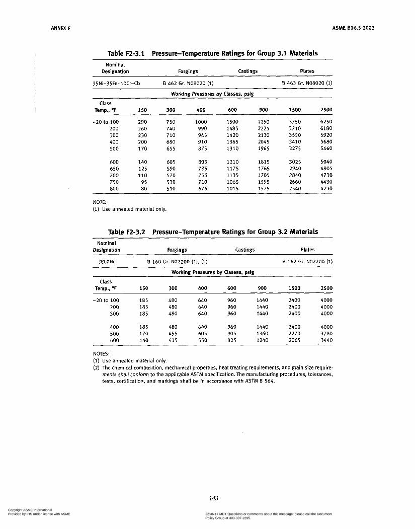
ANNEX F ASME 816.5-2003
Table F2-3.1 Pressure-Temperature Ratings for Group 3.1 Materials ~~~~~~ ~
Nominal Designation Forgings Castings Plates
35Ni-35Fe-1OCr-Cb B 462 Gr. NO8020 (1) B 463 Gr. NO8020 (1)
Working Pressures by Classes, psig
Temp., OF 150 300 400 600 900 1500 2500
-20 to 100 290 750 1000 1500 2250 3750 6250
300 230 710 945 1420 2130 3550 5920
500 170 655 875 1310 1965 3275 5460
Class
200 260 740 990 1485 2225 3710 6180
400 200 680 910 1365 2045 3410 5680
600 140 605 ao5 1210 ia15 3025 5040 650 1 2 5 590 785 1175 1765 2940 4905 700 110 5 70 755 1135 1705 2840 4730 750 95 530 710 1065 1595 2660 4430 ao0 ao 510 675 1015 1525 2540 4230
NOTE: ( i ) Use annealed material only.
Table F2-3.2 Pressure-Temperature Ratings for Group 3.2 Materials ~~ ~
Nominal Designation Forgings Castings Plates
99.ONi B 160 Gr. NO2200 (11, (2) B 162 Gr. NO2200 (i)
Working Pressures bv Classes. min Class
Temp., O F 150 300 400 600 900 1500 2500
-20 to 100 185 480 640 960 1440 2400 4000 200 185 480 640 960 1440 2400 4000 300 i a 5 480 640 960 1440 2400 4000
400 ia5 480 640 960 1440 2400 4000 500 170 455 605 90 5 1360 2270 3780 600 140 41 5 5 50 825 1240 2065 3440
NOTES: (1) Use annealed material only. (2) The chemical composition, mechanical properties, heat treating requirements, and grain size require-
ments shall conform to the applicable ASTM specification. The manufacturing procedures, tolerances, tests, certification, and markings shall be in accordance with ASTM B 564.
143
Copyright ASME International Provided by IHS under license with ASME
Document provided by IHS Licensee=Qatar Petroleum/5943408001, 09/19/200422:36:17 MDT Questions or comments about this message: please call the DocumentPolicy Group at 303-397-2295.
--```,,`,``,,,,`,,``````,,``,`-`-`,,`,,`,`,,`---

ASME 816.5-2003 ANNEX F
Table F2-3.3 Pressure-Temperature Ratings for Group 3.3 Materiais Nominal Designation Forgings Castings Plates
~
99.ONi-LOW C 6160 Gr. NO2201 (l), (2) ~ ~~~
B 162 Gr. NO2201 (1)
Working Pressures by Classes, psig
Temp., OF 150 300 400 600 900 1500 2500
-20 to 100 90 240 320 480 720 1200 2000 200 90 230 305 460 690 1150 1920
Class
300 a5 225 300 450 675 1130 iaao 400 a5 225 300 450 675 1130 iaao 500 a 5 225 300 450 675 1130 iaao
600 a5 225 300 450 675 1130 iaao 650 a 5 225 300 44 5 670 1115 1a60 700 a5 225 300 445 670 1115 1a60 750 a5 220 295 440 660 1105 1a40 800 ao 215 290 430 650 ioao iaoo
a50 65 210 280 420 635 1055 1760 900 50 205 275 415 620 1030 1720 950 35 195 260 395 5 90 985 1640 1000 20 190 255 380 570 950 i 580 1050 . . . ao 110 165 245 410 685
1100 . . . 70 90 135 205 345 570 1150 . . . 50 70 105 155 2 5 5 430 1200 . . . 40 55 ao 125 205 345
NOTES: (1) Use annealed material only. (2) The chemical composition, mechanical properties, heat treating requirements, and grain size require-
ments shall conform to the applicable ASTM specification. The manufacturing procedures, tolerances, tests, certification, and markings shall be in accordance with ASTM B 564.
144 Copyright ASME International Provided by IHS under license with ASME
Document provided by IHS Licensee=Qatar Petroleum/5943408001, 09/19/200422:36:17 MDT Questions or comments about this message: please call the DocumentPolicy Group at 303-397-2295.
--```,,`,``,,,,`,,``````,,``,`-`-`,,`,,`,`,,`---
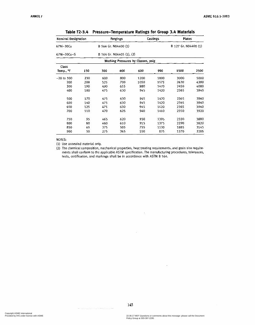
ANNEX F ASME B16.5-2003
Table F2-3.4 Pressure-Temperature Ratings for Group 3.4 Materials Nominal Designation Forgings Castings Plates
67Ni-30C~
67Ni-30Cu-S
B 564 Gr. NO4400 (1)
B 164 Gr. NO4405 ( l) , (2)
B 127 Gr. NO4400 (1)
Working Pressures by Classes, psig
Class Temp., O F 150 300 400 600 900 1500 2500
1800 1575 1470 1420
3000 2630 2450 2365
5000 4380 4080 3940
230 200 190 180
800 700 655 630
1200 1050
980 945
-20 to 100 200 300 400
600 5 2 5 490 475
500 600 650 700
170 140 125 110
475 475 475 470
630 630 630 625
945 945 945 940
1420 1420 1420 1410
2365 2365 2365 2350
3940 3940 3940 3920
750 800 850 900
95 80 65 50
465 460 375 275
620 610 505 365
930 91 5 755 550
1395 1375 1130
825
2330 2290 1885 1370
3880 3820 3145 2285
NOTES: (1) Use annealed material only. (2) The chemical composition, mechanical properties, heat treating requirements, and grain size require-
ments shall conform to the applicable ACTM specification. The manufacturing procedures, tolerances, tests, certification, and markings shall be in accordance with ASTM B 564.
145
Copyright ASME International Provided by IHS under license with ASME
Document provided by IHS Licensee=Qatar Petroleum/5943408001, 09/19/200422:36:17 MDT Questions or comments about this message: please call the DocumentPolicy Group at 303-397-2295.
--```,,`,``,,,,`,,``````,,``,`-`-`,,`,,`,`,,`---
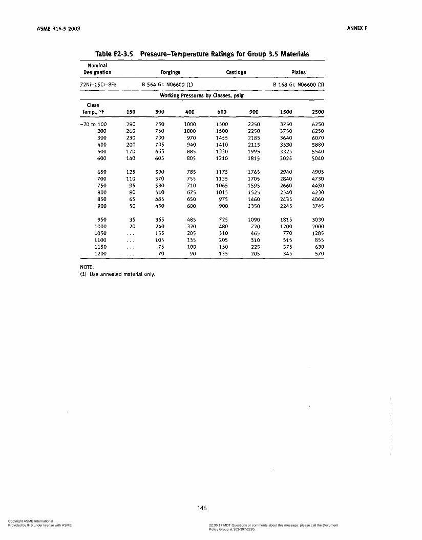
ASME 816.5-2003 ANNEX F
Table F2-3.5 Pressure-Temperature Ratings for Group 3.5 Materials
Nominal Designation Forgings Castings Plates
72Ni-15Cr-8Fe B 564 Gr. NO6600 (i) B 168 Gr. No6600 (1)
Working Pressures bv Classes, Dsin Class
Temp., O F 150 300 400 600 900 1500 2500
-20 to 100 200 300 400 500 600
290 260 230 200 170 140
750 750 730 705 665 605
1000 1 O00
970 940 a85 ao5
1500 1500 1455 1410 1330 1210
2250 2250
2115 1995
2185
ia15
3750 3750 3640 3530 3325 3025
6250 6250 6070
5540 5040
5880
650 700 750 800
900 a50
125 110
95
65 50
ao
590 570 530 510
450 485
785 755 710 675 650 600
1175 1135 1065 1015
975 900
1765 1705 1595 1525 1460 1350
2940
2660 2540 2435 2245
2840 4905 4730 4430 4230 4060 3745
950 1000 1050 1100 1150 1200
35 20
365 240 1 5 5 105
75 70
485 320 205 135 1 O0 90
725 480 310 205 150 135
1090 720 465 310 225 205
i a 1 5 1200 770 515 375 345
3030 2000
855 630 570
1285 ... . . . . . . ...
NOTE: (i) Use annealed material only.
146
Copyright ASME International Provided by IHS under license with ASME
Document provided by IHS Licensee=Qatar Petroleum/5943408001, 09/19/200422:36:17 MDT Questions or comments about this message: please call the DocumentPolicy Group at 303-397-2295.
--```,,`,``,,,,`,,``````,,``,`-`-`,,`,,`,`,,`---
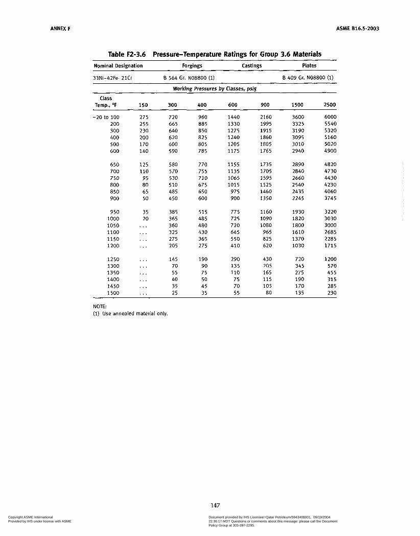
ANNEX F ASME B16.5-2003
Table F2-3.6 Pressure-Temperature Ratings for Group 3.6 Materials Nominal Designation Forgings Castings Plates
33Ni-42Fe-21Cr B 564 Gr. NO8800 (1) B 409 Gr. NO8800 (1)
Working Pressures by Classes, psig
Temp., O F 150 300 400 600 900 1500 2500
-20 to 100 275 720 960 1440 2160 3600 6000 200 255 665 885 1330 1995 3325 5540 300 230 640 850 1275 1915 3190 5320 400 200 620 82 5 1240 1860 3095 5160 500 170 600 805 1205 1805 3010 5020 600 140 590 785 1175 1765 2940 4900
Class
650 125 580 770 1 1 5 5 1735 2890 4820 700 110 570 755 1135 1705 2840 4730 750 95 530 710 1065 1595 2660 4430 800 80 510 675 1015 1525 2540 4230 850 65 485 650 975 1460 2435 4060 900 50 450 600 900 1350 2245 3745
950 35 385 515 775 1160 1930 3220 1000 20 365 485 725 1090 1820 3030 1050 . . . 360 480 720 1080 1800 3000 1100 . . . 325 430 645 965 1610 2685 1150 . . . 275 365 550 825 1370 2285 1200 ... 205 275 410 620 1030 1715
1250 . . . 145 190 290 430 720 1200 1300 . . . 70 90 135 205 345 570 1350 . . . 5 5 75 110 165 275 455 1400 ... 40 50 75 1 1 5 190 31 5 1450 . . . 35 45 70 105 170 285 1500 ... 25 35 55 80 135 230
NOTE: (I) Use annealed material only.
147
Copyright ASME International Provided by IHS under license with ASME
Document provided by IHS Licensee=Qatar Petroleum/5943408001, 09/19/200422:36:17 MDT Questions or comments about this message: please call the DocumentPolicy Group at 303-397-2295.
--```,,`,``,,,,`,,``````,,``,`-`-`,,`,,`,`,,`---
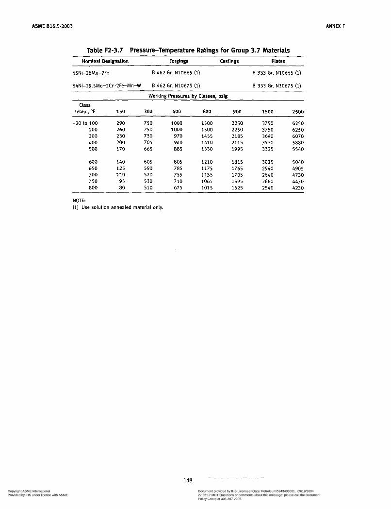
ASME 816.5-2003 ANNEX F
Table F2-3.7 Pressure-Temperature Ratings for Group 3.7 Materials Nominal Designation Forgings Castings Plates
65Ni-28Mo-2Fe
64Ni-29.5Mo-2Cr-2Fe-Mn-W
B 462 Gr. N10665 (i)
B 462 Gr. N10675 (i)
B 333 Gr. N10665 (1)
B 333 Gr. N10675 (i) ~ ~~
Working Pressures by Classes, psig
Class Temp., O F 1 5 0 300 400 600 900 1500 2500
-20 to 100 290 750 1000 1500 2250 3750 6250 200 260 750 1000 1500 2250 3750 6250 300 230 730 970 1455 2185 3640 6070 400 200 705 940 1410 2115 3530 5880 500 170 665 885 1330 1995 3325 5540
600 140 605 805 1210 1815 3025 5040 650 125 590 785 1175 1765 2940 4905 700 110 570 755 1135 1705 2840 4730 750 95 530 710 1065 1595 2660 4430 800 80 510 675 1015 1525 2540 4230
NOTE: (1) Use solution annealed material only.
148 Copyright ASME International Provided by IHS under license with ASME
Document provided by IHS Licensee=Qatar Petroleum/5943408001, 09/19/200422:36:17 MDT Questions or comments about this message: please call the DocumentPolicy Group at 303-397-2295.
--```,,`,``,,,,`,,``````,,``,`-`-`,,`,,`,`,,`---
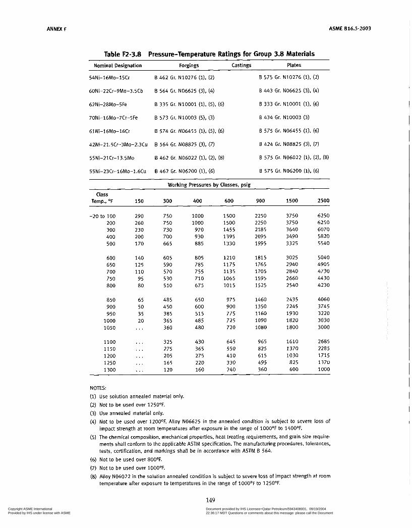
ANNEX F ASME B16.5-2003
Table F2-3.8 Pressure-Temperature Ratings for Group 3.8 Materials Nominal Designation Forgings Castings Plates
54Ni-16Mo-15Cr
60Ni-22Cr-9Mo-3.5Cb
62Ni-28Mo-5Fe
70Ni-16Mo-7Cr-5Fe
61 Ni-1 6Mo-16Cr
42Ni-21.5Cr-3Mo-2.3Cu
55Ni-21 Cr-13.5Mo
55Ni-23Cr-16Mo-1.6Cu
B 462 Gr. N10276 (i), (2)
B 564 Gr. NO6625 (3). (4)
B 335 Gr. N10001 (i). (5), (6)
B 573 Gr. N10003 (5). (3)
B 574 Gr. NO6455 (l), (5), (6)
B 564 Gr. NO8825 (3), (7)
B 462 Gr. NO6022 (l), (2), (8)
B 462 Gr. NO6200 (i), (6)
B 575 Gr. N10276 (l), (2)
B 443 Gr. NO6625 (3), (4)
B 333 Gr. N10001 (l), (6)
B 434 Gr. N10003 (3)
B 575 Gr. NO6455 (l), (6)
B 424 Gr. NO8825 (3). (7)
B 575 Gr. NO6022 (1). (2). (8)
B 575 Gr. NO6200 (l), (6) ~~~ ~
Working Pressures by Classes, psig
Temp., O F 150 300 400 600 900 1500 2500 Ciass
-20 to 100 200 300 400 500
600 650 700 750 800
850 900 950
1000 1050
1100 1150 1200 1250 1300
290 260 230 200 170
140 125 110
95 80
65 50 35 20 . . .
. . .
. . .
. . .
...
. . .
750 750 730 700 665
605 590 570 530 510
485 450 385 365 360
325 275 205 165 120
1000 1000
970 930 885
805 785 755 710 675
650 600 515 485 480
430 365 275 220 160
1500 1500 1455 1395 1330
1210 1175 1135 1065 1015
975 900 775 72 5 720
645 550 410 330 240
2250 2250 2185 2095 1995
1815 1765 1705 1595 1525
1460 1350 1160 1090 1080
965 825 61 5 495 360
3750 3750 3640 3490 3325
3025 2940 2840 2660 2540
2435 2245 1930 1820 1800
1610 1370 1030
825 600
6250 6250 6070 5820 5540
5040 4905 4730 4430 4230
4060 3745 3220 3030 3000
2685 2285 1715 1370 1000
NOTES: Use solution annealed material only. Not to be used over 1250'F. Use annealed material only. Not to be used over 120OoF. Alloy NO6625 in the annealed condition is subject to severe loss of impact strength at room temperatures after exposure in the range of 100O'F to 1400'F.
The chemical composition, mechanical properties, heat treating requirements, and grain size require- ments shall conform to the applicable ASTM specification. The manufacturing procedures, tolerances, tests, certification, and markings shall be in accordance with ASTM B 564.
Not to be used over 8OOOF. Not to be used over 100O'F.
Alloy NO6022 in the solution annealed condition is subject to severe loss of impact strength at room temperature after exposure to temperatures in the range of 100O'F to 1250'F.
149 Copyright ASME International Provided by IHS under license with ASME
Document provided by IHS Licensee=Qatar Petroleum/5943408001, 09/19/200422:36:17 MDT Questions or comments about this message: please call the DocumentPolicy Group at 303-397-2295.
--```,,`,``,,,,`,,``````,,``,`-`-`,,`,,`,`,,`---
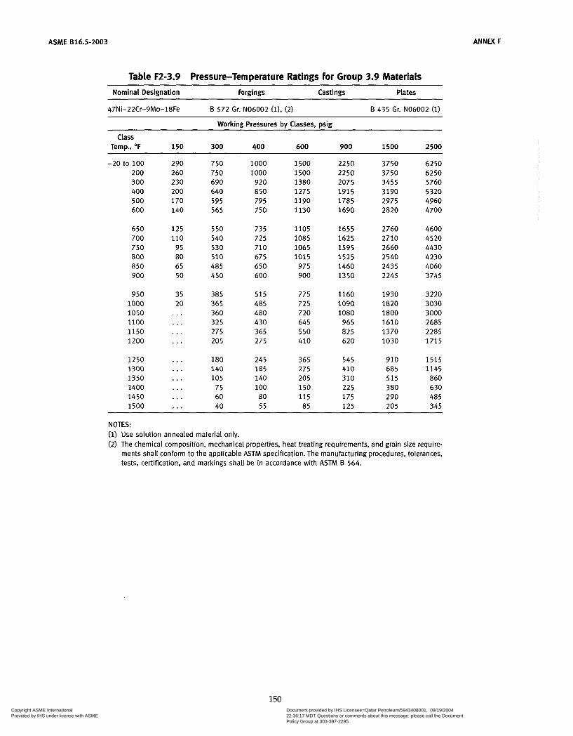
ASME 816.5-2003 ANNEX F
Table F2-3.9 Pressure-Temperature Ratings for Group 3.9 Materials ~~ ~~ ~
Nominal Designation Forgings Castings Plates
47Ni-22Cr-gMo-18Fe B 572 Gr. NO6002 (i). (2) B 435 Gr. NO6002 (1)
Working Pressures by Classes, psig
Temp., OF 150 300 400 600 900 1500 2500
-20 to 100 290 750 1 O00 1500 2 2 5 0 3750 6250 200 260 750 1000 1500 2250 3750 6250 300 230 690 920 1380 2075 3455 5760 400 200 640 850 1275 1915 3190 5320 500 170 595 79 5 1190 1785 2975 4960 600 140 565 750 1130 1690 2820 4700
Class
650 125 550 735 1105 1655 2760 4600 700 110 540 72 5 1085 1625 2710 4520 750 95 530 710 1065 1595 2660 4430 800 80 510 67 5 1015 1525 2540 4230 850 65 485 650 975 1460 2435 4060 900 50 450 600 900 1350 2245 3745
950 35 385 515 775 1160 1930 3220 1000 20 365 485 725 1090 1820 3030 1050 . . . 360 480 720 1080 1800 3000 1100 . . . 325 430 645 965 1610 2685 1150 . . . 275 365 550 825 1370 2285 1200 . . . 205 275 410 620 1030 1715
1250 ... 180 245 365 545 910 1515 1300 . . . 140 185 275 410 685 1145 1350 . . . 105 140 205 310 515 860 1400 . . . 75 1 O0 150 225 380 630 1450 . . . 60 80 115 175 290 485 1500 . . . 40 5 5 85 125 205 345
NOTES: (1) Use solution annealed material only. (2) The chemical composition, mechanical properties, heat treating requirements, and grain size require-
ments shall conform to the applicable ASTM specification. The manufacturing procedures, tolerances, tests, certification, and markings shall be in accordance with ASTM 6 564.
150 Copyright ASME International Provided by IHS under license with ASME
Document provided by IHS Licensee=Qatar Petroleum/5943408001, 09/19/200422:36:17 MDT Questions or comments about this message: please call the DocumentPolicy Group at 303-397-2295.
--```,,`,``,,,,`,,``````,,``,`-`-`,,`,,`,`,,`---
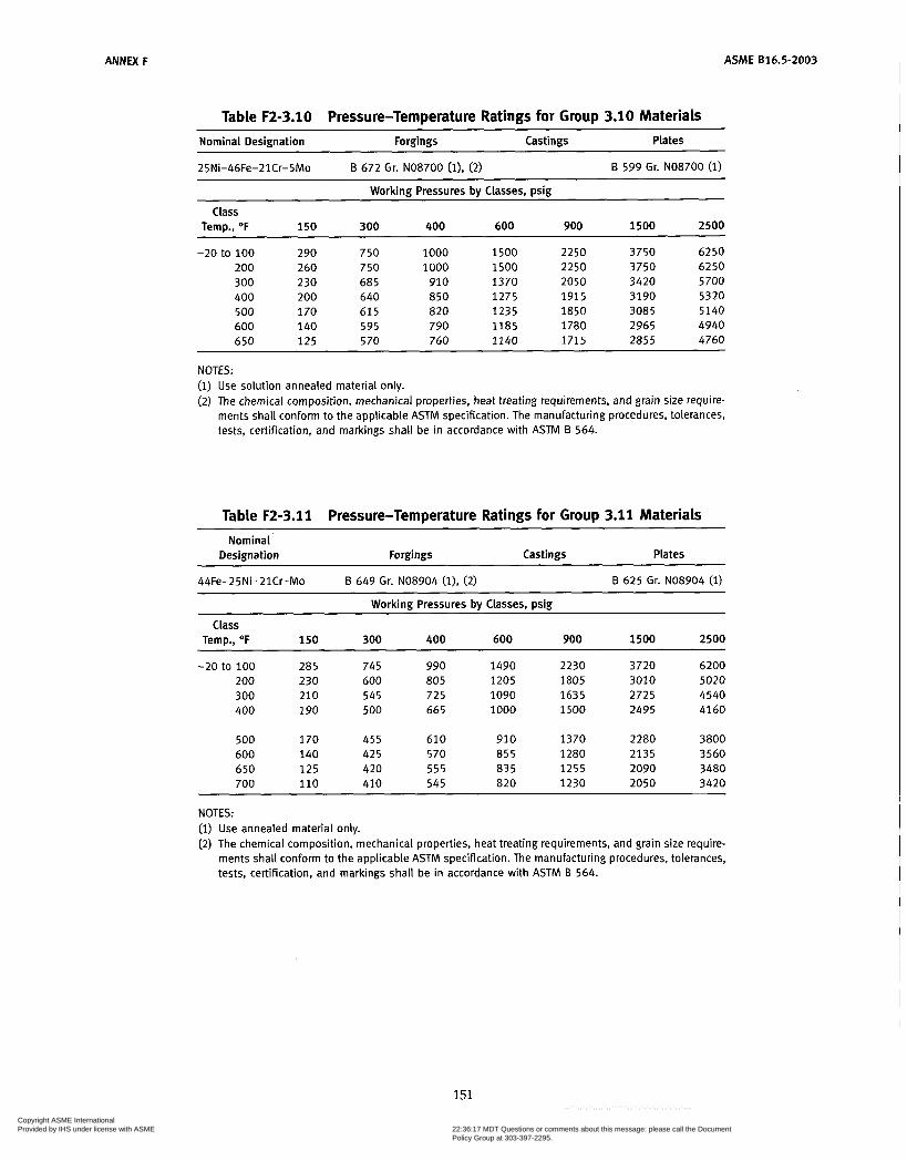
ANNEX F
Table F2-3.10 Pressure-Temperature Ratings for Group 3.10 Materials
ASME B16.5-2003
~~ ~
Nominal Designation Forgings Castings Plates
B 599 Gr. NO8700 (1) 25Ni-46Fe-21Cr-5Mo B 672 Gr. NO8700 (l), (2)
Working Pressures bv Classes, psig
Class Temp., O F 150 300 400 600 900 1500 2500
-20 to 100 290 750 1000 1500 2250 3750 6250 200 260 7 50 1000 1500 2250 3750 6250 300 230 685 910 1370 2050 3420 5 700 400 200 640 850 1275 1915 3190 5320 500 170 615 820 1235 1850 3085 5140 600 140 595 790 1185 1780 2965 4940 650 125 5 70 760 1140 1715 2855 4760
NOTES: (1) Use solution annealed material only. (2) The chemical composition, mechanical properties, heat treating requirements, and grain size require-
ments shall conform to the applicable ASTM specification. The manufacturing procedures, tolerances, tests, certification, and markings shall be in accordance with ASTM B 564.
Table F2-3.11 Pressure-Temperature Ratings for Group 3.11 Materials ~~~
Nominal Designation Forgings Castings Plates
~~
44Fe-25Ni-21Cr-Mo B 649 Gr. NO8904 (l), (2) B 625 Gr. NO8904 (1)
Working Pressures bv Classes, psig ~
Class Temp., O F 150 300 400 600 900 1500 2500
-20 to 100 200 300 400
500 600 650 700
285 230 210 190
170 140 125 110
745 600 545 500
455 425 420 410
990 805 725 665
610 570 555 545
1490 1205 1090 1000
910 855 835 820
2230 1805 1635 1500
1370 1280 1255 1230
3720 3010 2725 2495
2280 2135 2090 2050
6200 5020 4540 4160
3800 3560 3480 3420
NOTES: (1) Use annealed material only. (2) The chemical composition, mechanical properties, heat treating requirements, and grain size require-
ments shall conform to the applicable ASTM specification. The manufacturing procedures, tolerances, tests, certification, and markings shall be in accordance with ASTM B 564.
151
Copyright ASME International Provided by IHS under license with ASME
Document provided by IHS Licensee=Qatar Petroleum/5943408001, 09/19/200422:36:17 MDT Questions or comments about this message: please call the DocumentPolicy Group at 303-397-2295.
--```,,`,``,,,,`,,``````,,``,`-`-`,,`,,`,`,,`---
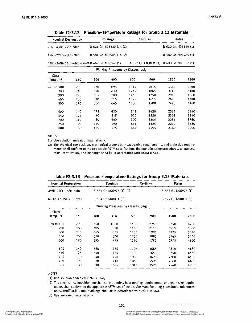
ASME 816.5-2003
Table F2-3.12 Pressure-Temperature Ratings for Group 3.12 Materials
ANNEX F
Nominal Designation Forgings Castings Plates
26Ni-43Fe-22Cr-5Mo B 621 Gr. NO8320 (i), (2) B 620 Gr. NO8320 (1)
47Ni-22Cr-20Fe-7Mo
46Fe-24Ni-21Cr-6Mo-Cu-N B 462 Gr. NO8367 (1)
B 581 Gr. NO6985 (1). (2) 6 582 Gr. NO6985 (1)
A 351 Gr. CN3MM (1) 6 688 Gr. NO8367 (1)
Working Pressures by Classes, psig
Temp., O F 150 300 400 600 900 1500 2500
-20 to 100 260 670 89 5 1345 201 5 3360 5600 200 240 620 830 1245 1865 3110 5180 300 225 585 780 1165 1750 2915 4860 400 200 540 715 1075 1615 2690 4480 500 170 500 665 1000 1500 2495 4160
Class
600 140 475 630 94 5 1420 2365 3940 650 125 460 61 5 920 1380 2305 3840 700 110 450 600 900 1355 2255 3760 750 95 440 590 885 1325 2210 3680 800 80 430 575 865 1295 2160 3600
NOTES: (1) Use solution annealed material only. (2) The chemical composition, mechanical properties, heat treating requirements, and grain size require-
ments shall conform to the applicable ASTM specification. The manufacturing procedures, tolerances, tests, certification, and markings shall be in accordance with ASTM 6 564.
Table F2-3.13 Pressure-Temperature Ratings for Group 3.13 Materials Nominal Designation Forgings Cast in gs Plates
49Ni-25Cr-18Fe-6Mo B 581 Gr. NO6975 (1). (2) B 582 Gr. NO6975 (1)
Ni-Fe-Cr-Mo-Cu-Low C B 564 Gr. NO8031 (3) B 625 Gr. NO8031 (3)
Workinn Pressures bv Classes, risin Class
Temp., O F 150 300 400 600 900 1500 2500
-20 to 100 290 750 1000 1500 2250 3750 6250 200 260 705 940 1405 2110 3515 5860 300 230 665 885 1330 1995 3325 5540 400 200 630 840 1260 1885 3145 5240 500 170 595 795 1190 1785 2975 4960
600 140 560 750 1125 1685 2810 4680 650 125 550 735 1100 1650 2750 4580 700 110 540 720 1080 1620 2700 4500 750 95 530 710 1065 1595 2660 4430 800 80 510 675 1015 1525 2540 4230
NOTES: (1) Use solution annealed material only. (2) The chemical composition, mechanical properties, heat treating requirements, and grain size require-
ments shall conform to the applicable ASTM specification. The manufacturing procedures, tolerances, tests, certification, and markings shall be in accordance with ASTM 6 564.
(3) Use annealed material only.
152 Copyright ASME International Provided by IHS under license with ASME
Document provided by IHS Licensee=Qatar Petroleum/5943408001, 09/19/200422:36:17 MDT Questions or comments about this message: please call the DocumentPolicy Group at 303-397-2295.
--```,,`,``,,,,`,,``````,,``,`-`-`,,`,,`,`,,`---

ANNEX F ASME B16.5-2003
Table F2-3.14 Pressure-Temperature Ratings for Group 3.14 Materials Nominal Designation Forgings Castings Plates
47Ni-22Cr-19Fe-6Mo B 581 Gr. NO6007 (l), (2) B 582 Gr. NO6007 (1)
40Ni-29Cr-15Fe-5Mo B 462 Gr. NO6030 (l), (3) B 582 Gr. NO6030 (i), (3)
Working Pressures bv Classes, wig
Class Temp., O F 150 300 400 600 900 1500 2500
-20 to 100 200 300 400
500 600 650 700
750 800 850 900
950 1000
275 250 230 200
170 140 125 110
95 80 65 50
35 20
720 650 600 565
540 520 510 505
500 500 485 450
385 365
960 865 800 750
715 690 680 675
670 665 650 600
5 1 5 485
1440 1295 1200 1130
1075 1035 1020 1015
1005 1 O00
975 900
775 725
2160 1945 1800 1690
1615 1 5 5 5 1535 1520
1505 1500 1460 1350
1160 1090
3600 3240 3000 2820
2690 2590 2555 2530
2510 2495 2435 2245
1930 1820
6000 5400 5000 4700
4480 4320 4260 4220
4180 4160 4060 3745
3220 3030
NOTES: (1) Use solution annealed material only. (2) The chemical composition, mechanical properties, heat treating requirements, and grain size require-
ments shall conform to the applicable ASTM specification. The manufacturing procedures, tolerances, tests, certification, and markings shall be in accordance with ASTM B 564.
(3) Not to be used over 80OOF.
153 Copyright ASME International Provided by IHS under license with ASME
Document provided by IHS Licensee=Qatar Petroleum/5943408001, 09/19/200422:36:17 MDT Questions or comments about this message: please call the DocumentPolicy Group at 303-397-2295.
--```,,`,``,,,,`,,``````,,``,`-`-`,,`,,`,`,,`---

ASME 816.5-2003 ANNEX F
Table F2-3.15 Pressure-Temperature Ratings for Group 3.1 5 Materiais
Nominal Designation Forgings Castings Plates
33Ni-42Fe-21Cr B 564 Gr. NO8810 (1) 6 409 Gr. NO8810 (1)
Working Pressures by Classes, psig
Temp., O F 150 300 400 600 900 1500 2500 Class
-20 to 100 200 300 400 500 600
230 210 200 190 170 140
600 550 520 490 465 440
800 735 695 655 620 585
1200 1105 1040
980 925 880
1800 1655 1560 1470 1390 1320
3000 2760 2605 2450 2 3 1 5 2195
5000 4600 4340 4080 3860 3660
650 700 750 800 850 900
125 110
95 80 65 50
430 420 410 400 395 385
575 555 545 535 525 515
860 835 820 800 785 775
1290 1255 1230 1200 1180 1160
2150 2090 2050 2005 1970 1930
3580 3480 3420 3340 3280 3220
950 1000 1050 1100 1150 1200
35 20
380 365 3 50 325 275 205
505 485 465 430 365 275
760 725 700 64 5 550 410
1140 1090 1050
965 825 620
1895 1820 1750 1610 1370 1030
3160 3030 2915 2685 2285 1715
. . .
. . .
. . .
1250 1300 1350 1400 1450 1500
180 140 105
75 60 40
245 185 140 1 O0
80 5 5
365 275 205 150 115 85
545 410 310 225 175 125
910 685 5 1 5 380 290 20 5
1515 1145 860 630 485 345
. . .
. . .
...
. . .
. . . I . .
NOTE: (i) Use solution annealed material only.
154 Copyright ASME International Provided by IHS under license with ASME
Document provided by IHS Licensee=Qatar Petroleum/5943408001, 09/19/200422:36:17 MDT Questions or comments about this message: please call the DocumentPolicy Group at 303-397-2295.
--```,,`,``,,,,`,,``````,,``,`-`-`,,`,,`,`,,`---
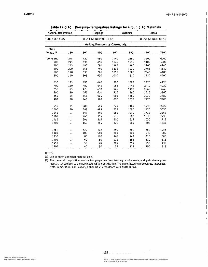
ANNEX F
Table F2-3.16 Pressure-Temperature Ratings for Group 3.16 Materials Nominal Designation Forgings Castings Plates
35Ni-19Cr-11@i B 511 Gr. NO8330 (1). (2) B 536 Gr. NO8330 (1)
ASME 616.5-2003
Working Pressures by Classes, psig
Temp., OF 150 300 400 600 900 1500 2500
-20 to 100 275 720 960 1440 2160 3600 6000 200 245 635 850 1270 1910 3180 5300 300 225 595 790 1185 1780 2965 4940 400 200 5 5 5 740 1115 1670 2785 4640 500 170 530 705 1055 1585 2640 4400 600 140 505 670 1010 1510 2520 4200
Class
650 1 2 5 495 660 990 1485 2470 4120 700 110 480 645 965 1445 2410 4020 750 95 475 630 94 5 1420 2365 3940 800 80 465 620 925 1390 2315 3860 850 65 455 60 5 905 1360 2270 3780 900 50 445 590 890 1330 2220 3700
950 35 385 5 1 5 775 1160 1930 3220 1000 20 365 485 725 1090 1820 3030 1050 ... 345 455 685 1030 1715 2855 1100 ... 265 355 535 800 1335 2230 1150 ... 205 275 410 61 5 1030 1715 1200 ... 160 215 320 485 805 1345
1250 ... 130 175 260 390 650 1085 1300 ... 105 140 215 320 530 885 1350 ... 80 110 165 245 410 685 1400 ... 60 .80 1 2 5 185 310 515 1450 ... 50 70 105 155 255 430 1500 ... 40 50 75 115 190 315
NOTES: (1) Use solution annealed material only. (2 ) The chemical composition, mechanical properties, heat treating requirements, and grain size require-
ments shall conform to the applicable ASTM specification. The manufacturing procedures, tolerances, tests, certification, and markings shall be in accordance with ASTM B 564.
155 Copyright ASME International Provided by IHS under license with ASME
Document provided by IHS Licensee=Qatar Petroleum/5943408001, 09/19/200422:36:17 MDT Questions or comments about this message: please call the DocumentPolicy Group at 303-397-2295.
--```,,`,``,,,,`,,``````,,``,`-`-`,,`,,`,`,,`---

ASME 616.5-2003 ANNEX F
Table F2-3.17 Pressure-Temperature Ratings for Group 3.17 Materials Nominal Designation Forgings castings Plates
A 351 Gr. CN7M (1)
Working Pressures bv Classes, D S k
Class Temp.. O F 150 300 400 600 900 1500 2500
-20 to 100 230 600 800 1200 1800 3000 5000 200 200 520 690 1035 1555 2590 4320 300 180 465 620 930 1395 2330 3880 400 160 420 565 845 1265 2110 3520 500 150 390 520 780 1165 1945 3240 600 140 3 60 480 720 1080 1800 3000
NOTE: (1) Use solution annealed material only.
Table F3 Permissible Imperfections in Flange Facing Finish for Raised Face and large Male and
Female Flanges Maximum Radial Maximum Depth and
Projection of Radiai Projection of Imperfections Which Imperfections Which Are No Deeper Than Are Deeper Than the
the Bottom of the Bottom of the N PS Serrations, in. Serrations, in.
'h 3A 1
1 1 'h
2 2% 3 l h 3
4
5 6 8 10 12
14 16 18 20 24
0.12 0.12 0.12 0.12 0.1 2
0.1 2 0.12 0.18 0.25 0.25
0.25 0.25 0.31 0.31 0.31
0.31 0.38 0.50 0.50 0.50
0.06 0.06 0.06 0.06 0.06
0.06 0.06 0.06 0.12 0.12
0.12 0.12 0.18 0.18 0.18
0.18 0.18 0.25 0.25 0.25
156 Copyright ASME International Provided by IHS under license with ASME
Document provided by IHS Licensee=Qatar Petroleum/5943408001, 09/19/200422:36:17 MDT Questions or comments about this message: please call the DocumentPolicy Group at 303-397-2295.
--```,,`,``,,,,`,,``````,,``,`-`-`,,`,,`,`,,`---

. . . . . . . . . . . . . . . . . . . . . . . . . . . . . . . . . . . . . . . . . . . . . . . . . . . . . . . . . . . .
. . . . . . . . . . . . . . . . . . . .
. . . . . . . . . . . . . . . . . . . . . . . . . . . . . . . . . . : : : I
. . . . . . . . . . . . . . . . . . . . . . . . . . . . . . : : : : : I
157
Copyright ASME International Provided by IHS under license with ASME
Document provided by IHS Licensee=Qatar Petroleum/5943408001, 09/19/200422:36:17 MDT Questions or comments about this message: please call the DocumentPolicy Group at 303-397-2295.
--```,,`,``,,,,`,,``````,,``,`-`-`,,`,,`,`,,`---

ASME 816.5-2003 ANNEX F
23 deg
Table F5 Dimensions of Ring Joint Facings (Ali Pressure Rating Classes)
1 2 3 4 5 6 7 8 9 10 11 12
Nominal Pipe Size Groove Dimensions
Class Class Pitch Depth, Radius at Class Class 400 Class 900 Class Class Groove Diameter, E Width, Bottom, 150 300 [Note (2)] 600 [Note (3)] 1500 2500 Number P [Note (l)] i R
. . . lh . . . R11 . . . 12
13 . . . 14 ... 1 5
% 16 . . . 17 1 18
. . . 19
. . . 20
1% 21 ... 22 1% 23 . . . 24 . . . 25
2 26
1.344 1.562 1.688 1.750 1.875
2.000 2.250 2.375 2.562 2.688
2.844 3.250 3.250 3.750 4.000
4.000 4.250 4.375 4.500 4.625
4.875 5.000 5.188 5.188 5.375
5.875 5.875 6.188 6.375 6.750
7.125 7.500 7.625 7.625 8.312
8.312 9.000 9.750 10.625 10.625
0.219 0.281 0.03 0.250 0.344 0.03 0.250 0.344 0.03 0.250 0.344 0.03 0.250 0.344 0.03
0.250 0.344 0.03 0.250 0.344 0.03 0.250 0.344 0.03 0.250 0.344 0.03 0.250 0.344 0.03
0.312 0.469 0.03 0.250 0.344 0.03 0.312 0.469 0.03 0.312 0.469 0.03 0.250 0.344 0.03
0.312 0.469 0.03 0.312 0.469 0.03 0.375 0.531 0.06 0.250 0.344 0.03 0.312 0.469 0.03
0.312 0.469 0.03 0.375 0.531 0.06 0.250 0.344 0.03 0.312 0.469 0.03 0.312 0.469 0.03
0.250 0.344 0.03 0.312 0.469 0.03 0.438 0.656 0.06 0.312 0.469 0.03 0.250 0.344 0.03
0.312 0.469 0.03 0.500 0.781 0.06 0.250 0.344 0.03 0.312 0.469 0.03 0.312 0.469 0.03
0.375 0.531 0.06 0.500 0.781 0.06 0.250 0.344 0.03 0.312 0.469 0.03 0.438 0.656 0.06
lh
3A ...
... . . .
. . . 3A
... . . . 1 ...
... 1
% ...
. . .
... . . . ...
1 ... 1 lA
1 . . . 1 IA
. . .
. . . . . . ... 1 lL4 ...
1 IA . . . ... 1
...
. . . ... ...
... 1 lh 1 lh ... 1 lh
... . . . 2 . . .
... 2
... . . . 2% . . . . . . 2% ... ... . . . ... 3 ...
. . . (4)
... 3 (4)
3% . . . ... 3 lh
. . . . . .
2 . . .
. . .
. . . ... . . .
. . . 2
2% ... ...
. . . ...
. . . 2% . . . 27
. . . ... 2% 28
... . . . . . . 29
. . . ... . . . 30
3 . . . ... 31 ... . . . 3 32 . . . ... ... 33 ... . . . . . . 34 . . . 3 . . . 35
. . . . . . . . . 36 4 . . . . . . 37 ... . . . 4 38 . . . 4 . . . 39 ... . . . . . . 40
5 . . . . . . 41 . . . . . . 5 42 . . . . . . . . . 43 . . . 5 . . . 44 6 . . . . . . 45
. . . 6 . . . 46
... ,.. 6 47
. . . . . . . . . 48 8 ... . . . 49 . . . 8 . . . 50
... . . . ...
. . . (4)
3 (4)
3lh
...
. . . ... . . .
... . . . 4 ... ... 4
. . . 4
. . . 4 . . . . . .
... . . . . . .
. . . ... 5 ...
. . . 5
... . . . 6 . . . ... . . . . . . 6
...
5 5 . . . . . . . . . 6
... 6
. . . . . . ... ...
. . . ... . . . 8 . . .
... 8
. . . . . . 8 ...
8 . . .
158
Copyright ASME International Provided by IHS under license with ASME
Document provided by IHS Licensee=Qatar Petroleum/5943408001, 09/19/200422:36:17 MDT Questions or comments about this message: please call the DocumentPolicy Group at 303-397-2295.
--```,,`,``,,,,`,,``````,,``,`-`-`,,`,,`,`,,`---
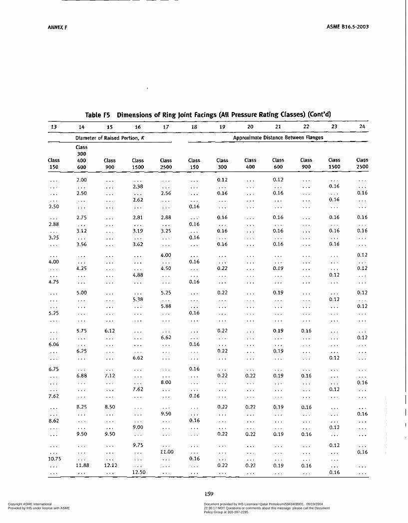
ANNEX F ASME 816.5-2003
Table F5 Dimensions of Ring Joint Facings (All Pressure Rating Classes) (Cont’d)
13 14 15 16 17 18 19 20 21 22 23 24
Diameter of Raised Portion, K
Class 300
Approximate Distance Between Flanges
Class 400 Class Class Class Class Class Class Class Class Class Class 150 600 900 1500 2500 150 300 400 600 900 1500 2500
. . .
. . .
. . .
. . . 2.50
... 2.88 ...
3.25 ... ...
4.00 . . . ...
4.75
...
...
... 5.25 ... ... ... 6.06 ... ...
6.75 ... . . . ...
7.62
. . .
. . . 8.62 ... ... ... . . .
10.75 . . . ...
2.00
2.50 ...
...
. . . 2.75
3.12
3.56
. . .
...
. . .
. . . 4.25 ... . . . 5.00 ... . . . ... . . . 5.75 . . . . . . 6.25 . . . . . . 6.88 . . . . . . . . . 8.25 . . . . . . . . . 9.50
. . .
. . .
... 11.88 ...
. . .
...
. . .
...
. . .
...
. . .
...
. . .
...
...
. . .
...
...
...
. . .
...
. . .
...
. . . 6.12 ... ... ... ... ... 7.12 ... ... ... 8.50 . . . ... . . .
9.50
...
. . .
... 12.12 ...
. . . 2.38 . . .
2.62 . . .
2.81 ...
3.19
3.62 . . .
...
. . .
... 4.88 ... . . .
5.38 . . . . . . . . . . . . . . . . . . . . .
6.62
. . .
. . .
. . . 7.62 . . . . . . . . . . . .
9.00 . . .
9.75 . . . . . . ...
12.50
. . .
. . . 2.56 . . . . . . 2.88 ...
3.25 . . . . . .
4.00
4.50 . . .
. . .
. . . 5.25 . . . 5.88 . . . . . . ...
6.62 . . . . . . ... ... . . .
8.00 . . . ... ...
9.50 ... . . . ... ... 11.00 ... . . . ...
. . .
...
. . .
... 0.16
. . . 0.16
0.16 . . .
...
... 0.16 ... . . .
0.16
. . .
. . .
. . . 0.16 . . . . . . . . . 0.16 . . . . . .
0.16 . . . . . . . . .
0.16
. . .
. . . 0.16 . . . . . . . . . . . .
0.16 . . . . . .
0.12
0.16 ...
...
. . . 0.16
0.16
0.16
...
...
. . .
. . . 0.22 . . . ...
0.22 . . . ... . . . ...
0.22 . . . ...
0.22 ... . . .
0.22 ... . . . . . .
0.22 . . . . . . . . .
0.22
. . .
. . .
. . . 0.22 ...
. . .
. . .
. . .
. . .
. . .
. . .
..,
. . .
. . .
. . .
. . .
. . .
. . .
. . .
. . .
. . .
. . .
. . .
. . .
. . .
. . .
. . .
. . .
. . .
. . .
. . . 0.22 . . . . . . . . .
0.22 . . . . . . . . .
0.22
. . .
. . .
. . . 0.22 ...
0.12
0.16 . . .
. . .
... 0.16
0.16
0.16
...
. . .
. . .
... 0.19 ... . . .
0.19 ... . . . ... . . .
0.19 ... . . . 0.19 . . . . . .
0.19 . . . ... . . .
0.19 ... . . . ...
0.19
...
...
. . . 0.19 . . .
...
. . .
...
. . .
. . .
. . .
...
. . .
...
. . .
. . .
...
. . .
...
. . .
. . .
...
. . .
...
. . . 0.16 ... . . . ... . . . ...
0.16 . . . ... . . . 0.16 ... . . . ...
0.16
. . .
...
. . . 0.16 . . .
. . . 0.16
0.16 ...
... 0.16
0.16
0.16
...
...
. . .
. . .
. . . 0.12 . . . . . .
0.12 . . . . . . . . . . . . ... . . . . . .
0.12
. . .
...
. . . 0.12 . . . . . . ... . . .
0.12 ...
0.12 ... ... . . .
0.16
. . .
. . . 0.16 . . . . . .
0.16
0.16 . . .
. . .
. . . 0.1 2
0.12 . . .
. . .
. . . 0.12
0.12 . . .
. . .
. . .
. . . 0.12 . . . . * . . . . . . . . . .
0.16 . . . . . . . . .
0.16 . . . ... . . . . . .
0.16
. . .
. . .
159 Copyright ASME International Provided by IHS under license with ASME
Document provided by IHS Licensee=Qatar Petroleum/5943408001, 09/19/200422:36:17 MDT Questions or comments about this message: please call the DocumentPolicy Group at 303-397-2295.
--```,,`,``,,,,`,,``````,,``,`-`-`,,`,,`,`,,`---

ANNEX F ASME 816.5-2003
Table F5 Dimensions of Ring Joint Facings (All Pressure Rating Classes) (Cont’d)
1 2 3 4 5 6 7 8 9 10 11 12
Nominal Pipe Size Groove Dimensions
Class Class Pitch Depth, Radius at Class Class 400 Class 900 Class Class Groove Diameter E Width Bottom 150 300 [Note (2)] 600 [Note (3)] 1500 2500 Number P [Note (l)] F R
. . . 10 . . . . . . . . . 12 . . . . . . 14 . . . . . . . . . . . . 16 . . . . . . . . . 18 . . . ... . . . 20 . . . . . . . . . 24 . . . . . . . . .
. . .
. . . 10 . . . . . . . . . 12 . . . . . . . . . 14 . . . . . . . . . 16
. . .
. . .
. . . 18 . . . ... . . . 20 . . . . . . . . . 24 . . . . . .
. . .
... 10 ... . . . . . . 12 . . . . . . . . . 14 . . . . . . . . . 16
. . .
...
... 18 . . . .., . . . 20 . . . . . . . . . 24 . . . ...
...
... 10 . . . ... . . . 12 . . . ... . . . 14 . . . . . . . . . 16
. . .
. . .
. . . 18 . . . ... . . . 20 . . . . . . ... 24 . . . . . .
. . .
... 10 ... . . . . . . 12 . . . . . . . . . ... 14 ... . . . ... 16 . . . . . . ... 18
...
. . .
. . . 20 . . . ... . . . 24 . . .
...
...
... 10 ... . . . ... 12 ... . . . . . . . . . 14 . . . ... . . . 16 . . . ... . . . 18 ... . . . ... 20
...
. . .
... 24
8 5 1 ... 52 . . . 53 ... 54 10 55
. .. 56
. . . 57
... 58
. . . 59 12 . 60
... 61
. . . 62
. . . 63
. . . 64
. . . 65
. . . 66
... 67
. . . 68
... 69
. . . 70
. . . 71
. . . 72
... 73
. . . 74
... 75
... 76
. . . 77
. . . 78
... 79
11.000 12.000 12.750 12.750 13.500
15.000 15.000 15.000 15.625 16.000
16.500 16.500 16.500 17.875 18.500
18.500 18.500 20.375 21.000 21.000
21.000 22.000 23.000 23.000 23.000
26.500 27.250 27.250 27.250
0.562 0.250 0.312 0.438 0.688
0.250 0.312 0.562 0.250 0.688
0.312 0.438 0.625 0.250 0.312
0.438 0.688 0.250 0.312 0.500
0.688 0.250 0.375 0.500 0.688
0.250 0.438 0.625 0.812
0.906 0.344 0.469 0.656 1.188
0.344 0.469 0.906 0.344 1.312
0.469 0.656 1.062 0.344 0.469
0.656 1.188 0.344 0.469 0.781
1.188 0.344 0.531 0.781 1.312
0.344 0.656 1.062 1.438
0.06 0.03 0.03 0.06 0.09
0.03 0.03 0.06 0.03 0.09
0.03 0.06 0.09 0.03 0.03
0.06 0.09 0.03 0.03 0.06
0.09 0.03 0.06 0.06 0.09
0.03 0.06 0.09 0.09
160
Copyright ASME International Provided by IHS under license with ASME
Document provided by IHS Licensee=Qatar Petroleum/5943408001, 09/19/200422:36:17 MDT Questions or comments about this message: please call the DocumentPolicy Group at 303-397-2295.
--```,,`,``,,,,`,,``````,,``,`-`-`,,`,,`,`,,`---

ASME 816.5-2003 ANNEX F
Table F5 Dimensions of Ring Joint Facings (All Pressure Rating Classes) (Cont'd) 13 14 15 16 17 18 19 20 21 22 23 24
Diameter of Raised Portion, K
Class 300
Approximate Distance Between Flanges
Class 400 Class Class Class Class Class Class Class Class Class Class 150 600 900 1500 2500 150 300 400 600 900 1500 2500
. . . 13.00 . . . ... . . .
16.00 ... . . .
16.75 . . . . . . ... . . .
19.00 . . . . . . ...
21.50 ... . . . . . .
23.50 . . . ... . . .
28.00 ... . . . ...
...
. . . 14.00 . . . ... ...
16.25 ... . . . ...
18.00 . . . ... . . .
20.00
... ,,. ...
22.62 . . . ... . . .
25.00 ... . . . . . .
29.50 . . . ...
,.. . . .
14.25 ... ... ...
16.50 ... . . . . . . ...
18.38 ... ... . . .
20.62 ... . . . ...
23.38
. . .
...
. . . 25.50 . . . . . . ...
30.38 . . .
...
. . .
. . . 14.62 . . . . . . . . .
17.25 . . . . . . . . . . . .
19.25 . . . . . . . . .
21.50 . . . . . . . . .
24.12 ... ... . . .
26.50
...
. . .
. . . 31.25
13.38 ... ... . . .
16.75
...
...
. . .
... 19.50
. . .
...
. . .
... 1 . .
. . .
...
. . .
...
...
...
...
...
. . .
...
...
. . .
...
. . .
... 0.16 . . . ... I . .
0.16 ... ... 0.12 ... ... . . . ...
0.12 ... ... ...
0.12 ... . . . . . .
0.12 . . . ... . . .
0.12 . . . ... . . .
...
. . . 0.22 ... ... ...
0.22 . . . . . . ...
0.22 . . . ... ...
0.22
. . .
. . *
. . . 0.22 . . . . . . . . .
0.22 . . . ... ...
0.25 . . . ...
...
. . . 0.22 ... . . . . . .
0.22 . . . . . . ...
0.22 . . . . . . . . .
0.22
. . .
...
. . . 0.22 . . . ... . . .
0.22 . . . . . . . . .
0.25 . . . . . .
,.. . . .
0.19 ... ... ...
0.19 ... ... . . . 0.19 ... . . . ...
0.19
. . .
...
... 0.19 ... ... . . .
0.19 ... . . . . . .
0.22 . . . ...
,,. ...
0.16 ... ... ...
0.16 ... . . . ... ...
0.16 . . . ... . . .
0.16 ... ... ...
0.19
...
. . .
... 0.19 . . . ... ...
0.22 ...
...
...
... 0.16 ... ... . . .
0.19 ... ... ... ...
0.22 ... . . . . . .
0.31 ... . . . ...
0.31 ... . . . ...
0.38
. . .
. . .
... 0.44
0.19 ... . . . . . .
0.25
. . .
. . .
. . .
. . . 0.31
...
...
. . .
. . .
. . .
. . .
. . .
. . .
. . .
. . .
. . .
. . .
. . .
. . .
. . .
. . .
. . .
. . .
. . .
GENERAL NOTES: (a) Dimensions are in inches. (b) For facing requirements for flanges and flanged fittings, see para. 6.4.1 and Fig. F7. (c) For facing requirements for lapped joints, see para. 64.3 and Fig. F7. (d) See para 4.2.7 for marking requirements. NOTES: (I) Height of raised portion is equal to the depth of groove dimension E, but is not subjected to the tolerances for E. For-
(2) Use Class 600 in sizes NPS 'h to NPS 3'h for Class 400. (3) Use Class 1500 in sizes NPS % to NPS 2% for Class 900. (4) For ring joints with lapped flanges in Classes 300 and 600. ring and groove number R30 are used instead of R31. TOLERANCES: E (depth) +0.016, -0.0 F (width) *0.008 P (pitch diameter) 10.005 R (radius at bottom)
mer full-face contour may be used.
R 5 0.06 +0.03, -0.0 R > 0.06 * 0.03
23 deg (angle) i 'h deg
161 Copyright ASME International Provided by IHS under license with ASME
Document provided by IHS Licensee=Qatar Petroleum/5943408001, 09/19/200422:36:17 MDT Questions or comments about this message: please call the DocumentPolicy Group at 303-397-2295.
--```,,`,``,,,,`,,``````,,``,`-`-`,,`,,`,`,,`---
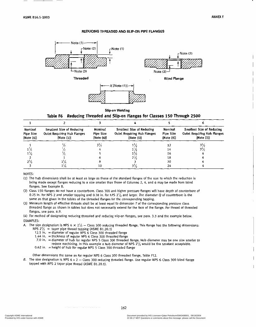
ASME 616.5-2003 ANNEX F
REDUCING THREADED AND SLIP-ON PIPE FLANGES
- Note (1)- I J. $Note (2) I
- t
LNote (3)
Threaded
Note (3)-1
Blind Flange
Slip-on Welding
Table F6 Reducing Threaded and Slip-on Flanges for Classes 150 Through 2500 1 2 3 4 5 6
Nominal Smallest Size of Reducing Nominal Smallest Size of Reducing Nominal Smallest Size of Reducing Pipe Size Oulet Requiring Hub Flanges Pipe Size Oulet Requiring Hub Flanges Pipe Size Oulet Requiring Hub Flanges [Note (411 [Note (111 [Note (411 [Note (111 [Note (411 [Note (111
1 1 'A 1 lh
2% 2
3
3 lh 4 5 6 8 10
1 lh 12 1 lh 14 1 'h 16 2% 18
3 20 3 lA 24
3 l h 3 lh 4 4 4 4
NOTES: The hub dimensions shall be at least as large as those of the standard flanges of the size to which the reduction is being made except flanges reducing to a size smaller than those of Columns 2, 4, and 6 may be made from blind flanges. See Example B. Class 150 flanges do not have a counterbore. Class 300 and higher pressure flanges will have depth of counterbore of 0.25 in. for NPS 2 and smaller tapping and 0.38 in. for NPS 2% and larger. The diameter Q of counterbore is the same as that given in the tables of the threaded flanges for the corresponding tapping. Minimum length of effective threads shall be at least equal to dimension Tof the corresponding pressure class threaded flange as shown in tables but does not necessarily extend for the face of the flange. For thread of threaded flanges, see para. 6.9. For method of designating reducing threaded and reducing slip-on flanges, see para. 3.3 and the example below.
EXAMPLES: A. The size designation is NPS 6 x 2% - Class 300 reducing threaded flange. This flange has the following dimensions:
NPS 2% = taper pipe thread tapping (ASME 81.20.1) 12.5 in. = diameter of regular NPS 6 Class 300 threaded flange 1.44 in. =thickness of regular NPS 6 Class 300 threaded flange
7.0 in. = diameter of hub for regular NPS 5 Class 300 threaded flange. Hub diameter may be one size smaller to
0.62 in. = height of hub for regular NPS 5 Class 300 threaded flange reduce machining. In this example a hub diameter of NPS 2% would be the smallest acceptable.
Other dimensions the same as for regular NPS 6 Class 300 threaded flange, Table F12. B. The size designation is NPS 6 x 2 - Class 300 reducing threaded flange. Use regular NPS 6 Class 300 blind Flange
tapped with NPS 2 taper pipe thread (ASME 81.20.1).
162
Copyright ASME International Provided by IHS under license with ASME
Document provided by IHS Licensee=Qatar Petroleum/5943408001, 09/19/200422:36:17 MDT Questions or comments about this message: please call the DocumentPolicy Group at 303-397-2295.
--```,,`,``,,,,`,,``````,,``,`-`-`,,`,,`,`,,`---
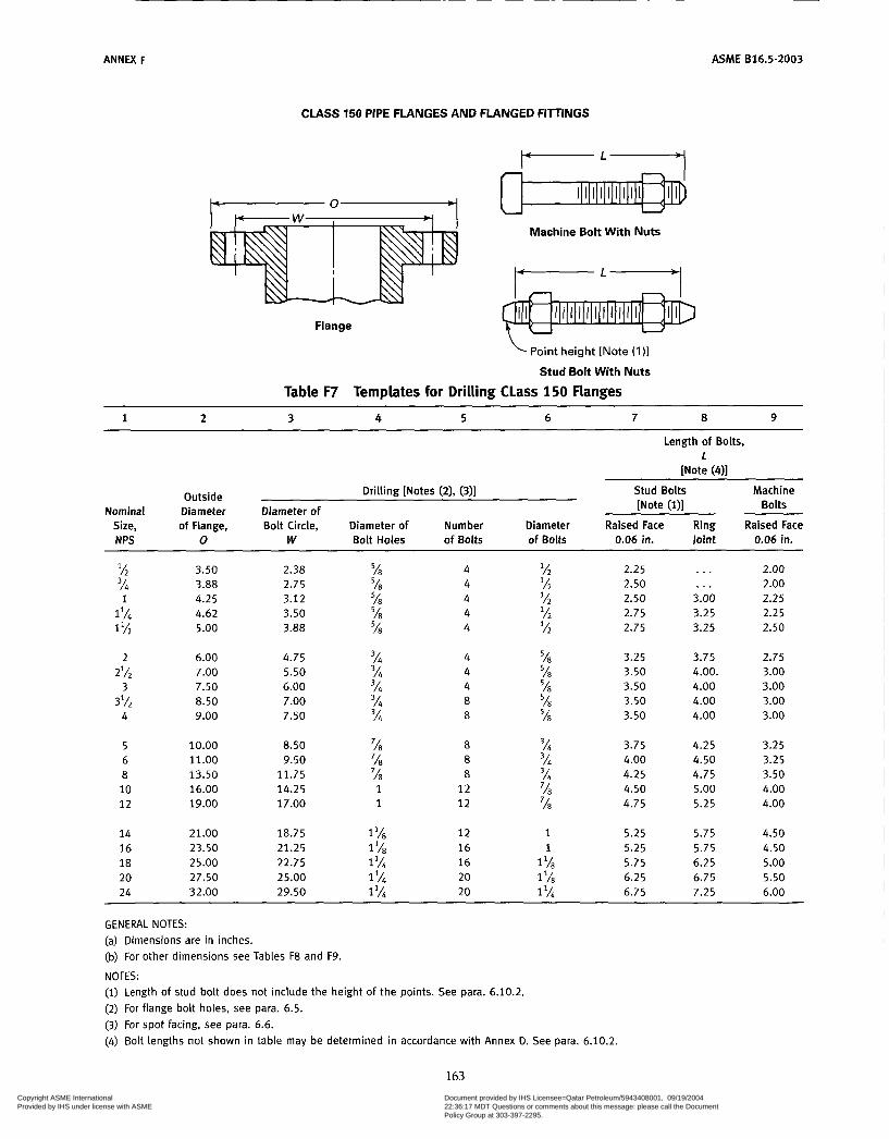
ANNEX F ASME 816.5-2003
CLASS 150 PIPE FLANGES AND FLANGED FIlTINGS
YL-I
Machine Bol t With Nuts
Flange
Point height [Note (111
Stud Bolt Wi th Nuts
Table F7 Templates for Drilling CLass 150 Flanges
Length of Bolts, 1
[Note (41 Drilling [Notes (2), (311 Stud Bolts Machine Outside
[Note (111 Bolts Nominal Diameter Diameter of Size, of Flange, Bolt Circle, Diameter of Number Diameter Raised Face Ring Raised Face N PS O W Bolt Holes of Bolts of Bolts Joint 0.06 in. 0.06 in.
lh 3h
1 %
2%
3Ih
1 1
2
3
4
5 6 8 10 12
14 16 18 20 24
3.50 3.88 4.25 4.62 5.00
6.00 7.00 7.50 8.50 9.00
10.00 11 .o0 i3.50 16.00 19.00
21.00 23.50 25.00 27.50 32.00
2.38 2.75 3.12 3.50 3.88
4.75 5.50 6.00 7.00 7.50
8.50 9.50 11.75 14.25 17.00
18.75 21.25 22.75 25.00 29.50
4 4 4 4 4
4 4 4 8
3h 8
% 'A7 % 'A7 %
%4
3/i 3h 3/i
% 8 % 8 '18 8 1 12 1 12
1 I18 12
1 '14 20
1 '18 16 1% 16
1 20
2.25 2.50 2.50
lh 2.75 'h 2.75
% 3.25 '18 3.50 % 3.50 'h 3.50 'A7 3.50
3h 3.75 3h 4.00 3h 4.25 'A7 4.50 '18 4.75
1 5.25 1 5.25
1 '18 6.25 1 6.75
I1/É 5.75
. . .
. , . 3.00 3.25 3.25
3.75 4.00. 4.00 4.00 4.00
4.25 4.50 4.75 5.00 5.25
5.75 5.75 6.25 6.75 7.25
2.00 2.00 2.25 2.25 2.50
2.75 3.00 3.00 3.00 3.00
3.25 3.25 3.50 4.00 4.00
4.50 4.50 5.00 5.50 6.00
GENERAL NOTES: (a) Dimensions are in inches. (b) For other dimensions see Tables F8 and F9.
NOTES: (I) Length of stud bolt does not include the height of the points. See para. 6.10.2. (2) For flange bolt holes, see para. 6.5. (3) For spot facing, see para. 6.6. (4) Bolt lengths not shown in table may be determined in accordance with Annex D. See para. 6.10.2.
163 Copyright ASME International Provided by IHS under license with ASME
Document provided by IHS Licensee=Qatar Petroleum/5943408001, 09/19/200422:36:17 MDT Questions or comments about this message: please call the DocumentPolicy Group at 303-397-2295.
--```,,`,``,,,,`,,``````,,``,`-`-`,,`,,`,`,,`---
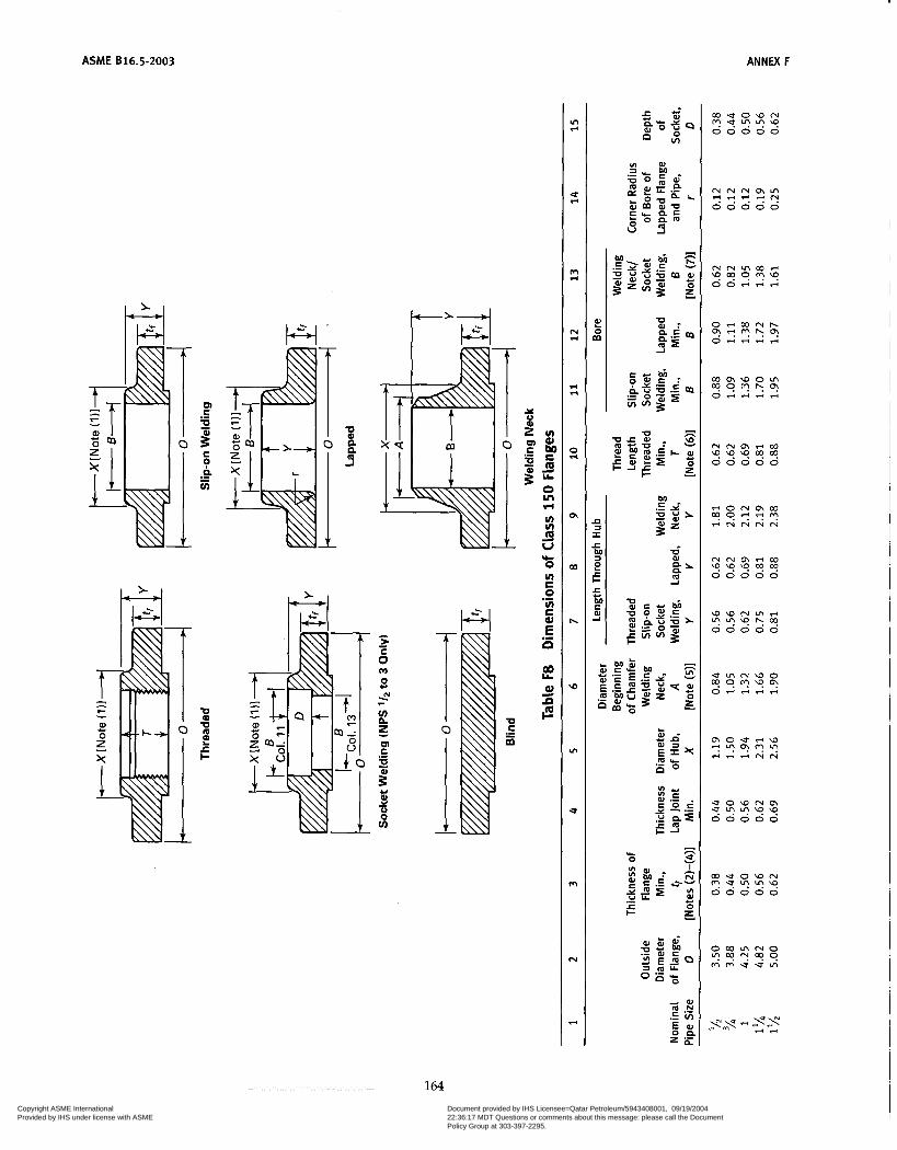
~
ASME 616.5-2003
u) u) m U
O u) E O u) E aJ
d
\L-
.- E n .- 00 LL
0)
ñ F
in d
U d
m d
N FI
FI r(
z
o,
W
h
\o
in
U
m
N
..I
- h L
O 2
164 Copyright ASME International Provided by IHS under license with ASME
Document provided by IHS Licensee=Qatar Petroleum/5943408001, 09/19/200422:36:17 MDT Questions or comments about this message: please call the DocumentPolicy Group at 303-397-2295.
--```,,`,``,,,,`,,``````,,``,`-`-`,,`,,`,`,,`---

ANNEX F ASME 616.5-2003
m m - 0 0 0 . . u ? \ % : : . . . . . . . . . . . . . . . . . . . .
u 0 0 0 0 0 0 0 0 0 ? " v \ " v !
0 0 0 0 0
0 0 0 0 0 " L ? " " "
- c) P E 8 # - VI
E m
O in r(
VI ' V I m U
O VI E O VI E
G
d
%
.-
.- E P
al = F
ñ U Yi O
N S M S U N M
165 Copyright ASME International Provided by IHS under license with ASME
Document provided by IHS Licensee=Qatar Petroleum/5943408001, 09/19/200422:36:17 MDT Questions or comments about this message: please call the DocumentPolicy Group at 303-397-2295.
--```,,`,``,,,,`,,``````,,``,`-`-`,,`,,`,`,,`---
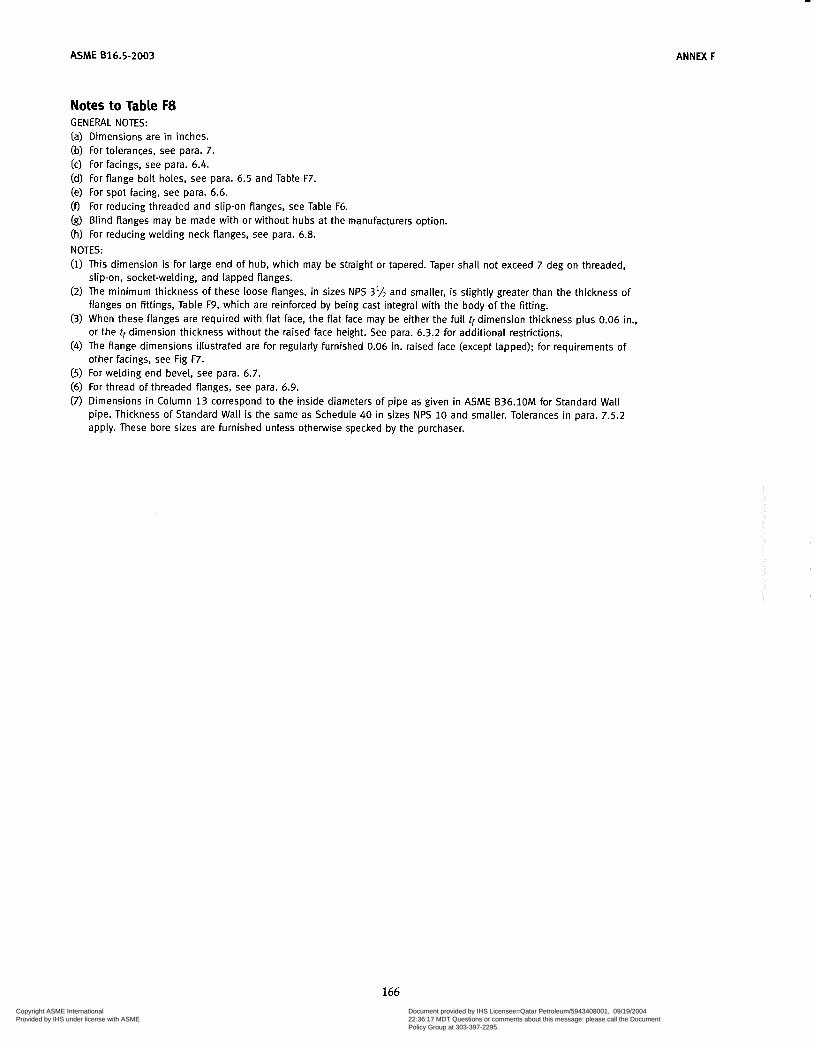
ASME 816.5-2003
Notes to Table F8 GENERAL NOTES:
ANNEX F
(a) Dimensions are in inches. (b) For tolerances, see para. 7. (c) For Facings, see para. 6.4. (d) For flange bolt holes, see para. 6.5 and Table F7. (e) For spot facing, see para. 6.6. (9 For reducing threaded and slip-on flanges, see Table F6. (g) Blind flanges may be made with or without hubs at the manufacturers option. (h) For reducing welding neck flanges, see para. 6.8. NOTES: (1) This dimension is for large end of hub, which may be straight or tapered. Taper shall not exceed 7 deg on threaded,
(2) The minimum thickness of these loose flanges, in sizes NPS 3% and smaller, is slightly greater than the thickness of
(3) When these flanges are required with flat face, the flat face may be either the full tf dimension thickness plus 0.06 in.,
(4) The flange dimensions illustrated are for regularly furnished 0.06 in. raised face (except lapped); for requirements of
(5) For welding end bevel, see para. 6.7. (6) For thread of threaded flanges, see para. 6.9. (7) Dimensions in Column 13 correspond to the inside diameters of pipe as given in ASME B36.10M for Standard Wall
slip-on, socket-welding, and lapped flanges.
flanges on fittings, Table F9, which are reinforced by being cast integral with the body of the fitting.
or the tf dimension thickness without the raised face height. See para. 6.3.2 for additional restrictions.
other facings, see Fig F7.
pipe. Thickness of Standard Wall is the same as Schedule 40 in sizes NPS 10 and smaller. Tolerances in para. 7.5.2 apply. These bore sizes are furnished unless otherwise specked by the purchaser.
166 Copyright ASME International Provided by IHS under license with ASME
Document provided by IHS Licensee=Qatar Petroleum/5943408001, 09/19/200422:36:17 MDT Questions or comments about this message: please call the DocumentPolicy Group at 303-397-2295.
--```,,`,``,,,,`,,``````,,``,`-`-`,,`,,`,`,,`---
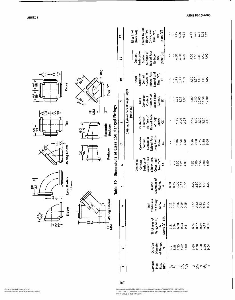
ANNEX F
v) v)
L o
0 al U
ASME 816.5-2003
m m o 0 0 0 0 0 : : ? . o v\?^494 . . 4 4 N N N M M M
. . m o m 0 0 0 0 0
.+NN N M ~ M ~ : : b o ? " 9 9 " 9
i N 'G û, 0, i.( i.( c-4 u-? "-3
I.... > o 0 0 0 ."" 0 0 0 0 0
riucoe a ~ m m m ???.u! 3 0 0 0 0 ?'9'9hQ? 0 0 0 0 0
167
Copyright ASME International Provided by IHS under license with ASME
Document provided by IHS Licensee=Qatar Petroleum/5943408001, 09/19/200422:36:17 MDT Questions or comments about this message: please call the DocumentPolicy Group at 303-397-2295.
--```,,`,``,,,,`,,``````,,``,`-`-`,,`,,`,`,,`---

~~
ASME 816.5-2003
n
c O
P
u Y
.- E t: L'
d I/ U
168
Copyright ASME International Provided by IHS under license with ASME
Document provided by IHS Licensee=Qatar Petroleum/5943408001, 09/19/200422:36:17 MDT Questions or comments about this message: please call the DocumentPolicy Group at 303-397-2295.
--```,,`,``,,,,`,,``````,,``,`-`-`,,`,,`,`,,`---

ASME 816.5-2003
v) 0 O c - c - O m
I m c m
3 O E
. . . . . . . . .
. . . . . . . . . . . . . . .
- h O %-I
u- O Y I - !$iL& . . . . . . . . . . . . . . . U m g I - z I
CI .-
O c
O O W W N ??.?.?u? 0 0 0 0 0
169 Copyright ASME International Provided by IHS under license with ASME
Document provided by IHS Licensee=Qatar Petroleum/5943408001, 09/19/200422:36:17 MDT Questions or comments about this message: please call the DocumentPolicy Group at 303-397-2295.
--```,,`,``,,,,`,,``````,,``,`-`-`,,`,,`,`,,`---
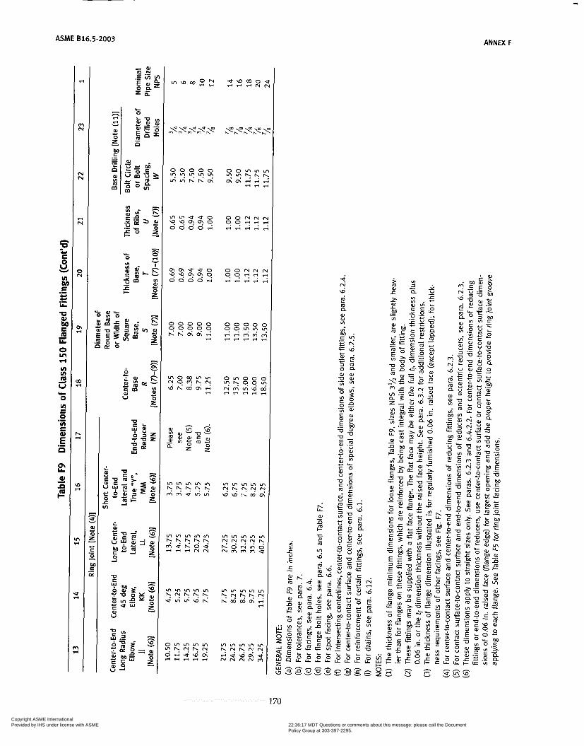
ASME 816.5-2003 ANNU F
r; LL
aJ L1 - P
i m a 0) a, VI
1 70
Copyright ASME International Provided by IHS under license with ASME
Document provided by IHS Licensee=Qatar Petroleum/5943408001, 09/19/200422:36:17 MDT Questions or comments about this message: please call the DocumentPolicy Group at 303-397-2295.
--```,,`,``,,,,`,,``````,,``,`-`-`,,`,,`,`,,`---
ANNEX F ASME 616.5-2003
Notes to Table F9 (Cont’d) (7) (8)
The base dimensions apply to all straight and reducing sizes. For reducing fittings, the size, and center-to-face dimension of base are determined by the size of the largest opening of fittings. In the case of reducing base elbows, orders shall specify whether the base shall be opposite the larger or smaller opening.
(9) Bases shall be plain faced, unless otherwise specified, and the center-to-base dimension R shall be the finished dimension.
(10) Bases may be cast integral or attached as weldments at the option of the manufacturer. (11) The bases of these fittings are intended for support in compression and are not to be used for anchors or supports in
tension or shear.
171
Copyright ASME International Provided by IHS under license with ASME
Document provided by IHS Licensee=Qatar Petroleum/5943408001, 09/19/200422:36:17 MDT Questions or comments about this message: please call the DocumentPolicy Group at 303-397-2295.
--```,,`,``,,,,`,,``````,,``,`-`-`,,`,,`,`,,`---
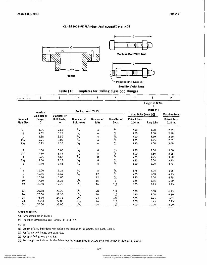
ASME B16.5-2003 ANNEX F
CLASS 300 PIPE FLANGES, AND FLANGED FITTINGS
FLY
Flange
Machine Bolt W i t h Nut
Point height [Note (111
Stud Bo l t With Nuts
Table F10 Templates for Drilling Class 300 Flanges
- 1 2 3 4 . 5 . 6 7 8 9
Outside Diameter of
Nominal Flange, Pipe Size O
l/2 3.75 3h 4.62 1 4.88
1% 5.25 1 l/í 6.12
Length of Bolts, 1
[Note (411 Drilling [Note (2). (3)] Diameter of Stud Bolts [Note (l)] Machine Bolts
Bolt Circle, Diameter of Number of Diameter of Raised Face Raised Face W Bolt Holes Bolts Bolts 0.06 in. Ring Joint 0.06 in.
2.62 5h 4 'A 2.50 3.00 2.25 3.25 3h 4 58 3.00 3.50 2.50 3.50 3h 4 58 3.00 3.50 2.50 3.88 3h 4 58 3.25 3.75 2.75 4.50 'h 4 3h 3.50 4.00 3.00
2 6.50 5.00 3h 8 =/á 3.50 4.00 3.00 2% 7.50 5.88 % 8 3h 4.00 4.50 3.25
3 8.25 6.62 'h 8 3h 4.25 4.75 3.50 3 l h 9.00 7.25 '18 8 3h 4.25 5.00 3.75
4 10.00 7.88 7 0 8 % 4.50 5.00 3.75
5 11.00 9.25 % 8 3/4 4.75 5.25 4.25 6 12.50 10.62 % 12 % 4.75 5.50 4.25
10 17.50 15.25 1 'h 16 1 6.25 6.75 5.50 8 15.00 13.00 1 12 '/s 5.50 6.00 4.75
12 20.50 17.75 1 '/4 16 llh 6.75 7.25 5.75
14 23.00 20.25 1 % 20 1 '/s 7.00 7.50 6.25 16 25.50 22.50 1 20 15% 7.50 8.00 6.50 18 28.00 24.75 1 24 1 'h 7.75 8.25 6.75 20 30.50 27.00 1 24 1% 8.00 8.75 7.25 24 36.00 32.00 1 5~ 24 1 'h 9.00 10.00 8.00
GENERAL NOTES: (a) Dimensions are in inches. (b) For other dimensions see, Tables F 1 1 and F12.
NOTES: (1) Length of stud bolt does not include the height of the points. See para. 6.10.2.
(2) For flange bolt holes, see para. 6.5. (3) For spot facing, see para. 6.6. (4) Bolt lengths not shown in the Table may be determined in accordance with Annex D. See para. 6.10.2.
172
Copyright ASME International Provided by IHS under license with ASME
Document provided by IHS Licensee=Qatar Petroleum/5943408001, 09/19/200422:36:17 MDT Questions or comments about this message: please call the DocumentPolicy Group at 303-397-2295.
--```,,`,``,,,,`,,``````,,``,`-`-`,,`,,`,`,,`---
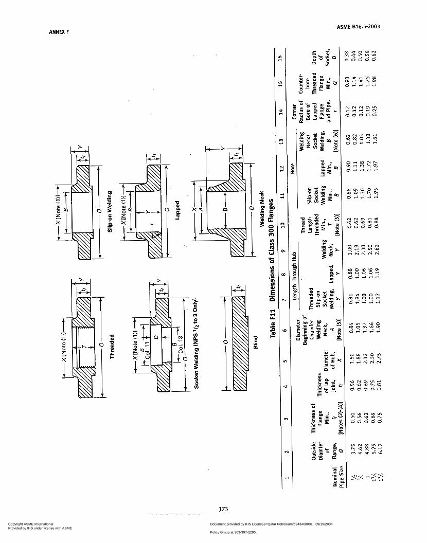
ANNEX F ASME 816.5-2003
u) u)
U IC o u1 c C
C
s
.- U
E E r r Y Q r - $
173
Copyright ASME International Provided by IHS under license with ASME
Document provided by IHS Licensee=Qatar Petroleum/5943408001, 09/19/200422:36:17 MDT Questions or comments about this message: please call the DocumentPolicy Group at 303-397-2295.
--```,,`,``,,,,`,,``````,,``,`-`-`,,`,,`,`,,`---

ASME 816.5-2003 ANNEX F
+ r i m m u ' u o o o o o 0 0 0 0 ???l. S ? " " . 5"" " " 0 0 0 0 0 0 0 0 0 0 O 0 0 O 0
i o u i o o 0 0 0 0 0 O 0 0 O 0
~ h M c n O r i N r n h 0 ' " N O 9 O?9"? 9 9 9 " 9
ri - - r i 3 N R % % m m
o + U
w - n i-
0) c m U vi
U ? c c .- \o
E O a O v)
.- +-a
L t
E
S U
S c
c
rm
1 74
Copyright ASME International Provided by IHS under license with ASME
Document provided by IHS Licensee=Qatar Petroleum/5943408001, 09/19/200422:36:17 MDT Questions or comments about this message: please call the DocumentPolicy Group at 303-397-2295.
--```,,`,``,,,,`,,``````,,``,`-`-`,,`,,`,`,,`---

ANNEX F ASME B16.5-2003
Notes to Table F11 NOTES: (1) This dimension is for large end of hub, which may be straight or tapered. Taper shall not exceed 7 deg on threaded,
slip-on, socket-welding, and lapped flanges. This dimension is defined as the diameter at the intersection between the hub taper and the back face of the flange.
(2) These flanges may be supplied with a flat face. The flat face may be either the full tf dimension thickness plus 0.06 in. or the tr dimension thickness without the raised face height. See para. 6.3.2 for additional restrictions.
(3) The flange dimensions illustrated are for regularly furnished 0.06 in raised face (except lapped); for requirements of other facings, see Fig. F-7.
(4) For welding end bevel, see para. 6.7. (5) For thread of threaded flanges, see para. 6.9. (6) Dimensions in Column 13 correspond to the inside diameters of pipe as give in ASME B36.10M for Standard Wall pipe.
Standard Wall dimensions are the same as Schedule 40 in sizes NPS 10 and smaller. Tolerances in para. 7.5.2 apply. These bore sizes are furnished unless otherwise specified by the purchaser.
175
Copyright ASME International Provided by IHS under license with ASME
Document provided by IHS Licensee=Qatar Petroleum/5943408001, 09/19/200422:36:17 MDT Questions or comments about this message: please call the DocumentPolicy Group at 303-397-2295.
--```,,`,``,,,,`,,``````,,``,`-`-`,,`,,`,`,,`---

ASME B16.5-2003 ANNEX F
I I I I I I I
o) U
d
u) a
œ
O A
29
B U
L Q u a
œ T
1 76
Copyright ASME International Provided by IHS under license with ASME
Document provided by IHS Licensee=Qatar Petroleum/5943408001, 09/19/200422:36:17 MDT Questions or comments about this message: please call the DocumentPolicy Group at 303-397-2295.
--```,,`,``,,,,`,,``````,,``,`-`-`,,`,,`,`,,`---
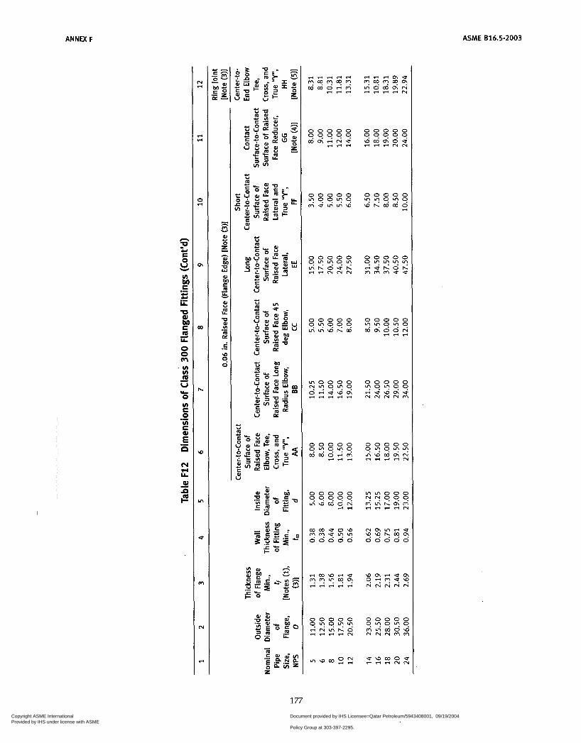
ANNEX F
n
E O
P
s m U
.- c U U
LL
U W
m Y,
O O rn v) v) m U
O uI E O v) E
.-
-
d
b h
.-
.- E o w
hl FI Y,
W
m c m ?;
ASME 816.5-2003
* *
O *
E m
Y I
0 0 0 0 0
e u h o h 0.""" rnrnrnue
0 0 0 0 0
m c h 0 0 N ."0"0
* e r r
0 0 0 0 0
e e w c h u "9.00 N W N N ~
177
Copyright ASME International Provided by IHS under license with ASME
Document provided by IHS Licensee=Qatar Petroleum/5943408001, 09/19/200422:36:17 MDT Questions or comments about this message: please call the DocumentPolicy Group at 303-397-2295.
--```,,`,``,,,,`,,``````,,``,`-`-`,,`,,`,`,,`---

ASME 816.5-2003 ANNEX F
v) al O r -
o UI m m
a 8 f2
. . . r n r n N N 0 0 0 0 0 0 . . . . ? Y ? . ' " " 9 9 ' " . . . r n r n a w w h h O O N
. . . O r n r n N O r n o o o o
u u r n r n w w h m O N : : : " h N ' 9 9 h ' " 9 ' " 9
+ +
. . . . . . . . . . . . . . . . . . . . . . . . . . . . . . . . . . . . . . .
178
Copyright ASME International Provided by IHS under license with ASME
Document provided by IHS Licensee=Qatar Petroleum/5943408001, 09/19/200422:36:17 MDT Questions or comments about this message: please call the DocumentPolicy Group at 303-397-2295.
--```,,`,``,,,,`,,``````,,``,`-`-`,,`,,`,`,,`---

ANNEX F ASME 816.5-2003
ri
U P r Y 8 E
4
VI
.- z .- Y U w
m Y O O m VI VI m U
O VI S O VI C
d
d
(c
.-
.- E P
$I
z iI0
LL al
e
m N
N N
e N
O N
m e
5
h *
W e
VI e
s
m e
3 - 5
5 E
E r
al O CI
CI
O
bl: -
e w m o u 4 + + "
. . . . . . . . . . . . . . .
-o al -c VI
c i= al
.-
5 n al
- - m z VI
CY c O in c al
U
al VI
.-
E .-
2 7
u 5
4 2 c
al
-o c m U-
!E U al
9. u)
al VI
3 r, VI VI al
K
-o
-
u E
179 Copyright ASME International Provided by IHS under license with ASME
Document provided by IHS Licensee=Qatar Petroleum/5943408001, 09/19/200422:36:17 MDT Questions or comments about this message: please call the DocumentPolicy Group at 303-397-2295.
--```,,`,``,,,,`,,``````,,``,`-`-`,,`,,`,`,,`---
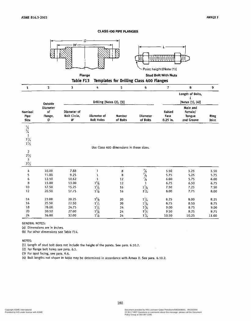
ASME 816.5-2003 ANNEX F
CLASS 400 PIPE FLANGES
Point height [Note (111
Flange Stud Bolt Wi th Nuts
Table F13 Templates for Drilling Class 400 Flanges
1 2 3 4 5 6 7 a 9
Length of Bolts, 1
Outside Drilling [Notes (2), (3)] [Notes (i), (41 Diameter Male and
Nominal of Diameter of Raised Female/ Pipe Flange, Bolt Circle, Diameter of Number Diameter Face Tongue Ring Size O W Bolt Holes of Bolts of Bolts 0.25 in. and Groove Joint
1% 1
1% Use Class 600 dimensions in these sizes.
L
2%
3% 3
4 10.00 7.88 1 8 58 5.50 5.25 5.50
6 12.50 10.62 1 12 'A 6.00 5.75 6.00 8 15.00 13.00 1% 12 1 6.75 6.50 6.75 10 17.50 15.25 1 Y4 16 1 'A3 7.50 7.25 7.50 12 20.50 17.75 1 16 1 IA 8.00 7.75 8.00
14 23.00 20.25 1 ' ~ 3 20 1 8.25 8.00 8.25 16 25.50 22.50 1% 20 1318 8.75 8.50 8.75
5 11.00 9.25 1 8 'A 5.75 5.25 5.75
18 28.00 24.75 1 % 24 1 5/, 9.00 8.75 9.00 20 30.50 27.00 1% 24 1 'A 9.50 9.25 9.75 24 36.00 32.00 1% 24 1% 10.50 10.25 11.00
GENERAL NOTES: (a) Dimensions are in inches. (b) For other dimensions see Table F14.
NOTES: (1) Length of stud bolt does not include the height of the points. See para. 6.10.2. (2) For flange bolt holes see para. 6.5. (3) For spot facing, see para. 6.6. (4) Bolt lengths not shown in table may be determined in accordance with Annex D. See para. 6.10.2.
180
Copyright ASME International Provided by IHS under license with ASME
Document provided by IHS Licensee=Qatar Petroleum/5943408001, 09/19/200422:36:17 MDT Questions or comments about this message: please call the DocumentPolicy Group at 303-397-2295.
--```,,`,``,,,,`,,``````,,``,`-`-`,,`,,`,`,,`---
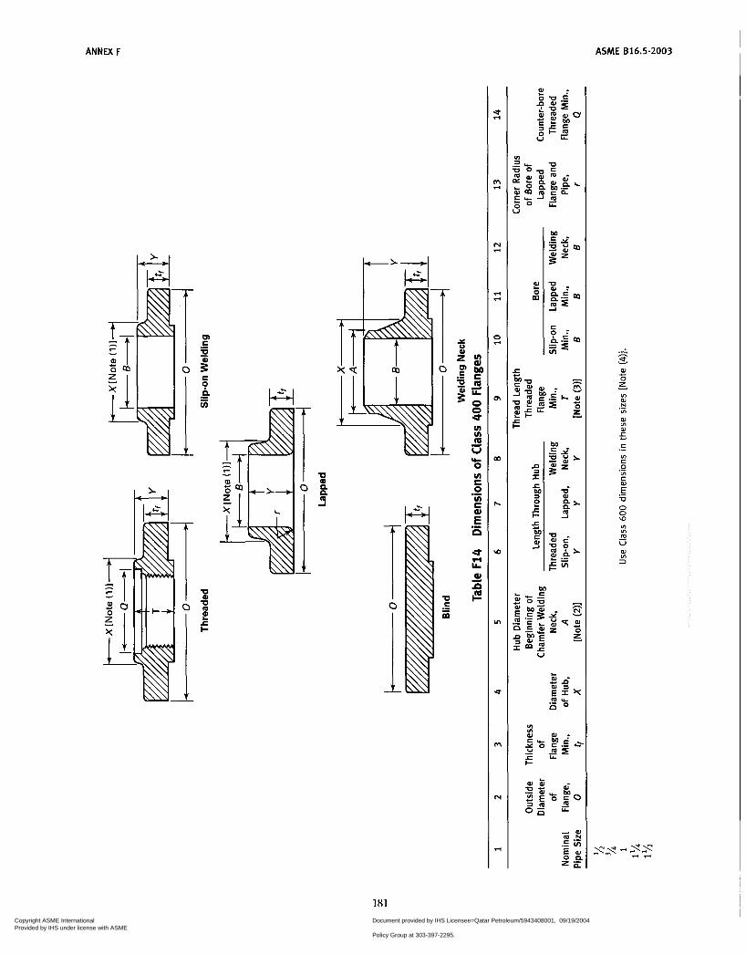
ANNEX F ASME 816.5-2003
U E .- E
ul VI cp V & O ul E O VI c
d
.-
.- E n U w LL 8 ?i cm
t m O
- h
.5 o, O z VI al N
VI
W VI 0)
c
I
.-
5 C .- VI C O VI c .- .- E U O O W VI v1 m U - aJ VI 3
181 Copyright ASME International Provided by IHS under license with ASME
Document provided by IHS Licensee=Qatar Petroleum/5943408001, 09/19/200422:36:17 MDT Questions or comments about this message: please call the DocumentPolicy Group at 303-397-2295.
--```,,`,``,,,,`,,``````,,``,`-`-`,,`,,`,`,,`---
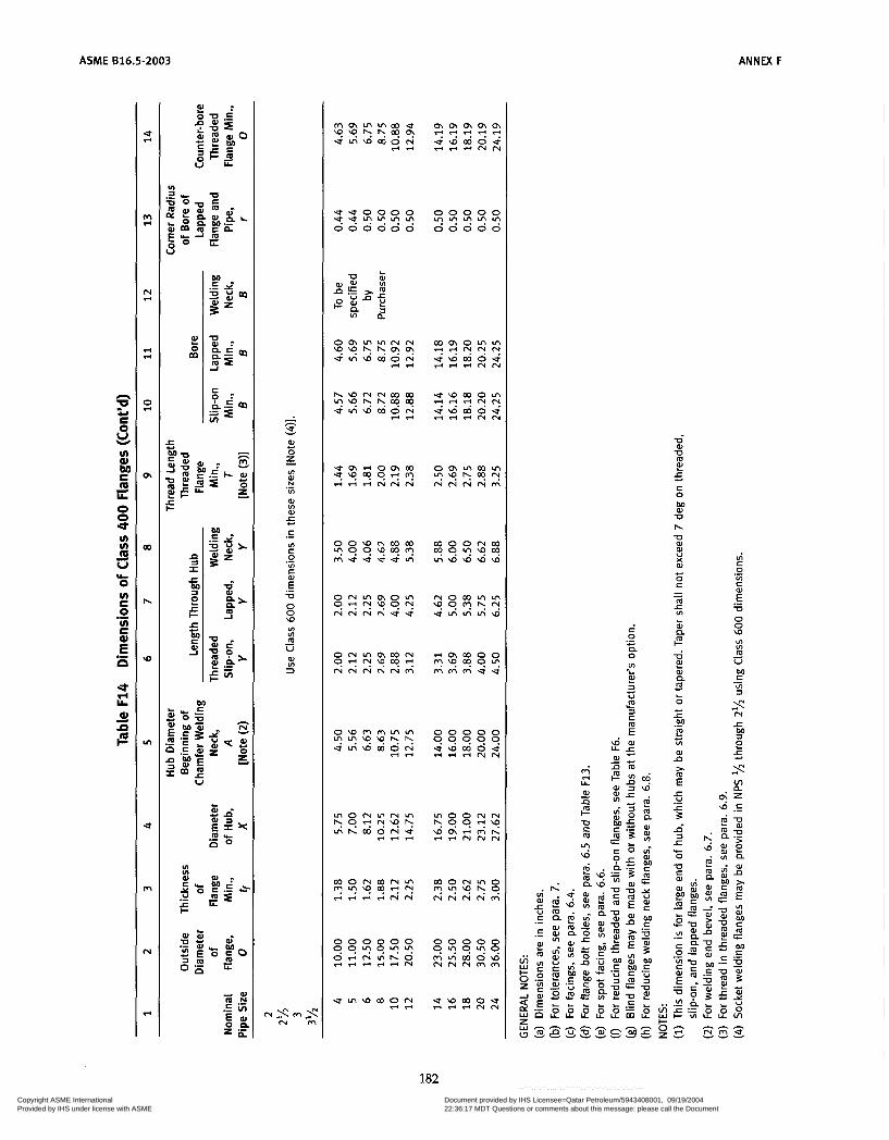
ACME 616.5-2003 ANNEX F
182 Copyright ASME International Provided by IHS under license with ASME
Document provided by IHS Licensee=Qatar Petroleum/5943408001, 09/19/200422:36:17 MDT Questions or comments about this message: please call the DocumentPolicy Group at 303-397-2295.
--```,,`,``,,,,`,,``````,,``,`-`-`,,`,,`,`,,`---

ANNEX F
CLASS 600 PIPE FLANGES AND FLANGED FITTINGS
ASME 816.5-2003
Point height [Note (1)l
Flange Stud Bolt With Nuts
Table F15 Templates for Drilling Class 600 Flanges 1 2 3 4 5 6 7 8 9
Outside Diameter
Nominal of Flange, Pipe Size O
Drilling [Notes (2), (3)J
Diameter of Bolt Circle, Diameter of Number of Diameter of
W Bolt Holes Bolts Bolts
lh 3.75 3/i 4.62 1 4.88
1% 5.25 1% 6.12
2.62 'h 4 lh 3.25 3/i 4 '/a 3.50 3/i 4 'h 3.88 3/i 4 'A 4.50 'h 4 3/i
Length of Bolts, 1
[Notes (11, (411
0.25 in. Tongue and Groove Ring Joint
3.00 2.75 3.00 3.50 3.25 3.50 3.50 3.25 3.50 3.75 3.50 3.75 4.25 4.00 4.25
Raised Face Male and Female/
2 6.50 5.00 % 8 % 4.25 4.00 4.25
3 8.25 6.62 % 8 3L 5.00 4.75 5.00 3 % 9.00 7.25 1 8 'h 5.50 5.25 5.50
2% 7.50 5.88 'h a 3L 4.75 4.50 4.75
4 10.75 8.50 1 8 7h 5.75 5.50 5.75
5 13.00 10.50 1 'h 8 1 6.50 6.25 6.50 6 14.00 11.50 1 'h 12 1 6.75 6.50 6.75
10 20.00 17.00 1 16 1 'Aí 8.50 8.25 8.50 1 2 22.00 19.25 1 20 1 'A 8.75 8.50 8.75
14 23.75 20.75 1% 20 1 9.25 9.00 9.25
18 29.25 25.75 1 3/i 20 1% 10.75 10.50 10.75 20 32.00 28.50 1 3~ 24 1% 11.25 11.00 11.50 24 37.00 33.00 2 24 1% 13.00 12.75 13.25
8 16.50 13.75 1 % 12 1 'h 7.50 7.25 7.75
16 27.00 23.75 1% 20 1% 10.00 9.75 10.00
GENERAL NOTES: (a) Dimensions are in inches. (b) For other dimensions, see Table F16.
NOTES: (1) Length of stud bolt does not include the height of the points. See para. 6.10.2. (2) For flange bolt hole, see para. 6.5. (3) For spot facing, see para. 6.6. (4) Bolt lengths not shown in table may be determined in accordance with Annex D. See para. 6.10.2.
183 Copyright ASME International Provided by IHS under license with ASME
Document provided by IHS Licensee=Qatar Petroleum/5943408001, 09/19/200422:36:17 MDT Questions or comments about this message: please call the DocumentPolicy Group at 303-397-2295.
--```,,`,``,,,,`,,``````,,``,`-`-`,,`,,`,`,,`---
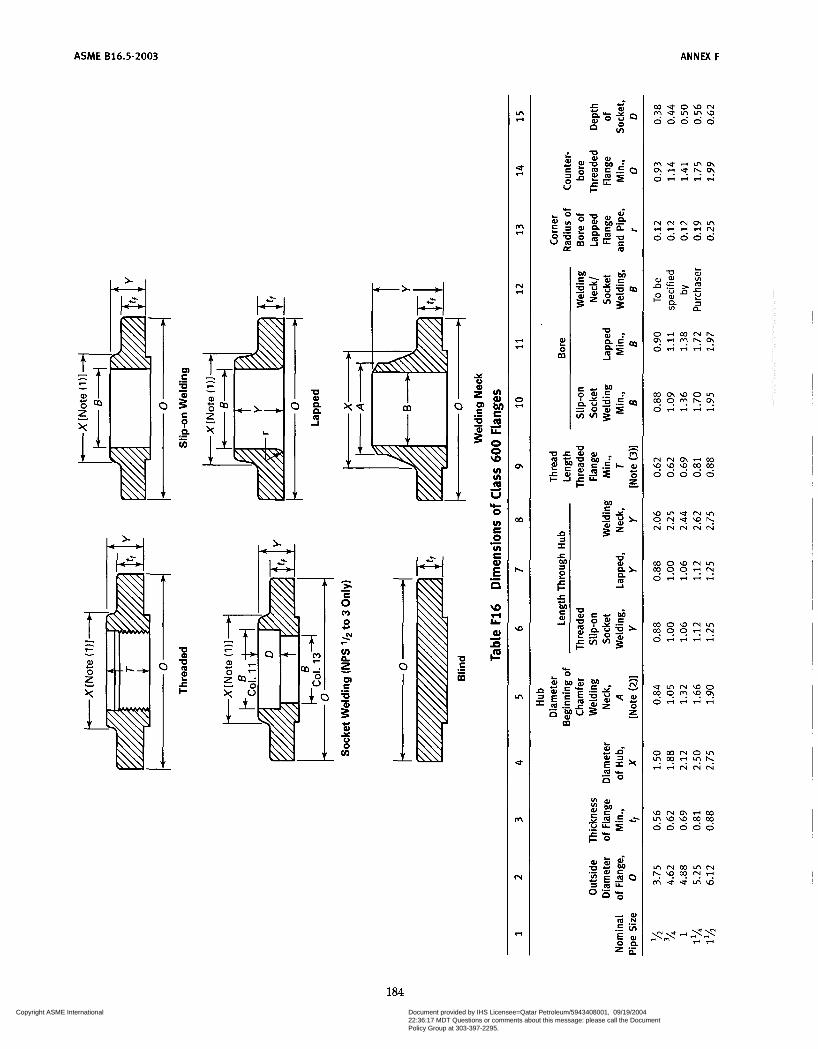
ASME 816.5-2003
E rn
184 Copyright ASME International Provided by IHS under license with ASME
Document provided by IHS Licensee=Qatar Petroleum/5943408001, 09/19/200422:36:17 MDT Questions or comments about this message: please call the DocumentPolicy Group at 303-397-2295.
--```,,`,``,,,,`,,``````,,``,`-`-`,,`,,`,`,,`---

ANNEX F ASME 616.5-2003
c
e, P E O
u) aJ
m LL
O O \o u) u) m
E d
5 ic O u) E O u) C a3
.- E ci .- \o H L al = cm
- s - 4 c o c o . u .u0000 0 0 0 0 0 0 0 0 0 0 0 0 0 0 0 0 0 0 0 0 ' ? < ? < ? ' ? U T . 5 " " ? ? L ? L ? V !
U
U m 2 5 8 O
M al U h
U o)
X o)
O G
m A= VI
o)
u c
- - L
c n im
O 6 v) L
n L
O
Q ._ c
L al
m S * Y
L O
U
185
Copyright ASME International Provided by IHS under license with ASME
Document provided by IHS Licensee=Qatar Petroleum/5943408001, 09/19/200422:36:17 MDT Questions or comments about this message: please call the DocumentPolicy Group at 303-397-2295.
--```,,`,``,,,,`,,``````,,``,`-`-`,,`,,`,`,,`---
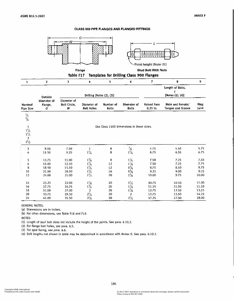
ASME 816.5-2003
CLASS 900 PIPE FLANGES AND FLANGED FI lTINGS
Point height [Note (111
Flange Stud Bolt With Nuts
Table F17 Templates for Drilling Class 900 Flanges
ANNEX F
1 2 3 4 5 6 7 a 9
Length of Bolts, 1
Outside Drilling [Notes (2), (311 [Notes (11, (411
Diameter of Diameter of Nominal Flange, Bolt Circle, Diameter of Number of Diameter of Raised Face Male and Female/ Ring Pipe Size O W Bolt Holes Bolts Bolts 0.25 in. Tongue and Groove Joint
1 Use Class 1500 dimensions in these sizes. ll/i 1%
2% 2
3 9.50 7.50 1 8 '/8 5.75 5.50 5.75 4 11.50 9.25 1% 8 1 '/8 6.75 6.50 6.75
5 13.75 11.00 1 58 8 1% 7.50 7.25 7.50
8 18.50 15.50 1 l/2 12 1 8.75 8.50 8.75 10 21.50 18.50 1% 16 1 9.25 9.00 9.25
6 15.00 12.50 1 l/i 12 11/8 7.50 7.25 7.75
12 24.00 21.00 1 % 20 1 10.00 9.75 10.00
14 25.25 22.00 158 20 1% 10.75 10.50 11 .o0 16 27.75 24.25 1 3~ 20 158 11.25 11 .o0 11.50 18 31.00 27.00 2 20 1 7~ 12.75 12.50 13.25 20 33.75 29.50 2 '/8 20 2 13.75 13.50 14.25 24 41.00 35.50 27á 20 2% 17.25 17.00 18.00
GENERAL NOTES: (a) Dimensions are in inches. (b) For other dimensions, see Table F18 and F19. NOTES: (i) Length of stud bolt does not include the height of the points. See para. 6.10.2. (2) For flange bolt holes, see para. 6.5. (3) For spot facing, see para. 6.6. (4) Bolt lengths not shown in table may be determined in accordance with Annex D. See para. 6.10.2.
186 Copyright ASME International Provided by IHS under license with ASME
Document provided by IHS Licensee=Qatar Petroleum/5943408001, 09/19/200422:36:17 MDT Questions or comments about this message: please call the DocumentPolicy Group at 303-397-2295.
--```,,`,``,,,,`,,``````,,``,`-`-`,,`,,`,`,,`---

ANNEX F ASME 816.5-2003
w
UI v) m U
O v) C O v) e
d
b
.-
.- E n
- h s W O z VI 0) N
VI
aJ VI aJ
c
I
.-
5 r .- VI c O VI c .- .- E U O :: VI VI m U - W VI 3
187
Copyright ASME International Provided by IHS under license with ASME
Document provided by IHS Licensee=Qatar Petroleum/5943408001, 09/19/200422:36:17 MDT Questions or comments about this message: please call the DocumentPolicy Group at 303-397-2295.
--```,,`,``,,,,`,,``````,,``,`-`-`,,`,,`,`,,`---

ASME 816.5-2003 ANNEX F
b O v) E O v) E .- .- E a
s
m l-4
N l-4
l-4 l-4
s
I
OI
W
h
W
In
U
m
N
l-4
188 Copyright ASME International Provided by IHS under license with ASME
Document provided by IHS Licensee=Qatar Petroleum/5943408001, 09/19/200422:36:17 MDT Questions or comments about this message: please call the DocumentPolicy Group at 303-397-2295.
--```,,`,``,,,,`,,``````,,``,`-`-`,,`,,`,`,,`---

ANNE F ASME 816.5-2003
CLASS 1500 PIPE FLANGES
I - ! A / . H I
Point height [Note ( I ) ]
Flange Stud Bolt With Nuts
Table F19 Templates for Drilling Class 1500 Flanges
1 2 3 4 5 6 7 8 9
Length of Bolts, 1
Outside Drilling [Notes (2), (3)] [Notes (11, (411 Diameter of Diameter of
Nominal Flange, Bolt Circle, Diameter of Number of Diameter of Raised Face Male and Female/ Pipe Size O W Bolt Holes Bolts Bolts 0.25 in. Tongue and Groove Ring Joint
lh 4.75 3.25 % 4 3/4 4.25 4.00 4.25 % 5.12 3.50 % 4 % 4.50 4.25 4.50 1 5.88 4.00 1 4 % 5.00 4.75 5.00
1 l/4 6.25 4.38 1 4 % 5.00 4.75 5.00
1 lh 7.00 4.88 1% 4 1 5.50 5.25 5.50
2% 9.62 7.50 1 '/8 8 1 6.25 6.00 6.25 3 10.50 8.00 1% 8 11/8 7.00 6.75 7.00
2 8.50 6.50 1 8 7/8 5.75 5.50 5.75
4 12.25 9.50 1 8 1 l/4 7.75 7.50 7.75
5 14.75 11.50 1% 8 1 lh 9.75 9.50 9.75 6 15.50 12.50 1% 12 1% 10.25 10.00 10.50 8 19.00 15.50 1 3/4 12 1% 11.50 11.25 12.75 10 23.00 19.00 2 12 1% 13.25 13.00 13.50 12 26.50 22.50 2% 16 2 14.75 14.50 15.25
14 29.50 25.00 2% 16 2% 16.00 15.75 16.75 16 32.50 27.75 258 16 2% 17.50 17.25 18.50 18 36.00 30.50 2'/8 16 2% 19.50 19.25 20.75 20 38.75 32.75 3% 16 3 21.25 21.00 22.25 24 46.00 39.00 35/8 16 3% 24.25 24.00 25.50
GENERAL NOTES: (a) Dimensions are in inches. (b) For other dimensions, see Table F20. NOTES: (1) Length of stud bolt does not include the height of the points. See para. 6.10.2. (2) For flange bolt holes, see para. 6.5. (3) For spot facing, see para. 6.6. (4) Bolt lengths not shown in Table determined in accordance with Annex D. See para. 6.10.2.
189 Copyright ASME International Provided by IHS under license with ASME
Document provided by IHS Licensee=Qatar Petroleum/5943408001, 09/19/200422:36:17 MDT Questions or comments about this message: please call the DocumentPolicy Group at 303-397-2295.
--```,,`,``,,,,`,,``````,,``,`-`-`,,`,,`,`,,`---

ASME 616.5-2003
L1-l I > - 8 < r lu O +,
< c
2 z o ul C .- 5 c al u O v)
FI
VI VI fa U
O VI c O VI r
L
k
.-
.- E a O N LL aJ li F
190 Copyright ASME International Provided by IHS under license with ASME
Document provided by IHS Licensee=Qatar Petroleum/5943408001, 09/19/200422:36:17 MDT Questions or comments about this message: please call the DocumentPolicy Group at 303-397-2295.
--```,,`,``,,,,`,,``````,,``,`-`-`,,`,,`,`,,`---

ASME B16.5-2003
m m m 0 0 0 . . u ? ? \ : : . . . . . . . . . . . . . . . . . . . .
. . . . . . . . . . . . . . . . . . . . . . . . . . . . . .
* o 0 0 0 0 0 0 0 0 u L ? L ? L ? .
0 0 0 0 0
0 0 0 0 0 L ? L ? L ? L ? .
o-
LI 5
z
W o m
c O
o h o a, a,
W
O c
m -c VI
W
:: Y
- - L
a lm u LI n 0)
m
O
bo
+ L
E e ._ I VI
W a z E
. . . . . . . . . . . . . . . . . . . . . . . . . v) W bi: e m LL
O O Ln m v) v) m U
O
d
d
b
. .
m o m . . NL?. : :
. . . . . . . . . . . . . . . . . . . . . . . . . . . . . .
r i r ie
. . . . . . . . . . . . . . . . . . . . . . . . .
0 0 0 0 0
u \ D m o u e r r e "
9 9 9 9 9
o o o m o .?9\9 O \ N W W W m r n m m u
, \ " m , \ " m u r i m
191 Copyright ASME International Provided by IHS under license with ASME
Document provided by IHS Licensee=Qatar Petroleum/5943408001, 09/19/200422:36:17 MDT Questions or comments about this message: please call the DocumentPolicy Group at 303-397-2295.
--```,,`,``,,,,`,,``````,,``,`-`-`,,`,,`,`,,`---
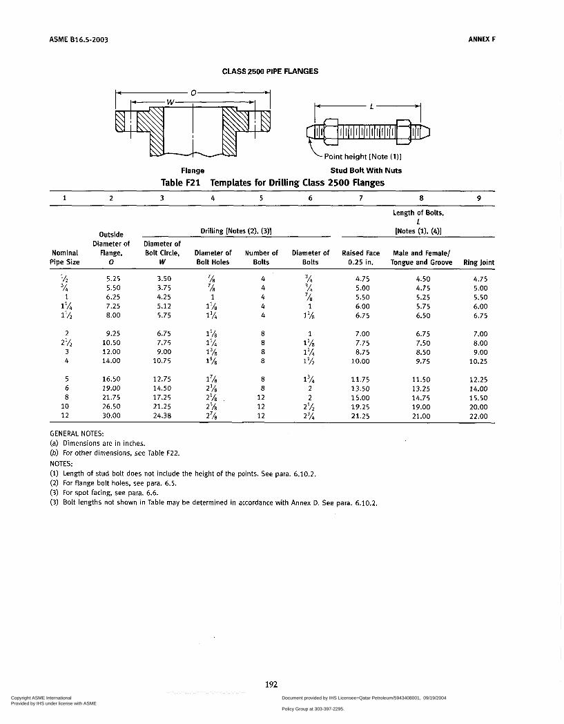
ASME 816.5-2003 ANNEX F
CLASS 2500 PIPE FLANGES
Point height [Note (111
Flange Stud Bolt With Nuts
Table F21 Templates for Drilling Class 2500 Flanges
1 2 3 4 5 6 7 8 9
Outside Diameter of
Nominal Flange, Pipe Size O
Drilling [Notes f21. f3N ~
Diameter of Bolt Circle, Diameter of Number of Diameter of
W Bolt Holes Bolts Bolts
IA 5.25 54 5.50 1 6.25
1 7.25 1% 8.00
3.50 58 4 3L 3.75 58 4 3L 4.25 1 4 58 5.12 l'A7 4 1 5.75 1% 4 1 'A7
Length of Bolts, 1
[Notes (11, (411
Raised Face Male and Female/ 0.25 in. Tongue and Groove Ring Joint
4.75 4.50 4.75 5.00 4.75 5.00 5.50 5.25 5.50 6.00 5.75 6.00 6.75 6.50 6.75
2 9.25 6.75 1 '/É 8 1 7.00 6.75 7.00 2% 10.50 7.75 1% 8 1 'A7 7.75 7.50 8.00
3 12.00 9.00 1 ' ~ 7 8 1% 8.75 8.50 9.00 4 14.00 10.75 1 ' ~ 7 8 1% 10.00 9.75 10.25
5 16.50 12.75 1 'A7 8 1 3~ 11.75 11.50 12.25 6 19.00 14.50 2% 8 2 13.50 13.25 14.00 8 21.75 17.25 2IA7 12 2 15.00 14.75 15.50
10 26.50 21.25 2% 12 2% 19.25 19.00 20.00 1 2 30.00 24.38 2'h 1 2 2% 21.25 21.00 22.00
GENERAL NOTES: (a) Dimensions are in inches. (b) For other dimensions, see Table F22. NOTES: (i) Length of stud bolt does not include the height of the points. See para. 6.10.2. (2) For flange bolt holes, see para. 6.5. (3) For spot facing, see para. 6.6. (3) Bolt lengths not shown in Table may be determined in accordance with Annex D. See para. 6.10.2.
192 Copyright ASME International Provided by IHS under license with ASME
Document provided by IHS Licensee=Qatar Petroleum/5943408001, 09/19/200422:36:17 MDT Questions or comments about this message: please call the DocumentPolicy Group at 303-397-2295.
--```,,`,``,,,,`,,``````,,``,`-`-`,,`,,`,`,,`---
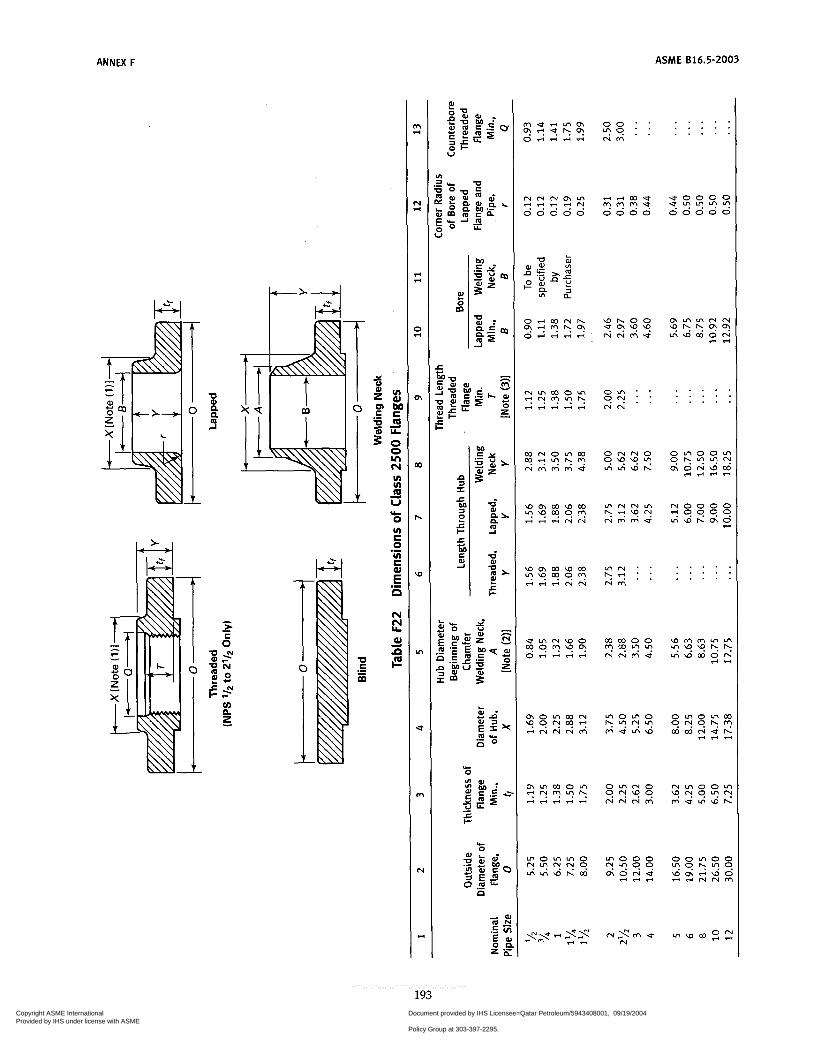
ANNEX F ASME 616.5-2003
ñ m , E - z I
U a l a U M m r 2 2 c
L O W à J -E .- c M U al m
L
I G a l a
5? o rnorno Z $ X ?
O r n N O
193 Copyright ASME International Provided by IHS under license with ASME
Document provided by IHS Licensee=Qatar Petroleum/5943408001, 09/19/200422:36:17 MDT Questions or comments about this message: please call the DocumentPolicy Group at 303-397-2295.
--```,,`,``,,,,`,,``````,,``,`-`-`,,`,,`,`,,`---

ASME 616.5-2003 ANNW F
Notes to Table F22 GENERAL NOTES: (a) Dimensions are in inches. (b) For tolerances, see para. 7 . (c) For facings, see para. 6.4. (d) For flange bolt holes, see para. 6.5 and Table F21. (e) For spot facing, see para. 6.6. (9 For reducing threaded and slip-on flanges, see Table F6. (g) Blind flanges may be made with or without hubs at the manufacturer’s option. (h) For reducing welding neck flanges, see para. 6.8. NOTES: (1) This dimension is For large end of hub, which may be straight or tapered. Taper shall not exceed 7 deg on threaded,
slip-on, socket-welding, and lapped flanges. (2) For welding end bevel, see para. 6.7. (3) For threads in threaded flanges, see para. 6.9.
194 Copyright ASME International Provided by IHS under license with ASME
Document provided by IHS Licensee=Qatar Petroleum/5943408001, 09/19/200422:36:17 MDT Questions or comments about this message: please call the DocumentPolicy Group at 303-397-2295.
--```,,`,``,,,,`,,``````,,``,`-`-`,,`,,`,`,,`---
ASME 816.5-2003
ANNEX G DIMENSIONS OF CLASSES 400,600,900,1500, AND 2500
FLANGED FITTINGS IN U.S. CUSTOMARY UNITS
This Annex is not a mandatory annex of B16.5-2003, and is placed after the main text for information.
This Annex contains Tables G1 through G5.
195 Copyright ASME International Provided by IHS under license with ASME
Document provided by IHS Licensee=Qatar Petroleum/5943408001, 09/19/200422:36:17 MDT Questions or comments about this message: please call the DocumentPolicy Group at 303-397-2295.
--```,,`,``,,,,`,,``````,,``,`-`-`,,`,,`,`,,`---

ASME 816.5-2003 ANNEX G
- h F4 v
W O z I
I
c .- VI
2 W U
I2 U W v)
ai .- m
o P U W
m G
vi 0) N
VI .- 0) VI W
5 c .- VI c O
VI c .-
.- E -a O O u)
VI VI m U -
196 Copyright ASME International Provided by IHS under license with ASME
Document provided by IHS Licensee=Qatar Petroleum/5943408001, 09/19/200422:36:17 MDT Questions or comments about this message: please call the DocumentPolicy Group at 303-397-2295.
--```,,`,``,,,,`,,``````,,``,`-`-`,,`,,`,`,,`---
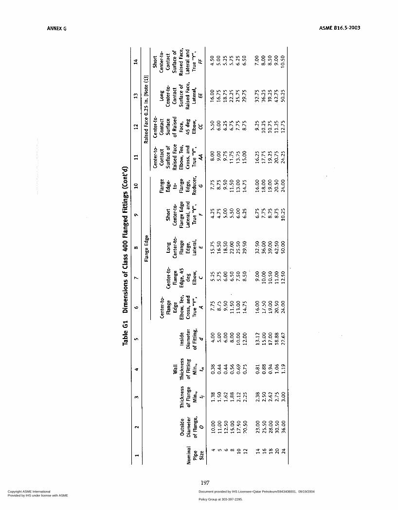
ANNEX G ASME 616.5-2003
n P
Yi O u) E O u) E .- .- E n
o o m m m o
u m m m w \ o L ? 9 N k N "
m u u w n m C?.."?h 0 0 0 0 0 0
I e r i
0 0 0 0 0 9 9 9 " 9 w m c n o u ririri"
m m m m m k k N h N w h m m o
ri
0 0 0 0 0 y z x g m m m u m
u w m o u r i r r r i "
197 Copyright ASME International Provided by IHS under license with ASME
Document provided by IHS Licensee=Qatar Petroleum/5943408001, 09/19/200422:36:17 MDT Questions or comments about this message: please call the DocumentPolicy Group at 303-397-2295.
--```,,`,``,,,,`,,``````,,``,`-`-`,,`,,`,`,,`---
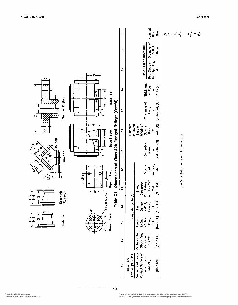
ASME 816.5-2003
m
I+-
f v) I
Q
o u) m
e m
n
E O
P
s U
E
P /-
8 m U
3 O p:
vi W N
LA ._
O O W
al LA
3
198 Copyright ASME International Provided by IHS under license with ASME
Document provided by IHS Licensee=Qatar Petroleum/5943408001, 09/19/200422:36:17 MDT Questions or comments about this message: please call the DocumentPolicy Group at 303-397-2295.
--```,,`,``,,,,`,,``````,,``,`-`-`,,`,,`,`,,`---

ANNEX G ASME 816.5-2003
h 4
b r
U
- - a l m m m al-u- m a l a l c a l % J V I C ; m - O = z z
k- o-- z d V
Copyright ASME International Provided by IHS under license with ASME
Document provided by IHS Licensee=Qatar Petroleum/5943408001, 09/19/200422:36:17 MDT Questions or comments about this message: please call the DocumentPolicy Group at 303-397-2295.
--```,,`,``,,,,`,,``````,,``,`-`-`,,`,,`,`,,`---

ASME B16.5-2003 ANNEX G
P K
- . : c m -I
P 3 U
~ 0 0 0 0 0 ? ? ? ? u ! u u u u u
o m o m o ? k 9 N ? r i r i N N N
o o o m m m w h k m ? ? O ? .
0 0 0 0 0 ? ? O ? ? m m u u u
m o m 0 0 N ? k O ? O r i N U W r i r i r i *r i
m m r i u m NNrnrn-? 0 0 0 0 0
200
Copyright ASME International Provided by IHS under license with ASME
Document provided by IHS Licensee=Qatar Petroleum/5943408001, 09/19/200422:36:17 MDT Questions or comments about this message: please call the DocumentPolicy Group at 303-397-2295.
--```,,`,``,,,,`,,``````,,``,`-`-`,,`,,`,`,,`---

ANNEX G ASME 816.5-2003
0 0 0 0 0
w \ D h w O O 9 " 9 9 u ? z
2
U -I
-I -I
n
n
P
h
W
VI
*
rn
N
c
+ r i + +
0 0 0 0 0 m o o 0 0 " 9 " " " N " 9 " 9 m + u o i + u w m m m r i m m m m m m u u m
0 0 0 0 0 9 9 9 " " o - m r n w + + + r i r i
o o o m o o r i m m u " " 9 h " r i r i r i++
u- O
201
Copyright ASME International Provided by IHS under license with ASME
Document provided by IHS Licensee=Qatar Petroleum/5943408001, 09/19/200422:36:17 MDT Questions or comments about this message: please call the DocumentPolicy Group at 303-397-2295.
--```,,`,``,,,,`,,``````,,``,`-`-`,,`,,`,`,,`---
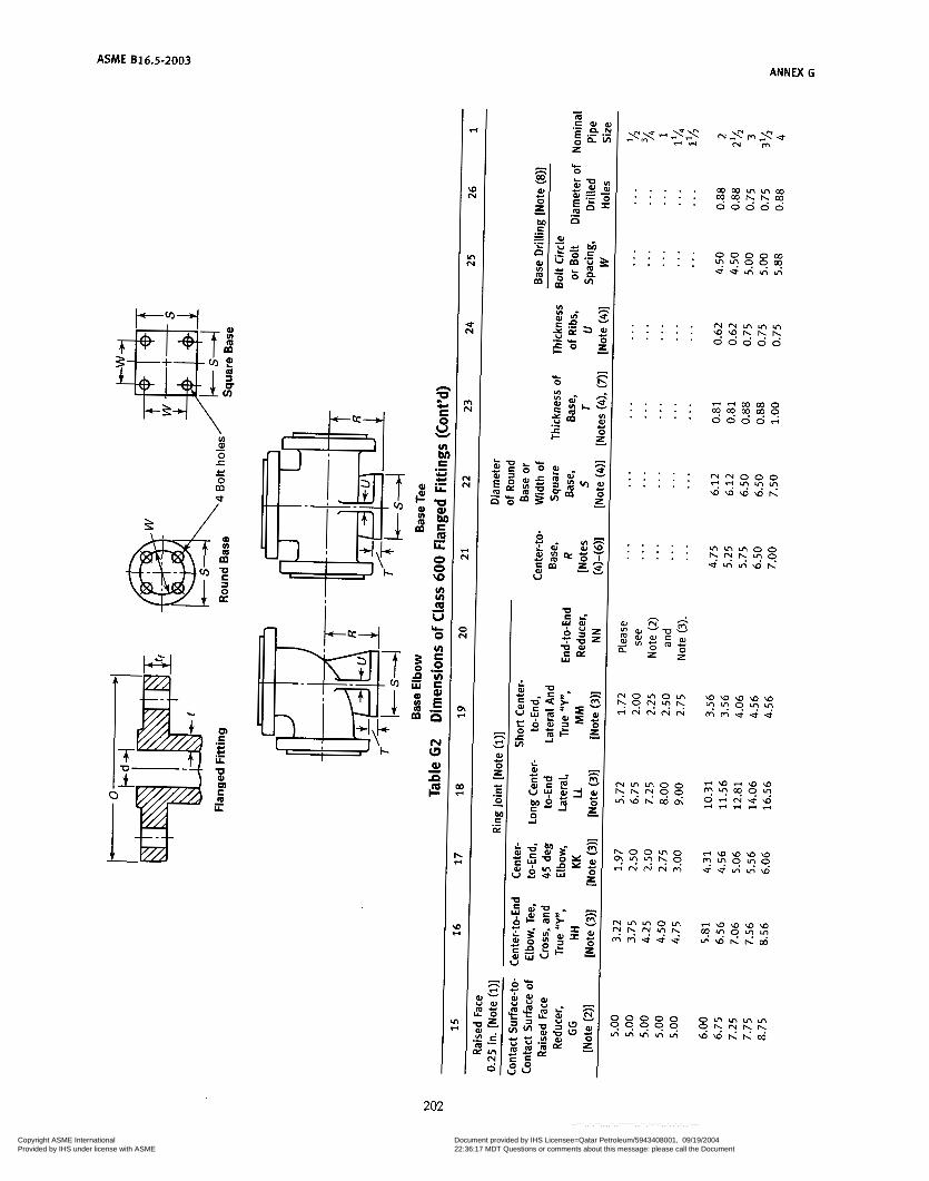
ASME B16.5-2003 ANNEX G
8 m ?! m a U v)
m
v) al O r O
- c - m
al v)
m m
a E O K
7 i
. . . . . . . . . . . . . . .
. . . . . . . . . .
. . . . . . . . . . . . . . .
. . . . . . . . . . . . . . .
. . . . . . . . . . . . . . .
. . . . . . . . . . . . . . .
- - m m 0 m m m m q o o o o r i
" 0 0 0
W W W W h Y ? ? ? ?
202
Copyright ASME International Provided by IHS under license with ASME
Document provided by IHS Licensee=Qatar Petroleum/5943408001, 09/19/200422:36:17 MDT Questions or comments about this message: please call the DocumentPolicy Group at 303-397-2295.
--```,,`,``,,,,`,,``````,,``,`-`-`,,`,,`,`,,`---
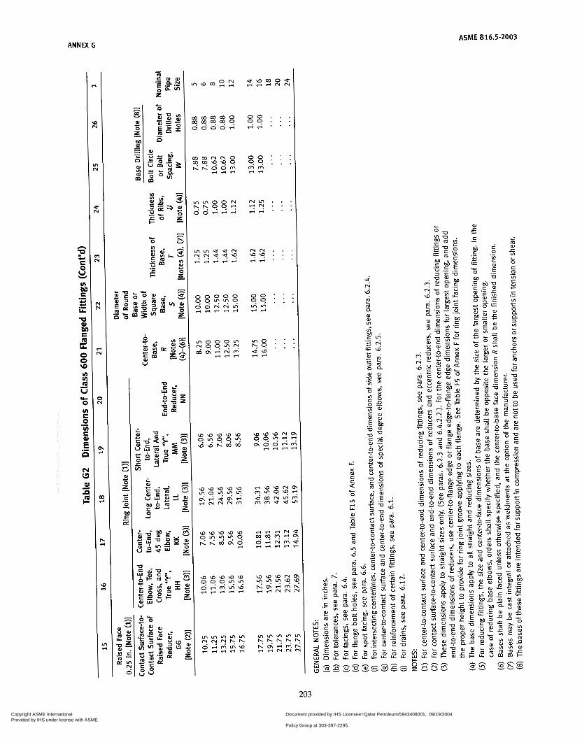
ANNEX C ASME 816.5-2003
- h
w m al O z M
e
I
.- e - .- P m m W u)
U r
Y
u w m o u -.+e"
O O . . . - r i . . . O O . . .
w w w w w w w h m w 9L?99v !
O O . . . 9 9 : : : m m riri
m o . . u w r i d
.9 : :
W W W N i
m o o - 4 - 4
99"T' " - E .!!
M 2
E C C O .- .- - V I
E L o ._ h" u
L: m W
2= VI
O c O VI S W
8
L
.- c
._ 2 O CT Q 3 v)
O
O 1 U c m
L
L
L
P
203
Copyright ASME International Provided by IHS under license with ASME
Document provided by IHS Licensee=Qatar Petroleum/5943408001, 09/19/200422:36:17 MDT Questions or comments about this message: please call the DocumentPolicy Group at 303-397-2295.
--```,,`,``,,,,`,,``````,,``,`-`-`,,`,,`,`,,`---
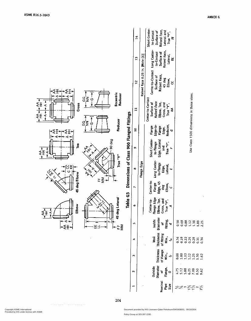
ASME 816.5-2003 ANNEX G
vi W N VI
W VI W
.-
5 .- 8
VI <- O
VI 8 .- .- E" V O O In ri
VI VI m U
0) VI
3
-
204
Copyright ASME International Provided by IHS under license with ASME
Document provided by IHS Licensee=Qatar Petroleum/5943408001, 09/19/200422:36:17 MDT Questions or comments about this message: please call the DocumentPolicy Group at 303-397-2295.
--```,,`,``,,,,`,,``````,,``,`-`-`,,`,,`,`,,`---
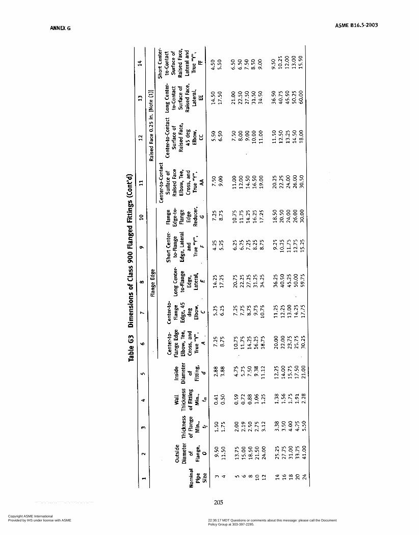
ANNEX C ASME 816.5-2003
0 0 0 0 0 ."u!"? w w ~ m m
o m o m o L?.L?N9 w o m o o m u u r n w
CI
n
E P c,
8 U
u)
E bi:
E .- .- LL U Q) bi: E m LL
O O m u) u) m U
O u) E O u) E
d
d
*
.-
.- E n
m L3 al = im
0 0 0 0 0 " " 0 9 9 w o e w o r i m m m m
m m m r n m N N N N . w w h m m
m w m o m - 4
u w m o u * r i r i m n
Copyright ASME International Provided by IHS under license with ASME
Document provided by IHS Licensee=Qatar Petroleum/5943408001, 09/19/200422:36:17 MDT Questions or comments about this message: please call the DocumentPolicy Group at 303-397-2295.
--```,,`,``,,,,`,,``````,,``,`-`-`,,`,,`,`,,`---

ASME 816.5-2003
I m
B c a
206
- h e Y
al O z c O
c
L - .- .- r E
I c c Y e al O z I
I
e Y
.- VI
O
vi W N VI W v) W
.-
5 c
v) r O
VI c
.-
.-
.- E -o O O m r4
v) VI m U
W VI 3
-
Copyright ASME International Provided by IHS under license with ASME
Document provided by IHS Licensee=Qatar Petroleum/5943408001, 09/19/200422:36:17 MDT Questions or comments about this message: please call the DocumentPolicy Group at 303-397-2295.
--```,,`,``,,,,`,,``````,,``,`-`-`,,`,,`,`,,`---

ANNEX G ASME 616.5-2003
r r
h Y W O z - L
.- E d - .- l ì
W VI
m m
- h e Y
W O z S O
- I - .- T
.- c ai
Y ò õ
c o m o O O . . . w w o O O . . . 004 H e . . .
N N
+ e . . . '9'9 : : :
8 % : : V I V I . . .
VIO $ 5 : : : . . . e e
i m aJ -c
O S O
VI L
VI s=
Y c
.- W
.-
o Q Q 3
O
O -c
m
(A L
L U r
L
,o
ri -7 v)
a m
W
(A
n
vi
e .- U
O L L L
'0 0 . u z h
v N h
v M h
3
207
Copyright ASME International Provided by IHS under license with ASME
Document provided by IHS Licensee=Qatar Petroleum/5943408001, 09/19/200422:36:17 MDT Questions or comments about this message: please call the DocumentPolicy Group at 303-397-2295.
--```,,`,``,,,,`,,``````,,``,`-`-`,,`,,`,`,,`---

ASME 816.5-2003 ANNEX G
u) u)
2 o
tT"
m \
W U
7
c e k
al O z c1
L
E .- L n
2 W U
s U W v)
m Di .-
I
I U W
c m e
C O U O N V I I ? ? ? ? ? 0 0 0 0 0
3 3
208
Copyright ASME International Provided by IHS under license with ASME
Document provided by IHS Licensee=Qatar Petroleum/5943408001, 09/19/200422:36:17 MDT Questions or comments about this message: please call the DocumentPolicy Group at 303-397-2295.
--```,,`,``,,,,`,,``````,,``,`-`-`,,`,,`,`,,`---
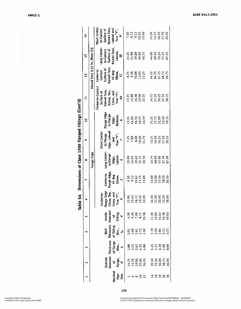
ANNW G ASME B16.5-2003
209
Copyright ASME International Provided by IHS under license with ASME
Document provided by IHS Licensee=Qatar Petroleum/5943408001, 09/19/200422:36:17 MDT Questions or comments about this message: please call the DocumentPolicy Group at 303-397-2295.
--```,,`,``,,,,`,,``````,,``,`-`-`,,`,,`,`,,`---
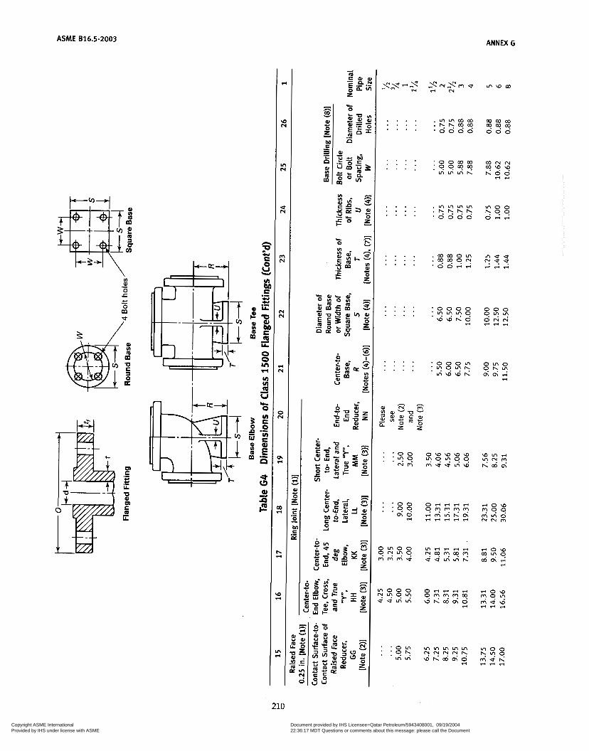
ASME 816.5-2003 ANNEX G
*
u) N
Ln N
N
m N
N N
N
O N
m l-l
2
\ rl
2
n -I
mwCO
L O
. m m C O C O
' O 0 0 0 'hhC909
C O C O C O 2 2 2 . . . . . .
. . . . . . . . .
. . . . . . . . .
. . . . . . . . .
. . . . . . . . .
. . . . . . . . .
. m m m m
' O 0 0 0 . h h h h
m o o 0 - 3 h 9 9 u; m
s a U v)
- O
e m
P /
o w w w w ? 9 ? 9 9 m u u m w
o m 0 0 R?X$
Y ò ö
m o o h ? ? m u h ririri
210
Copyright ASME International Provided by IHS under license with ASME
Document provided by IHS Licensee=Qatar Petroleum/5943408001, 09/19/200422:36:17 MDT Questions or comments about this message: please call the DocumentPolicy Group at 303-397-2295.
--```,,`,``,,,,`,,``````,,``,`-`-`,,`,,`,`,,`---

ANNEX G ASME B16.5-2003
n
E P U
8 2 u
E U U
Y,
U
E
LL
O O rn fl v) v) m U
O VI r O v) c
.- .- c 9
d
&
.-
.- E n U W al ñ im
t-4
N
YI N
U N
m N
N N
t-4 N
O N
oi e
z
h t-4
\o t-4
YI e
i: W
W O z
w
I
I
c 8
m
.- w - .- W VI m
b O
u W r VI
K c W
.-
5 n W
- - m r VI
oc c O VI K .-
.- E
2 c
U
W VI m
c W
S W U
W
Y
5 U K m U-
!E W Q Y)
al VI
2 W
O VI
W S 3 u
5
-
u L F
211
Copyright ASME International Provided by IHS under license with ASME
Document provided by IHS Licensee=Qatar Petroleum/5943408001, 09/19/200422:36:17 MDT Questions or comments about this message: please call the DocumentPolicy Group at 303-397-2295.
--```,,`,``,,,,`,,``````,,``,`-`-`,,`,,`,`,,`---

ASME 616.5-2003 ANNEX G
AA t L HH A
Elbow 45 deg E lbow Tee
F F MM
Cross 45 deg Lateral
Table 65 Dimensions of Class 2500 Flanged Fittings 1 2 3 4 5 6 7 8 9 10
Flange Edge
Outside Diameter
of Nominal Flange, Pipe Size O
lh 5.25 3h 5.50 1 6.25
1% 7.25 1 l/2 8.00
Thickness of Flange
Min., 4
1.19 1.25 1.38 1.50 1.75
Wall Thickness of Fitting
Min., t
0.25 0.28 0.34 0.44 0.50
Inside Diameter
of Fitting,
d
Center-to- Flange Edge, Elbow, Tee, Cross, and True “Y”,
A
Short Center- Center-to- Long Center- to-Flange
Flange Edge, to-Flange Edge, Lateral 45 deg Edge and Elbow, Lateral, True “Y”,
CE E F
Flange Edge-to- Flange Edge,
Reducer, G
0.44 0.56 0.75 1.00 1.12
4.94 5.12 5.81 6.62 7.31
. . . ... ... 3.75 ... ... 4.00 ... . . . 4.50 ... . . .
. . .
. . .
. . .
. . .
2 9.25 2.00 0.62 1.50 8.62 5.50 15.00 5.00 9.00
3 12.00 2.62 0.88 2.25 11.12 7.00 19.50 6.50 11.25 4 14.00 3.00 1.09 2.88 13.00 8.25 22.75 7.50 13 .O0
2% 10.50 2.25 0.75 1.88 9.75 6.00 17.00 5.50 10.00
5 16.50 3.62 1.34 3.62 15.38 9.75 27.00 9.00 15.25 6 19.00 4.25 1.59 4.38 17.75 11.25 31.00 10.25 17.50 8 21.75 5.00 2.06 5.75 19.88 12.50 35.00 11.50 20.00 10 26.50 6.50 2.59 7.25 24.75 15.75 43.00 14.50 25.00 1 2 30.00 7.25 3.03 8.62 27.75 17.50 49.00 16.00 28.50
212
Copyright ASME International Provided by IHS under license with ASME
Document provided by IHS Licensee=Qatar Petroleum/5943408001, 09/19/200422:36:17 MDT Questions or comments about this message: please call the DocumentPolicy Group at 303-397-2295.
--```,,`,``,,,,`,,``````,,``,`-`-`,,`,,`,`,,`---

ANNEX G ASME 816.5-2003
I ’ Flanged Fitt ing Reducer Eccentric Reducer True ”Y”
Table 6 5 Dimensions of Class 2500 Flanged Fittings (Cont’d)
11 12 13 14 15 16 17 18 19 20 1
Raised Face 0.25 in. [Note (l)] Ring Joint [Note (1))
Short Contact Center- Surface-
Center-to- Contact
Surface of Raised Face Elbow, Tee, Cross, and True “Y”,
AA
Center- to-
Contact Surface
of Raised Face 45 deg Elbow,
cc
Long Center-
to- Contact Surface
of Raised Face
Lateral, EE
to- Contact Surface
of Raised Face
Lateral and
True ‘Y”, FF
to- Contact Surface
of Raised Face
Reducer, GG
[Note (211
Center-to- End, Elbow, Short Center- End-to- Tee, Cross, Center-to- Long Center- to- End End and True End, 45 deg to-End Lateral and Reducer,
“Y*, Elbow, Lateral, True “Y”, NN Nominal HH KK LL MM [Notes Pipe
[Note (3)] [Note (311 [Note (311 [Note (3)] (21, (311 Size
... . . . ... ... . . . 5.19 . . . . . . . . . 5.19 lh 5.37 . . . . . . ... . . . 5.19 %
6.87 4.25 ... ... ... 6.94 4.31 ... . . . ... 1% 7.56 4.75 ... ... ... 7.62 4.81 ... . . . ... 1%
... ... ... . . . ... ... ... ... 1 6.08 4.00 . . . . . . 6.06 4.00
8.87 5.75 15.25 5.25 9.50 8.94 5.81 15.31 5.31 ... 2
11.37 7.25 19.75 6.75 11.75 11.50 7.38 19.88 6.88 . . . 3 13.25 8.50 23.00 7.75 13.50 13.44 8.69 23.19 7.94 . . . 4
10.00 6.25 17.25 5.75 10.50 10.12 6.38 17.38 5.88 ... 2%
15.62 10.00 27.25 9.25 15.75 15.88 10.25 27.50 9.50 . . . 5 18.00 11.50 31.25 10.50 18.00 18.25 11.75 31.50 10.75 . . . 6 20.12 12.75 35.25 11.75 20.50 20.44 13.06 35.56 12.06 ... 8 25.00 16.00 43.25 14.75 25.50 25.44 16.44 43.69 15.19 ... 10 28.00 17.75 49.25 16.25 29.00 28.44 18.19 , 49.69 16.62 ... 12
GENERAL NOTES: (a) Dimensions are in inches. (b) For tolerances, see para. 7. (c) For facings, see para. 6.4. (d) For flange bolt holes, see para 6.5 and Table F21 of Annex F.
(e) For spot facing, see para. 6.6 (9 For intersecting centerlines, center-to-contact surface, and center-to-end dimensions of side outlet fittings, see para.
6.2.4. (9) For center-to-contact surface and center-to-end dimensions of special degree elbows, see para. 6.2.5. (h) For reinforcement of certain fittings, see para. 6.1. (i) For drains, see para. 6.12.
NOTES: (I) For center-to-contact surface and center-to-end dimensions of reducing fittings, see para. 6.2.3. (2) For contact surface-to-contact surface and end-to-end dimensions of reducers and eccentric reducers, see para. 6.2.3. (3) These dimensions apply to straight sizes only (See paras. 6.2.3 and 6.4.2.2). For the center-to-end dimensions of reduc-
ing fittings or end-to-end dimensions of reducers, use center-to-flange edge or flange edge-to-flange edge dimensions for largest opening, and add the proper height to provide for ring joint groove applying to each flange. See Table F5 of Annex F for ring joint facing dimensions.
213
Copyright ASME International Provided by IHS under license with ASME
Document provided by IHS Licensee=Qatar Petroleum/5943408001, 09/19/200422:36:17 MDT Questions or comments about this message: please call the DocumentPolicy Group at 303-397-2295.
--```,,`,``,,,,`,,``````,,``,`-`-`,,`,,`,`,,`---

ASME 816.5-2003
ANNEX H REFERENCESI
H1 GENERA H3 ASTM PUBLICATION
The following is a list of standards and specifications referenced in this Standard, showing the year of approval. Products covered by each ASTM specification are listed for convenience. (See specifications for exact titles and detailed contents.)
H2 ASME PUBLICATIONS
ACME B1.l-1989 (R2001), Unified Inch Screw Threads
ACME 81.20.1-1983 (R2001), Pipe Threads, General Pur-
ACME B16.20-1998, Metallic Gaskets for Pipe Flanges-
ACME B16.21-1992, Nonmetallic Flat Gaskets for Pipe
ACME B16.25-1997, Buttwelding Ends ACME B16.34-2002, Valve-Flanged, Threaded, and Weld-
ACME B18.2.1-1996, Square and Hex Bolts and Screws-
ACME B18.2.2-1987 (R1999), Square and Hex Nuts (Inch
ACME PCC-1-2000, Guidelines for Pressure Boundary
ACME B36.10M-2000, Welded and Seamless Wrought
ACME B46.1-2002, Surface Texture (Surface Roughness,
(UN and UNR Thread Form)
pose (Inch)
Ring Joint, Sprial-Wound and Jacketed
Flanges
ing End
Inch Series
Series)
Bolted Flange Joint Assembly
Steel Pipe
Waviness, and Lay)
H2.1 ASME Boiler and Pressure Vessel Code, 2001
Section I, Power Boilers Section II, Materials Section III, Rules for Construction of Nuclear Power
Plant Components Section VIII, Div. 1 and 2, Pressure Vessels Section IX, Welding and Brazing Qualifications Publisher: The American Society of Mechanical Engi-
neers (ACME International) Three Park Ave, New York, NY 10016-5990; ACME Order Department: 22 Law Drive, Box 2300, Fairfield, NJ 07007-2300
Edition (Including Addenda through 2002)
* This Annex is an integral part of ASME 816.5-2003, and is placed after the main text for convenience.
A 105-2001, Carbon Steel Forgings for Piping Compo- nents
A 106-1999e1, Seamless Carbon Steel Pipe for High-Tem- perature Service
A 182-2001e1, Forged or Rolled Alloy-Steel Pipe Flanges, Forged Fittings, and Valves and Parts for High Tem- perature Service
A 193-200113, Alloy-Steel and Stainless Steel Bolting Materials for High-Temperature Service
A 194-2001a, Carbon and Alloy Steel Nuts for Bolts for High-pressure and High-Temperature Service, or Both
A 203-1997, Pressure Vessel Plates, Alloy Steel, Nickel A 204-1993 (R1999), Pressure Vessel Plates, Alloy Steel,
Molybdenum A 216-1993 (1998), Steel Castings, Carbon, Suitable for
Fusion Welding, for High-Temperature Service A 217-2002, Steel Castings, Martensitic Stainless and
Alloy, for Pressure Containing Parts, Suitable for High-Temperature Service
A 240-2002, Chromium and Chromium-Nickel Stainless Steel Plate, Sheet, and Strip for Pressure Vessels and for General Applications
A 307-2000, Carbon Steel Bolts and Studs, 60,000 psi Tensile Strength
A 320-2001, Alloy/Steel Bolting Materials for Low-Tem- perature Service
A 350-2OOOc Carbon and Low-Alloy Steel Forgings, Requiring Notch Toughness Testing for Piping Com- ponents
A 351-2000, Castings, Austenitic, Austenitic-Ferritic (Duplex), for Pressure Containing Parts
A 352-1993 (R1998), Steel Castings, Ferritic and Marten- sitic, for Pressure-Containing Parts, Suitable for Low- Temperature Service
A 354-2001, Quenched and Tempered Alloy Steel Bolts, Studs and Other Externally Threaded Fasteners
A 387-1999e1, Pressure Vessel Plates, Alloy Steel, Chro- mium-Mol ybdenum
A449-2000, Quenched and Tempered Steel Bolts and Studs
A 453-2000e1, High-Temperature Bolting Materials, with Expansion Coefficients Comparable to Austenitic Stainless Steels
A 515-2001, Pressure Vessel Plates, Carbon Steel, for Intermediate- and Higher-Temperature Service
A 516-2001, Pressure Vessel Plates, Carbon Steel, For Moderated- and Lower-Temperature Service
214
Copyright ASME International Provided by IHS under license with ASME
Document provided by IHS Licensee=Qatar Petroleum/5943408001, 09/19/200422:36:17 MDT Questions or comments about this message: please call the DocumentPolicy Group at 303-397-2295.
--```,,`,``,,,,`,,``````,,``,`-`-`,,`,,`,`,,`---
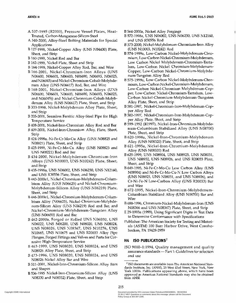
ANNEX H ASME B16.5-2003
A 537-1995 (R2000), Pressure Vessel Plates, Heat-
A 540-2000, Alloy-Steel Bolting Materials for Special
B 127-1998, Nickel-Copper Alloy (UNS N04400) Plate,
B 160-1999, Nickel Rod and Bar B 162-1999, Nickel Plate, Sheet and Strip B 164-1998, Nickel-Copper Alloy Rod, Bar, and Wire B 166-2001, Nickel-Chromium-Iron Alloys (UNS
N06600, N06601, N06603, N06690, N06693, N06025, and N06045) and Nickel-Chromium-Cobalt-Molybde- num Alloy (UNS N06617) Rod, Bar, and Wire
B 168-2001, Nickel-Chromium-Iron Alloys (UNS N06600, N06601, N06603, N06690, N06693, N06025, and N06045)) and Nickel-Chronnium-Cobalt-Molyb- denum Alloy (UNS N06617) Plate, Sheet, and Strip
B 333-1998, Nickel-Molybdenum Alloy Plate, Sheet, and Strip
B 335-2001, Seamless Ferritic Alloy-Steel Pipe for High Temperature Service
B 408-2001, Nickel-Iron-Chromium Alloy Rod and Bar B 409-2001, Nickel-Iron-Chromium Alloy, Plate, Sheet,
Strip B 424-1998a, Ni-Fe-Cr-Mo-Cu Alloy (UNS NO8825 and
N08821) Plate, Sheet, and Strip B 425-1999, Ni-Fe-Cr-Mo-Cu Alloy (UNS NO8825 and
UNS N08221) Rod and Bar B 434-2000, Nickel-Molybdenum-Chromium-Iron
Alloys (UNS N10003, UNS N10242) Plate, Sheet, and Strip
B 435-1998a, UNS N06002, UNS N06230, UNS N12160, and UNS R30556 Plate, Sheet, and Strip
B 443-2000e1, Nickel-Chromium-Molybdenum-Colum- bium Alloy (UNS N06625) and Nickel-Chromium- Molybdenum-Silicon Alloy (UNS N06219) Plate, Sheet, and Strip
B 446-2000e1, Nickel-Chromium-Molybdenum-Colum- bium Alloy (N06625), Nickel-Chromium-Molybde- num-Silicon Alloy (UNS N06219) Rod and Bar, and Nickel-Chromium-Molybdenum-Tungsten Alloy (UNS N06650) Rod and Bar
B 462-2000a, Forged or Rolled UNS N06030, UNS N06022, UNS N06200, UNS N08020, UNS N08024, UNS N08026, UNS N08367, UNS N10276, UNS N10665, UNS N10675 and UNS R20033 Alloy Pipe Flanges, Forged Fittings and Valves and Parts for Cor- rosive High-Temperature Service
B 463-1999, UNS N08020, UNS N08024, and UNS NO8026 Alloy Plate, Sheet, and Strip
B 473-1996, UNS N08020, UNS N08024, and UNS NO8026 Nickel Alloy Bar and Wire
B 51 1-2001, Nickel-Iron-Chromium-Silicon Alloy Bars and Shapes
B 536-1995 Nickel-Iron-Chromium-Silicon Alloy (UNS NO8330 and N08332) Plate, Sheet, and Strip
Treated, Carbon-Manganese-Silicon-Steel
Applications
Sheet, and Strip
B 564-2000a, Nickel Alloy Forgings B 572-1998a, UNS N06002, UNS N06230, UNS N12160,
and UNS R30556 Rod B 573-2000, Nickel-Molybdenum-Chromium-Iron Alloy
(UNS N10003, N10242) Rod B 574-1999a, Low-Carbon Nickel-Molybdenum-Chro-
mium, Low-Carbon Nickel-Chromium-Molybdenum, Low Carbon Nickel Molybdenum-Chromium-Tanta- lum, Low-Carbon Nickel Chromium-Molybdenum- Copper, Low-Carbon Nickel-Chromium-Molybde- num-Tungsten Alloy Rod
B 575-1999a, Low-Carbon Nickel-Molybdenum-Chro- mium, Low-Carbon Nickel-Chromium-Molybdenum, Low-Carbon Nickel-Chromium Molybdenum-Cop- per, Low-Carbon Nickel-Chromium-Tantalum, Low- Carbon Nickel-Chromium-Molybdenum-Tungsten Alloy Plate, Sheet, and Strip
B 581-1997, Nickel-Chromium-Iron-Molybdenum-Cop- per Alloy Rod
B 582-1997, Nickel-Chromium-Iron-Molybdenum-Cop- per Alloy Plate, Sheet, and Strip
B 599-1992 (R1997), Nickel-Iron-Chromium-Molybde- num-Columbium Stabilized Alloy (UNS N08700) Plate, Sheet, and Strip
B 620-1998a, Nickel-Iron-Chromium-Molybdenum Alloy (UNS N08320) Plate, Sheet, and Strip
B 621-1995a, Nickel-Iron-Chromium-Molybdenum Alloy (UNS N08320) Rod
UNS N08932, UNS N08926, and UNS R20033 Plate, Sheet, and Strip
B 649-1995, Ni-Fe-Cr-Mo-Cu Low Carbon Alloy (UNS N08904) and Ni-Fe Cr-Mo-Cu-N Low Carbon Alloys (UNS N08925, UNS N08031, and UNS N08926), and Cr-Ni-Fe-N Low-Carbon Alloy (UNS R20033) Bar and Wire
B 672-1995, Nickel-Iron-Chromium-Molybdenum- Columbium Stabilized Alloy (UNS N08700) Bar and Wire
B 688-1996, Chromium-Nickel-Molybdenum-Iron (UNS NO0366 and UNS N08367) Plate, Sheet, and Strip
E 29-1993a (1999), Using Significant Digits in Test Data to Determine Conformance with Specifications
Publisher: The American Society for Testing and Materi- als (ASTM) 100 Barr Harbor Drive, West Consho- hocken, PA 19428-2959
B 625-1999, UNS N08904, UNS N08925, UNS N08031,
H4 IS0 PUBLICATIONS2
IS0 9000-1:1994, Quality management and quality assurance standards - Part 1: Guidelines for selection and use
IS0 documents are available from The American National Stan- dards Institute, Inc. (ANSI), 25 West 43rd Street, New York, New York 10036. Publications appearing above, which have been approved as American National Standards may also be obtained from ANSI.
215 Copyright ASME International Provided by IHS under license with ASME
Document provided by IHS Licensee=Qatar Petroleum/5943408001, 09/19/200422:36:17 MDT Questions or comments about this message: please call the DocumentPolicy Group at 303-397-2295.
--```,,`,``,,,,`,,``````,,``,`-`-`,,`,,`,`,,`---
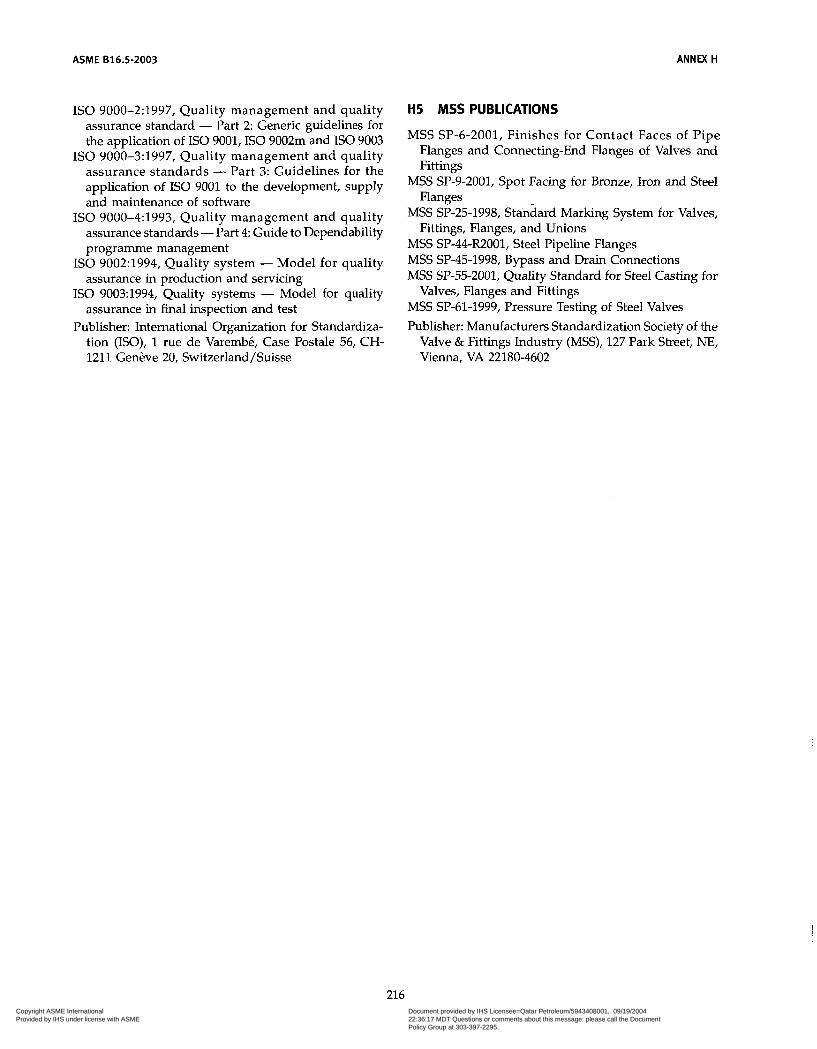
ASME 816.5-2003 ANNEX H
IS0 9000-2:1997, Quality management and quality assurance standard - Part 2: Generic guidelines for the application of IS0 9001, IS0 9002m and IS0 9003
IS0 9000-3:1997, Quality management and quality assurance standards - Part 3: Guidelines for the application of IS0 9001 to the development, supply and maintenance of software
IS0 9000-4:1993, Quality management and quality assurance standards - Part 4: Guide to Dependability programme management
IS0 9002:1994, Quality system - Model for quality assurance in production and servicing
IS0 9003:1994, Quality systems - Model for quality assurance in final inspection and test
Publisher: International Organization for Standardiza- tion (ISO), 1 rue de Varembé, Case Postale 56, CH- 1211 Genève 20, Switzerland/Suisse
H5 MSS PUBLICATIONS
MSS SP-6-2001, Finishes for Contact Faces of Pipe Flanges and Connecting-End Flanges of Valves and Fittings
MSS SP-9-2001, Spot Facing for Bronze, Iron and Steel Flanges
MSS SP-25-1998, Standard Marking System for Valves, Fittings, Flanges, and Unions
MSS SP-44-R2001, Steel Pipeline Flanges MSS SP-45-1998, Bypass and Drain Connections MSS SP-55-2001, Quality Standard for Steel Casting for
MSS SP-61-1999, Pressure Testing of Steel Valves Publisher: Manufacturers Standardization Society of the
Valve & Fittings Industry (MSS), 127 Park Street, NE, Vienna, VA 22180-4602
Valves, Flanges and Fittings
216 Copyright ASME International Provided by IHS under license with ASME
Document provided by IHS Licensee=Qatar Petroleum/5943408001, 09/19/200422:36:17 MDT Questions or comments about this message: please call the DocumentPolicy Group at 303-397-2295.
--```,,`,``,,,,`,,``````,,``,`-`-`,,`,,`,`,,`---
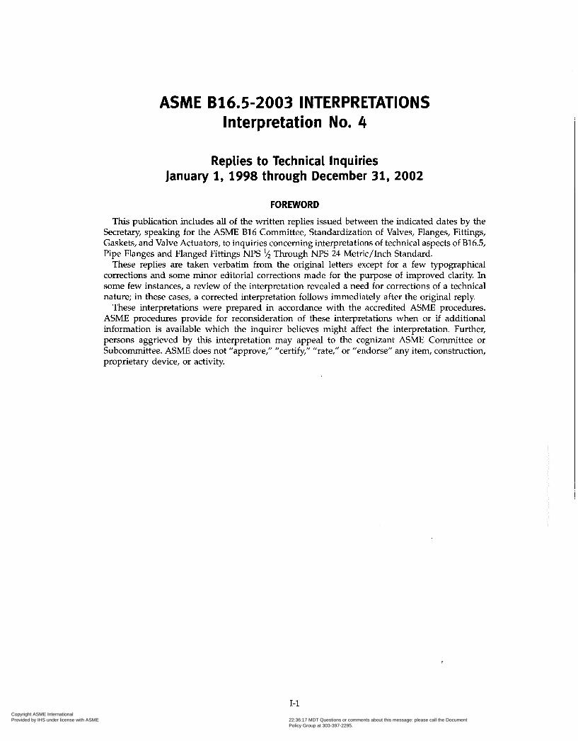
ASM E B 1 6.5 -2 O O 3 I NTE R P R ETATI ON S Interpretation No. 4
Replies to Technical Inquiries January 1, 1998 through December 31, 2002
FOREWORD
This publication includes all of the written replies issued between the indicated dates by the Secretary, speaking for the ACME B16 Committee, Standardization of Valves, Flanges, Fittings, Gaskets, and Valve Actuators, to inquiries concerning interpretations of technical aspects of B16.5, Pipe Flanges and Flanged Fittings NPS i/2 Through NPS 24 Metric/Inch Standard.
These replies are taken verbatim from the original letters except for a few typographical corrections and some minor editorial corrections made for the purpose of improved clarity. In some few instances, a review of the interpretation revealed a need for corrections of a technical nature; in these cases, a corrected interpretation follows immediately after the original reply.
These interpretations were prepared in accordance with the accredited ACME procedures. ACME procedures provide for reconsideration of these interpretations when or if additional information is available which the inquirer believes might affect the interpretation. Further, persons aggrieved by this interpretation may appeal to the cognizant ACME Committee or Subcommittee. ACME does not "approve," "certify," "rate," or "endorse" any item, construction, proprietary device, or activity.
1-1 Copyright ASME International Provided by IHS under license with ASME
Document provided by IHS Licensee=Qatar Petroleum/5943408001, 09/19/200422:36:17 MDT Questions or comments about this message: please call the DocumentPolicy Group at 303-397-2295.
--```,,`,``,,,,`,,``````,,``,`-`-`,,`,,`,`,,`---
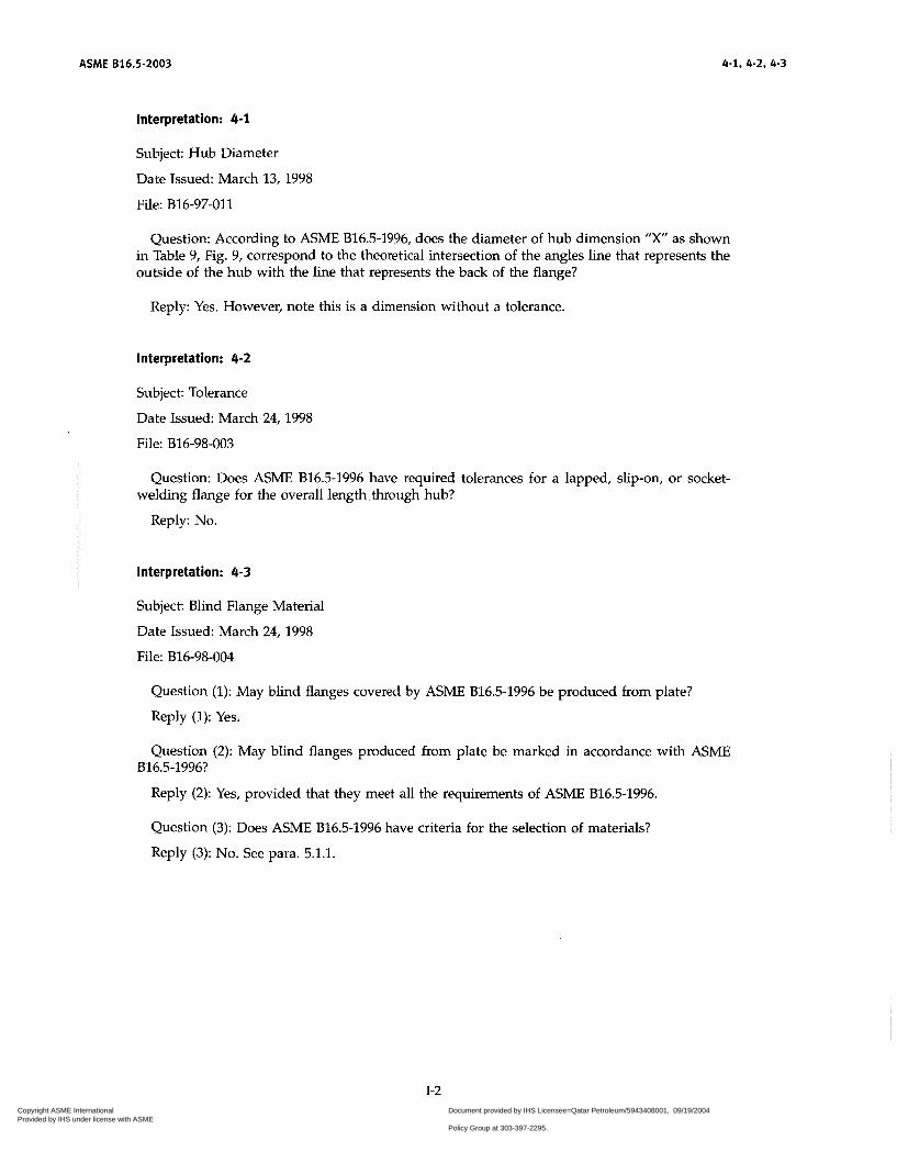
ASME 816.5-2003 4-1, 4-2, 4-3
Interpretation: 4-1
Subject Hub Diameter
Date Issued: March 13, 1998
File: B16-97-011
Question: According to ASME B16.5-1996, does the diameter of hub dimension "X" as shown in Table 9, Fig. 9, correspond to the theoretical intersection of the angles line that represents the outside of the hub with the line that represents the back of the flange?
Reply: Yes. However, note this is a dimension without a tolerance.
Interpretation: 4-2
Subject: Tolerance
Date Issued: March 24, 1998
File: B16-98-003
Question: Does ACME B16.5-1996 have required tolerances for a lapped, slip-on, or socket-
Reply: No.
welding flange for the overall length .through hub?
Interpretation: 4-3
Subject: Blind Flange Material
Date Issued: March 24, 1998
File: B16-98-004
Question (1): May blind flanges covered by ASME B16.5-1996 be produced from plate?
Reply (1): Yes.
Question (2): May blind flanges produced from plate be marked in accordance with ASME
Reply (2): Yes, provided that they meet all the requirements of ASME B16.5-1996.
B16.5-1996?
Question (3): Does ACME B16.5-1996 have criteria for the selection of materials?
Reply (3): No. See para. 5.1.1.
1-2 Copyright ASME International Provided by IHS under license with ASME
Document provided by IHS Licensee=Qatar Petroleum/5943408001, 09/19/200422:36:17 MDT Questions or comments about this message: please call the DocumentPolicy Group at 303-397-2295.
--```,,`,``,,,,`,,``````,,``,`-`-`,,`,,`,`,,`---
4-4, 4-5, 4-6 ASME 816.5-2003
interpretation: 4-4
Subject: Implementation of the Standard, Flange Face Finish
Date Issued: July 21, 1998
File: B16-097-015
Question (1): Is there a mandatory date for the implementation of ASME B16.5-1996?
Reply (1): No. Implementation may be required by reference in a code, specification, sales contract, or public law.
Question (2): May a flange not meeting the flange facing finish requirements of ACME B16.5- 1996 but meeting those of an earlier edition be supplied as being in accordance with the 1996 edition?
Reply (2): Yes, provided that the flange face finish is supplied by arrangement with the purchaser. (See para. 6.4.4.)
Question (3): According to ACME B16.5-1996, para. 6.4.4.3, may a flange with less than 45 grooves per inch or more than 55 grooves per inch meet the flange facing finish requirements as long as the resultant surface finish has a 125 to 250 pin. average roughness?
Reply (3): Yes.
interpretation: 4-5
Subject: Welding Neck Flanges
Date Issued: June 18, 1999
File: B16-99-004
Question (1): Does ACME B16.5-1996 cover welding neck flanges that have the overall length
Reply (1): No.
Question (2): Does para. 6.7.4 of ACME B16.5-1996 allow the conformance designation "B16" to be applied to long weld neck flanges having overall length through hub dimensions greater than specified values?
through hub dimension y greater than the specified values (e.g., long weld neck)?
Reply (2): No. This paragraph applies to only end preparations.
interpretation: 4-6
Subject: Blind Flange Material
Date Issued: October 15, 2001
File: B16-98-013
Question (1): Does ACME B16.5-1996 allow blind flange made from a plate material listed in
Reply (1): No.
Table 1A to be designated as a forging material in Table lA?
Question (2): Does ACME B16.5-1996 permit blind flanges to be of a plate material as listed in Table IA for all pressure classes covered in ASME B16.5-1996 (150, 300,400, 600, 900, 1500, and 2500)?
Reply (2): Yes.
1-3 Copyright ASME International Provided by IHS under license with ASME
Document provided by IHS Licensee=Qatar Petroleum/5943408001, 09/19/200422:36:17 MDT Questions or comments about this message: please call the DocumentPolicy Group at 303-397-2295.
--```,,`,``,,,,`,,``````,,``,`-`-`,,`,,`,`,,`---
ASME 816.5-2003 4-7,4-a, 4-9, 4-10
interpretation: 4-7
Subject: Materials Conformance
Date Issued: January 31, 2001
File: B16-98-017
Question: In accordance with ASME B16.5-1996, may a flange made from a material other than that of a material specification listed in Table 1A be identified as being manufactured in accordance with ACME B16.5?
Reply: No.
interpretation: 4-8
Subject: Material Conformance
Date Issued: January 31, 2001
File: B16-99-03
Question: May a flange meeting all of the relevant dimensional requirements of ASME B16.5- 1996 that is integrally forged or cast to another product be marked as in para. 4.1.1 to indicate conformance to the B16.5 Standard?
Reply: No.
interpretation: 4-9
Subject: Dual Markings
Date Issued: January 31, 2001
File: B16-99-12
Question: In accordance with ACME B16.5-1996, para. 4.14, may flanges NPS ?$ through NPS 3% meeting all of the requirements for Class 600 be marked to show conformance with both Class 400 and Class 600?
Reply: Yes.
Interpretation: 4-10
Subject: Welding End Preparation for Welding Neck Flanges
Date Issued: January 31, 2001
File: B16-99-14
Question: In ASME 816.5-1996, para. 6.7.1, the referenced figures are for attachment of flanges to pipe with wall thickness 0.19 in. and larger. May weld preparations for pipe wall thickness less than 0.19 in. be used in accordance with para. 6.7.4?
Reply: Yes.
1-4 Copyright ASME International Provided by IHS under license with ASME
Document provided by IHS Licensee=Qatar Petroleum/5943408001, 09/19/200422:36:17 MDT Questions or comments about this message: please call the DocumentPolicy Group at 303-397-2295.
--```,,`,``,,,,`,,``````,,``,`-`-`,,`,,`,`,,`---
4-11, 4-12, 4-13, 4-14 ASME 816.5-2003
Interpretation: 4-11
Subject: Socket Weld Flanges
Date Issued: January 31, 2001
File: B16-00-03
Question (1): In ACME B16.5-1996, including 1998 Addenda (a), various tables (for example Table 9) have illustrations that show the location of the applicable tabulated dimensions. For socket welding flanges, these illustrations note a limiting flange size range. Are socket-welding flanges in sizes outside this range, covered by ASME B16.5?
Reply (1): No.
Question (2): May socket welding flanges, in sizes greater than NPS 3 (NPS 2% for class 1500), which conform to the requirements of ACME B16.5-1996, including 1998 Addenda (a), with all dimensions listed in the applicable tables met, be stamped ”B 16” in accordance with para. 4.14?
Reply (2): No. Socket welding flanges in these larger sizes are not included in the requirement of B16.5.
Interpretation: 4-12
Subject: Dimensional Requirements
Date Issued: January 31, 2001
File: B16-00-004
Question: In accordance with ACME B16.5-1996, including 1998 Addenda (a), are there require- ments for the geometry of the shoulder at the circumference defined by diameters designated R in Fig. 7?
Reply: No.
Interpretation: 4-13
Subject: Marking for Welding Neck Flanges
Date Issued: January 31, 2001
File: B16-00-12
Question: Does ASME 816.5-1996 require marking in addition to that described in para. 4 for
Reply: No.
socket welding or welding neck flanges?
Interpretation: 4-14
Subject: Material Conformance
Date Issued: February 1, 2002
File: B16-C-01-01
Question: In accordance with ACME B16.5-1996 Edition, 1998 Addenda (a), may flanges manu- factured of materials other than those listed in Table 1A be marked as being in conformance with ACME B16.5 as required by para. 4.14?
Reply: No. See para. 5.1.
1-5 Copyright ASME International Provided by IHS under license with ASME
Document provided by IHS Licensee=Qatar Petroleum/5943408001, 09/19/200422:36:17 MDT Questions or comments about this message: please call the DocumentPolicy Group at 303-397-2295.
--```,,`,``,,,,`,,``````,,``,`-`-`,,`,,`,`,,`---

ASME 816.5-2003 4-15, 4-16, 4-17
Interpretation: 4-15
Subject: Lapped Joint Flanges Thickness
Date Issued: February 1, 2002
File: B16-C-01-02
Question: What minimum thickness does ACME B16.5-1996, 1998 Addenda (a), require for
Reply: Dimension "C" as shown in Tables 9,12,15,18,21,24, and 27. See para. 7.4 for tolerance.
lapped joint flanges?
Interpretation: 4-16
Subject: Marking Requirements
Date Issued: February 20, 2002
File: B 16-C-01-03
Question (1): According to B16.5-1996, 1998 Addenda (a), is it required that the designation
Reply (1): It is required that "B16" be marked on the flange. See para. 4.1.4.
"B16" or the designation "B16.5" be marked on the flange?
Question (2): Does marking "B16.5" in lieu of "B16", as required, render the flange nonconform-
Reply (2): No.
ing to ACME 816.5-1996, 1998 Addenda (a)?
Interpretation: 4-17
Subject: Flange Thickness
Date Issued: September 2,2002
File: 02-02830
Question: According to ACME B16.5-1996 edition, 1998 Addenda (a), is it acceptable for the flange thickness to taper to the edge and be thinner than the flange thickness "C" dimension listed in the dimensional tables?
Reply: No. See para. 7, Tolerances.
1-6 Copyright ASME International Provided by IHS under license with ASME
Document provided by IHS Licensee=Qatar Petroleum/5943408001, 09/19/200422:36:17 MDT Questions or comments about this message: please call the DocumentPolicy Group at 303-397-2295.
--```,,`,``,,,,`,,``````,,``,`-`-`,,`,,`,`,,`---

Copyright ASME International Provided by IHS under license with ASME
Document provided by IHS Licensee=Qatar Petroleum/5943408001, 09/19/200422:36:17 MDT Questions or comments about this message: please call the DocumentPolicy Group at 303-397-2295.
--```,,`,``,,,,`,,``````,,``,`-`-`,,`,,`,`,,`---

Copyright ASME International Provided by IHS under license with ASME
Document provided by IHS Licensee=Qatar Petroleum/5943408001, 09/19/200422:36:17 MDT Questions or comments about this message: please call the DocumentPolicy Group at 303-397-2295.
--```,,`,``,,,,`,,``````,,``,`-`-`,,`,,`,`,,`---