copyright & disclaimer the barrel and plunger assembly from the blaster and remove the air...
TRANSCRIPT

Copyright & Disclaimer
Copyright Notice:
This e-book is offered for free to the general public. You may distribute it in its original format (PDF), provided that the contents are not changed in any way and you do not claim to be the author. In addition, the information contained in this report may not be used elsewhere without written permission from its authors. Any persons or entities found in violation of infringing the copyright of this report will be prosecuted to the full extent of the law. This e-book is for informational purposes only and its authors do not earn any profit from its distribution. NERF is a registered trademark of Kenner Toys, which is an affiliate of Hasbro, Inc. The authors of this e-book are not affiliated with the aforementioned parties and do not intend to infringe upon any copyright, trademark, or patent.
Disclaimer:
Individual results may vary. Modding blasters is a hobby of ours, and in no way do we claim to be experts on the subject. We’ve written this e-book for other enthusiasts who want to accomplish what we have with our blasters. However, due to legal reasons, we're unable to guarantee any results and the content in this e-book should not be considered professional advice.
The use of this information and recommended products should be based on your own due diligence. You agree not to hold the authors and/or distributors of this e-book liable for any success or failure of your endeavors that are directly or indirectly related to the
purchase and use of our information, recommended products and services.
Table of Contents
Introduction ...........................................................................................................................1
Opening the Blaster .................................................................................................2
Air Restrictor and Dead Space Removal ............................7
Post Removal and Foam Seal Replacement ............ 15
Spring Tensioning and O-ring Seal ......................................... 22
Brass Barrel Mod ..................................................................................................... 28
1 | P a g e
Introduction
What is a Mod?
A modification or “mod” is anything you do to your blaster that changes its looks, form,
or functionality. Doing a custom paint job, adding your own accessories and parts, and
working on the internals to increase power are all considered mods.
Why Mod?
There are a plethora of reasons to mod a blaster:
A modded blaster is a great addition to a costume.
A blaster that you mod becomes your own work of art.
A modded blaster can shoot further and with more intensity compared to FOF
(fresh out of factory) blasters. It can give you the upper hand in your next battle.
Cosmetic modding, when done right, yields stunning results. A humble foam
blaster can become anything from a dystopian “steampunk” gun to a clean cut
weapon right out of science fiction. They can even mimic weapons out of video
games and movies.
Regardless of the reason, modding is an incredibly fun hobby that creates custom
works of art out of average foam blasters.
Dangers of Modding
If performed incorrectly, modifications can reduce performance or render the blaster
inoperable. When performing even basic mods, there is always a risk of losing parts,
cracking plastic, or not being able to re-assemble the blaster. Some of the more
common blasters' internal pictures can be found online, and it is worthwhile to use these
as references.
When performing cosmetic mods, care must be taken in order to not lock up any moving
parts. Without a few layers of a hard clear coat, paint can gum up areas where plastic
slides on plastic. For more complex mods like barrel replacement and fabrication of
sealed breech, you must take into consideration the volume of the plunger tube in
relation to the barrel length, and spring power must also be increased. So make sure
you know what you are getting yourself into before you start a mod.
2 | P a g e
Chapter 1: Opening the Blaster
It is important to be familiar with your blaster’s internal structure in order to carry out any
performance related mods. Be sure to remember what size screws go where and make
sure no small springs shoot out when the blaster is opened. The blaster should be
unloaded with the mainspring relaxed. Try to avoid opening the blaster when it is in the
cocked position.
Supplies Needed:
• Small Phillips Head Screwdriver
• Small Flat Head Screwdriver
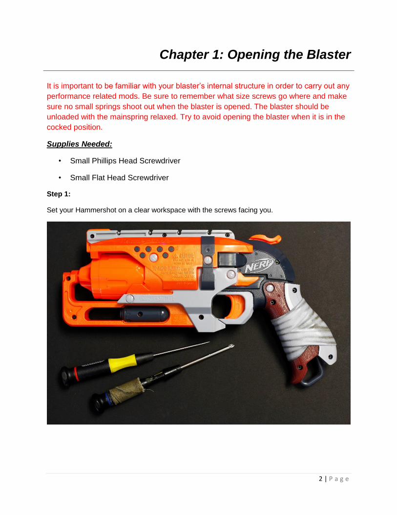
Step 1:
Set your Hammershot on a clear workspace with the screws facing you.

3 | P a g e
Step 2:
Remove all of your screws with the Phillips head screwdriver and set them aside.
Be careful not to lose them!
Step 3:
At this point, the blaster should easily separate into two halves. If the shell resists being split
apart, double check to make sure that all the screws have been removed. If the issue continues,
use a flat head screwdriver and gently pry around the seam until the blaster separates.
Caution: Make sure you do not lose the accessory tooth, which is located on top of the blaster.

4 | P a g e
5 | P a g e
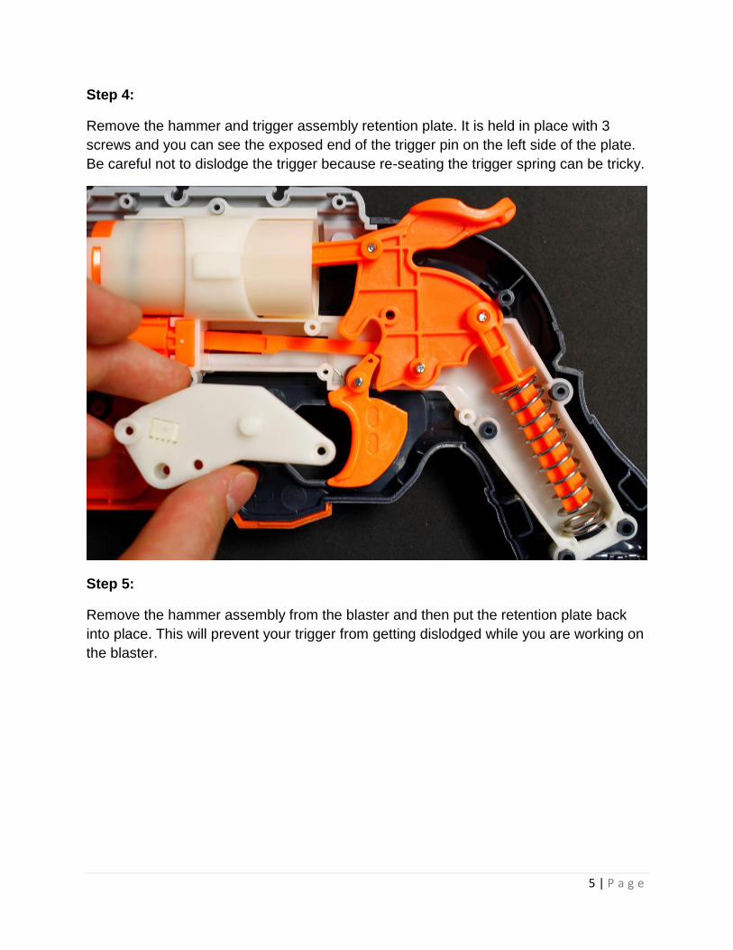
Step 4:
Remove the hammer and trigger assembly retention plate. It is held in place with 3
screws and you can see the exposed end of the trigger pin on the left side of the plate.
Be careful not to dislodge the trigger because re-seating the trigger spring can be tricky.
Step 5:
Remove the hammer assembly from the blaster and then put the retention plate back
into place. This will prevent your trigger from getting dislodged while you are working on
the blaster.

6 | P a g e
You do not need to screw the plate on in order for it to secure the trigger. Just pressing
it back into place should be enough.
7 | P a g e
Chapter 2: Air Restrictor and
Dead Space Removal
The air restrictor (AR) slows down the flow of air from the plunger to the dart. This
device serves to reduce the blaster's power and prevent the plunger from slamming into
the plunger tubing at full speed. This drastically reduces the noise generated during
firing.
The barrel posts prevent you from using shortened or solid darts in your blaster.
Removing them allows you to get creative with your darts. For example, loading two
short darts in each chamber for a mini shotgun effect at close range!
Supplies Needed:
Small flat head screwdriver
Glue (hot glue works best)
Wire cutters, plastic snips, or hobby knife
Something to keep the airway open when you fill the dead space with glue, (large
straw, marker with grease on it, tightly rolled paper with tape, etc.)
Step 1:
Remove the barrel and plunger assembly from the blaster and remove the air restrictor
housing from the plunger tube by carefully prying at the retention tabs with the flat head
screwdriver. The tabs may break but that is ok because we will be gluing the air
restrictor housing back into place.

8 | P a g e

9 | P a g e
Be careful not to lose this spring!

10 | P a g e
Step 2:
Remove the air valve and spring and cut out the small plastic divider. These can be
discarded. At this point it is a good idea to thoroughly clean the inside of the air
restrictor housing to remove any residual grease.

11 | P a g e
Step 3:
Block off the airway with something that is both wide enough to keep it open and will not stick
too badly to your glue of choice. Thick foam can also be used in place of glue. But for this
tutorial, we will be filling the dead space with hot glue.

12 | P a g e
Step 4:
Fill the rest of the orange air restrictor housing with glue or your filler of choice.

13 | P a g e
Step 5:
While the glue is drying, cut away the air restrictor guide posts found inside the plunger body.
14 | P a g e
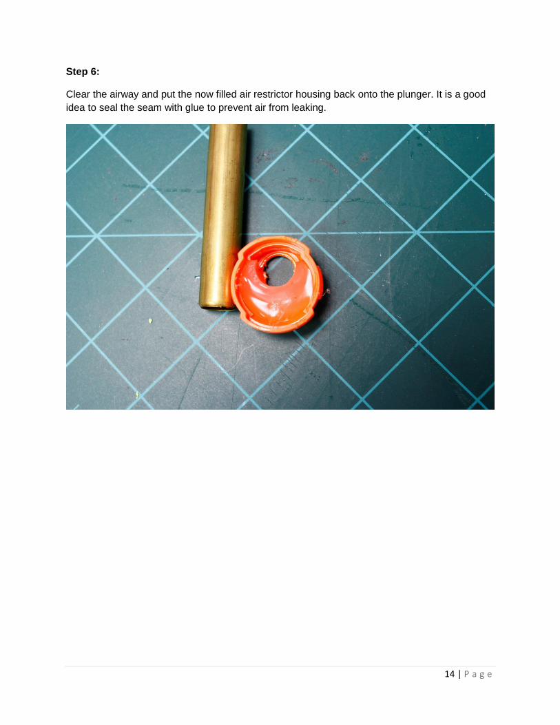
Step 6:
Clear the airway and put the now filled air restrictor housing back onto the plunger. It is a good
idea to seal the seam with glue to prevent air from leaking.
15 | P a g e
Chapter 3: Post Removal and Foam Seal
Replacement
The barrel posts prevent you from using shortened or solid darts in your blaster. Removing them
allows you to get creative with your darts. For example, loading two short darts in each chamber
for a mini shotgun effect at close range!
The foam seal that comes standard on Hammershots is much weaker than the seal found on
the Strongarm, and we have seen many seals come from the factory without even being glued
on all the way. Replacing the seal with craft foam will greatly extend the life of your blaster.
Supplies Needed:
2mm EVA craft foam (if you can find foam with an adhesive back, get it)
Glue (super glue works best if you don’t have adhesive foam)
Small flat head screwdriver or hobby knife for scraping off the old seal
Wire cutters, plastic snips, hobby knife, or dremel
High grit sandpaper
Scissors

16 | P a g e
Step 1:
Remove the cylinder from your blaster and cut the small plastic tabs that hold the barrel posts in
place. Wire cutters or plastic snips work best for this but a knife or dremel can be used.
17 | P a g e
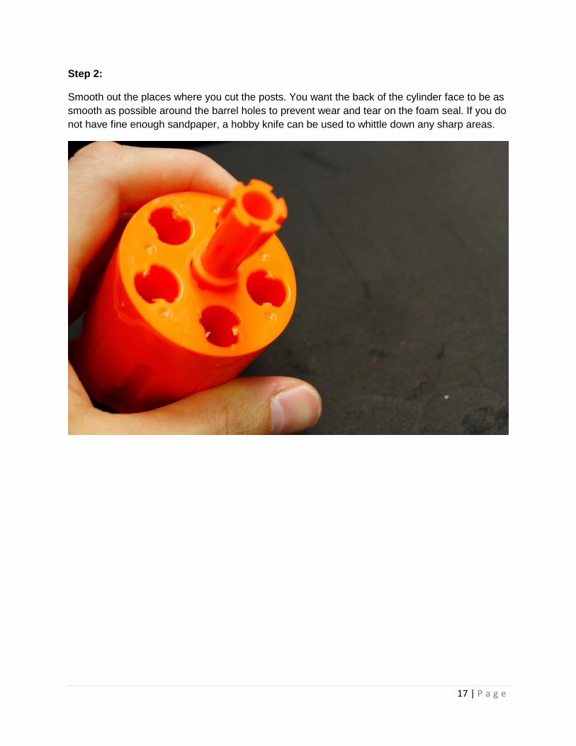
Step 2:
Smooth out the places where you cut the posts. You want the back of the cylinder face to be as
smooth as possible around the barrel holes to prevent wear and tear on the foam seal. If you do
not have fine enough sandpaper, a hobby knife can be used to whittle down any sharp areas.

18 | P a g e
Step 3:
Remove your plunger body assembly from your blaster and use a small flat head screwdriver or
hobby knife to scrape off the old foam seal.
19 | P a g e
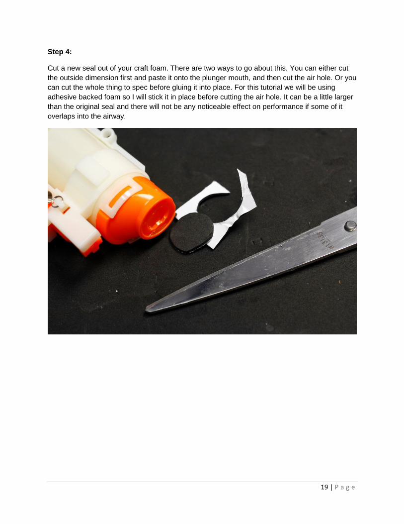
Step 4:
Cut a new seal out of your craft foam. There are two ways to go about this. You can either cut
the outside dimension first and paste it onto the plunger mouth, and then cut the air hole. Or you
can cut the whole thing to spec before gluing it into place. For this tutorial we will be using
adhesive backed foam so I will stick it in place before cutting the air hole. It can be a little larger
than the original seal and there will not be any noticeable effect on performance if some of it
overlaps into the airway.

20 | P a g e
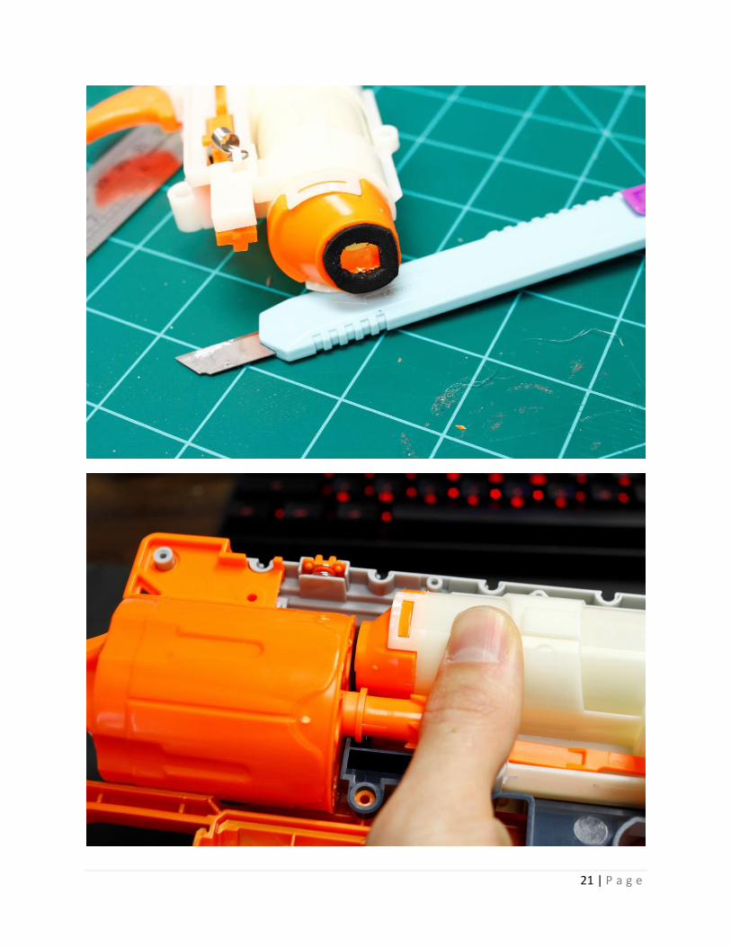
Step 5:
Stick your new seal onto the plunger body and trim any excess foam with a craft knife. If you
want, you can add a thin coat of grease to both the foam seal and the back of the cylinder. But
keep in mind that this may lead to dirt and debris buildup.
21 | P a g e

22 | P a g e
Chapter 4: Spring Tensioning and O-ring Seal
It is possible to get more performance out of your stock spring by adding a spacer that keeps
under tension. These spacers can be made out of any rigid material as long as the spring guide
can pass through it.
Adding Teflon tape to the plunger head increases tension on the o-ring and forces it to form a
better seal with the inside of the plunger body.
Supplies Needed:
A short piece of ½ inch CPVC pipe or other cylindrical material that will fit between the
spring and spring stop
Roll of Teflon tape
Hacksaw or PVC pipe cutter
Small flat head screwdriver
Step 1:
Remove the hammer/plunger assembly from your blaster.
23 | P a g e
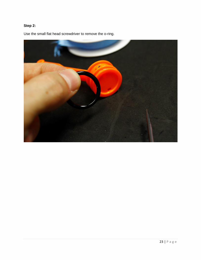
Step 2:
Use the small flat head screwdriver to remove the o-ring.

24 | P a g e
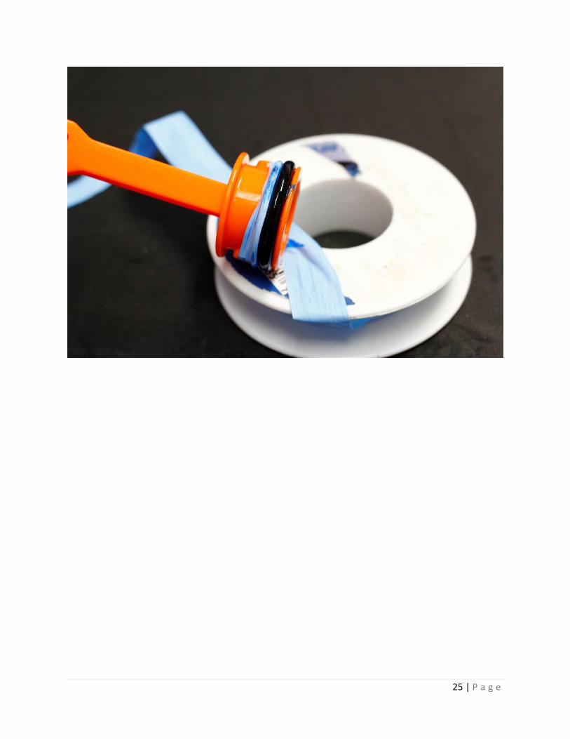
Step 3:
Add 3-5 wraps of Teflon tape inside the o-ring groove of the plunger head, and then test fit the
plunger in the plunger body. If the fit is too tight, remove some of the Teflon tape. You need to
be careful not to use too much tape or there will be too much friction between the o-ring and the
plunger body, and performance will be negatively affected.
Trim any excess Teflon tape from the plunger head and test fit the o-ring. If there is too much
friction between the o-ring and the inside of the plunger body, remove some of the tape.
25 | P a g e

26 | P a g e
Step 4:
Cut a 1/4 inch (more can be used, but make sure it does not interfere with priming) section of
CPVC and slide it over the spring guide post. Then slide your spring onto the post.

27 | P a g e
Step 5:
Reinstall the hammer assembly into the plunger body housing, screw down the retention plate,
and make sure everything moves smoothly.
28 | P a g e
Chapter 5: Brass Barrel Mod
Adding brass barrels to the Hammershot is a fairly advanced mod that requires some
specialized equipment. This mod squeezes the most performance possible out of the
Hammershot platform by making more efficient use of the plunger’s air volume.
Caution: The exposed muzzles of the brass barrels can be sharp!
Supplies Needed:
17/32” brass tubing
Dremel with metal cutting wheel
17/32” drill bit
Drill press and vice (a hand drill can be used, but it is important to make sure you can
drill straight down through the cylinder)
Sandpaper
File
Block of scrap wood
29 | P a g e
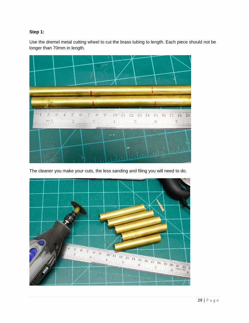
Step 1:
Use the dremel metal cutting wheel to cut the brass tubing to length. Each piece should not be
longer than 70mm in length.
The cleaner you make your cuts, the less sanding and filing you will need to do.
30 | P a g e
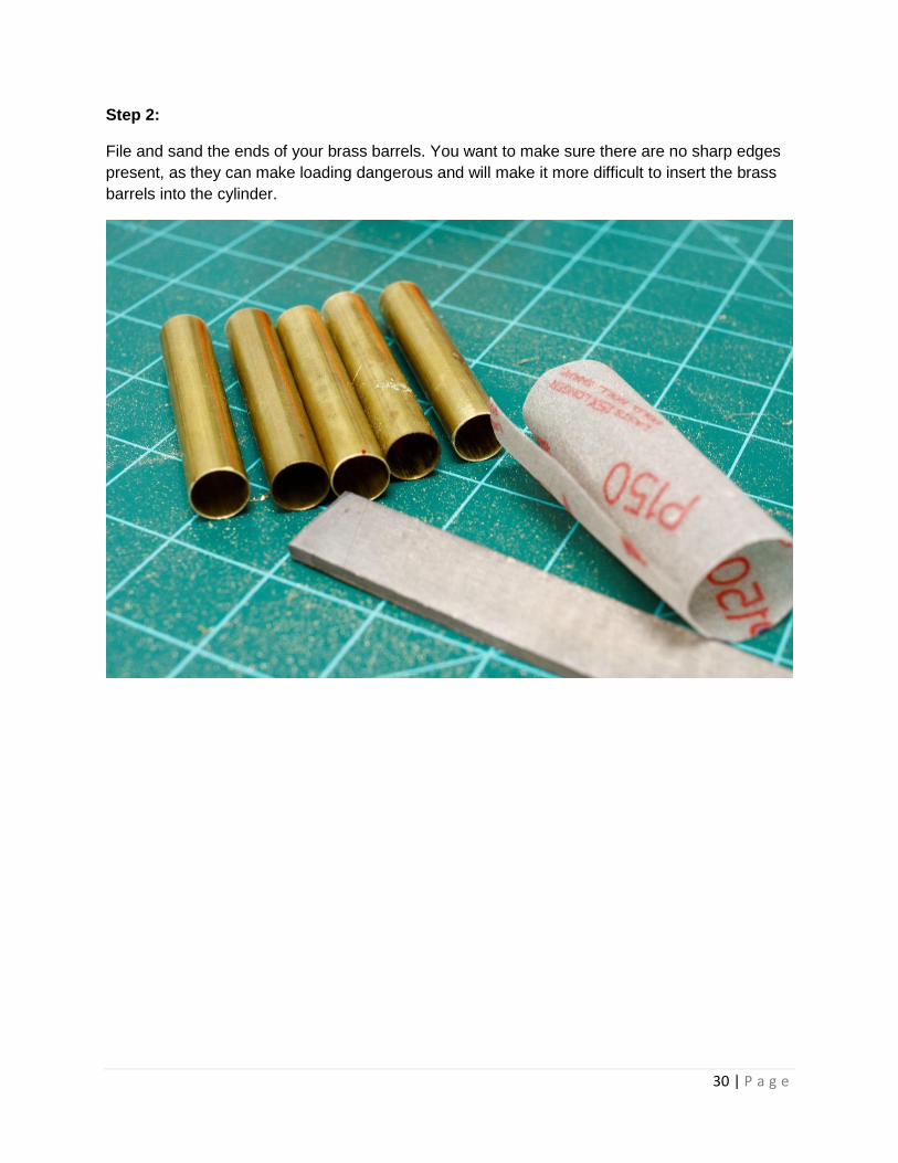
Step 2:
File and sand the ends of your brass barrels. You want to make sure there are no sharp edges
present, as they can make loading dangerous and will make it more difficult to insert the brass
barrels into the cylinder.
31 | P a g e
Step 3:
Secure your cylinder in a vice with the muzzles pointing upward, and position it under your drill
press. Use the 17/32” drill bit to bore out the cylinder’s chambers. Take your time and clear the
holes and drill bit of material often. You need to go slow and back the drill bit out often to avoid
melting the walls of the cylinder. You may need to remove the rotation mechanism from the
back of your cylinder in order to fit it in the vice.

32 | P a g e

33 | P a g e
Step 4:
Press your brass barrels into the cylinder one at a time using the scrap wood block. It is a good
idea to remove the rotating mechanism from the back of the cylinder so you have a nice flat
surface to press against. A rubber mallet can be used to during this process, but care must be
taken not to crack the cylinder.
34 | P a g e
Make sure the barrels are flush or close to flush with the very front of the cylinder, or your
cylinder will not rotate when installed. The barrels pictured below need to be hammered in
further.
35 | P a g e
Step 5:
Reassemble blaster and test fire!
