copyright notice · welcome 1 welcome thank you for purchasing the sabre™ router. the sabre is a...
TRANSCRIPT


Copyright Notice
COPYRIGHT 2003 Gerber Scientific Products, Inc. All Rights Reserved.
This document may not be reproduced by any means, in whole or in part, without written permission ofthe copyright owner.
This document is furnished to support the Sabre Router. In consideration of the furnishing of theinformation contained in this document, the party to whom it is given assumes its custody and controland agrees to the following:
1 The information herein contained is given in confidence, and any part thereof shall not be copied orreproduced without written consent of Gerber Scientific Products, Inc.
2 This document or the contents herein under no circumstances shall be used in the manufacture orreproduction of the article shown and the delivery of this document shall not constitute any right orlicense to do so.
Printed in USA
GSP and GRAPHIX ADVANTAGE are registered trademarks of Gerber Scientific Products, Inc. Sabre, ART Path, T-Vac, OMEGA, Support First, and Gerber Gold are trademarks of Gerber Scientific Products, Inc. 3M is a registeredtrademark of 3M. Adobe Illustrator and Encapsulated PostScript are registered trademarks of Adobe Systems, Inc.CASmate-Pro is a registered trademark of ScanVec, Inc. CorelDRAW is a registered trademark of Corel SystemsCorporation. Gatorfoam is a registered trademark of International Paper. Hewlett-Packard is a registered trademarkand HPGL is a trademark of Hewlett-Packard Company. 3-IN-ONE is a registered trademark of the WD-40Company. Marvel is a trademark of Marvel Oil Company. Microsoft and MS-DOS are registered trademarks ofMicrosoft Corp. Signfoam is a trademark of Sign Arts Products Corporation. Windows is a registered trademark ofMicrosoft in the U.S. and other countries.

FCC Notice
Warning: Changes or modifications to this unit not expressly approved by the party responsible forcompliance could void the user’s authority to operate the equipment.Note: This equipment has been tested and found to comply with the limits for a Class A digital device,pursuant to Part 15 of the FCC rules. These limits are designed to provide reasonable protection againstharmful interference when the equipment is operated in a commercial environment. This equipmentgenerates, uses, and can radiate radio frequency energy and, if not installed and used in accordance withthe instruction manual, may cause harmful interference to radio communications. Operation of thisequipment in a residential area is likely to cause harmful interference in which case the user will berequired to correct the interference at his own expense.
RS-232 shielded cables must be used with this unit to ensure compliance with the Class A FCC limits.
This Class A digital apparatus complies with Canadian ICES-003.Cet appareil numérique de la classe A est conforme à la norme NMB-003 du Canada.
Contents
Welcome ....................................................................................................................................... 1
About this manual................................................................................................................................... 1Conventions ............................................................................................................................................. 2Customer support ................................................................................................................................... 2
Getting to Know the Sabre ....................................................................................................... 4
Standard components ............................................................................................................................. 4Electrical cabinet................................................................................................................................... 6Emergency power shutoff switches................................................................................................... 7Control pad ........................................................................................................................................... 7Chip removal system........................................................................................................................... 8
Operational concepts .............................................................................................................................. 8The role of the design program.......................................................................................................... 8The role of ART Path ........................................................................................................................... 9Axes of movement ............................................................................................................................... 9Machine orientation point................................................................................................................... 9Job home position................................................................................................................................. 9Z axis initialization............................................................................................................................. 10
Getting Started........................................................................................................................... 11
Power up ................................................................................................................................................ 11First time or after loading a firmware revision .............................................................................. 11Normal power-up .............................................................................................................................. 12Power-up tests .................................................................................................................................... 12
Exploring the control pad and message displays ............................................................................. 13Control pad ......................................................................................................................................... 13Message displays................................................................................................................................ 15
System settings ...................................................................................................................................... 16Returning to default configuration settings ................................................................................... 16Choosing the language for message displays ................................................................................ 16Choosing English or metric measurement units............................................................................ 17Setting acceleration ............................................................................................................................ 18Setting positioning rate ..................................................................................................................... 18Using table protection ....................................................................................................................... 19Setting start delay............................................................................................................................... 20Selecting the job data type ................................................................................................................ 20
Cutting tools........................................................................................................................................... 21Collets .................................................................................................................................................. 21Installing a cutting tool...................................................................................................................... 22
Removing a tool..................................................................................................................................... 23Installing and replacing a pen tool ..................................................................................................... 24

Using the chip removal system ........................................................................................................... 25Removing the pressure foot assembly................................................................................................ 26
Changing the pressure foot pad....................................................................................................... 27Understanding Surface Reference....................................................................................................... 27
Setting the surface reference............................................................................................................. 28Verifying surface reference at the Sabre ......................................................................................... 29
Z axis initialization................................................................................................................................ 30Establishing a table surface reference.............................................................................................. 30Establishing material surface reference........................................................................................... 31
Adjusting the depth .............................................................................................................................. 32Adjusting a tool's initialization depth ............................................................................................. 32Temporarily adjusting the initialization depth of a tool............................................................... 33
Mat milling............................................................................................................................................. 33Safety guidelines ................................................................................................................................ 33Milling the mat ................................................................................................................................... 34
Routing ........................................................................................................................................ 37
Safety guidelines ................................................................................................................................... 37Pre-job checklist..................................................................................................................................... 38Warming up the spindle....................................................................................................................... 39Holding down material ........................................................................................................................ 39
Using clamps....................................................................................................................................... 40Using the T-Vac .................................................................................................................................. 41Using sacrificial material................................................................................................................... 41Material hold down guidelines ........................................................................................................ 42
Setting speed and feeds ........................................................................................................................ 44Changing spindle speed.................................................................................................................... 44Overriding the X,Y feed rate............................................................................................................. 45
Position control...................................................................................................................................... 46Returning to table 0,0 (orientation point) ....................................................................................... 47
Routing the job....................................................................................................................................... 47Emergency stopping .......................................................................................................................... 49Pausing and restarting routing......................................................................................................... 49Verifying job size and boundaries ................................................................................................... 50Setting and changing job home position......................................................................................... 50Displaying elapsed job time.............................................................................................................. 51
Manual routing...................................................................................................................................... 51Controlling the spindle air on ATC equipped machines................................................................. 52Changing motors................................................................................................................................... 53
Maintenance .............................................................................................................................. 54
Daily inspection..................................................................................................................................... 54Daily cleaning ........................................................................................................................................ 54
Recommended cleaning supplies .................................................................................................... 54Table surface cleaning ....................................................................................................................... 55X way cleaning.................................................................................................................................... 55Y way cleaning.................................................................................................................................... 55Lead screw cleaning........................................................................................................................... 55Electrical cabinet air filter cleaning.................................................................................................. 56
Weekly maintenance............................................................................................................................. 56Z axis lubrication................................................................................................................................ 56
Troubleshooting ........................................................................................................................ 57

Error Messages .......................................................................................................................... 64
Options ........................................................................................................................................ 68
High Frequency Spindle Option ...................................................................................................... 68Mist Coolant Option .......................................................................................................................... 68T-Vac Option....................................................................................................................................... 69Engraver and Engraver Vacuum Options ...................................................................................... 69Automatic Tool Changer Option ..................................................................................................... 69
Specifications............................................................................................................................. 70
Index ............................................................................................................................................ 71


Welcome 1
Welcome
Thank you for purchasing the Sabre™ Router. The Sabre is a router/engraver for use indimensional sign making, woodworking, and parts fabrication. It offers high-speed routing oflettering and graphic designs, dependability, and ease of use, minimal maintenancerequirements, and configuration flexibility. The Sabre can cut designs from a variety ofmaterials − foams, plastic, wood, composites, and non-ferrous metals − as well as draw all typesof text and graphics.
The Sabre is available in two table sizes: 4 foot x 4 foot (122 cm x 122 cm) and 4 foot x 8 foot (122cm x 244 cm). A variety of options enhance operation. The standard 3¼ hp router motor may bereplaced with the High Frequency Spindle Option for quiet, variable speed operation up to24,000 rpm. (The Engraver Option provides the accuracy of an engraver with the cuttingcapabilities of a router in a single system.) The T-Vac Vacuum Table Option provides superiorholddown for a wide variety of material size and types.
The Sabre can rout designs created by using many standard design programs — Composer inGerber OMEGA™ or GRAPHIX ADVANTAGE®, CorelDRAW®, and CASmate®. Regardless ofthe program used to create the design to be routed, the Gerber ART Path™ software preparesthe design for routing by the Sabre. ART Path allows you to generate tool paths of varyingdepths, then output the job to the Sabre. When used with design programs other than Gerberprograms, the open architecture ART Path Software Option enables you to import standard fileformats into ART Path for tool path generation.
WARNING: The Sabre is a computer-controlled machine tool and should be usedonly by trained operators. The safety guidelines in this manual must be followed atall times to avoid risk of injury.
About this manualThis manual covers the basic information needed for using the Sabre. The manual is arranged asfollows:
♦ Getting to Know the Sabre describes the items that make up the Sabre system andintroduces concepts that will help you operate the Sabre safely and efficiently.
♦ Getting Started guides you through the process of setting up the Sabre, power up,Sabre system settings to meet your needs, installing and removing tools, and more.
♦ Routing provides detailed instructions for routing.
♦ Maintenance outlines the procedures you should perform to keep the Sabre in goodrunning order.

2 Sabre Owner’s Guide
♦ Troubleshooting suggests ways to analyze and respond to problems.
♦ Error Messages lists messages that you may see on your Sabre screen, the possiblecauses and suggested remedies.
♦ Options provides an overview of options which may be purchased with the Sabre.
♦ Specifications outlines size and performance specifications.
For detailed information regarding ART Path, OMEGA, or GRAPHIX ADVANTAGE, refer toyour ART Path, OMEGA, or GRAPHIX ADVANTAGE User's Guides or on-line Help.
ConventionsSpecial information in this manual is presented in notes, cautions, and warnings as follows:
Note: A note contains important information that could affect successful completion of a task.
CAUTION: A caution statement contains information which, if not observed, couldresult in damage to the equipment.
WARNING: A warning statement contains information which, if not observed,could result in personal injury.
This type style is used to represent what is displayed on the Sabre’s LCD display screen.
Customer support If you have questions regarding using, maintaining, or troubleshooting the Sabre or the ATC,please contact your Gerber distributor or the Gerber Router Support Group at:
phone: 860-528-1028fax: 860-290-5568
e-mail: [email protected]
www.gspinc.com
If you are a Support First™ member, use your toll-free assistance number (for more informationon Support First, call 860-528-1028).
For field service telephones, the number is 800-828-5406 (US and Canada). Internationalcustomers call 860-643-1515.
Gerber FastFacts™ (answers to technical and service questions) telephone number is 800-222-7446. FastFacts are also available on the Gerber web site.
Please use a phone that is close to your system and have the following information availablewhen you call:

Welcome 3
♦ Microsoft Windows version number
♦ GSP system ID number (System Identification String in Gerber System Tray or in GSPSetup of GRAPHIX ADVANTAGE)
♦ System serial number (on security block)
♦ Sabre serial numbers (on back of beam and electrical cabinet)
If you have OMEGA or GRAPHIX ADVANTAGE, please have the following information ready:
♦ OMEGA or GRAPHIX ADVANTAGE program disks
♦ Windows hardware utilities disks
♦ OMEGA or GRAPHIX ADVANTAGE, and Windows user manuals

4 Sabre Owner’s Guide
Getting to Know the Sabre
This section describes the components that accompany the standard Sabre router so that youwill be able to identify them and understand their function in the routing operation. Thestandard components include:
♦ Tool kit
♦ Electrical cabinet
♦ Control pad
♦ Chip removal system
The Sabre follows a set of operational concepts that are fundamental to successful routing. Theyinclude:
♦ Axes of movement
♦ Table orientation point
♦ Job home position
♦ Z axis initialization
Understanding these concepts will make using the Sabre easier and more reliable. Pleasebecome familiar with these concepts before using the Sabre.
The following options may be purchased to accompany the Sabre:
♦ Mist Coolant Option
♦ High Frequency Spindle Option
♦ T-Vac Option
♦ Engraving Option
♦ Engraver Vacuum Option
♦ Automatic Tool Changer (ATC) Option
Please see “Options” section for descriptions of these options. Use of the T-Vac Option isdescribed in this section of this manual. Each option comes with its own user guide.
Standard componentsThe Sabre is shipped assembled and is installed by an Gerber-authorized installer.

Getting to Know the Sabre 5
Tool kit contents1 tool wrench set3 .250" or 6 mm Gerber Gold™ tools3 .125" or 3 mm Gerber Gold tools1 mat milling tool1 pen tool1 .250" or 6 mm collet1 .125" or 3 mm sleeve1 initialization gage1 pressure foot pad (small)4 spare fuses, various sizes6 clamp assemblies

6 Sabre Owner’s Guide
Electrical cabinet
WARNING: Do not open the electrical cabinet. Dangerous voltages exist in theinterior.
The electrical cabinet distributes power to the Sabre and some of its related devices. It isdesigned to stand on the floor behind or to the right of the router. This location helps protect thecabinet from coolant and debris.
The main ON/OFF power switch is located on the side of the cabinet.
The electrical cabinet also has a switched outlet (115 VAC, 15 amp for domestic units, and 220VAC, 20 amp for export units) to supply power to the chip removal system vacuum.
The front of the electrical cabinet contains a window for viewing eight LED status indicators.You may use these indicators to assist in troubleshooting under the direction of a Gerber servicerepresentative.
Power cordElectrical cabinet

Getting to Know the Sabre 7
Emergency power shutoff switchesThe Sabre is equipped with three emergency power shutoff switches, located as shown below.When you press one of these switches, you trip the main power breaker, removing all power tothe system. These switches should be used only in an emergency when it is necessary to stopsystem operation immediately, not to pause a job.
Control padThe control pad lets you operate the Sabre by making menu selections to:
♦ set up a job
♦ manually move the tool to a desired location
♦ start, stop, or pause a job
♦ change the speed or feed rate
The control pad rests on a bracket convenient to the work surface, but may also be hand held. Itprovides a message display, menu selection keys to make menu selections, move (arrow) keysto move the router motor, and several control keys. The message display shows menus andmessages.

8 Sabre Owner’s Guide
Chip removal systemThe chip removal system helps keep the work area clean during routing by vacuuming chipsinto a customer-supplied vacuum. It is equipped with a pressure foot that rests on theworkpiece and slides easily over the workpiece surface during routing. The pressure footapplies downward force on the material to keep it from lifting during routing.
The chip removal system comes fully installed but requires a customer-supplied 3 hp(minimum), 16 gallon vacuum with a 2.5" (64 mm) diameter hose opening. A hose suppliedwith the Sabre connects to the vacuum hose. The Sabre hose contains a ground strap cable,which protects the Sabre from static discharges that can interrupt operation.
CAUTION: The ground strap cable must be properly installed in order to dischargebuilt-up static electricity which could affect the operation of the system.
Operational conceptsThe Sabre is one part of a complete design and production system. Routing a job on the Sabre isactually the culmination of a design and output process that involves a design program, theGerber ART Path software, and the Sabre controls.
The role of the design programYou will use a design program such as the Gerber OMEGA or GRAPHIX ADVANTAGE tocreate the sign or image you want to rout. The Sabre can also rout designs created by a widevariety of other design programs. If you do not use OMEGA or GRAPHIX ADVANTAGE, thedesign program you use must be able to produce one of the following formats:
♦ AI (Adobe Illustrator® format version 1.1 only)
♦ EPS (Encapsulated PostScript®, Adobe Illustrator format)
♦ DXF (Drawing Interchange File Format)
♦ PRN (Hewlett-Packard Graphics Language, or HPGL™)
♦ G Codes, which are interpreted by the G Code feature (Requires the use ofHyperterminal and the assistance of a Gerber technician.)

Getting to Know the Sabre 9
The role of ART PathThe image created by the design program is essentially two-dimensional. It may be displayedon a screen, cut from vinyl, or printed on a vinyl or paper printer. Routing is three-dimensional,involving not just the outline of the design, but the depth of cut, the tool radius and geometry,and material thickness and surface characteristics. ART Path generates tool paths from designelements. The ART Path user enters depth, speed, and tool information that ART Path uses togenerate the tool path. ART Path then controls output of the file to the Plot Spooler or GQManager queue, which communicates with the Sabre firmware to control routing the design.
This guide does not describe use of ART Path. Please refer to the ART Path and Auto-carve User'sGuide for further information.
Axes of movementThe Sabre has three axes of movement:
♦ The X-axis is from left to right.
♦ The Y-axis is from front to back.
♦ The Z (depth) axis is up and down.
Machine orientation pointThe machine orientation point locates the X-axis at 0,0, the Y-axis at 0,0 and raises the tool to theZ axis position of 0,0. When you turn the power on, the Sabre prompts you to orient the system.The Sabre locates the machine orientation point at the 0,0 position (the front, left corner of theSabre table) as well as the highest elevation of the tool above the table. The Sabre calculates allfuture moves on the table relative to this point.
Job home positionThe job home position is the point on the router table where you want the job to start. Itcorresponds to the start position in the job data. Job home position may be set in the followingways:
♦ Allow the tool position when you press Start to be the job home position.
♦ Set a pre-position (move) from the ART Path output dialog box. The tool position afterthe move is the job home position.

10 Sabre Owner’s Guide
♦ Press the control pad move keys to move the tool to the desired position and press theHome function key.
Note: Use the Home key only if you have already pressed Start and wish to establish a differentjob home position.
The job home position must allow sufficient room for the job to fit within the active cutting area.If job home position causes the job to extend beyond the routing area, the Sabre displays anerror message indicating that the job exceeds table boundaries. To continue, you will have tochange the job home position, ART Path offset, or number of repeats so that it fits within tableboundaries.
Z axis initializationZ-axis movement is the up and down movement of the tool. Z-axis initialization establishes thelocation of the cutting tool relative to the router table (or sacrificial material) surface and theworkpiece material surface. All subsequent up and down moves are made relative to the Zinitialization position. If the Z-axis is not properly initialized, the tool will cut at the wrongdepth and could cut into the table.
The Z-axis may be initialized for two types of routing: through-cutting and non-throughcutting. When initialized for through-cutting, the Z-axis is initialized to the table (or sacrificialmaterial) surface and the Sabre tool cuts entirely through the workpiece during cutting. Wheninitialized for non-through cutting, the Z-axis is initialized to the material surface and the Sabretool plunges into the material to the depth specified in ART Path relative to the surface of thematerial. Refer to the section “Z axis initialization” for detailed instructions.

Getting Started 11
Getting Started
Before using the Sabre to cut a job, perform these preliminary steps:
♦ Connect the chip removal system ground strap.
♦ Make sure all ground straps are securely connected to the ground stud on the rear ofthe electrical cabinet.
♦ Verify that the table mats have been milled to create a perfectly flat surface.
♦ Power up.
♦ Explore the control pad. Refer to the Sabre Router Menu Structure card in the back ofthis manual for details about the menus.
♦ Select the display language.
♦ Select English or metric measurement units.
Power upThere are two power-up sequences:
♦ the first time the Sabre is turned on or after loading a new firmware revision
♦ normal power-up
Since the Sabre is turned on and tested at the factory before shipment, you normally will neversee the “first-time” power-up sequence when you start your router for the first time at yourfacility. However, you will see this sequence after loading a new firmware revision.
First time or after loading a firmware revisionAfter loading a new firmware revision, you must specify the router type (Sabre 404 or 408), thecutting motor type (router motor, high frequency spindle, or ATC spindle), and set theorientation. The sequence and displays are as follows:
To start up the first time or after a firmware revision
1 After the firmware is loaded, the display shows:SELECT MACHINESabre 404A: Change

12 Sabre Owner’s Guide
2 Press A to toggle between Sabre 404 and Sabre 408. Press ENTER when it displaysyour router type. The display shows:
Spindle/RouterRouterA: Change
3 Press A to toggle between Router, Spindle, and ATC Spindle. Press ENTER when thedisplay shows the motor type installed on your router. The display shows:
ORIENTATIONA: Orient System
WARNING: The Sabre will move quickly. Stand away from the table.
CAUTION: If you move the carriage into the front left corner so that it stops againstthe corner, an error will occur. Turn power off and on at the electrical cabinet, sothat the Sabre repeats orientation.
4 Press A. The Sabre moves the tool to the machine orientation position and raises thetool. The display shows:
STATUSSABRE: IdleJOB: Not Ready
When this STATUS message appears, the Sabre is ready for use.
Normal power-up1 Turn on the main power switch on the electrical cabinet. The switch should be
pointing up.
2 The display shows:ORIENTATIONA: Orient System
WARNING: The Sabre will move quickly. Stand away from the table.
CAUTION: If you move the carriage into the front left corner so that it stops againstthe corner, an error will occur. Turn power off and on at the electrical cabinet, sothat the Sabre repeats orientation.
3 Press A. The Sabre moves the tool to the machine orientation position and raises thetool. The display shows:
STATUSSABRE: IdleJOB: Not Ready
4 Whenever this STATUS message is displayed, the Sabre is ready for use.
Power-up testsWhen you turn power on, the Sabre performs diagnostic self-tests. If an error occurs during self-tests, the system emits a continuous beep or a series of beeps. Press RESET on the control pad torepeat the self-test. When the self-tests are complete, the STATUS message shown aboveappears.

Getting Started 13
Exploring the control pad and message displaysThe control pad contains a message display to tell you what the router is doing and to promptyou for information with menus. The control pad keys are used to make menu selections andcontrol the router.
Control padThe control pad consists of:
♦ 4-line message display
♦ 3 job control keys (START, PAUSE, RESET)
♦ 3 menu selection keys (A, B, C)
♦ 4 menu control keys
♦ 12 function keys
♦ 3 Z axis move keys (up and down) with a central speed control key
♦ 5 X,Y axis move keys (right/left, forward/backward) with a central speed control key
Use the control pad keys as follows:
♦ press the arrow keys to toggle between multiple screens of the same menu (MAINMENU 1 and 2, for example)
♦ press the menu selection letter keys (A, B, or C) to make a selection within a menu
♦ press the short cut function keys to go directly to that menu item
♦ press ENTER after pressing the letter key to confirm and record the selection
♦ press EXIT to return to the previous menu without recording changes to the currentmenu
START
PAUSE
RESET
A
B
C
STATUSSABRE: IdleJOB: Not Ready
Message display
Menu control keys
Z axis move keys
X,Y axis move keys
FAST SLOW
EXIT ENTER
TBLZ INIT
Z UP
RPM
SHIFT
MATLZ INIT
ADJDEPTH
FEEDRATE
HOMERET0,0
Function keys
Menu selection keys
Job control keys
ATC DFLT

14 Sabre Owner’s Guide
Some menus have only one letter to make a selection. For example, you can select English ormetric measurements in the Units menu:
UNITSENGLISHA: CHANGE
Repeatedly pressing the A key toggles the choice between English and metric. When the displayshows what you want, press ENTER to confirm the choice. Press EXIT to go to the previousmenu. Continue to press EXIT until the Main Menu appears. Toggle between MAIN MENU 1and MAIN MENU 2 by repeatedly pressing one of the arrow keys.
The following table provides specific information about the control pad.
Job control keys
START Starts or resumes a routing job.
PAUSE Temporarily stops router actions; the stopped job may be restarted.Pause may not take effect immediately.
RESET Stops the job immediately if the router is running, and terminates thejob.
Menu selection keys
A Selects menu choice A.
B Selects menu choice B.
C Selects menu choice C.
Menu control keys
EXIT Returns to the previous menu without recording changes to thecurrent menu.
PAGE UP Displays the previous menu.
PAGE DOWN Displays the next menu.
ENTER Records the menu selection made.
Function keys
TBL Z INT (table init) Allows you to initialize from the table surface for through cutting.
MATL Z INT (materialinit)
Allows you to initialize from the material surface for non-throughcutting.
ADJ DEPTH Temporarily adjust the initialization depth of the current tool.
Z UP Raises the tool to its maximum height. (0,0)
RPM Sets spindle speed (High Frequency Spindle Option only).
FEED (feed rate) Overrides the X,Y feed rate set in ART Path.
HOME Returns to or changes the job home position.
RET 0,0 Moves the tool to the table orientation point (lower left).
ATC Opens the Automatic Tool Changer menu.
DFLT (defaultconfiguration)
Returns to the factory default settings.
SHIFT Press SHIFT and EXIT during manual routing to turn off the motorand raise the tool.

Getting Started 15
Z axis move keys
UP ARROW Raises the tool.
DOWN ARROW Lowers the tool.
FAST Press and hold while pressing the UP or DOWN keys to increase thespeed at which the tool moves.
X,Y axis move keys
UP ARROW Moves the tool toward the back of the table.
DOWN ARROW Moves the tool toward the front of the table.
LEFT ARROW Moves the tool to the left.
RIGHT ARROW Moves the tool to the right.
SLOW Press and release to slow X,Y axis movement. Press and release againto return to normal speed.
Message displaysThe 4-line message display shows menus, instructions, system and job status, and errormessages. Each menu has a title (for example, MAIN MENU 1) followed by information andchoices.
An upper case letter precedes a menu choice that can be modified. If the menu choice can not bemodified, a lower case letter precedes it. For example, if you select Router as the Cutting MotorType in the SETUP menu, you cannot change the spindle speed in the SPEED/FEEDS menu.Spindle speed is not available as indicated by a lower case a in the example on the left. If thefeature is available, an uppercase letter as shown in the example on the right precedes the menuchoice.
SPEED/FEEDS SPEED/FEEDS
a: Spindle speed A: Spindle speed
B: X,Y feed rate B: X,Y feed rate
C: Z feed rate C: Z feed rate
Note that in both examples, X, Y, and Z feed rates (menu choices B and C) are available.
In some cases, pressing a function key displays a menu to let you know if a feature is availableor unavailable. For example, if you press the RPM function key and you have a spindle selectedas the Cutting Motor Type, the SPINDLE SPEED menu automatically opens so that you canchange the speed as shown in the example on the left. If you selected Router as the CuttingMotor Type, you cannot change the spindle speed. In this case, the SPEED/FEEDS menuappears with the Spindle speed choice preceded by a lower case a to show you that this featureis unavailable as shown in the example on the right.
SPINDLE SPEED SPEED/FEEDS06000 RPM a: Spindle speedA: Increase by 100 B: X,Y feed rateB: Decrease by 100 C: Z feed rate
For a complete list of all menus and the menu structure, refer to the Sabre Router MenuStructure card in the back of this manual.

16 Sabre Owner’s Guide
System settingsNote: Gerber recommends that you leave the system settings set to the factory defaults untilyou have more experience in using the Sabre.
You can customize your Sabre operation. The following settings can be altered in theCONFIGURATION and SETUP menus.
♦ Language – Select the language used for the menus. (Only available with the multiplelanguage version of Sabre firmware.)
♦ Units – Select inches or millimeter measurement units.
♦ Acceleration – Set the rate at which the Sabre accelerates so you can achieve thehighest cutting precision or the greatest throughput.
♦ Positioning Rate – Set the speed at which the Sabre moves between shapes.
♦ Table Protection – Provide protection from accidentally cutting into the table surface.
♦ Start Delay – Control how quickly cutting begins after you press START.
Returning to default configuration settingsA function key has been added to the Sabre control pad that automatically returns the Sabre tothe default factory settings. Press the DFLT (default configuration) key to apply the followingsettings to the Sabre.
Feature Setting
Spindle Speed 20000 RPM
X,Y Feed Rate Override 100%
Z Plunge Rate Override 100%
Table Protection OFF
Acceleration Normal
Surface Reference Table
Choosing the language for message displaysThe multiple language version of Sabre firmware can display messages in the followinglanguages: English, Italian, Francais, Deutsche, Espagnol, Portugues, and Nederlands. If youhave a single language version of Sabre firmware this option is not available.
To select a language
1 Press the down arrow key until you see:MAIN MENU 2A: Position controlB: Manual feedC: Configuration

Getting Started 17
2 Press C to select the Configuration menu. Press down until you see:CONFIGURATION 2A: TestingB: SetupC: ATC Menus
3 Press B to select the Setup menu. Press down until you see:SETUP MENU 2A: Select languageB: UnitsC: Positioning rate
4 Press A to select the Select language menu shown below.SELECT LANGUAGEEnglishA: Change
5 Press A to toggle among the languages until you see the correct language.
6 Press ENTER to choose the language. Press EXIT repeatedly until the STATUSmessage appears.
Choosing English or metric measurement unitsThe Sabre can display dimensions in either inches or millimeters.
To select units
1 Press the down arrow key until you see:MAIN MENU 2A: Position controlB: Manual feedC: Configuration
2 Press C to select the Configuration menu. Press down until you see:CONFIGURATION 2A: TestingB: SetupC: ATC Menus
3 Press B to select the Setup menu. Press down until you see:SETUP MENU 2A: Select languageB: UnitsC: Positioning rate
4 Press B to select the Units menu shown below.UNITSEnglishA: Change
5 Press A to toggle between English or metric until you see the correct unitsmeasurement.
6 Press ENTER to choose the units. Press EXIT repeatedly until the STATUS messageappears.

18 Sabre Owner’s Guide
Setting accelerationAcceleration is the rate at which the Sabre gains speed from stop to the full speed set for the jobin ART Path. By default, acceleration is set to Normal. You can also lower the acceleration toincrease precision for very detailed work (Low), or allow the Sabre to automatically adjustacceleration to the geometry of the design (Auto).
Note: When using RT Path 32, the acceleration settings sent from the software override theacceleration settings chosen at the Sabre.
To set acceleration
1 Press the down arrow key until you see:MAIN MENU 2A: Position controlB: Manual feedC: Configuration
2 Press C to select the Configuration menu. Press down until you see:CONFIGURATION 1A: Table protectionB: Acceleration
C: Revision level
3 Press B to select Acceleration. The display reads:ACCELERATIONNormalA: Change
4 Press A to toggle among Normal, Low, and Auto. Press ENTER to record the selection.Press EXIT repeatedly until the STATUS message appears.
Setting positioning rateThe positioning rate is the speed at which the Sabre carriage moves between shapes when thetool is up, when returning to the job home position, and when returning to the table 0,0position. The maximum speed for the Sabre 404 is 1414 inches per minute (ipm) (598.59 mm persecond (mmps)) at the nominal voltage. The maximum for the Sabre 408 is 1300 ipm (550.33mmps) at the nominal voltage. The default for both is 850 ipm (359.83 mmps). To achieve themaximum positioning rate, the nominal input voltage must be at least 220 V AC.
WARNING: For safety reasons, use a positioning rate of 850 ipm until you becomefamiliar with Sabre operation and speed.
To change the positioning rate
1 Press the down arrow key until you see:MAIN MENU 2A: Position controlB: Manual feedC: Configuration

Getting Started 19
2 Press C to select the Configuration menu. Press down until you see:CONFIGURATION 2A: TestingB: SetupC: ATC Menus
3 Press B to select the Setup menu. Press down until you see:SETUP MENU 2A: Select languageB: UnitsC: Positioning rate
4 Press C to select the Positioning rate menu shown below.POSITIONING RATE0850 ipmA: IncreaseB: Decrease
5 Press A or B to change the rate, then press ENTER to choose the rate. Press EXITrepeatedly until the STATUS message appears.
Using table protectionThe Table Protection feature helps prevent accidentally cutting into the table surface when thedepth of cut is greater than the workpiece thickness. When the feature is active, you will beasked to initialize from the table surface even when you are not cutting through the material.The additional initialization enables the Sabre to detect a table-cutting condition. An errormessage displays before cutting when a table-cutting condition exists.
CAUTION: It is possible to cut into the table surface even with the table protectionfeature on if the router has not been initialized properly or if other tool pathparameters have been set incorrectly in ART Path.
To turn the table protection feature on or off
1 Press the down arrow key until you see:MAIN MENU 2A: Position controlB: Manual feedC: Configuration
2 Press C to select the Configuration menu. Press down until you see:CONFIGURATION 1A: Table protectionB: AccelerationC: Revision level
3 Press A to select the Table protection menu shown below.TABLE PROTECTION
OnA: Change
4 Press A to toggle between On and Off, then press ENTER to choose the tableprotection setting. Press EXIT repeatedly until the STATUS message appears.

20 Sabre Owner’s Guide
Setting start delayThe start delay is the time the Sabre waits to begin cutting after the router motor is turned on.This delay allows the motor to achieve the desired speed before cutting. The default is fourseconds.
To set the start delay
1 Press the down arrow key until you see:MAIN MENU 2A: Position controlB: Manual feedC: Configuration
2 Press C to select the Configuration menu. Press down until you see:CONFIGURATION 2A: TestingB: SetupC: ATC Menus
3 Press B to select the Setup menu. Press down until you see:SETUP MENU 1A: Select machineB: Spindle/RouterC: Start delay
4 Press C to select Start delay menu shown below.START DELAY04 secondsA: IncreaseB: Decrease
5 Press A or B to change the rate, then press ENTER to choose the rate. Press EXITrepeatedly until the STATUS message appears.
Selecting the job data typeJob data type is reached from Setup Menu 3 and is used to switch between G Code (EIA RS-274-D) jobs and Gerber (ART Path) jobs. It is not recommended that you change job data type fromGerber unless you are familiar with G-Code data type. For detailed information on usingG Code jobs, see the document Sabre Router G Code Information (Gerber part number P71171A).
To select job data type
1 Starting at the Status menu, press the down arrow key until you see:MAIN MENU 2A: Position controlB: Manual feedC: Configuration
2 Press C to select the Configuration menu. Press the down arrow key until you see:CONFIGURATION 2A: TestingB: SetupC: ATC Menus

Getting Started 21
3 Press B to select the Setup menu. Press the down arrow key until you see:SETUP MENU 3A: Job type
4 Press A to select Job Type. The Select Job Data menu displays.SELECT JOB DATA
GerberA: Change
5 Press A to toggle between Gerber, G-Codes, or Automatic. Press ENTER to choose thejob data type.
CAUTION: Do not select G Code unless you are familiar with theG-Code data type. Running in the G Code mode without a G Code file could causedamage to the material or machine.
6 Press SHIFT+ EXIT, or EXIT repeatedly until the Status message appears.
Cutting toolsThe tools supplied in the tool kit are basic tools for average cutting jobs. In addition to the tablesurfacing tool, the tool kit contains three of each of the following tools:
.250" and 6 mm Gerber Gold Tools
♦ Stronger than the .125" and 3 mm tools
♦ Higher surface speed at the outside edge than the .125" and 3 mm tools, creating ahigher chip removal rate and a smoother edge finish
♦ Creates a .125" or 3 mm radius on all inside corners
♦ Has a .750" and 19 mm cutting edge length
♦ Not intended for cutting very small letters
.125" and 3 mm Gerber Gold Tools
♦ Creates a .063" and 1.6 mm radius on all inside corners
♦ Has a .500" and 12 mm cutting edge length
As you gain more experience, you may wish to purchase additional tools. Gerber sells acomplete line of high quality cutting tools that provide optimum cutting performance. Contactyour Gerber distributor or visit www.gspinc.com for details.
ColletsA collet is a cone-shaped sleeve that firmly holds a cutting tool to the bottom of the routermotor. It has lengthwise slits that permit it to tighten firmly around the cutting tool shaft whenthe collet nut is tightened down on it. The tool kit contains one .500" (13 mm) collet for use with½" shank diameter tools and the pen tool, one .250" (or 6 mm) collet for use with the .250" or 6mm tools, and one .125" or 3 mm sleeve.

22 Sabre Owner’s Guide
Installing a cutting tool
To install a cutting tool
1 Move the router motor near the front of the table.
2 Unplug the router motor.
3 Select the desired tool and corresponding collet from the tool kit.
CAUTION: Do not strike the cutting edge of the tool with the collet or any otherhard material during tool installation.
4 Hold the collet so that the narrow end points upward.
5 Make sure that the collet and spindle are clean and undamaged.
6 If the High Frequency Spindle is installed, snap the collet into the collet nut. This stepis not necessary if the standard router motor is installed.
Note: If using a .125" or 3 mm tool, insert the tool into the sleeve.
7 Insert the sleeve or shank of the tool into the collet.
CAUTION: Do not allow a cutting tool to drop out of the collet. Allowing a tool tostrike another object can damage the tool or the object.
8 Hold the tool to prevent it from falling out and insert the collet, nut, and tool into therouter motor shaft. Hand tighten the collet nut.
9 Hold a wrench in one hand and place it on the flats of the router motor shaft.
10 Hold the other wrench in the opposite hand and place it on the collet nut.

Getting Started 23
CAUTION: When installing a tool, do not attempt to gain leverage by jamming onewrench against the carriage while pushing on the other.
11 Tighten the collet nut by pulling the wrenches toward each other with firm, even force.
CAUTION: The collet nut must be tight enough to prevent the tool from looseningfrom centrifugal force.
Removing a toolCAUTION: When removing a tool, do not attempt to gain leverage by jamming onewrench against the carriage while pushing on the other.
CAUTION: Never strike the tool from the side to remove it. Striking the tool willdamage the spindle motor bearings.
CAUTION: When changing tools, always place protective material such as foamboard or soft cloth under the router motor to protect the tool should it drop out ofthe collet nut.
To remove a tool
1 Slew the router motor near the front of the table.
2 Unplug the router motor.
3 Loosen the collet nut using one wrench while holding the router motor shaft firmlywith the other wrench.
4 Remove the collet, nut, and tool.
5 Remove the tool from the collet.
6 To extend collet life, blow out any debris that may be lodged in the collet usingcompressed air.
7 Store properly.

24 Sabre Owner’s Guide
Installing and replacing a pen toolThe pen tool allows you to plot a job on paper. The tool kit contains one pen tool which requiresthe .500" (13 mm) collet.
Note: Use the .500" collet with the pen tool.
Installing a pen tool
1 Slew the router motor near the front of the table.
2 Remove the cutting tool and collet nut, if necessary.
3 Insert the .500" (13 mm) collet into the collet nut, then insert the pen tool in the collet.
4 Insert collet, nut, and pen assembly into the router motor shaft.
5 Tighten only until the pen is secure.
CAUTION: Over tightening may damage the pen assembly.
To replacing a pen in the pen tool
1 Unscrew the top of the pen tool assembly.
2 Remove the spring.
3 Remove the pen.
4 Insert the replacement pen into the pen barrel.
5 Replace the spring and top of the pen tool assembly.

Getting Started 25
Using the chip removal systemUse the chip removal system when cutting plastic, foam, and wood. Disconnect the chipremoval system when pen plotting, scribing, or cutting metals such as aluminum or brass.
The chip removal system includes a pressure foot to hold the workpiece flat against the table toprevent the workpiece from lifting during cutting. The pressure foot also makes cutting safer bypreventing chips and small pieces of material from being thrown during cutting.
WARNING: Do not use the chip removal system when cutting metal or with theMist Coolant Option. Wet metal chips vacuumed into the chip removal system arean explosion hazard, especially when combined with coolant.
The Sabre chip removal system hose contains a ground strap cable, which protects the Sabrefrom static discharges that can interrupt operation. This ground strap must be installed prior tofirst use.
CAUTION: The ground strap cable must be properly installed in order to dischargebuilt-up static electricity which could affect the operation of the system.
To install the ground strap
One end of the ground strap cable is already connected to the interior of the vacuum hose.Continue with the following eight steps:
1 Lead the ground strap cable (the part that extends from the end of the vacuum hose) tothe electrical box, making sure that there is ample slack on the strap to comfortablyconnect it. Do not connect it at this time.
2 Insert the end of the ground strap cable into the hose supplied with the vacuum.
3 Pull the ground strap cable through the hose and connect the hose to the hoseprovided on the Sabre.
4 Pull all the slack length of the ground strap through the hole into the top of thevacuum and into the canister. Connect the other end of the hose to the vacuum.
5 Bring the end of the ground strap cable back out of the canister, leaving about two orthree feet of the cable coiled inside the canister. Replace the top of the vacuum asshown and connect the hose.
6 Remove the nut and star washer assembly from the ground stud on the back of theelectrical cabinet.
7 Put the ring lug of the ground strap cable on the ground stud and attach it with thestar washer and nut.
8 Tighten the screw securely to ensure a reliable connection.

26 Sabre Owner’s Guide
To use the chip removal system
1 Plug the vacuum into the labeled electrical cabinet outlet.
2 Loosen the locking handles and lower the vacuum shroud to the material.
3 Press the shroud firmly against the material surface.
4 Tighten the locking handles. The vacuum starts automatically when the job starts.
Removing the pressure foot assemblyYou need to remove the pressure foot and the chip removal vacuum to change motors.
To remove the pressure foot and vacuum shroud
1 Remove the vacuum hose from the vacuum shroud.
2 Raise the Z axis if necessary so that it clears the pressure foot.
3 Unplug the router motor.
4 Remove the two bolts and washers on each side of the motor that secure the side platesto the motor carriage.

Getting Started 27
5 Lift off the pressure foot and vacuum shroud assembly.
Changing the pressure foot padThe pressure foot has a removable pad that rests on the workpiece and slides smoothly over itduring cutting. The cutter extends through an opening in the pressure foot pad. Two pads aresupplied with the Sabre: a small pad with a 0.4" (10 mm) diameter opening for cutting smallpieces, and one with a 1.5" (38 mm) diameter opening for normal use.
To change the pressure foot pad
1 Raise the Z axis and the pressure foot.
2 Twist the pressure foot pad to release it from the snap fit.
3 Remove the old pad.
4 Insert a new pad.
5 Twist until the pad snaps into place.
Understanding Surface ReferenceART Path designates a surface reference for each tool path routed by Sabre. The surfacereference point and the material thickness are used when initializing the Z axis with each tool.
The Sabre’s surface reference point changes depending on the type of tool path generated byART Path. ART Path generates tool paths that produce two types of results:
♦ through-cut♦ non-through cut
Through-cut tool paths cut entirely through the material. To accurately machine a through-cuttool path without cutting into the table, the Sabre must know the exact location of the tablesurface. We call this a table surface reference. A table surface reference is used along with anominal material thickness because the exact thickness of the material is not required tomachine to the table. Establish a table surface reference by initializing a tool to the table usingthe Z init gage.

28 Sabre Owner’s Guide
Non-through cut tool paths rout into the material to a specified depth without cuttingcompletely through the material. The Sabre must know the location of the top surface of thework piece to achieve a precise depth of cut. We call this a material surface reference. Amaterial surface reference is used with the actual material thickness. Establish an actualmaterial thickness by initializing the tool to the material surface with the Z-Init gage. Any errorsin referencing the material surface result in tool paths that are too shallow or too deep.
Associating the type of surface reference to specific tool paths in ART Path automates thecutting of a job with multiple tool paths. The Sabre retains the nominal and actual materialthickness in its memory. When processing the job, Sabre uses the specified surface reference andthe material thickness for each tool path without operator direction.
Setting the surface referenceIn ART Path, you must designate a surface reference for each tool path routed by the Sabre.Depending on the application, generated tool paths may use either a table or material surfacereference. The surface reference point, along with the material thickness is used wheninitializing the Z axis with each tool.
When creating three-dimensional signage, ART Path generates tool paths that produce twotypes of results:
♦ through-cut♦ non-through cut
When cutting through the material, choose Table as the type of surface reference for the job.ART Path uses the Z initialization value that results from a table initialization as the surfacereference.
When generating tool paths that do not result in through-cutting, choose Material as a surfacereference. ART Path uses the Z initialization value that results from a material initialization asthe Surface Reference.

Getting Started 29
To choose the Surface Reference in ART Path
1 Choose a tool path to generate.
2 In the Tool Path Info dialog box, turn on Table or Material in the Surface Referencebox.
3 Click Generate to process the tool path with the selected Surface Reference.
Verifying surface reference at the SabreYou can verify the surface reference downloaded from ART Path through the ConfigurationMenu 3 of the Sabre control pad. In the event that you have chosen the incorrect surfacereference when generating the tool path in Art Path, you can change the surface reference forthe current tool path. A change in surface reference from the Sabre key pad affects only thecurrent tool path. ART Path updates the surface reference point for all other tool paths duringprocessing.
To verify the surface reference
1 Starting at the Status menu, press the down arrow key until you see:MAIN MENU 2A: Position controlB: Manual feedC: Configuration
2 Press C to select the Configuration menu. Press the down arrow key until you see:CONFIGURATION 3A: UnusedB: Surface ReferenceC: Set to Default
3 Press B to select the Surface Reference menu. The control pad displays:SURFACE REFERENCE SURFACE REFERENCETable (Nominal) Material (Actual)A: Change OR A: ChangeNom: 0.500 Act: 0.489 Nom: 0.500 Act: 0.489
4 If surface reference is incorrect, press A to change to Table or Material reference.
5 Press ENTER to accept the change.

30 Sabre Owner’s Guide
Z axis initializationZ axis movement is the up and down movement of the Z axis spindle carriage. Z axisinitialization establishes the location of the bottom of the cutting tool relative to a table ormaterial surface reference. All subsequent up and down moves are made relative to the Zinitialization position.
CAUTION: If the Z axis is not properly initialized, the tool will cut at the wrongdepth and could cut into the table.
Establishing a table surface referencePerform a table initialization to get a table surface reference for each tool that is used. Whenusing the ATC, you must initialize each tool before it is installed in the ATC. The Sabre retainsthe ATC initialization data until the tool is removed or replaced. Tools that are manuallyinstalled in the Sabre must be initialized to the table before each use.
Note: If a job contains non-through cut tool paths, you need to obtain a material surfacereference only once, no matter how many tools are used in the job.
CAUTION: Always use the initialization gage when manually initializing the Z axisto the table and when initializing the Z axis to the material. The gage is machined toa precise thickness, which is automatically compensated for by the Sabre firmware.Using any other piece of plastic will not provide the correct Z initialization results.
Initialization gage
To manually initialize the Z axis to the table surface
1 Use the X, Y axis keys to move the spindle motor to a convenient position over themilled table mats for initialization.
2 Place the initialization gage on the table mats under the tool.
CAUTION: Lower the tool carefully. You can damage the tool by driving it into thegage.
3 Carefully press the Z axis down arrow to lower the tool until it just scratches thesurface of the gage. You should be able feel a light scratch while sliding the gage underthe tool.
4 Press the TBL Z INT function key. The display reads:TABLE INITA: Z Init TableC: Adjust Depth

Getting Started 31
5 Press A to select Manual Table Init. The Z Init Table menu displays.Z INIT TABLEA: Initialize
6 Verify that the tool is still touching the gage and press A to complete manual Z axisinitialization. The display reads:
TABLE INITA: Z Init Table
C: Adjust Depth
7 Press SHIFT + EXIT, or EXIT repeatedly to return to the Status menu.
Establishing material surface referenceYou should establish a material surface reference with a Material Z Init when you plan to cutinto, but not through the work piece. Initializing to the table with a Table Z Init and establishinga surface reference with a Material Z Init, determines the actual material thickness. The surfacereference data, along with the actual thickness allow the Sabre to plunge into the material to theexact depth specified in Art Path, because the exact location of the material surface is known.
The Sabre prompts you to verify nominal thickness and to set actual thickness, whichestablishes the material surface reference once a job is received from Art Path. Even if the jobcontains multiple tool paths that use different tools, you are only required to establish thesurface reference once for each job. All non-through cutting tool paths use the same materialsurface reference.
CAUTION: Always use the initialization gage when initializing the Z axis. Thegage is machined to a precise thickness, which is automatically compensated for bythe Sabre firmware. Using any other piece of plastic will not provide the correct Zinitialization results.
To establish a surface reference with material initialization
1 Move the spindle motor to the area that the job will be routed.
2 Place the initialization gage on top of the material under the tool.
Initialization gage
3 Press the Z axis down arrow to lower the tool until it just scratches the surface of thegage. You should be able to feel a slight scratch as you slide the gage under the tool.
CAUTION: Lower the tool carefully. You can damage the tool by driving it into thegage.
4 Press the MATL Z INT function key. The display reads:Z INIT MATERIALA: Initialize

32 Sabre Owner’s Guide
5 Make sure the tool touches the gage and then press A to complete initialization. Thedisplay reads:
MAIN MENU 1A: Z initB: Speeds/FeedsC: Home
Adjusting the depthThere are two methods of adjusting the depth of initialization. Permanently alter a tool'sinitialization value using the Adjust Depth menu, or temporarily adjust the initialization depthof the current tool path using the Temp Adjust Depth menu.
Adjusting a tool's initialization depthAfter initializing a tool to the table, you can permanently adjust its initialization value using theAdjust Depth menu. Altering the table initialization value affects all tool paths machined withthat tool including tool paths in different jobs. The adjusted depth remains until you re-initializethe tool.
Note: the ADJ DEPTH speed key on the Sabre control pad now opens the TEMP ADJUSTMENU rather than the ADJUST DEPTH MENU.
To adjust a tool's initialization depth
1 From the Status menu, press the down arrow key until you see:MAIN MENU 1A: Z InitB: Speeds/FeedsC: Home
2 Press A to select Z Init. The Z Init menu displays.Z INITA: Table InitB: Material InitC: Temp Adjust Depth
3 Press A to select Table Init. The system displays the Table Init menu.TABLE INITA: Manual Table Init
C: Adjust Depth
4 Press C to display the Adjust Depth menu.ADJUST DEPTH
0.000 inA: IncreaseB: Decrease
5 Press A to increase the depth of cut into the material. Press B to decrease the depth andleave a web. Press ENTER to record the change. The change remains in affect for thattool until the next initialization.

Getting Started 33
Temporarily adjusting the initialization depth of a toolYou can temporarily adjust the initialization depth of the current tool by using the Temp AdjustDepth Menu. When the tool is replaced into the tool changer carousel the initialization depth ofthat tool returns to the original initialization value. You can access the Temp Adjust Depthmenu by pressing the ADJ DEPTH speed key or through the Z INIT menu.
Note: the ADJ DEPTH speed key on the Sabre control pad now opens the TEMP ADJUSTMENU rather than the ADJUST DEPTH MENU.
To temporarily adjust the depth of a tool path
1 From the Status menu, press the down arrow key until you see:MAIN MENU 1A: Z InitB: Speeds/FeedsC: Home
2 Press A to select Z Init. The Z Init menu displays.Z INITA: Table InitB: Material InitC: Temp Adjust Depth
3 Press C to display the Temp Adjust Depth menu.TEMP ADJUST DEPTH
0.000 inA: IncreaseB: Decrease
4 Press A to increase the depth of cut into the material. Press B to decrease the depth andleave a web. Press ENTER to record the change. The change remains in affect only forthat tool path.
Mat millingThe Sabre is shipped with protective mats installed on the table surface. The mats provideaccurate depth control and minimize the need for sacrificial material under the workpiece.Table mats are replaceable.
The mat surface must be milled prior to first use to provide a perfectly flat work surface. It maybe repeated to establish a new surface or if new mats are installed.
The mat milling operation uses tool path files that accompany ART Path. No separate fileinstallation is necessary.
Safety guidelinesBefore milling the mats, please read and observe these safety guidelines.
WARNING: The Sabre is a high-speed cutting machine. Its use may be hazardousif you do not observe these safety guidelines.
♦ Only a trained operator should run the Sabre.

34 Sabre Owner’s Guide
♦ During routing, the Sabre moves quickly. Do not lean over the machine. Stand awayfrom the routing table.
♦ Tie back or cover long hair. Remove loose jewelry, ties, scarves, and loose clothing thatcan catch in moving parts.
♦ Wear protective eyewear such as goggles or safety glasses that cover the front andsides of the eyes.
♦ Wear ear protection. During routing, noise levels can reach 85 decibels.
♦ Keep all personnel at a safe distance from the Sabre when it is operating.
♦ Unplug the router motor when changing tools.
♦ Keep the work area clean and clear.
Milling the matThis procedure mills a new surface onto the table mats that is absolutely flat with respect to therouter motor, allowing for precise, uniform depths of cut at any location on the router table.
The procedure consists of:
♦ installing the table surfacing tool
♦ initializing the tool
♦ sending the job from the computer
♦ milling the mats
Note: Gerber recommends warming up the spindle prior to its first use each day. See“Warming up the spindle” on page 39 for complete instructions. The steps in this procedureare the same basic steps used to run any job on the router.
To install the table surfacing tool
1 Slew the router motor near the front of the table.
2 Unplug the router motor.
3 Select the 1.250" table surfacing tool and the .5" collet from the tool kit.
CAUTION: Do not strike the cutting edge on the tool with the collet or any otherhard material during tool installation.
4 Make sure the narrow end of the tapered collet points upward.
5 Be sure that the collet and spindle are clean and undamaged.
6 Put the nut in the collet, then insert the shank of the tool in the collet.

Getting Started 35
CAUTION: Do not allow a cutting tool to drop out of the collet. Allowing a tool tostrike another object can damage the tool or the object.
7 Hold the tool to prevent it from falling out and hand tighten the retaining nut.
8 Install the collet, nut, and tool into the router motor shaft.
9 Hold a wrench in one hand and place it on the flats of the router motor shaft.
10 Hold the other wrench in the opposite hand and place it on the retaining nut.
CAUTION: When installing a tool, do not attempt to gain leverage by jamming onewrench against the carriage while pushing on the other.
11 Tighten the retaining nut by pushing the wrenches with firm even force.
To mill the mats
1 Initialize the tool from the table mats as described in “Establishing material surfacereference.” In this case, the mats are the material you are cutting.
2 In ART Path, open 404MILL.RTP (if you have a Sabre 404) or 408MILL.RTP (if youhave a Sabre 408). Click on OK.
Note: These files accompany the ART Path revision provided with the Sabre and contain thecorrect depth and speed information. This revision must be installed before milling the mats.
3 Click on Output and Rout. When Sabre receives the job from ART Path, it displays:STATUS
SABRE: IdleJOB: Ready
4 The spindle speed is set from ART Path.
5 Press START once. The display shows:STATUS
MACHINE: PausedJOB: ReadyJob Start, Load Material
6 Press START again. The display shows:STATUS
MACHINE: PausedJOB: ReadyScrolling tool message
7 Press START again. The display shows:NOMINALTHICKNESS
0.000 inA: IncreaseB: Decrease
8 Press ENTER to accept the Nominal Thickness value. The display shows:SET ACTUAL THICKNESSA: Use Last 0.489B: Use Nominal 0.000C: Do Material Init

36 Sabre Owner’s Guide
9 Press C to perform a Z axis initialization to the mat surface. The display shows:Z INIT MATERIAL
A: Initialize
10 Initialize the tool to the table mat (the material to be routed) and press A. The displayshows:
MAIN MENU 1A: Z initB: Speeds/feedsC: Home
11 Press ENTER. The display shows:STATUS
MACHINE: ActiveJOB: ReadyScrolling tool message
The motor turns on. The router plunges quickly to its initialized height, then plunges into themat material and begins cutting.

Routing 37
Routing
Safety guidelinesBefore routing, please read and observe all safety guidelines.
WARNING: The Sabre is a high-speed cutting machine. Its use may be hazardous ifyou do not observe the following precautions. These precautions are necessary forthe safe and efficient operation of the Sabre router.
WARNING: Do not store wet aluminum chips in a closed container and do not usethe vacuum hose to clean up wet aluminum. Wet aluminum produces hydrogen gas.This gas may reach explosive concentrations when wet aluminum chips are storedin a closed container.
♦ Only a trained operator should run the equipment.
♦ Wear protective eyewear, such as goggles or safety glasses, which cover the front andsides of the face.
♦ Do not use the router in a damp or wet location.
♦ Do not store wet aluminum chips in a closed container.
♦ Do not use the vacuum hose to clean up wet aluminum.
♦ During routing the Sabre moves quickly. Do not lean over the table. Stand in front ofthe router table during system operations to provide easy access to the control padsupport and emergency stop switches.
♦ Keep the work area clear for easy access to the main power switch.
♦ Unplug or turn off the router motor when changing tools.
♦ Tie back or cover long hair.
♦ Remove loose jewelry, ties, and loose clothing.
♦ Wear ear protection. During routing, noise levels can reach 85 decibels.
♦ Keep all personnel at a safe distance from the machine when it is operating.
♦ Carefully secure the material with clamps, even when using vacuum holddown.
♦ Use the proper tool for the material. Do not use small tools with heavy material.
♦ Make a test cut whenever possible to test the tool in the material.
♦ Perform all periodic maintenance procedures on a regular basis.
38 Sabre Owner’s Guide
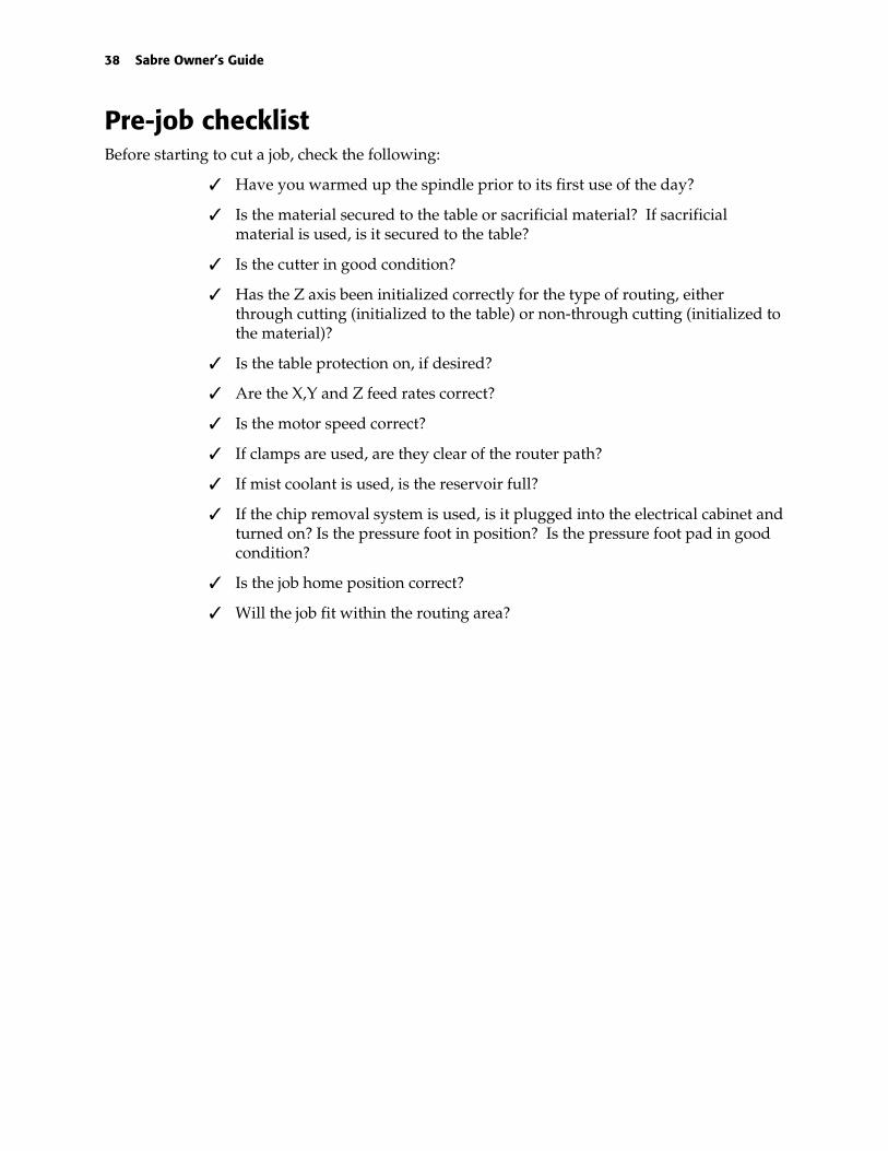
Pre-job checklistBefore starting to cut a job, check the following:
� Have you warmed up the spindle prior to its first use of the day?
� Is the material secured to the table or sacrificial material? If sacrificialmaterial is used, is it secured to the table?
� Is the cutter in good condition?
� Has the Z axis been initialized correctly for the type of routing, eitherthrough cutting (initialized to the table) or non-through cutting (initialized tothe material)?
� Is the table protection on, if desired?
� Are the X,Y and Z feed rates correct?
� Is the motor speed correct?
� If clamps are used, are they clear of the router path?
� If mist coolant is used, is the reservoir full?
� If the chip removal system is used, is it plugged into the electrical cabinet andturned on? Is the pressure foot in position? Is the pressure foot pad in goodcondition?
� Is the job home position correct?
� Will the job fit within the routing area?

Routing 39
Warming up the spindleFor optimum performance, warm up the spindle prior to its first use each day. The Sabrecontrols the process with an automated warm up sequence located in the Manual Feed Modemenu. There must be a tool loaded in the spindle during warm up. If you do not install a toolthe error message, Tool needed! appears on the Sabre display.
WARNING: Move the spindle toward the center of the table to ensure that it is asafe distance from the operator during the warm up procedure.
To warm up the spindle
1 Starting at the Status menu, press the down arrow key until you see:MAIN MENU 2A: Position controlB: Manual feedC: Configuration
2 Press B to select the Manual Feed menu. The display reads:MANUAL FEEDA: Manual feed modeB: Manual feed rateC: Spindle Air
3 Press A to select the Manual Feed Mode menu shown below.MANUAL FEED MODEA: Turn motor onB: Motor warmup
4 Press B to select Motor Warmup. The display reads:MOTOR WARMUPA: Start warmupB: Cancel
5 Press A to start the warm up sequence. Press B to cancel and return to the ManualFeed Mode menu.
MOTOR WARMUPA: Start warmupB: CancelTime Left: 0.0 min
The spindle automatically turns on and the Sabre displays a message counting down the timeleft in the warm up sequence. The spindle turns off when warm up is complete.
Holding down materialTo cut material safely and accurately, the material must be held down securely on the tablesurface. The more rigidly the material is held to the router table, the better the cut quality. Whenthe material is held rigidly, you will increase tool life and can increase X,Y feed rate.
The Sabre permits several ways of holding down the material: clamps, the T-Vac Option, tape,adhesive, or a combination of methods. It also accommodates use of sacrificial material. Clampscan be used to secure the edges of the material to the table. The T-Vac Option uses zoned

40 Sabre Owner’s Guide
vacuum to hold a wide range of material sizes onto the table surface and reduces the need foradhesive. Clamps may be used in combination with the T-Vac.
Sacrificial material may be placed under the material when through-cutting. The tool plungescompletely through the material and into the sacrificial material. Either clamps or the T-Vacmay be used to hold the sacrificial material down. Various methods may be used to secure amaterial to sacrificial material, such as double-sided tape and spray adhesive.
Which method you choose depends on the material you are cutting and whether you plan to cutthrough, cut to mask, leave a web, or engrave the surface.
Using clampsIf not using the T-Vac, use table clamps to secure the material or sacrificial material to the tablesurface. The clamp assembly consists of a clamp strap, a T-nut, and a knob-and-screw assembly.Six clamp assemblies are provided in the Sabre tool kit. Place the clamps at three corners of thematerial, leaving the start position corner free of clamps.
Clamps should always be used with materials with irregular surfaces, if the T-Vac Option is notpresent, or if the job is left unattended.
CAUTION: When using clamps, make sure they are positioned so that the routerwill not hit them during cutting. When cutting is unattended, make sure the clampsdo not interfere with the cutting operation. Serious damage may result if the routerhits a clamp during cutting.
To install clamps
1 Press the X and Y move keys to move the router carriage to the back of the table.
2 Place the material or sacrificial material on the table and position it so that the edges tobe clamped are near a T-slot.
3 Insert the knob-and-screw assembly through the clamp strap.
4 Place the T-nut into a T-slot as shown below. The bevels must be oriented so that theycontact the inside of the T-slot when tightened.

Routing 41
5 Insert the screw through the T-slot into the T-nut and tighten.
6 The clamp strap should be parallel to the material surface. If necessary, place a blockunder the back of the clamp to keep the clamp level. Turn the knob to tighten theclamp assembly.
Using the T-VacThe T-Vac reduces the need for sacrificial material by holding the material securely on the tablesurface without adhesive. With certain materials, you may wish to use sacrificial material orclamps in addition to the T-Vac. The T-Vac is ideal for materials that are flat. Do not use the T-Vac with very small materials, porous materials, or materials with irregular surfaces.
To use the T-Vac
1 The vacuum under any table slat may be turned on or off using the valve handles onthe vacuum manifold.
♦ The vacuum is on when the valve handle is vertical.
♦ The vacuum is off when the valve handle is horizontal.
2 Turn on the vacuum only under areas of the table covered by material.
3 To maximize vacuum, cover vacuum holes in table slats which have the vacuum onbut are not covered by material with non-porous material, especially for small parts.
4 Clamps are recommended if the job will be left unattended without the vacuum on.
Using sacrificial materialWhen cutting all the way through material, you may want to attach the material to sacrificialmaterial instead of to the table surface to protect the table surface from damage. No sacrificialmaterial is required when engraving.

42 Sabre Owner’s Guide
Follow these guidelines when choosing sacrificial material.
♦ Select a sacrificial material with a density similar to the material being cut.
♦ Medium Density Fiberboard (MDF) is a good sacrificial material since it is porousenough to allow the vacuum to draw through it and hold the workpiece in place.
♦ The best sacrificial materials are acrylic or pressed boards such as chip board andMasonite®. Acrylic is recommended over pressed board that contains glue. Glue isabrasive and can wear out cutter tips.
♦ Remove the protective paper from acrylic before using it as sacrificial material.
The material being cut determines how you attach material to sacrificial material. You can usedouble-sided tape, high-tack transfer tape, low-tack transfer tape, or spray adhesive. Theseproducts are available from your Gerber distributor, as well as through most industrial andoffice supply distributors.
Material hold down guidelinesFollow the general guidelines in this section. You may wish to adjust your procedures as yougain experience.
Wood and wood products
Examples of different kinds of wood that can be routed using the Sabre include MDF (mediumdensity fiberboard), plywood and other laminated woods, pine, poplar, redwood, cedar, oak,teak, walnut, cherry, and others.
Note: Use material that is as flat as possible. Holding warped material to the table is difficult.
To mount wood and wood products
1 Place the wood on the table in the desired location.
2 Use the vacuum shroud pressure foot assembly to assist in chip removal as well asextra holddown while cutting.
3 If using the T-Vac, try to use the vacuum holes to the best possible advantage. Keepany unused valves turned off. Block off any holes behind the material with a piece ofnon-porous material. If not using the T-Vac: Using the table clamps, place the clampsat three corners of the material leaving the start position corner free of clamps.
4 Initialize the tool from the material surface to cut into the material or initialize fromthe table to through cut (also called cut to mask).
5 When finished cutting, you will have a thin web of material remaining to hold theshapes being cut to the material. If you apply a paper mask to the back of the material,you automatically cut to the mask when you initialize from the table.
Metals and hardwood
♦ Use double-sided high-tack tape to secure the material directly to the table. This tape isnot affected by mist coolant and is suitable for securing metal. Cutting metal requireshigh cutting forces.

Routing 43
♦ When cutting rough textured wood, use both double-sided high-tack tape and sprayadhesive.
To mount thick aluminum or brass thicker than .125" (3.18 mm) without T-Vac
1 Use 1/8" (3.18 mm) acrylic sacrificial material.
2 Use double-sided high-tack tape to hold the material onto the sacrificial material. Besure to use aggressive tape to keep the shapes from shifting when they are cut free ofthe material.
3 Apply the tape so that all shapes are held securely to the sacrificial material.
4 Use clamps to secure the aluminum/acrylic assembly to the table.
To mount thick aluminum or brass thicker than .125" (3.18 mm) with T-Vac
Note: Do not use sacrificial material.
1 Make sure the material is relatively flat or that the T-Vac can accommodate any warpand hold the material securely.
2 Set up the job to leave a slight web (.005" - .008" (.127 mm - .203 mm)) uncut to keepthe shapes in place as they are cut free of the material. Use the ADJ DEPTH functionkey to adjust the depth during cutting as described on page 32.
Note: To remove the shapes from the aluminum material, remove the material from the tableand tap each shape with a rubber hammer. Deburr each shape with a file or burr tool.
To mount thin aluminum or brass and other thin metals less than .090" (2.29 mm)
Whenever cutting aluminum, holding down the material stiffly provides better cut quality andedge finish. Using the method described below will allow you to hold the aluminum stiffly tothe sacrificial material. You will cut all the way through the aluminum into the sacrificialmaterial leaving a clean edge. This also allows removal of the cut pieces from the sacrificialmaterial without bending the aluminum.
Note: 6061-T6 aluminum will give the best results.
1 Use 1/8" (3.18 mm) acrylic sacrificial material cut the same size as the metal. Removethe backing paper from one side.
2 Apply high-tack transfer tape to the back side of the metal. Be sure to squeegee thetape down well to achieve a good bond to the metal.
3 Apply high-tack spray adhesive (such as 3M Super 77) to the side of the acrylicwithout backing paper, as well as to the taped side of the metal. Follow themanufacturer’s application instructions.
4 Allow the spray to become tacky, then apply the material to the acrylic.
5 Use clamps or the T-Vac to hold down the aluminum/acrylic assembly.

44 Sabre Owner’s Guide
Acrylic sheet/PVC sheet and similar materials
Note: Do not use sacrificial material.
To mount acrylic sheet/PVC and similar materials
1 Use a sheet with backing paper on both sides of the sheet. The bottom sheet will allowyou to cut to mask and keep the shapes in place as they are cut free of the material.The top sheet will protect the surface from scratches. (If there is no backing paper,apply transfer tape as a mask.)
2 Position the material directly on the router table.
3 If using the T-Vac, turn on the necessary control valves and the T-Vac pump. If notusing the T-Vac, position the material on the table so that you can clamp at least threecorners. Do not use a clamp at the start position. Be careful to avoid the clamps whilerouting.
4 Set up the job to cut to mask. Cutting to the backing paper but not through the paperwill allow material to be held while shapes are cut out of material.
5 Use the ADJ DEPTH function key to change the depth during initialization asnecessary.
Setting speed and feedsYou can control the rate at which the Sabre performs cutting operations by adjusting the rateslisted below. See the Speed and Feeds Chart inserted at the back of this manual for specificinformation.
♦ Spindle speed in revolutions per minute (rpm)
♦ X,Y feed rate - the rate in inches per minute (ipm) at which the Sabre travels duringcutting (metric: millimeters per second (mmps))
♦ Z feed rate - the rate in inches per minute (ipm) at which the tool plunges into thematerial (metric: millimeters per second (mmps))
Changing spindle speedThe standard router motor (your chosen motor may differ) s equipped with a slide switch thatallows you to select the following speed settings:
♦ 10,000 rpm
♦ 13,000 rpm
♦ 16,000 rpm
♦ 19,000 rpm
♦ 21,000 rpm
The high frequency spindle speed can be set in ART Path or by using the control pad RPMfunction key. Refer to the ART Path and Auto-Carve User's Guide to set the RPM in the tool pathdialog boxes.

Routing 45
Overriding the X,Y feed rateYou can override the X,Y FEED RATE set in ART Path by a percentage of the established rate.The effect of various percentages entered from the Sabre control pad on a 50 ipm feed rate set inART Path is as follows:
% Override Actual Feed Rate
100 50 ipm
50 25 ipm
200 100 ipm
To adjust the X,Y Feed Rate
1 Press the PAUSE job control key and wait for the router to pause.
2 Press the FEED RATE function key. The display reads:SPEED/FEEDSA: Spindle SpeedB: X,Y feed rateC: Z feed rate
3 Press B. The display reads:X,Y Feed Rate
0100 %A: IncreaseB: Decrease
4 Press:♦ A to increase the feed rate♦ B to decrease the feed rate
5 The feed rate ranges from 1% to 1000%.
6 Press ENTER to record the change.
7 Press START to continue with the job at the new feed rate.
To override the Z feed rate
1 Press the PAUSE job control key.
2 Press the FEED RATE function key. The display reads:SPEED/FEEDSA: Spindle SpeedB: X,Y feed rateC: Z feed rate
3 Press C. The display reads:Z FEED RATE0100 %A: IncreaseB: Decrease
4 Press:♦ A to increase the Z feed rate♦ B to decrease the Z feed rate

46 Sabre Owner’s Guide
The range of valid values is 1% to 1000%.
5 Press ENTER to record the change.
6 Press START to continue with the job at the new feed rate.
Position controlIn addition to the move keys, which allow you to move the carriage and the tool, the Sabreprovides the following functions that allow you to control its position:
♦ Display the exact current position of the X, Y, and Z axes.
♦ Raise the tool (Z axis) all the way up (Z up).
♦ Return to the table orientation point (table 0,0).
To display position
Note: You cannot display position during routing.
1 Press the down arrow key until the display reads:MAIN MENU 2A: Position controlB: Manual feedC: Configuration
2 Press A to select the Position control menu. The display reads:POSITION CONTROLA: Position displayB: Z upC: Return to 0,0
3 Press A to select the Position display menu shown below.ABSOLUTE POSITIONx 000.000 iny 000.000 inz 000.000 in
4 Press ENTER repeated to return to the STATUS menu.
To raising the tool (Z up)
1 Press the Z UP function key to raise the tool, or press the down arrow key until thedisplay reads:
MAIN MENU 2A: Position controlB: Manual feedC: Configuration
2 Press A to select the Position control menu shown below.POSITION CONTROLA: Position displayB: Z upC: Return to 0,0
3 Press B to select Z up and raise the tool. Repeatedly press EXIT to return to theSTATUS menu.

Routing 47
Returning to table 0,0 (orientation point)
WARNING: The carriage will move quickly. Stand away from the router table.
CAUTION: Make sure the path to the lower left corner of the table is clear ofobstructions.
1 Press the down arrow key until the display reads:MAIN MENU 2A: Position controlB: Manual feedsC: Configuration
2 Press A to select the Position control menu shown below.POSITION CONTROLPosition displayZ upReturn to 0,0
3 Press C to select Return to 0,0. The carriage moves to the lower left corner and themessage display shows the Main menu.
Routing the jobTo rout a job:
♦ Send the job from ART Path to Sabre.
♦ Verify the job size and boundaries.
♦ Set job home (optional).
This section describes the sequence for routing with the Sabre without using the ATC. Fordetailed explanations of using ART Path, refer to the ART Path and Auto-Carver User’s Guide.
To rout a design
1 Import the design into ART Path and generate the tool paths.
2 Load the correct tool in the spindle. Sabre displays the Z Init Table menu to promptyou to initialize the tool to the table. See “Establishing a table surface reference” formore information.
Z INIT TABLEA: Initialize
3 Output the job from ART Path. Select Rout to send the job to the Sabre. When Sabrereceives the job, it displays:
STATUSSYSTEM: IdleJOB: Ready
4 If necessary, you can override the speed setting output from ART Path. Modify theRPM speed for the material and the tool you are using.
5 Press START once. The display shows:STATUS
MACHINE: Paused

48 Sabre Owner’s Guide
JOB: ReadyLoad Material
6 Press START again. Any Pre-position move set in ART Path occurs now. The displayshows:
STATUSMACHINE: PausedJOB: ReadyScrolling tool message
7 The following prompt appears on the control pad display:NOMINAL THICKNESS
0.500 inA: IncreaseB: Decrease
8 Verify that the nominal material thickness set in ART Path is correct. Do one of thefollowing:
♦ Press ENTER to accept the nominal thickness value. The control pad displays the SetActual Thickness menu.
CAUTION: Do not change the nominal thickness value sent from ART Path unlessit is wrong. The Nominal thickness value must be greater than or equal to the totaldepth entered in ART Path. If the values do not match, results will not be asexpected.
♦ Press A or B to change the nominal thickness. The material thickness you select mayrange from .063" to 6.000" in .063" increments (1.5 mm to 150 mm in 1.5 mmincrements.) Press ENTER to accept the nominal thickness value. The control paddisplays the Set Actual Thickness menu.
SET ACTUAL THICKNESSA: Use Last 0.489B: Use Nominal 0.500C: Do Material Init
9 Choose one of the following:
♦ Press A to accept the last thickness value as the current thickness value. This is helpfulwhen routing multiple jobs on the same work piece. The Sabre begins routing the job.
♦ Press B to use the nominal value for the current thickness value. Nominal thicknessvalues can be used when through-cutting the work piece. The Sabre begins routing thejob.
♦ Press C to perform a Z axis initialization to the material surface. You must establish amaterial surface reference when the job contains non-through cutting tool paths. Formore information on initializing to the material, see “Establishing material surfacereference.” The control pad displays:
Z INIT MATERIALA: Initialize

Routing 49
10 Initialize the tool to the material and press A. The control pad displays:MAIN MENU 1A: Z initB: Speeds/feedsC: Home
11 Press ENTER. The control pad displays:STATUS
SYSTEM: PausedJOB: ReadyScrolling tool message
12 Press START to rout the job.
The motor turns on. The router plunges quickly to its initialized height, then plunges into thematerial and begins cutting. After the tool path is complete, the Sabre pauses and prompts youto load the next tool. You must initialize the Z axis to the table and continue with the routingsequence as described above until all tool paths are complete.
Emergency stoppingPress the red emergency stop switch on either end of the router beam or on the control padbracket if routing must be stopped immediately in an emergency. The job terminatesimmediately and must be restarted.
CAUTION: If the tool is in the material when you press the emergency stop switch,it remains in the material. Before restarting the job, raise the tool to avoid breakingit.
Pausing and restarting routing
To pause routing
1 Press the PAUSE job control key.
Note: Travel may not stop immediately.
2 When the Sabre finishes routing the part of the job in its memory, travel stops, the toollifts, and the motion stops. At this point, you may move the carriage out of the way toinspect the job.
To continue after a pause
1 Press START once when you are ready to resume a paused job. The carriage returns tothe point where it was paused. The tool plunges and continues routing.
To stop routing
1 Press RESET. Travel stops immediately and the motor shuts off.
Note: Pressing RESET while a job is routing removes the job from the Plot Spooler or GQManager queue. To re-cut the job, you must send it again from ART Path.

50 Sabre Owner’s Guide
Verifying job size and boundariesJob boundaries cannot exceed the active cutting area of the table. If the job home positiontogether with a pre-position move causes the job to extend past the active cutting area, Job WillExceed Table Boundary will be displayed. Also, when using a pre-position move, that valuewill be added to the job size. Job boundaries for specific job types are defined as:
♦ All repeats are included within the boundary.
♦ Paneled jobs are treated as separate jobs. Each panel must fit within the active cuttingarea.
♦ Inplace repeats include the park position within the active cutting area.
Setting and changing job home positionThe job home position is the position on the router table where you want the job to start. Itcorresponds to the start position in the job data. Job home position may be set in the followingways:
♦ You can allow the tool position to be the job home position when you press START.
♦ You can set a pre-position move from the ART Path Output dialog box which willchange the start position.
♦ If you decide to change the job start position before you press the START button forthe third time, you can use the control pad move keys to move the tool to the newposition, thus changing the job start position.
To change job home
1 Press the X,Y move keys on the control pad to move the tool to the desired job home(start) position.
2 Press the Home function key and go to step 3 or press the down arrow key until thedisplay reads:
MAIN MENU 1A: Z initB: Speeds/FeedsC: Home
3 Press C to select the Home menu shown below.HOMEA: Return homeB: Set homeC: Undo home

Routing 51
4 Press A to move the tool to the current home position. To change the home position,press the X and Y move keys to move the tool to the desired position, then press B toset the new home position. To undo the new setting and return to the previous one,press C.
Displaying elapsed job timeThe Sabre now displays the Elapsed Job Time at the end of a job. Press any key to clear thedisplay. Elapsed Job Time is helpful when estimating job costs and times.
Manual routingThe Sabre allows you to make straight horizontal, or vertical cuts under manual control fromthe control pad, which is useful for cutting off sections of material. You cannot cut curves ordiagonals.
To set the feed rate for manual routing
1 Press the down arrow key until the display reads:MAIN MENU 2A: Position controlB: Manual feedC: Configuration
2 Press B to select the Manual feed menu. The display reads:MANUAL FEEDA: Manual feed modeB: Manual feed rateC: Spindle Air
3 Press B to select the Manual Feed Rate menu shown below.MANUAL FEED RATE0300 ipmA: IncreaseB: Decrease
4 Press A or B to change the feed rate, then press ENTER to record the setting.
5 Press the X and Y move keys to move the carriage to the point where you want to startcutting, usually to edge of the material.
6 Press A. The display reads:MANUAL FEED MODEA: Turn motor on/offB: Motor warmup
7 Press A to turn on the motor and the vacuum.
8 Press the Z move keys to lower the tool into the material.
9 Press the X and Y move keys to move the carriage.
10 Press the Z move keys to raise the tool.
11 Press A again to turn the motor off.

52 Sabre Owner’s Guide
Controlling the spindle air on ATC equipped machinesYou can turn on or turn off the spindle air from the Sabre control pad.
To control the spindle air
1 Starting at the Status menu, press the down arrow key until you see:MAIN MENU 2A: Position controlB: Manual feedC: Configuration
2 Press B to select the Manual Feed menu. The display reads:MANUAL FEEDA: Manual feed modeB: Manual feed rateC: Spindle Air
3 Press C to select the Spindle Air menu shown below. Press A to change the selectionfrom Spindle Air on or off.
SPINDLE AIR CONTROLA: Turn air on or off
4 Press ENTER to accept the change and SHIFT + EXIT or EXIT repeatedly to return tothe Status menu.

Routing 53
Changing motorsThe Sabre may be used with the standard 3¼ hp router, the High Frequency Spindle Option, theAutomatic Tool Changer Option, or the Engraving Option. Follow the procedures below tochange the router motor. Removing the pressure foot makes changing the motor easier. See“Removing the pressure foot assembly” on page 31 for directions.
To change motors
1 Shut off power to the Sabre by turning off the main power breaker on the electricalcabinet.
2 Disconnect the router motor power cord on the carriage.
3 Unhook and remove the side springs.
4 Loosen the four screws that secure the motor bracket to the carriage. Remove thelower spring brackets.
5 Two pins projecting from the bracket hold the bracket in place while the screws areremoved. Slide the bracket with the pins from the carriage.
6 Slide the new motor/bracket assembly into the holes for the pins.
7 Reinstall the two top mounting screws, then the two bottom screws and lower springbrackets.
8 Install the side springs.
9 Plug the power cord into the receptacle on the side of the carriage.

54 Sabre Owner’s Guide
Maintenance
This section provides guidelines for maintaining the Sabre router in good operating condition.Proper maintenance is based on daily inspection and daily and weekly cleaning.
Daily inspectionSabre Component Inspect For:
Entire machine surface Chips, mist coolant buildup
X and Y ways Debris
Lead screws Debris
Router motor carriage Debris
Mist coolant nozzle Coolant buildup
Mist coolant tank Coolant level
Electrical cabinet airfilter
Debris
Daily cleaningWARNING: Disconnect the Sabre from the AC power outlet before performing anycleaning procedure.
Recommended cleaning supplies♦ Vacuum
♦ Lint-free cloth
♦ Hand broom
♦ 1" (25 mm) nylon or natural bristle brush
♦ 2.5 mm and 4 mm hex head wrenches
♦ Light machine oil (3-IN-ONE®, Marvel™ Mystery oil, or 10 weight machine oil)

Maintenance 55
Table surface cleaningUse a hand broom to clean the router table surface after each operation, brushing away thechips from around the router motor and the work table. Use the lint-free cloth to wipe the tableclean.
X way cleaningThe X ways are the shafts located on the beam and under the beam behind the cover on whichthe router motor carriage moves.
To clean the X way
1 Clean the X ways by wiping them with a lint-free cloth.
2 Lubricate the X ways with light machine oil.
Y way cleaningThe Y ways are the shafts on which the beam moves. There is one Y way on each side of therouter running the length of the router.
To clean the Y way
1 Clean the Y ways by wiping them with a lint-free cloth.
2 Lubricate the Y ways with light machine oil.
Lead screw cleaning
CAUTION: Do not oil or lubricate the lead screws in any way. LURBRICATINGTHE LEAD SCREW WILL CAUSE DAMAGE.

56 Sabre Owner’s Guide
The lead screws are located along the width of the router motor carriage below the ways, on theZ axis, and beneath the center front of the router.
Use a soft, clean brush to remove debris from the lead screws.
Electrical cabinet air filter cleaning
To clean the electrical air filter
1 Snap off the cover of the air filter from the side of the electrical cabinet.
2 Remove the air filter from the cover.
3 Vacuum the filter thoroughly to remove dust and debris.
4 Replace the filter in the cover.
5 Reinstall the cover on the electrical cabinet.
Weekly maintenanceWeekly maintenance consists of cleaning and lubricating the Z ways.
Z axis lubricationThe Z axis ways are located on either side of the router motor.
To lubricate the Z axis
1 If the motor contains a tool, remove it.
2 Power up.
3 Press the Z axis down arrow keys on the control pad to lower the router motor to itslowest position.
4 Clean the upper part of the Z axis ways with a lint-free cloth.
5 Lightly oil the way with light machine oil.

Maintenance 57
6 Press the Z axis up arrow key to raise the router motor to its highest position.
7 Clean the lower part of the Z axis ways with a lint-free cloth.
8 Lightly oil the way with light machine oil. Do not oil the Z axis lead screw.
CAUTION: Do not oil the Z axis lead screw located between the Z axis ways.OILING THE LEAD SCREW WILL RESULT IN DAMAGE.

58 Sabre Owner’s Guide
Troubleshooting
This section contains general guidelines for troubleshooting the Sabre router. For service,contact your Gerber distributor or the Gerber Router Technical Support Group at 860-528-1028.
SYMPTOM DIAGNOSTICS CAUSES SOLUTIONS
~Check Power CordConnection.
~Power Cord Disconnected /Damaged.
~Reconnect Power Cord. Repair/replace asrequired.
SYSTEMWILL NOTPOWER UP ~No 230VAC (+/- 10%)
Single Phase, 30A availableat Outlet for Sabre ElectricalTower.
~Breaker(s) in Sevice Paneltripped/defective.
~Reset breaker(s) in Service panel -repair/replace as required.
~Wiring problem to or in theoutlet supplying A/C to theElectrical Tower.
~Check supply outlet and receptacle wiring -repair/replace as required.
~Correct A/C is available toSabre Electrical TowerCircuit Breaker tripsimmediately at power-up.
~Emergency Stop SwitchCircuit active.
~Check for wiring/connector problem throughthe circuitry for the three Emergency StopSwitches.
~Problem with Transzorb inElectrical Tower Power InputPanel.
~Check Transzorb on TB3 of Power InputPanel. Transzorb is attached between lugs 3& 7 on the "A" side of TB3. NOTE: Systemcan be operated with Transzorb disconnectedfor test purposes.
~Problem with ElectricalTower Circuit BreakerAssembly.
~Check Electrical Tower Circuit BreakerAssembly. Replace as necessary.
~No A/C into the LF1 LineFilter in Electrical TowerPower Input Panel
~Problem with A/C feed wiresto LF1. Problem with fuse F2.
~Check LF1 input wiring from TB3-4B andTB3-8B. Repair/replace as required. CheckF2 fuse - replace as required with fuse ofsame rating.
~No A/C from the LF1 LineFilter in Electrical TowerPower Input Panel to TB1on the Power Supply.
~Problem with A/C feed wiresbetween LF1 and TB1 ofPower Supply. Problem withLF1 Line Filter.
~Repair/replace A/C feed wires between LF1and TB1 of Power Supply. Replace LF1 LineFilter.
~Correct A/C is available atTB1 on the Power Supply.
~Problem with A/C feed wiresbetween TB1 and PowerSupply.
~Repair/replace A/C feed wires between TB1and Power Supply.
~Problem with dc output ofPower Supply
~Test for +5 volts dc output at connection J1-1 of Power Supply regulator Board. ReplacePower Supply if no +5 volts dc present.
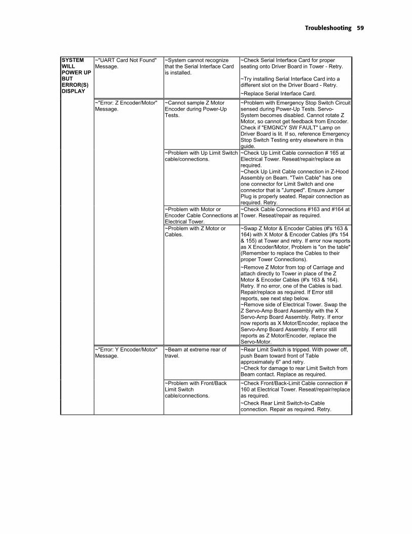
Troubleshooting 59
~"UART Card Not Found"Message.
~System cannot recognizethat the Serial Interface Cardis installed.
~Check Serial Interface Card for properseating onto Driver Board in Tower - Retry.
~Try installing Serial Interface Card into adifferent slot on the Driver Board - Retry.
SYSTEMWILLPOWER UPBUTERROR(S)DISPLAY ~Replace Serial Interface Card.
~"Error: Z Encoder/Motor"Message.
~Cannot sample Z MotorEncoder during Power-UpTests.
~Problem with Emergency Stop Switch Circuitsensed during Power-Up Tests. Servo-System becomes disabled. Cannot rotate ZMotor, so cannot get feedback from Encoder.Check if "EMGNCY SW FAULT" Lamp onDriver Board is lit. If so, reference EmergencyStop Switch Testing entry elsewhere in thisguide.
~Problem with Up Limit Switchcable/connections.
~Check Up Limit Cable connection # 165 atElectrical Tower. Reseat/repair/replace asrequired.~Check Up Limit Cable connection in Z-HoodAssembly on Beam. "Twin Cable" has oneone connector for Limit Switch and oneconnector that is "Jumped". Ensure JumperPlug is properly seated. Repair connection asrequired. Retry.
~Problem with Motor orEncoder Cable Connections atElectrical Tower.
~Check Cable Connections #163 and #164 atTower. Reseat/repair as required.
~Problem with Z Motor orCables.
~Swap Z Motor & Encoder Cables (#'s 163 &164) with X Motor & Encoder Cables (#'s 154& 155) at Tower and retry. If error now reportsas X Encoder/Motor, Problem is "on the table"(Remember to replace the Cables to theirproper Tower Connections).
~Remove Z Motor from top of Carriage andattach directly to Tower in place of the ZMotor & Encoder Cables (#'s 163 & 164).Retry. If no error, one of the Cables is bad.Repair/replace as required. If Error stillreports, see next step below.~Remove side of Electrical Tower. Swap theZ Servo-Amp Board Assembly with the XServo-Amp Board Assembly. Retry. If errornow reports as X Motor/Encoder, replace theServo-Amp Board Assembly. If error stillreports as Z Motor/Encoder, replace theServo-Motor.
~"Error: Y Encoder/Motor"Message.
~Beam at extreme rear oftravel.
~Rear Limit Switch is tripped. With power off,push Beam toward front of Tableapproximately 6" and retry.~Check for damage to rear Limit Switch fromBeam contact. Replace as required.
~Problem with Front/BackLimit Switchcable/connections.
~Check Front/Back-Limit Cable connection #160 at Electrical Tower. Reseat/repair/replaceas required.~Check Rear Limit Switch-to-Cableconnection. Repair as required. Retry.

60 Sabre Owner’s Guide
~"Error: Y Encoder/Motor"MessageContinued
~Problem with rear LimitSwitch.
~Disconnect Rear Limit Switch from Cable.Fabricate and install a "jumper" in the Cableconnection in place of the Limit Switch. Retry.If no error, replace Rear Limit Switch.
~Problem with Motor orEncoder Cable Connections atElectrical Tower.
~Check Cable Connections #158 and #159 atTower. Reseat/repair as required.
SYSTEMWILLPOWER UPBUTERROR(S)AREDISPLAY- Continued ~Problem with Y Motor or
Cables.~Swap Y Motor & Encoder Cables (#'s 158 &159) with X Motor & Encoder Cables (#'s 154& 155) at Tower and retry. If error now reportsas X Encoder/Motor, Problem is "on the table"(Remember to replace the Cables to theirproper Tower Connections).~Remove Y Motor from housing and attachdirectly to Tower in place of the Y Motor &Encoder Cables (#'s 158 & 159). Retry. If noerror, one of the Cables is bad.Repair/replace as required. If Error stillreports, see next step below.~Remove side of Electrical Tower. Swap theY Servo-Amp Board Assembly with the XServo-Amp Board Assembly. Retry. If errornow reports as X Encoder/Motor, replace theServo-Amp Board Assembly. If error stillreports as Y Encoder/Motor, replace theServo-Motor.
~"Error: X Encoder/Motor"Message
~Carriage at extreme right oftravel.
~Right Limit Switch is tripped. With power off,push Carriage toward center of Tableapproximately 6" and retry.
~Check for damage to Right Limit Switchfrom Carriage contact. Replace as required.
~Problem with Left/Right LimitSwitch cable/connections.
~Check Left/Right-Limit Cable connection #156 at Electrical Tower. Reseat/repair/replaceas required.
~Check Right Limit Switch-to-Cableconnection. Repair connection as required.Retry.
~Problem with Right LimitSwitch.
~Disconnect Right Limit Switch from Cable.Fabricate and install a 'jumper' in the Cableconnection in place of the Limit Switch. Retry.If no error, replace Right Limit Switch.
~Problem with Motor orEncoder Cable Connections atElectrical Tower.
~Check Cable Connections #154 and #155 atTower. Reseat/repair as required.
~Problem with X Motor orCables.
~Swap X Encoder & Motor Cables (#'s 154 &155) with Z Encoder & Motor Cables (#'s 163& 164) at Tower and retry. If error now reportsas Z Encoder/Motor, Problem is "on the table"(Remember to replace the Cables to theirproper Tower Connections).

Troubleshooting 61
~"Error: XEncoder/Motor" Message
Continued
~Problem with X Motor orCables
Continued
~Remove X Motor from housing and attachdirectly to Tower in place of the X Motor &
Encoder Cables (#'s 154 & 155). Retry. If noerror, one of the Cables is bad.
Repair/replace as required. If Error stillreports, see next step below.
SYSTEM WILLPOWER UP
BUTERROR(S)
ARE DISPLAY- Continued
~Remove side of Electrical Tower. Swap theX Servo-Amp Board Assembly with the Y
Servo-Amp Board Assembly. Retry. If errornow reports as Y Encoder/Motor, replace the
Servo-Amp Board Assembly. If error stillreports as X Encoder/Motor, replace the
Servo-Motor.
~Keyboard Displayremains in the
"Copyright….." ScrollMode.
~Tower cannot successfullycomplete the built-in power-up
self checks.
~Check/reseat all connections on Boards inElectrical Tower. Double-check the seat of
the Spindle DUART card. Retry. If no change,remove DUART and retry. If "Orient"
message appears, replace DUART Card. If"Orient" message still doesn't appear, replace
the Control Board.
SYSTEM WILLPOWER UP
BUTKEYBOARD
WILL NOT GOTO THE
"ORIENT"MESSAGE ~Problem with Keyboard
Table Cable connection #151at Tower, or 151 harness
connections to Control Board.
~Check #151 connection. Repair/replace asneeded. Check harness connections at
Control Board. Reseat as required.
~Problem with KeyboardTable Cable connection at
Keyboard Support - or -problem with Keyboard "curlycable" to Support connection.
~Check all Keyboard connections atKeyboard Support. Repair/replace as needed.
~Problem with KeyboardTable Cable - or - Keyboard
"curly cable".
~Attach Keyboard directly to #151 Towerconnection. Retry. If "Orient" message
appears, replace Keyboard Table Cable. If nochange, replace Keyboard Assembly.
~"Error: X Axis" appearson Keyboard Display.
~X Axis attempts to Orientbefore reaching left limit
switch, moves slightly to right,then displays error message.
~Left limit switch or connection problem.Repair/replace as required.
PROBLEMOCCURSDURING
ORIENTATION~X Axis attempts to move
toward left, stops, thendisplays error message
~Some type of mechanical obstructioninhibiting axis movement. Check for anydebris, binding of mechanical parts, etc.
~"Error: Y Axis" appearson Keyboard Display.
~Y Axis attempts to Orientbefore reaching left limit
switch, moves slightly to rear,then displays error message.
~Front limit switch or connection problem.Repair/replace as required.
~Y Axis attempts to movetoward front, stops, thendisplays error message
~Some type of mechanical obstructioninhibiting axis movement. Check for anydebris, binding of mechanical parts, etc.
~"Error: Z Axis" appearson Keyboard Display.
~Z Axis attempts to Orientbefore reaching top limitswitch, moves slightly
downward, then displays errormessage.
~Top limit switch or connection problem.Repair/replace as required.
~Z Axis attempts to movetoward top, stops, thendisplays error message
~Some type of mechanical obstructioninhibiting axis movement. Check for anydebris, binding of mechanical parts, etc.
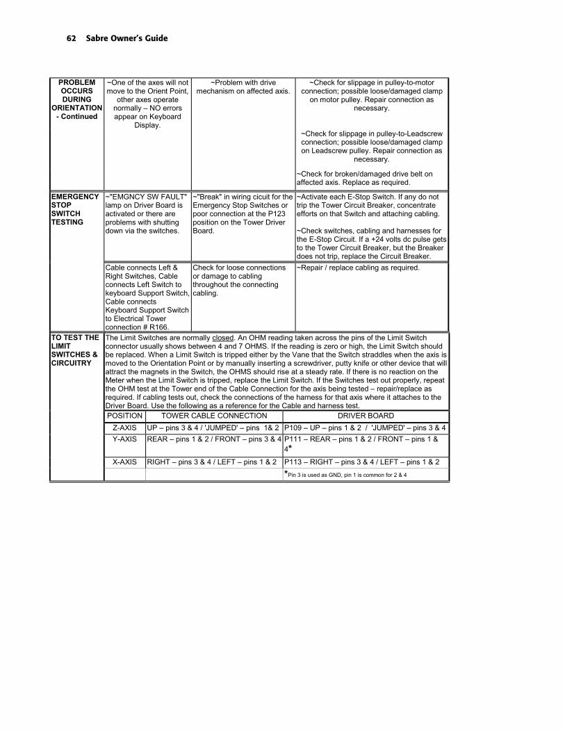
62 Sabre Owner’s Guide
~One of the axes will notmove to the Orient Point,
other axes operatenormally – NO errorsappear on Keyboard
Display.
~Problem with drivemechanism on affected axis.
~Check for slippage in pulley-to-motorconnection; possible loose/damaged clamp
on motor pulley. Repair connection asnecessary.
PROBLEMOCCURSDURING
ORIENTATION- Continued
~Check for slippage in pulley-to-Leadscrewconnection; possible loose/damaged clampon Leadscrew pulley. Repair connection as
necessary.
~Check for broken/damaged drive belt onaffected axis. Replace as required.
EMERGENCYSTOPSWITCHTESTING
~"EMGNCY SW FAULT"lamp on Driver Board isactivated or there areproblems with shuttingdown via the switches.
~"Break" in wiring cicuit for theEmergency Stop Switches orpoor connection at the P123position on the Tower DriverBoard.
~Activate each E-Stop Switch. If any do nottrip the Tower Circuit Breaker, concentrateefforts on that Switch and attaching cabling.
~Check switches, cabling and harnesses forthe E-Stop Circuit. If a +24 volts dc pulse getsto the Tower Circuit Breaker, but the Breakerdoes not trip, replace the Circuit Breaker.
Cable connects Left &Right Switches, Cableconnects Left Switch tokeyboard Support Switch,Cable connectsKeyboard Support Switchto Electrical Towerconnection # R166.
Check for loose connectionsor damage to cablingthroughout the connectingcabling.
~Repair / replace cabling as required.
TO TEST THELIMITSWITCHES &CIRCUITRY
The Limit Switches are normally closed. An OHM reading taken across the pins of the Limit Switchconnector usually shows between 4 and 7 OHMS. If the reading is zero or high, the Limit Switch shouldbe replaced. When a Limit Switch is tripped either by the Vane that the Switch straddles when the axis ismoved to the Orientation Point or by manually inserting a screwdriver, putty knife or other device that willattract the magnets in the Switch, the OHMS should rise at a steady rate. If there is no reaction on theMeter when the Limit Switch is tripped, replace the Limit Switch. If the Switches test out properly, repeatthe OHM test at the Tower end of the Cable Connection for the axis being tested – repair/replace asrequired. If cabling tests out, check the connections of the harness for that axis where it attaches to theDriver Board. Use the following as a reference for the Cable and harness test.POSITION TOWER CABLE CONNECTION DRIVER BOARD
Z-AXIS UP – pins 3 & 4 / 'JUMPED' – pins 1& 2 P109 – UP – pins 1 & 2 / 'JUMPED' – pins 3 & 4
Y-AXIS REAR – pins 1 & 2 / FRONT – pins 3 & 4 P111 – REAR – pins 1 & 2 / FRONT – pins 1 &4*
X-AXIS RIGHT – pins 3 & 4 / LEFT – pins 1 & 2 P113 – RIGHT – pins 3 & 4 / LEFT – pins 1 & 2
*Pin 3 is used as GND, pin 1 is common for 2 & 4

Troubleshooting 63
MISC.ERRORS
~"Error: X Axis", "Error: YAxis" – or - "Error: ZAxis".
~Limit switch tripped beforeaxis reached it.
~Tower sensed erroneous trip from limitswitch before axis reached it. Faulty switch,cable or connection.
~Axis cannot move to nextposition.
~Mechanical obstruction to movement of axis.Check for debris wedged betweencomponents, Vacuum Shroud Pressure Footcatching in cut line, etc.
~Servo-Amp overload. ~Drag on axis. Low dc volts to Servo-Amp.Excessive Positioning Rate, ExcessiveVacShroud pressure against material, etc.
~Tower sensed problem in E-Stop circuitry.
~Tower sensed loss of E-Stop Circuit, shutdown Servo-Amp power circuit. Cannot rotatemotor to generate encoder signals. Check &repair E-Stop components as required.
~"Error: XEncoder/Motor""Error: Y Encoder/Motor"or "Error: Z coder/Motor".
~Tower sensing insufficient orexcess Encoder counts.
~Motor, Encoder or wiring problem.
~Rear, Right or "Jumped" (Z) Limit Switchsignal to Tower during power-up.
~Tower sensed loss of E-Stop Circuit, shutdown Servo-Amp power circuit. Cannot rotateMotor to generate Encoder signals. Check &repair E-Stop components as required.
~"Error: X PolarityReversed""Error: Y PolarityReversed" or "Error: ZPolarity Reversed".
~Encoder count feedbackindicates backward motion.
~Check Limit Switch and cabling in theopposite direction of travel for the affectedaxis. A signal from the (-) Limit Switch whilethe axis is travelling in the (+) direction willgenerate this error code.
~"Error: Fault in X Axis""Error: Fault in Y Axis" or"Error: Fault in Z Axis".
~Motor Servo Amplifierproblem.
~Check Servo-Amp Board, circuit & wiring forthe affected axis. Repair/replace as required.
~"Spindle I/O Failure" ~Tower cannot communicatewith Spindle Motor Controller.
~Spindle Controller not powered on.
~Serial cable or DUART Card harness isdisconnected or faulty.
~DUART Card faulty. Move the harness fromP-2 to P-3 connector and retry.
~Spindle Controller in error condition. Refer toManual in Controller for error diagnostic.
~"Error: Interrupt [x]" - xbeing a number
~Tower sensed a problemoutside it's programming andcannot identify it.
~Reset System and retry. RepeatedInterrupts may require Control Boardreplacement.
~"Error: Plot DataCommand"
~Tower received commands inunknown format.
~Job type must be set to "GERBER" in SabreSetup Menu, page 3.
~Sabre firmware and ART Path Softwaremust be compatible.
~"Error: Invalid Code x" ~Illegal G-Code commandreceived.
~Job type must be set to "G-CODES" inSabre Setup Menu, page 3.
G-CODESPECIFICERRORS ~"Error: Table Bounds
Violation" (followed by Xand Y coordinates)
~G-Code command attemptedto move one or more axesoutside of active cutting areaof table.
~Modify G-Code job to ensure all movementis within the active cutting area of the table.

64 Sabre Owner’s Guide
Error Messages
The following chart contains Sabre error message, possible causes, and suggested remedies. Ifyou need additional assistance, contact your Gerber distributor or the Gerber Router TechnicalSupport Group at860-528-1028.
Error Cause Remedy“ATC AIR PRESSURE” Air pressure drops below
(approximately) 85 psi atsensor.Faulty pressure sensor
Boost air pressure greaterthan 100 psi as indicated ongage.Replace pressure sensor.
“ATC ARM: arm sensorfailure (both on)”
ATC ‘arm out’ sensor and ‘armin’ sensor are both active.
Check sensors and wiring.
“ATC ARM: between
MOVE IT OUT BY HAND”
ATC arm is stopped withoutfully extending or retracting.
Disable ATC, then movearm off table manually.Check air connections.Check sensors and wiring.Check Mechanicalconnections for air cylinderand ‘shock absorber’.
“ATC ARM: in table
MOVE IT OUT BY HAND”
ATC arm is stopped withoutfully retracting.
Disable ATC, then movearm off table manually.Check air connections atATC arm.Check sensors and wiring.Check Mechanicalconnections for air cylinderand ‘shock absorber’.
“ATC SPINDLE ON” Attempt to turn spindle ONwith no tool.
Install tool before turningspindle on.Check Clampsensor/wiring.Check Tool presencesensor/wiring.
“BAD TABLE INIT” Material surface is below tablesurface.
Re-initialize tool with TableInit.
“CAN'T FIND THE ATC DISKHOME LOCATION”
ATC position 1 sensor did notget activated after attemptingto rotate 11 tool positions.
Check sensors and wiring.

Error Messages 65
Error Cause Remedy“CAN'T MOVE THE ATC DISKTO NEW LOCATION”
ATC position movementsensor did not get activated.
Check sensors and wiring.Check disk motor andwiring.
“can't close the door”
“can't engage safety”
“can't grab”
“can't move arm in”
“can't move arm out”
“can't open door”
“can't release tool”
“can't send speed request”
“can't spin disk”
“can't stop spindle”
“can't turn on cone”
“can't undo safety”
“can't w84 grab”
“can't w84 release”
Communication lost with ATCcontroller.
Check wiring.Power cycle tower.
“**Clamp Grab Error!”
“**Clamp Release Error!”
Clamp/unclamp detectionsensor did not activate whenexpected.
Check spindle clampsensor/wiring.
“E2 NOT FOUND ERROR” Not used Not used
“E2 NOT WORKING” Failure in nonvolatile memory. Return processor board forrepair.
“E2 TYPE COULD NOT BEDETERMINED VALUES WILLNOT BE SAVED”
Failure in nonvolatile memory– could not identify the type ofnon-volatile memory.
Return processor board forrepair.
“E2 WEAR OUT WARNINGthe system will not be ableto save it's settings.”
Failure in nonvolatile memory– could not write tononvolatile memory.
Return processor board forrepair.
“ENCODER NOT ZERO” X, Y, or Z position encoder isnot properly initialized atpower-up.
Check encoders.
“ERROR: can't talk to theATC Controller!”
Communication lost with ATCcontroller.(This may occur even on non-ATC jobs because ATC is usedto obtain spindle status).
Check wiring. Power cycletower.
“ERROR: Interrupt N” An Interrupt occurred that thefirmware can’t handle.Interrupt ID is N.
Check processor board forhardware problems.
“ERROR: Invalid code X” Illegal G-Code commandreceived.
Verify job type is G-Codeand not “Gerber”.Use only supported G-codes.
“ERROR: Spindle speedchange failure”
Not used. Not used.

66 Sabre Owner’s Guide
Error Cause Remedy“ERROR: Table BoundsViolation -X” (or +X, -Y, +Y)
G-code command attemptedto move outside of table activejob area.
Modify job so that allmovement stays withinactive job area.
“Error: Table protect” Depth of cut will cut into tablesurface.
Adjust depth of cut ormaterial thickness.Turn Table Protect OFF.
“FAULT IN X AXIS”
“FAULT IN Y AXIS”
“FAULT IN Z AXIS”
Motor servo amplifier fault. Check servo amplifierwiring/circuitry.
“PLOT DATA COMMAND” Illegal host GSPGL commandreceived.
Verify job type is “Gerber”.Make sure ART Path versionis compatible with routerversion.
“SPINDLE I/O FAILURE” Spindle Controller is notturned on.Attempt to turn on spindlewithout a tool.Spindle Controller failure.
Make sure spindle controlleris on.Install tool before turning onspindle.Check spindle controllererror codes.
“UART Card Not Found” Could not locate UART card. Make sure UART card isinstalled firmly intoconnector and that allconnections are properlymade.
“UART OVERRUN” Host communication notresponding to flow control.
Make sure hostcommunication serial port isconfigured for proper flowcontrol.
“X AXIS”
“Y AXIS”
“Z AXIS”
Limit switch was tripped.Could not move to 0,0 positionwhile Orienting.Servo amplifier exceededmaximum position error.
Power cycle and re-orientrouter.Check for obstruction to axismovement.Do not move carriagebeyond active job area.Check Emergency Stopcable/wiring.
“X ENCODER/MOTOR”
“Y ENCODER/MOTOR”
“Z ENCODER/MOTOR”
Encoder count indicatesinsufficient or excess motion.
Checkwiring/encoder/motor.Ensure that rear and/orright Limit Switches are notengaged at power-up orhave failed during job.Check Emergency Stopcable/wiring.

Error Messages 67
Error Cause Remedy“X POLARITY REVERSED”
“Y POLARITY REVERSED”
“Z POLARITY REVERSED”
Encoder count indicatesbackward motion
Check wiring.Test Limit Switch(es) for thataxis. A failed limit switchopposite travel direction willresult in the Tower receivinginfo that registers as motionin reverse of command.
Beep Codes Cause Remedy1 beep Flash memory not loaded Check Flash memory.
2 beeps RAM error Check RAM.
3 beeps Hardware Board error (incorrectlyreads a ‘known’ I/O address)
Replace CPU board.
4 beeps Flash write error Check Flash memory.
5 beeps Can’t communicate with keyboard Check keyboard and connections.
6 beeps not used
7 beeps Servo system Axis error See remedies for Axis errorsabove.
8 beeps Multifunction Peripheral chiperror
Replace CPU board.
9 beeps FW system error This could be caused by a varietyof problems. The most likelyproblems are bad RAM or faultyCPU board.

68 Sabre Owner’s Guide
Options
This section provides an overview of the options, which may be purchased with the Sabre.Refer to the section “Using the T-Vac” for more information. Information on other options’ usesare described in the user guide provided with each option. The options discussed in this sectionare:
♦ High Frequency Spindle Option
♦ Mist Coolant
♦ T-Vac
♦ Engraver
♦ Automatic Tool Changer
High Frequency Spindle OptionThe optional High Frequency Spindle replaces the standard 3¼ hp router. It provides quiet,variable-speed operation up to 24,000 rpm. The speed is selected from the control pad or in ARTPath.
The Speed Controller is contained in a NEMA 12 housing which protects it from the cuttingdebris. The Speed Controller stands on the floor near the Sabre.
Mist Coolant OptionThe Mist Coolant Option sprays a fine lubricant mist on the cutting tool to cool and lubricate itwhen cutting metals such as aluminum or brass. It is not used when cutting non-metallicmaterials such as wood or plastic.

Options 69
Note: The Mist Coolant Option cannot be used at the same time as the Chip Removal Systemor the Engraving Option.
Note: The Mist Coolant System requires a compressed air supply of 80 to100 psi.
T-Vac OptionThe T-Vac Option uses vacuum to hold a workpiece easily and securely on the Sabre routingsurface. It provides seven individually controlled vacuum zones on the router table to holddown a wide range of workpiece sizes. Depending on the material and the job, the T-Vac mayeliminate the need for clamps, adhesive, and sacrificial material, thus maximizing table area andminimizing setup time.
If your system was ordered with the T-Vac Option, the valves and manifold are installed at thefactory and all pipes and fittings required to connect to the vacuum pump are supplied with theSabre. A separately purchased vacuum pump and filter are required. Pump and filterspecifications are available from your Gerber distributor.
Engraver and Engraver Vacuum OptionsThe Engraver Option provides increased engraving accuracy from its floating Z axis. It alsoallows for quick tool changes by letting you initialize several tools before locking the Z axis.
A specially designed Engraver Vacuum Option can be separately purchased to clean debrisfrom the engraving area during operation. The Engraver Vacuum Option is a quiet,conveniently-sized system designed for use with the Engraving Option to clean debris from thetable and engraving area.
Automatic Tool Changer OptionThe Automatic Tool Changer (ATC) option increases routing efficiency by performing toolchanges during a routing job. A rotating turret holds up to 10 tool holders with tools that areautomatically swapped in and out of the 10 hp ATC spindle when the job calls for a tool change.
The ATC is attached to the side of the router table, requiring only a couple of square feet ofadditional floor space. It can be added in the field.

70 Sabre Owner’s Guide
Specifications
Specification Sabre 404 Sabre 408
Active cutting area 54"x 54"(1370 mm x 1370 mm)
54" x 100"1370 mm x 2540 mm
Overall size 69" x 75"(1750 mm x 1900 mm)
69" x 123"(1750 mm x 3120 mm)
Weight 750 lb. (340 Kg) 1,000 lb. (453 Kg)
Maximum materialthickness
4.4" (110 mm) 4.4" (110 mm)
Maximum material width 59" (1500 mm) 59" (1500 mm)
Z axis travel 7.5" (190 mm) 7.5" (190 mm)
X,Y feed rate 600 ipm (250 mm/sec) 600 ipm (250 mm/sec)
Z feed rate 300 ipm (125 mm/sec) 300 ipm (125 mm/sec)
Maximum positioning rate* 1300 ipm (590 mm/sec) 1300 ipm (590 mm/sec)
Resolution 0.000078" (0.0019 mm) 0.000078" (0.0019 mm)
Drive system Anti-backlash lead screw Anti-backlash lead screw
Controller/motors 32-bit servo 32-bit servo
*At nominal power

Index 71
IndexA
Acceleration, setting............................... 20Acrylic, routing....................................... 48Active cutting area ........................... 10, 54Actual material thickness...................... 32Adjust depth key.............................. 15, 37AI format ................................................... 8Aluminum, routing................................ 47Arrow keys.............................................. 15ART Path ................................................... 9ATC.......................................................... 73Automatic Tool Changer....................... 73Axes of movement ................................... 9
BBoundaries .............................................. 54Brass, routing.......................................... 47
CChecklist, pre-job.................................... 42Chip removal system......................... 8, 29
using .................................................... 30Clamps..................................................... 44Cleaning................................................... 58
electrical cabinet................................. 60lead screw ........................................... 59table surface........................................ 59X way................................................... 59Y way................................................... 59
Collets ...................................................... 25Configuration settings ........................... 16Control pad ......................................... 7, 13
key functions ...................................... 14Customer support .................................... 2Cutting
non-through............................ 10, 31, 32through.................................... 10, 31, 32tools...................................................... 25
DDaily inspection...................................... 58Data type ................................................. 24Default configuration settings.............. 16Design programs...................................... 8Display language, changing ................. 18DXF format................................................ 8
EElectrical cabinet....................................... 6Emergency
power switch ........................................ 7stopping............................................... 53
Engraver option...................................... 73EPS format................................................. 8Error messages........................................ 68
FFast key.................................................... 15FastFacts .................................................... 2Feed key................................................... 15Feed rate .................................................. 49
overriding ........................................... 15File formats ............................................... 8Firmware revision .................................. 11Function keys.......................................... 15
GG Code job............................................... 24Ground strap cable................................... 8
installing.............................................. 29
HHardwood, routing................................ 46High frequency spindle
option................................................... 72selecting............................................... 12
Holding down material ......................... 43Home key .......................................... 10, 15HPGL format ............................................ 8
IInitialization gage............................. 34, 35Initialize
from material surface ........................ 15from table surface .............................. 15
InitializingZ axis.............................................. 10, 52
Inplace repeats........................................ 54
JJob
boundaries .......................................... 54control keys......................................... 14data type.............................................. 24
72 Sabre Owner’s Guide
stopping............................................... 53Job home position
and job size ......................................... 54control pad key................................... 15defined................................................... 9returning to......................................... 21setting .............................................. 9, 54
LLanguage, changing............................... 18LED indicators .......................................... 6Lubricating, Z axis ................................. 60
MMachine, selecting.................................. 11Main power switch .................................. 6Maintenance............................................ 58
daily cleaning ..................................... 58daily inspection .................................. 58weekly ................................................. 60
Manual routing....................................... 55Mat milling.............................................. 37Material
hold down guidelines........................ 46holding down ..................................... 43Z init key ............................................. 15
Material surface reference......... 32, 35, 53MATL Z INIT key .................................. 35Measurement units ................................ 19Menus
control keys......................................... 15selection keys...................................... 14using .................................................... 14
Message displays.................................... 15Messages.................................................. 68Metal, routing ......................................... 46Mist Coolant Option ........................ 29, 72Motor
changing.............................................. 56selecting............................................... 12
NNominal material thickness ............ 31, 52
OOptions .................................................... 72Orientation point................................ 9, 51Orienting the system........................ 12, 43Override
X,Y feed rate ................................. 15, 49Z feed rate ........................................... 49
PPaneled jobs ............................................ 54Park position........................................... 54Pause key................................................. 14Pausing a job ........................................... 53Pen tool .................................................... 28Phone numbers......................................... 2Position, displaying ............................... 50Positioning rate, changing .................... 21Power switch............................................. 6Power up
after firmware revision...................... 11normal ........................................... 11, 12tests ...................................................... 13
Pre-job checklist...................................... 42Pre-position............................................... 9Pressure foot ....................................... 8, 30
changing pads .................................... 31PVC sheets, routing ............................... 48
RReset key............................................ 13, 14Restarting a job ....................................... 53Return 0,0 key ......................................... 15Router
changing motors ................................ 56selecting............................................... 11spindle, selecting................................ 12
Routinga job................................................ 41, 51emergency stop .................................. 53non-through cutting .......................... 10pausing and restarting ...................... 53pre-job checklist ................................. 42preliminary steps ............................... 11safety guidelines ................................ 41stopping............................................... 53through-cutting .................................. 10
RPM key .................................................. 15
SSabre
operational concepts............................ 8options................................................. 72
Sacrificial material.................................. 45holding down ..................................... 44
Safety guidelines .............................. 37, 41Set Actual Thickness menu................... 52Slow key .................................................. 15Specifications .......................................... 74Speeds

Index 73
and feeds, setting ............................... 48setting spindle .................................... 15standard spindle, changing .............. 48
Spindle motorwarming up ........................................ 43
Spindle, selecting.................................... 12Start
delay, setting....................................... 23key........................................................ 14position................................................ 54
Status message........................................ 12Stopping a job ......................................... 53Support First ............................................. 2Surface reference ............ 31, 32, 33, 35, 52
material.......................................... 32, 35table...................................................... 31
System settings ....................................... 16
TTable
0,0 position...................................... 9, 51protection, setting .............................. 22surfacing tool ................................ 25, 38Z init key ............................................. 15
Table surface reference.................... 31, 32TBL Z INIT key....................................... 34Telephone numbers ................................. 2Temp Adjust Depth menu .............. 36, 37Through-cutting ......................... 10, 31, 32Tool
adjusting initialization depth ........... 36Gerber Gold ........................................ 25installing.............................................. 26kit contents............................................ 5lowering .............................................. 15raising ............................................ 15, 50removing ............................................. 27table surfacing .................................... 38
Tool ChangerAutomatic ........................................... 73
Tool needed message............................. 43
Troubleshooting ..................................... 62T-Vac
holding material without.................. 44option................................................... 73using .................................................... 45
UUnits, English and metric...................... 19
VVacuum for chip removal ..................... 30
WWarming up the spindle ....................... 43Weekly maintenance.............................. 60Wood, routing......................................... 46Workpiece, holding down .................... 43
XX axis defined ........................................... 9X,Y
feed rate............................................... 15move keys ........................................... 15overriding feed rate ........................... 49
YY axis defined ........................................... 9
ZZ
axis, defined.......................................... 9axis, initializing ...................... 10, 34, 52axis, move keys .................................. 15feed rate, overriding .......................... 49up ......................................................... 50up key .................................................. 15
Z feed rate ............................................... 49

74 Sabre Owner’s Guide

83 Gerber RoadSouth Windsor, CT 06074-9864 USAwww.gspinc.com
P76151A