core features quick reference
TRANSCRIPT

Quick Reference
PowerDesigner® 16.5
Windows

DOCUMENT ID: DC38094-01-1650-01LAST REVISED: January 2013Copyright © 2013 by Sybase, Inc. All rights reserved.This publication pertains to Sybase software and to any subsequent release until otherwise indicated in new editions ortechnical notes. Information in this document is subject to change without notice. The software described herein is furnishedunder a license agreement, and it may be used or copied only in accordance with the terms of that agreement.Upgrades are provided only at regularly scheduled software release dates. No part of this publication may be reproduced,transmitted, or translated in any form or by any means, electronic, mechanical, manual, optical, or otherwise, without the priorwritten permission of Sybase, Inc.Sybase trademarks can be viewed at the Sybase trademarks page at http://www.sybase.com/detail?id=1011207. Sybase andthe marks listed are trademarks of Sybase, Inc. ® indicates registration in the United States of America.SAP and other SAP products and services mentioned herein as well as their respective logos are trademarks or registeredtrademarks of SAP AG in Germany and in several other countries all over the world.Java and all Java-based marks are trademarks or registered trademarks of Oracle and/or its affiliates in the U.S. and othercountries.Unicode and the Unicode Logo are registered trademarks of Unicode, Inc.All other company and product names mentioned may be trademarks of the respective companies with which they areassociated.Use, duplication, or disclosure by the government is subject to the restrictions set forth in subparagraph (c)(1)(ii) of DFARS52.227-7013 for the DOD and as set forth in FAR 52.227-19(a)-(d) for civilian agencies.Sybase, Inc., One Sybase Drive, Dublin, CA 94568.
Contents
Core Features Quick Reference ...........................................1Manipulating Symbols .....................................................3Manipulating Link Symbols .............................................5
Glossary Quick Reference ....................................................7Requirements Model Quick Reference ................................9Enterprise Architecture Model Quick Reference ..............11Business Process Model Quick Reference .......................13Conceptual and Logical Data Model Quick Reference .....15Physical Data Model Quick Reference ...............................17Data Movement Model Quick Reference ............................19Object-Oriented Model Quick Reference ...........................21XML Model Quick Reference ..............................................23Free Model Quick Reference ..............................................25Extensions Quick Reference ..............................................27Shortcut Keys ......................................................................29Index ..................................................................................33
Quick Reference iii

Contents
iv PowerDesigner

Core Features Quick Reference
PowerDesigner® is a graphical enterprise modeling solution supporting standardmethodologies and notations and providing automated code reverse engineering andgeneration through customizable templates. It provides a scalable enterprise repositorysolution with strong security and versioning capabilities to aid multi-user development,powerful reporting capabilities, and is highly extensible.
Creating Models and ProjectsModels are the basic working unit in PowerDesigner, and contain one or more diagrams.Projects contain one or more models and can also include a framework diagram or matrix toguide how your project should be modeled:
• To create a new model, select File > New Model.• To create a new model by importing an Excel, Word, ERwin, XMI, Rational Rose, or
SIMUL8 file, select File > Import > type.
Core Features Quick Reference
Quick Reference 1

• To create a new model by reverse-engineering a database, process or object language files,or an XML schema, select File > Reverse Engineer > type.
• To create a new project, select File > New Project.
Setting Up Your Modeling Environment
• To connect to a repository, select Repository > Connect.• To set model options including naming conventions for your objects, select Tools > Model
Options.• To control the look of and information displayed on your diagram symbols, select Tools >
Display Preferences.• To set general options for dialog boxes, editors, variables, etc, select Tools > General
Options.• To customize the commands in your menus and tools in your toolbars, select Tools >
Customize Menus and Tools.
The PowerDesigner InterfaceThese core features are available in all or many models:
• To create an object in a diagram, select the appropriate tool in the Toolbox and then click inthe diagram.
• To create an object in the Browser, right-click the model or a package and select New >Object Type.
• To open an object property sheet, double-click its Browser entry or diagram symbol.• To add a diagram to your model, right-click the model node in the Browser and select New
> Diagram Type.• To find objects, select Edit > Find Objects (or press Ctrl+F).• To find the Browser entry for an object symbol, right-click the symbol and select Find in
Browser.• To find the diagram symbol for an object in the Browser, right-click the Browser item and
select Find in Diagram.• To check the validity of your model, select Tools > Check Model (or press F4).• To add a dependency matrix to your model, right-click the model node in the Browser and
select New > Dependency Matrix.• To create a report on your model, select Report > Report Wizard (or press Ctrl+F12).• To enable the use of the glossary in your model, select Tools > Model Options, choose the
Naming Convention category, and select Use glossary for autcompletion andcompliance checking .
Linking and SyncingThese features help you to create and review connections in and between your models:
Core Features Quick Reference
2 PowerDesigner

• To create a connection from one object to any other object, open its property sheet andclick the Traceability Links tab.
• To generate one model from another (where available), select Tools > Generate typeModel.
• To generate objects from one model to another, select Tools > Generate Objects > DefineNew Object Generation.
• To create a shortcut to an object in another model or package, right-click on the targetobject in the Browser (or its symbol in a diagram) and drag and drop it into the diagramwhere you want to create the shortcut (or onto a model or package in the Browser). Releasethe right mouse button, and select Create Shortcut(s) Here.
• To create a synchronized replica of an object in another model or package, right-click onthe target object in the Browser (or its symbol in a diagram) and drag and drop it into thediagram where you want to create the replica (or onto a model or package in the Browser).Release the right mouse button, and select Replicate Here.
• To create or review mappings between two models (where available), select Tools >Mapping Editor
• To compare two models, select Tools > Compare Models (or press Ctrl+F6).• To merge two models, select Tools > Merge Models (or press Shift+F6).• To analyze the impact of a change to an object, select Tools > Impact and Lineage
Analysis (or press Ctrl+F11).
DocumentationFor detailed documentation, see Core Features Guide.
Manipulating SymbolsYou can select symbols in a PowerDesigner diagram using standard gestures. You can editproperties of the selected symbol's object or it's sub-objects, and resize the symbol by clickingand dragging on its handles.
Click on a symbol with the default Pointer tool to select it. To select:
• Additional symbols, press and hold Shift while clicking them.• All symbols in an area, click and hold while dragging the pointer over the area.• All symbols connected to a symbol, click the symbol and then select Edit > Select
Connected Symbols• All symbols in the diagram, press Ctrl+A, click the Grabber tool, or select Edit > Select
All
In the following example, the Customer table is selected, and can be moved by dragging orresized by dragging on one of its handles:
Core Features Quick Reference
Quick Reference 3

Note: To resize all the symbols in a diagram at once, click the Grabber tool and then drag oneof the handles.
When a symbol is selected, clicking on one of its object properties lets you edit its value. Now,the table name is selected for editing:
When an object property is selected for editing, you can navigate through its editableproperties and on into its sub-object properties by pressing the Tab or Shift+Tab keys.
Note: You can control the object and sub-object properties that appear on a symbol usingdisplay preferences (Tools > Display Preferences).
When a symbol is selected, clicking on one of its sub-objects selects that sub-object. Now, theCustomer activity column sub-object is selected:
You can navigate up and down in the list of sub-objects by pressing the Up Arrow or DownArrow keys. When a sub-object is selected, clicking on one of its properties lets you edit itsvalue. Now the Customer activity column name is selected for editing:
Core Features Quick Reference
4 PowerDesigner
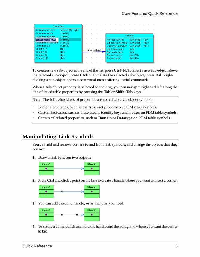
To create a new sub-object at the end of the list, press Ctrl+N. To insert a new sub-object abovethe selected sub-object, press Ctrl+I. To delete the selected sub-object, press Del. Right-clicking a sub-object opens a contextual menu offering useful commands.
When a sub-object property is selected for editing, you can navigate right and left along theline of its editable properties by pressing the Tab or Shift+Tab keys.
Note: The following kinds of properties are not editable via object symbols:
• Boolean properties, such as the Abstract property on OOM class symbols.• Custom indicators, such as those used to identify keys and indexes on PDM table symbols.• Certain calculated properties, such as Domain or Datatype on PDM table symbols.
Manipulating Link SymbolsYou can add and remove corners to and from link symbols, and change the objects that theyconnect.
1. Draw a link between two objects:
2. Press Ctrl and click a point on the line to create a handle where you want to insert a corner:
3. You can add a second handle, or as many as you need:
4. To create a corner, click and hold the handle and then drag it to where you want the cornerto be:
Core Features Quick Reference
Quick Reference 5
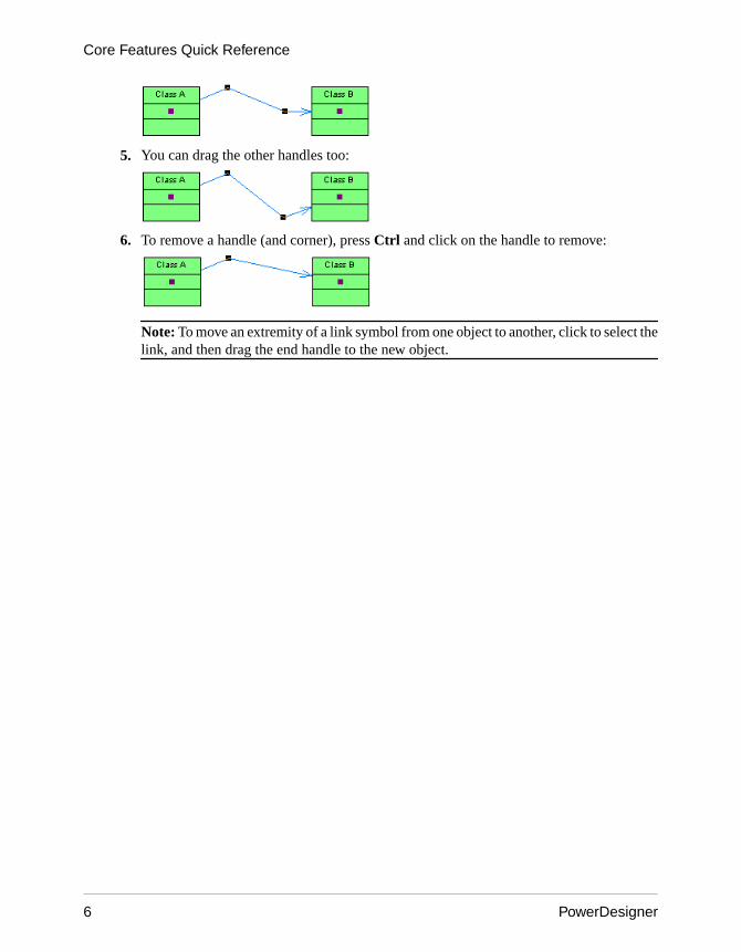
5. You can drag the other handles too:
6. To remove a handle (and corner), press Ctrl and click on the handle to remove:
Note: To move an extremity of a link symbol from one object to another, click to select thelink, and then drag the end handle to the new object.
Core Features Quick Reference
6 PowerDesigner

Glossary Quick Reference
The glossary model (GLM) helps you capture and organize the terminology to be used fornaming your model objects. An administrator deploys the glossary, and users enable it in theirmodels to provide autocompletion for object names and model checks to ensure compliance.The glossary appears in the Browser Glossary tab and updates are pushed to users each timethey connect to the repository, or on demand. Only one glossary is permitted per repository.
Administering the GlossaryAn administrator performs the initial deployment of the glossary to the repository by addingterms to it and checking it into the repository:
• To control access to the glossary, right-click the Glossary node, and select Permissions.By default, all users have Read permission on the glossary.
• To import terms from the names of objects from a PowerDesigner model open in yourworkspace, right-click the Glossary node, and select Import from Model.
• To import terms from an Excel or CSV file, right-click the Glossary node, and selectImport from Excel File.
• To create a glossary terms list, right-click the Glossary node, and select New > GlossaryTerms List.
Using the Glossary
• To consult the glossary, click the Browser Glossary tab.• To enable the use of the glossary in your model, select Tools > Model Options, then click
Naming Convention in the category list and select Use glossary for autocompletion andcompliance checking.
• To check glossary compliance, select Tools > Check Model and select the Name/Codecontains terms not in glossary and Name/Code contains synonyms of glossary termsfor the types of objects whose names you want to verify.
Glossary Quick Reference
Quick Reference 7

DocumentationFor detailed documentation, see Core Features Guide > Modeling with PowerDesigner > TheBrowser > The Glossary.
Glossary Quick Reference
8 PowerDesigner

Requirements Model Quick Reference
A requirements model (RQM) helps you analyze any kind of written requirements and linkthem with users and groups who will implement them and with design objects in other models.You can use an RQM to represent any structured document (e.g. functional specification, testplan, business goals, etc.) and import and export hierarchies of requirements as MS Worddocuments.
Creating an RQM
• To create a new RQM - Select File > New Model, and choose Requirements Model.• To create a new RQM by importing a Word document - Select File > Import > Word
Document.
The following types of views are available:
• A requirements document view displays a list of written requirements in a hierarchic grid.Multiple views can be created with different filters to display various subsets ofrequirements.
• A traceability matrix view displays the links between requirements and objects from othertypes of models, external files or other requirements.
• A user allocation matrix view displays the links between requirements and the users andgroups who will fulfill them.
Linking Requirements with Design Objects and External FilesYou can link requirements to objects from other types of models, external files, and otherrequirements on the Requirement Traceability Links tab of the requirement property sheet.
DocumentationFor detailed documentation, see Requirements Modeling.
Requirements Model Quick Reference
Quick Reference 9

Requirements Model Quick Reference
10 PowerDesigner

Enterprise Architecture Model QuickReference
An enterprise architecture model (EAM) helps you analyze and document your organizationand its business functions, along with the applications and systems that support them and thephysical architecture on which they are implemented.
Creating an EAM
• To create a new EAM - Select File > New Model, and choose Enterprise ArchitectureModel.
• To create a new EAM by importing a Visio diagram - Open your diagram in Visio andselect PowerDesigner > Export to PowerDesigner Model.
The following types of diagrams are available:
Enterprise Architecture Model Quick Reference
Quick Reference 11

• A process map provides a graphical view of your business architecture, and helps youidentify your business functions and high-level processes, independent of the people andbusiness units who fulfill them.
• An organization chart provides a graphical view of your organization as a tree structure,and helps you analyze and display the relationships between organization units (divisions,groups, teams, etc), individuals, and roles.
• A business communication diagram provides a graphical view of your organization, andhelps you analyze, the relationships, flows, and other connections between businessfunctions, organization units, roles, and sites.
• A city planning diagram provides a graphical view of the big picture of your enterprisearchitecture, using the metaphor of planning the infrastructure of a city to represent theorganization of systems, applications, etc into architectural areas.
• A service-oriented diagram provides a graphical view of your business and applicationservices and the relationships between them, and helps you associate applications andother application layer objects with business services and processes to assist with SOAdesign.
• An application architecture diagram provides a high-level graphical view of theapplication architecture, and helps you identify applications, sub-applications,components, databases, services, etc, and their interactions.
• A technology infrastructure diagram provides a high-level graphical view of the physicalarchitecture required to support the application architecture.
Exporting and Importing Objects to and from Other ModelsThe EAM provides wizards to export EA objects to lower-level models and to importimplementation objects to be represented in the EAM:
• To export EAM objects to another model - Select Tools > Export Objects Wizard• To import objects from other models into an EAM - Select Tools > Import Objects
Wizard
DocumentationFor detailed documentation, see Enterprise Architecture Modeling.
Enterprise Architecture Model Quick Reference
12 PowerDesigner
Business Process Model Quick Reference
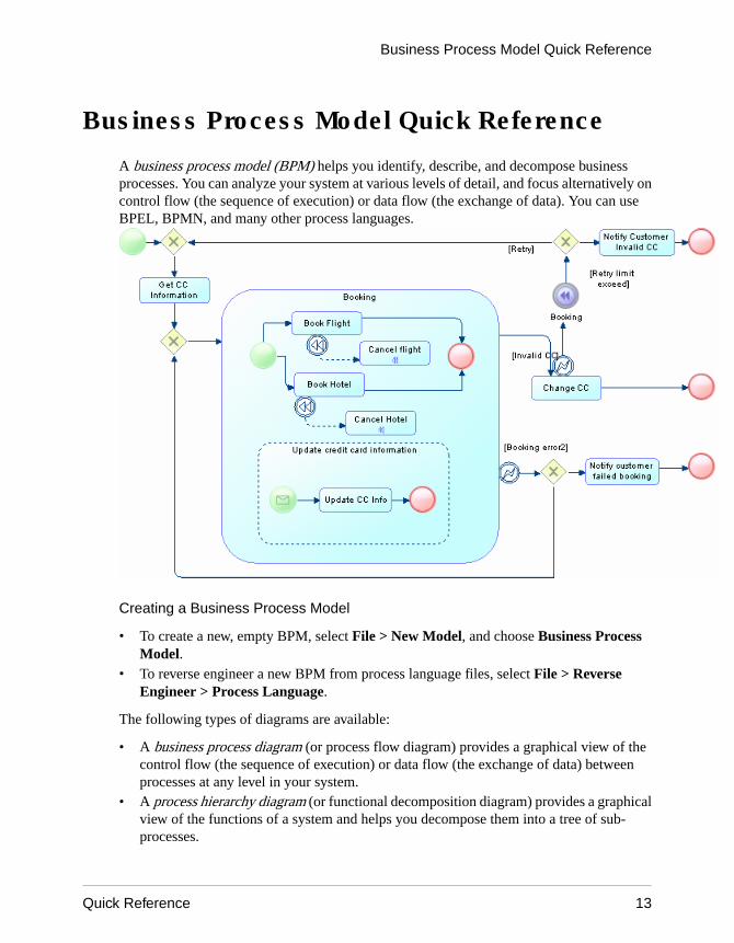
A business process model (BPM) helps you identify, describe, and decompose businessprocesses. You can analyze your system at various levels of detail, and focus alternatively oncontrol flow (the sequence of execution) or data flow (the exchange of data). You can useBPEL, BPMN, and many other process languages.
Creating a Business Process Model
• To create a new, empty BPM, select File > New Model, and choose Business ProcessModel.
• To reverse engineer a new BPM from process language files, select File > ReverseEngineer > Process Language.
The following types of diagrams are available:
• A business process diagram (or process flow diagram) provides a graphical view of thecontrol flow (the sequence of execution) or data flow (the exchange of data) betweenprocesses at any level in your system.
• A process hierarchy diagram (or functional decomposition diagram) provides a graphicalview of the functions of a system and helps you decompose them into a tree of sub-processes.
Business Process Model Quick Reference
Quick Reference 13

• A process service diagram provides a graphical view of the services, operations, andinterfaces available in your system.
Working with Data in a BPMPowerDesigner provides various methods for linking data in your BPM to data items, entities,tables or classes in other PowerDesigner models:
• To link data in a BPM with other PowerDesigner objects, use the Definition field on theGeneral tab of the data property sheet.
• To export data in a BPM to other PowerDesigner objects, select Tools > Data ExportWizard.
• To import other PowerDesigner objects as data in a BPM, select Tools > Data ImportWizard.
Working with Process Language DefinitionsThe process language definition file defines features specific to the language being modeled:
• To open the process language definition file in the Resource Editor, select Language >Edit Current Process Language.
• To change the process language to model with, select Language > Change CurrentProcess Language.
DocumentationFor detailed documentation, see Business Process Modeling.
Business Process Model Quick Reference
14 PowerDesigner
Conceptual and Logical Data Model QuickReference
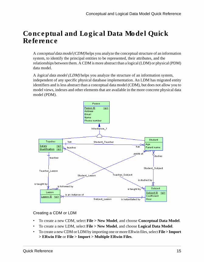
A conceptual data model (CDM) helps you analyze the conceptual structure of an informationsystem, to identify the principal entities to be represented, their attributes, and therelationships between them. A CDM is more abstract than a logical (LDM) or physical (PDM)data model.
A logical data model (LDM) helps you analyze the structure of an information system,independent of any specific physical database implementation. An LDM has migrated entityidentifiers and is less abstract than a conceptual data model (CDM), but does not allow you tomodel views, indexes and other elements that are available in the more concrete physical datamodel (PDM).
Creating a CDM or LDM
• To create a new CDM, select File > New Model, and choose Conceptual Data Model.• To create a new LDM, select File > New Model, and choose Logical Data Model.• To create a new CDM or LDM by importing one or more ERwin files, select File > Import
> ERwin File or File > Import > Multiple ERwin Files.
Conceptual and Logical Data Model Quick Reference
Quick Reference 15

Specifying a Modeling Notation and Other Options
• To specify a modeling notation and set other model options, select Tools > ModelOptions.
Generating Other ModelsYou can generate other PowerDesigner models from a CDM or LDM by selecting Tools >:
• Generate Conceptual Data Model (or press Ctrl+Shift+C)• Generate Logical Data Model (or press Ctrl+Shift+L)• Generate Physical Data Model (or press Ctrl+Shift+P)• [CDM only] Generate Object-Oriented Model (or press Ctrl+Shift+O)
DocumentationFor detailed documentation, see Data Modeling.
Conceptual and Logical Data Model Quick Reference
16 PowerDesigner

Physical Data Model Quick Reference
A physical data model (PDM) helps you to analyze the tables, views, and other objects in adatabase, including multidimensional objects necessary for data warehousing. A PDM ismore concrete than a conceptual (CDM) or logical (LDM) data model. You can model,reverse-engineer, and generate for all the most popular DBMSs.
Creating a Physical Data Model
• To create a new, empty PDM, select File > New Model, and choose Physical DataModel.
• To reverse engineer a new PDM from a live database connection, select File > ReverseEngineer > Database.
• To create a new PDM by importing one or more ERwin files, select File > Import >ERwin File or File > Import > Multiple ERwin Files.
The following types of diagrams are available:
• A physical data diagram provides a graphical view of your database structure, and helpsyou analyze its tables (including their columns, indexes, and triggers), views, andprocedures, and the references between them.
Physical Data Model Quick Reference
Quick Reference 17

• A multidimensional data diagram provides a graphical view of your datamart or datawarehouse database, and helps you identify the facts and dimensions that will be used tobuild its cubes.
Specifying a Modeling Notation and Other Options
• To specify a modeling notation, column, reference, and ownership defaults and set othermodel options, select Tools > Model Options.
Interacting with Databases
• To connect to a database, select Database > Connect.• To generate a database, select Database > Generate Database.• To modify a database, select Database > Apply Model Changes to Database.• To reverse engineer from a live database connection into an existing PDM, select
Database > Update Model from Database.• To generate test data to a database, select Database > Generate Test Data.• To estimate the size of a database, select Database > Estimate Database Size
Generating Other ModelsYou can generate other PowerDesigner models from a PDM by selecting Tools >:
• Generate Conceptual Data Model (or press Ctrl+Shift+C)• Generate Logical Data Model (or press Ctrl+Shift+L)• Generate Physical Data Model (or press Ctrl+Shift+P)• Generate Object-Oriented Model (or press Ctrl+Shift+O)• Generate XML Model (or press Ctrl+Shift+M)
Working with DBMS DefinitionsThe DBMS definition file defines features specific to the DBMS being modeled:
• To open the DBMS definition file in the Resource Editor, select Database > Edit CurrentDBMS.
• To change the DBMS to model with, select Database > Change Current DBMS.• To set default DBMS-specific physical options, select Database > Default Physical
Options.
DocumentationFor detailed documentation, see Data Modeling.
Physical Data Model Quick Reference
18 PowerDesigner

Data Movement Model Quick Reference
A data movement model (DMM) provides a global view of the movement of information inyour organization. You can analyze and document where your data originates, where it movesto, and how it is transformed on the way, including replications and ETL.
Creating a Data Movement Model
• To create a new, empty DMM - Select File > New Model, and choose Data MovementModel.
• To reverse engineer replication processes into a DMM from a consolidated databaseconnection - Select Tools > Reverse Engineering Replication Server.
The following types of diagrams are available:
• A data movement diagram provides a high-level graphical view of the movement of yourinformation, including data sources, replications, and ETL operations.
• A data transformation diagram provides a graphical view of the inputs, outputs, and stepsinvolved in a data transformation task.
• A transformation control flow diagram provides a graphical view of the order in which aseries of data transformation tasks is linked together in a control flow.
Creating Replication and Transformation Environments
• To create a replication environment, select Tools > Replication Wizard.• To create a transformation process to transform data from a PDM, select Tools >
Transformation Wizard.• To create a transformation process from existing PDM-to-PDM mappings, select Tools >
Convert Mappings to ETL Wizard.
DocumentationFor detailed documentation, see Data Movement Modeling.
Data Movement Model Quick Reference
Quick Reference 19

Data Movement Model Quick Reference
20 PowerDesigner
Object-Oriented Model Quick Reference
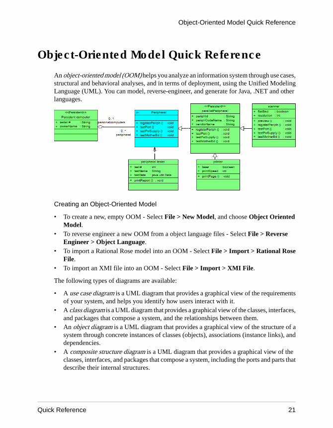
An object-oriented model (OOM) helps you analyze an information system through use cases,structural and behavioral analyses, and in terms of deployment, using the Unified ModelingLanguage (UML). You can model, reverse-engineer, and generate for Java, .NET and otherlanguages.
Creating an Object-Oriented Model
• To create a new, empty OOM - Select File > New Model, and choose Object OrientedModel.
• To reverse engineer a new OOM from a object language files - Select File > ReverseEngineer > Object Language.
• To import a Rational Rose model into an OOM - Select File > Import > Rational RoseFile.
• To import an XMI file into an OOM - Select File > Import > XMI File.
The following types of diagrams are available:
• A use case diagram is a UML diagram that provides a graphical view of the requirementsof your system, and helps you identify how users interact with it.
• A class diagram is a UML diagram that provides a graphical view of the classes, interfaces,and packages that compose a system, and the relationships between them.
• An object diagram is a UML diagram that provides a graphical view of the structure of asystem through concrete instances of classes (objects), associations (instance links), anddependencies.
• A composite structure diagram is a UML diagram that provides a graphical view of theclasses, interfaces, and packages that compose a system, including the ports and parts thatdescribe their internal structures.
Object-Oriented Model Quick Reference
Quick Reference 21

• A package diagram is a UML diagram that provides a high-level graphical view of theorganization of your application, and helps you identify generalization and dependencylinks between the packages.
• A sequence diagram is a UML diagram that provides a graphical view of the chronology ofthe exchange of messages between objects and actors for a use case, the execution of anoperation, or an interaction between classes, with an emphasis on their chronology.
• A communication diagram is a UML diagram that provides a graphical view of theinteractions between objects for a use case scenario, the execution of an operation, or aninteraction between classes, with an emphasis on the system structure.
• An interaction diagram is a UML diagram that provides a high-level graphical view of thecontrol flow of your system as it is decomposed into sequence and other interactiondiagrams.
• An activity diagram is a UML diagram that provides a graphical view of a system behavior,and helps you functionally decompose it in order to analyze how it will be implemented.
• A statechart diagram is a UML diagram that provides a graphical view of a State Machine,the public behavior of a classifier (component or class), in the form of the changes overtime of the state of the classifier and of the events that permit the transition from one state toanother.
• A component diagram is a UML diagram that provides a graphical view of thedependencies and generalizations among software components, including source codecomponents, binary code components, and executable components.
• A deployment diagram is a UML diagram that provides a graphical view of the physicalconfiguration of run-time elements of your system.
Generating Other ModelsYou can generate other PowerDesigner models from an OOM by selecting Tools >:
• Generate Conceptual Data Model (or press Ctrl+Shift+C)• Generate Physical Data Model (or press Ctrl+Shift+P)• Generate Object-Oriented Model (or press Ctrl+Shift+O)• Generate XML Model (or press Ctrl+Shift+M)
Working with Object Language DefinitionsThe object language definition file defines features specific to the language being modeled:
• To open the object language definition file in the Resource Editor, select Language > EditCurrent Object Language.
• To change the process language to model with, select Language > Change CurrentObject Language.
DocumentationFor detailed documentation, see Object-Oriented Modeling.
Object-Oriented Model Quick Reference
22 PowerDesigner
XML Model Quick Reference
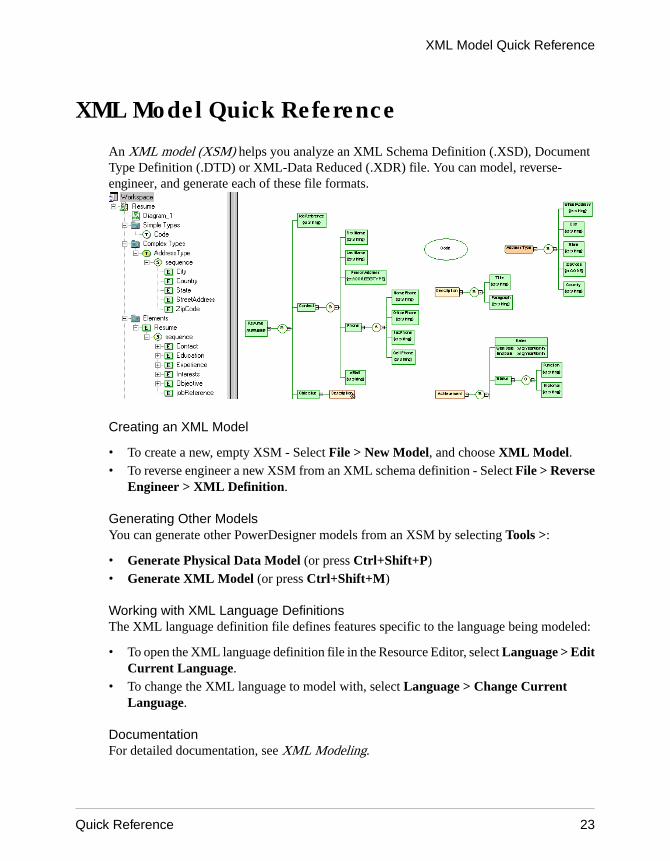
An XML model (XSM) helps you analyze an XML Schema Definition (.XSD), DocumentType Definition (.DTD) or XML-Data Reduced (.XDR) file. You can model, reverse-engineer, and generate each of these file formats.
Creating an XML Model
• To create a new, empty XSM - Select File > New Model, and choose XML Model.• To reverse engineer a new XSM from an XML schema definition - Select File > Reverse
Engineer > XML Definition.
Generating Other ModelsYou can generate other PowerDesigner models from an XSM by selecting Tools >:
• Generate Physical Data Model (or press Ctrl+Shift+P)• Generate XML Model (or press Ctrl+Shift+M)
Working with XML Language DefinitionsThe XML language definition file defines features specific to the language being modeled:
• To open the XML language definition file in the Resource Editor, select Language > EditCurrent Language.
• To change the XML language to model with, select Language > Change CurrentLanguage.
DocumentationFor detailed documentation, see XML Modeling.
XML Model Quick Reference
Quick Reference 23

XML Model Quick Reference
24 PowerDesigner

Free Model Quick Reference
A free model (FEM) provides a context-free environment for modeling any kind of objects orsystems. It is generally associated with a set of extensions, which allow you to define your ownconcepts and graphical symbols.
Creating a Free Model
• To create a new, empty FEM - Select File > New Model, and choose Free Model.
Changing a Symbol ImagePowerDesigner provides a library of high-quality symbols to use in your models. To changethe image associated with a symbol, right-click the symbol and select Change Image.
DocumentationSee the Extensions Quick Reference on page 27. For detailed documentation, seeCustomizing and Extending PowerDesigner > Extension Files.
Free Model Quick Reference
Quick Reference 25

Free Model Quick Reference
26 PowerDesigner

Extensions Quick Reference
Extensions files (*.xem) allow you to customize and extend the PowerDesigner metamodelto support your exact modeling needs. You can define additional properties for existingobjects or specify entirely new types of objects, modify the PowerDesigner interface(reorganizing and adding property sheet tabs, Toolbox tools and menu items), and defineadditional generation targets and options.
Creating Extensions from a Property Sheet
• To create an extended attribute directly from an object property sheet, click the menubutton, and select New Attribute.
• To create a new collection directly from an object property sheet, click the menu button,and select New List of Associated Objects.
Working with Extension Files
• To attach an existing extension file to a model, select Model > Extensions, and click theImport tool.
Extensions Quick Reference
Quick Reference 27

• To create a new extension file, select Model > Extensions, click the Add a Row tool, entera name for the file, and then click the Properties tool.
Types of ExtensionYou can extend the metamodel in the following ways:
• Create or sub-classify new kinds of objects:• Metaclasses – drawn from the metamodel as a basis for extension.• Stereotypes [for metaclasses and stereotypes only] – sub-classify metaclasses by
stereotype.• Criteria – sub-classify metaclasses by evaluating conditions.
• Add new properties and collections to objects and display them:• Extended attributes – to add metadata.• Extended collections and compositions – to enable manual linking between objects.• Calculated collections – to automate linking between objects.• Dependency matrices – to show dependencies between two types of objects.• Forms – to modify property sheets and add custom dialogs.• Custom symbols – to change the appearance of objects in diagrams.
• Add constraints and validation rules to objects:• Custom checks – to test the validity of your models on demand• Event handlers – to perform validation or invoke methods automatically.
• Execute commands on objects:• Methods – VBScripts to be invoked by menus or form buttons.• Menus [for metaclasses and stereotypes only] – to add commands to PowerDesigner
menus.• Generate objects in new ways:
• Templates – to extract text from object properties.• Generated Files - to assemble templates for preview and generation of files• Transformations – to automate changes to objects at generation or on demand.
• Map correspondences between different metamodels:• Object generations - to define mappings between different modules in the
PowerDesigner metamodel for model-to-model generation.• XML imports - to define mappings between an XML schema and a PowerDesigner
module to import XML files as models.
DocumentationFor detailed documentation, see Customizing and Extending PowerDesigner > ExtensionFiles.
Extensions Quick Reference
28 PowerDesigner
Shortcut Keys
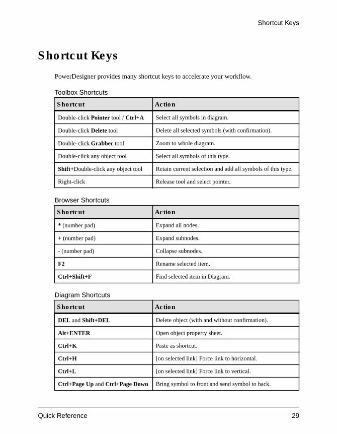
PowerDesigner provides many shortcut keys to accelerate your workflow.
Toolbox Shortcuts
Shortcut Action
Double-click Pointer tool / Ctrl+A Select all symbols in diagram.
Double-click Delete tool Delete all selected symbols (with confirmation).
Double-click Grabber tool Zoom to whole diagram.
Double-click any object tool Select all symbols of this type.
Shift+Double-click any object tool Retain current selection and add all symbols of this type.
Right-click Release tool and select pointer.
Browser Shortcuts
Shortcut Action
* (number pad) Expand all nodes.
+ (number pad) Expand subnodes.
- (number pad) Collapse subnodes.
F2 Rename selected item.
Ctrl+Shift+F Find selected item in Diagram.
Diagram Shortcuts
Shortcut Action
DEL and Shift+DEL Delete object (with and without confirmation).
Alt+ENTER Open object property sheet.
Ctrl+K Paste as shortcut.
Ctrl+H [on selected link] Force link to horizontal.
Ctrl+L [on selected link] Force link to vertical.
Ctrl+Page Up and Ctrl+Page Down Bring symbol to front and send symbol to back.
Shortcut Keys
Quick Reference 29
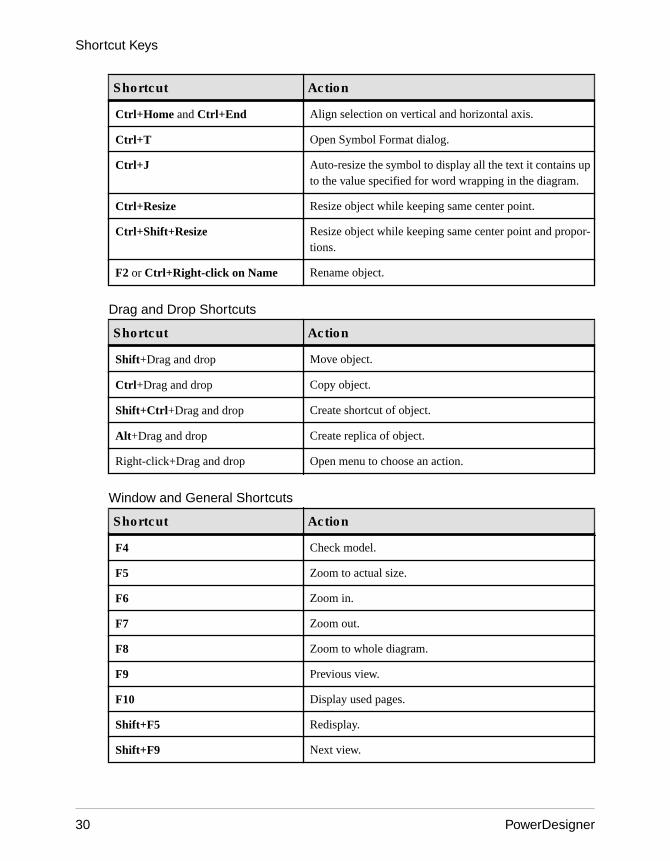
Shortcut Action
Ctrl+Home and Ctrl+End Align selection on vertical and horizontal axis.
Ctrl+T Open Symbol Format dialog.
Ctrl+J Auto-resize the symbol to display all the text it contains upto the value specified for word wrapping in the diagram.
Ctrl+Resize Resize object while keeping same center point.
Ctrl+Shift+Resize Resize object while keeping same center point and propor-tions.
F2 or Ctrl+Right-click on Name Rename object.
Drag and Drop Shortcuts
Shortcut Action
Shift+Drag and drop Move object.
Ctrl+Drag and drop Copy object.
Shift+Ctrl+Drag and drop Create shortcut of object.
Alt+Drag and drop Create replica of object.
Right-click+Drag and drop Open menu to choose an action.
Window and General Shortcuts
Shortcut Action
F4 Check model.
F5 Zoom to actual size.
F6 Zoom in.
F7 Zoom out.
F8 Zoom to whole diagram.
F9 Previous view.
F10 Display used pages.
Shift+F5 Redisplay.
Shift+F9 Next view.
Shortcut Keys
30 PowerDesigner
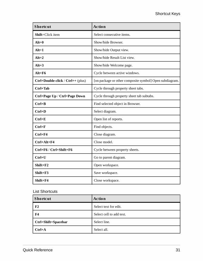
Shortcut Action
Shift+Click item Select consecutive items.
Alt+0 Show/hide Browser.
Alt+1 Show/hide Output view.
Alt+2 Show/hide Result List view.
Alt+3 Show/hide Welcome page.
Alt+F6 Cycle between active windows.
Ctrl+Double-click / Ctrl++ (plus) [on package or other composite symbol] Open subdiagram.
Ctrl+Tab Cycle through property sheet tabs.
Ctrl+Page Up / Ctrl+Page Down Cycle through property sheet tab subtabs.
Ctrl+B Find selected object in Browser.
Ctrl+D Select diagram.
Ctrl+E Open list of reports.
Ctrl+F Find objects.
Ctrl+F4 Close diagram.
Ctrl+Alt+F4 Close model.
Ctrl+F6 / Ctrl+Shift+F6 Cycle between property sheets.
Ctrl+U Go to parent diagram.
Shift+F2 Open workspace.
Shift+F3 Save workspace.
Shift+F4 Close workspace.
List Shortcuts
Shortcut Action
F2 Select text for edit.
F4 Select cell to add text.
Ctrl+Shift+Spacebar Select line.
Ctrl+A Select all.
Shortcut Keys
Quick Reference 31

Shortcut Action
Ctrl+Shift+A Deselect all.
Ctrl+N Add entry.
Ctrl+I Insert entry.
Ctrl+D Delete entry.
Code Preview Tab Shortcuts
Shortcut Action
F2 Next bookmark.
F3 Find next.
Shift+F11 Menu.
Ctrl+F2 Insert/Remove bookmark.
Ctrl+I Insert file.
Shortcut Keys
32 PowerDesigner

IndexB
bend link 5business process model (BPM) 13
C
conceptual data model (CDM) 15core features 1
D
data movement model (DMM) 19
E
editsymbol 3
enterprise architecture model (EAM) 11extensions 27
F
free model (FEM) 25
G
glossary 7
L
linkbend 5change symbol 5
linking and syncing 1, 7logical data model (LDM) 15
O
object-oriented model (OOM) 21
P
physical data model (PDM) 17
R
requirements model (RQM) 9resize
symbol 3resource editor 27
S
selectall symbols 3connected symbols 3symbol 3
shortcut keys 29symbol
edit 3resize 3select 3
X
XML model (XSM) 23
Index
Quick Reference 33

Index
34 PowerDesigner