corner detector based on global and local curvature properties
TRANSCRIPT

Cc
XUDPE
NUD
P
1
Ciatiai
sficslticHvndtppccpolpcc
0
Optical Engineering 47�5�, 057008 �May 2008�
O
orner detector based on global and localurvature properties
iao Chen Heniversity of Hong Kongepartment of Computer Scienceokfulam Road, Hong Kong-mail: [email protected]
elson H. C. Yungniversity of Hong Kongepartment of Electrical and
Electronic Engineeringokfulam Road, Hong Kong
Abstract. This paper proposes a curvature-based corner detector thatdetects both fine and coarse features accurately at low computationalcost. First, it extracts contours from a Canny edge map. Second, it com-putes the absolute value of curvature of each point on a contour at a lowscale and regards local maxima of absolute curvature as initial cornercandidates. Third, it uses an adaptive curvature threshold to removeround corners from the initial list. Finally, false corners due to quantiza-tion noise and trivial details are eliminated by evaluating the angles ofcorner candidates in a dynamic region of support. The proposed detectorwas compared with popular corner detectors on planar curves and gray-level images, respectively, in a subjective manner as well as with a fea-ture correspondence test. Results reveal that the proposed detector per-forms extremely well in both fields. © 2008 Society of Photo-OpticalInstrumentation Engineers. �DOI: 10.1117/1.2931681�
Subject terms: corner detection; adaptive threshold; region of support; curvature;contour; round corner; obtuse corner.
Paper 070884R received Oct. 30, 2007; revised manuscript received Mar. 10,2008; accepted for publication Mar. 13, 2008; published online May 22, 2008.
Introduction
orners in images represent critical information in describ-ng object features that are essential for pattern recognitionnd identification. There are many applications that rely onhe successful detection of corners, including motion track-ng, object recognition, and stereo matching.1–3 As a result,number of corner detection methods have been proposed
n the past.Kitchen and Rosenfeld4 proposed a corner detection
cheme based on a differential operator that determines therst and second partial derivatives of an image, from whichorners are identified as local extrema. This method is sen-itive to noise, and suffers from missing junctions and poorocalization. Moravec5 observed that the difference be-ween adjacent pixels of an edge or a uniform part of themage is small and at the corner the difference is signifi-antly high in all directions. The idea was later used byarris6 to develop the Plessey algorithm. This method pro-ides good repeatability under rotation and various illumi-ations, and is often used for stereo matching and imageatabase retrieval. Unfortunately, it is sensitive to quantiza-ion noise and suffers from a loss in localization accuracy,articularly at certain junction types. Smith and Brady7 pro-osed a detector named SUSAN using a circular mask fororner and edge detection. Although SUSAN’s corner lo-alization and noise robustness are better than those of thereviously mentioned algorithms, it is time-consuming inbtaining an area �called the USAN� and finding corners inarge windows. Another formulation of USAN was pro-osed in Ref. 8, in which two oriented cross operators,alled crosses as oriented pair �COP�, were used instead ofircular mask as in Ref. 7.
091-3286/2008/$25.00 © 2008 SPIE
ptical Engineering 057008-
Other corner detectors are described in Ref. 9–23 . Insummary, most of them are single-scale detectors and workwell if the image has similar-size features, but are ineffec-tive otherwise. As a result, either the fine or the coarsefeatures are poorly segmented, which is unacceptable be-cause natural images normally contain both kinds of fea-tures.
To alleviate this problem, Rattarangsi and Chin24 pro-posed a multiscale algorithm based on curvature scalespace �CSS�, which can detect corners of planar curves.Although it can detect multiple-size features, the algorithmis computationally intensive due to parsing features are theentire scale space. Moreover, it detects false corners oncircles. Some other multiscale approaches do not check allthe scales, e.g., the technique for smoothing a curve adap-tively based on its roughness in the region, as proposed inRef. 25. Given that the CSS technique is suitable for recov-ering invariant geometric features of a planar curve at mul-tiple scales,26 Mokhtarian et al. proposed two CSS cornerdetectors27,28 for gray-level images. These CSS detectorsperform well in corner detection and are robust to noise,but they have problems too.
To begin with, we quote the definition of curvature, K,from Ref. 26 as follows:
K�u,�� =X�u,��Y�u,�� − X�u,��Y�u,��
�X�u,��2 + Y�u,��2�1.5, �1�
where X�u ,��=x�u� � g�u ,��, X�u ,��=x�u� � g�u ,��,Y�u ,��=y�u� � g�u ,��, Y�u ,��=y�u� � g�u ,��, and � isthe convolution operator, while g�u ,�� denotes a Gaussianof width �, and g�u ,��, g�u ,�� are the first and secondderivatives of g�u ,��, respectively. The following steps are
May 2008/Vol. 47�5�1

ui
anonitpmonRhphptfattcnt
pwttStsnlrdibi
He and Yung: Corner detector based on global and local curvature properties
O
sed by the original CSS algorithm27to detect corners of anmage:
1. Apply Canny edge detection to the gray-level image,and obtain a binary edge map.
2. Extract edge contours from the edge map. When theedge reaches an end point, fill the gap and continuethe extraction if the end point is nearly connected toanother end point, or mark this point as a T-junctioncorner if the end point is nearly connected to an edgecontour, but not to another end point.
3. From each contour, compute curvature values at ahigh scale, �high. Then consider the local maxima asinitial corners whose absolute curvatures are abovethe threshold t and twice as high as one of the neigh-boring local minima; t in this case is selected manu-ally.
4. Track the corners from the highest scale to the lowestscale to improve the localization error.
5. Compare the T-junction corners with other corners,and remove one of any two corners that are close toeach other.
There are a number of problems associated with thislgorithm. Firstly, a single scale is used in determining theumber of corners �step 3�, and multiple scales are usednly for localization. Not surprisingly, it misses true cor-ers when �high is large and detects false corners when �highs small. If the algorithm is applied to a complex image,his effect becomes more prominent, and choosing an ap-ropriate �high becomes challenging. Secondly, as localaxima of the absolute curvature function make up the set
f corner candidates, a corner candidate can be a true cor-er, a rounded corner, or noise. Mokhtarian and Suomela inef. 27 asserted that the curvature of a true corner has aigher value than that of a round corner or noise, but inractice it is very easy to find a corner due to noise that hasigher curvature value than an obtuse corner. Thirdly, theerformance of the algorithm depends on the selection ofhreshold value t, the proper value of which may changerom image to image, or even from one edge contour tonother. Lastly, tracking is performed to improve localiza-ion by computing curvature at a lower scale and examininghe corner candidates in a small neighborhood of previousorners. When multiple corner candidates exist in the smalleighborhood, the corners may be mismatched. This situa-ion is likely to result in a poor localization performance.
The enhanced CSS algorithm28 dealt with some of theseroblems, by using different scales of the CSS for contoursith different lengths, and smoothing the curvature func-
ion for long contours to remove false maxima. However,he criterion for selecting contour lengths is not explicit.uch a criterion is obviously important, for it determines
he success of the algorithm. On the other hand, it is rea-onable to believe that the meaningful scale value does notecessarily depend on the contour length. The contourength is not a major attribute of a curve, since the algo-ithm for edge contour extraction can alter it. In fact,ifferent-size features, which need different scales, can ex-st on the same contour. Although the enhanced CSS offersetter results than the original CSS, there is much room formprovement.
ptical Engineering 057008-
Our survey revealed that corner detection involves ex-tracting corners in gray-level images and also in digitalcurves, which can be extended to gray-level images byedge detection and contour extraction. The former approachregards a corner as an individual feature, and detects cor-ners only according to their local properties �curvature, gra-dient magnitude, etc.�, while the latter approach has thepotential to detect corners according to their global proper-ties by considering the relationship between neighboringfeatures in the contours. Another observation is that con-ventional corner detectors are not able to distinguish roundcorners from obtuse corners. Broadly, a round corner is apoint on an arc, which has the highest curvature among thepoints on the arc, but the curvature differences betweenthese points are small. On the other hand, an obtuse corner,whose absolute curvature may be similar to that of a roundcorner, always has a prominent point whose curvature issignificantly larger than the curvature of its neighboringpoints. Obtuse corners are much more valuable and usefulfor representing the shape of objects than round corners,but they often are not appropriately distinguished by exist-ing corner detectors. Furthermore, there is no explicit cri-terion to distinguish round corner and obtuse corner.
To summarize, the goals of this paper are: �1� to con-sider corners to be defined by global and local curvatureproperties, �2� to distinguish round corners from obtuse cor-ners, and �3� to parameterize the approach.
This paper proposes a new and improved corner detec-tion method, of which a preliminary version has been de-scribed in Ref. 29. It relies on an edge map from whichabsolute curvature is computed at a relatively low scale toretain almost all corners, true or false. All the local maximaof the absolute curvature function are regarded as cornercandidates. We assume that true corners are completely in-cluded in this set of corner candidates, together with somefalse corners. This assumption is only true when the edgemap is extracted using a low threshold and the scale used islow enough. In fact, both conditions are easy to achieve.
Since a local maximum may represent a true corner, around corner, or simply noise,27 two criteria are adopted toremove the latter two from the initial list of corner candi-dates To do that, we first compare the corner candidatesusing an adaptive local threshold �automatically calculated�instead of a single global threshold to remove the roundcorners. Second, the angles of the remaining corner candi-dates are evaluated to eliminate any false corners due toquantization noise and trivial details. The evaluation isbased on a dynamic region of support, which varies fromcorner to corner according to adjacent corner candidates.We also introduce an end-point handling method to ensurethat end points are appropriately dealt with.
The proposed detector has been tested and evaluatedover a number of images with multiple-size features andcompared with popular corner detectors on planar curves aswell as on gray-level images. It is found that the proposedmethod outperforms the rest and is more consistent fromimage to image.
In Sec. 2, our proposed corner detection method is pre-sented in detail. Section 3 depicts and discusses the experi-ment results. The conclusions are presented in Sec. 4.
May 2008/Vol. 47�5�2
2
2Ttmlleot
2L
A
woiae
A
wpp
decss
A
wbpe
He and Yung: Corner detector based on global and local curvature properties
O
Proposed Method
.1 Overviewraditional single-scale algorithms �e.g., Refs. 4 and 7� de-
ect corners by considering their local properties, and eitheriss fine features or detect noise as false corners. The phi-
osophy of the proposed method is to utilize global andocal curvature properties, and balance their influence whenxtracting corners. With this philosophy and the problemsf traditional corner detectors in mind, a new corner detec-or is proposed as follows:
1. Detect edges using the likes of a Canny edge detectorto obtain a binary edge map.
2. Extract contours as in the CSS method.3. After contour extraction, compute the curvature at a
fixed low scale for each contour to retain the truecorners, and regard the local maxima of absolute cur-vature as corner candidates.
4. Compute a threshold adaptively according to themean curvature within a region of support. Roundcorners are removed by comparing the curvature ofcorner candidates with the adaptive threshold.
5. Based on a dynamically recalculated region of sup-port, evaluate the angles of the remaining corner can-didates to eliminate any false corners.
6. Finally, consider the end points of open contours, andmark them as corners unless they are very close toanother corner. Open and closed contours are definedby Eq. �3�.
.2 Initial List of Corner Candidateset us first define the j’th extracted contour as
j = �P1j ,P2
j , . . . ,PNj � , �2�
here Pij = �xi
j ,yij� are pixels on the contour, N is the number
f pixels on the contour, and xij, yi
j are the coordinates of the’th pixel on the j’th contour. We further define the contours closed if the distance between its end points is smallnough, and otherwise open:
j is �closed if �P1j PN
j � � T ,
open if �P1j PN
j � � T ,�3�
here the threshold T is used to determine whether two endoints are close enough. A typical value of T is 2 or 3ixels.
For a closed contour, circular convolution can be appliedirectly to smooth the contour. For an open contour, how-ver, a certain number of points should be symmetricallyompensated at both ends of the contour when it ismoothed. The contour convolved with the Gaussianmoothing kernel g is denoted by
smoothj = Aj
� g , �4�
here g is a digital Gaussian function with width controlledy �. A value �=3 has been used in all the experimentsresented in this paper. After that, the curvature value ofach pixel of the contour is computed using
ptical Engineering 057008-
Kij =
�xij�2yi
j − �2xij�yi
j
���xij�2 + ��yi
j�2�1.5 for i = 1,2, . . . ,N , �5�
where �xij = �xi+1
j −xi−1j � /2, �yi
j = �yi+1j −yi−1
j � /2, �2xij
= ��xi+1j −�xi−1
j � /2, and �2yij = ��yi+1
j −�yi−1j � /2. From Eq.
�5�, all the local maxima of the curvature function are in-cluded in the initial list of corner candidates.
2.3 Corner Evaluation
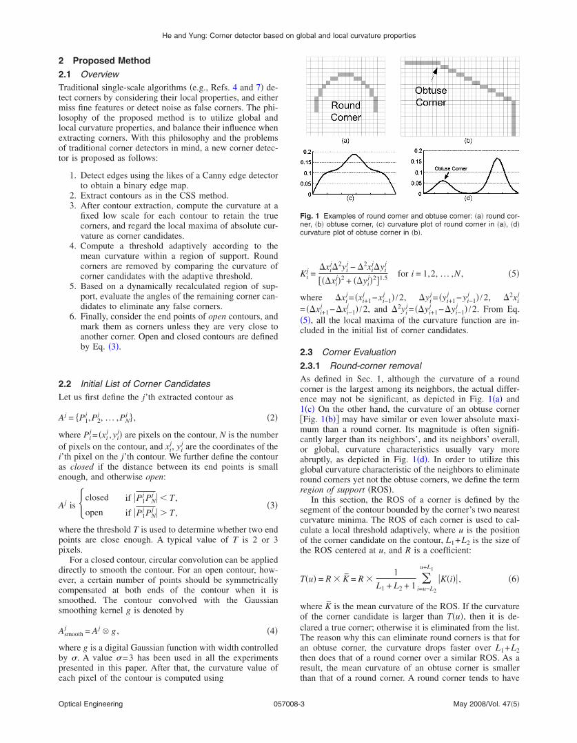
2.3.1 Round-corner removalAs defined in Sec. 1, although the curvature of a roundcorner is the largest among its neighbors, the actual differ-ence may not be significant, as depicted in Fig. 1�a� and1�c� On the other hand, the curvature of an obtuse corner�Fig. 1�b�� may have similar or even lower absolute maxi-mum than a round corner. Its magnitude is often signifi-cantly larger than its neighbors’, and its neighbors’ overall,or global, curvature characteristics usually vary moreabruptly, as depicted in Fig. 1�d�. In order to utilize thisglobal curvature characteristic of the neighbors to eliminateround corners yet not the obtuse corners, we define the termregion of support �ROS�.
In this section, the ROS of a corner is defined by thesegment of the contour bounded by the corner’s two nearestcurvature minima. The ROS of each corner is used to cal-culate a local threshold adaptively, where u is the positionof the corner candidate on the contour, L1+L2 is the size ofthe ROS centered at u, and R is a coefficient:
T�u� = R � K = R �1
L1 + L2 + 1 i=u−L2
u+L1
�K�i�� , �6�
where K is the mean curvature of the ROS. If the curvatureof the corner candidate is larger than T�u�, then it is de-clared a true corner; otherwise it is eliminated from the list.The reason why this can eliminate round corners is that foran obtuse corner, the curvature drops faster over L1+L2then does that of a round corner over a similar ROS. As aresult, the mean curvature of an obtuse corner is smallerthan that of a round corner. A round corner tends to have
Fig. 1 Examples of round corner and obtuse corner: �a� round cor-ner, �b� obtuse corner, �c� curvature plot of round corner in �a�, �d�curvature plot of obtuse corner in �b�.
May 2008/Vol. 47�5�3

anio
aerepotfcwt
wwcc
K
at
�
w=
ic
K
Imraa
2GradscbtFrcc
He and Yung: Corner detector based on global and local curvature properties
O
bsolute curvature smaller than T�u�, while an obtuse cor-er tends to have absolute curvature larger than T�u�, evenf their absolute curvatures are similar. Obviously, the truthf this depends on how R is selected.
In theory, by controlling R appropriately we should beble to differentiate round corners from obtuse corners andliminate various kinds of round corners as well. However,ound corners are ill defined by nature, and there is noxplicit criterion to distinguish them. For instance, everyoint on a circle has the same curvature, and a circle has nobvious corner. However, for an ellipse, it could be arguedhat the vertices may be considered as true corners. There-ore, whether a round corner should be regarded as a trueorner is determined by how round or sharp it is. So, it isorthwhile investigating the relationship between the na-
ion of round corner and the coefficient R.Suppose an ellipse is given by f�x�= �b2− �bx /a�2�1/2,
ith x� �−a ,a� and b�a. The vertex �0,b� of the ellipseill be a curvature maximum and therefore a likely true
orner. The absolute curvature of every ellipse point can bealculated as
�x� = f��x��1 + f��x�2�3/2 =
ba4
��bx�2 − �ax�2 + a4�3/2 ,
nd we have Kmax=K�0�=b /a2, Kmin=K�a�=a /b2. Becausehe area under the curvature function is given by
K�x� dx =� ba4
��bx�2 − �ax�2 + a4�3/2 dx
=bx
��b2 − a2�x2 + a4�1/2 ,
e have the mean curvature given by K=�−aa ��x� dx /2a
�1− �−1�� /2a=1 /a=Kmax·a /b, and the adaptive threshold
s given by T=R� K=R ·Kmax·a /b From this equation, itan be deduced that
max��T if b/a � R ,
�T if b/a � R .�7�
n other words, for the vertex of an ellipse, if the ratio of itsajor axis to its minor axis is lower than R, it is to be
egarded as a round corner. Given this relationship, we areble to use R to define the round corners to be eliminated,nd filter them out from the initial list of corner candidates.
.3.2 False-corner removalenerally speaking, a well-defined corner should have a
elatively sharp angle. As argued in Ref. 11, if we knew thengle of each corner on a contour, it would be easier toifferentiate true corners from false corners. The key to theuccess of this approach is to correctly define the angle of aorner In particular, the angle of a corner can be an am-iguous quantity that varies according to its definition andhe extent over which the angle is defined. For instance,ig. 2 depicts five points labeled on a curve, all of whichepresent local curvature maxima and can be regarded asorners. Taking point 3 as an example, if the angle of aorner is defined as an acute angle, point 3 will fall within
ptical Engineering 057008-
this definition. Moreover, if we consider point 3 within therange of points 2 and 4, then it will be classified as a truecorner too. However, if we consider point 3 within therange of points 1 and 5, then points 2, 3, and 4 may all beclassified as false corners, the reason being that points 1and 5 form almost a straight line, which indirectly impliespoints 2, 3, and 4 are the result of some local variations onthe curve. When the global curvature characteristic of acontour is not known a priori, it can be challenging todecide on the range over which a potential corner candidateshould be considered. This motivates us to propose amethod for determining an appropriate range when evalu-ating potential corner candidates based on our previouslydefined ROS.
In Sec. 2.3.1, we defined the ROS as the segment of thecontour bounded by the corner’s two nearest curvatureminima. In this section, we extend this definition to includethe two neighboring corners of the corner in question. Us-ing the same illustration in Fig. 2, if all five points labeledare corner candidates after round-corner removal, thenpoint 3 will have a new ROS spanning from points 2 to 4and will be classified as corner, because its angle is acute.On the other hand, points 2 and 4 might potentially beremoved after round-corner removal, and as a result, thenew ROS for point 3 would span from point 1 to 5. In thiscase, point 3 would likely be classified as a false corner,because its angle would be obtuse. Furthermore, some cor-ners do not have two neighboring corners, such as the cor-ner nearest to an end point of an open contour �points 1 and5�. End points of an open contour are used as additionalcorners to define the ROS.
After determining the ROS of corner candidates, theangle of a corner candidate can be defined as that betweenthe lines joining the corner point concerned and the twocenters of mass on both sides of the ROS,29 where thecenter of mass is defined as the mean position of all thepixels on one arm of the ROS. This definition enables theremoval of point 3 on a straight line as depicted in Fig. 2.However, it fails when dealing with local variations alongan arc, as depicted in Fig. 3, which is illustrated in thefollowing. After round-corner removal, points C as de-picted in Fig. 3 would most likely be considered as poten-tial true corners. The ROS of point C is then defined overpoints E and F according to our definition, where points Eand F could be corner candidates or end points. Based onthe definition of angle in Ref. 29 �Fig. 3�a��, �C may notbe obtuse enough to be considered for removal. It does nothelp if the arc extends longer �larger ROS�, for �C wouldthen become sharper.
To alleviate this problem, we redefine the angle of acorner using tangents instead. For any point in the arc, thetangent directions on its two sides form an angle at thatpoint. Similarly, a straight line can be regarded as an arcwith infinite radius of curvature, so the tangent direction of
Fig. 2 Illustration of an ambiguous case.
May 2008/Vol. 47�5�4

atttdmtspuei
ptatdp=
x
y
Srclwl
wRc
�
F
He and Yung: Corner detector based on global and local curvature properties
O
ny point on the line is the same as the line direction. Inhis respect, straight lines and arcs can be treated in exactlyhe same way. To calculate the tangent, a circle is best-fittedo the pixels on each arm of the ROS of the corner candi-ate, as shown in Fig. 3�b�. The traditional way is to mini-ize the mean squared Euclidean distance from the circle
o the pixel points. Unfortunately, there is no closed-formolution for that.30 All known algorithms involve either ap-roximation or costly iteration.31 Because optimal fitting isnnecessary in this case, a simple three-point method ismployed to determine the circle. This three-point methods detailed below, with reference to Fig. 3�b�.
First, on one arm of an ROS �from C to E, say�, threeoints �C, the mid point M, and E� are selected. If thesehree points are collinear, the tangent direction of this ROSrm is defined from C to E else the center of a supposi-ional circle C0 is deduced as follows, which has the sameistance �radius of curvature of this ROS� to the threeoints. Let C= �x1 ,y1�, M = �x2 ,y2�, E= �x3 ,y3�, and C0
�x0 ,y0�; we have
0 =�x1
2 + y12��y2 − y3� + �x2
2 + y22��y3 − y1� + �x3
2 + y32��y1 − y2�
2 · ��x1�y2 − y3� + x2�y3 − y1� + x3�y1 − y2��,
0 =�x1
2 + y12��x2 − x3� + �x2
2 + y22��x3 − x1� + �x3
2 + y32��x1 − x2�
2 · ��y1�x2 − x3� + y2�x3 − x1� + y3�x1 − x2��.
�8�
econd, a line is drawn from C to C0, and � is used toepresent the direction from C to C0, which could be cal-ulated by a four-quadrant inverse-tangent function. Simi-arly, we use � to denote the direction from C to M. Thene can have the tangent of C at this side of ROS as fol-
ows:
1 = � + sign�sin�� − ��� ·
2, �9�
here sign is a signum function. Third, the tangent of theOS from C to F is determined similarly, and is denoted by2. Fourth, the two tangent lines form the angle of theorner:
C = ��1 − 2� if �1 − 2� � ,
2 − �1 − 2� otherwise.�10�
inally, the corner checking criterion is given as follows:
Fig. 3 Angle definitions of a corner: �a� c
ptical Engineering 057008-
Ci is true corner if � Ci � �obtuse,�11�
Ci is false corner if � Ci � �obtuse.
The parameter �obtuse designates the maximum obtuse anglethat a corner can have and still be considered as a truecorner.
False corners are marked and removed after all cornercandidates have been checked. Because the set of cornercandidates will change after this step, further iterations areperformed until there are no further possible changes of thecorner list. The number of iterations is typically two orthree. Using this criterion, isolated corner candidates due toquantization noise and trivial details can be eliminated, butthe dominant corners are retained.
2.3.3 Advantage of considering global properties
Traditional single-scale methods detect corners only ac-cording to their local properties. They are ineffective forobjects with multiple-size features. We find that the globalproperty of curvature can be used to determine a more ap-propriate ROS for accurate detection. For example, theround corner in Fig. 1�a� and the contour vertex in Fig. 4�a�have similar local curvature. Taking a global view, theformer is more an arc than a corner, while the latter can beregarded as a true corner. The absolute curvature values ofthe maxima of these two contours are also similar, but thelatter has a larger region of support, and therefore a lowermean curvature. So the contour vertex in Fig. 4�a� has thetendency to be detected as a true corner by using the pro-posed method. Furthermore, by using the angle definitionover a dynamic ROS as described in Sec. 2.3.2, the latterwill be evaluated as a sharper angle and more likely beregarded as true corner than the former.
Another example is depicted in Fig. 4�c�: an image con-tains two contours having three maxima each, as shown.Among these corner candidates, C1 and C4 have similarlocal properties. From a global view, C1 is a dominantpoint, because it represents the shape of the contour. On thecontrary, C4 is more of a trivial detail in the whole contour,since it is unimportant in representing the shape of the con-tour. By checking the angle in the self-determined ROS, thelonger the contour is, the less likely it will be regarded as atrue corner.
of-mass definition, �b� tangent definition.
enter-May 2008/Vol. 47�5�5

2IelijwccsmtI5
3Ipiagct
3TwuvFpobTi
He and Yung: Corner detector based on global and local curvature properties
O
.4 End-Point Considerationn general, a closed contour does not have end points. Thend points of an open contour, on the other hand, are pecu-iar points. In the original CSS algorithm,27 if an end points nearly connected to an edge contour, it is regarded as a Tunction and marked as a true corner. Extending this idea,e argue that even if an end point of an open contour is not
lose to any edge contours, it should be considered as a trueorner.32 Therefore, in the proposed method, at the finaltage, the end points of open contours are checked, and arearked as true corners unless they are very close to another
rue corner, in which case one of them will be eliminated.n the implementation depicted in the following section, a�5 neighborhood was used to define closeness.
Experiment and Parameter Analysisn this section, detection results in each stage of the pro-osed method are presented first, and then its performances compared with popular detectors on planar curves as wells on gray-level images. A feature correspondence testives an objective evaluation of the proposed method byomparing it with other popular detectors. The final subsec-ion discusses the computational time requirements.
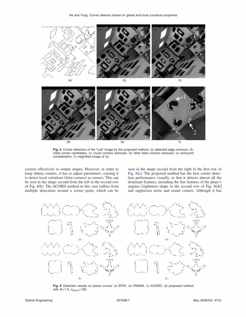
.1 Results at Different Stageso illustrate how the proposed method works, an imageith a large number of acute, obtuse, and round corners issed for the test. Figure 5 depicts the processed images atarious stages. Figure 5�a� depicts the Canny edge map.igure 5�b� depicts the initial corner candidates. After ap-lying round-corner removal based on an adaptive thresh-ld, corner candidates with curvature similar to their neigh-orhood are eliminated, and the result is shown in Fig. 5�c�.he round corners in the arcs at the right-hand center of the
mage have all been eliminated, such as corner candidate 1.
Fig. 4 Feature of different sizes: �a� extendedcorners with similar local properties but differen
ptical Engineering 057008-
However, at the top image boundary, many false cornersare still present. By checking the angle of corner candi-dates, these false corners �due to noise and local variations�can also be eliminated, and the result is shown in Fig. 5�d�.By treating end points of open contours as true corners, weobtain the final detection result as shown in Fig. 5�e�. InFig. 5�f�, corner candidate 1 is an example of a round cor-ner; it appeared only in the initial corner stage, and waseliminated at the round-corner removal stage. Another ex-ample is corner candidate 2: As a trivial feature in themiddle of a long straight line, it was eliminated at the false-corner removal stage through angle checking, and it wasrecovered at the end-point stage as a corner at a T junction.This is why it is included in Fig. 5�c� and 5�e�, but not inFig. 5�d�.
3.2 Test Results on Planar CurvesTo evaluate the performance of the proposed method onplanar curves, we have chosen some published test shapesof different sizes and features from Chetverikov andSzabo10 and selected the two best-performing detectors,BT87 and IPAN99, from their comparative work on thefollowing corner detectors: RJ73,11 RW75,12 FD77,13
BT87,14 and IPAN99.10 We then compared them withACORD25 and our proposed method; the test results areshown in Fig. 6. It should be noted that in Fig. 6�a�–6�c�,parameter values are tuned to get the best result of eachshape. On the other hand, in Fig. 6�d�, the same parametervalues are used for the proposed method to process thewhole set of input shapes. Among all these detectors, BT87tends to miss some of the obvious true corners, as can beseen in the rightmost shape in the second row of Fig. 6�a�,and is not able to suppress some of the round corners, asdepicted in shape second from the right in the first row ofFig. 6�a�. On the other hand, IPAN99 can suppress round
n of round corner; �b� curvature plot of �a�; �c�l properties.
versiot globa
May 2008/Vol. 47�5�6
cktbom
He and Yung: Corner detector based on global and local curvature properties
O
orners effectively in simple shapes. However, in order toeep obtuse corners, it has to adjust parameters, causing ito detect local variations �false corners� as corners. This cane seen in the shape second from the left in the second rowf Fig. 6�b�. The ACORD method in this case suffers fromultiple detections around a corner point, which can be
Fig. 5 Corner detection of the “Lab” image by tinitial corner candidates, �c� round corners remconsideration, �f� magnified image of �b�.
Fig. 6 Detection results on planar curves: �a�with R=1.5, � =162.
obtuseptical Engineering 057008-
seen in the shape second from the right in the first row ofFig. 6�c�. The proposed method has the best corner detec-tion performance visually, in that it detects almost all thedominant features, including the fine features of the plane’sengines �rightmost shape in the second row of Fig. 6�d��and suppresses noise and round corners. Although it has
posed method: �a� detected edge contours, �b��d� other false corners removed, �e� end-point
�b� IPAN99, �c� ACORD, �d� proposed method
he prooved,
BT87,
May 2008/Vol. 47�5�7
doapu
3IcT
He and Yung: Corner detector based on global and local curvature properties
O
etected a false corner in the leftmost shape in the first rowf Fig. 6�d�, this incorrect detection can be removed bydjusting R and �obtuse appropriately. In summary, the pro-osed detector works quite well on different-size featuressing the same R and �obtuse.
.3 Test Results on Gray-Level Imagesn this subsection we have chosen Mokhtarian et al.27,28,33
omparison as our evaluation basis and extended it further.o perform an objective evaluation, a reference solution for
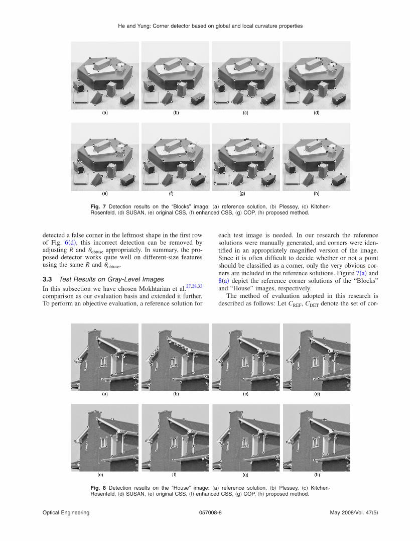
Fig. 7 Detection results on the “Blocks” imaRosenfeld, �d� SUSAN, �e� original CSS, �f� enh
Fig. 8 Detection results on the “House” imagRosenfeld, �d� SUSAN, �e� original CSS, �f� enh
ptical Engineering 057008-
each test image is needed. In our research the referencesolutions were manually generated, and corners were iden-tified in an appropriately magnified version of the image.Since it is often difficult to decide whether or not a pointshould be classified as a corner, only the very obvious cor-ners are included in the reference solutions. Figure 7�a� and8�a� depict the reference corner solutions of the “Blocks”and “House” images, respectively.
The method of evaluation adopted in this research isdescribed as follows: Let CREF, CDET denote the set of cor-
reference solution, �b� Plessey, �c� Kitchen-CSS, �g� COP, �h� proposed method.
reference solution, �b� Plessey, �c� Kitchen-CSS, �g� COP, �h� proposed method.
ge: �a�anced
e: �a�anced
May 2008/Vol. 47�5�8

nfdlbttcdliirTd
pdCm1en
D
P
K
S
O
E
C
P
D
P
K
S
O
E
C
P
He and Yung: Corner detector based on global and local curvature properties
O
ers from the reference solution and the set of cornersound by a particular detector, respectively. Let di,j be theistance difference between the i’th corner in the referenceist �Ci� and the j’th corner �Cj� in the detected list. If di,j
etween Ci and Cj is minimum for ∀i , j, and if di,j �Dmax,hen Cj is labeled as a correct detection of Ci, and is alsoermed a true corner; otherwise, Ci is labeled as a missedorner. Here Dmax is defined to be the maximum admissibleistance difference between Ci and Cj. In other words, theocalization error can be up to Dmax, which is set to 4 pixelsn the following evaluation. The corners labeled as missedn CREF are considered as true corners not detected, and theemaining corners in CDET are considered as false corners.he localization error is calculated as the mean of all theistances di,j for those correctly detected corners.
Using this evaluation method, the detection results of theroposed method are compared with those six other corneretectors �Plessey,6 Kitchen-Rosenfeld,4 SUSAN,7 originalSS,27 enhanced CSS,28 and COP8�. The results are sum-arized in Tables 1 and 2 and in Figs. 7 and 8. From Table
, the number of true corners is 59 in the “Blocks” refer-nce solution. The proposed method detected 55 true cor-ers �representing 93%�, while it has the least number of
Table 1 Evaluation results for the “Blocks” image.
etectorTrue
cornersMissedcorners
Falsecorners
Localizationerror
lessey 39 20 19 1.6045
itchen-Rosenfeld 48 11 14 1.5180
USAN 44 15 19 1.5453
riginal CSS 55 4 15 1.8502
nhanced CSS 54 5 9 0.9755
OP 51 8 26 1.6918
roposed 55 4 2 1.4010
Table 2 Evaluation results for the “House” image.
etectorTrue
cornersMissedcorners
Falsecorners
Localizationerror
lessey 53 28 50 1.5773
itchen-Rosenfeld 59 22 36 1.6561
USAN 60 21 29 1.8428
riginal CSS 63 18 18 1.5285
nhanced CSS 49 32 12 1.3251
OP 52 29 18 1.8980
roposed 66 15 5 0.9901
ptical Engineering 057008-
false corners �only 2�, although the localization error isonly the second best, behind the enhanced CSS method.The two CSS methods performed quite well too, with theoriginal CSS performing ever so slightly better than theenhanced CSS on true corners, but with a lot more falsecorners �15 versus 9�. On the other hand, the original CSShas almost twice as much localization error as the enhancedCSS, which has the largest error in this group of detectors.The other corner detectors performed substantially poorerin that their percentage of success for true corners rangesfrom 68% to 86%, with many more false corners detected.Similar results are shown in Table 2. Due to the complexityof the “House” image, all the corner detectors had a lowersuccess rate in detecting true corners �the best is 82% forthe proposed method, followed by the original CSS at78%�. The false-corner detection rate has also gone up forall the detectors, except for COP. The fact remains that theproposed method has only 5 false corners, while the nextbest is the enhanced CSS with 12 false corners. The local-ization error of the proposed method is just under 1 pixelon average, while the rest are substantially higher. In sum-mary, the proposed method remains the most successful indetecting true corners, with the least number of false cor-ners and amount of localization error. Both sets of resultshighlight the importance of considering the local and globalcurvature properties of corners and achieving a balance be-tween the two in detection.
3.4 Objective Measure Based on FeatureCorrespondence
The results in Secs. 3.2 and 3.3 are subjective in that theyillustrate the similarity between a detector’s and a human’sview of what a corner is. In this section, we consider amore objective measure by applying the proposed algo-rithm to a feature correspondence system and comparingthe feature matching rate with those of SUSAN,7 GFtT,34
and SIFT.35
As depicted in Fig. 9, with two different frames in a realtraffic scene as input, our testing system extracts corners ofa target vehicle in the near frame, and then finds their cor-respondence in the far frame. Correspondences are soughtby hierarchical block-based matching algorithms�HBMAs�, scaling the target vehicle in the far frame to thesame size as the one in the near frame, and inversely scal-ing after matching to fit its original position in the farframe. It should be noted that since the SIFT algorithmincludes feature matching as well as feature extraction, thepreceding feature correspondence procedure is not neces-sary for it. The difficulty of the correspondence problem isthat shadows or reflections on vehicle surfaces couldchange the vehicle’s appearance significantly, especially inregions of highly reflective material, such as the wind-screen and windows of a vehicle. These features may bedetected and classified as features of a vehicle, since sub-stantial edges or junctions may appear in the captured im-age even in homogeneous region. However, since lightsources may be continually changing and vehicles are alsomoving, a vehicle’s appearance may be quite different be-tween two consecutive images. Those features due to shad-ows or reflections are not stable enough to provide accuratematching.
May 2008/Vol. 47�5�9

emmdaeSrhnasdit=
He and Yung: Corner detector based on global and local curvature properties
O
In this experiment, the correspondence results of differ-nt detectors are checked manually and labeled as match orismatch; obvious localization errors are also labeled asismatch. Then the matching rate is calculated, which is
efined as the ratio of matched features to detected features,nd is used to evaluate the performance of the four featurextraction algorithms in this system. Parameters of theUSAN and GFtT were tuned to include features that rep-esent the main structure of vehicle and exclude features inomogeneous regions, which tend to mismatch. The bright-ess threshold of SUSAN was set as 45; the quality levelnd minimum distance of GFtT were set as 0.2 and 5 re-pectively. The SIFT function has many parameters; theefault values were chosen to emulate Lowe’s originalmplementation. The parameters of the proposed corner de-ector were set as the defaults, that is, R=1.5 and �obtuse162 deg. Usually, the proposed corner detector is applied
Fig. 9 Diagram of feat
12 34 5
67
8 91011 12 131415 16
1718 1920
2122 23
24 25 2627 2829 30 313233343536 37 3839
40 414243 44 4546 4748
49
50 51 5253 5455 56 5758 5960
61 6263 646566 67
6869
7071 72 7374 75 76 777879 80 8182 8384 85 8687 88
899091 929394 9596 97 9899100101
1
2 34 56
78
9
10
1112 1314
1516
17
1819
2021
22 2324 25 26
27
282930
3132333435 36
37 38
3940
41
42
43
44 45
46
474849
50
51
52
53 54
55
56 57
58
5960
61
6263 64
65
666768
69
70
7172
774 75 767778
7980 8182 83
84
85 86
8788
899091
929394 95
9697
9899100
101
(a)
1
2
34
56
7
8 910
111213
14 15 161718 192021
222324 25
1
2
3 4
56
7
8 9
10 11121314
15
1617
18
19
2021222324 25
(c)
Fig. 10 Feature corresponding results: �a� SUSmentation boundaries.
ptical Engineering 057008-1
to the Canny edge map. In this experiment, it was alsoapplied to the boundaries of a segmentation result36 to en-hance the matching performance.
The experiment was performed on 16 vehicles in differ-ent traffic scenes. Typical feature correspondence examplesare presented in Fig. 10, and correspondence results aresummarized in Table 3.
SUSAN detected the most features in this experiment.But some of these features lie on the straight part of aboundary �e.g., points 12, 13, 66 in Fig. 10�a��, and someothers lie on the vehicle windows or windscreen �e.g.,points 10, 19 in Fig. 10�a��; these represent most of themismatched features due to SUSAN. GFtT exhibited verypromising performance in this experiment: As shown inFig. 10�b�, only a few features have localization error �e.g.,points 30 and 32 in Fig. 10�b��. SIFT seems unsuitable forthis kind of data, for it detected the least features, and
rrespondence system.
1 2 34
5 67
89 1011 12131415 16 1718
19 20212223
2425262728 29303132
33
34353637383940 41424344 4546 47484950 51
1 2 34
56
78
9 101112131415 16 17 18
19 2021222324
2526
27
28
29303132
33
34353637 383940
4142
4344 45464748
495051
(b)
123 45
678
9 101112
1314 1516
17
19 20 2122 23
24
25 26
27 28
293031
323334 35 3637
38
123 45 6
7 89
10
11
1213
14 151617
18
19
20 2122
23
24
25
2627 28
29 3031
3233
3435
36
37
38
(d)
� GFtT, �c� SIFT, �d� proposed method on seg-
ure co
3
18
AN, �b
May 2008/Vol. 47�5�0

mpinaedstavwrsa
tp�be
3TT
l
tmsdctTswtceoaTt
He and Yung: Corner detector based on global and local curvature properties
O
issed some significant corners of the vehicle, as well asroducing some erratic mismatches, �e.g., points 16, 17, 19n Fig. 10�c��. The proposed corner detector could suppressoise and trivial details on planar curves, and thereforechieved reasonable correspondence performance. How-ver, when it was applied to the Canny edge map, it alsoetected some unstable features in windows or wind-creens, which led to some mismatches. When we appliedhe proposed corner detector to the segmentation boundary,s depicted in Fig. 10�d�, it detected all the key corners of aehicle without any ambiguous features. Of course, theell-segmented input contributes a lot to this excellent cor-
espondence result. We believe utilizing a sophisticatedegmentation algorithm to suppress trivial information isdvantageous to curve-based corner detectors.
To sum up, in terms of matching rate, the proposed de-ector on the segmentation boundary �98.14%� has the besterformance, and the proposed detector using Canny92.28%� is worse than GFtT �94.87%�. They all performetter than SUSAN �87.29%� and SIFT �83.75%� in thisvaluation.
.5 Processing Speedhe proposed detector has been implemented in Matlab.he source code can be obtained from
http://www.mathworks.com/matlabcentral/fileexchange/oadFile.do?objectId�7652&objectType�File
The proposed detection algorithm was executed 100imes on a 1.8-GHz PC with 256 Mbyte of memory, and
ean execution times were measured. The processingpeed of the subcomponents of the proposed algorithm isepicted in Table 4. The processing time for the planarurves shown in Fig. 6, excluding edge detection and con-our extraction, varied from 0.015 to 0.046 s. According toable 4, the “Block” image and “House” image requiredimilar time, while the “Lab” image required more time,hich is reasonable in view of their difference in sizes. In
he three subcomponents of the algorithm, corner detectiononsumes much less time than edge detection and contourxtraction, since the proposed corner detection algorithm isnly performed on one scale instead of parsing featurescross the entire scale space like multiscale algorithms.his enables the proposed method to be deployed in real-
ime applications.
Table 3 Evaluation
DetectorDetectedfeatures
SUSAN 2408
GFtT 1227
SIFT 603
Proposed: 1178
On Canny
On segmentation boundary 913
ptical Engineering 057008-1
4 ConclusionsThe main contribution of this paper is the consideration ofboth global and local curvature of corners in the detection,in which the use of adaptive threshold and dynamic ROS toidentify corners helps to take both properties into account.As a result, different parameters can be automatically de-termined for different images, different curves, and differ-ent kinds of corner candidates.
To summarize, the advantages of the proposed methodare that it: �1� increases the number of true corners detectedand reduces the number of false corners detected for theimages tested; �2� produces relatively low localization er-rors; �3� supports two controllable parameters �R and�obtuse� to achieve consistent detection performance fromimage to image; and �4� identifies corners not only accord-ing to their local curvature but also according to their glo-bal curvature, detects dominant feature of different sizes,and ignores trivial details. The proposed corner detectorcould potentially be utilized in many applications, e.g., mo-tion estimation, object tracking, stereo matching, cameracalibration, and 3-D reconstruction. So far, its implementa-tions realized by the author include a camera calibrationsystem using road lane markings,37,38 a visual vehicle speedestimation system.39 and a vehicle 3-D wire-frame recon-struction system.40
AcknowledgmentsWe would like to express our thanks to Farzin Mokhtarianand Dmitry Chetverikov for making their work available tous for comparison.
responding results.
Matchedfeatures
Mismatchedfeatures
Matchingrate �%�
2102 306 87.29
1164 63 94.87
505 98 83.75
1087 91 92.28
896 16 98.14
Table 4 Time requirements.
Time �s�
Task Blocks�256�256�
House�256�256�
Lab�512�512�
Edge detection 0.681 0.658 2.616
Contour extraction 0.580 0.564 2.960
Corner detection 0.088 0.114 0.358
on cor
May 2008/Vol. 47�5�1

R
1
1
1
1
1
1
1
1
1
1
2
2
2
2
2
2
2
2
2
2
3
He and Yung: Corner detector based on global and local curvature properties
O
eferences
1. G. S. K. Fung, N. H. C. Yung, and G. K. H. Pang, “Vehicle shapeapproximation from motion for visual traffic surveillance,” in Proc.IEEE 4th Int. Conf. on Intelligent Transportation Systems, pp. 201–206 �2001�.
2. G. S. Manku, P. Jain, A. Aggarwal, A. Kumar, and L. Banerjee,“Object tracking using affine structure for point correspondence,” inProc. 1997 IEEE Comput. Soc. Conf. on Computer Vision and Pat-tern Recognition, pp. 704–709 �1997�.
3. B. Serra and M. Berthod, “3-D model localization using high-resolution reconstruction of monocular image sequences,” IEEETrans. Image Process. 6�1�, 175–188 �1997�.
4. L. Kitchen and A. Rosenfeld, “Gray level corner detection,” PatternRecogn. Lett. 1, 95–102 �1982�.
5. H. P. Moravec, “Towards automatic visual obstacle avoidance,” inProc. Int. Joint Conf. on Artificial Intelligence, p. 584 �1977�.
6. C. Harris and M. Stephens, “A combined corner and edge detector,”in Fourth Alvey Vision Conf., pp. 147–151 �1988�.
7. S. Smith and J. Brady, “SUSAN—a new approach to low-level imageprocessing,” Int. J. Comput. Vis. 23�1�, 45–48 �1997�.
8. S. C. Bae, I. S. Kweon, and C. D. Yoo, “COP: a new corner detector,”Pattern Recogn. Lett. 23�11�, 1349–1360 �2002�.
9. H. C. Liu and M. D. Srinath, “Corner detection from chain-code,”Pattern Recogn. 23, 51–68 �1990�.
0. D. Chetverikov and Z. Szabo, “Detection of high curvature points inplanar curves,” http://visual.ipan.sztaki.hu/corner/index.html �1999�.
1. A. Rosenfeld and E. Johnston, “Angle detection on digital curves,”IEEE Trans. Comput. 22, 875–878 �1973�.
2. A. Rosenfeld and J. S. Weszka, “An improved method of angle de-tection on digital curves,” IEEE Trans. Comput. 24, 940–941 �1975�.
3. H. Freeman and L. S. Davis, “A corner finding algorithm for chain-coded curves,” IEEE Trans. Comput. 26, 297–303 �1977�.
4. H. L. Beus and S. S. H. Tiu, “An improved corner detection algo-rithm based on chain-coded plane curves,” Pattern Recogn. 20, 291–296 �1987�.
5. K. Rangarajan, M. Shah, and D. V. Brackle, “Optimal corner detec-tor,” Comput. Vis. Graph. Image Process. 48, 230–245 �1989�.
6. F. Arrebola, A. Bandera, P. Camacho, and F. Sandoval, “Corner de-tection by local histograms of contour chain code,” Electron. Lett.33�21�, 1769–1771 �1997�.
7. W. C. Chen and P. Rockett, “Bayesian labeling of corners using agrey-level corner image model,” in Proc. IEEE Int. Conf. on ImageProcessing, pp. 687–690 �1997�.
8. F. Chabat, G. Yang, and D. Hansell, “A corner orientation detector,”Image Vis. Comput. 17, 761–769 �1999�.
9. A. Quddus and M. Fahmy, “Fast wavelet-based corner detection tech-nique,” Electron. Lett. 35�4�, 287–288 �1999�.
0. C. Achard, E. Bigorgne, and J. Devars, “A sub-pixel and multispec-tral corner detector,” in Proc. 11th Int. Conf. on Pattern Recognition,pp. 971–974 �2000�.
1. F. Shen and H. Wang, “Real time gray level corner detector,” in Proc.6th Int. Conf. on Control, Automation, Robotics and Vision �2000�.
2. F. Shen and H. Wang, “Corner detection based on modified Houghtransform,” Pattern Recogn. Lett. 23�8�, 1039–1049 �2002�.
3. C. Urdiales, C. Trazegnies, A. Bandera, and F. Sandoval, “Cornerdetection based on an adaptively filtered curvature function,” Elec-tron. Lett. 39, 426–428 �2003�.
4. A. Rattarangsi and R. T. Chin, “Scale-based detection of corners ofplanar curves,” IEEE Trans. Pattern Anal. Mach. Intell. 14�4�, 430–449 �1992�.
5. B. K. Ray and R. Pandyan, “ACORD—an adaptive corner detectorfor planar curves,” Pattern Recogn. 36, 703–708 �2003�.
6. F. Mokhtarian and A. K. Mackworth, “A theory of multi-scalecurvature-based shape representation for planar curves,” IEEE Trans.Pattern Anal. Mach. Intell. 14�8�, 789–805 �1992�.
7. F. Mokhtarian and R. Suomela, “Robust image corner detectionthrough curvature scale space,” IEEE Trans. Pattern Anal. Mach.Intell. 20�12�, 1376–1381 �1998�.
8. F. Mokhtarian and F. Mohanna, “Enhancing the curvature scale spacecorner detector,” Proc. Scandinavian Conf. on Image Analysis, pp.145–152 �2001�.
9. X. C. He and N. H. C. Yung, “Curvature scale space corner detectorwith adaptive threshold and dynamic region of support,” in Proc.17th Int. Conf. on Pattern Recognition, pp. 791–794 �2004�.
0. H. Spath, “Least-squares fitting by circles,” Computing 57, 179–185�1996�.
ptical Engineering 057008-1
31. G. Taubin, “Estimation of planar curves, surfaces and nonplanarspace curves defined by implicit equations, with applications to edgeand range image segmentation,” IEEE Trans. Pattern Anal. Mach.Intell. 13�11�, 1115–1138 �1991�.
32. P. l. Rosin, “Multiscale representation and matching of curves usingcodons,” CVGIP: Graph. Models Image Process. 55, 286–310�1993�.
33. F. Mokhtarian, “Image corner detection through curvature scalespace,” http://www.ee.surrey.ac.uk/Research/VSSP/demos/corners/�2001�.
34. J. B. Shi and C. Tomasi, “Good feature to track,” in Proc. IEEE Conf.on Computer Vision and Pattern Recognition, pp. 593–600 �1994�.
35. D. G. Lowe, “Distinctive image features from scale-invariant key-points,” Int. J. Comput. Vis. 60�2�, 91–110 �2004�.
36. X. C. He, N. H. C. Yung, K. P. Chow, F. Y. L. Chin, R. H. Y. Chung,K. Y. K. Wong, and K. S. H. Tsang, “Watershed segmentation withboundary curvature ratio based merging criterion,” in Proc. NinthIASTED Int. Conf. on Signal and Image Processing, pp. 7–12 �2007�.
37. G. S. K. Fung, N. H. C. Yung, and G. K. H. Pang, “Camera calibra-tion from road lane markings,” Opt. Eng. 42�10�, 2967–2977 �2003�.
38. X. C. He and N. H. C. Yung, “A new method for solving ill-conditionin vanishing point based camera calibration,” Opt. Eng. 46�3�,037202 �2007�.
39. X. C. He and N. H. C. Yung, “A novel algorithm for estimatingvehicle speed from two consecutive images,” in Proc. Eighth IEEEWorkshop on Applications of Computer Vision, p. 12 �2007�.
40. X. C. He, “Feature extraction from two consecutive traffic images for3D wire frame reconstruction of vehicle,” PhD thesis, Univ. of HongKong �2006�.
Xiao Chen He received his BEng andMEng degrees from the University of Sci-ence and Technology of China in 1999 and2002, respectively, and his PhD degreefrom the University of Hong Kong in 2007.He is currently a research associate withthe Department of Computer Science, Uni-versity of Hong Kong. His research interestsinclude pattern recognition, digital imageprocessing, and visual traffic surveillance.
Nelson H. C. Yung received his BSc andPhD degrees from the University ofNewcastle-upon-Tyne, where he was a lec-turer 1985 to 1990. From 1990 to 1993, heworked as senior research scientist in theDepartment of Defence, Australia. He joinedthe University of Hong Kong in late 1993 asassociate professor. He is the founding di-rector of the Laboratory for Intelligent Trans-portation Systems Research at HKU, andalso deputy director of HKU’s Institute of
Transport Studies. Dr. Yung has coauthored five books and bookchapters, and has published more than 100 journal and conferencepapers in the areas of digital image processing, parallel algorithms,visual traffic surveillance autonomous vehicle navigation, and learn-ing algorithms. He serves as reviewer for the IEEE Transactions onSMC, CASVT, Vehicular Technology, and Signal Processing; Opti-cal Engineering; the Journal of Electronic Imaging; HKIE Proceed-ings; Microprocessors and Microsystems; and Robotics and Autono-mous Systems. He was a member of the Advisory Panel of the ITSStrategy Review, Transport Department, HKSAR; regional secretaryof the IEEE Asia-Pacific region; council member of ITS-HK; andchair of the Computer Division of the International Institute for Criti-cal Infrastructures. He is a chartered electrical engineer; member ofthe HKIE and IEE, and senior member of the IEEE. His biographyhas been published in Who’s Who in the World �Marquis, USA�since 1998.
May 2008/Vol. 47�5�2